Sagem Wireless MA520 MA520, OMA520 User Manual DOC MA
Sagem Wireless MA520, OMA520 DOC MA
UserManual.wiki
>
Sagem Wireless
>
MA520 User Manual
>
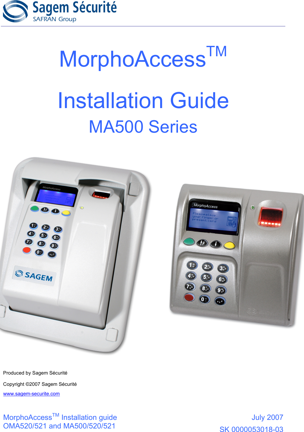
Installation Guide
Contents
1.
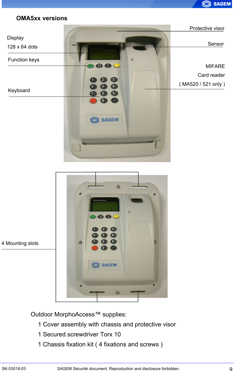
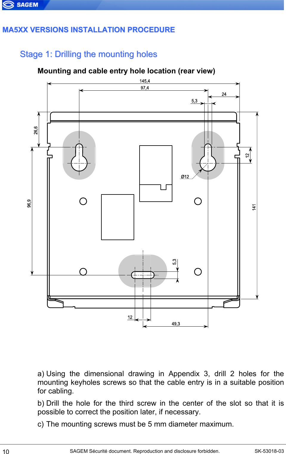
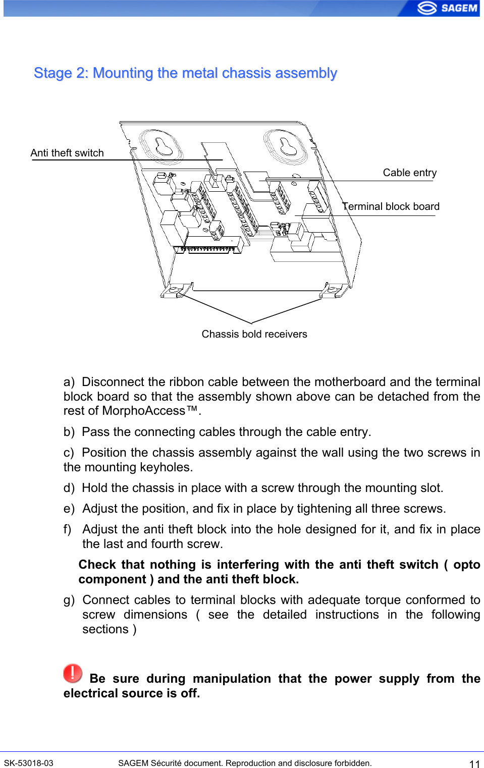
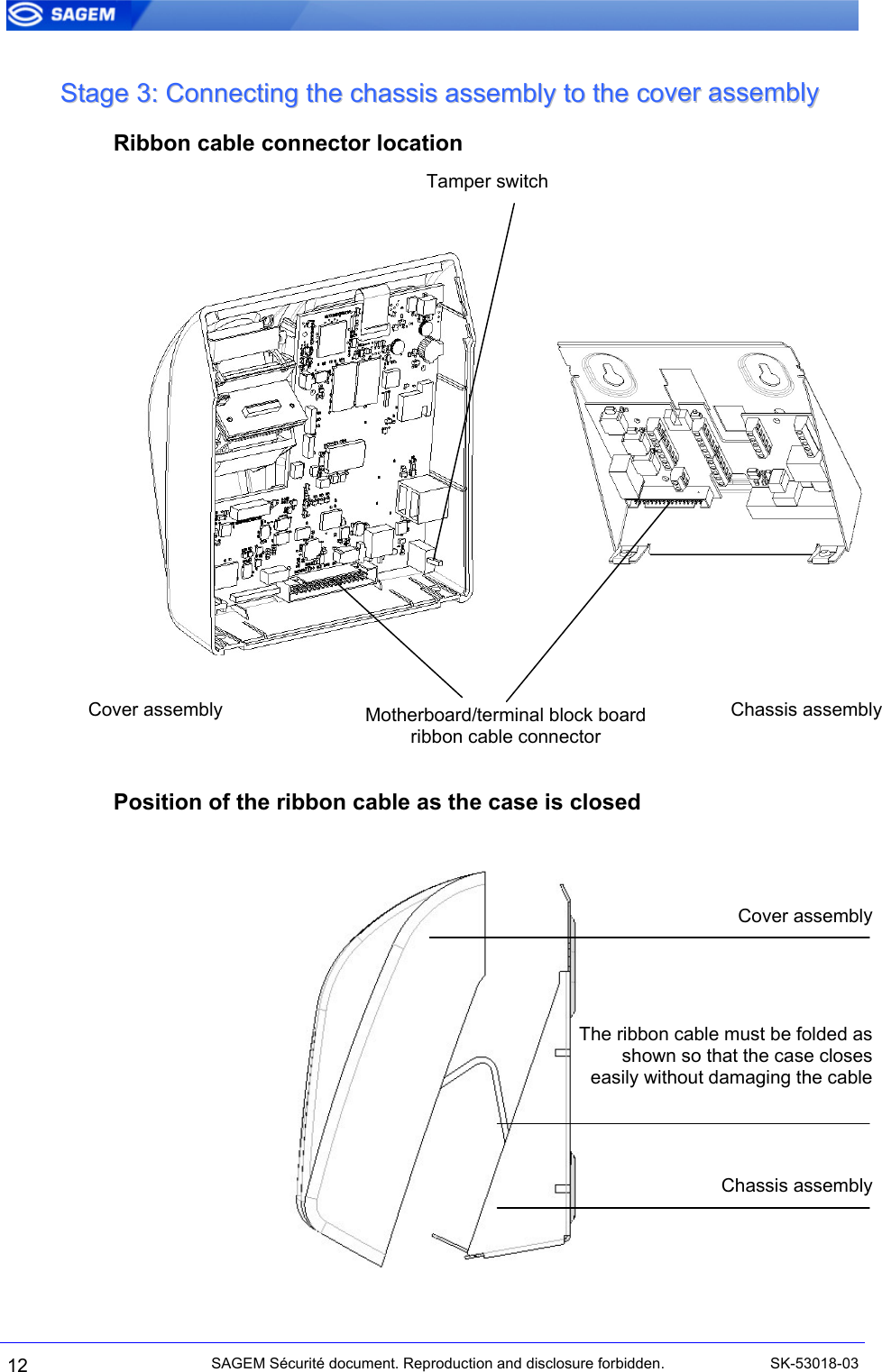
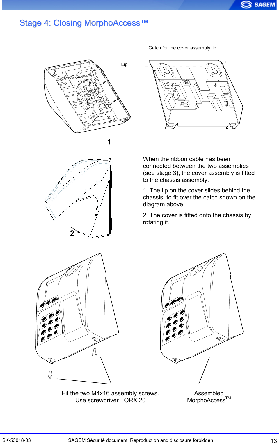
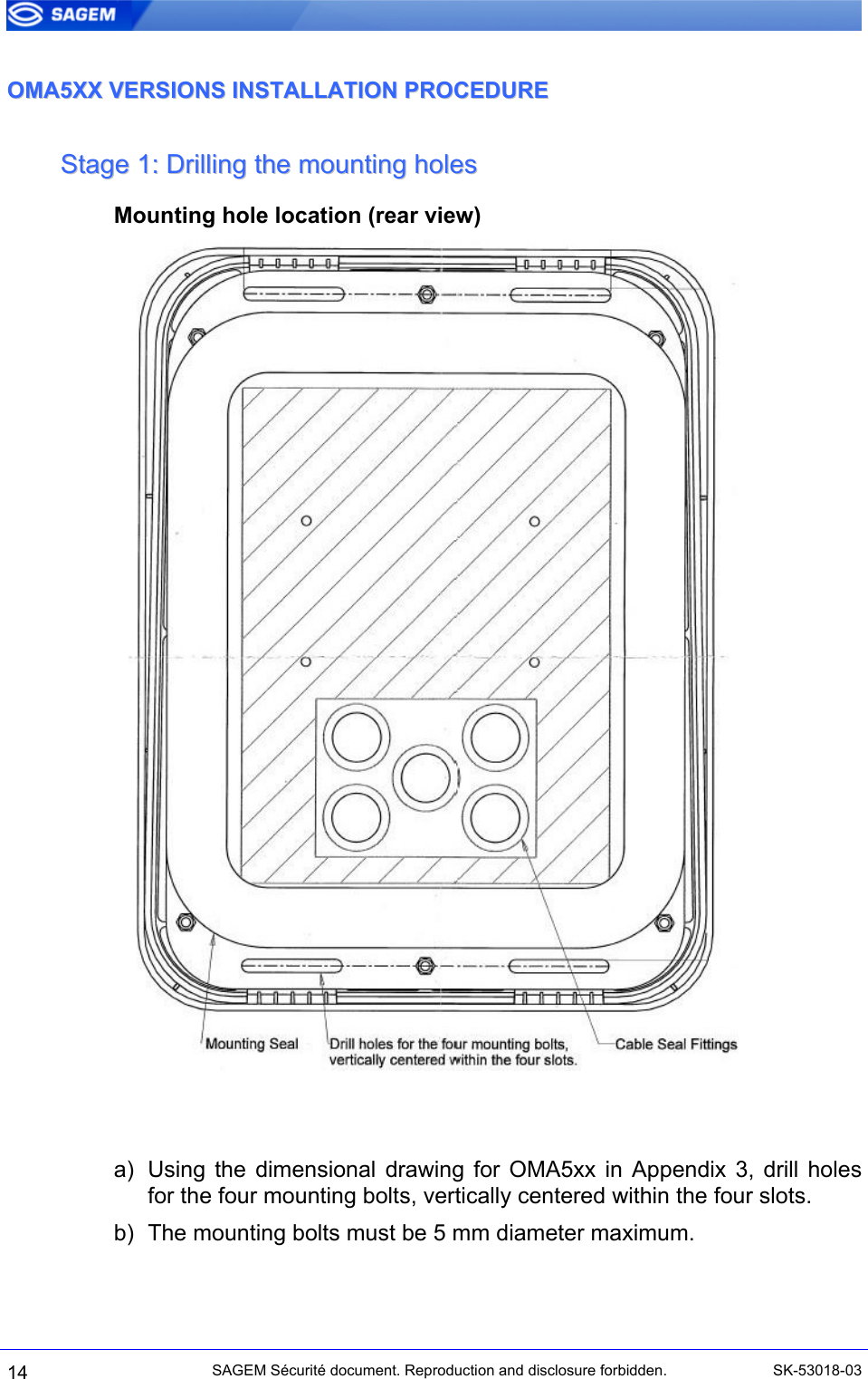
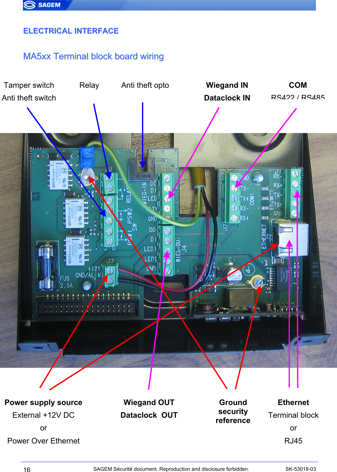
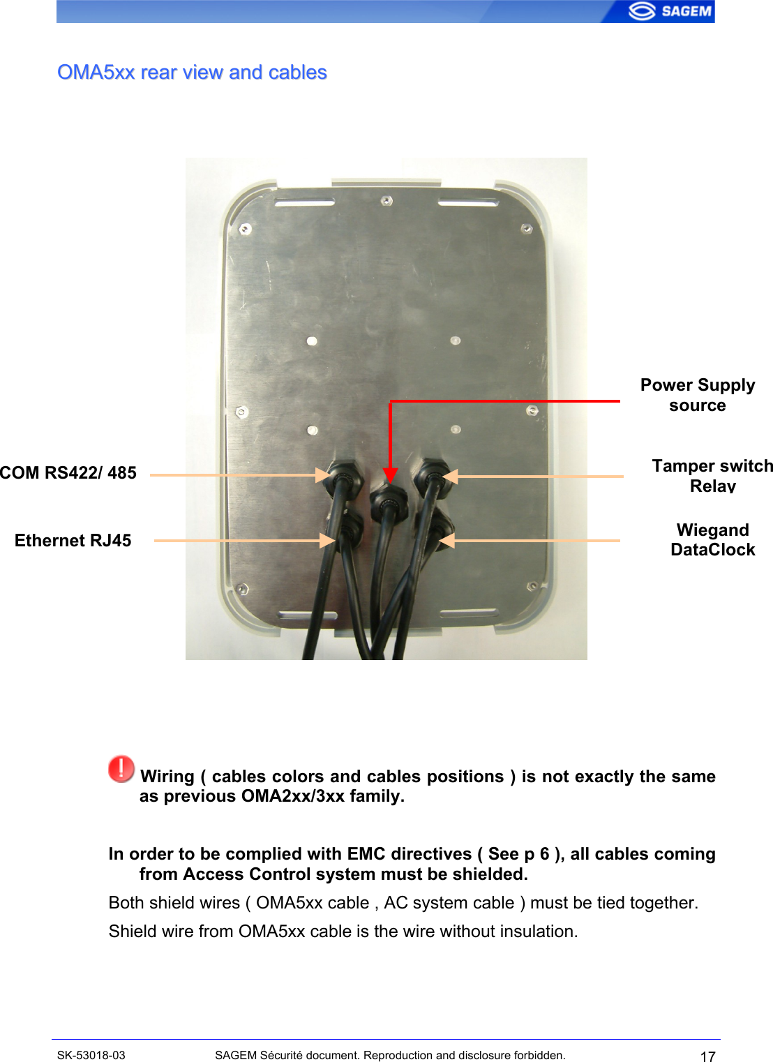
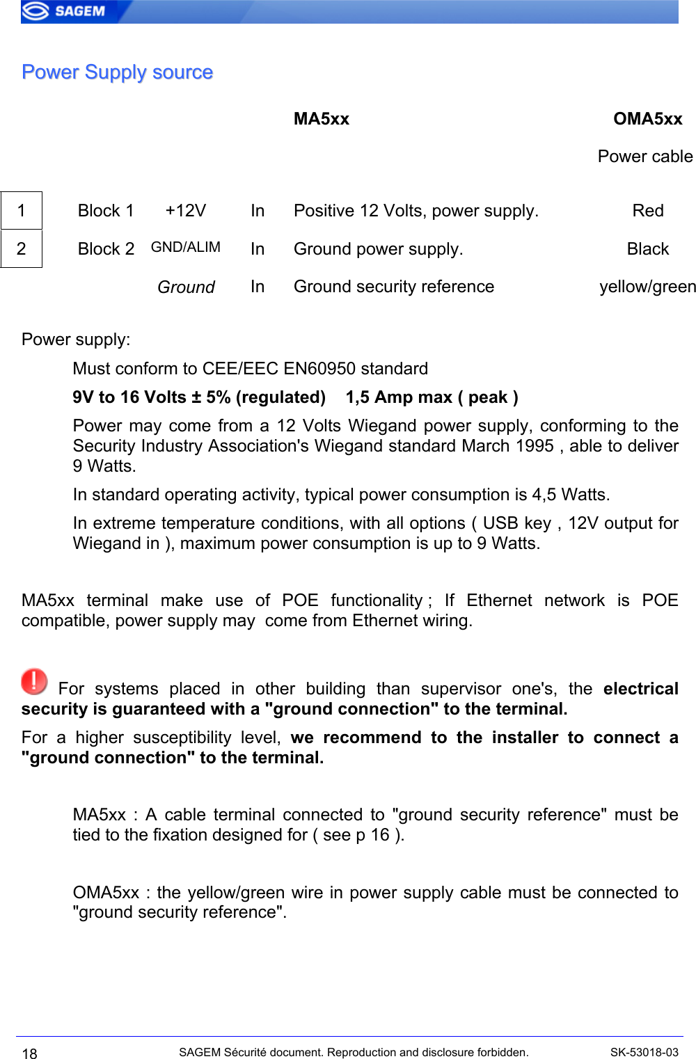
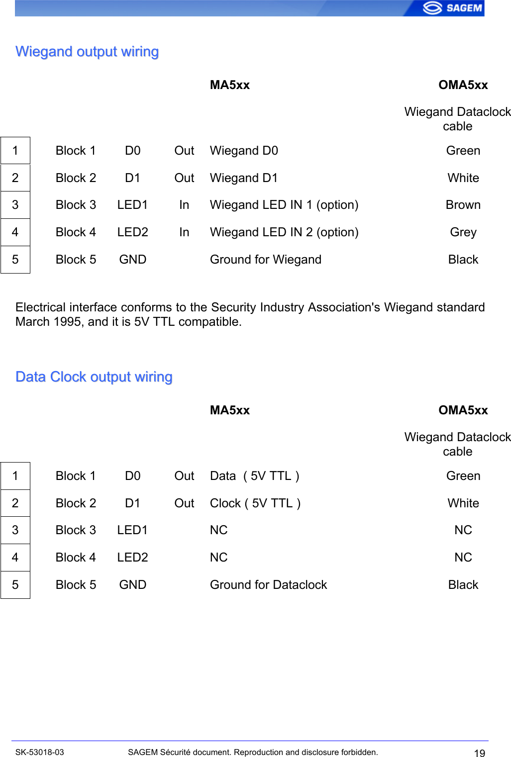
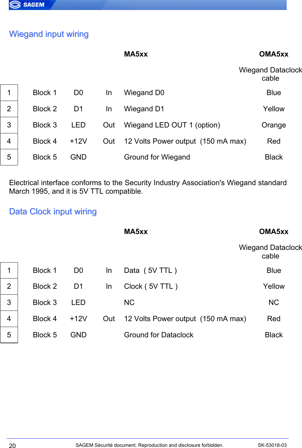
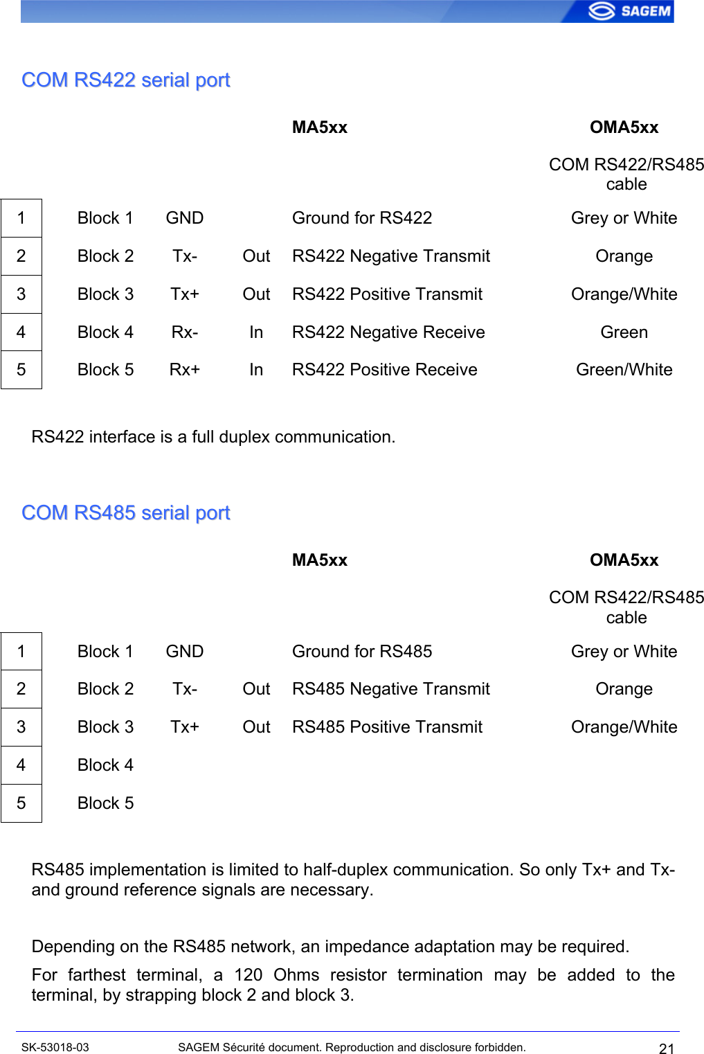
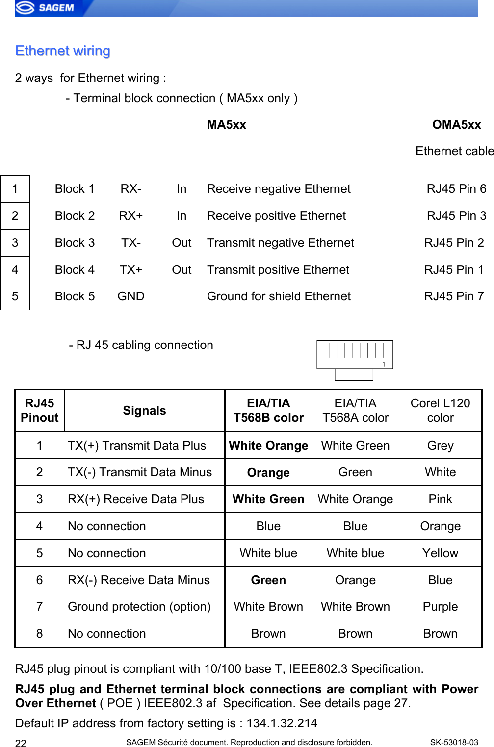
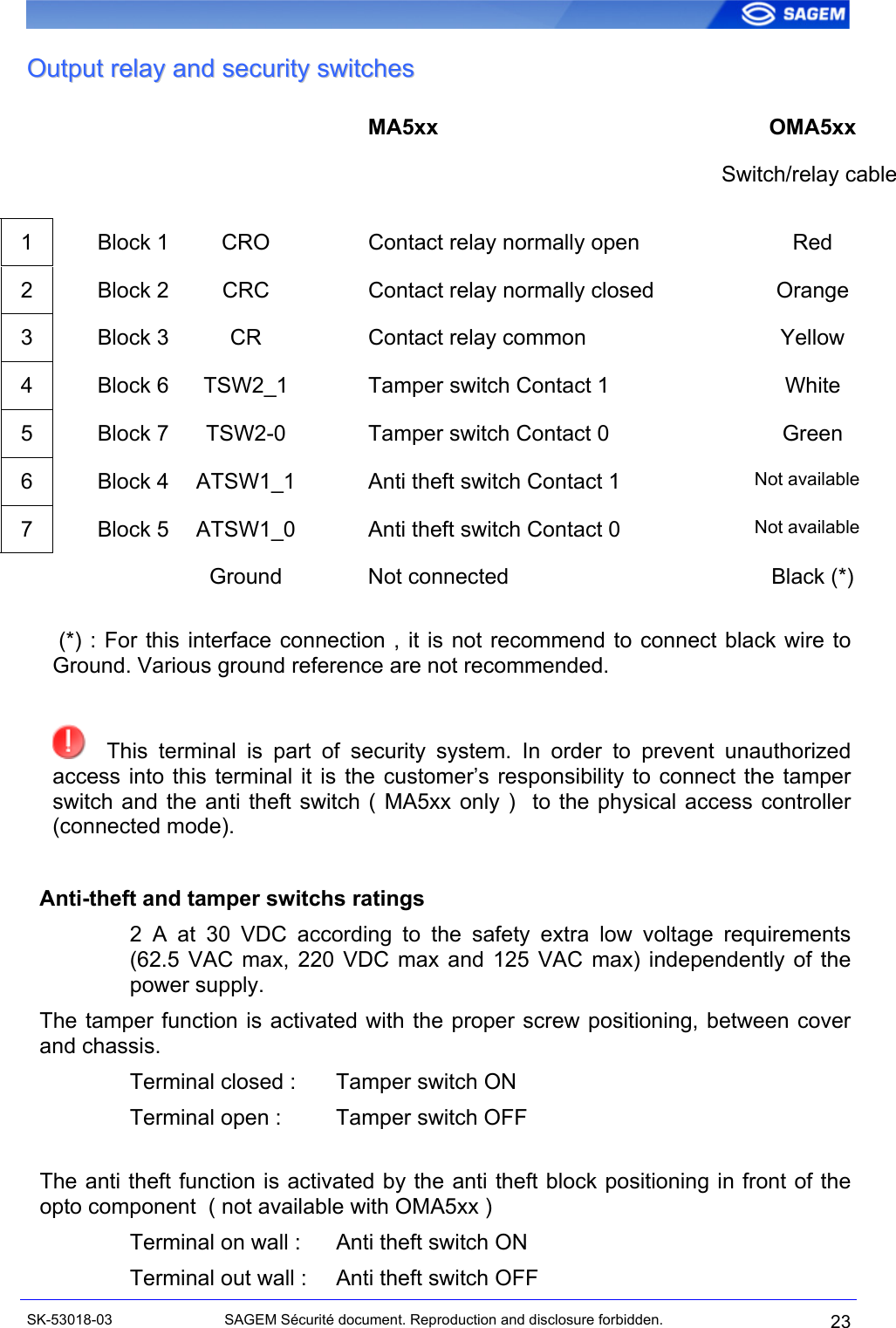
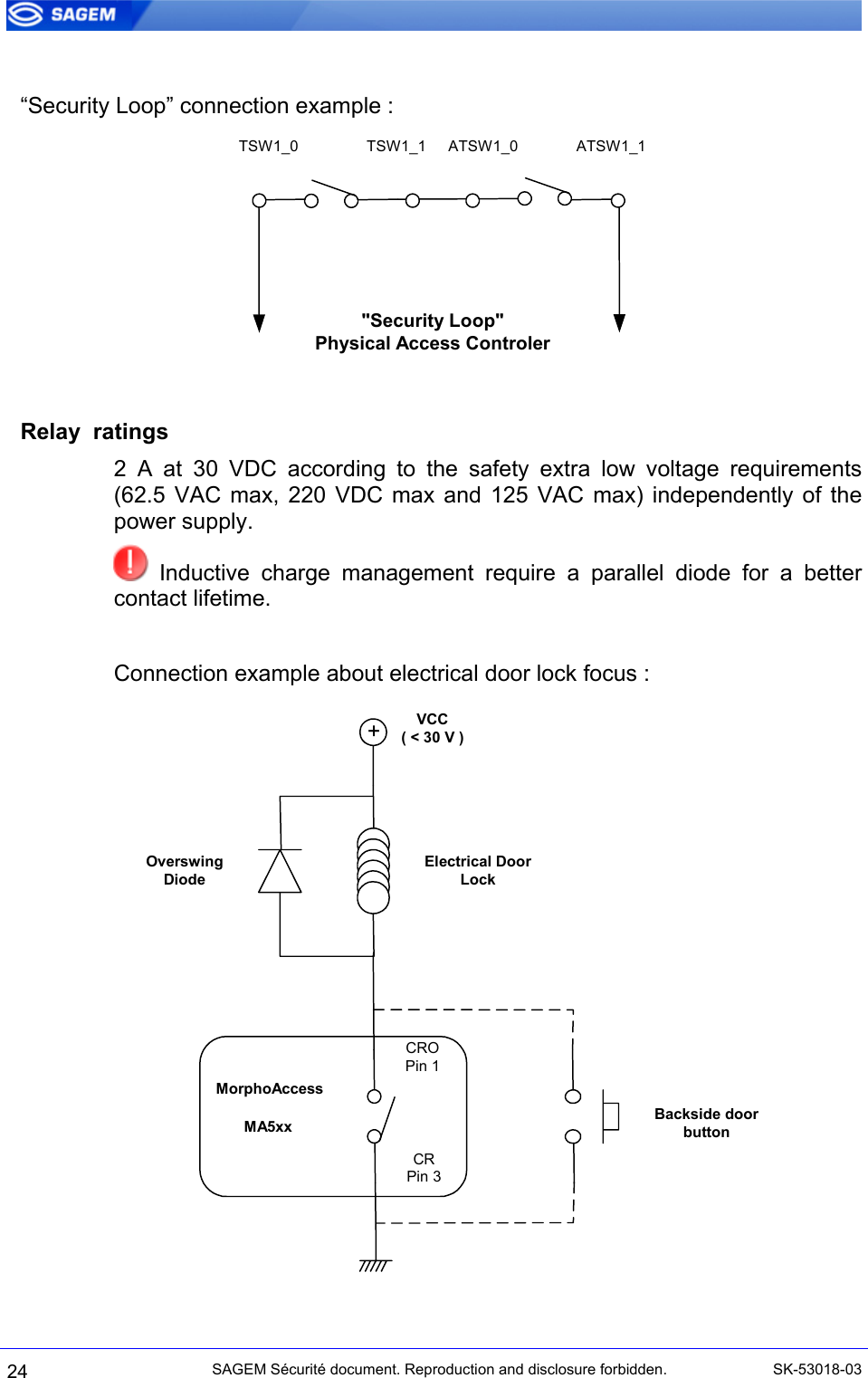
Installation Guide
2.
User Guide
Installation Guide
Navigation menu
Upload a User Manual
Namespaces
Wiki Guide
HTML
PDF
Info
Views
User Manual
Discussion / Help
Navigation