Sercomm SWPIR03N Z-Wave Motion Sensor User Manual Wireless 802 11g Network Camera
Sercomm Corporation Z-Wave Motion Sensor Wireless 802 11g Network Camera
UserManual.wiki
>
Sercomm
>
SWPIR03N User Manual
Users Manual
Navigation menu
Upload a User Manual
Namespaces
Wiki Guide
HTML
PDF
Info
Views
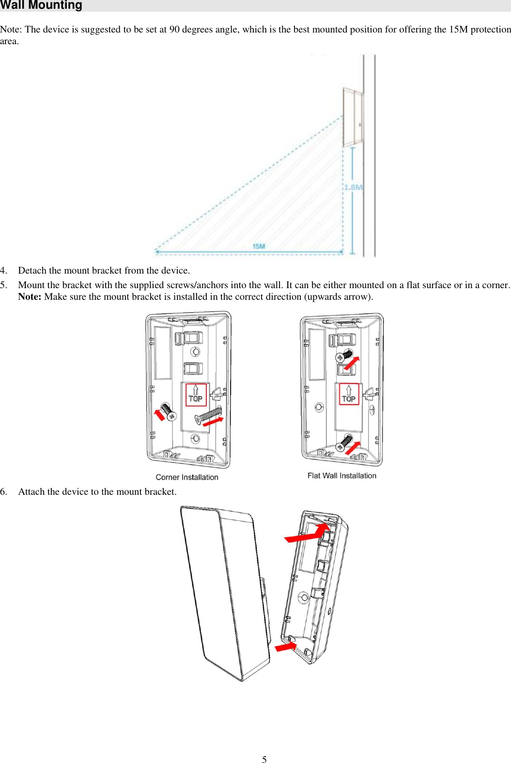
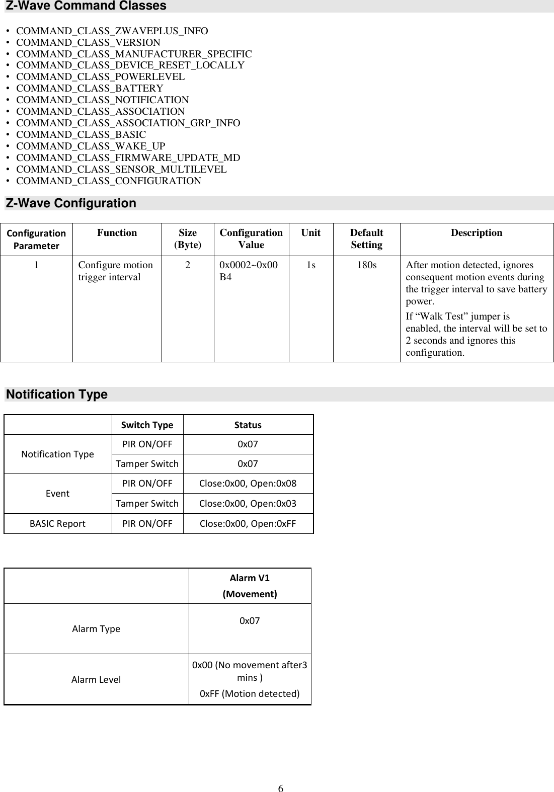
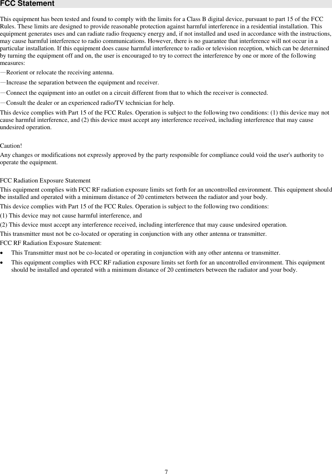
User Manual
Discussion / Help
Navigation