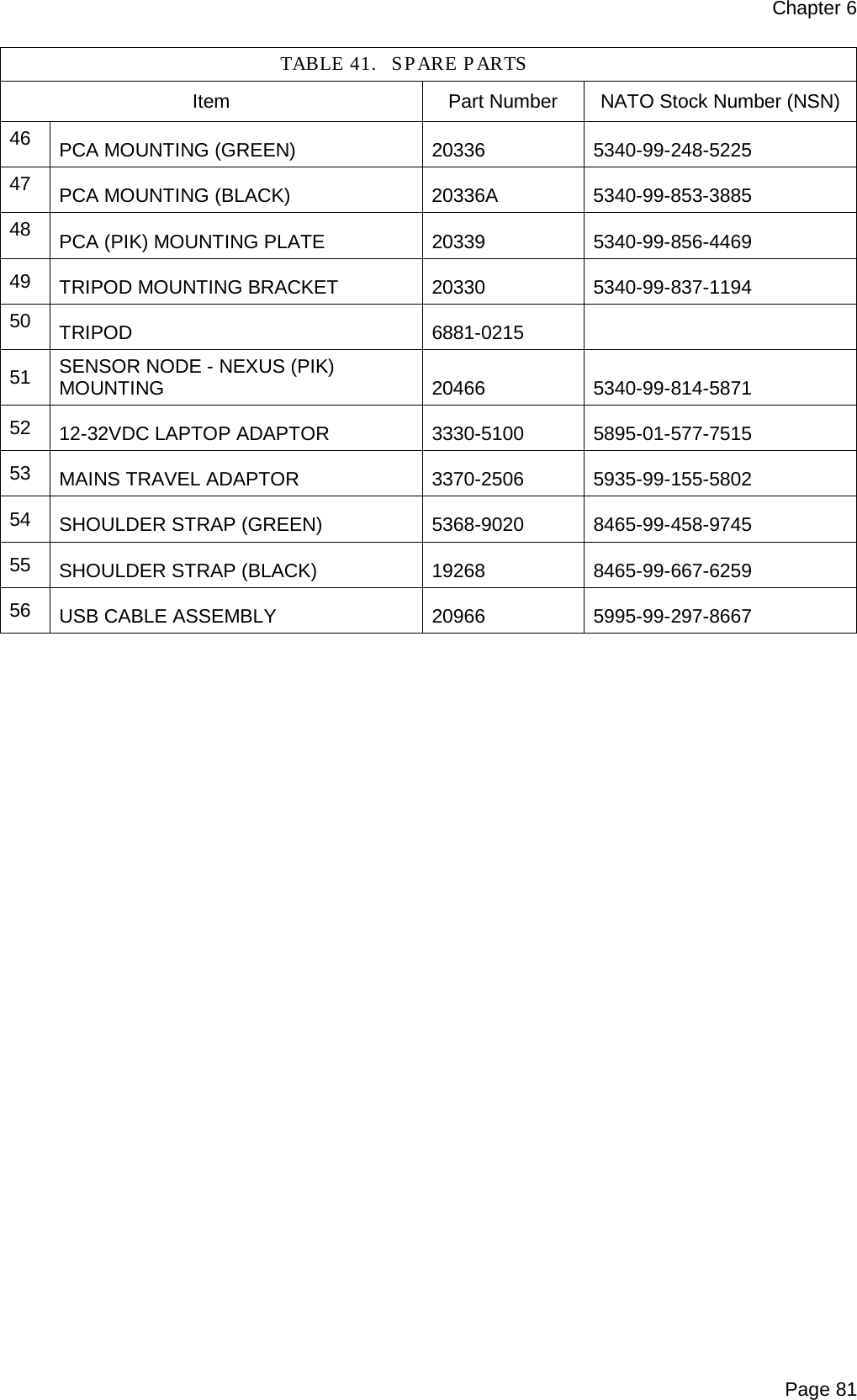
Smiths Detection 2039924 Sensa-LINX, Wireless Early Warning System, 2.4 GHz Variant User Manual Operator s manual
Smiths Detection (Watford) Sensa-LINX, Wireless Early Warning System, 2.4 GHz Variant Operator s manual
Contents
- 1. User Manual
- 2. Quick Reference Guide
User Manual

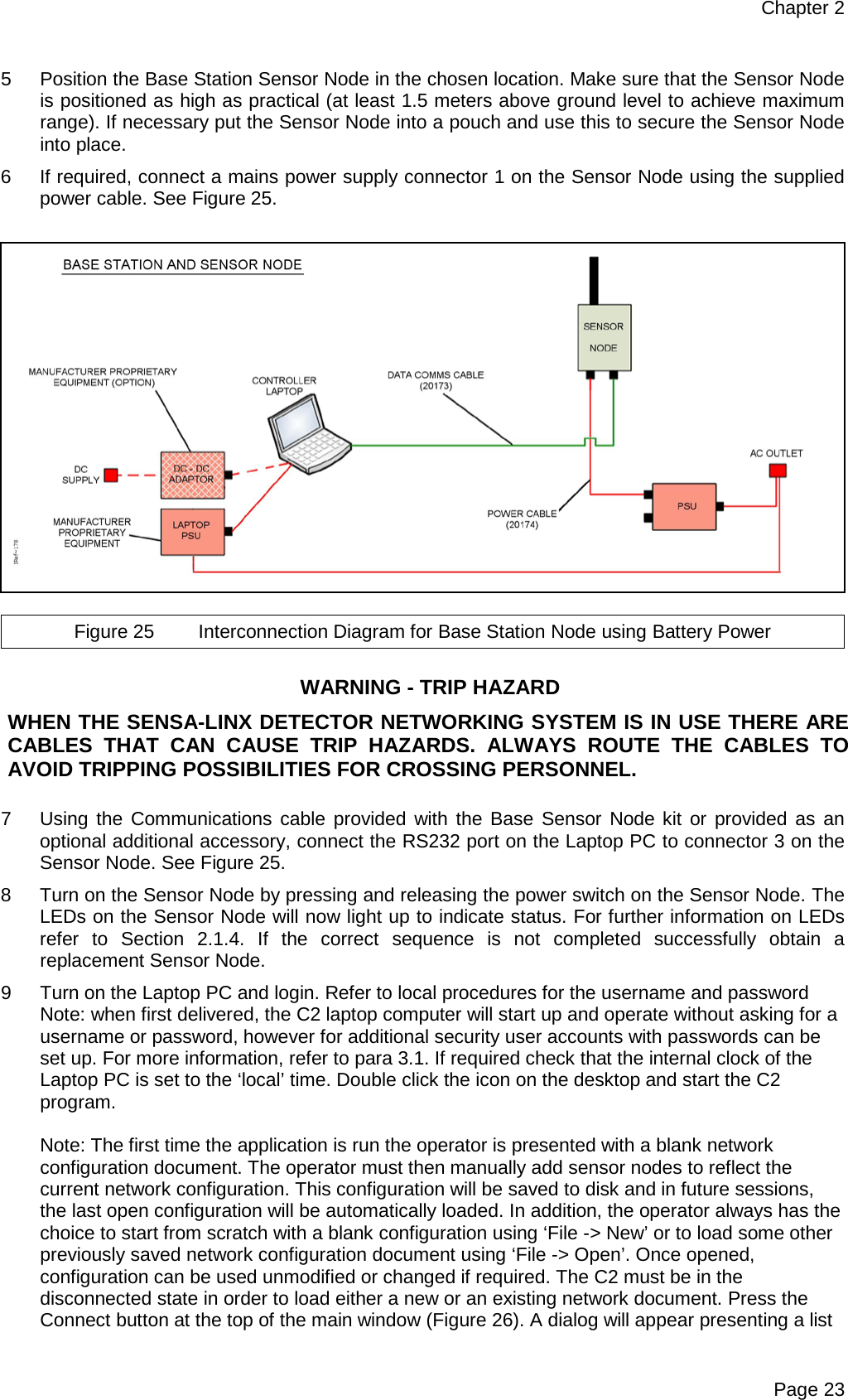
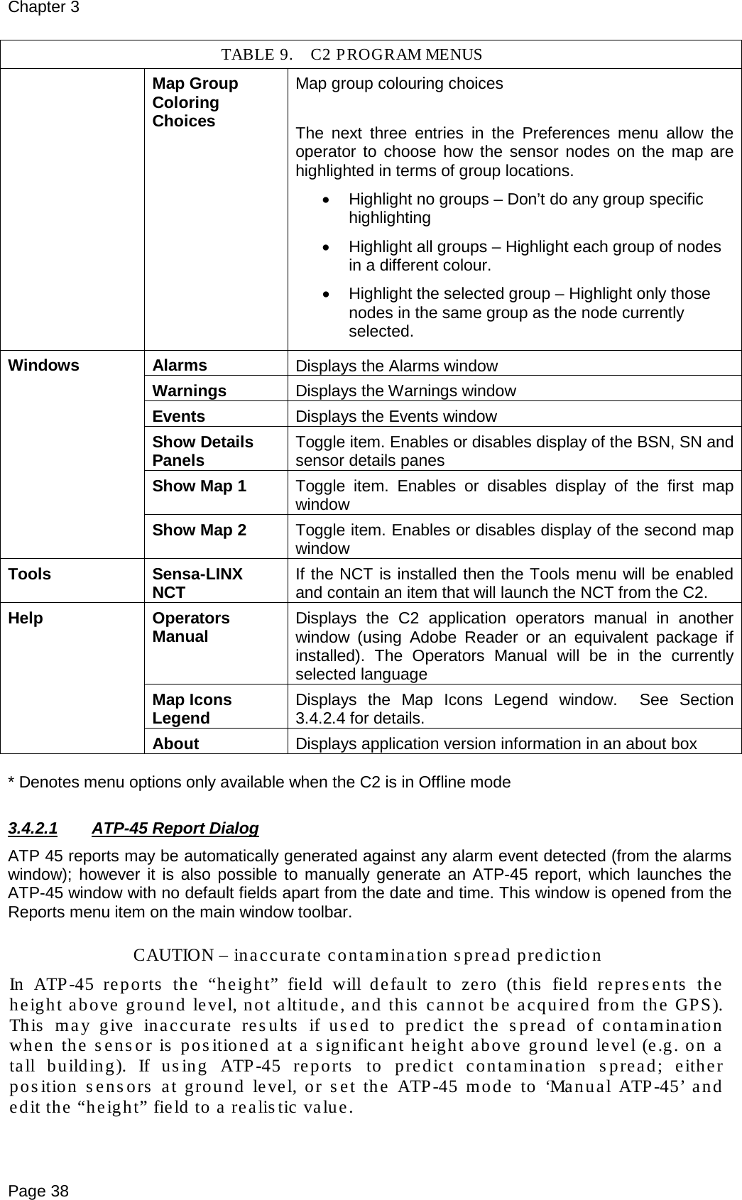
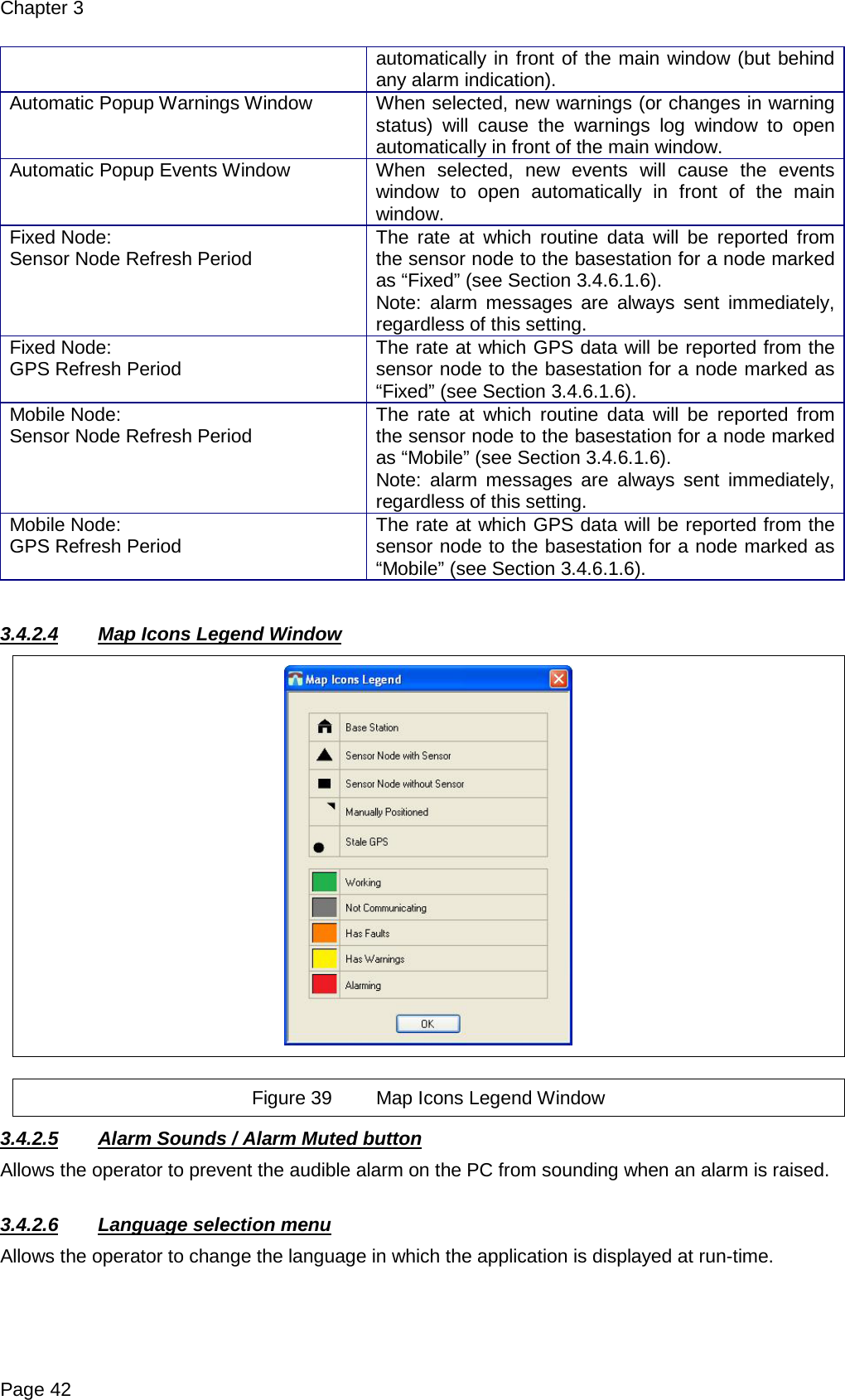
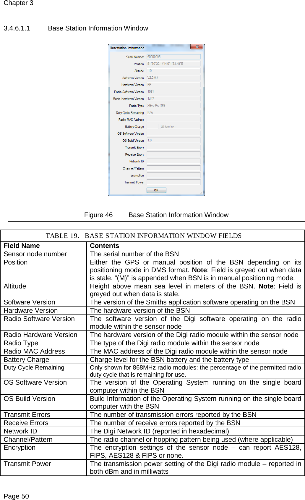
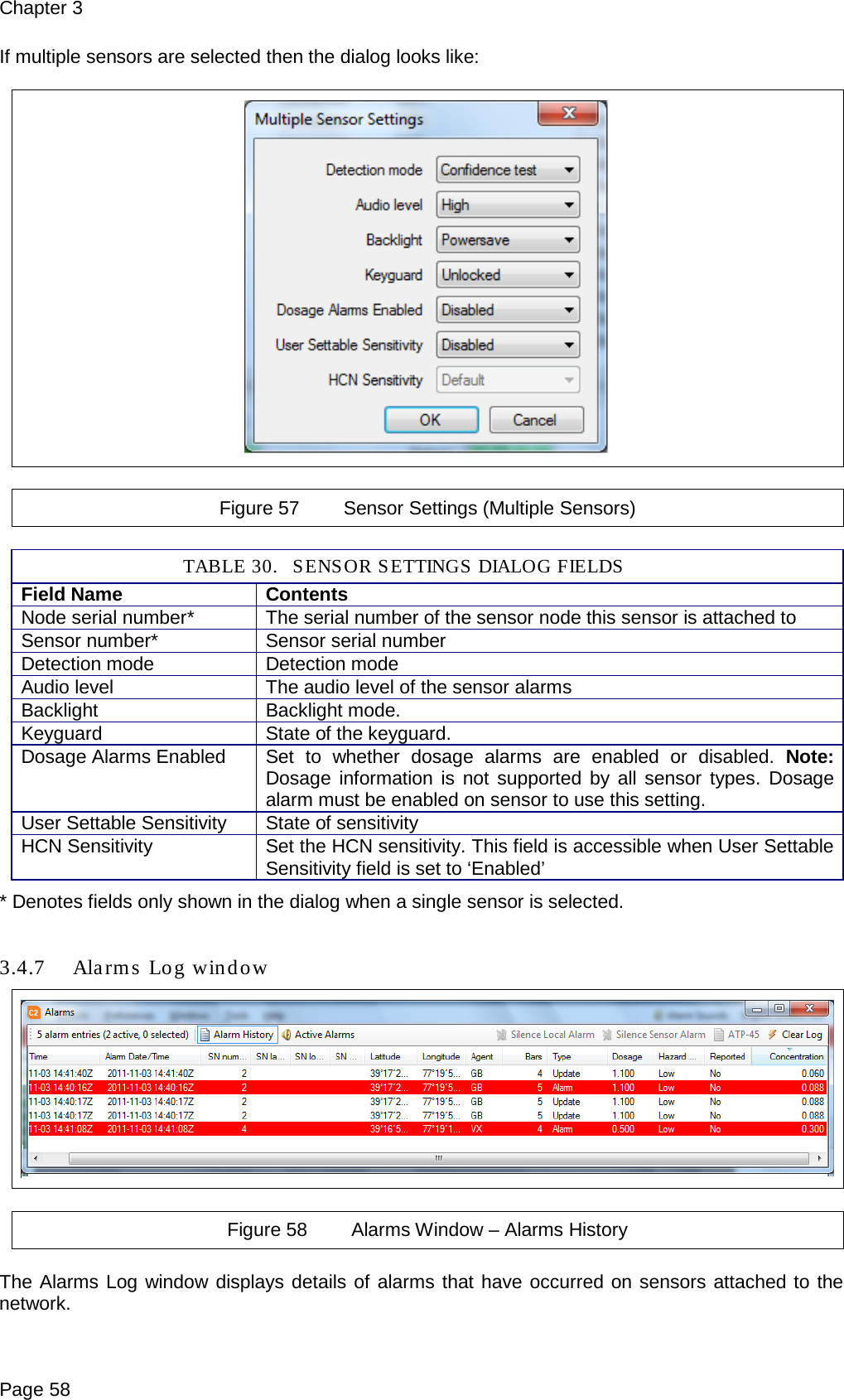
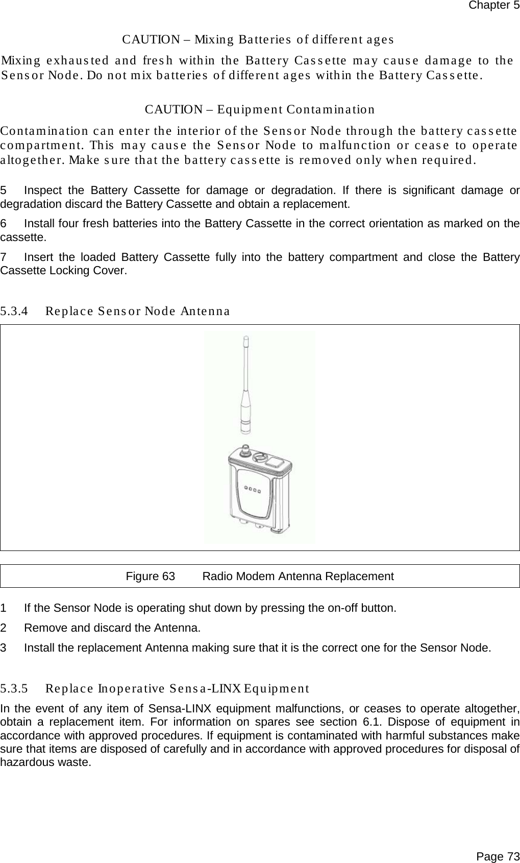
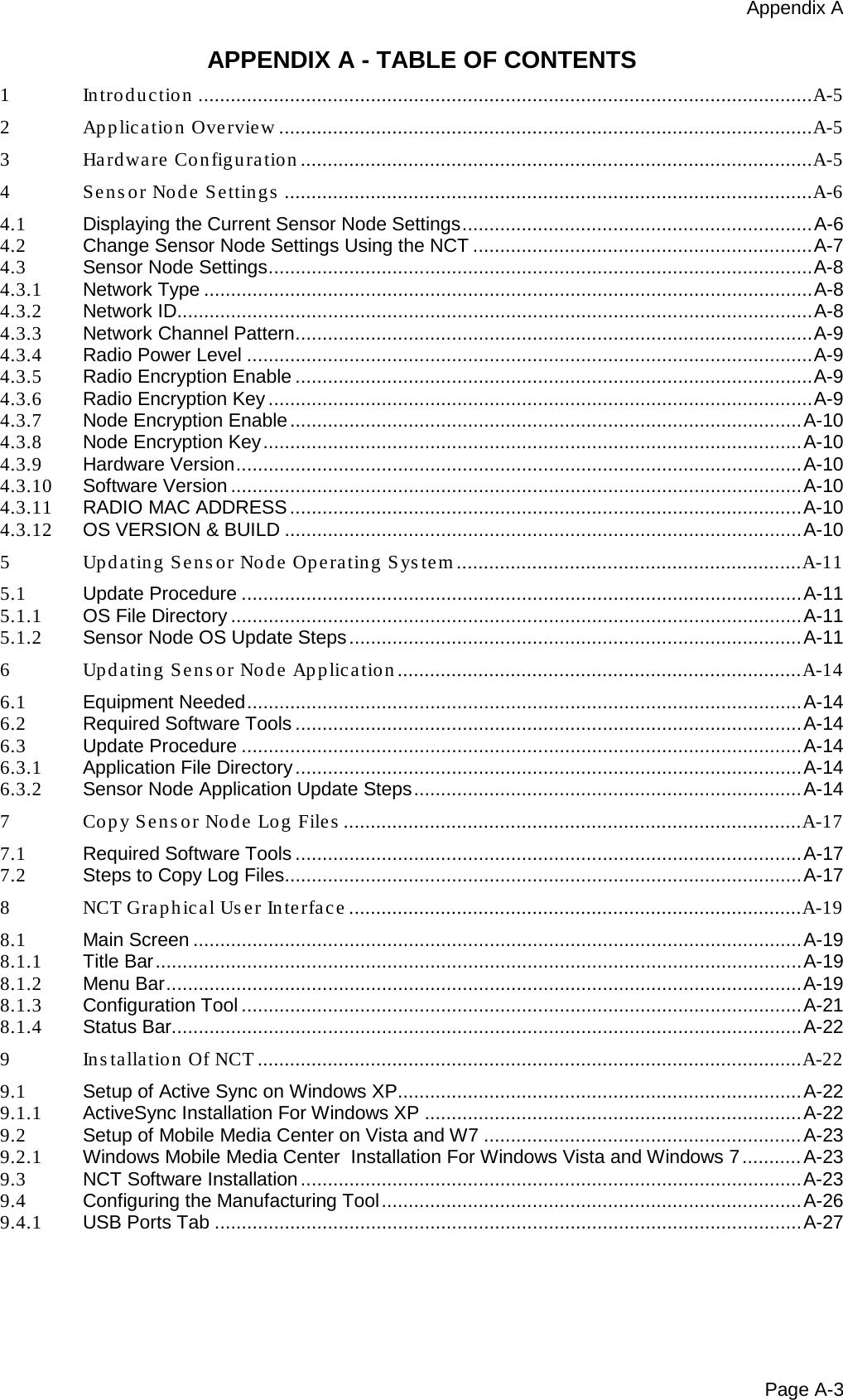
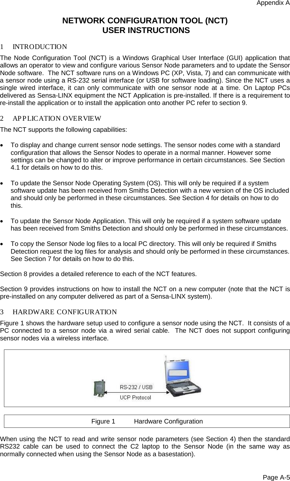
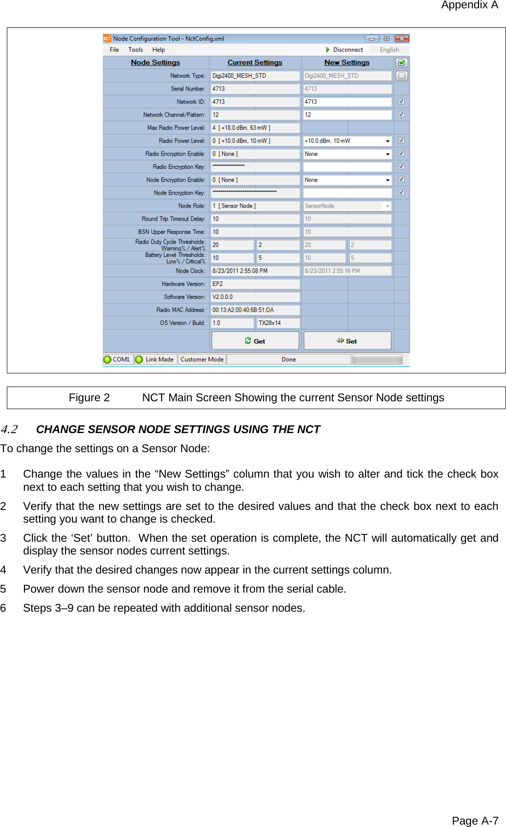
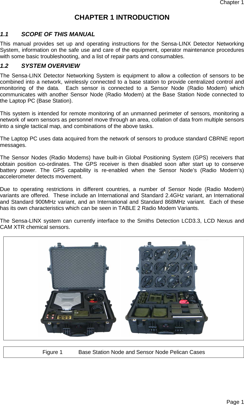
![Preliminary Pages Page iv CHAPTER 3 TECHNICAL DESCRIPTION ..................................................................................... 33 3.1 User Accounts on the C2 Laptop or Other Computers ..................................................... 33 3.2 Positioning factors for the Base Station Node .................................................................. 34 3.3 Positioning factors for the Sensor Node ........................................................................... 34 3.4 Detailed C2 Description ................................................................................................... 35 3.4.1 GUI Layout ...................................................................................................................... 35 3.4.2 Menus .............................................................................................................................. 37 3.4.3 Status bar ........................................................................................................................ 43 3.4.4 Sensor Node List ............................................................................................................. 45 3.4.5 Maps ................................................................................................................................ 47 3.4.6 Detail Panels ................................................................................................................... 49 3.4.7 Alarms Log window .......................................................................................................... 58 3.4.8 Warnings window ............................................................................................................. 60 3.4.9 Events window ................................................................................................................. 61 CHAP TER 4 INS TALLATION INFORMATION ............................................................................... 63 4.1 Sensa-LINX Software Install and Uninstall ....................................................................... 63 4.2 Sensa-LINX C2 and NCT Installation ............................................................................... 63 4.3 Uninstalling Sensa-LINX C2 and NCT ............................................................................. 64 4.4 Map Installation ................................................................................................................ 65 4.5 Uninstalling Maps ............................................................................................................ 65 CHAP TER 5 MAINTENANCE INFORMATION an d INSTRUCTIONS ............................................ 67 5.1 General ............................................................................................................................ 67 5.2 Preventive Maintenance .................................................................................................. 67 5.2.1 General Cleaning ............................................................................................................. 68 5.3 Corrective Maintenance ................................................................................................... 68 5.3.1 Equipment Decontamination ............................................................................................ 69 5.3.2 Post Decontamination Checks ......................................................................................... 71 5.3.3 Replace Sensor Node Batteries or Battery Cassette ........................................................ 71 5.3.4 Replace Sensor Node Antenna ........................................................................................ 73 5.3.5 Replace Inoperative Sensa-LINX Equipment ................................................................... 73 5.4 Fault Analysis .................................................................................................................. 74 5.4.1 Fault Diagnosis ................................................................................................................ 74 5.4.2 Fault Messages ............................................................................................................... 77 CHAPTER 6 SPARES INFORMATION .......................................................................................... 79 6.1 General ............................................................................................................................ 79 APPENDIX A ................................................................................................................................ A-1 Network Configuration Tool (NCT) User Instructions .............................................................. A-5 TABLE OF FIGURES Figure 1 Base Station Node and Sensor Node Pelican Cases ..................................................... 1 Figure 2 Laptop PC ...................................................................................................................... 3 Figure 3 Sensor Node (Radio Modem) ......................................................................................... 4 Figure 4 Detector to SN Comms Cable (20172) ........................................................................... 7 Figure 5 Laptop PC to BSN Comms Cable (20173) ..................................................................... 7 Figure 6 Short Spiral Comms Cable (20175)................................................................................ 7 Figure 7 Spiral Comms Cable (20234) ......................................................................................... 8 Figure 8 Mains Power Cable (5356-5085) .................................................................................... 8 Figure 9 Mains Travel Adaptor (3370-2506) ................................................................................. 8 Figure 10 Power and Comms Cable (20553) ................................................................................. 9 Figure 11 DC-DC Transformer(3330-5120) .................................................................................... 9 Figure 12 AC-DC Transformer (20734 [Green] or 20734A [Black]) ................................................ 9 Figure 13 Nexus Mounting Bracket (20466) ................................................................................. 10](https://usermanual.wiki/Smiths-Detection/2039924.User-Manual/User-Guide-1664813-Page-6.png)
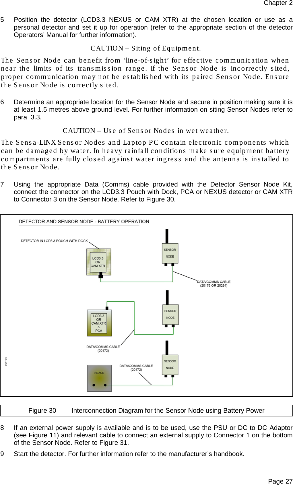
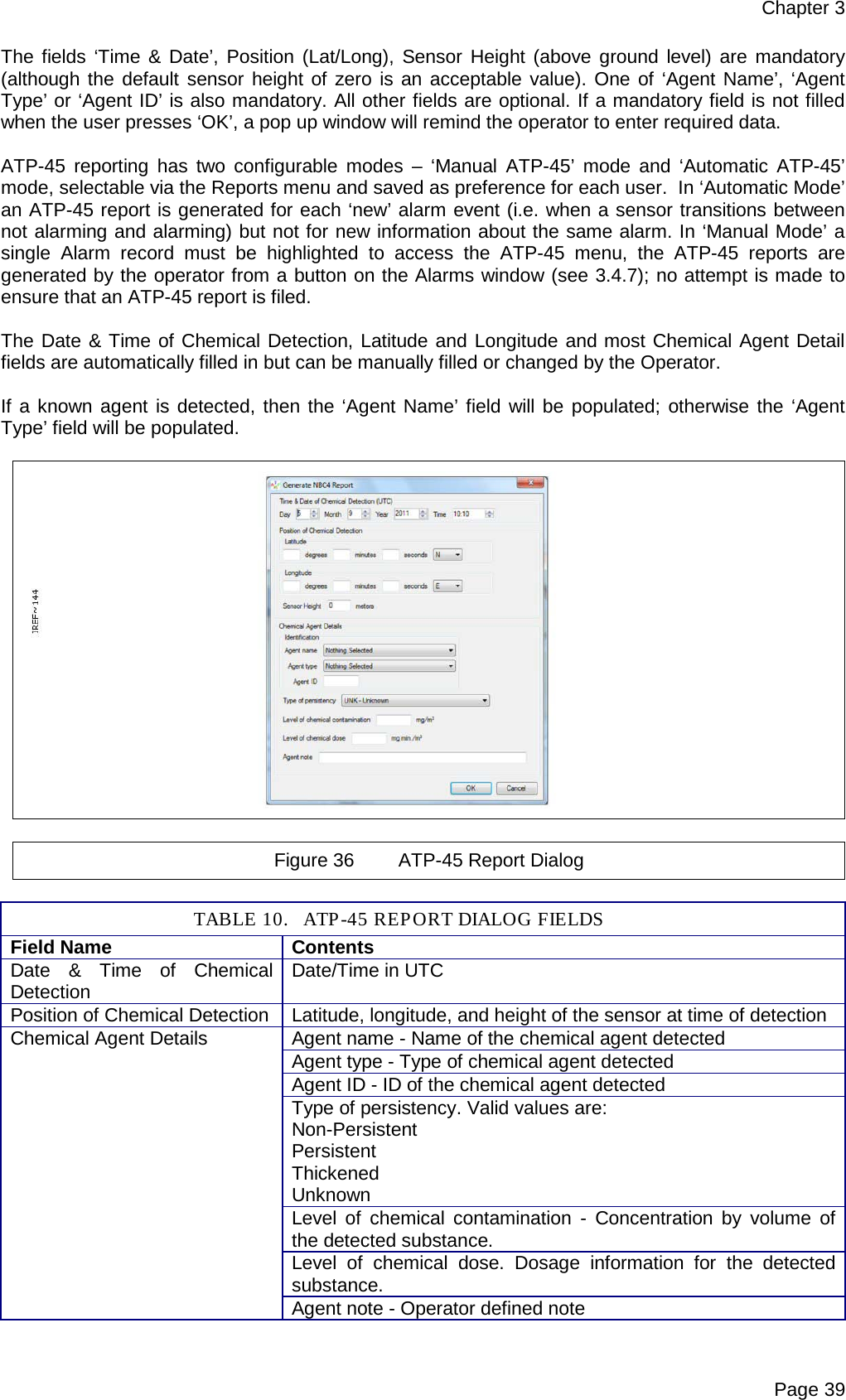
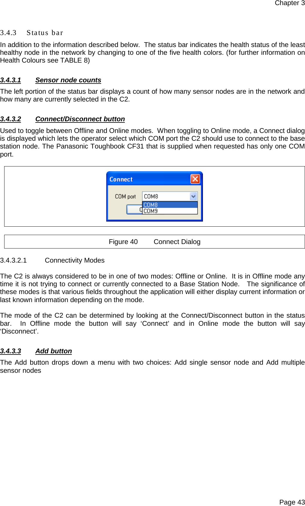
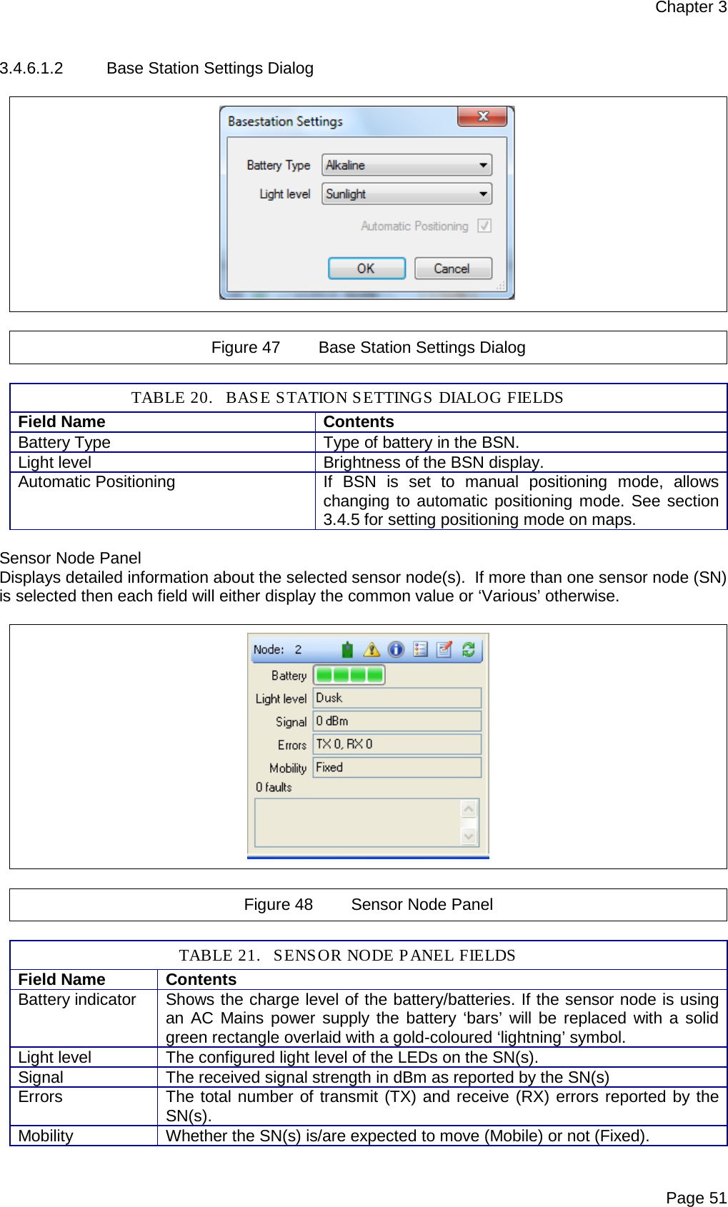
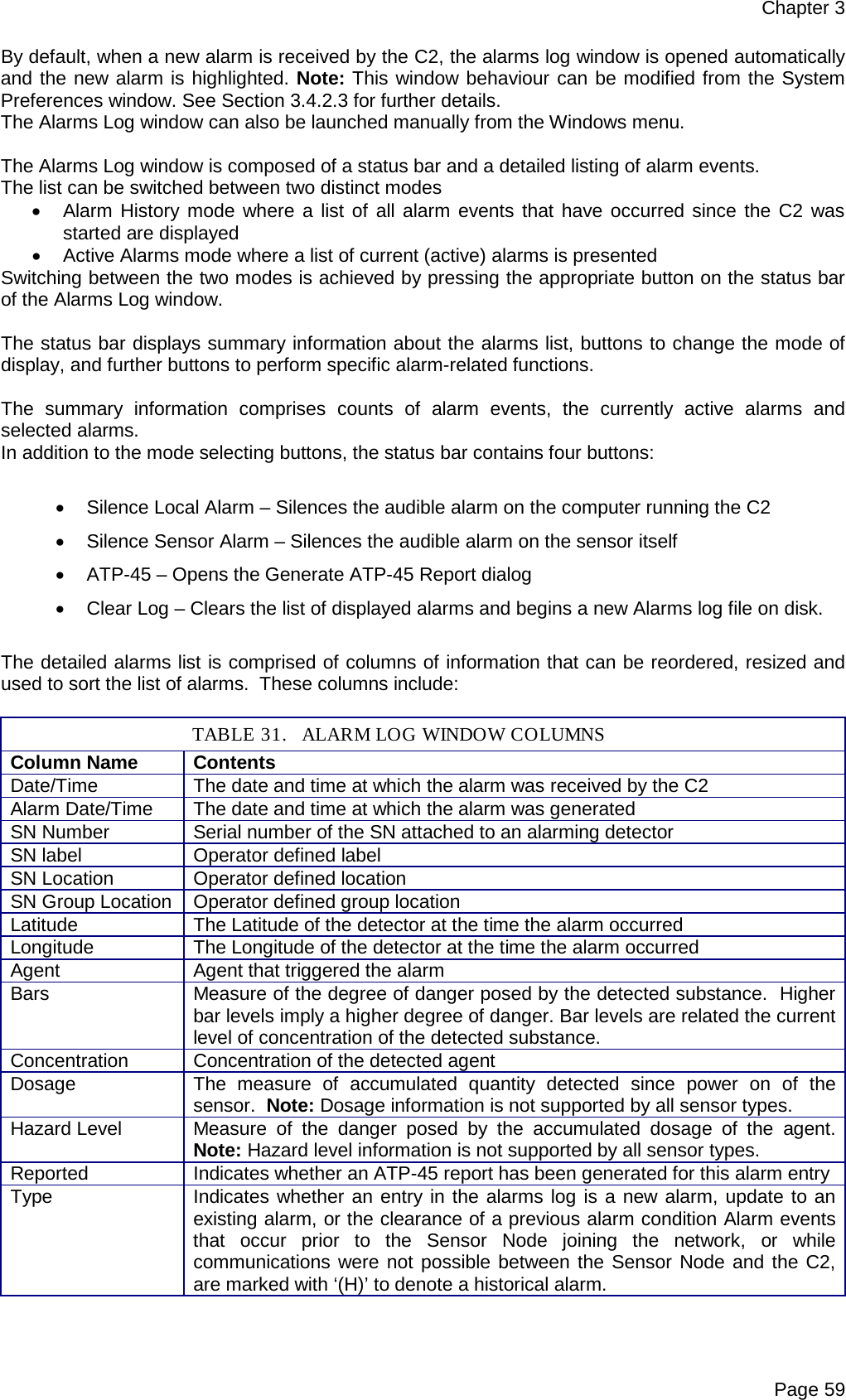
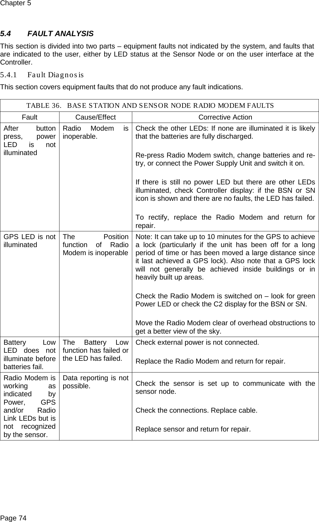
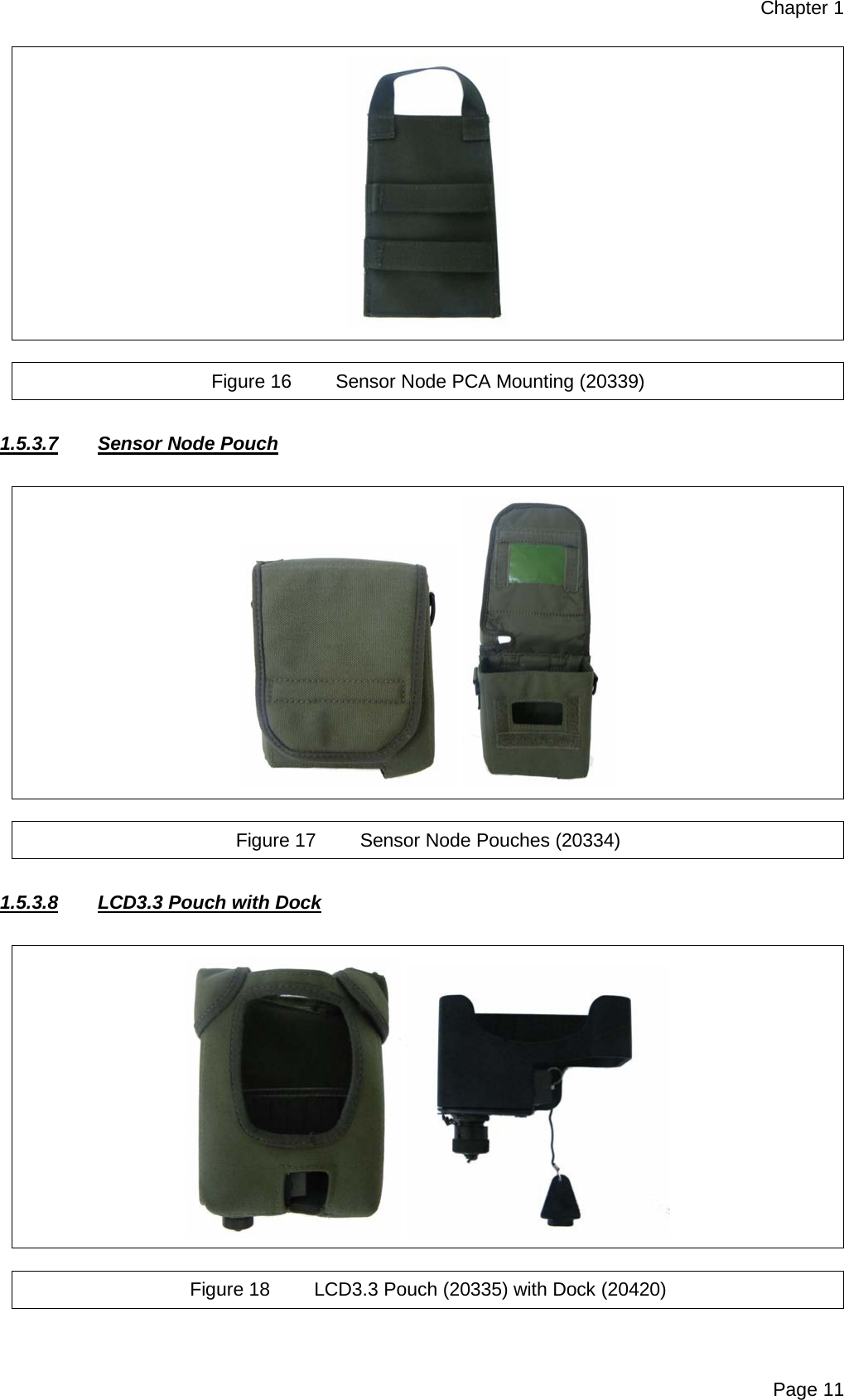
![Preliminary Pages Page v Figure 14 PCA Mounting Bracket (20336) ................................................................................... 10 Figure 15 Tripod Mounting Bracket (20330) ................................................................................. 10 Figure 16 Sensor Node PCA Mounting (20339) ........................................................................... 11 Figure 17 Sensor Node Pouches (20334) .................................................................................... 11 Figure 18 LCD3.3 Pouch (20335) with Dock (20420) ................................................................... 11 Figure 19 Shoulder Strap (5368-9020 [Green] or 19268 [Black]) ................................................. 12 Figure 20 Mounting Strap (20735 [Green] or 20735A [Black])...................................................... 12 Figure 21 Tripod (6881-0216) ...................................................................................................... 12 Figure 22 Laptop PC ................................................................................................................... 15 Figure 23 Radio Modem .............................................................................................................. 16 Figure 24 Pull-The-Dot Fastening ................................................................................................ 18 Figure 25 Interconnection Diagram for Base Station Node using Battery Power .......................... 23 Figure 26 Connect Button – C2 Program Main Window ............................................................... 24 Figure 27 Base Station Sensor Node Detail Panel ....................................................................... 24 Figure 28 ‘Open Map File’ Button ................................................................................................ 25 Figure 29 Map / Image file dialog ................................................................................................. 25 Figure 30 Interconnection Diagram for the Sensor Node using Battery Power ............................. 27 Figure 31 Interconnection Diagram for the Sensor Node using Mains Power .............................. 28 Figure 32 Alarm Pop-up Window ................................................................................................. 29 Figure 33 Windows ‘Help and Support’ ........................................................................................ 33 Figure 34 Power Management Pop-up Window ........................................................................... 33 Figure 35 Sensa-LINX C2 Main Window...................................................................................... 35 Figure 36 ATP-45 Report Dialog .................................................................................................. 39 Figure 37 Folder Options Dialog .................................................................................................. 40 Figure 38 System Preferences Dialog ......................................................................................... 41 Figure 39 Map Icons Legend Window .......................................................................................... 42 Figure 40 Connect Dialog ............................................................................................................ 43 Figure 41 Add Single Sensor Node Dialog ................................................................................... 44 Figure 42 Add multiple Sensor Nodes Dialog .............................................................................. 44 Figure 43 Sensor Node List ......................................................................................................... 45 Figure 44 Map Panel ................................................................................................................... 47 Figure 45 Base Station Panel ...................................................................................................... 49 Figure 46 Base Station Information Window ................................................................................ 50 Figure 47 Base Station Settings Dialog ....................................................................................... 51 Figure 48 Sensor Node Panel ...................................................................................................... 51 Figure 49 Sensor Node Information Window ............................................................................... 52 Figure 50 Sensor Node Tags Dialog ............................................................................................ 53 Figure 51 Multiple Sensor Node Tags Dialog ............................................................................... 54 Figure 52 Sensor Node Settings Dialog ....................................................................................... 54 Figure 53 Multiple Sensor Node Settings Dialog .......................................................................... 54 Figure 54 Sensor Panel ............................................................................................................... 55 Figure 55 Sensor Information Window ......................................................................................... 57 Figure 56 Sensor Settings ........................................................................................................... 57 Figure 57 Sensor Settings (Multiple Sensors) .............................................................................. 58 Figure 58 Alarms Window – Alarms History ................................................................................. 58 Figure 59 Alarms Window – Active Alarms .................................................................................. 60 Figure 60 Warnings Window ........................................................................................................ 60 Figure 61 Events Window ............................................................................................................ 61 Figure 62 Sensor Node Batteries or Battery Cassette Replacement ............................................ 71 Figure 63 Radio Modem Antenna Replacement .......................................................................... 73 Figure 1 Hardware Configuration .............................................................................................. A-5 Figure 2 NCT Main Screen Showing the current Sensor Node settings .................................... A-7 Figure 3 Destination Folder Access Denied Dialog ................................................................. A-11 Figure 4 Reprogram Warning Dialog ...................................................................................... A-12 Figure 5 Starting OS Update Dialog ........................................................................................ A-12 Figure 6 Loader Error Dialog .................................................................................................. A-12 Figure 7 MfgTool Main Screen ................................................................................................ A-12 Figure 8 MfgTool Connected .................................................................................................. A-13 Figure 9 MfgTool Busy ............................................................................................................ A-13](https://usermanual.wiki/Smiths-Detection/2039924.User-Manual/User-Guide-1664813-Page-7.png)


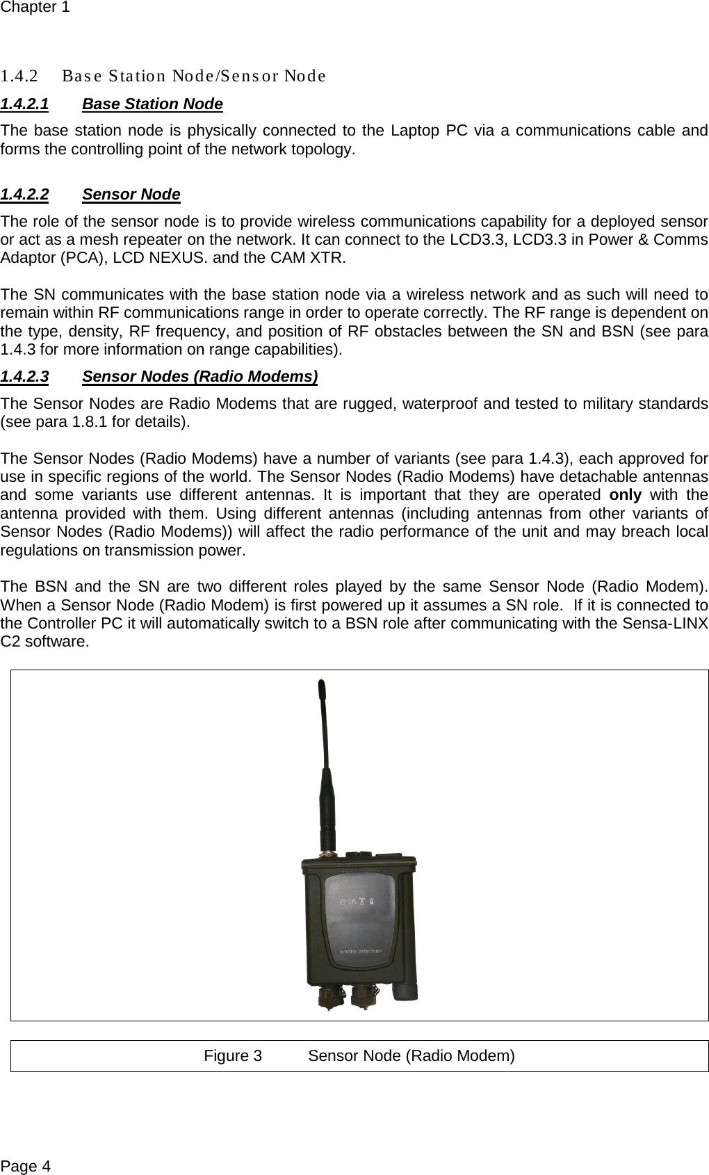
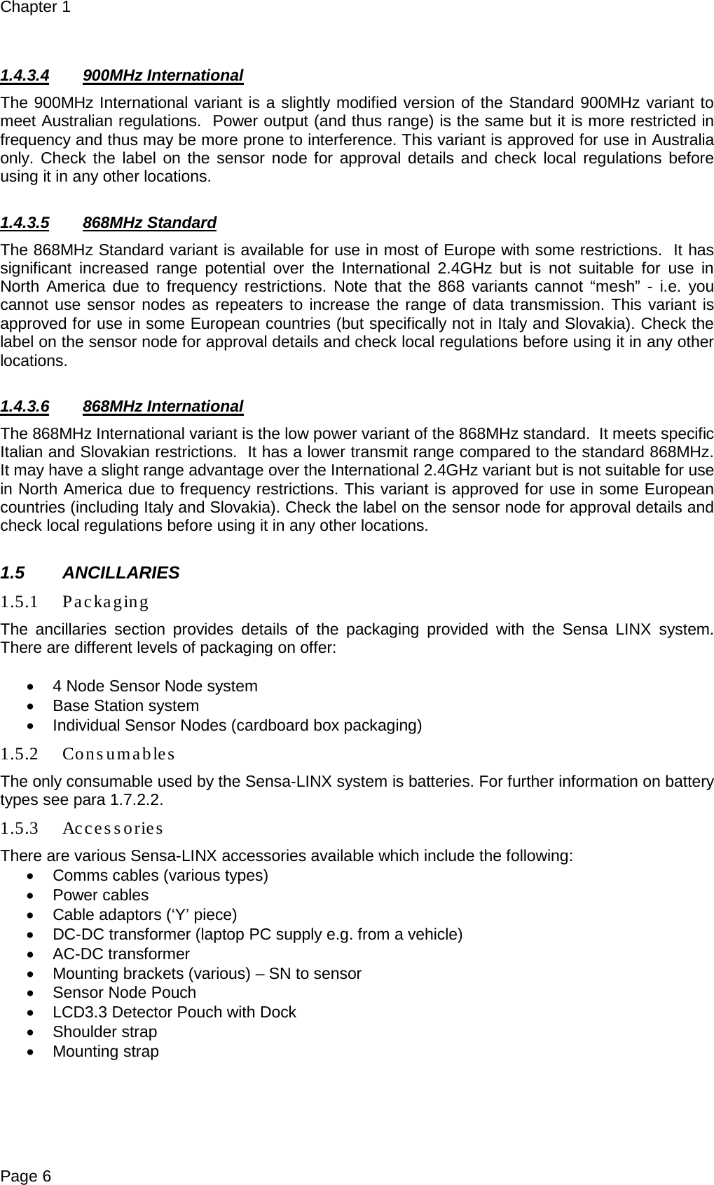
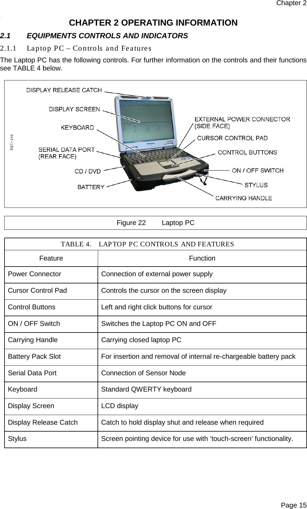
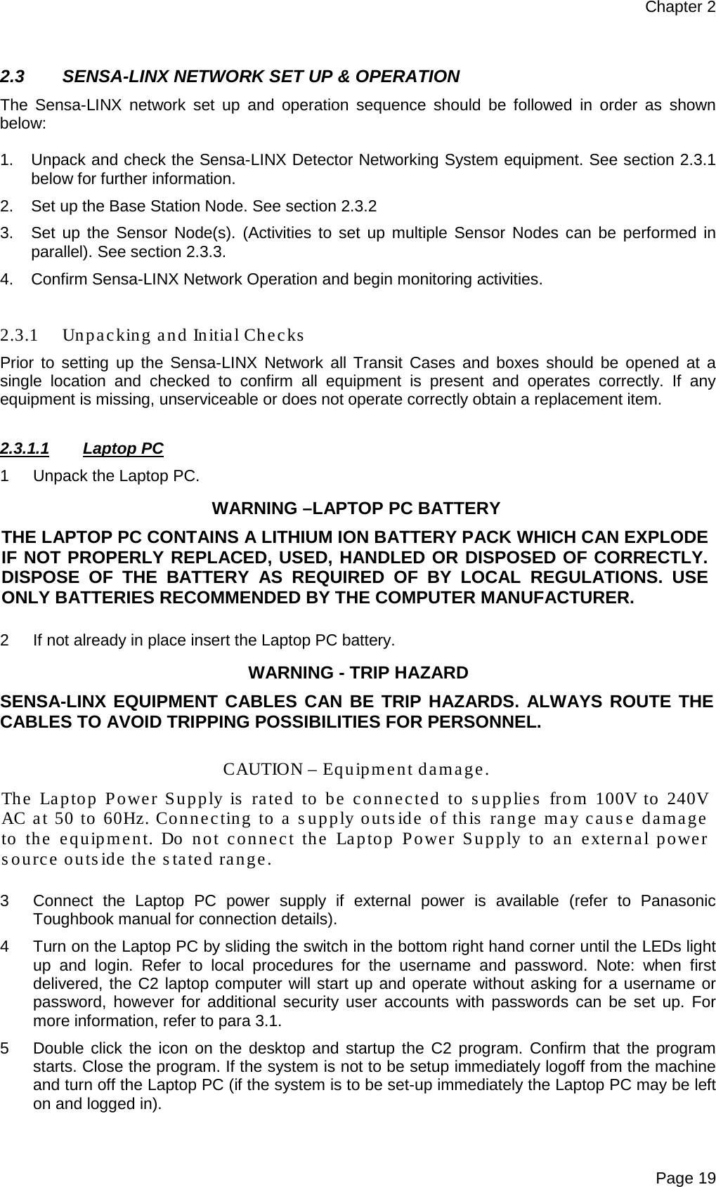
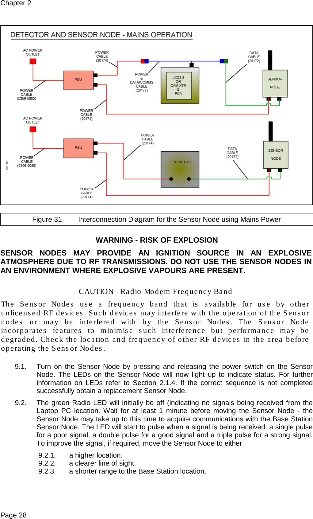
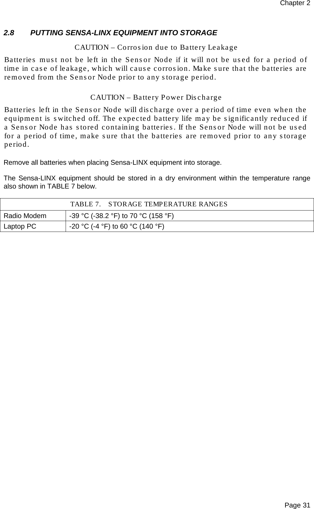
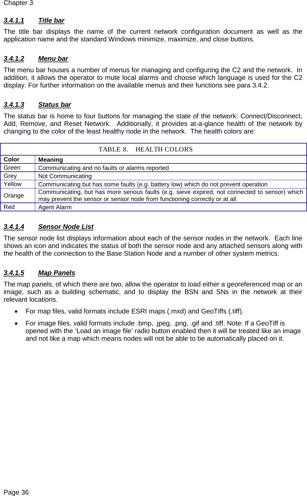
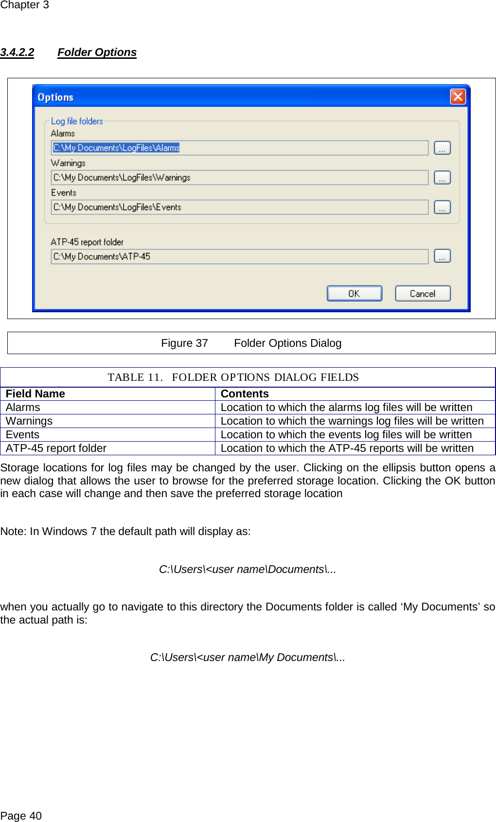
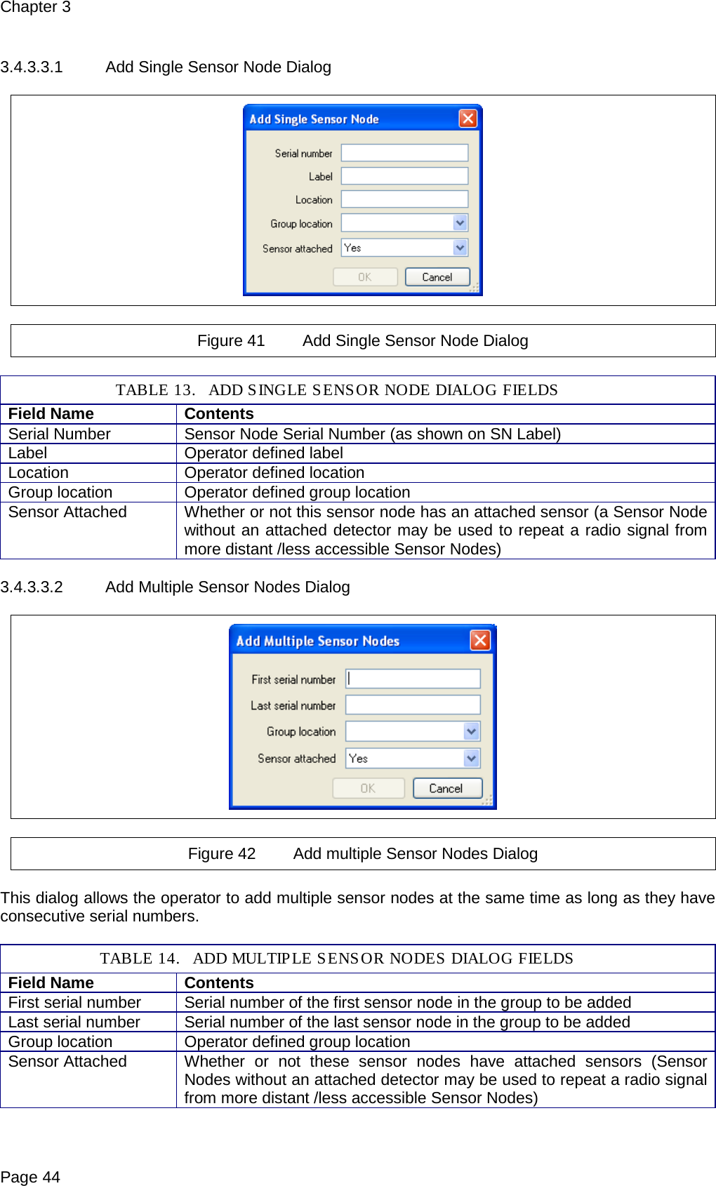
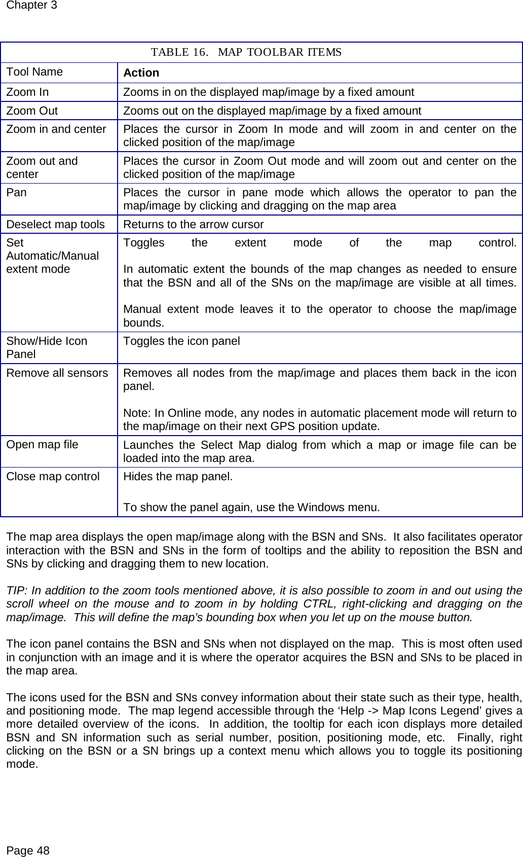
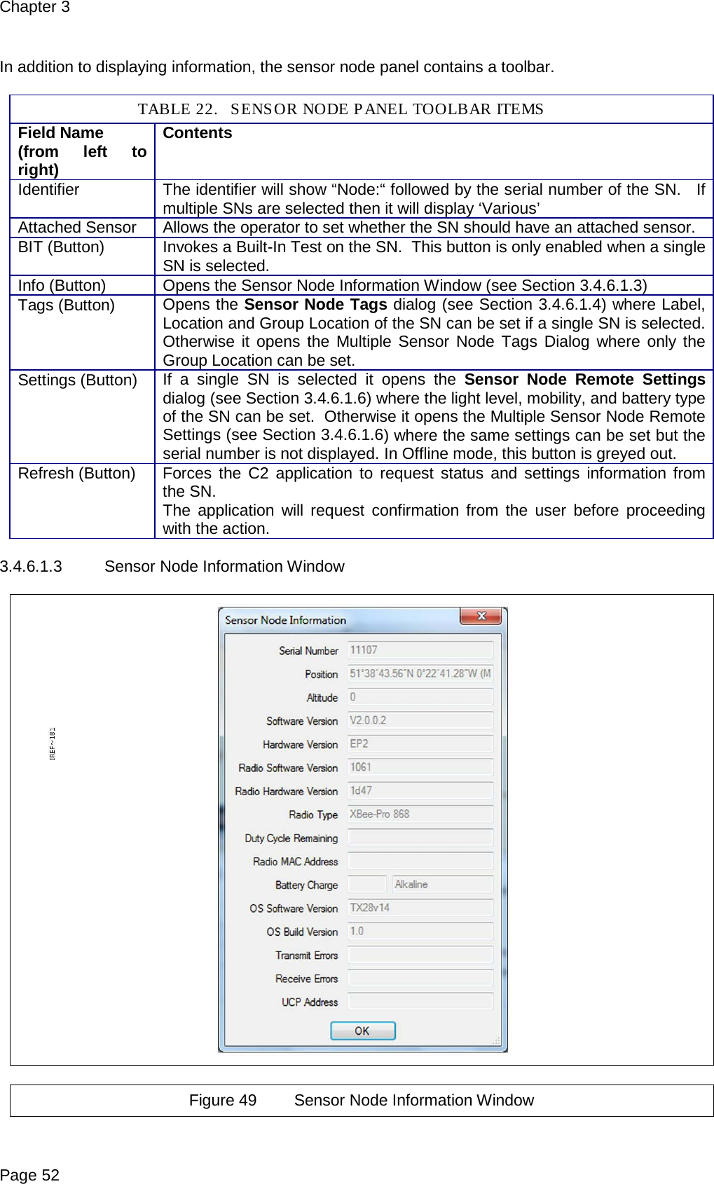
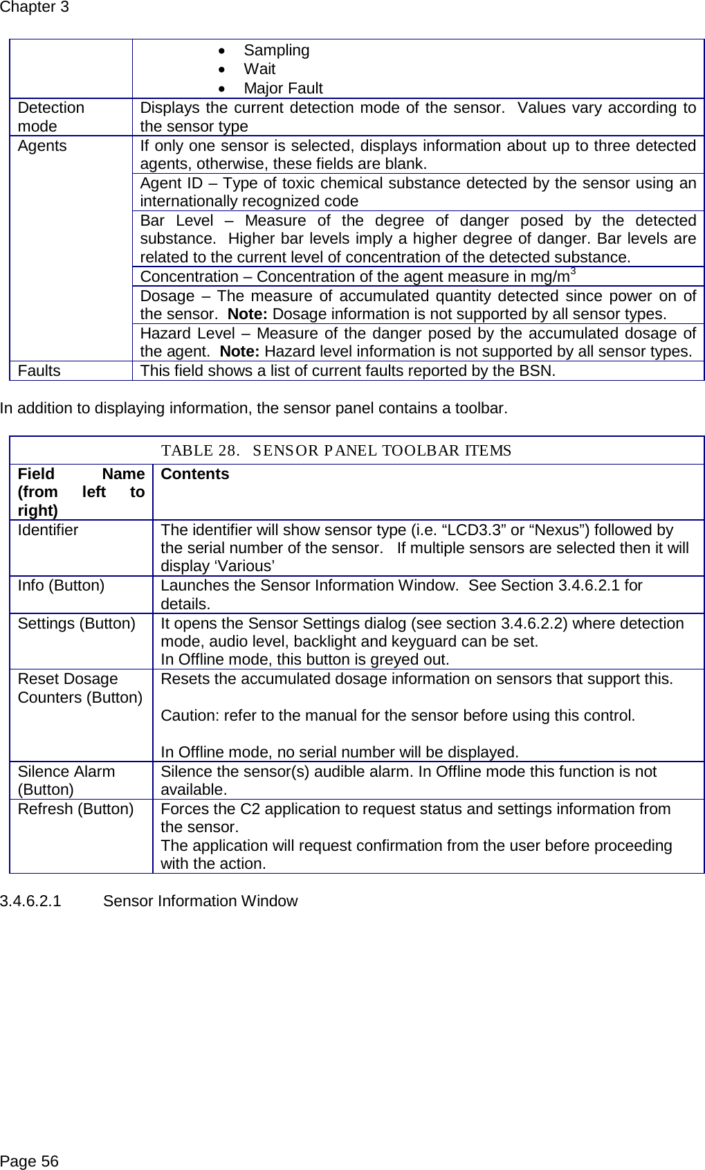
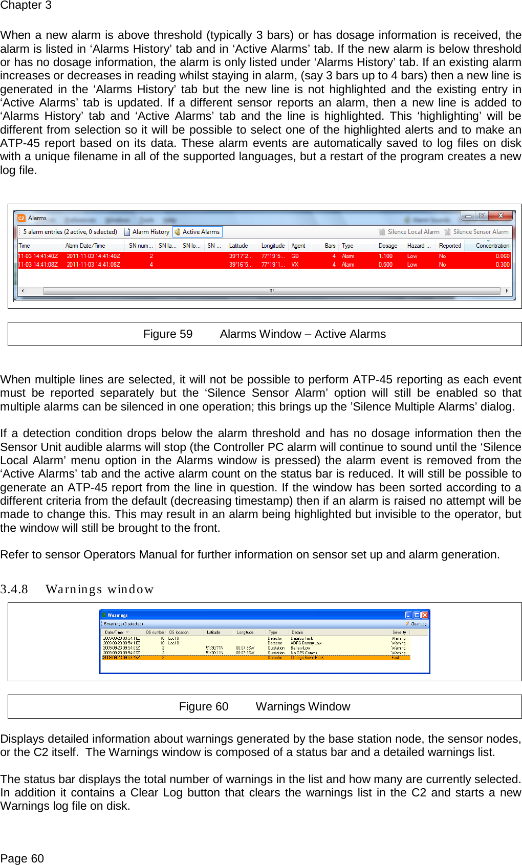
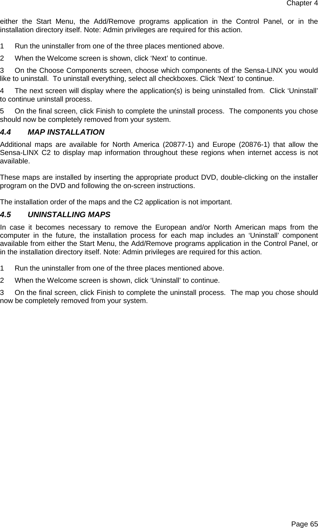
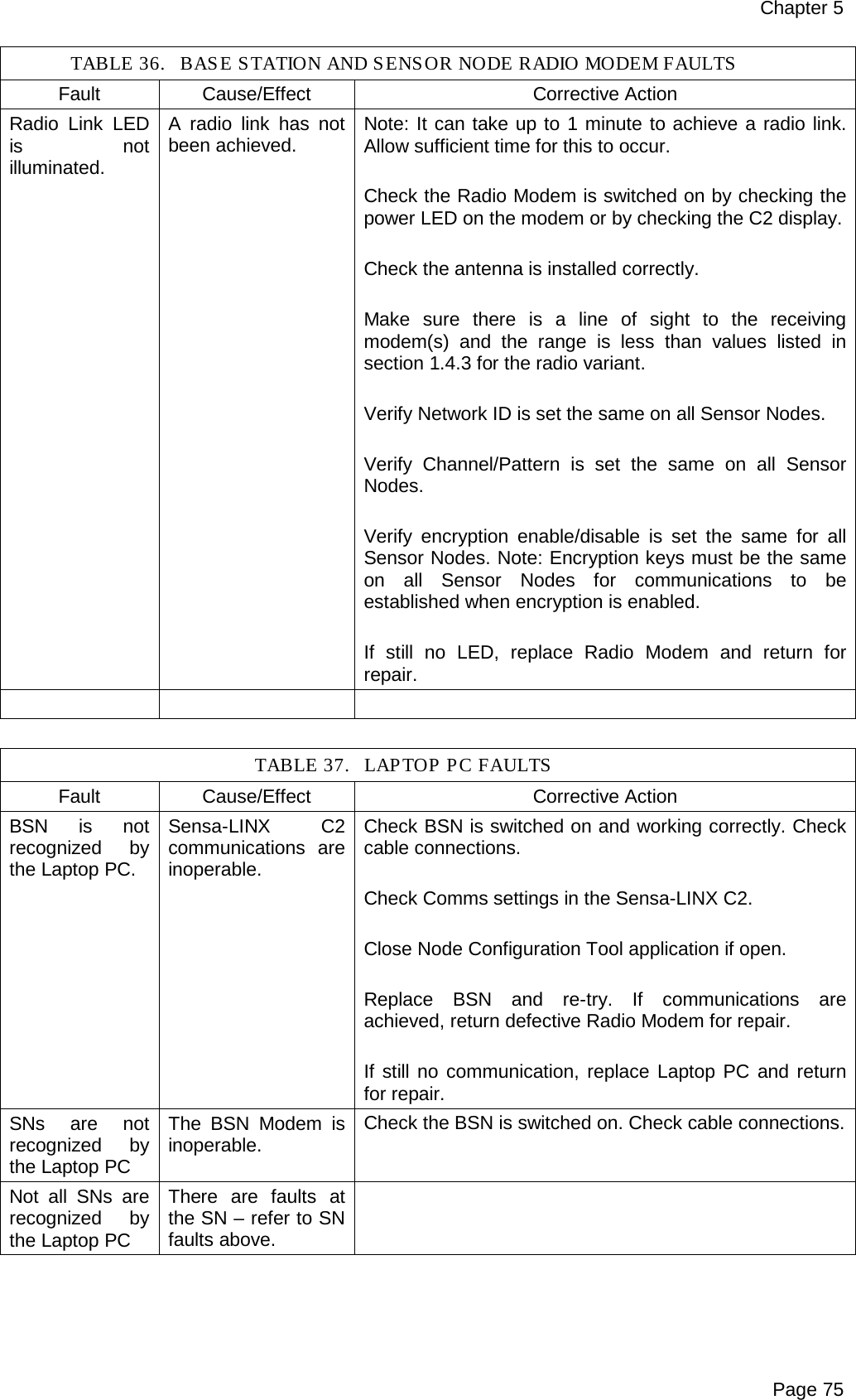
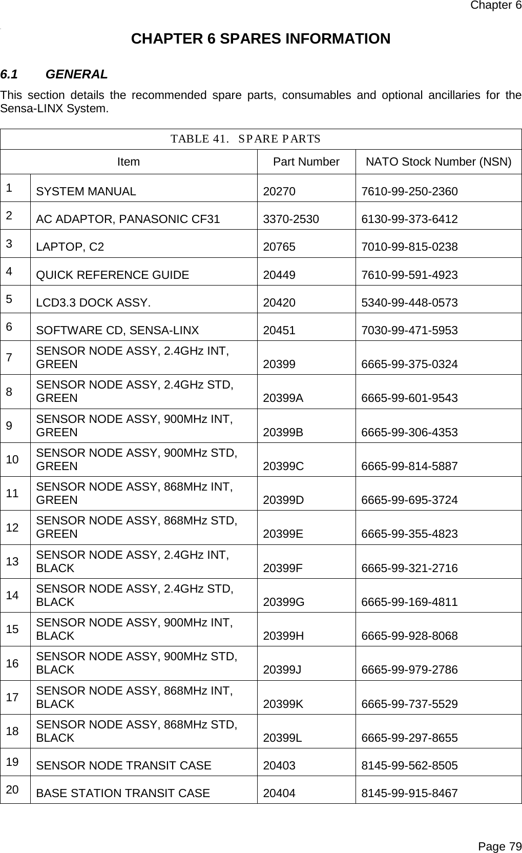
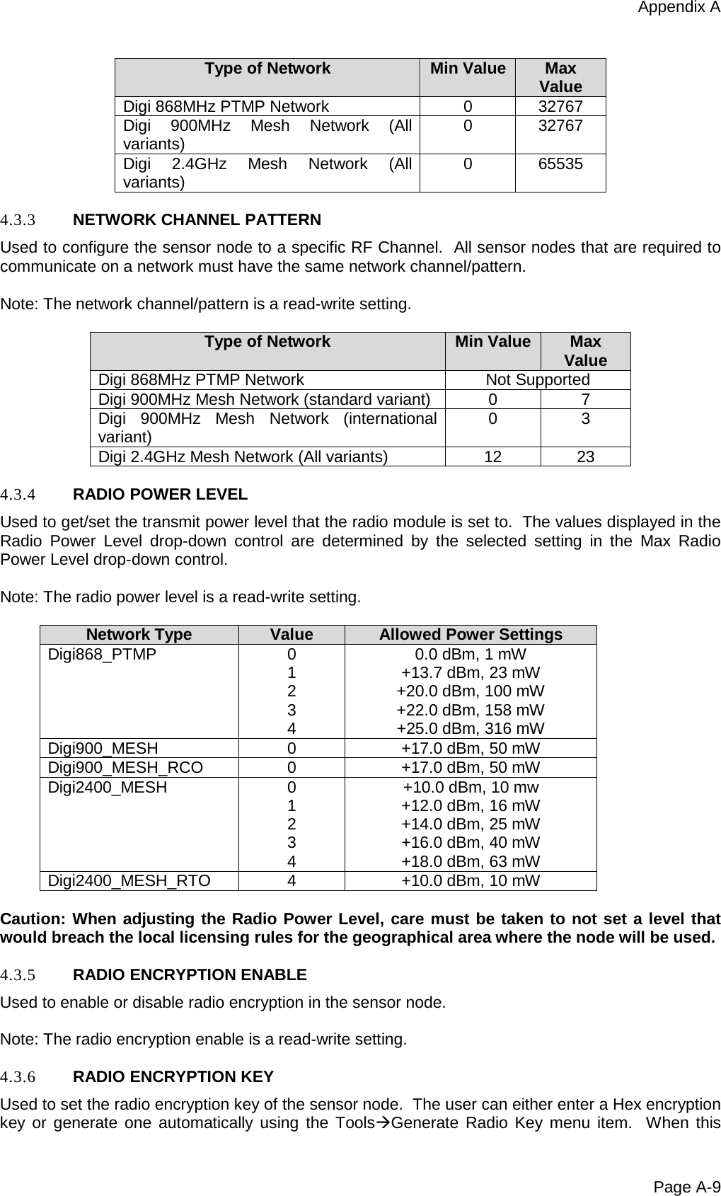
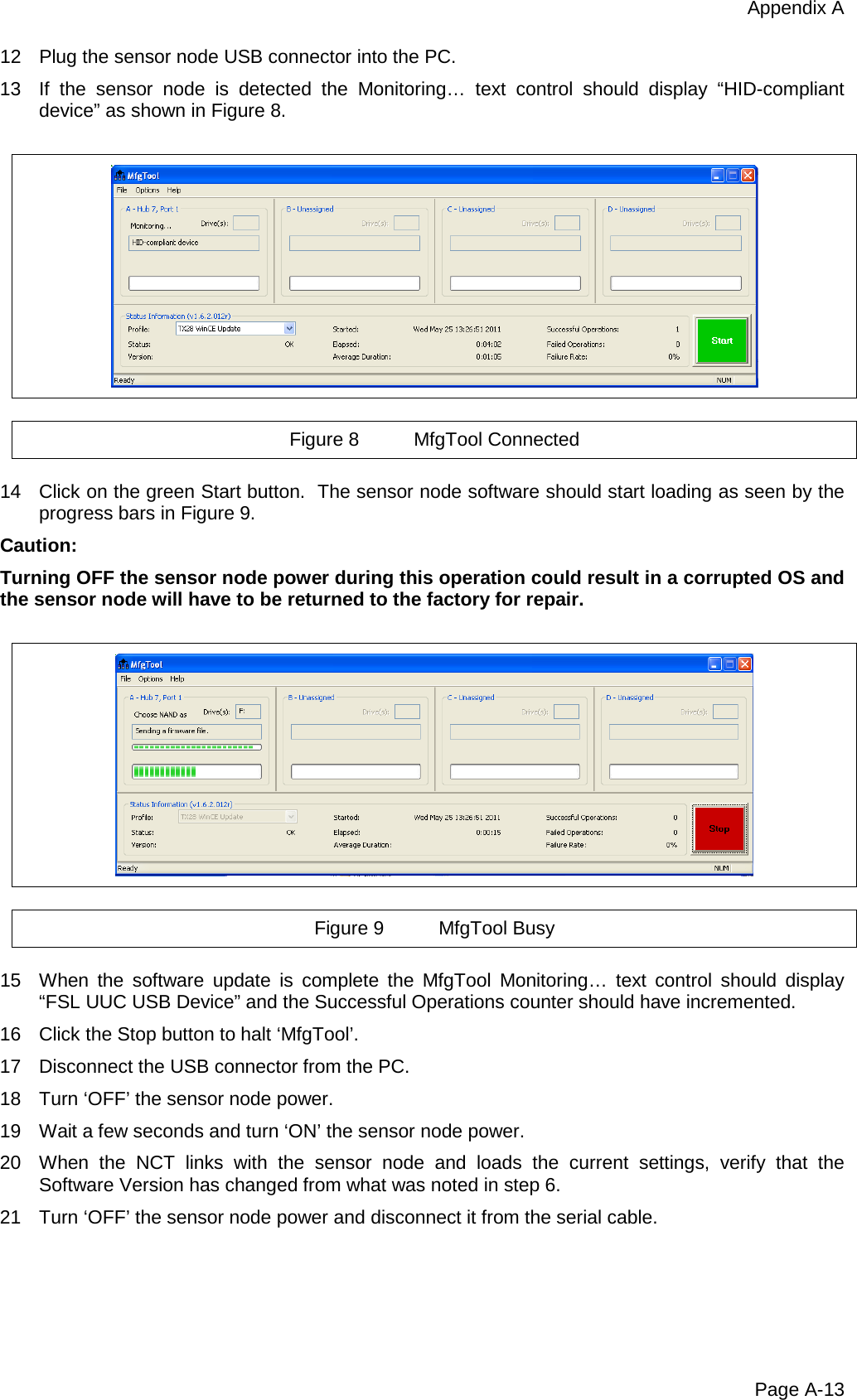
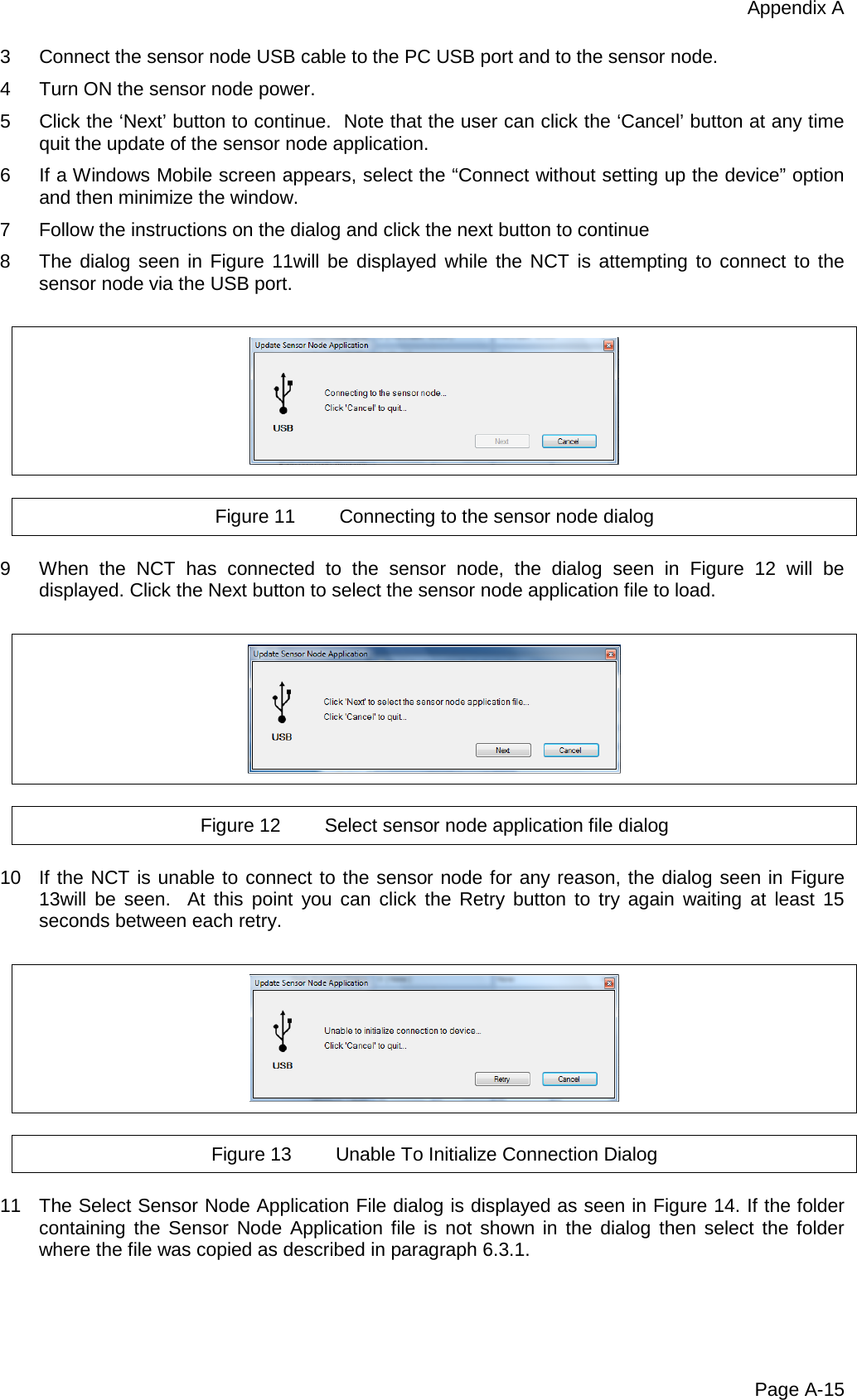
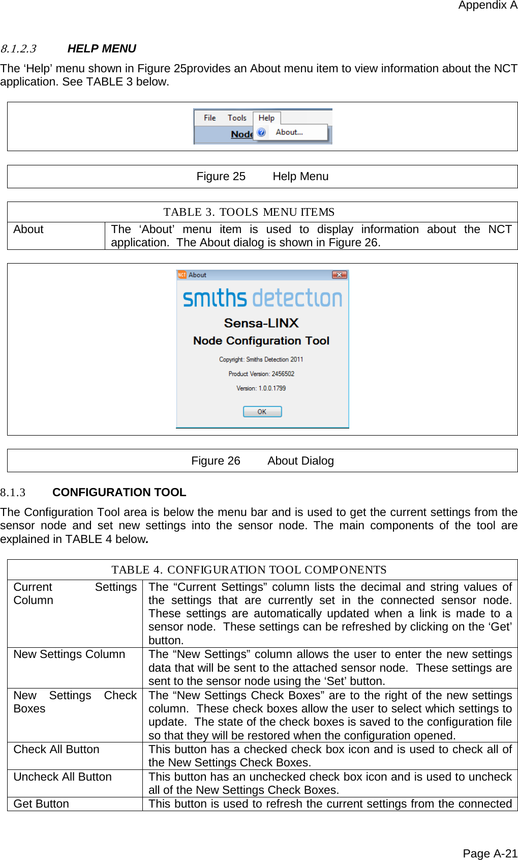
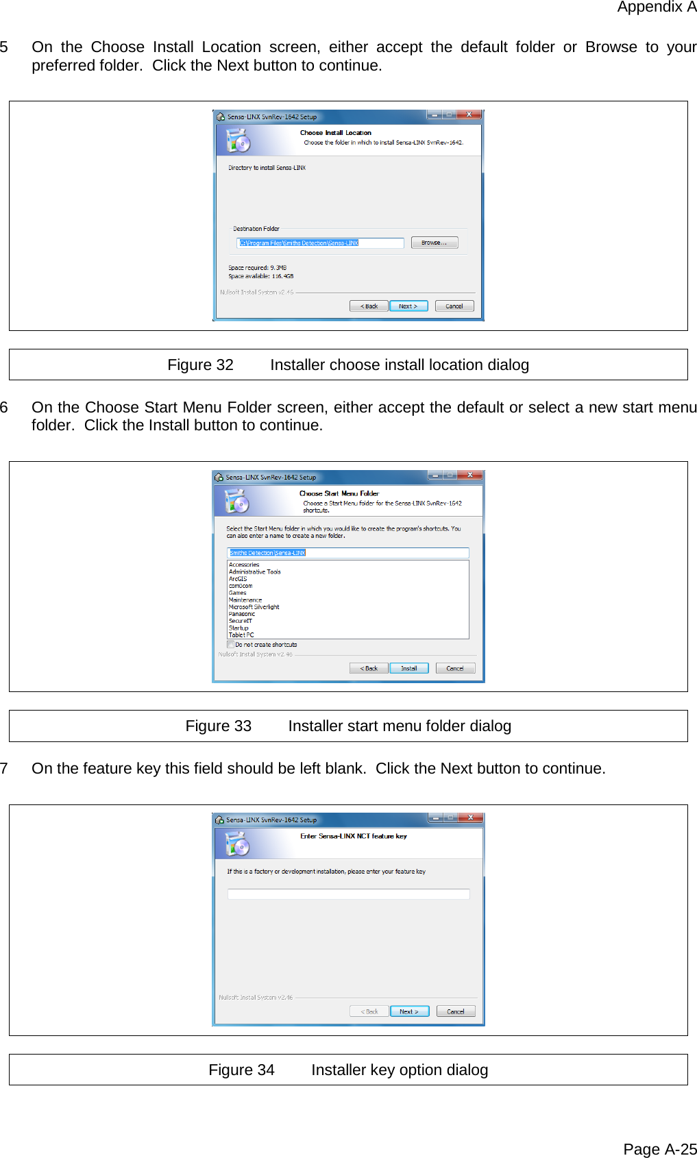
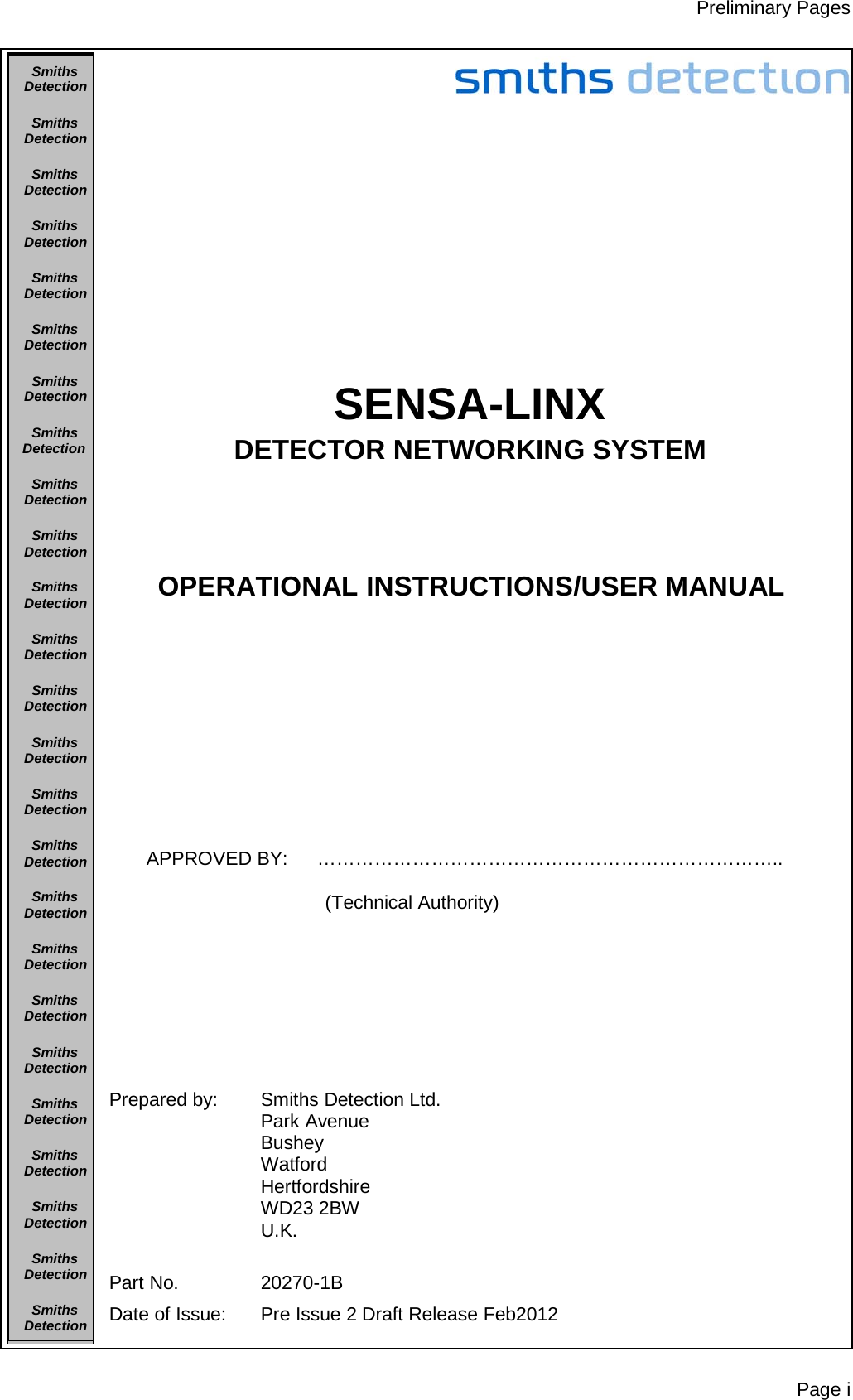
![Chapter 1 Page 9 1.5.3.3 Combined Power & Comms Cable Figure 10 Power and Comms Cable (20553) 1.5.3.4 DC-DC Transformer Figure 11 DC-DC Transformer(3330-5120) 1.5.3.5 AC-DC Transformer Figure 12 AC-DC Transformer (20734 [Green] or 20734A [Black])](https://usermanual.wiki/Smiths-Detection/2039924.User-Manual/User-Guide-1664813-Page-29.png)
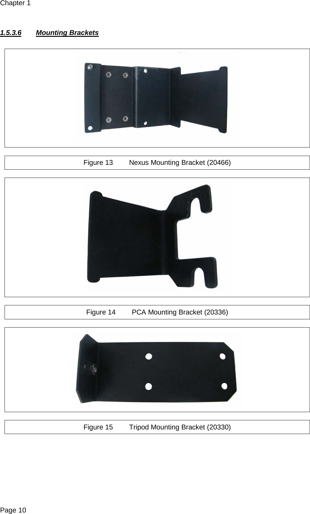
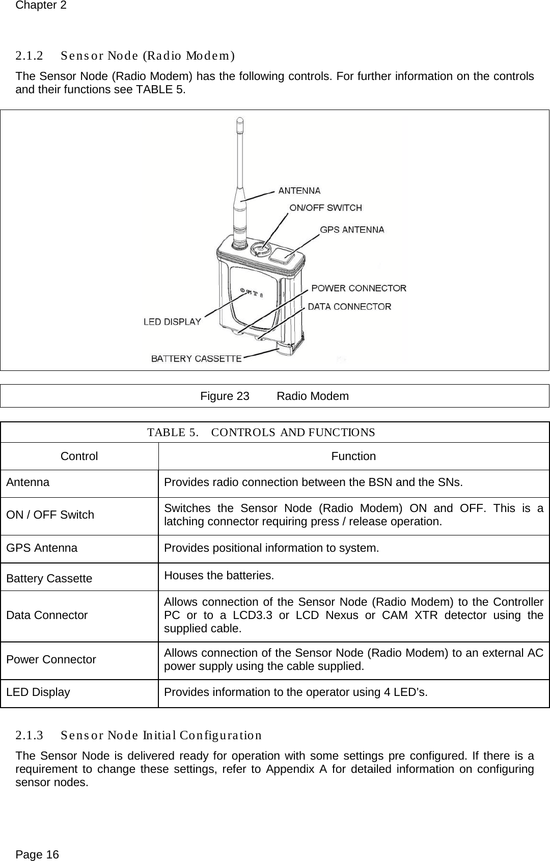
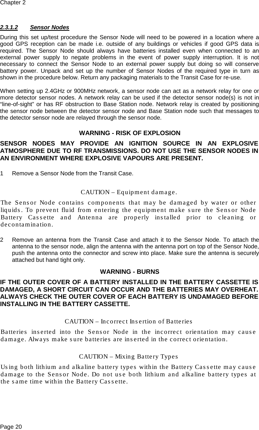
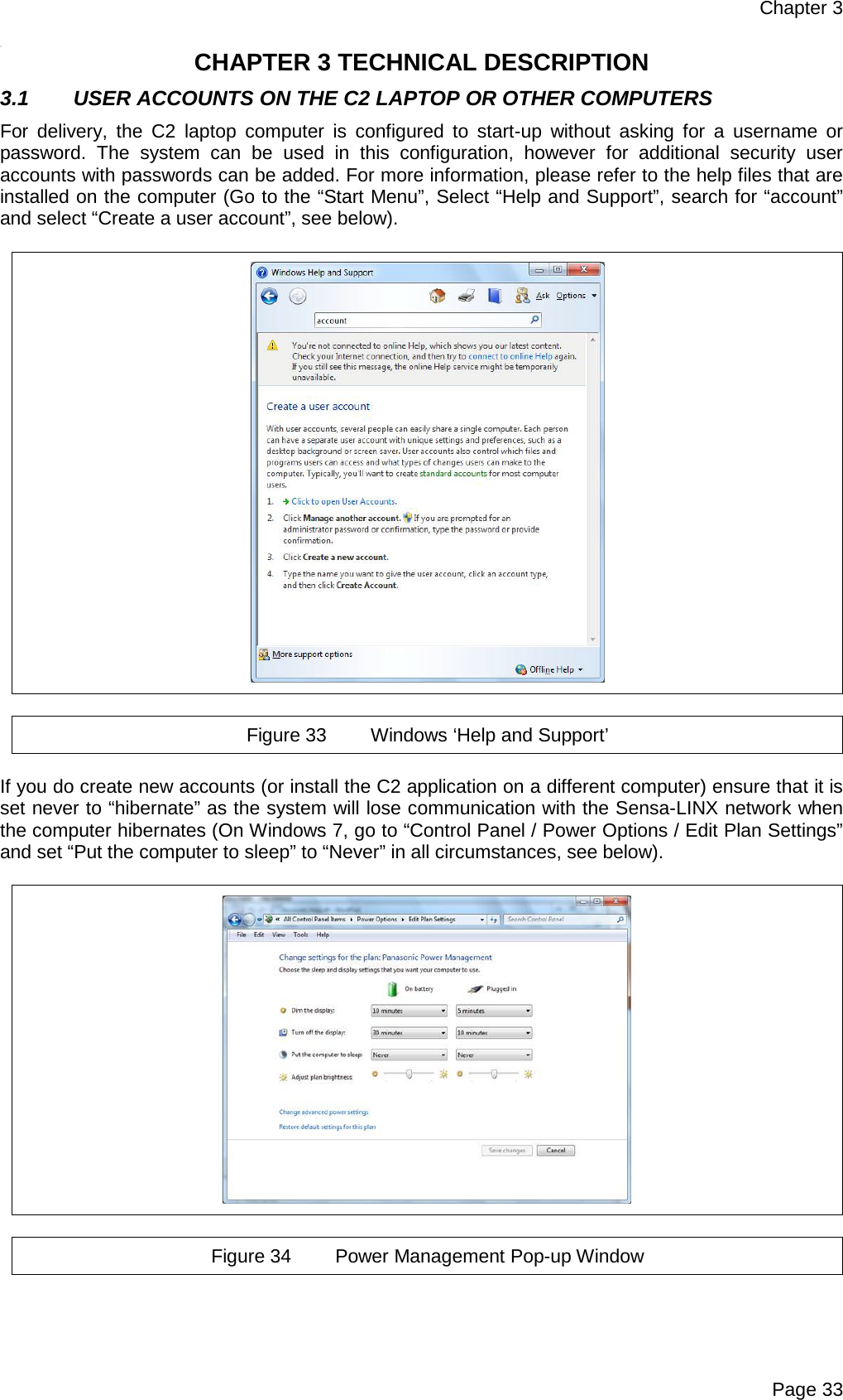
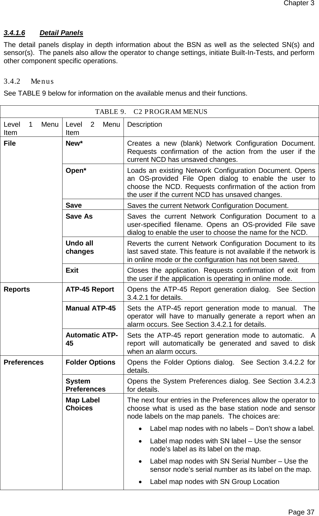
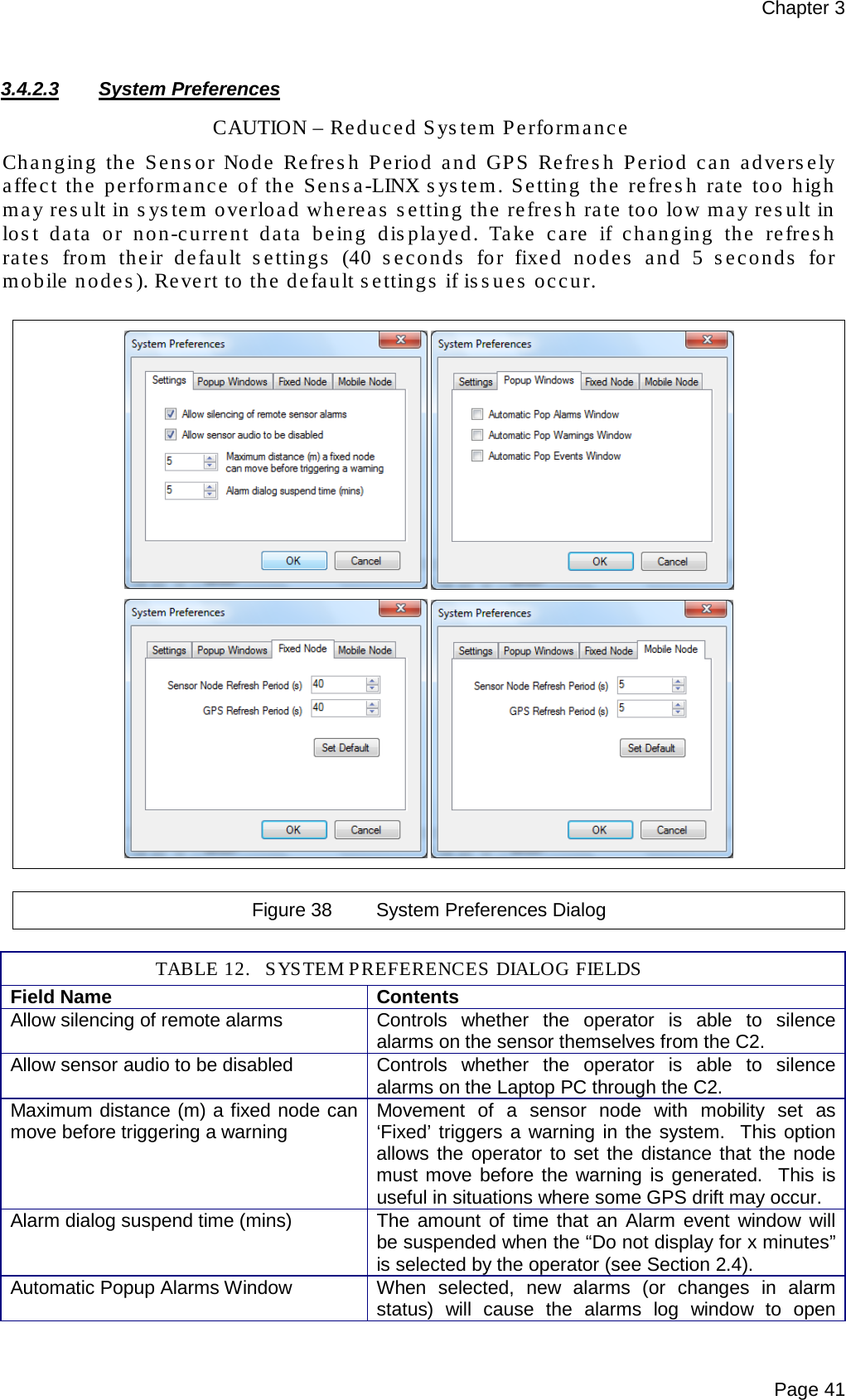
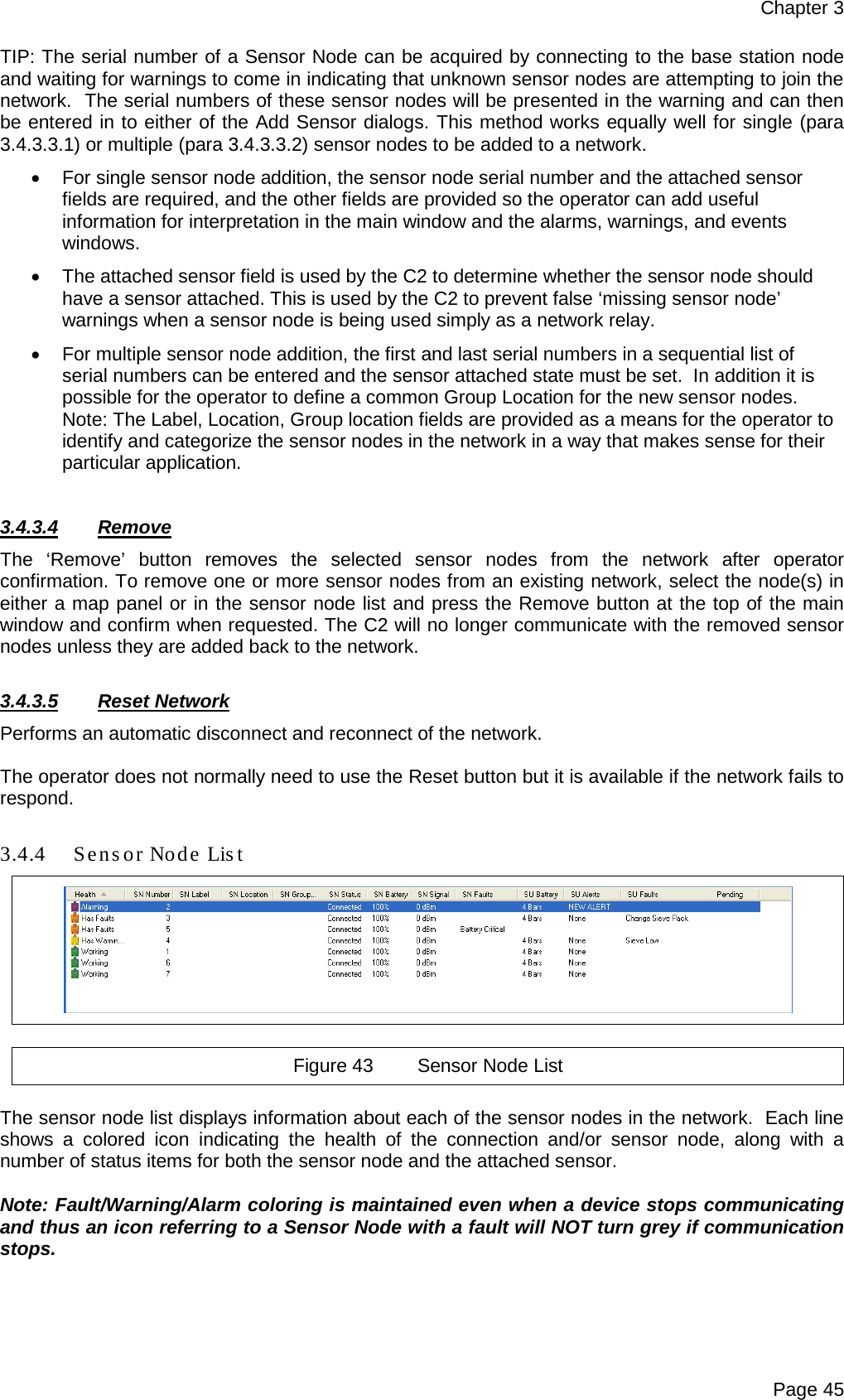
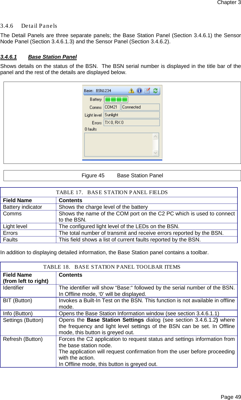
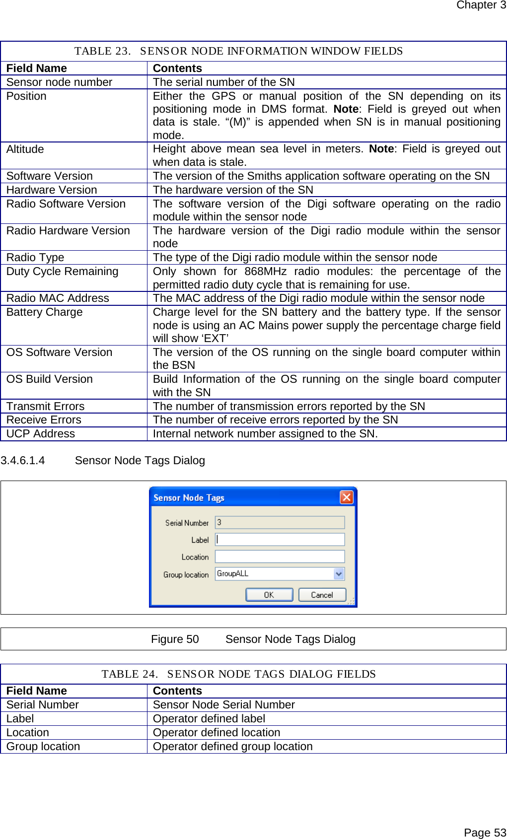
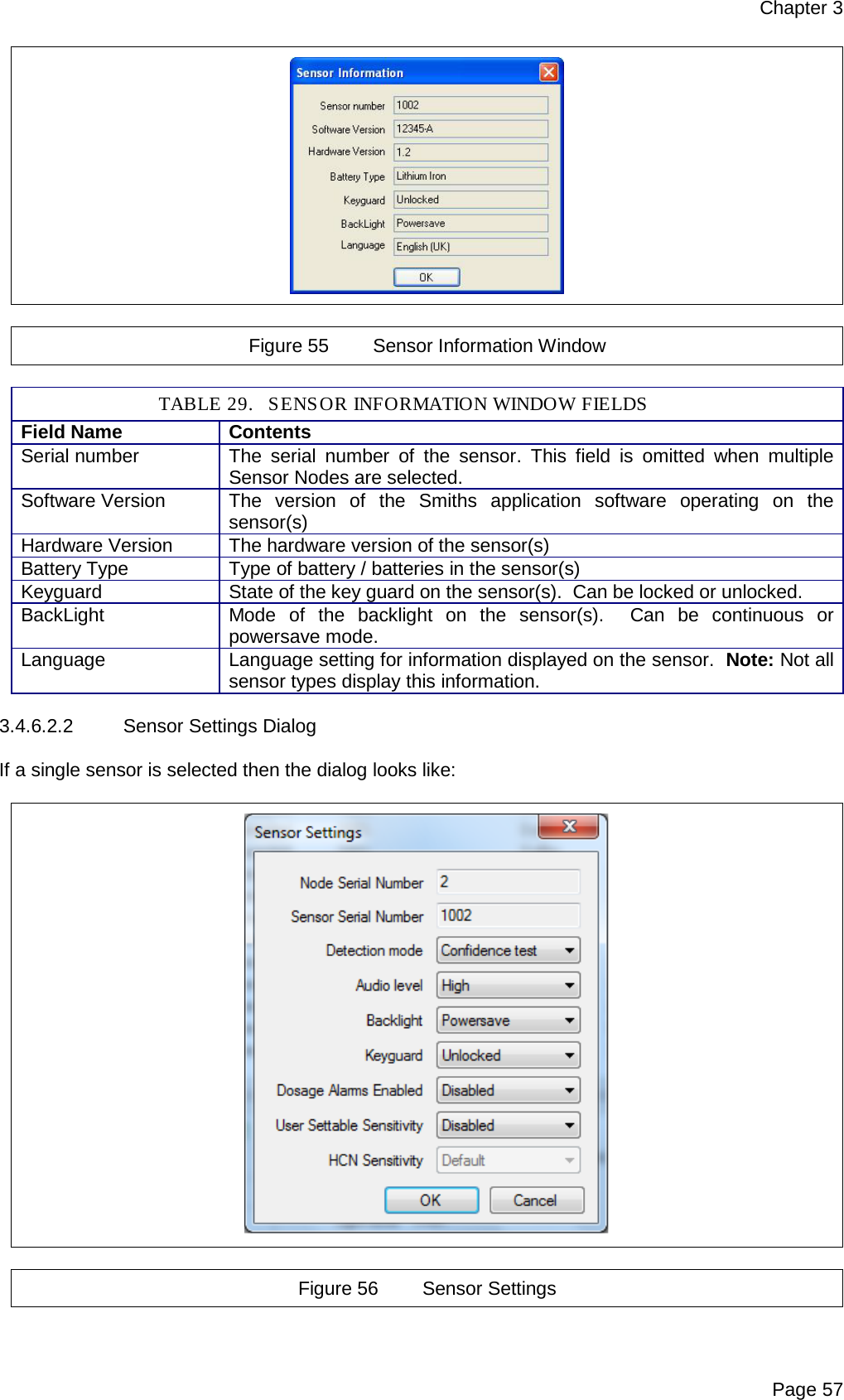
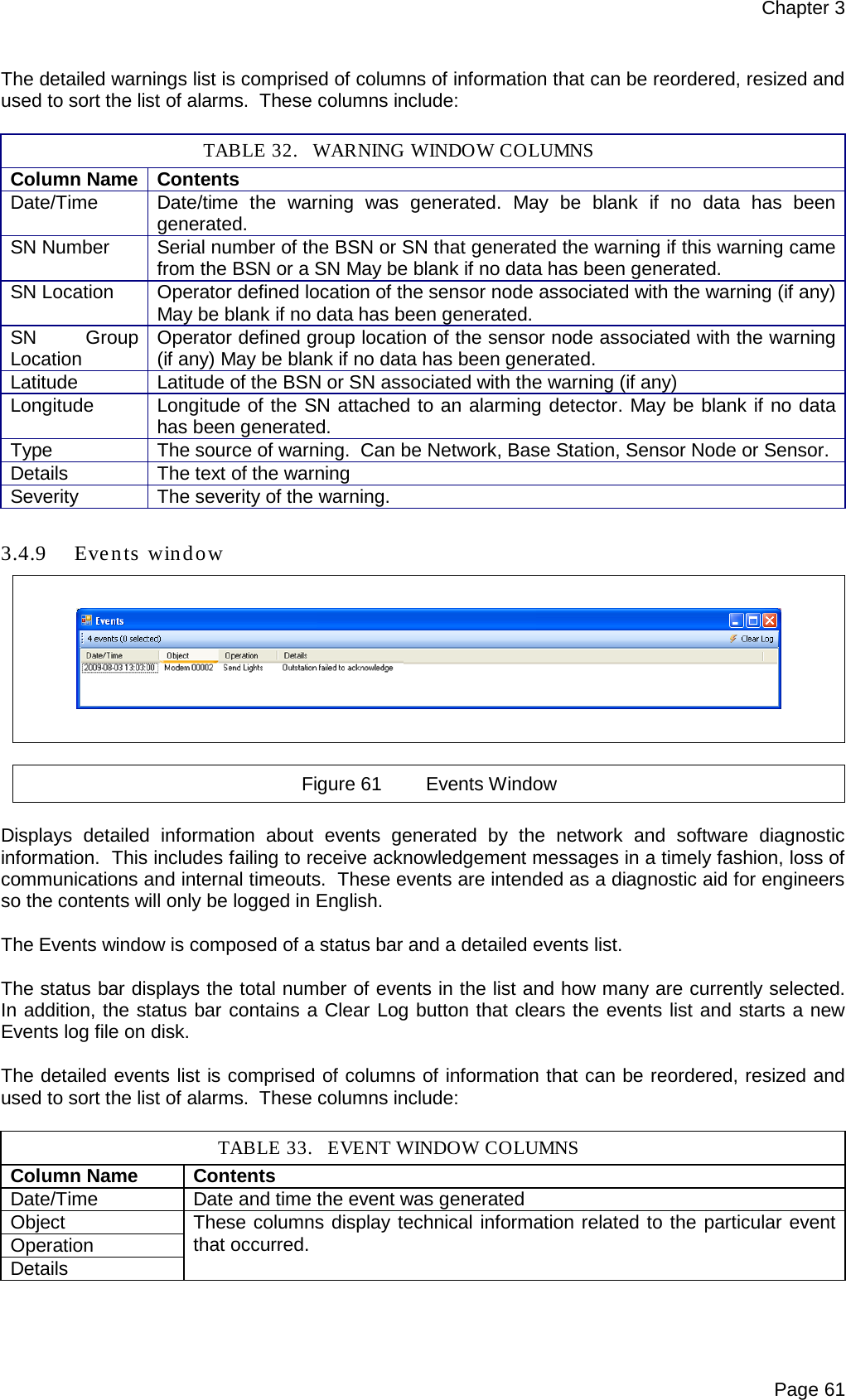
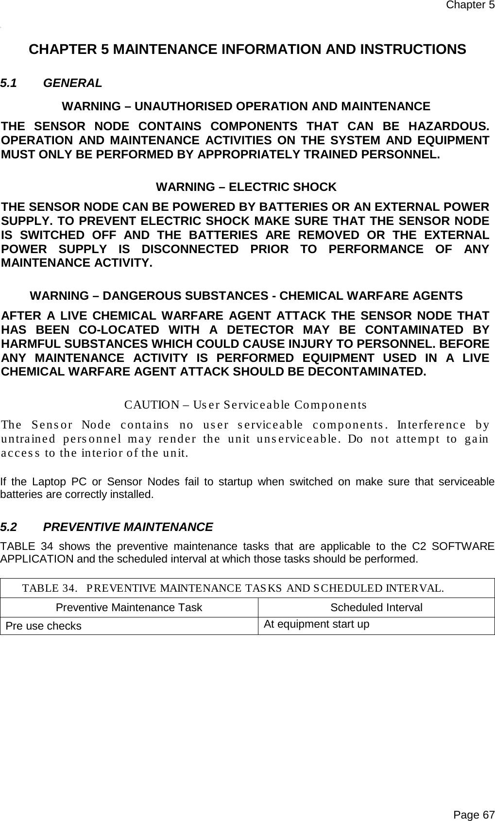
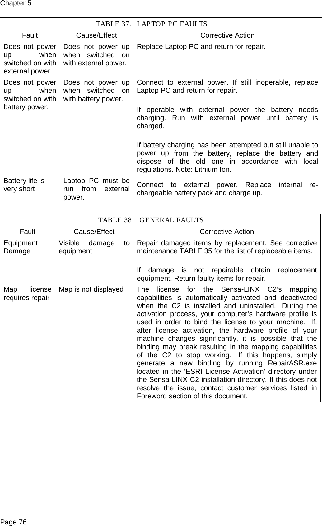
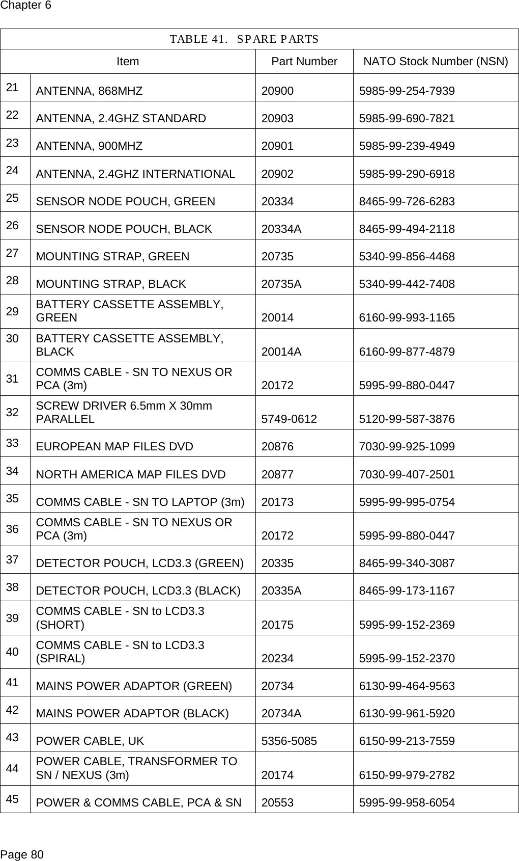
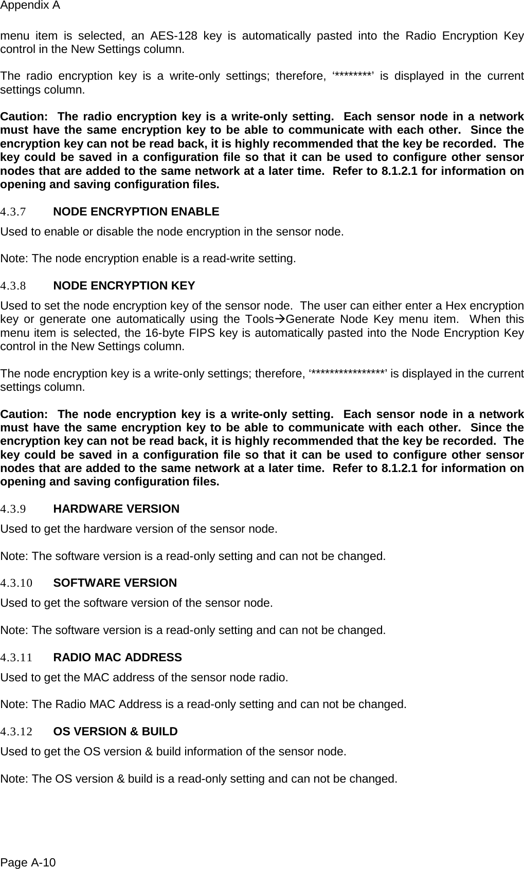
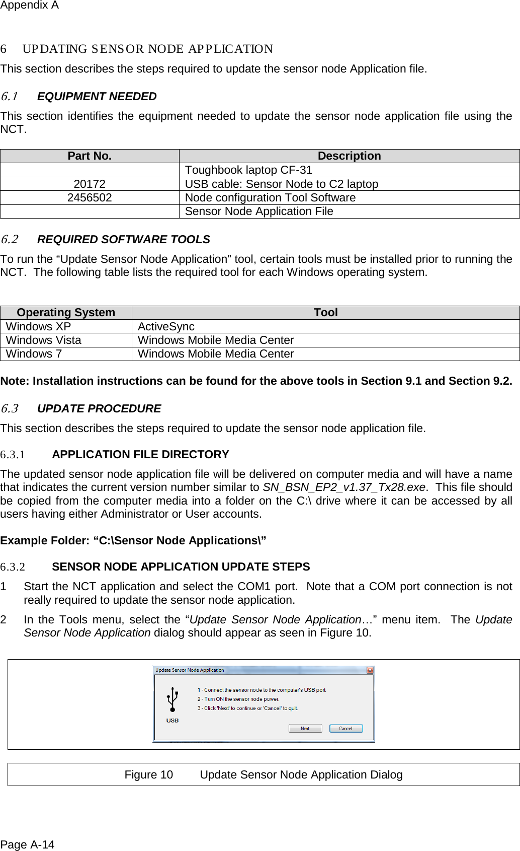
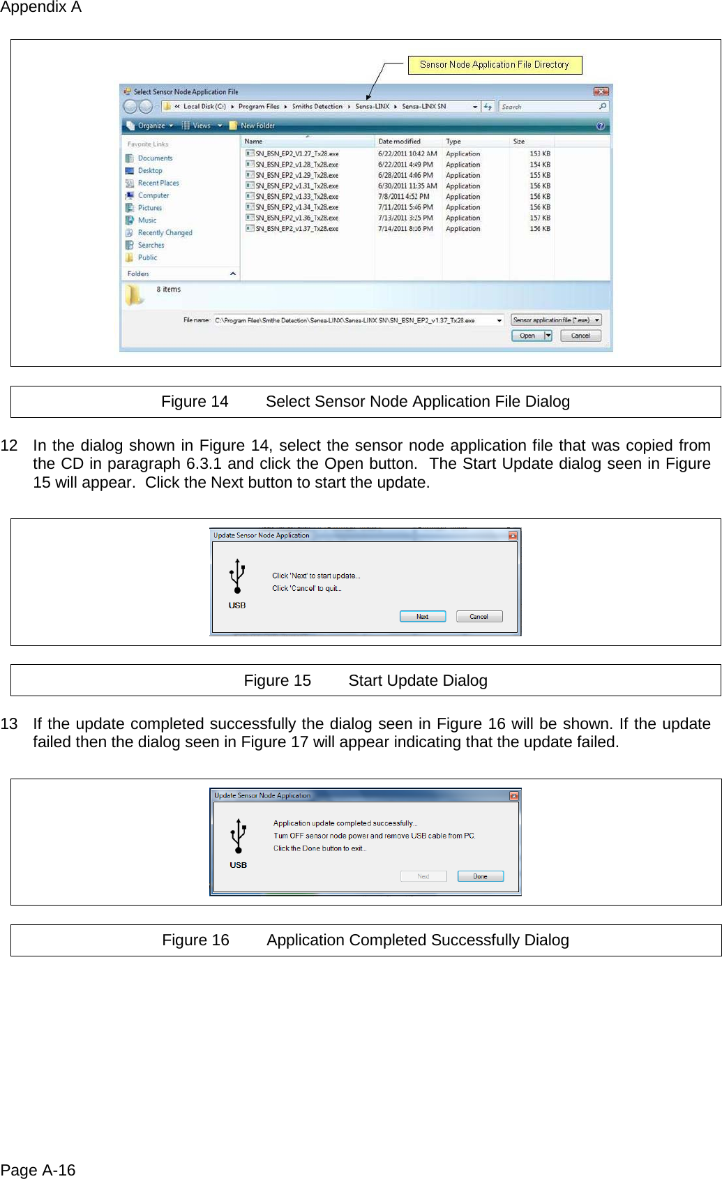
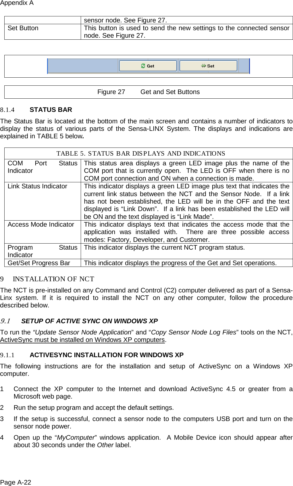
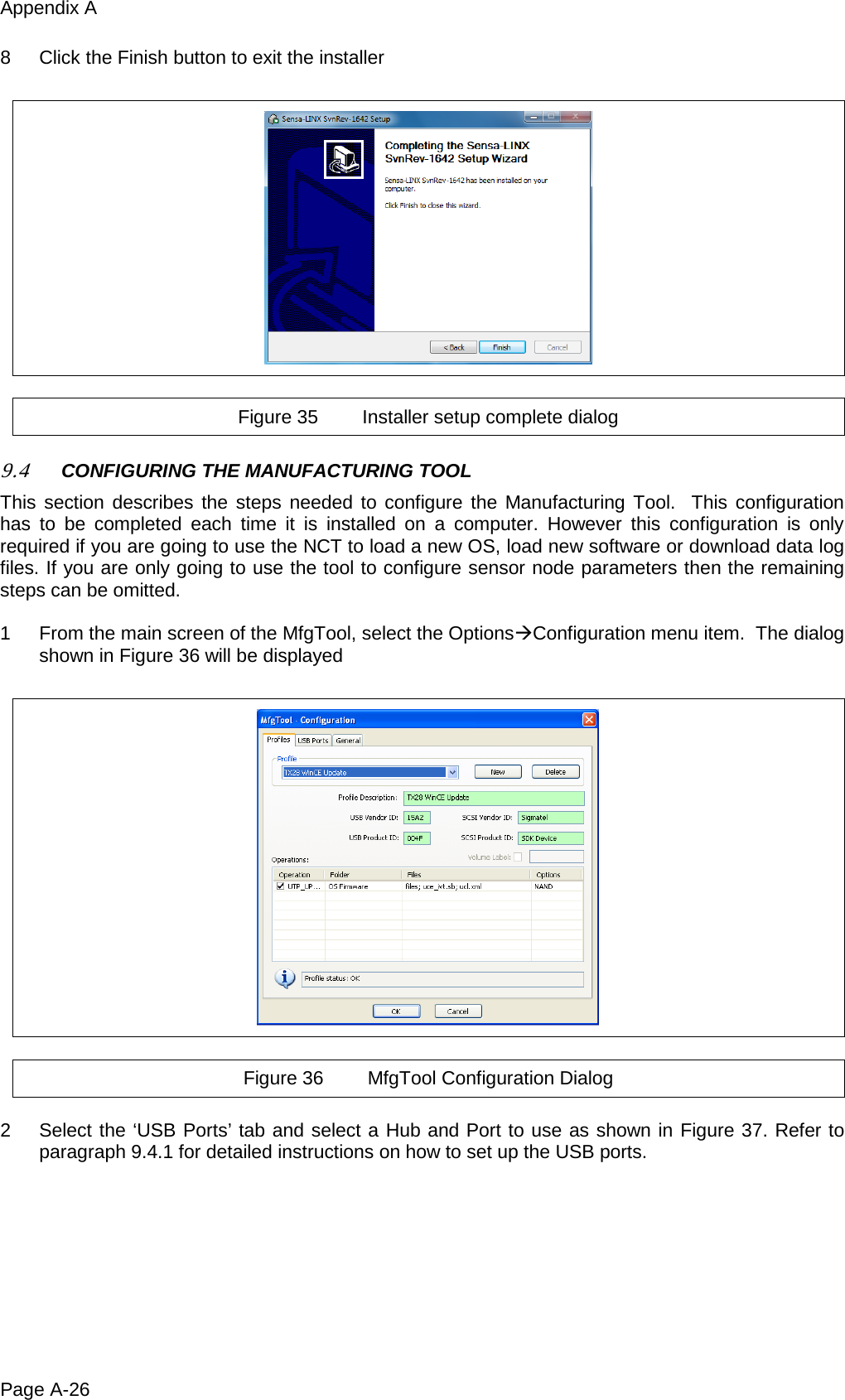
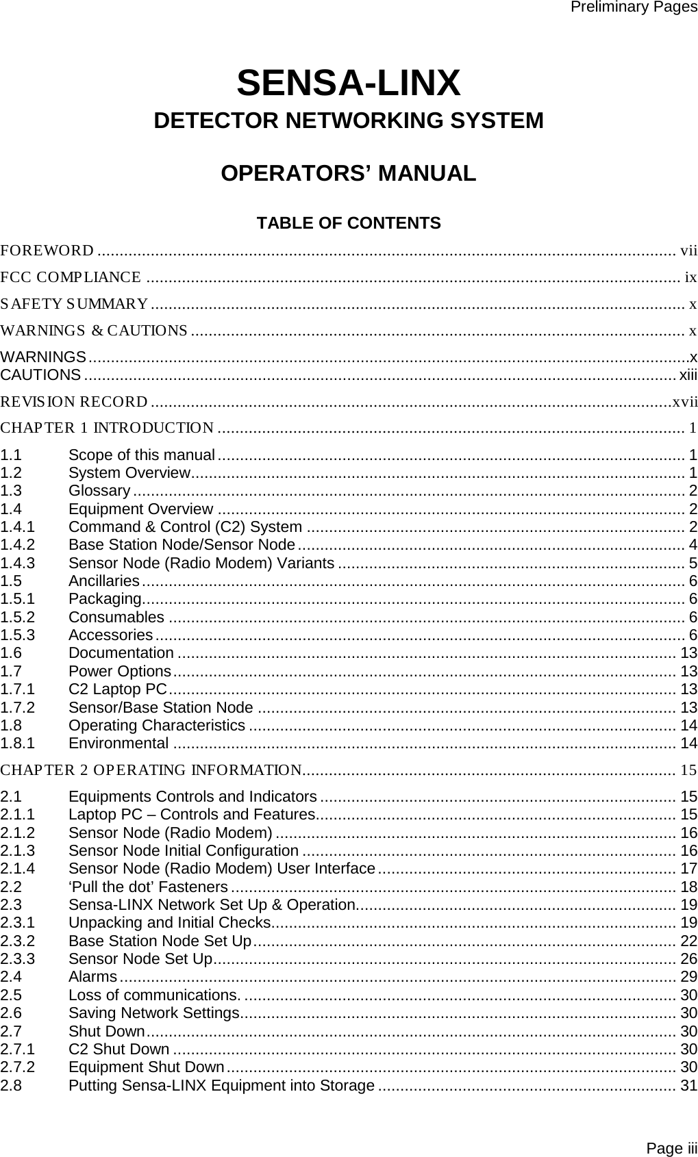
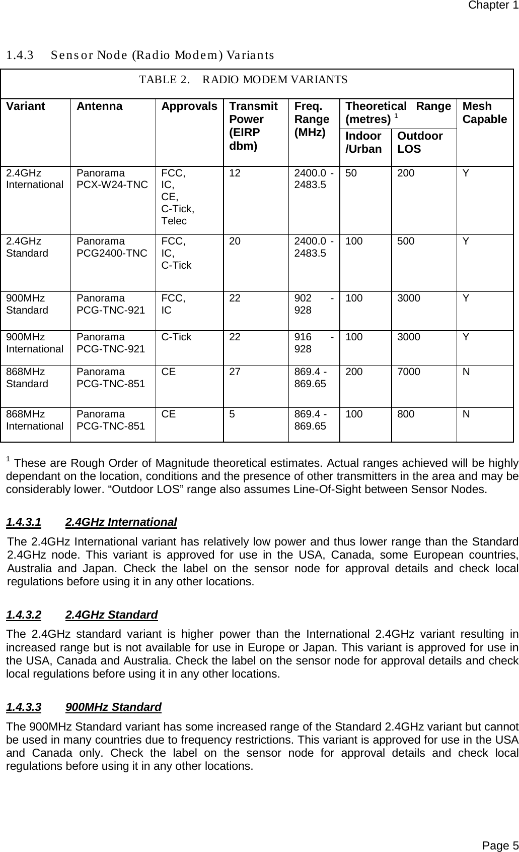
![Chapter 1 Page 12 1.5.3.9 Shoulder Strap Figure 19 Shoulder Strap (5368-9020 [Green] or 19268 [Black]) 1.5.3.10 Mounting Strap Figure 20 Mounting Strap (20735 [Green] or 20735A [Black]) Figure 21 Tripod (6881-0216)](https://usermanual.wiki/Smiths-Detection/2039924.User-Manual/User-Guide-1664813-Page-32.png)