Smiths Detection 2039924 Sensa-LINX, Wireless Early Warning System, 2.4 GHz Variant User Manual Quick Reference Guide
Smiths Detection (Watford) Sensa-LINX, Wireless Early Warning System, 2.4 GHz Variant Quick Reference Guide
Contents
- 1. User Manual
- 2. Quick Reference Guide
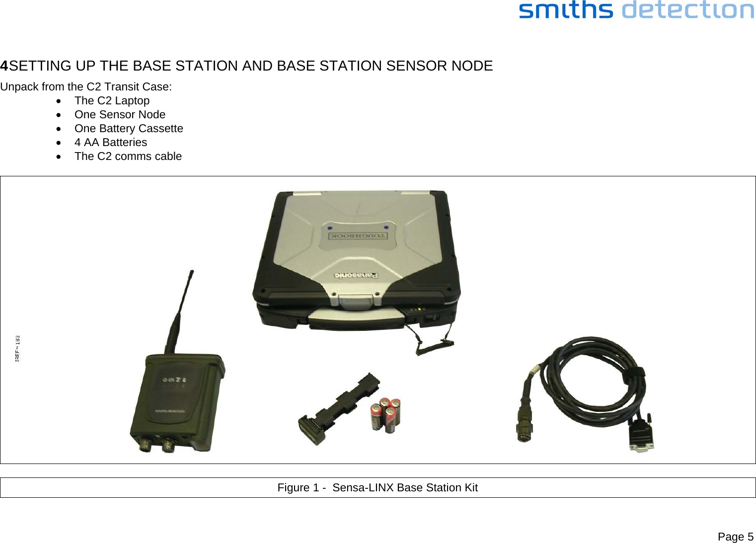
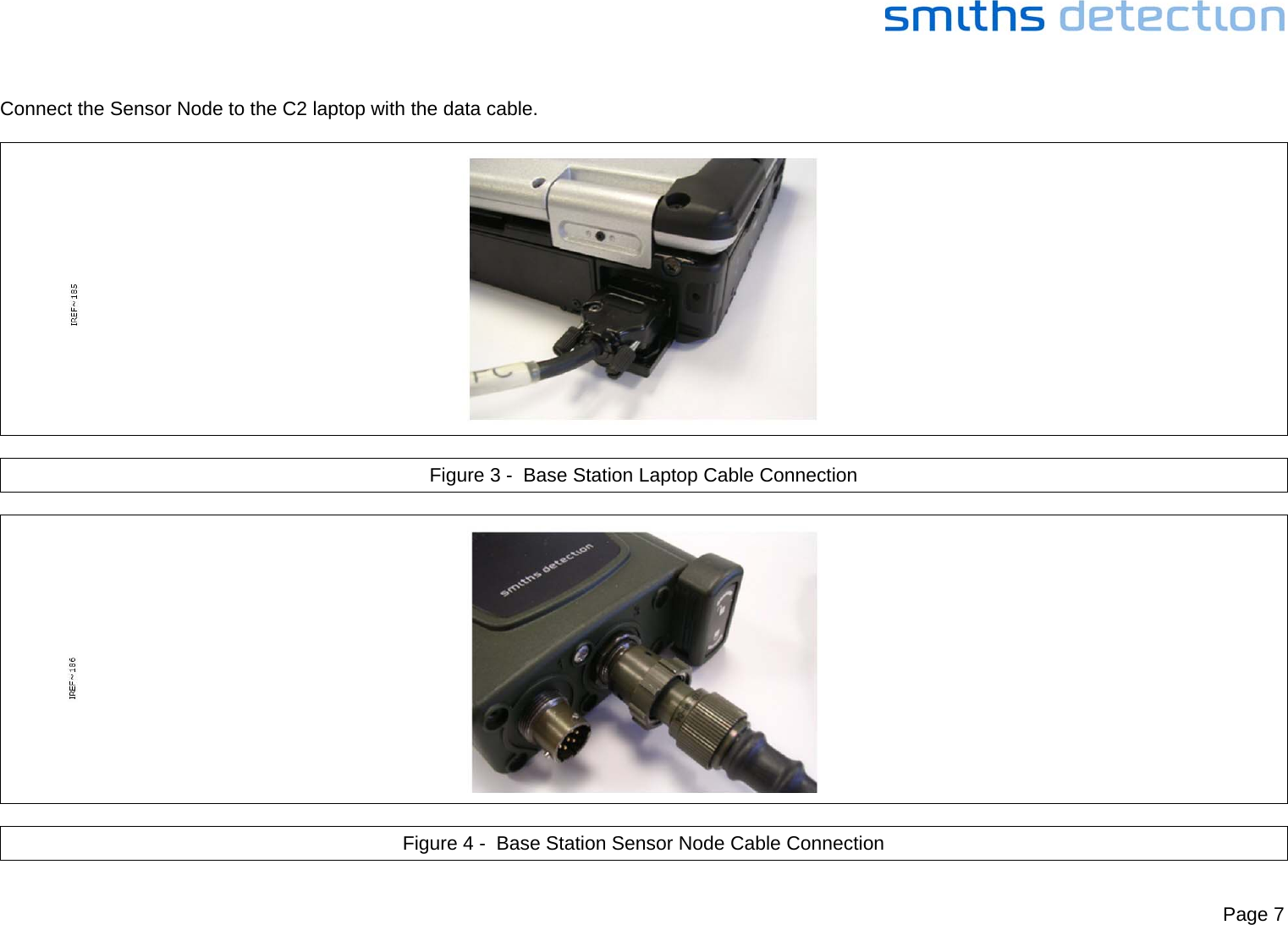
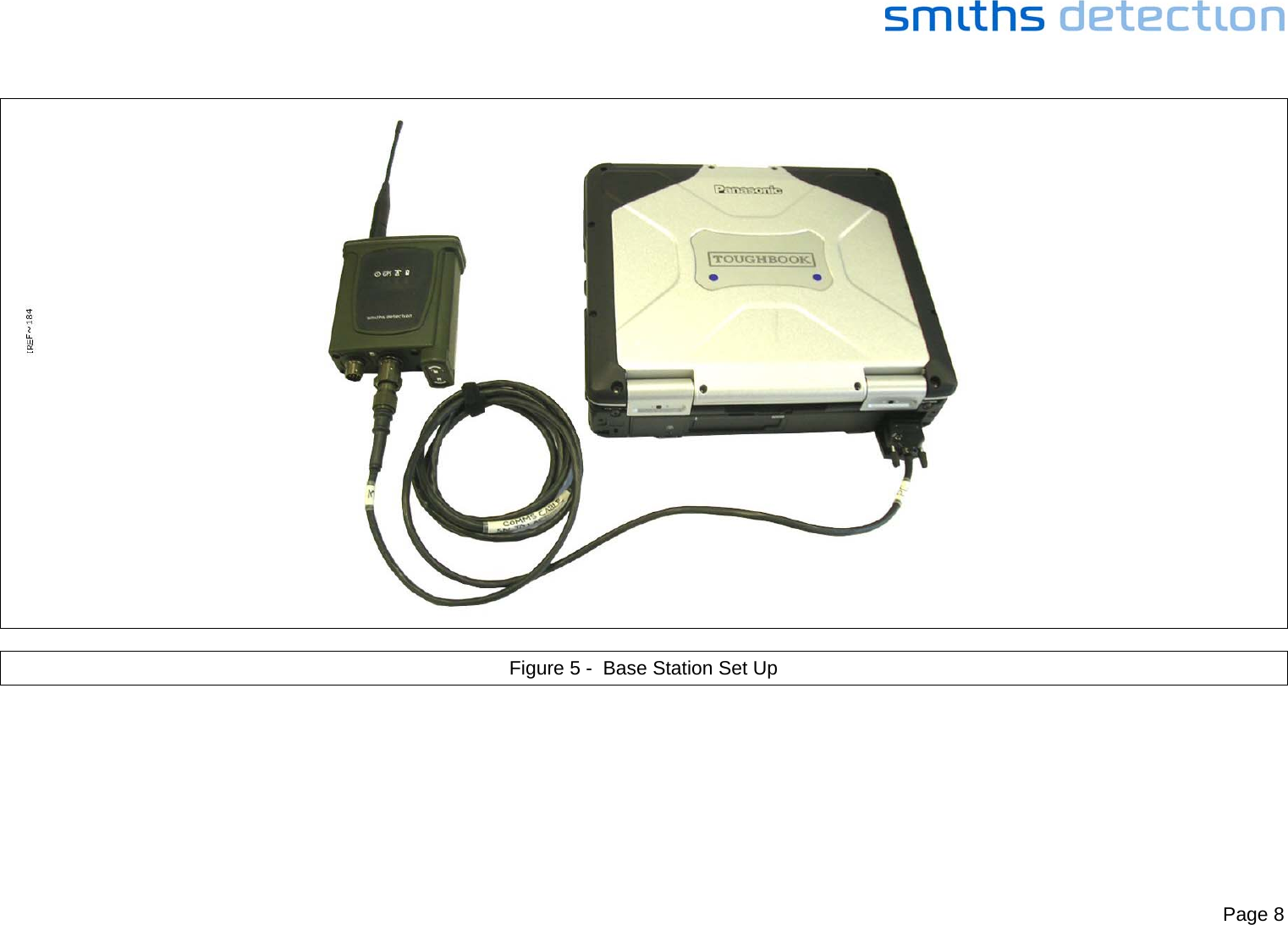
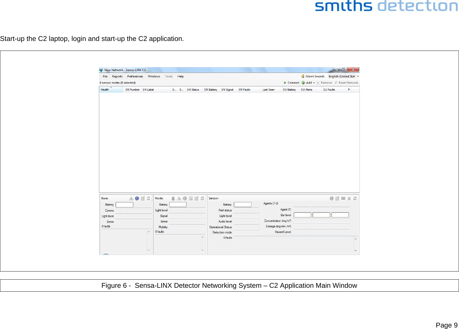
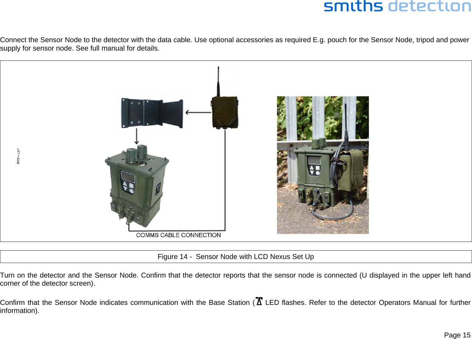
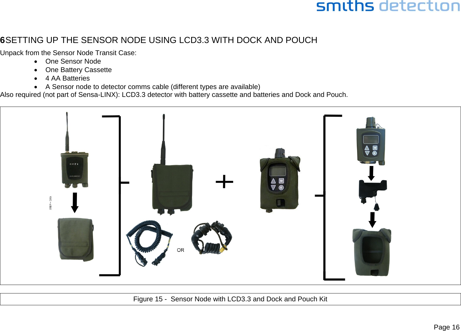
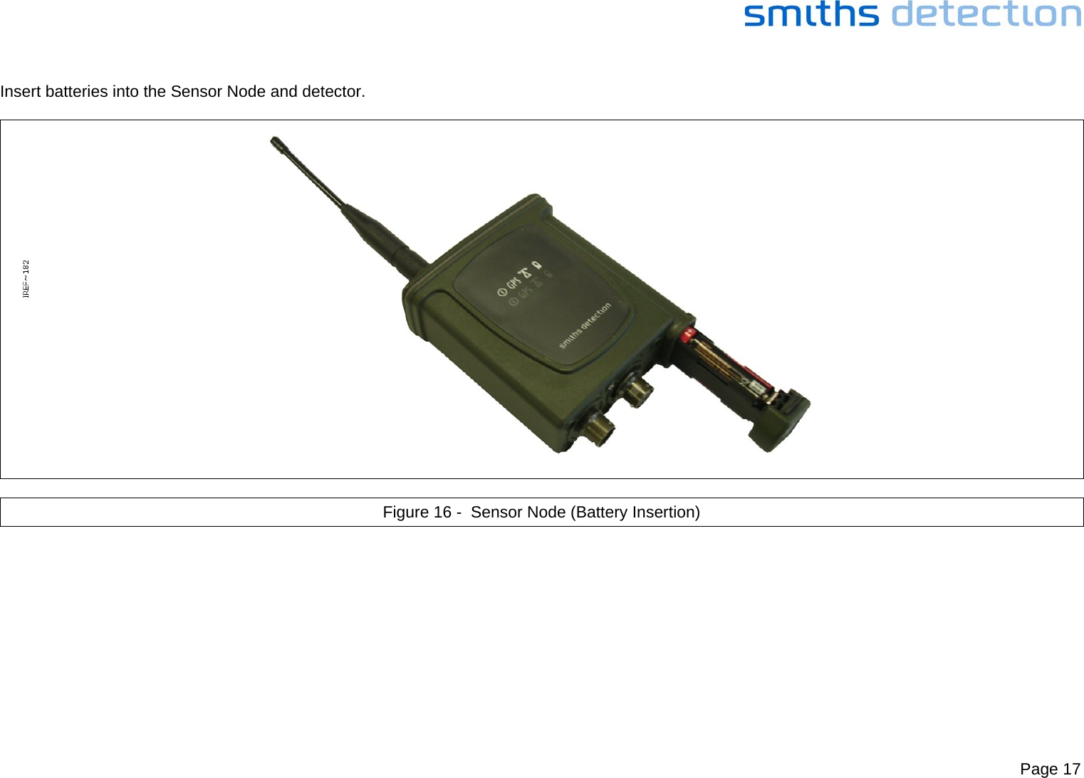
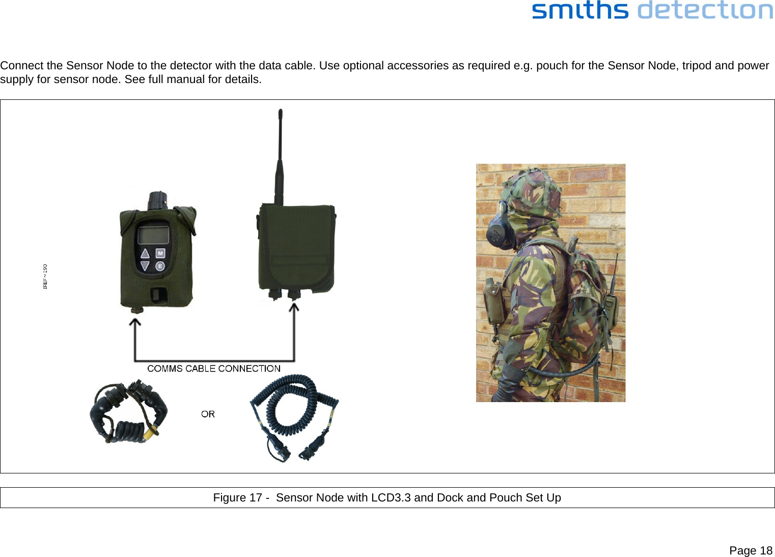
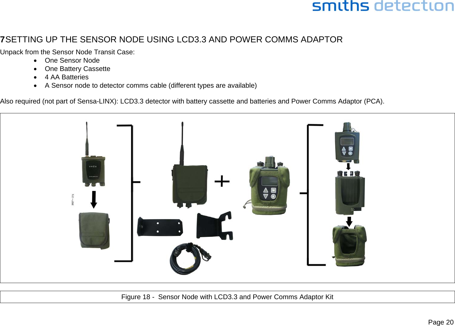
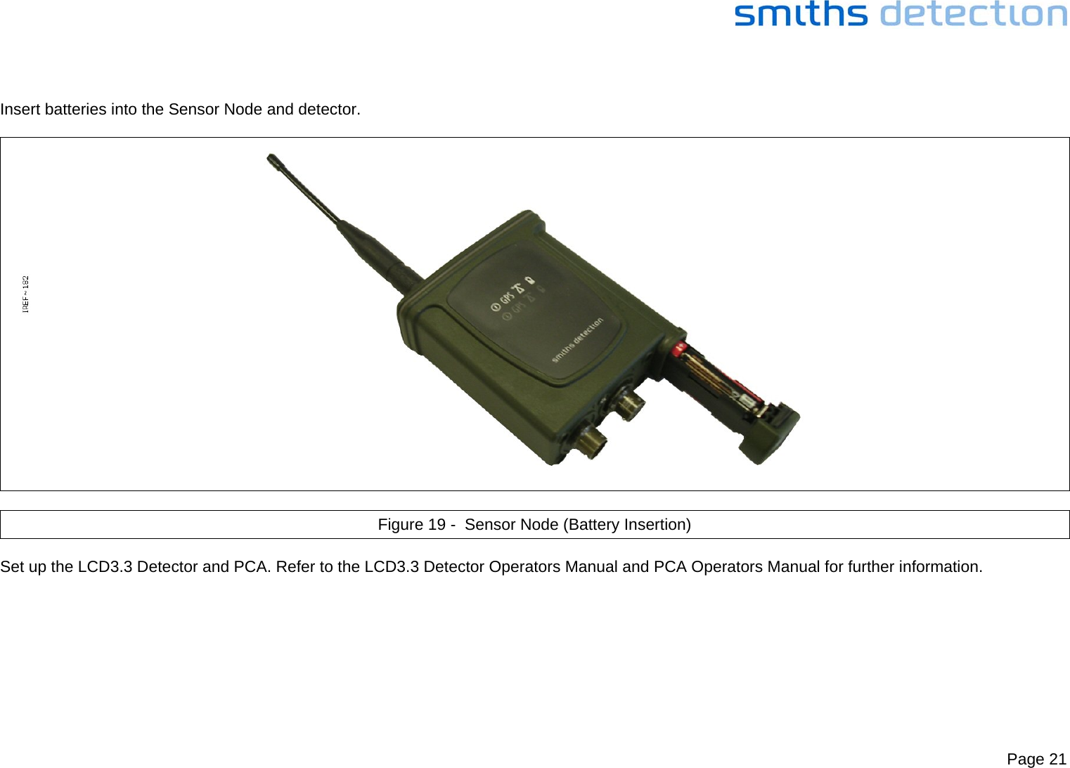
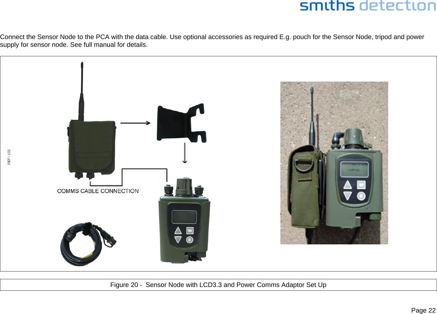
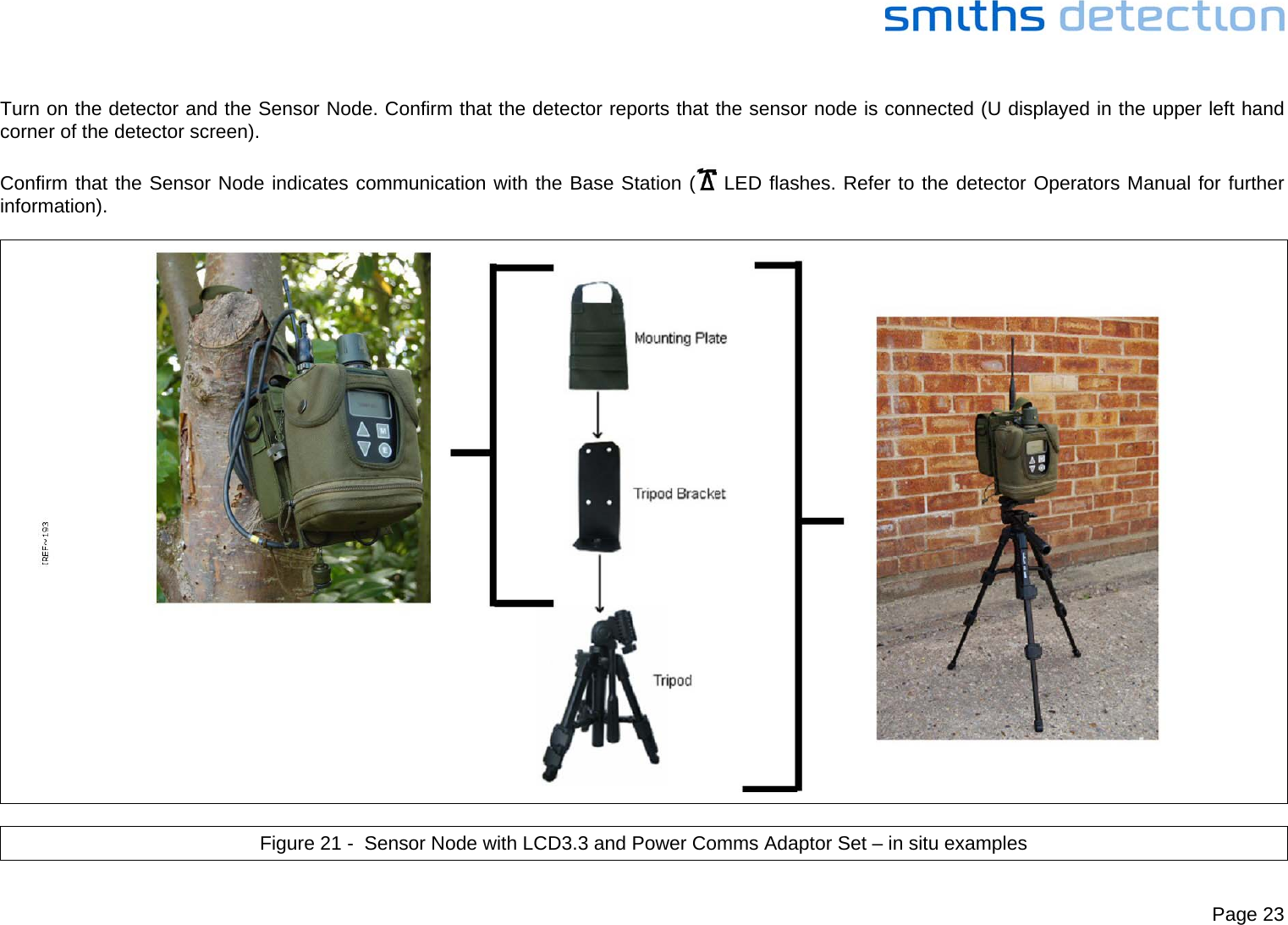
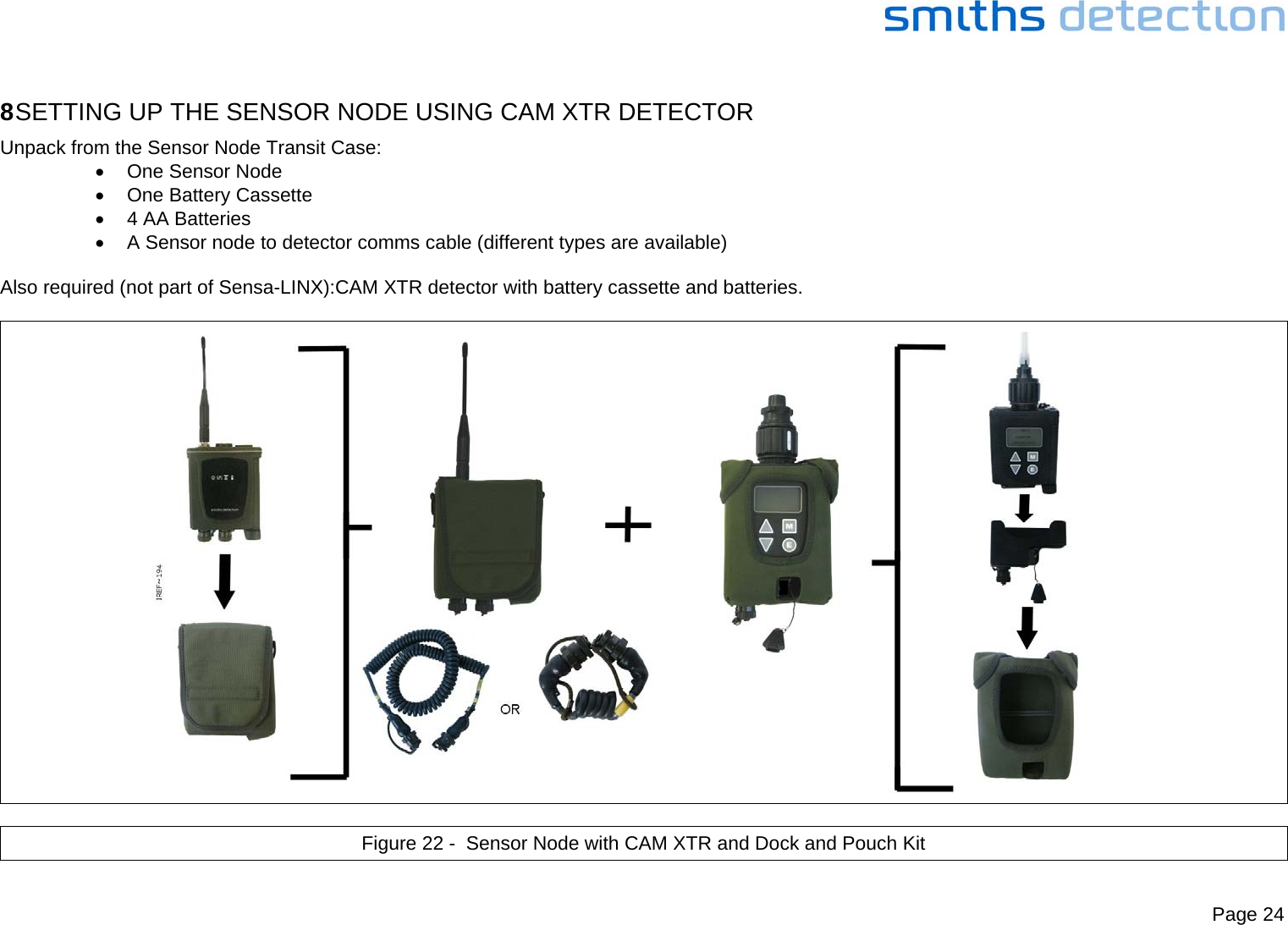
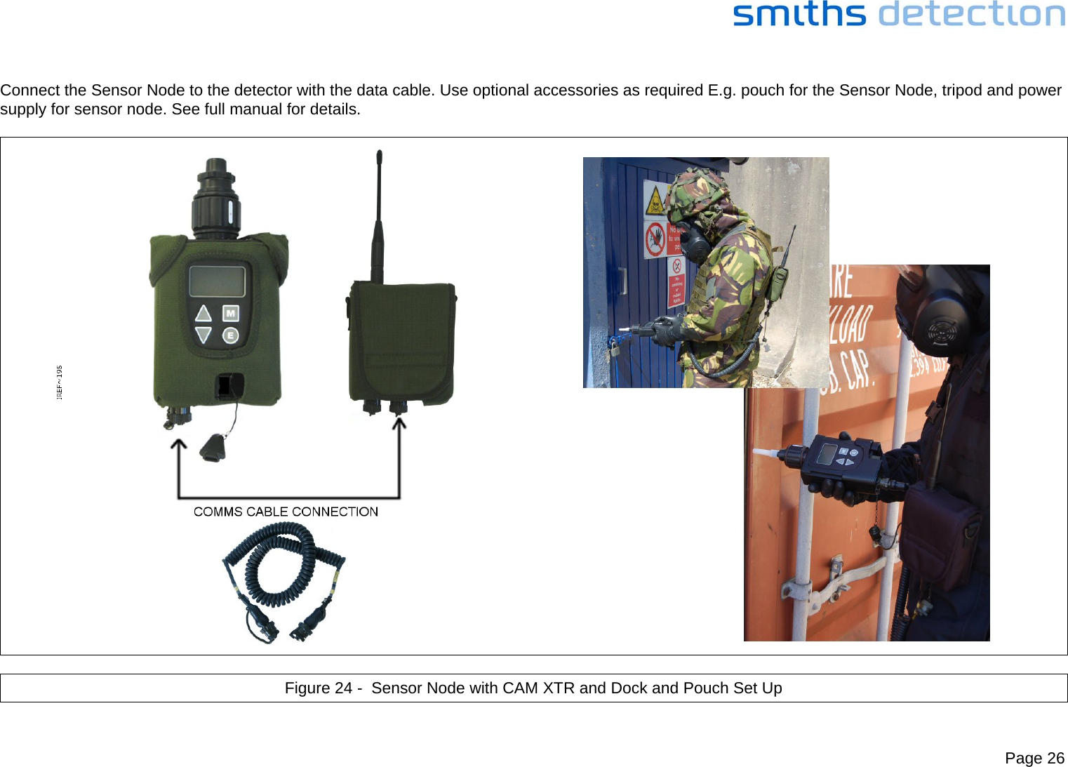
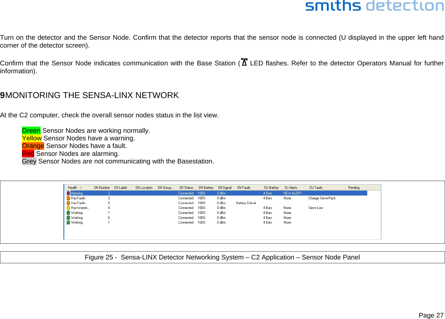
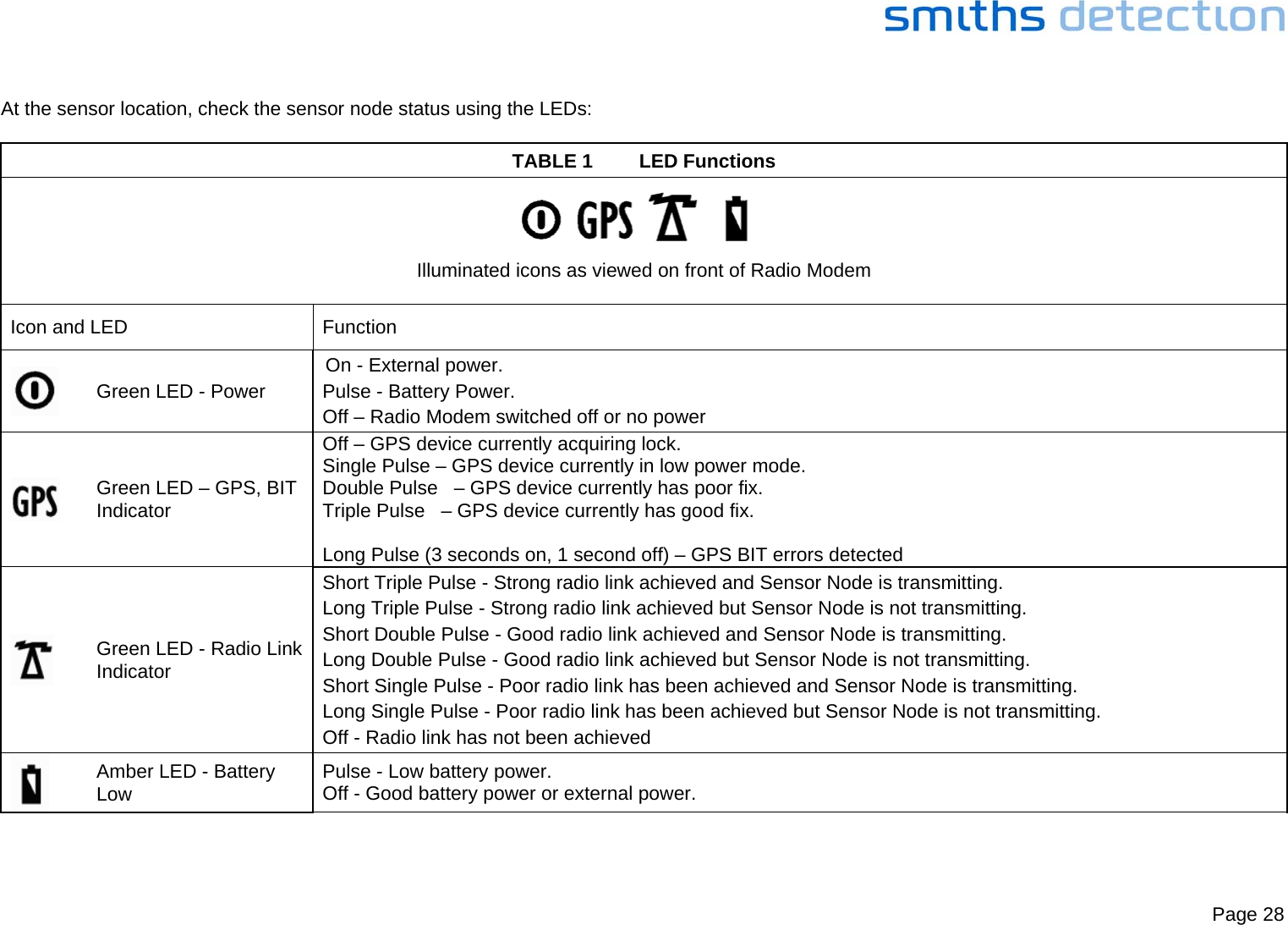
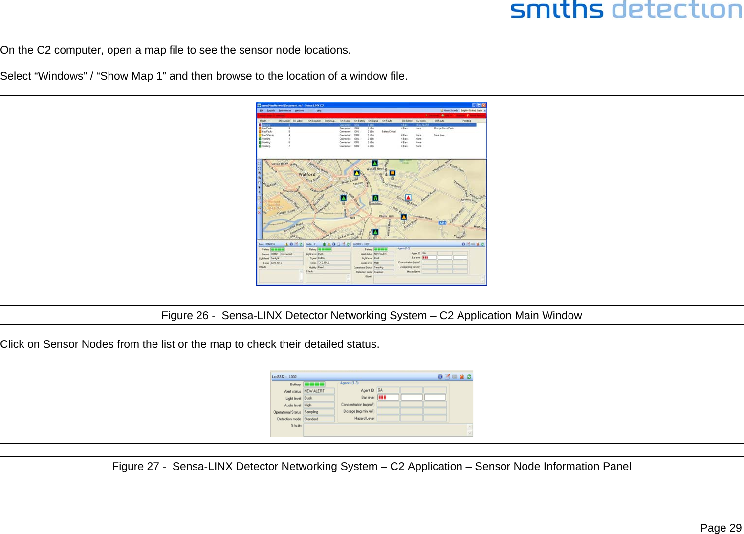
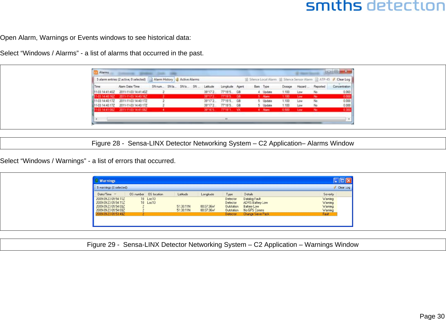
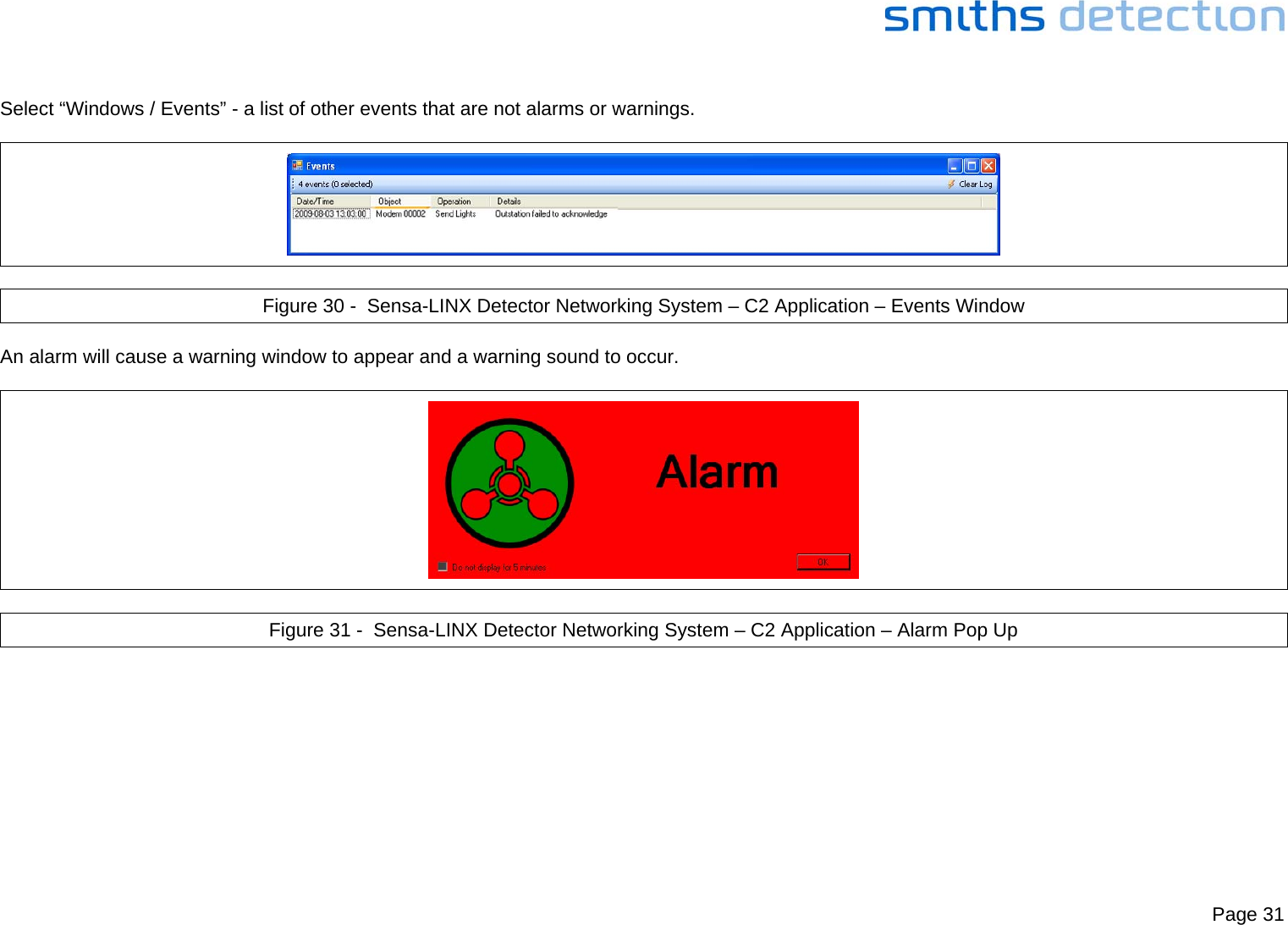
Quick Reference Guide