Smiths Detection 2039924 Sensa-LINX, Wireless Early Warning System, 2.4 GHz Variant User Manual Quick Reference Guide
Smiths Detection (Watford) Sensa-LINX, Wireless Early Warning System, 2.4 GHz Variant Quick Reference Guide
Contents
- 1. User Manual
- 2. Quick Reference Guide
Quick Reference Guide

Sensa-LINX
DETECTOR NETWORKING SYSTEM
QUICK REFERENCE GUIDE
Prepared by: Smiths Detection Ltd.
Park Avenue
Bushey
Watford
Hertfordshire
WD23 2BW
U.K.
Part No. 20449-1
Date of Issue: December 2011
Smiths
Detection
Smiths
Detection
Smiths
Detection
Smiths
Detection
Smiths
Detection
Smiths
Detection
Smiths
Detection
Smiths
Detection
Smiths
Detection
Smiths
Detection
Smiths
Detection
Smiths
Detection
Smiths
Detection
Smiths
Detection
Smiths
Detection
Smiths
Detection
Smiths
Detection

Page 2
© Smiths Detection Limited
These commodities/technical data are controlled for export by the U.S. State Department. They may not be transferred, trans-shipped, on a non-
continuous voyage, or otherwise disposed of outside of the United States, either in their original form or after being incorporated into other end- items
without the prior written approval of the U.S. Department of State.
All rights reserved. No part of this publication may be reproduced or utilised in any form or by any means, electronically or mechanically, including
photocopying and microfilm, without permission in writing from Smiths Detection Limited.
It shall be the responsibility of the purchaser solely to establish the suitability of the product for particular applications. It is also the purchaser's
responsibility to use and maintain the product in accordance with the advised procedures and recommendations.
Ownership of this equipment is constrained by End User Licence Agreements (EULA) and the technology used in the equipment may be subject to
further military and/or commercial restrictions regarding Intellectual Property Rights (IPR) and the use or transfer of information. It is the responsibility
of the user to ensure that the rights of Smiths Detection are protected at all times.
Smiths Detection Limited have made every effort to ensure the accuracy of this document but in accordance with our policy of continuous
improvement we reserve the right to make changes, without prior notice, to the equipment which is described. Smiths Detection Limited accepts no
liability for any consequential loss, injury or damage resulting from the use/misuse of the supplied information or from any errors or omissions to this
manual.
For further information or any other queries regarding equipment maintenance, servicing etc. contact:
Customer Services
Smiths Detection Limited
459 Park Avenue
Bushey, Watford
Hertfordshire
England, WD23 2BW
Tel: +44 (0) 1923 658170
Fax: +44 (0) 1923 658010
e-mail: global.support@smithsdetection.com

Page 3
1 SCOPE OF THIS MANUAL
This Quick Reference Guide provides basic information about complete equipment schedules and set up details for the Sensa-LINX Detector and
details to contact the equipment manufacturer.
2 IMPORTANT INFORMATION
2.1 WINDOWS DISKS
The Toughbook computer you have been supplied with does not have an accompanying Windows disk from which to restore it in the event of disk
failure (though it does have a recovery partition on the hard disk from which the operating system can be recovered in the event of some disk errors
or corruption). It is strongly recommended that you use the Panasonic Recovery Disc Creation Utility to create Recovery disks for your Toughbook.
You will need two blank DVDs for this purpose. NOTE that you will only be able to create one set of recovery disks. You should therefore take care
not to lose these recovery disks once you have created them.
2.2 USER ACCOUNTS AND PASSWORDS
Your Toughbook computer has been supplied with 2 Windows user accounts – Administrator and User. Both these accounts have been configured to
have blank passwords. It is strongly recommended that you should manage user accounts and passwords in accordance with your organization’s
operating procedures.
2.3 ANTI-VIRUS
Your Toughbook computer has been supplied without any Anti-Virus software. It is recommended that you install anti-virus and security software in
accordance with your organization’s operating procedures.

Page 4
3 EQUIPMENT OVERVIEW
The Sensa-LINX Detector Networking System has been designed to allow a number of LCD 3.3 detectors (with or without Power/Comms Adaptors
(PCA) or Adaptor Pouches) and LCD-NEXUS detectors to be combined as a network, wirelessly connected to a single location to provide centralized
recording of data, and control and monitoring of the detectors. Each detector is connected to a specialized radio modem. This set up is termed a
Sensor Node which communicates with a radio modem connected to the Controller Laptop at the central monitoring location. This central monitoring
location is termed the Base Station Node. The Controller Laptop has the Command & Control (C2) program installed that records, interprets and
displays the data supplied by the detectors via the Sensor Node radio modems. The data acquired from the network of detectors can then be used to
produce Chemical, Biological, Radiological Nuclear and Explosives (CBRNE) reports.
It is important to note that the data transmissions from the Sensor Nodes can be intercepted, however these transmissions are encrypted
using the Sensa-LINX system and cannot read by other agencies.
The radio modems have built-in Global Positioning System (GPS) receivers to obtain position co-ordinates from GPS satellites and display their
position on a GIS map. Functioning GPS is not vital to the operation of the Sensa-LINX system. The GPS receiver is activated at startup but may be
disabled to conserve battery power if the Sensor Node is used on a Fixed Installation. If the Sensor Node is used in a mobile situation the GPS signal
will update the Sensor Node’s position when movement is detected.
Depending on the type of radio modem used the network may be either a mesh network or a non-mesh network. In a mesh network the radio
modems within transmission range of the Base Station Node ‘repeat’ the signals from the radio modems of Sensor Nodes beyond the nominal
transmission range or where there are ‘line-of-sight’ problems. In non-mesh networks all of the Sensor Nodes must be within the nominal
transmission range with no ‘line-of-sight’ problems.
Page 5
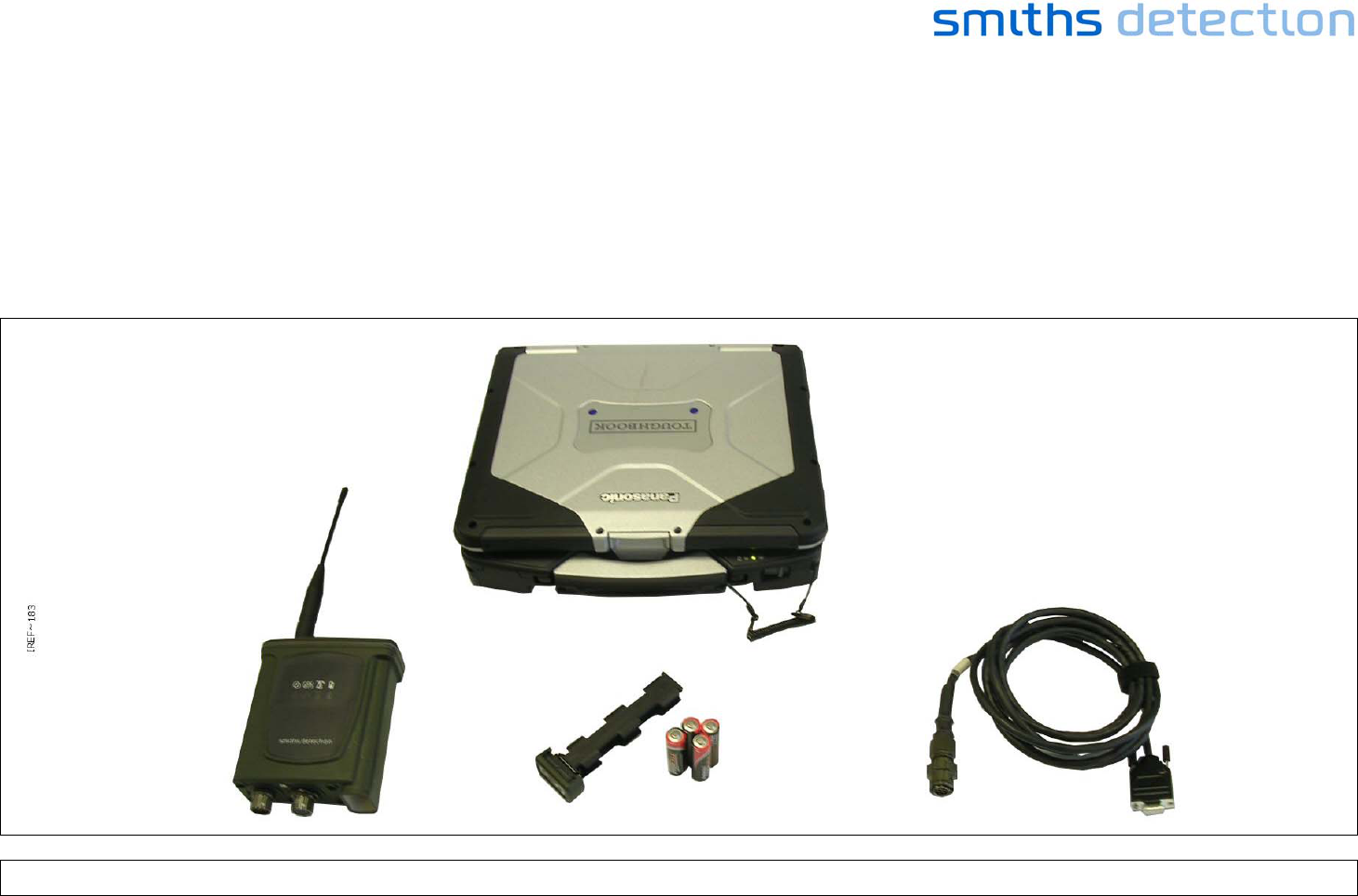
4 SETTING UP THE BASE STATION AND BASE STATION SENSOR NODE
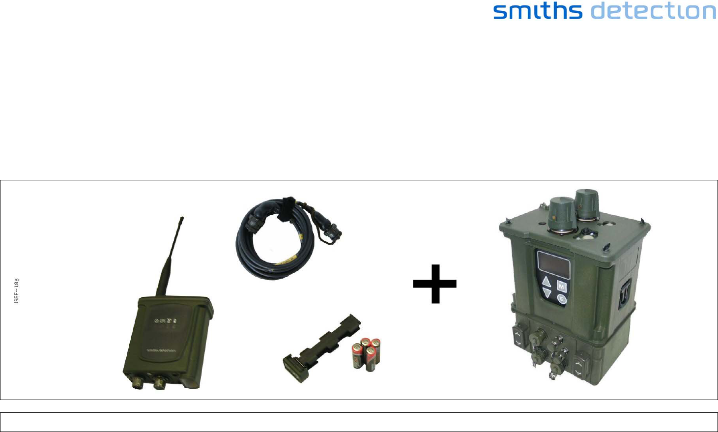
Unpack from the C2 Transit Case:
• The C2 Laptop
• One Sensor Node
• One Battery Cassette
• 4 AA Batteries
• The C2 comms cable
Figure 1 - Sensa-LINX Base Station Kit

Page 6
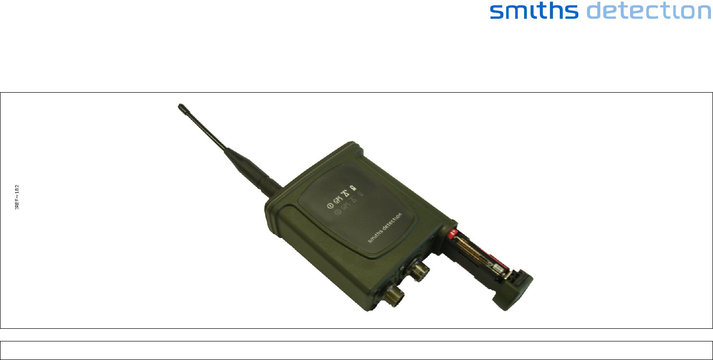
Insert batteries into the Sensor Node.
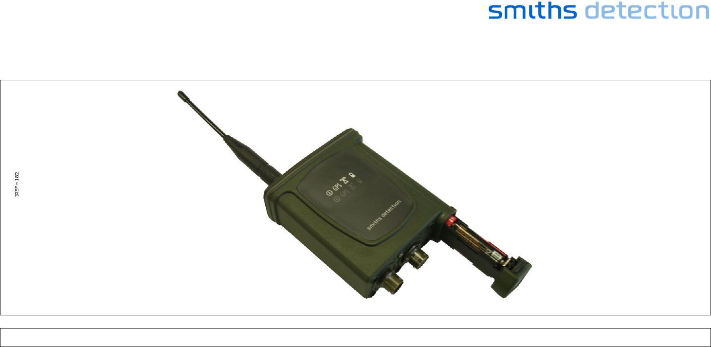
Figure 2 - Sensor Node (Battery Insertion)
Page 7
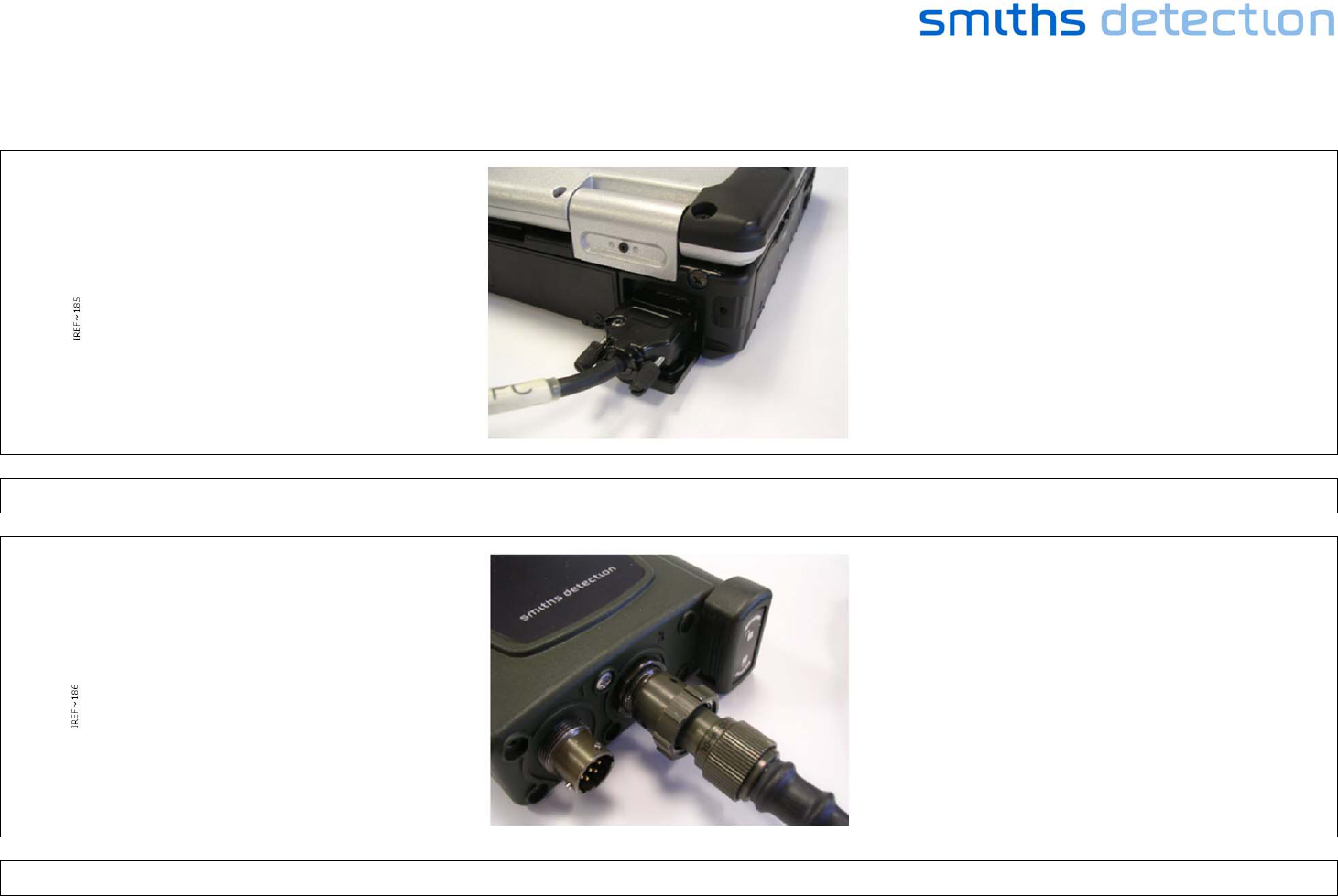
Connect the Sensor Node to the C2 laptop with the data cable.
Figure 3 - Base Station Laptop Cable Connection
Figure 4 - Base Station Sensor Node Cable Connection
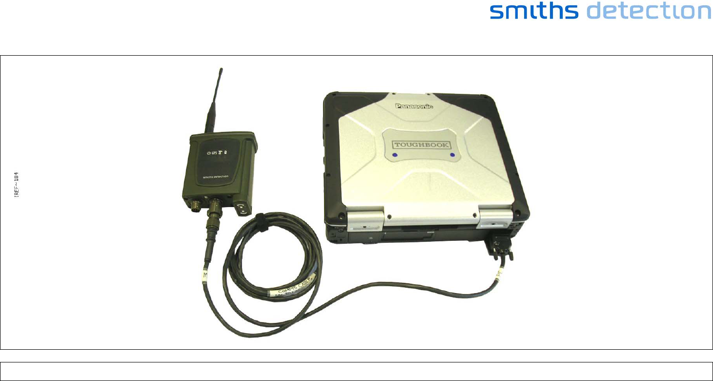
Page 8
Figure 5 - Base Station Set Up
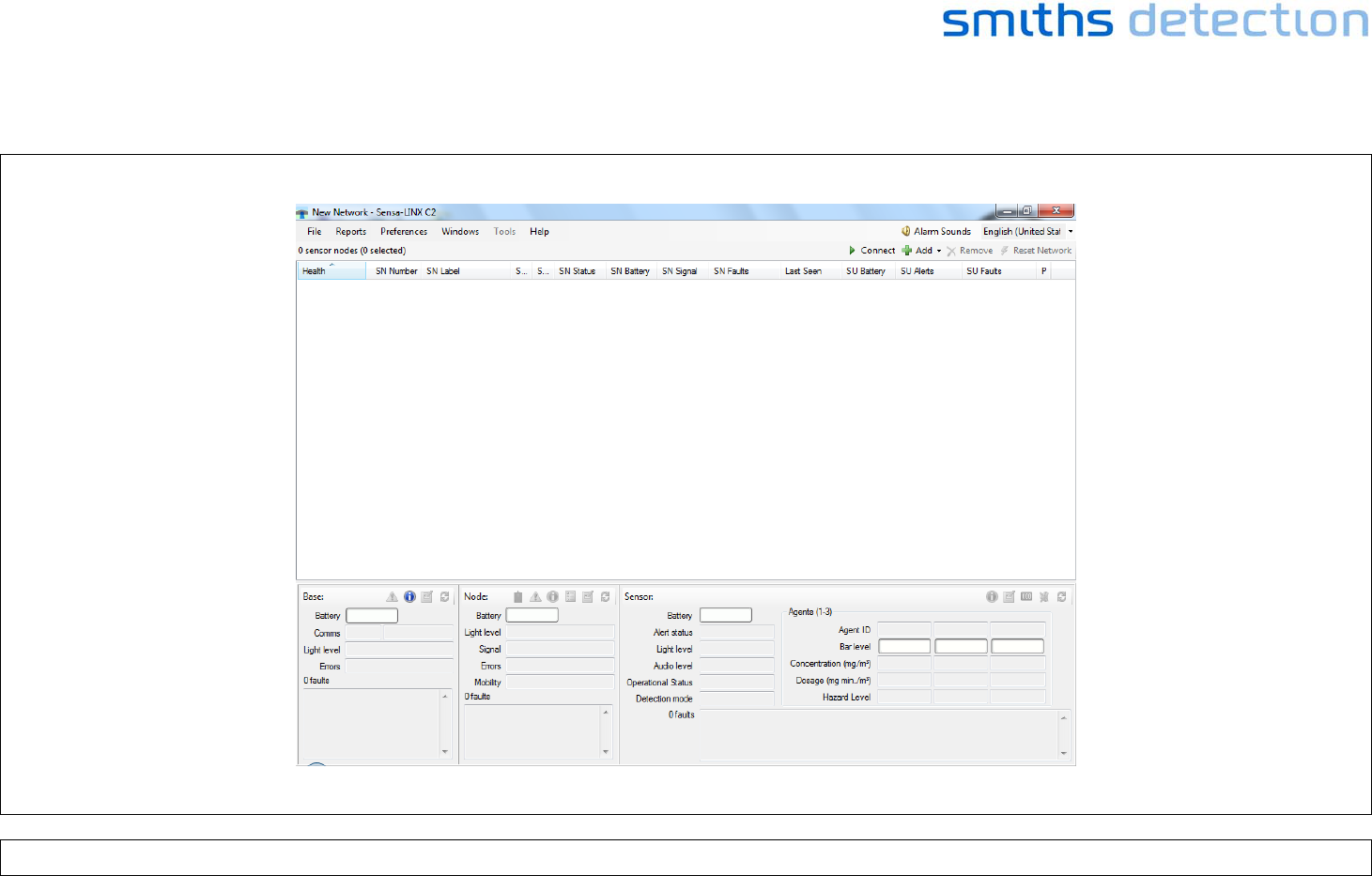
Page 9
Start-up the C2 laptop, login and start-up the C2 application.
Figure 6 - Sensa-LINX Detector Networking System – C2 Application Main Window
Page 10
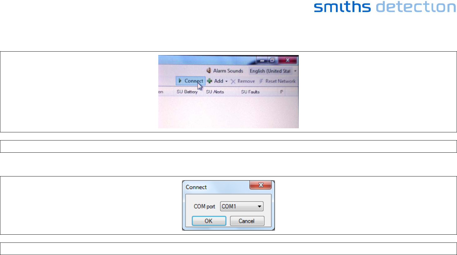
Turn on the sensor node and press the “Connect” button.
Figure 7 - Sensa-LINX Detector Networking System – C2 Application Main Window – Sensor Node ‘Connect’ Button
Select the COM port (COM1 for the provided Sensa-LINX laptop) and press OK.
Figure 8 - Sensa-LINX Detector Networking System – Connect Dialog
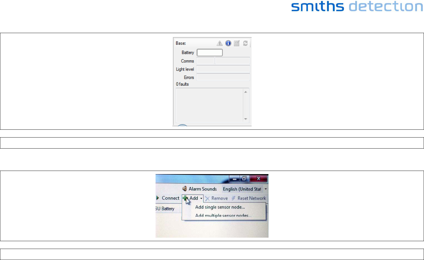
Wait for the basestation to show that it is connected to the C2.
Page 11
Figure 9 - Sensa-LINX Detector Networking System – Base Station information Window
At the C2 press the “Add” button and select either “Add Single sensor Node…” or “Add Multiple Sensor Nodes”.
Figure 10 - Sensa-LINX Detector Networking System – C2 Application Main Window – Sensor Node ‘Add’ Button
Page 12
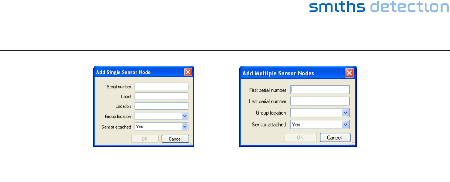
Enter the serial number(s) of the sensor nodes that you want to be on the network.
Figure 11 - Sensa-LINX Detector Networking System – Add Single and Add Multiple Sensor Node Dialogs
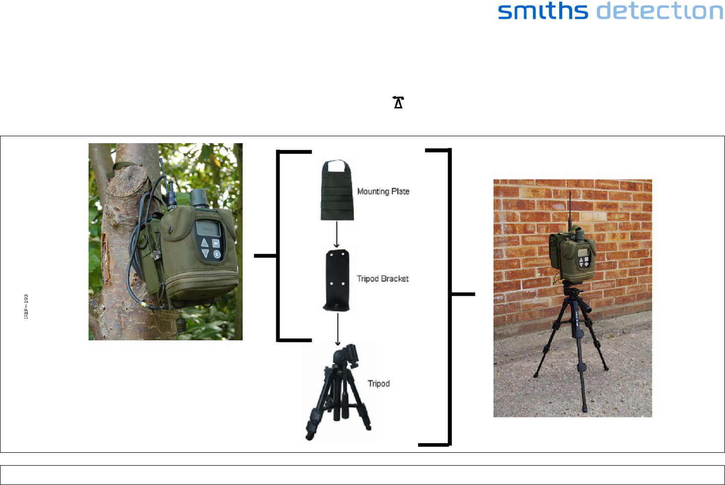
Use optional accessories as required
E.g. pouch for the Sensor Node, tripod, power supply for laptop and power supply for sensor node. See full manual for details.
Page 13
5 SETTING UP THE SENSOR NODE USING LCD NEXUS
Unpack from the Sensor Node Transit Case:
• One Sensor Node
• One Battery Cassette
• 4 AA Batteries
• A Sensor node to detector comms cable (different types are available)
Also required (not part of Sensa-LINX): LCD Nexus detector with battery cassette and batteries.
Figure 12 - Sensor Node with LCD Nexus Kit

Page 14
Insert batteries into the Sensor Node and detector.
Figure 13 - Sensor Node (Battery Insertion)
Page 15
Connect the Sensor Node to the detector with the data cable. Use optional accessories as required E.g. pouch for the Sensor Node, tripod and power
supply for sensor node. See full manual for details.
Figure 14 - Sensor Node with LCD Nexus Set Up
Turn on the detector and the Sensor Node. Confirm that the detector reports that the sensor node is connected (U displayed in the upper left hand
corner of the detector screen).
Confirm that the Sensor Node indicates communication with the Base Station ( LED flashes. Refer to the detector Operators Manual for further
information).
Page 16
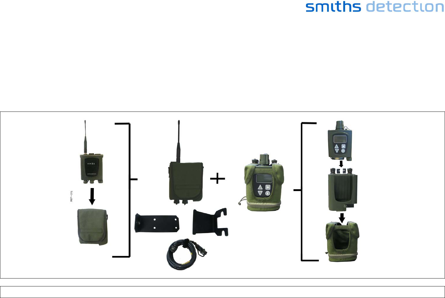
6 SETTING UP THE SENSOR NODE USING LCD3.3 WITH DOCK AND POUCH
Unpack from the Sensor Node Transit Case:
• One Sensor Node
• One Battery Cassette
• 4 AA Batteries
• A Sensor node to detector comms cable (different types are available)
Also required (not part of Sensa-LINX): LCD3.3 detector with battery cassette and batteries and Dock and Pouch.
Figure 15 - Sensor Node with LCD3.3 and Dock and Pouch Kit

Page 17
Insert batteries into the Sensor Node and detector.
Figure 16 - Sensor Node (Battery Insertion)
Page 18
Connect the Sensor Node to the detector with the data cable. Use optional accessories as required e.g. pouch for the Sensor Node, tripod and power
supply for sensor node. See full manual for details.
Figure 17 - Sensor Node with LCD3.3 and Dock and Pouch Set Up

Page 19
Turn on the detector and the Sensor Node. Confirm that the detector reports that the sensor node is connected (U displayed in the upper left hand
corner of the detector screen).
Confirm that the Sensor Node indicates communication with the Base Station ( LED flashes. Refer to the detector Operators Manual for further
information).
Page 20
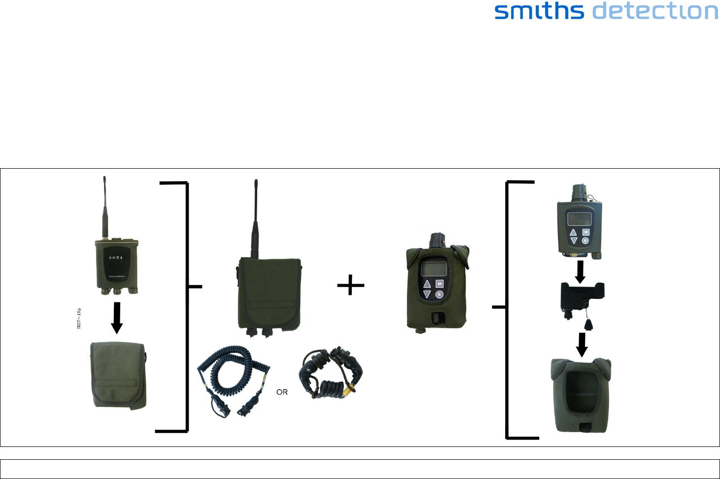
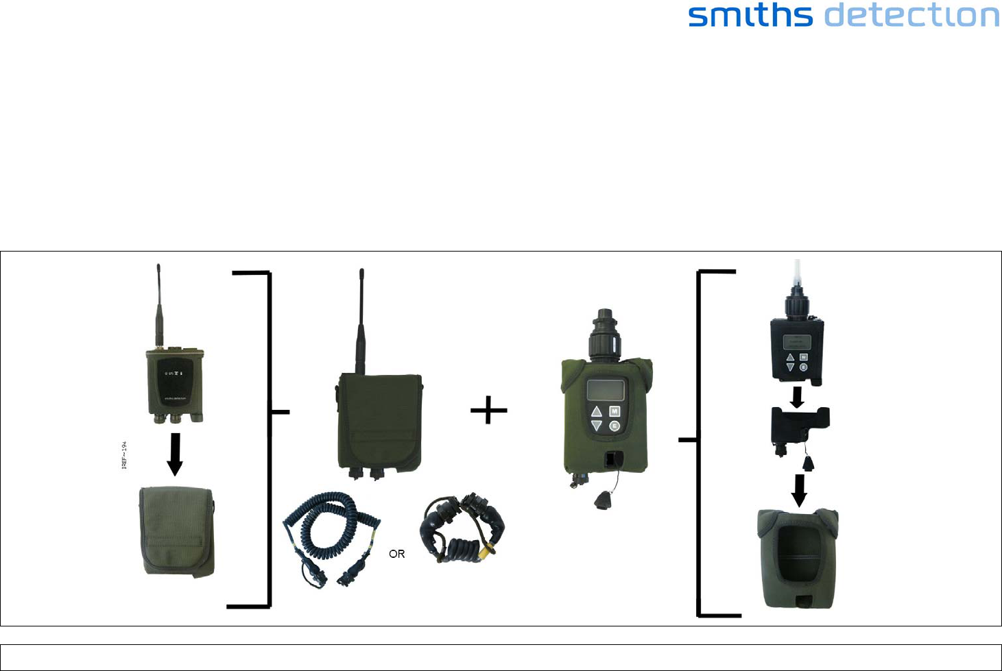
7 SETTING UP THE SENSOR NODE USING LCD3.3 AND POWER COMMS ADAPTOR
Unpack from the Sensor Node Transit Case:
• One Sensor Node
• One Battery Cassette
• 4 AA Batteries
• A Sensor node to detector comms cable (different types are available)
Also required (not part of Sensa-LINX): LCD3.3 detector with battery cassette and batteries and Power Comms Adaptor (PCA).
Figure 18 - Sensor Node with LCD3.3 and Power Comms Adaptor Kit
Page 21
Insert batteries into the Sensor Node and detector.
Figure 19 - Sensor Node (Battery Insertion)
Set up the LCD3.3 Detector and PCA. Refer to the LCD3.3 Detector Operators Manual and PCA Operators Manual for further information.
Page 22
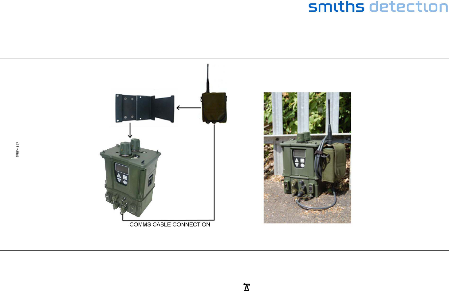
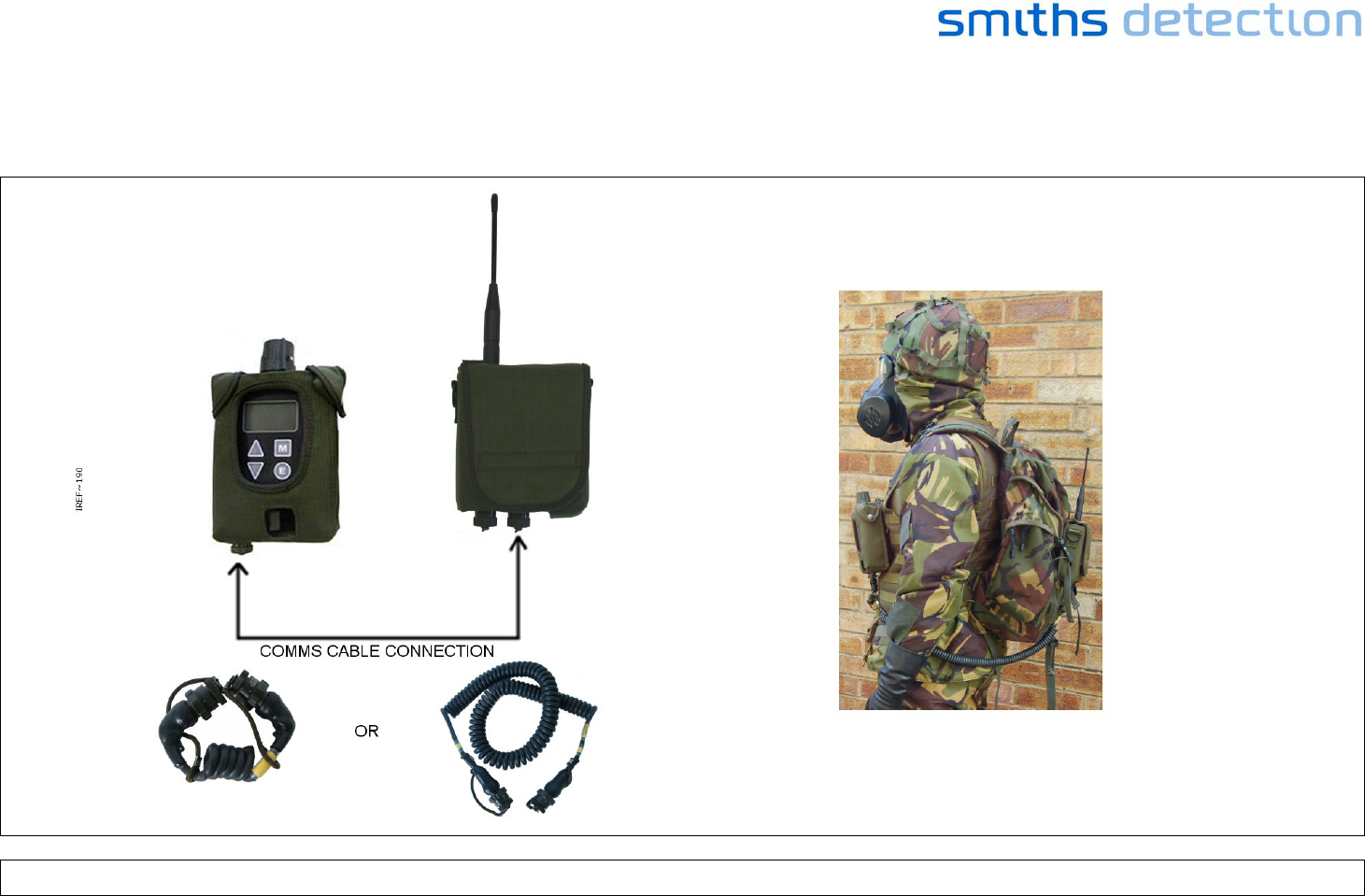
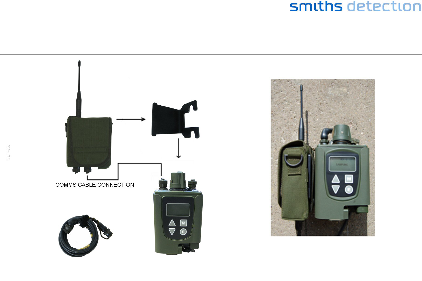
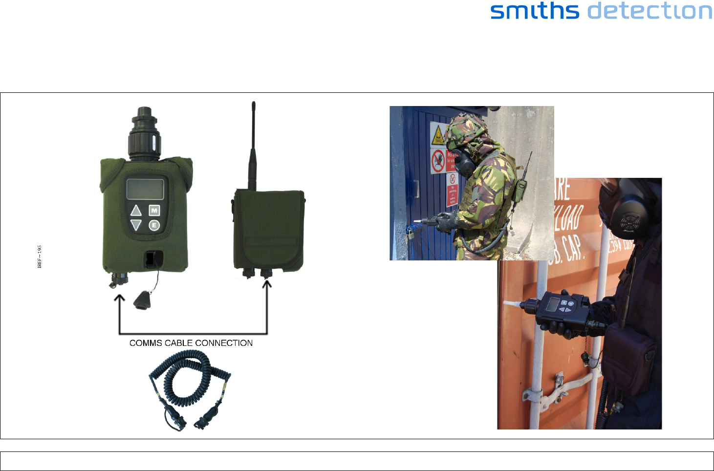
Connect the Sensor Node to the PCA with the data cable. Use optional accessories as required E.g. pouch for the Sensor Node, tripod and power
supply for sensor node. See full manual for details.
Figure 20 - Sensor Node with LCD3.3 and Power Comms Adaptor Set Up
Page 23
Turn on the detector and the Sensor Node. Confirm that the detector reports that the sensor node is connected (U displayed in the upper left hand
corner of the detector screen).
Confirm that the Sensor Node indicates communication with the Base Station ( LED flashes. Refer to the detector Operators Manual for further
information).
Figure 21 - Sensor Node with LCD3.3 and Power Comms Adaptor Set – in situ examples
Page 24
8 SETTING UP THE SENSOR NODE USING CAM XTR DETECTOR
Unpack from the Sensor Node Transit Case:
• One Sensor Node
• One Battery Cassette
• 4 AA Batteries
• A Sensor node to detector comms cable (different types are available)
Also required (not part of Sensa-LINX):CAM XTR detector with battery cassette and batteries.
Figure 22 - Sensor Node with CAM XTR and Dock and Pouch Kit
Page 25
Insert batteries into the Sensor Node and detector.
Figure 23 - Sensor Node (Battery Insertion)
Page 26
Connect the Sensor Node to the detector with the data cable. Use optional accessories as required E.g. pouch for the Sensor Node, tripod and power
supply for sensor node. See full manual for details.
Figure 24 - Sensor Node with CAM XTR and Dock and Pouch Set Up
Page 27
Turn on the detector and the Sensor Node. Confirm that the detector reports that the sensor node is connected (U displayed in the upper left hand
corner of the detector screen).
Confirm that the Sensor Node indicates communication with the Base Station ( LED flashes. Refer to the detector Operators Manual for further
information).
9 MONITORING THE SENSA-LINX NETWORK
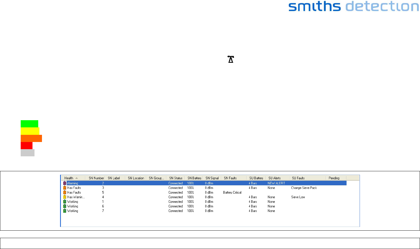
At the C2 computer, check the overall sensor nodes status in the list view.
Green Sensor Nodes are working normally.
Yellow Sensor Nodes have a warning.
Orange Sensor Nodes have a fault.
Red Sensor Nodes are alarming.
Grey Sensor Nodes are not communicating with the Basestation.
Figure 25 - Sensa-LINX Detector Networking System – C2 Application – Sensor Node Panel
Page 28
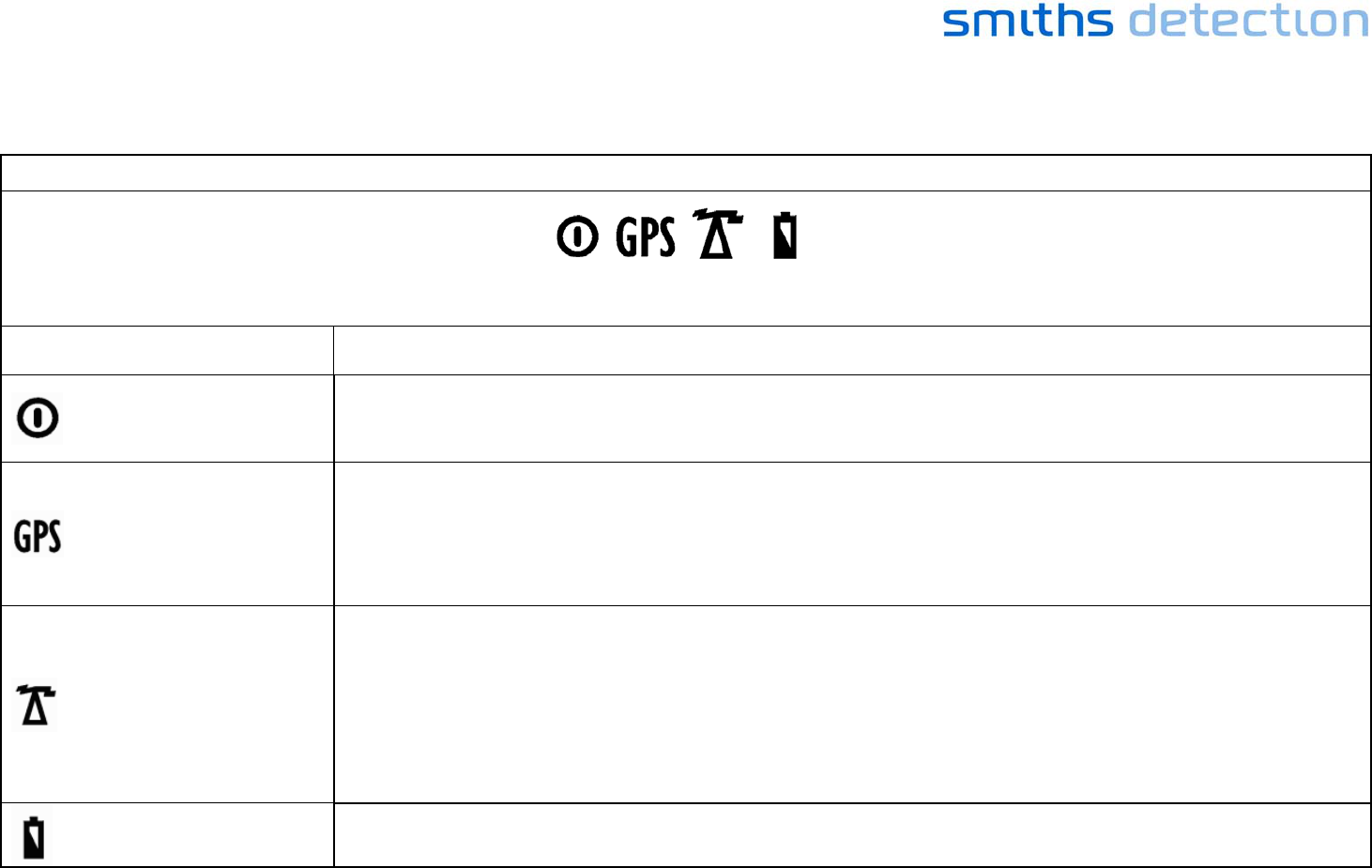
At the sensor location, check the sensor node status using the LEDs:
TABLE 1 LED Functions
Illuminated icons as viewed on front of Radio Modem
Icon and LED Function
Green LED - Power
On - External power.
Pulse - Battery Power.
Off – Radio Modem switched off or no power
Green LED – GPS, BIT
Indicator
Off – GPS device currently acquiring lock.
Single Pulse – GPS device currently in low power mode.
Double Pulse – GPS device currently has poor fix.
Triple Pulse – GPS device currently has good fix.
Long Pulse (3 seconds on, 1 second off) – GPS BIT errors detected
Green LED - Radio Link
Indicator
Short Triple Pulse - Strong radio link achieved and Sensor Node is transmitting.
Long Triple Pulse - Strong radio link achieved but Sensor Node is not transmitting.
Short Double Pulse - Good radio link achieved and Sensor Node is transmitting.
Long Double Pulse - Good radio link achieved but Sensor Node is not transmitting.
Short Single Pulse - Poor radio link has been achieved and Sensor Node is transmitting.
Long Single Pulse - Poor radio link has been achieved but Sensor Node is not transmitting.
Off - Radio link has not been achieved
Amber LED - Battery
Low Pulse - Low battery power.
Off - Good battery power or external power.
Page 29
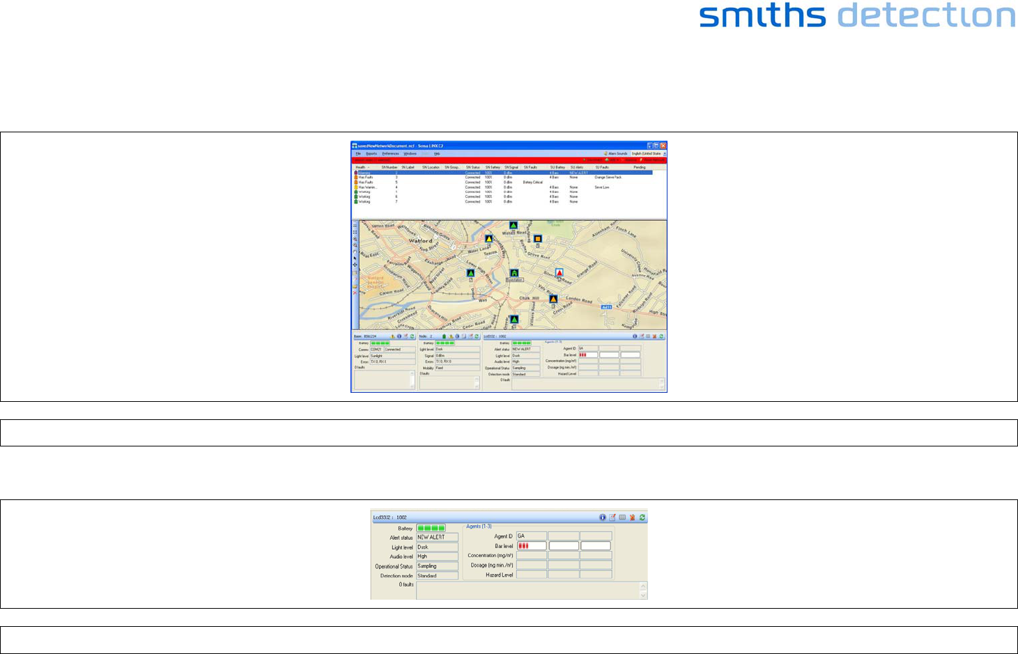
On the C2 computer, open a map file to see the sensor node locations.
Select “Windows” / “Show Map 1” and then browse to the location of a window file.
Figure 26 - Sensa-LINX Detector Networking System – C2 Application Main Window
Click on Sensor Nodes from the list or the map to check their detailed status.
Figure 27 - Sensa-LINX Detector Networking System – C2 Application – Sensor Node Information Panel
Page 30
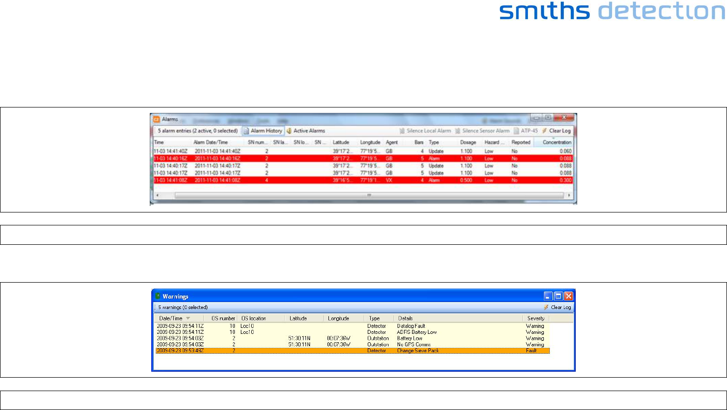
Open Alarm, Warnings or Events windows to see historical data:
Select “Windows / Alarms” - a list of alarms that occurred in the past.
Figure 28 - Sensa-LINX Detector Networking System – C2 Application– Alarms Window
Select “Windows / Warnings” - a list of errors that occurred.
Figure 29 - Sensa-LINX Detector Networking System – C2 Application – Warnings Window
Page 31
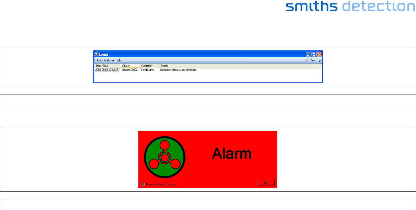
Select “Windows / Events” - a list of other events that are not alarms or warnings.
Figure 30 - Sensa-LINX Detector Networking System – C2 Application – Events Window
An alarm will cause a warning window to appear and a warning sound to occur.
Figure 31 - Sensa-LINX Detector Networking System – C2 Application – Alarm Pop Up
Page 32
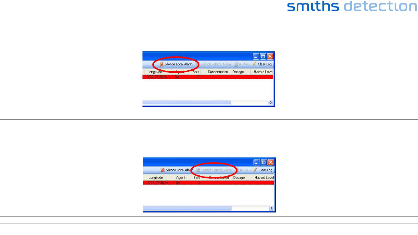
To silence the alarm at the PC (but leave the alarm sounding at the detector) Click “Silence Local Alarm” on the Alarms Window
Figure 32 - Sensa-LINX Detector Networking System – C2 Application Main Window –‘Silence Local Alarm’ Button
To silence the alarm at the Detector Click “Silence Sensor Alarm” on the Alarms Window or the Icon on the Sensor Pane
Figure 33 - Sensa-LINX Detector Networking System – C2 Application Main Window –‘Silence Sensor Alarm’ Button
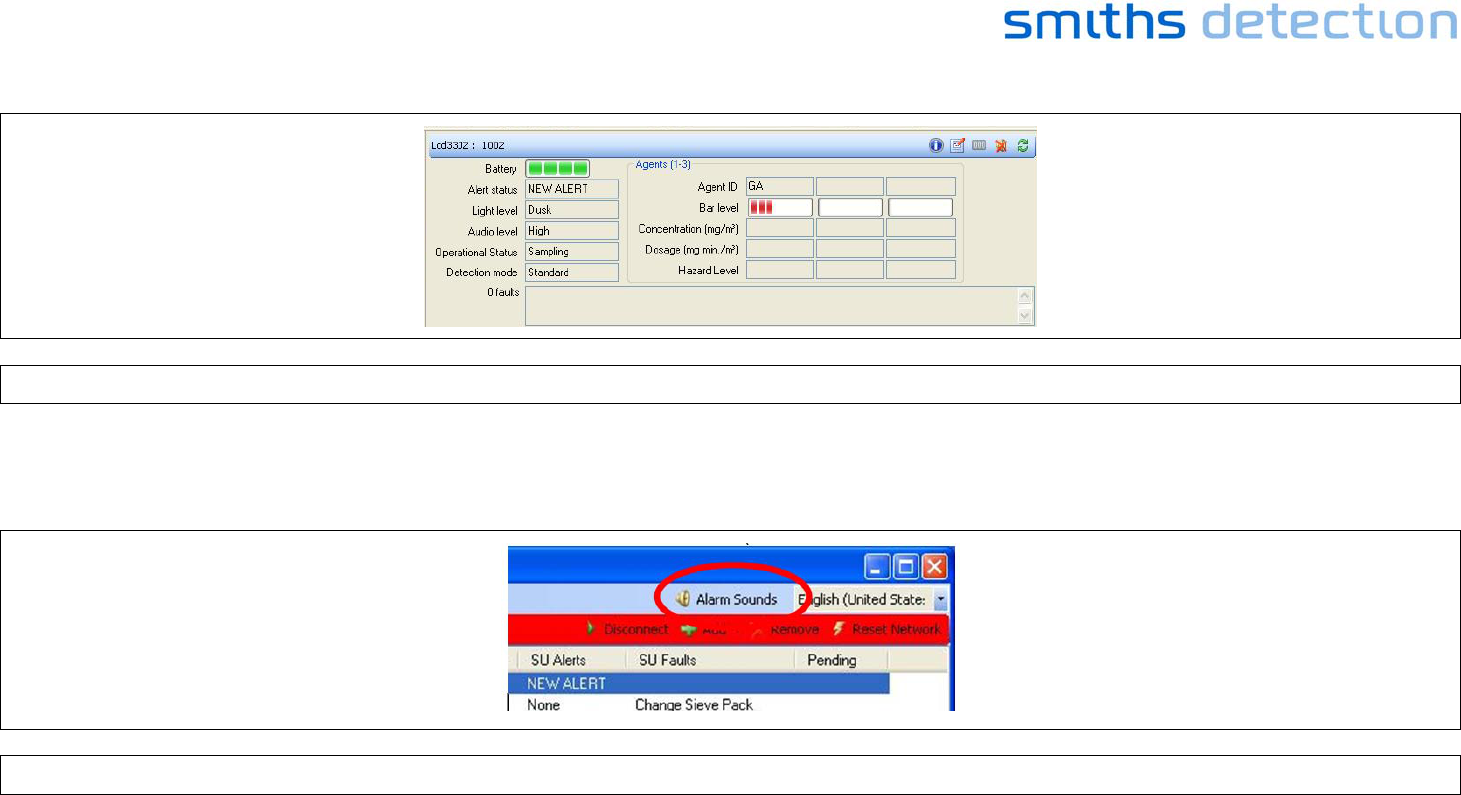
Page 33
Figure 34 - Sensa-LINX Detector Networking System – C2 Application – Sensor Node Panel in Alarm Condition
To prevent the audible alarm occurring at the PC in future:
Click the Icon on the Main Pane (or turn the PC volume down):
Figure 35 - Sensa-LINX Detector Networking System – C2 Application – Sensor Node ‘Alarm Sounds’ Button

Page 34
10 BASIC TROUBLESHOOTING
In the event that equipment appears not to be functioning correctly
1 Make sure that equipment has a suitable power supply either fresh batteries or an appropriate mains power supply.
2 Make sure that equipment is correctly set up and connected together.
3 Make sure that equipment is switched on.
4 Cycle the power on/start up routine.
If equipment still appears not to be functioning correctly refer to the Sensa LINX Operational Instructions/User Manual for further Fault Analysis
information.

Page 35

Page 36