2Wire Gateway Owners Manual Gateway_UG_5_29_21
to the manual f25ba819-09a7-4c89-a09d-4d0a1fb0fc2b
2015-02-05
: 2Wire 2Wire-Gateway--Owners-Manual-135242 2wire-gateway--owners-manual-135242 2wire pdf
Open the PDF directly: View PDF ![]() .
.
Page Count: 139 [warning: Documents this large are best viewed by clicking the View PDF Link!]
- Contents
- Introduction
- Networking Technology Overview
- Viewing Your System Summary
- Setting a System Password
- Viewing System Details
- Viewing Your Broadband Link Summary
- Using Broadband Diagnostics
- Viewing Statistics
- Using Advanced Settings
- Viewing Your Home Network Summary
- Monitoring Your Wireless Settings
- Configuring Advanced Settings
- Setting up a Private Network
- a. In the First DHCP Address field, enter the first DHCP address that you’ll be distributing over the private network.
- b. In the Last DHCP Address field, enter the last DHCP address that you’ll be distributing over the private network.
- c. In the Set DHCP Lease Time field, enter a value for the number of hours before the DHCP lease expires.
- Setting Up a Public Routed Subinterface
- Setting Up a Public Proxied Subnet
- Showing a Device as Inactive
- Setting up a Private Network
- Configuring the VoIP Phones
- Firewall Features
- Viewing Your Firewall Summary
- Hosting an Application
- Updating the Application Profile List
- Adding an Application Profile
- a. In the Protocol field, select the TCP or UDP radio button. If the application you are adding requires both, you must create a separate definition for each.
- b. In the Port (or Range) field, enter the port or port range the application uses. For example, some applications may require only one port to be opened (such as TCP port 500); others may require that all TCP ports from 600 to 1000 be opened.
- c. In the Protocol Timeout (seconds) field, you may optionally enter a value for the amount of time that can pass before the app...
- d. In the Map to Host Port field, enter a value that will map the port range you established in step b to the local computer. Fo...
- e. From the Application Type drop-down menu, select the application type. If you do not know the application type, select None (Default).
- f. To edit the application profile, click EDIT. The Edit Application screen appears. Make the necessary changes to the application profile and click DONE.
- g. To delete the application profile, click DELETE.
- Allowing all Applications (DMZplus)
- Viewing the Firewall Log
- Configuring the Firewall (Advanced)
- Accessing the MDC
- Using the MDC
- Remote Management Feature
- System Summary Page
- Broadband Link - Summary Page
- Broadband Link - Statistics Page
- Broadband Link - Detailed DSL Statistics Page
- Broadband Link - Configuration Page
- Local Network - Status Page
- Local Network - Statistics Page
- Local Network - Device List Page
- Local Network - Wireless Settings Page
- Local Network - Configuration Page
- Firewall - Settings Page
- Firewall - Detailed Information Page
- Firewall - Advanced Settings Page
- Voice Server - Summary Page
- Voice - Configure Server Page
- Troubleshooting - DSL Diagnostics Page
- Troubleshooting - Event Log Page
- Troubleshooting - Network Tests Page
- Troubleshooting - Upgrade History Page
- Troubleshooting - Resets Page
- Advanced - Syslog Settings Page
- Advanced - Provisioning Info Page
- Advanced - Configure Time Services Page
- Advanced - Configure Services Page
- Routing
- a. From the Windows desktop or the Start menu, right-click the My Network Places icon, then left-click Properties.
- b. Right-click the icon that represents the network connection to the gateway, and left-click Properties.
- c. Click Internet Protocol (TCP/IP), then click the Properties button.
- d. In the General tab, click the Use the following IP address radio button. In the IP address field, enter an IP address between...
- e. Click OK.
- f. If required, reboot the system for the changes to take effect.
- Changing Timeout Parameters
- Enabling Broadband Status Notification
- Enabling Missing DSL Filter Notification
- Enabling SIP Application Layer Gateway
- Changing the Upstream MTU
- Routing
- Advanced - Static Routes
- Advanced - DNS Resolve Page
- Advanced - Traffic Shaping Page
- Advanced - Link Manager States Page
- Advanced - Detailed Log Page
- A
- D
- E
- I
- L
- M
- N
- P
- R
- S
- T
- U
- V
- W
- Regulatory Information

2Wire Gateway
User Guide

Notice to Users
©2007 2Wire, Inc. All rights reserved. This manual in whole or in part, may not be reproduced, translated, or reduced to any machine-
readable form without prior written approval.
2WIRE PROVIDES NO WARRANTY WITH REGARD TO THIS MANUAL, THE SOFTWARE, OR OTHER INFORMATION CONTAINED HEREIN AND
HEREBY EXPRESSLY DISCLAIMS ANY IMPLIED WARRANTIES OF MERCHANTABILITY OR FITNESS FOR ANY PARTICULAR PURPOSE WITH
REGARD TO THIS MANUAL, THE SOFTWARE, OR SUCH OTHER INFORMATION, IN NO EVENT SHALL 2WIRE, INC. BE LIABLE FOR ANY
INCIDENTAL, CONSEQUENTIAL, OR SPECIAL DAMAGES, WHETHER BASED ON TORT, CONTRACT, OR OTHERWISE, ARISING OUT OF OR
IN CONNECTION WITH THIS MANUAL, THE SOFTWARE, OR OTHER INFORMATION CONTAINED HEREIN OR THE USE THEREOF.
2Wire, Inc. reserves the right to make any modification to this manual or the information contained herein at any time without notice.
The software described herein is governed by the terms of a separate user license agreement.
Updates and additions to software may require an additional charge. Subscriptions to online service providers may require a fee and
credit card information. Financial services may require prior arrangements with participating financial institutions.
2Wire, the 2Wire logo, and HomePortal are registered trademarks, and HyperG, Greenlight, FullPass, and GuestPass are trademarks
of 2Wire, Inc. All other trademarks are trademarks of their respective owners.
5100-000326-000 Rev C 08/2007

1
Contents
Introduction
Networking Technology Overview . . . . . . . . . . . . . . . . . . . . . . . . . . . . . . . . . . . . . . . . . . . . . . . . . . . . 1
System Tab
Viewing Your System Summary . . . . . . . . . . . . . . . . . . . . . . . . . . . . . . . . . . . . . . . . . . . . . . . . . . . . . . 2
Network at a Glance Panel . . . . . . . . . . . . . . . . . . . . . . . . . . . . . . . . . . . . . . . . . . . . . . . . . . . 3
System Area of the Network at a Glance Panel . . . . . . . . . . . . . . . . . . . . . . . . . . . . . . . . . 3
Broadband Link Area of the Network at a Glance Panel . . . . . . . . . . . . . . . . . . . . . . . . . . . 4
Home Network Area of the Network at a Glance Panel . . . . . . . . . . . . . . . . . . . . . . . . . . . . 4
Enabling Enhanced Services . . . . . . . . . . . . . . . . . . . . . . . . . . . . . . . . . . . . . . . . . . . . . . . . . . 5
Web Remote Access . . . . . . . . . . . . . . . . . . . . . . . . . . . . . . . . . . . . . . . . . . . . . . . . . . . . 5
Firewall Monitor . . . . . . . . . . . . . . . . . . . . . . . . . . . . . . . . . . . . . . . . . . . . . . . . . . . . . . . .5
Parental Controls . . . . . . . . . . . . . . . . . . . . . . . . . . . . . . . . . . . . . . . . . . . . . . . . . . . . . . 5
Setting a System Password . . . . . . . . . . . . . . . . . . . . . . . . . . . . . . . . . . . . . . . . . . . . . . . . . . . . . . . . 6
Resetting the System Password . . . . . . . . . . . . . . . . . . . . . . . . . . . . . . . . . . . . . . . . . . . . . . . 7
Changing Your Time Zone Settings . . . . . . . . . . . . . . . . . . . . . . . . . . . . . . . . . . . . . . . . . . 8
Viewing System Details . . . . . . . . . . . . . . . . . . . . . . . . . . . . . . . . . . . . . . . . . . . . . . . . . . . . . . . . . . . 9
Broadband Link Tab
Viewing Your Broadband Link Summary . . . . . . . . . . . . . . . . . . . . . . . . . . . . . . . . . . . . . . . . . . . . . . .10
Connection Status . . . . . . . . . . . . . . . . . . . . . . . . . . . . . . . . . . . . . . . . . . . . . . . . . . . . . . . .10
Connection Speed . . . . . . . . . . . . . . . . . . . . . . . . . . . . . . . . . . . . . . . . . . . . . . . . . . . . . . . .11
Connection Information . . . . . . . . . . . . . . . . . . . . . . . . . . . . . . . . . . . . . . . . . . . . . . . . . . . . 11
Finding Your Hardware Address . . . . . . . . . . . . . . . . . . . . . . . . . . . . . . . . . . . . . . . . . . . 11
Connection Details . . . . . . . . . . . . . . . . . . . . . . . . . . . . . . . . . . . . . . . . . . . . . . . . . . . . . . .12
Monitor Internet Connection . . . . . . . . . . . . . . . . . . . . . . . . . . . . . . . . . . . . . . . . . . . . . . . . . 16
Test Connection Speed . . . . . . . . . . . . . . . . . . . . . . . . . . . . . . . . . . . . . . . . . . . . . . . . . . . . 16
Using Broadband Diagnostics . . . . . . . . . . . . . . . . . . . . . . . . . . . . . . . . . . . . . . . . . . . . . . . . . . . . . . 16
Viewing Statistics . . . . . . . . . . . . . . . . . . . . . . . . . . . . . . . . . . . . . . . . . . . . . . . . . . . . . . . . . . . . . . 17
Using Advanced Settings . . . . . . . . . . . . . . . . . . . . . . . . . . . . . . . . . . . . . . . . . . . . . . . . . . . . . . . . . 20
Modifying DSL and ATM Settings . . . . . . . . . . . . . . . . . . . . . . . . . . . . . . . . . . . . . . . . . . . . . 21
Modifying Broadband Connection Settings . . . . . . . . . . . . . . . . . . . . . . . . . . . . . . . . . . . . . . . 22
Modifying the Hardware Address . . . . . . . . . . . . . . . . . . . . . . . . . . . . . . . . . . . . . . . . . . . . . 22
Enabling Hostname Override . . . . . . . . . . . . . . . . . . . . . . . . . . . . . . . . . . . . . . . . . . . . . . . . 22
Modifying the Broadband IP . . . . . . . . . . . . . . . . . . . . . . . . . . . . . . . . . . . . . . . . . . . . . . . . . 23
Modifying the Broadband DNS . . . . . . . . . . . . . . . . . . . . . . . . . . . . . . . . . . . . . . . . . . . . . . . 23
Home Network Tab
Viewing Your Home Network Summary . . . . . . . . . . . . . . . . . . . . . . . . . . . . . . . . . . . . . . . . . . . . . . .24
Understanding the Local Devices Panel . . . . . . . . . . . . . . . . . . . . . . . . . . . . . . . . . . . . . . . . . 24
Understanding the Status at a Glance Panel . . . . . . . . . . . . . . . . . . . . . . . . . . . . . . . . . . . . . 26
Monitoring Your Wireless Settings . . . . . . . . . . . . . . . . . . . . . . . . . . . . . . . . . . . . . . . . . . . . . . . . . . 26
Customizing Security Settings . . . . . . . . . . . . . . . . . . . . . . . . . . . . . . . . . . . . . . . . . . . . . . . 28
Configuring MAC Filtering . . . . . . . . . . . . . . . . . . . . . . . . . . . . . . . . . . . . . . . . . . . . . . . . . . . 29
Configuring Additional Settings . . . . . . . . . . . . . . . . . . . . . . . . . . . . . . . . . . . . . . . . . . . . . . . 29
Configuring Advanced Settings . . . . . . . . . . . . . . . . . . . . . . . . . . . . . . . . . . . . . . . . . . . . . . . . . . . . . 30

Contents
2
Setting up a Private Network . . . . . . . . . . . . . . . . . . . . . . . . . . . . . . . . . . . . . . . . . . . . . . . . 30
Setting Up a Public Routed Subinterface . . . . . . . . . . . . . . . . . . . . . . . . . . . . . . . . . . . . . . . . 32
Setting Up a Public Proxied Subnet . . . . . . . . . . . . . . . . . . . . . . . . . . . . . . . . . . . . . . . . . . . . 33
Selecting a Default DHCP Pool . . . . . . . . . . . . . . . . . . . . . . . . . . . . . . . . . . . . . . . . . . . . 33
Showing a Device as Inactive . . . . . . . . . . . . . . . . . . . . . . . . . . . . . . . . . . . . . . . . . . . . . . . . 33
VoIP Network Tab
Configuring the VoIP Phones . . . . . . . . . . . . . . . . . . . . . . . . . . . . . . . . . . . . . . . . . . . . . . . . . . . . . . 34
Firewall Tab
Firewall Features . . . . . . . . . . . . . . . . . . . . . . . . . . . . . . . . . . . . . . . . . . . . . . . . . . . . . . . . . . . . . . . 37
Viewing Your Firewall Summary . . . . . . . . . . . . . . . . . . . . . . . . . . . . . . . . . . . . . . . . . . . . . . . . . . . . . 38
Hosting an Application . . . . . . . . . . . . . . . . . . . . . . . . . . . . . . . . . . . . . . . . . . . . . . . . . . . . . . . . . . . 39
Updating the Application Profile List . . . . . . . . . . . . . . . . . . . . . . . . . . . . . . . . . . . . . . . . . . . 41
Adding an Application Profile . . . . . . . . . . . . . . . . . . . . . . . . . . . . . . . . . . . . . . . . . . . . . . . . 41
Allowing all Applications (DMZplus) . . . . . . . . . . . . . . . . . . . . . . . . . . . . . . . . . . . . . . . . . . . . . . . . . . 44
Viewing the Firewall Log . . . . . . . . . . . . . . . . . . . . . . . . . . . . . . . . . . . . . . . . . . . . . . . . . . . . . . . . . . 46
Configuring the Firewall (Advanced) . . . . . . . . . . . . . . . . . . . . . . . . . . . . . . . . . . . . . . . . . . . . . . . . . . 48
Enabling Advanced Security . . . . . . . . . . . . . . . . . . . . . . . . . . . . . . . . . . . . . . . . . . . . . . . . . 49
Stealth Mode . . . . . . . . . . . . . . . . . . . . . . . . . . . . . . . . . . . . . . . . . . . . . . . . . . . . . . . . 49
Block Ping . . . . . . . . . . . . . . . . . . . . . . . . . . . . . . . . . . . . . . . . . . . . . . . . . . . . . . . . . . 51
Strict UDP Session Control . . . . . . . . . . . . . . . . . . . . . . . . . . . . . . . . . . . . . . . . . . . . . . 52
Allowing Inbound and Outbound Traffic . . . . . . . . . . . . . . . . . . . . . . . . . . . . . . . . . . . . . . . . . 53
Disabling Attack Detection . . . . . . . . . . . . . . . . . . . . . . . . . . . . . . . . . . . . . . . . . . . . . . . . . . 53
Management and Diagnostic Console
Accessing the MDC . . . . . . . . . . . . . . . . . . . . . . . . . . . . . . . . . . . . . . . . . . . . . . . . . . . . . . . . . . . . . 56
Using the MDC . . . . . . . . . . . . . . . . . . . . . . . . . . . . . . . . . . . . . . . . . . . . . . . . . . . . . . . . . . . . . . . . 56
System Summary Page . . . . . . . . . . . . . . . . . . . . . . . . . . . . . . . . . . . . . . . . . . . . . . . . . . . . 58
Broadband Link Pages . . . . . . . . . . . . . . . . . . . . . . . . . . . . . . . . . . . . . . . . . . . . . . . . . . . . . 58
Local Network Pages . . . . . . . . . . . . . . . . . . . . . . . . . . . . . . . . . . . . . . . . . . . . . . . . . . . . . . 58
Firewall Pages . . . . . . . . . . . . . . . . . . . . . . . . . . . . . . . . . . . . . . . . . . . . . . . . . . . . . . . . . . . 58
Voice Pages . . . . . . . . . . . . . . . . . . . . . . . . . . . . . . . . . . . . . . . . . . . . . . . . . . . . . . . . . . . . 58
Troubleshooting Pages . . . . . . . . . . . . . . . . . . . . . . . . . . . . . . . . . . . . . . . . . . . . . . . . . . . . 58
Advanced Pages . . . . . . . . . . . . . . . . . . . . . . . . . . . . . . . . . . . . . . . . . . . . . . . . . . . . . . . . .58
Remote Management Feature . . . . . . . . . . . . . . . . . . . . . . . . . . . . . . . . . . . . . . . . . . . . . . . . . . . . . 59
System Summary Page . . . . . . . . . . . . . . . . . . . . . . . . . . . . . . . . . . . . . . . . . . . . . . . . . . . . . . . . . . 60
Broadband Link - Summary Page . . . . . . . . . . . . . . . . . . . . . . . . . . . . . . . . . . . . . . . . . . . . . . . . . . . 62
Broadband Link - Statistics Page . . . . . . . . . . . . . . . . . . . . . . . . . . . . . . . . . . . . . . . . . . . . . . . . . . . 65
Broadband Link - Detailed DSL Statistics Page . . . . . . . . . . . . . . . . . . . . . . . . . . . . . . . . . . . . . . . . .67
Broadband Link - Configuration Page . . . . . . . . . . . . . . . . . . . . . . . . . . . . . . . . . . . . . . . . . . . . . . . . . 70
Modifying DSL and ATM Settings . . . . . . . . . . . . . . . . . . . . . . . . . . . . . . . . . . . . . . . . . . . . . 71
Modifying Internet Connection and Authentication Settings . . . . . . . . . . . . . . . . . . . . . . . . . . . 71
Modifying Hardware Address . . . . . . . . . . . . . . . . . . . . . . . . . . . . . . . . . . . . . . . . . . . . . . . . 72
Modifying Internet Address Settings . . . . . . . . . . . . . . . . . . . . . . . . . . . . . . . . . . . . . . . . . . . 72
Modifying DNS Information . . . . . . . . . . . . . . . . . . . . . . . . . . . . . . . . . . . . . . . . . . . . . . . . . . 72
Local Network - Status Page . . . . . . . . . . . . . . . . . . . . . . . . . . . . . . . . . . . . . . . . . . . . . . . . . . . . . . . 73
Local Network - Statistics Page . . . . . . . . . . . . . . . . . . . . . . . . . . . . . . . . . . . . . . . . . . . . . . . . . . . . 75
Local Network - Device List Page . . . . . . . . . . . . . . . . . . . . . . . . . . . . . . . . . . . . . . . . . . . . . . . . . . . 77

Contents
3
Local Network - Wireless Settings Page . . . . . . . . . . . . . . . . . . . . . . . . . . . . . . . . . . . . . . . . . . . . . . . 78
Customizing Security Settings . . . . . . . . . . . . . . . . . . . . . . . . . . . . . . . . . . . . . . . . . . . . . . . 79
Additional Settings . . . . . . . . . . . . . . . . . . . . . . . . . . . . . . . . . . . . . . . . . . . . . . . . . . . . . . . 79
Local Network - Configuration Page . . . . . . . . . . . . . . . . . . . . . . . . . . . . . . . . . . . . . . . . . . . . . . . . . . 80
Private Network Settings . . . . . . . . . . . . . . . . . . . . . . . . . . . . . . . . . . . . . . . . . . . . . . . . . . . 80
Public Routed Subinterface Settings . . . . . . . . . . . . . . . . . . . . . . . . . . . . . . . . . . . . . . . . . . . 81
Public Proxied Subnet Settings . . . . . . . . . . . . . . . . . . . . . . . . . . . . . . . . . . . . . . . . . . . . . . . 81
Display Settings . . . . . . . . . . . . . . . . . . . . . . . . . . . . . . . . . . . . . . . . . . . . . . . . . . . . . . . . . 81
Enable Router Behind Router Alert . . . . . . . . . . . . . . . . . . . . . . . . . . . . . . . . . . . . . . . . . . . . 81
Firewall - Settings Page . . . . . . . . . . . . . . . . . . . . . . . . . . . . . . . . . . . . . . . . . . . . . . . . . . . . . . . . . . 82
Hosting an Application . . . . . . . . . . . . . . . . . . . . . . . . . . . . . . . . . . . . . . . . . . . . . . . . . . . . .83
Creating an Application Profile . . . . . . . . . . . . . . . . . . . . . . . . . . . . . . . . . . . . . . . . . . . . . . . 83
Allowing all applications . . . . . . . . . . . . . . . . . . . . . . . . . . . . . . . . . . . . . . . . . . . . . . . . . . . .85
Firewall - Detailed Information Page . . . . . . . . . . . . . . . . . . . . . . . . . . . . . . . . . . . . . . . . . . . . . . . . . 86
Pinholes . . . . . . . . . . . . . . . . . . . . . . . . . . . . . . . . . . . . . . . . . . . . . . . . . . . . . . . . . . . . . . . 86
NAT Sessions . . . . . . . . . . . . . . . . . . . . . . . . . . . . . . . . . . . . . . . . . . . . . . . . . . . . . . . . . . . 86
Firewall - Advanced Settings Page . . . . . . . . . . . . . . . . . . . . . . . . . . . . . . . . . . . . . . . . . . . . . . . . . . . 87
Enabling Security Features . . . . . . . . . . . . . . . . . . . . . . . . . . . . . . . . . . . . . . . . . . . . . . . . . . 88
Controlling Inbound and Outbound Traffic . . . . . . . . . . . . . . . . . . . . . . . . . . . . . . . . . . . . . . . 88
Disabling Attack Detection . . . . . . . . . . . . . . . . . . . . . . . . . . . . . . . . . . . . . . . . . . . . . . . . . . 88
Enabling Full Logging . . . . . . . . . . . . . . . . . . . . . . . . . . . . . . . . . . . . . . . . . . . . . . . . . . . . . .88
Voice Server - Summary Page . . . . . . . . . . . . . . . . . . . . . . . . . . . . . . . . . . . . . . . . . . . . . . . . . . . . . . 89
Voice - Configure Server Page . . . . . . . . . . . . . . . . . . . . . . . . . . . . . . . . . . . . . . . . . . . . . . . . . . . . . . 90
Voice - Associate Server Page . . . . . . . . . . . . . . . . . . . . . . . . . . . . . . . . . . . . . . . . . . . . . . . . . . . . . 92
Troubleshooting - DSL Diagnostics Page . . . . . . . . . . . . . . . . . . . . . . . . . . . . . . . . . . . . . . . . . . . . . . 93
Analyzing General Information . . . . . . . . . . . . . . . . . . . . . . . . . . . . . . . . . . . . . . . . . . . . . . . 94
Reviewing Training History . . . . . . . . . . . . . . . . . . . . . . . . . . . . . . . . . . . . . . . . . . . . . . . . . . 95
Reviewing Bitloading . . . . . . . . . . . . . . . . . . . . . . . . . . . . . . . . . . . . . . . . . . . . . . . . . . . . . .97
Troubleshooting - Event Log Page . . . . . . . . . . . . . . . . . . . . . . . . . . . . . . . . . . . . . . . . . . . . . . . . . . . 98
Troubleshooting - Network Tests Page . . . . . . . . . . . . . . . . . . . . . . . . . . . . . . . . . . . . . . . . . . . . . . . 100
Troubleshooting - Upgrade History Page . . . . . . . . . . . . . . . . . . . . . . . . . . . . . . . . . . . . . . . . . . . . . 102
Troubleshooting - Resets Page . . . . . . . . . . . . . . . . . . . . . . . . . . . . . . . . . . . . . . . . . . . . . . . . . . . . 103
Advanced - Syslog Settings Page . . . . . . . . . . . . . . . . . . . . . . . . . . . . . . . . . . . . . . . . . . . . . . . . . . 105
Advanced - Provisioning Info Page . . . . . . . . . . . . . . . . . . . . . . . . . . . . . . . . . . . . . . . . . . . . . . . . . . 106
Advanced - Configure Time Services Page . . . . . . . . . . . . . . . . . . . . . . . . . . . . . . . . . . . . . . . . . . . . 108
Advanced - Configure Services Page . . . . . . . . . . . . . . . . . . . . . . . . . . . . . . . . . . . . . . . . . . . . . . . . 110
Routing . . . . . . . . . . . . . . . . . . . . . . . . . . . . . . . . . . . . . . . . . . . . . . . . . . . . . . . . . . . . . . 110
Changing Timeout Parameters . . . . . . . . . . . . . . . . . . . . . . . . . . . . . . . . . . . . . . . . . . . . . . 113
Enabling Broadband Status Notification . . . . . . . . . . . . . . . . . . . . . . . . . . . . . . . . . . . . . . . 113
Enabling Missing DSL Filter Notification . . . . . . . . . . . . . . . . . . . . . . . . . . . . . . . . . . . . . . . 113
Enabling SIP Application Layer Gateway . . . . . . . . . . . . . . . . . . . . . . . . . . . . . . . . . . . . . . . 113
Changing the Upstream MTU . . . . . . . . . . . . . . . . . . . . . . . . . . . . . . . . . . . . . . . . . . . . . . . 113
Advanced - Static Routes . . . . . . . . . . . . . . . . . . . . . . . . . . . . . . . . . . . . . . . . . . . . . . . . . . . . . . . . 115
Advanced - DNS Resolve Page . . . . . . . . . . . . . . . . . . . . . . . . . . . . . . . . . . . . . . . . . . . . . . . . . . . . 117
Advanced - Traffic Shaping Page . . . . . . . . . . . . . . . . . . . . . . . . . . . . . . . . . . . . . . . . . . . . . . . . . . . 118
Advanced - Link Manager States Page . . . . . . . . . . . . . . . . . . . . . . . . . . . . . . . . . . . . . . . . . . . . . . . 119
Advanced - Detailed Log Page . . . . . . . . . . . . . . . . . . . . . . . . . . . . . . . . . . . . . . . . . . . . . . . . . . . . 122
Glossary

1
Introduction
The 2Wire gateway allows you to create a network with your computers and peripheral devices. Following
are just a few of the benefits derived from using the 2Wire gateway to network your home or office.
High performance integrated modem. 2Wire’s technology improves DSL1 performance, especially for
homes further away from the local exchange. It also minimizes common interference found when other
devices (such as dimmer switches or fluorescent lighting) are in contact with the DSL line.
Super-fast router. The 2Wire gateway’s router provides the fastest data transfer speeds available between
your network and the Internet. The high-performance router distributes data seamlessly to all of the
computers on your network, without a dramatic loss of performance or speed.
Professional-grade firewall. The 2Wire gateway firewall includes both standard NAT/PAT security and
Stateful Packet Inspection to defend against Denial of Service Internet attacks.
Flexible networking. The 2Wire gateway includes a variety of home networking technologies in one box:
Ethernet, direct USB, and HyperG wireless2. Use any or all of the following technologies to create a network
with your computers and peripherals.
Networking Technology Overview
Ethernet. Ethernet is a local area network (LAN) technology that transmits information between computers
at speeds of 10 or 100 Mbps. 2Wire gateways have either 1 or 4 Ethernet ports for directly connecting
computers or devices. If your home or office is wired for Ethernet, you can use the Ethernet interface(s) on
the gateway to create a broadband network.
USB. The 2Wire gateway’s USB 1.1 port allows you to directly connect a computer or other network-ready
device.
Wireless. The 2Wire gateway includes an integrated wireless access point, which allows users to roam
wirelessly throughout the home or office. 2Wire’s high-powered wireless technology virtually eliminates
wireless “coldspots” in the home. The 2Wire gateway’s high power 400mW transmitter ensures that users
benefit from increased wireless bandwidth throughout the coverage area. In addition, the 2Wire gateway
employs a special triple antenna design. The third antenna is used only for transmitting packets, thus
mitigating the power loss associated with switching the antenna use back and forth between transmit and
receive. This results in greater access point sensitivity, as antenna placement can be better optimized with
a dedicated set of receive-only antennas.
1. The 200 series gateways connect via Ethernet.
2. Some interfaces are not available on specific models.
2
System Tab
This chapter describes the 2Wire gateway System features.
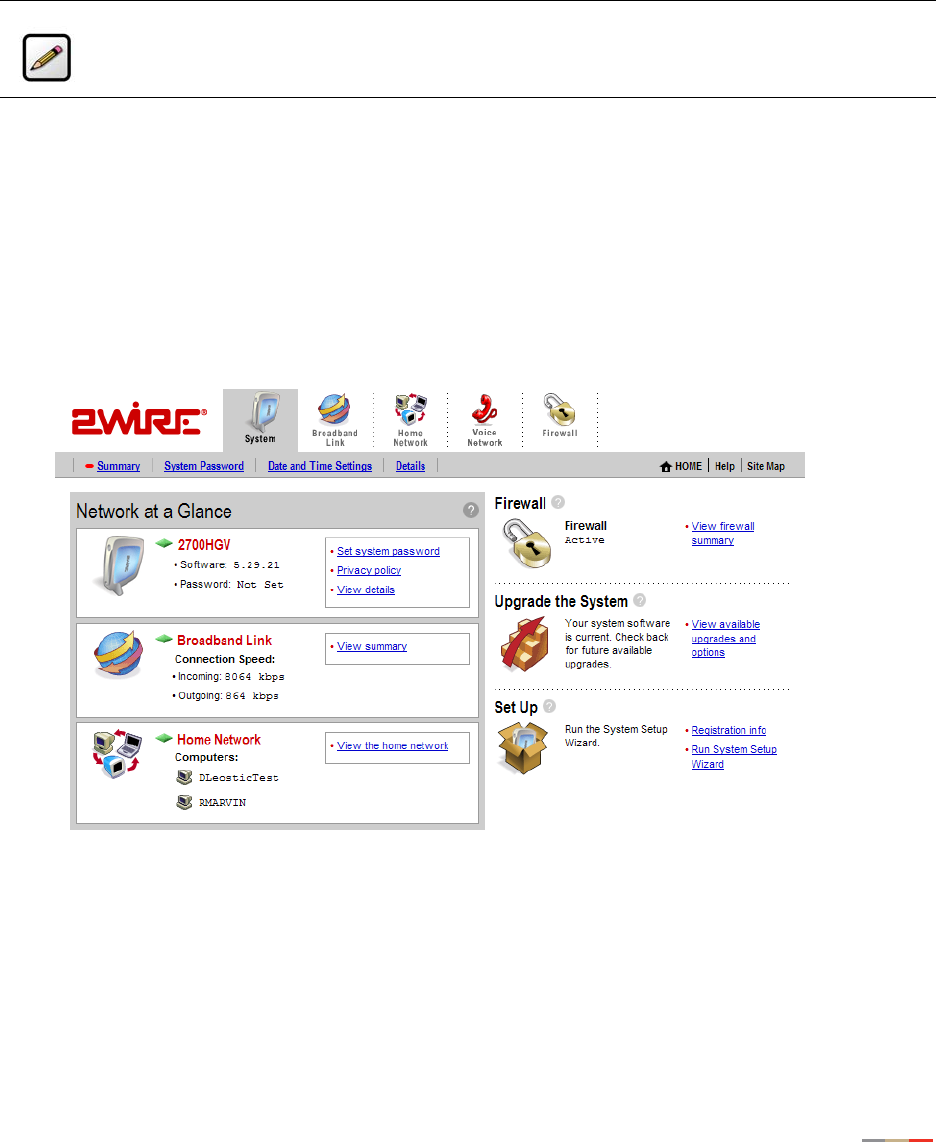
Viewing Your System Summary
The System Summary page provides general information and links to your system’s most commonly used
features.
To access the System Summary page:
• Open a Web browser and access the gateway user interface by entering
http://gateway.2wire.net.
• Click the System tab to open the System Summary page.
Figure 1. System Summary Page
Note: 2Wire recommends that you use Internet Explorer 5.5 (or higher) or Netscape 6 (or
higher).
System Tab
3
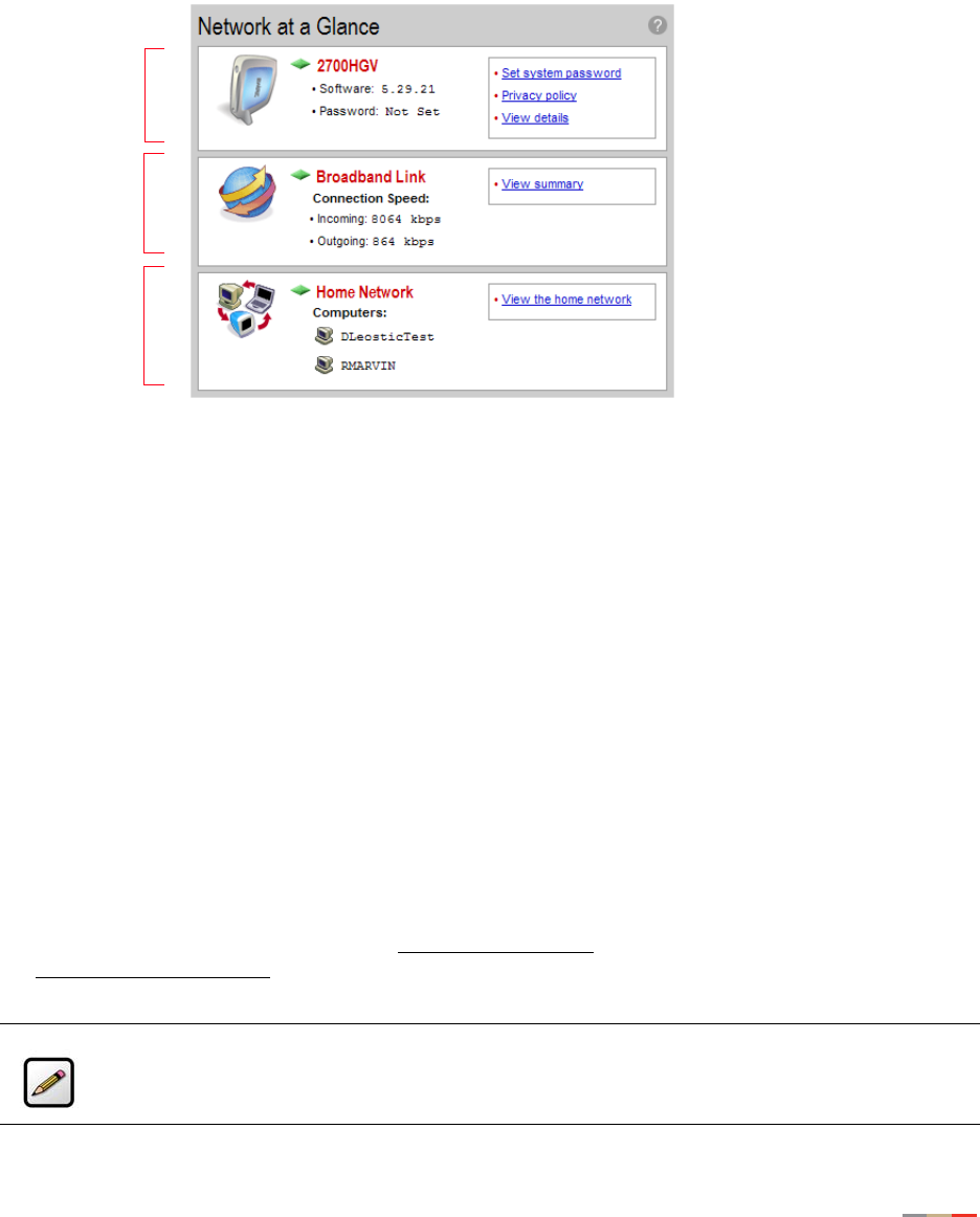
Network at a Glance Panel
The Network at a Glance panel provides a summary of the System, Broadband Link, and Home Network
states of your gateway.
Figure 2. Network at a Glance Panel
System Area of the Network at a Glance Panel
The System area of the Network at a Glance panel displays your 2Wire gateway model name, the version of
gateway software that you are using, and the status of your gateway password.
The diamond symbol in this area indicates the gateway’s POWER light status and corresponds to the Power
light on the front of your gateway.
The following table shows a list of possible POWER light states and their associated meanings:
If you have not set a system password, the Set system password link displays. If you have set a password,
the Change system password link displays. You must enter the system password whenever you change
system settings.
Power Light Condition
Off Power is not being supplied to the system. The power supply is not
plugged in correctly, or the power adapter has malfunctioned.
Blinking Green The system is performing a self test.
Solid Green Power is on.
Blinking Orange The gateway is undergoing a software upgrade.
Solid Red System error. Contact Technical Support.
Note: For additional information, refer to “Setting a System Password” on page 6.
System Area
Home
Network Area
Broadband
Link Area

System Tab
4
Click the Privacy policy link to review the 2Wire privacy policy.
Broadband Link Area of the Network at a Glance Panel
The Broadband Link area of the Network at a Glance panel displays the overall status of your gateway’s
physical connectivity.
The diamond symbol in this area indicates the overall status of the broadband link and corresponds to the
Internet light on the front of your gateway.
The following table shows a list of possible BROADBAND LINK light states and their associated meanings:
Connection Speed displays the broadband speed for which DSL is configured by your ISP. Both the Incoming
(or Downstream — from your service provider to your system) and Outgoing (or Upstream — from your
system to your service provider) connection rates are shown. The actual throughput of your Internet
connection rate (such as downloading a file from a Web site) will be somewhat less, because of the
overhead required to send information over the Internet.
Accessing the Broadband Link Summary Page
The Broadband Link Summary page provides general information about the current status of your
broadband link connection and your system configuration. To access the Broadband Link Summary page,
click the Broadband Link icon or the View summary link.
Launching the 2Wire Bandwidth Meter
The Bandwidth Meter measures the maximum data throughput obtained from 2Wire’s Web site to your
system. Because it tests the speed over the Internet, your results may vary, depending on Internet
conditions.
To launch the 2Wire Bandwidth Meter, click the Test connection speed link.
Home Network Area of the Network at a Glance Panel
The Home Network area of the Network at a Glance panel displays your system’s LOCAL NETWORK light
status and a list of the devices currently connected to your local network.
The diamond symbol in this area indicates the overall status of the network and corresponds to the
Ethernet, USB, or Wireless light on the front of your gateway.
Broadband Link Light Condition
Off The gateway has been unable to detect a DSL
signal.
DSL signal detected; the gateway is
attempting to train.
Solid Green The gateway is fully connected to your
broadband service(s).
Ethernet, USB, or Wireless Light Condition
Off The gateway is powered off or booting up.
Solid Green Device(s) connected via Ethernet, USB, or Wireless.

System Tab
5
Accessing the Home Network Summary Page
The Home Network Summary page displays information about the devices installed on your network. To
access the Home Network Summary page, click the View the home network link.
Enabling Enhanced Services
2Wire provides a suite of enhanced services: Web Remote Access, Firewall Monitor, and Parental Controls.
If your service provider offers these enhanced services, links to set them up are available on the gateway
Home page. Following is a brief description of these services.
Web Remote Access
The Web Remote Access enhanced service allows you to access your home computer files from remote
locations using any standard Web browser. Web Remote Access authenticates and encrypts access
between the Web browser and the 2Wire gateway, enabling you to securely access and download important
files or manage other enhanced services such as Parental Controls or Firewall Monitor.
You can optionally define a unique Web Domain Name during setup (for example, http://
myname.accessmyhome.net), making it easy for users that are allowed to access the home network to
manage the gateway when away from the home.
For additional information, please refer to the Web Remote Access User Guide.
Firewall Monitor
The 2Wire Firewall Monitor enhanced service extends the professional-grade firewall capabilities of your
2Wire gateway by continuously assessing threats to your home network. Firewall Monitor allows you to:
• Automatically download updates to your firewall software to protect against new threats.
• Receive on-screen notification to alert you of network attacks.
• Review details about attacks blocked and the source of the attacks.
For additional information, please refer to the Firewall Monitor User Guide.
Parental Controls
The 2Wire Parental Controls enhanced service offers two features that allow parents to maintain control
over what their children can access on the Internet, and how often: Content Screening and Internet Access
Controls.
Content Screening allows you to protect your children from Websites with questionable content. You control
what sites or types of sites your child can and cannot access. Internet Access Control gives you power to
decide when your child can use the Internet and allows you to restrict Internet access by day of week and
time of day.
For additional information, please refer to the Parental Controls User Guide.
System Tab
6
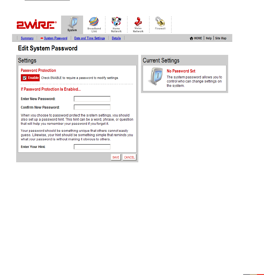
Setting a System Password
Setting a system password protects your gateway settings from being modified or changed by someone who
has not been given permission to do so. After setting a system password, you will be required to enter it
whenever you attempt to access a gateway configuration page — for example, if you try to change the
gateway’s broadband connection settings or upgrade the gateway software. If a password has not been set,
a reminder notice is displayed when you attempt to access pages where settings can be changed.
To set your system password:
• Open a Web browser and access the gateway user interface by entering
http://gateway.2wire.net.
• Click the System tab.
• Click the System Password link in the System area of the Network at a Glance panel to open the Edit
System Password page.
Figure 3. Edit System Password Page
1. In the Settings panel, click the Enable checkbox.
2. In the Enter New Password field, enter your password.
3. In the Confirm New Password field, re-enter your password.
System Tab
7
4. Optional: In the Enter Your Hint field, enter a hint.
A hint is a word, phrase, or question that reminds you what the password is. There is an I forgot the
password link on the password entry page. When you click this link, it shows you your hint and allows
you to enter your password.
5. Click SAVE.
To disable password protection, deselect the Enable checkbox and click SAVE.
To safeguard your network against unauthorized users, it is also a good practice to periodically change your
password.
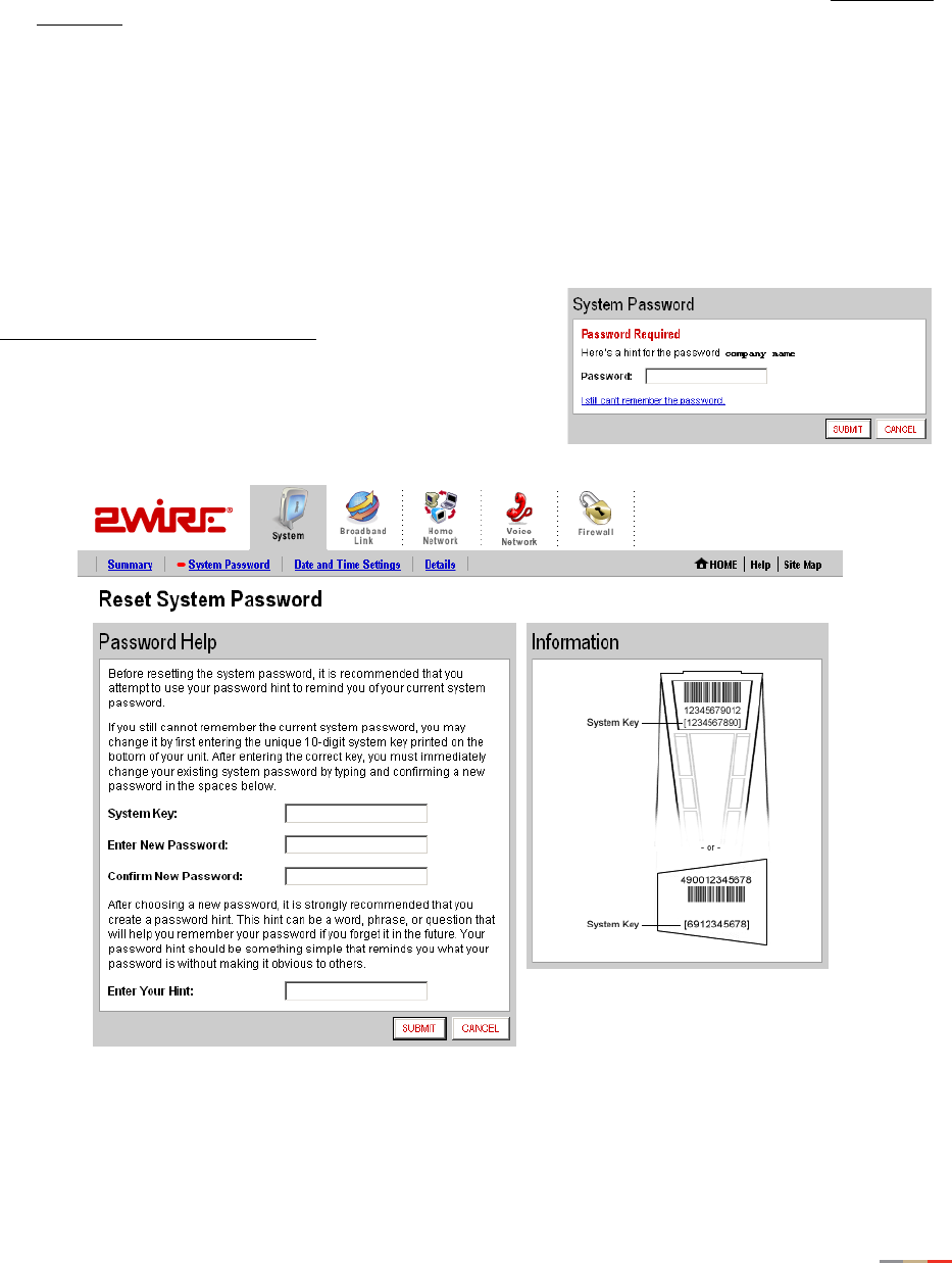
Resetting the System Password
If you forget your password and still cannot remember it
after seeing your hint, click the
I still can’t remember the password link.
The Reset System Password page opens.
Figure 4. Reset System Password Page
System Tab
8
To obtain access to your system:
1. In the System Key field enter the 10-digit system key located on the bottom of your gateway.
2. In the Enter New Password field, enter a new system password. In the Confirm New Password field, re-
enter the system password.
3. In the Enter Your Hint field, enter an appropriate hint as described under “Setting a System Password”
on page 6.
4. Click Submit.
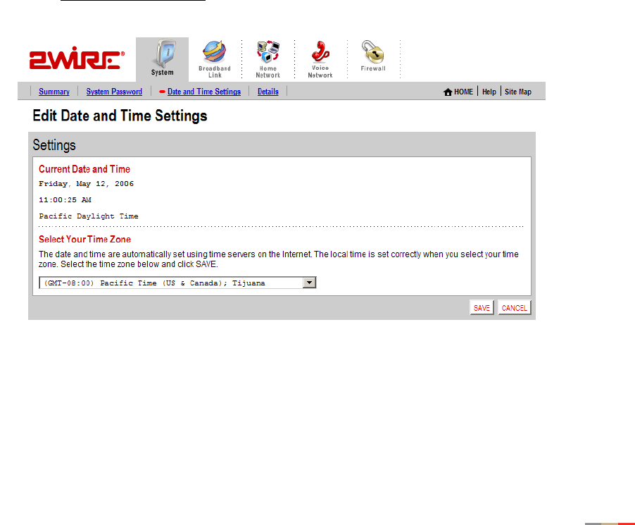
Changing Your Time Zone Settings
The 2Wire gateway sets the time automatically using time servers on the Internet. It retrieves date/time
information in Greenwich Mean Time (GMT). Your local time is set using the Time Zone setting you
configured when you set up your system. If your Time Zone is incorrectly set, you can change it in the Edit
Date and Time Settings page.
To change your time zone settings:
• Open a Web browser and access the gateway user interface by entering http://gateway.2wire.net.
• Click the System tab.
• Click the Date and Time Settings link in the System area of the Network at a Glance panel to open the
Edit Date and Time Settings page.
Figure 5. Edit Date and Time Settings Page
1. From the drop-down menu, select the time zone.
2. Click SAVE.
System Tab
9
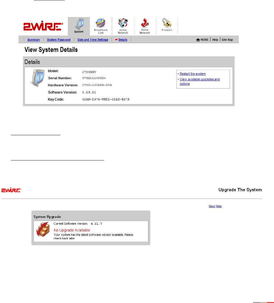
Viewing System Details
The System Details page provides information about your gateway, any enhanced services you may have,
and provides a link that you can use to restart your system.
To view the System Details page:
• Open a Web browser and access the gateway user interface by entering http://gateway.2wire.net.
• Click the System tab.
• Click the View details link in the System area of the Network at a Glance panel to open the View System
Details page.
Figure 6. View System Details Page
The Restart the system link restarts your system. Your network connections and your broadband
connectivity will be briefly disrupted until your system restarts and broadband connectivity is
re-established with your broadband service provider.
The View available upgrades and options link accesses a page that displays available software upgrades or
enhanced services. If your gateway is running the latest software or enhanced services are not available,
the following message displays.
10
Broadband Link Tab
This chapter describes the 2Wire gateway Broadband Link features, and provides detailed instructions on
how to customize your broadband settings.
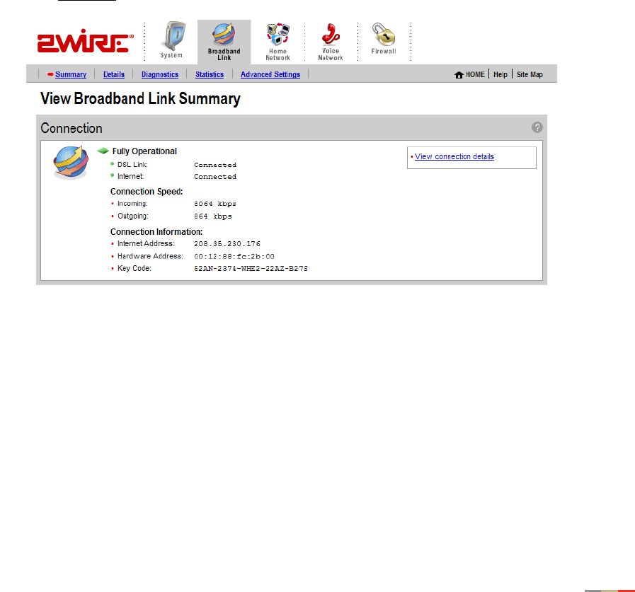
Viewing Your Broadband Link Summary
The Broadband Link Summary page provides general information about the current status of your
broadband link connection and your system configuration.
To access your Broadband Link Summary:
• Open a Web browser and access the gateway user interface by entering
http://gateway.2wire.net.
• Click the Broadband Link tab.
• Click the Summary link under the tab to open the View Broadband Link Summary page.
Figure 7. View Broadband Link Summary Page
The Connection panel shows information about your gateway’s connection to the Internet. The elements
displayed will vary, depending on your gateway model and the type of broadband service you have.
Connection Status
There are two ways you can check the current status of your gateway’s broadband connection: you can use
the DSL and Internet indicator lights on the front of your gateway, or, if your computer is connected to the
network, you can view the user interface.

Broadband Link Tab
11
Connection Speed
Connection Speed shows the incoming and outgoing data rates of your DSL connection, measured in
kilobits per second (Kbps). Incoming is the speed of data flowing from the Internet to your network;
Outgoing is the speed of data flowing from your network to the Internet.
Connection Information
Connection Information shows the following basic system configuration information:
•Internet Address. The broadband IP address assigned by your service provider to your gateway so that
it can communicate on the Internet. This address is assigned to you by your Internet Service Provider
for all communication on the Internet, and can either be Static (permanently assigned and manually
entered) or Dynamic (automatically assigned and configured), depending on your subscribed service
type.
•Hardware Address. (Also known as the MAC address, physical address or, if you are a cable customer,
the C number.) When your gateway is connected to the broadband network, an association is made
between its unique hardware address and its Internet address before it can communicate to the
Internet.
Note: This field displays the hardware address only if the gateway is connected to the Internet via PPPoE.
•Key Code. The activation code that tells your gateway how to connect to your service provider. The key
code is used during the installation process to customize the setup screens and settings for your
broadband provider.
Finding Your Hardware Address
If required to find your Hardware (MAC) address, refer to the following table and follow the instructions for
your operating system.
Windows OS Macintosh 8.x & 9.x Macintosh OS X
1. Click the Start menu.
2. Click Run.
3. Enter “cmd” in the
entry field.
4. Click OK.
5. At the C:\> prompt,
enter “ipconfig/all”.
6. Locate the Physical
address (for example,
01-24-H5-18-B3-00).
7. To close the window,
enter “exit” at the
C:\> prompt.
1. Click the Apple icon.
2. Select Control Panels.
3. Select TCP/IP.
4. From the Configure
pulldown menu, select
Built-in Ethernet.
5. From the File menu,
select Get Info. Your MAC
address appears as
either the Hardware
Address or the Ethernet
Address.
1. Click the Apple icon.
2. Select System
Preferences.
3. Click the Network icon.
4. Click the TCP/IP tab.
5. From the Configure
pulldown menu, select
Built-in Ethernet. Your
MAC address appears in
the lower-left corner as
the Ethernet Address.
Broadband Link Tab
12
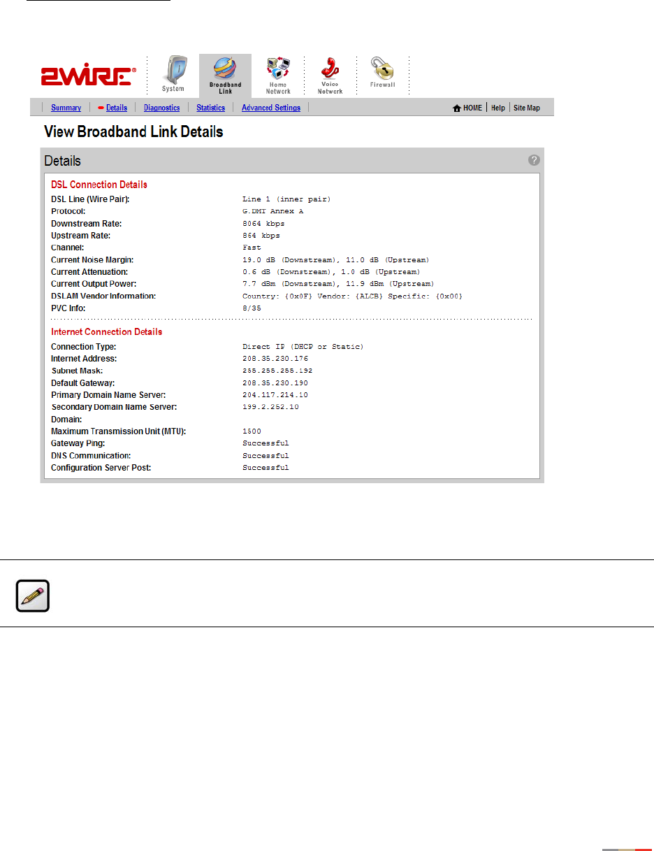
Connection Details
The View connection details link accesses the Broadband Link Details page, which displays technical
information about your broadband connection. Technical support representatives use this information to
help troubleshoot problems with your broadband connection.
Figure 8. View Broadband Link Details Page
The following table shows the information that may be displayed on the Broadband Link Details page.
Note: The information displayed depends on the type of broadband service you have and your
gateway model.

Broadband Link Tab
13
Item Description
DSL Connection
DSL Line (Wire Pair) The DSL signal can be transmitted on Line 1 (inner pair) or
Line 2 (outer pair). During installation, the gateway
automatically detects on which line the DSL signal is being
transmitted.
Protocol Displays which DSL protocol is being used to communicate
between your system and your service provider.
Downstream Rate The speed at which data comes over your broadband
connection from the Internet to your network, measured in
kilobits per second (kbps).
Upstream Rate The speed at which data goes over your broadband
connection from your network to the Internet, measured in
kilobits per second (kbps).
Channel The setting in this field is determined by your ISP’s DSLAM
equipment.
Current Noise Margin Indicates how much the noise on the DSL line can increase
before it begins to affect the DSL signal. As the noise on the
DSL line increases, the margin will approach zero. If the noise
exceeds the current noise margin, the DSL signal will be lost.
The level is measured in decibels (dBs).
Current Attenuation Represents the decrease in signal strength between
origination of the DSL (Central Office) and your gateway.
Customers who live close to their Central Office usually will
have less signal loss and a low current attenuation. The level
is measured in decibels (dBs).
Current Output Power The current DSL transmit power of your gateway. The level is
measured in decibels (dBs).
DSLAM Vendor Information A DSLAM is the piece of equipment located in the Central
Office (CO) that provides the DSL signal to your DSL line. The
Vendor Information identifies information about the
configuration of this equipment.
PVC Info Displays the pair of numbers that uniquely identifies the ATM
virtual circuit between the system and the provider of your
DSL service.
Internet Connection Details
Connection Type Identifies the method by which the gateway connects to the
Internet Service Provider (ISP): PPPoE, PPPoA, or Direct.

Broadband Link Tab
14
Username The name used to connect with your Internet Service Provider
(ISP). Your username was either assigned to you or configured
by you during the install process. The correct username is
required to successfully connect to the Internet.
Internet Address A number that is assigned to a computer so that it can
communicate on a network and on the Internet. This address
is assigned to you by your Internet Service Provider for all
communication on the Internet, and can be either Static
(permanently assigned and manually entered) or Dynamic
(automatically assigned and configured).
The typical configuration is for your ISP to automatically
assign and configure an Internet address (Dynamic) when your
system connects to the Internet.
Businesses or power users may use a static address enabling
them to run advanced services such as Internet servers and
video conferencing. Static addresses typically cost more
because they must be leased from the ISP.
If you receive your Internet address settings automatically, the
subnet mask has been set for you. If you manually set your
Internet address (Static IP), this is the information that was
provided to you by your ISP and entered by you during gateway
installation.
Subnet Mask Part of the Internet address settings and used in conjunction
with your Internet address. If you receive your Internet
address settings automatically, the subnet mask has been
set for you. If you manually set your Internet address (Static
IP), this is the information that was provided to you by your ISP
and entered by you during gateway installation.
Default Gateway Part of the Internet address settings. The default gateway is a
device your 2Wire gateway communicates with directly to give
you access to the Internet.
If you receive your Internet address settings automatically, the
subnet mask has been set for you. If you manually set your
Internet address (Static IP), this is the information that was
provided to you by your ISP and entered by you during the
system installation.
Item Description

Broadband Link Tab
15
Primary Domain Name Server Part of the Internet address settings. A domain name is a
meaningful, easy-to-remember “handle” for an Internet
address. The DNS allows Internet users to specify a name
(domain name) to reach a Web page (for example,
www.domainname.com) instead of its Internet address (for
example, 111.222.111.222). When you enter the name of a
Web location (URL), the DNS looks up the name and resolves
it to the Web page’s Internet address.
If you receive your Internet address settings automatically, the
subnet mask has been set for you. If you manually set your
Internet address (static IP), this is the information that was
provided to you by your ISP and entered by you during gateway
installation.
Secondary Domain Name
Server
Used as a backup if the Primary server fails to respond.
If you receive your Internet address settings automatically, the
subnet mask has been set for you. If you manually set your
Internet address (Static IP), this is the information that was
provided to you by your ISP and entered by you during the
system installation. This parameter may not be necessary and
may be left blank.
Domain The name that associates your gateway with your ISP on the
broadband link. This parameter may not be necessary and
may be left blank.
If you receive your Internet address settings automatically, the
subnet mask has been set for you. If you manually set your
Internet address (Static IP), this is the information that was
provided to you by your ISP and entered by you during gateway
installation.
Maximum Transmission Unit
(MTU)
Shows the maximum size allowed on packets that are sent to
and from your network to your ISP.
Gateway Ping The 2Wire gateway periodically checks the connection
between itself and your ISP’s Default Gateway. This field
informs you that the check has been performed and whether
or not it was successful.
DNS Communication The gateway periodically checks the connection between itself
and your ISP’s domain name server(s) to make sure DNS is
available. This field informs you that the check has been
performed and whether or not it was successful.
Configuration Server Post The gateway periodically checks the connection between itself
and the 2Wire Component Management System. This field
informs you that the check has been performed and whether
or not it was successful.
Item Description

Broadband Link Tab
16
Monitor Internet Connection
The Monitor Internet connection link launches the Speed Meter. The Speed Meter measures the actual rate
at which data is coming into (Incoming Kbps) and going out of (Outgoing Kbps) your system. It measures
real-time data throughput in Kilobits per second and displays in one-second intervals.
The Speed Meter monitors the actual data rates while connecting to a Web site. This data rate can differ
from the reported speed of your broadband connection due to many factors, including traffic to the Web site
or the speed of the Web servers at the site you are visiting.
Test Connection Speed
The Test connection speed link launches the 2Wire Bandwidth Meter. The Bandwidth Meter measures the
maximum download speed from 2Wire’s Web site to your system in Kilobits per second (Kbps).
The 2Wire Bandwidth Meter estimates your connection speed from the Internet. Because the Internet
consists of thousands of interconnections, your connection to a Web site could be affected by many
different factors. If you experience slow performance on a particular Web site, you can use the 2Wire
Bandwidth Meter to verify whether this is isolated to that particular Web site, or if it is a more general
occurrence. Because the 2Wire Bandwidth Meter measures the download speed from 2Wire’s Web site to
your computer and can be affected by many factors on the Internet, it is not an accurate measurement of
the service from your ISP.
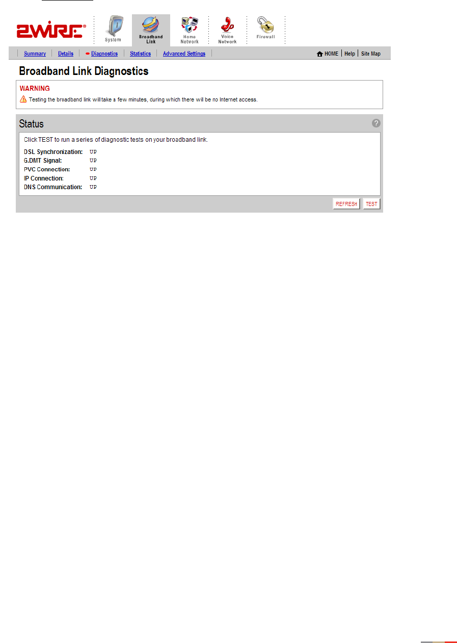
Using Broadband Diagnostics
Diagnostics displays an itemized list of your broadband connection’s current status. Technical support
representatives use this information to help troubleshoot problems with your broadband connection.
To access the Broadband Link Diagnostics page:
• Open a Web browser and access the gateway user interface by entering
http://gateway.2wire.net.
• Click the Broadband Link tab.
Note: To use the Speed Meter, your browser must support Java 2.
Broadband Link Tab
17
• Click the Diagnostics link under the tab to open the Broadband Link Diagnostics page.
Figure 9. Broadband Link Diagnostics Page
To update the broadband link status, click REFESH.
To initiate a full test of your broadband link, click TEST. The test will take several minutes, during which the
system reestablishes all broadband connections. You will not be able to access the Internet until the test is
complete.
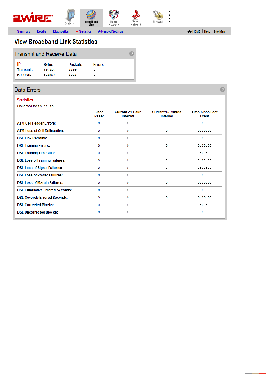
Viewing Statistics
The View Broadband Link Statistics page shows statistics associated with the 2Wire gateway broadband
link, including cumulative DSL statistics.
To access the Broadband Link Statistics page:
• Open a Web browser and access the gateway user interface by entering
http://gateway.2wire.net.
• Click the Broadband Link tab.
Broadband Link Tab
18
• Click the Statistics link under the tab to open the View Broadband Link Statistics page.
Figure 10. View Broadband Link Statistics Page
The Transmit and Receive Data panel displays the following information.
•Transmit. The cumulative number of IP packets transmitted, the cumulative number of IP payload bytes
transmitted, and the number and percentage transmitted in error.
•Receive. The number of bytes and packets received, and the number and percentage received in error.

Broadband Link Tab
19
The Data Errors panel displays the following information.
Data Error Description
ATM Cell Header Errors The number of ATM cell header CRC errors since the 2Wire gateway
was last restarted, and the elapsed time since the last cell header
error.
ATM Loss of Cell Delineation The number of ATM loss of cell delineation errors since the 2Wire
gateway was last restarted, and the elapsed time since the last
loss of cell delineation error.
DSL Link Retrains The number of DSL retrains since the 2Wire gateway was last
restarted, and the time elapsed since the last retrain.
DSL Training Errors The number of failed DSL retrains since the 2Wire gateway was
last restarted, and the elapsed time since the last failed retrain.
DSL Training Timeouts The number of timeouts waiting for response from ATU-C since the
2Wire gateway was last restarted, and the elapsed time since the
last initialization timeout.
DSL Loss of Framing Failures The number of DSL loss of framing failures since the 2Wire
gateway was last restarted, and the elapsed time since the last
line search initialization.
DSL Loss of Signal Failures The number of DSL loss of signal failures since the 2Wire gateway
was last restarted, and the elapsed time since the last loss of
signal failure.
DSL Loss of Power Failures The number of DSL loss of power indications from the ATU-C since
the 2Wire gateway was last restarted, and the elapsed time since
the last loss of power indication.
DSL Loss of Margin Failures The number of DSL loss-of-margin failures at current data rate
since the 2Wire gateway was last restarted, and the elapsed time
since the last loss of margin failure.
DSL Cumulative Errored
Seconds
The number of cumulative errored seconds since the 2Wire
gateway was last restarted, and the elapsed time since the last
error.
DSL Severely Errored Seconds The number of severely errored seconds since the 2Wire gateway
was last restarted, and the elapsed time since the last severely
errored second.
DSL Corrected Blocks The number of corrected DSL superframes that had data errors
detected during reception.

Broadband Link Tab
20
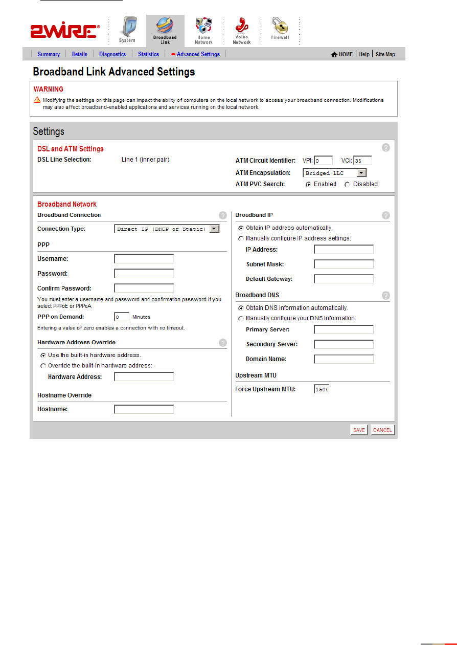
Using Advanced Settings
The Advanced Settings page allows you to manually configure your DSL and Internet connection settings.
Typically, these settings are automatically provided by your service provider. You should adjust these
settings ONLY if you are very familiar with DSL and networking technology.
To access the Broadband Link Advanced Settings page:
• Open a Web browser and access the gateway user interface by entering
http://gateway.2wire.net.
• Click the Broadband Link tab.
DSL Uncorrected Blocks The number of uncorrected DSL superframes that had data errors
detected.
ISP Connection Establishment The number of times the ISP connection was established since the
statistics were last reset, and the elapsed time since the last
establishment.
Data Error Description
Broadband Link Tab
21
• Click the Advanced Settings link under the tab to open the Broadband Link Advanced Settings page.
Figure 11. Broadband Link Advanced Settings Page
Modifying DSL and ATM Settings
By default, the gateway automatically detects which DSL line to use. The DSL and ATM panel allows you to
select a DSL line and manually configure your ATM settings.
1. From the DSL Line Selection drop-down menu, select Automatic, Line 1 (inner pair), or Line 2 (outer
pair).
2. In the ATM Circuit Identifier VPI and VCI fields, enter the VPI and VCI you want the gateway to use to
connect to your ISP.

Broadband Link Tab
22
3. From the ATM Encapsulation drop-down menu, select Bridged LLC, Bridged VC-Mux, Routed LLC, or
Routed VC-Mux.
4. In the ATM/PVC Search field, click the Enabled or Disabled radio button.
5. Click SAVE.
Modifying Broadband Connection Settings
The Broadband Connection panel allows you to modify your broadband connection.
1. From the Connection Type drop-down menu, select the connection type: PPPoE, PPPoA, Direct IP (DHCP
or Static), or Routed IPoA.
If you connect via PPPoE or PPPoA, proceed to step 2. If you connect via Direct IP or Routed IPoA,
proceed to step 5. Direct IP and Routed IPoA connections do not require a user name or password.
2. In the Username field, enter your user name.
3. In the Password field, enter your password.
4. In the Confirm Password field, re-enter your password.
5. In the PPP on Demand field, enter a value for the length of time you wish the PPP session to remain
active.
If the value is set to 0, the PPP session will not time-out (it will be always-on). If the value is between 1
to 10080 minutes, the PPP session will time-out if the gateway doesn’t detect outbound traffic destined
for the Internet in the specified time.
6. Click SAVE.
Modifying the Hardware Address
By default, the gateway uses its built-in hardware address. The Hardware Address Override panel allows you
to manually override the MAC address of the broadband connection, which is sometimes required for cable
modems that perform MAC address authentication.
1. Click the Override the built-in hardware address radio button.
2. In the Hardware Address field, enter the alternative hardware address.
3. Click SAVE.
Enabling Hostname Override
In the DHCP Host Name field, enter the DHCP host name you want the gateway to use. This field is only
relevant if your ISP uses DHCP host name authentication.

Broadband Link Tab
23
Modifying the Broadband IP
By default, the gateway automatically obtains its Internet address. The Broadband IP panel allows you to
manually configure your Internet address settings.
1. Click the Manually configure IP address settings radio button.
2. In the IP address field, enter the IP address you want the gateway to use.
3. In the Subnet Mask field, enter the subnet mask you want the gateway to use.
4. In the Default Gateway field, enter the default gateway address you want the gateway to use.
5. Click SAVE.
Modifying the Broadband DNS
By default, the gateway automatically obtains the DNS server addresses via DHCP. The Broadband DNS
panel allows you to manually configure your DNS information.
1. Click the Manually configure your DNS information radio button.
2. In the Primary Server field, enter the IP address of the primary DNS server that the gateway is to use for
DNS name resolution.
3. In the Secondary Server field, enter the IP address of the secondary DNS server that the gateway is to
use for DNS name resolution.
4. In the Domain Name field, enter the specific domain name to be used by the gateway.
5. Click SAVE.
Note: If you choose to manually configure your system and have a problem, re-run your
installation and follow the installation instructions provided to you by your service provider.
24
Home Network Tab
This chapter describes the 2Wire gateway Home Network features, and provides detailed instructions on
how to customize your network settings.
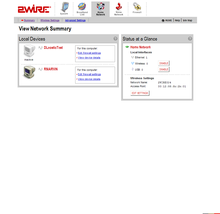
Viewing Your Home Network Summary
The Home Network Summary page displays information about the devices installed on your network.
To access the Home Network Summary page:
• Open a Web browser and access the 2Wire gateway user interface by entering
http://gateway.2wire.net.
• Click the Home Network tab to open the View Network Summary page.
Figure 12. View Network Summary Page
Understanding the Local Devices Panel
The Local Devices panel shows you the name of the device, how it is connected, any special configuration
information, and provides links to other system features that you can set up for the device. A “device” on
your network is usually a computer — either a personal computer used by a household member, or a
computer that is dedicated to a specific use (such as a Web server that hosts online games). The status of
each device is shown in the Local Devices list in your 2Wire gateway user interface.
Home Network Tab
25
Each device on your home network is represented with a computer icon.
If the “show inactive devices” option is enabled, and the device becomes inactive
because it is powered off or removed from your network, this icon will display as Inactive.
A symbol next to the device shows how it is connected to your home network:
If you defined a name for your computer during System Setup or when your computer was set up, the name
displays next to the device. However, there are two instances where the device name will not appear:
• If your computer was manually configured with a static IP address, the static IP address displays
instead of the computer’s name.
• If you have not named the device but it still obtains its Internet address from the system, the word
“Unknown” displays.
You can change the name of the device so that it will display in the system user interface by clicking the
Change name link.
If you have configured the firewall to allow information from the Internet to pass through to the computer
(also referred to as “hosting an application”), the name of the application(s) that you are hosting are
displayed under the device name.
If you have defined special features for the computer (such as DMZplus mode), the feature is displayed
under the device name.
Note: For additional information, refer to “Showing a Device as Inactive” on page 33.
Ethernet USB Wireless
Note: For additional information, refer to “Hosting an Application” on page 41.
Home Network Tab
26
Depending on the permissions you have set for devices on your network, the following links may display
next to the device:
• Access shared files. Accesses the shared files available from this computer. This feature only works
with Microsoft Windows computers that have shared files and file sharing installed.
Note: If your computer is configured with a static IP address, this link will not appear.
• Edit firewall settings. Accesses the system user interface page, which allows you to edit the firewall
pass-through settings for the computer. For example, you may need to change the pass-through settings
for the computer if you want to play an Internet game.
• View Internet Access Control. Accesses the Internet Access Restriction schedule for this computer.
• Edit Content Screening. Accesses the Content Screening settings page, allowing you to change the Web
site permissions for users on your network.
• View device details. Displays the technical networking details about the device. If you are experiencing
difficulties, this information may be helpful to a technical support representative.
Understanding the Status at a Glance Panel
The Status at a Glance panel shows you a list of network
connection types, the number of devices connected via each
connection type, and your wireless settings.
To change your wireless settings, click the EDIT SETTINGS button.
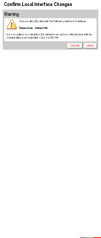
To disable a network device, click the DISABLE button.
A message asks you to confirm your decision.
Monitoring Your Wireless Settings
Your 2Wire gateway has an integrated wireless access point, which enables you to connect your wireless-
enabled computers to your home network.
By default, the 2Wire gateway ships with WEP enabled and a preconfigured network name. The default WEP
key is located on the bottom of the gateway, next to the serial number.
To check your current settings and configure changes:
• Open a Web browser and access the 2Wire gateway user interface by entering
http://gateway.2wire.net.
• Click the Home Network tab.
Home Network Tab
27
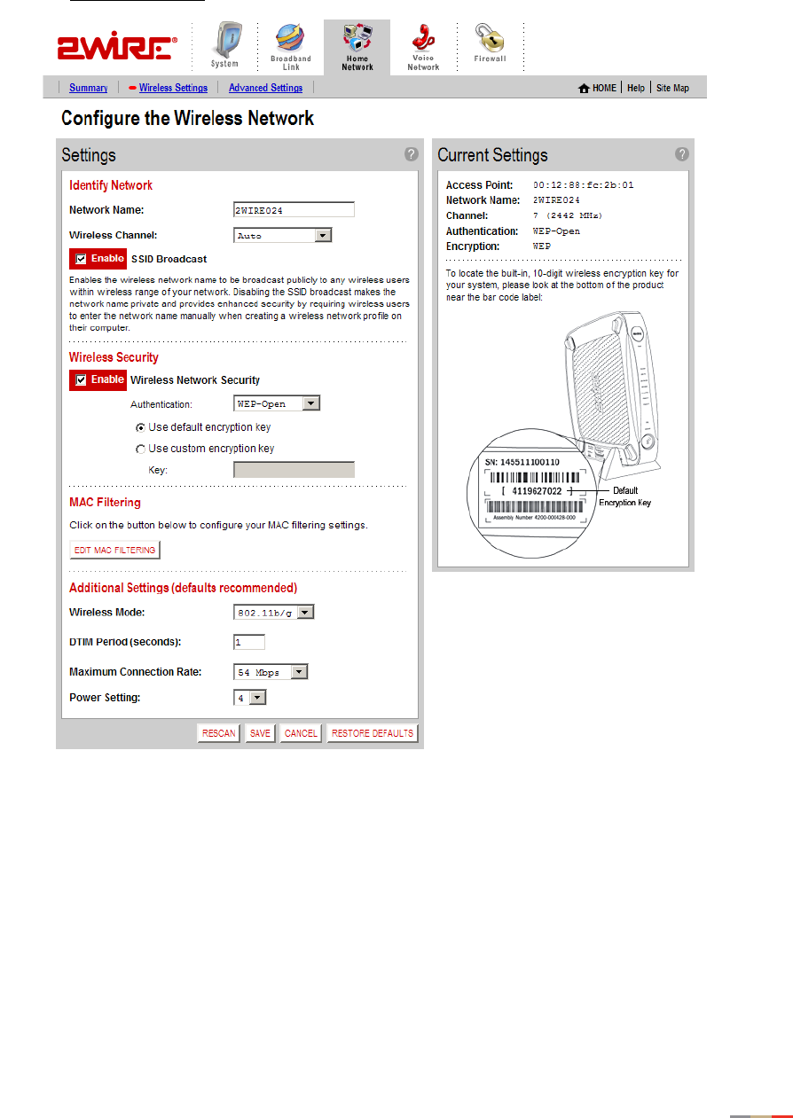
• Click the Wireless Settings link to open the Configure the Wireless Network page.
Figure 13. Configure the Wireless Network Page

Home Network Tab
28
The Current Settings panel shows the 2Wire gateway’s wireless access point settings:
•Access Point. The designated name of the wireless access point.
•Network Name. The name assigned to your wireless network. The default is 2WIREXXX, where XXX
represents the last three digits of your 2Wire gateway serial number (for example, 2WIRE954).
•Channel. The radio frequency band the access point uses for your wireless network (the default is 6).
Wireless adapter cards auto-detect which channels to use. If you are having problems with your
wireless network, it could be due to radio interference. You can change the wireless channel to see if
interference is reduced on a different channel.
Note: For more information on wireless channels, refer to the wireless channel entry on page 132 in the
Glossary.
•Authentication. The security method used to ensure that users are authorized to access the wireless
network: WEP-Open, WEP-Shared, or WPA-PSK.
•Encryption. The security setting that makes it difficult for unauthorized users to access your network.
Customizing Security Settings
You should always enable encryption for wireless communication. When encryption is enabled, you must
define an encryption key for the 2Wire gateway’s wireless access point and configure that same key on each
wireless client that will use your 2Wire gateway wireless network.
You can customize the following wireless settings in the Wireless Security panel.
1. From the Authentication pull-down menu, select an authentication setting: WEP-Open, WEP-Shared, or
WPA-PSK.
Note: WPA-PSK authentication is supported only on HG model gateways.
Open authentication allows users to configure their wireless adapter as either Open or Shared; in either
case an encryption key is required. Shared authentication allows users to configure their wireless
adapter for Shared authentication, which requires an encryption key. WPA-PSK requires that users
configure their wireless adapter using TKIP.
2. To use the encryption key that came with your gateway, click the Use default encryption key radio button.
To create a custom encryption key, click the Use custom encryption key radio button.
If you select Use custom encryption key, you can define a 64-bit or 128-bit encryption key. For 64-bit
encryption, enter a 10-digit hexadecimal number. For 128-bit encryption, enter a 26-digit hexadecimal
number. A hexadecimal number uses the characters 0-9, a-f, or A-F.
3. Click SAVE.
Note: If encryption is enabled, each wireless client must be configured with the encryption key
defined on the system before it can operate on your wireless network.
Home Network Tab
29
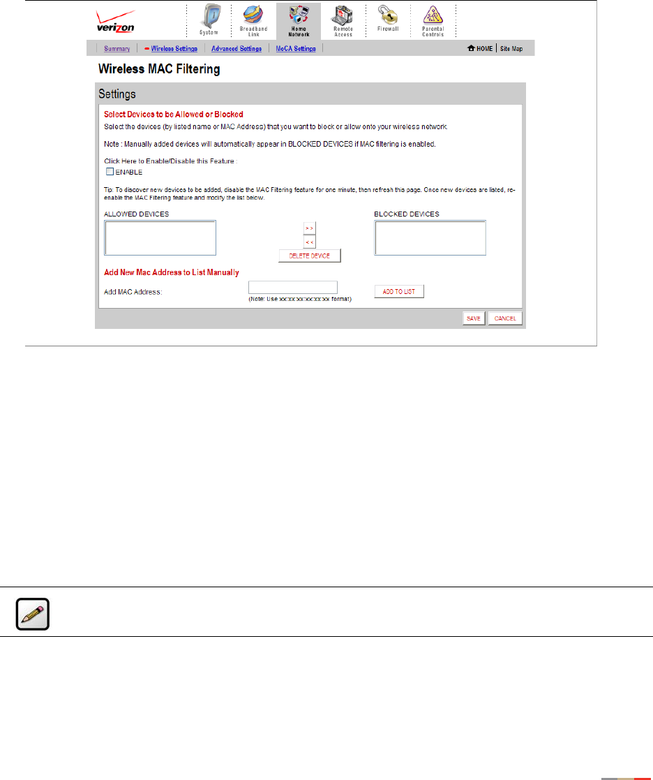
Configuring MAC Filtering
The Media Access Control (MAC) address is a unique number assigned to computer hardware. When setting
up your network, you can set your Wireless Broadband Router to give access only to certain MAC
addresses. By doing so, you limit access only to your computer hardware and no one else's.
1. In the MAC Filtering pane, click the EDIT MAC FILTERING button. The Wireless MAC Filtering page opens.
2. Click the Enable checkbox.
3. The MAC addresses of devices on your network appear in the ALLOWED DEVICES field. To block specific
devices from accessing your network, highlight the device’s MAC address (or name) and use the arrows
to move the address to the BLOCKED DEVICES field.
4. Click SAVE.
Configuring Additional Settings
The Additional Settings panel allows you to customize wireless settings. In general, it is recommended that
you leave the default settings in place; however, if you are experiencing connection or performance
difficulties, altering these settings may improve performance.
•Wireless Mode. Allows you to force the gateway to use 802.11b/g, 802.11b-only, or 802.11g-only
modes of operation.
Note: This field displays only for 802.11b/g based models.
Note: Because the fields that display are dependent on the type of wireless adapter you are
using, some of these settings may not display.

Home Network Tab
30
•DTIM Period (seconds). Determines at which interval the access point will send its broadcast traffic.
The default value is 4 seconds.
•Maximum Connection Rate. The maximum rate at which your wireless connection works (1, 2, 5.5, 11,
or 22 Mbps for 802.11b-based models; 1, 2, 5.5, 11, 6, 9, 12, 24, 36, 48, or 54 Mbps for 802.11b/
g-based models).
•Power Setting. Allows you to select the power level for your wireless connection. The default list is 1 to
4; additional options may appear based on the service provider’s configuration.
If you have customized your wireless system configuration, you can restore the wireless settings to factory
defaults by clicking the RESTORE DEFAULTS button.
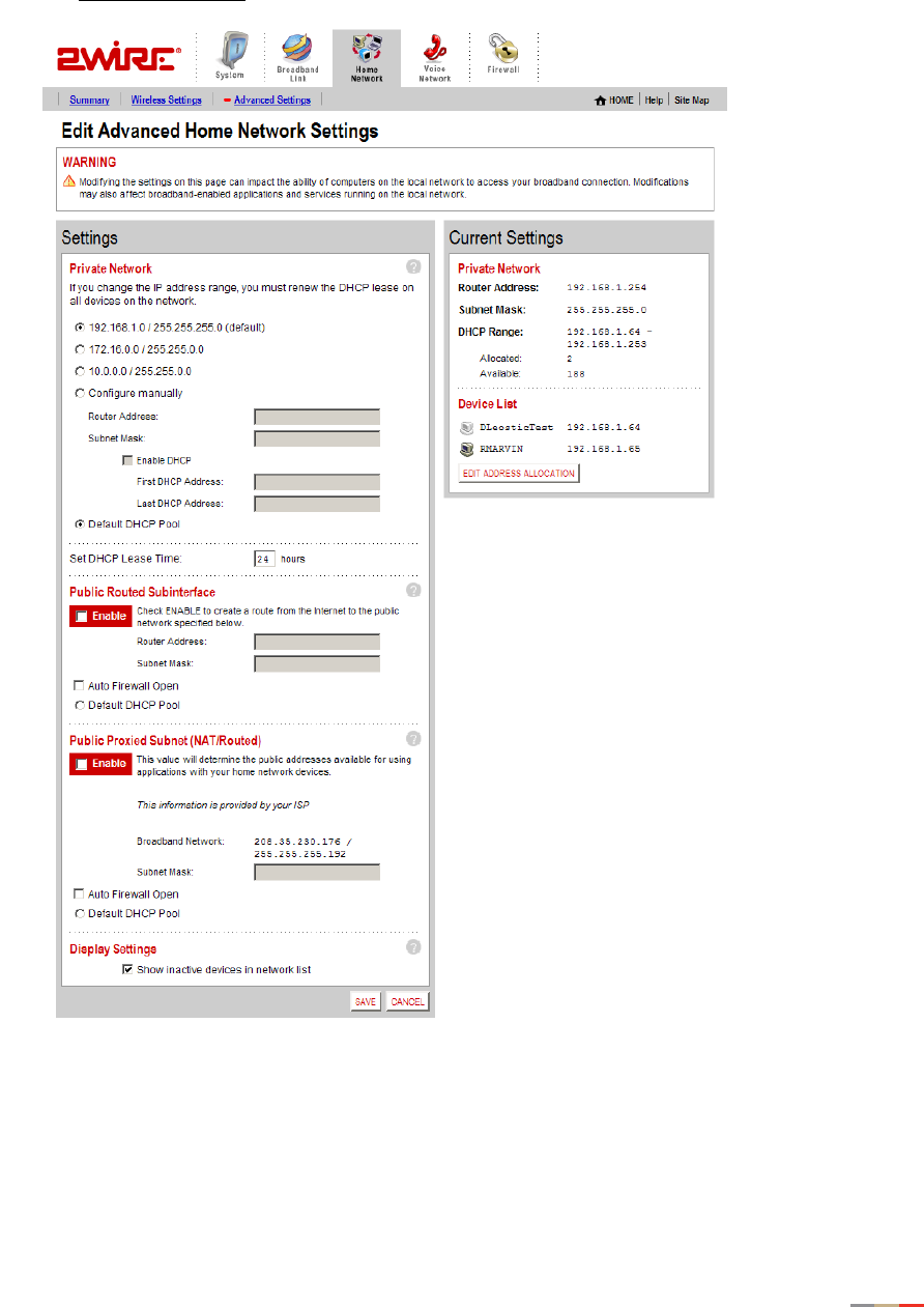
Configuring Advanced Settings
The Edit Advanced Home Network Settings page displays the current IP settings in use by your system for
your home network, and allows you to configure your home network settings. You should adjust these
settings ONLY if you are very familiar with computer networking technologies.
The Current Settings panel shows the following information:
•Router Address. The IP address used by your system on the private home network (the default is
192.168.0.1). The system has two IP addresses: a private address that it uses on the home network,
and one that is used on the public broadband connection on the Internet. You can change the home
network IP address by changing the home network IP address range.
•Subnet Mask. The subnet mask is determined by the home network IP address range settings (the
default is 255.255.0.0).
•DHCP Range. The range of IP addresses used by your system (the default is 192.16.1.33 through
192.16.1.250). IP addresses can be either static (permanently assigned) or dynamic (automatic and
temporary).
Setting up a Private Network
By default, the 2Wire gateway uses the 192.168.1.0/255.255.0.0 IP address range. You can select from
two additional IP address ranges, or configure the network settings manually. You should manually configure
these settings ONLY if you thoroughly understand IP internetworking, because an incorrect configuration can
cause unpredictable results.
To set up a private network:
• Open a Web browser and access the 2Wire gateway user interface by entering
http://gateway.2wire.net.
• Click the Home Network tab.
Home Network Tab
31
• Click the Advanced Settings link under the tab to open the Edit Advanced Home Network Settings page.
Figure 14. Advanced Home Network Settings Page

Home Network Tab
32
1. Click the radio button that corresponds to the IP address range you wish to use.
If you select the 172.16.0.0 / 255.255.0.0 or 10.0.0.0 / 255.255.0.0 range, continue to step 5. If
you select Configure manually, continue to step 2.
2. In the Router Address field, enter the IP address used by your system on the private home network.
3. In the Subnet Mask field, enter the subnet mask. The subnet mask is determined by the home network
IP address range settings.
4. Click the Enable DHCP checkbox.
a. In the First DHCP Address field, enter the first DHCP address that you’ll be distributing over the
private network.
b. In the Last DHCP Address field, enter the last DHCP address that you’ll be distributing over the
private network.
c. In the Set DHCP Lease Time field, enter a value for the number of hours before the DHCP lease
expires.
5. Click SAVE.
Setting Up a Public Routed Subinterface
The Public Routed Subinterface pane allows you to create a local network that has broadband network-
accessible IP addresses by creating a route from the Internet to the specified public network. The public
network operates without Network Address Translation (NAT). This feature is typically used in conjunction
with broadband service that provides a range of available IP addresses. Once enabled, the public IP
addresses can be assigned to local computers.
To set up a Public Routed Subinterface network:
1. Check the Enable checkbox.
2. In the Router Address field, enter the router address (this is typically provided by your service provider).
3. In the Subnet Mask field, enter the subnet mask (this is typically provided by your service provider).
4. (Optional) To open all firewall ports, check the Auto Firewall Open checkbox. (By default, your firewall
protection is enabled.)
5. Click SAVE.
Note: If you change the home network IP address range, you must renew the DHCP lease on
all devices on your home network and manually reconfigure all devices configured with static IP
addresses. If you are using the 2Wire Network Support Tool, you can renew the DHCP lease by
selecting “Refresh Network Connection” in the Network Support Tool menu.

Home Network Tab
33
Setting Up a Public Proxied Subnet
The Public Proxied Subnet pane allows you to create a local network that has broadband-accessible IP
addresses. Public Proxied Subnet is a public network in which the local network is an extension of the
broadband network and does not require any special routing. Computers that are assigned Public Proxied
Subnet IP addresses operate without Network Address Translation (NAT). This feature is typically used in
conjunction with broadband service that provides a range of IP addresses. Once enabled, the Public Proxied
Subnet IP addresses can be assigned to local computers.
To set up a public proxied subnet:
1. Check the Enable checkbox.
2. In the Subnet Mask field, enter the subnet mask (this is typically provided by your service provider, and
defines how large your IP pool is).
3. (Optional) To open all firewall ports, check the Auto Firewall Open checkbox. (By default, your firewall
protection is enabled.)
4. Click SAVE.
Selecting a Default DHCP Pool
By default, all devices on the home network that use dynamic (non-static) IP addresses receive these from
the Private Network DHCP pool. When either Public Routed Subinterface or Public Proxied Subnet is
enabled, click the Default DHCP Pool radio button in the corresponding section to have devices receive their
IP addresses from those pools.
Showing a Device as Inactive
To show a device as Inactive:
1. Open a Web browser and access the 2Wire gateway user interface.
2. Click the Home Network tab.
3. Click the Advanced Settings link under the tab.
4. In the Settings pane, select the Show inactive devices in network list checkbox.
5. Click SAVE.
34
VoIP Network Tab
This chapter describes the 2Wire gateway VoIP Network features, and provides detailed instructions on
setting up a VoIP network.
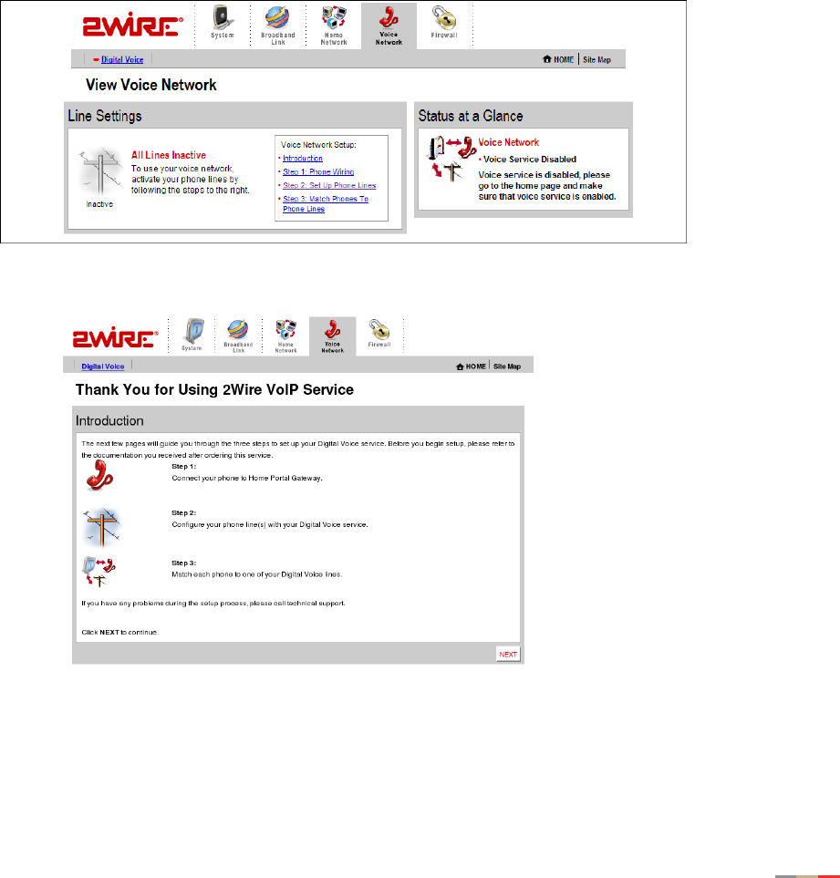
Configuring the VoIP Phones
To configure VoIP via the gateway user interface, follow these steps.
1. Access the gateway user interface by opening a web browser and entering http://gateway.2wire.net.
Click the Voice Network tab. The View Voice Network page opens
2. In the Voice Network Setup box, click Introduction. The Introduction page displays.
VoIP Network Tab
35
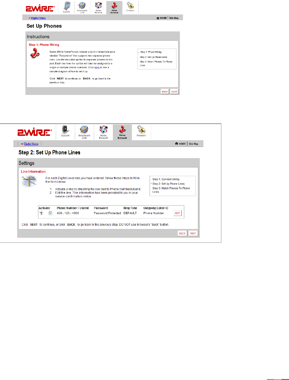
3. Click NEXT to continue. The Set Up Phones (Step 1: Phone Wiring) page displays. Follow the on-screen
instructions.
4. Click NEXT. The Step 2: Set Up Phone Lines page opens. Activate a line by checking the box next to
Phone Number/Userid. Click EDIT to change the settings.
5. The account is based on username or phone number. To change this setting, enter a Username or
phone number in the User Name box. From the Ring Tone pull-down menu, select the tone you wish to
associate with the phone (and click LISTEN to hear the selected ring tone). To block the outgoing caller
ID, click the Anonymous checkbox. To ensure that the settings cannot be changed, enter a username
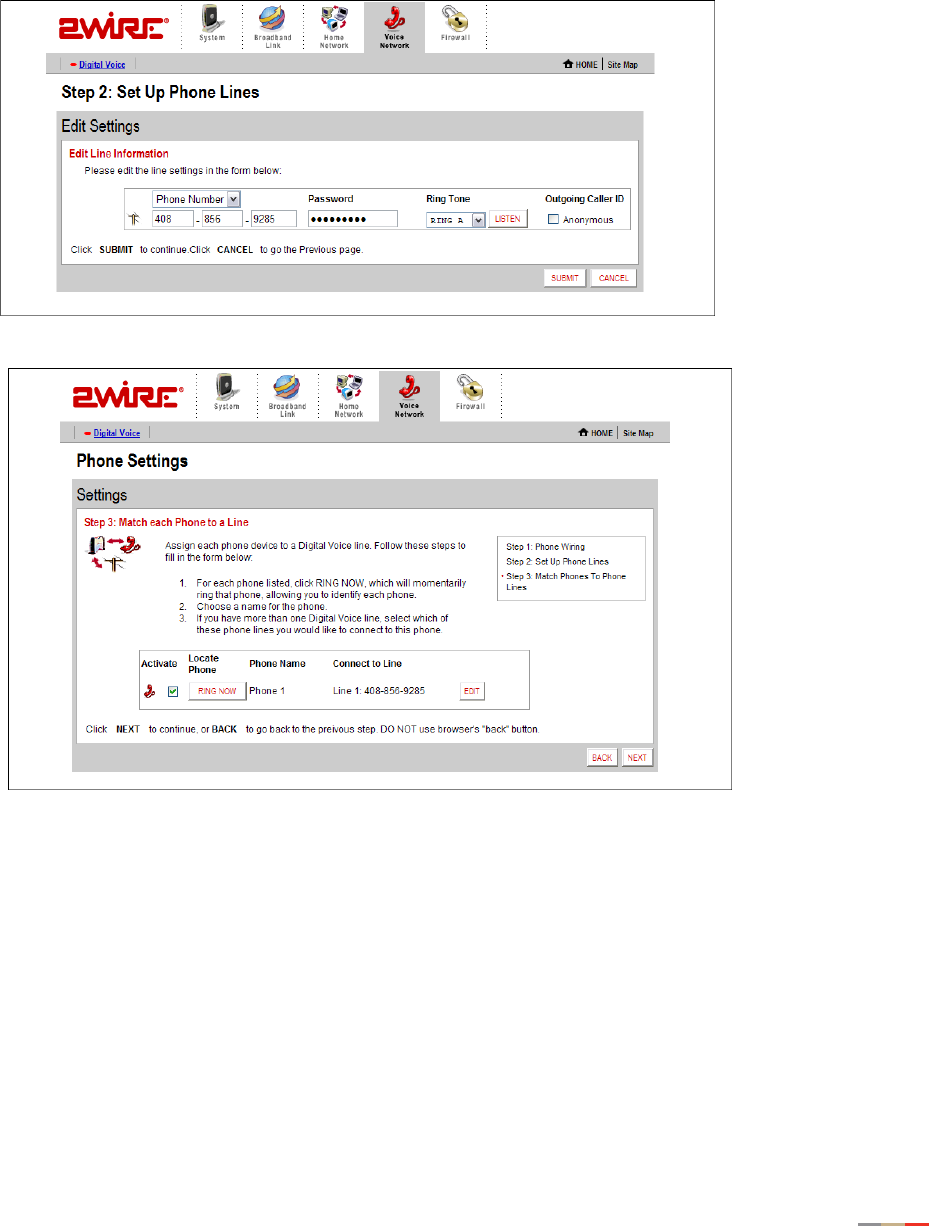
VoIP Network Tab
36
and password in the Auth Username and Auth Password boxes under the Credentials subheading. Click
SUBMIT to continue. Next, the Phone Settings page opens.
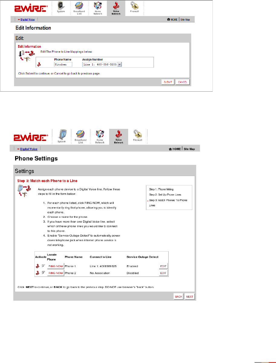
6. The Phone Settings page allows you to match each telephone to a phone line.To do so, click EDIT.
VoIP Network Tab
37
7. In the Phone Name field, select a name to associate with the phone. If you have more than one digital
voice line, in the Assign Number field select the phone line you wish to associate with this phone. Click
SUBMIT to continue. The Phone Settings (Step 3: Match each Phone to a Line) page displays.
8. Check the box next to each phone line to activate it. To identify and locate each phone listed, click RING
NOW, which will momentarily ring that telephone. Click EDIT to edit phone name, line connection
association, and whether to enable service outage detection. Click NEXT to continue.
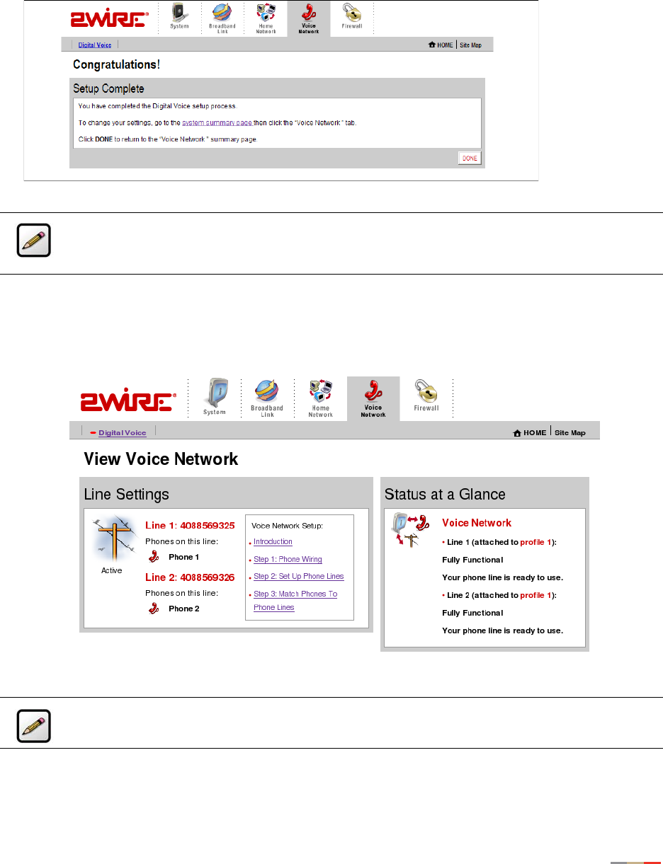
VoIP Network Tab
38
9. Congratulations, setup is complete. Click DONE to return to the Voice Network summary page. If you
want to change your settings, go to the System Summary page, then click the Voice Network tab.
Once the VoIP server configuration settings have been implemented, open a browser and enter http://
gateway.2wire.net. Click the Voice Network tab. The View Voice Network page displays. You can view the
status of your VoIP line(s) in the Status at a Glance section.
Note: To make any broadband connection settings changes, such as configuring the voice
servers, refer to the Management and Diagnostic Console. See “Management and
Diagnostic Console” on page 58.
Note: To comply with Australian standards, local ports shall not be connected via shared
building cabling.

39
Firewall Tab
This chapter describes the 2Wire gateway firewall features, and provides detailed instructions on how to
modify the firewall settings.
Firewall Features
The 2Wire gateway has a professional-grade firewall to help prevent unauthorized users from accessing
your local network. The 2Wire gateway firewall includes the following features:
Stateful packet inspection. Blocks common Denial of Service attacks (such as SYN/FIN flooding or Smurf),
and detects and logs TCP and UDP port scans.
Stateless packet inspection. Filters specific NetBios traffic, suspicious packets and IP fragments; blocks
packets sent from the private network to the Internet that have spoofed IP addresses.
Network Address Translation (NAT). Translates a local network’s IP address to an external address
maintained by the 2Wire gateway, effectively “hiding” the existence of a home network to the Internet. The
2Wire gateway then uses this external address to communicate with the Internet on behalf of devices
connected to the local network.
Port Address Translation (PAT). A function provided by some routers which allows hosts on a LAN to
communicate with the rest of a network (such as the Internet) without revealing their own private IP
address. All outbound packets have their IP address translated to the router’s external IP address. Replies
come back to the router, which then translates them back into the private IP address of the original host for
final delivery. During PAT, each computer on the LAN is translated to the same IP address, but with a
different port number assignment.
Inbound and outbound port blocking. Blocks common inbound and outbound protocol types from passing
information to or receiving information from the Internet.
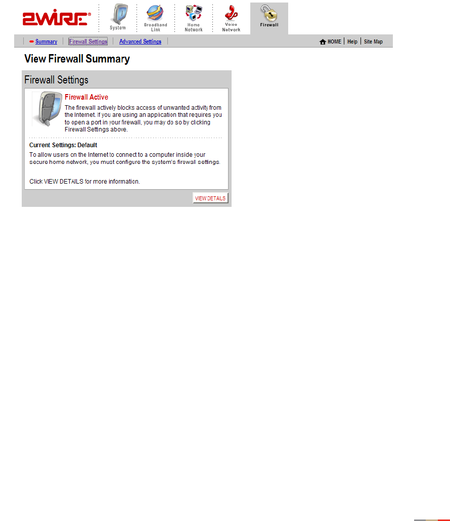
Firewall Tab
40
Viewing Your Firewall Summary
The Firewall Summary page provides summary information and links to the most commonly used security-
related features of your system.
To access the Firewall Summary page:
• Open a Web browser and access the gateway user interface by entering
http://gateway.2wire.net.
• Click the Firewall tab to open the View Firewall Summary page.
Figure 15. View Firewall Summary Page
The Firewall Settings panel displays the Current Settings for your firewall.
•Default. Unsolicited inbound traffic is not allowed to pass through the firewall.
•Custom. Applications are associated with computers on your network.
An access list shows the computers (Devices) on your network and the names of the Allowed Applications
for each computer. When you allow application traffic, external users on the Internet can have limited
access to your home network. This access might be required to allow some programs (such as game
servers or instant messaging software) to operate properly.
For example, a remote game player on the Internet might need to contact the game server program that you
have installed on your home network in order to play against you. Normally, the firewall blocks this
communication. By changing the firewall settings, this communication is permitted to pass through a
“pinhole” in the firewall. This function may be referred to as “port-mapping” or “port-forwarding” in your
software program documentation.

Firewall Tab
41
Click VIEW DETAILS to access the Firewall Details page, which shows a list of all the devices that have
applications configured in the firewall and the details of these configurations.
Figure 16. View Firewall Details Page
If you have the Firewall Monitor enhanced service, the Firewall Monitor panel shows a brief summary of the
number of attacks that were blocked for the current day and week. Click VIEW DETAILS to access the Monitor
the Firewall page.
Hosting an Application
When you host an application on your network for Internet users to access, you must configure the 2Wire
gateway firewall to pass through specific application data to a selected computer.
To host an application:
• Open a Web browser and access the gateway user interface by entering
http://gateway.2wire.net.
• Click the Firewall tab.
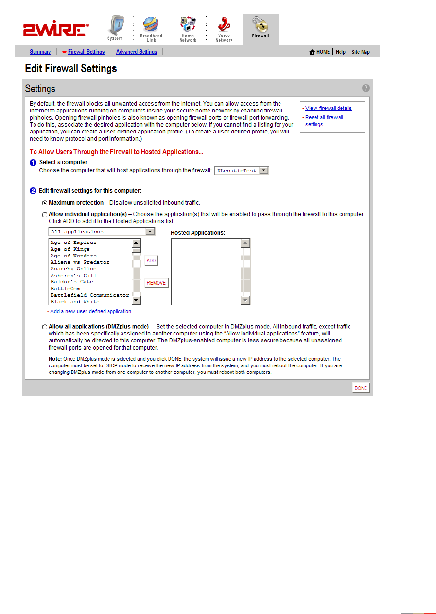
Firewall Tab
42
• Click the Firewall Settings link under the tab to open the Edit Firewall Settings page.
Figure 17. Edit Firewall Settings Page
1. From the Select a computer pull-down menu, select the computer that you wish to host the application.
2. Click the Allow individual application(s) radio button.
3. In the Applications panel, select an application.
4. Click the ADD > button. The application you selected now appears in the Hosted Applications pane.
5. Click DONE.

Firewall Tab
43
To stop hosting an application:
1. In the Hosted Applications panel, select the application you wish to stop hosting.
2. Click the < REMOVE button.
3. Click DONE.
Updating the Application Profile List
If the application you want to host does not appear in the Application Profile list, you may need to update
the application list. If an update is available, the UPDATE APPLICATION LIST button appears above the list of
application profiles. If the application that you want to host is not included in the updated application list,
you may need to add your own application profile.
Adding an Application Profile
If you wish to host an application that is not included in the Application Profile list, you can add an
application using the Add Application Profile page.
An application profile configures your system’s firewall to pass through application-specific data. This
feature is typically used if the application for which you would like to pass through data to a given computer
is new or has been recently updated to a new version.
To create a new application profile:
• Open a Web browser and access the gateway user interface by entering
http://gateway.2wire.net.
• Click the Firewall tab.
• Click the Firewall Settings link under the tab to open the Edit Firewall Settings page.
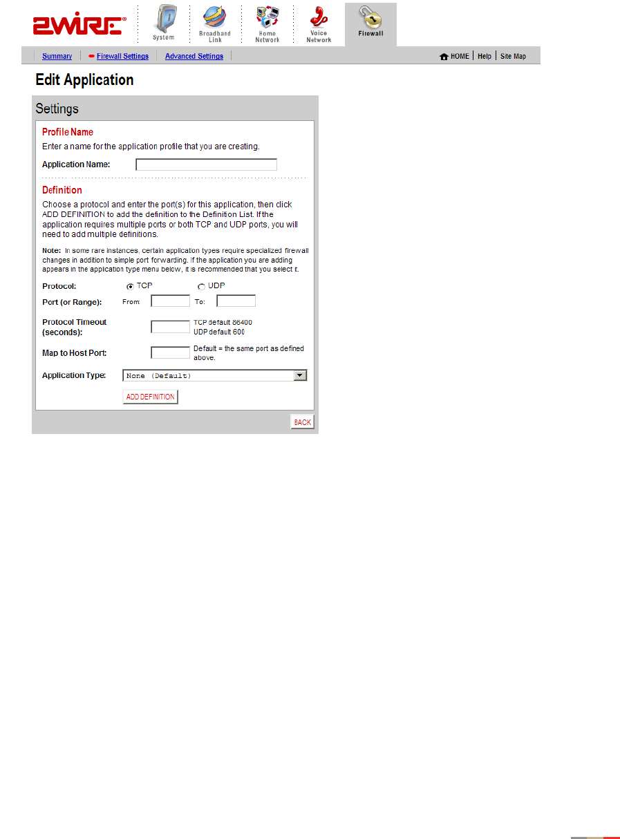
Firewall Tab
44
• In the Applications panel, click the Add a new user-defined application link to open the Edit Application
page.
Figure 18. Edit Application Page

Firewall Tab
45
1. In the Application Name field, enter a name for the application profile. You can enter any name you like,
although it’s recommended that you use the name of the application (for example, Redwing Game
Server).
2. In the Definition panel, create a definition for your application.
A definition consists of a series of protocol-specific ports that are to be allowed through the firewall.
This information should be contained in the documentation provided by the company that produces the
application.
a. In the Protocol field, select the TCP or UDP radio button. If the application you are adding requires
both, you must create a separate definition for each.
b. In the Port (or Range) field, enter the port or port range the application uses.
For example, some applications may require only one port to be opened (such as TCP port 500);
others may require that all TCP ports from 600 to 1000 be opened.
c. In the Protocol Timeout (seconds) field, you may optionally enter a value for the amount of time that
can pass before the application “times out.” You can also leave the field blank, in which case the
system uses the default values (86,400 seconds for the TCP protocol; 600 seconds for the UDP
protocol).
d. In the Map to Host Port field, enter a value that will map the port range you established in step b to
the local computer. For example, if you set the value to 4000 and the range being opened is 100 to
108, the forwarded data to the first value in the range will be sent to 4000. Subsequent ports will
be mapped accordingly; 101 will be sent to 4001, 102 will be sent to 4002, etc.
e. From the Application Type drop-down menu, select the application type. If you do not know the
application type, select None (Default).
3. Click ADD DEFINTION to add the values to the profile definition list.
4. Click DONE.
Repeat these steps for each port or range of ports required for the application profile.
To edit or delete an application profile:
• Open a Web browser and access the 2Wire gateway user interface by entering
http://gateway.2wire.net.
• Click the Firewall tab.
• Click the Firewall Settings link under the tab to open the Edit Firewall Settings page.
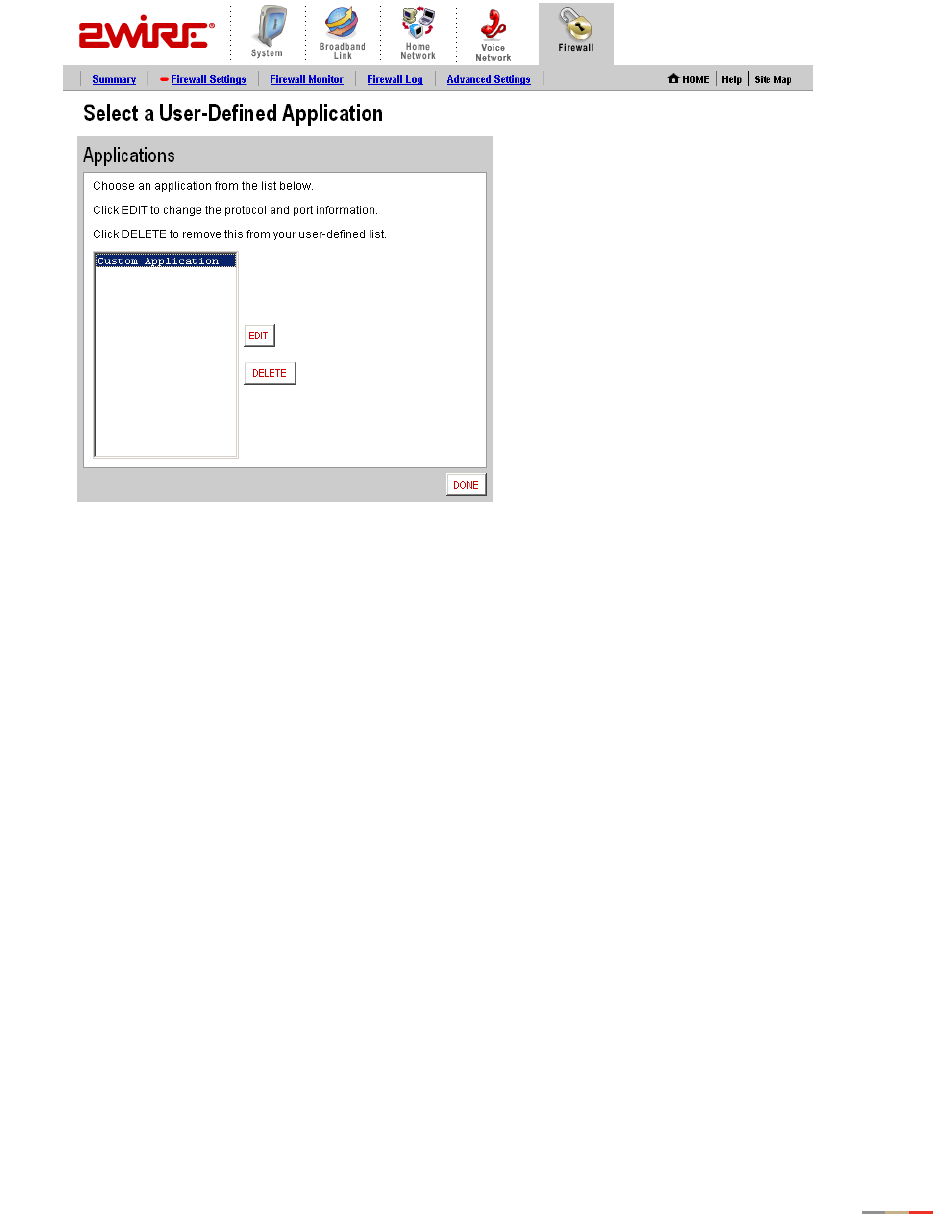
Firewall Tab
46
• In the Applications panel, click the Edit or delete user-defined application link. The Select a Hosted
Application page opens.
Figure 19. Select a Hosted Application Page
1. In the User-Defined Application Profiles panel, highlight the application you wish to edit or delete.
f. To edit the application profile, click EDIT. The Edit Application screen appears. Make the necessary
changes to the application profile and click DONE.
g. To delete the application profile, click DELETE.
Allowing all Applications (DMZplus)
DMZplus is a special firewall mode that is used for hosting applications if you cannot get an application to
work properly using the “Allow individual application(s)” option. When in DMZplus mode, the designated
computer:
• Shares your gateway’s IP address (Router Address).
• Appears as if it is directly connected to the Internet.
• Has all of the unassigned TCP and UDP ports opened and pointed to it.
• Can receive unsolicited network traffic from the Internet.
Although the computer in DMZplus mode appears to Internet users as though it is directly connected to the
Internet, it is still protected by your system firewall. All traffic is inspected by the firewall’s Stateful Packet
Inspection engine and all known hacker attacks continue to be blocked.
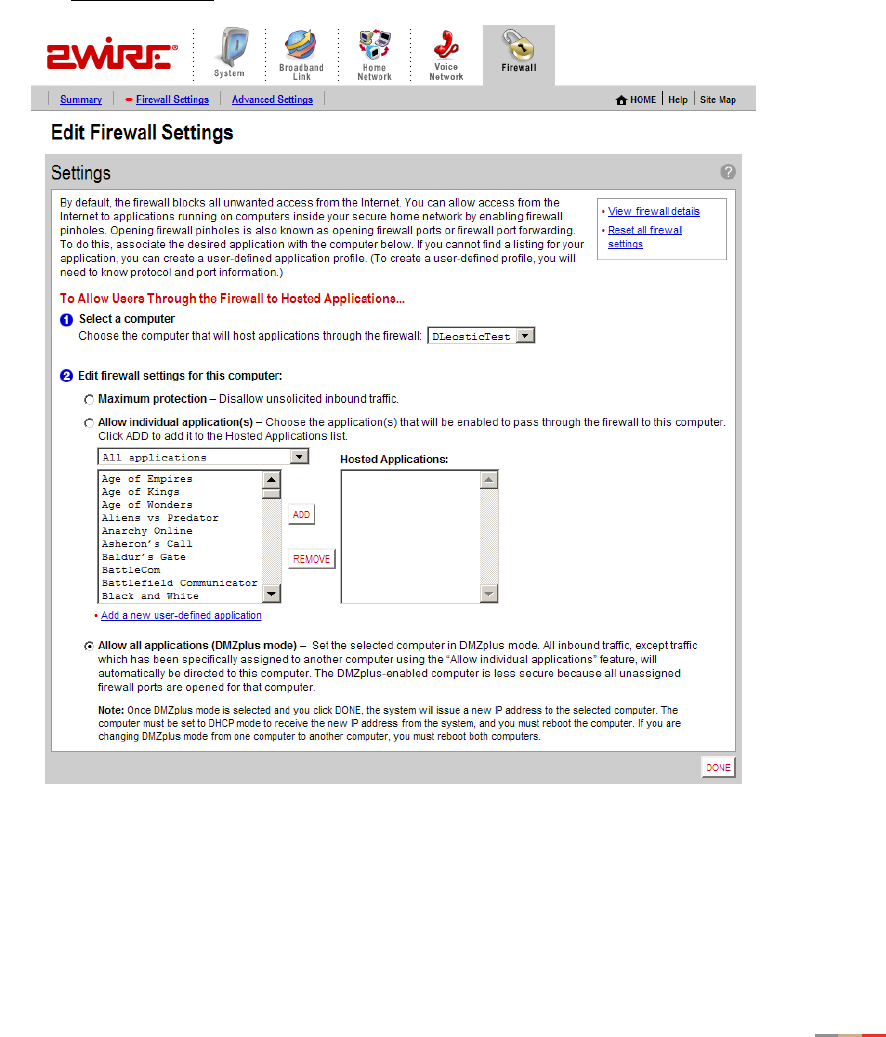
Firewall Tab
47
Because all filtered traffic is forwarded to the designated computer, you should use DMZplus mode with
caution. A computer in DMZplus mode is less secure because all available ports are open and all incoming
Internet traffic is directed to this computer.
To configure DMZplus:
• Open a Web browser and access the 2Wire gateway user interface by entering
http://gateway.2wire.net.
• Click the Firewall tab.
• Click the Firewall Settings link under the tab to open the Edit Firewall Settings page.
Figure 20. Edit Firewall Settings Page
1. From the Select a computer pull-down menu, select the computer to which you would like to have all data
sent.
2. Click Allow all applications (DMZplus mode).

Firewall Tab
48
3. Click DONE.
4. Access the computer that you selected in step 1.
5. Confirm that the computer is configured for DHCP. If it is not, configure it for DHCP.
6. Restart the computer. When the computer restarts, it receives a special IP address from the system
and all unassigned TCP and UDP ports are forwarded to it.
To stop DMZplus:
1. From the Select a computer pull-down menu, select the computer for which you would like to disable
DMZplus.
2. In the Edit firewall settings for this computer pane, click Maximum protection.
3. Click DONE.
4. Access the computer that you selected in step 1. If the computer will continue to automatically obtain
an IP address, proceed to step 5. If the computer will have a static IP address, configure it with a valid
static IP address.
5. Restart the computer.
Viewing the Firewall Log
The 2Wire gateway keeps a log of all firewall-related events that occur. Each log entry contains the date and
time the event occurred, the severity level of the event, and details about the event.
To view the log:
• Open a Web browser and access the 2Wire gateway user interface by entering
http://gateway.2wire.net.
• Click the Firewall tab.

Firewall Tab
49
• Click the Firewall Log link under the tab to open the View Firewall Log page.
Figure 21. View Firewall Log Page
The following table provides additional information about the log entries.
Click CLEAR LOG to clear the log.
Severity • Info. Informational only—the event does not imply a
threat to network security.
• Low. Occurs when the firewall detects a low-level threat
to the network, such as an invalid IP header or invalid
packet length.
• Medium. Occurs when a medium-level threat is detected,
such as an invalid IP fragment offset.
• High. Occurs when an attack is launched against the
network (for example, a SYN Flood).
Details Includes the following information:
• The IP address from which the packet originated.
• The destination IP address of the packet.
• The action that was taken.
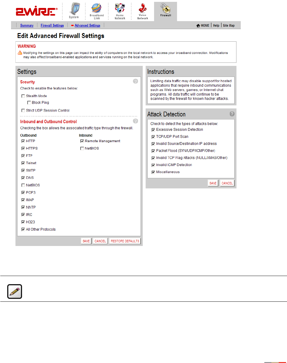
Firewall Tab
50
Configuring the Firewall (Advanced)
The Edit Advanced Firewall Settings page allows you to configure advanced features on your firewall.
Figure 22. Edit Advanced Firewall Settings Page
Note: These features should be used only if you are thoroughly familiar with firewalls and
networking.

Firewall Tab
51
Enabling Advanced Security
Your 2Wire gateway firewall already provides a high level of security. You can configure the firewall to provide
advanced security features, including stealth mode, strict UDP, or block pings.
Stealth Mode
In normal firewall operation, when an unknown remote device makes a request to connect to a user’s
network the firewall does not allow the connection to be made and responds with a “connection not
available” message. This may not discourage a determined hacker, because the message confirms that
there is an active network sending the response. The hacker may then use more sophisticated tools in an
attempt to access your network.
When in stealth mode, the 2Wire gateway firewall does not return any information in response to network
queries; that is, it will appear to the hacker who is trying to access your network that your network does not
exist. This discourages hackers from further attempts at accessing your network, because to them it will
appear as though there is no active network to access.
To enable Stealth Mode:
• Open a Web browser and access the 2Wire gateway user interface by entering
http://gateway.2wire.net.
• Click the Firewall tab.
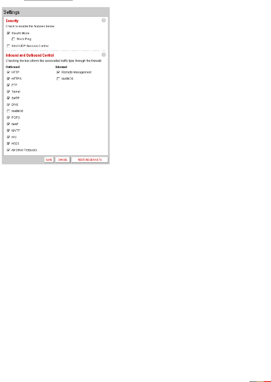
Firewall Tab
52
• Click the Advanced Settings link under the tab to open the Edit Advanced Firewall Settings page.
1. In the Security pane, click the Stealth Mode checkbox.
2. Click SAVE.
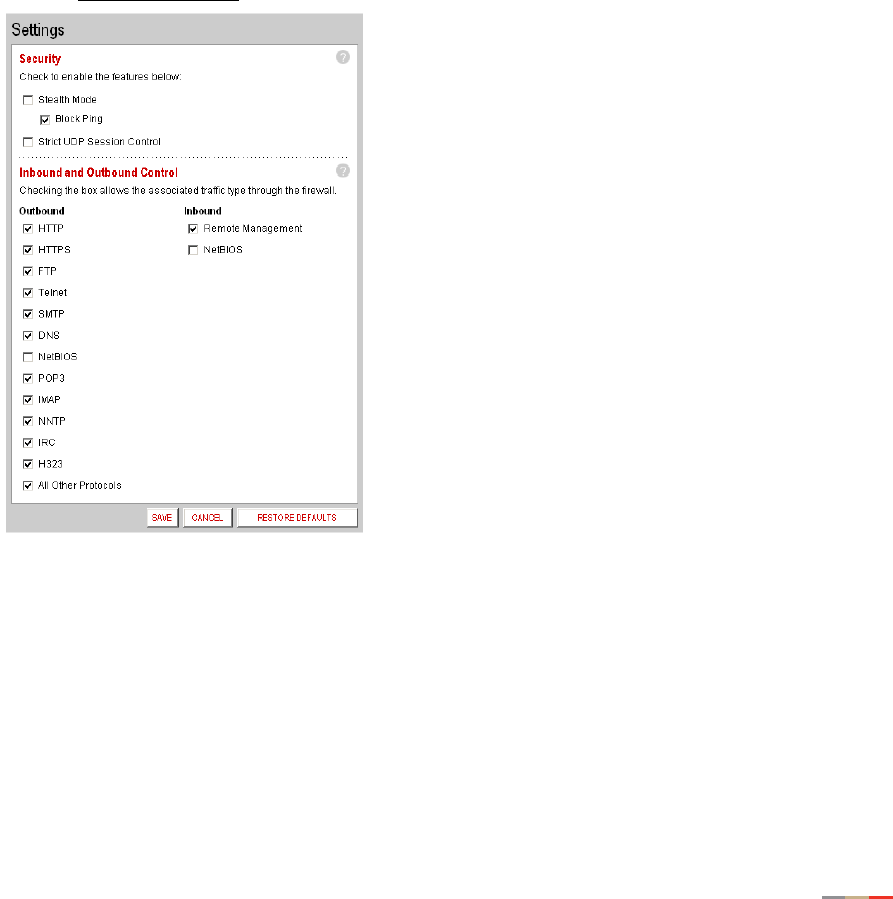
Firewall Tab
53
Block Ping
Ping is a basic Internet program that, when used without malicious intent, allows a user to verify that a
particular IP address exists and can accept requests. Ping is used diagnostically to ensure that a host
computer you are trying to reach is operating. It can also be used to see how long it takes to get a response
back from a specific host computer.
Hackers can use ping to launch an attack against your network, because ping can determine the number
form of the network’s IP address (for example, 105.246.172.72) from the domain name (for example,
www.mynetwork.com). If you enable Block Ping, your network will block all ping requests.
To block ping:
• Open a Web browser and access the 2Wire gateway user interface by entering
http://gateway.2wire.net.
• Click the Firewall tab.
• Click the Advanced Settings link under the tab to open the Edit Advanced Firewall Settings page.
1. In the Security pane, click the Block Pings checkbox.
2. Click SAVE.
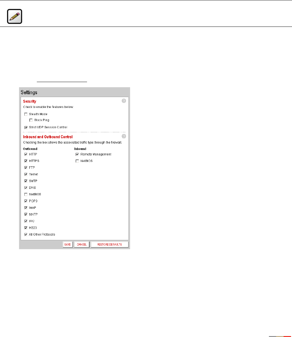
Firewall Tab
54
Strict UDP Session Control
Enabling this feature provides increased security by preventing the 2Wire gateway from accepting packets
sent from an unknown source over an existing connection.
Strict UDP instructs the 2Wire gateway to be more restrictive about what packets are allowed to transmit
over an established connection from a local network computer to the Internet. In addition to relying on
information about the destination (3-tuple), the 2Wire gateway will also use information about the source of
the connection (5-tuple).
To enable strict UDP session control:
• Open a Web browser and access the 2Wire gateway user interface by entering
http://gateway.2wire.net.
• Click the Firewall tab.
• Click the Advanced Settings link under the tab to open the Edit Advanced Firewall Settings page.
1. In the Security pane, click the Strict UDP Session Control checkbox.
2. Click SAVE.
Note: The ability to send traffic based on destination only is required by some applications.
Enabling this feature may not allow some on-line applications to work properly.
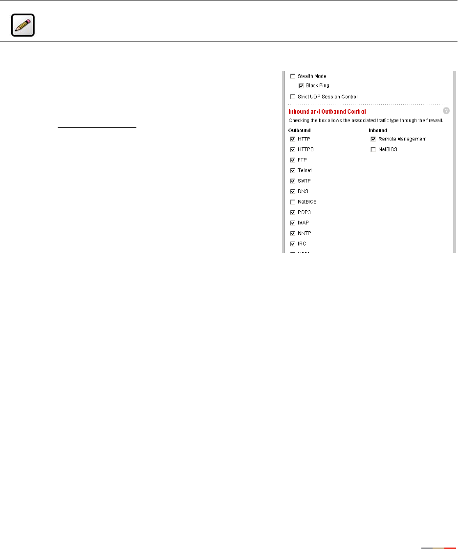
Firewall Tab
55
Allowing Inbound and Outbound Traffic
The Inbound and Outbound Control pane displays some common protocol types. When one of the Inbound
protocol boxes is checked, the firewall allows the corresponding protocol to pass through from the Internet
to the network. If one of the Outbound protocol boxes is checked, the firewall allows the traffic from the
network to pass through the firewall to the Internet.
To block an Inbound or Outbound protocol:
• Open a Web browser and access the 2Wire gateway user
interface by entering http://gateway.2wire.net.
• Click the Firewall tab.
• Click the Advanced Settings link under the tab to open the
Edit Advanced Firewall Settings page.
1. In the Inbound and Outbound Control pane, deselect the
checkbox of the protocol you wish to block.
2. Click SAVE.
Disabling Attack Detection
By default, the 2Wire gateway firewall rules block the attack
types listed in the Attack Detection pane. There are some
applications and devices that require the use of specific data
ports through the firewall. The gateway allows users to open the necessary ports through the firewall using
the Firewall Settings page. If the user requires that a computer have all incoming traffic available to it, this
computer can be set to the DMZplus mode. While in DMZplus mode, the computer is still protected against
numerous broadband attacks (for example, SYN Flood or Invalid TCP flag attacks).
In rare cases, the incoming traffic may be inadvertently blocked by the firewall (for example, when
integrating with external third-party firewalls or VPN servers). You may need to disable one or more of the
attack detection capabilities for any device placed in the DMZplus. In this case, the third-party server
provides the attack protection normally provided by the gateway.
Note: If you configure the firewall to block an Inbound protocol, you may disable support for
hosted applications that require that type of protocol.

Firewall Tab
56
The following table lists the attacks for which the gateway firewall filters continuously check.
To disable attack detection for a specific port:
• Open a Web browser and access the 2Wire gateway user interface by entering
http://gateway.2wire.net.
• Click the Firewall tab.
Attack Description and Action Taken
Excessive Session Detection When enabled, the firewall will detect applications on the
local network that are creating excessive sessions out to
the Internet. This activity is likely due to a virus or “worm”
infected computer (for example, Blaster Worm). When the
event is detected, the gateway displays a HURL warning
page.
TCP/UDP Port Scan A port scan is a series of messages sent by someone
attempting to break into a computer to learn which
computer network services, each associated with a well-
known port number (such as UDP and TCP), the computer
provides. When enabled, the firewall detects UDP and TCP
port scans, and drops the packet.
Invalid Source/Destination IP
address
When enabled, the firewall will verify IP addresses by
checking for the following:
IP source address is broadcast or multicast — drop
packet.
TCP destination IP address is not unicast — drop packet.
IP source and destination address are the same — drop
packet.
Invalid IP source received from private/home network —
drop packet.
Packet Flood (SYN/UDP/ICMP/
Other)
When enabled, the firewall will check for SYN, UDP, ICMP,
and other types of packet floods on the local and Internet
facing interfaces and stop the flood.
Invalid TCP Flag Attacks (NULL/
XMAS/Other)
When enabled, the firewall will scan inbound and
outbound packets for invalid TCP Flag settings, and drop
the packet to prevent SYN/FIN, NULL, and XMAS attacks.
Invalid ICMP Detection The firewall checks for invalid ICMP/code types, and drops
the packet.
Miscellaneous The firewall checks for the following:
Unknown IP protocol — drop packet.
Port 0 attack detected — drop packet.
TCP SYN packet — drop packet.
Not a start session packet — drop packet.
ICMP destination unreachable — terminate session.
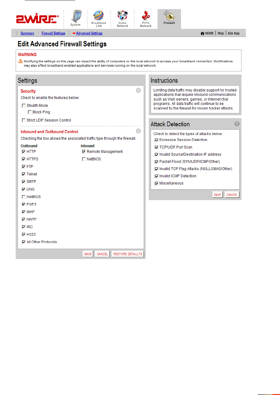
Firewall Tab
57
• Click the Advanced Settings link under the tab to open the Edit Advanced Firewall Settings page.
Figure 23. Edit Advanced Firewall Settings Page
1. In the Attack Detection panel, deselect the appropriate checkbox.
2. Click SAVE.

58
Management and Diagnostic Console
This chapter describes the 2Wire gateway Management and Diagnostic Console (MDC). The Management
and Diagnostic Console provides information about the status of the 2Wire gateway, its broadband network
connections, attached home networking devices, system and security information, and a running log of any
error conditions.
You can use the tools provided to:
• View configuration and service provisioning information.
• View operation logs.
• Perform diagnostic tests.
• Configure the gateway.
The following sections describe how to access the Management and Diagnostic Console, use the
diagnostic and configuration tools, and modify settings.
Accessing the MDC
To access the MDC from your in-home or office network, enter the following URL:
http://gateway.2wire.net/management
Using the MDC
After you access the Management and Diagnostic Console, a navigation bar allows you to quickly select
pages on the site. The navigation bar consists of the following links:
Note: The MDC pages available are dependent on the 2Wire gateway software release. The
MDC pages shown in this chapter are for 2Wire gateways running software release 4.21.x If
your gateway is running a software release earlier than 4.21.x, some of these pages may not
be available.
Group Link
Summary System Summary
Broadband Link Summary
Statistics
Detailed Statistics
Configure
Local Network Status
Statistics

Management and Diagnostic Console
59
Local Network
Device List
Wireless
Configure
Firewall Settings
Detailed Information
Advanced Settings
Voice Summar y
Configure Server
Configure Line Association
Troubleshooting DSL Diagnostics
Event Log
Network Tests
Upgrade History
Resets
Advanced Syslog Settings
Provisioning Info
Configure Time Services
Configure Services
Static Routes
DNS Resolve
Traffic Shaping
Link Manager
Detailed Log
Note: The link groups that display are dependent on the 2Wire gateway model. For example,
DSL Diagnostics will display only if a user has a gateway that connects to the Internet via DSL.
Group Link

Management and Diagnostic Console
60
System Summary Page
The System Summary page shows general information about the 2Wire gateway, its configuration, and
components. For example, it shows the hardware and software version being used by the 2Wire gateway.
Broadband Link Pages
The Broadband Link pages show summary, detailed status, and statistical information about the 2Wire
gateway broadband link; and lets you change configuration settings. For example, the Statistics page shows
current upstream and downstream DSL data rates.
Local Network Pages
Local Network pages show the general operating status of the home network, and statistics associated
with network interfaces. For example, the Statistics page shows the transmit and receive packet count for
Ethernet, Wireless, HomePNA, and USB interfaces.
Firewall Pages
Firewall pages allow you to access settings and detailed information for the gateway’s firewall, and to
configure the firewall if necessary. For example, you can use the Firewall Settings page to access
applications that are usually blocked by the firewall.
Voice Pages
Voice pages show summary information about the VoIP network, and allow you to configure the servers and
voice lines. For example, the Voice - Configure Server page allows you to set up your VoIP server.
Troubleshooting Pages
Troubleshooting pages allow you to view detailed logs that maintain a record of all significant 2Wire gateway
events, and to perform diagnostic tests. For example, if you are experiencing connection problems you can
use the Ping tool on the WAN Tests page to ensure that the 2Wire gateway can “ping” a designated IP
address.
Advanced Pages
Advanced pages provide detailed information and sophisticated diagnostics that, in general, should only be
accessed by technically advanced users.

Management and Diagnostic Console
61
Remote Management Feature
Management and Diagnostic Console pages that affect gateway configuration can be accessed remotely
only if your organization has enabled the Remote Management feature. If the feature is not enabled, an
error message will display when you click the link to access the following pages.
• Broadband Link - Configuration
• Local Network - Configuration
• Firewall - Settings
• Firewall - Detailed Information
• Firewall - Advanced Settings
• Troubleshooting - Configure Logs
• Troubleshooting - Resets
• Advanced - Syslog Settings
• Advanced - Configure Time Services
• Advanced - Configure Services
• Advanced - Static Routes
• Advanced - DNS Resolve
• Advanced - Traffic Shaping
The following section shows Management and Diagnostic Console pages and describes how to use the
information provided to troubleshoot the 2Wire gateway.
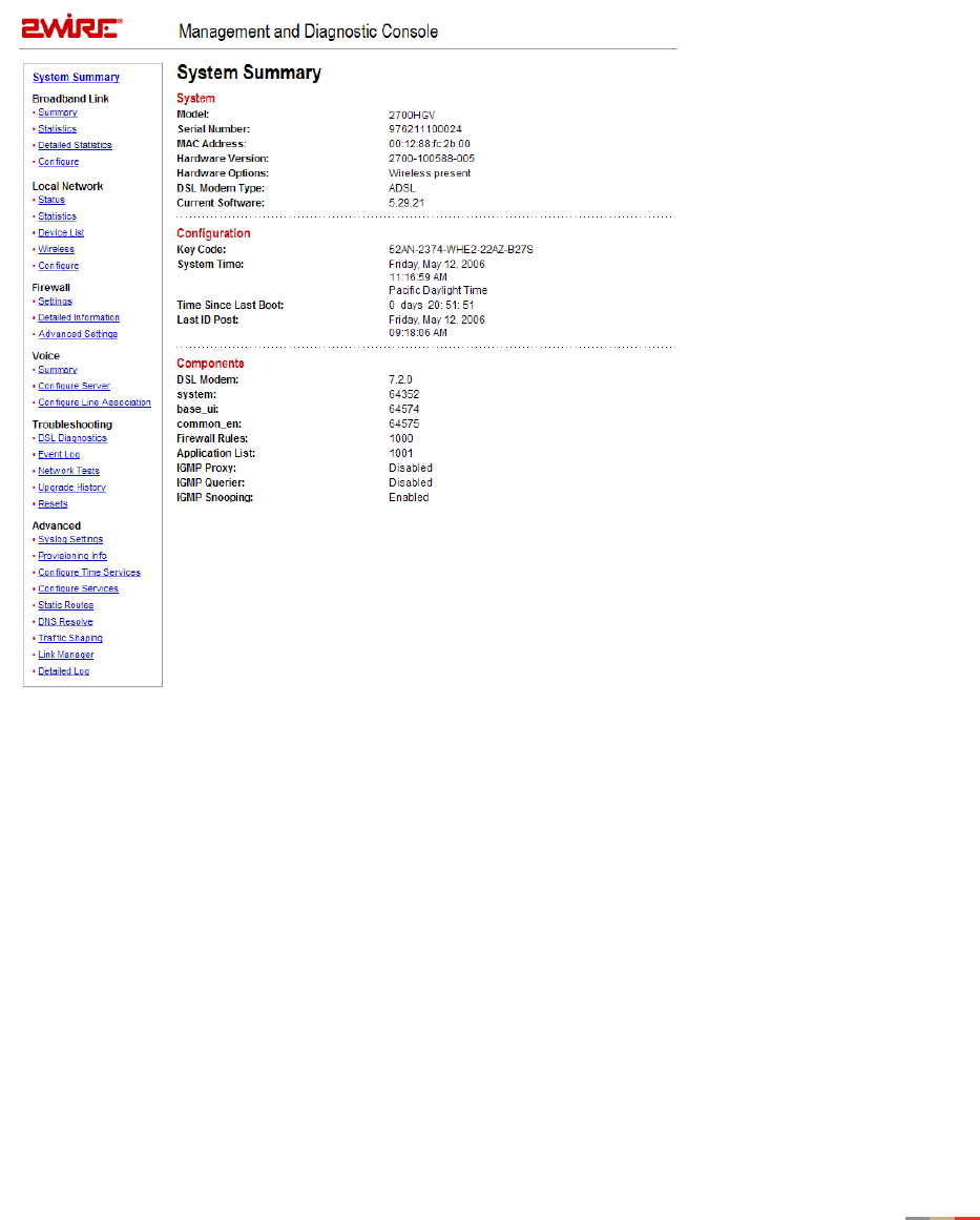
Management and Diagnostic Console
62
System Summary Page
The System Summary page shows general information about the 2Wire gateway, its configuration, and
components.
Figure 24. MDC System Summary Page
Depending on the service provider and the components installed, the System Summary page includes the
following information:
Item Description
System
Model 2Wire gateway model number (for example,
“2700HGV Gateway”).
Serial Number 2Wire gateway serial number.
MAC Address 2Wire gateway MAC address.

Management and Diagnostic Console
63
Hardware Version 2Wire gateway hardware version.
Hardware Options The type of peripheral device installed.
DSL Modem Type ADSL or ISDN.
Current Software 2Wire gateway software version.
Configuration
Key Code The key code associated with the current
provisioning settings. The value is
Unprovisioned if the 2Wire gateway has not yet
been provisioned.
System Time The day, month, year, and time; or “Retrieving
date and time settings from Internet” if not set.
Time Since Last Boot The time elapsed since the 2Wire gateway was
last restarted.
Last ID Post The time elapsed since the 2Wire gateway
communicated with the configuration server.
Components
DSL Modem DSL modem software version.
Firewall Rules Current version of the installed firewall rules
database.
Application List Current version of the application list.
Note: The contents of the Components list varies according to service provider-specific
information. For example, the Components list may contain language files (such as
common_en, common_es, or common_fr); user interface files (such as base_ui); or VoIP files
(such as base_voice).
Item Description
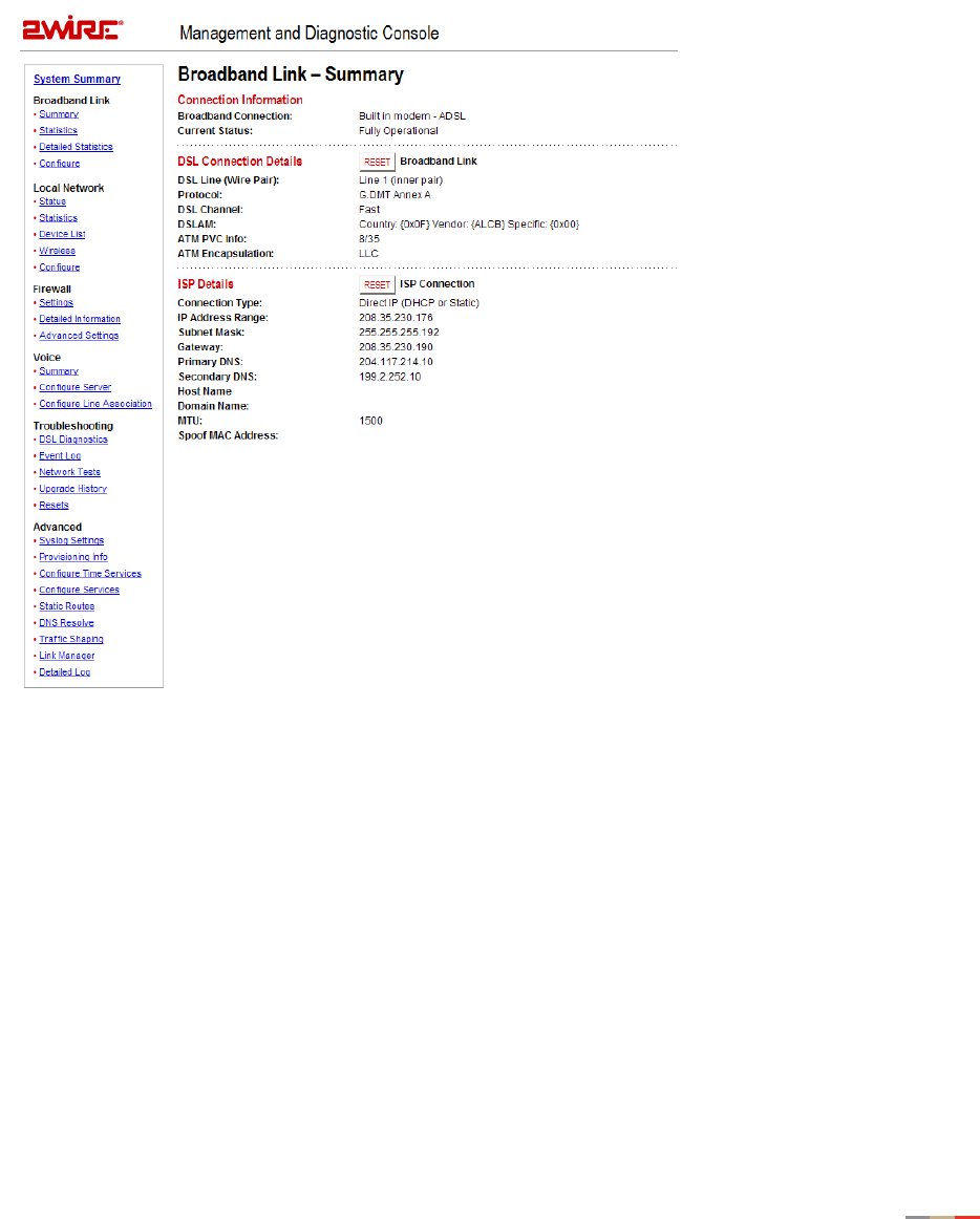
Management and Diagnostic Console
64
Broadband Link - Summary Page
The Broadband Link - Summary page allows you to view 2Wire gateway broadband connectivity-related
settings, and reset the Broadband Link and ISP Connection.
Figure 25. MDC Broadband Link Summary Page
The Broadband Link – Summary page includes the following information:
Item Description
Connection Information
Broadband Connection Built-in ADSL Modem or External Broadband Modem via
Ethernet.

Management and Diagnostic Console
65
Current Status The current operating condition of the broadband link.
Fully operational. The broadband link is operational
(including connection to ISP and other services).
Initializing. The broadband link is preparing to connect.
Establishing link. The broadband link is connecting.
No physical link signal. No physical signal detected on the
broadband link.
Physical connection. The broadband link is connected.
Error. There is a broadband link error.
DSL Connection Details (for DSL models only)
DSL Line (Wire Pair) Line 1 (inner pair), Line 2 (outer pair), or Searching for DSL
signal. During installation, the 2Wire gateway auto detects
whether the DSL signal is on line 1 or line 2.
Protocol G.dmt, G.lite, or ANSI (T1.413).
DSL Channel Fast or Interleaved.
DSLAM DSLAM vendor identification. For G.dmt or G.lite protocol,
values are Country, Vendor, and Specific. For ANSI (T1.413)
protocol, values are ID, Rev (Revision), and Std (Standard).
ATM PVC Info The ATM VPI/VCI.
ATM Encapsulation LLC or VCMux.
ISP Details
Connection Type The method by which the 2Wire gateway connects to the ISP:
Direct_IP, PPPoA, or PPPoE. For the HomePortal 1000, direct
uses an RFC2684 (formerly RFC 1483) bridged Ethernet
connection without FCS (PID=0x00-07) format.
User Name The 2Wire gateway user name.
PPPoE Access Concentrator This field is present only when the connection type is PPPoE.
PPPoE Service The type of PPPoE services being used. This field is present
only when the connection type is PPPoE.
IP Address Range The broadband address of the 2Wire gateway.
Subnet Mask The subnet mask to be used by the 2Wire gateway on the
broadband link.
Gateway The IP address of the default gateway (default router) that
the 2Wire gateway connects to on the broadband link.
Item Description

Management and Diagnostic Console
66
If there is an error on the broadband link or with the ISP connection, click the Reset Broadband Link or Reset
ISP Connection button to reset the connections.
Primary DNS The IP address of the primary DNS server that the 2Wire
gateway is to use for DNS name resolution on the broadband
link.
Secondary DNS The IP address of the secondary DNS server that the 2Wire
gateway is to use for DNS name resolution on the broadband
link.
Host Name The 2Wire gateway host name. This field is only present if
the user configures the 2Wire gateway with a host name.
Domain Name The domain name associated with the 2Wire gateway on the
broadband link.
MTU Maximum size of the packets sent from a computer to the
network.
Spoof MAC Address Either Disabled (if the default factory-set MAC address is
used) or Enabled (if the computer’s MAC address is used).
Item Description
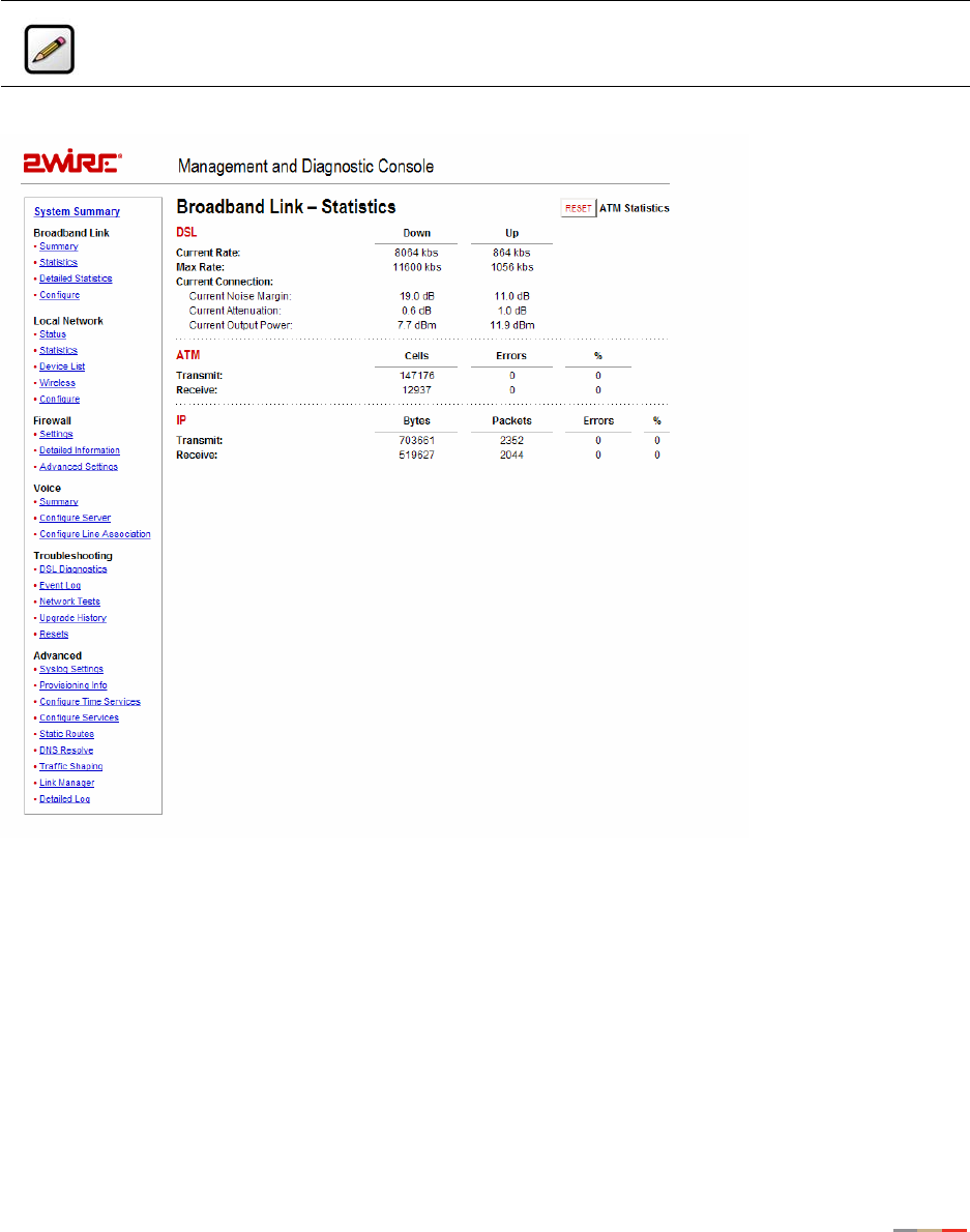
Management and Diagnostic Console
67
Broadband Link - Statistics Page
The Broadband Link - Statistics page shows statistics associated with the 2Wire gateway broadband link.
Figure 26. MDC Broadband Link Statistics Page
The Broadband Link – Statistics page includes the following information:
Note: To update the information displayed on this page, click the browser’s Refresh button.
Item Description
DSL (for DSL models only)
Current Rate The DSL downstream and upstream rate, in kilobits.
Max Rate The maximum DSL downstream and upstream rate, in
kilobits.

Management and Diagnostic Console
68
To reset the broadband link statistics, click the Reset button.
Current Connection Current Noise Margin. The current downstream and
upstream noise margin in dB.
Current Attenuation. The current downstream and
upstream DSL attenuation in dB.
Current Output Power. The current downstream and
upstream DSL transmit and receive power in dB.
ATM
Transmit The cumulative number of cells transmitted, and the
number and percentage transmitted in error.
Receive The cumulative number of cells received, and the number
and percentage received in error.
IP
Transmit The cumulative number of IP packets transmitted, the
cumulative number of IP payload bytes transmitted, and
the number and percentage transmitted in error.
Receive The number of bytes and packets received, and the
number and percentage received in error.
Item Description
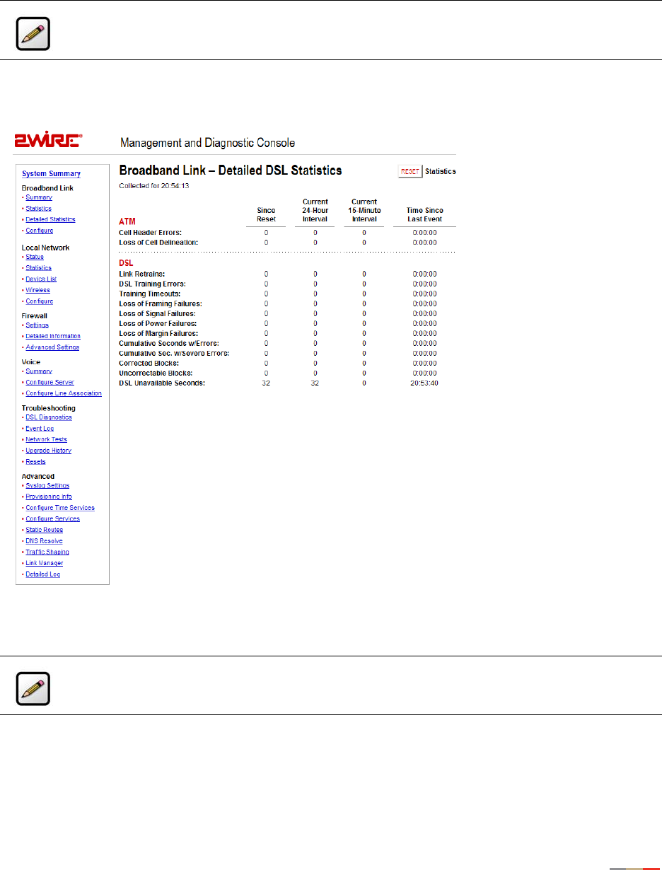
Management and Diagnostic Console
69
Broadband Link - Detailed DSL Statistics Page
The Broadband Link – Detailed DSL Statistics page shows a set of cumulative DSL statistics associated
with the 2Wire gateway.
Figure 27. MDC Broadband Link Detailed DSL Statistics Page
Note: This link is present only if the 2Wire gateway connects to the Internet via ADSL.
Note: To update the information displayed on this page, click the browser’s Refresh button.

Management and Diagnostic Console
70
The Broadband Link – Detailed DSL Statistics page includes the following information:
Item Description
ATM
Cell Header Errors The number of ATM cell header CRC errors since the
2Wire gateway was last restarted, and the elapsed time
since the last cell header error.
Loss of Cell Delineation The number of ATM loss of cell delineation errors since
the 2Wire gateway was last restarted, and the elapsed
time since the last loss of cell delineation error.
DSL
Link Retrains The number of DSL retrains since the 2Wire gateway was
last restarted, and the time elapsed since the last
retrain.
DSL Training Errors The number of failed DSL retrains since the 2Wire
gateway was last restarted, and the elapsed time since
the last failed retrain.
Training Timeouts The number of timeouts waiting for response from ATU-C
since the 2Wire gateway was last restarted, and the
elapsed time since the last initialization timeout.
Loss of Framing Failures The number of DSL loss of framing failures since the
2Wire gateway was last restarted, and the elapsed time
since the last line search initialization.
Loss of Signal Failures The number of DSL loss of signal failures since the 2Wire
gateway was last restarted, and the elapsed time since
the last loss of signal failure.
Loss of Power Failures The number of DSL loss of power indications from the
ATU-C since the 2Wire gateway was last restarted, and
the elapsed time since the last loss of power indication.
Loss of Margin Failures The number of DSL loss-of-margin failures at current data
rate since the 2Wire gateway was last restarted, and the
elapsed time since the last loss of margin failure.
Cumulative Seconds w/Errors The number of cumulative errored seconds since the
2Wire gateway was last restarted, and the elapsed time
since the last error.

Management and Diagnostic Console
71
To reset the DSL statistics, click the Reset button.
Cumulative Sec.w/Severe
Errors
The number of severely errored seconds since the 2Wire
gateway was last restarted, and the elapsed time since
the last severely errored second.
Corrected Blocks The number of corrected DSL superframes that had data
errors detected during reception.
Uncorrectable Blocks The number of uncorrected DSL superframes that had
data errors detected.
DSL Unavailable Seconds The number of unavailable seconds (modem downtime)
since the 2Wire gateway was last restarted, and the
elapsed time since the last unavailable second.
ISP Connection Establishment The number of times the ISP connection was established
since the statistics were last reset, and the elapsed time
since the last establishment.
Item Description
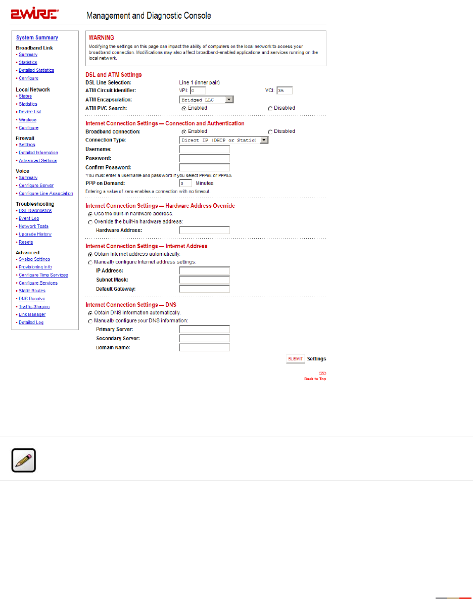
Management and Diagnostic Console
72
Broadband Link - Configuration Page
The Broadband Link – Configuration page allows you to modify specific broadband connection settings.
Figure 28. MDC Broadband Link Configuration Page
Note: Modifying the settings on this page can impact the ability of computers on the local
network to access the broadband connection. You should modify these settings ONLY if you are
thoroughly familiar with networking.

Management and Diagnostic Console
73
Modifying DSL and ATM Settings
By default, the gateway automatically detects which DSL line to use. The DSL and ATM Settings pane allows
you to select a DSL line and manually configure your ATM settings.
To modify DSL or ATM settings:
1. From the DSL Line Selection pull-down, select Automatic, Line 1(inner pair), or Line 2 (outer pair).
2. In the ATM Circuit Identifier VPI and VCI fields, enter the VPI and VCI you want the gateway to use to
connect to the ISP.
3. From the ATM Encapsulation pull-down menu, select VC-Mux or LLC.
4. In the ATM/PVC Search field, click the Enabled or Disabled radio button.
5. Click the Submit button.
Modifying Internet Connection and Authentication Settings
The Internet Connection Settings - Connection and Authentication pane allows you to modify the method by
which you connect to the Internet.
To modify Internet connection and authentication settings:
1. Ensure that the Broadband connection Enabled radio button is selected (default).
2. From the Connection Type pull-down menu, select the connection type (either Direct IP (DHCP or Static),
PPPoE, or PPPoA).
If you connect via PPPoE or PPPoA, proceed to step 2. If you connect via Direct IP, proceed to step 5.
Direct IP connection does not require a user name or password.
3. In the Username field, enter your user name.
4. In the Password field, enter your password.
5. In the Confirm Password field, re-enter your system password.
6. Click the Submit button.
The PPP on Demand field allows you to enable PPP on-demand. If the value is set to 0 minutes, the PPP
session will be persistent (always-on). If the value is between 1 to 10080 minutes, the PPP session will
timeout if the 2Wire gateway does not detect outbound traffic destined for the Internet in the specified time.
When the 2Wire gateway detects outbound traffic, the session is reestablished.
Note: By default, the minimum timeout value is 3 minutes.

Management and Diagnostic Console
74
Modifying Hardware Address
By default, the 2Wire gateway uses its built-in hardware address. The Internet Connection Settings -
Hardware Address Override pane allows you to manually override the MAC address of the broadband
connection, which is sometimes required for cable modems that perform MAC address authentication.
To modify the hardware address:
1. Click the Override the built-in hardware address radio button.
2. In the Hardware Address field, enter the alternative hardware address.
3. Click the Submit button.
Modifying Internet Address Settings
By default, the 2Wire gateway automatically obtains its Internet address. The Internet Connection Settings -
Internet Address pane allows you to manually configure your Internet address settings.
To manually configure your Internet address settings:
1. Click the Manually configure Internet address settings radio button.
2. In the IP Address field, enter the IP address you want the 2Wire gateway to use.
3. In the Subnet Mask field, enter the subnet mask you want the 2Wire gateway to use.
4. In the Default Gateway field, enter the default gateway address you want the 2Wire gateway to use.
5. Click the Submit button.
Modifying DNS Information
By default, the 2Wire gateway automatically obtains DNS server addresses via DHCP. The Internet
Connection Settings - DNS pane allows you to manually configure your DNS information.
To manually configure your DNS information:
1. Click the Manually configure your DNS information radio button.
2. In the Primary Server field, enter the IP address of the primary DNS server that the 2Wire gateway is to
use for DNS name resolution.
3. In the Secondary Server field, enter the IP address of the secondary DNS server that the 2Wire gateway
is to use for DNS name resolution.
4. In the Domain Name field, enter the specific domain name to be used by the 2Wire gateway.
5. Click the Submit button.
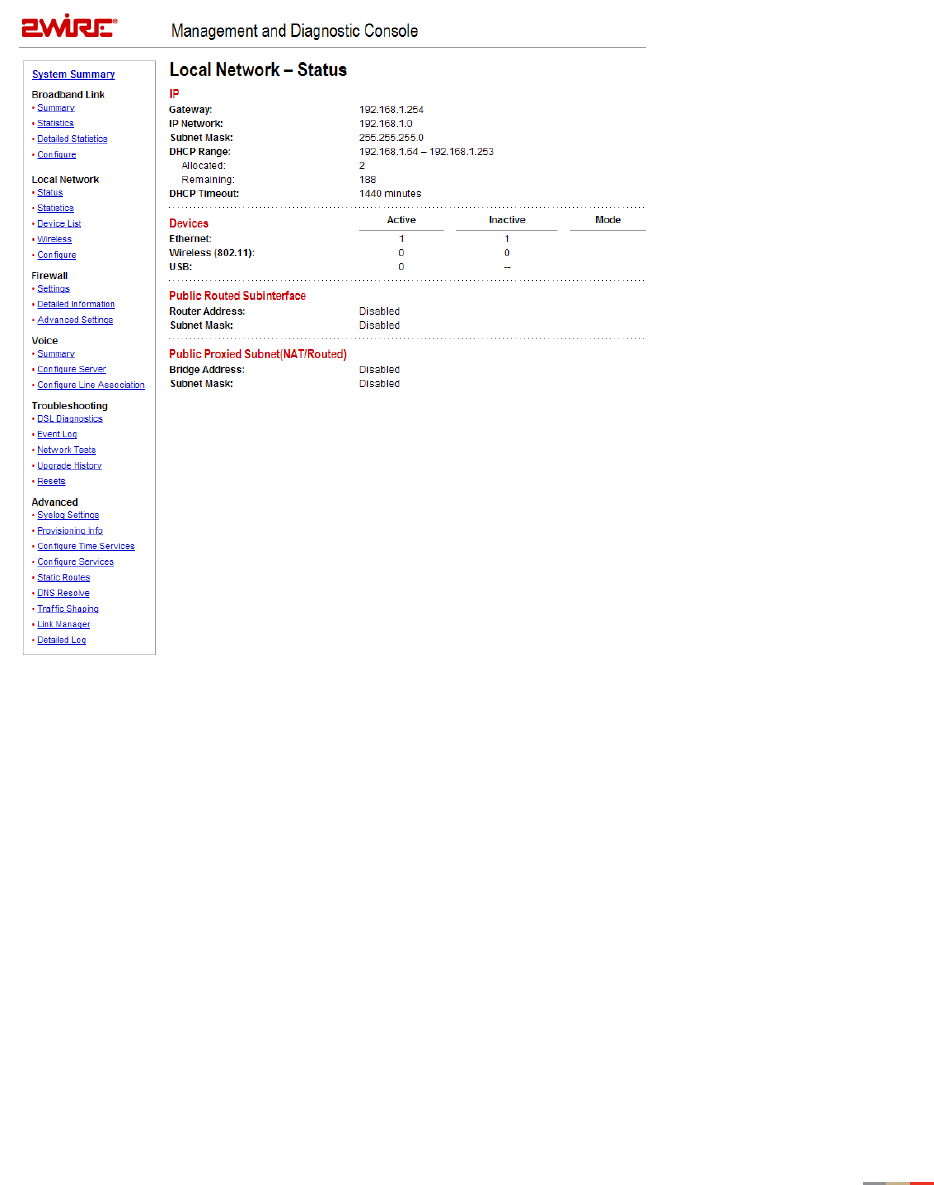
Management and Diagnostic Console
75
Local Network - Status Page
The Local Network – Status page shows the status of the local network.
Figure 29. MDC Local Network Status Page
The Local Network – Status page includes the following information:
Item Description
IP
Gateway The IP address allocated to the 2Wire gateway.
IP Network The IP address used by the network.
Subnet Mask The subnet mask allocated to the 2Wire gateway.
DHCP Range The range of IP addresses available on the network, the
number of addresses Allocated, and the number of
addresses Remaining.

Management and Diagnostic Console
76
DHCP Timeout The time, in minutes, before the DHCP lease must be
renewed.
Devices
Ethernet The number of Active and Inactive Ethernet devices on
the network.
Wireless (802.11) The number of Active and Inactive wireless devices on the
network.
USB Specifies whether a USB device is present (Active) on the
network. If a USB device is not present, the value is
Inactive.
Public Network
Router Address Defines a separate network on the home side.
Subnet Mask The subnet mask allocated for public address.
Bridge Network
Router Address Creates a bridge network with the broadband.
Subnet Mask The subnet mask allocated for public address.
Note: If you have Enhanced Services (such as Internet Access Control) installed, the specific
service and its status display in the Devices panel.
Item Description
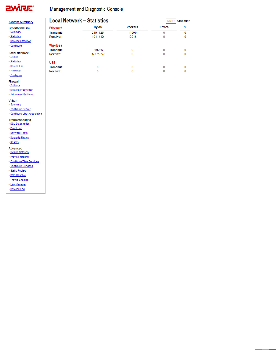
Management and Diagnostic Console
77
Local Network - Statistics Page
The Local Network – Statistics page shows information about the interfaces on the local network.
Figure 30. MDC Local Network Statistics Page
The Local Network – Statistics page includes the following information:
Item Description
Ethernet
Transmit The cumulative number of frames transmitted over the
Ethernet home network interface, the number of payload
bytes transmitted, and the number and percentage of
transmitted packets in error.

Management and Diagnostic Console
78
To reset the local network statistics, click the Reset button.
Receive The cumulative number of frames received over the
Ethernet home network interface, the number of payload
bytes received, and the number and percentage of
received packets in error.
Wireless (this field is present only on wireless 2Wire gateway models)
Transmit The cumulative number of frames transmitted over the
wireless home network interface, the number of payload
bytes transmitted, and the number and percentage of
transmitted packets in error.
Receive The cumulative number of frames received over the
wireless home network interface, the number of payload
bytes received, and the number and percentage of
received packets in error.
USB
Transmit The cumulative number of frames transmitted over the
USB home network interface, the number of payload bytes
transmitted, and the number and percentage of
transmitted packets in error.
Receive The cumulative number of frames received over the USB
home network interface, the number of payload bytes
received, and the number and percentage of received
packets in error.
Item Description
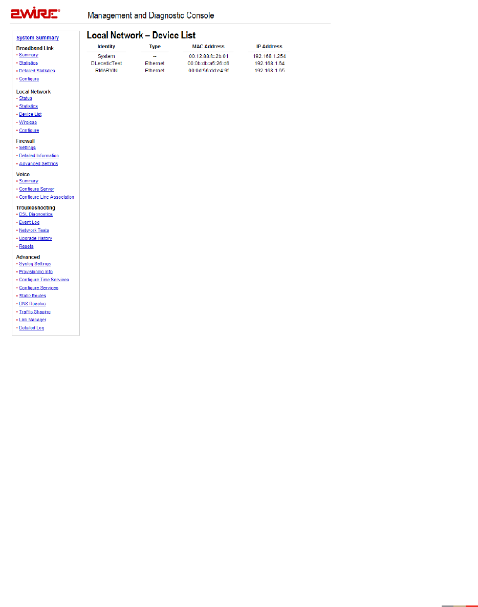
Management and Diagnostic Console
79
Local Network - Device List Page
The Local Network - Device List page displays information about each device in the local network.
Figure 31. MDC Local Network Device List Page
The following information is displayed.
•Identity. The name of the device. If the device does not have a name associated with it, the device IP
address is displayed.
•Type. The type of connection used by the device to connect to the local network: Ethernet, USB, or
Wireless.
•MAC Address. The hardware address used by the device.
•IP Address. The IP address used by the device.
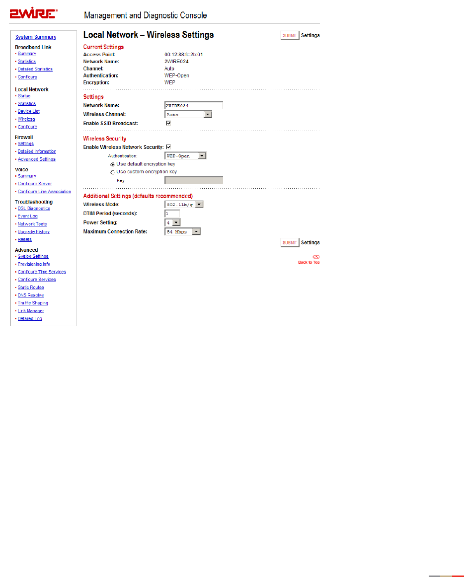
Management and Diagnostic Console
80
Local Network - Wireless Settings Page
The Local Network - Wireless Settings page allows you to view or change the wireless settings with which
your gateway is configured.
Figure 32. MDC Local Network Wireless Settings Page
The Current Settings panel shows the 2Wire gateway’s wireless access point settings.
•Access Point. The designated name of the wireless access point.
•Network Name. The name assigned to your wireless network. The default is 2WIREXXX, where XXX
represents the last three digits of your 2Wire gateway serial number (for example, 2WIRE954).
•Channel. The radio frequency band the access point uses for your wireless network (the default is 6).
Wireless adapter cards auto-detect the channels to use. If you are having problems with your wireless
network, it could be due to radio interference. You can change the wireless channel to see if
interference is reduced on a different channel.
•Authentication. The security method used to ensure that users are authorized to access the wireless
network: WEP-Open, WEP-Shared, or WPA-PSK.
•Encryption. The security setting that makes it difficult for unauthorized users to access your network.
Management and Diagnostic Console
81
The Settings panel allows you to change the Network Name and Wireless Channel, and enable SSID
broadcast.
Customizing Security Settings
You should always enable encryption for wireless communication. When encryption is enabled, you must
define an encryption key for the 2Wire gateway’s wireless access point and configure that same key on each
wireless client that will use your 2Wire gateway wireless network.
You can customize the following wireless settings in the Wireless Security panel.
1. From the Authentication pull-down menu, select an authentication setting: WEP-Open, WEP-Shared, or
WPA-PSK.
Open authentication allows users to configure their wireless adapter as either Open or Shared; in either
case an encryption key is required. Shared authentication allows users to configure their wireless
adapter for Shared authentication, which requires an encryption key. WPA-PSK requires that users
configure their wireless adapter using TKIP.
2. To use the encryption key that came with your gateway, click the Use default encryption key radio button.
To create a custom encryption key, click the Use custom encryption key radio button.
If you select Use custom encryption key, you can define a 64-bit or 128-bit encryption key. For 64-bit
encryption, in the Key field enter a 10-digit hexadecimal number. For 128-bit encryption, enter a 26-digit
hexadecimal number. A hexadecimal number uses the characters 0-9, a-f, or A-F.
3. Click the Submit button.
Additional Settings
The Additional Settings panel allows you to customize wireless settings. In general, it is recommended that
you leave the default settings in place; however, if you are experiencing connection or performance
difficulties, altering these settings may improve performance.
•Wireless Mode. Allows you to force the gateway to use 802.11b/g, 802.11b-only, or 802.11g-only
modes of operation.
•DTIM Period (seconds). Determines at which interval the access point will send its broadcast traffic.
The default value is 1 second.
•Power Setting. Allows you to select the power level for your wireless connection. The default list is 1 to
4; additional options may appear based on the service provider’s configuration.
•Maximum Connection Rate. The maximum rate at which your wireless connection works (1, 2, 5.5, 11,
or 22 Mbps for 802.11b-based models; 1, 2, 5.5, 11, 6, 9, 12, 24, 36, 48, or 54 Mbps for 802.11b/
g-based models).
Note: If encryption is enabled, each wireless client must be configured with the encryption key
defined on the system before it can operate on your wireless network.
Note: Because the fields that display are dependent on the type of wireless adapter you are
using, some of these settings may not display.
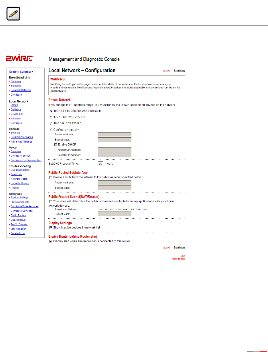
Management and Diagnostic Console
82
Local Network - Configuration Page
The Local Network - Configuration page allows you to change the gateway’s default local network settings.
You must click the Submit button for changes to take effect.
Figure 33. MDC Local Network Configuration Page
Private Network Settings
By default, the gateway uses the 192.168.0.1/255.255.0.0 IP address range. The Private Network pane
allows you to change the IP address range used by the local network. You can choose from three standard
configuration options, or configure the network settings manually.
Note: To access this page, your organization must have the Remote Management feature
enabled. If the feature is not enabled, an error message will display when you click the link to
access this page.

Management and Diagnostic Console
83
Public Routed Subinterface Settings
The Public Routed Subinterface pane allows you to create a local network that has broadband network-
accessible IP addresses by creating a route from the Internet to the public network specified. The public
network operates without the use of Network Address Translation (NAT). This feature is typically used in
conjunction with broadband service that provides a range of available IP addresses. Once enabled, the
public IP addresses can be assigned to local computers.
Public Proxied Subnet Settings
The Public Proxied Subnet pane allows you to create a local network that has broadband-accessible IP
addresses. Public Proxied Subnet is a public network in which the local network is an extension of the
broadband network and does not require any special routing. Computers that are assigned Public Proxied
Subnet IP addresses operate without the use of Network Address Translation (NAT). This feature is typically
used in conjunction with broadband service that provides a range of IP addresses. Once enabled, the Public
Proxied Subnet IP addresses can be assigned to local computers.
Display Settings
If the Show Inactive Devices checkbox is checked, devices that are no longer on the local network will display
in the Local Network Local Devices list as an inactive device. If this checkbox is not checked, inactive
devices will not be displayed in the device list.
Enable Router Behind Router Alert
If the Display alert when another router is connected to this router checkbox is checked, the Router Behind
Router error page displays in the gateway user interface if the gateway detects the presence of a third-party
router. If a third-party router is connected to the 2Wire gateway, the network can become unstable because
both devices are trying to manage private IPs via NAT.
Note: If you change the local network IP address range, you must renew the DHCP lease on all
devices on the gateway’s local network and manually reconfigure all devices configured with
static IP addresses.
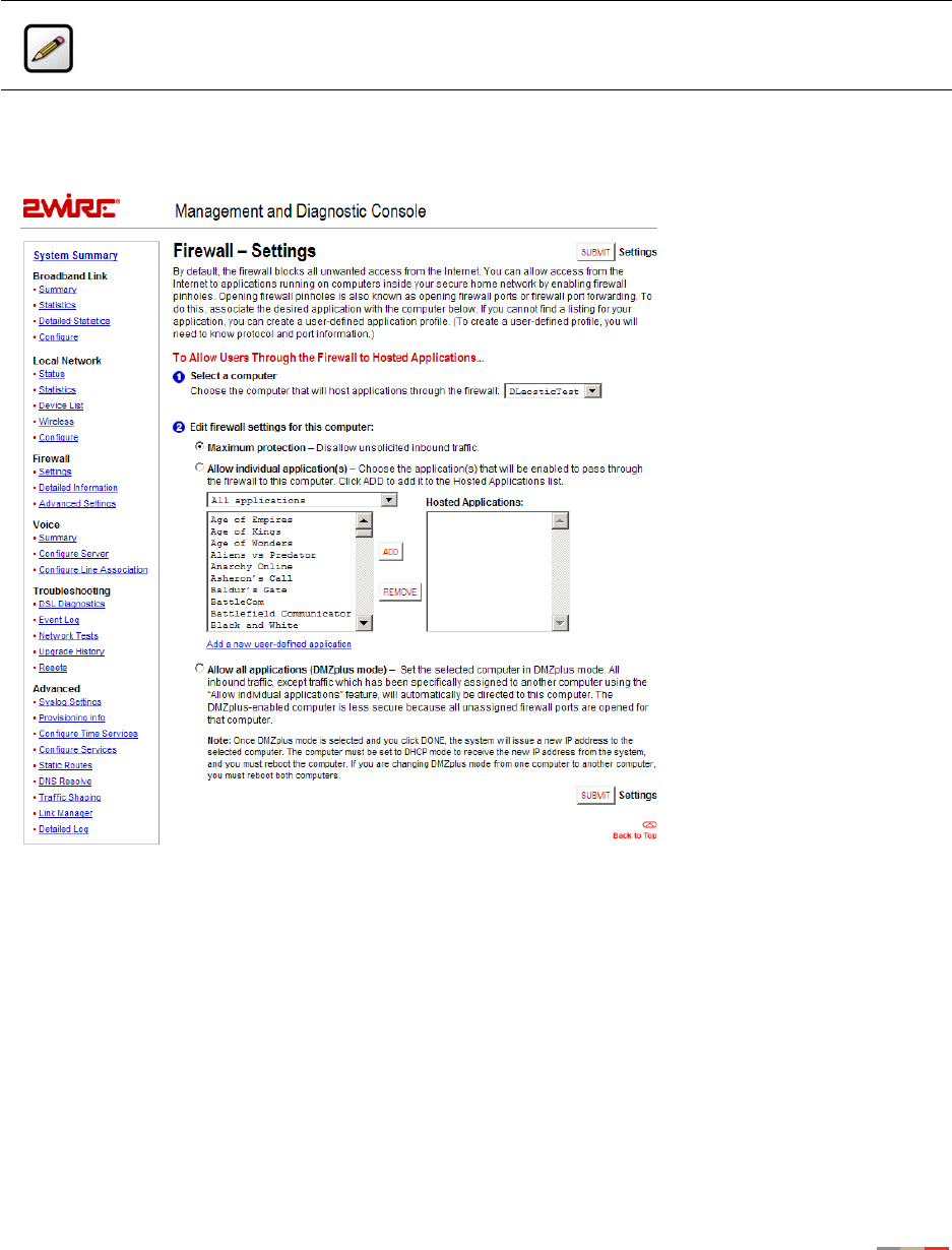
Management and Diagnostic Console
84
Firewall - Settings Page
The Firewall - Settings page allows you to configure the firewall to pass through specific application data to
a selected computer.
Figure 35. MDC Firewall Settings Page
Note: To access this page, your organization must have the Remote Management feature
enabled. If the feature is not enabled, an error message will display when you click the link to
access this page.

Management and Diagnostic Console
85
Hosting an Application
To host an application on the gateway’s network for Internet users to access (such as a Web server), the
firewall must be configured to allow users on the Internet to access it.
To host an application:
1. From 1 Select a computer, select a computer from the pull-down menu.
2. From 2 Edit firewall settings for this computer, click the Allow individual application(s) radio button.
3. From the Applications list, select an application profile.
4. Click the ADD > button. The application displays in the Hosted Applications list.
5. Click the Submit button.
To stop an application that is routed to a selected computer:
1. From the Hosted Applications list, select the application profile name.
2. Click the < REMOVE button.
Creating an Application Profile
If the application that the user wishes to host is not included in the updated application list, you may need
to create an application profile. An application profile configures the system’s firewall to pass through
application-specific data.
Note: If an application does not appear in the Applications list, the list may need updating. If
an update is available, click the UPDATE APPLICATION LIST button.

Management and Diagnostic Console
86
To create an application profile:
1. Click the Add a new user-defined application link. The Edit Application page opens.
Figure 36. MDC Firewall Edit Application Page
2. In the Application Name field, enter a name for the application profile.
3. In the Protocol field, click the TCP or UDP radio button. If both protocols are required, you must create a
definition for each.
4. In the Port (or Range) field, enter the port or port range used by the application.
5. In the Protocol Timeout (seconds) field, enter the amount of time (in seconds) that the connection in
the specified range should remain open when there is no data transfer. In most cases the default value
is appropriate.
6. In the Map to Host Port field, enter the value that provides the mapping offset to the local computer. For
example, if this value is set to 4000 and the range being opened is 100 to 108, the forwarded data to
the first value in the range will be sent to 4000. Subsequent ports will be mapped accordingly; 101 will
be sent to 4001, 102 will be sent to 4002, etc.
7. From the Application Type pull-down menu, select the application type: None (Default), File Transfer
Protocol (FTP), Microsoft Games, H.323-based Internet telephony, IRC (Internet relay chat) server, or
PPTP virtual private network server.
8. Click the Add Definition button.
9. Repeat the previous step for each port or range of ports required for the application profile.

Management and Diagnostic Console
87
Allowing all applications
DMZplus is used for hosting applications if an application will not operate properly using the “Allow
individual application(s)” option. When in DMZplus mode, the designated computer:
• Shares the gateway’s IP address.
• Appears as if it is directly connected to the Internet.
• Has all of the unassigned TCP and UDP ports opened and pointed to it.
• Can receive unsolicited network traffic from the Internet.
To configure a computer on the user’s network for DMZplus mode:
1. Select the computer to which the user wishes to have all data sent.
2. Click the Allow all applications (DMZplus mode) radio button.
3. Click Submit.
4. Access the selected computer.
5. Confirm that the computer is configured for DHCP. If it is not, configure it for DHCP.
6. Restart the computer.
When the computer restarts, it receives a special IP address from the system and all unassigned TCP and
UDP ports are forwarded to it.
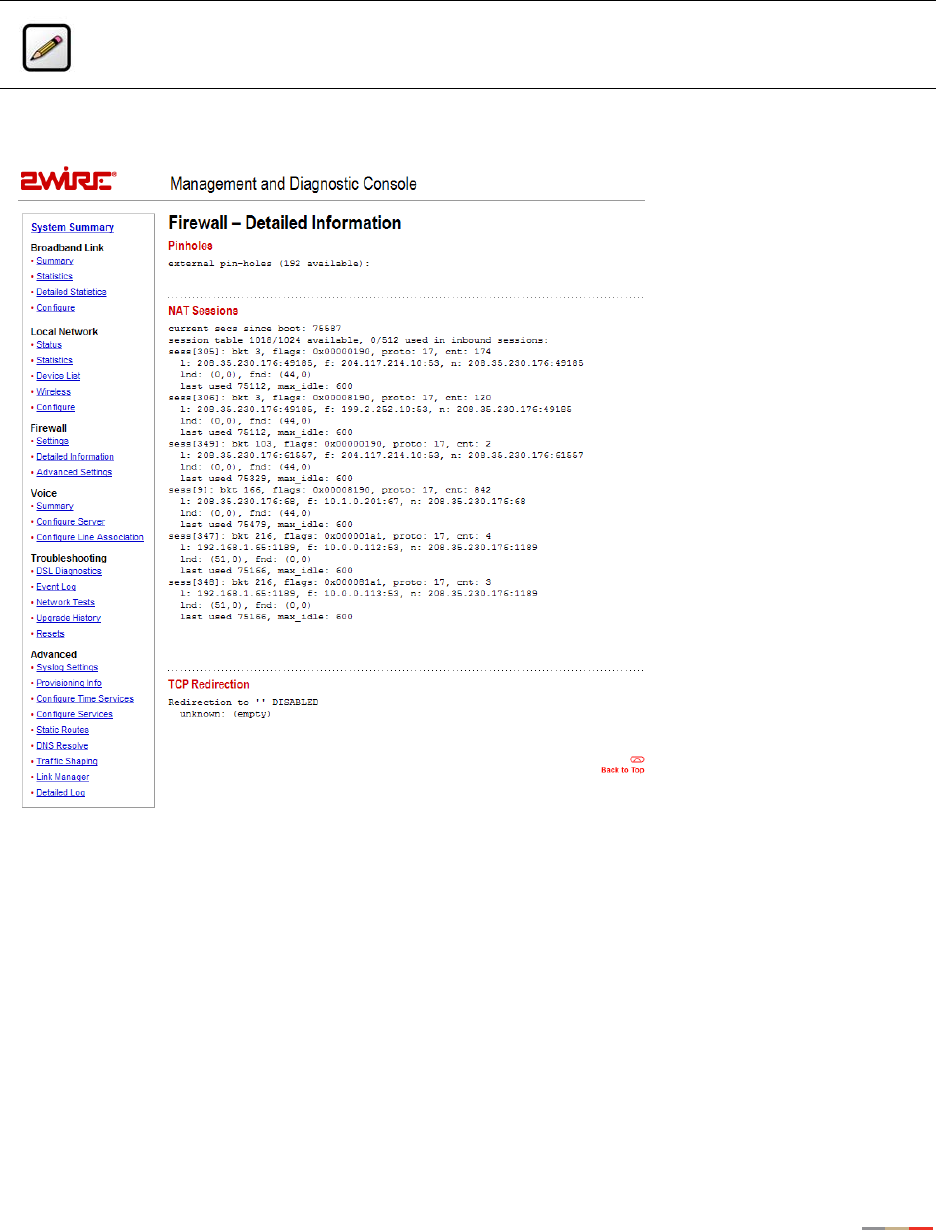
Management and Diagnostic Console
88
Firewall - Detailed Information Page
The Firewall - Detailed Information page shows detailed information about the gateway’s firewall.
Figure 37. MDC Firewall Detailed Information Page
Pinholes
A pinhole is a configuration setting in the firewall that allows access to specific services running on the
network. For example, for users outside the network to access a specific application (such as a game), a
pinhole must be opened on the gateway firewall to allow requests to the application.
The Pinholes pane shows the number of pinholes that are currently open. There are 192 pinholes available.
NAT Sessions
The NAT Sessions pane shows the number of NAT sessions currently running.
Note: To access this page, your organization must have the Remote Management feature
enabled. If the feature is not enabled, an error message will display when you click the link to
access this page.
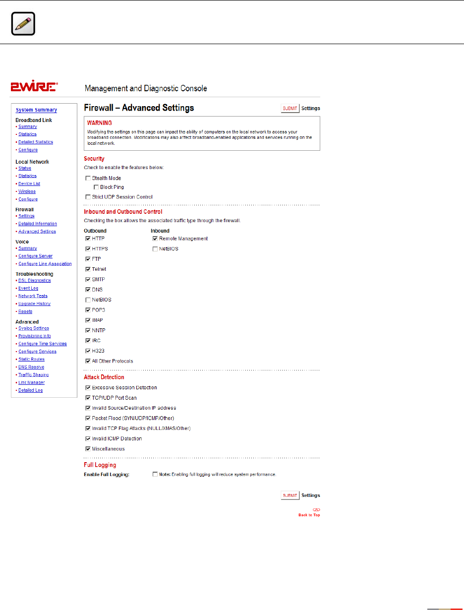
Management and Diagnostic Console
89
Firewall - Advanced Settings Page
The Firewall - Advanced Settings page allows you to configure the gateway’s firewall.
Figure 38. MDC Firewall Advanced Settings Page
Note: To access this page, your organization must have the Remote Management feature
enabled. If the feature is not enabled, an error message will display when you click the link to
access this page.

Management and Diagnostic Console
90
Enabling Security Features
The Security pane allows you to configure the gateway’s firewall to provide additional security features.
Following are descriptions of the features.
Stealth Mode. Enabling Stealth Mode suppresses error responses (for example, TCP resets).
Block Ping. Enabling Block Ping blocks ping responses.
Strict UDP Session Control. Enabling Strict UDP Session Control prevents another source from
“piggybacking” onto a UDP session.
Controlling Inbound and Outbound Traffic
If an Inbound box is checked, the firewall allows the corresponding protocol to pass through from the
Internet to the network. If an Outbound box is checked, the firewall allows the traffic from the network to
pass through the firewall to the Internet. You must click the Submit button for changes to take effect.
Disabling Attack Detection
By default, the 2Wire gateway firewall rules block the attack types listed in the Attack Detection pane. Some
hosted applications require that the user open specific ports (for example, TCP or UDP) to allow outside
users to access their network. The Attack Detection pane allows you to configure the gateway’s firewall
rules to allow traffic through on the specified ports.
To disable attack detection for a specific port, deselect the corresponding checkbox and click the Submit
button.
Enabling Full Logging
To log all packets, check the Enable Full Logging checkbox.
Note: Allowing inbound traffic does not mean that the firewall automatically allows this type of
traffic to pass through the firewall to the network. Even if a particular protocol/application type
is allowed, the firewall still checks and blocks all unsolicited traffic from the Internet unless the
firewall is configured to allow the traffic through using an application profile.
Note: When full logging is enabled, the gateway logs every packet. This will significantly
reduce overall system performance because the log buffer capacity will be reached more
quickly.
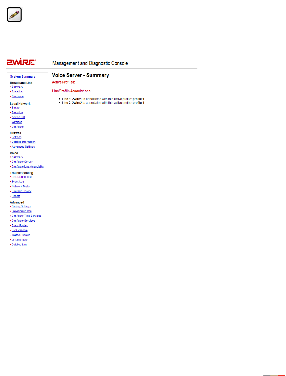
Management and Diagnostic Console
91
Voice Server - Summary Page
The Voice Server - Summary page shows summary information about the voice line(s) and their profile
mappings.
Note: This link is present only if the 2Wire gateway is VoIP-enabled.
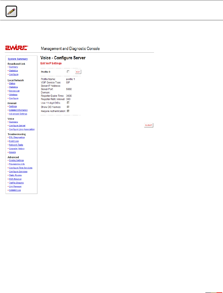
Management and Diagnostic Console
92
Voice - Configure Server Page
The Voice - Configure Server page allows you to edit a profile that is associated with your VoIP services, and
is used primarily for test purposes.
Figure 39. MDC Voice Configure Server Page
Note: This link is present only if the 2Wire gateway is VoIP-enabled.

Management and Diagnostic Console
93
The Edit VoIP Settings panel displays the current SIP settings, and allows you to edit the settings. The
following table describes the fields.
By default, the Show CID Names and Require Authentication checkboxes are checked. Show CID Names allows
the gateway to display the configured outbound caller ID information. Require Authentication allows the
gateway to use authentication when registering with the SIP proxy. Use 11-digit DIDs allows the gateway to
automatically append a “1” to the registration phone number.
1. To add a new profile, choose the VoIP type from the pull-down menu and click ADD. To edit VoIP
settings, click the box next to the profile name and click EDIT. To delete a profile, click the box next to
the profile and click DELETE.
2. If editing a profile, the Edit Profile Settings page opens.
3. Enter a name in the Profile Name field, then enter values in the Server Settings fields as well as the
fields for End Point Settings. Check the appropriate boxes for 11-digit DIDs, CID names, and
authentication.
4. Click SUBMIT.
Server
IP Address Corresponds to the SIP proxy address.
Port Corresponds to the SIP proxy destination port.
Number of Lines Displays the number of lines allowed on the gateway.
End Point
Domain Displays the IP domain of the SIP endpoint.
Register Expire Time Displays the default expiration (in seconds) of the SIP
registration, and indicates how frequently re-registration will
occur.
Register Retry Interval Indicates the period of time (in seconds) before the gateway will
retry registration after a failed attempt.
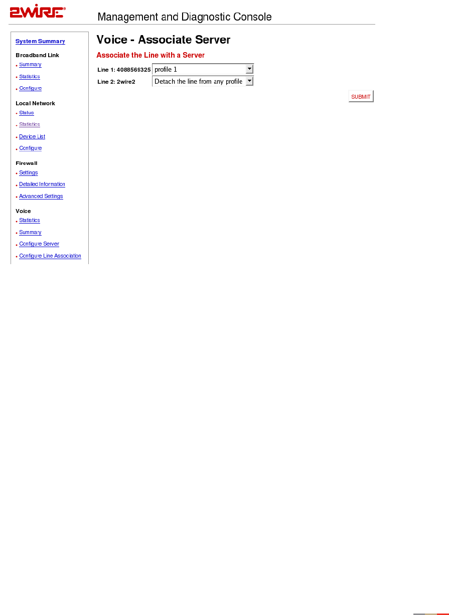
Management and Diagnostic Console
94
5. From the left navigation field under the Voice subheading, click Configure Line Association. The Voice -
Associate Server page opens.
6. Choose a line and associate it with a server from the pull-down menu. If applicable, repeat the process
with another VoIP line. Click SUBMIT.
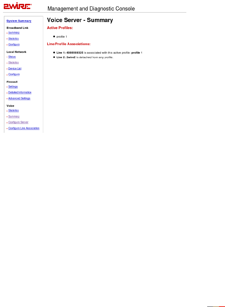
Management and Diagnostic Console
95
7. The Voice Server - Summary page displays. Active profiles are listed, as are Line/Profile associations.
To make any changes, return to the previous step.
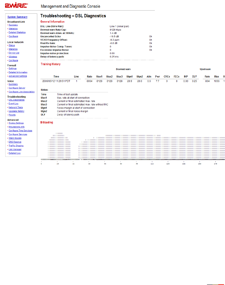
Management and Diagnostic Console
96
Troubleshooting - DSL Diagnostics Page
The Troubleshooting - DSL Diagnostics page displays data associated with the 2Wire gateway’s DSL link.
Figure 40. MDC Troubleshooting DSL Diagnostics Page

Management and Diagnostic Console
97
Analyzing General Information
The General Information pane shows diagnostic information for the current DSL connection (or connection
attempt). These values are also listed in the last row of the Training History pane.
Item Description Value Comment
DSLAM Lists information about the
DSLAM, including country,
DSLAM vendor, and specifics.
DSL Line During line search, the value
will alternate between 1 and
2. The “Searching for DSL
signal” comment appears until
the ADSL protocol is
confirmed with the DSLAM on
the current line.
1 or 2. None or Searching for DSL
signal.
Downstream
Rate Cap
The configured DSL service
downstream speed.
Varies by service
provider.
Downstream
Atten. at 300kHz
The measurement (in kbps) of
the decrease in downstream
signal strength.
Varies by service
provider.
Uncancelled Echo Measure (in dB) of the
uncancelled echo relative to
the background noise on the
line, indicating how much the
uncancelled echo is affecting
DSL performance.
Appropriate values
usually range
between -25dB and
-6dB. A positive
value (for example,
+12) could
indicate the
presence of an
unfiltered
telephony device
and/or an alarm.
Ok or Suspicious - check
phone filters and alarm.
VCXO Frequency
Offset
Indicates the difference
between the gateway’s and the
DSLAM port’s crystal
frequency in parts per million
(ppm).
The ideal value is
zero (0). The
maximum
difference should
be less than 150
ppm.
Ok or Suspicious -
hardware frequency
mismatch.
Final Rx Gain Indicates the current receive
gain setting (in dB).
Dependent on DSL
line length.
Ok or Suspicious -
possible saturation.

Management and Diagnostic Console
98
Reviewing Training History
The Training History pane provides a record of the last 20 connection attempts. The current connection or
connection attempt is displayed in the last row.
Impulse Noise
Comp. Tones
Indicates the number of
compensation tones on which
impulse noise is detected. For
non-interleaved lines with
impulse noise, the connect
rate will be lowered to avoid
excessive errors on the line;
however, impulse noise may
vary with time, so connect
rates may vary accordingly.
Impulse Noise Compensation
is currently disabled for
interleaved lines.
The ideal value is
zero (0).
Ok or Suspicious -
Impulse noise detected.
Excessive
Impulse Noise
Indicates to what degree
impulse noise is present on
the line.
The ideal value is
zero (0).
Impulse noise
protection
Measurement of how much
impulse noise can be
mitigated. Dependent on the
current line configuration.
Delay of latency
path
Measurement of how much
delay is introduced.
Dependent on the current line
configuration.
Item Description
Time Initially this field will display the time (since power on) in DAYS HH:MM:SS format,
until the gateway can access the Internet and retrieve the current local time.
Subsequently the time (since power on) is displayed in YY:MM:DD and HH:MM:SS
format.
Line The line (1 or 2) on which the gateway is searching for a DSL signal.
Downstream
Rate The net user data rate (in kbps) for the connection.
Max 1 Maximum rate achievable at the time of the initial connection based on the line
quality (specifically, the uncapped rate).
Item Description Value Comment

Management and Diagnostic Console
99
Max 2 Latest estimate of maximum achievable rate adjusted for changing line conditions.
Max 3 Current or final estimated maximum achievable rate without impulse noise
compensation.
Mgn 1 Noise margin (in dB) at the start of the connection.
Mgn 2 Latest noise margin adjusted for changing line conditions since the connection was
first established.
Attn Measured attenuation (in dB) of the line.
Pwr Transmit power (in dB).
CRCs Total uncorrected errors for this connection.
FECs Total corrected errors for this connection.
INP Impulse noise protection.
DLY Delay of latency path.
Upstream
Rate The new user data rate (in kbps) for the connection.
Max Maximum rate achievable at the time of the initial connection based on the line
quality (specifically, the uncapped rate).
Mgn Noise margin (in dB) at the start of the connection.
Attn Measured attenuation (in dB) of the line.
Pwr Transmit power (in dB).
CRCs Total uncorrected errors for this connection.
FECs Total corrected errors for this connection.
Mode The DSL mode used (G.DMT, T1.413, or G.LITE).
Vendor Vendor ID of the DSLAM (for example, ALCB indicates Alcatel DSLAM in G.DMT
mode).
State The internal state of the modem. If there are repeated connection problems,
technical support representatives can use this information to determine at what
point during training the modem failed, or whether the modem is repeatedly failing
at the same point.
Item Description

Management and Diagnostic Console
100
Reviewing Bitloading
The Bitloading pane shows the bits loaded per tone for the upstream (tones 6 to 31) and downstream
(tones 32 to 255) spectrum. A single hex-digit for each tone shows the numeric values (0 to F) in addition to
the bar-graph depiction.
Exit Code Indicates the reason for a lost connection or a terminated training attempt.
Following are examples of the typical values that can be represented:
ERR_LOF_LIMIT - Retrained due to loss of framing.
ERR_LOS_LIMIT - Retrained due to loss of signal.
ERR_HI_BER_LIMIT - Retrained due to excessive CRCs.
RESTART - System deliberately restarted modem (line search, reprovisioning, or 30-
second timeout when waiting for DSL signal.
ERR_STATE_TIMEOUT - Modem timed out during training (for example, the modem
failed to detect pilot signal at the appropriate time).
ERR_ALL_OPTIONS_FAIL - Failed to negotiate a final bitrate with DSLAM.
RETRAIN_HIGHER - Proactive retrain in order to obtain a significantly higher connect
rate.
Echo A measure of the uncancelled echo relative to the background noise on the line.
This is an indication of how much the uncancelled echo is affecting DSL
performance, rather than an absolute measure of the uncancelled echo.
VXCO Indicates the difference between the gateway’s and the DSLAM port’s crystal
frequency in parts per million (ppm).
Rx Gain Indicates the current receive gain settings, which will depend on the length of the
DSL line.
INC Tones Indicates the number of compensation tones on which impulse noise is detected.
Item Description
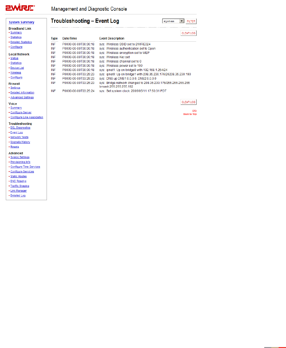
Management and Diagnostic Console
101
Troubleshooting - Event Log Page
The Troubleshooting – Event Log page displays all security related events for the broadband and local
network. Log information is stored in an 8 KB buffer. When the buffer is full, the oldest items are purged
from the log. You can also clear the log contents by clicking the Clear Log button.
Figure 41. MDC Troubleshooting Event Log Page
You can view specific information by selecting which log to view from the pull-down menu and then clicking
the Filter button (the screen capture depicted above has the system filter applied). Following are
descriptions of the logs.
•Access. Shows the current access log, which registers all significant Content Screening and Internet
Access Control events.
•All. Shows all logs that register a significant event (access, firewall, fw alert, system, and wra).
•Firewall. Shows all detailed firewall events, including Internet Access Control and Firewall Monitor.
•FW Alert. Shows the current Firewall Monitor log, which registers all significant Firewall Monitor-related
events.

Management and Diagnostic Console
102
•HURL. Shows the Broadband Redirect messages that have been enabled by a service provider.
•Modem. Shows the current modem log, which registers all significant modem-related events.
•System. Shows the current system log, which registers all significant events within the 2Wire gateway
since it was last restarted.
•WRA. Shows the current Web Remote Access log, which registers all significant Web Remote Access-
related events.
Each log entry includes the severity level, a description of the event, and the actual time that it occurred.
The most recent events display at the bottom of the list.
Events generate an Informational (INF) or Warning (WRN) severity level. Informational indicates events that
are informational only; Warning indicates an unexpected condition that does not affect the 2Wire gateway’s
ability to operate (for example, a network problem or the 2Wire gateway is not configured properly).
For events that involve the transfer of packets, the following additional information is displayed.
Item Description
src Source IP address
dst Destination IP address
ipprot Protocol number as indicated in the IP header field
sport Source port (TCP and UDP)
dport Destination port (TCP and UDP)
Disposition of the event The action taken when the event occurs (for example,
“Unknown inbound session stopped”)
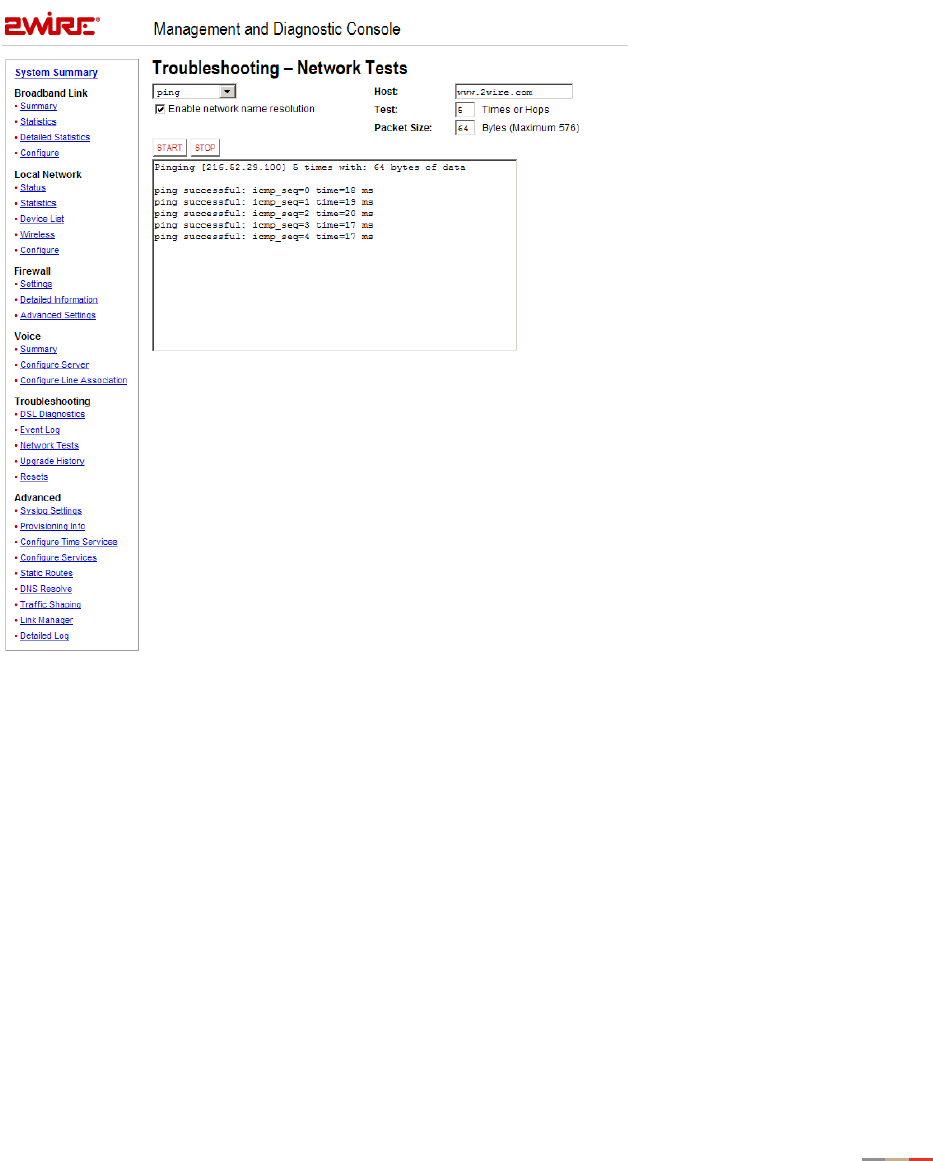
Management and Diagnostic Console
103
Troubleshooting - Network Tests Page
The Troubleshooting – Network Tests page provides the Ping, Traceroute, and DNS Query tools, which help
diagnose problems with the 2Wire gateway or 2Wire gateway connections.
Figure 42. MDC Troubleshooting Network Tests Page
The Ping test allows you to ensure that the 2Wire gateway can send data packets to (ping) a remote host.
The Traceroute test traces the number of times a data packet sent from the 2Wire gateway is routed before
it reaches its destination. The DNS Query test finds the IP address of the domain name service.

Management and Diagnostic Console
104
To perform a ping or traceroute test:
1. From the drop-down menu, select Ping or Traceroute.
2. In the Host field, enter the URL of the host location to which you wish the 2Wire gateway to send the
ping or traceroute.
3. In the Test field, enter the number of times you want the ping to occur (the maximum is 25) or the
number of hops you want traceroute to trace.
4. In the Packet Size field, enter the packet size you wish to send. The maximum packet size is 576.
5. Check the Enable network name resolution checkbox. This will ensure that the name of the host location
is displayed along with the corresponding IP address.
6. Click the Start button.
The results are displayed on the page as they occur, and include round trip latency; the aggregate number of
packets sent, received, and lost; and the minimum, maximum, and average round-trip latency.
To discontinue Ping or Traceroute, click the Stop button.
To perform a DNS query:
1. From the drop-down menu, select DNS Query.
2. In the Host field, enter the domain name (URL) for which you wish to obtain the IP address.
3. Click the Start button.
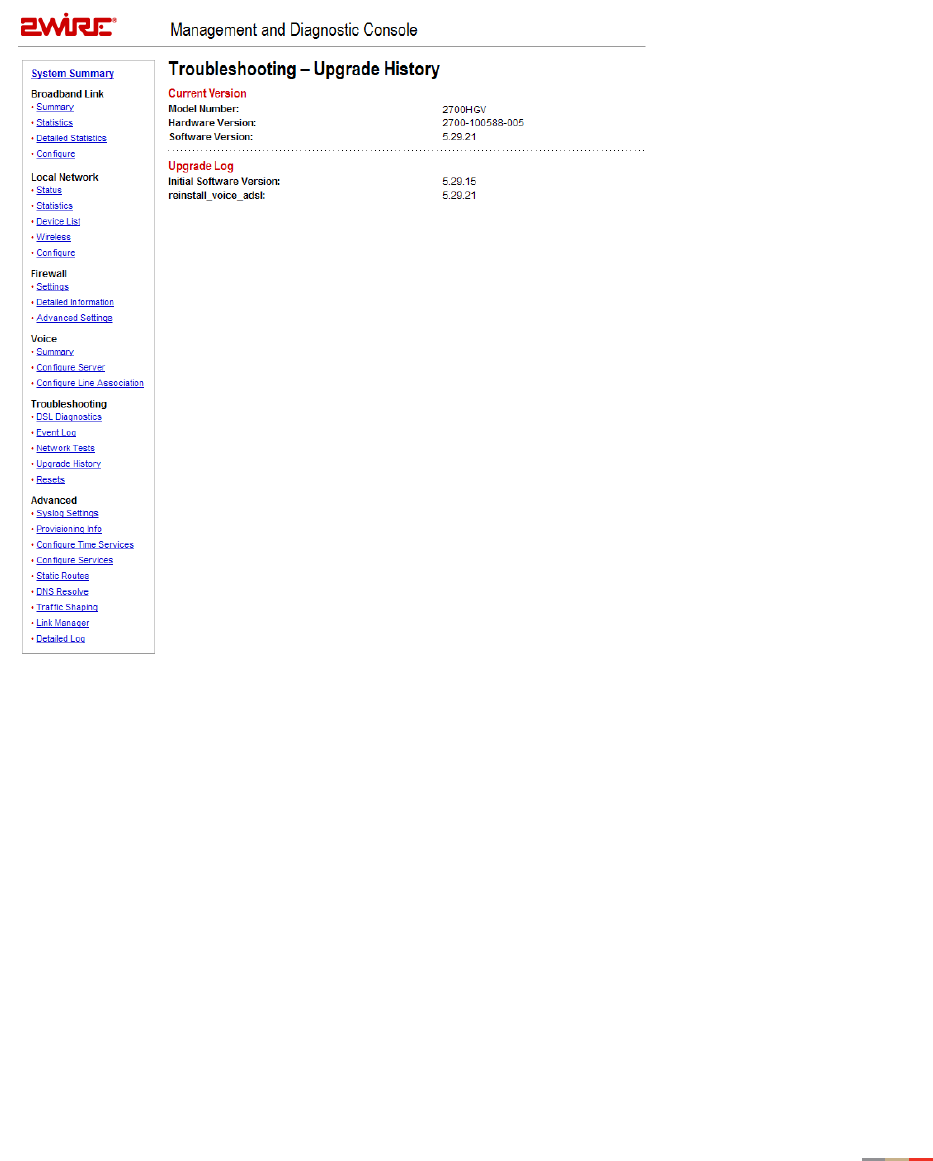
Management and Diagnostic Console
105
Troubleshooting - Upgrade History Page
The Troubleshooting - Upgrade History page shows a log of all system software upgrades, and lists the
upgrades in the order in which they occurred.
Figure 43. MDC Troubleshooting Upgrade History Page
The Upgrade History page shows the following information.
Item Description
Model number The 2Wire gateway model number.
Hardware version The current 2Wire gateway hardware version.
Software version The current 2Wire gateway software version.
Upgrade Log The initial software version, and a record of the last 10
upgrades.
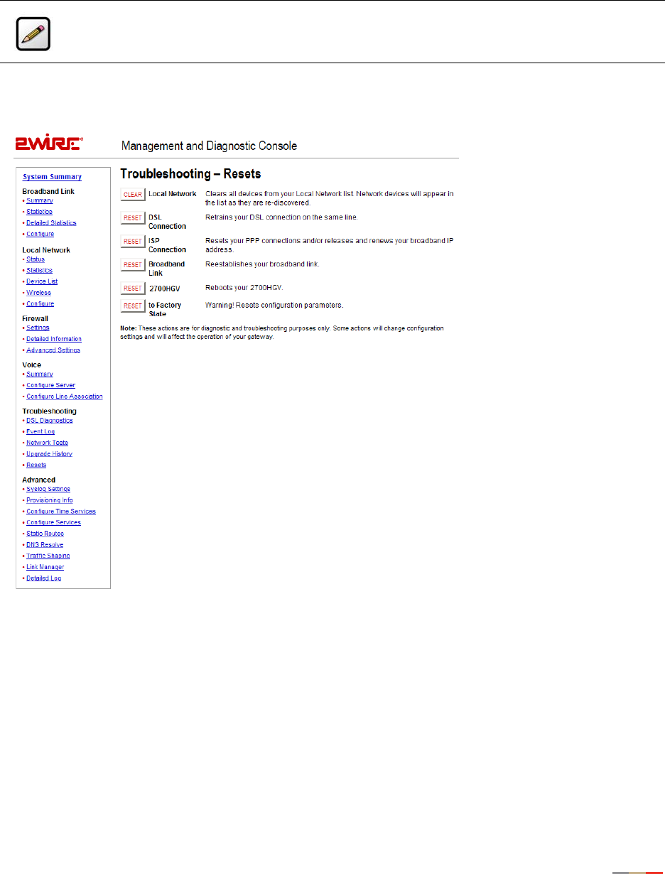
Management and Diagnostic Console
106
Troubleshooting - Resets Page
The Troubleshooting – Resets page allows you to reset various components associated with the 2Wire
gateway network.
Figure 44. MDC Troubleshooting Resets Page
The Clear button in the Local Network field clears all devices from the Local Network list. Doing so will
change the configuration settings, and may affect 2Wire gateway operation because it removes all devices
(such as computers) from your network.
The Reset button in the DSL Connection field retrains the 2Wre gateway’s DSL connection.
The Reset button in the ISP Connection field resets the PPP connection and/or releases and renews the
broadband IP address.
Note: To access this page, your organization must have the Remote Management feature
enabled. If the feature is not enabled, an error message will display when you click the link to
access this page.

Management and Diagnostic Console
107
The Reset button in the Broadband Link field allows you to reset the 2Wire gateway broadband link. For
2Wire gateway models with a DSL connection, this means the DSL connection is reset.
The Reset button in the Gateway field allows you to restart the 2Wire gateway. During 2Wire gateway restart,
the Troubleshooting page cannot be accessed until the 2Wire gateway completely restarts and the
connection is reestablished.
The Reset button in the to Factory State field resets the 2Wire gateway to an unprovisioned default state.
Doing so will remove all your configuration settings, and requires 2Wire gateway software reinstallation.
Warning: Resetting the 2Wire gateway to an unprovisioned default state will clear all update
records from the Upgrade History page, and delete all provisioning, firewall, and Enhanced
Services configuration settings.
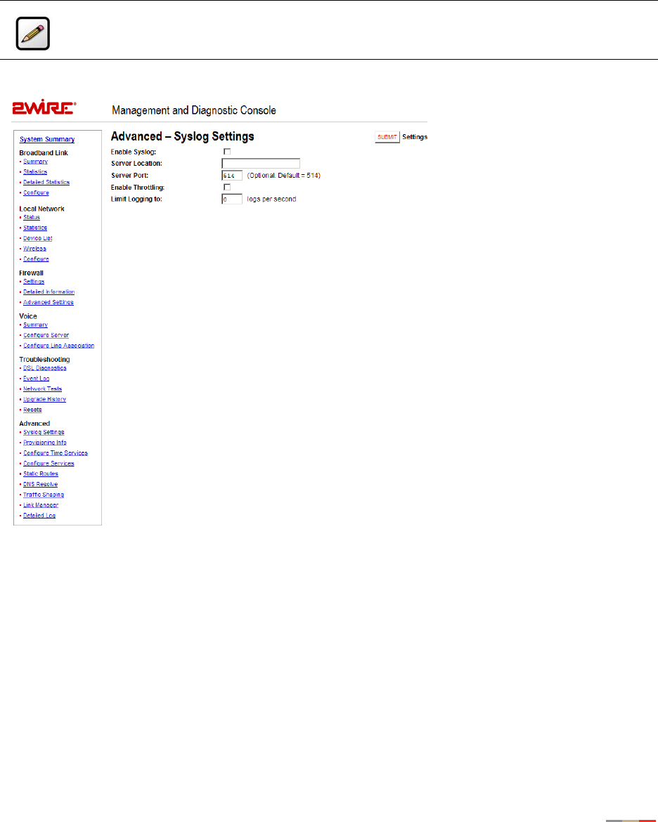
Management and Diagnostic Console
108
Advanced - Syslog Settings Page
The Advanced - Syslog Settings page allows users to maintain a history of security events greater than the
capacity of the 2Wire gateway by enabling a syslog server.
Figure 45. MDC Advanced Syslog Settings Page
To enable syslog and specify the location of a syslog server:
1. Check the Enable Syslog checkbox.
2. In the Server Location field, enter the IP address of a UNIX or Linux computer running a syslog daemon.
3. Optional: In the Server Port field, enter the outbound port number upon which the syslog server is
located.
4. To limit the number of log packets, check the Enable Throttling checkbox.
5. In the Limit Logging to field, enter the number of logs per second that you wish to log.
6. Click the Submit button.
Note: Use of this feature requires a UNIX or Linux computer running a syslog daemon.
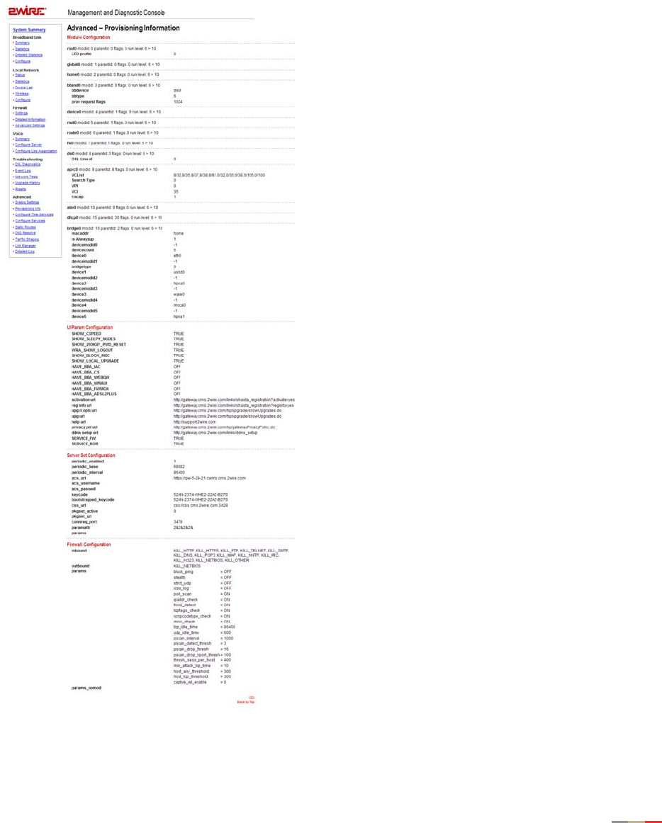
Management and Diagnostic Console
109
Advanced - Provisioning Info Page
The Advanced – Provisioning Info page displays the parameters with which the 2Wire gateway was
provisioned.
Figure 46. MDC Advanced Provisioning Information Page

Management and Diagnostic Console
110
The gateway provisioning parameters are dynamic, and vary depending on the software version that the
gateway is running.
• Module Configuration. Configuration parameters for modules listed in the Advanced Link Manager
States page. The parameters are set by broadband provisioning.
• UI Param Configuration. Configuration parameters that affect the user interface and user interaction.
The parameters are set by broadband provisioning.
• Server Set Configuration. Configuration information defining how the gateway is connected to and
interacts with backend provisioning.
• Firewall Configuration. Configuration information for the firewall.
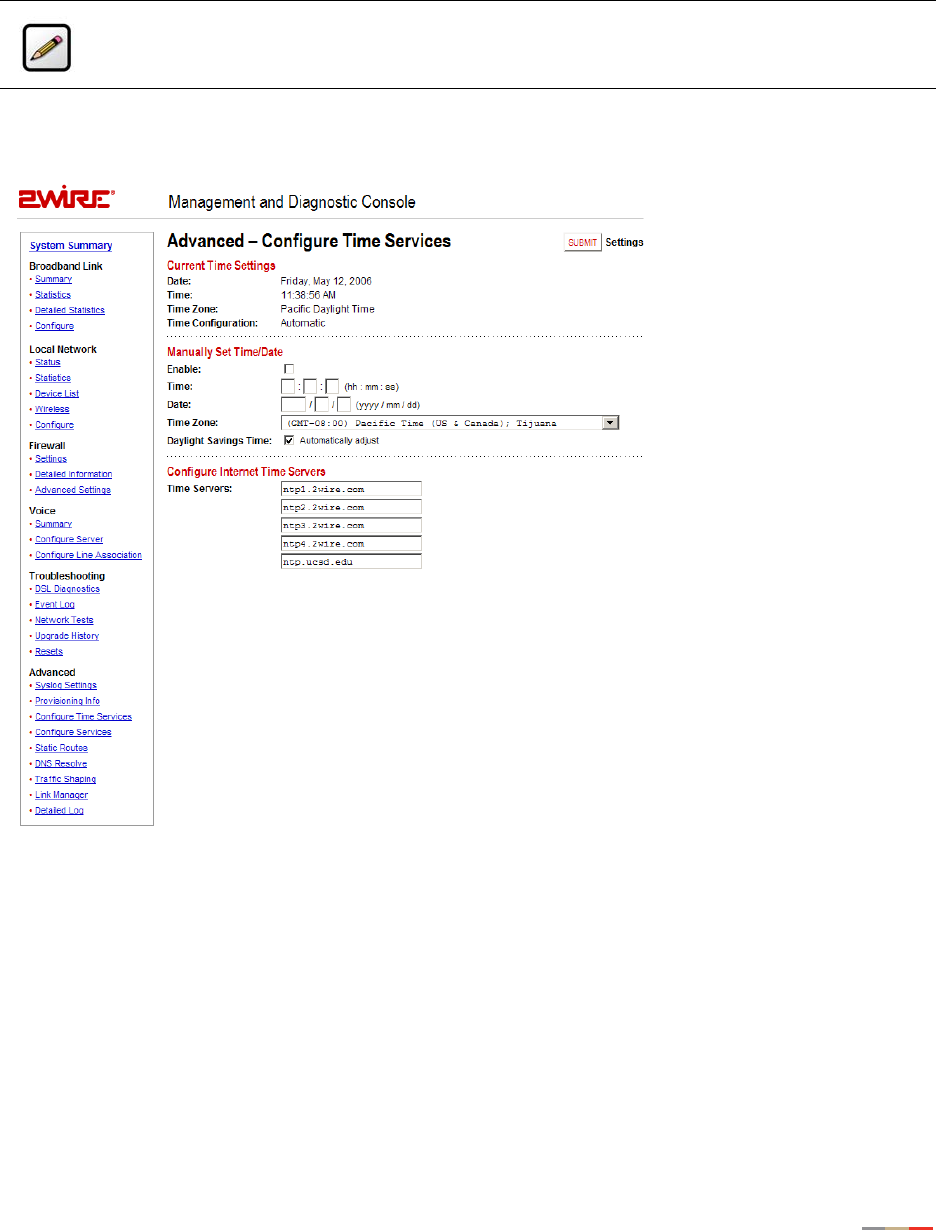
Management and Diagnostic Console
111
Advanced - Configure Time Services Page
The Advanced – Configure Time Services page allows you to view and change system time and date
settings.
Figure 47. MDC Advanced Configure Time Services Page
During the 2Wire gateway setup process, you specify the time zone in which you are located so that the
time and date are automatically displayed in the 2Wire gateway user interface. These time settings are
displayed in the Current Time Settings panel, which shows the current date, time, time zone, and whether
the time was automatically or manually configured. If you wish to manually set the time and date, you can
do so in the Manually Set Time/Date panel.
Note: To access this page, your organization must have the Remote Management feature
enabled. If the feature is not enabled, an error message will display when you click the link to
access this page.

Management and Diagnostic Console
112
To manually set the time and date:
1. Check the Enable checkbox.
2. In the Time field, enter the time in 24-hour HH:MM:SS format (for example, 10:02:11).
3. In the Date field, enter the date in YYYY/MM/DD format (for example, 2006/10/09).
4. From the Time Zone pull-down menu, select the time zone. The available time zones are Hawaii, Alaska,
Pacific, Mountain, Arizona, Central, Eastern, Indiana, and Atlantic (Canada).
5. Check the Daylight Savings Time checkbox if you wish to automatically adjust for daylight savings time.
You can also specify the time servers from which you wish to obtain system time by entering the time server
Internet address in the Time Servers fields. These settings are typically provided by the service provider
and/or backend management system.
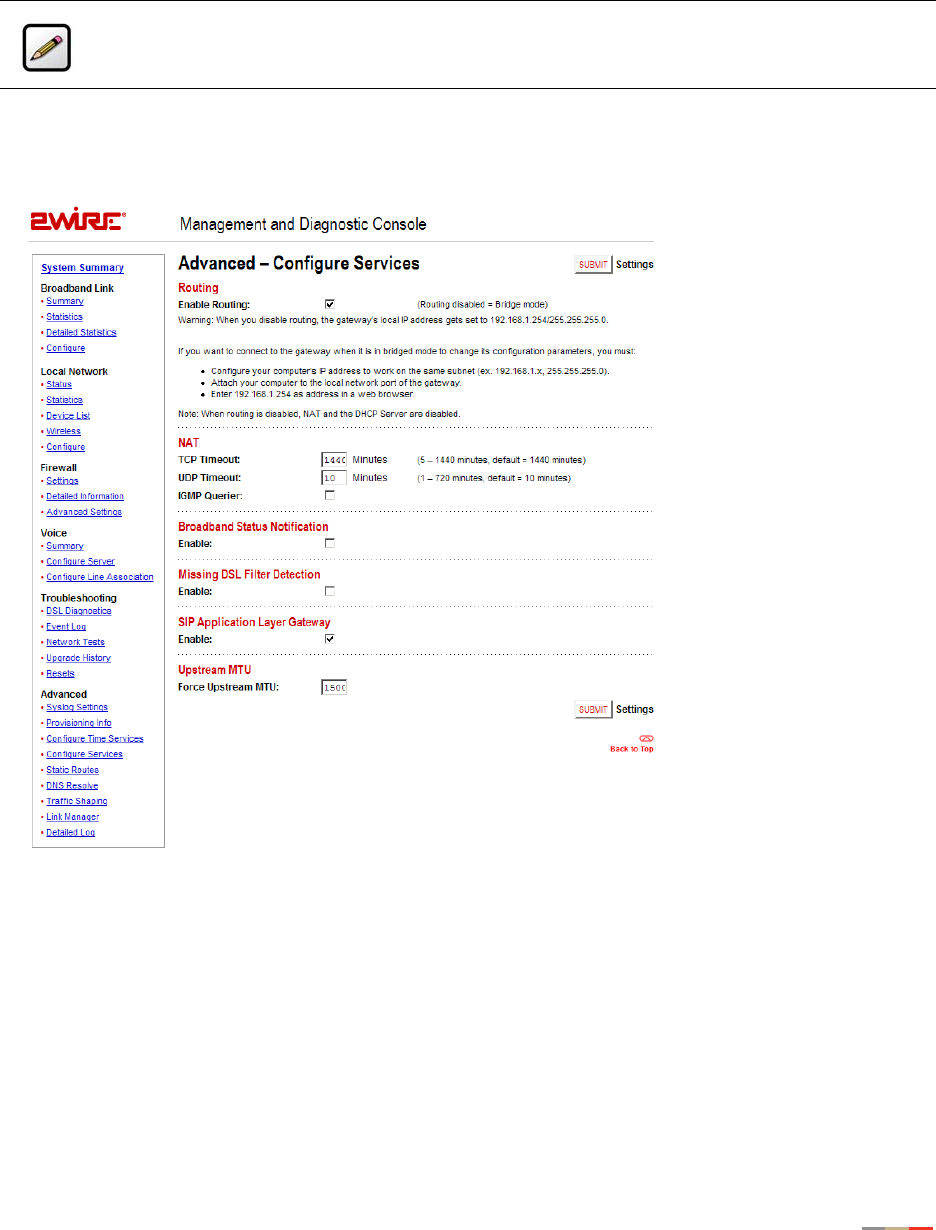
Management and Diagnostic Console
113
Advanced - Configure Services Page
The Advanced – Configure Services page allows you to enable the 2Wire gateway to operate in bridged
mode, change the timeout settings for NAT, enable notification messages, enable the SIP ALG, and change
the upstream maximum transmission rate.
Figure 48. MDC Advanced Configure Services Page
Routing
By default, the 2Wire gateway is configured in routed mode. The Advanced – Configure Services page allows
you to configure the 2Wire gateway to operate in bridged mode.
Note: To access this page, your organization must have the Remote Management feature
enabled. If the feature is not enabled, an error message will display when you click the link to
access this page.
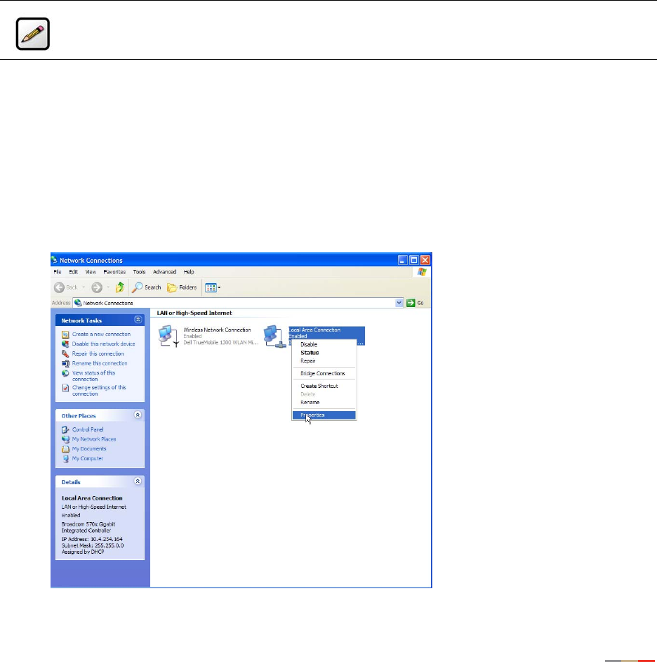
Management and Diagnostic Console
114
IMPORTANT: Bridged mode is intended for testing purposes only, as in WT-062 (ADSL), BER (Bit Rate
Error), or industry standard performance tests. When routed mode is disabled, the 2Wire gateway can no
longer be managed via CMS, and any DSL connection will require an external PPP connection (via software
of third-party hardware). It is strongly recommended that you disable routed mode ONLY if you thoroughly
understand the ramifications of doing so.
To operate the gateway in bridged mode:
1. Deselect the Enable Routing checkbox.
2. Click the Submit button.
Most gateway features are now disabled, including firewall and stateful packet inspection, DHCP, NAT, DNS,
PPP, and remote management. The gateway no longer functions as a gateway and is, in effect, a multi-
protocol (Ethernet, wireless, and USB) bridge.
Computers connected to the 2Wire gateway will retain the IP address assigned by the gateway’s DHCP
server until a new IP address is obtained from an alternative DHCP server, or is manually assigned.
To re-enable routed mode:
1. Configure the computer’s IP address to work on the same subnet as the gateway.
a. From the Windows desktop or the Start menu, right-click the My Network Places icon, then left-click
Properties.
b. Right-click the icon that represents the network connection to the gateway, and
left-click Properties.
Note: When routing is disabled the gateway’s local IP address is set to 172.16.0.1/16.
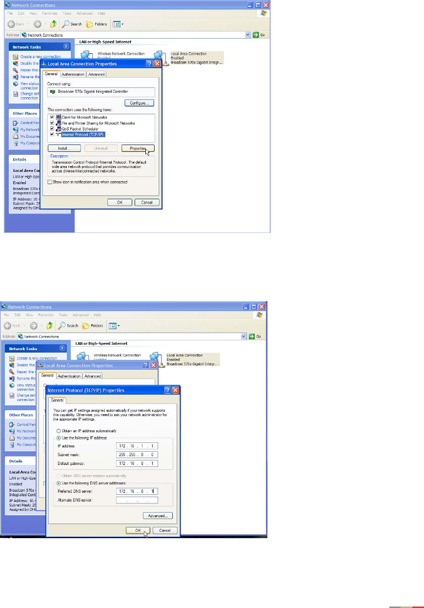
Management and Diagnostic Console
115
c. Click Internet Protocol (TCP/IP), then click the Properties button.
d. In the General tab, click the Use the following IP address radio button.
In the IP address field, enter an IP address between 172.16.1.1 to 172.16.1.32. In the Subnet
mask field, enter 255.255.0.0. In the Default gateway and Preferred DNS server fields, enter
172.16.0.1.
e. Click OK.

Management and Diagnostic Console
116
f. If required, reboot the system for the changes to take effect.
2. Attach the computer to the Local Network port of the 2Wire gateway.
3. In the Web browser address bar, enter 172.16.0.1/management.
4. Click Configure Services.
5. Click the Enable Routing checkbox.
6. Click the Submit Settings button.
The gateway PPP, routing, and TCP/IP functions are now re-enabled, and the Local Network LED will turn
Green. The computer can now be reset to a DHCP-assigned IP address, or left to obtain it statically.
Changing Timeout Parameters
By default, TCP and UDP are configured to timeout in 1,440 and 10 minutes, respectively. You can change
the parameters by entering different values in the TCP Timeout and UDP Timeout fields, and then clicking
the Submit button.
Enabling Broadband Status Notification
To receive a notification message that the gateway has lost broadband connectivity and cannot access the
Internet, check the Enable checkbox.
Enabling Missing DSL Filter Notification
To receive a notification message that the gateway has detected a missing DSL filter, check the Enable
checkbox.
Enabling SIP Application Layer Gateway
To enable the SIP ALG on the gateway firewall, check the Enable checkbox.
Changing the Upstream MTU
The MTU (Maximum Transmission Unit) is the largest size packet or frame, specified in octets (eight-byte
bits), that can be sent from a computer to the network. The 2Wire gateway’s MTU varies, depending on the
connection type used (for example, PPP or direct IP).
Note: This field will display only if the CMS organization has the Broadband Status Notification
feature enabled.
Note: This field will display only if the CMS organization has the Missing DSL Filter Notification
feature enabled.

Management and Diagnostic Console
117
To change the gateway’s upstream MTU:
1. In the Force Upstream MTU field, enter the value specified by the service provider.
2. Click the Submit button.
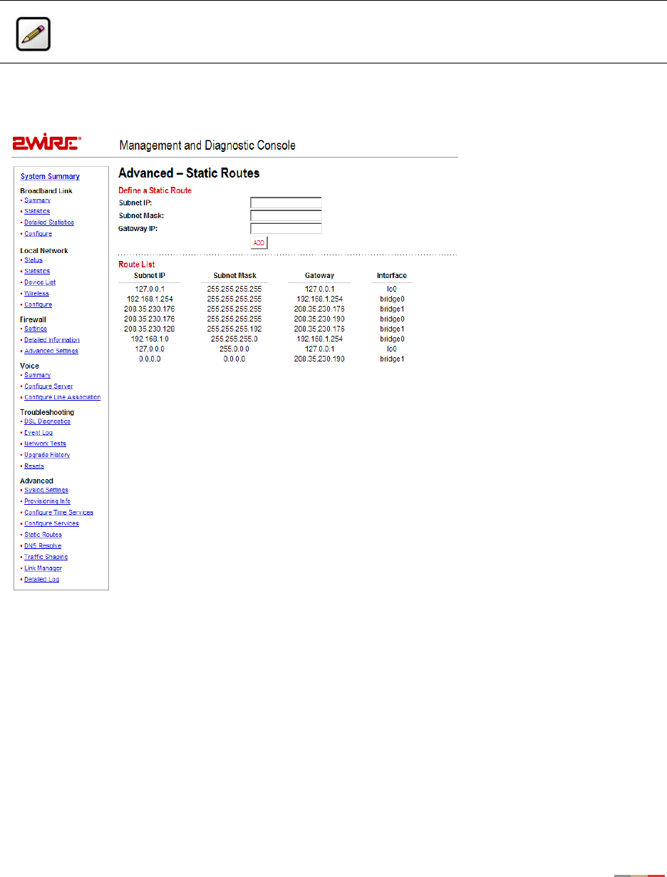
Management and Diagnostic Console
118
Advanced - Static Routes
The Advanced - Static Routes page allows you to manually configure static routes that specify the
transmission path data must follow between devices on the gateway network.
Figure 49. MDC Advanced Static Routes Page
To define a static route:
1. In the Subnet IP field, enter the IP address of the network to which you want to configure a static route.
2. In the Subnet Mask field, enter the subnet mask of the destination network.
3. In the Gateway IP field, enter the IP address of the router for the specified subnet.
4. Click the Add button.
Note: To access this page, your organization must have the Remote Management feature
enabled. If the feature is not enabled, an error message will display when you click the link to
access this page.

Management and Diagnostic Console
119
The Route List shows a list of static routes defined by the user. For each user-defined static route, the
following information is displayed:
• Subnet IP
• Subnet Mask
•Gateway
• Interface
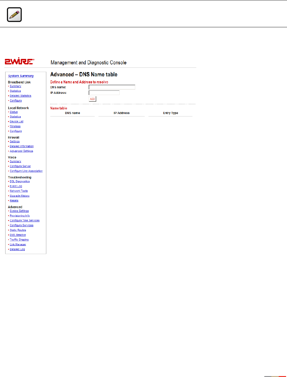
Management and Diagnostic Console
120
Advanced - DNS Resolve Page
The Advanced - DNS Resolve page allows users to name network devices (such as printers or Web servers)
so that they may be easily accessed by other users on the network.
Figure 50. MDC Advanced DNS Name Table Page
To add entries to the Name table:
1. In the DNS name field, enter a name for the device.
2. In the IP Address field, enter the device’s IP address.
3. Click ADD.
4. The Name table displays the name you defined for each device, the device’s IP address, and the entry
type. To remove the device from the Name table, click the Remove button.
Note: To access this page, your organization must have the Remote Management feature
enabled. If the feature is not enabled, an error message will display when you click the link to
access this page.
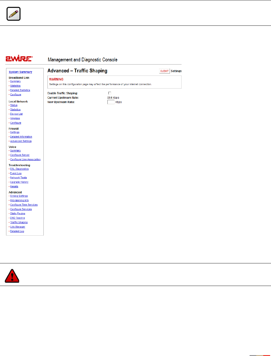
Management and Diagnostic Console
121
Advanced - Traffic Shaping Page
The Advanced - Traffic Shaping page allows users to change the 2Wire gateway’s maximum upstream
connection rate.
Figure 51. MDC Advanced Traffic Shaping Page
To change the gateway’s upstream connection rate:
1. Check the Enable Traffic Shaping checkbox.
2. In the New Upstream Rate field, enter the upstream rate at which you want the gateway to connect.
3. Click the Submit button.
Note: To access this page, your organization must have the Remote Management feature
enabled. If the feature is not enabled, an error message will display when you click the link to
access this page.
Warning: Modifying the gateway’s configuration settings may impede or interrupt the user’s
broadband service, or violate the service provider’s service level agreement.
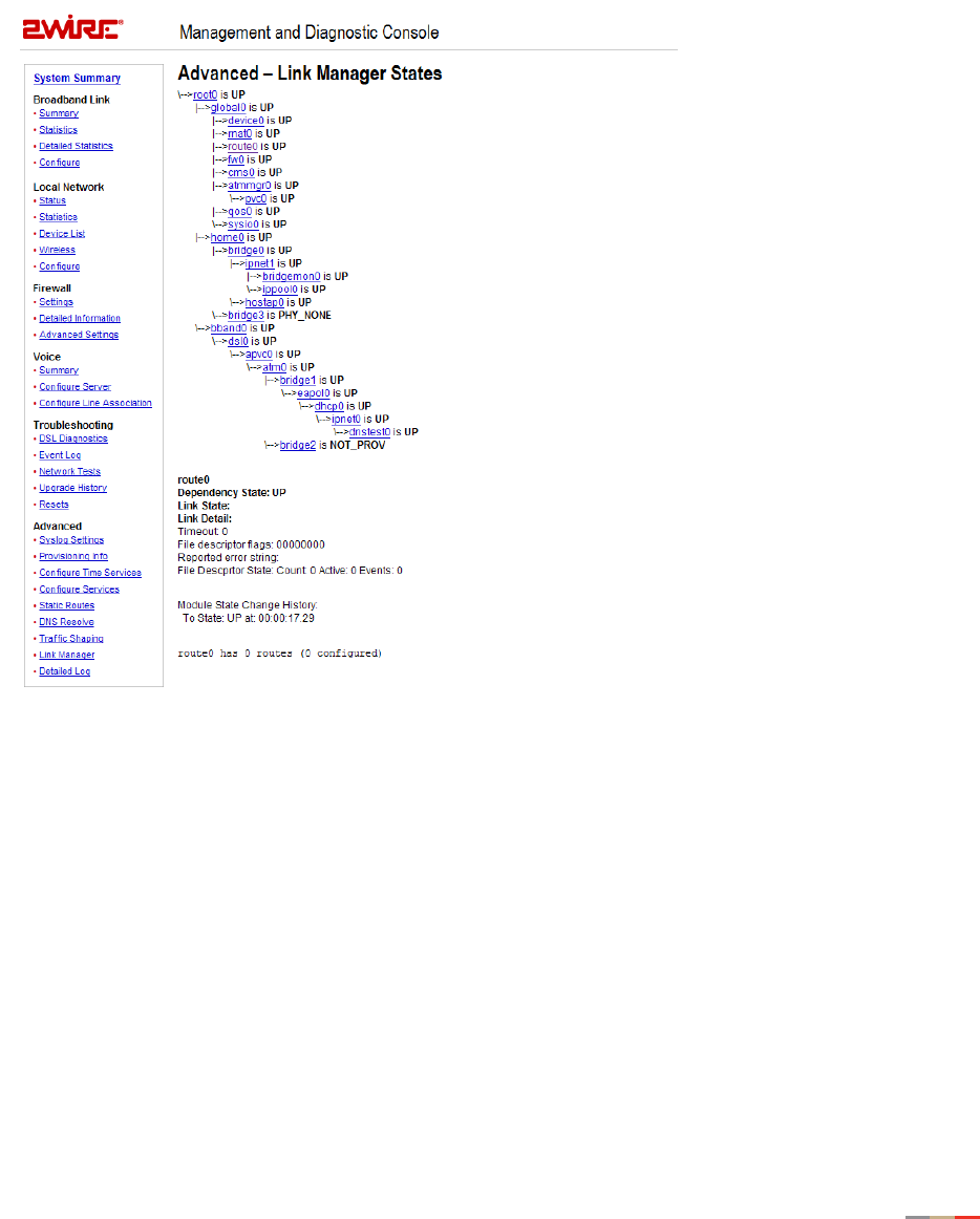
Management and Diagnostic Console
122
Advanced - Link Manager States Page
The Advanced – Link Manager States page is a tree representation of the 2Wire gateway interface stack,
and shows the internal state of the 2Wire gateway.
Figure 52. MDC Advanced Link Manager States Page
The Link Manager States page is used to gather dynamic information on internal networking modules, and
is based on the runtime configuration of the 2Wire gateway. The information cannot be used to configure
the 2Wire gateway.

Management and Diagnostic Console
123
To view information about each node, click the node link. Information displays below the Link Manager
States tree, and includes the following:
Node Information Description
Link status Up. The link is functioning properly.
Climbing. The link is attempting to establish a connection.
Down. The link is not yet configured.
Error. An error has occurred.
State changes The number of times the state of the link has changed (since last
reboot).

Management and Diagnostic Console
124
The following table shows the possible nodes that can display on the Link Manager States page.
The nodes that display are dependent on the 2Wire gateway. For example, 2Wire gateways that are not
connected to the Internet via ADSL will not display ADSL information.
Node Description
root0 Root for configuration tree.
global0 Branch for all global configuration modules.
device0 Maintains the status and configuration for devices on the 2Wire gateway.
rnat0 Maintains the application mappings and pinholes for nodes on the 2Wire gateway.
route0 Maintains all static routes on the 2Wire gateway.
fw0 Maintains all firewall rules on the 2Wire gateway.
cms0 Monitors CMS connectivity and activity with the 2Wire gateway.
home0 Branch for the home network modules.
vlan0 Home network virtual LAN configuration module.
ipnet1 Home network IP configuration module.
vlanmon0 Home network virtual LAN monitor for activity.
ipbridge0 Home network IP bridge/DMZ configuration module.
ipnet2 Home network public IP network configuration module.
vlan3 Home network voice virtual LAN module.
bband0 Branch for the primary broadband network.
vlan1 Primary broadband virtual LAN configuration module.
dhcp0 Primary broadband DHCP client module.
ipnet0 Primary broadband IP configuration module.
dnstest0 Primary broadband DNS access test module.
vlan2 Primary broadband PPP bridge virtual LAN.
dsl0 DSL device control module.
apvc0 Primary broadband ATM and auto PVC search module.
pppoe0 Primary broadband PPPoE configuration module.
pppoa0 Primary broadband PPPoA configuration module.
rtatm0 Primary broadband routed ATM configuration module.
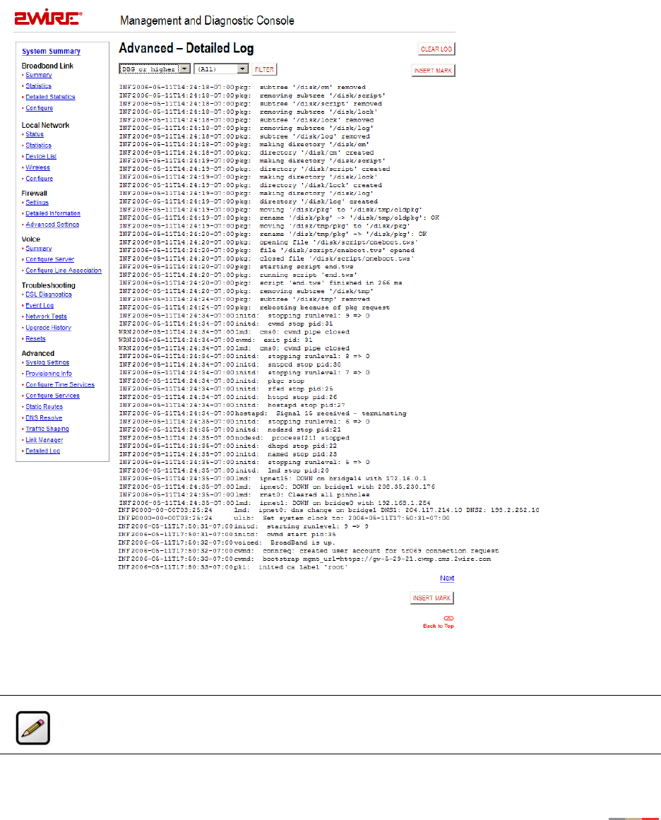
Management and Diagnostic Console
125
Advanced - Detailed Log Page
The Advanced – Detailed Log page is a debug log facility modeled after syslog, and provides advanced
diagnostic capabilities.
Figure 53. MDC Advanced Detailed Log Page
Note: The Detailed Log retains a persistent (across upgrades and system restarts) record of
gateway events.

Management and Diagnostic Console
126
From the Filter pull-down menus, you can select the level of filtering you want to view (for example, DBG or
higher) and the specific gateway component that was affected. Each log displays the following information:
• Status level: DBG (debug), INF (informational), NTC (notice), WRN (warning), ERR (error), FTL (fatal), ALR
(alarm), or EMR (emergency).
• Timestamp (in days, hours, minutes, and seconds) since the state occurred. A “+” preceding the
timestamp designates that the timestamp occurred upon system startup. A time zone (such as “GMT”)
following the timestamp designates that the timestamp occurred after system startup.
• Module in which the state occurred (for example, “netdev”).
• Description of the log entry.
When you click Insert Mark, a “placeholder” is inserted into the code string to mark where the error was
found.
The following table lists the filters that can be applied.
Filter Description
(All) All log messages
aaal5 ATM AAL5 encapsulation
algaim AOL Instant Messenger ALG
algesp IPSec ESP ALG
algh323 H323 ALG
alghttp HTTP ALG
algintt Intoto Wrapper ALG
algmsgame Microsoft Game ALG
algmsn MSN Messenger ALG
algpptp PPTP ALG
algrtp RTP ALG
algrtsp RTSP ALG
algsip SIP ALG
algww Kineto QoS ALG
amon Application monitoring issues
atm ATM stack
cm Configuration Manager/configuration database
devfs Device files system

Management and Diagnostic Console
127
dhcpd DHCP server
dsl DSL modem and DSL control module
dslice DSL hardware
eth Ethernet device
ethatm Ethernet to ATM bridge (1483)
fw Firewall
gpio GPIO (general purpose input/output) device
hostapd Wireless access point daemon
hpna HPNA interface
httpd HTTP daemon
initd Initd daemon logs for application control
ipsess IP firewall session
jtag JTAG device
kacct Kernel accounting
kelog Kernel event log module
kmem Memory
kppp PPP kernel network module
kpppoa PPPoA kernel network module
kpppoe PPPoE kernel network module
krtlock Thread locking
kthread Thread
led LED device
lmd Link Manager daemon logs for module
login Login application
lwdp Lightweight data protocol (VoHPNA)
mdog Hardware watchdog
msig Machine signal-related
named DNS server
Filter Description

Management and Diagnostic Console
128
netdev Network device core
nodesd Network device status daemon
pdump Packet dump (used for debugging)
pkg Package management
pki Public Key Infrastructure subsystem
ppp Point-to-Point Protocol daemon
reset Reset switch driver
rpcd RPCD daemon logs for CMS interaction
rtatm Routed ATM driver
scc Voice SLIC drivers
sip SIP
sntpc Network time client
stream Stream network core
syslog Syslog daemon
system System level
ulib Configuration libraries
usbd USB device
usbhost USB host
vlan Virtual LAN
voh VoHPNA driver
voiced Voice daemon
voip Voice over IP
vr Voice router
vrsip Voice SIP module
wave Wireless device
Filter Description

129
Glossary
A
Access Point. A device that transports data between a wireless network and a wired network. With the help
of the system, a wireless base station is an example of an access point that acts between a wireless node
and with other wired PCs and peripherals.
D
Default Gateway. A device that is placed between network segments (or “subnets”) to ensure that traffic is
properly routed between different subnets. To communicate with a device on another network, users need
to know the default gateway’s IP address.
DHCP (Dynamic Host Configuration Protocol). A TCP/IP protocol that allows servers to assign IP
addresses dynamically to PCs and workstations. The PC or workstation “borrows” the IP address for a
period of time, then the IP address returns to the DHCP server for reassignment.
DMZ (Demilitarized Zone). A computer or small subnetwork that sits between a trusted internal network
(such as a LAN), and an untrusted external network (such as the Internet). Typically, the DMZ contains
devices accessible to Internet traffic, such as Web (HTTP) servers, FTP servers, SMTP (e-mail) servers and
DNS servers.
DNS (Domain Name System). The DNS is the way that Internet domain names (such as www.2wire.com)
are located and translated into IP addresses.
DSLAM (Digital Subscriber Line Access Multiplexer). A device found in telephone company central offices
that takes a number of DSL subscriber lines and concentrates them onto a single ATM line.
E
Ethernet. A type of local area network that operates over twisted wire and cable at speeds of up to 10
Mbps.
I
ICMP (Internet Control Message Protocol). ICMP supports packets containing error, control, and
informational messages. For example, the PING command uses ICMP to test an Internet connection.
Although ICMP is generally harmless, there are some message types that should be dropped. Redirect (5),
Alternate Host Address (6), and Router Advertisement (9) can be used to redirect traffic from your site.
Echo (8), Timestamp (13), and Address Mask Request (17) can be used to obtain information on whether
the host is up, the local time, and the address mask used on your network, respectively. ICMP messages
are also sometimes used as part of DOS attacks (such as flood ping or ping of death).
Invalid TCP flags. Combination of TCP flags (such as SYN/FIN) that signal a malicious attempt to get past
the firewall.
IP (Internet Protocol). The standard signaling method used for all communication over the Internet.

Glossary
130
IP Address. A numeric identifier for your computer. Just as the post office delivers mail to your home
address, servers know to deliver data to your computer based on your IP address. IP addresses can be
dynamic, meaning that your computer “borrows” the IP address for the necessary timeframe, or they can be
fixed, meaning that the number is permanently assigned to your computer.
L
LAN (Local Area Network). A network connecting a number of computers to each other or to a central
server so that the computers can share programs and files.
M
MAC (Media Access Control) Address. A hardware address that has been embedded into the network
interface card (NIC) by its vendor to uniquely identify each node, or point of connection, of a network.
Map to Host Port. When set (not left blank or set to 0), this value provides the mapping offset to the local
computer. For example, if this value is set to 4000 and the range being opened is 100 to 108, the
forwarded data to the first value in the range will be sent to 4000. Subsequent ports will be mapped
accordingly; 101 will be sent to 4001, 102 will be sent to 4002, etc.
MTU (maximum transmission unit). The largest size packet or frame, specified in octets (eight-bit bytes),
that can be sent from a computer to the network. The Internet's TCP uses the MTU to determine the
maximum size of each packet in any transmission. If the MTU is too large, the packet may need to be
retransmitted if it encounters a router that can't handle that large a packet. Too small an MTU size means
relatively more header overhead and more acknowledgements that have to be sent and handled. Most
computer operating systems provide a default MTU value that is suitable for most users. In general,
Internet users should follow the advice of their Internet service provider (ISP) about whether to change the
default value and what to change it to.
N
NAT (Network Address Translation). Enables a LAN to use one set of IP addresses for internal traffic and a
second set of IP addresses for external traffic. This feature is used by the system so an end user can have
an internal computer network in their home, with all its computers using internal IP addresses, using only
one routable IP address, which accesses the outside (Internet).
P
PAT (Port Address Translation). Allows hosts on a LAN to communicate with the rest of a network (such as
the Internet) without revealing their own private IP address. All outbound packets have their IP address
translated to the router’s external IP address. Replies come back to the router, which then translates them
back into the private IP address of the original host for final delivery.
PPP (Point-to-Point Protocol). A protocol that allows a computer to access the Internet using a dial-up
phone line and a high-speed modem. This can be accomplished over Ethernet (PPPoE), or over
Asynchronous Transfer Mode (ATM; PPPoA).

Glossary
131
PPPoA (Point-to-Point Protocol over ATM). A specification for connecting multiple computer users on an
Ethernet LAN to a remote site through common customer premises equipment (such as a modem). PPPoA
combines the Point-to-Point Protocol (PPP), commonly used in dialup connections, with the ATM
(Asynchronous Transfer Mode) protocol, which supports multiple users in a LAN.
PPPoE (Point-to-Point Protocol over Ethernet). A specification for connecting multiple computer users on
an Ethernet LAN to a remote site through common customer premises equipment (such as a modem).
PPPoE combines the Point-to-Point Protocol (PPP), commonly used in dialup connections, with the Ethernet
protocol, which supports multiple users in a LAN.
Protocol Timeout. The amount of time (in seconds) during which a connection in the specified range
remains open when there is no data transfer. After a connection has been established on a given port, the
sender and receiver usually determine when the session is finished and the connection is closed. However,
if the connection is left open and data transfer stops, the system must eventually close the connection and
reclaim the resources in order to protect your network. In some cases, the system might close the
application during normal operation (for example, if there is a long pause between data transfer). If this is
the case, lengthening the timeout may help.
PVC (permanent virtual circuit). A virtual circuit that is permanently available. Used to establish
connections between hosts that communicate frequently.
R
Router. The central switching device in a packet-switched computer network that directs and controls the
flow of data through the network.
S
Subnet Mask. The IP addressing system allows subnetworks or “interchanges” to be created, and devices
numbers or “extensions” to be established within these subnetworks. These numbers are created using a
mathematical device called a subnet mask. A subnet mask, like the IP address, is a set of four numbers in
dotted decimal notation. Subnet masks typically take three forms:
• 255.0.0.0
• 255.255.0.0
• 255.255.255.0
The number 255 “masks” out the corresponding number of the IP address, resulting in IP address numbers
that are valid for the network. For example, an IP address of 123.45.67.89 and a subnet mask of
255.255.255.0 results in a sub network number of 123.45.67.0 and a device number of 89.
The subnet mask used for the network typically corresponds to the class of IP address assigned, as shown
in the following table.
IP Address Class Dotted-Decimal Notation Ranges Corresponding Subnet Mask
Class A 1.xxx.xxx.xxx to 126.xxx.xxx.xxx 255.0.0.0
Class B 128.0.xxx.xxx to 191.255.xxx.xxx 255.255.0.0
Class C 192.0.0.xxx to 223.255.255.xxx 255.255.255.0

Glossary
132
SYN Flood. A method that the user of a hostile client program can use to conduct a denial-of-service (DOS)
attack on a computer server. The hostile client repeatedly sends SYN (synchronization) packets to every
port on the server, using fake IP addresses.
T
TCP/IP (Transmission Control Protocol/Internet Protocol). A method of packet-switched data
transmission used on the Internet. The protocol specifies the manner in which a signal is divided into parts,
as well as the manner in which “address” information is added to each packet to ensure that it reaches its
destination and can be reassembled into the original message.
Transmission Control Protocol/Internet Protocol (TCP/IP). See TCP/IP.
U
UDP (User Datagram Protocol). A TCP/IP protocol describing how data packets reach application programs
within a destination computer.
V
VPI (Virtual Path Identifier). Identifier contained in the ATM cell header to designate the virtual path on the
physical ATM link.
VCI (Virtual Channel Identifier). Identifier contained in the ATM cell header to designate the virtual channel
on the physical ATM link.
W
Wireless. Transmission of data over radio waves rather than wiring.
Wireless channel. The 2Wire gateway supports up to 13 wireless channels (based on country restrictions).
For example, the United States and Canada support channels 1 to 11; Europe and Australia support
channels 1 to 13.
In an 802.1b or 802.11g wireless network, data is transmitted at 2.5GHz. Wireless nodes communicate
with each other using radio frequency signals in the band between 2.4GHz and 2.5GHz. Neighboring
channels are 5 MHz apart; however, due to the spread spectrum effect of the signals, a node sending
signals using a particular channel will use frequency spectrum 12.5HHz above and below the center
channel frequency. As a result, two separate wireless networks using neighboring channels (for example,
channels 1 and 2) in the same general vicinity will interfere with each other. Applying two channels that
allow the maximum channel separation (such as channels 1 and 6, or channels 6 and 11) will provide a
noticeable performance increase over networks with minimal channel separation.
The radio frequency channels used in 802.11b/g networks are shown in the following table.
Channel Range
Channel 1 2399.5 MHz - 2424.5 MHz
Channel 2 2404.5 MHz - 2429.5 MHz

Glossary
133
The preferred channel separation between the channels in neighboring wireless networks is 25 MHz (5
channels). This means that you can apply up to three different channels within your wireless network. There
are only 11 usable wireless channels in the United States. It is recommended that you start using channel
1 and expand to channel 6 (and 11 when necessary), as these three channels do not overlap.
Channel 3 2409.5 MHz - 2434.5 MHz
Channel 4 2414.5 MHz - 2439.5 MHz
Channel 5 2419.5 MHz - 2444.5 MHz
Channel 6 2424.5 MHz - 2449.5 MHz
Channel 7 2429.5 MHz - 2454.5 MHz
Channel 8 2434.5 MHz - 2459.5 MHz
Channel 9 2439.5 MHz - 2464.5 MHz
Channel 10 2444.5 MHz - 2469.5 MHz
Channel 11 2449.5 MHz - 2474.5 MHz
Channel 12 2454.5 MHz - 2479.5 MHz
Channel 13 2459.5 MHz - 2484.5 MHz
Channel Range

134
Regulatory Information
Declaration of Conformity
Trade Name: 2Wire
Responsible Party: 2Wire, Inc.
Address: 1704 Automation Parkway
San Jose, CA
This device complies with Part 15 of the FCC rules. Operation is subject to the following two conditions: (1) This device may not cause
harmful interference, and (2) this device must accept any interference received, including interference that may cause undesired
operation.
This equipment has been tested and found to comply with the limits for a Class B digital device, pursuant to Part 15 of the Rules.
These limits are designed to provide reasonable protection against harmful interference in a residential installation. This equipment
generates, uses, and can radiate radio frequency energy and, if not installed and used in accordance with the instructions, may cause
harmful interference to radio communications. However, there is no guarantee that interference will not occur in a particular
installation. If this equipment does cause harmful interference to radio or television reception, which can be determined by turning the
equipment off and on, the user is encouraged to try to correct the interference by one or more of the following measures:
• Reorient or relocate the receiving antenna.
• Increase the separation between the equipment and the receiver.
• Connect the equipment into an outlet on a circuit different from that to which the receiver is connected.
• Consult the dealer or an experienced radio/TV technician for help.
You are cautioned that any changes or modifications not expressly approved in this manual could void your authority to operate this
equipment.
Only peripherals (computer input/output devices, terminals, printers, and so forth) that comply with FCC Class B limits may be
attached to this computer product.
Operation with noncompliant peripherals is likely to result in interference to radio and television reception.
All cables used to connect peripherals must be shielded and grounded. Operation with cables, connected to peripherals that are not
shielded and grounded may result in interference to radio and television reception.
WARNING: While this device is in operation, a separation distance of at least 20 cm (8 inches) must be maintained between the
radiating antenna inside the ERU and the bodies of all persons exposed to the transmitter in order to meet the FCC RF exposure
guidelines. Making changes to the antenna or the device is not permitted. Doing so may result in the installed system exceeding RF
exposure requirements. This device must not be co-located or operated in conjunction with any other antenna or radio transmitter.
Installers and end users must follow the installation instructions provided in this guide.
FCC Part 68
This equipment complies with Part 68 of the FCC rules. On the bottom of this equipment is a label that contains, among other
information, the FCC equivalence number (REN) for this equipment. If requested, this information must be provided to the telephone
company.
The REN is used to determine the quantity of devices that may be connected to the telephone line. Excessive RENs on the telephone
line may result in the devices not ringing in response to an incoming call. In most, but not all areas, the sum of the RENs should not
exceed five. To be certain of the number of devices that may be connected to the line, as determined by the total RENs, contact the
telephone company to determine the maximum REN for the calling area.
If the terminal equipment causes harm to the telephone network, the telephone company will notify you in advance that temporary
discontinuance of service may be required. But if advance notice is not practical, the telephone company will notify the customer as
soon as possible. Also, you will be advised of your right to file a complaint with the FCC if you believe it is necessary.
The telephone company may make changes in its facilities, equipment, operations or procedures that could affect the operations of
the equipment. If this happens, the telephone company will provide advance notice in order for you to make the necessary
modifications in order to maintain uninterrupted service.
If trouble is experienced with this equipment, please contact the store, reseller, or agent from whom the product was purchased.
Repair of this equipment should be made only by the 2Wire Service Center or a 2Wire authorized agent.
