3 Elite Join MINI02132008 Industrial radio remote controller User Manual

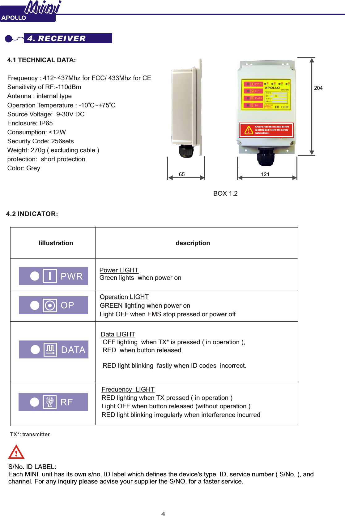
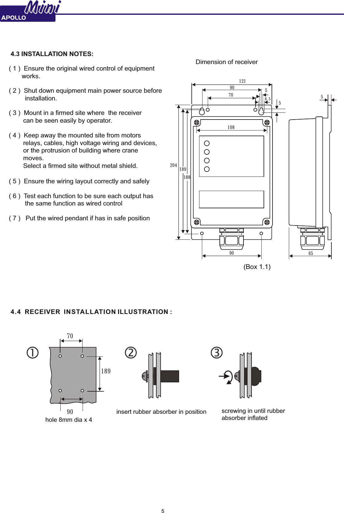
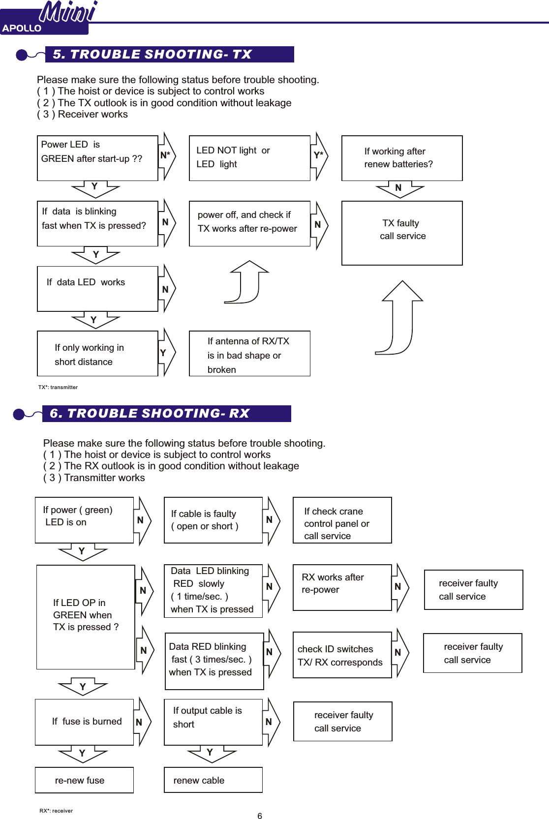
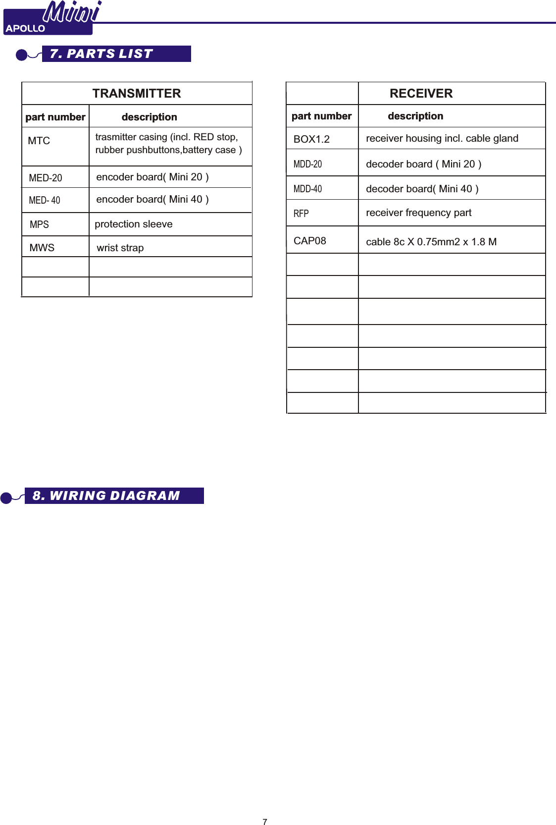
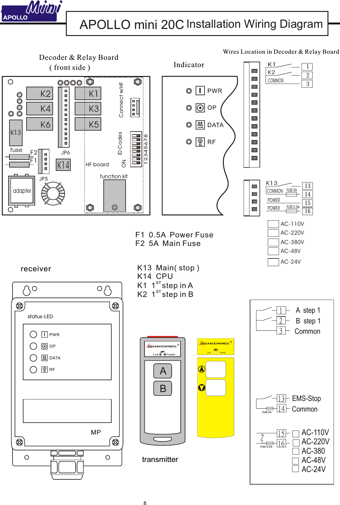
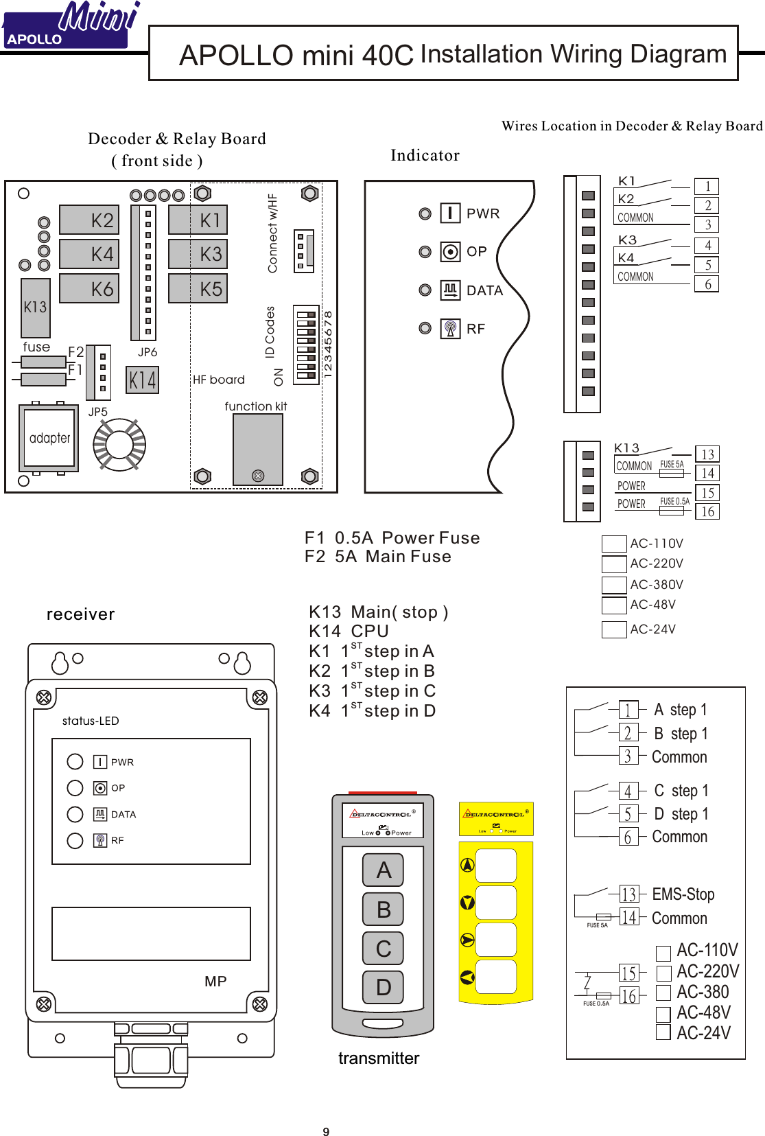
3-Elite Join Industrial Pte Ltd. Industrial radio remote controller

User manual

MiniRADIO REMOTE CONTROLAC versionPlease read the handbook carefully before operation to avoid any dangerous or damage may be incur redDec 2007HANDBOOK
MiniMini                                                TABLE Of CONTENTS1. Introduction ........................................................................................................................2        1.1 Features ...................................................................................................................2        2. Models................................................................................................................................23. Transmitter .........................................................................................................................2         3.1  Technical data. .......................................................................................................2         3.2   Indicator ................................................................................................................3         3.3   Power on steps .....................................................................................................3         3.4   Power off steps .....................................................................................................34. Receiver .............................................................................................................................4         4.1  Technical data. .......................................................................................................4         4.2  Indicator .................................................................................................................4         4.3  Installation notes ....................................................................................................5         4.4  Receiver installation illustration..............................................................................55. Trouble shooting-TX...........................................................................................................66. Trouble shooting-RX ..........................................................................................................67. Parts list .............................................................................................................................78. Wiriing diagram ..................................................................................................................79. Warranty.............................................................................................................................10             INTRODUCTION1
MiniMiniINTRODUCTION( 2)  buttons ( 3)  buttons 1 step, 1 step,          MINI 20MINI30CC              All models are equipped with RED EMS  stop ( push type ) ※1. INTRODUCTION1.1 FEATURES:1. Pocket-size transmitter, light ,more handy for operation.2. ABS +PC transmitter housing, water/shock/dust proof.3. Transmitter 2-4 functions equipped with a push type emergency STOP button .4. Receiver with 4-LED, quick, simple judgement for operation status & after services.INTRODUCTION2. MODELS3.1  TECHNICAL DATA:Operation distance: 100M ( open space )Frequency : FM 412~437Mhz for FCC/ 433Mhz for CE Output power : < 10mWResponse time: 100mSAntenna: internal typeo oTemparature: 0 C~+70 C Source supply:1.5V(AA)*2pcs or rechargable nickel batteryEnclosure: IP65Material: Industrial ABS + PCAddress code : 256 sets                  Weight : 95 g ( excluding batteries )Size: 124x48x25mm3. TRANSMITTER 2u n i t: m m1265029MINI 40C                            1step, (4) buttons
MiniMini3.3 POWER-ON STEPS:   ( 1 )  Power on receiver. ( 2 )  PUSH up the RED stop button to power on the transmitter. ( 3 )  Press any button and release, now MINI is ready to operate          ( now receiver power LED  lights GREEN )POWER-OFF STEPS: ( 1 )   Push down the RED stop button .3.4 CAUTION:Please take out the batteries if long term period NOT operation.3.2 INDICATOR: power off  Indicator lights off  ( EMS OFF )stand-by ( power on )RED/GREEN both indicators  are NOT lighting  ( EMS  ON )operation GREEN indicator light  blinking   power low RED indicator light  blinking ( when button pressed ) Power LEDs/no. label inside of casingEMS stopbattery AA*2function-buttonOFFON
4MiniMini4. RECEIVER 4.1 TECHNICAL DATA:Frequency : 412~437Mhz for FCC/ 433Mhz for CE  Sensitivity of RF:-110dBm                          Antenna : internal type              o oOperation Temperature : -10 C~+75 CSource Voltage:  9-30V DCEnclosure: IP65Consumption: <12WSecurity Code: 256sets Weight: 270g ( excluding cable )protection:  short protectionColor: GreyBOX 1.220412165Frequency  LIGHTRED lighting when TX pressed ( in operation )Light OFF when button released (without operation ) blinking irregularly when interference incurred        RED lightData LIGHT OFF lighting  when TX* is pressed ( in operation ), RED  when button releasedRED light blinking  fastly when ID codes  incorrect.             Operation LIGHTGREEN lighting when power onLight OFF when EMS stop pressed or power off            Power LIGHTGreen lights  when power onIillustrationdescription4.2 INDICATOR:TX*: transmitter        S/No. ID LABEL: Each MINI  unit has its own s/no. ID label which defines the device's type, ID, service number ( S/No. ), and channel. For any inquiry please advise your supplier the S/NO. for a faster service. !Al wa ys r ea d th e ma nual befor eop er t in g an d follow the safe tyin st ructions.
5MiniMini 4.3 INSTALLATION NOTES:( 1 )  Ensure the original wired control of equipment works.( 2 )  Shut down equipment main power source before         installation.( 3 )  Mount in a firmed site where  the receiver         can be seen easily by operator.( 4 )  Keep away the mounted site from motors        relays, cables, high voltage wiring and devices,        or the protrusion of building where crane        moves.        Select a firmed site without metal shield.  ( 5 )  Ensure the wiring layout correctly and safely( 6 )  Test each function to be sure each output has          the same function as wired control( 7 )   Put the wired pendant if has in safe positionDimension of receiver(Box 1.1)20410858.5559012190 657018918870189hole 8mm dia x 4insert rubber absorber in position screwing in until rubberabsorber inflated4.4    INSTALLATION   :RECEIVER  ILLUSTRATION90
6MiniMiniIf power ( green) LED is onRX works after re-powerData  LED  RED  slowly( 1 time/sec. ) when TX is pressedblinkingcheck ID switchesTX/ RX correspondsIf output cable is shortre-new fuse renew cablePower LED  is GREEN after start-up ?? Y*LED NOT light  or LED  lightIf working afterrenew batteries?Please make sure the following status before trouble shooting.( 1 ) The hoist or device is subject to control works( 2 ) The TX outlook is in good condition without leakage( 3 ) Receiver works N* N TX faultycall serviceIf  data  is blinkingfast when TX is pressed? power off, and check ifTX works after re-powerIf  data LED  worksIf only working in short distanceIf antenna of RX/TXis in bad shape orbroken N N Y Y Y6. TROUBLE SHOOTING- RXPlease make sure the following status before trouble shooting.( 1 ) The hoist or device is subject to control works( 2 ) The RX outlook is in good condition without leakage( 3 ) Transmitter worksIf LED OP inGREEN when TX is pressed ?If  fuse is burnedIf cable is faulty( open or short )If check crane control panel or call serviceData RED blinking fast ( 3 times/sec. ) when TX is pressedreceiver faultycall servicereceiver faultycall servicereceiver faultycall service Y N N N N N N N N N N Y Y Y Y5. TROUBLE SHOOTING- TXTX*: transmitterRX*: receiver N
SPARE PARTSTRANSMITTERpart number descriptionMTC trasmitter casing (incl. RED stop, rubber pushbuttons,battery case ) MWS wrist strapBOX1.2 receiver housing incl. cable glandMDD-20decoder board ( Mini 20 )CAP08 cable 8c X 0.75mm2 x 1.8 MMED-20encoder board( Mini 20 )MED- 40encoder board( Mini 40 )MDD-40decoder board( Mini 40 ) MPSprotection sleeve7. PARTS LISTpart number description part number descriptionpart number descriptionRECEIVER8. WIRING DIAGRAMMiniMiniRFPreceiver frequency part7
   APOLLO mini 20C    APOLLOMini  Installation Wiring DiagramMiniMini8ABtransmitter status-LEDreceiver MPK2K14F2F112345678ID CodesHF boardfunction kitConnect w/HFON( front side )fuseadapterAC-110VAC-220VAC-380VAC-48VK4K6K1K3K5K13JP6JP5K13COMMONFUSE 5APOWERPOWER FUSE 0.5A15161314K1K2123COMMONDecoder & Relay Board Wires Location in Decoder & Relay Board IndicatorCommonEMS-Stop AC-110V AC-220V AC-380 AC-48V AC-24VFU SE 5 AFU SE 0 .5 ACommonA  step 1B  step 1AC-24VF1  0.5A  Power FuseF2  5A  Main FuseK13  Main( stop )K14  CPUST K1  1 step in AK2   BST 1 step in
   APOLLO mini 40C   APOLLOMini  Installation Wiring DiagramMiniMini9transmitter receiver status-LEDMPK2K14F2F112345678ID CodesHF boardfunction kitConnect w/HFON( front side )fuseadapterK4K6K1K3K5K13JP6JP5Decoder & Relay Board Wires Location in Decoder & Relay Board  F1  0.5A  Power FuseF2  5A  Main FuseIndicatorACBDCommonA  step 1B  step 1C  step 1D  step 1CommonCommonEMS-StopFU SE 5 AFU SE 0 .5 AK13  Main( stop )K14  CPUST K1  1 step in AK2   BK3   CK4   DST 1 step in ST 1 step in ST 1 step in K13COMMONFUSE 5APOWERPOWER FUSE 0.5A15161314K1K2123COMMONK3K4456COMMON AC-110V AC-220V AC-380 AC-48V AC-24VAC-110VAC-220VAC-380VAC-48VAC-24V9
 WARRANTYThe equipment is warranted for one year from date of purchase against defects in materials or workmanship provided it was purchased from 3-Elite or authorized dealer. This warranty does not cover equipment which has been abused or damaged by careless handling or shipping, OR damaged by nature disaster such as earthquake, typhoon etc.The careless handling including self-change components, antenna, voltage; or circuits, and switches increased would be deemed as end of warranty, user should cover the repairing fee. Should any defect develop, we will, at our option, repair or replace any defective parts without charge for either parts or labour. If we cannot correct the defect in your equipment, we will replace it at no charge with a new one. We will pay for the cost of returning your merchandise to you.This warranty applies only to items returned to us, shipping costs prepaid, within one year from the date of purchase. distributor 10This device complies with part 15 of the FCC rules. Operation is subject to the following two conditions(1)•This device may not cause harmful interference and (2)•This device must accept any interference received, including interference that may cause undesired operation The FCC require the user to be notified that any changes or modifications made to this device that are not expressly approved by 3e may avoid the user’s authority to operate the equipment.To comply with FCC RF exposure requirement, this device and its antenna must no be co-located or operating in conjunction with any other antenna or transmitter.
   STANDARD ACCESSORY tra nsmitt er   x     1  receiver  x    1        handbook  x    1   screw  x     4        tra nsmitt er sleeve  x   2

Navigation menu