3 Elite Join MINI02132008 Industrial radio remote controller User Manual
3-Elite Join Industrial Pte Ltd. Industrial radio remote controller
User manual
Mini
RADIO REMOTE CONTROL
AC version
Please read the handbook carefully before
operation to avoid any dangerous or damage
may be incur red
Dec 2007
HANDBOOK

MiniMini
TABLE Of CONTENTS
1. Introduction ........................................................................................................................2
1.1 Features ...................................................................................................................2
2. Models................................................................................................................................2
3. Transmitter .........................................................................................................................2
3.1 Technical data. .......................................................................................................2
3.2 Indicator ................................................................................................................3
3.3 Power on steps .....................................................................................................3
3.4 Power off steps .....................................................................................................3
4. Receiver .............................................................................................................................4
4.1 Technical data. .......................................................................................................4
4.2 Indicator .................................................................................................................4
4.3 Installation notes ....................................................................................................5
4.4 Receiver installation illustration..............................................................................5
5. Trouble shooting-TX...........................................................................................................6
6. Trouble shooting-RX ..........................................................................................................6
7. Parts list .............................................................................................................................7
8. Wiriing diagram ..................................................................................................................7
9. Warranty.............................................................................................................................10
INTRODUCTION
1
MiniMini
INTRODUCTION
( 2) buttons
( 3) buttons
1 step,
1 step,
MINI 20
MINI30C
C
All models are equipped with RED EMS stop ( push type )
※
1. INTRODUCTION
1.1 FEATURES:
1. Pocket-size transmitter, light ,more handy for operation.
2. ABS +PC transmitter housing, water/shock/dust proof.
3. Transmitter 2-4 functions equipped with a push type emergency STOP button .
4. Receiver with 4-LED, quick, simple judgement for operation status & after services.
INTRODUCTION
2. MODELS
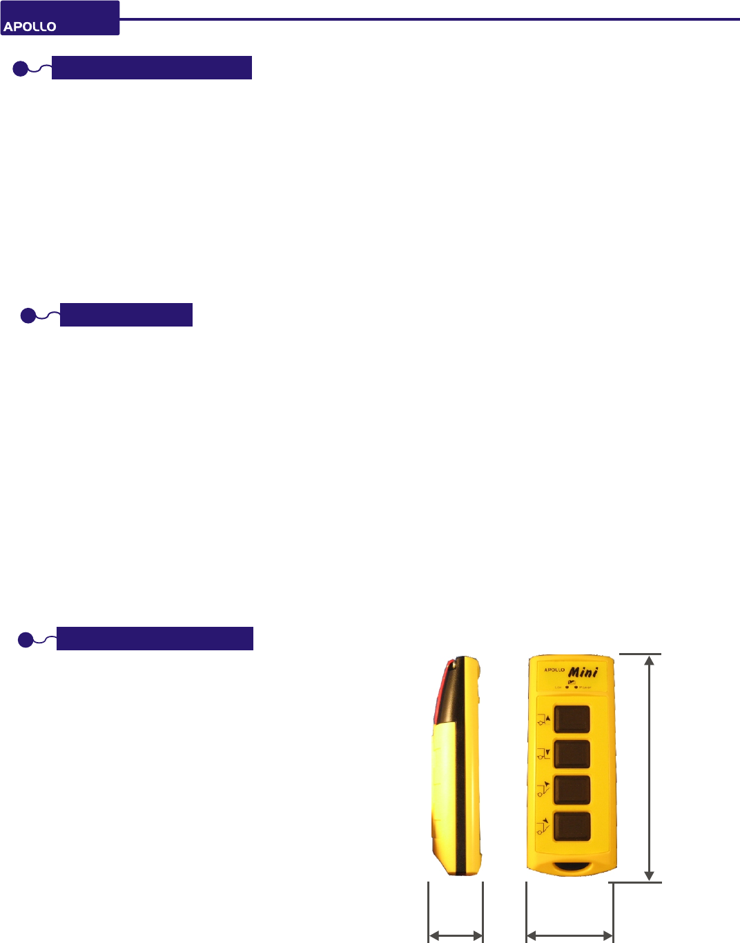
3.1 TECHNICAL DATA:
Operation distance: 100M ( open space )
Frequency : FM 412~437Mhz for FCC/ 433Mhz for CE
Output power : < 10mW
Response time: 100mS
Antenna: internal type
o o
Temparature: 0 C~+70 C
Source supply:1.5V(AA)*2pcs or rechargable nickel battery
Enclosure: IP65
Material: Industrial ABS + PC
Address code : 256 sets
Weight : 95 g ( excluding batteries )
Size: 124x48x25mm
3. TRANSMITTER
2
u n i t: m m
126
5029
MINI 40C 1step, (4) buttons
MiniMini
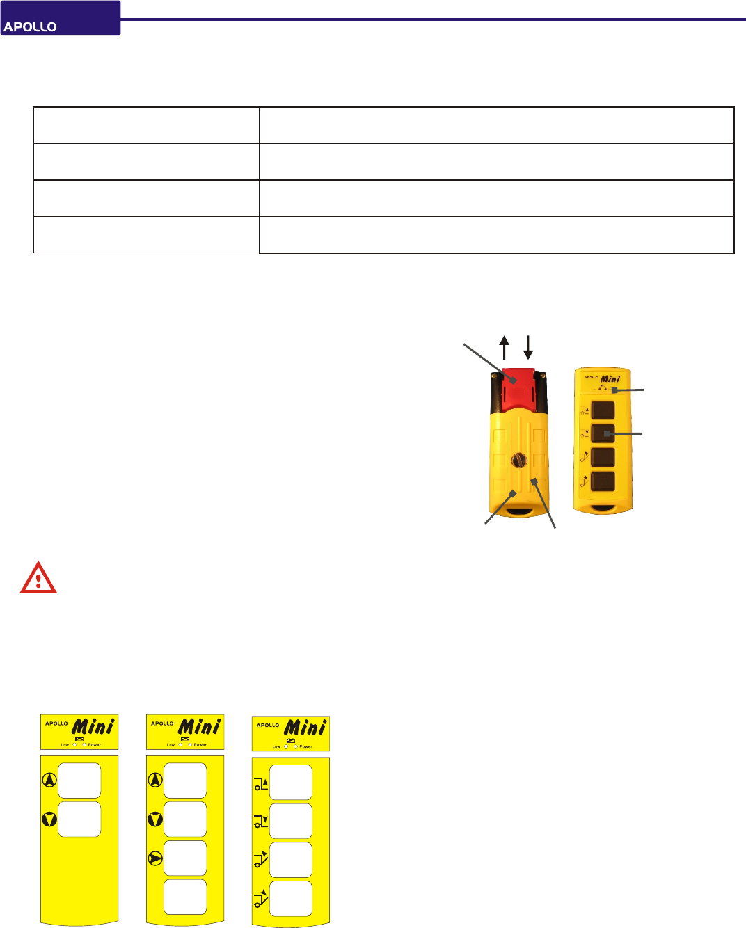
3.3 POWER-ON STEPS:
( 1 ) Power on receiver.
( 2 ) PUSH up the RED stop button to power on the transmitter.
( 3 ) Press any button and release, now MINI is ready to operate
( now receiver power LED lights GREEN )
POWER-OFF STEPS:
( 1 ) Push down the RED stop button .
3.4
CAUTION:
Please take out the batteries if long term period NOT operation.
3.2 INDICATOR:
power off Indicator lights off ( EMS OFF )
stand-by ( power on )
RED/GREEN both indicators are NOT lighting ( EMS ON )
operation GREEN indicator light blinking
power low RED indicator light blinking ( when button pressed )
Power LED
s/no. label
inside of casing
EMS stop
battery AA*2
function-button
OFF
ON
4
MiniMini
4. RECEIVER
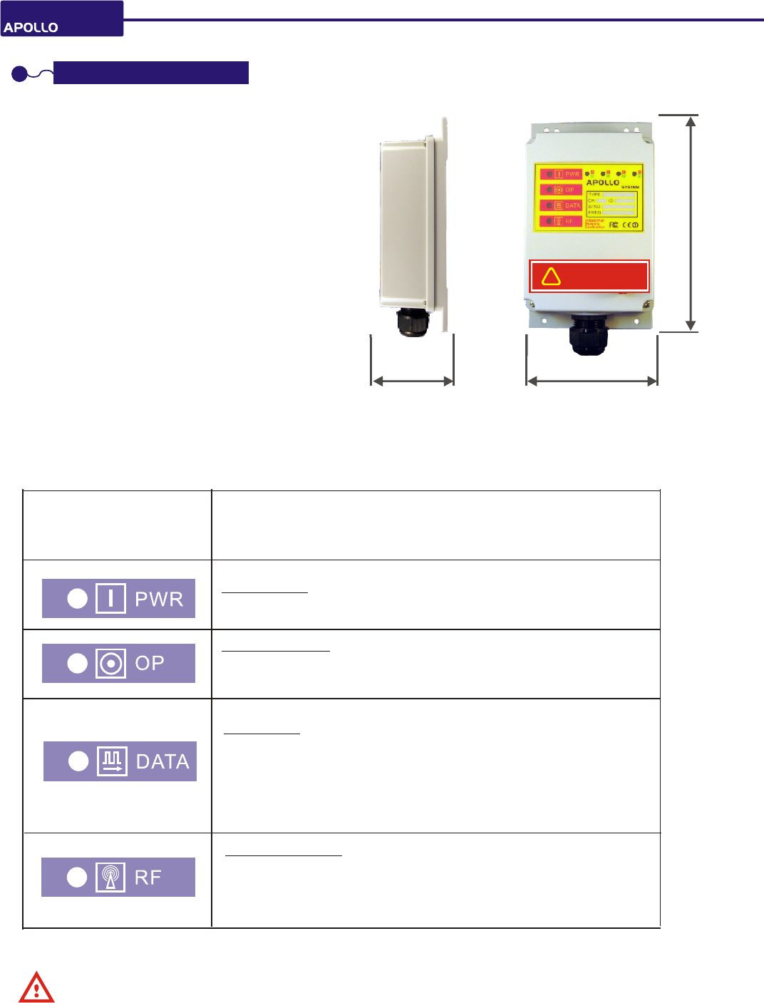
4.1 TECHNICAL DATA:
Frequency : 412~437Mhz for FCC/ 433Mhz for CE
Sensitivity of RF:-110dBm
Antenna : internal type
o o
Operation Temperature : -10 C~+75 C
Source Voltage: 9-30V DC
Enclosure: IP65
Consumption: <12W
Security Code: 256sets
Weight: 270g ( excluding cable )
protection: short protection
Color: Grey
BOX 1.2
204
12165
Frequency LIGHT
RED lighting when TX pressed ( in operation )
Light OFF when button released (without operation )
blinking irregularly when interference incurred
RED light
Data LIGHT
OFF lighting when TX* is pressed ( in operation ),
RED when button released
RED light blinking fastly when ID codes incorrect.
Operation LIGHT
GREEN lighting when power on
Light OFF when EMS stop pressed or power off
Power LIGHT
Green lights when power on
Iillustration
description
4.2 INDICATOR:
TX*: transmitter
S/No. ID LABEL:
Each MINI unit has its own s/no. ID label which defines the device's type, ID, service number ( S/No. ), and
channel. For any inquiry please advise your supplier the S/NO. for a faster service.
!
Al wa ys r ea d th e ma nual befor e
op er t in g an d follow the safe ty
in st ructions.
5
MiniMini
4.3 INSTALLATION NOTES:
( 1 ) Ensure the original wired control of equipment
works.
( 2 ) Shut down equipment main power source before
installation.
( 3 ) Mount in a firmed site where the receiver
can be seen easily by operator.
( 4 ) Keep away the mounted site from motors
relays, cables, high voltage wiring and devices,
or the protrusion of building where crane
moves.
Select a firmed site without metal shield.
( 5 ) Ensure the wiring layout correctly and safely
( 6 ) Test each function to be sure each output has
the same function as wired control
( 7 ) Put the wired pendant if has in safe position
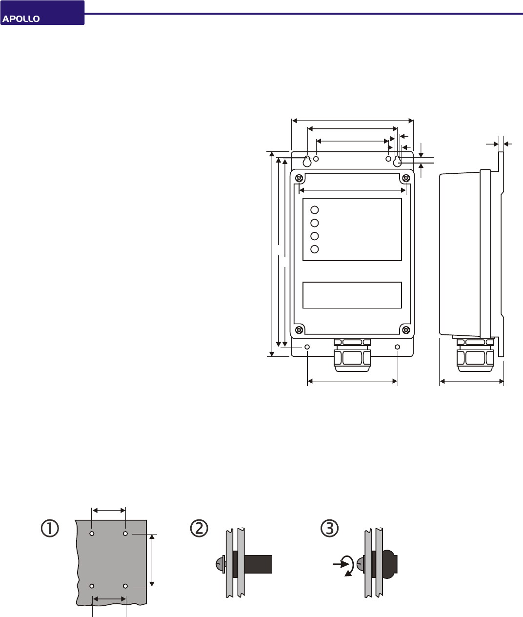
Dimension of receiver
(Box 1.1)
204
108
5
8.5
5
5
90
121
90 65
70
189
188
70
189
hole 8mm dia x 4
insert rubber absorber in position screwing in until rubber
absorber inflated
4.4 INSTALLATION :RECEIVER ILLUSTRATION
90
6
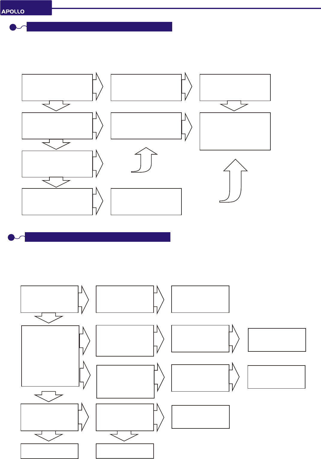
MiniMini
If power ( green)
LED is on
RX works after
re-power
Data LED
RED slowly
( 1 time/sec. )
when TX is pressed
blinking
check ID switches
TX/ RX corresponds
If output cable is
short
re-new fuse renew cable
Power LED is
GREEN after start-up ??
Y*
LED NOT light or
LED light
If working after
renew batteries?
Please make sure the following status before trouble shooting.
( 1 ) The hoist or device is subject to control works
( 2 ) The TX outlook is in good condition without leakage
( 3 ) Receiver works
N*
N
TX faulty
call service
If data is blinking
fast when TX is pressed?
power off, and check if
TX works after re-power
If data LED works
If only working in
short distance
If antenna of RX/TX
is in bad shape or
broken
N
N
Y
Y
Y
6. TROUBLE SHOOTING- RX
Please make sure the following status before trouble shooting.
( 1 ) The hoist or device is subject to control works
( 2 ) The RX outlook is in good condition without leakage
( 3 ) Transmitter works
If LED OP in
GREEN when
TX is pressed ?
If fuse is burned
If cable is faulty
( open or short )
If check crane
control panel or
call service
Data RED blinking
fast ( 3 times/sec. )
when TX is pressed
receiver faulty
call service
receiver faulty
call service
receiver faulty
call service
Y
N N
N N N
N
N
N
N N
Y
Y Y
Y
5. TROUBLE SHOOTING- TX
TX*: transmitter
RX*: receiver
N

SPARE PARTS
TRANSMITTER
part number description
MTC trasmitter casing (incl. RED stop,
rubber pushbuttons,battery case )
MWS wrist strap
BOX1.2 receiver housing incl. cable gland
MDD-20
decoder board ( Mini 20 )
CAP08 cable 8c X 0.75mm2 x 1.8 M
MED-20
encoder board( Mini 20 )
MED- 40
encoder board( Mini 40 )
MDD-40
decoder board( Mini 40 )
MPS
protection sleeve
7. PARTS LIST
part number description part number descriptionpart number description
RECEIVER
8. WIRING DIAGRAM
MiniMini
RFP
receiver frequency part
7
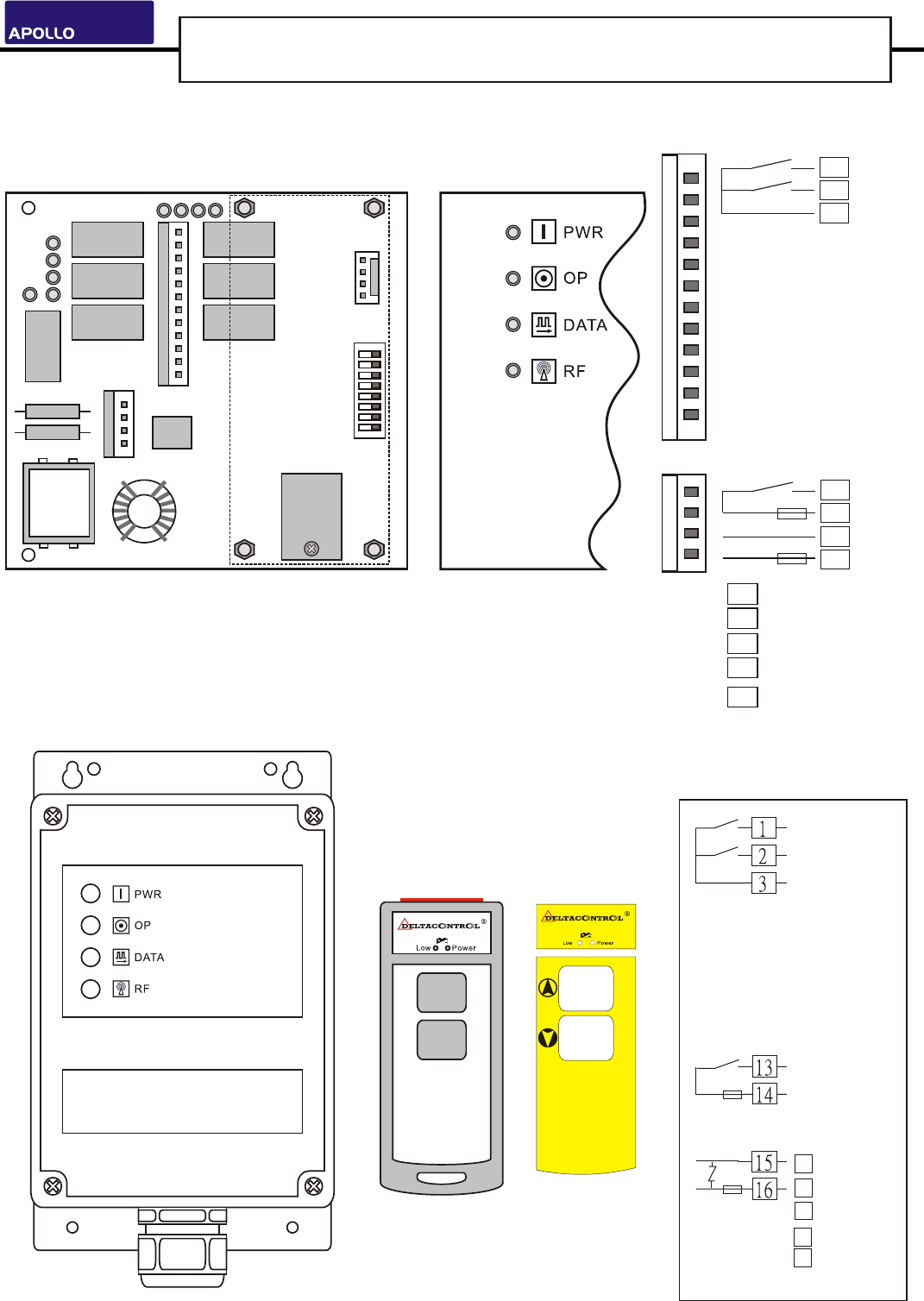
APOLLO mini 20C
APOLLOMini Installation Wiring Diagram
MiniMini
8
A
B
transmitter
status-LED
receiver
MP
K2
K14
F2
F1
12345678
ID Codes
HF board
function kit
Connect w/HF
ON
( front side )
fuse
adapter
AC-110V
AC-220V
AC-380V
AC-48V
K4
K6
K1
K3
K5
K13
JP6
JP5
K13
COMMON
FUSE 5A
POWER
POWER FUSE 0.5A
15
16
13
14
K1
K2
1
2
3
COMMON
Decoder & Relay Board Wires Location in Decoder & Relay Board
Indicator
Common
EMS-Stop
AC-110V
AC-220V
AC-380
AC-48V
AC-24V
FU SE 5 A
FU SE 0 .5 A
Common
A step 1
B step 1
AC-24V
F1 0.5A Power Fuse
F2 5A Main Fuse
K13 Main( stop )
K14 CPU
ST
K1 1 step in A
K2 B
ST
1 step in
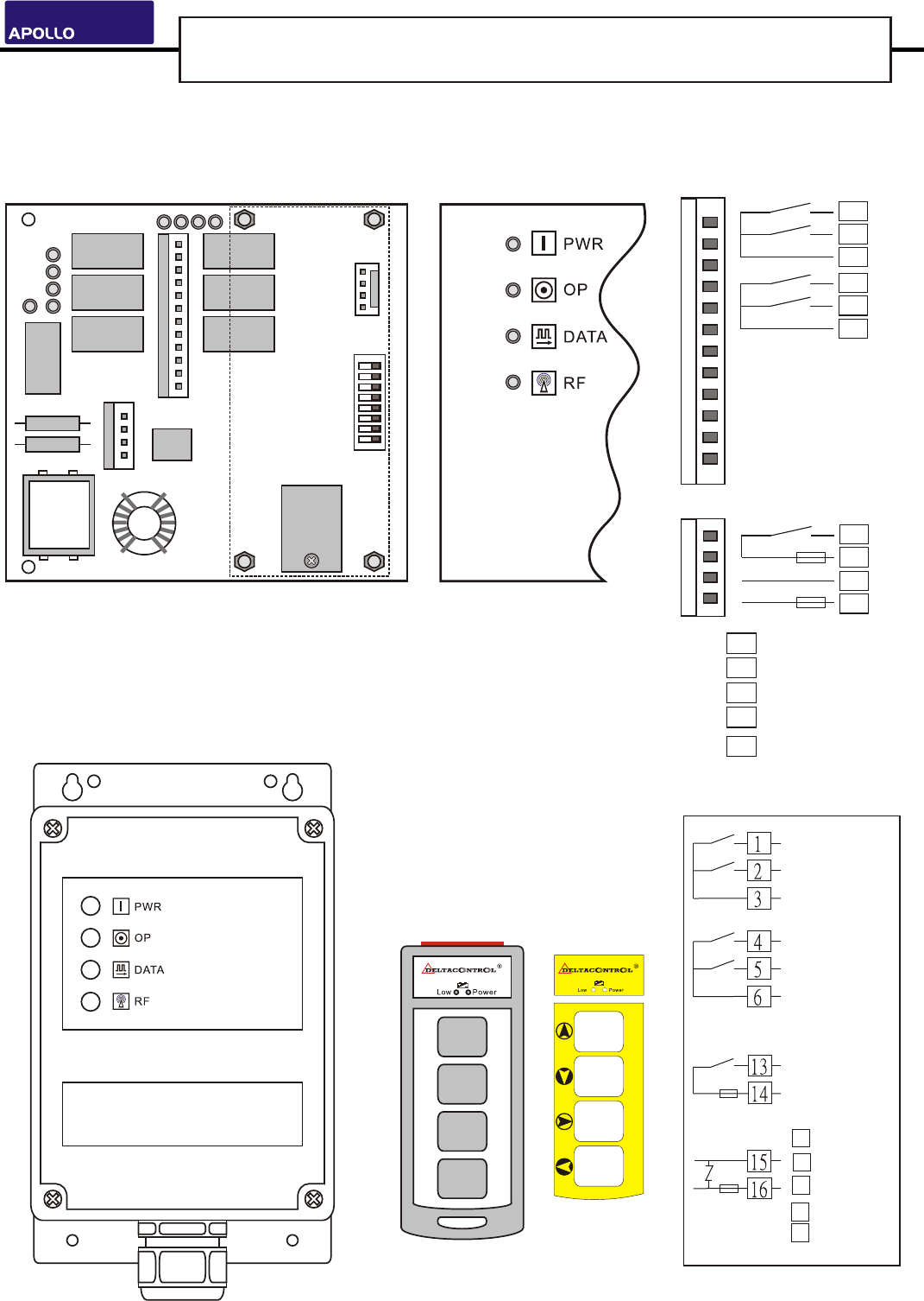
APOLLO mini 40C
APOLLOMini Installation Wiring Diagram
MiniMini
9
transmitter
receiver
status-LED
MP
K2
K14
F2
F1
12345678
ID Codes
HF board
function kit
Connect w/HF
ON
( front side )
fuse
adapter
K4
K6
K1
K3
K5
K13
JP6
JP5
Decoder & Relay Board Wires Location in Decoder & Relay Board
F1 0.5A Power Fuse
F2 5A Main Fuse
Indicator
A
C
B
D
Common
A step 1
B step 1
C step 1
D step 1
Common
Common
EMS-Stop
FU SE 5 A
FU SE 0 .5 A
K13 Main( stop )
K14 CPU
ST
K1 1 step in A
K2 B
K3 C
K4 D
ST
1 step in
ST
1 step in
ST
1 step in
K13
COMMON
FUSE 5A
POWER
POWER FUSE 0.5A
15
16
13
14
K1
K2
1
2
3
COMMON
K3
K4
4
5
6
COMMON
AC-110V
AC-220V
AC-380
AC-48V
AC-24V
AC-110V
AC-220V
AC-380V
AC-48V
AC-24V
9

WARRANTY
The equipment is warranted for one year from date of purchase against defects in materials
or workmanship provided it was purchased from 3-Elite or authorized dealer.
This warranty does not cover equipment which has been abused or damaged by careless
handling or shipping, OR damaged by nature disaster such as earthquake, typhoon etc.
The careless handling including self-change components, antenna, voltage; or circuits, and
switches increased would be deemed as end of warranty, user should cover the repairing
fee.
Should any defect develop, we will, at our option, repair or replace any defective parts
without charge for either parts or labour. If we cannot correct the defect in your equipment,
we will replace it at no charge with a new one. We will pay for the cost of returning your
merchandise to you.
This warranty applies only to items returned to us, shipping costs prepaid, within one year
from the date of purchase.
distributor
10
This device complies with part 15 of the FCC rules. Operation is subject to the following two
conditions
(1)•This device may not cause harmful interference and
(2)•This device must accept any interference received, including interference that may cause
undesired operation
The FCC require the user to be notified that any changes or modifications made to this device that
are not expressly approved by 3e may avoid the user’s authority to operate the equipment.
To comply with FCC RF exposure requirement, this device and its antenna must no be co-located or
operating in conjunction with any other antenna or transmitter.

STANDARD ACCESSORY
tra nsmitt er x 1 receiver x 1 handbook x 1
screw x 4 tra nsmitt er sleeve x 2