305 BROADCAST ETG150IS FM Broadcast Transmitter User Manual 1
305 BROADCAST, LLC FM Broadcast Transmitter 1
UserManual.wiki
>
305 BROADCAST
>
ETG150IS User Manual
>
User Manual 1
Contents
1.
User Manual 1
2.
User Manual 2
User Manual 1
Navigation menu
Upload a User Manual
Namespaces
Wiki Guide
HTML
PDF
Info
Views
User Manual
Discussion / Help
Navigation
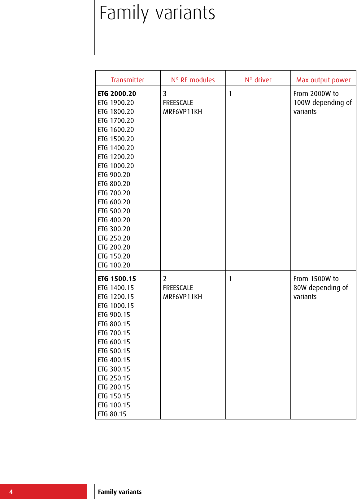
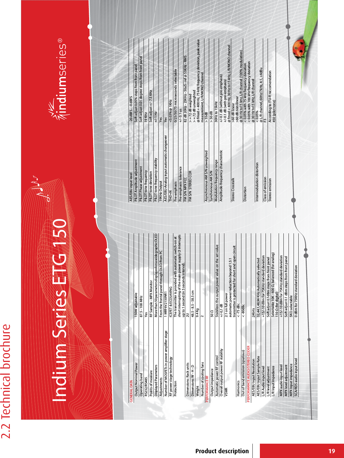
![11[4][8][7] [5][1][6][2][3][9]2 Product descriptionProduct description](https://usermanual.wiki/305-BROADCAST/ETG150IS.User-Manual-1/User-Guide-2906740-Page-13.png)
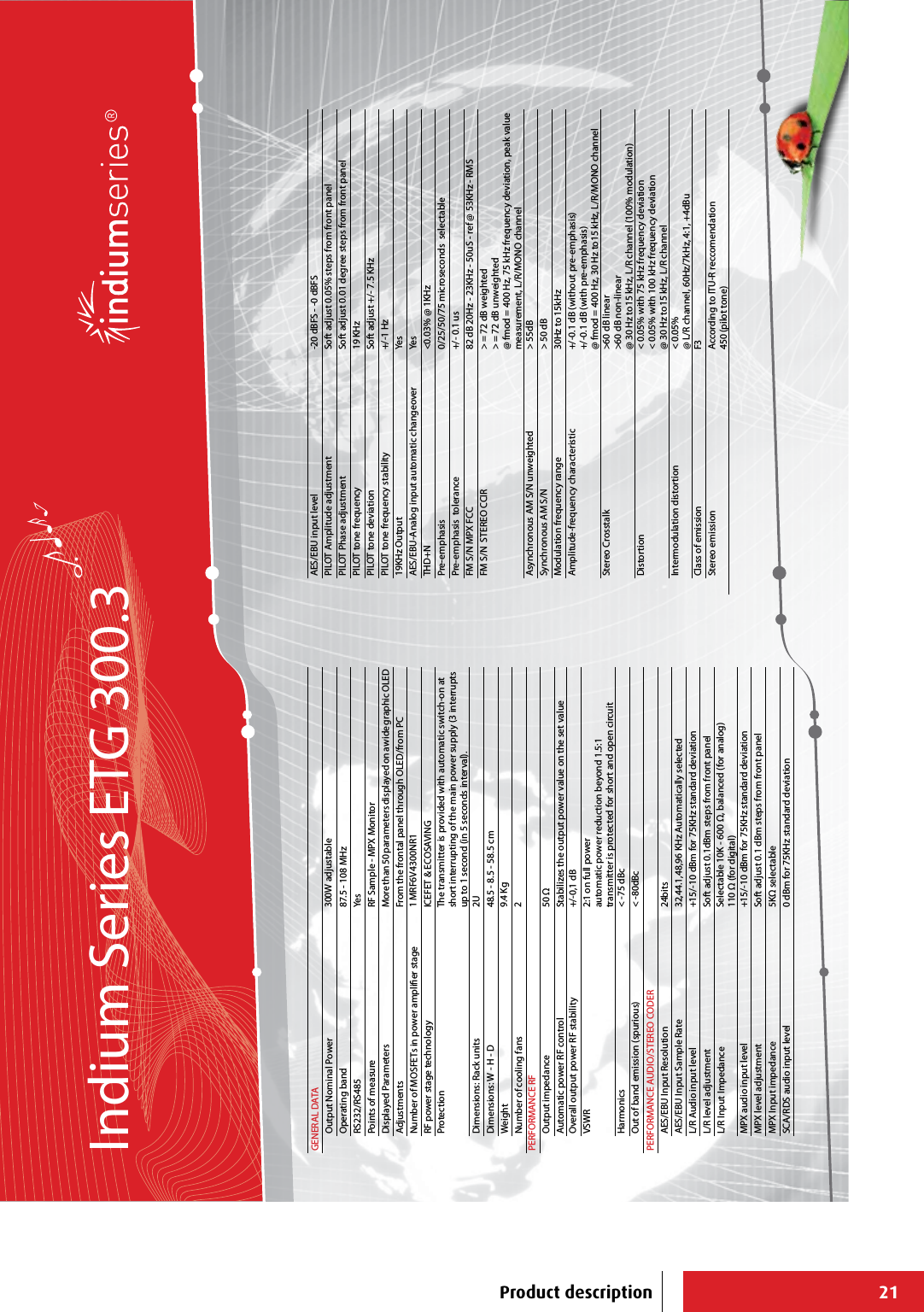
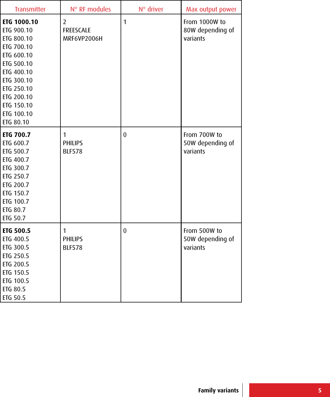
![12[4][8][7][5] [1][6][2][3][9][10][11] [12] [13][14]Product description](https://usermanual.wiki/305-BROADCAST/ETG150IS.User-Manual-1/User-Guide-2906740-Page-14.png)
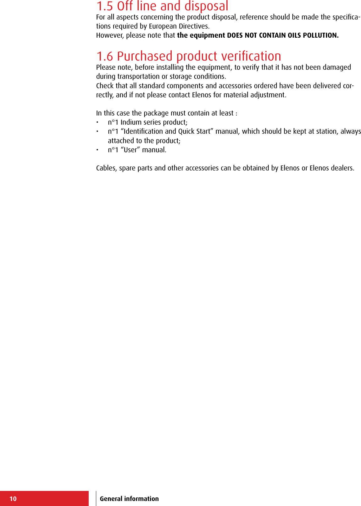
![13ConnectorPin No. Signal RemarkCN3 Panel board 1 TX_1 485 filtered outputDifferential signal (+)2 /TX_1 485 filtered outputDifferential signal (-)3 RX_1 485 filtered inputDifferential signal (+)4 / RX_1 485 filtered inputDifferential signal (-)5 GND / Common6 GND / Common7 GND / Common8 GND / Common9 GND / Common594837261ConnectorPin No. Signal RemarkJ1 or J01 Stereo or AES/EBU board1 GND / Common2 Differential audio input “po-sitive” Right channel3 Differential audio input “nega-tive” Right channel4 Frame to groundConnectorPin No. Signal RemarkJ2 or J02 Stereo or AES/EBU board1 GND / Common2 Differential audio input “po-sitive” Left channel3 Differential audio input “nega-tive” Left channel4 Frame to ground123ConnectorPin No. Signal RemarkJ3 AES/EBU board 1 GND / Common2 Differential audio input “po-sitive” Left channel3 Differential audio input “nega-tive” Left channel4 Frame to ground1232.1 External connectors description2.1.1 EIA485/Telemetry connectorN°[6] Front panel (DB9 Female)Product description2.1.2 LEFT/RIGHT connectorsN°[5] Rear panel (XLR Female)2.1.3 AES/EBU connectorN°[6] Rear panel (XLR Female)](https://usermanual.wiki/305-BROADCAST/ETG150IS.User-Manual-1/User-Guide-2906740-Page-15.png)
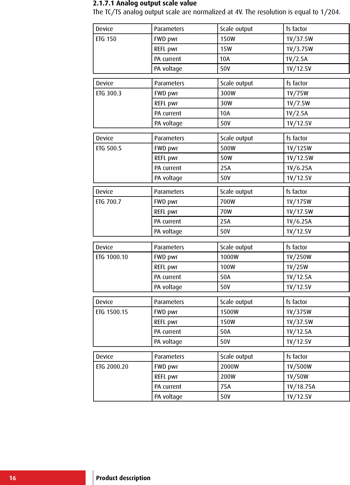
![14ConnectorPin No. Signal RemarkJ2 or CN2 Coder Stereo or MPX board1 RDS/SCA/AUX1 Input (RDS/SCA only with Coder Stereo board)2 GND / CommonConnectorPin No. Signal RemarkJ3 Coder Stereo board 1 AUX2 Input2 GND / Common12ConnectorPin No. Signal RemarkJ1 or CN1 Coder Stero or MPX board1 External MPX Input2 GND / Common12ConnectorPin No. Signal RemarkJ4 or CN3 Coder Stero or MPX board 1 Monitor MPX-19KHz Input (10KHz only with Coder Stereo board)2 GND / Common12Product description2.1.4 AUX connectorsN°[7] Rear panel (BNC Female)2.1.5 MPX connectorN°[8] Rear panel (BNC Female)2.1.6 Monitor/19kHz connectorN°[9] Rear panel (BNC Female)](https://usermanual.wiki/305-BROADCAST/ETG150IS.User-Manual-1/User-Guide-2906740-Page-16.png)
![15Connector Pin No. Signal RemarkCN1 TC/TS board1 F_TC_INTRLCK Interlock (Enable)Pin connected to ground = command active 500ms2 F_TC_TX_ON TX ONPin connected to ground = command active 500ms3 F_TC_TX_OFF TX OFFPin connected to ground = command activeV4 F_DTM_REFL_PWR Analog voltage output reflected power (see 2.1.7.1 paragraph user manual)5 GND / Common6 F_RX- EIA4857 - Not connected8 F_TX- EIA4859 GND / CommonV10 F_DTM_I_PA Analog voltage output current Power Ampli-fier (see 2.1.7.1 paragraph user manual)opencollector11 F_TS_/FLT_MAIN FAULT status mainsPin must be externally powered.“Open” status → Fault activeopencollector12 F_TS_TX_ON TX ON statusPin must be externally powered.“Closed to ground” status → TX ONopencollector13 F_TS_WARNING WarningPin must be externally powered.“Closed to ground” status → Warning active14 F_TC_ALRM_RST Reset allarmsPin connected to ground = command active15 - Spare pin16 - Reserved ElenosV17 F_DTM_FWD_PWR Analog voltage output direct power (see 2.1.7.1 paragraph user manual)18 GND / Common19 F_RX+ EIA48520 F_TX+ EIA48521 GND / CommonV22 F_DTM_V_PA Analog voltage output voltage Power Ampli-fier (see 2.1.7.1 paragraph user manual)opencollector23 F_TS_FLT_AUDIO Allarm FAULT audioPin must be externally powered.“Closed to ground” status → Alarm activeopencollector24 F_TS_/FLT Allarm FAULTPin must be externally powered.“Open” status → Alarm activeopencollector25 F_TS_REMOTE Remote statusPin must be externally powered.“Closed to ground” status → Remote signal active13251224112310229218207196185174163152141Product description2.1.7 TC/TS connector (option)N°[10] Rear panel (DB25 Female). Signals compatible with IEC 60864-1 standard).](https://usermanual.wiki/305-BROADCAST/ETG150IS.User-Manual-1/User-Guide-2906740-Page-17.png)
![17ConnectorPin No. Signal RemarkCN1 Channel board 1 Telecontrol input channel 1 (0V..12V) 0V..24V2 Telecontrol input channel 3 (0V..12V) 0V..24V3 Telecontrol input channel 5 (0V..12V) 0V..24V4 Telecontrol input channel riserve (0V..12V) 0V..24V5 GND / Common6 GND / Common7 - Not connected8 GND / Common9 GND / Common10 GND / Common11 Telesignal output channel 5 (0V..24V) Max current 50mA12 Telesignal output channel 3 (0V..24V) Max current 50mA13 Telesignal output channel 1 (0V..24V) Max current 50mA14 Telecontrol input channel 2 (0V..12V) 0V..24V15 Telecontrol input channel 4 (0V..12V) 0V..24V16 Telecontrol input channel 6 (0V..12V) 0V..24V17 - Not connected18 GND / Common19 GND / Common20 GND / Common21 GND / Common22 GND / Common23 Telesignal output channel 6 (0V..24V) Max current 50mA24 Telesignal output channel 4 (0V..24V) Max current 50mA25 Telesignal output channel 2 (0V..24V) Max current 50mA13251224112310229218207196185174163152141Product description2.1.8 Profiles connector (option)N°[11] Rear panel (DB25 Female)](https://usermanual.wiki/305-BROADCAST/ETG150IS.User-Manual-1/User-Guide-2906740-Page-19.png)
![18ConnectorPin No. Signal RemarkCN2 Channel board 1 GND / Common Standard EIA485 (0..5V)2 Signal TX- Standard EIA485 (0..5V)3 Signal TX+ Standard EIA485 (0..5V)4 Signal RX+ Standard EIA485 (0..5V)5 Signal RX-6 GND / Common7 Interlock Open Collector signal without protection diode8 GND / CommonConnectorPin No. Signal RemarkCN3 Channel board 1 ETHERNET connector2 ETHERNET connector3 ETHERNET connector4 ETHERNET connector5 ETHERNET connector6 ETHERNET connector7 ETHERNET connector8 ETHERNET connector 2 6 3 1 5 4 7 8SH1SH2ConnectorPin No. Signal RemarkCN2 TC/TS board 1 TX_1 EIA4852 /TX_1 EIA4853 RX_1 EIA4854 /RX_1 EIA4855 GND / Common6 GND / Common7 GND / Common8 GND / Common9 GND / Common594837261Product description2.1.9 TCP/IP - Reserved connectors (option)N°[12] Rear panel (RJ48)2.1.10 EIA485 connector (option)N°[13] Rear panel (DB9 Female)](https://usermanual.wiki/305-BROADCAST/ETG150IS.User-Manual-1/User-Guide-2906740-Page-20.png)