305 BROADCAST ETG150IS FM Broadcast Transmitter User Manual 1
305 BROADCAST, LLC FM Broadcast Transmitter 1
Contents
- 1. User Manual 1
- 2. User Manual 2
User Manual 1

USER MANUAL
ETG 2000.20
ETG 1500.15
ETG 1000.10
ETG 700.7
ETG 500.5
ETG 300.3
ETG 150
(the list of variants is in the manual)
SOLID STATE FM TRANSMITTER
Rev. 00- 11/07/2011
Cod. MAN1009UUK

0470
Operative Office : via G. Amendola 9, 44028 Poggio Renatico (Fe) ITALY
C.C.I.A.A. 101 216
C.Fisc. e P.IVA IT00415540384
For information and assistance please contact the Elenos Technical Assistance Service :
Phone : +39 0532 829965
Fax : +39 0532 829177
E-mail : info@elenos.com
Website : www.elenos.com (in On line Support page)
Please, give us information about the device serial number (shown on the identifying label).
Elenos s.r.l. declares that the equipment in this documentation complies with 1999/05/CE Directive.
For details see “CE Conformity” Section.
All copyrights are reserved, you may not reproduce any part of this manual, in any form, without the express written
permission of Elenos S.r.l.
UNI EN ISO 9001:2008 certified company
Certificate No.102222A

3
Revision
N° Date Description
00 11/07/2011 First release
Revision

4
Family variants
Family variants
Transmitter N° RF modules N° driver Max output power
ETG 2000.20
ETG 1900.20
ETG 1800.20
ETG 1700.20
ETG 1600.20
ETG 1500.20
ETG 1400.20
ETG 1200.20
ETG 1000.20
ETG 900.20
ETG 800.20
ETG 700.20
ETG 600.20
ETG 500.20
ETG 400.20
ETG 300.20
ETG 250.20
ETG 200.20
ETG 150.20
ETG 100.20
3
FREESCALE
MRF6VP11KH
1 From 2000W to
100W depending of
variants
ETG 1500.15
ETG 1400.15
ETG 1200.15
ETG 1000.15
ETG 900.15
ETG 800.15
ETG 700.15
ETG 600.15
ETG 500.15
ETG 400.15
ETG 300.15
ETG 250.15
ETG 200.15
ETG 150.15
ETG 100.15
ETG 80.15
2
FREESCALE
MRF6VP11KH
1 From 1500W to
80W depending of
variants

5Family variants
Transmitter N° RF modules N° driver Max output power
ETG 1000.10
ETG 900.10
ETG 800.10
ETG 700.10
ETG 600.10
ETG 500.10
ETG 400.10
ETG 300.10
ETG 250.10
ETG 200.10
ETG 150.10
ETG 100.10
ETG 80.10
2
FREESCALE
MRF6VP2006H
1 From 1000W to
80W depending of
variants
ETG 700.7
ETG 600.7
ETG 500.7
ETG 400.7
ETG 300.7
ETG 250.7
ETG 200.7
ETG 150.7
ETG 100.7
ETG 80.7
ETG 50.7
1
PHILIPS
BLF578
0 From 700W to
50W depending of
variants
ETG 500.5
ETG 400.5
ETG 300.5
ETG 250.5
ETG 200.5
ETG 150.5
ETG 100.5
ETG 80.5
ETG 50.5
1
PHILIPS
BLF578
0 From 500W to
50W depending of
variants

6
Transmitter N° RF modules N° driver Max output power
ETG 300.3
ETG 250.3
ETG 200.3
ETG 150.3
ETG 100.3
ETG 80.3
ETG 50.3
1
FREESCALE
MRF6V4300NR1
0 From 300W to
50W depending of
variants
ETG 150
ETG 100
ETG 80
ETG 50
ETG 40
ETG 30
ETG 20
ETG 10
1
FREESCALE
MRF6V2150NR1
0 From 150W to
10W depending of
variants
Family variants

7
1 General information .................................................................................................................. 9
1.1 Intended use ...................................................................................................................... 9
1.2 Shipment ............................................................................................................................ 9
1.3 Unpacking .......................................................................................................................... 9
1.4 Storage ............................................................................................................................... 9
1.5 Off line and disposal ........................................................................................................ 10
1.6 Purchased product verification ........................................................................................ 10
2 Product description ................................................................................................................. 11
2.1 External connectors description....................................................................................... 13
2.1.1 EIA485/Telemetry connector ................................................................................... 13
2.1.2 LEFT/RIGHT connectors ............................................................................................. 13
2.1.3 AES/EBU connector ................................................................................................... 13
2.1.4 AUX connectors ......................................................................................................... 14
2.1.5 MPX connector .......................................................................................................... 14
2.1.6 Monitor/19kHz connector ........................................................................................ 14
2.1.7 TC/TS connector (option) ......................................................................................... 15
2.1.7.1 Analog output scale value ................................................................................ 16
2.1.8 Profiles connector (option) ...................................................................................... 17
2.1.9 TCP/IP - Reserved connectors (option) .................................................................... 18
2.1.10 EIA485 connector (option) ..................................................................................... 18
2.2 Technical brochure ........................................................................................................... 19
2.3 Protections ....................................................................................................................... 33
2.3.1 Software protections ................................................................................................ 33
2.3.1.1 IPF (Intelligent Proportional Foldback) ............................................................. 33
2.3.1.2 IPC (Intelligent Power Control) ......................................................................... 33
2.3.1.3 Safety Management (option Lifextender ®) ................................................... 33
2.3.2 Hardware protections ............................................................................................... 34
2.4 Options ............................................................................................................................. 35
3 Use instructions ....................................................................................................................... 37
3.1 User interface ................................................................................................................... 37
3.1.1 Status & Settings ...................................................................................................... 40
3.1.2 Audio Setting ............................................................................................................ 41
3.1.3 Audio Levels ............................................................................................................. 41
3.1.4 View & Setting .......................................................................................................... 41
3.1.5 Temperatures ............................................................................................................ 42
3.1.6 Alarms List ................................................................................................................ 42
3.1.7 Events History ........................................................................................................... 42
3.1.8 RF Data ..................................................................................................................... 43
3.1.9 PSUs Data .................................................................................................................. 43
3.1.10 Password ................................................................................................................ 43
3.1.11 Lifextender ............................................................................................................. 44
3.1.12 Inputs Level ............................................................................................................ 44
3.1.13 Aux Inputs Level ..................................................................................................... 44
3.1.14 Pilot Level & Phase ................................................................................................. 45
3.1.15 Exciter Clipping ....................................................................................................... 45
Index
Index

8
3.1.16 Alarms Audio Settings ............................................................................................ 45
3.1.17 AES/EBU Settings .................................................................................................... 46
3.1.18 Time Base ............................................................................................................... 46
3.1.19 Profile Summary ..................................................................................................... 46
3.1.20 Pre Amplifier .......................................................................................................... 47
3.1.21 Voltages .................................................................................................................. 47
3.1.22 System Info ............................................................................................................. 47
3.1.23 System Time ........................................................................................................... 48
3.1.24 Clock Pwr Target ..................................................................................................... 48
3.1.25 Max Reflected Power ............................................................................................. 49
3.1.26 Comm.ID LC/RT Disp.Mode ..................................................................................... 49
3.1.27 Password Setting .................................................................................................... 49
3.1.28 Password Recovery ................................................................................................. 50
3.1.29 Foldback Setting ..................................................................................................... 50
3.1.30 Com1 Speed Set...................................................................................................... 50
3.1.31 Enable Alarms SMS ................................................................................................. 51
3.1.32 Enable Alarms Bit ................................................................................................... 51
3.1.33 User Alarms Data .................................................................................................... 51
3.1.34 User Alarms Timers ................................................................................................ 52
3.1.35 UPS Settings............................................................................................................ 52
3.1.36 Uart Info .................................................................................................................. 53
3.1.37 SMS Enable/-3dB Alarm ......................................................................................... 53
3.1.38 GSM Field ................................................................................................................ 54
3.1.39 Phone N° ................................................................................................................ 54
3.1.40 SMS Diagnostic ....................................................................................................... 54
3.2 Alarms/events list ........................................................................................................... 55
3.3 SMS list ............................................................................................................................. 57
3.3.1 SMS command (send) .............................................................................................. 57
3.3.2 SMS status/alarm (reception) .................................................................................. 57
3.4 Optional equipment can be connected ........................................................................... 59
3.4.1 PC connection ........................................................................................................... 59
3.4.1.1 Hyperterminal screen ....................................................................................... 60
3.4.2 Telemetry connection ............................................................................................... 67
3.4.3 Exchange unit and/or audio matrix connection ...................................................... 68
3.4.4 Amplifier connection ................................................................................................ 70
3.4.5 E.BOX module connection ........................................................................................ 71
4 Maintenance ........................................................................................................................... 73
4.1 Maintenance (cleaning, replacement, control) ............................................................... 73
4.2 Malfunction (effects, causes and solutions) ................................................................... 74
Index

9
1 General information
General information
1.1 Intended use
The products described in this document are solid state transmitters with an output
power adjustable from 0W up to the maximum rating (see “Family variants“ section),
using in FM band between 87.5 and 108MHz at 10kHz steps.
The Indium series, this is its name, that already stands for new lines, new colors, an
innovative look, and especially new technology designed to outstanding performance,
has been further improved.
More compact size, weight not exceeding 10kg, with an extension of output power
maximum range (up to 2000W).
The RF performance, obtained with a number of modules from 3 to 1 depending on the
model purchased, are close to the finish line that is not superable in terms of efficiency,
with devices and technologies of today.
Thanks to these features, ETG series allows a drastic electricity costs reduction.
The product distinguishing features remain : ECOSAVING, ICEFET, VSWR PEAK HOLD, moni-
toring capability, protection against corrosion.
The options would satisfy all needs : MPX, STEREO or AES/EBU versions; TC/TS, TC/
TS+ETHERNET+PROFILES options; LIFEXTENDER.
1.2 Shipment
The shipment may only be performed in its original packaging.
However, although this is designed to avoid product damages, even in mishandling
case, it is recommended to respect the “UP/DOWN” side and to not give shocks.
To make sure that the type of transport and lifting equipment type are capable to sup-
port the weight.
1.3 Unpacking
The staff, handling the product, should operate with gloves and shoes against injury.
Before lifting or handling equipment to verify that you have done to clear the area
of operation, considering a safety area large enough to avoid damage to persons or
objects that may be in the range of maneuver.
1.4 Storage
If you wish, for whatever reason, store the product it is necessary that:
• the temperatures, in the storage, are not exceeded -20 ° - +55 ° C, with humidity
not exceeding 90% at 55 ° C;
• the equipment must be disconnected from the sources of energy;
• the equipment is clean and there are any dust;
• the equipment is covered with a waterproof sheet.

10 General information
1.5 Off line and disposal
For all aspects concerning the product disposal, reference should be made the specifica-
tions required by European Directives.
However, please note that the equipment DOES NOT CONTAIN OILS POLLUTION.
1.6 Purchased product verification
Please note, before installing the equipment, to verify that it has not been damaged
during transportation or storage conditions.
Check that all standard components and accessories ordered have been delivered cor-
rectly, and if not please contact Elenos for material adjustment.
In this case the package must contain at least :
• n°1 Indium series product;
• n°1 “Identification and Quick Start” manual, which should be kept at station, always
attached to the product;
• n°1 “User” manual.
Cables, spare parts and other accessories can be obtained by Elenos or Elenos dealers.
11
[4][8]
[7] [5]
[1]
[6]
[2]
[3]
[9]
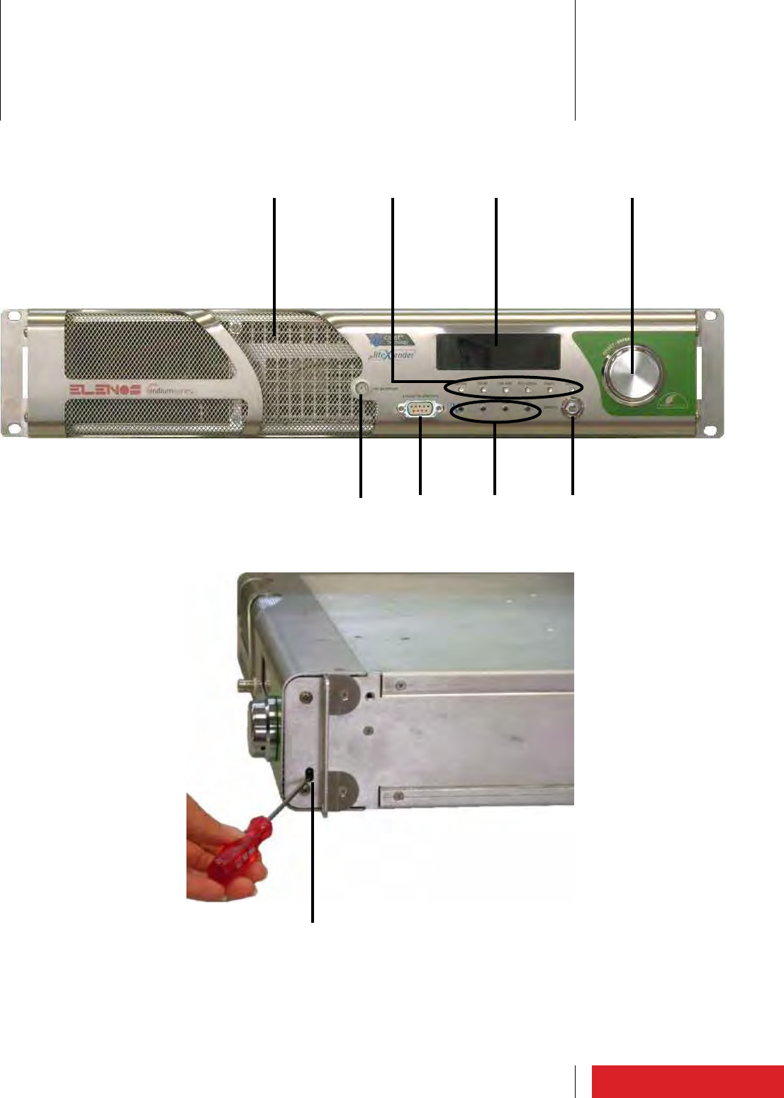
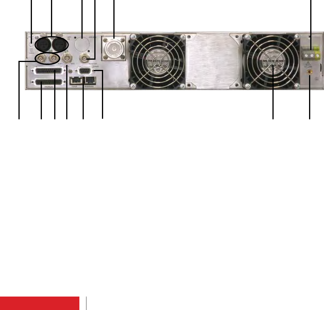
2 Product description
Product description
12
[4]
[8][7]
[5] [1][6]
[2][3]
[9]
[10][11] [12] [13]
[14]
Product description
13
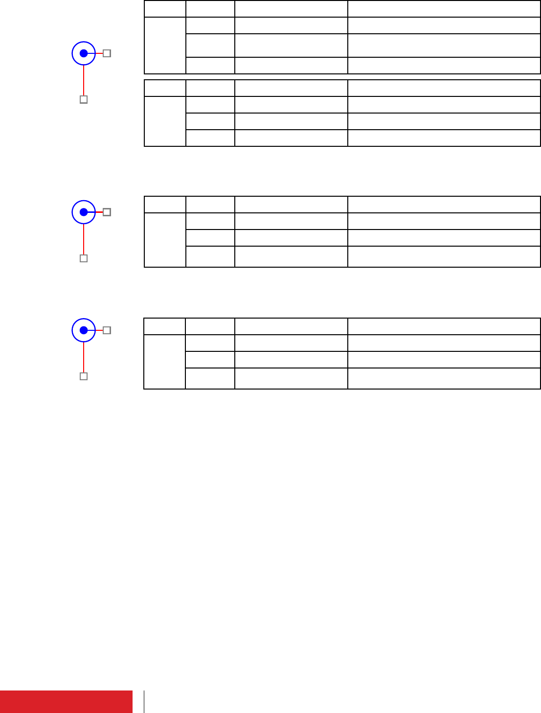
ConnectorPin No. Signal Remark
CN3
Panel
board 1 TX_1 485 filtered output
Differential signal (+)
2 /TX_1 485 filtered output
Differential signal (-)
3 RX_1 485 filtered input
Differential signal (+)
4 / RX_1 485 filtered input
Differential signal (-)
5 GND / Common
6 GND / Common
7 GND / Common
8 GND / Common
9 GND / Common
5
9
4
8
3
7
2
6
1
ConnectorPin No. Signal Remark
J1 or
J01
Stereo
or
AES/
EBU
board
1 GND / Common
2 Differential audio input “po-
sitive” Right channel
3 Differential audio input “nega-
tive” Right channel
4 Frame to ground
ConnectorPin No. Signal Remark
J2 or
J02
Stereo
or
AES/
EBU
board
1 GND / Common
2 Differential audio input “po-
sitive” Left channel
3 Differential audio input “nega-
tive” Left channel
4 Frame to ground
12
3
ConnectorPin No. Signal Remark
J3
AES/
EBU
board 1 GND / Common
2 Differential audio input “po-
sitive” Left channel
3 Differential audio input “nega-
tive” Left channel
4 Frame to ground
12
3
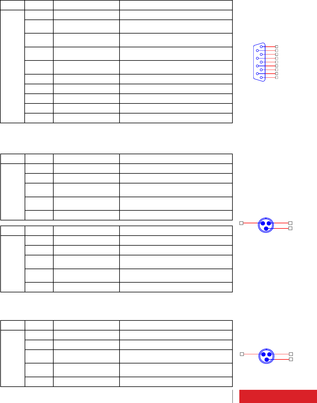
2.1 External connectors description
2.1.1 EIA485/Telemetry connector
N°[6] Front panel (DB9 Female)
Product description
2.1.2 LEFT/RIGHT connectors
N°[5] Rear panel (XLR Female)
2.1.3 AES/EBU connector
N°[6] Rear panel (XLR Female)
14
ConnectorPin No. Signal Remark
J2 or
CN2
Coder
Stereo
or MPX
board
1 RDS/SCA/AUX1 Input (RDS/SCA only with Coder Stereo
board)
2 GND / Common
ConnectorPin No. Signal Remark
J3 Coder
Stereo
board 1 AUX2 Input
2 GND / Common
1
2
ConnectorPin No. Signal Remark
J1 or
CN1
Coder
Stero
or MPX
board
1 External MPX Input
2 GND / Common
1
2
ConnectorPin No. Signal Remark
J4 or
CN3
Coder
Stero
or MPX
board
1 Monitor MPX-19KHz Input (10KHz only with Coder Stereo board)
2 GND / Common
1
2
Product description
2.1.4 AUX connectors
N°[7] Rear panel (BNC Female)
2.1.5 MPX connector
N°[8] Rear panel (BNC Female)
2.1.6 Monitor/19kHz connector
N°[9] Rear panel (BNC Female)
15
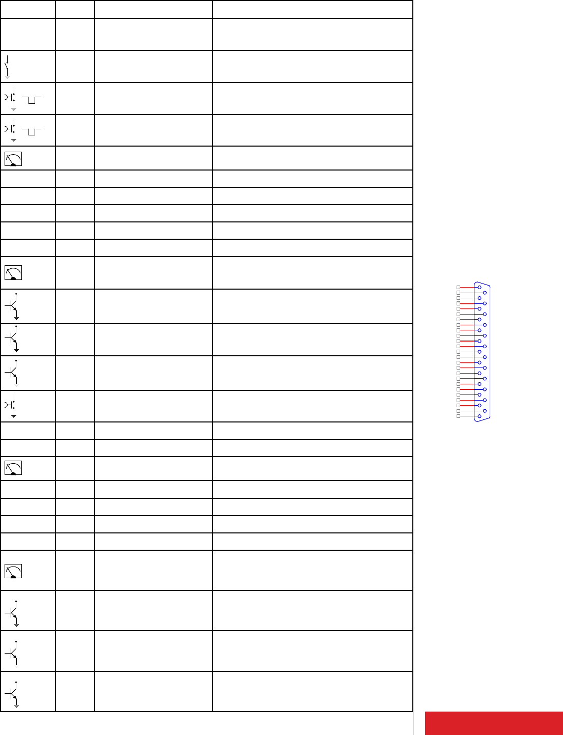
Connector Pin No. Signal Remark
CN1
TC/TS
board
1 F_TC_INTRLCK Interlock (Enable)
Pin connected to ground = command active
500ms
2 F_TC_TX_ON TX ON
Pin connected to ground = command active
500ms
3 F_TC_TX_OFF TX OFF
Pin connected to ground = command active
V4 F_DTM_REFL_PWR Analog voltage output reflected power (see 2
.1.7.1 paragraph user manual)
5 GND / Common
6 F_RX- EIA485
7 - Not connected
8 F_TX- EIA485
9 GND / Common
V10 F_DTM_I_PA Analog voltage output current Power Ampli-
fier (see 2.1.7.1 paragraph user manual)
open
collector
11 F_TS_/FLT_MAIN FAULT status mains
Pin must be externally powered.
“Open” status → Fault active
open
collector
12 F_TS_TX_ON TX ON status
Pin must be externally powered.
“Closed to ground” status → TX ON
open
collector
13 F_TS_WARNING Warning
Pin must be externally powered.
“Closed to ground” status → Warning active
14 F_TC_ALRM_RST Reset allarms
Pin connected to ground = command active
15 - Spare pin
16 - Reserved Elenos
V17 F_DTM_FWD_PWR Analog voltage output direct power (see 2
.1.7.1 paragraph user manual)
18 GND / Common
19 F_RX+ EIA485
20 F_TX+ EIA485
21 GND / Common
V
22 F_DTM_V_PA Analog voltage output voltage Power Ampli-
fier (see 2.1.7.1 paragraph user manual)
open
collector
23 F_TS_FLT_AUDIO Allarm FAULT audio
Pin must be externally powered.
“Closed to ground” status → Alarm active
open
collector
24 F_TS_/FLT Allarm FAULT
Pin must be externally powered.
“Open” status → Alarm active
open
collector
25 F_TS_REMOTE Remote status
Pin must be externally powered.
“Closed to ground” status → Remote signal
active
13
25
12
24
11
23
10
22
9
21
8
20
7
19
6
18
5
17
4
16
3
15
2
14
1
Product description
2.1.7 TC/TS connector (option)
N°[10] Rear panel (DB25 Female). Signals compatible with IEC 60864-1 standard).

16
Device Parameters Scale output fs factor
ETG 150 FWD pwr 150W 1V/37.5W
REFL pwr 15W 1V/3.75W
PA current 10A 1V/2.5A
PA voltage 50V 1V/12.5V
Device Parameters Scale output fs factor
ETG 300.3 FWD pwr 300W 1V/75W
REFL pwr 30W 1V/7.5W
PA current 10A 1V/2.5A
PA voltage 50V 1V/12.5V
Device Parameters Scale output fs factor
ETG 500.5 FWD pwr 500W 1V/125W
REFL pwr 50W 1V/12.5W
PA current 25A 1V/6.25A
PA voltage 50V 1V/12.5V
Device Parameters Scale output fs factor
ETG 700.7 FWD pwr 700W 1V/175W
REFL pwr 70W 1V/17.5W
PA current 25A 1V/6.25A
PA voltage 50V 1V/12.5V
Device Parameters Scale output fs factor
ETG 1500.15 FWD pwr 1500W 1V/375W
REFL pwr 150W 1V/37.5W
PA current 50A 1V/12.5A
PA voltage 50V 1V/12.5V
Device Parameters Scale output fs factor
ETG 2000.20 FWD pwr 2000W 1V/500W
REFL pwr 200W 1V/50W
PA current 75A 1V/18.75A
PA voltage 50V 1V/12.5V
Device Parameters Scale output fs factor
ETG 1000.10 FWD pwr 1000W 1V/250W
REFL pwr 100W 1V/25W
PA current 50A 1V/12.5A
PA voltage 50V 1V/12.5V
Product description
2.1.7.1 Analog output scale value
The TC/TS analog output scale are normalized at 4V. The resolution is equal to 1/204.

17
ConnectorPin No. Signal Remark
CN1
Channel
board 1 Telecontrol input channel
1 (0V..12V) 0V..24V
2 Telecontrol input channel
3 (0V..12V) 0V..24V
3 Telecontrol input channel
5 (0V..12V) 0V..24V
4 Telecontrol input channel
riserve (0V..12V) 0V..24V
5 GND / Common
6 GND / Common
7 - Not connected
8 GND / Common
9 GND / Common
10 GND / Common
11 Telesignal output channel
5 (0V..24V) Max current 50mA
12 Telesignal output channel
3 (0V..24V) Max current 50mA
13 Telesignal output channel
1 (0V..24V) Max current 50mA
14 Telecontrol input channel
2 (0V..12V) 0V..24V
15 Telecontrol input channel
4 (0V..12V) 0V..24V
16 Telecontrol input channel
6 (0V..12V) 0V..24V
17 - Not connected
18 GND / Common
19 GND / Common
20 GND / Common
21 GND / Common
22 GND / Common
23 Telesignal output channel
6 (0V..24V) Max current 50mA
24 Telesignal output channel
4 (0V..24V) Max current 50mA
25 Telesignal output channel
2 (0V..24V) Max current 50mA
13
25
12
24
11
23
10
22
9
21
8
20
7
19
6
18
5
17
4
16
3
15
2
14
1
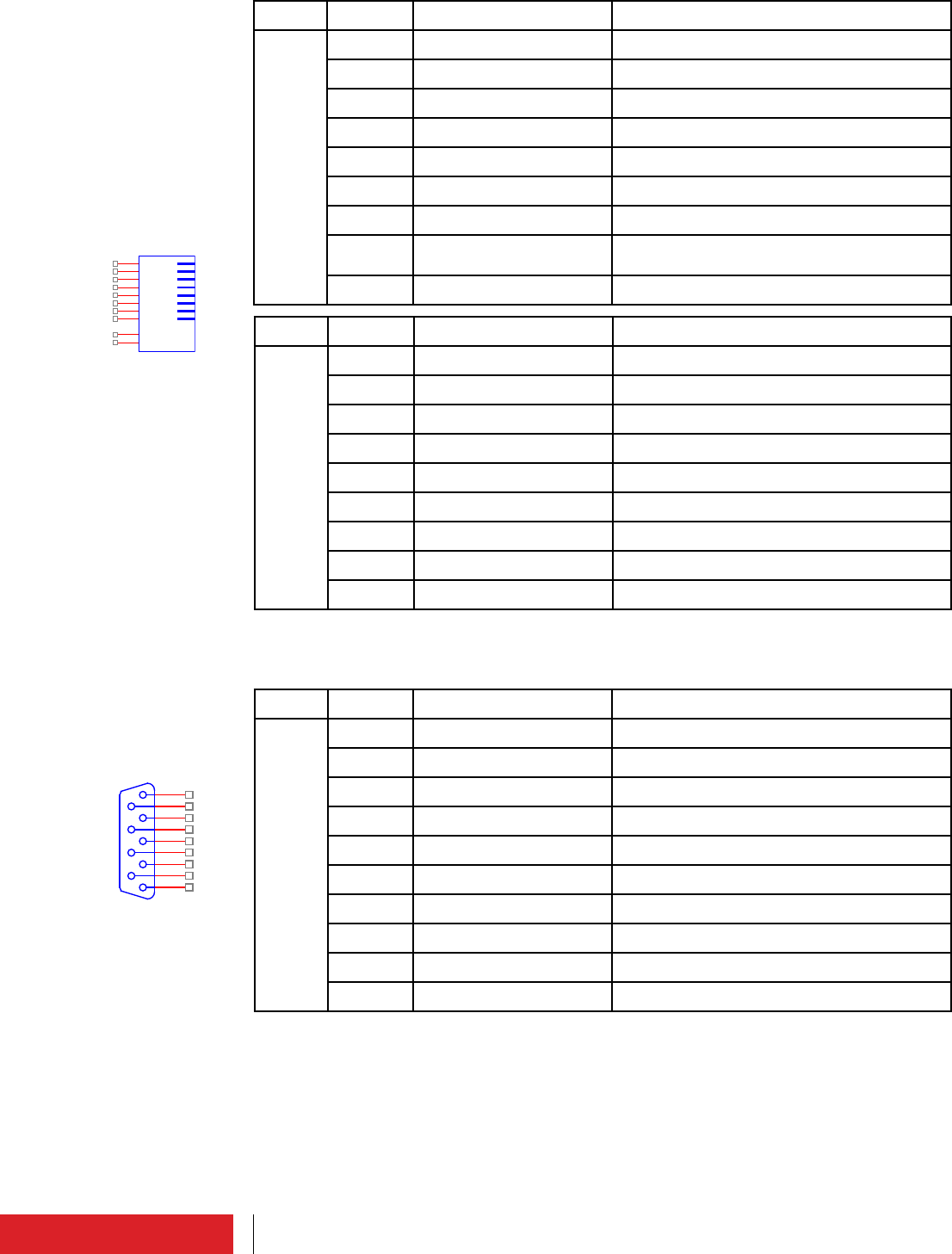
Product description
2.1.8 Profiles connector (option)
N°[11] Rear panel (DB25 Female)
18
ConnectorPin No. Signal Remark
CN2
Channel
board 1 GND / Common Standard EIA485 (0..5V)
2 Signal TX- Standard EIA485 (0..5V)
3 Signal TX+ Standard EIA485 (0..5V)
4 Signal RX+ Standard EIA485 (0..5V)
5 Signal RX-
6 GND / Common
7 Interlock Open Collector signal without protection
diode
8 GND / Common
ConnectorPin No. Signal Remark
CN3
Channel
board 1 ETHERNET connector
2 ETHERNET connector
3 ETHERNET connector
4 ETHERNET connector
5 ETHERNET connector
6 ETHERNET connector
7 ETHERNET connector
8 ETHERNET connector
2
6
3
1
5
4
7
8
SH1
SH2
ConnectorPin No. Signal Remark
CN2
TC/TS
board 1 TX_1 EIA485
2 /TX_1 EIA485
3 RX_1 EIA485
4 /RX_1 EIA485
5 GND / Common
6 GND / Common
7 GND / Common
8 GND / Common
9 GND / Common
5
9
4
8
3
7
2
6
1
Product description
2.1.9 TCP/IP - Reserved connectors (option)
N°[12] Rear panel (RJ48)
2.1.10 EIA485 connector (option)
N°[13] Rear panel (DB9 Female)

19
GENERAL DATA
Output Nominal Power 150W adjustable
Operating band 87.5 - 108 MHz
RS232/RS485 Yes
Points of measure RF Sample - MPX Monitor
Displayed Parameters More than 50 parameters displayed on a wide graphic OLED
Adjustments From the frontal panel through OLED/from PC
Number of MOSFETs in power amplier stage 1 MRF6V2150NR1
RF power stage technology ICEFET & ECOSAVING
Protection The transmitter is provided with automatic switch-on at
short interrupting of the main power supply (3 interrupts
up to 1 second (in 5 seconds interval).
Dimensions: Rack units 2U
Dimensions: W - H - D 48.5 - 8.5 - 58.5 cm
Weight 9.4 Kg
Number of cooling fans 2
PERFORMANCE RF
Output impedance 50 Ω
Automatic power RF control Stabilizes the output power value on the set value
Overall output power RF stability +/-0,1 dB
VSWR 2:1 on full power
automatic power reduction beyond 1.5:1
transmitter is protected for short and open circuit
Harmonics < -75 dBc
Out of band emission (spurious) < -80dBc
PERFORMANCE AUDIO/STEREO CODER
AES/EBU Input Resolution 24bits
AES/EBU Input Sample Rate 32,44.1,48,96 KHz Automatically selected
L/R Audio input level +15/-10 dBm for 75KHz standard deviation
L/R level adjustment Soft adjust 0.1dBm steps from front panel
L/R Input Impedance Selectable 10K - 600 Ω, balanced (for analog)
110 Ω (for digital)
MPX audio input level +15/-10 dBm for 75KHz standard deviation
MPX level adjustment Soft adjust 0.1 dBm steps from front panel
MPX Input impedance 5KΩ selectable
SCA/RDS audio input level 0 dBm for 75KHz standard deviation
AES/EBU input level -20 dBFS - -0 dBFS
PILOT Amplitude adjustment Soft adjust 0.05% steps from front panel
PILOT Phase adjustment Soft adjust 0.01 degree steps from front panel
PILOT tone frequency 19 KHz
PILOT tone deviation Soft adjust +/- 7.5 KHz
PILOT tone frequency stability +/-1 Hz
19KHz Output Yes
AES/EBU-Analog input automatic changeover Yes
THD+N <0.03% @ 1KHz
Pre-emphasis 0/25/50/75 microseconds selectable
Pre-emphasis tolerance +/- 0.1 us
FM S/N MPX FCC 82 dB 20Hz - 23KHz - 50uS - ref @ 53KHz - RMS
FM S/N STEREO CCIR > = 72 dB weighted
> = 72 dB unweighted
@ fmod = 400 Hz, 75 kHz frequency deviation, peak value
measurement, L/R/MONO channel
Asynchronous AM S/N unweighted > 55dB
Synchronous AM S/N > 50 dB
Modulation frequency range 30Hz to 15kHz
Amplitude-frequency characteristic +/-0.1 dB (without pre-emphasis)
+/-0.1 dB (with pre-emphasis)
@ fmod = 400 Hz, 30 Hz to15 kHz, L/R/MONO channel
Stereo Crosstalk >60 dB linear
>60 dB non-linear
@ 30 Hz to15 kHz, L/R channel (100% modulation)
Distortion < 0.05% with 75 kHz frequency deviation
< 0.05% with 100 kHz frequency deviation
@ 30 Hz to15 kHz, L/R channel
Intermodulation distortion < 0.05%
@ L/R channel, 60Hz/7kHz, 4:1, +4dBu
Class of emission F3
Stereo emission According to ITU-R reccomendation
450 (pilot tone)
Indium Series ETG 150
Product description
2.2 Technical brochure

20
Indium Series ETG 150
PERFORMANCE EXCITER
PLL lock time <10sec
Intermodulation distortion <0.05% Measured with two of tones 1KHz & 1.3KHz, ratio
1:1 at 100% modulation
Frequency deviation +/- 75 KHz 0.1 dB steps adjustable
Maximum frequency deviation +/- 150 kHz
Frequency stability +/- 200 Hz/year
RF Frequency steps 10 KHz
Phase Response 0.1 degree from linear phase; 53kHz to 100kHz
Modulation Capability +/-250 KHz
INSTALLATION REQUIREMENTS
Power supply 110, 230 Two-Singlephase Version 50-60Hz VAC
Power consumption (typical) 230W
Current consumption (typical@230V) 1A
Overall eciency (typical from -3dB to Pnom) > = 70%
Power factor > 0.95
COOLING/NOISE/ELECTRICMAGNETIC DATA
Cooling system Forced air-cooling
Electric eld < 10V/m
@ one meter in front of the transmitter cabinets during
normal operation
Magnetic eld < 4 A/m
@ one meter in front of the transmitter cabinets during
normal operation
Acoustic noise < 65 phones
@ transmitter room, 2 m distance of the front of transmit-
ter
ENVIRONMENT
Temperature range (operating) -5 - +45 °C
Temperature range (non operating) -20 - +55 °C
Humidity range (operating) 95% @ 40 °C
Humidity range (non operating) 90% @ 55 °C
Altitude range (operating) <3000 meters
Altitude range (non operating) <15000 meters
TELECONTROL & TELEMETRY
Remote control Yes
Remote Control at clean contacts Yes
SNMP option Yes (external)
Product description

21
GENERAL DATA
Output Nominal Power 300W adjustable
Operating band 87.5 - 108 MHz
RS232/RS485 Yes
Points of measure RF Sample - MPX Monitor
Displayed Parameters More than 50 parameters displayed on a wide graphic OLED
Adjustments From the frontal panel through OLED/from PC
Number of MOSFETs in power amplier stage 1 MRF6V4300NR1
RF power stage technology ICEFET & ECOSAVING
Protection The transmitter is provided with automatic switch-on at
short interrupting of the main power supply (3 interrupts
up to 1 second (in 5 seconds interval).
Dimensions: Rack units 2U
Dimensions: W - H - D 48.5 - 8.5 - 58.5 cm
Weight 9.4 Kg
Number of cooling fans 2
PERFORMANCE RF
Output impedance 50 Ω
Automatic power RF control Stabilizes the output power value on the set value
Overall output power RF stability +/-0,1 dB
VSWR 2:1 on full power
automatic power reduction beyond 1.5:1
transmitter is protected for short and open circuit
Harmonics < -75 dBc
Out of band emission (spurious) < -80dBc
PERFORMANCE AUDIO/STEREO CODER
AES/EBU Input Resolution 24bits
AES/EBU Input Sample Rate 32,44.1,48,96 KHz Automatically selected
L/R Audio input level +15/-10 dBm for 75KHz standard deviation
L/R level adjustment Soft adjust 0.1dBm steps from front panel
L/R Input Impedance Selectable 10K - 600 Ω, balanced (for analog)
110 Ω (for digital)
MPX audio input level +15/-10 dBm for 75KHz standard deviation
MPX level adjustment Soft adjust 0.1 dBm steps from front panel
MPX Input impedance 5KΩ selectable
SCA/RDS audio input level 0 dBm for 75KHz standard deviation
AES/EBU input level -20 dBFS - -0 dBFS
PILOT Amplitude adjustment Soft adjust 0.05% steps from front panel
PILOT Phase adjustment Soft adjust 0.01 degree steps from front panel
PILOT tone frequency 19 KHz
PILOT tone deviation Soft adjust +/- 7.5 KHz
PILOT tone frequency stability +/-1 Hz
19KHz Output Yes
AES/EBU-Analog input automatic changeover Yes
THD+N <0.03% @ 1KHz
Pre-emphasis 0/25/50/75 microseconds selectable
Pre-emphasis tolerance +/- 0.1 us
FM S/N MPX FCC 82 dB 20Hz - 23KHz - 50uS - ref @ 53KHz - RMS
FM S/N STEREO CCIR > = 72 dB weighted
> = 72 dB unweighted
@ fmod = 400 Hz, 75 kHz frequency deviation, peak value
measurement, L/R/MONO channel
Asynchronous AM S/N unweighted > 55dB
Synchronous AM S/N > 50 dB
Modulation frequency range 30Hz to 15kHz
Amplitude-frequency characteristic +/-0.1 dB (without pre-emphasis)
+/-0.1 dB (with pre-emphasis)
@ fmod = 400 Hz, 30 Hz to15 kHz, L/R/MONO channel
Stereo Crosstalk >60 dB linear
>60 dB non-linear
@ 30 Hz to15 kHz, L/R channel (100% modulation)
Distortion < 0.05% with 75 kHz frequency deviation
< 0.05% with 100 kHz frequency deviation
@ 30 Hz to15 kHz, L/R channel
Intermodulation distortion < 0.05%
@ L/R channel, 60Hz/7kHz, 4:1, +4dBu
Class of emission F3
Stereo emission According to ITU-R reccomendation
450 (pilot tone)
Indium Series ETG 300.3
Product description

22
Indium Series ETG 300.3
PERFORMANCE EXCITER
PLL lock time <10sec
Intermodulation distortion <0.05% Measured with two of tones 1KHz & 1.3KHz, ratio
1:1 at 100% modulation
Frequency deviation +/- 75 KHz 0.1 dB steps adjustable
Maximum frequency deviation +/- 150 kHz
Frequency stability +/- 200 Hz/year
RF Frequency steps 10 KHz
Phase Response 0.1 degree from linear phase; 53kHz to 100kHz
Modulation Capability +/-250 KHz
INSTALLATION REQUIREMENTS
Power supply 110, 230 Two-Singlephase Version 50-60Hz VAC
Power consumption (typical) 430W
Current consumption (typical@230V) 1.9A
Overall eciency (typical from -3dB to Pnom) > = 70%
Power factor > 0.95
COOLING/NOISE/ELECTRICMAGNETIC DATA
Cooling system Forced air-cooling
Electric eld < 10V/m
@ one meter in front of the transmitter cabinets during
normal operation
Magnetic eld < 4 A/m
@ one meter in front of the transmitter cabinets during
normal operation
Acoustic noise < 65 phones
@ transmitter room, 2 m distance of the front of transmit-
ter
ENVIRONMENT
Temperature range (operating) -5 - +45 °C
Temperature range (non operating) -20 - +55 °C
Humidity range (operating) 95% @ 40 °C
Humidity range (non operating) 90% @ 55 °C
Altitude range (operating) <3000 meters
Altitude range (non operating) <15000 meters
TELECONTROL & TELEMETRY
Remote control Yes
Remote Control at clean contacts Yes
SNMP option Yes (external)
Product description

23
GENERAL DATA
Output Nominal Power 500W adjustable
Operating band 87.5 - 108 MHz
RS232/RS485 Yes
Points of measure RF Sample - MPX Monitor
Displayed Parameters More than 50 parameters displayed on a wide graphic OLED
Adjustments From the frontal panel through OLED/from PC
Number of MOSFETs in power amplier stage 1 BLF578
RF power stage technology ICEFET & ECOSAVING
Protection The transmitter is provided with automatic switch-on at
short interrupting of the main power supply (3 interrupts
up to 1 second (in 5 seconds interval).
Dimensions: Rack units 2U
Dimensions: W - H - D 48.5 - 8.5 - 58.5 cm
Weight 9.4 Kg
Number of cooling fans 2
PERFORMANCE RF
Output impedance 50 Ω
Automatic power RF control Stabilizes the output power value on the set value
Overall output power RF stability +/-0,1 dB
VSWR 2:1 on full power
automatic power reduction beyond 1.5:1
transmitter is protected for short and open circuit
Harmonics < -75 dBc
Out of band emission (spurious) < -80dBc
PERFORMANCE AUDIO/STEREO CODER
AES/EBU Input Resolution 24bits
AES/EBU Input Sample Rate 32,44.1,48,96 KHz Automatically selected
L/R Audio input level +15/-10 dBm for 75KHz standard deviation
L/R level adjustment Soft adjust 0.1dBm steps from front panel
L/R Input Impedance Selectable 10K - 600 Ω, balanced (for analog)
110 Ω (for digital)
MPX audio input level +15/-10 dBm for 75KHz standard deviation
MPX level adjustment Soft adjust 0.1 dBm steps from front panel
MPX Input impedance 5KΩ selectable
SCA/RDS audio input level 0 dBm for 75KHz standard deviation
AES/EBU input level -20 dBFS - -0 dBFS
PILOT Amplitude adjustment Soft adjust 0.05% steps from front panel
PILOT Phase adjustment Soft adjust 0.01 degree steps from front panel
PILOT tone frequency 19 KHz
PILOT tone deviation Soft adjust +/- 7.5 KHz
PILOT tone frequency stability +/-1 Hz
19KHz Output Yes
AES/EBU-Analog input automatic changeover Yes
THD+N <0.03% @ 1KHz
Pre-emphasis 0/25/50/75 microseconds selectable
Pre-emphasis tolerance +/- 0.1 us
FM S/N MPX FCC 82 dB 20Hz - 23KHz - 50uS - ref @ 53KHz - RMS
FM S/N STEREO CCIR > = 72 dB weighted
> = 72 dB unweighted
@ fmod = 400 Hz, 75 kHz frequency deviation, peak value
measurement, L/R/MONO channel
Asynchronous AM S/N unweighted > 55dB
Synchronous AM S/N > 50 dB
Modulation frequency range 30Hz to 15kHz
Amplitude-frequency characteristic +/-0.1 dB (without pre-emphasis)
+/-0.1 dB (with pre-emphasis)
@ fmod = 400 Hz, 30 Hz to15 kHz, L/R/MONO channel
Stereo Crosstalk >60 dB linear
>60 dB non-linear
@ 30 Hz to15 kHz, L/R channel (100% modulation)
Distortion < 0.05% with 75 kHz frequency deviation
< 0.05% with 100 kHz frequency deviation
@ 30 Hz to15 kHz, L/R channel
Intermodulation distortion < 0.05%
@ L/R channel, 60Hz/7kHz, 4:1, +4dBu
Class of emission F3
Stereo emission According to ITU-R reccomendation
450 (pilot tone)
Indium Series ETG 500.5
Product description

24
Indium Series ETG 500.5
PERFORMANCE EXCITER
PLL lock time <10sec
Intermodulation distortion <0.05% Measured with two of tones 1KHz & 1.3KHz, ratio
1:1 at 100% modulation
Frequency deviation +/- 75 KHz 0.1 dB steps adjustable
Maximum frequency deviation +/- 150 kHz
Frequency stability +/- 200 Hz/year
RF Frequency steps 10 KHz
Phase Response 0.1 degree from linear phase; 53kHz to 100kHz
Modulation Capability +/-250 KHz
INSTALLATION REQUIREMENTS
Power supply 110, 230 Two-Singlephase Version 50-60Hz VAC
Power consumption (typical) 570W
Current consumption (typical@230V) 2.5A
Overall eciency (typical from -3dB to Pnom) > = 70%
Power factor > 0.95
COOLING/NOISE/ELECTRICMAGNETIC DATA
Cooling system Forced air-cooling
Electric eld < 10V/m
@ one meter in front of the transmitter cabinets during
normal operation
Magnetic eld < 4 A/m
@ one meter in front of the transmitter cabinets during
normal operation
Acoustic noise < 65 phones
@ transmitter room, 2 m distance of the front of transmit-
ter
ENVIRONMENT
Temperature range (operating) -5 - +45 °C
Temperature range (non operating) -20 - +55 °C
Humidity range (operating) 95% @ 40 °C
Humidity range (non operating) 90% @ 55 °C
Altitude range (operating) <3000 meters
Altitude range (non operating) <15000 meters
TELECONTROL & TELEMETRY
Remote control Yes
Remote Control at clean contacts Yes
SNMP option Yes (external)
Product description

25
GENERAL DATA
Output Nominal Power 700W adjustable
Operating band 87.5 - 108 MHz
RS232/RS485 Yes
Points of measure RF Sample - MPX Monitor
Displayed Parameters More than 50 parameters displayed on a wide graphic OLED
Adjustments From the frontal panel through OLED/from PC
Number of MOSFETs in power amplier stage 1 BLF578
RF power stage technology ICEFET & ECOSAVING
Protection The transmitter is provided with automatic switch-on at
short interrupting of the main power supply (3 interrupts
up to 1 second (in 5 seconds interval).
Dimensions: Rack units 2U
Dimensions: W - H - D 48.5 - 8.5 - 58.5 cm
Weight 9.4 Kg
Number of cooling fans 2
PERFORMANCE RF
Output impedance 50 Ω
Automatic power RF control Stabilizes the output power value on the set value
Overall output power RF stability +/-0,1 dB
VSWR 2:1 on full power
automatic power reduction beyond 1.5:1
transmitter is protected for short and open circuit
Harmonics < -75 dBc
Out of band emission (spurious) < -80dBc
PERFORMANCE AUDIO/STEREO CODER
AES/EBU Input Resolution 24bits
AES/EBU Input Sample Rate 32,44.1,48,96 KHz Automatically selected
L/R Audio input level +15/-10 dBm for 75KHz standard deviation
L/R level adjustment Soft adjust 0.1dBm steps from front panel
L/R Input Impedance Selectable 10K - 600 Ω, balanced (for analog)
110 Ω (for digital)
MPX audio input level +15/-10 dBm for 75KHz standard deviation
MPX level adjustment Soft adjust 0.1 dBm steps from front panel
MPX Input impedance 5KΩ selectable
SCA/RDS audio input level 0 dBm for 75KHz standard deviation
AES/EBU input level -20 dBFS - -0 dBFS
PILOT Amplitude adjustment Soft adjust 0.05% steps from front panel
PILOT Phase adjustment Soft adjust 0.01 degree steps from front panel
PILOT tone frequency 19 KHz
PILOT tone deviation Soft adjust +/- 7.5 KHz
PILOT tone frequency stability +/-1 Hz
19KHz Output Yes
AES/EBU-Analog input automatic changeover Yes
THD+N <0.03% @ 1KHz
Pre-emphasis 0/25/50/75 microseconds selectable
Pre-emphasis tolerance +/- 0.1 us
FM S/N MPX FCC 82 dB 20Hz - 23KHz - 50uS - ref @ 53KHz - RMS
FM S/N STEREO CCIR > = 72 dB weighted
> = 72 dB unweighted
@ fmod = 400 Hz, 75 kHz frequency deviation, peak value
measurement, L/R/MONO channel
Asynchronous AM S/N unweighted > 55dB
Synchronous AM S/N > 50 dB
Modulation frequency range 30Hz to 15kHz
Amplitude-frequency characteristic +/-0.1 dB (without pre-emphasis)
+/-0.1 dB (with pre-emphasis)
@ fmod = 400 Hz, 30 Hz to15 kHz, L/R/MONO channel
Stereo Crosstalk >60 dB linear
>60 dB non-linear
@ 30 Hz to15 kHz, L/R channel (100% modulation)
Distortion < 0.05% with 75 kHz frequency deviation
< 0.05% with 100 kHz frequency deviation
@ 30 Hz to15 kHz, L/R channel
Intermodulation distortion < 0.05%
@ L/R channel, 60Hz/7kHz, 4:1, +4dBu
Class of emission F3
Stereo emission According to ITU-R reccomendation
450 (pilot tone)
Indium Series ETG 700.7
Product description

26
Indium Series ETG 700.7
PERFORMANCE EXCITER
PLL lock time <10sec
Intermodulation distortion <0.05% Measured with two of tones 1KHz & 1.3KHz, ratio
1:1 at 100% modulation
Frequency deviation +/- 75 KHz 0.1 dB steps adjustable
Maximum frequency deviation +/- 150 kHz
Frequency stability +/- 200 Hz/year
RF Frequency steps 10 KHz
Phase Response 0.1 degree from linear phase; 53kHz to 100kHz
Modulation Capability +/-250 KHz
INSTALLATION REQUIREMENTS
Power supply 110, 230 Two-Singlephase Version 50-60Hz VAC
Power consumption (typical) 800W
Current consumption (typical@230V) 3.5A
Overall eciency (typical from -3dB to Pnom) > = 70%
Power factor > 0.95
COOLING/NOISE/ELECTRICMAGNETIC DATA
Cooling system Forced air-cooling
Electric eld < 10V/m
@ one meter in front of the transmitter cabinets during
normal operation
Magnetic eld < 4 A/m
@ one meter in front of the transmitter cabinets during
normal operation
Acoustic noise < 65 phones
@ transmitter room, 2 m distance of the front of transmit-
ter
ENVIRONMENT
Temperature range (operating) -5 - +45 °C
Temperature range (non operating) -20 - +55 °C
Humidity range (operating) 95% @ 40 °C
Humidity range (non operating) 90% @ 55 °C
Altitude range (operating) <3000 meters
Altitude range (non operating) <15000 meters
TELECONTROL & TELEMETRY
Remote control Yes
Remote Control at clean contacts Yes
SNMP option Yes (external)
Product description

27
GENERAL DATA
Output Nominal Power 1000W adjustable
Operating band 87.5 - 108 MHz
RS232/RS485 Yes
Points of measure RF Sample - MPX Monitor
Displayed Parameters More than 50 parameters displayed on a wide graphic OLED
Adjustments From the frontal panel through OLED/from PC
Number of MOSFETs in power amplier stage 2 MRF6VP2600H
RF power stage technology ICEFET & ECOSAVING
Protection The transmitter is provided with automatic switch-on at
short interrupting of the main power supply (3 interrupts
up to 1 second (in 5 seconds interval).
Dimensions: Rack units 2U
Dimensions: W - H - D 48.5 - 8.5 - 58.5 cm
Weight 13.2 Kg
Number of cooling fans 3
PERFORMANCE RF
Output impedance 50 Ω
Automatic power RF control Stabilizes the output power value on the set value
Overall output power RF stability +/-0,1 dB
VSWR 2:1 on full power
automatic power reduction beyond 1.5:1
transmitter is protected for short and open circuit
Harmonics < -75 dBc
Out of band emission (spurious) < -80dBc
PERFORMANCE AUDIO/STEREO CODER
AES/EBU Input Resolution 24bits
AES/EBU Input Sample Rate 32,44.1,48,96 KHz Automatically selected
L/R Audio input level +15/-10 dBm for 75KHz standard deviation
L/R level adjustment Soft adjust 0.1dBm steps from front panel
L/R Input Impedance Selectable 10K - 600 Ω, balanced (for analog)
110 Ω (for digital)
MPX audio input level +15/-10 dBm for 75KHz standard deviation
MPX level adjustment Soft adjust 0.1 dBm steps from front panel
MPX Input impedance 5KΩ selectable
SCA/RDS audio input level 0 dBm for 75KHz standard deviation
AES/EBU input level -20 dBFS - -0 dBFS
PILOT Amplitude adjustment Soft adjust 0.05% steps from front panel
PILOT Phase adjustment Soft adjust 0.01 degree steps from front panel
PILOT tone frequency 19 KHz
PILOT tone deviation Soft adjust +/- 7.5 KHz
PILOT tone frequency stability +/-1 Hz
19KHz Output Yes
AES/EBU-Analog input automatic changeover Yes
THD+N <0.03% @ 1KHz
Pre-emphasis 0/25/50/75 microseconds selectable
Pre-emphasis tolerance +/- 0.1 us
FM S/N MPX FCC 82 dB 20Hz - 23KHz - 50uS - ref @ 53KHz - RMS
FM S/N STEREO CCIR > = 72 dB weighted
> = 72 dB unweighted
@ fmod = 400 Hz, 75 kHz frequency deviation, peak value
measurement, L/R/MONO channel
Asynchronous AM S/N unweighted > 55dB
Synchronous AM S/N > 50 dB
Modulation frequency range 30Hz to 15kHz
Amplitude-frequency characteristic +/-0.1 dB (without pre-emphasis)
+/-0.1 dB (with pre-emphasis)
@ fmod = 400 Hz, 30 Hz to15 kHz, L/R/MONO channel
Stereo Crosstalk >60 dB linear
>60 dB non-linear
@ 30 Hz to15 kHz, L/R channel (100% modulation)
Distortion < 0.05% with 75 kHz frequency deviation
< 0.05% with 100 kHz frequency deviation
@ 30 Hz to15 kHz, L/R channel
Intermodulation distortion < 0.05%
@ L/R channel, 60Hz/7kHz, 4:1, +4dBu
Class of emission F3
Stereo emission According to ITU-R reccomendation
450 (pilot tone)
Indium Series ETG 1000.10
Product description

28
Indium Series ETG 1000.10
PERFORMANCE EXCITER
PLL lock time <10sec
Intermodulation distortion <0.05% Measured with two of tones 1KHz & 1.3KHz, ratio
1:1 at 100% modulation
Frequency deviation +/- 75 KHz 0.1 dB steps adjustable
Maximum frequency deviation +/- 150 kHz
Frequency stability +/- 200 Hz/year
RF Frequency steps 10 KHz
Phase Response 0.1 degree from linear phase; 53kHz to 100kHz
Modulation Capability +/-250 KHz
INSTALLATION REQUIREMENTS
Power supply 230 Singlephase Version 50-60Hz VAC
Power consumption (typical) 1400W
Current consumption (typical@230V) 6A
Overall eciency (typical from -3dB to Pnom) > = 70%
Power factor > 0.95
COOLING/NOISE/ELECTRICMAGNETIC DATA
Cooling system Forced air-cooling
Electric eld < 10V/m
@ one meter in front of the transmitter cabinets during
normal operation
Magnetic eld < 4 A/m
@ one meter in front of the transmitter cabinets during
normal operation
Acoustic noise < 65 phones
@ transmitter room, 2 m distance of the front of transmit-
ter
ENVIRONMENT
Temperature range (operating) -5 - +45 °C
Temperature range (non operating) -20 - +55 °C
Humidity range (operating) 95% @ 40 °C
Humidity range (non operating) 90% @ 55 °C
Altitude range (operating) <3000 meters
Altitude range (non operating) <15000 meters
TELECONTROL & TELEMETRY
Remote control Yes
Remote Control at clean contacts Yes
SNMP option Yes (external)
Product description

29
GENERAL DATA
Output Nominal Power 1500W adjustable
Operating band 87.5 - 108 MHz
RS232/RS485 Yes
Points of measure RF Sample - MPX Monitor
Displayed Parameters More than 50 parameters displayed on a wide graphic OLED
Adjustments From the frontal panel through OLED/from PC
Number of MOSFETs in power amplier stage 2 MRF6VP11KH
RF power stage technology ICEFET & ECOSAVING
Protection The transmitter is provided with automatic switch-on at
short interrupting of the main power supply (3 interrupts
up to 1 second (in 5 seconds interval).
Dimensions: Rack units 2U
Dimensions: W - H - D 48.5 - 8.5 - 58.5 cm
Weight 13.2 Kg
Number of cooling fans 3
PERFORMANCE RF
Output impedance 50 Ω
Automatic power RF control Stabilizes the output power value on the set value
Overall output power RF stability +/-0,1 dB
VSWR 2:1 on full power
automatic power reduction beyond 1.5:1
transmitter is protected for short and open circuit
Harmonics < -75 dBc
Out of band emission (spurious) < -80dBc
PERFORMANCE AUDIO/STEREO CODER
AES/EBU Input Resolution 24bits
AES/EBU Input Sample Rate 32,44.1,48,96 KHz Automatically selected
L/R Audio input level +15/-10 dBm for 75KHz standard deviation
L/R level adjustment Soft adjust 0.1dBm steps from front panel
L/R Input Impedance Selectable 10K - 600 Ω, balanced (for analog)
110 Ω (for digital)
MPX audio input level +15/-10 dBm for 75KHz standard deviation
MPX level adjustment Soft adjust 0.1 dBm steps from front panel
MPX Input impedance 5KΩ selectable
SCA/RDS audio input level 0 dBm for 75KHz standard deviation
AES/EBU input level -20 dBFS - -0 dBFS
PILOT Amplitude adjustment Soft adjust 0.05% steps from front panel
PILOT Phase adjustment Soft adjust 0.01 degree steps from front panel
PILOT tone frequency 19 KHz
PILOT tone deviation Soft adjust +/- 7.5 KHz
PILOT tone frequency stability +/-1 Hz
19KHz Output Yes
AES/EBU-Analog input automatic changeover Yes
THD+N <0.03% @ 1KHz
Pre-emphasis 0/25/50/75 microseconds selectable
Pre-emphasis tolerance +/- 0.1 us
FM S/N MPX FCC 82 dB 20Hz - 23KHz - 50uS - ref @ 53KHz - RMS
FM S/N STEREO CCIR > = 72 dB weighted
> = 72 dB unweighted
@ fmod = 400 Hz, 75 kHz frequency deviation, peak value
measurement, L/R/MONO channel
Asynchronous AM S/N unweighted > 55dB
Synchronous AM S/N > 50 dB
Modulation frequency range 30Hz to 15kHz
Amplitude-frequency characteristic +/-0.1 dB (without pre-emphasis)
+/-0.1 dB (with pre-emphasis)
@ fmod = 400 Hz, 30 Hz to15 kHz, L/R/MONO channel
Stereo Crosstalk >60 dB linear
>60 dB non-linear
@ 30 Hz to15 kHz, L/R channel (100% modulation)
Distortion < 0.05% with 75 kHz frequency deviation
< 0.05% with 100 kHz frequency deviation
@ 30 Hz to15 kHz, L/R channel
Intermodulation distortion < 0.05%
@ L/R channel, 60Hz/7kHz, 4:1, +4dBu
Class of emission F3
Stereo emission According to ITU-R reccomendation
450 (pilot tone)
Indium Series ETG 1500.15
Product description

30
Indium Series ETG 1500.15
PERFORMANCE EXCITER
PLL lock time <10sec
Intermodulation distortion <0.05% Measured with two of tones 1KHz & 1.3KHz, ratio
1:1 at 100% modulation
Frequency deviation +/- 75 KHz 0.1 dB steps adjustable
Maximum frequency deviation +/- 150 kHz
Frequency stability +/- 200 Hz/year
RF Frequency steps 10 KHz
Phase Response 0.1 degree from linear phase; 53kHz to 100kHz
Modulation Capability +/-250 KHz
INSTALLATION REQUIREMENTS
Power supply 230 Singlephase Version 50-60Hz VAC
Power consumption (typical) 2000W
Current consumption (typical@230V) 8.7A
Overall eciency (typical from -3dB to Pnom) > = 70%
Power factor > 0.95
COOLING/NOISE/ELECTRICMAGNETIC DATA
Cooling system Forced air-cooling
Electric eld < 10V/m
@ one meter in front of the transmitter cabinets during
normal operation
Magnetic eld < 4 A/m
@ one meter in front of the transmitter cabinets during
normal operation
Acoustic noise < 65 phones
@ transmitter room, 2 m distance of the front of transmit-
ter
ENVIRONMENT
Temperature range (operating) -5 - +45 °C
Temperature range (non operating) -20 - +55 °C
Humidity range (operating) 95% @ 40 °C
Humidity range (non operating) 90% @ 55 °C
Altitude range (operating) <3000 meters
Altitude range (non operating) <15000 meters
TELECONTROL & TELEMETRY
Remote control Yes
Remote Control at clean contacts Yes
SNMP option Yes (external)
Product description

31
GENERAL DATA
Output Nominal Power 2000W adjustable
Operating band 87.5 - 108 MHz
RS232/RS485 Yes
Points of measure RF Sample - MPX Monitor
Displayed Parameters More than 50 parameters displayed on a wide graphic OLED
Adjustments From the frontal panel through OLED/from PC
Number of MOSFETs in power amplier stage 3 MRF6VP11KH
RF power stage technology ICEFET & ECOSAVING
Protection The transmitter is provided with automatic switch-on at
short interrupting of the main power supply (3 interrupts
up to 1 second (in 5 seconds interval).
Dimensions: Rack units 2U
Dimensions: W - H - D 48.5 - 8.5 - 58.5 cm
Weight 13.2 Kg
Number of cooling fans 3
PERFORMANCE RF
Output impedance 50 Ω
Automatic power RF control Stabilizes the output power value on the set value
Overall output power RF stability +/-0,1 dB
VSWR 2:1 on full power
automatic power reduction beyond 1.5:1
transmitter is protected for short and open circuit
Harmonics < -75 dBc
Out of band emission (spurious) < -80dBc
PERFORMANCE AUDIO/STEREO CODER
AES/EBU Input Resolution 24bits
AES/EBU Input Sample Rate 32,44.1,48,96 KHz Automatically selected
L/R Audio input level +15/-10 dBm for 75KHz standard deviation
L/R level adjustment Soft adjust 0.1dBm steps from front panel
L/R Input Impedance Selectable 10K - 600 Ω, balanced (for analog)
110 Ω (for digital)
MPX audio input level +15/-10 dBm for 75KHz standard deviation
MPX level adjustment Soft adjust 0.1 dBm steps from front panel
MPX Input impedance 5KΩ selectable
SCA/RDS audio input level 0 dBm for 75KHz standard deviation
AES/EBU input level -20 dBFS - -0 dBFS
PILOT Amplitude adjustment Soft adjust 0.05% steps from front panel
PILOT Phase adjustment Soft adjust 0.01 degree steps from front panel
PILOT tone frequency 19 KHz
PILOT tone deviation Soft adjust +/- 7.5 KHz
PILOT tone frequency stability +/-1 Hz
19KHz Output Yes
AES/EBU-Analog input automatic changeover Yes
THD+N <0.03% @ 1KHz
Pre-emphasis 0/25/50/75 microseconds selectable
Pre-emphasis tolerance +/- 0.1 us
FM S/N MPX FCC 82 dB 20Hz - 23KHz - 50uS - ref @ 53KHz - RMS
FM S/N STEREO CCIR > = 72 dB weighted
> = 72 dB unweighted
@ fmod = 400 Hz, 75 kHz frequency deviation, peak value
measurement, L/R/MONO channel
Asynchronous AM S/N unweighted > 55dB
Synchronous AM S/N > 50 dB
Modulation frequency range 30Hz to 15kHz
Amplitude-frequency characteristic +/-0.1 dB (without pre-emphasis)
+/-0.1 dB (with pre-emphasis)
@ fmod = 400 Hz, 30 Hz to15 kHz, L/R/MONO channel
Stereo Crosstalk >60 dB linear
>60 dB non-linear
@ 30 Hz to15 kHz, L/R channel (100% modulation)
Distortion < 0.05% with 75 kHz frequency deviation
< 0.05% with 100 kHz frequency deviation
@ 30 Hz to15 kHz, L/R channel
Intermodulation distortion < 0.05%
@ L/R channel, 60Hz/7kHz, 4:1, +4dBu
Class of emission F3
Stereo emission According to ITU-R reccomendation
450 (pilot tone)
Indium Series ETG 2000.20
Product description

32
Indium Series ETG 2000.20
PERFORMANCE EXCITER
PLL lock time <10sec
Intermodulation distortion <0.05% Measured with two of tones 1KHz & 1.3KHz, ratio
1:1 at 100% modulation
Frequency deviation +/- 75 KHz 0.1 dB steps adjustable
Maximum frequency deviation +/- 150 kHz
Frequency stability +/- 200 Hz/year
RF Frequency steps 10 KHz
Phase Response 0.1 degree from linear phase; 53kHz to 100kHz
Modulation Capability +/-250 KHz
INSTALLATION REQUIREMENTS
Power supply 230 Singlephase Version 50-60Hz VAC
Power consumption (typical) 2700W
Current consumption (typical@230V) 11.7A
Overall eciency (typical from -3dB to Pnom) > = 70%
Power factor > 0.95
COOLING/NOISE/ELECTRICMAGNETIC DATA
Cooling system Forced air-cooling
Electric eld < 10V/m
@ one meter in front of the transmitter cabinets during
normal operation
Magnetic eld < 4 A/m
@ one meter in front of the transmitter cabinets during
normal operation
Acoustic noise < 65 phones
@ transmitter room, 2 m distance of the front of transmit-
ter
ENVIRONMENT
Temperature range (operating) -5 - +45 °C
Temperature range (non operating) -20 - +55 °C
Humidity range (operating) 95% @ 40 °C
Humidity range (non operating) 90% @ 55 °C
Altitude range (operating) <3000 meters
Altitude range (non operating) <15000 meters
TELECONTROL & TELEMETRY
Remote control Yes
Remote Control at clean contacts Yes
SNMP option Yes (external)
Product description

33
2.3 Protections
The device has a protection system, partly integrated and partly optional, related to har-
dware and software.
2.3.1 Software protections
2.3.1.1 IPF (Intelligent Proportional Foldback)
IPF is an intelligent system that reduces the output power in case of unbalanced load
avoiding shutdown.
On the display the activation of this mechanism is manifested by the “026” alarm.
2.3.1.2 IPC (Intelligent Power Control)
The IPC shall, under proper operation, to maintain constant output power by +/-1% of
target set, independent of changes in voltage, temperature or load.
This contributes largely to make the apparatus insensitive to the conditions in which he
is forced to operate.
The IPC also helps to optimize the RF efficiency, leading the MOSFET to work at maxi-
mum efficiency, minimizing the total power consumption.
2.3.1.3 Safety Management (option Lifextender ®)
The Safety Management is a set of algorithms that perform real-time analysis of tran-
smitter functional state and operates to maintain the output power provided, depen-
ding on the type and extent of any anomalies (internal or environmental) to be arise.
The Safety Management can command a reduction in output power depending on the
anomaly seriousness that has occurred.
The algorithms operate at different levels and in different sections of the apparatus:
Thermal Management on RF group, Current Management on power supply, Thermal
Management on power supply, Fault Management on RF group, Fault Management on
power supply, Cooling Management on fans group.
Thermal Management on RF group (Lifextender ®)
If the temperature measured at the MOSFETs exceed the value of 72 ° C it involves an
initial level of Derating, operating to reduce the temperature by reducing output po-
wer. The power reduction is the minimum possible to reach a thermal equilibrium at a
temperature below 72 degrees. The reduction of output power, with this first derating,
never exceeds 48%. In other words, the output power remains above 52% of that set
by the user, and it does not activate “- 3 dB” alarm.
This first level of Derating is effective in almost all cases.
On the display the activation of this mechanism is manifested by the “010” alarm.
If this Derating is not enough (very rare), it involves a second level that, reducing the
power, reaches a state of thermal equilibrium compatible with the safe operation of the
device, even if under - 3 dB (“005” alarm).
In case of ineffectiveness also of this second derating (case of external conditions that
are not compatible with the safe operation of the apparatus) the transmitter is turned
off. In this case, if the temperature drops, the power is raised proportionally. If it chan-
ges by 10°C (that goes to 62°C) it leaves the mechanism of derating and resumes full
power. After three unsuccessful attempts, the control logic blocks the apparatus (“011”
alarm).
Current management on power supply (Lifextender ®)
It is activated when it exceeded the maximum current for continuous operation of
power supply. This value is set below the limit of output current, and it represents the
Product description