3Com S21x PathBuilder Switch Installation Manual User To The Ebc06af1 D623 40cb B5be 9c1f10b6d550
User Manual: 3Com S21x to the manual
Open the PDF directly: View PDF ![]() .
.
Page Count: 66

3Com® Corporation
PathBuilder™ S21x Switch
Installation Manual

Notice
©1998 3Com Corporation
5400 Bayfront Plaza
Santa Clara, CA 95052-8145
(408) 326-5000
All rights reserved.
Printed in U.S.A.
Portions reprinted with the permission of Motorola, Inc.
Restricted Rights Notification for U.S. Government Users
The software (including firmware) addressed in this manual is provided to the U.S.
Government under agreement which grants the government the minimum “restricted rights”
in the software, as defined in the Federal Acquisition Regulation (FAR) or the Defense
Federal Acquisition Regulation Supplement (DFARS), whichever is applicable.
If the software is procured for use by the Department of Defense, the following legend
applies:
Restricted Rights Legend
Use, duplication, or disclosure by the Government
is subject to restrictions as set forth in
subparagraph (c)(1)(ii) of the
Rights in Technical Data and Computer Software
clause at DFARS 252.227-7013.
If the software is procured for use by any U.S. Government entity other than the Department
of Defense, the following notice applies:
Notice
Notwithstanding any other lease or license agreement that may pertain to,
or accompany the delivery of, this computer software, the rights of the
Government regarding its use, reproduction, and disclosure are as set forth
in FAR 52.227-19(C).
Unpublished - rights reserved under the copyright laws of the United States.
®

Notice (continued)
Proprietary Material
Information and software in this document are proprietary to 3Com (or its Suppliers) and
without the express prior permission of an officer of 3Com, may not be copied, reproduced,
disclosed to others, published, or used, in whole or in part, for any purpose other than that for
which it is being made available. Use of software described in this document is subject to the
terms and conditions of the 3Com Software License Agreement.
This document is for information purposes only and is subject to change without notice.
Part No. T0032, Rev. C
First Printing October 1998
Manual is current for Release 5.2M.

v
About This Manual
Overview
Introduction This manual covers features, hardware, installation, applications, and specifications
for the PathBuilder S21x switch.
Audience This manual is intended for users of the 3Com PathBuilder S21x switch.
Software Revision This manual is current for Release 5.2M of the Operating Network Software (ONS).
Special Notices The following notices emphasize certain information in the manual. Each serves a
special purpose and is displayed in the format shown:
Note
Note is used to emphasize any significant information.
Caution
Caution provides you with information that, if not followed, can result in damage to
software, hardware, or data.
Mise en Garde
Une mise en garde vous fournit des informations qui, si elles ne sont pas observées,
peuvent se traduire par des dommages pour le logiciel, le matériel ou les données.
Vorsicht
Ein Vorsichtshinweis macht Sie darauf aufmerksam, daß Nichtbefolgung zu
Software-, Hardware- oder Datenschäden führen kann.
Warning
Warning is the most serious notice, indicating that you can be physically hurt.
Avertissement
Un avertissement constitue le message le plus sérieux, indiquant que vous pouvez
subir des blessures corporelles.
Warnung
Eine Warnung ist der ernsthafteste Hinweis auf Körperverletzungsgefahr.

vi
About This Manual (continued)
Trademarks The following are trademarks or registered trademarks of their respective companies
or organizations.
Product Company/Organization
Crosstalk Digital Communications Associates, Inc.
HyperTerminal Hilgreave, Inc.
ProComm Datastorm Technologies, Inc.
Windows Microsoft Corporation
PathBuilder 3Com Corporation

vii
About This Manual (continued)
How to Use This Manual
Follow these steps to use this manual to install your PathBuilder S21x switch.
1 Familiarize yourself with the
PathBuilder S21x switch See Chapter 1, About the PathBuilder
S21x Switch
2 Install the PathBuilder
S21x switch hardware See Chapter 2, Installing the PathBuilder
S21x Switch Hardware
3 Power up the PathBuilder
S21x switch and access
the control terminal port
See Chapter 3, Powering on the
PathBuilder S21x Switch

viii
About This Manual (continued)
Chapter
Descriptions This table briefly describes each chapter of this manual.
This section... Describes...
Chapter 1, About the
PathBuilder S21x Switch the PathBuilder S21x switch.
Chapter 2, Installing the
PathBuilder S21x Switch
Hardware
the shipment contents, hardware installation
and cabling for the PathBuilder S21x switch.
Chapter 3, Powering on
the PathBuilder S21x
Switch
the power up sequence and diagnostics, and
how to access the control terminal port.
Appendix A, Specifications the physical and environmental specifications
and power requirements for the PathBuilder
S21x switch.
Appendix B, PathBuilder S21x
Switch Cabling identification of all cabling and connections for
the PathBuilder S21x switch.
Appendix C, Troubleshooting
Your PathBuilder S21x Switch actions you can take to correct problems you
may encounter with your PathBuilder S21x
switch.
Appendix D, Technical Support technical support.

ix
About This Manual (continued)
Related Documentation
Introduction This section describes related documentation and where to obtain documentation.
Other
Documentation All documentation is provided on the PathBuilder S200 Series User Guides CD-
ROM and the 3Com WWW site:
http://www.3com.com
PathBuilder S200
Series User Guides
CD-ROM
The PathBuilder S200 Series User Guides CD-ROM contains all PathBuilder S200
series switch documentation available at the time of release. The PathBuilder S200
Series User Guides CD-ROM is shipped with each PathBuilder S200 series switch
product.
WWW Check the 3Com WWW site for the latest documentation:
http://www.3com.com


Contents
i
How to Use This Manual .............................................................................. vii
Related Documentation ................................................................................ ix
Chapter 1. About the PathBuilder S21x Switch
Features ......................................................................................................... 1-2
Daughtercard Functionality ...................................................................... 1-3
Software Functionality ............................................................................. 1-5
Target Application Environments ................................................................. 1-6
Chapter 2. Installing the PathBuilder S21x Switch Hardware
Checking Your Shipment Contents .............................................................. 2-2
Choosing a Site ............................................................................................. 2-3
Cabling the PathBuilder S21x Switch .......................................................... 2-5
Cables ....................................................................................................... 2-7
Front Panel Dip Switches ............................................................................. 2-10
Installing Optional Daughtercards ................................................................ 2-11
Installing or Removing the Lithium Battery ................................................. 2-12
Chapter 3. Powering on the PathBuilder S21x Switch
Powering On The PathBuilder S21x Switch ................................................ 3-2
Powerup Diagnostics .................................................................................... 3-3
Accessing the Control Terminal Port ............................................................ 3-5
Appendix A.Specifications
Appendix B.PathBuilder S21x Switch Cabling
CTP Access Cable ........................................................................................ B-2
Voice Relay Cable ........................................................................................ B-3
Dual FXS Voice Relay Cable ....................................................................... B-4
10BaseT Crossover Cable ............................................................................ B-5
RemoteVu Video Cables ............................................................................... B-6
DSU Daughtercard Cable ............................................................................. B-7
V.35/V.36 Cable ............................................................................................ B-8
V.11 Cable .................................................................................................... B-10
V.24 Cable .................................................................................................... B-12
Appendix C.Troubleshooting Your PathBuilder S21x Switch
While Setting Up Your Configuration .......................................................... C-2

About the PathBuilder S21x Switch 1-1
Chapter 1
About the PathBuilder S21x Switch
Overview
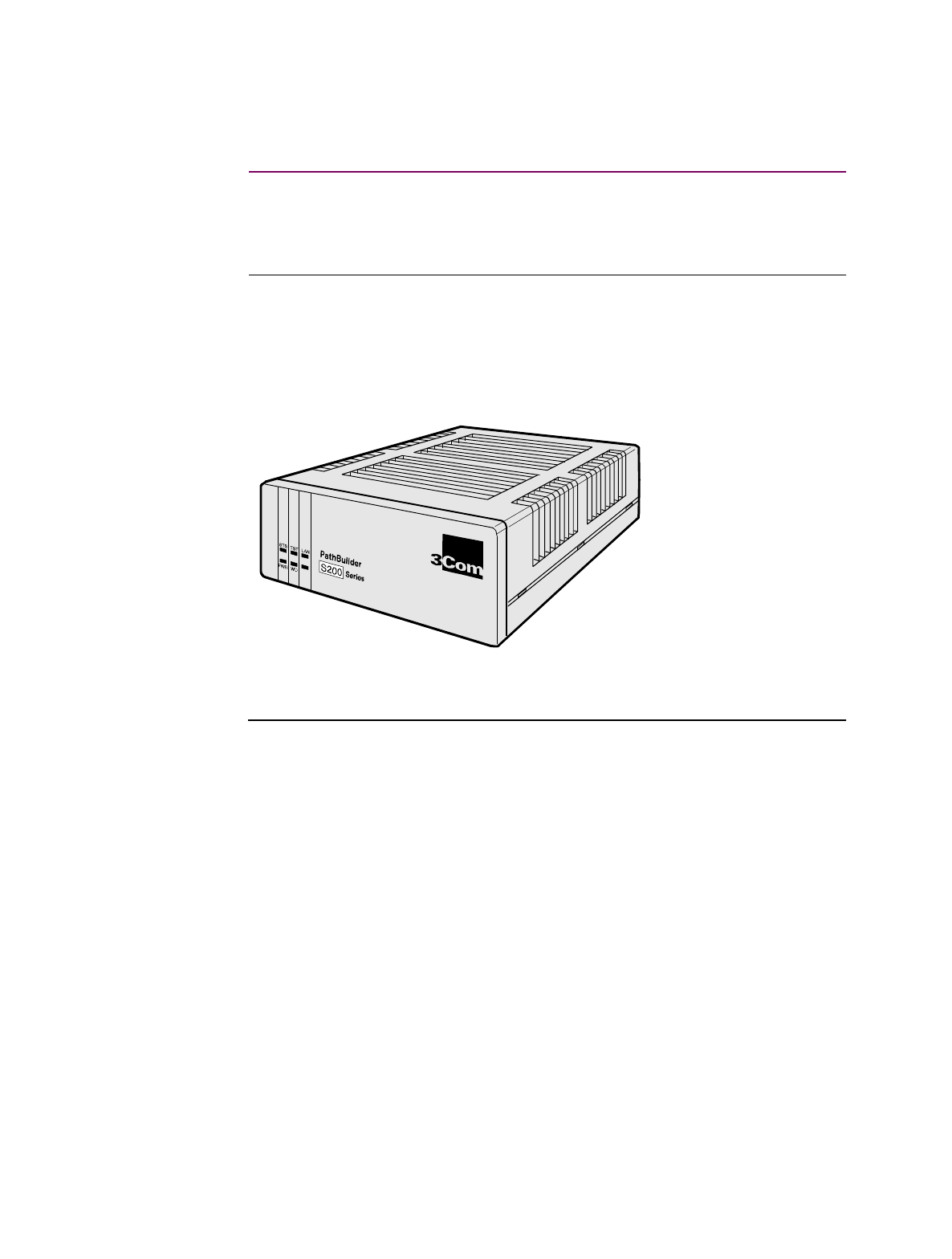
Introduction The 3Com PathBuilder S21x switch is a compact network access device for
connecting LAN and serial devices to public and private networks services such as
frame relay and X.25. The PathBuilder S21x switch is a desktop-size standalone
device supporting up to two optional daughtercards, as shown in Figure 1-1. Using
the optional daughtercards, the PathBuilder S21x switch offers a flexible and cost
effective solution for transporting data, voice, and video across a network.
Figure 1-1. The PathBuilder S21x Switch
®

1-2 About the PathBuilder S21x Switch
Features
Features
Standard Features The base PathBuilder S21x switch provides the following:
• External power supply
• Control Terminal Port (CTP) for local and remote configuration and
management
• Ethernet interface (10BaseT)
• One Serial DIM Port
• Two daughtercard slots
• 2 MB FLASH and 4 MB DRAM
CTP Port Port 4 can be used as a Control Terminal Port (CTP) for configuration, reporting, and
troubleshooting the PathBuilder S21x switch. To set Port 4 as CTP, put the front
panel dip switch 4 into the UP position. To access the CTP you must also configure
your terminal or terminal emulation software, to VT100, 9600 bps, 8 bit, no parity, 1
stop bit.
Dual Daughtercard
Slots The PathBuilder S21x switch comes with two slots to support optional
daughtercards. This permits easy future expansion of the product.
Operating Software Operating software is compressed in FLASH memory and loaded into DRAM for
operation. The PathBuilder S21x switch supports these Applications Ware packages:
• IP Applications Ware Package
• IP & IPX Applications Ware Package
• SNA Applications Ware Package
• Serial Protocol Applications Ware Package
• Multiservice Applications Ware Package
• Multimedia Applications Ware Package
See the Software Release Notes accompanying your PathBuilder S200 series switch
unit for more information on the software available for the PathBuilder S21x switch.

About the PathBuilder S21x Switch 1-3
Features
Daughtercard Functionality
Introduction The PathBuilder S21x switch is available with the optional components listed below
factory-installed or as separate add-in daughtercards.
• Voice Relay Daughtercard
• Dual FXS Voice Relay Daughtercard
• RemoteVu Daughtercard
• DSU Daughtercard
• DIM Daughtercard
• DRAM SIMMs
Refer to the PathBuilder S200 Series Switch Daughtercard Installation Manual
(T0020) for information on the installation of optional daughtercards.
Voice Relay
Daughtercard The PathBuilder S21x switch supports the Voice Relay Daughtercard. This
daughtercard supports one voice channel, using either an analog FXS or FXO
interface. Both interfaces use RJ11 connectors.
Dual FXS Voice
Relay
Daughtercard
The Dual FXS Voice Relay Daughtercard provides two FXS interface ports and
support one voice channel each. The FXS port uses RJ45 connectors.
RemoteVu
Daughtercard The PathBuilder S21x switch supports video over Frame Relay using the RemoteVu
daughtercard. The RemoteVu Daughtercard provides two BNC connector, video
ports accepting NTSC, PAL or SECAM video signal standards and an RJ-45, RS232/
485 camera control port used for Pan/Tilt/Zoom (PTZ) camera control.
DSU Daughtercard The DSU daughtercard functionality suits an extended range of 56 kbps
point-to- point DDS1 interfaces that conforms to AT&T 62310 or
ANSI T1E1.4/91-006.
The DSU is FCC Part 68 registered.
Diagnostic loopbacks from the telephone company are supported; local diagnostics
are activated from the CTP.

1-4 About the PathBuilder S21x Switch
Features
DIM Site
Daughtercard The DIM Site daughtercard provides optional V.24, V.35, V.36, or V.11 electrical
interfaces through a DB25 physical connector.
DSU DIM The PathBuilder S21x switch supports the DSU DIM.

About the PathBuilder S21x Switch 1-5
Features
Software Functionality
Introduction Depending on the operating software AppsWare package and optional daughtercard
installed the PathBuilder S21x switch can support the following functionality and
services.
Frame Relay & X.25
Service The PathBuilder S21x switch provides serial devices with economical Ethernet LAN
access into public or private Frame Relay WAN. Where frame relay services are not
yet available, the PathBuilder S21x switch can provide network access over X.25
services. When frame relay services becomes available, the PathBuilder S21x switch
can be easily configured and integrated to support frame relay. This fast migration
reduced network downtime and protects hardware investments.
RFC 877 and 1356 The PathBuilder S21x switch supports encapsulation of IP datagrams and other
network layer protocols over X.25 as specified in RFC 877 and RFC 1356. This
allows for interoperability with Front End Processors (FEPs) that support X.25 and
IP traffic as well as router vendors supporting RFC 877/1356.
RFC 1490 The PathBuilder S21x switch supports encapsulation of multiple protocols over
frame relay as specified by RFC 1490.
Multiprotocol
Support Support includes SDLC, Bisync, X.25, Async, IP/IPX, PPP, MLPPP, and Routing
and Bridging, as well as many other serial protocols. Refer to the Software Release
Notice which accompanied your unit for a complete listing of protocols supported by
the PathBuilder S21x switch.
1-6 About the PathBuilder S21x Switch
Target Application Environments
Target Application Environments
Introduction This section describes example applications for the PathBuilder S21x switch.
LAN and Legacy
Protocol over
Frame Relay
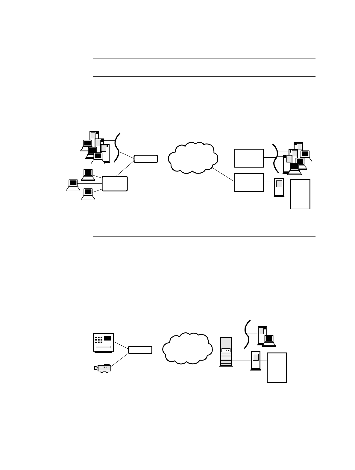
The PathBuilder S21x switch supports multiprotocol encapsulation of IP traffic and
legacy serial protocols over frame relay as specified by RFC 1490. As shown in
Figure 1-2, a SNA cluster controller connects to a serial port on the PathBuilder S21x
switch and the Ethernet LAN connects to the 10BaseT Ethernet port. The PathBuilder
S200 series switch is fully interoperable with third party routers via RFC 1490.
Figure 1-2. LAN and Legacy Protocol over Frame Relay
Video and Legacy
Protocols over
Frame Relay -
Banking
Application
As shown in Figure 1-3, the PathBuilder S21x switch can support encapsulation of
video and legacy protocol over frame relay. This use of PathBuilder S21x switch
suits banking applications such as Automated Bank Machines (ABMs). With Dial on
Demand software feature enabled, the PathBuilder S21x switch initiates a connection
only when there is data transfer, i.e. only for the duration of a bank transaction. The
RemoteVu Daughtercard can capture video and send video streams to the central
bank’s security system.
Figure 1-3. LAN and Legacy Protocol over Frame Relay
Third Party
Router
PB S200 Frame Relay
Ethernet
Cluster
Controller
Terminals
Ethernet
Third Party
Router
FEP
HOST
Frame Relay
Equipped with
RemoteVu
Daughtercard
PCs Running Host Video
Workstation Application
Central BankAutomated Teller Machine
S200
FEP
HOST
Video
Camera
Bank ATM
About the PathBuilder S21x Switch 1-7
Target Application Environments
Branch Office to
Central Office over
Frame Relay
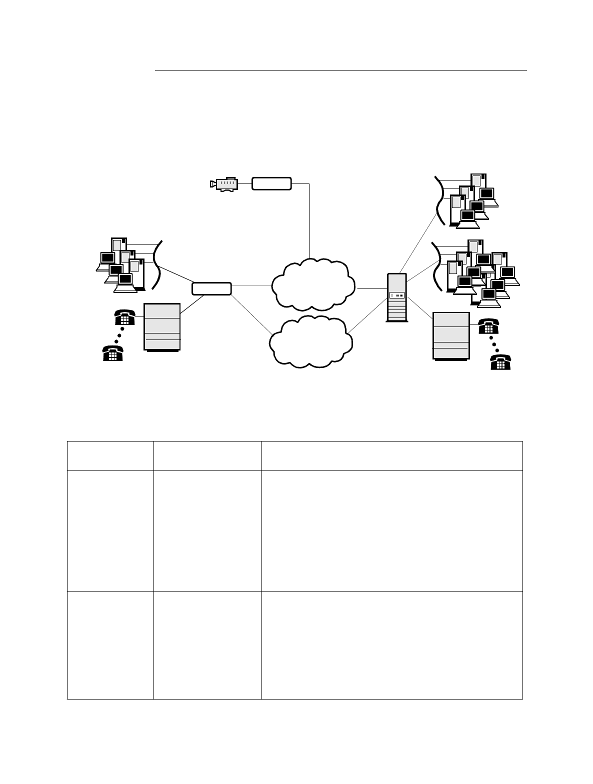
The PathBuilder S21x switch offers an ideal solution for branch office to central
office connectivity over a private or public frame relay network as shown in
Figure 1-4.
Figure 1-4. PathBuilder S21x switch supporting Voice and Video over
Frame Relay
Frame Relay
Equipped with DSU DIM,
Voice Relay, and ISDN
Daughtercards
Branch Office
Security Monitoring
at Branch Office
Video Camera
Ethernet
PCs Running Host Video
Workstation Application
Central Office
ISDN
Equipped with
RemoteVu Daughtercard
PB S200
Ethernet
PBX
PB S200
PBX
Application
Type Daughtercard
Used Application Description
Branch access to
Central Office DSU DIM and Voice
Relay Daughtercards The PathBuilder S21x switch supports voice, video and
data traffic between the branch and central office over pri-
vate or public frame relay network. The Voice Relay
Daughtercard supports telephones, PBX, and faxes.
Connect a telephone or PABX to one FXS port on the
Voice Relay Daughtercard and all branch telephones have
access to the central office PBX. This eliminates long
distance telephone charges between the branch and
central office.
Security
Monitoring at
Branch Office
RemoteVu and DSU
Daughtercards
The PathBuilder S21x switch equipped with a RemoteVu
Daughtercard provides security surveillance and remote
monitoring of the branch office location from the central
office. The RemoteVu Daughtercard packetizes video
stream in IP and sends the data over the frame relay.
Security personnel at the central office can control the
branch office video camera from a PC running the Host
Video Workstation application.

1-8 About the PathBuilder S21x Switch
Target Application Environments
Installing the PathBuilder S21x Switch Hardware 2-1
Chapter 2
Installing the PathBuilder S21x Switch Hardware
Overview
Introduction This chapter covers the installation of PathBuilder S21x switch hardware.
Follow These Steps This table lists the steps you need to perform and shows you where to look for
information on installing the PathBuilder S21x switch:
Warning The following special notices apply to all equipment handling procedures in this
manual.
Warning
Ports capable of connecting to ports on other apparatus are defined as Safety Extra
Low Voltage (SELV). To conform with EN60950, ensure that these ports are only
connected to ports of the same type on other apparatus.
Avertissement
Les ports qui sont susceptibles d’être connectés à des équipements sont désignés
comme TBTS. Pour garantir la conformité à la norme EN 60950, n’interconnecte
ces ports qu’avec des ports du même type sur des autres matériels.
Warnung
Anschlusse, die mit anderen Geraten verbindet werden konnen, sind als SELV
beschrieben. Um Konformitat mit EN 60950 zu versichern, sichern Sie es, daß diese
Anschlusse nur mit den des selben Type auf anderen Geraten verbindet werden.
Step To Perform This Action See This Procedure
1Check the contents of the
shipping package to make sure
everything is included.
“Checking Your Shipment Contents”
section on page 2-2.
2Choose a site for the Path-
Builder S21x switch. “Choosing a Site” section on page 2-3.
3Connect cables for the Path-
Builder S21x switch. “Cabling the PathBuilder S21x Switch”
section on page 2-5.
4Set the front panel dip switches
if required. “Front Panel Dip Switches” section on
page 2-10
5Installing Optional Daughter-
card. “Installing Optional Daughtercards”
section on page 2-11
6Installing or Removing the Lith-
ium Battery “Installing or Removing the Lithium
Battery” section on page 2-12
2-2 Installing the PathBuilder S21x Switch Hardware
Checking Your Shipment Contents
Checking Your Shipment Contents
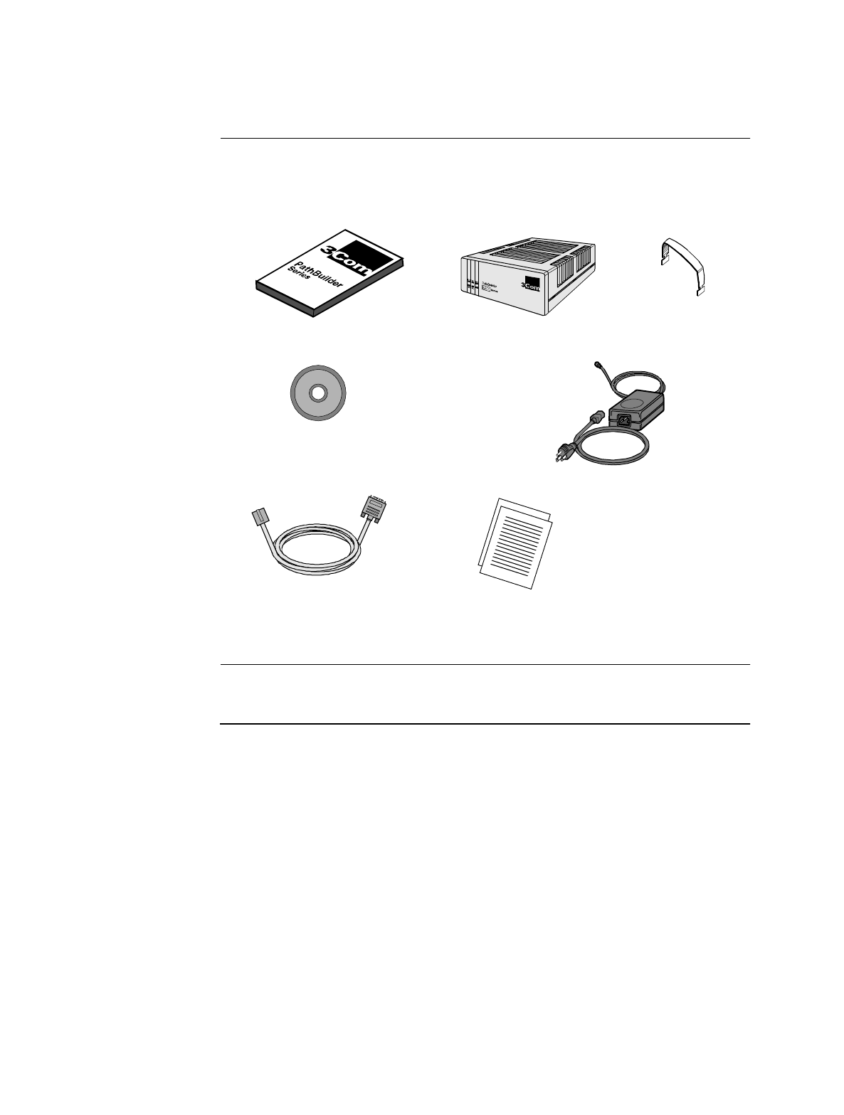
List of Contents Before you install the PathBuilder S21x switch hardware, make sure your shipment
contents are complete. Inside your shipping carton, you should find the contents
shown in Figure 2-1.
Figure 2-1. PathBuilder S21x Switch Shipment Contents
In Case of Damage
or Missing Parts If the equipment is damaged, contact the shipper. If you have additional concerns
about damaged or missing parts, contact your nearest 3Com representative.
Pathbuilder S21x switch
PathBuilder S21x Installation Manual
RJ45 to DB25 CTP Cable
PathBuilder S200 Series User Guides CD-ROM
External Power Supply and Cable
DIM Extraction Tool
Software Release Notice
®
®
Installing the PathBuilder S21x Switch Hardware 2-3
Choosing a Site
Choosing a Site
Introduction This section describes how to choose a site for the PathBuilder S21x switch.
Choosing a Site Choose a site within an appropriate distance of a power source. The selected site
should be free of accumulated dust and environmental extremes.
Caution
All PathBuilder S200 series switch products should be used in environments
designed for computers and electronic equipment. In areas susceptible to lightning,
take precautions to prevent damage to electronic equipment. Contact your telephone
company or an electronic accessories vendor for information on lightning protection
equipment. If you experience problems caused by surges from lightning, install
appropriately rated surge suppressors on power and data lines connected to your
PathBuilder S200 series switch.
Mise en Garde
Tous les produits PathBuilder S200 series switch doivent être utilisés dans des
environnements conçus pour les ordinateurs et équipements électroniques. Dans les
zones sujettes à la foudre, prenez soin de protéger l’équipement électronique contre
tout dommage. Contactez votre compagnie de téléphone ou un vendeur d’accessoires
électroniques pour de plus amples informations sur les équipements de protection
contre la foudre. Si vous avez des problèmes engendrés par des surtensions dues à la
foudre, installez des protections contre les surintensités appropriées sur les lignes
d’alimentation et de données connectées à votre produit PathBuilder S200 series
switch.
Vorsicht
Alle PathBuilder S200 Series Switch-Produkte sollten in für Computer und
elektronische Geräte geeigneten Umgebungen verwendet werden. In durch
Blitzschlag gefährdeten Gebieten sollten Vorsichtsmaßnahmen zum Schutz von
elektronischen Geräten ergriffen werden. Informationen über Schutzeinrichtungen
gegen Blitzschlaggefahr erhalten Sie von Ihrer Telefongesellschaft oder vom
Einzelhandel für Elektrozubehör. Wenn Sie durch Blitzeinwirkung verursachte
Spannungsstörungen feststellen, installieren Sie einen ausreichend abgesicherten
Spannungsableiter an den Strom- und Datenleitungen, die mit dem PathBuilder S200
Series Switch-Produkt verbunden sind.
Power Source Depending on your application and the country in which the PathBuilder S21x
switch will operate, a power source must be a grounded 100 to 240 VAC outlet.
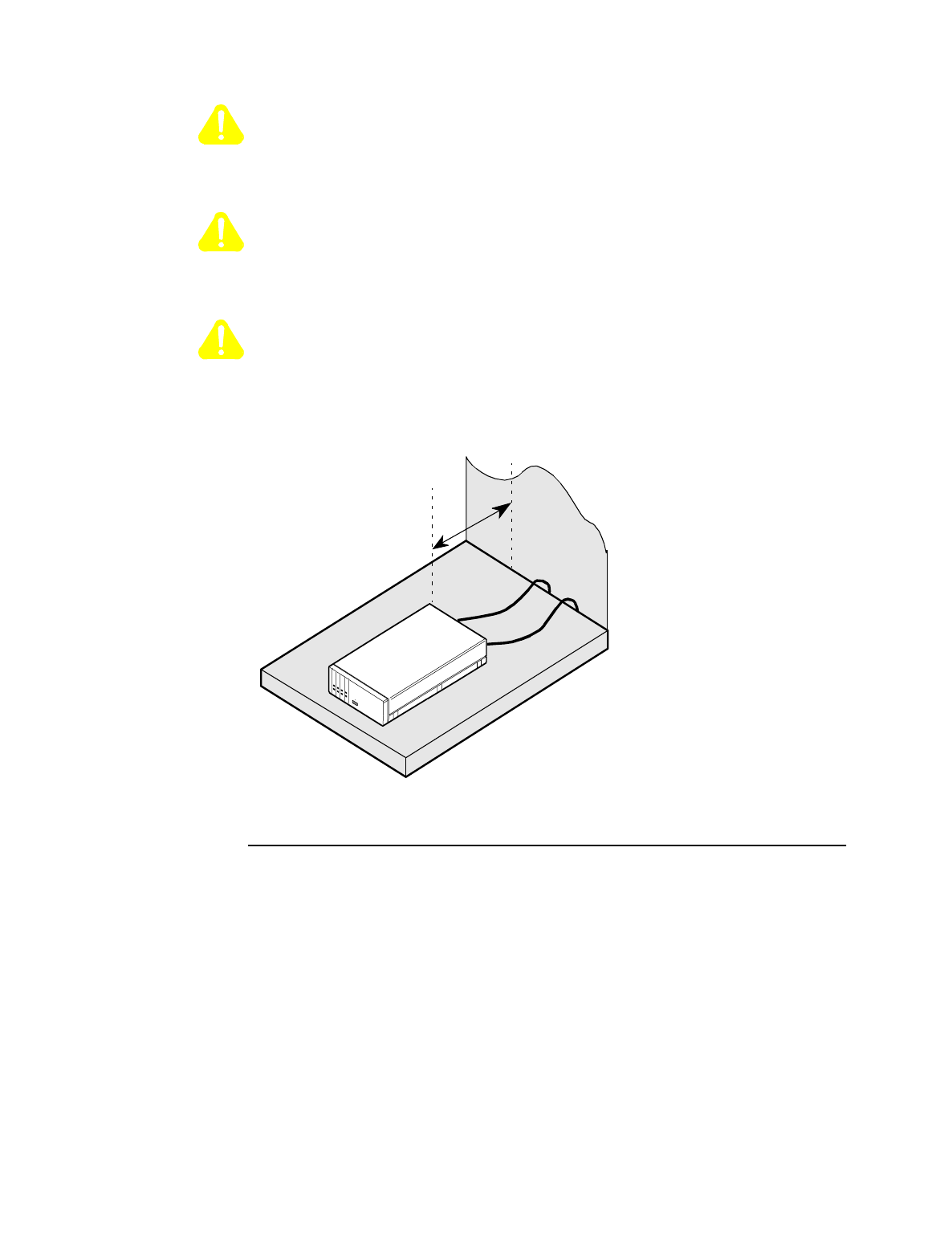
Cable Clearance/
Air Circulation Allow at least 12 inches (30.5 cm) in back of the unit for interfacing cable clearance
and air circulation, as shown in Figure 2-2.
2-4 Installing the PathBuilder S21x Switch Hardware
Choosing a Site
Caution
To avoid overheating the unit’s circuitry, you should never place anything on top of
the unit, within 1 inch (2.5 cm) of the ventilation slots on the front panel, or within
12 inches (30.5 cm) of the back of the unit.
Mise en Garde
Afin d’éviter toute surchauffe des circuits de l’unité, ne placez aucun objet sur l’unité
à moins de 2,5 cm (1 pouce) des conduits de ventilation du panneau avant et à moins
de 30,5 cm (12 pouces) de l’arrière de l’unité.
Vorsicht
Zur Vermeidung einer Überhitzung der Geräteschaltkreise sollten Sie keine
Gegenstände auf dem Gerät plazieren. Zu den Entlüftungsöffnungen der
Vorderabdeckung sollte ein Abstand von 2,5 cm und zur Rückseite des Gerätes von
30,5 cm eingehalten werden.
Figure 2-2. Proper Cable and Air Clearance
Minimum
12 inches
(30.5 cm)
Do Not Place
Anything on Top
of Unit
Installing the PathBuilder S21x Switch Hardware 2-5
Cabling the PathBuilder S21x Switch
Cabling the PathBuilder S21x Switch
Introduction After unpacking the PathBuilder S21x switch, you can connect the cables to
complete the hardware installation.
PathBuilder S21x
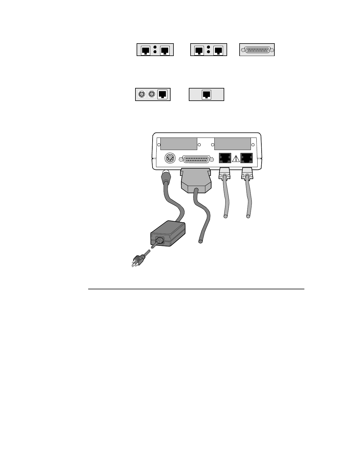
Switch Rear Panel Figure 2-3 illustrates the rear panel of the PathBuilder S21x switch, optional
daughtercards, and the locations of cables that must be connected.
Caution
Connectors showing this symbol must not be connected to Published Switched
Telephone Networks (PSTN).
Mise en Garde
Les connecteurs marqués de ce symbole ne doivent pas être connectés au réseau
téléphonique commuté public (RTCP).
Vorsicht
Stecker mit diesem Symbol dürfen nicht an das öffentliche Telefonnetz (PSTN)
angeschlossen werden.
2-6 Installing the PathBuilder S21x Switch Hardware
Cabling the PathBuilder S21x Switch
Figure 2-3. PathBuilder S21x Switch Rear Panel and Cable Connections
Power Supply
CTP Cable to an ASYNC terminal.
10BaseT
Ethernet
Cable
PORT 2
PORT 3
POWER CTP 10B-T
PORT 1
DIM Site
DSU Daughtercard
RJ48S connector for DSU
FXS FXOLOC
REM
Voice Relay
Daughtercard Daughtercard
DB25 connector for
V.24, V.35, V.36, V.11,
and DSU DIM
RJ11 connector for
FXS and FXO Ports
DB25 connector for
V.24, V.35, V.36,
V.11, and DSU DIM
FXS FXSLOC
REM
Dual FXS Daughtercard
Two RJ11 connectors
for FXS Ports
RemoteVu Daughtercard
2 BNC and 1 RJ45
connector
PORT 1PORT 2

Installing the PathBuilder S21x Switch Hardware 2-7
Cabling the PathBuilder S21x Switch
Cables
Introduction This section describes cables required to connect to the PathBuilder S21x switch.
Port
Characteristics and
Cable
Requirements
The table below lists the port characteristics, connector and cable requirements.
Port Connector Interface Cable Required Speed DCE/DTE
1 DB25 DIM Site Daugh-
tercard
V.1 1, V. 24 , V.35,
V.3 6
DB25-to-DB25
Cable V.11, V.35 and V.36 -
Max. sync speed 2
mpbs
V.24 - Max. sync
speed 80 kpbs, Max
async speed 115.2
kbps
Selectable
DIM Site Daugh-
tercard
DSU DIM
DSU/EIM Cable
Assembly and
Lease Line Telco
Cable shipped with
Integral DSU only
DSU - 56 kbps DTE DSU
RJ48S DSU
Daughtercard
DSU Telco Cable
shipped with DSU
Daughtercard
DSU -56 kbps DTE DSU
RJ11 Voice Relay
Daughtercard
RJ11-to-RJ11
Cable N/A N/A
RJ45 S/T
Daughtercard
RJ45-to-RJ45
Cable Either 56 or 64 kbps
for each B Channel
and 9.6 kbps for the
D Channel
N/A
BNC video
connector RemoteVu
Daughtercard BNC-to-BNC
Cable
RJ45
connector RemoteVu
Daughtercard RJ45-to-RJ45
Cable
RJ45 Dual FXS
Daughtercard RJ45-to-RJ45
Cable

2-8 Installing the PathBuilder S21x Switch Hardware
Cabling the PathBuilder S21x Switch
2 DB25 DIM Site Daugh-
tercard
V.11, V.24, V.35,
V.36
DB25-to-DB25
Cable V.11, V.35 and V.36 -
Max. sync speed 2
mpbs
V.24 - Max. sync
speed 80 kpbs, Max
async speed 115.2
kbps
Selectable
DIM Site Daugh-
tercard
DSU DIM
DSU/EIM Cable
Assembly and
Lease Line Telco
Cable shipped with
Integral DSU only
DSU - 56 kbps DTE DSU
RJ48S DSU
Daughtercard
DSU Telco Cable
shipped with DSU
Daughtercard
DSU -56 kbps DTE DSU
RJ11 Voice Relay
Daughtercard
RJ11-to-RJ11
Cable N/A N/A
BNC video
connectors RemoteVu
Daughtercard BNC-to-BNC
Cable
RJ45 con-
nector RemoteVu
Daughtercard RJ45-to-RJ45
Cable
RJ45 Dual FXS
Daughtercard RJ45-to-RJ45
Cable
3 DB25 V.11, V.24, V.35,
V.36 DIM DB25-to-DB25
Cable V.11, V.35 and V.36 -
Max. sync speed 2
mpbs
V.24 - Max. sync
speed 80 kpbs, Max
async speed 115.2
kbps
Selectable
Integral DSU
DIM DSU/EIM Cable
Assembly and
Lease Line Telco
Cable shipped with
Integral DSU only
DSU - 56 kbps
4 RJ45 CTP Port RJ45-to-DB25
CTP Cable shipped
with PathBuilder
S200 series switch
unit
Max. async speed
115.2 kbps
DCE
Port Connector Interface Cable Required Speed DCE/DTE
Installing the PathBuilder S21x Switch Hardware 2-9
Cabling the PathBuilder S21x Switch
Cable and
Connector Pinouts For more information on cable and connector pinouts, refer to Appendix B,
PathBuilder S21x Switch Cabling or to the Daughtercard Installation Guide for
information on the optional daughtercards.
Control Terminal
Port Cable Use an RJ45 (male) to DB25 (female) cable that comes with the PathBuilder S21x
switch to connect to the Control Terminal Port (CTP). The PathBuilder S21x switch
defaults this port to 9.6 kbps, 8 bits, no parity, 1 stop bit.
Note
If you plan to use a personal computer to configure the PathBuilder S21x switch,
you may need to purchase a DB25 (male) to DB9 (female) adapter for the serial
port of your personal computer. The serial ports on most personal computers
require DB9 connectors.
10BaseT Ethernet
Cable Follow these guidelines for 10BaseT cable connections:
• If you are connecting to a 10BaseT Hub, use a standard UTP cable
(RJ45 to RJ45).
• If you are connecting directly to a personal computer or Workstation LAN
card, use the 10BaseT crossover cable shipped with your PathBuilder S21x
switch.
LAN RJ45 10BaseT 10BaseT Cross-
over cable
or
standard UTP cable
(RJ45-to-RJ45)
10Mbps
Port Connector Interface Cable Required Speed DCE/DTE
Interface Connector
U interface (North America) RJ11
S/T interface (Europe) RJ45
2-10 Installing the PathBuilder S21x Switch Hardware
Front Panel Dip Switches
Front Panel Dip Switches
Introduction This section describes the front panel dip switches on the PathBuilder S21x switch.
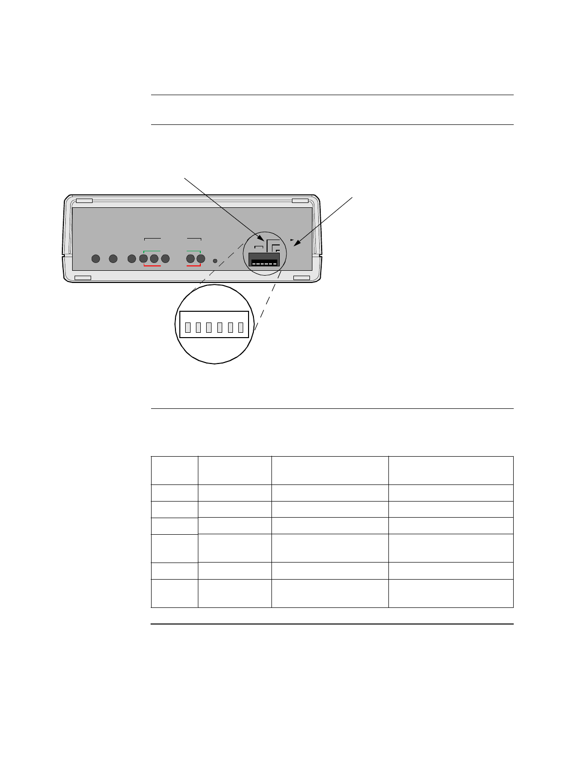
Front Panel
Switches Figure 2-4 illustrates the switches found behind the front panel of the PathBuilder
S21x switch.
Figure 2-4. PathBuilder S21x Switch Front Panel Switches
Front Panel DIP
Switch Setting The six DIP switches on the front panel are defined as follows:
POWER
DATA IN
CTP-- PORT 4
DIAG.
DFLT NODE
3 3
TM
RI
Port
MB
RESET
STATUS TEST
WATCHDOG
LAN 4 3 2 1
Default Node
To reset all configurable parameters, put
switch in up position and Power Cycle (or
Reset), then put switch in down position
and Power Cycle (or Restart) again.
Control Port Switch
Defaults Port 3 to 9600 bps 8N1.
123456
DATA OUT
PORT
Switch
Posn. Switch
Name Down Up
1RI/TM Pin 22 - Ring Indicator DCE Test Mode Input
2MB/TM Pin 22 - Make Busy DTE Test Mode Input
3N/A N/A N/A
4CTP-Port 4 Normal operation Configure Port 4 as PAD
port
5DIAG Normal operation Execute diagnostics
6DFLT-NODE Normal operation Reset CMEM
configuration
Installing the PathBuilder S21x Switch Hardware 2-11
Installing Optional Daughtercards
Installing Optional Daughtercards
Optional
Daughtercards The PathBuilder S21x switch supports the following optional daughtercards:
• Voice Relay Daughtercard
• Dual FXS Voice Relay Daughtercard
• RemoteVu Daughtercard
• DSU Daughtercard
• DIM Site Daughtercard
• Motherboard DIM Option
• DRAM SIMM Option
These daughtercards can be installed either in the factory or on-site. Refer to the
PathBuilder S200 Series Daughtercard Installation Guide (Part Number T0020) for
complete daughtercard installation instructions.
Caution
On-site installation of these optional daughtercards should be undertaken by trained
service technicians.
Mise en Garde
L’installation de ces cartes fille optionnelles doit être effectuée par des techniciens
expérimentés.
Vorsicht
Die Installation vor Ort dieser optionalen Zusatzkarten sollte von geschulten
Kundendiensttechnikern durchgeführt werden.
2-12 Installing the PathBuilder S21x Switch Hardware
Installing or Removing the Lithium Battery
Installing or Removing the Lithium Battery
Introduction This section explains how to replace the real time battery. The PathBuilder S21x
switch uses a lithium battery on the motherboard to maintain the node’s real-time
clock. The battery is not used to store the configuration memory.
You need to install a battery under the following conditions:
• before the battery runs down
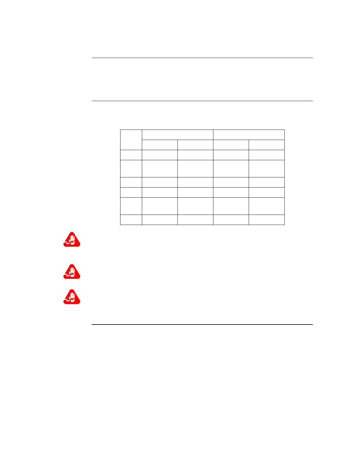
Warning
Only qualified service personnel should perform the procedure described in this
section. If the battery is installed incorrectly, it could explode after the PathBuilder
S200 series switch product is powered up, damaging the unit.
Avertissement
Seules des personnes qualifiées peuvent mettre en pratique les procédures décrites
dans cette section. Si la batterie n’est pas correctement installée, elle risque
d’exploser après la mise en marche du produit PathBuilder S200 series switch et
d’endommager l’unité.
Warnung
Die in diesem Abschnitt aufgeführten Vorgänge sollten ausschließlich von
qualifiziertem Servicepersonal durchgeführt werden. Wenn die Batterie
unsachgemäß installiert wird, kann sie nach dem Einschalten des PathBuilder S200
Series Switch-Produkts explodieren und das Gerät beschädigen.
Note
After installing the battery, set the PathBuilder S21x switch’s date and time. This
is done via the CTP in the Update System Parameter menu.
Battery Type Replace the lithium battery with lithium coin cell type CR2032 only. These can be
obtained where watch batteries are sold.
Battery Disposal Dispose of the battery in compliance with applicable local regulations.
Routine Battery
Replacement The lithium battery should be replaced every two years. Follow the instructions in
Figure 2-6 to replace the battery.
Installing the PathBuilder S21x Switch Hardware 2-13
Installing or Removing the Lithium Battery
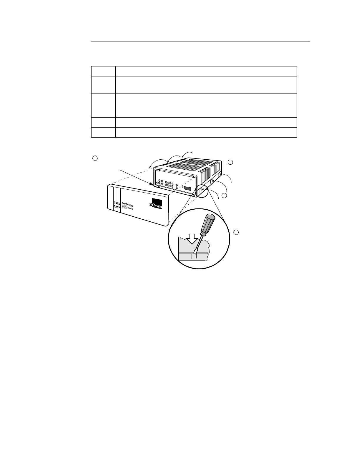
Removing the Top
Cover Refer to Figure 2-5 when removing the top cover and front panel and follow these
steps:
Figure 2-5. Removing Top Cover and Front Panel on
PathBuilder S21x Switch
Step Action
1Open front panel door by using a downward motion to pull it toward
you and off.
2Insert a flat-head screwdriver in the slot above each of the six snap
hinges on the sides of the unit and push downward. The hinges snap
out toward you.
3Repeat Steps 1 and 2 for the remaining hinges.
4Lift off the top cover.
Insert a flat-head screwdriver in the
slot above each of the six snap
hinges on the sides of the unit and
push downward. The hinges snap
out toward you.
1
2
3
4
Release hinges
on each side.
Open and remove front
panel by unsnapping the
panel from its tabs. Repeat for all six hinges
®
2-14 Installing the PathBuilder S21x Switch Hardware
Installing or Removing the Lithium Battery
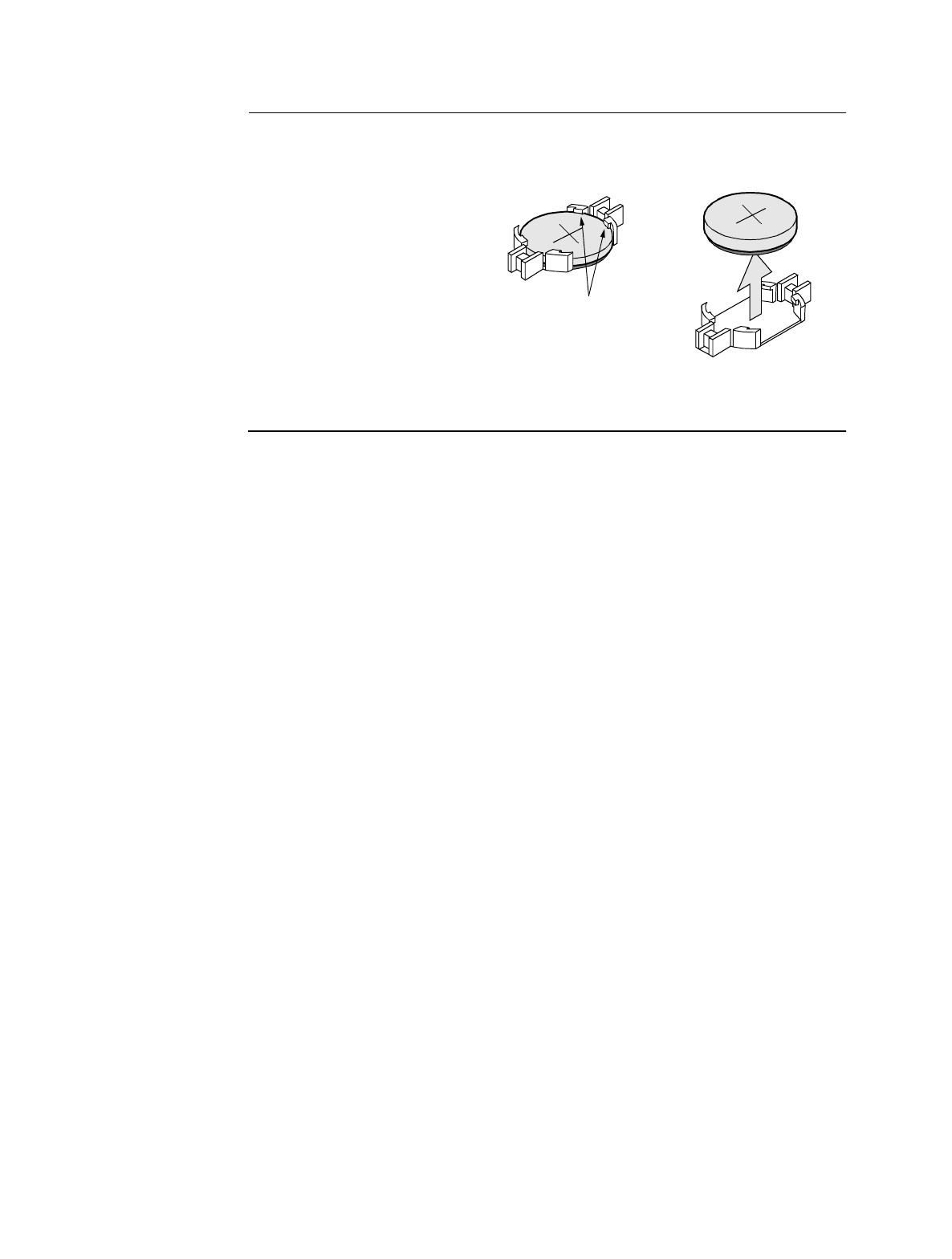
Removing/
Installing the
Battery
Figure 2-6 shows how to install and replace the battery.
Figure 2-6. Replacing the Battery
Retaining Tabs
Battery Holder
Battery
To remove the battery:
Using your fingers, push the retaining
tabs aside and pry the battery out of the
holder.
To install the battery:
Place the battery in the holder, with the
positive (+) side up, and press down until
the retaining tabs click into place.

Powering on the PathBuilder S21x Switch 3-1
Chapter 3
Powering on the PathBuilder S21x Switch
Overview
Introduction This chapter describes
• powering up the PathBuilder S21x switch
• interpreting LED display for power up diagnostics
• accessing the CTP
3-2 Powering on the PathBuilder S21x Switch
Powering On The PathBuilder S21x Switch
Powering On The PathBuilder S21x Switch
Introduction This section describes the sequence of events when you power up the PathBuilder
S21x switch.
Powering On the
PathBuilder S21x
Switch
The PathBuilder S21x switch does not have a power switch on the unit. Follow these
steps to power on the PathBuilder S21x switch:
Warning
When powering down the unit, you should always unplug the power cord at the
power supply outlet. Do not remove the power cord from the back of the unit.
Avertissement
Lors de l’arrêt de l’unité, débranchez toujours le cordon d’alimentation du bloc
d’alimentation. Ne le débranchez pas de l’arrière de l’unité.
Warnung
Nach dem Abschalten des Gerätes sollten Sie immer den Netzstecker des Gerätes aus
der Steckdose ziehen. Entfernen Sie nicht das Netzkabel von der Geräterückseite.
Warning
Hazardous voltage from the telecommunications network may be accessible on un-
earthed units. Disconnect all telecommunications cables before removing the main
lead from the power supply.
Avertissement
Des tensions dangereuses provenant des réseaux de télécommunication peuvent être
présentes sur des unités qui ne sont pas reliées à la terre. Déconnectez tous les câbles
de télécommunication avant de retirer le câble de secteur du bloc d’alimentation.
Warnung
An nicht geerdeten Geräten können gefährliche Spannungen vom
Telekommunikationsnetz anliegen. Trennen Sie alle Kabelverbindungen zum
Telekommunikationsnetz, bevor Sie das Hauptnetzkabel aus der Steckdose ziehen.
Step Action
1Plug the DC output cable of the power supply into the power socket on
the PathBuilder S21x switch back panel.
2Connect the power cord to the power supply outlet.
Powering on the PathBuilder S21x Switch 3-3
Powerup Diagnostics
Powerup Diagnostics
Introduction This section describes diagnostics that run automatically when you power up the
PathBuilder S21x switch.
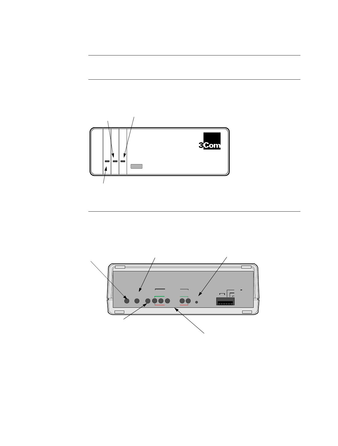
Front Cover LEDs The three front cover LEDs on the PathBuilder S21x switch help you follow the
progress of the unit’s powerup. Figure 3-7 shows the front cover.
Figure 3-7. Front Panel of the PathBuilder S21x Switch
Detailed Front
Panel LEDs Figure 3-8 illustrates the detailed front panel LEDs located behind the front cover.
Figure 3-8. Detailed Front Panel LEDs
TST
PWR STS
Power
WD
®
PathBuilder
Series
S200
Status Test Watchdog
POWER
DATA IN
CTP-- PORT 4
DIAG.
DFLT NODE
3 3
TM
RI
Port
MB
RESET
STATUS TEST
WATCHDOG
LAN 4 3 2 1
DATA OUT
PORT
Watchdog -GREEN
On: Hardware or software failure. Press
Reset or Power Cycle to clear LED.
Off: Processor OK.
Test - RED
Indicates status of test results.
On: Test Failed
Off: Normal Condition
Flashing:Test in Progress
Data Out - GREEN
On: Data Leaving Port = SPACE
Off: Data Leaving Port = MARK
Data In - RED
On: Data Entering Port = SPACE
Off: Data Entering Port = MARK
Status - GREEN
On: Software Running
Off: Software Not Running (Hardware Fault)
Flashing (Slow):Software Download in Progress
Power On - GREEN
Power is on and all DC Voltages
are within specifications. Reset
Resets (restarts) the unit.

3-4 Powering on the PathBuilder S21x Switch
Powerup Diagnostics
Power Up
Sequence When the PathBuilder S21x switch power cord is plugged into the power supply
outlet, you will see the following powerup sequence:
Hardware Failure If the TEST light turns on and remains on, one or more of the diagnostic tests have
failed, indicating there is a hardware problem. Contact 3Com for possible repairs to
your PathBuilder S21x switch.
Diagnostic Failure If the TEST light does not blink at all, but the Status light is on, the diagnostic
software image is corrupted. Perform a download of the software option bundle.
Powerup Failure If the STATUS light blinks continuously, at a constant rate, the software bundle in
Flash memory is corrupted. Perform a cold load of the software option bundle. See
the Software Installation and Coldloading Manual (Part No. T0028) for more
information.
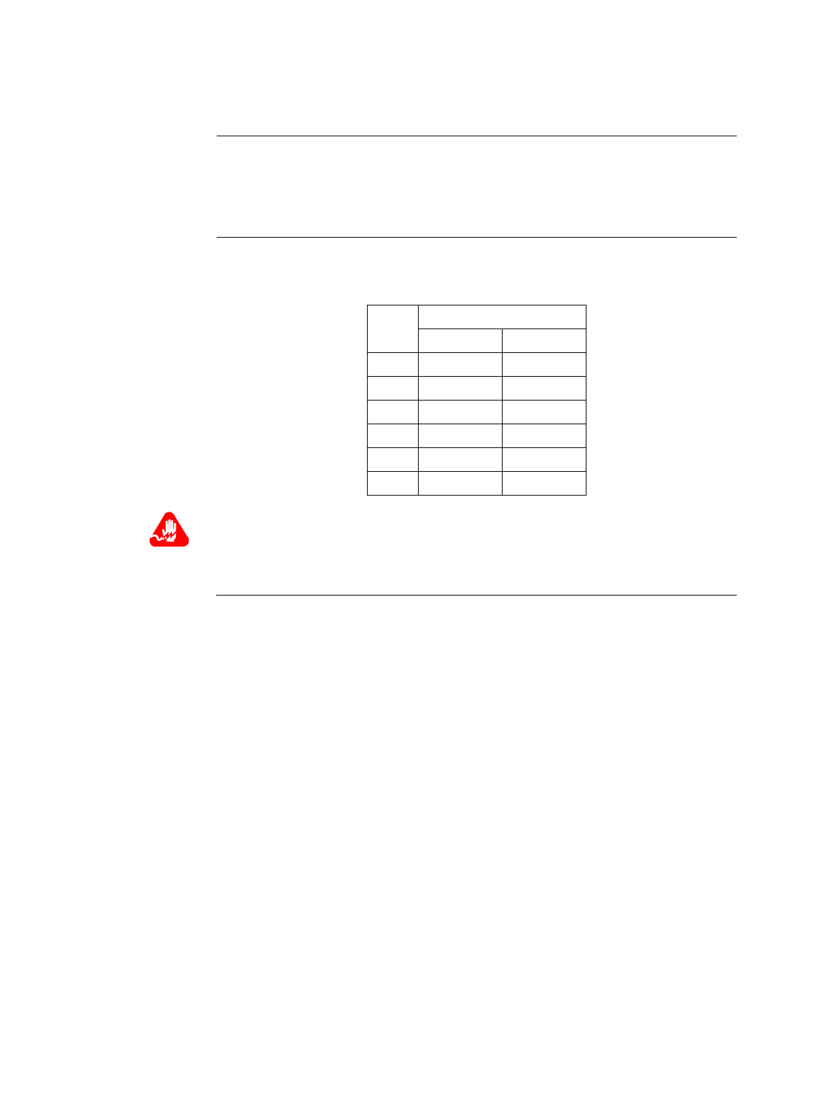
Stage when... ...this indicates
1POWER (GREEN) lights
turns on. PathBuilder S200 series switch is
receiving power.
2TEST (GREEN) comes on
and blinks five times Diagnostics executes for 30 seconds.
3STATUS (GREEN) comes on
and blinks at slow rate.
TEST/WATCHDOG
(ORANGE) light also remain
on.
Indicates software is being downloaded
from FLASH.
4STATUS (GREEN) light
stays off for up to 10 seconds,
then turns green.
Software is initializing your system
configuration.
Powering on the PathBuilder S21x Switch 3-5
Accessing the Control Terminal Port
Accessing the Control Terminal Port
Introduction Once you have powered on the PathBuilder S21x switch, you can access the Control
Terminal Port from the PC or terminal attached to the CTP port.
Note
This section does not provide all information about accessing the CTP. For more
information on accessing and using the CTP refer to the Basic Configuration
Manual (Part Number T0113).
Procedure Follow these steps to access the PathBuilder S21x switch CTP Main menu:
Note
This procedure assumes that a PC or terminal is connected to the PathBuilder
S21x switch using the CTP access cable.
CTP Access Via
Remote Telnet Another way to connect to the CTP, after the node is configured and operational, is to
access remotely via your established IP network by telneting into the node from an
IP network-based personal computer or workstation. You can connect to the CTP by
entering atds0 <CR> after the PathBuilder S21x switch outputs the OK prompt.
CTP Access Via
Remote X.25 or
Frame Relay
Network
If the PathBuilder S21x switch is operating in an X.25 network, or if Frame Relay
Annex-G is used to connect with other 3Com PathBuilder S200 series switches, you
can access the PathBuilder S200 series switch CTP remotely by making a Switched
Virtual Circuit (SVC) call to the node and specifying subaddress 98.
Step Action
1Set your terminal, or terminal emulation software, to VT100, 9600 bps,
8 bit, no parity, 1 stop bit.
2 Type <CR> until either an asterisk (*) or the OK prompt appears.
3When you see OK, type atds0 <CR>. When you see the asterisk (*) type
.ctp.
The CTP banner will appear. If this banner does not appear, verify that
these steps have been followed correctly.
4Type <CR> at the password prompt, if no password has been set.


Specifications A-1
Appendix A
Specifications
Specifications
Introduction This section describes the physical and environmental specifications and power
requirements for the PathBuilder S21x switch product.
Hardware PathBuilder S21x switch products feature the following:
• 68360 processor
• 4 Mbytes DRAM (expandable to 8 or 12 Mbytes)
• 10Base T Ethernet
• Async Control Port
• 2.0 Mbytes of FLASH memory
• 2 optional daughtercard ports
• 1 configurable DIM port
Software The PathBuilder S21x switch supports these software applications ware:
• IP Applications Ware Package
• IP & IPX ApplicationsWare Package
• SNA Applications Ware Package
• Serial Protocol Applications Ware Package
• Multiservice Applications Ware Package
• Multimedia Applications Ware Package
Environmental The following environmental conditions are required:
• Operating temperature: 32° to 104°F maximum (0° to 40°C maximum)
• Storage temperature: -22° to +158°F (-30° to +70°C)
• Relative humidity: 5% to 95% (noncondensing)
Electromagnetic
Compatibility PathBuilder S21x switch products adhere to the following:
• FCC Part 15, Class B
• CISPR 22 and EN 55022, Class B
• AS 3548, Class B
• EN 50082-1

A-2 Specifications
Power
Requirements PathBuilder S21x switch typically has the following power requirements:
• 100 to 240 VAC nominal at 47 to 63 Hz
• 32 watts input power (64 VA)
• maximum input current 0.7 amps
Power Supply
Description PathBuilder S21x switch products are powered by a switch mode power supply with
22.5 watts maximum output power.
Safety PathBuilder S21x switch meets the following safety standards:
• EN60950
• CSA 950
• UL Listed per UL 1950
Physical PathBuilder S21x switch has the following measurements:
• Height: 2.75 in. (6.7 cm)
• Length: 6.7 in. (17 cm)
• Width: 9.5 in. (24.5 cm)
• Weight: 2.2 lb (1.0 kg)

PathBuilder S21x Switch Cabling B-1
Appendix B
PathBuilder S21x Switch Cabling
Overview
Introduction This Appendix identifies the cables and pinout requirements for the PathBuilder
S21x switch. The following cables are described in this appendix:
• CTP Access Cable
• Dual FXS Voice Relay Cable
• 10BaseT Crossover Cable
• RemoteVu Video Cables
• DSU Daughtercard Cable
• V.35/V.36 Cable
• V.11 Cable
• V.24 Cable
Daughtercard
Cable Information Cables for optional daughtercards are shipped with the daughtercards. If your
PathBuilder S21x switch is shipped with pre-installed daughtercards you will receive
the cables. For daughtercard installation and more cable information, please refer to
the PathBuilder S200 Series Daughtercard Installation Guide (Part Number, T0020).
Ordering Cables To order cables please contact a 3Com representative. In addition to the cables
listed above the following cables can be ordered:
• DB25 Male to M34 Female cable
• DB25 Male to M34 Male cable

B-2 PathBuilder S21x Switch Cabling
CTP Access Cable
CTP Access Cable
CTP Cable
Connector and
Pinout
Use the supplied RJ45/DB25 cable to connect to the CTP Port (Port 4) and perform
CTP operations such as coldloading software images into a PathBuilder S21x switch.
Port 4 is a DCE. This table identifies the pinout for this RJ-45 connector:
RJ45 Pin Signal Pin Connection
on DB25F
Adapter
1 (not connected) Request To Send (RTS) 4
2 DTE Ready (DTR) 20
3 Received Data (RXD) 3
4 (not connected) Data Carrier Detect (DCD) 8
5 Signal Ground 7
6 Transmitted Data (TXD) 2
7 Data Set Ready (DSR) 6
8 (not connected) Clear To Send (CTS) 5
PathBuilder S21x Switch Cabling B-3
Voice Relay Cable
Voice Relay Cable
Specification The voice relay cable shipped with the Voice Relay Daughtercard has the following
specification:
• Connectors: RJ11 to RJ11 Cable
• Color: Gray
Connector Pinout The RJ11 connectors for the FXO and FXS port have the following pinout:
Warning!
The FXS Interface should only be connected to an analog telephone handset and/or
fax machine.
Warning!
The FXO Interface should only be connected to an analog PBX line.
Warning!
The PathBuilder S200 series switch Voice Relay daughtercard has not been certified
for use in a PSTN.
Pin
No. FXS FXO
Name Function Name Function
1N/A N/A
2 N/A Aux B External
Handset
3 Loop B Line B
4 Loop A Line A
5 N/A Aux A External
Handset
6N/A N/A
B-4 PathBuilder S21x Switch Cabling
Dual FXS Voice Relay Cable
Dual FXS Voice Relay Cable
Specification The voice relay cable shipped with the Dual FXS Voice Relay Daughtercard has the
following specification:
• Connectors: RJ45 to RJ45 Cable
• Color: Gray
Connector Pinout The RJ45 FXS port have the following pinout:
Warning!
The FXS Interface should only be connected to an analog telephone handset and/or
fax machine.
Pin
No. FXS
Name Function
1N/A
2N/A
3 Loop B
4 Loop A
5N/A
6N/A
PathBuilder S21x Switch Cabling B-5
10BaseT Crossover Cable
10BaseT Crossover Cable
Specifications The 10BaseT cable shipped with the PathBuilder S21x switch has the following
specifications:
• Cable Type: Category 3 or better
• Connectors: RJ45 to RJ45
• Color: Gray
• Part Number: 61798-01
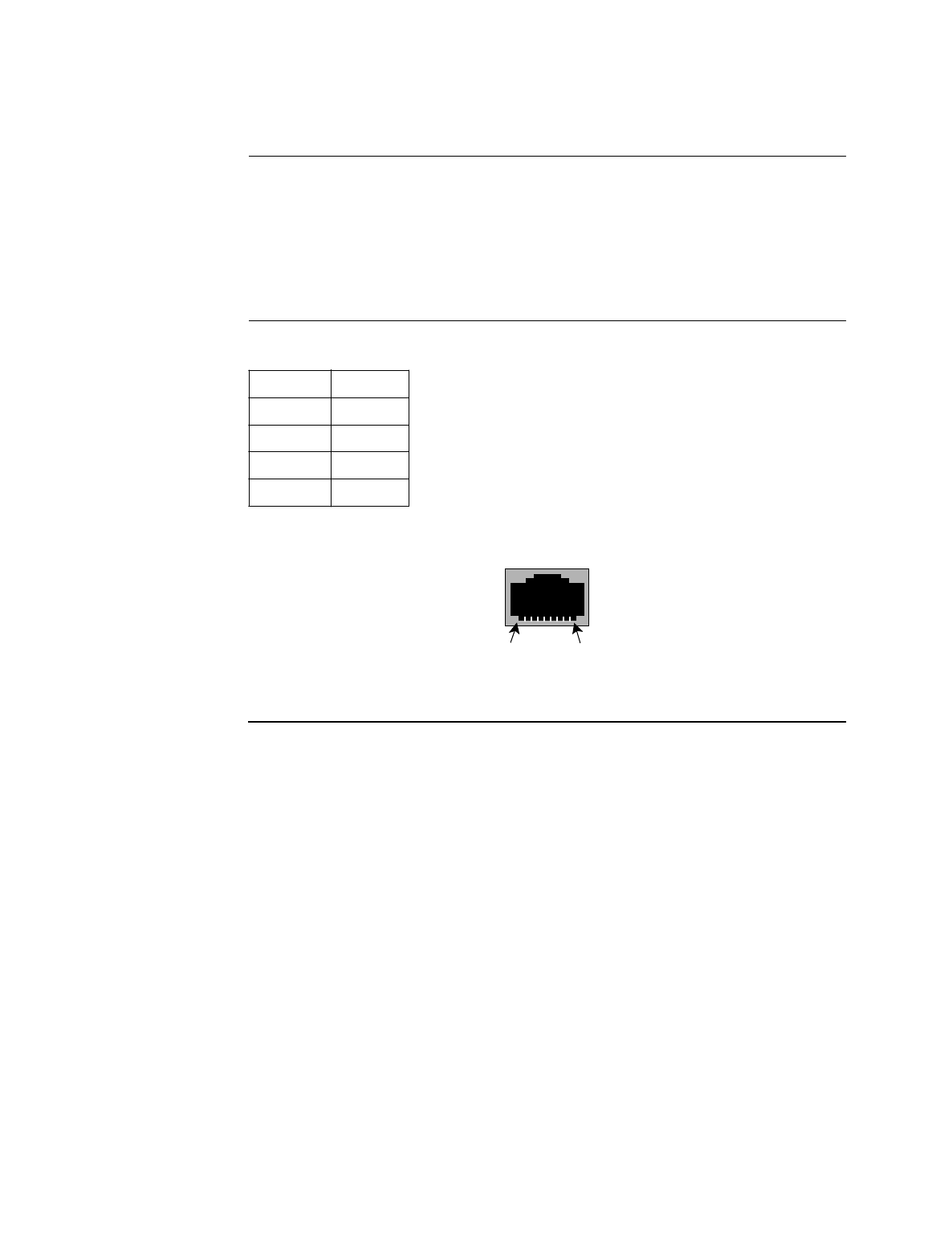
Connector Pinout Four of the pins are used, as shown below:
The connector pins are numbered indicated in the following diagram:
L
Figure B-1. RJ45 Pinout
Pin Pin
13
26
31
62
Pin 8 Pin 1

B-6 PathBuilder S21x Switch Cabling
RemoteVu Video Cables
RemoteVu Video Cables
Introduction The RemoteVu Daughtercard requires the following cables:
• RJ45-to-RJ45 Camera Interface Cable
• BNC-to-BNC Cable
RJ-45 Connector -
Camera Interface
Connector Pinout
This table describes the RJ-45 connector - camera interface connector:
Pin Function
1EIA-232 data input
2EIA-232 data output
3EIA-485/422 positive data output
4EIA-485/422 negative data output
5EIA-485/422 negative data input
6EIA-485/422 positive data input
7+12V (current available = 50 mA)
8Ground

PathBuilder S21x Switch Cabling B-7
DSU Daughtercard Cable
DSU Daughtercard Cable
DSU Daughtercard
Cable Pinout The following table shows the pinouts for the RJ48S connector:
Pin Signal Function
1 TX - TIP
2 TX - RING
3 RX - TIP
4 RX -RING

B-8 PathBuilder S21x Switch Cabling
V.35/V.36 Cable
V.35/V.36 Cable
V.35/V.36 DCE
Cable Pinout The following table shows the DCE pinouts forV.35 and V.36 cables.
Pin Function/Signal Name
1 SHIELD/FRAME GROUND
2 TRANSMITTED DATA A
3 RECEIVED DATA A
4 REQUEST TO SEND
5 CLEAR TO SEND
6 DATA SET READY
7 SIGNAL GROUND
8 DATA CARRIER DETECT
13 TRANSMIT CLOCK B
14 TRANSMITTED DATA B
15 TRANSMIT CLOCK A
16 RECEIVED DATA B
17 RECEIVE CLOCK A
18 RECEIVE CLOCK B
19 RECEIVE CLOCK B
20 DATA TERMINAL READY
21 TRANSMIT CLOCK B
22 EXTERNAL TRANSMIT CLOCK B
24 EXTERNAL TRANSMIT CLOCK A
25 (No Connection)

PathBuilder S21x Switch Cabling B-9
V.35/V.36 Cable
V.35/V.36 DTE
Cable Pinout The following table shows the DTE pinouts forV.35 and V.36 cables.
Pin Function/Signal Name
1 SHIELD/FRAME GROUND
2 TRANSMITTED DATA A
3 RECEIVED DATA A
4 REQUEST TO SEND
5 CLEAR TO SEND
6 DATA SET READY
7 SIGNAL GROUND
8 DATA CARRIER DETECT
13 TRANSMIT CLOCK B
14 TRANSMITTED DATA B
15 TRANSMIT CLOCK A
16 RECEIVED DATA B
17 RECEIVE CLOCK A
18 RECEIVE CLOCK B
19 RECEIVE CLOCK B
20 DATA TERMINAL READY
21 TRANSMIT CLOCK B
22 EXTERNAL TRANSMIT CLOCK B
24 EXTERNAL TRANSMIT CLOCK A
25 TEST MODE
(V.36 ONLY).

B-10 PathBuilder S21x Switch Cabling
V.11 Cable
V.11 Cable
V.11 DCE Cable The following table shows the DCE pinouts for the V.11 cable.
Pin V.11 Function/Signal Name
1 SHIELD/FRAME GROUND
2 T (A) TRANSMITTED DATA A
3 R (A) RECEIVED DATA A
4 C (A) CONTROL A
6 I (B) INDICATION B
7 SIGNAL GROUND
8 I (A) INDICATION A
13 S (B) TRANSMIT CLOCK B
14 T (B) TRANSMITTED DATA B
15 S (A) TRANSMIT CLOCK A
16 R (B) RECEIVED DATA B
17 * RECEIVE CLOCK A
18 * RECEIVE CLOCK B
19 * RECEIVE CLOCK B
20 C (B) CONTROL B
21 S(B) TRANSMIT CLOCK B
22 X (B) EXTERNAL TRANSMIT CLOCK B
24 X (A) EXTERNAL TRANSMIT CLOCK A
*These V.11 signals are not used in the X.21 standard.

PathBuilder S21x Switch Cabling B-11
V.11 Cable
V.11 DTE Cable The following table shows the DTE pinouts for the V.11 cable.
Pin Function/Signal Name
1 SHIELD/FRAME GROUND
2 TRANSMITTED DATA A
3 RECEIVED DATA A
4 CONTROL A
6 INDICATION B
7 SIGNAL GROUND
8 INDICATION A
13 TRANSMIT CLOCK B
14 TRANSMITTED DATA B
15 TRANSMIT CLOCK A
16 RECEIVED DATA B
17 RECEIVE CLOCK A
18 RECEIVE CLOCK B
19 RECEIVE CLOCK B
20 CONTROL B
21 TRANSMIT CLOCK B
22 EXTERNAL TRANSMIT CLOCK B
24 EXTERNAL TRANSMIT CLOCK A

B-12 PathBuilder S21x Switch Cabling
V.24 Cable
V.24 Cable
V.24 DCE Cable The following table shows the DCE pinouts for the V.24 cable. These pins are
assigned double functions in the V.24 cable:
• Pin 15: Outputs TRANSMIT CLOCK if the port is configured for internal
clocks. Otherwise it acts as a V.54 Loop 3 signal when connected to a modem.
• Pin 22: Used as the Ring Indicator output if the port is configured to emulate a
dial modem. For this to work properly, the RI/TM switch of the port must be
set to RI. When the RI/TM switch is set to TM, this pin acts as an input, and
the TM output from the attached modem (pin 25 on the modem) comes into
the 6500 on this pin.
Pin Function/Signal Name
1 Shield/Frame Ground
2 TXD
3RXD
4RTS
5CTS
6DSR
7 Signal Ground
8DCD
14 DATA RESTRAINT
15 TRANSMIT CLOCK or V.54 Loop 3 *
16 STANDBY INDICATOR
17 RECEIVE CLOCK
18 EXTERNAL RECEIVE CLOCK
20 DTR
21 V.54 Loop 2
22 RI/TM *
24 EXTERNAL TRANSMIT CLOCK
25 TEST MODE

PathBuilder S21x Switch Cabling B-13
V.24 Cable
V.24 DTE Cable The following table shows the DTE pinouts for the V.24 cable.
Pin Function/Signal Name
1 Shield/Frame Ground
2 TXD
3RXD
4RTS
5CTS
6DSR
7 Signal Ground
8DCD
14 DATA RESTRAINT
15 TRANSMIT CLOCK
16 STANDBY INDICATOR
17 RECEIVE CLOCK
18 EXTERNAL RECEIVE CLOCK or V.54 Loop 3 *
20 DTR
21 V.54 Loop 2
22 (No Connection)
24 EXTERNAL TRANSMIT CLOCK
25 MAKE BUSY

B-14 PathBuilder S21x Switch Cabling
V.24 Cable

Troubleshooting Your PathBuilder S21x Switch C-1
Appendix C
Troubleshooting Your PathBuilder S21x Switch
In This Appendix
Introduction This appendix describes some of the actions you can take to correct problems you
may be having with your PathBuilder S21x switch.
C-2 Troubleshooting Your PathBuilder S21x Switch
While Setting Up Your Configuration
While Setting Up Your Configuration
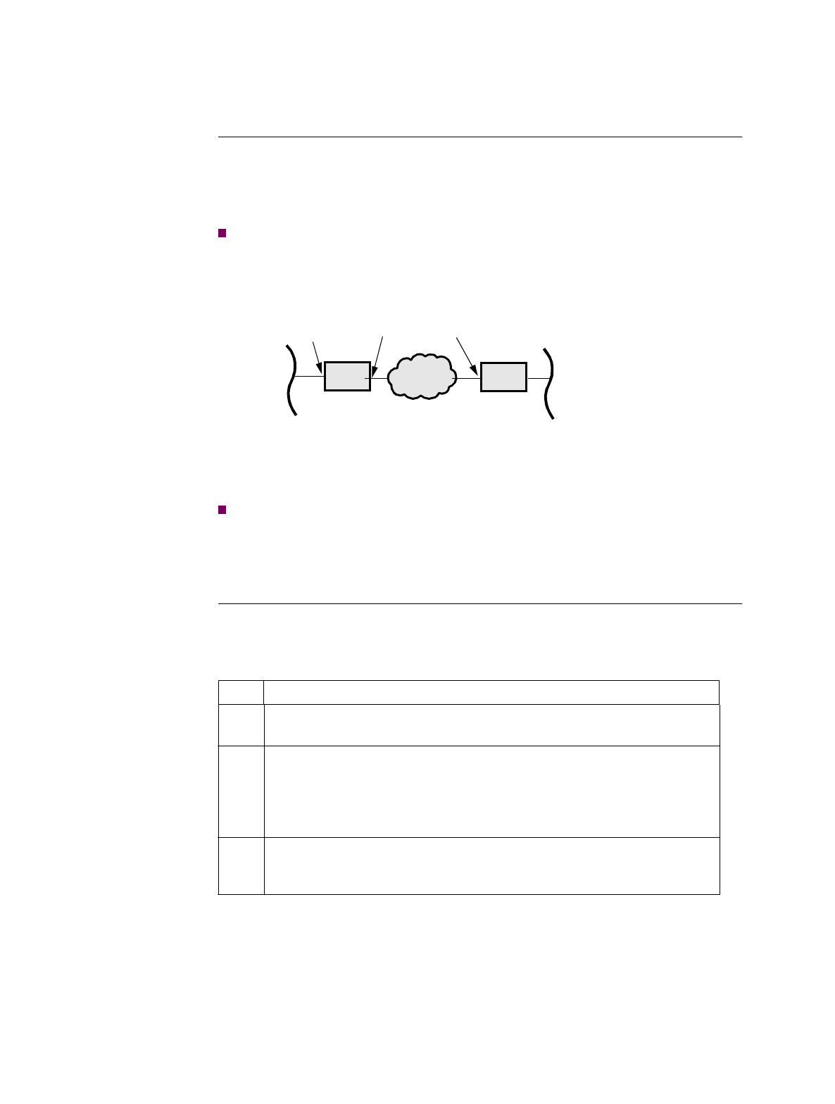
Introduction This section describes the ways you can use to isolate problems that you may
encounter while setting up a PathBuilder S21x switch to pass IP traffic over PPP
links. For discussion purposes, the following network configuration (shown in
Figure C-1) is assumed.
Note
The configuration of the local PathBuilder S21x switch and the number to call
can be obtained by defaulting the node—selecting “Default Node” from the
CTP’s Main menu.
Figure C-1. Network Configuration
Note
The IP addresses used in this configuration example are for illustration purposes
only. You must obtain registered IP addresses from your network administrator
or your Internet Service provider, and configure them in your PathBuilder S21x
switch before connecting to the Internet or Intranet.
Checking the
Physical
Connection
Use these procedures to check your PathBuilder S200 series switch connection and
interface:
Remote
Network
Local
PB S200 Network Remote
PB S200
Your Local
Network
(905) 555-6666 (905) 555-1234
10.10.10.1 10.10.20.1 10.10.20.2
10.10.30.0
10.10.10.0
Step Action
1Ensure that the STS LED is ON to confirm that power is connected and
that the unit is working. (Other LEDs may be ON or blink occasionally.)
2If the STS LED flashes continuously for more than 30 seconds after the
power is applied, the software image in the flash is corrupted and the
node is waiting for software to be coldloaded. Refer to the Software
Installation and Coldloading Manual for more infromation on cold-
loading software.
3If you are connected to the control port using an async terminal, (9600
bps, 8 bits, no parity), type “AT <CR>” and confirm that the Path-
Builder S200 series switch outputs “OK.” Then log into the CTP.

Troubleshooting Your PathBuilder S21x Switch C-3
While Setting Up Your Configuration
Pinging the Local
LAN Interface From the workstation or PC connected to the same local LAN segment that the
PathBuilder S21x switch is connected to, ping the LAN interface of the PathBuilder
S200 series switch (“ping 10.10.10.1”). The LAN LED should flash whenever a Ping
packet is received.
If the LAN LED does not flash, check the configuration of the PC and the LAN
connection and do the following:
If the LAN LED does flash, but there is no ping response, do the following:
Step Action
1Check the IP address and IP address mask of your PC or workstation,
making sure that they are set to valid address and mask appropriate for
your local subnetwork. (In the above example, the IP address of the PC
must be set between 10.10.10.2 and 10.10.10.254) and the address mask
must be set to 255.255.255.0).
2Check the statistics of the LAN port (port 5) of the local node, making
sure that the “Carrier” says “Present”. If the “Carrier” field displays
“Lost”, there is a problem with your LAN connection and you should do
the following:
• If you are using a BNC connection between your workstation/PC
and the PathBuilder S21x switch, make sure that you put in the 50
Ω termination resistors at both ends of the line.
• If you are connecting your LAN using the 10BaseT and a 10BaseT
Hub, check the display at the Hub to ensure that the connection
between PathBuilder S21x switch and the Hub is correct. (Most
Hubs have LEDs that stay ON when the carrier is detected).
• Change the RJ45 twisted pair cable between PathBuilder S200
series switch and your Hub as it may be damaged. A straight-
through 10BaseT cable is generally required between PathBuilder
S21x switch and a 10BaseT Hub.
If there is only a single PC or workstation connecting to the PathBuilder
S200 series switch, and you are not using a 10BaseT Hub, ensure that
you have used the RJ45 crossover cable, shipped with your PathBuilder
S21x switch, to connect between the PC and the PathBuilder S200
series switch.
Step Action
1From the CTP, check the statistics of the LAN port (Port 5) (select menu
option Statistics, and select port 5) while sending ping packets.
2Confirm that the Rx Frame Count, in the Data Summary, increases as
the ping packet arrives.
3Check the Tx Frame Count field in the Data Summary part of the LAN
port statistics. If the field increases for every ping packet it receives, the
LAN and the configuration should be working.

C-4 Troubleshooting Your PathBuilder S21x Switch
While Setting Up Your Configuration
Pinging the Local
WAN Interface Once you are successful in getting ping responses from the local LAN interface, you
can proceed to ping the local WAN interface (“ping 10.10.20.1” in the example). If
there is no response, then check the following:
4If the RX Frame count increases, but the Tx Frame Count does not, the
problem is most likely due to misconfiguration in the IP router Interface
#1. Make sure that the IP addresses and IP address mask (select menu
option Router -> IP Interfaces -> Interface 1) are set properly.
Step Action
Step Action
1Confirm that the IP interfaces (either 5 or 6) of the WAN link that you
are trying to ping are configured for Enable. (Select menu item
Router->Configure Interface States.)
2Confirm that the IP address and IP address mask of the WAN interface
you are pinging are configured properly.

Technical Support D-1
Appendix D
Technical Support
3Com provides easy access to technical support information through a variety of
services. This appendix describes these services.
Information contained in this appendix is correct at time of publication. For the very
latest, 3Com recommends that you access the 3Com Corporation World Wide Web
site.
Online Technical
Services 3Com offers worldwide product support 24 hours a day, 7 days a week, through the
following online systems:
• World Wide Web site
• 3Com FTP site
• 3Com Bulletin Board Service (3Com BBS)
•3ComFacts
SM automated fax service
World Wide Web
Site Access the latest networking information on the 3Com Corporation World Wide Web
site by entering the URL into your Internet browser:
http://www.3com.com/
This service provides access to online support information such as technical
documentation and software library, as well as support options ranging from
technical education to maintenance and professional services.
3Com FTP Site Download drivers, patches, and software, across the Internet from the 3Com public
FTP site. This service is available 24 hours a day, 7 days a week.
To connect to the 3Com FTP site, enter the following information into your FTP
client:
• Hostname: ftp.3com.com (or 192.156.136.12)
• Username: anonymous
• Password: <your Internet e-mail address>
Note
A user name and password are not needed with Web browser software such as
Netscape Navigator and Internet Explorer.

D-2 Technical Support
3Com Bulletin
Board Service The 3Com BBS contains patches, software, and drivers for 3Com products. This
service is available through analog modem or digital modem (ISDN) 24 hours a day,
7 days a week.
Access by Analog Modem
To reach the service by modem, set your modem to 8 data bits, no parity, and 1 stop
bit. Call the telephone number nearest you:
Access by Digital Modem
ISDN users can dial in to the 3Com BBS using a digital modem for fast access up to
56 Kbps. To access the 3Com BBS using ISDN, use the following number:
1 408 654 2703
3ComFacts
Automated Fax
Service
The 3ComFacts automated fax service provides technical articles, diagrams, and
troubleshooting instructions on 3Com products 24 hours a day, 7 days a week.
Call 3ComFacts using your Touch-Tone telephone:
1 408 727 7021
Support from Your
Network Supplier If additional assistance is required, contact your network supplier. Many suppliers
are authorized 3Com service partners who are qualified to provide a variety of
services, including network planning, installation, hardware maintenance,
application training, and support services.
When you contact your network supplier for assistance, have the following
information ready:
• Product model name, part number, and serial number
• A list of system hardware and software, including revision levels
• Diagnostic error messages
• Details about recent configuration changes, if applicable
Country Data Rate Telephone Number
Australia Up to 14,400 bps 61 2 9955 2073
Brazil Up to 14,400 bps 55 11 5181 9666
France Up to 14,400 bps 33 1 6986 6954
Germany Up to 28,800 bps 4989 62732 188
Hong Kong Up to 14,400 bps 852 2537 5601
Italy Up to 14,400 bps 39 2 27300680
Japan Up to 14,400 bps 81 3 3345 7266
Mexico Up to 28,800 bps 52 5 520 7835
P.R. of China Up to 14,400 bps 86 10 684 92351
Taiwan,
R.O.C. Up to 14,400 bps 886 2 377 5840
U.K. Up to 28,800 bps 44 1442 438278
U.S.A. Up to 28,800 bps 1 408 980 8204

Technical Support D-3
If you are unable to contact your network supplier, see the following section on how
to contact 3Com.
Support from
3Com If you are unable to obtain assistance from the 3Com online technical resources or
from your network supplier, 3Com offers technical telephone support services. To
find out more about your support options, please call the 3Com technical telephone
support phone number at the location nearest you.
When you contact 3Com for assistance, have the following information ready:
• Product model name, part number, and serial number
• A list of system hardware and software, including revision levels
• Diagnostic error messages
• Details about recent configuration changes, if applicable
Below is a list of worldwide technical telephone support numbers:
Country Telephone Number Country Telephone
Number
Asia Pacific Rim
Australia
Hong Kong
India
Indonesia
Japan
Malaysia
New Zealand
Pakistan
Philippines
1 800 678 515
800 933 486
61 2 9937 5085
001 800 61 009
0031 61 6439
1800 801 777
0800 446 398
61 2 9937 5085
1235 61 266 2602
P.R. of China
Singapore
S. Korea
From anywhere in S. Korea:
From Seoul:
Taiwan, R.O.C.
Thailand
10800 61 00137 or
021 6350 1590
800 6161 463
82 2 3455 6455
00798 611 2230
0080 611 261
001 800 611 2000
Europe
From anywhere in Europe,
call: +31 (0)30 6029900 phone
+31 (0)30 6029999 fax
From the following European countries, you may use the toll-free numbers:
Austria
Belgium
Denmark
Finland
France
Germany
Hungary
Ireland
Israel
Italy
06 607468
0800 71429
800 17309
0800 113153
0800 917959
0130 821502
00800 12813
1 800 553117
177 3103794
1678 79489
Netherlands
Norway
Poland
Portugal
South Africa
Spain
Sweden
Switzerland
U.K.
0800 0227788
800 11376
0800 3111206
05 05313416
0800 995014
900 983125
020 795482
0800 55 3072
0800 966197
Latin America
Argentina
Brazil 541 312 3266
55 11 523 2725, ext. 422 Colombia
Mexico 571 629 4847
01 800 849 2273
North America 1 800 NET 3Com
(1 800 638 3266)

D-4
Returning
Products for Repair Before you send a product directly to 3Com for repair, you must first obtain a Return
Materials Authorization (RMA) number. Products sent to 3Com without RMA
numbers will be returned to the sender unopened, at the sender’s expense.
To obtain an RMA number, call or fax:
3/26/98
Country Telephone Number Fax Number
Asia, Pacific Rim 65 543 6342 65 543 6348
Europe, South Africa, and
Middle East 011 44 1442 435860 011 44 1442 435718
From the following European countries, you may call the toll-free numbers; select
option 2 and then option 2:
Austria
Belgium
Denmark
Finland
France
Germany
Hungary
Ireland
Israel
Italy
Netherlands
Norway
Poland
Portugal
South Africa
Spain
Sweden
Switzerland
U.K.
06 607468
0800 71429
800 17309
0800 113153
0800 917959
0130 821502
00800 12813
1800553117
177 3103794
1678 79489
0800 0227788
800 11376
00800 3111206
05 05313416
0800 995014
900 983125
020 795482
0800 55 3072
0800 966197
Latin America 1 408 326 2927 1 408 764 6883
U.S.A. and Canada 1 800 876 3266, option 2 1 408 764 7120

Index
Index-1
Numerics
10Base2 Ethernet cable 2-9
10BaseT Ethernet cable 2-9
15637
ChapTitle
PathBuilder S21x Series Switch 2-1
3Com bulletin board service (3Com BBS) 2
3Com URL 1
3ComFacts 2
A
air circulation 2-3
Audience v
B
Battery
disposal 2-12
replacement schedule 2-12
replacement type 2-12
bulletin board service 2
C
Cable
10BaseT 2-9
cable
clearance 2-3
Cables 2-5
location 2-5
Cabling
10Base2 2-9
10BaseT 2-9
DECconnect pinout specifications B-2
caution, definition v
Configuration
troubleshooting during C-2
CTP
cable 2-9
description 1-2
CTP Port 1-2
D
Daughtercard
Dual Slots 1-2
Daughtercards 1-2
DSU 1-3
options 2-11
DSU daughtercard
overview 1-3
E
Electromagnetic specifications A-1
Environmental specifications A-1
F
fax service (3ComFacts) 2
Front Panel 3-3
I
Installing
PathBuilder S21x Switch 2-5
L
List of parts 2-2
M
Missing parts
what to do 2-2
Multiprotocol support 1-5
N
network supplier support 2
O
online technical services 1
Ordering information
PathBuilder S200 Series User Guides ix
Overview of contents vii
P
Parts list 2-2
PathBuilder S200 Series User Guides ix
PathBuilder S21x Switch
configuration 2-5
installing 2-5
Shipment Contents 2-2
Top Cover Removal 2-13
unpacking 2-5
Physical specifications A-2
power
source 2-3
Power requirements A-2
Powering on 3-2
Powerup
diagnostics 3-2, 3-3
FLASH memory corruption 3-4

Index-2
hardware failure 3-4
software failure 3-4
power-up 3-2
Diagnostics 3-3
R
returning products for repair 4
RFC 877
description 1-5
S
Safety specifications A-2
site preparation 2-3
Special notices
description v
Specifications
electromagnetic A-1
environmental A-1
physical A-2
power requirements A-2
safety A-2
T
technical support
3Com URL 1
bulletin board service 2
fax service 2
network suppliers 2
product repair 4
Troubleshooting C-1
configuration C-2
U
Unpacking
parts list 2-2
URL 1
V
Vanguard 320 1-1
overview 1-1
W
warning, definition v
World Wide Web (WWW) 1
