3Com WL311 Wireless Building-to-Building Bridge WL-311 User Manual TZ UG
3Com Corporation Wireless Building-to-Building Bridge WL-311 TZ UG
UserManual.wiki
>
3Com
>
WL311 User Manual
manual
Navigation menu
Upload a User Manual
Namespaces
Wiki Guide
HTML
PDF
Info
Views
User Manual
Discussion / Help
Navigation
![ContentsConfiguration and Management Features 42Local Configuration 42Remote Configuration Support 42Dimensions 43Environmental 43BUsing the Terminal ConfiguratorEstablishing a Direct Serial Connection 45Establishing a Telnet Connection 46Using the Terminal Configurator 47Main Menu Overview 47Edit Configuration Menu Overview 48Using The Editor 48Configuration File Format 48File Contents 49System 49[configure] 49[bridge] 49Bridged Ethernet (lan0) 49[hardware] 49[encryption] 50[rmp] 50[bootp] 50[ip] 51Error Codes 51IndexLimited Warranty and Regulatory Compliance Information3Com Corporation Limited WarrantyRegulatory Compliance Information](https://usermanual.wiki/3Com/WL311/User-Guide-157211-Page-5.png)

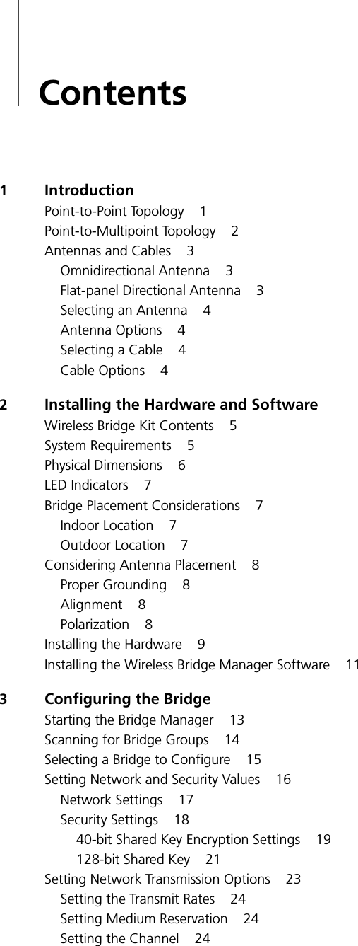
![5Troubleshooting Bridge Problems40Handling Event Log ErrorsThe following table lists event log errors. (See “Using the Log Viewer” on page 33 for more information about accessing the event log.) All entries in the event log are preceded by a number. This number is a time stamp used by Customer Support, but is not relevant to looking up items in this table.Handling Terminal Configurator Error CodesSee Appendix B, “Using the Terminal Configurator,” for detailed information about using the Terminal Configurator method to configure your 3Com Wireless Building-to-Building Bridge.Error Code DescriptionUART Error – No Rx Buffer AvailableData is being sent to the UART at a rate faster than it can clear its receive buffers, and data is being lost.Note that if you are using the serial port menu system for configuration, flow control will not be enabled in the wireless bridge. To avoid getting this error while in the serial port configuration system, simply type slower.Initialization of interface "lan0" failed.The bridge could not be initialized.Try each of the following steps in order. If any of these steps succeeds, there is no need to perform any of the later steps; otherwise continue to the next step.1Reset the wireless bridge.2Unplug the power, wait for approximately 30 seconds and then reapply power.3Reset the wireless bridge to the factory default configuration and reset the wireless bridge.4Contact 3Com Customer Support if the problem persists.Error Code DescriptionXxxx: [yyyy]: section does not existSection named yyyy in configuration file named xxxx was missing.Save your current configuration (if applicable). Reset the wireless bridge configuration to factory defaults. Reset the wireless bridge. Restore configuration (if applicable).Xxxx: [yyyy]: “zzzz”:entry refers to non-existent sectionEntry zzzz refers to a section that is not located in file xxxx.Save your current configuration (if applicable). Reset the wireless bridge configuration to factory defaults. Restore configuration (if applicable).Xxxx: [yyyy]: "zzzz":entry does not existEntry zzzz in section yyyy of file xxxx was missing.Save your current configuration (if applicable). Reset the wireless bridge configuration to factory defaults. Reset the wireless bridge. Restore configuration (if applicable).Xxxx: [yyyy]: "zzzz":entry is invalidEntry zzzz in section yyyy of file xxxx contains an invalid value.Check the entry in the configuration for zzzz. If you cannot find zzzz in the wireless bridge Bridge Manager program, you may have to use the serial port or Telnet configuration menus.Xxxx: <[yyyy]zzzz>:Unable to add route.Route values are out of range compared to the interface values.Set the route value to “automatic.” If “automatic” does not work for your wireless bridge, check the values you set for the route to make sure they correspond to your other IP parameters.Xxxx: file does not exist. Configuration file could not be found.Reset the configuration to factory defaults, and reset the wireless. If the problem persists, contact 3Com Customer Support.](https://usermanual.wiki/3Com/WL311/User-Guide-157211-Page-46.png)
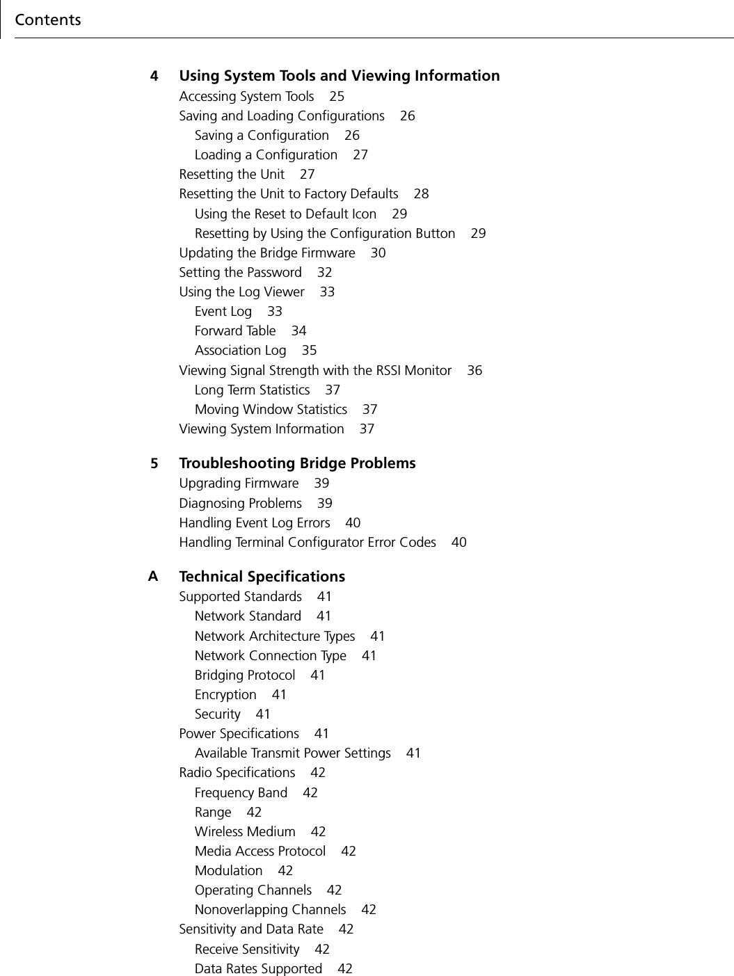
![BUsing the Terminal Configurator48Edit Configuration Menu OverviewThe Edit Configuration Menu contains three selections:■Return to Main MenuGoes back to the previous menu selections.■SystemDisplays the editor screen with the configuration file for system options.■Bridged Ethernet (lan0)Displays the editor screen with the configuration file for the radio parameters and IP network settings.Using The EditorSelecting one of the configuration files above will bring that file into the editor. Once inside the editor, you may use arrow keys to move the cursor around. If the arrow keys do not work with your terminal emulator, press Ctrl+P for up [previous], Ctrl+N for down [next], Ctrl+B for left [back], and Ctrl+F for right [forward] for cursor motion.For faster motion, press Ctrl+A to jump to the beginning of the line, and Ctrl+E to jump to the end. (Those familiar with the Emacs editor should feel comfortable with these keystrokes.)To make changes in the editor, simply move the cursor to the point you want to change and start typing. You can delete text behind the cursor by moving the cursor to the position immediately following the character you want to remove, and then by pressing either the Backspace or Delete keys, or by typing Ctrl+H. To delete text in front of the cursor, press Ctrl+D. To delete text from the cursor to the end of the line, press Ctrl+K.After editing is completed, save these changes by pressing Ctrl+W. After the changes are saved, the Edit Configuration menu will return to the screen. Although changes will be saved, they will not take effect until you power the wireless bridge off and back on. If you decide that you do not want to save the changes you have made, press Ctrl+X. The editor will ask you for confirmation, and then will return you to the Edit Configuration Menu.Screen corruptions or confusions may occur due to many terminal emulation software packages not emulating VT100 correctly. If the screen display becomes corrupted or confused as you type, press Ctrl+L to force a screen to redraw the image.Configuration File FormatThose familiar with the Windows WIN.INI file format will recognize the format of the configuration file. The file is divided into sections that define a particular grouping of options. Each section contains a section header at the top, shown as a string of text surrounded by square brackets: [ ]. This string is the section title. After each section header, there is a list of entries containing equal signs. The text before the equal sign is a key and the text after the equal sign is the value. Changing the value of different keys is how configuration changes are performed.Comments may be stored in the configuration file by inserting a pound sign (#) before the text to be added. This allows room for an explanation as to why certain settings have been made, who made the changes, etc. You may write anything in a comment, but the comment ends at the end of the line. You can create multi-line comments by inserting the # at the beginning of each line. For example:# This is a comment.# This is line #2 of the comment.this = no comment# But this is one.](https://usermanual.wiki/3Com/WL311/User-Guide-157211-Page-54.png)
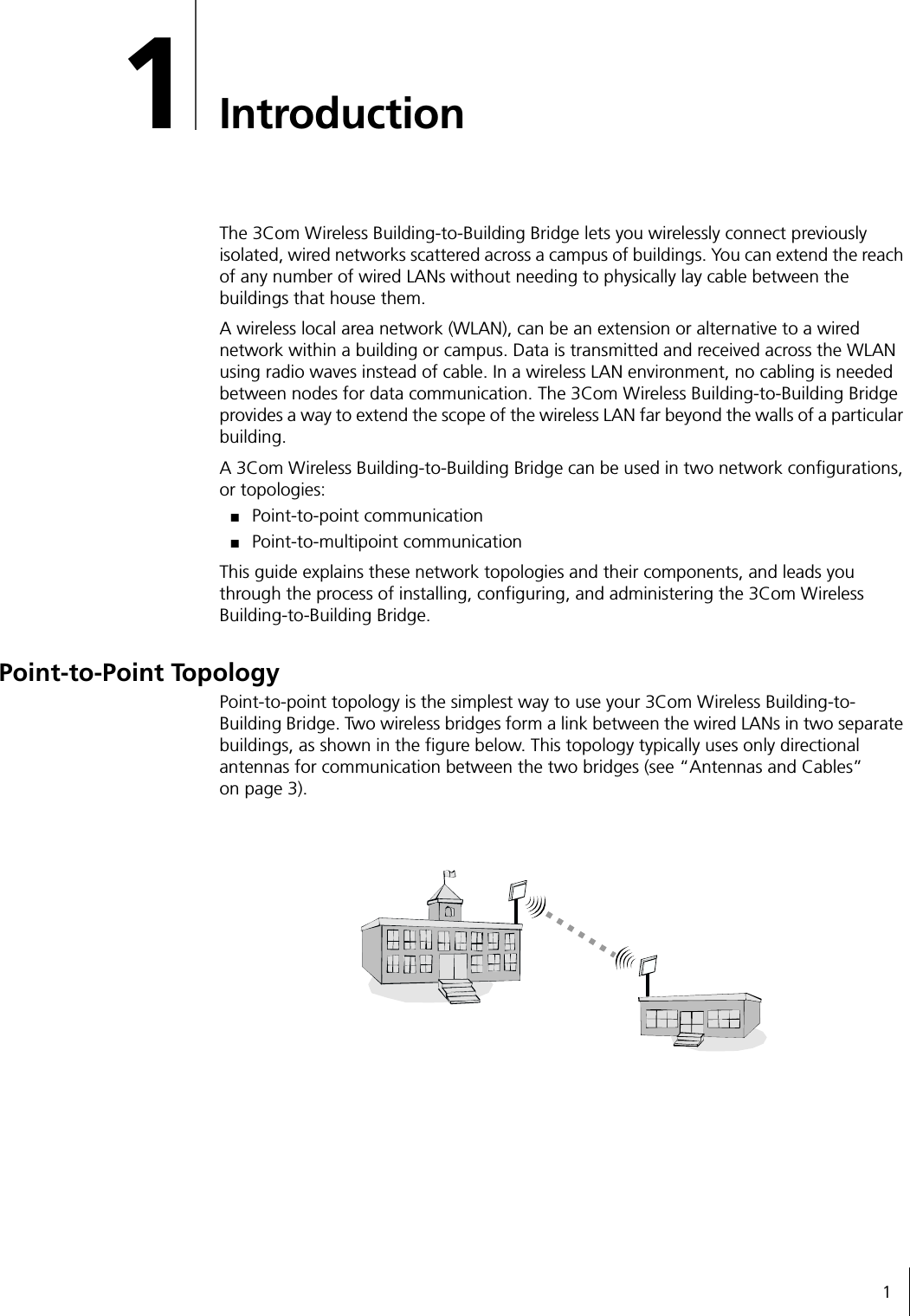
![File Contents49File ContentsSystem[configure]This section contains settings that pertain to the operation of the Configuration menus. Currently, there is only one: password.■password This setting allows the creation of a password that will be asked for upon entry to the Configuration screen. Up to 15 alphanumeric characters will be accepted. Do NOT use any characters other than numbers and letters in this password. Although the password is not hidden from the screen while editing, it will be hidden when entering configuration.[bridge]This section contains variables that are not specific to the radio.■AP refresh period This parameter has a default value of zero, which disables this function. Leave the AP refresh period at its default setting unless you are instructed to do otherwise by 3Com Technical Support.■encapsulation This parameter has a default value of on allowing bridging to occur. Leave the encapsulation set to its default value unless you are instructed to do otherwise by 3Com Technical Support.Bridged Ethernet (lan0)[hardware]This section contains settings for the actual wireless bridge radio hardware.■ESSID This parameter specifies the wireless network with which the wireless bridge will be connecting. Alphanumeric values may be used in this field. All wireless bridges must have the same ESSID to form a connection.■station name This parameter names an individual wireless bridge. The station name is used only for convenience of the network administrator and does not impact device operation. You may use any alphanumeric name.■mac address This parameter specifies Media Access Control, which is a unique alphanumeric address that defines each node of the network. This address should always be set to the default value of universal.■operating mode This parameter specifies the operating mode, which should always be set to the default value of ibss.■medium reservation This parameter controls the 802.11 RTS/CTS threshold. The default value is none, which disables medium reservation. Specify a packet length, in bytes, to enable RTS/CTS medium reservation for packets larger than the indicated size.■channel This parameter selects the channel setting for the radio. All wireless bridges in a single network should have the same channel setting.■mac timeout This parameter controls the low-level MAC timeout. Do not change this parameter from its default value of 324 unless instructed to do so by 3Com technical support.NOTE: Activating the refresh period does not impair the performance of the wireless bridge.](https://usermanual.wiki/3Com/WL311/User-Guide-157211-Page-55.png)
![BUsing the Terminal Configurator50■transmit rate This parameter controls the data rate at which the radio transmits. Legal values are: 1, 2, 5, and 11.■antenna diversity This parameter controls antenna diversity. The wireless bridge has only a single antenna, so this parameter should always be kept at its default value of no.■enable encryption This parameter indicates whether WEP encryption by the radio is desired or not. Setting of the various encryption options is done in the [encryption] section.[encryption]This section contains the configuration parameters that are used when encryption is enabled. If encryption is not enabled, these parameters have no effect on the wireless bridge operation.■transmit key This value sets which of the following keys are used to encrypt transmitted data. The default setting for this value is 1.■encryption key 1-4 This value is one of the keys to use for encrypting and decrypting data on the radio. The key should be specified as either a 10-digit or a26-digit hexadecimal number. Note that the number should always have a 0x before the hexadecimal digits. Use 10 digits for a 64-bit key, and 26 digits for a 128-bit key.[rmp]This section contains only a single low-level configuration parameter.■ethertype This value should be changed only if requested by 3Com Technical Support.[bootp]This section contains parameters to configure and enable bootp for the wireless bridge. You can configure the wireless bridge to determine its IP information from a bootp server. When enabled, the wireless bridge attempts to get its IP Address, Netmask, and Gateway information from the bootp server.■enable bootp This parameter should be set to Yes to enable bootp. Default value is No.■server ip address This parameter should be set to force the wireless bridge to get bootp information from a specific server. Using the default value causes the wireless bridge to broadcast the requests to all available servers.■server name This parameter has no impact on the operation of the wireless bridge bootp function, and is simply copied into the bootp messages. If your server requires a server name in bootp requests, then enter that name here.■server port This parameter specifies the port on which the bootp server is listening. It is unlikely that you should ever have to change this setting.■host port This parameter specifies the port from which the wireless bridge makes the bootp request. It is unlikely that you should ever have to change this setting.](https://usermanual.wiki/3Com/WL311/User-Guide-157211-Page-56.png)
![Error Codes51[ip]This section contains values for configuring the IP protocol. IP information is only necessary to “ping” the wireless bridge, or to “Telnet” to it. You are not required to set IP address information for normal operation of the wireless bridge, or to configure it using the Wireless Bridge Manager.■ip address This value specifies the IP address that will be used by other computers to communicate with a particular wireless bridge.■netmask When connected logically (AND) to the IP address, this value specifies the range of IP addresses within the local network.■broadcast In the local network, this value is the IP address used to refer to all computers simultaneously. The default automatic will work for almost all configurations. There should be no need to change this value.■route For the bridge, this value refer to section names that specify the routing options. The default of automatic will work for most configurations.■gateway If present, this value specifies the IP address of your Internet router or firewall. By default, this value is set to none. Change this value to the IP address of your gateway if you intend to connect to the wireless bridge from a computer outside your subnet.Error CodesError Code DescriptionXxxx: [yyyy]: section does not existSection named yyyy in configuration file named xxxx was missing.Save your current configuration (if applicable). Reset the wireless bridge configuration to factory defaults. Reset the wireless bridge. Restore configuration (if applicable).Xxxx: [yyyy]: “zzzz”:entry refers to non-existent sectionEntry zzzz refers to a section that is not located in file xxxx.Save your current configuration (if applicable). Reset the wireless bridge configuration to factory defaults. Restore configuration (if applicable).Xxxx: [yyyy]: "zzzz":entry does not existEntry zzzz in section yyyy of file xxxx was missing.Save your current configuration (if applicable). Reset the wireless bridge configuration to factory defaults. Reset the wireless bridge. Restore configuration (if applicable).Xxxx: [yyyy]: "zzzz":entry is invalidEntry zzzz in section yyyy of file xxxx contains an invalid value.Check the entry in the configuration for zzzz. If you cannot find zzzz in the wireless bridge Bridge Manager program, you may have to use the serial port or Telnet configuration menus.Xxxx: <[yyyy]zzzz>:Unable to add route.Route values are out of range compared to the interface values.Set the route value to automatic. If automatic does not work for your wireless bridge, check the values you set for the route to make sure they correspond to your other IP parameters.Xxxx: file does not exist. Configuration file could not be found.Reset the configuration to factory defaults, and reset the wireless. If the problem persists, contact 3Com Customer Support.](https://usermanual.wiki/3Com/WL311/User-Guide-157211-Page-57.png)