3Com WL311 Wireless Building-to-Building Bridge WL-311 User Manual TZ UG
3Com Corporation Wireless Building-to-Building Bridge WL-311 TZ UG
3Com >
manual

Wireless Building-to-Building Bridge
WL-311
Wireless Network Solution
User Guide
http://www.3com.com/
http://www.3com.com/productreg
Published June 2001
User guide version 1.0.0
3Com Corporation ■5400 Bayfront Plaza ■Santa Clara, California ■95052-8145 ■U.S.A.
Copyright © 2001 3Com Corporation. All rights reserved. 3Com is a registered trademark and the 3Com logo is a trademark of 3Com Corporation.
Assembled in the USA.
No part of this documentation may be reproduced in any form or by any means or used to make any derivative work (such as translation,
transformation, or adaptation) without written permission from 3Com Corporation.
3Com Corporation reserves the right to revise this documentation and to make changes in content from time to time without obligation on the part
of 3Com Corporation to provide notification of such revision or change.
3Com Corporation provides this documentation without warranty, term, or condition of any kind, either implied or expressed, including, but not
limited to, the implied warranties, terms or conditions of merchantability, satisfactory quality, and fitness for a particular purpose. 3Com may make
improvements or changes in the product(s) and/or the program(s) described in this documentation at any time.
If there is any software on removable media described in this documentation, it is furnished under a license agreement included with the product as
a separate document, in the hard copy documentation, or on the removable media in a directory file named LICENSE.TXT or !LICENSE.TXT. If you are
unable to locate a copy, please contact 3Com and a copy will be provided to you.
UNITED STATES GOVERNMENT LEGEND
If you are a United States government agency, then this documentation and the software described herein are provided to you subject to the following:
All technical data and computer software are commercial in nature and developed solely at private expense. Software is delivered as “Commercial
Computer Software” as defined in DFARS 252.227-7014 (June 1995) or as a “commercial item” as defined in FAR 2.101(a) and as such is provided
with only such rights as are provided in 3Com’s standard commercial license for the Software. Technical data is provided with limited rights only as
provided in DFAR 252.227-7015 (Nov 1995) or FAR 52.227-14 (June 1987), whichever is applicable. You agree not to remove or deface any portion
of any legend provided on any licensed program or documentation contained in, or delivered to you in conjunction with, this User Guide.
Unless otherwise indicated, 3Com registered trademarks are registered in the United States and may or may not be registered in other countries.
3Com is a registered trademark and the 3Com logo is a trademark of 3Com Corporation.
Microsoft, Windows, and Windows NT are registered trademarks of Microsoft Corporation. Wi-Fi is a trademark of the Wireless Ethernet
Compatibility Alliance.
All other company and product names may be trademarks of the respective companies with which they are associated.

Contents
1Introduction
Point-to-Point Topology 1
Point-to-Multipoint Topology 2
Antennas and Cables 3
Omnidirectional Antenna 3
Flat-panel Directional Antenna 3
Selecting an Antenna 4
Antenna Options 4
Selecting a Cable 4
Cable Options 4
2Installing the Hardware and Software
Wireless Bridge Kit Contents 5
System Requirements 5
Physical Dimensions 6
LED Indicators 7
Bridge Placement Considerations 7
Indoor Location 7
Outdoor Location 7
Considering Antenna Placement 8
Proper Grounding 8
Alignment 8
Polarization 8
Installing the Hardware 9
Installing the Wireless Bridge Manager Software 11
3Configuring the Bridge
Starting the Bridge Manager 13
Scanning for Bridge Groups 14
Selecting a Bridge to Configure 15
Setting Network and Security Values 16
Network Settings 17
Security Settings 18
40-bit Shared Key Encryption Settings 19
128-bit Shared Key 21
Setting Network Transmission Options 23
Setting the Transmit Rates 24
Setting Medium Reservation 24
Setting the Channel 24

Contents
4Using System Tools and Viewing Information
Accessing System Tools 25
Saving and Loading Configurations 26
Saving a Configuration 26
Loading a Configuration 27
Resetting the Unit 27
Resetting the Unit to Factory Defaults 28
Using the Reset to Default Icon 29
Resetting by Using the Configuration Button 29
Updating the Bridge Firmware 30
Setting the Password 32
Using the Log Viewer 33
Event Log 33
Forward Table 34
Association Log 35
Viewing Signal Strength with the RSSI Monitor 36
Long Term Statistics 37
Moving Window Statistics 37
Viewing System Information 37
5Troubleshooting Bridge Problems
Upgrading Firmware 39
Diagnosing Problems 39
Handling Event Log Errors 40
Handling Terminal Configurator Error Codes 40
ATechnical Specifications
Supported Standards 41
Network Standard 41
Network Architecture Types 41
Network Connection Type 41
Bridging Protocol 41
Encryption 41
Security 41
Power Specifications 41
Available Transmit Power Settings 41
Radio Specifications 42
Frequency Band 42
Range 42
Wireless Medium 42
Media Access Protocol 42
Modulation 42
Operating Channels 42
Nonoverlapping Channels 42
Sensitivity and Data Rate 42
Receive Sensitivity 42
Data Rates Supported 42

Contents
Configuration and Management Features 42
Local Configuration 42
Remote Configuration Support 42
Dimensions 43
Environmental 43
BUsing the Terminal Configurator
Establishing a Direct Serial Connection 45
Establishing a Telnet Connection 46
Using the Terminal Configurator 47
Main Menu Overview 47
Edit Configuration Menu Overview 48
Using The Editor 48
Configuration File Format 48
File Contents 49
System 49
[configure] 49
[bridge] 49
Bridged Ethernet (lan0) 49
[hardware] 49
[encryption] 50
[rmp] 50
[bootp] 50
[ip] 51
Error Codes 51
Index
Limited Warranty and Regulatory Compliance Information
3Com Corporation Limited Warranty
Regulatory Compliance Information
1
1Introduction
The 3Com Wireless Building-to-Building Bridge lets you wirelessly connect previously
isolated, wired networks scattered across a campus of buildings. You can extend the reach
of any number of wired LANs without needing to physically lay cable between the
buildings that house them.
A wireless local area network (WLAN), can be an extension or alternative to a wired
network within a building or campus. Data is transmitted and received across the WLAN
using radio waves instead of cable. In a wireless LAN environment, no cabling is needed
between nodes for data communication. The 3Com Wireless Building-to-Building Bridge
provides a way to extend the scope of the wireless LAN far beyond the walls of a particular
building.
A 3Com Wireless Building-to-Building Bridge can be used in two network configurations,
or topologies:
■Point-to-point communication
■Point-to-multipoint communication
This guide explains these network topologies and their components, and leads you
through the process of installing, configuring, and administering the 3Com Wireless
Building-to-Building Bridge.
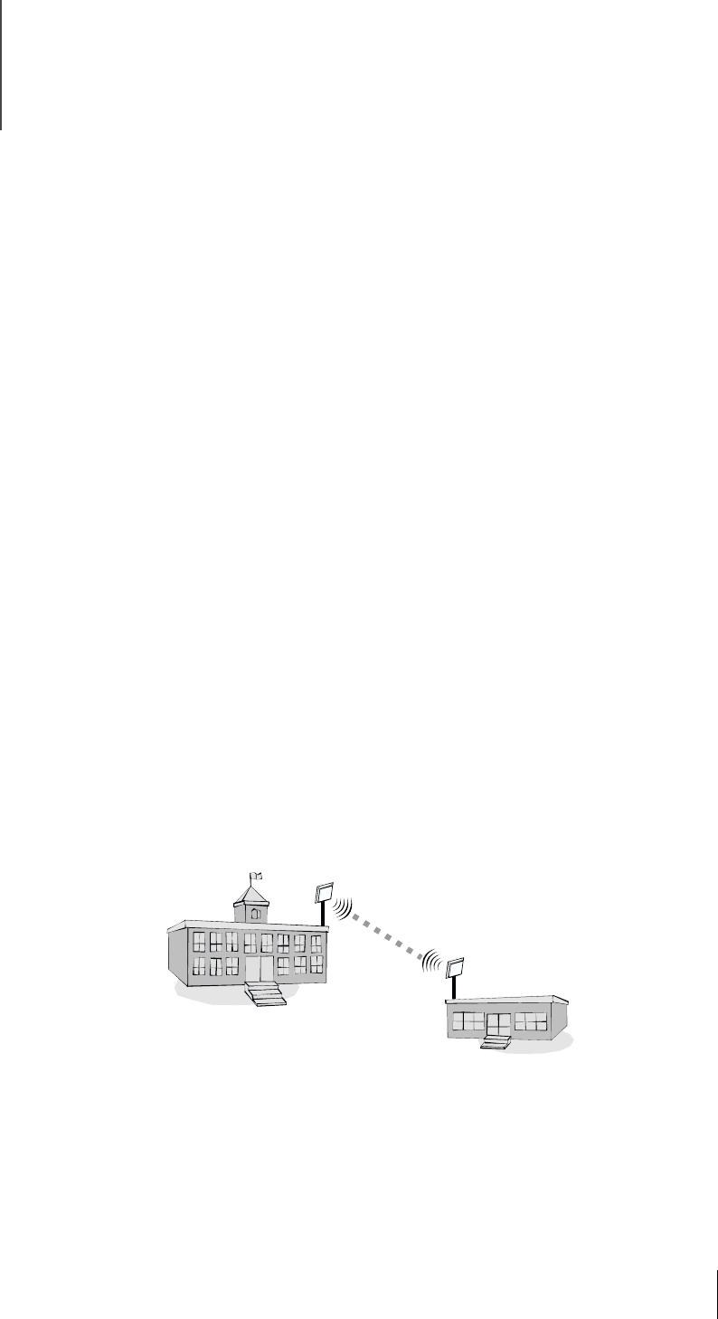
Point-to-Point Topology
Point-to-point topology is the simplest way to use your 3Com Wireless Building-to-
Building Bridge. Two wireless bridges form a link between the wired LANs in two separate
buildings, as shown in the figure below. This topology typically uses only directional
antennas for communication between the two bridges (see “Antennas and Cables”
on page 3).
1Introduction
2
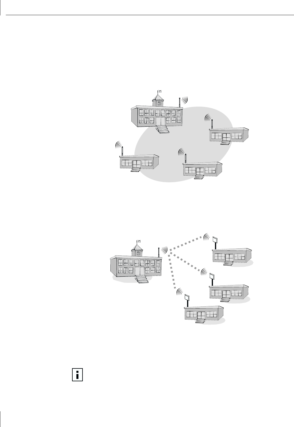
Point-to-Multipoint Topology
3Com Wireless Building-to-Building Bridges can be used for communicating among
multiple (two or more) bridges, with each bridge connected to a particular building’s wired
LAN. The next figure shows a bridging network in which four 3Com Building-to-Building
Bridges are used to provide wireless connectivity among four buildings. This topology
typically uses omnidirectional antennas for communication between bridges if bridging is
desired among all buildings in the bridging network without restriction (see “Antennas
and Cables” on page 3).
In this configuration, the wireless bridges make all four wired LANs appear to be
connected by the same Ethernet cable. Using wireless bridges in this manner provides a
cost-effective way to wirelessly link multiple wired LAN networks by eliminating the need
to install cables between buildings.
An alternative point-to-multipoint configuration is shown in the following figure.
In this example, the first building’s bridge is using an omnidirectional antenna while the
other three buildings have bridges using directional antennas. In this case, the three
bridges with directional antennas can communicate only with the bridge using the omni-
direction antenna; they cannot communicate directly with each other. The bridge using
the omnidirectional antenna can communicate with the other three bridges.
CAUTION: This alternative, mixed-antenna point-to-multipoint topology, can
possibly result in lower performance than a point-to-multipoint configuration that
uses only omnidirectional antennas.
Antennas and Cables
3
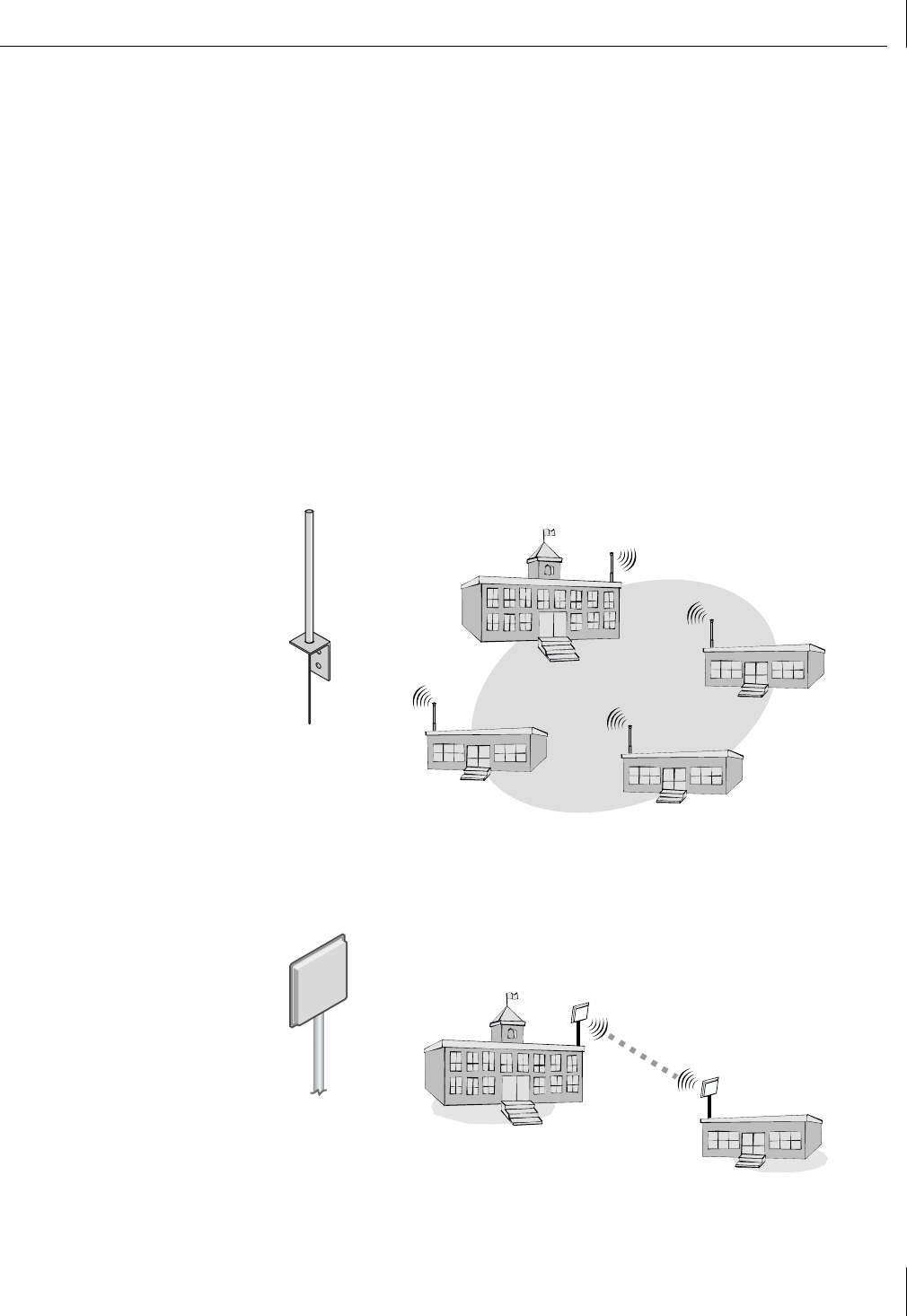
Antennas and Cables
You can connect the following types of antennas to the 3Com Wireless Building-to-
Building Bridge:
■Flat-panel directional
■Omnidirectional
For best performance, place each antenna outdoors using the mounting hardware
provided with the antenna. Outdoor placement is especially important if the building
consists of metal construction or has metal siding. If necessary, you can mount an antenna
inside a building; however, indoor placement reduces the antenna’s effective range.
The following figures illustrate the different types of antennas and typical examples of use.
See Chapter 2, “Installing the Hardware and Software,” for detailed information about
recommended 3Com antennas.
Omnidirectional Antenna
An omnidirectional antenna provides short-range, point-to-multipoint connectivity for two
or more wireless bridges. Range with an omnidirectional antenna is approximately 1300
meters at 11 megabits per second (Mbps).
Flat-panel Directional Antenna
A flat-panel directional antenna provides long-range, point-to-point connectivity between
two wireless bridges. Range can be as high as 4.1 kilometers (km) at 11 Mbps.

1Introduction
4
Selecting an Antenna
The following table shows guidelines for selecting antennas based upon their gain
properties (expressed in decibels (dB)). The gain of any antenna is essentially a
specification that quantifies how well that antenna is able to direct the radiated radio
frequency (RF) energy into a particular direction. Thus, high-gain antennas direct their
energy more narrowly and precisely, and low-gain ones direct energy more broadly.
The range estimates listed are those that can be expected between two 3Com Wireless
Building-to-Building Bridges using the listed antenna combinations.
9
Antenna Options
The following 3Com antennas are available for use with the 3Com Wireless Building-to-
Building Bridge:
■3CWE490 4 dB Omnidirectional
■3CWE491 8 dB Omnidirectional
■3CWE495 13 dB Bidirectional Panel
■3CWE496 18 dB Directional Panel
Selecting a Cable
Specific cables are available from 3Com for connecting the wireless bridge to an antenna.
In planning your bridging topology, it is important to account for signal attenuation due
to the cable and connectors used between the bridge and the antenna. Using the shortest
cables possible reduces signal loss.
3Com recommends using 50-ft cable with 18 dB antenna (with 10 dB attenuation) for
typical installations.
Cable Options
The following 3Com cables are available for use with the 3Com Wireless Building-to-
Building Bridge:
■3CWE480A — 6 ft
■3CWE481A — 20 ft
■3CWE482A — 50 ft
Gaina
Antenna A
a.Gain is shown in dB
Gain
Antenna B
Distance
(Meters)
Distance
(Miles) Antenna Types
4 4 522 0.3 Omni-to-omni
4 8 827 0.5 Omni-to-omni
8 8 1,311 0.8 Omni-to-omni
4 13 1,471 0.9 Omni-to-panel
4 18 2,616 1.6 Omni-to-panel
8 13 2,332 1.4 Omni-to-panel
8 18 4,146 2.6 Omni-to-panel
13 13 4,146 2.6 Panel-to-panel
13 18 3,695 2.3 Panel-to-panel
18b
b.18 dB antenna typically paired with 50-ft cable accessory
18 3,293 2.0 Panel-to-panel

5
2Installing the
Hardware and Software
This chapter describes the contents of the 3Com Wireless Building-to-Building Bridge
package, system requirements, configuration guidelines, and hardware and software
installation procedures.
Wireless Bridge Kit Contents
In your 3Com Wireless Building-to-Building Bridge package, you will find the following
components:
■3Com Wireless Building-to-Building Bridge
■RJ-45 Ethernet crossover cable
■5.2V Universal AC-to-DC power supply and cord
■Mounting hardware
■Printed quick start guide with warranty
■Installation CD containing this user guide and configuration software
If any of these items is missing or damaged, please contact the place of purchase or 3Com
Customer Support (http://support.3com.com).
System Requirements
Before you can install a set of wireless bridges, your system environment must satisfy the
conditions listed below. You need to have:
■Physically isolated Ethernet LANs
■Two or more 3Com Wireless Building-to-Building Bridges
■One antenna with cable for each wireless bridge unit (can be purchased separately
from 3Com as an accessory)
■Computer with Windows 95, 98, Me, Windows 2000, or Windows NT installed
CAUTION: Installing the 3Com Wireless Building-to-Building Bridge, cables, and
antennas should be done only by professional network personnel.
2Installing the Hardware and Software
6
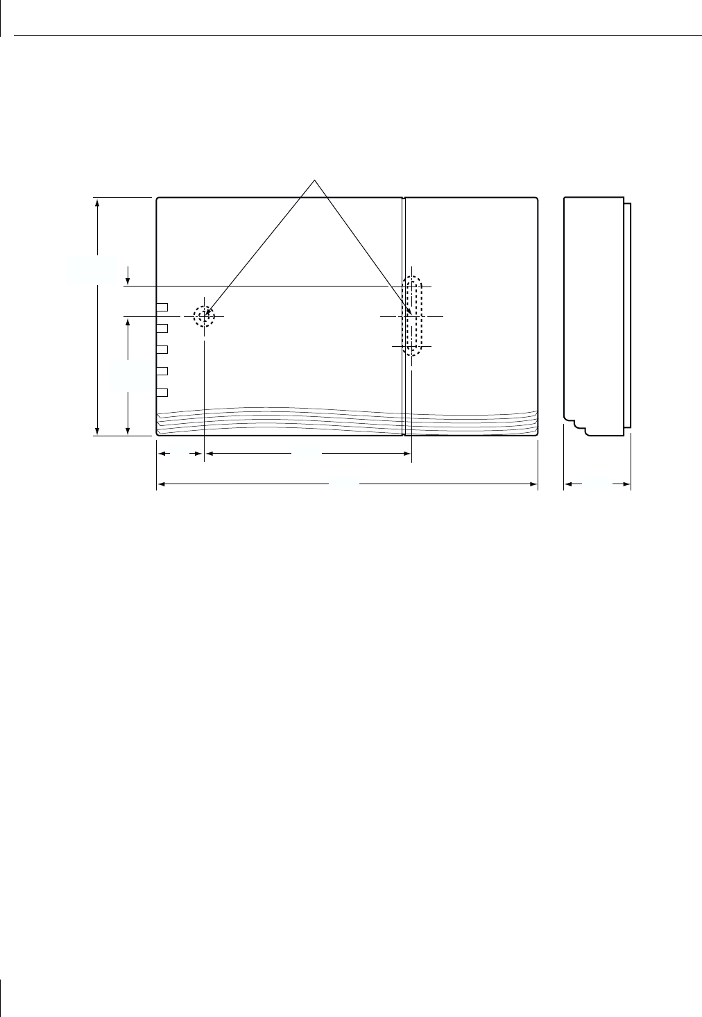
Physical Dimensions
If you want to mount the wireless bridge on a vertical surface, see the outside dimensions
and mounting hole dimensions of the mounting plate shown below. Primary dimensions
are given in inches and secondary dimensions are shown in millimeters.
3.38"
(86 mm)
.50"
(13 mm)
6.20"
(157 mm)
.77"
(20 mm)
1.10"
(28 mm)
1.95"
(49 mm)
3.89"
(99 mm)
Use #6 or M4 flathead fasteners
for mounting bracket
LED Indicators
7
LED Indicators
The 3Com Wireless Building-to-Building Bridge has five LED indicators, as shown in the
figure below.
The LED indicators are described in the table below:
Bridge Placement Considerations
Indoor Location
Place the wireless bridge in a location that:
■Is conveniently located for connection to the Ethernet network.
■Allows easy viewing of the front panel LED indicators, and access to the rear panel
connectors, if necessary.
Outdoor Location
It may be necessary to mount the wireless bridge in an outdoor location. If you place the
bridge in an outdoor location, you should cover it with an optional outdoor enclosure
accessory. To obtain an outdoor enclosure accessory, contact 3Com at http://www.3com.com.
For installation instructions, refer to the procedure provided with the enclosure accessory.
LED Lights
Power Green when power is applied.
Alert Amber when status information is available. View the event log for status information.
(See “Event Log” on page 33 for more information.)
Wireless Green when the bridge is associated with another bridge and lights amber during radio
communication.
Ethernet Green to show that a valid Ethernet link is present through the 10BASE-T port. Lights
amber during Ethernet activity.
Serial Green when receiving data through the serial port and lights amber when transmitting
data through the serial port.
Wireless
Building-to-Building
Bridge
Power
Alert
Wireless
Ethernet
Serial

2Installing the Hardware and Software
8
Considering Antenna Placement
You can place the antenna either indoors or outdoors. An outdoor location, such as a
rooftop, provides the following advantages:
■Fewer obstacles to signal paths between wireless bridges
■Increased antenna range
■Fewer multipath problems
Proper Grounding
To ensure the physical safety of anyone near the antenna and to prevent damage to
the wireless bridge, follow the building codes for antenna installations in your area.
This approach typically means making certain that antennas and antenna masts are
appropriately grounded to prevent injury or damage from lightning strikes.
Most of the antennas shipped with the wireless bridge do not have an electrical connection
between the mask mount and the coaxial cable shield. However, adding a lightning arrestor
will correct that situation by grounding the outer shield as recommended. In some arrestor
designs, there is also some over-voltage protection for the signal sent down the cable. If you
use such a component, be sure that it is designed to pass signals used in the 2.5 GHz signal
range (many inexpensive units are available with F connectors, but these are typically
designed for cable TV-UHF applications and may degrade the signals in the band used by
the wireless bridge).
Alignment
Position each antenna so that there are minimal obstacles between it and any other
antenna with which it will communicate. While maintaining a direct line of sight between
antennas is not strictly necessary, such an arrangement helps to ensure a strong signal.
Align each directional antenna to point at the antenna with which it will communicate.
If you place two directional antennas at different heights, tilt them up or down toward
each other for optimal signal strength. Make sure that the angle of tilt is identical for each
antenna: the antenna faces should be parallel.
While aligning the antenna, you may want to use the Wireless Bridge Manager Received
Signal Strength Indicator (RSSI) Monitor tool (preferably loaded on a mobile PC that can
be used at the antenna site) to adjust the antenna to achieve the maximum possible
received signal strength. See “Viewing Signal Strength with the RSSI Monitor” on page 36
for more information.
Polarization
Polarization is a physical phenomenon of radio signal propagation. In general, any two
antennas that are to form a link with each other must be set for the same polarization.
If for example, two antennas for a link are linearly polarized, they must both be vertically
polarized or horizontally polarized. If both antennas do not have the same polarization,
the link will either work poorly, or not at all.The situation where one antenna is vertically
polarized and the other is horizontally polarized is known as cross-polarization.
Antenna polarity should be identical for each antenna in a bridging link or network.
Vertical polarization is preferred in most cases. Make sure that every directional antenna is
properly oriented for vertical polarization (according to the polarization indicator shown
on the antenna panel).
Omnidirectional antennas should be vertically aligned in relation to the ground.
Installing the Hardware
9
Installing the Hardware
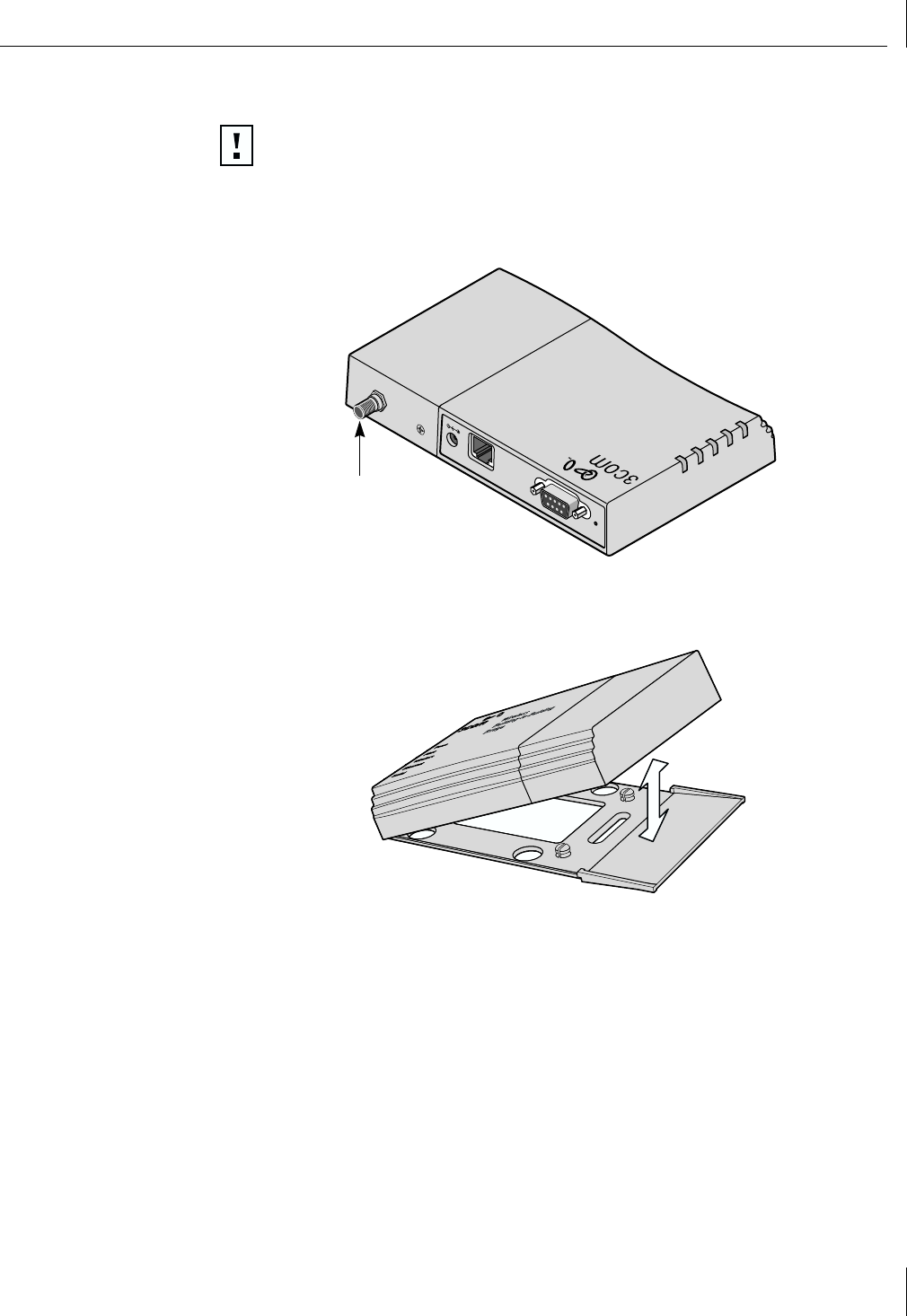
1Remove your 3Com Wireless Building-to-Building Bridge from the packaging.
The bridge ships fully assembled. An SMA port for attaching the antenna cable is
located on one side of the bridge (see figure below).
2If you plan to mount the bridge on the wall or ceiling, remove the bottom mounting
plate, as shown in the figure below. If you are not mounting the bridge, leave the
mounting plate on the bottom of the bridge.
3To mount the bridge, install the mounting plate where desired using the mounting
hardware provided (see “Physical Dimensions” on page 6 for the physical dimensions
of the mounting plate).
CAUTION: Installing the 3Com Wireless Building-to-Building Bridge, cables, and
antennas should be done only by professional network personnel.
Wireless
Building-to-Building
Bridge
Power
Alert
Wireless
Ethernet
Serial
5 VDC
10
Config.
Serial
RJ-45
SMA port
2Installing the Hardware and Software
10
4After securing the mounting plate to the desired location, attach the bridge onto the
mounting plate.
5If you are mounting the bridge in an outdoor location, install the outdoor enclosure
accessory according to the installation instructions provided with the accessory.
6Connect the antenna cable to the SMA port at the end of the bridge unit
(see figure below).
7Connect the other end of the antenna cable to the antenna.
8Insert one end of the RJ-45 crossover cable into the bridge 10BASE-T connector. Insert
the other end of the cable into your Ethernet LAN connector.
9Connect power to the bridge.
aConnect the six-pin DC power cable to the power adapter.
bConnect the round power plug of the DC cable to the port labeled 5 VDC.
cConnect the AC power cord to the other side of the power adapter.
dInsert the AC power cord into an AC power outlet.
10 Verify that the bridge Ethernet LED is illuminated (see “LED Indicators” on page 7),
indicating a valid Ethernet connection to your Ethernet LAN.
Your bridge hardware is now ready for configuration using the 3Com Wireless Building-
to-Building Bridge Manager software.
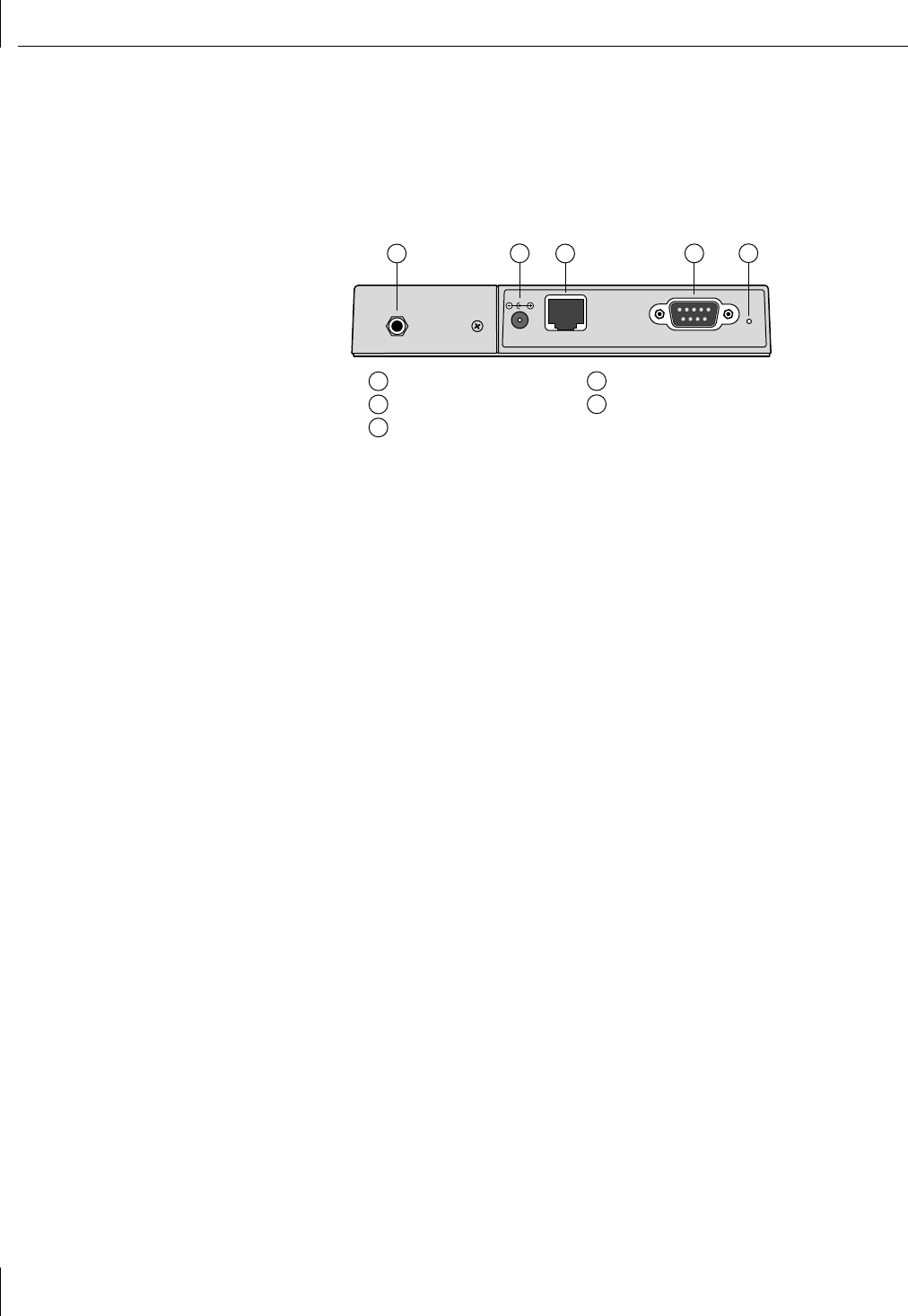
5 VDC RJ-45 Serial Config.
10
1 SMA port
2 Power jack
3 10BASE-T Ethernet port
4 Serial port
5 Configuration button
12345

Installing the Wireless Bridge Manager Software
11
Installing the Wireless Bridge Manager Software
You can install the 3Com Wireless Building-to-Building Bridge Manager on a PC or
workstation running Windows 95, 98, Me, Windows 2000, or Windows NT. The Bridge
Manager is a software configuration utility that allows you to graphically and remotely:
■Display a list of wireless bridges running on the local network.
■Display and edit the current configuration of any wireless bridge.
■Save and load configurations.
■Update the wireless bridge firmware.
■Perform all configuration and management functions.
You typically install the Bridge Manager on:
■One desktop computer, through which you can globally configure and administer all
of the wireless bridges.
■One laptop computer, through which you can adjust antenna polarization during
installation by using the RSSI monitor at the antenna site.
If the Bridge Manager is not available, you can use the terminal configurator as an
alternative method to configure the bridge. See Appendix B, “Using the Terminal
Configurator,” for more information.
1Insert the Installation CD into your computer’s CD-ROM drive.
If the installation program does not begin automatically:
aClick My Computer.
bClick the icon for the drive in which the Installation CD is located.
cDouble-click setup.exe.
The Welcome screen appears.
2Click Next to continue the installation.
The Software License screen appears.
3Click Yes to indicate that you agree with the displayed terms.
The Choose Destination Location screen appears. This screen displays the default path
and location for the Bridge Manager files and documents:
c:\program files\3com\3com wireless bridge manager
You can leave the directory set at the default path, or you can change the directory to
suit your requirements.
4Enter the directory in which the Bridge Manager program will be installed. When you
have finished, click Next to continue.
The Bridge Manager files and documents are installed in the directory you specified.
It is possible that the installer will require that you restart your computer to complete
the installation. When the installation is complete, a message is displayed that
confirms a successful installation.
5Click Finish to exit the installation.
The Bridge Manager is now installed and you are ready to use it to configure your
wireless bridges. Proceed to Chapter 3, “Configuring the Bridge.”
NOTE: When you first insert the Installation CD or run the Setup utility you will see
a message indicating that files are being copied to your system. These are
temporary files used by the installation program, and are not the Wireless Bridge
Manager program files.

13
3Configuring the Bridge
This chapter describes how to add a 3Com Wireless Building-to-Building Bridge to your
wireless network using the Wireless Bridge Manager configuration utility.
The 3Com Wireless Building-to-Building Bridge Manager software communicates with
each wireless bridge using a non-routable protocol. Therefore, your wireless bridges must
be accessible on the local subnet to communicate with the Bridge Manager.
Starting the Bridge Manager
To run the Wireless Bridge Manager, follow these steps:
1On the Windows taskbar, click Start.
2Select Programs and then select the Program Group you created when you installed
the Wireless Bridge Manager (see “Installing the Wireless Bridge Manager Software”
on page 11).
3Select the 3Com Wireless Bridge Manager entry.
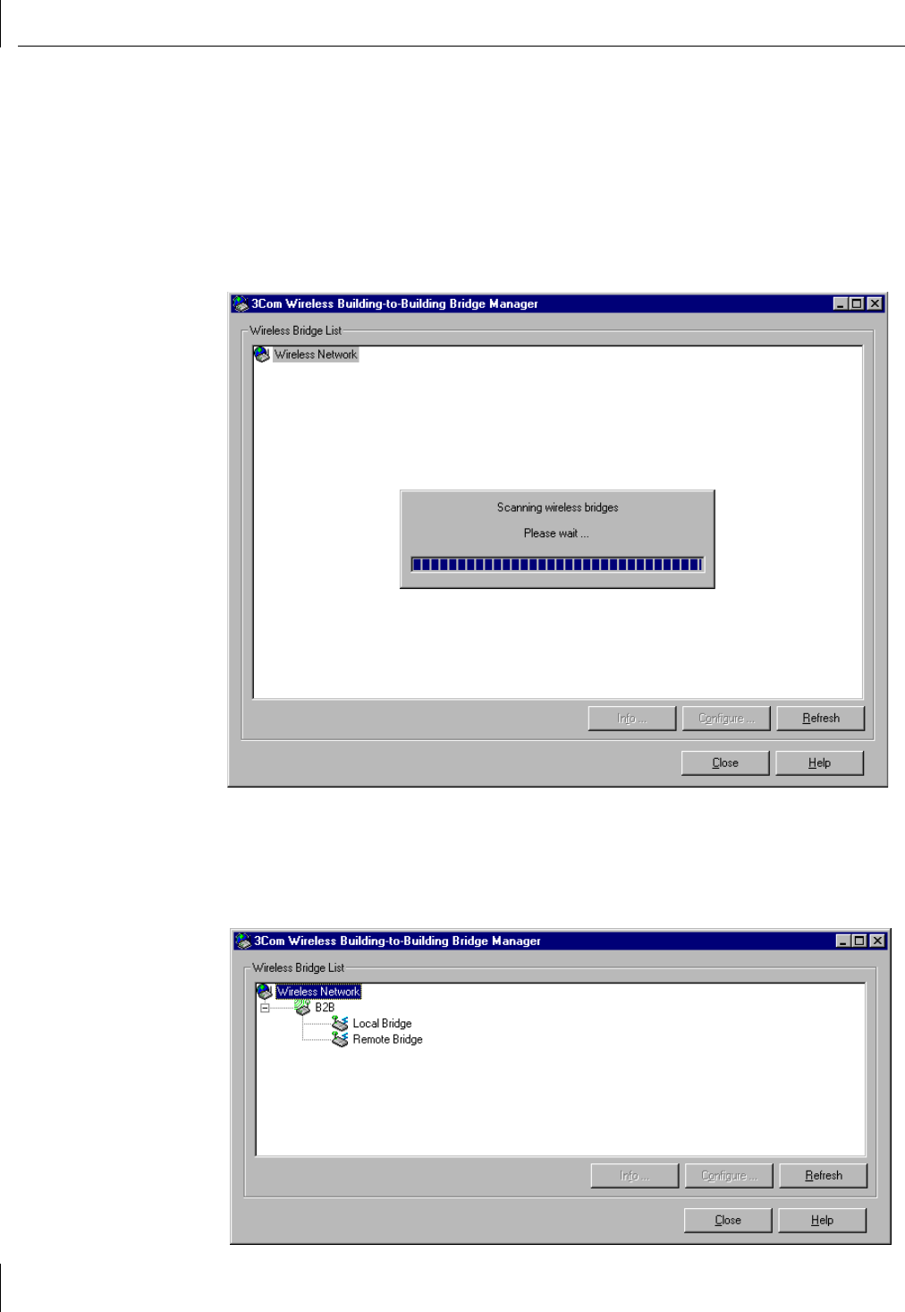
The 3Com Wireless Building-to-Building Bridge Manager screen appears and the
Bridge Manager automatically scans the network for currently accessible bridge
groups. (See the next section,”Scanning for Bridge Groups,” for more information
about bridge groups.)
3Configuring the Bridge
14
Scanning for Bridge Groups
Whenever it is started, the Wireless Bridge Manager automatically scans the local network
to detect currently accessible bridge groups. In this case, a bridge group is defined as all
wireless bridges having the same wireless local area network (WLAN) service area (also
known as an Extended Service Set Identification (ESSID)).
You can force the Bridge Manager to scan the network without having to restart it.
To force the Bridge Manager to scan for accessible bridge groups, click Refresh in the
lower-right corner of the 3Com Wireless Building-to-Building Bridge Manager screen.
After completing the scan, the Bridge Manager displays the detected bridge groups on
the 3Com Wireless Building-to-Building Bridge Manager screen. Also displayed are all the
individual bridges associated with each detected bridge group. You configure a bridge
unit by selecting it on this screen, as described in the next section “Selecting a Bridge to
Configure.”
Selecting a Bridge to Configure
15
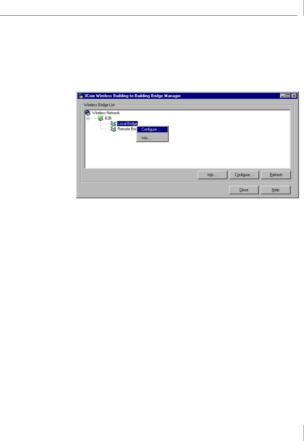
Selecting a Bridge to Configure
To start configuring a wireless bridge unit, display the 3Com Wireless Building-to-Building
Bridge Manager screen (described in “Scanning for Bridge Groups” on page 14) and
follow these steps:
1To show the options available for a listed wireless bridge unit, right-click the displayed
unit name.
2Select Configure.
.
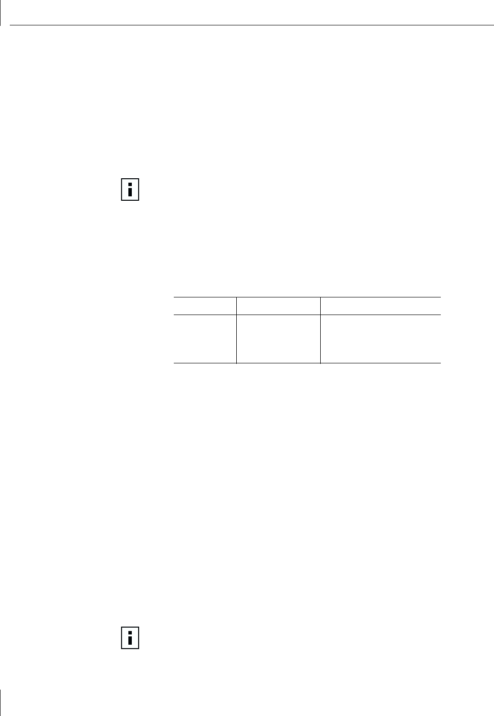
The Wireless Bridge Configuration screen appears (see the next figure), displaying
tabs for Network / Security, Options, Tools, and Info. The functions of these tabs are
described in the following sections.
3Configuring the Bridge
16
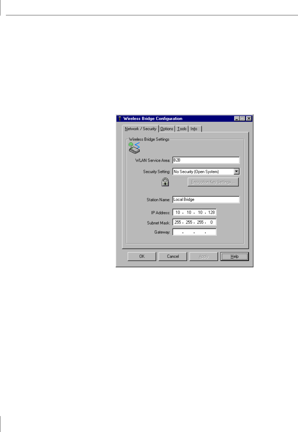
Setting Network and Security Values
You can change network and security settings for the wireless bridge in the Network /
Security tab of the Wireless Bridge Configuration screen. The Network / Security tab lets
you set the following values:
■WLAN service area (ESSID)
■Level of desired WEP (Wired Equivalent Protection) security
■Station name
■IP address
■Subnet mask address
■Gateway address

Setting Network and Security Values
17
Network Settings
Network settings determine the wireless network with which the bridge can associate.
Some wireless LANs are set up with different WLAN service areas. The WLAN service area
is used to specify a unique wireless network. Wireless bridges use the WLAN service area
to connect to a specific network. Only bridges with the same WLAN service area can
associate with each other; they cannot communicate with bridges that have different
WLAN service areas.
To c h a n g e th e Network / Security tab settings:
1Enter the name of a WLAN service area.
The WLAN service area (ESSID) is used to specify a unique wireless network. The
service area name can be up to 32 alphanumeric characters long. Only bridges with
the same WLAN service area can associate with each other; they cannot communicate
with bridges that have different WLAN service areas.
2Use the Security Setting pull-down menu to select one of the following WEP security
settings:
■No Security (Open System)
■40-bit shared key for basic encryption
■128-bit shared key for strong encryption
Using either a 40-bit or 128-bit shared key setting, all wireless bridges in a single
wireless LAN service area (sharing the same ESSID) must share the same security key.
The security settings for any associating bridge pair must match exactly. For more
information about the security settings, see the next section, “Security Settings.”
3Enter the Station Name.
The station name is an arbitrary identifier for each wireless bridge. This value lets you
conveniently identify the bridges with the Wireless Bridge Manager. Assigning a
meaningful station name to each wireless bridge is recommended. Like the WLAN
Service Area Name (step 1), this field uses any alphanumeric combination.
4Enter the IP Address you want to assign to the wireless bridge.
The IP address is the network address that will be used by other computers to
communicate with the wireless bridge. Assigning an IP address to the bridge is
required only if you plan to use Telnet for remote configuration. (See Appendix B,
“Using the Terminal Configurator,” for more information about using Telnet.)
5Enter the Subnet Mask value.
This value defines the range of IP addresses available within your local network.
Assigning a subnet mask address to the bridge is required only if you plan to use
Telnet for remote configuration.
6If your network uses a gateway (router or firewall), enter the Gateway IP address.
You must enter the IP address of your gateway if you plan to use Telnet to administer
the wireless bridge from computers on a different subnet. You may leave this field
blank if no gateway is present or needed. Assigning a gateway address to the bridge
is required only if you plan to use Telnet for remote configuration.
7Click Apply.
When the wireless bridge has joined your wireless network by associating with
another wireless bridge, the radio association LED will light green.
3Configuring the Bridge
18
Security Settings
Enabling security is the best way to protect your data from unauthorized observers. 3Com
recommends using the strongest encryption setting supported by your wireless bridge.
The 3Com Wireless Building-to-Building Bridge supports the following levels of hardware
encryption:
Both basic and strong shared-key security settings use industry-standard 802.11 Wired
Equivalent Privacy (WEP) encryption methods. Using either setting, all wireless bridges in a
single wireless LAN service area must share the same security key. The WEP key settings for
any associating bridge pair must match exactly.
You can set the WEP keys in one of two ways. You can:
■Have the keys automatically generated — Allows you to easily enter any string of
characters (as you would enter a password) that will automatically generate the WEP
keys in hexadecimal notation the same way for every wireless bridge you configure.
■Enter the keys manually — Allows you to use an existing set of encryption keys, but
requires that you manually enter four long series of hexadecimal numbers in exactly
the same way for every wireless bridge you configure.
NOTE: The 128-bit encryption setting may not be available to you, depending on
U.S. export restrictions to your country.
Security Level Description
No Security (Open System) No encryption. The network communications could be intercepted by
unintended recipients.
40-bit shared key Basic encryption.
128-bit shared key Strong encryption.
Setting Network and Security Values
19
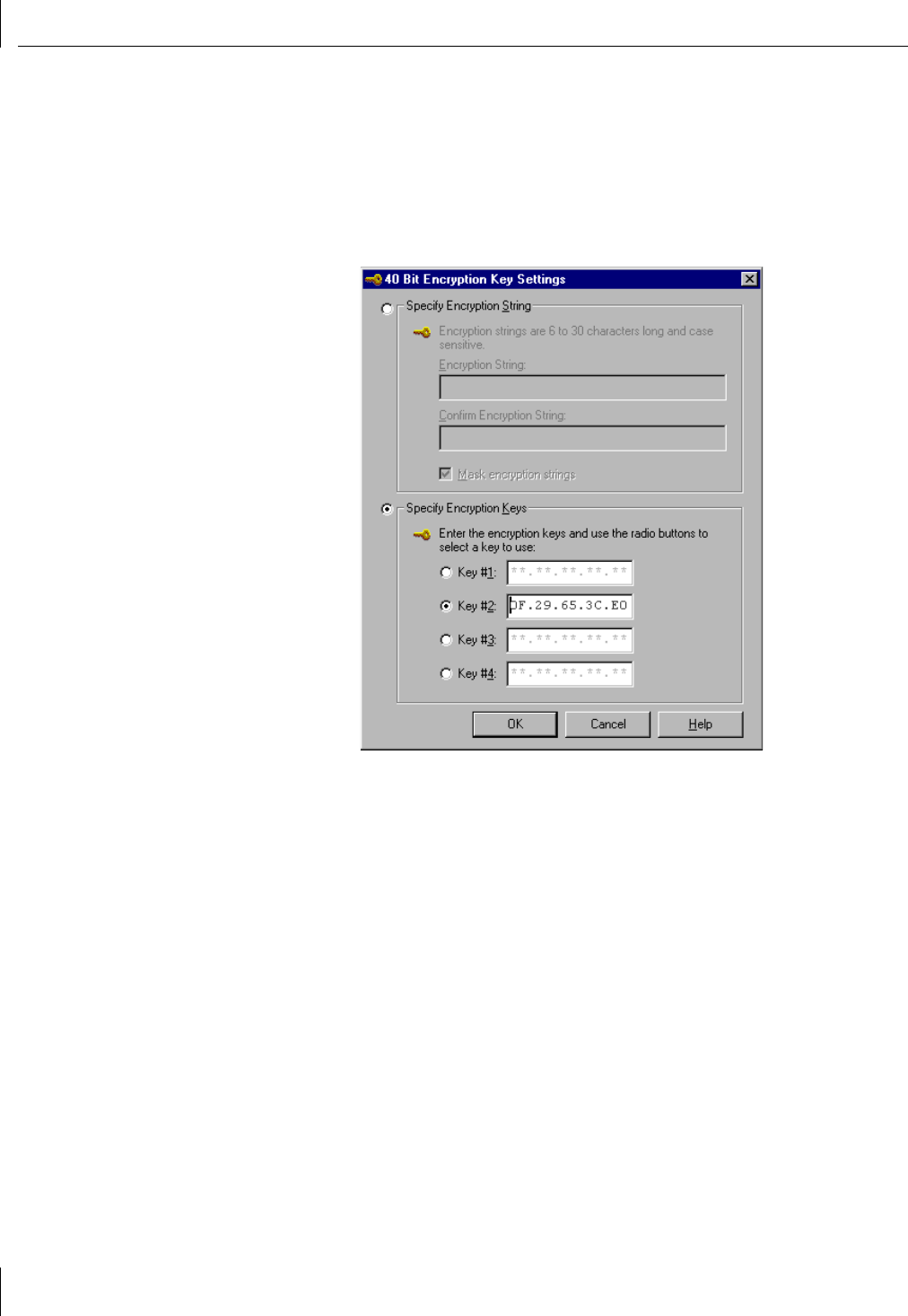
40-bit Shared Key Encryption Settings
Establishing 40-bit shared-key security requires that you set up encryption keys. You can
have the encryption keys automatically generated by entering an encryption string, or you
can manually enter the keys.
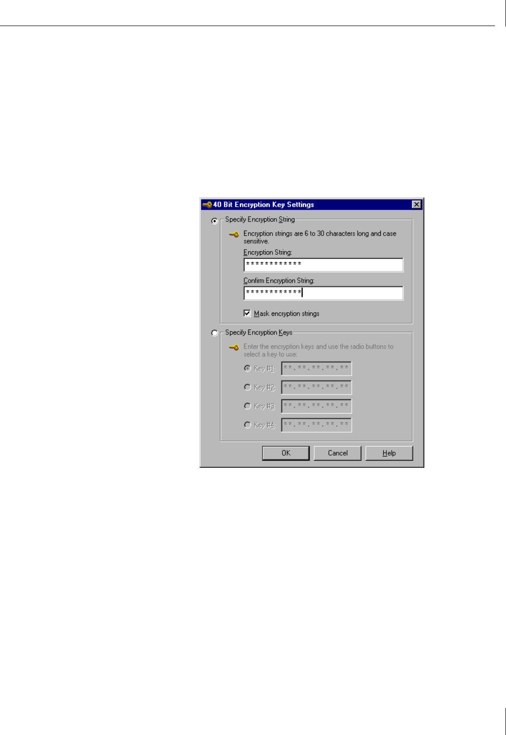
Entering an Encryption String To enter an encryption string that will automatically
generate the WEP keys, follow these steps:
1In the Network / Security tab of the Wireless Bridge Configuration screen, select
40-bit Shared Key from the Security setting list (see step 2 on page 17.)
2Click Encryption Key Settings.
The 40 Bit Encryption Key Settings screen appears.
3Select Specify Encryption String.
4Type the encryption string in the Encryption String field. Retype the encryption string
in the Confirm Encryption String field to make sure that you have entered the string
correctly.
A valid encryption string is a string of characters between 6 and 30 characters long. The
string can be any combination of letters and numbers and is case-sensitive. The string
you enter will automatically generate the actual WEP encryption keys in hexadecimal
notation.
5Click OK when finished.
3Configuring the Bridge
20
Entering the Encryption Keys You can decline to enter an encryption string (as
described in the preceding section) and instead manually enter the WEP keys. To manually
enter the WEP keys in hexadecimal notation, follow these steps:
1In the Network / Security tab of the Wireless Bridge Configuration screen, select
40-bit Shared Key from the Security setting list (see step 2 on page 17.)
2Click Encryption Key Settings.
The 40 Bit Encryption Key Settings screen appears.
3Select Specify Encryption Keys.
4Enter the key settings.
Hexadecimal keys are sequences of hexadecimal digits arranged into four keys.
A hexadecimal digit may be a letter from A to F or a number from 0 to 9. You
must enter settings for all four keys. All four keys must be entered in precisely the
same hexadecimal notation for all the wireless bridges you are configuring for
your network.
5Click one of the radio buttons to select the transmit key to use.
6Click OK when finished.
Setting Network and Security Values
21
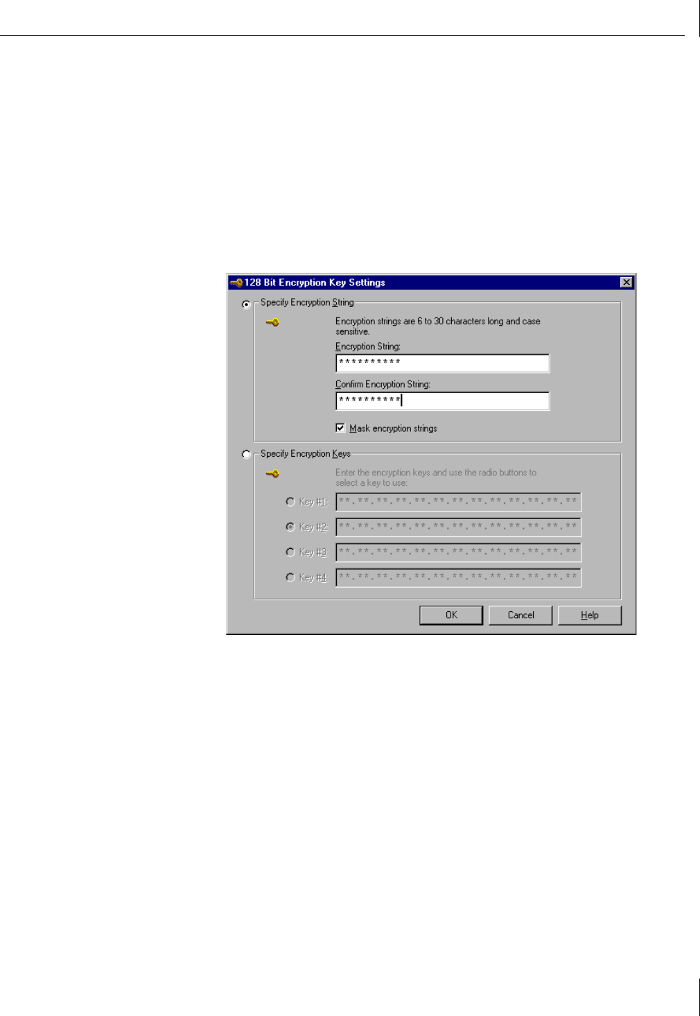
128-bit Shared Key
Establishing 128-bit shared key security requires that you set up encryption keys. You can
have the encryption keys automatically generated by entering an encryption string, or you
can manually enter the keys.
Entering an Encryption String To enter an encryption string that will automatically
generate the WEP keys, follow these steps:
1In the Network / Security tab of the Wireless Bridge Configuration screen, select
128-bit Shared Key from the Security setting list (see step 2 on page 17.)
2Click Encryption Key Settings.
The 128 Bit Encryption Key Settings screen appears.
3Select Specify Encryption String.
4Type the encryption string in the Encryption String field. Retype the encryption string
in the Confirm Encryption String field to make sure that you have entered the string
correctly.
A valid encryption string is a string of characters between 6 and 30 characters long.
The string can be any combination of letters and numbers and is case-sensitive. The
string you enter will automatically generate the actual WEP encryption keys in
hexadecimal notation.
5Click OK when finished.
3Configuring the Bridge
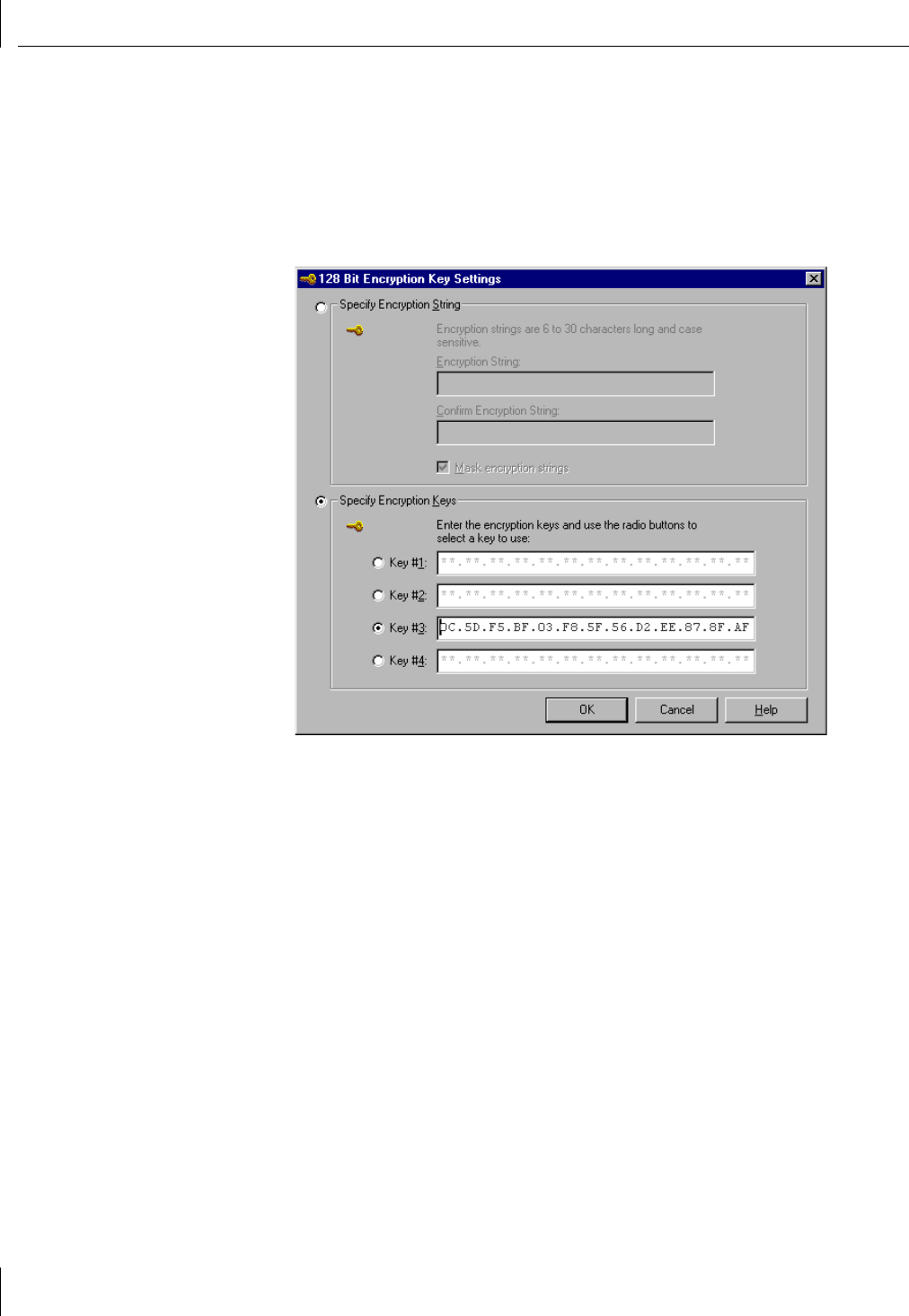
22
Entering the Encryption Keys You can decline to enter an encryption string (as
described in the preceding section) and instead manually enter the WEP keys. To manually
enter the WEP keys in hexadecimal notation, follow these steps:
1In the Network / Security tab of the Wireless Bridge Configuration screen, select
128-bit Shared Key from the Security setting list (see step 2 on page 17.)
2Click Encryption Key Settings.
The 128 Bit Encryption Key Settings screen appears.
3Select Specify Encryption Keys.
4Enter the key settings.
Hexadecimal keys are sequences of hexadecimal digits arranged into four keys.
A hexadecimal digit may be a letter from A to F or a number from 0 to 9. You
must enter settings for all four keys. All four keys must be entered in precisely the
same hexadecimal notation for all the wireless bridges you are configuring for
your network.
5Click one of the radio buttons to select the transmit key to use.
6Click OK when finished.
Setting Network Transmission Options
23
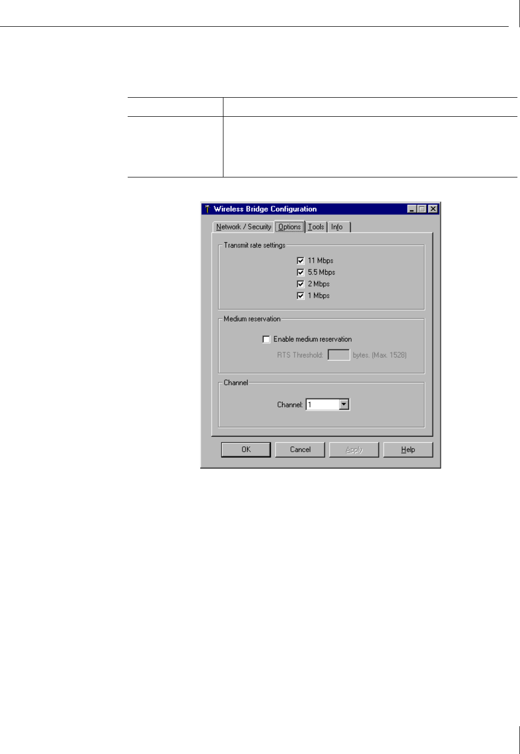
Setting Network Transmission Options
The Options tab of the Wireless Bridge Configuration screen lets you set values for the
following options:
Options Purpose
Transmit rate settings Control the rates at which the wireless bridge makes physical layer
transmissions.
Medium reservation Controls the 802.11 Request to Send/Clear to Send (RTS/CTS) mechanism.
Channel Controls the radio frequency.
3Configuring the Bridge
24
Setting the Transmit Rates
The transmit-rate-settings parameter controls the rates at which the wireless bridge makes
physical layer transmissions. The rates listed are those supported by the 802.11b radio.
These rates refer to the physical layer transmissions, and do not necessarily correspond to
the data throughput that you will achieve. Data throughput is affected by many factors,
including distance, signal quality, and network protocol.
Use the check boxes to specify the allowed transmit rates for the radio. If you select
multiple allowed transmit rates the unit will automatically use the highest available
rate based on signal quality. When the signal quality is poor the radio will drop back to
lower rates.
If you force the radio to a lower rate, then it will operate better with poor signal quality.
If you force the radio to a higher rate, then it will operate only when the signal quality is
high. In general, you should leave this setting at the default of all rates allowed.
The following table shows the allowable combinations of transmit rate settings. You
should use the same transmit rate settings for all wireless bridges sharing WLAN service
area (ESSID):
Setting Medium Reservation
The medium reservation parameter controls the 802.11 Request to Send/Clear to Send
(RTS/CTS) mechanism. It is used to force the radio to perform a Request to Send and
receive a Clear to Send before transmitting packets. One of the bridges in the system acts
as the coordinator for all transmissions. The coordinator issues the Clear to Send messages
for all other bridges that are making Requests to Send. There is not a way to specify which
bridge will be the coordinator.
When medium reservation is enabled you must specify the RTS threshold. The threshold is
the packet length, in bytes, above which the radio will make the RTS and wait for CTS
before sending the packet. For example, if you enable medium reservation with an RTS
threshold of 500, then all packets of length greater than or equal to 500 bytes will not be
transmitted until the radio first issues an RTS and then receives a CTS from the coordinator.
Packets less than 500 bytes will be sent as soon as the channel is free, without first
undergoing the RTS/CTS mechanism.
Setting the Channel
The 802.11 standard specifies a number of different frequency channels. The regulatory
bodies of your country control the frequency channels that you may use. Use the pull-
down menu to see the list of channels supported by your wireless bridge unit.
NOTE: 3Com recommends that you select all the Transmit rate settings (11, 5.5,
2, 1 Mbps) to achieve the best performance.
Combination Settings (On) Description
A 1, 2, 5.5, 11 Mbps 11 Mbps with auto-fallback
B 1, 2 Mbps 2 Mbps with auto-fallback
C 1 Mbps 1 Mbps
NOTE: To ensure operation on a specific channel, all bridges with the same WLAN
Service Area Name (see step 1 on page 17) must have the same channel setting.
25
4Using System Tools and
Viewing Information
This chapter describes various system tools available for use with the 3Com Wireless
Building-to-Building Bridge. The wireless bridge system tools allow you to:
■Write a configuration to a file.
■Reload a saved configuration file to a selected bridge.
■Reset the unit.
■Restore the unit default settings.
■Update the bridge firmware.
■Change the bridge password.
■View log information.
■View the signal strength of packets received by the wireless bridge.
Accessing System Tools
Selecting the Tools tab displays the available system tools for the wireless bridge.
4Using System Tools and Viewing Information
26
Saving and Loading Configurations
Selecting the Tools tab on the Wireless Bridge Configuration screen displays the Load
Config (Configuration) From File and Write Config To File tools. Use these tools to back up
the bridge configuration settings once you are satisfied with them, and recover the bridge
configuration settings, if necessary. For example, if you have to reset the unit to its original
default settings for troubleshooting purposes, you may want to later restore a particular
set of configuration values.
Saving a Configuration
You can write (save) the configuration settings of the wireless bridge to a local file.
This feature allows you to save settings of a known state for backup purposes or easily
configure multiple bridges with the same settings. To save a configuration file, follow
these steps:
1From the Wireless Bridge Configuration screen (see “Selecting a Bridge to Configure”
on page 15), select the To o l s tab.
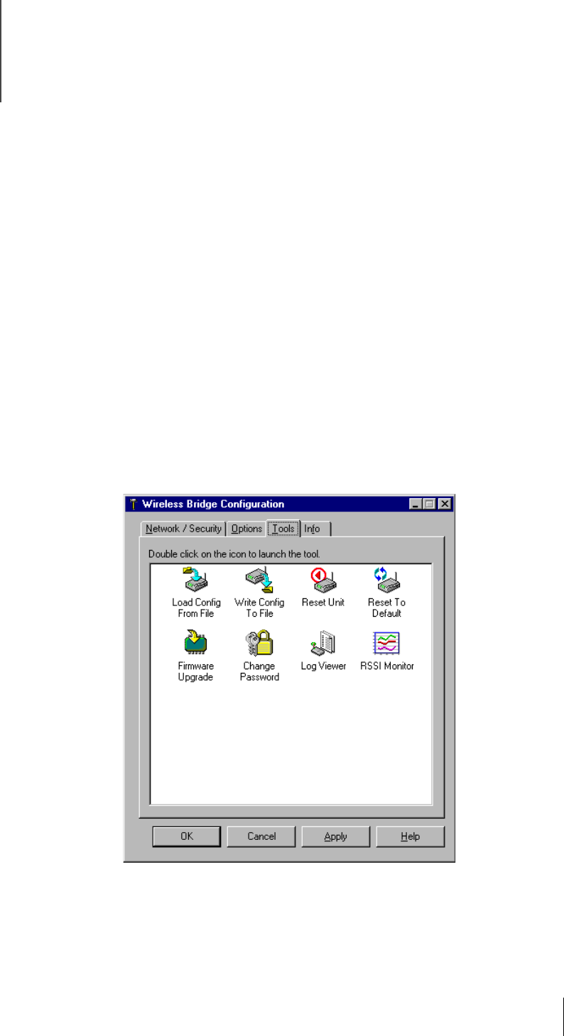
2Double-click the Write Config To File icon.
The Save As screen appears, displaying all the currently saved configuration files.
3Type a name for the saved configuration file in the File name field.
4Click Save to save the configuration.
A message is displayed once the configuration file has been successfully saved.
Resetting the Unit
27
Loading a Configuration
The Wireless Bridge Manager allows you to easily reload a saved configuration file to the
currently selected bridge. To reload a saved configuration file, follow these steps:
1From the Wireless Bridge Configuration screen (see “Selecting a Bridge to Configure”
on page 15), select the To o l s tab.
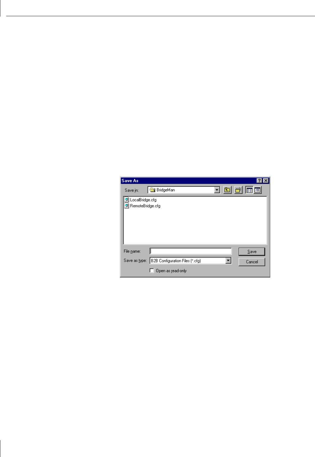
2Double-click the Load Config From File icon.
The Open screen appears, and displays all the saved configuration files.
3Select the saved configuration file from the Open window.
4Click Open to load the configuration.
A message is displayed once the configuration file has been successfully loaded.
Resetting the Unit
If you experience a persistent problem with your wireless bridge, you can perform a reset
of the bridge unit in a way that does not erase your configuration settings. Resetting the
unit from the Reset Unit icon clears:
■Some of the error log (see “Event Log” on page 33)
■The bridge unit forwarding table (see “Forward Table” on page 34)
During the reset, bridging through the unit will be temporarily interrupted, and the bridge
will have to “relearn” the forwarding table.
If resetting the unit does not fix the problem, then you may have to perform a “hard”
reset that completely restores all the bridge configuration settings to their initial factory
default values. (See “Resetting the Unit to Factory Defaults” on page 28.) To help
diagnose the problem, see Chapter 5, “Troubleshooting Bridge Problems.”
4Using System Tools and Viewing Information
28
To reset the wireless bridge unit, follow these steps:
1From the Wireless Bridge Configuration screen (see “Selecting a Bridge to Configure”
on page 15), select the To o l s tab.
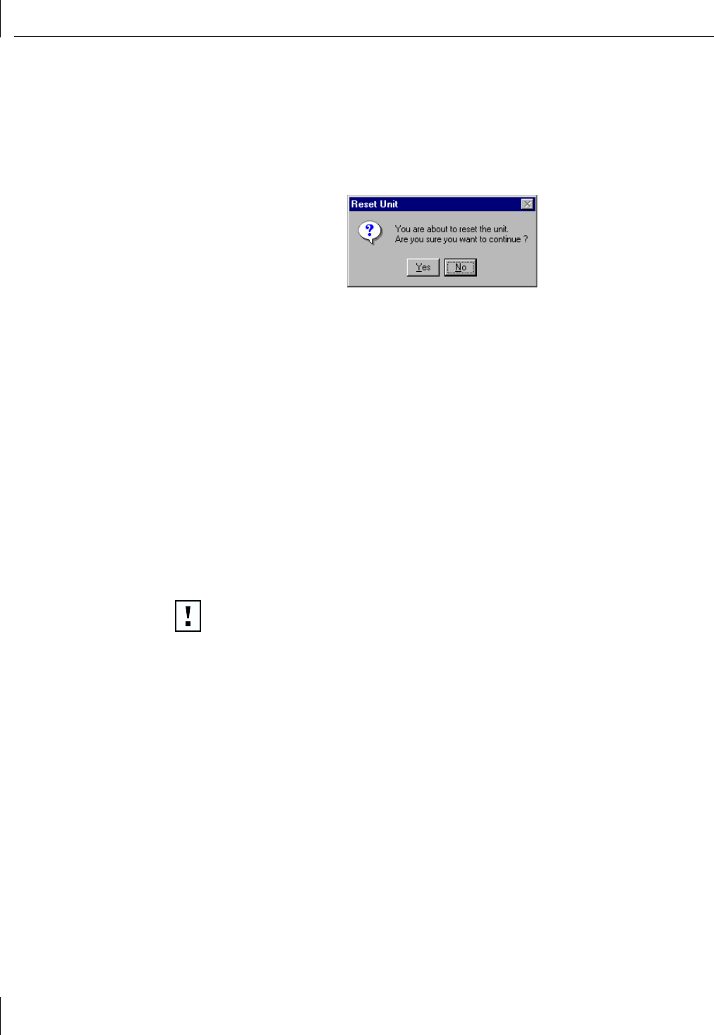
2Double-click the Reset Unit icon.
The Reset Unit screen appears, asking you to verify that you want to restart the
bridge unit.
3Click Yes to restart the unit.
Resetting the Unit to Factory Defaults
If resetting the unit (as described in the preceding section) does not fix the problem,
then you may have to perform a “hard” reset that completely restores all the bridge
configuration settings to their initial factory default values. To help diagnose the problem,
see Chapter 5, “Troubleshooting Bridge Problems.”
You can perform a “hard” reset in two ways to restore all the bridge configuration
settings to their initial factory default values. You can either:
■Double-click the Reset to Default icon from the Tools tab of the Wireless Bridge
Configuration screen. (See the next section, “Using the Reset to Default Icon.”)
or
■Use a paper clip to press the configuration button (labeled Config. in the illustration
on page 10) located next to the serial port on the back panel of the bridge.) (See
“Resetting by Using the Configuration Button” on page 29.)
CAUTION: Resetting to factory defaults resets all wireless bridge configuration
parameters, including the WLAN service area name (ESSID). Resetting to defaults
might leave your bridge in a non-reachable state, depending on your current radio
network setting.
For example, if a reset wireless bridge is not on the same wired LAN section as
your PC, it is possible that the bridge will lose association with the other bridges,
and the configuration utility will no longer be able to communicate with the
bridge. If this situation happens, you must connect the bridge to your PC through
an Ethernet cable. You will then be able to use the Wireless Bridge Manager to set
the WLAN service area name to that of your bridge.
Resetting the Unit to Factory Defaults
29
Using the Reset to Default Icon
To reset the wireless bridge unit configuration settings to their factory default values,
follow these steps:
1From the Wireless Bridge Configuration screen (see “Selecting a Bridge to Configure”
on page 15), select the To o l s tab.
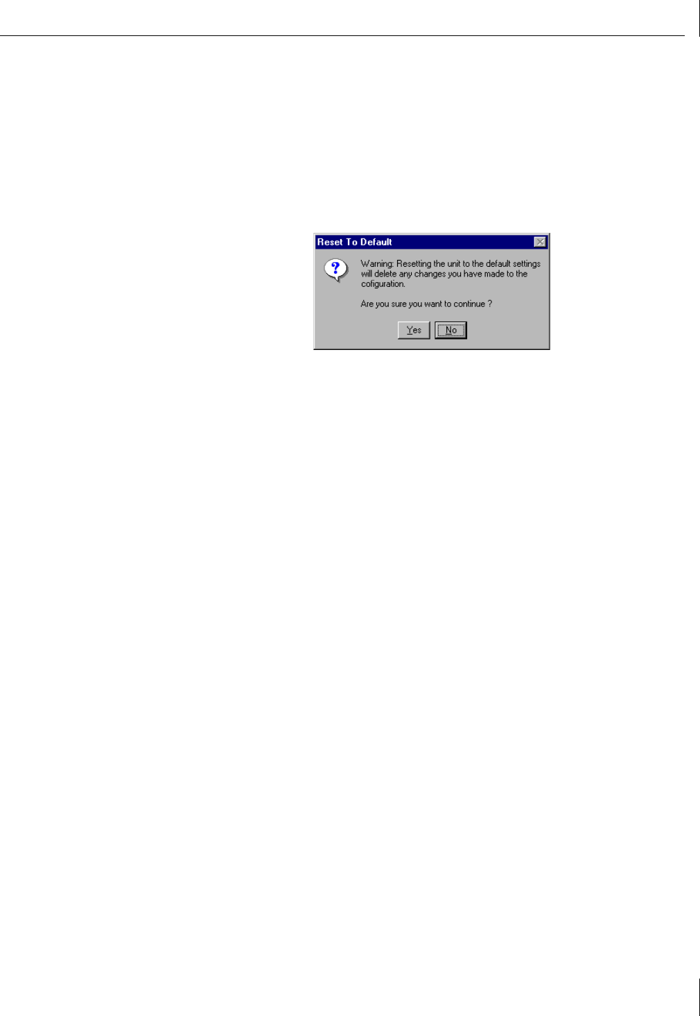
2Double-click the Reset To Default icon.
The Reset To Default screen appears, asking you to verify that you want to restart the
bridge unit.
3Click Yes to restart the unit.
Resetting by Using the Configuration Button
You can also reset the 3Com Wireless Building-to-Building Bridge to factory default
settings without using the Bridge Manager:
1Disconnect power to the bridge.
2Insert one end of an extended paper clip into the small hole labeled Config. (located
near the serial port on the bridge back panel) to press the configuration button.
3While keeping the configuration button pressed, reconnect power to the bridge.
Press the configuration button for at least five seconds after power is applied. The
bridge will be reset to factory defaults once the lights start to blink.
4Using System Tools and Viewing Information
30
Updating the Bridge Firmware
The 3Com Wireless Building-to-Building Bridge ships with the most current firmware
available. Over time, as features are added and problems are fixed, newer firmware may
become available. If you are having trouble with your wireless bridge, it is recommended
that you first upgrade to the latest firmware version.
Follow these steps to update the wireless bridge firmware to the latest version:
1Download the latest version of firmware from http:\\support.3com.com to the
computer that is currently running the Wireless Bridge Manager.
The firmware file has the extension .RMU.
2After downloading the firmware, select the To o ls tab from the Wireless Bridge
Configuration screen (see “Selecting a Bridge to Configure” on page 15).
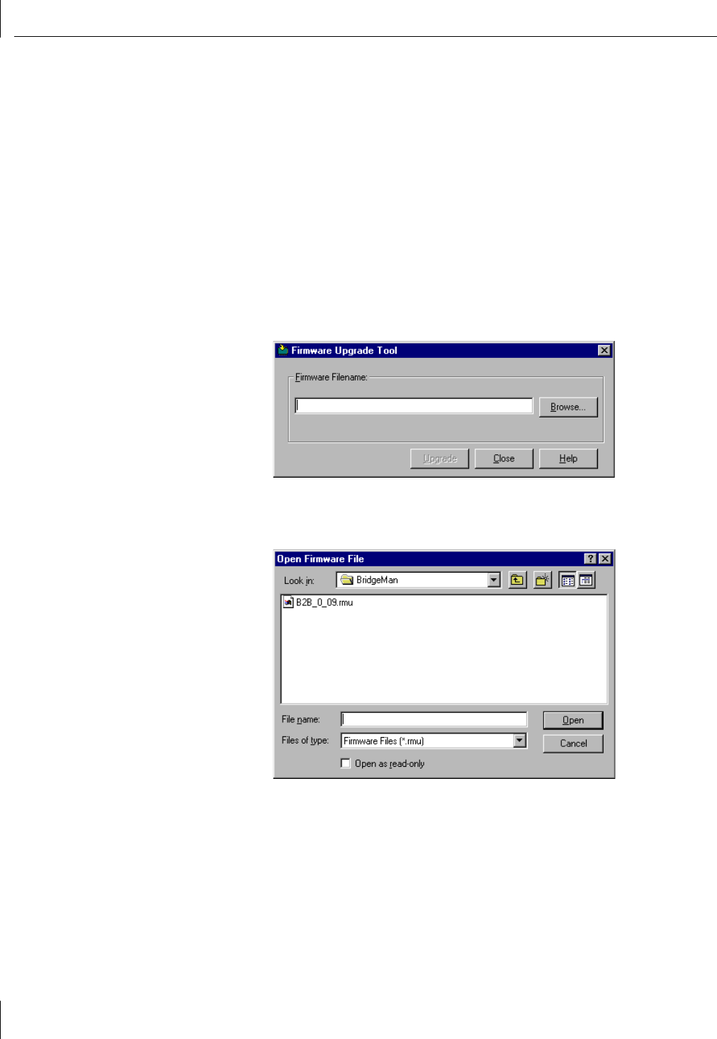
3Double-click the Firmware Upgrade icon.
The Firmware Upgrade Tool dialog box appears.
4If you know the name and location of the file, enter it in the Firmware Filename field,
otherwise click Browse to locate the firmware file on your computer.
Clicking Browse displays the Open Firmware File screen:
Updating the Bridge Firmware
31
5Use the Open Firmware File screen to locate the firmware file. Select the file and
click Open.
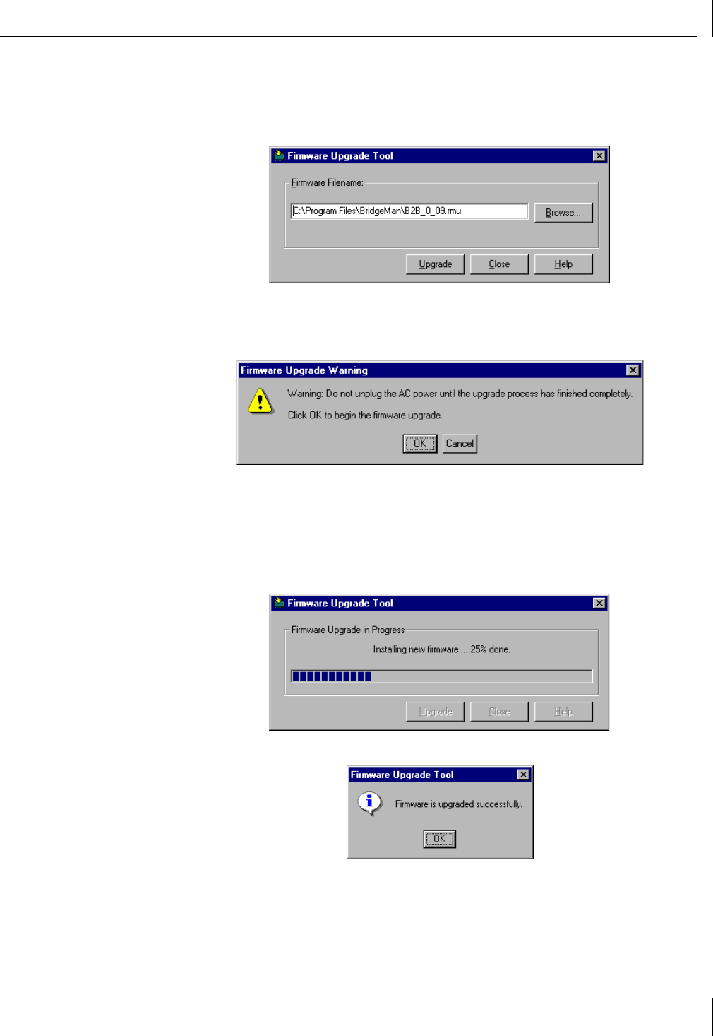
The Bridge Manager fills in the path and file name in the Firmware Upgrade Tool
screen for the file you selected, as shown here:
6Click Upgrade to begin the upgrade process using the selected firmware.
A warning is displayed instructing you not to disrupt power to the unit while the
update is in progress.
7Click OK to continue.
The Bridge Manager first validates the firmware (.RMU) file, checks for components
that should be loaded on the bridge, and then sends the components to the bridge.
A progress indicator is displayed, as shown in the next figure. Firmware installation
can take from 30 seconds to a few minutes depending on the number of components
being updated. A status indicator updates the progress, as shown below.
After the bridge has completely installed the new firmware, a message is displayed.
8Click OK to acknowledge the successful upgrade and return to the Firmware Upgrade
Tool window.
9Click Close to close the Firmware Upgrade Tool window and return to the Tools tab of
the Wireless Bridge Configuration screen.
4Using System Tools and Viewing Information
32
Setting the Password
Setting a password prevents unauthorized users from accessing or changing the settings
for your wireless bridge. You must enter this password each time you reconfigure the
bridge. It is recommended that you set a password for each wireless bridge.
To initially set or change the password, follow these steps:
1From the Wireless Bridge Configuration screen (see “Selecting a Bridge to Configure”
on page 15), select the To o l s tab.
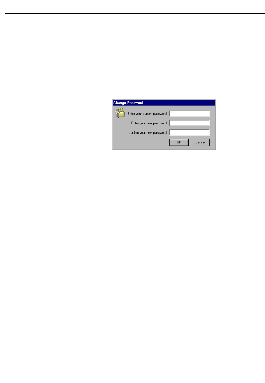
2Double-click the Change Password icon.
The Change Password dialog box appears.
3If you are changing an existing password, type the active password in the Enter your
current password field. (If you are entering a new password for the first time, leave
the Enter your current password field blank.)
4Type the new password in the Enter your new password field. Type the new password
a second time in the Confirm your new password field to verify the accuracy of
your entry.
Entering blank text for the “new password” will remove the active password. If the
active password is removed, the Wireless Bridge Manager will not prompt for a
password.
5Click OK to immediately activate the new password.
Using the Log Viewer
33
Using the Log Viewer
The Log Viewer lets you display:
■The different logs and tables stored on the wireless bridge.
■Status and error messages issued by the wireless bridge.
To display the Log Viewer screen, follow these steps:
1From the Wireless Bridge Configuration screen (see “Selecting a Bridge to Configure”
on page 15), select the To o l s tab.
2Double-click the Log Viewer icon.
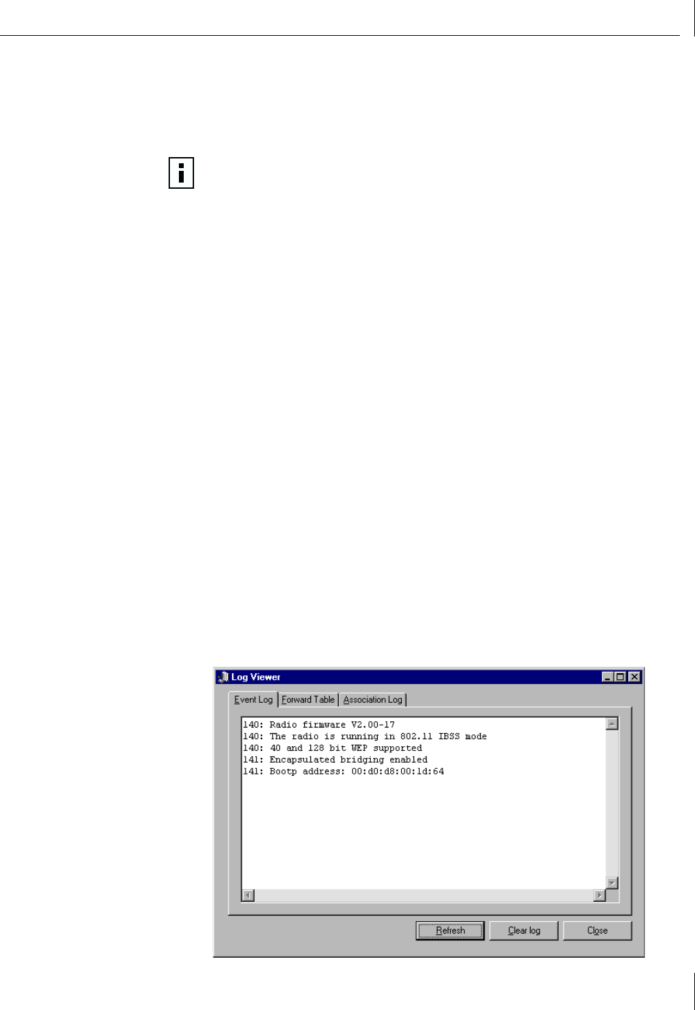
The Log Viewer screen appears, displaying the Event Log tab (see the next illustration).
Switch among the three available logs by choosing the different tabs. The three logs
available through the Log Viewer are:
■Event Log — Displays basic information and status messages generated by the
wireless bridge.
■Forward Table — Displays the MAC addresses that have been seen by the
wireless bridge.
■Association Log — Displays association and disassociation events.
Event Log
The event log displays messages generated by the wireless bridge. Event log messages
include basic information about the bridge hardware and any status messages generated
by the bridge. To clear the entries from the event log, click Clear Log. If the Alert light is
on, clearing the event log turns it off.
The time stamp indicates the number of 10-millisecond periods since the unit was turned
on or reset. For example, a time stamp of 6000 corresponds to a time of 60 seconds, and
a time stamp of 20 corresponds to a time of 0.2 seconds.
See “Diagnosing Problems” on page 39 for more information about troubleshooting
bridge problems using the event log.
NOTE: Viewing the logs may interrupt network connectivity. Therefore, it is
recommended that you try to schedule viewing the logs for a time when the rate
of network traffic is at a minimum, preferably after normal working hours.
4Using System Tools and Viewing Information
34
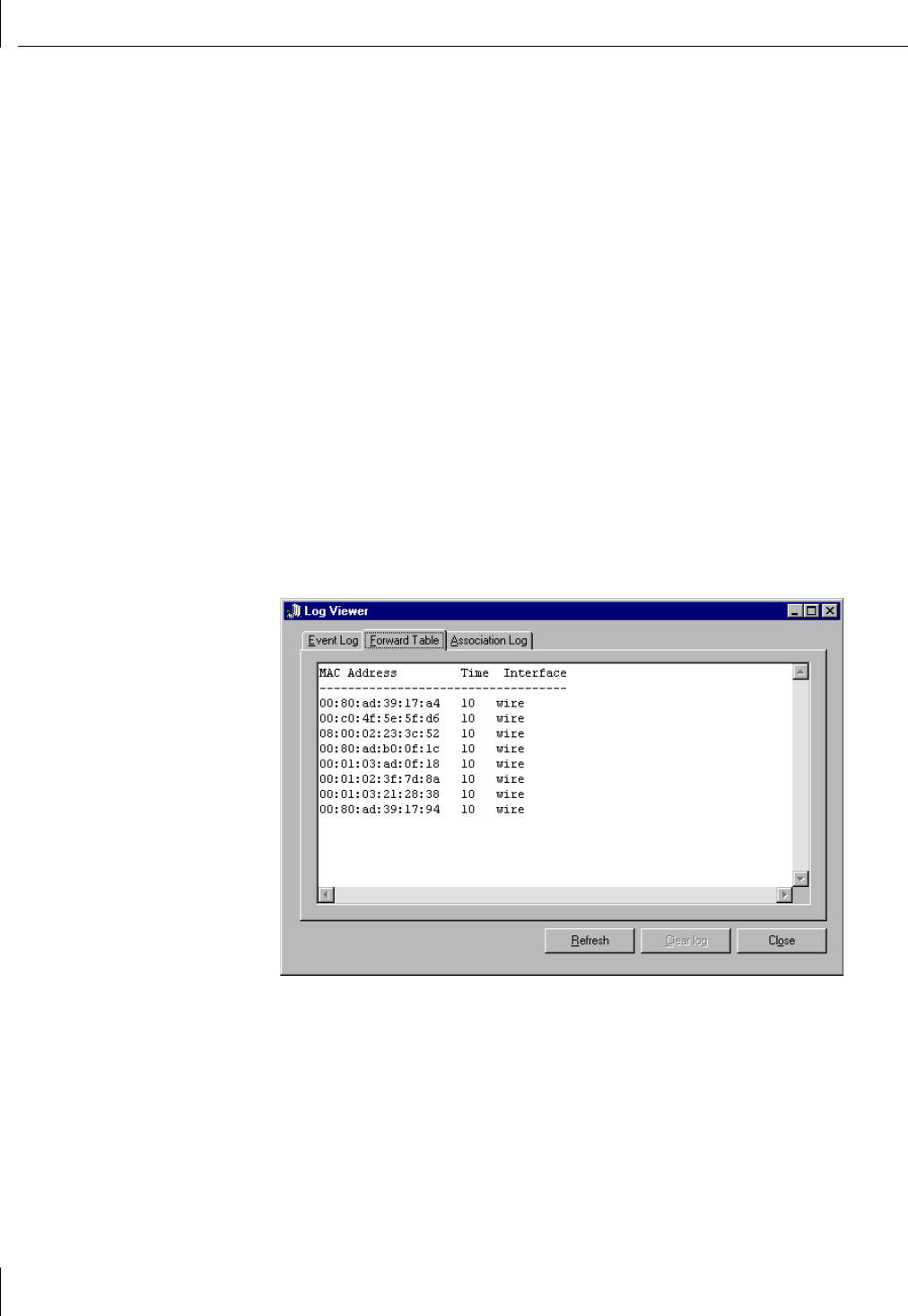
Forward Table
The forward table displays the MAC addresses that have been detected by the wireless
bridge. The table lists the interface, wire (10BASE-T) or radio (Wireless), on which each
MAC address was observed. The time for each entry indicates the number of seconds until
that entry will be removed from the table.
The forward table helps the wireless bridge make efficient use of the radio bandwidth.
The wireless bridge uses the forward table to decide if packets received on the wired
interface should be sent to the radio and transmitted to remote bridges.
The local wireless bridge attached to your LAN uses the forward table to identify traffic
that remains on the local side of the wireless link. The local wireless bridge does not
forward those packets to remote wireless bridges because the forwarding table “knows”
that the source and destination computers are on the local network.
When the wireless bridge detects a new source MAC address, it adds that address to the
forward table and the interface value is set to the interface on which the packet was
received. If there is no further activity for this MAC address, the time for the entry will
decrease until it reaches zero. When the time for an entry reaches zero it is removed from
the forward table.
The forward table can hold 1024 entries; however, the Bridge Manager displays only the
first 20 to 30 entries. These top entries are the MAC addresses with the most recent
activity. To see the complete forward table you must use the terminal configuration
interface, described in Appendix B, “Using the Terminal Configurator.”
Using the Log Viewer
35
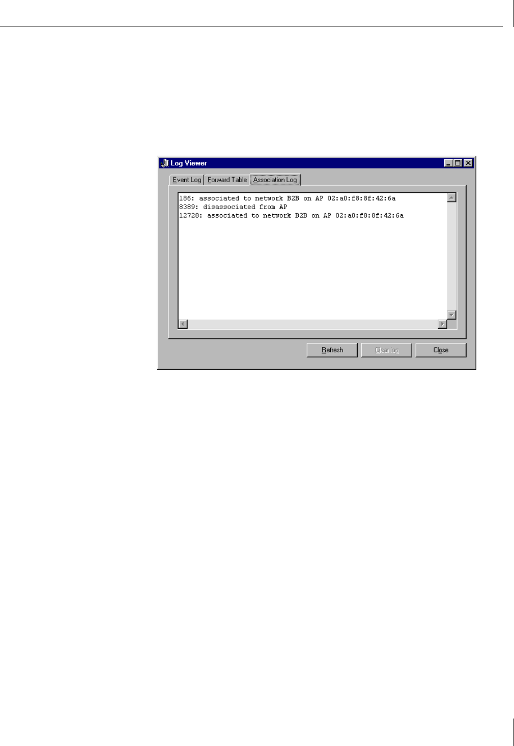
Association Log
The Association Log records association and disassociation events. Each association event
is recorded with a time stamp and, if available, the MAC address and WLAN service area
name of the bridge with which the association was made. Each disassociation event
contains only a time stamp. The time stamp indicates the number of 10-millisecond
periods since the unit was turned on or reset. For example, a time stamp of 6000
corresponds to a time of 60 seconds, and a time stamp of 20 corresponds to a time of
0.2 seconds.
4Using System Tools and Viewing Information
36
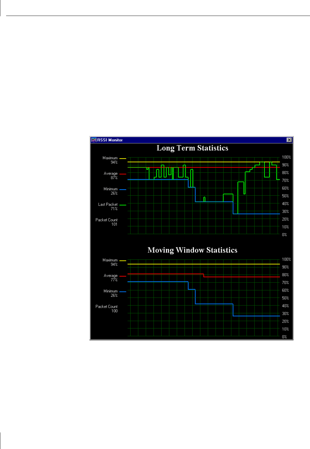
Viewing Signal Strength with the RSSI Monitor
The RSSI Monitor tool provides graphical information about the signal strength of packets
received by the wireless bridge. While this tool is open, the Received Signal Strength
Indicator (RSSI) information is updated each time the unit receives a data packet. This tool
is a useful aid when aligning your antennas. You want to adjust your antennas to achieve
the maximum possible received signal strength. There are no units of value associated
with the signal strength; it is reported as a percent of the maximum attainable value.
To use the RSSI Monitor, follow these steps:
1From the Wireless Bridge Configuration screen (see “Selecting a Bridge to Configure”
on page 15), select the To o l s tab.
2Double-click the RSSI Monitor icon.
The RSSI Monitor appears.
The RSSI Monitor displays two moving graphs:
■Long Term Statistics
■Moving Window Statistics
Viewing System Information
37
Long Term Statistics
The top graph in the RSSI Monitor displays Long Term Statistics. The information in this
graph is reset every time you open the RSSI Monitor. It reports the Maximum, Average,
and Minimum received packet signal strength for all packets since the RSSI Monitor was
opened. This graph also shows the received signal strength of the last packet received.
The Packet Count indicates how many packets have been received since the monitor tool
was opened.
Moving Window Statistics
The Moving Window Statistics are very similar to the Long Term Statistics; however,
Moving Window Statistics are calculated over only the last 100 (maximum) received
packets. The Moving Window Statistics give you an idea of the more recent signal
strength, whereas the Long Term Statistics reflect all observations since the RSSI Monitor
tool was opened. This graph displays the Maximum, Average, and Minimum received
packet signal strength over the last 100 packets. If less than 100 packets have been
received since the monitor tool was opened, then the statistics are calculated over that
number. The Packet Count indicates the number of packets that are included in the
Moving Windows Statistics.
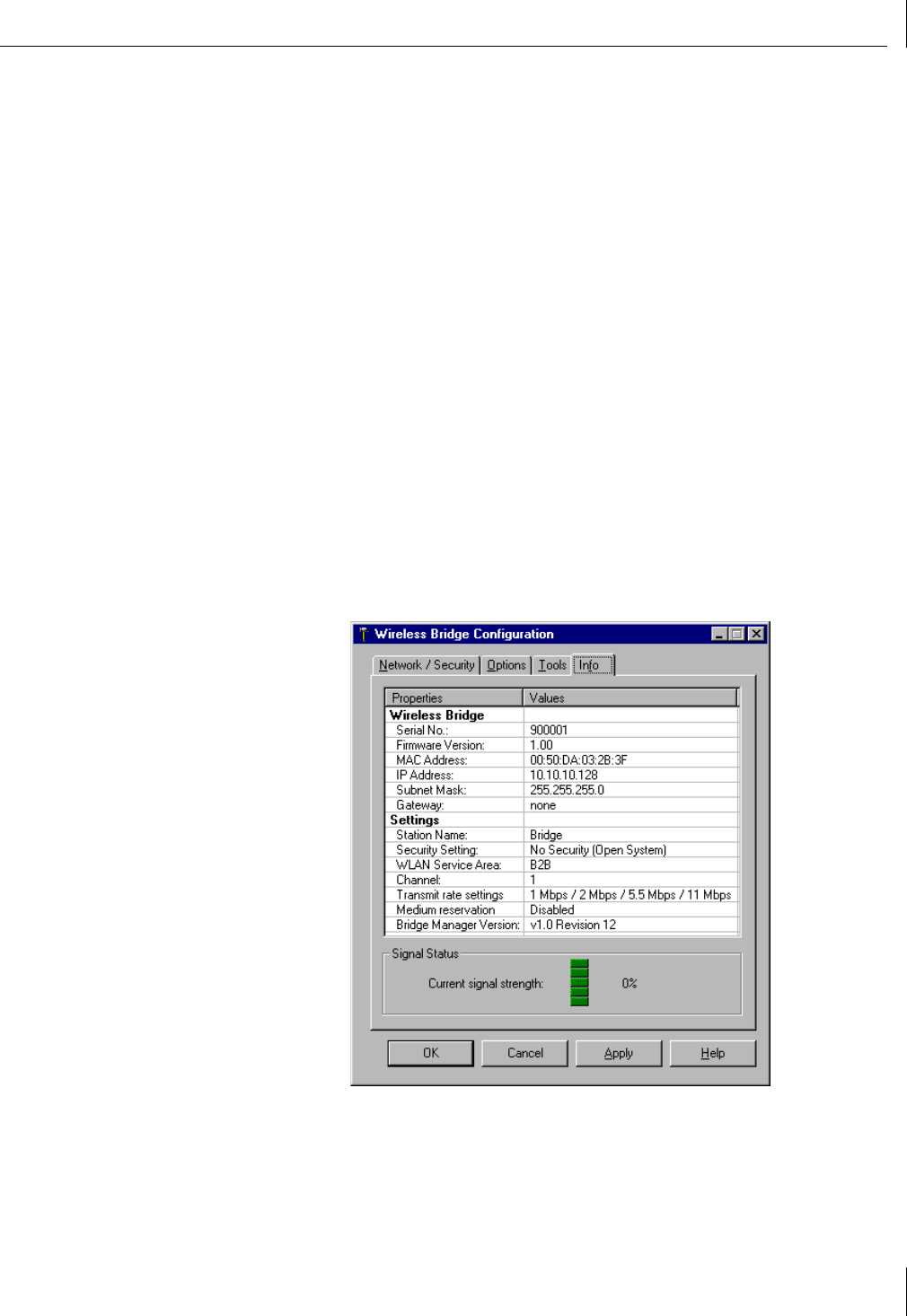
Viewing System Information
Selecting the Info tab on the Wireless Bridge Configuration screen displays information
about the wireless bridge settings and network connection, as shown in the figure below.

39
5Troubleshooting Bridge Problems
If your 3Com Wireless Building-to-Building Bridge is not operating properly, make sure the
bridge is running the latest firmware, and use this guide before contacting 3Com
Customer Support through the 3Com Customer Support Web site:
http://support.3com.com
Upgrading Firmware
If you have any trouble with your bridge unit, go first to the Web site shown below and
download the latest version of the 3Com Wireless Building-to-Building Bridge firmware.
You can find firmware upgrades at the 3Com Customer Support Web site:
http://support.3com.com
See “Updating the Bridge Firmware” on page 30 for detailed instructions.
Diagnosing Problems
Error Indicator Problem Solution
The Power LED is off or the
power light is blinking.
The wireless bridge is not
receiving power properly.
Verify that all physical connections are securely in place. Contact Customer
Support if the problem persists.
The Alert LED is on. There is a configuration or
software alert condition.
Check the System Event Log to determine the cause. (See “Event Log” on
page 33.) See the Event Log Error Table for details. Use the Clear Event Log
option to clear the event log and turn off the Alert LED.
The wireless bridge is
connected to an Ethernet
cable, but the Ethernet link
LED is not on.
There is an invalid
connection to Ethernet.
Verify that both ends of the cable are plugged in securely. If the wireless
bridge is attached to a hub, a crossover Ethernet cable must be used. If the
bridge is attached directly to an Ethernet device (for example, a PC or
Ethernet printer), it must be a straight-through cable. Verify that you are
using the correct cable. If you are using the correct cable, verify that you
are connecting the bridge to a 10BASE-T Ethernet device. The wireless
bridge does not support 100BASE-T.
The Wireless LED is off and
the Alert LED is off.
The bridge is not linking to
other bridges.
Verify that the WLAN service area name is set to match the WLAN service
area names of the other bridges in the network. Verify that the antenna
cable is firmly attached to the SMA port on the bridge and to the
connector of the antenna.
If you are using flat-panel antennas, verify that the panel faces are parallel:
the panel faces must be directly facing each other.

5Troubleshooting Bridge Problems
40
Handling Event Log Errors
The following table lists event log errors. (See “Using the Log Viewer” on page 33 for
more information about accessing the event log.) All entries in the event log are preceded
by a number. This number is a time stamp used by Customer Support, but is not relevant
to looking up items in this table.
Handling Terminal Configurator Error Codes
See Appendix B, “Using the Terminal Configurator,” for detailed information about using
the Terminal Configurator method to configure your 3Com Wireless Building-to-Building
Bridge.
Error Code Description
UART Error – No Rx Buffer
Available
Data is being sent to the UART at a rate faster than it can clear its receive buffers, and data is being lost.
Note that if you are using the serial port menu system for configuration, flow control will not be
enabled in the wireless bridge. To avoid getting this error while in the serial port configuration system,
simply type slower.
Initialization of interface
"lan0" failed.
The bridge could not be initialized.
Try each of the following steps in order. If any of these steps succeeds, there is no need to perform any
of the later steps; otherwise continue to the next step.
1Reset the wireless bridge.
2Unplug the power, wait for approximately 30 seconds and then reapply power.
3Reset the wireless bridge to the factory default configuration and reset the wireless bridge.
4Contact 3Com Customer Support if the problem persists.
Error Code Description
Xxxx: [yyyy]:
section does not exist
Section named yyyy in configuration file named xxxx was missing.
Save your current configuration (if applicable). Reset the wireless bridge configuration to factory
defaults. Reset the wireless bridge. Restore configuration (if applicable).
Xxxx: [yyyy]: “zzzz”:
entry refers to non-existent
section
Entry zzzz refers to a section that is not located in file xxxx.
Save your current configuration (if applicable). Reset the wireless bridge configuration to factory
defaults. Restore configuration (if applicable).
Xxxx: [yyyy]: "zzzz":
entry does not exist
Entry zzzz in section yyyy of file xxxx was missing.
Save your current configuration (if applicable). Reset the wireless bridge configuration to factory
defaults. Reset the wireless bridge. Restore configuration (if applicable).
Xxxx: [yyyy]: "zzzz":
entry is invalid
Entry zzzz in section yyyy of file xxxx contains an invalid value.
Check the entry in the configuration for zzzz. If you cannot find zzzz in the wireless bridge Bridge
Manager program, you may have to use the serial port or Telnet configuration menus.
Xxxx: <[yyyy]zzzz>:
Unable to add route.
Route values are out of range compared to the interface values.
Set the route value to “automatic.” If “automatic” does not work for your wireless bridge, check the
values you set for the route to make sure they correspond to your other IP parameters.
Xxxx: file does not exist. Configuration file could not be found.
Reset the configuration to factory defaults, and reset the wireless. If the problem persists, contact
3Com Customer Support.

41
ATechnical Specifications
Supported Standards
Network Standard
■IEEE 802.11b1
Network Architecture Types
■Bridge 802.3 to 802.11b
Network Connection Type
■10BASE-T
Bridging Protocol
■MAC layer encapsulation
Encryption
■40- and 128-bit WEP encryption, shared key
Security
■VPN pass through
Power Specifications
Available Transmit Power Settings
■300 mA, typically
1.While the 3Com Wireless Building-to-Building Bridge conforms with the IEEE
802.11b standard, it is not compatible or interoperable with other IEEE 802.11b
devices.

ATechnical Specifications
42
Radio Specifications
Frequency Band
■2.4 GHz
Range
■Transmit and receive information up to 2.6 miles (4,146 meters) between wireless
bridges (depending on antenna selection)
Wireless Medium
■DSSS
Media Access Protocol
■CSMA/CA
Modulation
■DSSS
Operating Channels
■1 through 11 (U.S.)
Nonoverlapping Channels
■1, 6, and 11
Sensitivity and Data Rate
Receive Sensitivity
■11 Mb: -81 dBm
■5.5 Mb: -84 dBm
■2 Mb: -85 dBm
■1 Mb: -87 dBm
Data Rates Supported
■11, 5.5, 2, 1 Mbps
Configuration and Management Features
Local Configuration
■GUI console
Remote Configuration Support
■GUI, Telnet

Dimensions
43
Dimensions
Length: 6.20 inches (157 mm)
Width: 3.89 inches (99 mm)
Height: 1.10 inches (28 mm)
Environmental
Environment Limits
Storage temperature -20° to +70° C (-4° to 158° F)
Operating temperature -20° to +55° C (-4° to 131° F)
Humidity 95% maximum, Non-condensing
Operating altitude -100 m to 3,000 m (-328 ft to 9,840 ft)
Transportation/storage altitude -100 m to 4,500 m (-328 ft to 14,800 ft)
Electrostatic discharge ±15 kV, air
±8 kV, contact
±2 kV, pin
Power supply noise and interference 70 mV rms, 30 Hz to 400 MHz

45
BUsing the Terminal Configurator
You can use the Terminal Configurator as an alternative method to configure your
3Com Wireless Building-to-Building Bridge in the event that the Wireless Bridge Manager
configuration utility (Chapter 3) is not available. The Terminal Configurator is a text-based
configuration method that lacks many of the features of the Bridge Manager. The terminal
configurator can be accessed using a direct serial or Telnet connection.
When using a direct serial connection, the wireless bridge communicates with a
serial terminal or a computer that is running terminal emulation software—such as
HyperTerminal, ProComm, or Telix. You can configure the bridge using a direct serial
connection at any time, regardless of the current wireless bridge settings.
When using a Telnet connection, the unit communicates using TCP/IP with a computer
running a Telnet client program. A Telnet connection can be used to configure wireless
bridges outside of your local area network, when the configuration utility cannot be used,
because the TCP/IP communication is routable.
Establishing a Direct Serial Connection
This method of configuring and managing a 3Com Wireless Building-to-Building Bridge
uses a serial cable connected from the wireless bridge to a computer running terminal
emulation software. HyperTerminal is one of the most widely used terminal emulation
programs because it is standard software included with all recent Windows-based PCs.
Use the following instructions to configure your wireless bridge using the HyperTerminal
program.
1Complete steps 1-10 of the hardware installation procedure in Chapter 2, “Installing
the Hardware and Software.”
2Connect a serial cable to your computer’s serial port. Make note of the PC’s COM port
into which you plugged this cable. Plug the opposite end of the serial cable into the
serial port on the wireless bridge.
3On your desktop, click Start.
4Click Programs.
5Click Accessories.
6Click Hyperterminal.
7Double-click the file labeled hypertrm.exe.
The Connection Description screen appears. This screen allows you to enter a
connection name (any alphanumeric combination) in the Name field. In addition,
the Connection Description screen has an Icon field. Leave the highlighted icon at its
default setting.
8Click OK to proceed with Hyperterminal. Use the Cancel button to terminate
Hyperterminal.
The Phone Number screen appears. The Country Code, Area Code, and Phone
Number fields should be blank by default. Leave these fields at their default settings.
9In the Connect Using field, select the COM port currently used by the RS-232 cable.

BUsing the Terminal Configurator
46
10 Click OK.
The COMx Settings screen appears.
11 Select 9600 in the Bits per second field. Leave the default of 8 selected for the Data
Bits field. Parity should be left at its default of None. The Stop bits setting should be
left at its default of 1.
12 Select None for the flow control option.
13 Click OK after all of the COM settings have been chosen.
The next screen will appear blank.
On some Windows platforms (such as Windows 98) you will have to save the settings,
quit Hyperterminal, and then restart with the saved settings to allow them to
take effect.
14 To start the Configuration Utility, insert one end of an extended paper clip into the
small hole labeled Config. (located next to the serial port on the wireless bridge) to
press the configuration button.
The Terminal Configurator appears on the screen. You have successfully opened a
direct serial connection to the Terminal Configurator.
If the wireless bridge is connected to power, but it does not respond within a few
seconds after pressing the configuration button, disconnect power for a few seconds.
Next, reconnect power and use the paper clip to press the configuration button again.
If the terminal displays random characters, check the baud rate and bit settings in
your terminal emulation software to ensure 9600 baud, 8 data bits, no parity, and
1stop bit.
Establishing a Telnet Connection
This method will open a Telnet connection to the Terminal Configurator on port 23, which
is the default for most Telnet programs. However, this works only after the wireless bridge
has been assigned a TCP/IP address. If you need to assign an IP address to the bridge, you
will need to use either the Windows Bridge Manager or the Terminal Configurator using a
direct serial connection.
1Click Start.
2Click Run…
3Ty pe :
telnet xxx.xxx.xxx.xxx
where xxx.xxx.xxx.xxx is the IP address of the unit you want to configure.
The Terminal Configurator appears on the screen. You have now successfully opened
a Telnet connection to the Terminal Configurator.
NOTE: If, after performing this step, the wireless bridge does not respond with
the configuration mode Main Menu, verify that there is not a cable problem by
pressing the Enter key on the PC and observing the Serial LED. Each time the key
is pressed, the Serial LED should blink faintly and quickly. If the Serial LED does not
blink, there may be a problem in the cable connection. If the Serial LED blinks
when the Enter key is pressed and the unit does not respond, check to see if the
serial configuration is set to 8 data bits, no parity, 1 stop bit.

Using the Terminal Configurator
47
Using the Terminal Configurator
Once you have established a connection to the Terminal Configurator, you will see the
Main Menu. Use the arrow keys to move the highlighted bar between entries. If the arrow
keys do not work, you can move the bar by holding down the Control key while pressing
N (for Next) and P (for Previous) to move the bar. To select an entry, press Enter.
To modify the configuration, as described in the following sections, select Edit
configuration. Another menu, listing available files to edit, will then appear. Selecting one
of the available files will start an editor that you can use to modify the file. File selection
and editor operation are described below.
After you have finished configuring the wireless bridge, select Reset the Unit, and then
answer Ye s to the confirmation. Selecting Yes will reset the device, allowing the new
configuration to take effect, as well as place it into operating mode. The wireless bridge
will then use your new configuration.
Main Menu Overview
The Main Menu provides the following options:
■Resume operation
Exits from terminal configuration mode. If you edited any configuration files, the
changes will not take effect until you reset the bridge. Use the Reset the Building to
Building Bridge option off the Main Menu to reset the bridge.
■Edit configuration
Displays a list of files to edit. Descriptions of the files and their contents are below.
■View configuration for capture
If you select this option, you will have an opportunity to enable capture mode in your
terminal software. It will then display all configuration settings and give you the
option to disable capture mode. You can use this option to keep a record of the
settings made for a particular wireless bridge unit, or to generate a file if you need
to contact 3Com Customer Support.
■Reset configuration to default
This option allows you to set all configuration files to their factory default settings.
■View forwarding database
Lists the MAC addresses of all network nodes detected, and the network interface on
which they were last listed.
■View roaming log
Lists association and disassociation events for this wireless bridge.
■View system error log
Shows a list of status messages, if any have occurred. Use this option if the Status LED
is lit to see what kind of message the wireless bridge is generating.
■Clear system error log
Removes all messages from the system event log described above.
■View RSSI Information
Displays received signal strength statistics.
■Reset the unit
Performs a hardware reset. Use this option after making configuration changes to
allow the changes to take effect.

BUsing the Terminal Configurator
48
Edit Configuration Menu Overview
The Edit Configuration Menu contains three selections:
■Return to Main Menu
Goes back to the previous menu selections.
■System
Displays the editor screen with the configuration file for system options.
■Bridged Ethernet (lan0)
Displays the editor screen with the configuration file for the radio parameters and IP
network settings.
Using The Editor
Selecting one of the configuration files above will bring that file into the editor. Once
inside the editor, you may use arrow keys to move the cursor around. If the arrow keys do
not work with your terminal emulator, press Ctrl+P for up [previous], Ctrl+N for down
[next], Ctrl+B for left [back], and Ctrl+F for right [forward] for cursor motion.
For faster motion, press Ctrl+A to jump to the beginning of the line, and Ctrl+E to jump
to the end. (Those familiar with the Emacs editor should feel comfortable with these
keystrokes.)
To make changes in the editor, simply move the cursor to the point you want to change
and start typing. You can delete text behind the cursor by moving the cursor to the
position immediately following the character you want to remove, and then by pressing
either the Backspace or Delete keys, or by typing Ctrl+H. To delete text in front of the
cursor, press Ctrl+D. To delete text from the cursor to the end of the line, press Ctrl+K.
After editing is completed, save these changes by pressing Ctrl+W. After the changes are
saved, the Edit Configuration menu will return to the screen. Although changes will be
saved, they will not take effect until you power the wireless bridge off and back on. If you
decide that you do not want to save the changes you have made, press Ctrl+X. The editor
will ask you for confirmation, and then will return you to the Edit Configuration Menu.
Screen corruptions or confusions may occur due to many terminal emulation software
packages not emulating VT100 correctly. If the screen display becomes corrupted or
confused as you type, press Ctrl+L to force a screen to redraw the image.
Configuration File Format
Those familiar with the Windows WIN.INI file format will recognize the format of the
configuration file. The file is divided into sections that define a particular grouping of
options. Each section contains a section header at the top, shown as a string of text
surrounded by square brackets: [ ]. This string is the section title. After each section
header, there is a list of entries containing equal signs. The text before the equal sign is a
key and the text after the equal sign is the value. Changing the value of different keys is
how configuration changes are performed.
Comments may be stored in the configuration file by inserting a pound sign (#) before the
text to be added. This allows room for an explanation as to why certain settings have been
made, who made the changes, etc. You may write anything in a comment, but the
comment ends at the end of the line. You can create multi-line comments by inserting
the # at the beginning of each line. For example:
# This is a comment.
# This is line #2 of the comment.
this = no comment
# But this is one.

File Contents
49
File Contents
System
[configure]
This section contains settings that pertain to the operation of the Configuration menus.
Currently, there is only one: password.
■password This setting allows the creation of a password that will be asked for
upon entry to the Configuration screen. Up to 15 alphanumeric characters will
be accepted. Do NOT use any characters other than numbers and letters in this
password. Although the password is not hidden from the screen while editing, it will
be hidden when entering configuration.
[bridge]
This section contains variables that are not specific to the radio.
■AP refresh period This parameter has a default value of zero, which disables this
function. Leave the AP refresh period at its default setting unless you are instructed to
do otherwise by 3Com Technical Support.
■encapsulation This parameter has a default value of on allowing bridging to occur.
Leave the encapsulation set to its default value unless you are instructed to do
otherwise by 3Com Technical Support.
Bridged Ethernet (lan0)
[hardware]
This section contains settings for the actual wireless bridge radio hardware.
■ESSID This parameter specifies the wireless network with which the wireless bridge
will be connecting. Alphanumeric values may be used in this field. All wireless bridges
must have the same ESSID to form a connection.
■station name This parameter names an individual wireless bridge. The station
name is used only for convenience of the network administrator and does not impact
device operation. You may use any alphanumeric name.
■mac address This parameter specifies Media Access Control, which is a unique
alphanumeric address that defines each node of the network. This address should
always be set to the default value of universal.
■operating mode This parameter specifies the operating mode, which should
always be set to the default value of ibss.
■medium reservation This parameter controls the 802.11 RTS/CTS threshold.
The default value is none, which disables medium reservation. Specify a packet
length, in bytes, to enable RTS/CTS medium reservation for packets larger than the
indicated size.
■channel This parameter selects the channel setting for the radio. All wireless
bridges in a single network should have the same channel setting.
■mac timeout This parameter controls the low-level MAC timeout. Do not change
this parameter from its default value of 324 unless instructed to do so by 3Com
technical support.
NOTE: Activating the refresh period does not impair the performance of the
wireless bridge.

BUsing the Terminal Configurator
50
■transmit rate This parameter controls the data rate at which the radio transmits.
Legal values are: 1, 2, 5, and 11.
■antenna diversity This parameter controls antenna diversity. The wireless bridge
has only a single antenna, so this parameter should always be kept at its default value
of no.
■enable encryption This parameter indicates whether WEP encryption by the radio
is desired or not. Setting of the various encryption options is done in the [encryption]
section.
[encryption]
This section contains the configuration parameters that are used when encryption is
enabled. If encryption is not enabled, these parameters have no effect on the wireless
bridge operation.
■transmit key This value sets which of the following keys are used to encrypt
transmitted data. The default setting for this value is 1.
■encryption key 1-4 This value is one of the keys to use for encrypting and
decrypting data on the radio. The key should be specified as either a 10-digit or a
26-digit hexadecimal number. Note that the number should always have a 0x before
the hexadecimal digits. Use 10 digits for a 64-bit key, and 26 digits for a 128-bit key.
[rmp]
This section contains only a single low-level configuration parameter.
■ethertype This value should be changed only if requested by
3Com Technical Support.
[bootp]
This section contains parameters to configure and enable bootp for the wireless bridge.
You can configure the wireless bridge to determine its IP information from a bootp server.
When enabled, the wireless bridge attempts to get its IP Address, Netmask, and Gateway
information from the bootp server.
■enable bootp This parameter should be set to Yes to enable bootp. Default value
is No.
■server ip address This parameter should be set to force the wireless bridge to get
bootp information from a specific server. Using the default value causes the wireless
bridge to broadcast the requests to all available servers.
■server name This parameter has no impact on the operation of the wireless bridge
bootp function, and is simply copied into the bootp messages. If your server requires a
server name in bootp requests, then enter that name here.
■server port This parameter specifies the port on which the bootp server is listening.
It is unlikely that you should ever have to change this setting.
■host port This parameter specifies the port from which the wireless bridge makes
the bootp request. It is unlikely that you should ever have to change this setting.

Error Codes
51
[ip]
This section contains values for configuring the IP protocol. IP information is only
necessary to “ping” the wireless bridge, or to “Telnet” to it. You are not required to set IP
address information for normal operation of the wireless bridge, or to configure it using
the Wireless Bridge Manager.
■ip address This value specifies the IP address that will be used by other computers
to communicate with a particular wireless bridge.
■netmask When connected logically (AND) to the IP address, this value specifies the
range of IP addresses within the local network.
■broadcast In the local network, this value is the IP address used to refer to all
computers simultaneously. The default automatic will work for almost all configurations.
There should be no need to change this value.
■route For the bridge, this value refer to section names that specify the routing
options. The default of automatic will work for most configurations.
■gateway If present, this value specifies the IP address of your Internet router or
firewall. By default, this value is set to none. Change this value to the IP address of
your gateway if you intend to connect to the wireless bridge from a computer outside
your subnet.
Error Codes
Error Code Description
Xxxx: [yyyy]:
section does not exist
Section named yyyy in configuration file named xxxx was missing.
Save your current configuration (if applicable). Reset the wireless bridge configuration to factory
defaults. Reset the wireless bridge. Restore configuration (if applicable).
Xxxx: [yyyy]: “zzzz”:
entry refers to non-existent
section
Entry zzzz refers to a section that is not located in file xxxx.
Save your current configuration (if applicable). Reset the wireless bridge configuration to factory
defaults. Restore configuration (if applicable).
Xxxx: [yyyy]: "zzzz":
entry does not exist
Entry zzzz in section yyyy of file xxxx was missing.
Save your current configuration (if applicable). Reset the wireless bridge configuration to factory
defaults. Reset the wireless bridge. Restore configuration (if applicable).
Xxxx: [yyyy]: "zzzz":
entry is invalid
Entry zzzz in section yyyy of file xxxx contains an invalid value.
Check the entry in the configuration for zzzz. If you cannot find zzzz in the wireless bridge Bridge
Manager program, you may have to use the serial port or Telnet configuration menus.
Xxxx: <[yyyy]zzzz>:
Unable to add route.
Route values are out of range compared to the interface values.
Set the route value to automatic. If automatic does not work for your wireless bridge, check the
values you set for the route to make sure they correspond to your other IP parameters.
Xxxx: file does not exist. Configuration file could not be found.
Reset the configuration to factory defaults, and reset the wireless. If the problem persists, contact
3Com Customer Support.

53
Index
Numerics
10BASE-T Ethernet port 10
128-bit shared key security 18
40-bit shared key security 18
A
Alert light 33, 39
aligning antennas 36
altitude specification
operating 43
transportation/storage 43
antenna selection tables 4
antennas
aligning 8, 36
flat-panel directional 3
gain considerations of 4
grounding 8
high-gain, omnidirectional 3
lightning awareness 8
omnidirectional 3
placing for optimal results 3, 8
polarization 8
selecting 4
association log 35
B
backplate 10
bridged Ethernet, terminal
configurator 49
C
cable connections 10
cables, overview 4
changing
network and security settings 16
passwords 32
channel setting 24
Clear to Send, see Request to Send/Clear
to Send
configuration
button 10, 29
file format, terminal configurator 48
loading 16, 27
saving 15, 26
screen 14
configuring
network settings 17
password 32
connectors 10
contents, kit 5
CTS, see Request to Send/Clear to Send
customer support 39
D
data and sensitivity rate 42
diagnosis, problem 39
dimensions 6, 43
direct serial connection 45
direct serial connection, establishing 45
discharge, electronic 43
E
editor, terminal configurator 48
electronic discharge specification 43
encryption
keys 20
settings 18
string 19
encryption string 21
environmental specifications 43
error codes, terminal configurator 40,
51
ESSID (Extended Service Set
Identifier) 14
Ethernet link LED 39
Ethernet port 10
event log 33, 40
Extended Service Set Identifier, see ESSID
F
factory defaults, resetting to 28, 37
features, configuration and
management 42
firmware
updating procedure 30
upgrades 39
forward table 34
G
gain, antenna 4
gateway IP address 17
gateway, using a 17
grounding antennas 8
guidelines, security 18
H
hardware installation 9
hexadecimal keys 20, 22
humidity specification 43
Hyperterminal 45
I
IEEE 802.11b 41
indicators, LED 7
Info tab 37
installing
hardware 9
Wireless Bridge Manager software 11
interference specification 43
IP address 17
K
kit contents 5
L
LED indicators 7
Alert 7
Ethernet 7
Power 7
Serial 7
Wireless 7
lightning 8
loading a configuration 16, 27
log
association 35
event 33
viewer screen 33
M
MAC address, forward table 34
medium reservation setting 24
metal building construction, problems
with 3
mounting plate removal 9
moving window statistics 37
N
Network / Security tab 16
network settings, configuring 17
no security 17, 18
noise specification 43
O
open system 18
operating
altitude 43
temperature 43
Options tab 23

Index
54
P
password
changing 32
removing 32
polarization 8
ports 10
power jack 10
Power LED 39
power light 39
power specifications 41
power supply noise and interference
specification 43
problem diagnosis 39
product dimensions 43
R
radio specifications 42
Received Signal Strength Indicator, see
RSSI monitor
removing the mounting plate 9
Request to Send/Clear to Send 24
resetting to factory defaults 28, 37
RSSI monitor 36
RTS/CTS, see Request to Send/Clear to
Send
S
saving a configuration 15, 26
screen
configuration 14
log viewer 33
security
128-bit shared key 17, 18
40-bit shared key 17, 18
guidelines 18
network settings and 16
none 18
open system 17
settings 18
security setting 17
sensitivity and data rate 42
serial connection 45
serial port 10
settings
channel 24
encryption 18
medium rate 24
network 17
password 32
security 17, 18
transmit rate 24
signal attenuation 4
SMA port 10
specifications
environmental 43
power 41
radio 42
technical 41
standards, supported 41
station name 17
statistics
long term 37
moving window 37
storage temperature 43
storage/transportation altitude
specification 43
subnet mask 17
supported standards 41
system requirements 5
T
technical specifications 41
technical support 39
Tel n e t c o nn e ct i o n
assigning an IP address for 17
establishing 46
terminal configurator 46
temperature
operating 43
storage 43
terminal configurator 45
bridged Ethernet 49
configuration file format 48
editor 48
error codes 40, 51
main menu overview 47
using 47
Tools tab 25
transmit rate settings 24
transportation/storage altitude
specification 43
U
UART error 40
updating firmware procedure 30
using a gateway 17
W
WEP security settings 17
wireless bridge kit contents 5
wireless LAN service area 17
Wireless LED 39
WLAN service area, setting up 17

55
Limited Warranty and Regulatory
Compliance Information
3Com Corporation Limited Warranty
This warranty applies to customers located in the United States, Australia, Canada (except Quebec), Ireland, New Zealand, U.K.,
and other English language countries, and countries for which a translation into the local language is not provided
3Com Wireless Building-to-Building Bridge
HARDWARE
3Com warrants to the end user ("Customer") that this hardware product will be substantially free from material defects in
workmanship and materials, under normal use and service, for the following length of time from the date of purchase from
3Com or its authorized reseller:
Warranty duration.
One (1) year.
3Com’s sole obligation under this express warranty shall be, at 3Com’s option and expense, to repair the defective product or
part, deliver to Customer an equivalent product or part to replace the defective item, or if neither of the two foregoing options is
reasonably available, refund to Customer the purchase price paid for the defective product. All products that are replaced will
become the property of 3Com. Replacement products or parts may be new or reconditioned. 3Com warrants any replaced or
repaired product or part for ninety (90) days from shipment, or the remainder of the initial warranty period, whichever is longer.
SOFTWARE
3Com warrants to Customer that each software program licensed from it, except as noted below, will perform in substantial
conformance to its published program specifications, for a period of ninety (90) days from the date of purchase from 3Com or its
authorized reseller. 3Com warrants the media containing software against failure during the warranty period. No updates are
provided under this warranty. 3Com's sole obligation under this express warranty shall be, at 3Com's option and expense, to
refund the purchase price paid by Customer for any defective software product, or to replace any defective media with software
which substantially conforms to applicable 3Com published program specifications. Customer assumes responsibility for the
selection of the appropriate applications program and associated reference materials.
3Com makes no warranty or representation that its software products will meet Customer’s requirements or work in
combination with any hardware or applications software products provided by third parties, that the operation of the software
products will be uninterrupted or error free, or that all defects in the software products will be corrected. For any third party
products listed in the 3Com software product documentation or specifications as being compatible, 3Com will make reasonable
efforts to provide compatibility, except where the non-compatibility is caused by a "bug" or defect in the third party's product or
from use of the software product not in accordance with 3Com’s published specifications or user manual.
THIS 3COM PRODUCT MAY INCLUDE OR BE BUNDLED WITH THIRD PARTY SOFTWARE. THE WARRANTY PROVISIONS OF THIS
DOCUMENT DO NOT APPLY TO SUCH THIRD PARTY SOFTWARE. IF A SEPARATE END USER LICENSE AGREEMENT HAS BEEN
PROVIDED FOR SUCH THIRD PARTY SOFTWARE, USE OF THAT SOFTWARE WILL BE GOVERNED BY THAT AGREEMENT. FOR
ANY APPLICABLE WARRANTY, PLEASE REFER TO THE END USER LICENSE AGREEMENT GOVERNING THE USE OF THAT
SOFTWARE.
OBTAINING WARRANTY SERVICE
Customer must contact a 3Com Corporate Service Center or an Authorized 3Com Service Center within the applicable warranty
period to obtain warranty service authorization. Dated proof of purchase from 3Com or its authorized reseller may be required.
A User Service Order (USO), Return Material Authorization (RMA) or Service Repair Order (SRO) number will be issued. This
number must be marked on the outside of the package. The product must be packaged appropriately for safe shipment and
sent prepaid. It is recommended that returned products be insured or sent by a method that provides for tracking of the
package. Responsibility for loss or damage does not transfer to 3Com until the returned item is received by 3Com. 3Com will
make commercially reasonable efforts to ship the repaired or replaced item to Customer, at 3Com's expense, not later than thirty
(30) days after 3Com receives the defective product. 3Com will retain risk of loss or damage until the item is delivered to
Customer.
3Com shall not be responsible for any software, firmware, information, or memory data of Customer contained in, stored on, or
integrated with any products returned to 3Com for repair, whether under warranty or not.

Limited Warranty and Regulatory Compliance Information
56
WARRANTIES EXCLUSIVE, WARRANTY DISCLAIMER
TO THE FULL EXTENT ALLOWED BY LAW, THE FOREGOING WARRANTIES AND REMEDIES ARE EXCLUSIVE AND ARE IN LIEU OF
ALL OTHER WARRANTIES, TERMS, OR CONDITIONS, EXPRESS OR IMPLIED, EITHER IN FACT OR BY OPERATION OF LAW,
STATUTORY OR OTHERWISE, INCLUDING, WITHOUT LIMITATION, WARRANTIES OF MERCHANTABILITY, FITNESS FOR A
PARTICULAR PURPOSE, SATISFACTORY QUALITY, CORRESPONDENCE WITH DESCRIPTION, NON-INFRINGEMENT AND QUIET
ENJOYMENT, ALL OF WHICH ARE EXPRESSLY DISCLAIMED. 3COM NEITHER ASSUMES NOR AUTHORIZES ANY OTHER PERSON
TO ASSUME FOR IT ANY OTHER LIABILITY IN CONNECTION WITH THE SALE, INSTALLATION, MAINTENANCE OR USE OF THIS
PRODUCT.
3COM SHALL NOT BE LIABLE UNDER THIS WARRANTY IF ITS TESTING AND EXAMINATION DISCLOSE THAT THE ALLEGED
DEFECT OR MALFUNCTION IN THE PRODUCT DOES NOT EXIST OR WAS CAUSED BY CUSTOMER'S OR ANY THIRD PERSON'S
MISUSE, NEGLECT, IMPROPER INSTALLATION OR TESTING, UNAUTHORIZED ATTEMPTS TO OPEN, REPAIR OR MODIFY THE
PRODUCT, OR ANY OTHER CAUSE BEYOND THE RANGE OF THE INTENDED USE, OR BY ACCIDENT, FIRE, LIGHTNING, POWER
CUTS OR OUTAGES, OTHER HAZARDS, OR ACTS OF GOD.
LIMITATION OF LIABILITY
TO THE FULL EXTENT ALLOWED BY LAW, 3COM ALSO EXCLUDES FOR ITSELF AND ITS LICENSORS AND SUPPLIERS ANY
LIABILITY, WHETHER BASED IN CONTRACT OR TORT (INCLUDING NEGLIGENCE), FOR INCIDENTAL, CONSEQUENTIAL, INDIRECT,
SPECIAL, OR PUNITIVE DAMAGES OF ANY KIND, OR FOR LOSS OF REVENUE OR PROFITS, LOSS OF BUSINESS, LOSS OF
INFORMATION OR DATA, OR OTHER FINANCIAL LOSS ARISING OUT OF OR IN CONNECTION WITH THE SALE, INSTALLATION,
MAINTENANCE, USE, PERFORMANCE, FAILURE, OR INTERRUPTION OF ITS PRODUCTS, EVEN IF 3COM OR ITS AUTHORIZED
RESELLER HAS BEEN ADVISED OF THE POSSIBILITY OF SUCH DAMAGES, AND LIMITS ITS LIABILITY TO REPAIR, REPLACEMENT,
OR REFUND OF THE PURCHASE PRICE PAID, AT 3COM'S OPTION. THIS DISCLAIMER OF LIABILITY FOR DAMAGES WILL NOT BE
AFFECTED IF ANY REMEDY PROVIDED HEREIN SHALL FAIL OF ITS ESSENTIAL PURPOSE.
Some countries, states, or provinces do not allow the exclusion or limitation of implied warranties or the limitation of incidental
or consequential damages for certain products supplied to consumers, or the limitation of liability for death or personal injury, so
the above limitations and exclusions may be limited in their application to you. When the implied warranties are not allowed to
be excluded in their entirety, they will be limited to the duration of the applicable written warranty. This warranty gives you
specific legal rights which may vary depending on local law.
GOVERNING LAW
This Limited Warranty shall be governed by the laws of the State of California, U.S.A., and by the laws of the United States,
excluding their conflicts of laws principles. The United Nations Convention on Contracts for the International Sale of Goods is
hereby excluded in its entirety from application to this Limited Warranty.
3Com Corporation
5400 Bayfront Plaza
P.O. Box 58145
Santa Clara, CA 95052-8145 USA
(408) 326-5000
4/12/01
v8.2

Regulatory Compliance Information
57
Regulatory Compliance Information
FCC RADIO-FREQUENCY EXPOSURE NOTICE
This device generates and radiates radio-frequency energy. In order to comply with FCC radio-frequency
radiation exposure guidelines for an uncontrolled environment, this equipment has to be installed and operated
while maintaining a minimum body to antenna distance of at least 2 meters.
This product does not contain any user serviceable components. Any unauthorized product changes or
modifications will invalidate 3Com’s warranty and regulatory approvals. This product must be installed by a
professional technician/installer.
FCC PART 15 NOTICE (APPLICABLE TO USE WITHIN THE USA)
This device complies with part 15 of the FCC Rules. Operation is subject to the following two conditions: (1) This
device may not cause harmful interference, and (2) this device must accept any interference received, including
interference that may cause undesired operation.
WARNING: This equipment has been tested and found to comply with the limits for a Class B digital device,
pursuant to Part 15 of the FCC Rules. These limits are designed to provide reasonable protection against harmful
interference in a residential installation. This equipment generates, uses and can radiate radio frequency energy
and, if not installed and used in accordance with the instructions, may cause harmful interference to radio
communications. However, there is no guarantee that interference will not occur in a particular installation. If
this equipment does cause harmful interference to radio or television reception, which can be determined by
turning the equipment off and on, the user is encouraged to use a professional technician to correct the
interference by one or more of the following measures:
• Reorient or relocate the receiving antenna.
• Increase the separation between the equipment and receiver.
• Connect the equipment into an outlet on a circuit different from the one which the receiver is connected to.
The user may find the following booklet prepared by the Federal Communications Commission helpful:
The Interference Handbook
This booklet is available from the U.S. Government Printing Office, Washington, D.C. 20402.
Stock No. 004-000-00345-4.
MANUFACTURER’S DECLARATION OF CONFORMITY
3Com Corporation
5400 Bayfront Plaza
P.O. Box 58145
Santa Clara, CA 95054-8145
(408) 326-5000
Declares that the product:
Date: 31 May 2001
Brand Name: 3Com Corporation
Model Number: WL-311
Equipment Type: Wireless LAN
Complies with Part 15 of the FCC rules. Operation is subject to the following two conditions: (1) this device may
not cause harmful interference, and (2) this device must accept any interference received, including interference
that may cause undesired operation.
3Com Corporation
Tested to Comply
With FCC Standards
FOR HOME OR OFFICE USE

Limited Warranty and Regulatory Compliance Information
58
INDUSTRY CANADA NOTICE (APPLICABLE TO USE WITHIN CANADA)
This Class B digital apparatus complies with Canadian ICES-003.
To prevent radio interference to the licensed service, this device is intended to be operated indoors and away
from windows to provide maximum shielding. Equipment (or its transmit antenna) that is installed outdoors is
subject to licensing.
AVIS DE CONFORMITÉ À LA RÉGLEMENTATION D’INDUSTRIE CANADA
Cet appareil numérique de la classe B est conform à la norme NMB-003 du Canada.
Pour empêcher que cet appareil cause du brouillage au service faisant l'objet d'une licence, cet appareil doit être
utilisé à l'intérieur seulement et devrait être placé loin des fenêtres afin de fournir un écran de blindage maximal.
EUROPEAN COMMUNITY - CE NOTICE
Marking by the symbol: indicates compliance of this equipment to the R&TTE Directive 1999/5/EC.
Such marking is indicative that this equipment meets or exceeds the following technical standards:
■ETS 300 328 - Electromagnetic compatibility and Radio spectrum Matters (ERM); Wideband Transmission
systems; data transmission equipment operating in the 2,4 GHz ISM band and using spread spectrum
modulation techniques
■ETS 300 826 - Electromagnetic compatibility and Radio spectrum Matters (ERM); ElectroMagnetic
Compatibility (EMC) standard for 2,4 GHz wideband transmission systems and HIgh PErformance Radio
Local Area Network (HIPERLAN) equipment
■ES 59005 - Considerations for the evaluation of human exposure to electromagnetic fields (EMF's) from
mobile telecommunication equipment (MTE) in the frequency range 30 MHz - 6 GHz
■EN 55022 - Limits and Methods of Measurement of Radio Interference Characteristics of Information
Technology Equipment. (CISPR 22 Class B).
■EN 60950 - Safety of information technology equipment, including electrical business equipment.
SAFETY COMPLIANCE NOTICE
This device has been tested and certified according to the following safety standards and is intended for use only
in Information Technology Equipment which has been tested and certified to these or other equivalent
standards:
■UL Standard 1950 / CSA C22.2 No. 950
■IEC 60950
■EN 60950
Published June, 2001

Limited Warranty and
Regulatory Compliance Information
3Com Corporation Limited Warranty
This warranty applies to customers located in the United States, Australia, Canada (except Quebec), Ireland, New
Zealand, U.K., and other English language countries, and countries for which a translation into the local
language is not provided
3Com Wireless Building-to-Building Bridge
HARDWARE
3Com warrants to the end user ("Customer") that this hardware product will be substantially free from material
defects in workmanship and materials, under normal use and service, for the following length of time from the
date of purchase from 3Com or its authorized reseller:
Warranty duration.
One (1) year.
3Com’s sole obligation under this express warranty shall be, at 3Com’s option and expense, to repair the
defective product or part, deliver to Customer an equivalent product or part to replace the defective item, or if
neither of the two foregoing options is reasonably available, refund to Customer the purchase price paid for the
defective product. All products that are replaced will become the property of 3Com. Replacement products or
parts may be new or reconditioned. 3Com warrants any replaced or repaired product or part for ninety (90)
days from shipment, or the remainder of the initial warranty period, whichever is longer.
SOFTWARE
3Com warrants to Customer that each software program licensed from it, except as noted below, will perform
in substantial conformance to its published program specifications, for a period of ninety (90) days from the date
of purchase from 3Com or its authorized reseller. 3Com warrants the media containing software against failure
during the warranty period. No updates are provided under this warranty. 3Com's sole obligation under this
express warranty shall be, at 3Com's option and expense, to refund the purchase price paid by Customer for any
defective software product, or to replace any defective media with software which substantially conforms to
applicable 3Com published program specifications. Customer assumes responsibility for the selection of the
appropriate applications program and associated reference materials.
3Com makes no warranty or representation that its software products will meet Customer’s requirements or
work in combination with any hardware or applications software products provided by third parties, that the
operation of the software products will be uninterrupted or error free, or that all defects in the software
products will be corrected. For any third party products listed in the 3Com software product documentation or
specifications as being compatible, 3Com will make reasonable efforts to provide compatibility, except where
the non-compatibility is caused by a "bug" or defect in the third party's product or from use of the software
product not in accordance with 3Com’s published specifications or user manual.
THIS 3COM PRODUCT MAY INCLUDE OR BE BUNDLED WITH THIRD PARTY SOFTWARE. THE WARRANTY
PROVISIONS OF THIS DOCUMENT DO NOT APPLY TO SUCH THIRD PARTY SOFTWARE. IF A SEPARATE END
USER LICENSE AGREEMENT HAS BEEN PROVIDED FOR SUCH THIRD PARTY SOFTWARE, USE OF THAT
SOFTWARE WILL BE GOVERNED BY THAT AGREEMENT. FOR ANY APPLICABLE WARRANTY, PLEASE REFER TO
THE END USER LICENSE AGREEMENT GOVERNING THE USE OF THAT SOFTWARE.
OBTAINING WARRANTY SERVICE
Customer must contact a 3Com Corporate Service Center or an Authorized 3Com Service Center within the
applicable warranty period to obtain warranty service authorization. Dated proof of purchase from 3Com or its
authorized reseller may be required. A User Service Order (USO), Return Material Authorization (RMA) or Service
Repair Order (SRO) number will be issued. This number must be marked on the outside of the package. The
product must be packaged appropriately for safe shipment and sent prepaid. It is recommended that returned
products be insured or sent by a method that provides for tracking of the package. Responsibility for loss or
damage does not transfer to 3Com until the returned item is received by 3Com. 3Com will make commercially

Limited Warranty and Regulatory Compliance Information
reasonable efforts to ship the repaired or replaced item to Customer, at 3Com's expense, not later than thirty
(30) days after 3Com receives the defective product. 3Com will retain risk of loss or damage until the item is
delivered to Customer.
3Com shall not be responsible for any software, firmware, information, or memory data of Customer contained
in, stored on, or integrated with any products returned to 3Com for repair, whether under warranty or not.
WARRANTIES EXCLUSIVE, WARRANTY DISCLAIMER
TO THE FULL EXTENT ALLOWED BY LAW, THE FOREGOING WARRANTIES AND REMEDIES ARE EXCLUSIVE AND
ARE IN LIEU OF ALL OTHER WARRANTIES, TERMS, OR CONDITIONS, EXPRESS OR IMPLIED, EITHER IN FACT OR
BY OPERATION OF LAW, STATUTORY OR OTHERWISE, INCLUDING, WITHOUT LIMITATION, WARRANTIES OF
MERCHANTABILITY, FITNESS FOR A PARTICULAR PURPOSE, SATISFACTORY QUALITY, CORRESPONDENCE WITH
DESCRIPTION, NON-INFRINGEMENT AND QUIET ENJOYMENT, ALL OF WHICH ARE EXPRESSLY DISCLAIMED.
3COM NEITHER ASSUMES NOR AUTHORIZES ANY OTHER PERSON TO ASSUME FOR IT ANY OTHER LIABILITY IN
CONNECTION WITH THE SALE, INSTALLATION, MAINTENANCE OR USE OF THIS PRODUCT.
3COM SHALL NOT BE LIABLE UNDER THIS WARRANTY IF ITS TESTING AND EXAMINATION DISCLOSE THAT THE
ALLEGED DEFECT OR MALFUNCTION IN THE PRODUCT DOES NOT EXIST OR WAS CAUSED BY CUSTOMER'S OR
ANY THIRD PERSON'S MISUSE, NEGLECT, IMPROPER INSTALLATION OR TESTING, UNAUTHORIZED ATTEMPTS
TO OPEN, REPAIR OR MODIFY THE PRODUCT, OR ANY OTHER CAUSE BEYOND THE RANGE OF THE INTENDED
USE, OR BY ACCIDENT, FIRE, LIGHTNING, POWER CUTS OR OUTAGES, OTHER HAZARDS, OR ACTS OF GOD.
LIMITATION OF LIABILITY
TO THE FULL EXTENT ALLOWED BY LAW, 3COM ALSO EXCLUDES FOR ITSELF AND ITS LICENSORS AND
SUPPLIERS ANY LIABILITY, WHETHER BASED IN CONTRACT OR TORT (INCLUDING NEGLIGENCE), FOR
INCIDENTAL, CONSEQUENTIAL, INDIRECT, SPECIAL, OR PUNITIVE DAMAGES OF ANY KIND, OR FOR LOSS OF
REVENUE OR PROFITS, LOSS OF BUSINESS, LOSS OF INFORMATION OR DATA, OR OTHER FINANCIAL LOSS
ARISING OUT OF OR IN CONNECTION WITH THE SALE, INSTALLATION, MAINTENANCE, USE, PERFORMANCE,
FAILURE, OR INTERRUPTION OF ITS PRODUCTS, EVEN IF 3COM OR ITS AUTHORIZED RESELLER HAS BEEN
ADVISED OF THE POSSIBILITY OF SUCH DAMAGES, AND LIMITS ITS LIABILITY TO REPAIR, REPLACEMENT, OR
REFUND OF THE PURCHASE PRICE PAID, AT 3COM'S OPTION. THIS DISCLAIMER OF LIABILITY FOR DAMAGES
WILL NOT BE AFFECTED IF ANY REMEDY PROVIDED HEREIN SHALL FAIL OF ITS ESSENTIAL PURPOSE.
Some countries, states, or provinces do not allow the exclusion or limitation of implied warranties or the
limitation of incidental or consequential damages for certain products supplied to consumers, or the limitation of
liability for death or personal injury, so the above limitations and exclusions may be limited in their application to
you. When the implied warranties are not allowed to be excluded in their entirety, they will be limited to the
duration of the applicable written warranty. This warranty gives you specific legal rights which may vary
depending on local law.
GOVERNING LAW
This Limited Warranty shall be governed by the laws of the State of California, U.S.A., and by the laws of the
United States, excluding their conflicts of laws principles. The United Nations Convention on Contracts for the
International Sale of Goods is hereby excluded in its entirety from application to this Limited Warranty.
3Com Corporation
5400 Bayfront Plaza
P.O. Box 58145
Santa Clara, CA 95052-8145 USA
(408) 326-5000
4/12/01
v8.2

Regulatory Compliance Information
REGULATORY COMPLIANCE INFORMATION
FCC RADIO-FREQUENCY EXPOSURE NOTICE
This device generates and radiates radio-frequency energy. In order to comply with FCC radio-frequency radiation
exposure guidelines for an uncontrolled environment, this equipment has to be installed and operated while
maintaining a minimum body to antenna distance of at least 2 meters.
This product does not contain any user serviceable components. Any unauthorized product changes or modifications
will invalidate 3Com’s warranty and regulatory approvals. This product must be installed by a professional
technician/installer.
FCC PART 15 NOTICE (APPLICABLE TO USE WITHIN THE USA)
This device complies with part 15 of the FCC Rules. Operation is subject to the following two conditions: (1) This
device may not cause harmful interference, and (2) this device must accept any interference received, including
interference that may cause undesired operation.
WARNING: This equipment has been tested and found to comply with the limits for a Class B digital device, pursuant
to Part 15 of the FCC Rules. These limits are designed to provide reasonable protection against harmful interference in
a residential installation. This equipment generates, uses and can radiate radio frequency energy and, if not installed
and used in accordance with the instructions, may cause harmful interference to radio communications. However,
there is no guarantee that interference will not occur in a particular installation. If this equipment does cause harmful
interference to radio or television reception, which can be determined by turning the equipment off and on, the user
is encouraged to use a professional technician to correct the interference by one or more of the following measures:
• Reorient or relocate the receiving antenna.
• Increase the separation between the equipment and receiver.
• Connect the equipment into an outlet on a circuit different from the one which the receiver is connected to.
The user may find the following booklet prepared by the Federal Communications Commission helpful:
The Interference Handbook
This booklet is available from the U.S. Government Printing Office, Washington, D.C. 20402.
StockNo.004-000-00345-4.
MANUFACTURER’S DECLARATION OF CONFORMITY
3Com Corporation
5400 Bayfront Plaza
P.O. Box 58145
Santa Clara, CA 95054-8145
(408) 326-5000
Declares that the product:
Date: 31 May 2001
Brand Name: 3Com Corporation
Model Number: WL-311
Equipment Type: Wireless LAN
Complies with Part 15 of the FCC rules. Operation is subject to the following two conditions: (1) this device may
not cause harmful interference, and (2) this device must accept any interference received, including interference
that may cause undesired operation.

Regulatory Compliance Information
INDUSTRY CANADA NOTICE (APPLICABLE TO USE WITHIN CANADA)
This Class B digital apparatus complies with Canadian ICES-003.
To prevent radio interference to the licensed service, this device is intended to be operated indoors and away
from windows to provide maximum shielding. Equipment (or its transmit antenna) that is installed outdoors is
subject to licensing.
AVIS DE CONFORMITÉ À LA RÉGLEMENTATION D’INDUSTRIE CANADA
Cet appareil numérique de la classe B est conform à la norme NMB-003 du Canada.
Pour empêcher que cet appareil cause du brouillage au service faisant l'objet d'une licence, cet appareil doit être
utilisé à l'intérieur seulement et devrait être placé loin des fenêtres afin de fournir un écran de blindage maximal.
EUROPEAN COMMUNITY - CE NOTICE
Marking by the symbol:
indicates compliance of this equipment to the R&TTE Directive 1999/5/EC. Such marking is indicative that this
equipment meets or exceeds the following technical standards:
■ETS 300 328 - Electromagnetic compatibility and Radio spectrum Matters (ERM); Wideband Transmission
systems; data transmission equipment operating in the 2,4 GHz ISM band and using spread spectrum
modulation techniques
■ETS 300 826 - Electromagnetic compatibility and Radio spectrum Matters (ERM); ElectroMagnetic
Compatibility (EMC) standard for 2,4 GHz wideband transmission systems and HIgh PErformance Radio Local
Area Network (HIPERLAN) equipment
■ES 59005 - Considerations for the evaluation of human exposure to electromagnetic fields (EMF's) from
mobile telecommunication equipment (MTE) in the frequency range 30 MHz - 6 GHz
■EN 55022 - Limits and Methods of Measurement of Radio Interference Characteristics of Information
Technology Equipment. (CISPR 22 Class B).
■EN 60950 - Safety of information technology equipment, including electrical business equipment.
SAFETY COMPLIANCE NOTICE
This device has been tested and certified according to the following safety standards and is intended for use only
in Information Technology Equipment which has been tested and certified to these or other equivalent
standards:
■UL Standard 1950 / CSA C22.2 No. 950
■IEC 60950

Regulatory Compliance Information
■EN 60950
Published June, 2001
Quick Start Guide Version 1.0.0