3Com WX1200 3CRWX120695A Mobility System Software (MSS) Configuration Guide User Manual To The C53cc257 8ee0 4a72 A6a3 97f62f9e83ed
User Manual: 3Com WX1200 3CRWX120695A to the manual
Open the PDF directly: View PDF ![]() .
.
Page Count: 728 [warning: Documents this large are best viewed by clicking the View PDF Link!]
- About This Guide
- Using the Command-Line Interface
- WX Setup Methods
- Configuring AAA for Administrative and Local Access
- Managing User Passwords
- Configuring and Managing Ports and VLANs
- Configuring and Managing Ports
- Configuring and Managing VLANs
- Managing the Layer 2 Forwarding Database
- Port and VLAN Configuration Scenario
- Configuring and Managing IP Interfaces and Services
- MTU Support
- Configuring and Managing IP Interfaces
- Configuring the System IP Address
- Configuring and Managing IP Routes
- Managing the Management Services
- Configuring and Managing DNS
- Configuring and Managing Aliases
- Configuring and Managing Time Parameters
- Setting the Time Zone
- Configuring the Summertime Period
- Statically Configuring the System Time and Date
- Displaying the Time and Date
- Configuring and Managing NTP
- Adding an NTP Server
- Removing an NTP Server
- Changing the NTP Update Interval
- Resetting the Update Interval to the Default
- Enabling the NTP Client
- Displaying NTP Information
- Managing the ARP Table
- Pinging Another Device
- Logging In to a Remote Device
- Tracing a Route
- IP Interfaces and Services Configuration Scenario
- Configuring SNMP
- Overview
- Configuring SNMP
- Displaying SNMP Information
- Configuring and Managing Mobility Domain Roaming
- Configuring Network Domains
- About the Network Domain Feature
- Configuring a Network Domain
- Configuring Network Domain Seeds
- Specifying Network Domain Seed Peers
- Configuring Network Domain Members
- Displaying Network Domain Information
- Clearing Network Domain Configuration from a WX Switch
- Clearing a Network Domain Seed from a WX Switch
- Clearing a Network Domain Peer from a Network Domain Seed
- Clearing Network Domain Seed or Member Configuration from a WX Switch
- Network Domain Scenario
- Configuring MAP Access Points
- MAP Overview
- Configuring MAPs
- Specifying the Country of Operation
- Configuring an Auto-AP Profile for Automatic MAP Configuration
- Configuring MAP Port Parameters
- Configuring MAP-WX Security
- Configuring a Service Profile
- Creating a Service Profile
- Removing a Service Profile
- Changing a Service Profile Setting
- Disabling or Reenabling Encryption for an SSID
- Disabling or Reenabling Beaconing of an SSID
- Changing the Fallthru Authentication Type
- Changing Transmit Rates
- Enforcing the Data Rates
- Disabling Idle-Client Probing
- Changing the User Idle Timeout
- Changing the Short Retry Threshold
- Changing the Long Retry Threshold
- Configuring a Radio Profile
- Configuring Radio-Specific Parameters
- Mapping the Radio Profile to Service Profiles
- Assigning a Radio Profile and Enabling Radios
- Disabling or Reenabling Radios
- Configuring Local Packet Switching on MAPs
- Displaying MAP Information
- Displaying MAP Configuration Information
- Displaying Connection Information for Distributed MAPs
- Displaying a List of Distributed MAPs that Are Not Configured
- Displaying Active Connection Information for Distributed MAPs
- Displaying Service Profile Information
- Displaying Radio Profile Information
- Displaying MAP Status Information
- Displaying Static IP Address Information for Distributed MAPs
- Displaying MAP Statistics Counters
- Displaying the Forwarding Database for a MAP
- Displaying VLAN Information for a MAP
- Displaying ACL Information for a MAP
- Configuring RF Load Balancing for MAPs
- Configuring WLAN Mesh Services
- Configuring User Encryption
- Configuring RF AutoTuning
- Configuring MAPs To Be AeroScout Listeners
- Configuring Quality of Service
- Configuring and Managing Spanning Tree Protocol
- Overview
- Enabling the Spanning Tree Protocol
- Changing Standard Spanning Tree Parameters
- Configuring and Managing STP Fast Convergence Features
- Displaying Spanning Tree Information
- Spanning Tree Configuration Scenario
- Configuring and Managing IGMP Snooping
- Configuring and Managing Security ACLs
- About Security Access Control Lists
- Creating and Committing a Security ACL
- Mapping Security ACLs
- Modifying a Security ACL
- Using ACLs to Change CoS
- Enabling Prioritization for Legacy Voice over IP
- General Guidelines
- Enabling VoIP Support for TeleSym VoIP
- Enabling SVP Optimization for SpectraLink Phones
- Known Limitations
- Configuring a Service Profile for RSN (WPA2)
- Configuring a Service Profile for WPA
- Configuring a Radio Profile
- Configuring a VLAN for Voice Clients
- Configuring an ACL to Prioritize Voice Traffic
- Setting 802.11b/g Radios to 802.11b (for Siemens SpectraLink VoIP Phones only)
- Disabling RF Auto-Tuning Before Upgrading a SpectraLink Phone
- Restricting Client-To-Client Forwarding Among IP-Only Clients
- Security ACL Configuration Scenario
- Managing Keys and Certificates
- Why Use Keys and Certificates?
- About Keys and Certificates
- Certificates Automatically Generated by MSS
- Creating Keys and Certificates
- Choosing the Appropriate Certificate Installation Method for Your Network
- Creating Public-Private Key Pairs
- Generating Self-Signed Certificates
- Installing a Key Pair and Certificate from a PKCS #12 Object File
- Creating a CSR and Installing a Certificate from a PKCS #7 Object File
- Installing a CA’s Own Certificate
- Displaying Certificate and Key Information
- Key and Certificate Configuration Scenarios
- Configuring AAA for Network Users
- About AAA for Network Users
- AAA Tools for Network Users
- Configuring 802.1X Authentication
- Configuring Authentication and Authorization by MAC Address
- Configuring Web Portal WebAAA
- Configuring Last-Resort Access
- Configuring AAA for Users of Third-Party APs
- Assigning Authorization Attributes
- Overriding or Adding Attributes Locally with a Location Policy
- Configuring Accounting for Wireless Network Users
- Displaying the AAA Configuration
- Avoiding AAA Problems in Configuration Order
- Configuring a Mobility Profile
- Network User Configuration Scenarios
- Configuring Communication with RADIUS
- Managing 802.1X on the WX Switch
- Configuring SODA Endpoint Security for a WX Switch
- About SODA Endpoint Security
- Configuring SODA Functionality
- Configuring Web Portal WebAAA for the Service Profile
- Creating the SODA Agent with SODA Manager
- Copying the SODA Agent to the WX Switch
- Installing the SODA Agent Files on the WX Switch
- Enabling SODA Functionality for the Service Profile
- Disabling Enforcement of SODA Agent Checks
- Specifying a SODA Agent Success Page
- Specifying a SODA Agent Failure Page
- Specifying a Remediation ACL
- Specifying a SODA Agent Logout Page
- Specifying an Alternate SODA Agent Directory for a Service Profile
- Uninstalling the SODA Agent Files from the WX Switch
- Displaying SODA Configuration Information
- Managing Sessions
- Rogue Detection and Countermeasures
- Overview
- About Rogues and RF Detection
- Summary of Rogue Detection Features
- Configuring Rogue Detection Lists
- Enabling Countermeasures
- Disabling or Reenabling Active Scan
- Enabling MAP Signatures
- Disabling or Reenabling Logging of Rogues
- Enabling Rogue and Countermeasures Notifications
- IDS and DoS Alerts
- Displaying RF Detection Information
- Managing System Files
- Troubleshooting a WX Switch
- Fixing Common WX Setup Problems
- Recovering the System When the Enable Password is Lost
- Configuring and Managing the System Log
- Running Traces
- Using display Commands
- Port Mirroring
- Remotely Monitoring Traffic
- Capturing System Information and Sending it to Technical Support
- Enabling and Logging Into Web View
- Supported RADIUS Attributes
- Traffic Ports Used by MSS
- DHCP Server
- Obtaining Support for Your 3Com Products
- Glossary
- Index
- Command Index

http://www.3Com.com/
Part No. 10015909
Published June 2007
Wireless LAN Mobility System
Wireless LAN Switch and Controller
Configuration Guide
WX4400 3CRWX440095A
WX2200 3CRWX220095A
WX1200 3CRWX120695A
WXR100 3CRWXR10095A
3Com Corporation
350 Campus Drive
Marlborough, MA USA
01752-3064
Copyright © 2007, 3Com Corporation. All rights reserved. No part of this documentation may be reproduced
in any form or by any means or used to make any derivative work (such as translation, transformation, or
adaptation) without written permission from 3Com Corporation.
3Com Corporation reserves the right to revise this documentation and to make changes in content from time
to time without obligation on the part of 3Com Corporation to provide notification of such revision or change.
3Com Corporation provides this documentation without warranty, term, or condition of any kind, either
implied or expressed, including, but not limited to, the implied warranties, terms or conditions of
merchantability, satisfactory quality, and fitness for a particular purpose. 3Com may make improvements or
changes in the product(s) and/or the program(s) described in this documentation at any time.
If there is any software on removable media described in this documentation, it is furnished under a license
agreement included with the product as a separate document, in the hard copy documentation, or on the
removable media in a directory file named LICENSE.TXT or !LICENSE.TXT. If you are unable to locate a copy,
please contact 3Com and a copy will be provided to you.
UNITED STATES GOVERNMENT LEGEND
If you are a United States government agency, then this documentation and the software described herein are
provided to you subject to the following:
All technical data and computer software are commercial in nature and developed solely at private expense.
Software is delivered as “Commercial Computer Software” as defined in DFARS 252.227-7014 (June 1995) or
as a “commercial item” as defined in FAR 2.101(a) and as such is provided with only such rights as are
provided in 3Com’s standard commercial license for the Software. Technical data is provided with limited rights
only as provided in DFAR 252.227-7015 (Nov 1995) or FAR 52.227-14 (June 1987), whichever is applicable.
You agree not to remove or deface any portion of any legend provided on any licensed program or
documentation contained in, or delivered to you in conjunction with, this User Guide.
Unless otherwise indicated, 3Com registered trademarks are registered in the United States and may or may
not be registered in other countries.
3Com is a registered trademark of 3Com Corporation. The 3Com logo is a trademark of 3Com Corporation.
Mobility Domain, Managed Access Point, Mobility Profile, Mobility System, Mobility System Software, MP,
MSS, and SentrySweep are trademarks of Trapeze Networks, Inc.
Intel and Pentium are registered trademarks of Intel Corporation. Microsoft, MS-DOS, Windows, Windows XP,
and Windows NT are registered trademarks of Microsoft Corporation.
All other company and product names may be trademarks of the respective companies with which they are
associated.
ENVIRONMENTAL STATEMENT
It is the policy of 3Com Corporation to be environmentally-friendly in all operations. To uphold our policy, we
are committed to:
Establishing environmental performance standards that comply with national legislation and regulations.
Conserving energy, materials and natural resources in all operations.
Reducing the waste generated by all operations. Ensuring that all waste conforms to recognized environmental
standards. Maximizing the recyclable and reusable content of all products.
Ensuring that all products can be recycled, reused and disposed of safely.
Ensuring that all products are labelled according to recognized environmental standards.
Improving our environmental record on a continual basis.
End of Life Statement
3Com processes allow for the recovery, reclamation and safe disposal of all end-of-life electronic components.
Regulated Materials Statement
3Com products do not contain any hazardous or ozone-depleting material.
Environmental Statement about the Documentation
The documentation for this product is printed on paper that comes from sustainable, managed forests; it is
fully biodegradable and recyclable, and is completely chlorine-free. The varnish is environmentally-friendly, and
the inks are vegetable-based with a low heavy-metal content.

CONTENTS
ABOUT THIS GUIDE
Conventions 23
Documentation 24
Documentation Comments 25
1USING THE COMMAND-LINE INTERFACE
Overview 27
CLI Conventions 27
Command Prompts 28
Syntax Notation 28
Text Entry Conventions and Allowed Characters 28
User Globs, MAC Address Globs, and VLAN Globs 30
Port Lists 32
Virtual LAN Identification 33
Command-Line Editing 33
Keyboard Shortcuts 33
History Buffer 34
Tabs 34
Single-Asterisk (*) Wildcard Character 34
Double-Asterisk (**) Wildcard Characters 34
Using CLI Help 34
Understanding Command Descriptions 36
2WX SETUP METHODS
Overview 37
Quick Starts 37
3Com Wireless Switch Manager 38
CLI 38
Web Manager 38
How a WX Switch Gets its Configuration 39
Web Quick Start (WXR100, WX1200 and WX2200 Only) 40

Web Quick Start Parameters 40
Web Quick Start Requirements 41
Accessing the Web Quick Start 41
CLI quickstart Command 44
Quickstart Example 46
Remote WX Configuration 49
Opening the QuickStart Network Plan in 3Com Wireless Switch
Manager 49
3CONFIGURING AAA FOR ADMINISTRATIVE AND LOCAL ACCESS
Overview 51
Before You Start 54
About Administrative Access 54
Access Modes 54
Types of Administrative Access 54
First-Time Configuration via the Console 55
Enabling an Administrator 55
Setting the WX Switch Enable Password 56
Authenticating at the Console 57
Customizing AAA with “Globs” and Groups 58
Setting User Passwords 58
Adding and Clearing Local Users for Administrative Access 59
Configuring Accounting for Administrative Users 59
Displaying the AAA Configuration 61
Saving the Configuration 61
Administrative AAA Configuration Scenarios 62
Local Authentication 62
Local Authentication for Console Users and RADIUS Authentication for
Telnet Users 62
Authentication When RADIUS Servers Do Not Respond 63
Local Override and Backup Local Authentication 64
4MANAGING USER PASSWORDS
Overview 65
Configuring Passwords 66
Setting Passwords for Local Users 66
Enabling Password Restrictions 67

Setting the Maximum Number of Login Attempts 67
Specifying Minimum Password Length 68
Configuring Password Expiration Time 69
Restoring Access to a Locked-Out User 70
Displaying Password Information 70
5CONFIGURING AND MANAGING PORTS AND VLANS
Configuring and Managing Ports 71
Setting the Port Type 71
Configuring a Port Name 77
Configuring Interface Preference on a Dual-Interface Gigabit Ethernet
Port (WX4400 only) 78
Configuring Port Operating Parameters 79
Displaying Port Information 81
Configuring Load-Sharing Port Groups 85
Configuring and Managing VLANs 87
Understanding VLANs in 3Com MSS 87
Configuring a VLAN 91
Changing Tunneling Affinity 93
Restricting Layer 2 Forwarding Among Clients 94
Displaying VLAN Information 95
Managing the Layer 2 Forwarding Database 96
Types of Forwarding Database Entries 96
How Entries Enter the Forwarding Database 96
Displaying Forwarding Database Information 97
Adding an Entry to the Forwarding Database 98
Removing Entries from the Forwarding Database 98
Configuring the Aging Timeout Period 99
Port and VLAN Configuration Scenario 100
6CONFIGURING AND MANAGING IP INTERFACES AND SERVICES
MTU Support 103
Configuring and Managing IP Interfaces 104
Adding an IP Interface 104
Disabling or Reenabling an IP Interface 107
Removing an IP Interface 107
Displaying IP Interface Information 107
Configuring the System IP Address 108
Designating the System IP Address 108
Displaying the System IP Address 108
Clearing the System IP Address 108
Configuring and Managing IP Routes 108
Displaying IP Routes 110
Adding a Static Route 111
Removing a Static Route 112
Managing the Management Services 113
Managing SSH 113
Managing Telnet 116
Managing HTTPS 118
Changing the Idle Timeout for CLI Management Sessions 119
Setting a Message of the Day (MOTD) Banner 120
Prompting the User to Acknowledge the MOTD Banner 120
Configuring and Managing DNS 121
Enabling or Disabling the DNS Client 121
Configuring DNS Servers 121
Configuring a Default Domain Name 122
Displaying DNS Server Information 122
Configuring and Managing Aliases 123
Adding an Alias 123
Removing an Alias 123
Displaying Aliases 123
Configuring and Managing Time Parameters 124
Setting the Time Zone 125
Configuring the Summertime Period 125
Statically Configuring the System Time and Date 127
Displaying the Time and Date 127
Configuring and Managing NTP 127
Adding an NTP Server 128
Removing an NTP Server 128
Changing the NTP Update Interval 128
Resetting the Update Interval to the Default 129
Enabling the NTP Client 129
Displaying NTP Information 129
Managing the ARP Table 130
Displaying ARP Table Entries 130

Adding an ARP Entry 131
Changing the Aging Timeout 131
Pinging Another Device 132
Logging In to a Remote Device 132
Tracing a Route 133
IP Interfaces and Services Configuration Scenario 135
7CONFIGURING SNMP
Overview 139
Configuring SNMP 139
Setting the System Location and Contact Strings 140
Enabling SNMP Versions 140
Configuring Community Strings (SNMPv1 and SNMPv2c Only) 140
Creating a USM User for SNMPv3 141
Setting SNMP Security 143
Configuring a Notification Profile 144
Configuring a Notification Target 148
Enabling the SNMP Service 151
Displaying SNMP Information 151
Displaying SNMP Version and Status Information 151
Displaying the Configured SNMP Community Strings 151
Displaying USM Settings 151
Displaying Notification Profiles 152
Displaying Notification Targets 152
Displaying SNMP Statistics Counters 152
8CONFIGURING AND MANAGING MOBILITY DOMAIN ROAMING
About the Mobility Domain Feature 153
Configuring a Mobility Domain 154
Configuring the Seed 154
Configuring Member WX Switches on the Seed 155
Configuring a Member 155
Configuring Mobility Domain Seed Redundancy 156
Displaying Mobility Domain Status 157
Displaying the Mobility Domain Configuration 157
Clearing a Mobility Domain from a WX Switch 157
Clearing a Mobility Domain Member from a Seed 157

Configuring WX-WX Security 158
Monitoring the VLANs and Tunnels in a Mobility Domain 159
Displaying Roaming Stations 159
Displaying Roaming VLANs and Their Affinities 160
Displaying Tunnel Information 160
Understanding the Sessions of Roaming Users 161
Requirements for Roaming to Succeed 161
Effects of Timers on Roaming 162
Monitoring Roaming Sessions 162
Mobility Domain Scenario 163
9CONFIGURING NETWORK DOMAINS
About the Network Domain Feature 165
Network Domain Seed Affinity 168
Configuring a Network Domain 169
Configuring Network Domain Seeds 169
Specifying Network Domain Seed Peers 170
Configuring Network Domain Members 171
Displaying Network Domain Information 172
Clearing Network Domain Configuration from a WX Switch 173
Clearing a Network Domain Seed from a WX Switch 173
Clearing a Network Domain Peer from a Network Domain Seed 173
Clearing Network Domain Seed or Member Configuration from a WX
Switch 173
Network Domain Scenario 174
10 CONFIGURING MAP ACCESS POINTS
MAP Overview 177
Country of Operation 179
Directly Connected MAPs and Distributed MAPs 179
Boot Process for Distributed MAPs 189
Contacting a WX Switch 190
Loading and Activating an Operational Image 195
Obtaining Configuration Information from the WX Switch 195
Service Profiles 202
Radio Profiles 209

Configuring MAPs 213
Specifying the Country of Operation 213
Configuring an Auto-AP Profile for Automatic MAP Configuration 218
Configuring MAP Port Parameters 224
Configuring MAP-WX Security 229
Configuring a Service Profile 233
Configuring a Radio Profile 240
Configuring Radio-Specific Parameters 246
Mapping the Radio Profile to Service Profiles 249
Assigning a Radio Profile and Enabling Radios 249
Disabling or Reenabling Radios 250
Enabling or Disabling Individual Radios 250
Disabling or Reenabling All Radios Using a Profile 250
Resetting a Radio to its Factory Default Settings 251
Restarting a MAP 251
Configuring Local Packet Switching on MAPs 252
Configuring Local Switching 253
Displaying MAP Information 256
Displaying MAP Configuration Information 256
Displaying Connection Information for Distributed MAPs 257
Displaying a List of Distributed MAPs that Are Not Configured 258
Displaying Active Connection Information for Distributed MAPs 258
Displaying Service Profile Information 259
Displaying Radio Profile Information 260
Displaying MAP Status Information 260
Displaying Static IP Address Information for Distributed MAPs 261
Displaying MAP Statistics Counters 262
Displaying the Forwarding Database for a MAP 264
Displaying VLAN Information for a MAP 264
Displaying ACL Information for a MAP 265
11 CONFIGURING RF LOAD BALANCING FOR MAPS
RF Load Balancing Overview 267
Configuring RF Load Balancing 268
Disabling or Re-Enabling RF Load Balancing 268
Assigning Radios to Load Balancing Groups 269
Specifying Band Preference for RF Load Balancing 269

Setting Strictness for RF Load Balancing 270
Exempting an SSID from RF Load Balancing 271
Displaying RF Load Balancing Information 271
12 CONFIGURING WLAN MESH SERVICES
WLAN Mesh Services Overview 273
Configuring WLAN Mesh Services 274
Configuring the Mesh AP 275
Configuring the Service Profile for Mesh Services 276
Configuring Security 276
Enabling Link Calibration Packets on the Mesh Portal MAP 277
Deploying the Mesh AP 277
Configuring Wireless Bridging 278
Displaying WLAN Mesh Services Information 279
13 CONFIGURING USER ENCRYPTION
Overview 281
Configuring WPA 284
WPA Cipher Suites 284
TKIP Countermeasures 287
WPA Authentication Methods 288
WPA Information Element 288
Client Support 289
Configuring WPA 290
Configuring RSN (802.11i) 296
Creating a Service Profile for RSN 296
Enabling RSN 296
Specifying the RSN Cipher Suites 297
Changing the TKIP Countermeasures Timer Value 298
Enabling PSK Authentication 298
Displaying RSN Settings 298
Assigning the Service Profile to Radios and Enabling the Radios 298
Configuring WEP 299
Setting Static WEP Key Values 301
Assigning Static WEP Keys 301
Encryption Configuration Scenarios 302
Enabling WPA with TKIP 302

Enabling Dynamic WEP in a WPA Network 304
Configuring Encryption for MAC Clients 306
14 CONFIGURING RF AUTO-TUNING
Overview 311
Initial Channel and Power Assignment 311
Channel and Power Tuning 312
RF Auto-Tuning Parameters 314
Changing RF Auto-Tuning Settings 316
Selecting Available Channels on the 802.11a Radio 316
Changing Channel Tuning Settings 316
Changing Power Tuning Settings 317
Locking Down Tuned Settings 318
Displaying RF Auto-Tuning Information 319
Displaying RF Auto-Tuning Settings 319
Displaying RF Neighbors 320
Displaying RF Attributes 321
15 CONFIGURING MAPS TO BE AEROSCOUT LISTENERS
Configuring MAP Radios to Listen for AeroScout RFID Tags 324
Locating an RFID Tag 325
Using an AeroScout Engine 325
Using 3Com Wireless Switch Manager 325
16 CONFIGURING QUALITY OF SERVICE
About QoS 327
Summary of QoS Features 327
QoS Mode 330
WMM QoS Mode 331
WMM QoS on a MAP 337
Call Admission Control 340
Broadcast Control 341
Static CoS 341
Overriding CoS 341
Changing QoS Settings 342
Changing the QoS Mode 342

Enabling U-APSD Support 342
Configuring Call Admission Control 343
Configuring Static CoS 343
Changing CoS Mappings 344
Using the Client’s DSCP Value to Classify QoS Level 344
Enabling Broadcast Control 345
Displaying QoS Information 345
Displaying a Radio Profile’s QoS Settings 345
Displaying a Service Profile’s QoS Settings 346
Displaying CoS Mappings 347
Displaying the DSCP Table 349
Displaying MAP Forwarding Queue Statistics 349
17 CONFIGURING AND MANAGING SPANNING TREE PROTOCOL
Overview 351
Enabling the Spanning Tree Protocol 352
Changing Standard Spanning Tree Parameters 352
Bridge Priority 352
Port Cost 353
Port Priority 353
Changing the Bridge Priority 353
Changing STP Port Parameters 354
Changing Spanning Tree Timers 357
Configuring and Managing STP Fast Convergence Features 358
Configuring Port Fast Convergence 359
Displaying Port Fast Convergence Information 360
Configuring Backbone Fast Convergence 360
Displaying the Backbone Fast Convergence State 360
Configuring Uplink Fast Convergence 361
Displaying Uplink Fast Convergence Information 361
Displaying Spanning Tree Information 361
Displaying STP Bridge and Port Information 361
Displaying the STP Port Cost on a VLAN Basis 362
Displaying Blocked STP Ports 363
Displaying Spanning Tree Statistics 363
Clearing STP Statistics 365
Spanning Tree Configuration Scenario 365

18 CONFIGURING AND MANAGING IGMP SNOOPING
Overview 369
Disabling or Reenabling IGMP Snooping 369
Disabling or Reenabling Proxy Reporting 370
Enabling the Pseudo-Querier 370
Changing IGMP Timers 370
Changing the Query Interval 371
Changing the Other-Querier-
Present Interval 371
Changing the Query Response Interval 371
Changing the Last Member Query Interval 371
Changing Robustness 371
Enabling Router Solicitation 372
Changing the Router Solicitation Interval 372
Configuring Static Multicast Ports 372
Adding or Removing a Static Multicast Router Port 373
Adding or Removing a Static Multicast Receiver Port 373
Displaying Multicast Information 373
Displaying Multicast Configuration Information and Statistics 373
Displaying Multicast Queriers 375
Displaying Multicast Routers 375
Displaying Multicast Receivers 376
19 CONFIGURING AND MANAGING SECURITY ACLS
About Security Access Control Lists 377
Overview of Security ACL Commands 377
Security ACL Filters 378
Order in Which ACLs are Applied to Traffic 379
Creating and Committing a Security ACL 380
Setting a Source IP ACL 380
Setting an ICMP ACL 383
Setting TCP and UDP ACLs 385
Determining the ACE Order 386
Committing a Security ACL 387
Viewing Security ACL Information 387
Clearing Security ACLs 390

Mapping Security ACLs 390
Mapping User-Based Security ACLs 390
Mapping Security ACLs to Ports, VLANs, Virtual Ports, or Distributed
MAPs 392
Modifying a Security ACL 394
Adding Another ACE to a Security ACL 394
Placing One ACE before Another 395
Modifying an Existing Security ACL 396
Clearing Security ACLs from the Edit Buffer 397
Using ACLs to Change CoS 399
Filtering Based on DSCP Values 399
Enabling Prioritization for Legacy Voice over IP 401
General Guidelines 402
Enabling VoIP Support for TeleSym VoIP 403
Enabling SVP Optimization for SpectraLink Phones 404
Restricting Client-To-Client Forwarding Among IP-Only Clients 409
Security ACL Configuration Scenario 410
20 MANAGING KEYS AND CERTIFICATES
Why Use Keys and Certificates? 413
Wireless Security through TLS 414
PEAP-MS-CHAP-V2 Security 414
About Keys and Certificates 415
Public Key Infrastructures 416
Public and Private Keys 416
Digital Certificates 416
PKCS #7, PKCS #10, and PKCS #12 Object Files 417
Certificates Automatically Generated by MSS 418
Creating Keys and Certificates 419
Choosing the Appropriate Certificate Installation Method for Your
Network 420
Creating Public-Private Key Pairs 421
Generating Self-Signed Certificates 422
Installing a Key Pair and Certificate from a PKCS #12 Object File 423
Creating a CSR and Installing a Certificate from a PKCS #7 Object
File 424
Installing a CA’s Own Certificate 425
Displaying Certificate and Key Information 426

Key and Certificate Configuration Scenarios 427
Creating Self-Signed Certificates 427
Installing CA-Signed Certificates from PKCS #12 Object Files 429
Installing CA-Signed Certificates Using a PKCS #10 Object File (CSR) and a
PKCS #7 Object File 431
21 CONFIGURING AAA FOR NETWORK USERS
About AAA for Network Users 433
Authentication 433
Authorization 438
Accounting 440
Summary of AAA Features 440
AAA Tools for Network Users 441
“Globs” and Groups for Network User Classification 442
AAA Methods for IEEE 802.1X and Web Network Access 442
IEEE 802.1X Extensible Authentication Protocol Types 446
Ways a WX Switch Can Use EAP 447
Effects of Authentication Type on Encryption Method 448
Configuring 802.1X Authentication 449
Configuring EAP Offload 449
Using Pass-Through 450
Authenticating via a Local Database 450
Binding User Authentication to Machine Authentication 451
Configuring Authentication and Authorization by MAC Address 456
Adding and Clearing MAC Users and User Groups Locally 456
Configuring MAC Authentication and Authorization 457
Changing the MAC Authorization Password for RADIUS 459
Configuring Web Portal WebAAA 460
How WebAAA Portal Works 460
WebAAA Requirements and Recommendations 462
Configuring Web Portal WebAAA 467
Using a Custom Login Page 471
Using Dynamic Fields in WebAAA Redirect URLs 475
Using an ACL Other Than portalacl 476
Configuring the Web Portal WebAAA Session Timeout Period 477
Configuring the Web Portal Logout Function 478
Configuring Last-Resort Access 479
Configuring Last-Resort Access for Wired Authentication Ports 481
Configuring AAA for Users of Third-Party APs 482
Authentication Process for Users of a Third-Party AP 482
Requirements 483
Configuring Authentication for 802.1X Users of a Third-Party AP with
Tagged SSIDs 484
Configuring Authentication for Non-802.1X Users of a Third-Party AP
with Tagged SSIDs 487
Configuring Access for Any Users of a Non-Tagged SSID 487
Assigning Authorization Attributes 487
Assigning Attributes to Users and Groups 492
Assigning SSID Default Attributes to a Service Profile 493
Assigning a Security ACL to a User or a Group 494
Clearing a Security ACL from a User or Group 495
Assigning Encryption Types to Wireless Users 496
Keeping Users on the Same VLAN Even After Roaming 498
Overriding or Adding Attributes Locally with a Location Policy 499
About the Location Policy 500
How the Location Policy Differs from a Security ACL 500
Setting the Location Policy 501
Clearing Location Policy Rules and Disabling the Location Policy 503
Configuring Accounting for Wireless Network Users 504
Viewing Local Accounting Records 505
Viewing Roaming Accounting Records 505
Displaying the AAA Configuration 507
Avoiding AAA Problems in Configuration Order 508
Using the Wildcard “Any” as the SSID Name in Authentication
Rules 508
Using Authentication and Accounting Rules Together 508
Configuring a Mobility Profile 510
Network User Configuration Scenarios 512
General Use of Network User Commands 512
Enabling RADIUS Pass-Through Authentication 514
Enabling PEAP-MS-CHAP-V2 Authentication 514
Enabling PEAP-MS-CHAP-V2 Offload 515
Combining EAP Offload with Pass-Through Authentication 516
Overriding AAA-Assigned VLANs 516

22 CONFIGURING COMMUNICATION WITH RADIUS
RADIUS Overview 519
Before You Begin 521
Configuring RADIUS Servers 521
Configuring Global RADIUS Defaults 522
Setting the System IP Address as the Source Address 523
Configuring Individual RADIUS Servers 523
Deleting RADIUS Servers 524
Configuring RADIUS Server Groups 524
Creating Server Groups 525
Deleting a Server Group 527
RADIUS and Server Group Configuration Scenario 528
23 MANAGING 802.1X ON THE WX SWITCH
Managing 802.1X on Wired Authentication Ports 531
Enabling and Disabling 802.1X Globally 531
Setting 802.1X Port Control 532
Managing 802.1X Encryption Keys 533
Enabling 802.1X Key Transmission 533
Configuring 802.1X Key Transmission Time Intervals 533
Managing WEP Keys 534
Setting EAP Retransmission Attempts 535
Managing 802.1X Client Reauthentication 536
Enabling and Disabling 802.1X Reauthentication 536
Setting the Maximum Number of 802.1X Reauthentication
Attempts 536
Setting the 802.1X Reauthentication Period 537
Setting the Bonded Authentication Period 538
Managing Other Timers 538
Setting the 802.1X Quiet Period 538
Setting the 802.1X Timeout for an Authorization Server 539
Setting the 802.1X Timeout for a Client 539
Displaying 802.1X Information 540
Viewing 802.1X Clients 540
Viewing the 802.1X Configuration 540
Viewing 802.1X Statistics 541

24 CONFIGURING SODA ENDPOINT SECURITY FOR A WX SWITCH
About SODA Endpoint Security 543
SODA Endpoint Security Support on WX Switches 544
How SODA Functionality Works on WX Switches 545
Configuring SODA Functionality 546
Configuring Web Portal WebAAA for the Service Profile 547
Creating the SODA Agent with SODA Manager 547
Copying the SODA Agent to the WX Switch 549
Installing the SODA Agent Files on the WX Switch 549
Enabling SODA Functionality for the Service Profile 550
Disabling Enforcement of SODA Agent Checks 550
Specifying a SODA Agent Success Page 551
Specifying a SODA Agent Failure Page 551
Specifying a Remediation ACL 552
Specifying a SODA Agent Logout Page 553
Specifying an Alternate SODA Agent Directory for a Service Profile 554
Uninstalling the SODA Agent Files from the WX Switch 554
Displaying SODA Configuration Information 555
25 MANAGING SESSIONS
About the Session Manager 557
Displaying and Clearing Administrative Sessions 557
Displaying and Clearing All Administrative Sessions 558
Displaying and Clearing an Administrative Console Session 558
Displaying and Clearing Administrative Telnet Sessions 559
Displaying and Clearing Client Telnet Sessions 559
Displaying and Clearing Network Sessions 560
Displaying Verbose Network Session Information 561
Displaying and Clearing Network Sessions by Username 562
Displaying and Clearing Network Sessions by MAC Address 563
Displaying and Clearing Network Sessions by VLAN Name 563
Displaying and Clearing Network Sessions by Session ID 564
Displaying and Changing Network Session Timers 565
Disabling Keepalive Probes 566
Changing or Disabling the User Idle Timeout 566

26 ROGUE DETECTION AND COUNTERMEASURES
Overview 567
About Rogues and RF Detection 567
Rogue Access Points and Clients 567
RF Detection Scans 571
Countermeasures 572
Mobility Domain Requirement 572
Summary of Rogue Detection Features 573
Configuring Rogue Detection Lists 574
Configuring a Permitted Vendor List 574
Configuring a Permitted SSID List 576
Configuring a Client Black List 577
Configuring an Attack List 578
Configuring an Ignore List 579
Enabling Countermeasures 580
Using On-Demand Countermeasures in a Mobility Domain 581
Disabling or Reenabling Active Scan 582
Enabling MAP Signatures 582
Creating an Encrypted RF Fingerprint Key as a MAP Signature 583
Disabling or Reenabling Logging of Rogues 584
Enabling Rogue and Countermeasures Notifications 584
IDS and DoS Alerts 584
Flood Attacks 585
DoS Attacks 585
Netstumbler and Wellenreiter Applications 586
Wireless Bridge 586
Ad-Hoc Network 586
Weak WEP Key Used by Client 587
Disallowed Devices or SSIDs 587
Displaying Statistics Counters 587
IDS Log Message Examples 587
Displaying RF Detection Information 590
Displaying Rogue Clients 592
Displaying Rogue Detection Counters 593
Displaying SSID or BSSID Information for a Mobility Domain 594
Displaying RF Detect Data 596
Displaying the APs Detected by MAP Radio 596
Displaying Countermeasures Information 597

27 MANAGING SYSTEM FILES
About System Files 599
Displaying Software Version Information 599
Displaying Boot Information 601
Working with Files 602
Displaying a List of Files 602
Copying a File 604
Using an Image File’s MD5 Checksum To Verify Its Integrity 606
Deleting a File 607
Creating a Subdirectory 608
Removing a Subdirectory 608
Managing Configuration Files 609
Displaying the Running Configuration 609
Saving Configuration Changes 610
Specifying the Configuration File to Use After the Next Reboot 611
Loading a Configuration File 611
Specifying a Backup Configuration File 612
Resetting to the Factory Default Configuration 612
Backing Up and Restoring the System 613
Managing Configuration Changes 615
Backup and Restore Examples 615
Upgrading the System Image 616
Preparing the WX Switch for the Upgrade 616
Upgrading an Individual Switch Using the CLI 617
Command Changes During Upgrade 618
ATROUBLESHOOTING A WX SWITCH
Fixing Common WX Setup Problems 619
Recovering the System When the Enable Password is Lost 622
WXR100 622
WX1200, WX2200, or WX4400 622
Configuring and Managing the System Log 623
Log Message Components 623
Logging Destinations and Levels 623
Using Log Commands 625
Running Traces 631
Using the Trace Command 631

Displaying a Trace 632
Stopping a Trace 632
About Trace Results 633
Displaying Trace Results 633
Copying Trace Results to a Server 634
Clearing the Trace Log 634
List of Trace Areas 634
Using display Commands 635
Viewing VLAN Interfaces 635
Viewing AAA Session Statistics 635
Viewing FDB Information 636
Viewing ARP Information 636
Port Mirroring 637
Configuration Requirements 637
Configuring Port Mirroring 637
Displaying the Port Mirroring Configuration 637
Clearing the Port Mirroring Configuration 637
Remotely Monitoring Traffic 638
How Remote Traffic Monitoring Works 638
Best Practices for Remote Traffic Monitoring 639
Configuring a Snoop Filter 639
Mapping a Snoop Filter to a Radio 641
Enabling or Disabling a Snoop Filter 643
Displaying Remote Traffic Monitoring Statistics 643
Preparing an Observer and Capturing Traffic 643
Capturing System Information and Sending it to Technical Support 645
The display tech-support Command 645
Core Files 646
Debug Messages 647
Sending Information to 3Com Technical Support 648
BENABLING AND LOGGING INTO WEB VIEW
System Requirements 649
Browser Requirements 649
WX Switch Requirements 649
Logging Into Web View 650

CSUPPORTED RADIUS ATTRIBUTES
Attributes 651
Supported Standard and Extended Attributes 652
3Com Vendor-Specific Attributes 659
DTRAFFIC PORTS USED BY MSS
EDHCP SERVER
How the MSS DHCP Server Works 664
Configuring the DHCP Server 665
Displaying DHCP Server Information 666
FOBTAINING SUPPORT FOR YOUR 3COM PRODUCTS
Register Your Product to Gain Service Benefits 667
Solve Problems Online 667
Purchase Extended Warranty and Professional Services 668
Access Software Downloads 668
Contact Us 668
Telephone Technical Support and Repair 669
GLOSSARY
INDEX
COMMAND INDEX
ABOUT THIS GUIDE
This guide describes the configuration commands for the 3Com Wireless
LAN Switch WXR100, WX1200, or 3Com Wireless LAN Controller
WX4400, WX2200.
This guide is intended for System integrators who are configuring the
WXR100, WX1200, WX4400, or WX2200.
If release notes are shipped with your product and the information there
differs from the information in this guide, follow the instructions in the
release notes.
Most user guides and release notes are available in Adobe Acrobat
Reader Portable Document Format (PDF) or HTML on the 3Com
World Wide Web site:
http://www.3com.com/
Conventions Table 1 and Table 2 list conventions that are used throughout this guide.
Table 1 Notice Icons
Icon Notice Type Description
Information note Information that describes important features or
instructions
Caution Information that alerts you to potential loss of data or
potential damage to an application, system, or device

24 ABOUT THIS GUIDE
This manual uses the following text and syntax conventions:
Documentation The MSS documentation set includes the following documents.
Wireless Switch Manager (3WXM) Release Notes
These notes provide information about the 3WXM software release,
including new features and bug fixes.
Wireless LAN Switch and Controller Release Notes
These notes provide information about the MSS software release,
including new features and bug fixes.
Wireless LAN Switch and Controller Quick Start Guide
This guide provides instructions for performing basic setup of secure
(802.1X) and guest (WebAAA™) access, for configuring a Mobility
Domain for roaming, and for accessing a sample network plan in
3WXM for advanced configuration and management.
Table 2 Text Conventions
Convention Description
Monospace text Sets off command syntax or sample commands and system
responses.
Bold text Highlights commands that you enter or items you select.
Italic text Designates command variables that you replace with
appropriate values, or highlights publication titles or words
requiring special emphasis.
[ ] (square brackets) Enclose optional parameters in command syntax.
{ } (curly brackets) Enclose mandatory parameters in command syntax.
| (vertical bar) Separates mutually exclusive options in command syntax.
Keyboard key names If you must press two or more keys simultaneously, the key
names are linked with a plus sign (+). Example:
Press Ctrl+Alt+Del
Words in italics Italics are used to:
Emphasize a point.
Denote a new term at the place where it is defined in the
text.
Highlight an example string, such as a username or SSID.

Documentation Comments 25
Wireless Switch Manager Reference Manual
This manual shows you how to plan, configure, deploy, and manage a
Mobility System wireless LAN (WLAN) using the 3Com Wireless Switch
Manager (3WXM).
Wireless Switch Manager User’s Guide
This manual shows you how to plan, configure, deploy, and manage the
entire WLAN with the 3WXM tool suite. Read this guide to learn how to
plan wireless services, how to configure and deploy 3Com equipment to
provide those services, and how to optimize and manage your WLAN.
Wireless LAN Switch and Controller Hardware Installation Guide
This guide provides instructions and specifications for installing a WX
wireless switch in a Mobility System WLAN.
Wireless LAN Switch and Controller Configuration Guide
This guide provides instructions for configuring and managing the
system through the Mobility System Software (MSS) CLI.
Wireless LAN Switch and Controller Command Reference
This reference provides syntax information for all MSS commands
supported on WX switches.
Documentation
Comments
Your suggestions are very important to us. They will help make our
documentation more useful to you. Please e-mail comments about this
document to 3Com at:
pddtechpubs_comments@3com.com
Please include the following information when contacting us:
Document title
Document part number and revision (on the title page)
Page number (if appropriate)
Example:
Wireless LAN Switch and Controller Configuration Guide
Part number 730-9502-0071, Revision B
Page 25

26 ABOUT THIS GUIDE
Please note that we can only respond to comments and questions about
3Com product documentation at this e-mail address. Questions related to
technical support or sales should be directed in the first instance to your
network supplier.

1USING THE COMMAND-LINE
INTERFACE
Mobility System Software (MSS) operates a 3Com Mobility System
wireless LAN (WLAN) consisting of 3Com Wireless Switch Manager
software, Wireless LAN Switches (WX1200 or WXR100), Wireless LAN
Controllers (WX4400 or WX2200), and Managed Access Points (MAPs).
MSS has a command-line interface (CLI) on a WX switch that you can use
to configure and manage the switch and its attached MAPs.
Overview You configure the WX switch and MAPs primarily with set, clear, and
display commands. Use set commands to change parameters. Use clear
commands to reset parameters to their defaults. In many cases, you can
overwrite a parameter with another set command. Use display
commands to display the current configuration and monitor the status of
network operations.
The WX switch supports two connection modes:
Administrative access mode, which enables the network administrator
to connect to the WX and configure the network
Network access mode, which enables network users to connect
through the WX to access the network
CLI Conventions Be aware of the following MSS CLI conventions for command entry:
“Command Prompts” on page 28
“Syntax Notation” on page 28
“Text Entry Conventions and Allowed Characters” on page 28
“User Globs, MAC Address Globs, and VLAN Globs” on page 30
“Port Lists” on page 32
“Virtual LAN Identification” on page 33
28 CHAPTER 1: USING THE COMMAND-LINE INTERFACE
Command Prompts By default, the MSS CLI provides the following prompt for restricted
users. The mmmm portion shows the WX model number (for example,
1200) and the nnnnnn portion shows the last 6 digits of the WX media
access control (MAC) address.
WXmmmm>
After you become enabled as an administrative user by typing enable
and supplying a suitable password, MSS displays the following prompt:
WXmmmm#
For information about changing the CLI prompt on a WX, see the set
prompt command description in the Wireless LAN Switch and Controller
Command Reference.
Syntax Notation The MSS CLI uses standard syntax notation:
Bold monospace font identifies the command and keywords you must
type. For example:
set enablepass
Italic monospace font indicates a placeholder for a value. For example,
you replace vlan-id in the following command with a virtual LAN
(VLAN) ID:
clear interface vlan-id ip
Curly brackets ({ }) indicate a mandatory parameter, and square
brackets ([ ]) indicate an optional parameter. For example, you must
enter dynamic or port and a port list in the following command, but
a VLAN ID is optional:
clear fdb {dynamic | port port-list} [vlan vlan-id]
A vertical bar (|) separates mutually exclusive options within a list of
possibilities. For example, you enter either enable or disable, not
both, in the following command:
set port {enable | disable} port-list
Text Entry
Conventions and
Allowed Characters
Unless otherwise indicated, the MSS CLI accepts standard ASCII
alphanumeric characters, except for tabs and spaces, and is
case-insensitive.
CLI Conventions 29
The CLI has specific notation requirements for MAC addresses, IP
addresses, and masks, and allows you to group usernames, MAC
addresses, virtual LAN (VLAN) names, and ports in a single command.
3Com recommends that you do not use the same name with different
capitalizations for VLANs or access control lists (ACLs). For example, do
not configure two separate VLANs with the names red and RED.
The CLI does not support the use of special characters including the
following in any named elements such as SSIDs and VLANs: ampersand
(&), angle brackets (< >), number sign (#), question mark (?), or quotation
marks (“”).
In addition, the CLI does not support the use of international characters
such as the accented É in DÉCOR.
MAC Address Notation
MSS displays MAC addresses in hexadecimal numbers with a colon (:)
delimiter between bytes—for example, 00:01:02:1a:00:01. You can enter
MAC addresses with either hyphen (-) or colon (:) delimiters, but colons
are preferred.
For shortcuts:
You can exclude leading zeros when typing a MAC address. MSS
displays of MAC addresses include all leading zeros.
In some specified commands, you can use the single-asterisk (*)
wildcard character to represent an entire MAC address or from 1 byte
to 5 bytes of the address. (For more information, see “MAC Address
Globs” on page 31.)
IP Address and Mask Notation
MSS displays IP addresses in dotted decimal notation—for example,
192.168.1.111. MSS makes use of both subnet masks and wildcard
masks.
Subnet Masks Unless otherwise noted, use classless interdomain
routing (CIDR) format to express subnet masks—for example,
192.168.1.112/24. You indicate the subnet mask with a forward slash (/)
and specify the number of bits in the mask.

30 CHAPTER 1: USING THE COMMAND-LINE INTERFACE
Wildcard Masks Security access control lists (ACLs) use source and
destination IP addresses and wildcard masks to determine whether the
WX filters or forwards IP packets. Matching packets are either permitted
or denied network access. The ACL checks the bits in IP addresses that
correspond to any 0s (zeros) in the mask, but does not check the bits that
correspond to 1s (ones) in the mask. You specify the wildcard mask in
dotted decimal notation.
For example, the address 10.0.0.0 and mask 0.255.255.255 match all IP
addresses that begin with 10 in the first octet.
The ACL mask must be a contiguous set of zeroes starting from the first
bit. For example, 0.255.255.255, 0.0.255.255, and 0.0.0.255 are valid
ACL masks. However, 0.255.0.255 is not a valid ACL mask.
User Globs, MAC
Address Globs, and
VLAN Globs
Name “globbing” is a way of using a wildcard pattern to expand a single
element into a list of elements that match the pattern. MSS accepts user
globs, MAC address globs, and VLAN globs. The order in which globs
appear in the configuration is important, because once a glob is matched,
processing stops on the list of globs
User Globs
A user glob is shorthand method for matching an authentication,
authorization, and accounting (AAA) command to either a single user or
a set of users.
A user glob can be up to 80 characters long and cannot contain spaces or
tabs. The double-asterisk (**) wildcard characters with no delimiter
characters match all usernames. The single-asterisk (*) wildcard character
matches any number of characters up to, but not including, a delimiter
character in the glob. Valid user glob delimiter characters are the at (@)
sign and the period (.).
For example, in Table 3, the following globs identify the following users:
Table 3 User Globs
User Glob User(s) Designated
jose@example.com User jose at example.com

CLI Conventions 31
MAC Address Globs
A media access control (MAC) address glob is a similar method for
matching some authentication, authorization, and accounting (AAA) and
forwarding database (FDB) commands to one or more 6-byte MAC
addresses. In a MAC address glob, you can use a single asterisk (*) as a
wildcard to match all MAC addresses, or as follows to match from 1 byte
to 5 bytes of the MAC address:
00:*
00:01:*
00:01:02:*
00:01:02:03:*
00:01:02:03:04:*
For example, the MAC address glob 02:06:8c* represents all MAC
addresses starting with 02:06:8c. Specifying only the first 3 bytes of a
MAC address allows you to apply commands to MAC addresses based on
an organizationally unique identity (OUI).
VLAN Globs
A VLAN glob is a method for matching one of a set of local rules on a WX
switch, known as the location policy, to one or more users. MSS
compares the VLAN glob, which can optionally contain wildcard
characters, against the VLAN-Name attribute returned by AAA, to
determine whether to apply the rule.
*@example.com All users at example.com whose usernames do not
contain periods—for example, jose@example.com
and tamara@example.com, but not
nin.wong@example.com, because nin.wong
contains a period
*@marketing.example.com All marketing users at example.com whose
usernames do not contain periods
*.*@marketing.example.com All marketing users at example.com whose
usernames contain a period
*All users with usernames that have no delimiters
EXAMPLE\* All users in the Windows Domain EXAMPLE with
usernames that have no delimiters
EXAMPLE\*.* All users in the Windows Domain EXAMPLE whose
usernames contain a period
** All users
Table 3 User Globs (continued)
User Glob User(s) Designated
32 CHAPTER 1: USING THE COMMAND-LINE INTERFACE
To match all VLANs, use the double-asterisk (**) wildcard characters with
no delimiters. To match any number of characters up to, but not
including, a delimiter character in the glob, use the single-asterisk (*)
wildcard. Valid VLAN glob delimiter characters are the at (@) sign and the
period (.).
For example, the VLAN glob bldg4.* matches bldg4.security and bldg4.hr
and all other VLAN names with bldg4. at the beginning.
Matching Order for Globs
In general, the order in which you enter AAA commands determines the
order in which MSS matches the user, MAC address, or VLAN to a glob.
To verify the order, view the output of the display aaa or display config
command. MSS checks globs that appear higher in the list before items
lower in the list and uses the first successful match.
Port Lists The physical Ethernet ports on a WX can be set for connection to MAPs,
authenticated wired users, or the network backbone. You can include a
single port or multiple ports in one MSS CLI command by using the
appropriate list format.
The ports on a WX are numbered 1 through as high as 22, depending on
the WX model. No port 0 exists on the WX. You can include a single port
or multiple ports in a command that includes port port-list. Use one of
the following formats for port-list:
A single port number. For example:
WX1200# set port enable 6
A comma-separated list of port numbers, with no spaces. For
example:
WX1200# display port poe 1,2,4,6
A hyphen-separated range of port numbers, with no spaces. For
example:
WX1200# reset port 1-8
Any combination of single numbers, lists, and ranges. Hyphens take
precedence over commas. For example:
WX1200# display port status 1-3,5

Command-Line Editing 33
Virtual LAN
Identification
The names of virtual LANs (VLANs), which are used in Mobility Domain™
communications, are set by you and can be changed. In contrast, VLAN
ID numbers, which the WX switch uses locally, are determined when the
VLAN is first configured and cannot be changed. Unless otherwise
indicated, you can refer to a VLAN by either its VLAN name or its VLAN
number. CLI set and display commands use a VLAN’s name or number
to uniquely identify the VLAN within the WX switch.
Command-Line
Editing
MSS editing functions are similar to those of many other network
operating systems.
Keyboard Shortcuts Table 4 lists the keyboard shortcuts available for entering and editing CLI
commands.
Table 4 CLI Keyboard Shortcuts
Keyboard Shortcut(s) Function
Ctrl+A Jumps to the first character of the command line.
Ctrl+B or Left Arrow key Moves the cursor back one character.
Ctrl+C Escapes and terminates prompts and tasks.
Ctrl+D Deletes the character at the cursor.
Ctrl+E Jumps to the end of the current command line.
Ctrl+F or Right Arrow key Moves the cursor forward one character.
Ctrl+K Deletes from the cursor to the end of the command
line.
Ctrl+L or Ctrl+R Repeats the current command line on a new line.
Ctrl+N or Down Arrow
key Enters the next command line in the history buffer.
Ctrl+P or Up Arrow key Enters the previous command line in the history buffer.
Ctrl+U or Ctrl+X Deletes characters from the cursor to the beginning of
the command line.
Ctrl+W Deletes the last word typed.
Esc B Moves the cursor back one word.
Esc D Deletes characters from the cursor forward to the end
of the word.
Delete key or Backspace
key Erases mistake made during command entry. Reenter
the command after using this key.

34 CHAPTER 1: USING THE COMMAND-LINE INTERFACE
History Buffer The history buffer stores the last 63 commands you entered during a
terminal session. You can use the Up Arrow and Down Arrow keys to
select a command that you want to repeat from the history buffer.
Tabs The MSS CLI uses the Tab key for command completion. You can type
the first few characters of a command and press the Tab key to display
the command(s) that begin with those characters. For example:
WX1200# display i <Tab>
ifm display interfaces maintained by the interface manager
igmp display igmp information
interface display interfaces
ip display ip information
Single-Asterisk (*)
Wildcard Character
You can use the single-asterisk (*) wildcard character in globbing. (For
details, see “User Globs, MAC Address Globs, and VLAN Globs” on
page 30.)
Double-Asterisk (**)
Wildcard Characters
The double-asterisk (**) wildcard character matches all usernames. For
details, see “User Globs” on page 30.
Using CLI Help The CLI provides online help. To see the full range of commands available
at your access level, type the following command:
WX1200# help
Commands:
-----------------------------------------------------------------------
clear Clear, use 'clear help' for more information
commit Commit the content of the ACL table
copy Copy from filename (or url) to filename (or url)
crypto Crypto, use 'crypto help' for more information
delete Delete url
dir display list of files on flash device
disable Disable privileged mode
display Display, use 'display help' for more information
help display this help screen
history display contents of history substitution buffer
load Load, use 'load help' for more information
logout Exit from the Admin session
monitor Monitor, use 'monitor help' for more information
ping Send echo packets to hosts
quit Exit from the Admin session
reset Reset, use 'reset help' for more information
Using CLI Help 35
rollback Remove changes to the edited ACL table
save Save the running configuration to persistent storage
set Set, use 'set help' for more information
telnet telnet IP address [server port]
traceroute Print the route packets take to network host
For more information on help, see the help command description in the
Wireless LAN Switch and Controller Command Reference.
To see a subset of the online help, type the command for which you want
more information. For example, the following command displays all the
commands that begin with the letter i:
WX1200# display i?
ifm display interfaces maintained by the interface manager
igmp display igmp information
interface display interfaces
ip display ip information
To see all the variations, type one of the commands followed by a
question mark (?). For example:
WX1200# display ip ?
alias display ip aliases
dns display DNS status
https display ip https
route display ip route table
telnet display ip telnet
To determine the port on which Telnet is running, type the following
command:
WX1200# display ip telnet
Server Status Port
----------------------------------
Enabled 3

36 CHAPTER 1: USING THE COMMAND-LINE INTERFACE
Understanding
Command
Descriptions
Each command description in the Wireless LAN Switch and Controller
Command Reference contains the following elements:
A command name, which shows the keywords but not the variables.
For example, the following command name appears at the top of a
command description and in the index:
set ap
The set ap name command has the following complete syntax:
set ap {apnumber | auto | security}
A brief description of how the command functions.
The full command syntax.
Any command defaults.
The command access, which is either enabled or all. All indicates that
anyone can access this command. Enabled indicates that you must
enter the enable password before entering the command.
The command history, which identifies the MSS version in which the
command was introduced and the version numbers of any subsequent
updates.
Special tips for command usage. These are omitted if the command
requires no special usage.
One or more examples of the command in context, with the
appropriate system prompt and response.
One or more related commands.

2WX SETUP METHODS
This chapter describes the methods you can use to configure a WX
switch, and refers you to information for each method. Depending on
your configuration needs, you can use one or a combination of these
methods.
For easy installation, use one of the quick-start methods described in this
chapter instead of using the CLI instructions in later chapters in the manual.
Overview MSS provides the following quick-start methods for new (unconfigured)
switches:
Web Quick Start (WXR100, WX1200, and WX2200)
CLI quickstart command
You can use either quick-start method to configure a switch to provide
wireless service. You also can use any of the following management
applications to configure a new switch or to continue configuration of a
partially configured switch:
3Com Wireless Switch Manager
CLI
Web Manager
Quick Starts The Web Quick Start enables you to easily configure a WXR100, WX1200
or WX2200 switch to provide wireless access to up to 10 users. The Web
Quick Start is accessible only on unconfigured WXR100, WX1200 or
WX2200 switches. The interface is not available on other switch models or
on any switch that is already configured.
The quickstart command enables you to configure a WXR100 switch to
provide wireless access to any number of users.

38 CHAPTER 2: WX SETUP METHODS
3Com Wireless Switch
Manager
You can use 3Com Wireless Switch Manager to remotely configure a
switch using one of the following techniques:
Drop ship—On model WXR100 only, you can press the factory reset
switch during power on until the right LED above port 1 flashes for 3
seconds. Activating the factory reset causes the WXR100 to bypass
the Web Quick Start and request its configuration from 3Com
Wireless Switch Manager instead.
Staged WX—On any switch model, you can stage the switch to
request its configuration from 3Com Wireless Switch Manager, by
preconfiguring IP parameters and enabling the auto-config option.
(These options are described in more detail in “Remote WX
Configuration” on page 49.)
You also can use 3Com Wireless Switch Manager to plan your network,
create WX switches in the plan, then deploy the switch configurations to
the real switches. For information, see the following:
Wireless Switch Manager User’s Guide
Wireless Switch Manager Reference Manual
To open a sample network plan, see “Opening the QuickStart
Network Plan in 3Com Wireless Switch Manager” on page 49.
CLI You can configure a switch using the CLI by attaching a PC to the switch’s
Console port.
After you configure the switch for SSH or Telnet access, you also can use
these protocols to access the CLI.
Web Manager You can use a switch web management interface, Web Manager, to
configure the switch. For access information, see Appendix B, “Logging
Into Web View” on page 650.
Web Manager is different from the Web Quick Start application. Web
Manager is a web-based management application that is available at any
time on a switch that already has IP connectivity. (Web Manager access
also requires the switch’s HTTPS server to be enabled.) The Web Quick
Start application is accessible only on unconfigured switches.
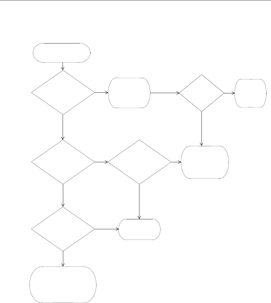
How a WX Switch Gets its Configuration 39
How a WX Switch
Gets its
Configuration
Figure 1 shows how a WX switch gets a configuration when you power it
on.
Figure 1 WX Switch Startup Algorithm
Switch is powered on.
Yes
No
No
Does switch have Is auto-config
a configuration?
Switch boots
Yes
Model WXR100?
Yes
No
Was factory reset
pressed during
No
Yes
Web Quick Start
power on?
Switch contacts
3WXM
to request
configuration.
Model WX1200
No
Yes
Boots with no configuration.
You must use the CLI to
start configuring the switch.
Yes
using its
configuration file. enabled?
Switch
is enabled.
displays
CLI prompt.
or WX2200?

Web Quick Start (WXR100, WX1200 and WX2200 Only) 40
Web Quick Start
(WXR100, WX1200
and WX2200 Only)
You can use the Web Quick Start to configure the switch to provide
wireless access to up to ten network users.
To access the Web Quick Start, attach a PC directly to port 1 or port 2 on
the switch and use a web browser on the PC to access IP address
192.168.100.1. (For more detailed instructions, see “Accessing the Web
Quick Start” on page 41.)
The Web Quick Start application is different from Web Manager. Web
Manager is a web-based management application that is available at any
time on a switch that already has IP connectivity. (Web Manager access
also requires the switch’s HTTPS server to be enabled.) The Web Quick
Start application is accessible only on unconfigured switches.
The Web Quick Start application is supported only on switch models
WXR100, WX1200, and WX2200. After you finish the Web Quick Start, it
will not be available again unless you clear (erase) the switch’s
configuration.
Web Quick Start
Parameters
The Web Quick Start enables you to configure basic wireless access for a small
office. You can use the Web Quick Start to configure the following parameters:
System name of the switch
Country code (the country where wireless access will be provided)
Administrator username and password
Management IP address and default router (gateway)
Time and date (statically configured or provided by an NTP server)
Management access
You can individually select Telnet, SSH, and Web View. You also can
secure the Console port. Access requires the administrator username
and password.
Power over Ethernet (PoE), for ports directly connected to MAPs
SSIDs and authentication types. The Web Quick Start enables you to
configure one secure SSID and one clear SSID. You can configure
additional SSIDs using the CLI or 3Com Wireless Switch Manager.
Usernames and passwords for your wireless users. You can configure
up to ten users with the Web Quick Start. To configure additional
users, use the CLI or 3Com Wireless Switch Manager.

Web Quick Start (WXR100, WX1200 and WX2200 Only) 41
Web Quick Start
Requirements
To use the Web Quick Start, you need the following:
AC power source for the switch
PC with an Ethernet port that you can connect directly to the switch
Category 5 (Cat 5) or higher Ethernet cable
If the PC is connected to the network, power down the PC or disable its
network interface card (NIC), then unplug the PC from the network.
You can use a Layer 2 device between the switch and the PC. However,
do not attach the switch to your network yet. The switch requires the PC
you attach to it for configuration to be in the 192.168.100.x subnet, and
uses the MSS DHCP server to assign the PC an address from this subnet. If
you attach the unconfigured switch to your network, the switch disables
the MSS DHCP server, if the switch detects another DHCP server on the
network. If the network does not have a DCHP server, the switch’s DHCP
server remains enabled and will offer IP addresses in the 192.168.100.x
subnet in response to DHCP Requests.
Accessing the Web
Quick Start
To access the Web Quick Start:
1Use a Category 5 (Cat 5) or higher Ethernet cable to connect the switch
directly to a PC that has a web browser.
2Connect the switch to an AC power source.
If the green power LED is lit, the switch is receiving power.
If you are configuring a WXR100, do not press the factory reset switch
during power on. Pressing this switch on an unconfigured switch causes
the switch to attempt to contact a 3Com Wireless Switch Manager server
instead of displaying the Web Quick Start. (Other switch models also have
reset switches, but the reset switch simply restarts these other models
without clearing the configuration.)
3Enable the PC’s NIC that is connected to the switch, if not already
enabled.
4Verify that the NIC is configured to use DHCP to obtain its IP address.
You will not be able to access the Web Quick Start if the IP address of the
NIC is statically configured.
5Use a web browser to access IP address 192.168.100.1.
42 CHAPTER 2: WX SETUP METHODS
This is a temporary, well-known address assigned to the unconfigured
switch when you power it on. The Web Quick Start enables you to
change this address.
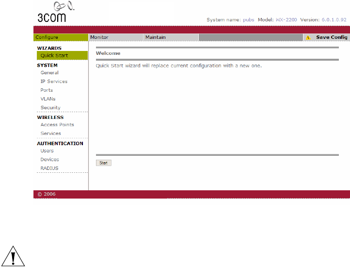
The first page of the Quick Start Wizard appears.
6Click Start to begin. The wizard screens guide you through the
configuration steps.
CAUTION: Use the wizard’s Next and Back buttons to navigate among
the wizard pages. Using the browser’s navigation buttons, such as Back
and Forward, can result in loss of information. Do not click the browser’s
Refresh or Reload button at any time while using the wizard. If you do
click Refresh or Reload, all the information you have entered in the
wizard will be cleared.
7After guiding you through the configuration, the wizard displays a
summary of the configuration values you selected.
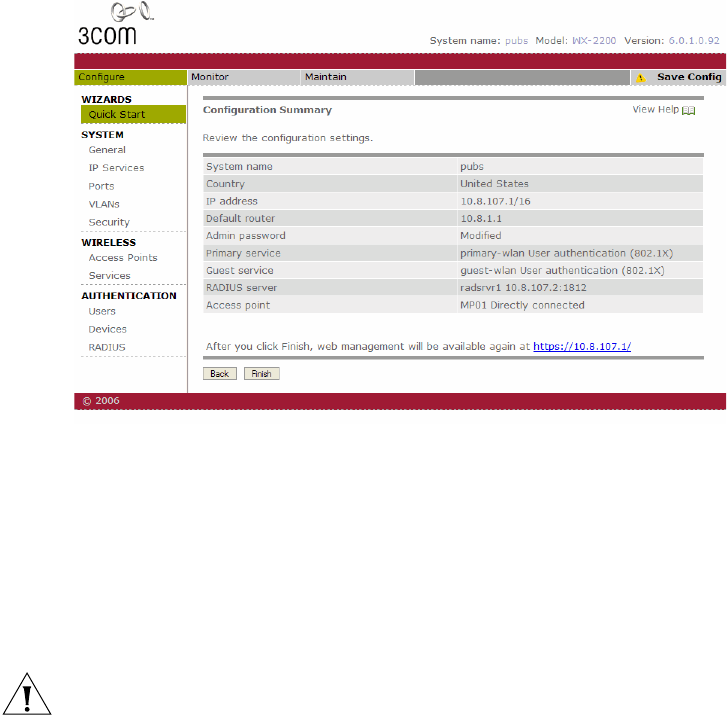
Web Quick Start (WXR100, WX1200 and WX2200 Only) 43
Here is an example:
8Review the configuration settings, then click Finish to save the changes
or click Back to change settings. If you want to quit for now and start
over later, click Cancel.
If you click Finish, the wizard saves the configuration settings into the
switch’s configuration file. If the switch is rebooted, the configuration
settings are restored when the reboot is finished.
The switch is ready for operation. You do not need to restart the switch.
CAUTION: On a WXR100, do not press the factory reset switch for
more than four seconds! On a WXR100 that is fully booted, the factory
reset switch erases the configuration if held for five seconds or more. If
you do accidentally erase the configuration, you can use the Web Quick
Start to reconfigure the switch.

44 CHAPTER 2: WX SETUP METHODS
CLI quickstart
Command
The quickstart command runs a script that interactively helps you
configure the following items:
System name
Country code (regulatory domain)
System IP address
Default route
802.1Q tagging for ports in the default VLAN
Administrative users and passwords
Enable password
System time, date, and timezone
Unencrypted (clear) SSID names
Usernames and passwords for guest access using WebAAA
Encrypted (crypto) SSID names and dynamic WEP encryption for
encrypted SSIDs’ wireless traffic
Usernames and passwords for secure access using 802.1X
authentication using PEAP-MSCHAP-V2 and secure wireless data
encryption using dynamic Wired Equivalent Privacy (WEP)
Directly connected MAPs
Distributed MAPs
The quickstart command displays a prompt for each of these items, and
lists the default if applicable. You can advance to the next item, and
accept the default if applicable, by pressing Enter.
The command also automatically generates a key pair for SSH.
Depending on your input, the command also automatically generates the
following key pairs and self-signed certificates:
SSH key pair (always generated)
Admin key pair and self-signed certificate (always generated)
EAP (802.1X) key pair and self-signed certificate (generated if you type
usernames and passwords for users of encrypted SSIDs)
WebAAA key pair and self-signed certificate (generated if you type
usernames and passwords for users of unencrypted SSIDs)

CLI quickstart Command 45
The command automatically places all ports that are not used for directly
connected MAPs into the default VLAN (VLAN 1).
The quickstart command prompts you for an administrative username
and password for managing the switch over the network. The command
automatically configures the same password as the switch’s enable
password. You can change the enable password later using the
set enablepass command.
CAUTION: The quickstart command is for configuration of a new switch
only. After prompting you for verification, the command erases the
switch’s configuration before continuing. If you run this command on a
switch that already has a configuration, the configuration will be erased.
In addition, error messages such as Critical AP Notice for directly
connected MAPs can appear.
To run the quickstart command:
1Attach a PC to the WX switch’s serial console port. (Use these modem
settings: 9600 bps, 8 bits, 1 stop, no parity, hardware flow control
disabled.)
2Press Enter three times, to display a username prompt (Username:), a
password prompt (Password:), and then a command prompt such as the
following:
WX1200-aabbcc>
(Each switch has a unique system name that contains the model number
and the last half of the switch’s MAC address.)
3Access the enabled level (the configuration level) of the CLI:
WX12000-aabbcc> enable
4Press Enter at the Enter password prompt.
5Type quickstart. The command asks you a series of questions. You can
type ? for more help. To quit, press Ctrl+C.
One of the questions the script asks is the country code. For a list of valid
country codes, see “Specifying the Country of Operation” on page 213.
Another question the script asks is, “Do you wish to configure wireless?”
If you answer y, the script goes on to ask you for SSID and user
information, for unencrypted and encrypted SSIDs. If you answer n, the
script generates key pairs for SSH and the administrative users you
entered, generates a self-signed administrative certificate, and then ends.

46 CHAPTER 2: WX SETUP METHODS
Quickstart Example This example configures the following parameters:
System name: WX1200-Corp
Country code (regulatory domain): US
System IP address: 172.16.0.21, on IP interface 172.16.0.21
255.255.255.0
The quickstart script asks for an IP address and subnet mask for the
system IP address, and converts the input into an IP interface with a
subnet mask, and a system IP address that uses that interface. Likewise, if
you configure this information manually instead of using the quickstart
command, you must configure the interface and system IP address
separately.
Default route: 172.16.0.20
Administrative user wxadmin, with password letmein. The only
management access the switch allows by default is CLI access through
the serial connection.
System Time and date parameters:
Date: 31st of March, 2007
Time: 4:36 PM
Timezone: PST (Pacific Standard Time), with an offset of -8 hours
from Universal Coordinated Time (UTC)
Unencrypted SSID name: public
Username user1 and password pass1 for WebAAA
Encrypted SSID name: corporate
Username bob and password bobpass for 802.1X authentication
Directly connected MAPs on port 2, model AP2750
The IP addresses, usernames, and passwords in this document are
examples. Use values that are appropriate for your organization.
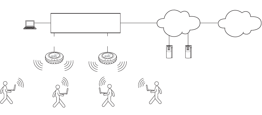
CLI quickstart Command 47
If you configure time and date parameters, you will be required to enter a
name for the timezone, and then enter the value of the timezone (the
offset from UTC) separately. You can use a string of up to 32 alphabetic
characters as the timezone name.
Figure 2 shows an example. Users bob and alice can access encrypted
SSID corporate on either of the MAPs. Users user1 and user2 can use the
same MAPs to access unencrypted SSID public. Although the same
hardware supports both SSIDs and sets of users, AAA ensures that only
the users who are authorized to access an SSID can access that SSID.
Users of separate SSIDs can even be in the same VLAN, as they are in this
example.
Figure 2 Single-Switch Deployment
WXR100-aabbcc# quickstart
This will erase any existing config. Continue? [n]: y
Answer the following questions. Enter '?' for help. ^C to
break out
System Name [WXR100]: WXR100-mrktg
Country Code [US]: US
System IP address []: 172.16.0.21
System IP address netmask []: 255.255.255.0
Default route []: 172.16.0.21
Do you need to use 802.1Q tagged default VLAN [Y/N]? Y: y
Specify the port number that needs to be tagged [1-2, <CR>
ends config]: 2
Specify the tagged value for port [2] [<CR> ends config:] 100
10.10.10.4
Port
3
WX1200-20-Corp
Port
2
Backbone
alice
Console
Internet
Corporate resources
user1 bob
user2
48 CHAPTER 2: WX SETUP METHODS
Specify the port number that needs to be tagged [1-2, <CR>
ends config]:
Admin username [admin]: wxadmin
Admin password [optional]: letmein
Enable password [optional]: enable
Do you wish to set the time? [y]: y
Enter the date (dd/mm/yy) []: 31/03/07
Is daylight saving time (DST) in effect [n]: n
Enter the time (hh:mm:ss) []: 04:36:20
Enter the timezone []: PST
Enter the offset (without DST) from GMT for 'PST' in hh:mm
[0:0]: -8:0
Do you wish to configure wireless? [y]: y
Enter a clear SSID to use: public
Do you want Web Portal authentication? [y]: y
Enter a username with which to do Web Portal, <cr> to exit:
user1
Enter a password for user1: user1pass1
Enter a username with which to do Web Portal, <cr> to exit:
Do you want to do 802.1x and PEAP-MSCHAPv2? [y]: y
Enter a crypto SSID to use: corporate
Enter a username with which to do PEAP-MSCHAPv2, <cr> to
exit: bob
Enter a password for bob: bobpass
Enter a username with which to do PEAP-MSCHAPv2, <cr> to exit:
Do you wish to configure access points? [y]: y
Enter a port number [1-2] on which an AP resides, <cr> to
exit: 2
Enter AP model on port 2: ap3750
Enter a port number [1-2] on which an AP resides, <cr> to exit:
Do you wish to configure distributed access points? [y]: y
Enter a DAP serial number, <cr> to exit: 0422700351
Enter model of DAP with S/N 0422700351: ap3750
Enter a DAP serial number, <cr> to exit:
success: created keypair for ssh
success: Type “save config” to save the configuration
WXR100-aabbcc# save config
6Optionally, enable Telnet and enable the admin user to use Telnet.
WXR100-aabbcc# set ip telnet server enable
WXR100-aabbcc# set user wxadmin attr service-type 6
7Verify the configuration changes.
WXR100-aabbcc# display config

Remote WX Configuration 49
8Save the configuration changes.
WXR100-aabbcc# save config
Remote WX
Configuration
You can use 3Com Wireless Switch Manager Services running in your
corporate network to configure WX switches in remote offices. The
following remote configuration scenarios are supported:
Drop ship—3Com Wireless Switch Manager Services running in the
corporate network can configure a WXR100 switch shipped directly to
a remote office. This option does not require any preconfiguration of
the switch.
Staged—You can stage any model of switch by preconfiguring IP
connectivity and enabling auto-config, then sending the switch to the
remote office. The switch contacts 3Com Wireless Switch Manager
Services in the corporate network to complete its configuration.
The drop ship option is supported only for the WXR100. The staged
option is supported for all switch models. Both options require 3Com
Wireless Switch Manager Services.
(For more information, see the “Configuring WX Switches Remotely”
chapter in the Wireless Switch Manager Reference Manual.
Opening the
QuickStart
Network Plan in
3Com Wireless
Switch Manager
3Com Wireless Switch Manager comes with two sample network plans:
QuickStart—Contains a two-floor building with two WX switches and
two MAPs on each switch. Each switch and its MAPs provide coverage
for a floor. The 3Com equipment is configured to provide both clear
(unencrypted) and secure (802.1X) wireless access.
StarterKit—Contains a simple rectangle as a floor plan, but with one
WX switch and four MAPs. You can modify this plan to deploy the
3Com starter kit (STR-B-xx).
The QuickStart network plan contains a configuration similar to the one
created by the CLI quickstart example in “Quickstart Example” on
page 46. The plan differs from the sample configuration by using
separate VLANs for WX management traffic, corporate users, and guest
users. Otherwise, the configuration is the same.
50 CHAPTER 2: WX SETUP METHODS
To open the network plan:
1Install 3WXM, if not already installed. (See the “Getting Started” chapter
of the Wireless Switch Manager User’s Guide or the “Installing 3WXM”
chapter of the Wireless Switch Manager Reference Manual.)
2Start 3WXM by doing one of the following:
On Windows systems, select Start > Programs > 3Com > 3WXM
> 3WXM, or double-click the 3WXM icon on the desktop.
On Linux systems, change directories to
3WXM_installation_directory/bin, and enter ./3wxm.
If you are starting 3Com Wireless Switch Manager for the first time, or
you have not entered license information previously, the License
Information dialog box appears. Enter the serial number and License,
then click OK.
3When the 3Com Wireless Switch Manager Services Connection dialog
appears, enter the IP address and UDP port of 3Com Wireless Switch
Manager Services (if installed on a different machine than the client), and
click Next.
4If the Certificate Check dialog appears, click Accept to complete the
connection to 3Com Wireless Switch Manager Services.
5Select File > Switch Network Plan.
6Click Yes to close the plan that is currently open.
The Switch Network Plan dialog appears, listing the available network
plans.
7Select QuickStart and click Next.

3CONFIGURING AAA FOR
ADMINISTRATIVE AND LOCAL
ACCESS
3Com Mobility System Software (MSS) supports authentication,
authorization, and accounting (AAA) for secure network connections. As
administrator, you must establish administrative access for yourself and
optionally other local users before you can configure the WX for
operation.
Overview Here is an overview of configuration topics:
1 Console connection. By default, any administrator can connect to the
console port and manage the switch, because no authentication is
enforced. (3Com recommends that you enforce authentication on the
console port after initial connection.)
2 Telnet or SSH connection. Administrators cannot establish a Telnet or
Secure Shell (SSH) connection to the WX by default. To provide Telnet or
SSH access, you must add a username and password entry to the local
database or, optionally, set the authentication method for Telnet users to
a Remote Authentication Dial-In User Service (RADIUS) server.
A CLI Telnet connection to the WX is not secure, unlike SSH, 3WXM and
Web Manager connections. (For details, see Chapter 20, “Managing Keys
and Certificates,” on page 413.)
3 Restricted mode. When you initially connect to the WX, your mode of
operation is restricted. In this mode, only a small subset of status and
monitoring commands is available. Restricted mode is useful for
administrators with basic monitoring privileges who are not allowed to
change the configuration or run traces.
4 Enabled mode. To enter the enabled mode of operation, you type the
enable command at the command prompt. In enabled mode, you can
use all CLI commands. Although MSS does not require an enable
password, 3Com highly recommends that you set one.
52 CHAPTER 3: CONFIGURING AAA FOR ADMINISTRATIVE AND LOCAL ACCESS
5 Customized authentication. You can require authentication for all
users or for only a subset of users. Username globbing (see “User Globs,
MAC Address Globs, and VLAN Globs” on page 30) allows different
users or classes of user to be given different authentication treatments.
You can configure console authentication and Telnet authentication
separately, and you can apply different authentication methods to each.
For any user, authorization uses the same method(s) as authentication for
that user.
6 Local override. A special authentication technique called local override
lets you attempt authentication via the local database before attempting
authentication via a RADIUS server. The WX switch attempts
administrative authentication in the local database first. If it finds no
match, the WX attempts administrative authentication on the RADIUS
server. (For information about setting a WX switch to use RADIUS servers,
see Chapter 22, “Configuring Communication with RADIUS,” on
page 519.)
7 Accounting for administrative access sessions. Accounting records
can be stored and displayed locally or sent to a RADIUS server.
Accounting records provide an audit trail of the time an administrative
user logged in, the administrator’s username, the number of bytes
transferred, and the time the session started and ended.
Figure 3 illustrates a typical WX switch, MAPs, and network administrator
in an enterprise network. As network administrator, you initially access
the WX switch via the console. You can then optionally configure
authentication, authorization, and accounting for administrative access
mode.
3Com recommends enforcing authentication for administrative access
using usernames and passwords stored either locally or on RADIUS
servers.
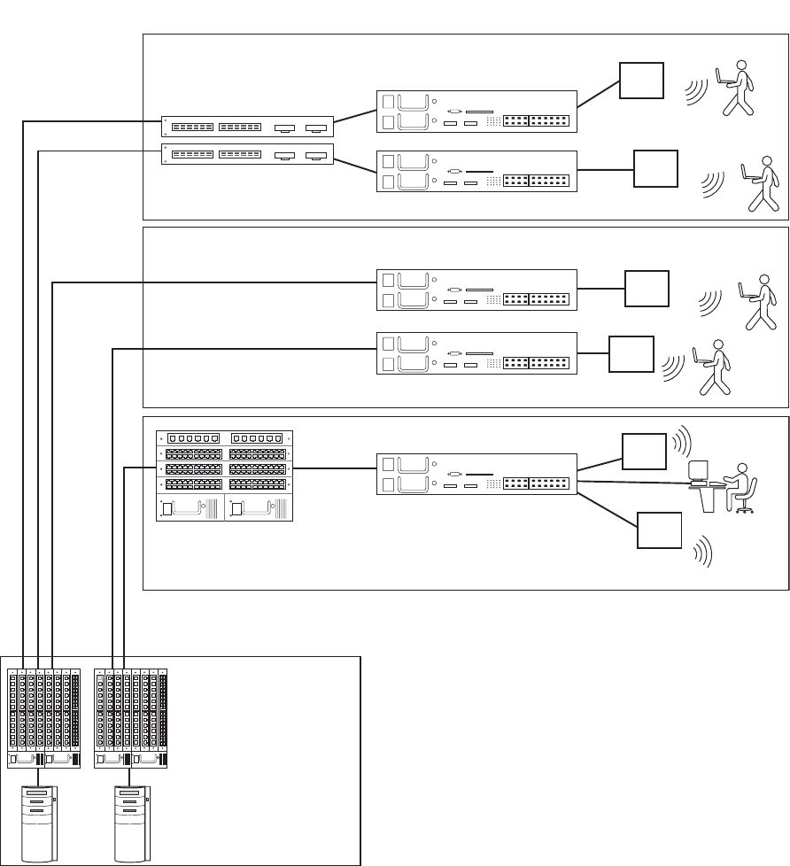
Overview 53
Figure 3 Typical 3Com Mobility System
WX switch
Core router
Layer 2 switches
WX switches
B
uilding
1
D
a
t
a
ce
n
t
e
r
F
loo
r
3
F
loo
r
2
Layer 2 or Layer 3 switches
RADIUS or AAA
Servers
F
loo
r
1
WX switches
MAP
MAP
MAP
MAP
MAP
MAP

54 CHAPTER 3: CONFIGURING AAA FOR ADMINISTRATIVE AND LOCAL ACCESS
Before You Start Before reading more of this chapter, read the Wireless LAN Switch and
Controller Quick Start Guide to set up a WX switch and the attached
MAPs for basic service.
About
Administrative
Access
The authentication, authorization, and accounting (AAA) framework helps
secure network connections by identifying who the user is, what the user
can access, and the amount of network resources the user can consume.
Access Modes MSS provides AAA either locally or via remote servers to authenticate
valid users. MSS provides two modes of access:
Administrative access mode — Allows a network administrator to
access the WX switch and configure it.
You must establish administrative access in enabled mode before
adding users. See “Enabling an Administrator” on page 55.
Network access mode — Allows network users to connect through
the WX switch. For information about configuring network users, see
Chapter 21, “Configuring AAA for Network Users,” on page 433.
Types of
Administrative Access
MSS allows you access to the WX switch with the following types of
administrative access:
Console — Access via only the console port. For more information,
see “First-Time Configuration via the Console” on page 55.
Te ln et — Users who access MSS via the Telnet protocol. For information
about setting up a WX switch for Telnet access, see Chapter 6,
“Configuring and Managing IP Interfaces and Services,” on page 103.
Secure Shell (SSH) — Users who access MSS via the SSH protocol. For
information about setting up a WX switch for SSH access, see Chapter 6,
“Configuring and Managing IP Interfaces and Services,” on page 103.
3WXM — After you configure the WX switch as described in this
guide, you can further configure the WX switch using the 3WXM tool
suite. For more information, see the Wireless Switch Manager
Reference Manual.
Web View — A Web-based application for configuring and
managing a single WX switch through a Web browser. Web View
uses a secure connection via Hypertext Transfer Protocol over Secure
Sockets Layer (HTTPS).

First-Time Configuration via the Console 55
First-Time
Configuration via
the Console
Administrators must initially configure the WX switch with a computer or
terminal connected to the WX console port through a serial cable. Telnet
access is not initially enabled.
To configure a previously unconfigured WX switch via the console, you
must complete the following tasks:
Enable an administrator. (See “Enabling an Administrator” on
page 55.)
Configure authentication. (See “Authenticating at the Console” on
page 57.)
Optionally, configure accounting. (see “Configuring Accounting for
Administrative Users” on page 59.)
Save the configuration. (See “Saving the Configuration” on page 61.)
Enabling an
Administrator
To enable yourself as an administrator, you must log in to the WX switch
from the console. Until you set the enable password and configure
authentication, the default username and password are blank. Press Enter
when prompted for them.
To enable an administrator:
1Log in to the WX switch from the serial console, and press Enter when
the WX switch displays a username prompt:
Username:
2Press Enter when the WX switch displays a password prompt.
Password:
3Type enable to go into enabled mode.
WX1200> enable
4Press Enter to display an enabled-mode command prompt:
WX1200#
Once you see this prompt after you have typed the enable command,
you have administrative privileges, which allow you to further configure
the WX switch.

56 CHAPTER 3: CONFIGURING AAA FOR ADMINISTRATIVE AND LOCAL ACCESS
Setting the WX
Switch Enable
Password
There is one enable password for the entire WX switch. You can
optionally change the enable password from the default.
3Com recommends that you change the enable password from the
default (no password) to prevent unauthorized users from entering
configuration commands.
Setting the WX Enable Password for the First Time
To set the enable password for the first time:
1At the enabled prompt, type set enablepass.
2At the “Enter old password” prompt, press Enter.
3At the “Enter new password” prompt, enter an enable password of up to
32 alphanumeric characters with no spaces. The password is not
displayed as you type it.
The enable password is case-sensitive.
4Type the password again to confirm it.
MSS lets you know the password is set.
WX1200# set enablepass
Enter old password:
Enter new password:
Retype new password:
Password changed
Be sure to use a password that you will remember. If you lose the enable
password, the only way to restore it causes the system to return to its
default settings and wipes out any saved configuration. (For details, see
“Recovering the System When the Enable Password is Lost” on
page 622.)
5Store the configuration into nonvolatile memory by typing the following
command:
WX1200# save config
success: configuration saved.

First-Time Configuration via the Console 57
3WXM Enable Password
If you use 3WXM to continue configuring the switch, you will need to
enter the switch’s enable password when you upload the switch’s
configuration into 3WXM. (For 3WXM information, see the Wireless
Switch Manager Reference Manual.)
Authenticating at the
Console
You can configure the console so that authentication is required, or so
that no authentication is required. 3Com recommends that you enforce
authentication on the console port.
To enforce console authentication, take the following steps:
1Add a user in the local database by typing the following command with a
username and password:
WX1200# set user username password password
success: change accepted.
2To enforce the use of console authentication via the local database, type
the following command:
If you type this command before you have created a local username and
password, you can lock yourself out of the WX switch. Before entering
this command, you must configure a local username and password.
WX1200# set authentication console * local
3To store this configuration into nonvolatile memory, type the following
command:
WX1200# save config
success: configuration saved.
By default, no authentication is required at the console. If you have
previously required authentication and have decided not to require it
(during testing, for example), type the following command to configure
the console so that it does not require username and password
authentication:
WX1200# set authentication console * none

58 CHAPTER 3: CONFIGURING AAA FOR ADMINISTRATIVE AND LOCAL ACCESS
The authentication method none you can specify for administrative
access is different from the fallthru authentication type None, which
applies only to network access. The authentication method none allows
access to the WX switch by an administrator. The fallthru authentication
type None denies access to a network user. (For information about the
fallthru authentication types, see “Authentication Algorithm” on
page 435.)
Customizing AAA
with “Globs” and
Groups
“Globbing” lets you classify users by username or media access control
(MAC) address for different AAA treatments. A user glob is a string,
possibly containing wildcards, for matching AAA and IEEE 802.1X
authentication methods to a user or set of users. The WX switch supports
the following wildcard characters for user globs:
Single asterisk (*) matches the characters in a username up to but not
including a separator character, which can be an at (@) sign or a
period (.).
Double asterisk (**) matches all usernames.
In a similar fashion, MAC address globs match authentication methods to
a MAC address or set of MAC addresses. For details, see “User Globs,
MAC Address Globs, and VLAN Globs” on page 30.
A user group is a named collection of users or MAC addresses sharing a
common authorization policy. For example, you might group all users on
the first floor of building 17 into the group bldg-17-1st-floor, or group all
users in the IT group into the group infotech-people. Individual user
entries override group entries if they both configure the same attribute.
(For information about configuring users and user groups, see “Adding
and Clearing Local Users for Administrative Access” on page 59.)
Setting User
Passwords
Like usernames, passwords are case-sensitive. To make passwords secure,
make sure they contain uppercase and lowercase letters and numbers. 3Com
recommends that all users create passwords that are memorable to
themselves, difficult for others to guess, and not subject to a dictionary attack.
User passwords are automatically encrypted when entered in the local
database. However, the encryption is not strong. It is designed only to
discourage someone looking over your shoulder from memorizing your
password as you display the configuration. To maintain security, MSS
displays only the encrypted form of the password in display commands.

Configuring Accounting for Administrative Users 59
Although MSS allows you to configure a user password for the special
“last-resort” guest user, the password has no effect. Last-resort users can
never access a WX in administrative mode and never require a password.
Adding and Clearing
Local Users for
Administrative Access
Usernames and passwords can be stored locally on the WX switch. 3Com
recommends that you enforce console authentication after the initial
configuration to prevent anyone with unauthorized access to the console
from logging in. The local database on the WX switch is the simplest way
to store user information in a 3Com system.
To configure a user in the local database, type the following command:
set user username password [encrypted] password
For example, to configure user Jose with the password spRin9 in the local
database on the WX switch, type the following command:
WX1200# set user Jose password spRin9
success: User Jose created
To clear a user from the local database, type the following command:
clear user username
Configuring
Accounting for
Administrative
Users
Accounting allows you to track network resources. Accounting records
can be updated for three important events: when the user is first
connected, when the user roams from one MAP to another, and when
the user terminates his or her session. The default for accounting is off.
To configure accounting for administrative logins, use the following
command:
set accounting {admin | console} {user-glob}
{start-stop |stop-only} method1 [method2] [method3]
[method4]
set accounting {admin | console} {user-glob}
{start-stop |stop-only} method1 [method2] [method3]
[method4]
To configure accounting for administrative logins over the network at
EXAMPLE, enter the following command:
set accounting admin EXAMPLE\*
{start-stop | stop-only} aaa-method
60 CHAPTER 3: CONFIGURING AAA FOR ADMINISTRATIVE AND LOCAL ACCESS
You can select either start-stop or stop-only accounting modes. The
stop-only mode sends only stop records, whereas start-stop sends both
start and stop records, effectively doubling the number of accounting
records. In most cases, stop-only is entirely adequate for administrative
accounting, because a stop record contains all the information you might
need about a session.
In the set accounting command, you must include AAA methods that
specify whether to use the local database or RADIUS server to receive the
accounting records. Specify local, which causes the processing to be
done on the WX switch, or specify a RADIUS server group. For
information about configuring a RADIUS server group, see “Configuring
RADIUS Server Groups” on page 524.
For example, you can set accounting for administrative users using the
start-stop mode via the local database:
WX1200# set accounting admin EXAMPLE\* start-stop local
success: change accepted.
The accounting records show the date and time of activity, the user’s
status and name, and other attributes. The display accounting
statistics command displays accounting records for administrative users
after they have logged in to the WX switch.
(For information about network user accounting, see “Configuring
Accounting for Wireless Network Users” on page 504. For information
and an output example for the display accounting statistics command,
see the Wireless LAN Switch and Controller Command Reference.)

Displaying the AAA Configuration 61
Displaying the AAA
Configuration
To display your AAA configuration, type the following command:
WX1200# display aaa
Default Values
authport=1812 acctport=1813 timeout=5 acct-timeout=5
retrans=3 deadtime=0 key=(null) author-pass=(null)
Radius Servers
Server Addr Ports T/o Tries Dead State
-------------------------------------------------------------------
r1 192.168.253.1 1812 1813 5 3 0 UP
Server groups
sg1: r1
set authentication console * local
set authentication admin * local
set accounting admin Geetha stop-only local
set accounting admin * start-stop local
user Geetha
Password = 1214253d1d19 (encrypted)
(For information about the fields in the output, see the Wireless LAN
Switch and Controller Command Reference.)
Saving the
Configuration
You must save the configuration for all commands that you enter and
want to use for future sessions. After you enter the administrator’s AAA
configuration, type the following command to maintain these commands
in WX nonvolatile memory:
WX1200# save config
success: configuration saved.
You can also specify a filename for the configuration—for example,
configday. To do this, type the following command:
WX1200# save config configday
Configuration saved to configday.
You must type the save config command to save all configuration
changes since the last time you rebooted the WX switch or saved the
configuration. If the WX switch is rebooted before you have saved the
configuration, all changes are lost.
You can also type the load config command, which reloads the WX switch
to the last saved configuration or loads a particular configuration filename.
(For more information, see “Managing Configuration Files” on page 609.)

62 CHAPTER 3: CONFIGURING AAA FOR ADMINISTRATIVE AND LOCAL ACCESS
Administrative AAA
Configuration
Scenarios
The following scenarios illustrate typical configurations for administrative
and local authentication. For all scenarios, the administrator is Natasha
with the password m@Jor. (For RADIUS server configuration details, see
Chapter 22, “Configuring Communication with RADIUS,” on page 519.)
“Local Authentication” on page 62
“Local Authentication for Console Users and RADIUS Authentication
for Telnet Users” on page 62
“Local Override and Backup Local Authentication” on page 64
“Authentication When RADIUS Servers Do Not Respond” on page 63
Local Authentication The first time you access a WX switch, it requires no authentication. (For
more information, see “First-Time Configuration via the Console” on
page 55.) In this scenario, after the initial configuration of the WX switch,
Natasha is connected through the console and has enabled access.
To enable local authentication for a console user, you must configure a
local username. Natasha types the following commands in this order:
WX1200# set user natasha password m@Jor
User natasha created
WX1200# set authentication console * local
success: change accepted.
WX1200# save config
success: configuration saved.
Local Authentication
for Console Users and
RADIUS
Authentication for
Telnet Users
This scenario illustrates how to enable local authentication for console
users and RADIUS authentication for Telnet administrative users. To do so,
you configure at least one local username for console authentication and
set up a RADIUS server for Telnet administrators. Natasha types the
following commands in this order:
WX1200# set user natasha password m@Jor
User natasha created
WX1200# set authentication console * local
success: change accepted.
WX1200# set radius server r1 address 192.168.253.1 key sunFLOW#$
success: change accepted.

Administrative AAA Configuration Scenarios 63
Natasha also adds the RADIUS server (r1) to the RADIUS server group sg1,
and configures Telnet administrative users for authentication through the
group. She types the following commands in this order:
WX1200# set server group sg1 members r1
success: change accepted.
WX1200# set user admin attr service-type 6
success: change accepted.
WX1200# set authentication admin * sg1
success: change accepted.
WX1200# save config
success: configuration saved.
If the service-type is not set to 6 (Administrative), the user will not be able
to enter “enable” mode commands.
Authentication When
RADIUS Servers Do
Not Respond
This scenario illustrates how to enable RADIUS authentication for both
console and administrative users, but to unconditionally allow access for
administrative and console users if the RADIUS server (in this case, server
r1 in server group sg1) does not respond. To configure unconditional
authentication, Natasha sets the authentication method to none. She
types the following commands in this order:
WX1200# set user natasha password m@Jor
User natasha created
WX1200# set radius server r1 address 192.168.253.1 key
sunFLOW#$
success: change accepted.
WX1200# set server group sg1 members r1
success: change accepted.
WX1200# set authentication console * sg1 none
success: change accepted.
WX1200# set user admin attr service-type 6
success: change accepted.
WX1200# set authentication admin * sg1 none
success: change accepted.
WX1200# save config
success: configuration saved.
64 CHAPTER 3: CONFIGURING AAA FOR ADMINISTRATIVE AND LOCAL ACCESS
Local Override and
Backup Local
Authentication
This scenario illustrates how to enable local override authentication for
console users. Local override means that MSS attempts authentication
first via the local database. If it finds no match for the user in the local
database, MSS then tries a RADIUS server—in this case, server r1 in server
group sg1. Natasha types the following commands in this order:
WX1200# set user natasha password m@Jor
User natasha created
WX1200# set radius server r1 address 192.168.253.1 key sunFLOW#$
success: change accepted.
WX1200# set server group sg1 members r1
success: change accepted.
WX1200# set authentication console * local sg1
success: change accepted.
WX1200# save config
success: configuration saved.
Natasha also enables backup RADIUS authentication for Telnet
administrative users. If the RADIUS server does not respond, the user is
authenticated by the local database in the WX switch. Natasha types the
following commands:
WX1200# set authentication admin * sg1 local
success: change accepted.
WX1200# save config
success: configuration saved.
The order in which Natasha enters authentication methods in the set
authentication command determines the method MSS attempts first.
The local database is the first method attempted for console users and
the last method attempted for Telnet administrators.

4MANAGING USER PASSWORDS
This chapter describes how to manage user passwords, configure user
passwords, and how to display password information.
Overview 3COM recommends that all users create passwords that are memorable
to themselves, difficult for others to guess, and not subject to a
dictionary attack.
By default, user passwords are automatically encrypted when entered in
the local database. However, the encryption is not strong. It is designed
only to discourage someone looking over your shoulder from memorizing
your password as you display the configuration. To maintain security, MSS
displays only the encrypted form of the password in display commands.
Optionally, you can configure MSS so that the following additional
restrictions apply to user passwords:
Passwords must be a minimum of 10 characters in length, and a
mix of uppercase letters, lowercase letters, numbers, and special
characters, including at least two of each (for example, Tre%Pag32!).
A user cannot reuse any of his or her 10 previous passwords (not
applicable to network users).
When a user changes his or her password, at least 4 characters
must be different from the previous password.
A user password expires after a configurable amount of time.
A user is locked out of the system after a configurable number of
failed login attempts. When this happens, a trap is generated and an
alert is logged.
(Administrative users can gain access to the system through the
console even when the account is locked.)

66 CHAPTER 4: MANAGING USER PASSWORDS
Only one unsuccessful login attempt is allowed in a 10-second
period for a user or session.
All administrative logins, logouts, logouts due to idle timeout, and
disconnects are logged.
The audit log file on the WX switch (command_audit.cur) cannot
be deleted, and attempts to delete log files are recorded.
These restrictions are disabled by default.
Configuring
Passwords
This section describes the following tasks:
Setting a password for a user in the local database
Enabling restrictions on password usage
Setting the maximum number of failed login attempts for a user
Specifying the minimum allowable password length
Setting the length of time before password expiration
Restoring access to a user that has been locked out of the system
Setting Passwords for
Local Users
To configure a user’s password in the local database, type the following
command:
set user username password [encrypted] password
For example, to configure user Jose with the password spRin9 in the local
database on the WX, type the following command:
WX# set user Jose password spRin9
success: User Jose created
The encrypted option indicates that the password string you are
entering is the encrypted form of the password. Use this option only if
you do not want MSS to encrypt the password for you.
By default, usernames and passwords in the local database are not
case-sensitive; passwords can be made case-sensitive by activating
password restrictions, as described in the following section.
To clear a user from the local database, type the following command:
clear user username
Configuring Passwords 67
Enabling Password
Restrictions
To activate password restrictions for network and administrative users,
use the following command:
set authentication password-restrict {enable | disable}
When this command is enabled, the following password restrictions take
effect:
Passwords must be a minimum of 10 characters in length, and a
mix of uppercase letters, lowercase letters, numbers, and special
characters, including at least two of each (for example, Tre%Pag32!).
A user cannot reuse any of his or her 10 previous passwords (not
applicable to network users).
When a user changes his or her password, at least 4 characters
must be different from the previous password.
The password restrictions are disabled by default. When you enable
them, MSS evaluates the passwords configured on the WX and
displays a list of users whose password does not meet the restriction
on length and character types.
For example, to enable password restrictions on the WX switch, type the
following command:
WX# set authentication password-restrict enable
warning: the following users have passwords that do not have
at least 2 each of upper-case letters, lower-case letters,
numbers and special characters -
dan
admin
user1
user2
goofball
dang
success: change accepted.
Setting the Maximum
Number of Login
Attempts
To specify the maximum number of login attempts users can make before
being locked out of the system, use the following command:
set authentication max-attempts number
For Telnet or SSH sessions, a maximum of 4 failed login attempts are
allowed by default. For console or network sessions, an unlimited number
of failed login attempts are allowed by default.
68 CHAPTER 4: MANAGING USER PASSWORDS
You can specify a number between 0 – 2147483647. Specifying 0 causes
the number of allowable login attempts to reset to the default values.
If a user is locked out of the system, you can restore the user’s access with
the clear user lockout command. (See “Restoring Access to a
Locked-Out User” on page 70.)
For example, to allow users a maximum of 3 attempts to log into the
system, type the following command:
WX# set authentication max-attempts 3
success: change accepted.
Specifying Minimum
Password Length
To specify the minimum allowable length for user passwords, use the
following command:
set authentication minimum-password-length length
You can specify a minimum password length between 0 ñ 32 characters.
Specifying 0 removes the restriction on password length. By default, there
is no minimum length for user passwords. When this command is
configured, you cannot configure a password shorter than the specified
length.
When you enable this command, MSS evaluates the passwords
configured on the WX switch and displays a list of users whose password
does not meet the minimum length restriction.
For example, to set the minimum length for user passwords at 7
characters, type the following command:
WX# set authentication minimum-password-length 7
warning: the following users have passwords that are shorter
than the minimum password length -
dan
admin
user2
goofball
success: change accepted.
Configuring Passwords 69
Configuring
Password Expiration
Time
To specify how long a user’s password is valid before it must be reset, use
the following command:
set user username expire-password-in time
To specify how long the passwords are valid for users in a user group, use
the following command:
set usergroup group-name expire-password-in time
By default, user passwords do not expire. You can use this command to
specify how long a specified user’s password is valid. After this amount of
time, the user’s password expires, and a new password will have to be
set. The amount of time can be specified in days (for example, 30 or 30d),
hours (720h), or a combination of days and hours (30d12h)
For example, the following command sets user Student1ís password to
be valid for 30 days:
WX# set user Student1 expire-password-in 30
success: change accepted.
The following command sets user Student1ís password to be valid for 30
days and 15 hours:
WX# set user Student1 expire-password-in 30d15h
success: change accepted.
The following command sets user Student1’s password to be valid for
720 hours:
WX# set user Student1 expire-password-in 720h
success: change accepted.
The following command sets the passwords for the users in user group
cardiology to be valid for 30 days:
WX# set usergroup cardiology expire-password-in 30
success: change accepted.
70 CHAPTER 4: MANAGING USER PASSWORDS
Restoring Access to a
Locked-Out User
If a user’s password has expired, or the user is unable to log in within the
configured limit for login attempts, then the user is locked out of the
system, and cannot gain access without the intervention of an
administrator.
To restore access to a user who had been locked out of the system, use
the following command:
clear user username lockout
If a user has been locked out of the system because of an expired
password, you must first assign the user a new password before you can
restore access to the user.
The following command restores access to user Nin, who had previously
been locked out of the system:
WX# clear user Nin lockout
success: change accepted.
Displaying Password
Information
User password information can be displayed with the display aaa
command. For example:
WX# display aaa
...
...
set authentication password-restrict enable
set authentication minimum-password-length 10
...
user bob
Password = 00121a08015e1f (encrypted)
Password-expires-in = 59 hours (2 days 11 hours)
status = disabled
vlan-name = default
service-type = 7
(For details on displaying passwords, see the Wireless LAN Switch and
Controller Command Reference.

5CONFIGURING AND MANAGING
PORTS AND VLANS
This chapter describes how to configure and manage ports and VLANs.
Configuring and
Managing Ports
You can configure and display information for the following port
parameters:
Port type
Name
Speed and autonegotiation
Port state
Power over Ethernet (PoE) state
Load sharing
Setting the Port Type A WX switch port can be one of the following types:
Network port. A network port is a Layer 2 switch port that connects
the WX switch to other networking devices such as switches and
routers.
MAP access port. A MAP access port connects the WX switch to a
MAP. The port also can provide power to the MAP. Wireless users are
authenticated to the network through a MAP access port.
A Distributed MAP, which is connected to WX switches through
intermediate Layer 2 or Layer 3 networks, does not use a MAP access
port. To configure for a Distributed MAP, see “Configuring a MAP
Connection” on page 74 and Chapter 10, “Configuring MAP Access
Points,” on page 177.
Wired authentication port. A wired authentication port connects the
WX switch to user devices, such as workstations, that must be
authenticated to access the network.

72 CHAPTER 5: CONFIGURING AND MANAGING PORTS AND VLANS
All WX switch ports are network ports by default. You must set the port
type for ports directly connected to MAP access ports and to wired user
stations that must be authenticated to access the network. When you
change port type, MSS applies default settings appropriate for the port
type. Table 5 lists the default settings applied for each port type. For
example, the MAP column lists default settings that MSS applies when
you change a port type to ap (MAP).
Table 6 lists how many MAPs you can configure on a WX switch, and
how many MAPs a switch can boot. The numbers are for directly
connected and Distributed MAPs combined.
Table 5 Port Defaults Set by Port Type Change
Port Type
Parameter MAP Access Wired Authentication Network
VLAN
membership Removed from
all VLANs. You
cannot assign a
MAP access port
to a VLAN. MSS
automatically
assigns MAP
access ports to
VLANs based on
user traffic.
Removed from all VLANs.
You cannot assign a
wired authentication port
to a VLAN. MSS
automatically assigns
wired authentication
ports to VLANs based on
user traffic.
None
Note: If you clear a
port, MSS resets the
port as a network
port but does not
add the port back to
any VLANs. You
must explicitly add
the port to the
desired VLAN(s).
Spanning Tree
Protocol (STP) Not applicable Not applicable Based on the STP
states of the VLANs
the port is in.
802.1X Uses
authentication
parameters
configured for
users.
Uses authentication
parameters configured for
users.
No authentication.
Port groups Not applicable Not applicable None
IGMP snooping Enabled as users
are
authenticated
and join VLANs.
Enabled as users are
authenticated and join
VLANs.
Enabled as the port
is added to VLANs.
Maximum user
sessions Not applicable 1 (one) Not applicable

Configuring and Managing Ports 73
Setting a Port for a Directly Connected MAP
Before configuring a port as a MAP access port, you must use the set
system countrycode command to set the IEEE 802.11 country-specific
regulations on the WX switch. (See “Specifying the Country of
Operation” on page 213.)
Some MSS features that work with directly connected MAPs require a
port number to be specified. For this purpose, you can optionally specify
the port number attached to a directly connected MAP.
To set a port for a MAP, use the following command:
set port type ap port-list
model {2330 | 2330A | AP2750 | AP3150 | AP3750 | mp-52 |
mp-241 | mp-252 | mp-262 | mp-341 | mp-352 | mp-372 |
mp-372-CN | mp-372-JP | mp422 | mp620} poe {enable | disable}
[radiotype {11a | 11b | 11g}]
You must specify a port list of one or more port numbers, the MAP model
number, and the PoE state. (For details about port lists, see “Port Lists”
on page 32.)
MAP models AP2750, MP-241, and MP-341 have a single radio that can
be configured for 802.11b/g. Other MAP models have two radios. On
two-radio models, one radio is always 802.11a. The other radio is
802.11b/g, but can be configured for 802.11b or 802.11g exclusively. If
the country of operation specified by the set system countrycode
command does not allow 802.11g, the default is 802.11b.
Models MP-52, MP-241, MP-252, MP-262, MP-341, and MP-352 have
been discontinued but are still supported by the command.
Table 6 Maximum MAPs Supported Per Switch
WX Switch Model
Maximum
Configured Maximum Booted
WX4400 300 24, 48, 72, 96, or 120,
depending on the license.
WX2200 320 24, 48, 72, 96, or 120,
depending on the license.
WX1200 30 12
WXR100 8 3

74 CHAPTER 5: CONFIGURING AND MANAGING PORTS AND VLANS
You cannot configure any gigabit Ethernet port, or port 7 or 8 on a
WX1200 switch, or port 1 on a WXR100, as a MAP port. To manage a
MAP on a switch model that does not have 10/100 Ethernet ports,
configure a Distributed MAP connection on the switch. (See “Configuring
a MAP Connection” on page 74.)
The radio models in MP-620 require external antenna, and model
MP-262 requires an external antenna for the 802.11b/g radio. The
following models have internal antennas but also have connectors for
optional use of external antennas instead: AP2750, AP3150, AP3750,
AP7250, AP8250, AP8750, MP-372, MP-372-CN, and MP-372-JP.
(Antenna support on a specific model is limited to the antennas certified
for use with that model.) To specify the antenna model, use the set {ap |
dap} radio antennatype command.
To set ports 4 through 6 for MAP model AP2750 and enable PoE on the
ports, type the following command:
WX1200# set ap <apnum> port <port> model <ap_type> [ poe
<enable | disable> ]
This may affect the power applied on the configured ports.
Would you like to continue? (y/n) [n]y
success: change accepted.
Additional configuration is required to place a MAP into operation. For
information, see Chapter 10, “Configuring MAP Access Points,” on
page 177.
Configuring a MAP Connection
To configure a connection for a MAP (referred to as a AP in the CLI), use
the following command:
set ap apnumber serial-id serial-ID
model {2230 | 2230A | AP7250 | AP3150 | AP3750 | mp-52 |
mp-241 | mp-252 | mp-262 | mp-341 | mp-352 | mp-372 |
mp-372-CN | mp-422 | mp620} [radiotype {11a |11b|11g}]
The apnumber refers to an index value that identifies the MAP on the WX
switch. This value does not have to be related to the port to which the
MAP is connected.
The range of valid apnumber values depends on the WX model. Table 7
lists the ranges for each WX model.

Configuring and Managing Ports 75
For the serial-id parameter, specify the serial ID of the MAP. The serial ID
is listed on the MAP case. To display the serial ID using the CLI, use the
display version details command.
The model and radiotype parameters have the same options as they do
with the set port type ap command. Because the WX does not supply
power to an indirectly connected MAP, the set ap command does not
use the poe parameter.
To configure a connection for MAP 1, which is a MAP model MP-372
with serial-ID 0322199999, type the following command:
WX# set ap 1 serial-id 0322199999 model mp-372
success: change accepted.
Setting a Port for a Wired Authentication User
To set a port for a wired authentication user, use the following command:
set port type wired-auth port-list [tag tag-list]
[max-sessions num]
You must specify a port list. Optionally, you also can specify a tag-list to
subdivide the port into virtual ports, and set the maximum number of
simultaneous user sessions that can be active on the port. By default, one
user session can be active on the port at a time.
The fallthru authentication type is used if the user does not support
802.1X and is not authenticated by MAC authentication. The default is
none, which means the user is automatically denied access if neither
802.1X authentication or MAC authentication is successful.
To set port 17 as a wired authentication port, type the following
command:
WX1200# set port type wired-auth 7
success: change accepted
Table 7 Valid dap-num Values
Switch Model Valid Range
WX4400 1 to 300
WX1200 1 to 30
WXR100 1 to 8
WX2200 1 to 320

76 CHAPTER 5: CONFIGURING AND MANAGING PORTS AND VLANS
This command configures port 7 as a wired authentication port
supporting one interface and one simultaneous user session.
For 802.1X clients, wired authentication works only if the clients are
directly attached to the wired authentication port, or are attached
through a hub that does not block forwarding of packets from the client
to the PAE group address (01:80:c2:00:00:03). Wired authentication
works in accordance with the 802.1X specification, which prohibits a
client from sending traffic directly to an authenticator’s MAC address
until the client is authenticated. Instead of sending traffic to the
authenticator’s MAC address, the client sends packets to the PAE group
address. The 802.1X specification prohibits networking devices from
forwarding PAE group address packets, because this would make it
possible for multiple authenticators to acquire the same client.
For non-802.1X clients, who use MAC authentication, WebAAA, or
last-resort authentication, wired authentication works if the clients are
directly attached or indirectly attached.
If clients are connected to a wired authentication port through a
downstream third-party switch, the WX switch attempts to authenticate
based on any traffic coming from the switch, such as Spanning Tree
Protocol (STP) BPDUs. In this case, disable repetitive traffic emissions such
as STP BPDUs from downstream switches. If you want to provide a
management path to a downstream switch, use MAC authentication.
Clearing a Port
To change a port’s type from MAP access port or wired authentication
port, you must first clear the port, then set the port type.
CAUTION: When you clear a port, MSS ends user sessions on the port.
Clearing a port removes all the port’s configuration settings and resets
the port as a network port.
If the port is a MAP access port, clearing the port disables PoE and
802.1X authentication.
If the port is a wired authenticated port, clearing the port disables
802.1X authentication.
If the port is a network port, the port must first be removed from all
VLANs, which removes the port from all spanning trees, load-sharing
port groups, and so on.

Configuring and Managing Ports 77
A cleared port is not placed in any VLANs, not even the default VLAN
(VLAN 1).
To clear a port, use the following command:
clear port type port-list
For example, to clear the port-related settings from port 5 and reset the
port as a network port, type the following command:
WX1200# clear port type 5
This may disrupt currently authenticated users. Are you sure?
(y/n) [n]y
success: change accepted.
Clearing a Distributed MAP
To clear a Distributed MAP, use the following command:
clear ap apnumber
Configuring a Port
Name
Each WX switch port has a number but does not have a name by default.
Setting a Port Name
To set a port name, use the following command:
set port port name name
You can specify only a single port number with the command.
To set the name of port 2 to adminpool, type the following command:
WX1200# set port 2 name adminpool
success: change accepted.
To avoid confusion, 3Com recommends that you do not use numbers as
port names.
Removing a Port Name
To remove a port name, use the following command:
clear port port-list name
78 CHAPTER 5: CONFIGURING AND MANAGING PORTS AND VLANS
Configuring Interface
Preference on a
Dual-Interface
Gigabit Ethernet Port
(WX4400 only)
The gigabit Ethernet ports on a WX4400 have two physical interfaces: a
1000BASE-TX copper interface and a 1000BASE-SX or 1000BASE-LX
fiber interface. The copper interface is provided by a built-in RJ-45
connector. The fiber interface is optional and requires insertion of a
Gigabit interface converter (GBIC).
Only one interface can be active on a port. By default, MSS prefers the
GBIC (fiber) interface. You can configure a port to prefer the RJ-45
(copper) interface instead.
If you set the preference to RJ-45 on a port that already has an active
fiber link, MSS immediately changes the link to the copper interface.
To disable the fiber interface and enable the copper interface on a
WX4400 port, use the following command:
set port media-type port-list rj45
To disable the copper interface and reenable the fiber interface on a
WX4400 port, use the following command:
clear port media-type port-list
To display the enabled interface type for each port, use the following
command:
display port media-type [port-list]
To disable the fiber interface and enable the copper interface of port 2 on
a WX4400 switch and verify the change, type the following commands:
WX4400# set port media-type 2 rj45
WX4400# display port media-type
Port Media Type
===========================================================
1 GBIC
2 RJ45
3 GBIC
4 GBIC

Configuring and Managing Ports 79
Configuring Port
Operating
Parameters
Autonegotiation is enabled by default on a WX switch’s 10/100 Ethernet
ports and gigabit Ethernet ports.
You can configure the following port operating parameters:
Speed
Autonegotiation
Port state
PoE state
All ports on the WX4400 switches support full-duplex operating mode
only. They do not support half-duplex operation. Ports on the WX1200
switch support half-duplex and full-duplex operation.
3Com recommends that you do not configure the mode of a WX port so
that one side of the link is set to autonegotiation while the other side is
set to full-duplex. Although MSS allows this configuration, it can result in
slow throughput on the link. The slow throughput occurs because the
side that is configured for autonegotiation falls back to half-duplex. A
stream of large packets sent to a WX port in such a configuration can
cause forwarding on the link to stop.
You also can toggle a port’s administrative state and PoE setting off and
back on to reset the port.
10/100 Ports—Autonegotiation and Port Speed
WX 10/100 Ethernet ports use autonegotiation by default to determine
the appropriate port speed.
To explicitly set the port speed of a 10/100 port, use the following
command:
set port speed port-list {10 | 100 | auto}
If you explicitly set the port speed (by selecting an option other than
auto) of a 10/100 Ethernet port, the operating mode is set to full-duplex.
MSS allows the port speed of a gigabit port to be set to auto. However,
this setting is invalid. If you set the port speed of a gigabit port to auto,
the link will stop working.

80 CHAPTER 5: CONFIGURING AND MANAGING PORTS AND VLANS
To set the port speed on ports 1 and 3 through 5 to 10 Mbps, type the
following command:
WX1200# set port speed 1,3-5 10
Gigabit Ports — Autonegotiation and Flow Control
WX gigabit ports use autonegotiation by default to determine capabilities
for 802.3z flow control parameters. The gigabit ports can respond to IEEE
802.3z flow control packets. Some devices use this capability to prevent
packet loss by temporarily pausing data transmission.
To disable flow control negotiation on a WX gigabit port, use the
following command:
set port negotiation port-list {enable | disable}
Disabling or Reenabling a Port
All ports are enabled by default. To administratively disable a port, use the
following command:
set port {enable | disable} port-list
A port that is administratively disabled cannot send or receive packets.
This command does not affect the link state of the port.
Disabling or Reenabling Power over Ethernet
Power over Ethernet (PoE) supplies DC power to a device connected to a
MAP access port. The PoE state depends on whether you enable or
disable PoE when you set the port type. (See “Setting the Port Type” on
page 71.)
CAUTION: Use the WX switch’s PoE only to power 3Com MAPs. If you
enable PoE on ports connected to other devices, damage can result.
PoE is supported only on 10/100 Ethernet ports. PoE is not supported on
any gigabit Ethernet ports, or on ports 7 and 8 on a WX1200 switch.
To change the PoE state on a port, use the following command:
set ap <apnum> port <portnumb> model <ap_type> poe {enable |
disable}
Configuring and Managing Ports 81
Resetting a Port
You can reset a port by toggling its link state and PoE state. MSS disables the
port’s link and PoE (if applicable) for at least one second, then reenables
them. This feature is useful for forcing a MAP that is connected to two WX
switches to reboot using the port connected to the other switch.
To reset a port, use the following command:
reset port port-list
Displaying Port
Information
You can use CLI commands to display the following port information:
Port configuration and status
PoE state
Port statistics
You also can configure MSS to display and regularly update port statistics
in a separate window.
Displaying Port Configuration and Status
To display port configuration and status information, use the following
command:
display port status [port-list]
To display information for all ports, type the following command:
WX1200# display port status
Port Name Admin Oper Config Actual Type Media
===============================================================================
1 1 up up auto 100/full network 10/100BaseTx
2 2 up down auto network 10/100BaseTx
3 3 up down auto network 10/100BaseTx
4 4 up down auto network 10/100BaseTx
5 5 up up auto 100/full ap 10/100BaseTx
6 6 up up auto 100/full network 10/100BaseTx
7 7 up down auto network 10/100BaseTx
8 8 up down auto network 10/100BaseTx
In this example, three of the switch’s ports, 1, 5, and 6, have an
operational status of up, indicating the links on the ports are available.
Ports 1 and 6 are network ports. Port 5 is a MAP access port.
(For more information about the fields in the output, see the Wireless
LAN Switch and Controller Command Reference.)

82 CHAPTER 5: CONFIGURING AND MANAGING PORTS AND VLANS
Displaying PoE State
To display the PoE state of a port, use the following command:
display port poe [port-list]
To display PoE information for ports 1 and 3, type the following
command:
WX1200# display port poe 1,3
Link Port PoE PoE
Port Name Status Type config Draw
===================================================
1 1 down MAP disabled off
3 3 up MAP enabled 1.44
In this example, PoE is disabled on port 1 and enabled on port 3. The
MAP connected to port 3 is drawing 1.44 W of power from the WX
switch.
(For more information about the fields in the output, see the Wireless
LAN Switch and Controller Command Reference.)
Displaying Port Statistics
To display port statistics, use the following command:
display port counters [octets | packets | receive-errors |
transmit-errors | collisions | receive-etherstats |
transmit-etherstats] [port port-list]
You can specify one statistic type with the command. For example, to
display octet statistics for port 3, type the following command:
WX1200# display port counters octets port 3
Port Status Rx Octets Tx Octets
===============================================================================
3 Up 27965420 34886544
(For information about the fields in the output, see the Wireless LAN
Switch and Controller Command Reference.)
To display all types of statistics with the same command, use the monitor
port counters command. (See “Monitoring Port Statistics” on page 83.)
Configuring and Managing Ports 83
Clearing Statistics Counters
To clear all port statistics counters, use the following command:
clear port counters
The counters begin incrementing again, starting from 0.
Monitoring Port Statistics
You can display port statistics in a format that continually updates the
counters. When you enable monitoring of port statistics, MSS clears the
CLI session window and displays the statistics at the top of the window.
MSS refreshes the statistics every 5 seconds. This interval cannot be
configured.
To monitor port statistics, use the following command:
monitor port counters [octets | packets | receive-errors |
transmit-errors | collisions | receive-etherstats |
transmit-etherstats]
Statistics types are displayed in the following order by default:
Octets
Packets
Receive errors
Transmit errors
Collisions
Receive Ethernet statistics
Transmit Ethernet statistics
Each type of statistic is displayed separately. Press the Spacebar to cycle
through the displays for each type.
If you use an option to specify a statistic type, the display begins with that
statistic type. You can use one statistic option with the command.

84 CHAPTER 5: CONFIGURING AND MANAGING PORTS AND VLANS
Use the keys listed in Table 8 to control the monitor display.
To monitor port statistics beginning with octet statistics (the default), type
the following command:
WX1200# monitor port counters
As soon as you press Enter, MSS clears the window and displays statistics
at the top of the window. In this example, the octet statistics are
displayed first.
Port Status Rx Octets Tx Octets
===============================================================================
1 Up 27965420 34886544
...
To cycle the display to the next set of statistics, press the Spacebar. In this
example, packet statistics are displayed next:
Port Status Rx Unicast Rx NonUnicast Tx Unicast Tx NonUnicast
===============================================================================
1 Up 54620 62144 68318 62556
...
(For information about the fields in the output, see the Wireless LAN
Switch and Controller Command Reference.)
Table 8 Key Controls for Monitor Port Counters Display
Key Effect on monitor display
Spacebar Advances to the next statistics type.
Esc Exits the monitor. MSS stops displaying the statistics and
displays a new command prompt.
cClears the statistics counters for the currently displayed
statistics type. The counters begin incrementing again.

Configuring and Managing Ports 85
Configuring
Load-Sharing Port
Groups
A port group is a set of physical ports that function together as a single
link and provide load sharing and link redundancy. Only network ports
can participate in a port group.
You can configure up to 8 ports in a port group, in any combination of
ports. The port numbers do not need to be contiguous and you can use
10/100 Ethernet ports and gigabit Ethernet ports in the same port group.
Load Sharing
A WX switch balances the port group traffic among the group’s physical
ports by assigning traffic flows to ports based on the traffic’s source and
destination MAC addresses. The switch assigns a traffic flow to an
individual port and uses the same port for all subsequent traffic for that
flow.
Link Redundancy
A port group ensures link stability by providing redundant connections
for the same link. If an individual port in a group fails, the WX switch
reassigns traffic to the remaining ports. When the failed port starts
operating again, the WX switch begins using it for new traffic flows.
Traffic that belonged to the port before it failed continues to be assigned
to other ports.
Configuring a Port Group
To configure a port group, use the following command:
set port-group name group-name port-list mode {on | off}
Enter a name for the group and the ports contained in the group.
Do not use dashes or hyphens in a port group name. MSS will not display
or save the port group. The port group name must start with a letter.
The mode parameter adds or removes ports for a group that is already
configured. To modify a group:
Adding ports — Enter the ports you want to add, then enter mode
on.
Removing ports — Enter the ports you want to remove, then enter
mode off.

86 CHAPTER 5: CONFIGURING AND MANAGING PORTS AND VLANS
To configure a port group named server1 containing ports 1 through 5
and enable the link, type the following command:
WX1200# set port-group name server1 1-5 mode on
success: change accepted.
After you configure a port group, you can use the port group name with
commands that change Layer 2 configuration parameters to apply
configuration changes to all ports in the port group. For example,
Spanning Tree Protocol (STP) and VLAN membership changes affect the
entire port group instead of individual ports. When you make Layer 2
configuration changes, you can use a port group name in place of the
port list. Ethernet port statistics continue to apply to individual ports, not
to port groups.
To configure a port group named server2 containing ports 2 and 5 and
add the ports to the default VLAN, type the following commands:
WX1200# set port-group name server2 2,5 mode on
success: change accepted.
WX1200# set vlan default port server2
success: change accepted.
To verify the configuration change, type the following command:
WX1200# display vlan config
Admin VLAN Tunl Port
VLAN Name Status State Affin Port Tag State
---- ---------------- ------ ----- ----- ---------------- ----- -----
1 default Up Up 5
server2 none Up
4094 web-aaa Up Up 0
2 4094 Up
The web-aaa VLAN is used by the WebAAA feature and is automatically
configured by MSS.
To indicate that the ports are configured as a port group, the display
vlan config output lists the port group name instead of the individual
port numbers.
Removing a Port Group
To remove a port group, use the following command:
clear port-group name name

Configuring and Managing VLANs 87
Displaying Port Group Information
To display port group information, use the following command:
display port-group [name group-name]
To display the configuration and status of port group server2, type the
following command:
WX1200# display port-group name server2
Port group: server2 is up
Ports: 2, 5
Interoperating with Cisco Systems EtherChannel
Load-sharing port groups are interoperable with Cisco Systems
EtherChannel capabilities. To configure a Cisco Catalyst switch to
interoperate with a 3Com WX switch, use the following command on the
Catalyst switch:
set port channel port-list mode on
Configuring and
Managing VLANs
The CLI commands in this chapter configure VLANs on WX switch
network ports. The commands do not configure VLAN membership for
wireless or wired authentication users. To assign a user to a VLAN,
configure the RADIUS Tunnel-Private-Group-ID attribute or the
VLAN-Name vendor specific attribute (VSA) for that user. (For more
information, see Chapter 21, “Configuring AAA for Network Users,” on
page 433.)
Understanding
VLANs in 3Com MSS
A virtual LAN (VLAN) is a Layer 2 broadcast domain that can span multiple
wired or wireless LAN segments. Each VLAN is a separate logical network
and, if you configure IP interfaces on the VLANs, MSS treats each VLAN
as a separate IP subnet.
Only network ports can be preconfigured to be members of one or more
VLAN(s). You configure VLANs on a WX switch’s network ports by
configuring them on the switch itself. You configure a VLAN by assigning
a name and network ports to the VLAN. Optionally, you can assign VLAN
tag values on individual network ports. You can configure multiple VLANs
on a WX switch’s network ports. Optionally, each VLAN can have an IP
address.

88 CHAPTER 5: CONFIGURING AND MANAGING PORTS AND VLANS
VLANs are not configured on MAP access ports or wired authentication
ports, because the VLAN membership of these types of ports is
determined dynamically through the authentication and authorization
process. Users who require authentication connect through WX switch
ports that are configured for MAPs or wired authentication access. Users
are assigned to VLANs automatically through authentication and
authorization mechanisms such as 802.1X.
By default, none of a WX switch’s ports are in VLANs. A switch cannot
forward traffic on the network until you configure VLANs and add
network ports to those VLANs.
A wireless client cannot join a VLAN if the physical network ports on the
WX switch in the VLAN are down. However, a wireless client that is
already in a VLAN whose physical network ports go down remains in the
VLAN even though the VLAN is down.
VLANs, IP Subnets, and IP Addressing
Generally, VLANs are equivalent to IP subnets. If a WX switch is
connected to the network by only one IP subnet, the switch must have at
least one VLAN configured. Optionally, each VLAN can have its own IP
address. However, no two IP addresses on the switch can belong to the
same IP subnet.
You must assign the system IP address to one of the VLANs, for
communications between WX switches and for unsolicited
communications such as SNMP traps and RADIUS accounting messages.
Any IP address configured on a WX switch can be used for management
access unless explicitly restricted. (For more information about the system
IP address, see Chapter 6, “Configuring and Managing IP Interfaces and
Services,” on page 103.)
Users and VLANs
When a user successfully authenticates to the network, the user is
assigned to a specific VLAN. A user remains associated with the same
VLAN throughout the user’s session on the network, even when roaming
from one WX switch to another within the Mobility Domain.

Configuring and Managing VLANs 89
You assign a user to a VLAN by setting one of the following attributes on
the RADIUS servers or in the local user database:
Tunnel-Private-Group-ID — This attribute is described in RFC 2868,
RADIUS Attributes for Tunnel Protocol Support.
VLAN-Name — This attribute is a 3Com vendor-specific attribute
(VSA).
You cannot configure the Tunnel-Private-Group-ID attribute in the local
user database.
Specify the VLAN name, not the VLAN number. The examples in this
chapter assume the VLAN is assigned on a RADIUS server with either of
the valid attributes. (For more information, see Chapter 21, “Configuring
AAA for Network Users,” on page 433.)
VLAN Names
To create a VLAN, you must assign a name to it. VLAN names must be
globally unique across a Mobility Domain to ensure the intended user
connectivity as determined through authentication and authorization.
Every VLAN on a WX switch has both a VLAN name, used for
authorization purposes, and a VLAN number. VLAN numbers can vary
uniquely for each WX switch and are not related to 802.1Q tag values.
You cannot use a number as the first character in a VLAN name.
Roaming and VLANs
WX switches in a Mobility Domain contain a user’s traffic within the VLAN
that the user is assigned to. For example, if you assign a user to VLAN red,
the WX switches in the Mobility Domain contain the user’s traffic within
VLAN red configured on the switches.
The WX switch through which a user is authenticated is not required to
be a member of the VLAN the user is assigned to. You are not required to
configure the VLAN on all WX switches in the Mobility Domain. When a
user roams to a switch that is not a member of the VLAN the user is
assigned to, the switch can tunnel traffic for the user through another
switch that is a member of the VLAN. The traffic can be of any protocol
type. (For more information about Mobility Domains, see Chapter 8,
“Configuring and Managing Mobility Domain Roaming,” on page 153.)

90 CHAPTER 5: CONFIGURING AND MANAGING PORTS AND VLANS
Because the default VLAN (VLAN 1) might not be in the same subnet on
each switch, 3Com recommends that you do not rename the default
VLAN or use it for user traffic. Instead, configure other VLANs for user
traffic.
Traffic Forwarding
A WX switch switches traffic at Layer 2 among ports in the same VLAN.
For example, suppose you configure ports 4 and 5 to belong to VLAN 2
and ports 6 and 7 to belong to VLAN 3. As a result, traffic between port 4
and port 5 is switched, but traffic between port 4 and port 6 is not
switched and needs to be routed by an external router.
802.1Q Tagging
The tagging capabilities of the WX switch are very flexible. You can assign
802.1Q tag values on a per-VLAN, per-port basis. The same VLAN can
have different tag values on different ports. In addition, the same tag
value can be used by different VLANs but on different network ports.
If you use a tag value, 3Com recommends that you use the same value as
the VLAN number. MSS does not require the VLAN number and tag value
to be the same, but some other devices do.
Do not assign the same VLAN multiple times using different tag values to
the same network port. Although MSS does not prohibit you from doing
so, the configuration is not supported.
MSS automatically assigns tag values to Distributed MAPs. Each of these
tag values represents a unique combination of radio, encryption type, and
VLAN. These tag values do not necessarily correspond to tag values you
configure on the VLAN ports through which the Distributed MAP is
connected to the WX.
Tunnel Affinity
WX switches configured as a Mobility Domain allow users to roam
seamlessly across MAPs and even across WX switches. Although a switch
that is not a member of a user’s VLAN cannot directly forward traffic for
the user, the switch can tunnel the traffic to another WX switch that is a
member of the user’s VLAN.

Configuring and Managing VLANs 91
If the WX switch that is not in the user’s VLAN has a choice of more than
one other WX switch through which to tunnel the user’s traffic, the
switch selects the other switch based on an affinity value. This is a
numeric value that each WX switch within a Mobility Domain advertises,
for each of its VLANs, to all other switches in the Mobility Domain. A
switch outside the user’s VLAN selects the other operational switch that
has the highest affinity value for the user’s VLAN to forward traffic for the
user.
If more than one WX switch has the highest affinity value, MSS randomly
selects one of the switches for the tunnel.
Configuring a VLAN You can configure the following VLAN parameters:
VLAN number
VLAN name
Port list (the ports in the VLAN)
Per-port tag value (an 802.1Q value representing a virtual port in the
VLAN)
Tunnel affinity (a value that influences tunneling connections for
roaming)
MAC restriction list (if you want to prevent clients from
communicating with one another directly at Layer 2)
Creating a VLAN
To create a VLAN, use the following command:
set vlan vlan-num name name
Specify a VLAN number from 2 to 4093, and specify a name up to
16 alphabetic characters long.
You cannot use a number as the first character in a VLAN name. 3Com
recommends that you do not use the same name with different
capitalizations for VLANs or ACLs. For example, do not configure two
separate VLANs with the names red and RED.
3Com recommends that you do not use the name default. This name is
already used for VLAN 1. 3Com also recommends that you do not
rename the default VLAN.

92 CHAPTER 5: CONFIGURING AND MANAGING PORTS AND VLANS
You must assign a name to a VLAN before you can add ports to the
VLAN. You can configure the name and add ports with a single set vlan
command or separate set vlan commands.
Once you assign a VLAN number to a VLAN, you cannot change the
number. However, you can change a VLAN’s name.
For example, to assign the name red to VLAN 2, type the following
command:
WX1200# set vlan 2 name red
After you create a VLAN, you can use the VLAN number or the VLAN
name in commands. In addition, the VLAN name appears in CLI and
3Com Wireless Switch Manager displays.
Adding Ports to a VLAN
To add a port to a VLAN, use the following command:
set vlan vlan-id port port-list [tag tag-value]
You can specify a tag value from 1 through 4093.
MSS does not remove a port from other VLANs when you add the port to
a new VLAN. If a new VLAN causes a configuration conflict with an older
VLAN, remove the port from the older VLAN before adding the port to
the new VLAN.
For example, to add ports 3 through 6 and port 8 to VLAN red, type the
following command:
WX1200# set vlan red port 3-6,8
success: change accepted.
Optionally, you also can specify a tag value to be used on trunked 802.1Q
ports.
To assign the name marigold to VLAN 4, add ports 1 through 4 and port
6, and assign tag value 11 to port 6, type the following commands:
WX1200# set vlan 4 name marigold port 1-4
success: change accepted.
WX1200# set vlan 4 name marigold port 6 tag 11
success: change accepted.

Configuring and Managing VLANs 93
Removing an Entire VLAN or a VLAN Port
To remove an entire VLAN or a specific port and tag value from a VLAN,
use the following command:
clear vlan vlan-id [port port-list [tag tag-value]]
CAUTION: When you remove a VLAN, MSS completely removes the
VLAN from the configuration and also removes all configuration
information that uses the VLAN. If you want to remove only a specific
port from the VLAN, make sure you specify the port number in the
command.
The clear vlan command with a VLAN ID but without a port list or tag
value clears all ports and tag values from the VLAN.
To remove port 3 from VLAN red, type the following command:
WX1200# clear vlan red port 3
This may disrupt user connectivity.
Do you wish to continue? (y/n) [n]y
success: change accepted.
To clear port 6, which uses tag value 11, from VLAN marigold, type the
following command:
WX1200# clear vlan marigold port 6 tag 11
This may disrupt user connectivity.
Do you wish to continue? (y/n) [n]y
success: change accepted.
To completely remove VLAN ecru, type the following command:
WX1200# clear vlan ecru
This may disrupt user connectivity.
Do you wish to continue? (y/n) [n]y
success: change accepted.
You cannot remove the default VLAN (VLAN 1). However, you can add
and remove ports. You can also rename the default VLAN, but 3Com
recommends against it.
Changing Tunneling
Affinity
To change the tunneling affinity, use the following command:
set vlan vlan-id tunnel-affinity num
Specify a value from 1 through 10. The default is 5.

94 CHAPTER 5: CONFIGURING AND MANAGING PORTS AND VLANS
Restricting Layer 2
Forwarding Among
Clients
By default, clients within a VLAN are able to communicate with one
another directly at Layer 2. You can enhance network security by
restricting Layer 2 forwarding among clients in the same VLAN. When
you restrict Layer 2 forwarding in a VLAN, MSS allows Layer 2 forwarding
only between a client and a set of MAC addresses, generally the VLAN’s
default routers. Clients within the VLAN are not permitted to
communicate among themselves directly. To communicate with another
client, the client must use one of the specified gateway routers.
For networks with IP-only clients, you can restrict client-to-client
forwarding using ACLs. (See “Restricting Client-To-Client Forwarding
Among IP-Only Clients” on page 409.)
To restrict Layer 2 forwarding in a VLAN, use the following command:
set security l2-restrict vlan vlan-id
[mode {enable | disable}] [permit-mac mac-addr [mac-addr]]
You can specify multiple addresses by listing them on the same command
line or by entering multiple commands.
Restriction of client traffic does not begin until you enable the permitted
MAC list. Use the mode enable option with this command.
To change a MAC address, use the clear security l2-restrict command
to remove it, then use the set security l2-restrict command to add the
correct address.
clear security l2-restrict vlan vlan-id
[permit-mac mac-addr [mac-addr] | all]
There can be a slight delay before functions such as pinging between
clients become available again after Layer 2 restrictions are lifted. Even
though packets are passed immediately once Layer 2 restrictions are
gone, it can take 10 seconds or more for upper-layer protocols to update
their ARP caches and regain their functionality.
To display configuration information and statistics for Layer 2 forwarding
restriction, use the following command:
display security l2-restrict [vlan vlan-id | all]

Configuring and Managing VLANs 95
The following commands restrict Layer 2 forwarding of client data in
VLAN abc_air to the default routers with MAC address aa:bb:cc:dd:ee:ff
and 11:22:33:44:55:66, and display restriction information and statistics:
WX1200# set security l2-restrict vlan abc_air mode enable
permit-mac aa:bb:cc:dd:ee:ff 11:22:33:44:55:66
success: change accepted.
WX1200# display security l2-restrict
VLAN Name En Drops Permit MAC Hits
---- ----------- -- ---------- ------------------- ----------
1 abc_air Y 0 aa:bb:cc:dd:ee:ff 5947
11:22:33:44:55:66 9
The En field indicates whether restriction is enabled. The Drops field
indicates how many packets were addressed directly from one client to
another and dropped by MSS. The Hits field indicates how many packets
the permitted default router has received from clients.
To reset the statistics counters, use the following command:
clear security l2-restrict counters [vlan vlan-id | all]
Displaying VLAN
Information
To display VLAN configuration information, use the following command:
display vlan config [vlan-id]
To display information for VLAN burgundy, type the following command:
WX1200# display vlan config burgundy
Admin VLAN Tunl Port
VLAN Name Status State Affin Port Tag State
---- ---------------- ------ ----- ----- ---------------- ----- -----
2 burgundy Up Up 5
2 none Up
3 none Up
4 none Up
6 none Up
4094 web-aaa Up Up 0
2 4094 Up
The display can include MAP access ports and wired authentication ports,
because MSS dynamically adds these ports to a VLAN when handling user
traffic for the VLAN.
(For information about the fields in the output, see the Wireless LAN
Switch and Controller Command Reference.)

96 CHAPTER 5: CONFIGURING AND MANAGING PORTS AND VLANS
Managing the Layer
2 Forwarding
Database
A WX switch uses a Layer 2 forwarding database (FDB) to forward traffic
within a VLAN. The entries in the forwarding database map MAC
addresses to the physical or virtual ports connected to those MAC
addresses within a particular VLAN. To forward a packet to another
device in a VLAN, the WX switch searches the forwarding database for
the packet’s destination MAC address, then forwards the packet out the
port associated with the MAC address.
Types of Forwarding
Database Entries
The forwarding database can contain the following types of entries:
Dynamic — A dynamic entry is a temporary entry that remains in the
database only until the entry is no longer used. By default, a dynamic
entry ages out if it remains unused for 300 seconds (5 minutes). All
dynamic entries are removed if the WX switch is powered down or
rebooted.
Static — A static entry does not age out, regardless of how often the
entry is used. However, like dynamic entries, static entries are removed
if the WX switch is powered down or rebooted.
Permanent — A permanent entry does not age out, regardless of
how often the entry is used. In addition, a permanent entry remains in
the forwarding database even following a reboot or power cycle.
How Entries Enter the
Forwarding Database
An entry enters the forwarding database in one of the following ways:
Learned from traffic received by the WX switch — When the WX
switch receives a packet, the switch adds the packet’s source MAC
address to the forwarding database if the database does not already
contain an entry for that MAC address.
Added by the system administrator — You can add static and
permanent unicast entries to the forwarding database. (You cannot
add a multicast or broadcast address as a permanent or static
forwarding database entry.)
Added by the WX switch itself — For example, the authentication
protocols can add entries for wired and wireless authentication users.
The WX switch also adds any static entries added by the system
administrator and saved in the configuration file.
Managing the Layer 2 Forwarding Database 97
Displaying
Forwarding Database
Information
You can display the forwarding database size and the entries contained in
the database.
Displaying the Size of the Forwarding Database
To display the number of entries contained in the forwarding database,
use the following command:
display fdb count {perm | static | dynamic} [vlan vlan-id]
For example, to display the number of dynamic entries that the
forwarding database contains, type the following command:
WX1200# display fdb count dynamic
Total Matching Entries = 2
Displaying Forwarding Database Entries
To display the entries in the forwarding database, use either of the
following commands:
display fdb [mac-addr-glob [vlan vlan-id]]
display fdb {perm | static | dynamic | system | all}
[port port-list | vlan vlan-id]
The mac-addr-glob parameter can be an individual address, or a portion
of an address with the asterisk (*) wildcard character representing from 1
to 5 bytes. The wildcard allows the parameter to indicate a list of MAC
addresses that match all the characters except the asterisk.
Use a colon between each byte in the address (for example,
11:22:33:aa:bb:cc or 11:22:33:*). You can enter the asterisk (*) at the
beginning or end of the address as a wildcard, on any byte boundary.
To display all entries in the forwarding database, type the following
command:
WX1200# display fdb all
* = Static Entry. + = Permanent Entry. # = System Entry.
VLAN TAG Dest MAC/Route Des [CoS] Destination Ports [Protocol Type]
---- ---- ------------------ ----- -----------------------------------------
1 00:01:97:13:0b:1f 1 [ALL]
1 aa:bb:cc:dd:ee:ff * 3 [ALL]
1 00:0b:0e:02:76:f5 1 [ALL]
Total Matching FDB Entries Displayed = 3
98 CHAPTER 5: CONFIGURING AND MANAGING PORTS AND VLANS
To display all entries that begin with 00, type the following command:
WX1200# display fdb 00:*
* = Static Entry. + = Permanent Entry. # = System Entry.
VLAN TAG Dest MAC/Route Des [CoS] Destination Ports [Protocol Type]
---- ---- ------------------ ----- -----------------------------------------
1 00:01:97:13:0b:1f 1 [ALL]
1 00:0b:0e:02:76:f5 1 [ALL]
Total Matching FDB Entries Displayed = 2
(For information about the fields in the output, see the Wireless LAN
Switch and Controller Command Reference.)
Adding an Entry to
the Forwarding
Database
To add an entry to the forwarding database, use the following command:
set fdb {perm | static} mac-addr port port-list vlan vlan-id
[tag tag-value]
To add a permanent entry for MAC address 00:bb:cc:dd:ee:ff on ports 3
and 5 in VLAN blue, type the following command:
WX1200# set fdb perm 00:bb:cc:dd:ee:ff port 3,5 vlan blue
success: change accepted.
To add a static entry for MAC address 00:2b:3c:4d:5e:6f on port 1 in the
default VLAN, type the following command:
WX1200# set fdb static 00:2b:3c:4d:5e:6f port 1 vlan default
success: change accepted.
Removing Entries
from the Forwarding
Database
To remove an entry from the forwarding database, use the following
command:
clear fdb {perm | static | dynamic | port port-list}
[vlan vlan-id] [tag tag-value]
To clear all dynamic forwarding database entries that match all VLANs,
type the following command:
WX1200# clear fdb dynamic
success: change accepted.
To clear all dynamic forwarding database entries that match ports 3 and
5, type the following command:
WX1200# clear fdb port 3,5
success: change accepted.
Managing the Layer 2 Forwarding Database 99
Configuring the
Aging Timeout Period
The aging timeout period specifies how long a dynamic entry can remain
unused before the software removes the entry from the database.
You can change the aging timeout period on an individual VLAN basis.
You can change the timeout period to a value from 0 through 1,000,000
seconds. The default aging timeout period is 300 seconds (5 minutes). If
you change the timeout period to 0, aging is disabled.
Displaying the Aging Timeout Period
To display the current setting of the aging timeout period, use the
following command:
display fdb agingtime [vlan vlan-id]
For example, to display the aging timeout period for all configured
VLANs, type the following command:
WX1200# display fdb agingtime
VLAN 2 aging time = 300 sec
VLAN 1 aging time = 300 sec
Changing the Aging Timeout Period
To change the aging timeout period, use the following command:
set fdb agingtime vlan-id age seconds
For example, to set the aging timeout period for VLAN 2 to 600 seconds,
type the following command:
WX1200# set fdb agingtime 2 age 600
success: change accepted.

100 CHAPTER 5: CONFIGURING AND MANAGING PORTS AND VLANS
Port and VLAN
Configuration
Scenario
This scenario assigns names to ports, and configures MAP access ports,
wired authentication ports, a load-sharing port group, and VLANs.
1Assign names to ports to identify their functions, and verify the
configuration change. Type the following commands:
WX1200# set port 1 name mgmt
success: change accepted.
WX1200# set port 2 name finance
success: change accepted.
WX1200# set port 3 name accounting
success: change accepted.
WX1200# set port 4 name shipping
success: change accepted.
WX1200# set port 5-6 name lobby
success: change accepted.
WX1200# set port 7-8 name conf_room1
success: change accepted.
WX1200# display port status
Port Name Admin Oper Config Actual Type Media
===============================================================================
1 mgmt up up auto 100/full network 10/100BaseTx
2 finance up down auto network 10/100BaseTx
3 accounting up down auto network 10/100BaseTx
4 shipping up down auto network 10/100BaseTx
5 lobby up down auto network 10/100BaseTx
6 lobby up down auto network 10/100BaseTx
7 conf_room1 up down auto network 10/100BaseTx
8 conf_room1 up down auto network 10/100BaseTx
2Configure the country code for operation in the US and verify the
configuration change. Type the following commands:
WX1200# set system countrycode US
success: change accepted.
WX1200# display system
===============================================================================
Product Name: WX1200
System Name: WX1200
System Countrycode: US
System Location:
System Contact:
System IP: 0.0.0.0
System idle timeout: 3600
System MAC: 00:0B:0E:00:04:0C
Port and VLAN Configuration Scenario 101
===============================================================================
Boot Time: 2000-03-18 22:59:19
Uptime: 0 days 00:13:45
===============================================================================
Fan status: fan1 OK fan2 OK fan3 OK
Temperature: temp1 ok temp2 ok temp3 ok
PSU Status: Lower Power Supply DC ok AC ok Upper Power Supply missing
Memory: 156.08/496.04 (31%)
Total Power Over Ethernet : 0.000
===============================================================================
3Configure ports 2 through 4 for connection to MAP model AP2750 and
verify the configuration changes. Type the following commands:
WX1200# set port type ap 2-4 model ap2750 poe enable
This may affect the power applied on the configured ports.
Would you like to continue? (y/n) [n]y
success: change accepted.
WX1200# display port status
Port Name Admin Oper Config Actual Type Media
===============================================================================
1 mgmt up up auto 100/full network 10/100BaseTx
2 finance up up auto 100/full ap 10/100BaseTx
3 accounting up up auto 100/full ap 10/100BaseTx
4 shipping up up auto 100/full ap 10/100BaseTx
5 lobby up up auto 100/full network 10/100BaseTx
6 lobby up up auto 100/full network 10/100BaseTx
7 conf_room1 up up auto 100/full network 10/100BaseTx
8 conf_room1 up up auto 100/full network 10/100BaseTx
WX1200# display port poe
Link Port PoE PoE
Port Name Status Type config Draw(Watts)
===============================================================================
1 mgmt up - disabled off
2 finance up MAP enabled 7.11
3 accounting up MAP enabled 7.11
4 shipping up MAP enabled 7.11
5 lobby up - disabled off
6 lobby up - disabled off
102 CHAPTER 5: CONFIGURING AND MANAGING PORTS AND VLANS
4Configure ports 5 and 6 as wired authentication ports and verify the
configuration change. Type the following commands:
WX1200# set port type wired-auth 5,6
success: change accepted
WX1200# display port status
Port Name Admin Oper Config Actual Type Media
===============================================================================
1 mgmt up up auto 100/full network 10/100BaseTx
2 finance up up auto 100/full ap 10/100BaseTx
3 accounting up up auto 100/full ap 10/100BaseTx
4 shipping up up auto 100/full ap 10/100BaseTx
5 lobby up up auto 100/full wired auth 10/100BaseTx
6 lobby up up auto 100/full wired auth 10/100BaseTx
7 conf_room1 up up auto 100/full network 10/100BaseTx
8 conf_room1 up up auto 100/full network 10/100BaseTx
5Configure ports 7 and 8 as a load-sharing port group to provide a
redundant link to the backbone, and verify the configuration change.
Type the following commands:
WX1200# set port-group name backbonelink port 7,8 mode on
success: change accepted.
WX1200# display port-group
Port group: backbonelink is up
Ports: 7, 8
6Add port 1 to the default VLAN (VLAN 1) and verify the configuration
change. Type the following commands:
WX1200# set vlan default port 1
success: change accepted.
WX1200# display vlan config
Admin VLAN Tunl Port
VLAN Name Status State Affin Port Tag State
---- ---------------- ------ ----- ----- ---------------- ----- -----
1 default Up Up 5
1 none Up
4094 web-aaa Up Up 0
2 4094 Up
7Save the configuration. Type the following command:
WX1200# save config
success: configuration saved.

6CONFIGURING AND MANAGING IP
INTERFACES AND SERVICES
This chapter describes how to configure IP interfaces and services.
MTU Support Mobility System Software (MSS) supports standard maximum
transmission units (MTUs) of 1514 bytes for standard Ethernet packets
and 1518 bytes for Ethernet packets with an 802.1Q tag. MSS does not
support changing of the MTU through software configuration, and MSS
does not do path MTU discovery.
Communication between WX switches is supported over any path MTU,
and the Mobility Domain itself can run over the minimum IP path MTU
(PMTU). However, tunnels between two WX switches require a path MTU
of at least 1384 bytes.
This minimum MTU path is required because MSS uses IP tunnels to
transport user traffic between WX switches and to transport user traffic
and control traffic between switches and MAPs. Encapsulation of the
packets for tunneling adds an additional 44 bytes to the packet headers,
so MSS does fragment and reassemble the packets if necessary to fit
within the supported MTUs. However, MSS does not support
defragmentation except at the receiving end of an IP tunnel, and only to
reassemble fragments created by another WX switch device for
tunneling.
If the path MTU between WX switches is less than 1384 bytes, a device in
the path might further fragment or drop a tunneled packet. If the packet
is further fragmented, the receiving WX switch will not be able to
reassemble the fragments, and the packet is dropped.

104 CHAPTER 6: CONFIGURING AND MANAGING IP INTERFACES AND SERVICES
Configuring and
Managing IP
Interfaces
Many features, including the following, require an IP interface on the WX
switch:
Management access through Telnet
Access by 3Com Wireless Switch Manager
Exchanging information and user data with other WX switches in a
Mobility Domain
IP interfaces are associated with VLANs. At least one VLAN on a WX switch
must have an IP interface to provide management access. Optionally, the
other VLANs configured on the switch also can each have an IP interface.
Each IP interface must belong to a unique, nonoverlapping IP subnet.
Adding an IP
Interface
You can add an IP interface to a VLAN by statically configuring an IP
address or by enabling the Dynamic Host Configuration Protocol (DHCP)
client on the VLAN.
Statically Configuring an IP Interface
To add an IP interface to a VLAN, use the following command:
set interface vlan-id ip {ip-addr mask | ip-addr/mask-length}
Enabling the DHCP Client
The MSS DHCP client enables a WX switch to obtain its IP configuration
from a DHCP server. A switch can use the DHCP client to obtain the
following configuration information:
IP address
Default router (gateway)
DNS domain name
DNS server IP address
The DHCP client is implemented according to “RFC 2131: Dynamic Host
Configuration Protocol” and “RFC 2132: DHCP Options and BOOTP
Vendor Extensions”. The client supports the following options:
(12) Host Name (the WX system name)
(55) Parameter request list, consisting of (1) Subnet Mask, (3) Router,
(15) Domain Name, and (6) Domain Name Server
(60) Vendor Class Identifier, set to 3comx.x.x, where x.x.x is the MSS version
Configuring and Managing IP Interfaces 105
The DHCP client is enabled by default on an unconfigured WXR100 when
the factory reset switch is pressed and held during power on. The DHCP
client is disabled by default on all other switch models, and is disabled on
a WXR100 if the switch is already configured or the factory reset switch is
not pressed and held during power on.
You can enable the DHCP client on one VLAN only.
MSS also has a configurable DHCP server. (See “Configuring the DHCP
Server” on page 665.) You can configure a DHCP client and DHCP server
on the same VLAN, but only the client or the server can be enabled. The
DHCP client and DHCP server cannot both be enabled on the same VLAN
at the same time.
How MSS Resolves Conflicts with Statically Configured IP
Parameters MSS compares the IP parameter values already configured
on the switch with the values received from the DHCP server, and resolves
any conflicts as follows:
IP address—If the VLAN also has a statically configured IP address,
MSS uses an address from the DHCP server instead of the statically
configured address.
MSS sends an ARP for the IP address offered by the DHCP server to
verify that the address is not already in use.
If the address is not in use, MSS configures the VLAN that has the
DHCP client enabled with the IP address received from the DHCP
server. MSS then configures the other values as follows:
Default router—MSS adds a default route for the gateway, with
a metric of 10.
DNS domain name and DNS server IP address—If the default
domain name and DNS server IP address are already configured
on the switch, and DNS is enabled, the configured values are
used. Otherwise, the values received from the DHCP server are
used.
If the address offered by the DHCP server is already in use, MSS
sends a DHCP Decline message to the server and generates a log
message.
If the address is in a subnet that is already configured on another
VLAN on the switch, MSS sends a DHCP Decline message to the
server and generates a log message.

106 CHAPTER 6: CONFIGURING AND MANAGING IP INTERFACES AND SERVICES
If the switch is powered down or restarted, MSS does not retain the
values received from the DHCP server. However, if the IP interface goes
down but MSS is still running, MSS attempts to reuse the address when
the interface comes back up.
Configuring the DHCP Client To configure the DHCP client on a
VLAN, use the following command:
set interface vlan-id ip dhcp-client {enable | disable}
The vlan-id can be the VLAN name or number.
The following command enables the DHCP client on VLAN corpvlan:
WX1200# set interface corpvlan ip dhcp-client enable
success: change accepted.
You can configure the DHCP client on more than one VLAN, but the
client can be active on only one VLAN.
To remove all IP information from a VLAN, including the DHCP client and
user-configured DHCP server, use the following command:
clear interface vlan-id ip
This command clears all IP configuration information from the interface.
The IP interface table flags the address assigned by a DHCP server with an
asterisk ( * ). In the following example, VLAN corpvlan received IP address
10.3.1.110 from a DHCP server.
WX1200# display interface
* = From DHCP
VLAN Name Address Mask Enabled State RIB
---- --------------- --------------- --------------- ------- ----- --------
4 corpvlan *10.3.1.110 255.255.255.0 YES Up ipv4

Configuring and Managing IP Interfaces 107
Displaying DHCP Client Information To display DHCP client
information, type the following command:
WX1200# display dhcp-client
Interface: corpvlan(4)
Configuration Status: Enabled
DHCP State: IF_UP
Lease Allocation: 65535 seconds
Lease Remaining: 65532 seconds
IP Address: 10.3.1.110
Subnet Mask: 255.255.255.0
Default Gateway: 10.3.1.1
DHCP Server: 10.3.1.4
DNS Servers: 10.3.1.29
DNS Domain Name: mycorp.com
Disabling or
Reenabling an IP
Interface
IP interfaces are enabled by default. To administratively disable or
reenable an IP interface, use the following command:
set interface vlan-id status {up | down}
Removing an IP
Interface
To remove an IP interface, use the following command:
clear interface vlan-id ip
CAUTION: If you remove the IP interface that is being used as the system
IP address, features that require the system IP address will not work
correctly.
Displaying IP
Interface Information
To display IP interface information, use the following command:
display interface [vlan-id]

108 CHAPTER 6: CONFIGURING AND MANAGING IP INTERFACES AND SERVICES
Configuring the
System IP Address
You can designate one of the IP addresses configured on a WX switch to
be the system IP address of the switch. The system IP address determines
the interface or source IP address MSS uses for system tasks, including the
following:
Mobility Domain operations
Topology reporting for dual-homed MAPs
Default source IP address used in unsolicited communications such as
AAA accounting reports and SNMP traps
Designating the
System IP Address
To designate the system IP address, use the following command:
set system ip-address ip-addr
Displaying the
System IP Address
To display the system IP address, use the following command.
display system
Clearing the System
IP Address
To clear the system IP address, use the following command:
clear system ip-address
CAUTION: Clearing the system IP address disrupts the features that use
the address.
Configuring and
Managing IP Routes
The IP route table contains routes that MSS uses for determining the
interfaces for a WX switch’s external communications. When you add an
IP interface to a VLAN that is up, MSS automatically adds corresponding
entries to the IP route table.
For destination routes that are not directly attached, you can add static
routes. A static route specifies the destination and the default router
through which to forward traffic.You can add the following types of
static routes:
Explicit route — Forwarding path for traffic to a specific destination
Default route — Forwarding path for traffic to a destination without
an explicit route in the route table

Configuring and Managing IP Routes 109
A destination can be a subnet or network. If two static routes specify a
destination, the more specific route is always chosen (longest prefix
match). For example, if you have a static route with a destination of
10.10.1.0/24, and another static route with a destination of
10.10.0.0/16, the first static route is chosen to reach 10.10.1.15, because
it has the longer prefix match.
If the IP route table contains an explicit route for a given destination, MSS
uses the route. Otherwise, MSS uses a default route. For example, if the
route table does not have a route to host 192.168.1.10, the WX switch
uses the default route to forward a packet addressed to that host. 3Com
recommends that you configure at least one default route.
You can configure a maximum of four routes per destination. This
includes default routes, which have destination 0.0.0.0/0. Each route to a
given destination must have a unique gateway address. When the route
table contains multiple default routes or multiple explicit routes to the
same destination, MSS uses the route with the lowest metric (cost for
using the route). If two or more routes to the same destination have the
lowest cost, MSS selects the first route in the route table.
MSS can use a route only if the route is resolved by a direct route on one
of the WX switch’s VLANs.
Before you add a static route, use the display interface command to
verify that the switch has an IP interface in the same subnet as the route’s
default router (gateway). MSS requires the routes for the interface to
resolve the static route. If the switch does not have an interface in the
default router’s subnet, the static route cannot be resolved and the
VLAN:Interface field of the display ip route command output shows
that the static route is down.
110 CHAPTER 6: CONFIGURING AND MANAGING IP INTERFACES AND SERVICES
Displaying IP Routes To display IP routes, use the following command:
display ip route [destination]
The destination parameter specifies a destination IP address.
To display the IP route table, type the following command:
WX1200# display ip route
Router table for IPv4
Destination/Mask Proto Metric NH-Type Gateway VLAN:Interface
__________________ _______ ______ _______ _______________ _______________
0.0.0.0/ 0 Static 1 Router 10.0.1.17 vlan:1:ip
0.0.0.0/ 0 Static 2 Router 10.0.2.17 vlan:2:ip
10.0.1.1/24 IP 0 Direct vlan:1:ip
10.0.1.1/32 IP 0 Local vlan:1:ip:10.0.1.1/24
10.0.1.255/32 IP 0 Local vlan:1:ip:10.0.1.1/24
10.0.2.1/24 IP 0 Direct vlan:2:ip
10.0.2.1/32 IP 0 Local vlan:2:ip:10.0.1.1/24
10.0.2.255/32 IP 0 Local vlan:2:ip:10.0.1.1/24
224.0.0.0/ 4 IP 0 Local MULTICAST
This example shows dynamic routes added by MSS for two VLAN
interfaces, 10.0.1.1/24 on VLAN 1 and 10.0.2.1/24 on VLAN 2.
This example also shows two static routes, which have a next-hop type
(NH-Type) value of Router. Static routes have a default router, listed in the
Gateway field. The 0.0.0.0 destination represents a default route. Here,
default router 10.0.1.17 is reachable through the subnet on VLAN 1.
Route 10.0.1.1/24 resolves the static route that uses the default router.
Default router 10.0.2.17 is reachable through the subnet on VLAN 2 and
route 10.0.2.1/24 resolves the static route to that gateway.
MSS adds routes with next-hop types Direct and Local when you add an
IP interface to a VLAN, when the VLAN is up. Direct routes are for the
locally attached subnets that the switch’s IP addresses are in. Local routes
are for destination interfaces configured on the WX switch itself.
MSS automatically adds the 224.0.0.0 route to support the IGMP
snooping feature.
Configuring and Managing IP Routes 111
If a VLAN is administratively disabled or all of the links in the VLAN go
down or are disabled, MSS removes the VLAN’s routes from the route
table. If the direct route required by a static route goes down, MSS
changes the static route state to Down. If the route table contains other
static routes to the same destination, MSS selects the resolved route that
has the lowest cost. In the following example, the default route to
10.0.1.17 is down, so MSS selects the default route to 10.0.2.17.
WX1200# display ip route
Router table for IPv4
Destination/Mask Proto Metric NH-Type Gateway VLAN:Interface
__________________ _______ ______ _______ _______________ _______________
0.0.0.0/ 0 Static 1 Router 10.0.1.17 Down
0.0.0.0/ 0 Static 2 Router 10.0.2.17 vlan:2:ip
10.0.2.1/24 IP 0 Direct vlan:2:ip
10.0.2.1/32 IP 0 Direct vlan:2:ip:10.0.1.1/24
10.0.2.255/32 IP 0 Direct vlan:2:ip:10.0.1.1/24
224.0.0.0/ 4 IP 0 Local MULTICAST
(For more information about the fields in the output, see the Wireless
LAN Switch and Controller Command Reference.)
Adding a Static Route To add a static route, use the following command:
set ip route {default | ip-addr mask | ip-addr/mask-length}
default-router metric
The metric (cost) can be any number between 0 and 2,147,483,647.
Lower-cost routes are preferred over higher-cost routes. When you add
multiple routes to the same destination, MSS groups the routes together
and orders them from lowest cost at the top of the group to highest cost
at the bottom of the group. If you add a new route that has the same
destination and cost as a route already in the table, MSS places the new
route at the top of the group of routes with the same cost.
To add a default route that uses default router 10.5.4.1 and has a cost of
1, type the following command:
WX1200# set ip route default 10.5.4.1 1
success: change accepted.

112 CHAPTER 6: CONFIGURING AND MANAGING IP INTERFACES AND SERVICES
To add two default routes and configure MSS to always use the route
through 10.2.4.69 when the WX interface to that default router is up,
type the following commands:
WX1200# set ip route default 10.2.4.69 1
success: change accepted.
WX1200# set ip route default 10.2.4.17 2
success: change accepted.
To add an explicit route from a WX switch to any host on the 192.168.4.x
subnet through the local router 10.5.4.2, and give the route a cost of 1,
type the following command:
WX1200# set ip route 192.168.4.0 255.255.255.0 10.5.4.2 1
success: change accepted.
Removing a Static
Route
To remove a static route, use the following command:
clear ip route {default | ip-addr mask | ip-addr/mask-length}
default-router
After you remove a route, traffic that uses the route can no longer reach
its destination. For example, if you are managing the WX switch with a
Telnet session and the session needs the static route, removing the route
also removes the Telnet connection to the switch.
The following command removes the route to 192.168.4.69/24 that uses
default router 10.2.4.1:
WX1200# clear ip route 192.168.4.69/24 10.2.4.1
success: change accepted.
The following command removes the default route that uses default
router 10.5.5.5:
WX1200# clear ip route default 10.5.5.5
success: change accepted.

Managing the Management Services 113
Managing the
Management
Services
MSS provides the following services for managing a WX switch over the
network:
Secure Shell (SSH) — SSH provides a secure connection to the CLI
through TCP port 22.
Telne t — Telnet provides a nonsecure connection to the CLI through
TCP port 23.
HTTPS — HTTPS provides a secure connection to the Web
management application through TCP port 443.
SSH is enabled by default. Telnet and HTTPS are disabled by default.
A WX switch can have up to eight Telnet or SSH sessions, in any
combination, and one Console session. A WXR100 can have up to four
Telnet or SSH sessions, in any combination, and one Console session.
Managing SSH MSS supports Secure Shell (SSH) Version 2. SSH provides secure
management access to the CLI over the network. SSH requires a valid
username and password for access to the switch. When a user enters a
valid username and password, SSH establishes a management session
and encrypts the session data.
Login Timeouts
When you access the SSH server on a WX switch, MSS allows you 10
seconds to press Enter for the username prompt. After the username
prompt is displayed, MSS allows 30 seconds to enter a valid username
and password to complete the login. If you do not press Enter or
complete the login before the timer expires, MSS ends the session. These
timers are not configurable.
To ensure that all CLI management sessions are encrypted, after you
configure SSH, disable Telnet.
Enabling SSH
SSH is enabled by default. To disable or reenable it, use the following
command:
set ip ssh server {enable | disable}
114 CHAPTER 6: CONFIGURING AND MANAGING IP INTERFACES AND SERVICES
SSH requires an SSH authentication key. You can generate one or allow
MSS to generate one. The first time an SSH client attempts to access the
SSH server on a WX switch, the switch automatically generates a
1024-byte SSH key. If you want to use a 2048-byte key instead, use the
following command to generate one:
WX1200# crypto generate key ssh 2048
key pair generated
If a key has already been generated, the command replaces the old key
with a new one. The new key takes affect for all new SSH sessions.
You can verify the key using the following command:
display crypto key ssh
For example:
WX1200# display crypto key ssh
ec:6f:56:7f:d1:fd:c0:28:93:ae:a4:f9:7c:f5:13:04
This command displays the checksum (also called a fingerprint) of the
public authentication key. When you initially connect to the WX switch
with an SSH client, you can compare the SSH key checksum displayed by
the WX switch with the one displayed by the client to verify that you
really are connected to the WX switch and not another device. Generally,
SSH clients remember the encryption key after the first connection, so
you need to check the key only once.
The WX switch stores the key in nonvolatile storage where the key
remains even after software reboots.
Adding an SSH User
To log in with SSH, a user must supply a valid username and password. To
add a username and password to the local database, use the following
command:
set user username password password
Optionally, you also can configure MSS either to locally authenticate the
user or to use a RADIUS server to authenticate the user. Use the following
command:
set authentication admin {user-glob}
method1 [method2] [method3] [method4]

Managing the Management Services 115
To add administrative user wxadmin with password letmein, and use
RADIUS server group sg1 to authenticate the user, type the following
commands:
WX1200# set user wxadmin password letmein
success: User wxadmin created
WX1200# set authentication admin wxadmin sg1
success: change accepted
(For more information, see “Adding and Clearing Local Users for
Administrative Access” on page 59.)
Changing the SSH Service Port Number
To change the SSH port the WX switch listens on for SSH connections,
use the following command:
set ip ssh port port-num
CAUTION: If you change the SSH port number from an SSH session, MSS
immediately ends the session. To open a new management session, you
must configure the SSH client to use the new SSH port number.
Managing SSH Server Sessions
Use the following commands to manage SSH server sessions:
display sessions admin
clear sessions admin ssh [session-id]
These commands display and clear SSH server sessions.
If you type the clear sessions admin ssh command from within an SSH
session, the session ends as soon as you press Enter.
To display the SSH server sessions on a WX switch, type the following
command:
WX1200# display sessions admin
Tty Username Time (s) Type
------- -------------------- -------- ----
tty0 3644 Console
tty2 tech 6 Telnet
tty3 sshadmin 381 SSH
3 admin sessions
116 CHAPTER 6: CONFIGURING AND MANAGING IP INTERFACES AND SERVICES
To clear all SSH server sessions, type the following command:
WX1200# clear sessions admin ssh
This will terminate manager sessions,
do you wish to continue? (y|n) [n]y
Cleared ssh session on tty3
(To manage Telnet client sessions, see “Logging In to a Remote Device”
on page 132.)
Managing Telnet Telnet requires a valid username and password for access to the switch.
Telnet Login Timers
After the username prompt is displayed, MSS allows 30 seconds to enter
a valid username and password to complete the login. If you do not press
Enter or complete the login before the timer expires, MSS ends the
session. This timer is not configurable.
Enabling Telnet
Telnet is disabled by default. To enable Telnet, use the following
command:
set ip telnet server {enable | disable}
Adding a Telnet User
To log in with Telnet, a user must supply a valid username and password.
To add a username and password to the local database, use the following
command:
set user username password password
Optionally, you also can configure MSS either to locally authenticate the
user or to use a RADIUS server to authenticate the user. Use the following
command:
set authentication admin {user-glob}
method1 [method2] [method3] [method4]
You can use the same username and password for SSH or create a new
one. For a CLI example, see “Adding an SSH User” on page 114.

Managing the Management Services 117
Displaying Telnet Status
To display the status of the Telnet server, use the following command:
display ip telnet
To display the Telnet server status and the TCP port number on which a
WX switch listens for Telnet traffic, type the following command:
WX1200> display ip telnet
Server Status Port
----------------------------------
Enabled 3
Changing the Telnet Service Port Number
To change the TCP port the WX switch listens on for Telnet connections,
use the following command:
set ip telnet port-num
CAUTION: If you change the Telnet port number from a Telnet session,
MSS immediately ends the session. To open a new management session,
you must Telnet to the switch with the new Telnet port number.
Resetting the Telnet Service Port Number to Its Default
To reset the Telnet management service to its default TCP port, use the
following command:
clear ip telnet
Managing Telnet Server Sessions
Use the following commands to manage Telnet server sessions:
display sessions admin
clear sessions admin telnet [session-id]
These commands display and clear management sessions from a remote
client to the WX switch’s Telnet server.
If you type the clear sessions admin telnet command from within a
Telnet session, the session ends as soon as you press Enter.

118 CHAPTER 6: CONFIGURING AND MANAGING IP INTERFACES AND SERVICES
To display the Telnet server sessions on a WX switch, type the following
command:
WX1200# display sessions admin
Tty Username Time (s) Type
------- -------------------- -------- ----
tty0 3644 Console
tty2 tech 6 Telnet
tty3 sshadmin 381 SSH
3 admin sessions
To clear all Telnet server sessions, type the following command:
WX1200# clear sessions telnet
This will terminate manager sessions,
do you wish to continue? (y|n) [n]y
Cleared telnet session on tty2
(To manage Telnet client sessions, see “Logging In to a Remote Device”
on page 132.)
Managing HTTPS Enabling HTTPS
HTTPS is disabled by default. To enable HTTPS, use the following
command:
set ip https server {enable | disable}
CAUTION: If you disable the HTTPS server, Web View access to the
switch is also disabled.
Displaying HTTPS Information
To display HTTPS service information, use the following command:
display ip https
To display information for a WX switch’s HTTPS server, type the following
command:
WX1200> display ip https
HTTPS is enabled
HTTPS is set to use port 443
Last 10 Connections:
IP Address Last Connected Time Ago (s)
------------ ----------------------- ------------
10.10.10.56 2003/05/09 15:51:26 pst 349
Managing the Management Services 119
The command lists the TCP port number on which the switch listens for
HTTPS connections. The command also lists the last 10 devices to
establish HTTPS connections with the switch and when the connections
were established.
If a browser connects to a WX switch from behind a proxy, then only the
proxy IP address is shown. If multiple browsers connect using the same
proxy, the proxy address appears only once in the output.
Changing the Idle
Timeout for CLI
Management
Sessions
By default, MSS automatically terminates a console or Telnet session that
is idle for more than one hour. To change the idle timeout for CLI
management sessions, use the following command:
set system idle-timeout seconds
You can specify from 0 to 86400 seconds (one day). The default is 3600
(one hour). If you specify 0, the idle timeout is disabled. The timeout
interval is in 30-second increments. For example, the interval can be 0, or
30 seconds, or 60 seconds, or 90 seconds, and so on. If you enter an
interval that is not divisible by 30, the CLI rounds up to the next 30-second
increment. For example, if you enter 31, the CLI rounds up to 60.
This command applies to all types of CLI management sessions: console,
Telnet, and SSH. The timeout change applies to new sessions only.
The following command sets the idle timeout to 1800 seconds (one half
hour):
WX1200# set system idle-timeout 1800
success: change accepted.
To reset the idle timeout to its default value, use the following command:
clear system idle-timeout
To display the current setting (if the timeout has been changed from the
default), use the display config area system command. If you are not
certain whether the timeout has been changed, use the display config
all command.
120 CHAPTER 6: CONFIGURING AND MANAGING IP INTERFACES AND SERVICES
Setting a Message of
the Day (MOTD)
Banner
You can configure the WX switch to display a Message of the Day
(MOTD) banner, which is a string of text that is displayed before the
beginning of the login prompt for a user’s CLI session. The MOTD
banner can be a message to users, or legal and
government-mandated warning messages.
To specify a MOTD banner, use the following command:
set banner motd “text”
The MOTD banner text can be up to 4096 characters in length, enclosed
in delimiting characters, for example double quotes (“).
The following command sets the MOTD banner on the WX:
WX# set banner motd "Meeting @ 4:00 p.m. in Conference Room #3"
success: motd changed.
To display the configured MOTD banner text, use the following
command:
display banner motd
To clear the MOTD banner from the WX configuration, use the following
command:
clear banner motd
Prompting the User
to Acknowledge the
MOTD Banner
Optionally, you can prompt the user to acknowledge the MOTD banner
by entering y to continue. To do this, use the following commands:
set banner acknowledge mode {enable | disable}
set banner acknowledge message “message”
The message is displayed at the end of the MOTD, and can be up to 32
characters in length. In response, the user has the option of entering y to
proceed or any other key to terminate the connection.
The following command enables the prompt for the MOTD banner:
WX# set banner acknowledge enable
success: change accepted.
The following command sets Do you agree? as the text to be displayed
following the MOTD banner:
WX# set banner acknowledge message ‘Do you agree?’
success: change accepted.

Configuring and Managing DNS 121
After these commands are entered, when the user logs on, the MOTD
banner is displayed, followed by the text Do you agree? If the user enters
y, then the login proceeds; if not, then the user is disconnected.
Configuring and
Managing DNS
You can configure a WX switch to use a Domain Name Service (DNS)
server to resolve hostnames into their IP addresses. This capability is
useful in cases where you specify a hostname instead of an IP address in a
command.
For example, as an alternative to the command ping 192.168.9.1, you
can enter the command ping chris.example.com. When you enter ping
chris.example.com, the WX switch's DNS client queries a DNS server for
the IP address that corresponds to the hostname chris.example.com, then
sends the ping request to that IP address.
The WX switch’s DNS client is disabled by default. To configure DNS:
Enable the DNS client.
Specify the IP addresses of the DNS servers.
Configure a default domain name for DNS queries.
Enabling or Disabling
the DNS Client
The DNS client is disabled by default. To enable or disable the DNS client,
use the following command:
set ip dns {enable | disable}
Configuring DNS
Servers
You can configure a WX switch to use one primary DNS server and up to
five secondary DNS servers to resolve DNS queries.
The WX switch always sends a request to the primary DNS server first.
The WX switch sends a request to a secondary DNS server only if the
primary DNS server does not respond.
Adding a DNS Server
To add a DNS server, use the following command:
set ip dns server ip-addr {primary | secondary}
Removing a DNS Server
To remove a DNS server, use the following command:
clear ip dns server ip-addr
122 CHAPTER 6: CONFIGURING AND MANAGING IP INTERFACES AND SERVICES
Configuring a Default
Domain Name
You can configure a single default domain name for DNS queries. The
WX switch appends the default domain name to hostnames you enter in
commands. For example, you can configure the WX switch to
automatically append the domain name example.com to any hostname
that does not have a domain name. In this case, you can enter ping chris
instead of ping chris.example.com, and the WX switch automatically
requests the DNS server to send the IP address for chris.example.com.
To override the default domain name when entering a hostname in a CLI
command, enter a period at the end of the hostname. For example, if the
default domain name is example.com, enter chris. if the hostname is
chris and not chris.example.com.
Aliases take precedence over DNS. When you enter a hostname, MSS
checks for an alias with that name first, before using DNS to resolve the
name. (For information about aliases, see “Configuring and Managing
Aliases” on page 123.)
Adding the Default Domain Name
To add the default domain name, use the following command:
set ip dns domain name
Specify a domain name of up to 64 alphanumeric characters.
Removing the Default Domain Name
To remove the default domain name, use the following command:
clear ip dns domain
Displaying DNS
Server Information
To display DNS server information, use the following command:
display ip dns
The following example shows DNS server information on a WX switch
configured to use three DNS servers.
WX1200# display ip dns
Domain Name: example.com
DNS Status: enabled
IP Address Type
-----------------------------------
10.1.1.1 PRIMARY
10.1.1.2 SECONDARY
10.1.2.1 SECONDARY
(For information about the fields in the output, see the Wireless LAN
Switch and Controller Command Reference.)

Configuring and Managing Aliases 123
Configuring and
Managing Aliases
An alias is a string that represents an IP address. You can use aliases as
shortcuts in CLI commands. For example, you can configure alias pubs1
for IP address 10.10.10.20, and enter ping pubs1 as a shortcut for ping
10.10.10.20.
Aliases take precedence over DNS. When you enter a hostname, MSS
checks for an alias with that name first, before using DNS to resolve the
name.
Adding an Alias To add an alias, use the following command:
set ip alias name ip-addr
Specify an alias of up to 32 alphanumeric characters.
To add an alias HR1 for IP address 192.168.1.2, type the following
command:
WX1200# set ip alias HR1 192.168.1.2
success: change accepted.
After configuring the alias, you can use HR1 in commands in place of the
IP address. For example, to ping 192.168.1.2, you can type the command
ping HR1.
Removing an Alias To remove an alias, use the following command:
clear ip alias name
Displaying Aliases To display aliases, use the following command:
display ip alias [name]
Here is an example:
WX1200# display ip alias
Name IP Address
-------------------- --------------------
HR1 192.168.1.2
payroll 192.168.1.3
radius1 192.168.7.2
124 CHAPTER 6: CONFIGURING AND MANAGING IP INTERFACES AND SERVICES
Configuring and
Managing Time
Parameters
You can configure the system time and date statically or by using
Network Time Protocol (NTP) servers. In each case, you can specify the
offset from Coordinated Universal Time (UTC) by setting the time zone.
You also can configure MSS to offset the time by an additional hour for
daylight savings time or similar summertime period.
3Com recommends that you set the time and date parameters before you
install certificates on the WX switch. If the switch’s time and date are
incorrect, the certificate might not be valid.
Generally, CA-generated certificates are valid for one year beginning with
the system time and date that are in effect when you generate the
certificate request. Self-signed certificates generated when running MSS
Version 4.2.3 or later are valid for three years, beginning one week
before the time and date on the switch when the certificate is generated.
If you do not install certificates, the switch automatically generates them
the first time you boot the switch with MSS Version 4.2 or later. The
automatically generated certificates are dated based on the time and
date information present on the switch when it was first booted with
MSS Version 4.2.
To statically set the time and date:
Set the time zone (set timezone command)
Set the summertime period (set summertime command)
Set the time and date (set timedate command)
Configure summertime before you set the time and date. Otherwise,
summertime’s adjustment of the time will make the time incorrect, if the
date is within the summertime period.
To use NTP servers to set the time and date:
Set the time zone (set timezone command)
Set the summertime period (set summertime command)
Configure NTP server information (set ntp commands)

Configuring and Managing Time Parameters 125
Setting the Time
Zone
The time zone parameter adjusts the system date, and optionally the
time, by applying an offset to UTC.
To set the time zone, use the following command:
set timezone zone-name {-hours [minutes]}
The zone name can be up to 32 alphanumeric characters long, with no
spaces. The hours parameter specifies the number of hours to add to or
subtract from UTC. Use a minus sign (-) in front of the hour value to
subtract the hours from UTC.
To set the time zone to PST (Pacific Standard Time), type the following
command:
WX1200# set timezone PST -8
Timezone is set to 'PST', offset from UTC is -8:0 hours.
Displaying the Time Zone
To display the time zone, use the following command:
display timezone
For example, to display the time zone, type the following command:
WX1200# display timezone
Timezone set to 'PST', offset from UTC is -8 hours
Clearing the Time Zone
To clear the time zone, use the following command:
clear timezone
Configuring the
Summertime Period
The summertime period offsets the system time +1 hour and returns it to
standard time for daylight savings time or a similar summertime period
that you set.
Configure summertime before you set the time and date. Otherwise,
summertime’s adjustment of the time will make the time incorrect, if the
date is within the summertime period.
To configure the summertime period, use the following command:
set summertime summer-name
[start week weekday month hour min
end week weekday month hour min]
126 CHAPTER 6: CONFIGURING AND MANAGING IP INTERFACES AND SERVICES
The summer-name can be up to 32 alphanumeric characters long, with
no spaces. The start and end dates and times are optional. If you do not
specify a start and end time, MSS implements the time change starting at
2:00 a.m. on the first Sunday in April and ending at 2:00 a.m. on the last
Sunday in October, according to the North American standard.
To set the summertime period to PDT (Pacific Daylight Time) and use the
default start and end dates and times, type the following command:
WX1200# set summertime PDT
success: change accepted.
Displaying the Summertime Period
To display the summertime period, use the following command:
display summertime
For example, to display the summertime period, type the following
command:
WX1200# display summertime
Summertime is enabled, and set to 'PDT'.
Start : Sun Apr 04 2004, 02:00:00
End : Sun Oct 31 2004, 02:00:00
Offset : 60 minutes
Recurring : yes, starting at 2:00 am of first Sunday of
April and ending at 2:00 am on last Sunday of
October.
(For information about the fields in the output, see the Wireless LAN
Switch and Controller Command Reference.)
Clearing the Summertime Period
To clear the summertime period, use the following command:
clear summertime
Configuring and Managing Time Parameters 127
Statically Configuring
the System Time and
Date
To statically configure the system time and date, use the following
command:
set timedate {date mmm dd yyyy [time hh:mm:ss]}
The day of week is automatically calculated from the day you set.
To set the date to February 29, 2004 and time to 23:58:
WX1200# set timedate date feb 29 2004 time 23:58:00
Time now is: Sun Feb 29 2004, 23:58:02 PST
The CLI makes the time change, then displays the current system time
based on the change. (The time displayed might be slightly later than the
time you enter due to the interval between when you press Enter and
when the CLI reads and displays the new time and date.)
Displaying the Time
and Date
To display the time and date, use the following command:
display timedate
For example:
WX1200# display timedate
Sun Feb 29 2004, 23:58:02 PST
Configuring and
Managing NTP
The Network Time Protocol (NTP) allows a networking device to
synchronize its system time and date with the time and date on an NTP
server. When used on multiple devices, NTP ensures that the time and
date are consistent among those devices.
The NTP implementation in MSS is based on RFC 1305, Network Time
Protocol (Version 3) Specification, Implementation and Analysis.
You can configure a WX switch to consult up to three NTP servers. The
switch compares the results from the servers and selects the best
response. (For information, see RFC 1305.)
After you enable the NTP client and configure NTP servers, MSS queries
the NTP servers for an update every 64 seconds and waits 15 seconds for
a reply. If the switch does not receive a reply to an NTP query within 15
seconds, the switch tries again up to 16 times. You can change the
update interval but not the timeout or number of retries.

128 CHAPTER 6: CONFIGURING AND MANAGING IP INTERFACES AND SERVICES
MSS adjusts the NTP reply according to the following time parameters
configured on the WX switch:
Offset from UTC (configured with the timezone command; see
“Setting the Time Zone” on page 125)
Daylight savings time (configured with the set summertime
command; see “Configuring the Summertime Period” on page 125)
The NTP client is disabled by default.
If NTP is configured on a system whose current time differs from the NTP
server time by more than 10 minutes, convergence of the WX time can
take many NTP update intervals. 3Com recommends that you set the
time manually to the NTP server time before enabling NTP to avoid a
significant delay in convergence.
Adding an NTP Server To add an NTP server to the list of NTP servers, use the following
command:
set ntp server ip-addr
To configure a WX switch to use NTP server 192.168.1.5, type the
following command:
WX1200# set ntp server 192.168.1.5
Removing an NTP
Server
To remove an NTP server, use the following command:
clear ntp server {ip-addr | all}
If you use the all option, MSS clears all NTP servers configured on the
switch.
Changing the NTP
Update Interval
The default update interval is 64 seconds. To change the update interval,
use the following command:
set ntp update-interval seconds
You can specify an interval from 16 through 1024 seconds.
For example, to change the NTP update interval to 128 seconds, type the
following command:
WX1200# set ntp update-interval 128
success: change accepted.
Configuring and Managing Time Parameters 129
Resetting the Update
Interval to the
Default
To reset the update interval to the default value, use the following
command:
clear ntp update-interval
Enabling the NTP
Client
The NTP client is disabled by default. To enable the NTP client, use the
following command:
set ntp {enable | disable}
Displaying NTP
Information
To display NTP information, use the following command:
display ntp
Here is an example:
WX1200> display ntp
NTP client: enabled
Current update-interval: 20(secs)
Current time: Sun Feb 29 2004, 23:58:12
Timezone is set to 'PST', offset from UTC is -8:0 hours.
Summertime is enabled.
Last NTP update: Sun Feb 29 2004, 23:58:00
NTP Server Peer state Local State
---------------------------------------------------
192.168.1.5 SYSPEER SYNCED
The Timezone and Summertime fields are displayed only if you change
the timezone or enable summertime.
(For more information about the fields in the output, see the Wireless
LAN Switch and Controller Command Reference.)

130 CHAPTER 6: CONFIGURING AND MANAGING IP INTERFACES AND SERVICES
Managing the ARP
Table
The Address Resolution Protocol (ARP) table maps IP addresses to MAC
addresses. An ARP entry enters the table in one of the following ways:
Added automatically by the WX switch. A switch adds an entry for its
own MAC address and adds entries for addresses learned from traffic
received by the WX switch. When the WX switch receives an IP
packet, the switch adds the packet’s source MAC address and source
IP address to the ARP table.
Added by the system administrator. You can add dynamic, static, and
permanent entries to the ARP table.
ARP is enabled by default on a WX switch and cannot be disabled.
Displaying ARP Table
Entries
To display ARP table entries, use the following command:
display arp [ip-addr]
Here is an example:
WX1200# display arp
ARP aging time: 1200 seconds
Host HW Address VLAN Type State
------------------------------ ----------------- ----- ------- --------
10.5.4.51 00:0b:0e:02:76:f5 1 DYNAMIC RESOLVED
10.5.4.53 00:0b:0e:02:76:f7 1 LOCAL RESOLVED
This example shows two entries. The local entry (with LOCAL in the Type
field) is for the WX switch itself. The MAC address of the local entry is the
switch’s MAC address. The ARP table contains one local entry for each
VLAN configured on the switch. The dynamic entry is learned from traffic
received by the switch. The ARP table can also contain static and
permanent entries, which are added by an administrator. The State field
indicates whether an entry is resolved (RESOLVED) or whether MSS has
sent an ARP request for the entry and is waiting for the reply
(RESOLVING).

Managing the ARP Table 131
Adding an ARP Entry MSS automatically adds a local entry for a WX switch and dynamic entries
for addresses learned from traffic received by the switch. You can add the
following types of entries:
Dynamic — Ages out based on the aging timeout.
Static — Does not age out but is removed by a software reboot.
Permanent — Does not age out and remains in the ARP table
following a software reboot.
To add an ARP entry, use the following command:
set arp {permanent | static | dynamic} ip-addr mac-addr
To add a static ARP entry that maps IP address 10.10.10.1 to MAC
address 00:bb:cc:dd:ee:ff, type the following command:
WX1200# set arp static 10.10.10.1 00:bb:cc:dd:ee:ff
success: added arp 10.10.10.1 at 00:bb:cc:dd:ee:ff on VLAN 1
Changing the Aging
Timeout
The aging timeout specifies how long a dynamic entry can remain unused
before the software removes the entry from the ARP table. The default
aging timeout is 1200 seconds (20 minutes). The aging timeout does not
affect the local entry, static entries, or permanent entries.
To change the aging timeout, use the following command:
set arp agingtime seconds
You can specify from 0 to 1,000,000 seconds. To disable aging, specify 0.
For example, to disable aging of dynamic ARP entries, type the following
command:
WX1200# set arp agingtime 0
success: set arp aging time to 0 seconds
To reset the ARP aging timeout to its default value, use the set arp
agingtime 1200 command.

132 CHAPTER 6: CONFIGURING AND MANAGING IP INTERFACES AND SERVICES
Pinging Another
Device
To verify that another device in the network can receive IP packets sent by
the WX switch, use the following command:
ping host [count num-packets] [dnf] [flood] [interval time]
[size size] [source-ip ip-addr | vlan-name]
To ping a device that has IP address 10.1.1.1, type the following command:
WX1200# ping 10.1.1.1
PING 10.1.1.1 (10.1.1.1) from 10.9.4.34 : 56(84) bytes of data.
64 bytes from 10.1.1.1: icmp_seq=1 ttl=255 time=0.769 ms
64 bytes from 10.1.1.1: icmp_seq=2 ttl=255 time=0.628 ms
64 bytes from 10.1.1.1: icmp_seq=3 ttl=255 time=0.676 ms
64 bytes from 10.1.1.1: icmp_seq=4 ttl=255 time=0.619 ms
64 bytes from 10.1.1.1: icmp_seq=5 ttl=255 time=0.608 ms
--- 10.1.1.1 ping statistics ---
5 packets transmitted, 5 packets received, 0 errors, 0% packet loss
In this example, the ping is successful, indicating that the WX switch has
IP connectivity with the other device.
A WX switch cannot ping itself. MSS does not support this.
(For information about the command options, see the Wireless LAN
Switch and Controller Command Reference.)
Logging In to a
Remote Device
From within an MSS console session or Telnet session, you can use the
Telnet client to establish a Telnet client session from a WX switch’s CLI to
another device. To establish a Telnet client session with another device,
use the following command:
telnet {ip-addr | hostname} [port port-num]
To establish a Telnet session from WX switch WX1200 to 10.10.10.90,
type the following command:
WX1200# telnet 10.10.10.90
Session 0 pty tty2.d Trying 10.10.10.90...
Connected to 10.10.10.90
Disconnect character is '^t'
Copyright (c) 2002, 2003
3Com Corporation.
Username:

Tracing a Route 133
When you press Ctrl+t or type exit to end the client session, the
management session returns to the local WX prompt:
WX1200-remote> Session 0 pty tty2.d terminated tt name tty2.d
WX1200#
Use the following commands to manage Telnet client sessions:
display sessions telnet client
clear sessions telnet client [session-id]
These commands display and clear Telnet sessions from a WX switch’s
Telnet client to another device.
To display the Telnet client sessions on a WX switch, type the following
command:
WX1200# display sessions telnet client
Session Server Address Server Port Client Port
------- -------------- ------------ -----------
0 192.168.1.81 5 48000
1 10.10.1.22 5 48001
To clear Telnet client session 0, type the following command:
WX1200# clear sessions telnet client 0
You also can clear a Telnet client session by typing exit from within the
client session.
Tracing a Route You can trace the router hops necessary to reach an IP host.
The traceroute facility uses the TTL (Time to Live) field in the IP header to
cause routers and servers to generate specific return messages.
Traceroute starts by sending a UDP datagram to the destination host with
the TTL field set to 1. If a router finds a TTL value of 1 or 0, it drops the
datagram and sends back an ICMP Time Exceeded message to the
sender.
The traceroute facility determines the address of the first hop by
examining the source address field of the ICMP time-exceeded message.
134 CHAPTER 6: CONFIGURING AND MANAGING IP INTERFACES AND SERVICES
To identify the next hop, traceroute again sends a UDP packet, but this
time with a TTL value of 2. The first router decrements the TTL field by 1
and sends the datagram to the next router. The second router sees a TTL
value of 1, discards the datagram, and returns the Time Exceeded
message to the source. This process continues until the TTL is
incremented to a value large enough for the datagram to reach the
destination host (or until the maximum TTL is reached).
To determine when a datagram has reached its destination, traceroute
sets the UDP destination port in the datagram to a very large value, one
that the destination host is unlikely to be using. In addition, when a host
receives a datagram with an unrecognized port number, it sends an ICMP
Port Unreachable error to the source. This message indicates to the
traceroute facility that it has reached the destination.
To trace a route to a destination subnet, use the following command:
traceroute host [dnf] [no-dns] [port port-num] [queries num]
[size size] [ttl hops] [wait ms]
To trace the route to host server1, type the following command:
WX1200# traceroute server1
traceroute to server1.example.com (192.168.22.7), 30 hops max, 38 byte packets
1 engineering-1.example.com (192.168.192.206) 2 ms 1 ms 1 ms
2 engineering-2.example.com (192.168.196.204) 2 ms 3 ms 2 ms
3 gateway_a.example.com (192.168.1.201) 6 ms 3 ms 3 ms
4 server1.example.com (192.168.22.7) 3 ms * 2 ms
In this example, server1 is four hops away. The hops are listed in order,
beginning with the hop that is closest to the WX switch and ending with
the route’s destination. (For information about the command options, see
the Wireless LAN Switch and Controller Command Reference.)

IP Interfaces and Services Configuration Scenario 135
IP Interfaces and
Services
Configuration
Scenario
This scenario configures IP interfaces, assigns one of the interfaces to be
the system IP address, and configures a default route, DNS parameters,
and time and date parameters.
1Configure IP interfaces on the mgmt and roaming VLANs, and verify the
configuration changes. Type the following commands:
WX1200# set interface mgmt ip 10.10.10.10/24
success: change accepted.
WX1200# set interface roaming ip 10.20.10.10/24
success: change accepted.
WX1200# display interface
VLAN Name Address Mask Enabled State
---- --------------- --------------- --------------- ------- -----
2 default 10.10.10.10 255.255.255.0 YES Up
3 roaming 10.20.10.10 255.255.255.0 YES Up
4094 web-aaa 10.10.10.1 255.255.255.0 YES Up
The 10.10.10.1 interface in VLAN web-aaa is placed into the route table
automatically by MSS, to support WebAAA.
2Configure the IP interface on the roaming VLAN to be the system IP
address and verify the configuration change. Type the following
commands:
WX1200# set system ip-address 10.20.10.10
success: change accepted.
WX1200# display system
===============================================================================
Product Name: WX1200
System Name: WX1200
System Countrycode: US
System Location:
System Contact:
System IP: 10.02.10.10
System idle timeout:3600
System MAC: 00:0B:0E:00:04:0C
===============================================================================
Boot Time: 2000-03-18 22:59:19
Uptime: 0 days 01:12:02
===============================================================================
Fan status: fan1 OK fan2 OK fan3 OK
Temperature: temp1 ok temp2 ok temp3 ok
PSU Status: Lower Power Supply DC ok AC ok Upper Power Supply missing
Memory: 156.08/496.04 (31%)
Total Power Over Ethernet : 105.6
===============================================================================
136 CHAPTER 6: CONFIGURING AND MANAGING IP INTERFACES AND SERVICES
3Configure a default route through a default router attached to the WX
switch and verify the configuration change. Type the following
commands:
WX1200# set ip route default 10.20.10.1 1
success: change accepted.
WX1200# display ip route
Router table for IPv4
Destination/Mask Proto Metric NH-Type Gateway VLAN:Interface
__________________ _______ ______ _______ _______________ _______________
0.0.0.0/ 0 Static 1 Router 10.20.10.1
10.10.10.10/24 IP 0 Direct vlan:1:ip
10.10.10.10/32 IP 0 Local vlan:1:ip:10.10.10.10/24
10.20.10.10/24 IP 0 Direct vlan:1:ip
10.20.10.10/32 IP 0 Local vlan:1:ip:10.20.10.10/24
224.0.0.0/ 4 IP 0 Local MULTICAST
4Configure the DNS domain name and DNS server entries, enable the DNS
service, and verify the configuration changes. Type the following
commands:
WX1200# set ip dns domain example.com
success: change accepted.
WX1200# set ip dns server 10.10.10.69 PRIMARY
success: change accepted.
WX1200# set ip dns server 10.20.10.69 SECONDARY
success: change accepted.
WX1200# set ip dns enable
success: change accepted.
WX1200# display ip dns
Domain Name: example.com
DNS Status: enabled
IP Address Type
-----------------------------------
10.10.10.69 PRIMARY
10.20.10.69 SECONDARY
5Configure time zone, summertime, and NTP parameters and verify the
configuration changes. Type the following commands:
WX1200# set timezone PST -8
success: change accepted.
WX1200# display timezone
Timezone is set to 'PST', offset from UTC is -8:0 hours.
WX1200# set summertime PDT
success: change accepted.
IP Interfaces and Services Configuration Scenario 137
WX1200# display summertime
Summertime is enabled, and set to 'PDT'.
Start : Sun Apr 04 2004, 02:00:00
End : Sun Oct 31 2004, 02:00:00
Offset : 60 minutes
Recurring : yes, starting at 2:00 am of first Sunday of
April and
ending at 2:00 am on last Sunday of October.
WX1200# set ntp server 192.168.1.5
WX1200# set ntp enable
success: NTP Client enabled
WX1200# display ntp
NTP client: enabled
Current update-interval: 20(secs)
Current time: Sun Feb 29 2004, 23:58:12
Timezone is set to 'PST', offset from UTC is -8:0 hours.
Summertime is enabled.
Last NTP update: Sun Feb 29 2004, 23:58:00
NTP Server Peer state Local State
---------------------------------------------------
192.168.1.5 SYSPEER SYNCED
WX1200# display timedate
Sun Feb 29 2004, 23:59:02 PST
6Save the configuration. Type the following command:
WX1200# save config
success: configuration saved.
138 CHAPTER 6: CONFIGURING AND MANAGING IP INTERFACES AND SERVICES

7CONFIGURING SNMP
MSS supports Simple Network Management Protocol (SNMP) versions 1,
2c, and 3.
Overview The MSS SNMP engine (also called the SNMP server or agent) can run any
combination of the following SNMP versions:
SNMPv1—SNMPv1 is the simplest and least secure SNMP version.
Community strings are used for authentication. Communications are
in the clear (not encrypted). Notifications are traps, which are not
acknowledged by the notification target (also called a trap receiver).
SNMPv2c—SNMPv2 is similar to SNMPv1, but supports informs. An
inform is a notification that is acknowledged by the notification
target.
SNMPv3—SNMPv3 adds authentication and encryption options.
Instead of community strings, SNMPv3 supports user security model
(USM) users, with individually configurable access levels,
authentication options, and encryption options.
All SNMP versions are disabled by default.
Configuring SNMP To configure SNMP, perform the following tasks:
Set the switch’s system IP address, if it is not already set. SNMP will not
work without the system IP address. (See “Configuring the System IP
Address” on page 108.)
Optionally, set the system location and contact strings.
Enable the SNMP version(s) you want to use. MSS can run one or
more versions, in any combination.
Configure community strings (for SNMPv1 or SNMPv2c) or USM users
(for SNMPv3).
140 CHAPTER 7: CONFIGURING SNMP
Set the minimum level of security allowed for SNMP message
exchanges.
Configure a notification profile or modify the default one, to enable
sending of notifications to notification targets. By default,
notifications of all types are dropped (not sent).
Configure notification targets.
Enable the MSS SNMP engine.
Setting the System
Location and Contact
Strings
To set the location and contact strings for a switch, use the following
commands:
set system location string
set system contact string
Each string can be up to 256 characters long, with no blank spaces.
The following commands set a WX switch’s location to 3rd_floor_closet
and set the contact to sysadmin1:
WX4400# set system location 3rd_floor_closet
success: change accepted.
WX4400# set system contact sysadmin1
success: change accepted.
Enabling SNMP
Versions
To enable an SNMP protocol, use the following command:
set snmp protocol {v1 | v2c | usm | all} {enable | disable}
The usm option enables SNMPv3. The all option enables all three
versions of SNMP.
The following command enables all SNMP versions:
WX4400# set snmp protocol all enable
success: change accepted.
Configuring
Community Strings
(SNMPv1 and
SNMPv2c Only)
To configure a community string for SNMPv1 or SNMPv2c, use the
following command:
set snmp community name comm-string
access {read-only | read-notify | notify-only | read-write |
notify-read-write}
Configuring SNMP 141
The comm-string can be up to 32 alphanumeric characters long, with no
spaces. You can configure up to 10 community strings.
The access level specifies the read-write privileges of the community
string:
read-only—An SNMP management application using the string can
get (read) object values on the switch but cannot set (write) them. This
is the default.
read-notify—An SNMP management application using the string can
get object values on the switch but cannot set them. The switch can
use the string to send notifications.
notify-only—The switch can use the string to send notifications.
read-write—An SNMP management application using the string can
get and set object values on the switch.
notify-read-write—An SNMP management application using the
string can get and set object values on the switch. The switch can use
the string to send notifications.
To clear an SNMP community string, use the following command:
clear snmp community name comm-string
The following command configures community string switchmgr1 with
access level notify-read-write:
WX1200# set snmp community name switchmgr1 notify-read-write
success: change accepted.
Creating a USM User
for SNMPv3
To create a USM user for SNMPv3, use the following command:
set snmp usm usm-username
snmp-engine-id {ip ip-addr | local | hex hex-string}
access {read-only | read-notify | notify-only | read-write |
notify-read-write}
auth-type {none | md5 | sha} {auth-pass-phrase string |
auth-key hex-string}
encrypt-type {none | des | 3des | aes} {encrypt-pass-phrase
string | encrypt-key hex-string}
To clear a USM user, use the following command:
clear snmp usm usm-username
142 CHAPTER 7: CONFIGURING SNMP
The usm-username can be up to 32 alphanumeric characters long, with
no spaces. You can configure up to 20 SNMPv3 users.
The snmp-engine-id option specifies a unique identifier for an instance
of an SNMP engine. To send informs, you must specify the engine ID of
the inform receiver. To send traps and to allow get and set operations and
so on, specify local as the engine ID.
hex hex-string—ID is a hexadecimal string.
ip ip-addr—ID is based on the IP address of the station running the
management application. Enter the IP address of the station. MSS
calculates the engine ID based on the address.
local—Uses the value computed from the switch’s system IP address.
The access option specifies the access level of the user. The options are
the same as the access options for community strings. (See “Configuring
Community Strings (SNMPv1 and SNMPv2c Only)” on page 140.) The
default is read-only.
The auth-type option specifies the authentication type used to
authenticate communications with the remote SNMP engine. You can
specify one of the following:
none—No authentication is used. This is the default.
md5—Message-digest algorithm 5 is used.
sha—Secure Hashing Algorithm (SHA) is used.
If the authentication type is md5 or sha, you can specify a passphrase or
a hexadecimal key.
To specify a passphrase, use the auth-pass-phrase string option. The
string can be from 8 to 32 alphanumeric characters long, with no
spaces.
To specify a key, use the auth-key hex-string option. Type a 16-byte
hexadecimal string for MD5 or a 20-byte hexadecimal string for SHA.
The encrypt-type option specifies the encryption type used for SNMP
traffic. You can specify one of the following:
none—No encryption is used. This is the default.
des—Data Encryption Standard (DES) encryption is used.
Configuring SNMP 143
3des—Triple DES encryption is used.
aes—Advanced Encryption Standard (AES) encryption is used.
If the encryption type is des, 3des, or aes, you can specify a passphrase
or a hexadecimal key.
To specify a passphrase, use the encrypt-pass-phrase string option.
The string can be from 8 to 32 alphanumeric characters long, with no
spaces. Type a string at least 8 characters long for DES or 3DES, or at
least 12 characters long for AES.
To specify a key, use the encrypt-key hex-string option. Type a
16-byte hexadecimal string.
Command Examples
The following command creates USM user snmpmgr1, associated with
the local SNMP engine ID. This user can send traps to notification
receivers.
WX1200# set snmp usm snmpmgr1 snmp-engine-id local
success: change accepted.
The following command creates USM user securesnmpmgr1, which uses
SHA authentication and 3DES encryption with passphrases. This user can
send informs to the notification receiver that has engine ID 192.168.40.2.
WX1200# set snmp usm securesnmpmgr1 snmp-engine-id ip
192.168.40.2 auth-type sha auth-pass-phrase myauthpword
encrypt-type 3des encrypt-pass-phrase mycryptpword
success: change accepted.
Setting SNMP
Security
By default, MSS allows nonsecure SNMP message exchanges. You can
configure MSS to require secure SNMP exchanges instead.
Depending on the level of security you want MSS to enforce, you can
require authentication of message exchanges only, or of message
exchanges and notifications. You also can require encryption in addition
to authentication.
SNMPv1 and SNMPv2c do not support authentication or encryption. If
you plan to use SNMPv1 or SNMPv2c, leave the minimum level of SNMP
security set to unsecured.
144 CHAPTER 7: CONFIGURING SNMP
To set the minimum level of security MSS requires for SNMP, use the
following command:
set snmp security {unsecured | authenticated | encrypted |
auth-req-unsec-notify}
You can specify one of the following options:
unsecured—SNMP message exchanges are not secure. This is the
default, and is the only value supported for SNMPv1 and SNMPv2c.
(This security level is the same as the noAuthNoPriv level described in
SNMPv3 RFCs.)
authenticated—SNMP message exchanges are authenticated but are
not encrypted. (This security level is the same as the authNoPriv level
described in SNMPv3 RFCs.)
encrypted—SNMP message exchanges are authenticated and
encrypted. (This security level is the same as the authPriv level
described in SNMPv3 RFCs.)
auth-req-unsec-notify—SNMP message exchanges are
authenticated but are not encrypted, and notifications are neither
authenticated nor encrypted.
Command Example The following command sets the minimum level
of SNMP security allowed to authentication and encryption:
WX1200# set snmp security encrypted
success: change accepted.
Configuring a
Notification Profile
A notification profile is a named list of all the notification types that can
be generated by a switch, and for each notification type, the action to
take (drop or send) when an event occurs.
A default notification profile (named default) is already configured in
MSS. All notifications in the default profile are dropped by default. You
can configure up to 10 notification profiles.
To modify the default notification profile or create a new one, use the
following command:
set snmp notify profile {default | profile-name} {drop |
send} {notification-type | all}
To clear a notification profile, use the following command:
clear snmp notify profile profile-name
Configuring SNMP 145
The profile-name can be up to 32 alphanumeric characters long, with no
spaces. To modify the default notification profile, specify default.
The notification-type can be one of the following:
APBootTraps—Generated when a MAP boots.
ApNonOperStatusTraps—Generated to indicate a MAP radio is
nonoperational.
ApOperRadioStatusTraps—Generated when the status of a MAP
radio changes.
APTimeoutTraps—Generated when a MAP fails to respond to the
WX switch.
AuthenTraps—Generated when the WX switch’s SNMP engine
receives a bad community string.
AutoTuneRadioChannelChangeTraps—Generated when the
RF Auto-Tuning feature changes the channel on a radio.
AutoTuneRadioPowerChangeTraps—Generated when the
RF Auto-Tuning feature changes the power setting on a radio.
ClientAssociationFailureTraps—Generated when a client’s attempt
to associate with a radio fails.
ClientAuthorizationSuccessTraps—Generated when a client is
successfully authorized.
ClientAuthenticationFailureTraps—Generated when
authentication fails for a client.
ClientAuthorizationFailureTraps—Generated when authorization
fails for a client.
ClientClearedTraps—Generated when a client’s session is cleared.
ClientDeAssociationTraps—Generated when a client is dissociated
from a radio.
ClientDot1xFailureTraps—Generated when a client experiences an
802.1X failure.
ClientRoamingTraps—Generated when a client roams.
CounterMeasureStartTraps—Generated when MSS begins
countermeasures against a rogue access point.
CounterMeasureStopTraps—Generated when MSS stops
countermeasures against a rogue access point.
146 CHAPTER 7: CONFIGURING SNMP
DAPConnectWarningTraps—generated when a Distributed MAP
whose fingerprint has not been configured in MSS establishes a
management session with the switch.
DeviceFailTraps—Generated when an event with an Alert severity
occurs.
DeviceOkayTraps—Generated when a device returns to its normal
state.
LinkDownTraps—Generated when the link is lost on a port.
LinkUpTraps—Generated when the link is detected on a port.
MichaelMICFailureTraps—Generated when two Michael message
integrity code (MIC) failures occur within 60 seconds, triggering Wi-Fi
Protected Access (WPA) countermeasures.
MobilityDomainJoinTraps—Generated when the WX switch is
initially able to contact a mobility domain seed member, or can
contact the seed member after a timeout.
MobilityDomainTimeoutTraps—Generated when a timeout occurs
after a WX switch has unsuccessfully tried to communicate with a
seed member.
PoEFailTraps—Generated when a serious PoE problem, such as a
short circuit, occurs.
RFDetectAdhocUserTraps—Generated when MSS detects an ad-hoc
user.
RFDetectRogueAPTraps—Generated when MS detects a rogue
access point.
RFDetectRogueDisappearTraps—Generated when a rogue access
point is no longer being detected.
RFDetectClientViaRogueWiredAPTraps—Generated when MSS
detects, on the wired part of the network, the MAC address of a
wireless client associated with a third-party AP.
RFDetectDoSPortTraps—Generated when MSS detects an associate
request flood, reassociate request flood, or disassociate request flood.
RFDetectDoSTraps—Generated when MSS detects a DoS attack
other than an associate request flood, reassociate request flood, or
disassociate request flood.
RFDetectInterferingRogueAPTraps—Generated when an
interfering device is detected.
Configuring SNMP 147
RFDetectInterferingRogueDisappearTraps—Generated when an
interfering device is no longer detected.
RFDetectSpoofedMacAPTraps—Generated when MSS detects a
wireless packet with the source MAC address of a 3Com MAP, but
without the spoofed MAP’s signature (fingerprint).
RFDetectSpoofedSsidAPTraps—Generated when MSS detects
beacon frames for a valid SSID, but sent by a rogue AP.
RFDetectUnAuthorizedAPTraps—Generated when MSS detects the
MAC address of an AP that is on the attack list.
RFDetectUnAuthorizedOuiTraps—Generated when a wireless
device that is not on the list of permitted vendors is detected.
RFDetectUnAuthorizedSsidTraps—Generated when an SSID that is
not on the permitted SSID list is detected.
To apply the configuration change to all notification types, specify all.
The drop or send option specifies the action that the SNMP engine takes
with regard to notifications.
Command Examples
The following command changes the action in the default notification
profile from drop to send for all notification types:
WX1200# set snmp notify profile default send all
success: change accepted.
The following commands create notification profile snmpprof_rfdetect,
and change the action to send for all RF detection notification types:
WX1200# set snmp notify profile snmpprof_rfdetect send
RFDetectAdhocUserTraps
success: change accepted.
WX1200# set snmp notify profile snmpprof_rfdetect send
RFDetectClientViaRogueWiredAPTraps
success: change accepted.
WX1200# set snmp notify profile snmpprof_rfdetect send
RFDetectDoSTraps
success: change accepted.
WX1200# set snmp notify profile snmpprof_rfdetect send
RFDetectAdhocUserTraps
success: change accepted.
148 CHAPTER 7: CONFIGURING SNMP
WX1200# set snmp notify profile snmpprof_rfdetect send
RFDetectInterferingRogueAPTraps
success: change accepted.
WX1200# set snmp notify profile snmpprof_rfdetect send
RFDetectInterferingRogueDisappearTraps
success: change accepted.
WX1200# set snmp notify profile snmpprof_rfdetect send
RFDetectRogueAPTraps
success: change accepted.
WX1200# set snmp notify profile snmpprof_rfdetect send
RFDetectRogueDisappearTraps
success: change accepted.
WX1200# set snmp notify profile snmpprof_rfdetect send
RFDetectSpoofedMacAPTraps
success: change accepted.
WX1200# set snmp notify profile snmpprof_rfdetect send
RFDetectSpoofedSsidAPTraps
success: change accepted.
WX1200# set snmp notify profile snmpprof_rfdetect send
RFDetectUnAuthorizedAPTraps
success: change accepted.
WX1200# set snmp notify profile snmpprof_rfdetect send
RFDetectUnAuthorizedOuiTraps
success: change accepted.
WX1200# set snmp notify profile snmpprof_rfdetect send
RFDetectUnAuthorizedSsidTraps
success: change accepted.
Configuring a
Notification Target
A notification target is a remote device to which MSS sends SNMP
notifications. You can configure the MSS SNMP engine to send confirmed
notifications (informs) or unconfirmed notifications (traps). Some of the
command options differ depending on the SNMP version and the type of
notification you specify. You can configure up to 10 notification targets.
To configure a notification target for informs from SNMPv3, use the
following command:
set snmp notify target target-num ip-addr[:udp-port-number]
usm inform user username
snmp-engine-id {ip | hex hex-string}
[profile profile-name]
[security {unsecured | authenticated | encrypted}]
[retries num]
[timeout num]
Configuring SNMP 149
To configure a notification target for traps from SNMPv3, use the
following command:
set snmp notify target target-num ip-addr[:udp-port-number]
usm trap user username
[profile profile-name]
[security {unsecured | authenticated | encrypted}]
To configure a notification target for informs from SNMPv2c, use the
following command:
set snmp notify target target-num ip-addr[:udp-port-number]
v2c community-string inform
[profile profile-name]
[retries num]
[timeout num]
To configure a notification target for traps from SNMPv2c, use the
following command:
set snmp notify target target-num ip-addr[:udp-port-number]
v2c community-string trap
[profile profile-name]
To configure a notification target for traps from SNMPv1, use the
following command:
set snmp notify target target-num ip-addr[:udp-port-number]
v1 community-string
[profile profile-name]
To clear a notification target, use the following command:
clear snmp notify target target-num
The target-num is an ID for the target. This ID is local to the WX switch
and does not need to correspond to a value on the target itself. You can
specify a number from 1 to 10.
The ip-addr[:udp-port-number] is the IP address of the server. You also
can specify the UDP port number to send notifications to. The default is
162.
Use v1, v2c, or usm to specify the SNMP version.
150 CHAPTER 7: CONFIGURING SNMP
The inform or trap option specifies whether the MSS SNMP engine
expects the target to acknowledge notifications sent to the target by the
WX switch. Use inform if you want acknowledgements. Use trap if you
do not want acknowledgements. The inform option is applicable to
SNMP version v2c or usm only.
The username is a USM username, and is applicable only when the SNMP
version is usm. If the user will send informs rather than traps, you also
must specify the snmp-engine-id of the target. Specify ip if the target’s
SNMP engine ID is based on its IP address. If the target’s SNMP engine ID
is a hexadecimal value, use hex hex-string to specify the value.
The community-string is applicable only when the SNMP version is v1 or
v2c.
The profile-name is the notification profile. The default is default.
The security option specifies the security level, and is applicable only
when the SNMP version is usm:
unsecured—Message exchanges are not authenticated, nor are they
encrypted. This is the default.
authenticated—Message exchanges are authenticated, but are not
encrypted.
encrypted—Message exchanges are authenticated and encrypted.
The retries and timeout options are applicable only when the SNMP
version is v2c or usm and the notification type is inform. The retries
option specifies the number of times the MSS SNMP engine will resend a
notification that has not been acknowledged by the target. You can
specify from 0 to 3 retries. The default is 0. The timeout option specifies
the number of seconds MSS waits for acknowledgement of a
notification. You can specify from 1 to 5 seconds. The default is 2.
Command Examples
The following command configures a notification target for
acknowledged notifications:
WX1200# set snmp notify target 1 10.10.40.9 usm inform user
securesnmpmgr1 snmp-engine-id ip
success: change accepted.

151 CHAPTER 7: CONFIGURING SNMP
This command configures target 1 at IP address 10.10.40.9. The target’s
SNMP engine ID is based on its address. The MSS SNMP engine will send
notifications based on the default profile, and will require the target to
acknowledge receiving them.
The following command configures a notification target for
unacknowledged notifications:
WX1200# set snmp notify target 2 10.10.40.10 v1 trap
success: change accepted.
Enabling the SNMP
Service
To enable the MSS SNMP service, use the following command:
set ip snmp server {enable | disable}
The following command enables the SNMP service:
WX1200# set ip snmp server enable
success: change accepted.
Displaying SNMP
Information
You can display the following SNMP information:
Version and status information
Configured community strings
User-based security model (USM) settings
Notification targets
SNMP statistics counters
Displaying SNMP
Version and Status
Information
To display SNMP version and status information, use the following
command:
display snmp status
Displaying the
Configured SNMP
Community Strings
To display the configured SNMP community strings, use the following
command:
display snmp community
Displaying USM
Settings
To display USM settings, use the following command:
display snmp usm
152 CHAPTER 7: CONFIGURING SNMP
Displaying
Notification Profiles
To display notification profiles, use the following command:
display snmp notify profile
The command lists settings separately for each notification profile. The
use count indicates how many notification targets use the profile. For
each notification type, the command lists whether MSS sends
notifications of that type to the targets that use the notification profile.
Displaying
Notification Targets
To display a list of the SNMP notification targets, use the following
command:
display snmp notify target
Displaying SNMP
Statistics Counters
To display SNMP statistics counters, use the following command:
display snmp counters

8CONFIGURING AND MANAGING
MOBILITY DOMAIN ROAMING
A Mobility Domain is a system of WX switches and managed access
points (MAPs) working together to support roaming wireless users
(clients). Tunnels and virtual ports between the WX switches in a Mobility
Domain allow users to roam without any disruption to network
connectivity.
About the Mobility
Domain Feature
A Mobility Domain enables users to roam geographically across the
system while maintaining their data sessions and VLAN or subnet
membership, including IP address, regardless of how the WX switches are
attached to the network backbone. As users move from one area of a
building or campus to another, their association with servers or other
resources appears the same.
When users access a WX switch in a Mobility Domain, they become
members of the VLAN designated through their authorized identity. If a
user’s native VLAN is not present on the WX that he or she accesses, the
accessed WX forms a tunnel to a WX in the Mobility Domain that
includes the native VLAN.
In a Mobility Domain, one WX switch acts as a seed device, which
distributes information to the WX switches defined in the Mobility
Domain. Otherwise, the seed WX switch operates like any other Mobility
Domain member.
(If your Mobility Domain uses firewalls or access controls between WX
switches or AAA servers, see “Traffic Ports Used by MSS” on page 661
for the ports typically used in a Mobility Domain.)
3Com recommends that you run the same MSS version on all the WX
switches in a Mobility Domain.

154 CHAPTER 8: CONFIGURING AND MANAGING MOBILITY DOMAIN ROAMING
Configuring a
Mobility Domain
The WX switches in a Mobility Domain use their system IP address for
Mobility Domain communication. To support the services of the Mobility
Domain, the system IP address of every WX switch requires basic IP
connectivity to the system IP address of every other WX switch. (For
information about setting the system IP address for the WX switch, see
“Configuring the System IP Address” on page 108.)
To create a Mobility Domain:
1Designate a seed WX switch. (See “Configuring the Seed” on page 154.)
2Create a list of the member WX switches. (See “Configuring Member WX
Switches on the Seed” on page 155.)
3Configure each member WX switch to point to the seed. (See
“Configuring a Member” on page 155.)
4Optionally configure a redundant seed WX switch. (See “Configuring a
Member” on page 155.)
You can view the status and configuration of a Mobility Domain, clear
members, and clear all Mobility Domain configuration from a WX switch.
Configuring the Seed You must explicitly configure only one WX switch per domain as the
primary seed. All other WX switches in the domain receive their Mobility
Domain information from the seed.
Use the following command to set the current WX switch as the seed
device and name the Mobility Domain:
set mobility-domain mode seed domain-name mob-domain-name
For example, the following command sets the current WX switch as the
seed and names the Mobility Domain Pleasanton:
WX1200# set mobility-domain mode seed domain-name Marlborough
success: change accepted.
The Mobility Domain name is assigned to the seed WX switch only. The
WX switch system IP address is used as the source IP address for all
Mobility Domain communications. If the system IP address is not set, MSS
issues a warning when you enter the set mobility-domain mode seed
domain-name command, to inform you that the Mobility Domain is not
operational until the system IP is set.
Configuring a Mobility Domain 155
Optionally, you can configure a redundant seed WX switch, which takes
over seed duties if the primary seed becomes unavailable. See
“Configuring Mobility Domain Seed Redundancy” on page 156.
Configuring Member
WX Switches on the
Seed
To configure the list of members on the Mobility Domain seed for
distribution to other member WX switches, use the following command
on the seed WX switch:
set mobility-domain member ip-addr
For example, the following commands add two members with IP
addresses 192.168.12.7 and 192.168.15.5 to a Mobility Domain whose
seed is the current WX:
WX1200# set mobility-domain member 192.168.12.7
success: change accepted.
WX1200# set mobility-domain member 192.168.15.5
success: change accepted.
Each command adds a member identified by its IP address to the list of
Mobility Domain members. If the WX switch from which you enter the
command is not configured as a seed, the command is rejected.
Configuring a
Member
To configure a member WX switch in the Mobility Domain, you enter the
following command when logged in to the nonseed member WX switch:
set mobility-domain mode member seed-ip ip-addr
This command configures the IP destination address that the member WX
switch uses when communicating with the seed WX switch.
For example, the following command configures the current WX switch
as a member of the Mobility Domain whose seed is 192.168.253.6:
WX1200# set mobility-domain mode member seed-ip 192.168.253.6
success: change accepted.
This command sets the WX switch as a member of the Mobility Domain
defined on the seed device at the identified address. If the WX switch is
currently part of another Mobility Domain or using another seed, this
command overwrites that configuration. After you enter this command,
the member WX switch obtains a new list of members from its new
seed’s IP address.
156 CHAPTER 8: CONFIGURING AND MANAGING MOBILITY DOMAIN ROAMING
Configuring Mobility
Domain Seed
Redundancy
You can optionally specify a secondary seed in a Mobility Domain. The
secondary seed provides redundancy for the primary seed switch in the
Mobility Domain. If the primary seed becomes unavailable, the secondary
seed assumes the role of the seed switch. This allows the Mobility
Domain to continue functioning if the primary seed becomes unavailable.
Specifying a secondary seed for a Mobility Domain is useful since it
eliminates the single point of failure that can occur if connectivity to the
seed switch is lost.
When the primary seed switch fails, the remaining members form a
Mobility Domain, with the secondary seed taking over as the primary
seed switch.
If countermeasures had been in effect on the primary seed, they are
stopped while the secondary seed gathers RF data from the member
switches. Once the secondary seed has rebuilt the RF database,
countermeasures can be restored.
VLAN tunnels (other than those between the member switches and
the primary seed) continue to operate normally.
Roaming and session statistics continue to be gathered, providing that
the primary seed is uninvolved with roaming.
When the primary seed is restored, it resumes its role as the primary seed
switch in the Mobility Domain. The secondary seed returns to its role as a
regular member of the Mobility Domain.
Use the following commands to configure a Mobility Domain consisting
of a primary seed, secondary seed, and one or more member switches:
On the primary seed:
set mobility-domain mode seed domain-name mob-domain-name
set mobility-domain member ip-addr (for each member switch)
On the secondary seed:
set mobility-domain mode secondary-seed domain-name
mob-domain-name seed-ip primary-seed-ip-addr
set mobility-domain member ip-addr (for each member switch)
On the other member switches in the Mobility Domain:
set mobility-domain mode member seed-ip primary-seed-ip-addr
set mobility-domain mode member secondary-seed-ip
secondary-seed-ip-addr
Configuring a Mobility Domain 157
Displaying Mobility
Domain Status
To view the status of the Mobility Domain for the WX switch, use the
display mobility-domain command. For example:
WX# display mobility-domain
Mobility Domain name: pleasanton
Member State Type (*:active) Model Version
--------------- ------------- --------------- -------- ----------
10.8.121.101 STATE_DOWN SEED WX-2200 6.0.0.0
10.8.121.102 STATE_UP SECONDARY-SEED* WX-2200 6.0.0.0
10.8.121.103 STATE_UP MEMBER WX-2200 6.0.0.0
10.8.121.104 STATE_UP MEMBER WX-2200 6.0.0.0
Displaying the
Mobility Domain
Configuration
To view the configuration of the Mobility Domain, use the display
mobility-domain config command on either the seed or a nonseed member.
To view Mobility Domain configuration on the seed:
WX1200# display mobility-domain config
This WX is the seed for domain Pleasanton.
192.168.12.7 is a member
192.168.15.5 is a member
To view Mobility Domain configuration on a member:
WX1200# display mobility-domain config
This WX is a member, with seed 192.168.14.6
Clearing a Mobility
Domain from a WX
Switch
You can clear all Mobility Domain configuration from a WX switch, regardless
of whether the WX switch is a seed or a member of a Mobility Domain.s.
You might want to clear the Mobility Domain to change a WX switch from one
Mobility Domain to another, or to remove a WX switch from the Mobility
Domain. To clear the Mobility Domain, type the following command:
WX1200# clear mobility-domain
success: change accepted
This command has no effect if the WX switch is not configured as part of
a Mobility Domain.
Clearing a Mobility
Domain Member
from a Seed
You can remove individual members from the Mobility Domain on the
seed WX switch. To remove a specific member of the Mobility Domain,
type the following command:
clear mobility-domain member ip-addr
This command has no effect if the WX switch member is not configured
as part of a Mobility Domain or the current WX switch is not the seed.

158 CHAPTER 8: CONFIGURING AND MANAGING MOBILITY DOMAIN ROAMING
Configuring
WX-WX Security
You can enhance security on your network by enabling WX-WX security.
WX-WX security encrypts management traffic exchanged by WX switches
in a Mobility Domain.
When WX-WX security is enabled, management traffic among WX
switches in the Mobility Domain is encrypted using AES. The keying
material is dynamically generated for each session and passed among
switches using public keys that you configure.
To configure WX-WX security:
Set Mobility Domain security on each switch to required. The default
setting is none. WX-WX security can be disabled or enabled on a
Mobility Domain basis. The feature must have the same setting
(required or none) on all switches in the Mobility Domain. Use the
following command on the seed and on each member to enable
WX-WX security:
set domain security required
This command also creates a certificate.
On the Mobility Domain seed, specify the public key for each member.
Use the following command:
set mobility-domain member ip-addr key hex-bytes
Specify the key as 16 hexadecimal bytes, separated by colons. Here is
an example:
00:11:22:33:44:55:66:77:88:99:aa:bb:cc:dd:ee:ff
On each member switch, specify the seed’s IP address and its public
key. Use the following command:
set mobility-domain mode member seed-ip ip-addr key
hex-bytes
This command does not need to be entered on the seed switch.
On the seed and on each member, generate a private key. Use the
following command:
crypto generate key domain 128

Monitoring the VLANs and Tunnels in a Mobility Domain 159
Monitoring the
VLANs and Tunnels
in a Mobility
Domain
Tunnels connect WX switches. Tunnels are formed automatically in a
Mobility Domain to extend a VLAN to the WX switch that a roaming
station is associated with. A single tunnel can carry traffic for many users
and many VLANs. The tunnel port can carry traffic for multiple VLANs by
means of multiple virtual ports.
MSS automatically adds virtual ports to VLANs as needed to preserve the
associations of users to the correct subnet or broadcast domain as they
roam across the Mobility Domain. Although tunnels are formed by IP
between WX switches, the tunnels can carry user traffic of any protocol
type.
MSS provides the following commands to display the roaming and
tunneling of users within their Mobility Domain groups:
display roaming station (See “Displaying Roaming Stations” on
page 159.)
display roaming vlan (See “Displaying Roaming VLANs and Their
Affinities” on page 160.)
display tunnel (See “Displaying Tunnel Information” on page 160.)
Displaying Roaming
Stations
The command display roaming station displays a list of the stations
roaming to the WX switch through a VLAN tunnel. To display roaming
stations (clients), type the following command:
WX1200# display roaming station
User Name Station Address VLAN State
---------------------- ----------------- --------------- -----
example\geetha 192.168.15.104 vlan-am Up
nh@example.com 192.168.15.1990 vlan-am Up
example\tamara 192.168.11.200 vlan-ds Up
example\jose 192.168.14.200 vlan-et Up
hh@example.com 192.168.15.194 vlan-am Up
(For more information about this command and the fields in the output,
see the Wireless LAN Switch and Controller Command Reference.)
160 CHAPTER 8: CONFIGURING AND MANAGING MOBILITY DOMAIN ROAMING
Displaying Roaming
VLANs and Their
Affinities
The command display roaming vlan displays all VLANs in the Mobility
Domain, the WX switches servicing the VLANs, and their tunnel affinity
values configured on each switch for the VLANs.
The member WX switch that offers the requested VLAN reports the
affinity number. If multiple WX switches have native attachments to the
VLAN, the affinity values they advertise are a way to attract tunneled
traffic to a particular WX switch for that VLAN. A higher value represents
preferred connection to the VLAN. (For more information, see “Changing
Tunneling Affinity” on page 93.)
To display roaming VLANs, type the following command:
WX1200# display roaming vlan
VLAN WX Affinity
---------------- --------------- --------
vlan-eng 192.168.12.7 5
vlan-fin 192.168.15.5 5
vlan-pm 192.168.15.5 5
vlan-wep 192.168.12.7 5
vlan-wep 192.168.15.5 5
(For more information about this command and the fields in the output,
see the Wireless LAN Switch and Controller Command Reference.)
Displaying Tunnel
Information
The command display tunnel displays the tunnels that the WX switch is
hosting to distribute to a locally attached VLAN. To display tunnel
information, type the following command:
WX1200# display tunnel
VLAN Local Address Remote Address State Port LVID RVID
---------------- --------------- --------------- ------- ----- ---- ---
vlan-eng 192.168.12.7 192.168.15.5 UP 1024 130 4103
vlan-eng 192.168.12.7 192.168.14.6 DORMANT 1026 130 4097
vlan-pm 192.168.12.7 192.168.15.5 UP 1024 4096 160
(For more information about this command and the fields in the output,
see the Wireless LAN Switch and Controller Command Reference.)

Understanding the Sessions of Roaming Users 161
Understanding the
Sessions of
Roaming Users
When a wireless client successfully roams from one MAP to another, its
sessions are affected in the following ways:
The WX treats this client session as a roaming session and not a new
session.
RADIUS accounting is handled as a continuation of an existing session,
rather than a new one.
The session with the roamed-from MAP is cleared from the WX, even
if the client does not explicitly disassociate from the MAP and the IEEE
802.1X reauthentication period has not expired.
Roaming requires certain conditions and can be affected by some of the
WX switch’s timers. You can monitor a wireless client’s roaming sessions
with the display sessions network verbose command.
Requirements for
Roaming to Succeed
For roaming to take place, the roaming client must associate or
reassociate with a MAP in the Mobility Domain after leaving an existing
session on a different MAP in the Mobility Domain in one of the following
states:
ACTIVE — The normal state for a client that has left radio range
without sending a request to disassociate.
DEASSOCIATED — The state of a client that has sent an 802.11
disassociate message, but has not roamed or aged out yet.
In addition, the following conditions must exist for roaming to succeed:
Mobility Domain communications must be stable.
Generally, the communications required for roaming are the same as
those required for VLAN tunneling. A client can also roam among
ports on a WX when a Mobility Domain is inaccessible or not
configured.
Client authentication and authorization on the roamed-to MAP must
be successful on the first attempt.
If authentication or authorization fails, MSS clears the client session. Depending
on when the failure occurs, roaming can be disqualified or delayed.
The client must use the same authorization parameters for the
roamed-to MAP as for the roamed-from MAP.
If the client changes its encryption type or VLAN name, MSS might
record a new session rather than a roamed session.
162 CHAPTER 8: CONFIGURING AND MANAGING MOBILITY DOMAIN ROAMING
Effects of Timers on
Roaming
An unsuccessful roaming attempt might be caused by the following
timers. You cannot configure either timer.
Grace period — A disassociated session has a grace period of
5 seconds during which MSS can retrieve and forward the session
history. After 5 seconds, MSS clears the session, and its accounting is
stopped.
MAC address search — If MSS cannot find the client’s MAC address
in a Mobility Domain within 5 seconds, it treats the session as a new
session rather than a roaming session.
In contrast, the 802.1X reauthentication timeout period has little effect
on roaming. If the timeout expires, MSS performs 802.1X processing on
the existing association. Accounting and roaming history are unaffected
when reauthentication is successful, because the client is still associated
with the same MAP. If reauthentication fails, MSS clears the session so it is
not eligible for roaming.
If the client associates with the same MAP, the session is recorded as a
new session. (To change the reauthentication timeout, see “Setting the
802.1X Reauthentication Period” on page 537.)
Monitoring Roaming
Sessions
To monitor the state of roaming clients, use the display sessions
network verbose command. For example, the following command
displays information about the sessions of a wireless client who roamed
between the ports on a WX switch.
The output shows that the client SHUTTLE\2\exmpl roamed from the MAP
connected to port 3 to the MAP connected to port 6 on the same WX,
and then roamed back to the MAP connected to port 3.
WX1200> display sessions network verbose
User Sess IP or MAC VLAN Port/
Name ID Address Name Radio
------------------------------ ---- ----------------- --------------- -----
SHUTTLE2\exmpl 6* 10.3.8.55 default 3/1
Client MAC: 00:06:25:13:08:33 GID: SESS-4-000404-98441-c807c14b
State: ACTIVE (prev AUTHORIZED)
now on: WX 10.3.8.103, AP/radio 3/1, AP 00:0b:0e:ff:00:3a, as of 00:00:24 ago
from: WX 10.3.8.103, AP/radio 6/1, AP 00:0b:0e:00:05:d7, as of 00:01:07 ago
from: WX 10.3.8.103, AP/radio 3/1, AP 00:0b:0e:ff:00:3a, as of 00:01:53 ago
1 sessions total
(For more information about this command and the fields in the output,
see the Wireless LAN Switch and Controller Command Reference.)

Mobility Domain Scenario 163
Mobility Domain
Scenario
The following scenario illustrates how to create a Mobility Domain named
sunflower consisting of three members from a seed WX switch at
192.168.253.21:
1Make the current WX switch the Mobility Domain seed. Type the
following command:
WX1200# set mobility-domain mode seed domain-name sunflower
success: change accepted.
2On the seed, add the members of the Mobility Domain. Type the
following commands:
WX1200# set mobility-domain member 192.168.253.11
success: change accepted.
WX1200# set mobility-domain member 192.168.111.112
success: change accepted.
3For each member WX switch, configure the IP address used to reach the
seed WX switch. Type the following commands:
WX1200# set mobility-domain member seed-ip 192.168.253.21
4Display the Mobility Domain status. Type the following command:
WX1200# display mobility-domain
Mobility Domain name: sunflower
Member State Status
--------------- ------------- --------------
192.168.111.112 STATE_UP MEMBER
192.168.253.11 STATE_UP MEMBER
192.168.253.21 STATE_UP SEED
5To display the Mobility Domain configuration, type the following
command:
WX1200# display mobility-domain config
This WX is the seed for domain sunflower.
192.168.253.11 is a member
192.168.111.112 is a member
6To display the WX switches that are hosting VLANs for roaming, type the
following command:
WX1200# display roaming vlan
VLAN WX Affinity
---------------- --------------- --------
vlan-eng 192.168.12.7 5
vlan-fin 192.168.15.5 5
vlan-pm 192.168.15.5 5
164 CHAPTER 8: CONFIGURING AND MANAGING MOBILITY DOMAIN ROAMING
vlan-wep 192.168.12.7 5
vlan-wep 192.168.15.5 5
7To display active roaming tunnels, type the following command:
WX1200# display tunnel
VLAN Local Address Remote Address State Port LVID RVID
-------------- --------------- --------------- ------- ----- ----- -----
vlan-eng 192.168.12.7 192.168.15.5 UP 1025 130 4096
vlan-eng 192.168.12.7 192.168.14.6 UP 1024 130 4096

9CONFIGURING NETWORK
DOMAINS
A Network Domain is a group of geographically dispersed Mobility
Domains that share information over a WAN link. This shared information
allows a user configured in one Mobility Domain to establish connectivity
on a WX switch in a remote Mobility Domain. The WX switch forwards
the user traffic by creating a VLAN tunnel to a WX switch in the remote
Mobility Domain.
About the Network
Domain Feature
A Network Domain allows functionality found in Mobility Domains to be
extended over a multiple-site installation. A user configured to be on a
VLAN at his or her home site can travel to a remote site, connect to the
network, and be placed in his or her native VLAN. To do this, the WX
switch that the user accesses forms a tunnel to a WX switch at the user’s
home site.
Figure 4 illustrates a sample Network Domain configuration consisting of
Mobility Domains at six sites connected over a WAN link.
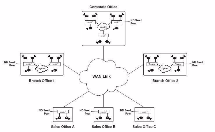
166 CHAPTER 9: CONFIGURING NETWORK DOMAINS
Figure 4 Network Domain
In a Network Domain, one or more WX switches acts as a seed device. A
Network Domain seed stores information about all of the VLANs on the
Network Domain members. The Network Domain seeds share this
information among themselves, so that every seed has an identical
database. In the example above, one WX switch at each site is a Network
Domain seed.
Each Network Domain member maintains a TCP connection to one of the
seeds. When a Network Domain member needs information about a
VLAN in a remote Mobility Domain, it consults the Network Domain seed
to which it is connected. If the seed has information about the remote
VLAN, it responds with the IP address of a WX switch where the VLAN
exists. A VLAN tunnel is then created between the WX switch and the
remote WX switch.
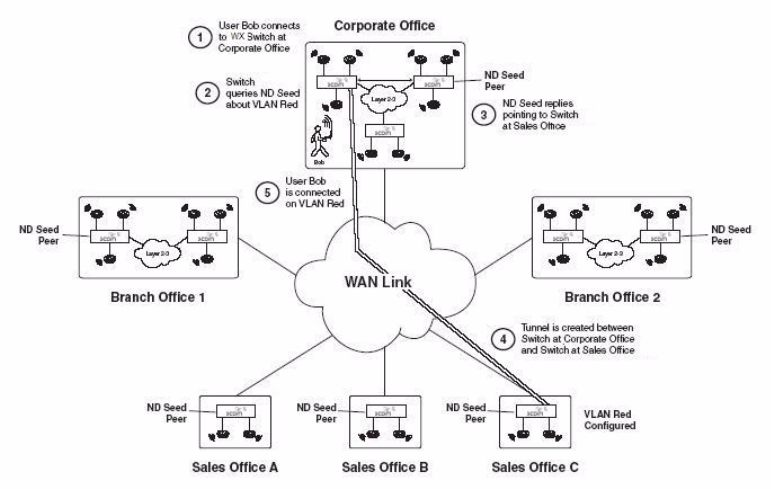
About the Network Domain Feature 167
Figure 5 illustrates how user Bob, who is based at Sales Office C gets
connectivity and is placed in a VLAN when he visits the Corporate Office.
Figure 5 How a user connects to a remote VLAN in a Network Domain
In this example, Bob establishes connectivity as follows:
1Bob connects to the wireless network at the Corporate Office. The WX
switch contacts the local Mobility Domain seed and finds that the VLAN
that Bob is configured to be on, VLAN Red, does not exist in the
Corporate Office Mobility Domain.
2Unable to find VLAN Red in the local Mobility Domain, the WX switch
then contacts the local Network Domain seed. The Network Domain seed
contains a database of all the VLANs configured on all the members of
the Network Domain. (The Network Domain seed may or may not be the
same WX switch as the Mobility Domain seed.)
3The Network Domain seed looks in its database and finds that VLAN Red
exists in the Mobility Domain at Sales Office C. The Network Domain seed
then responds with the IP address of the remote WX switch where VLAN
Red is configured.
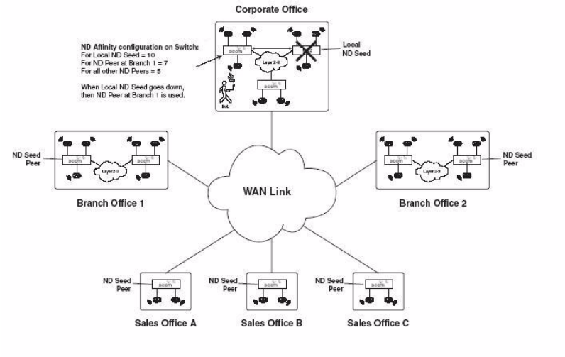
168 CHAPTER 9: CONFIGURING NETWORK DOMAINS
4A VLAN tunnel is created between the WX switch at the Corporate Office
and the WX switch at Sales Office C.
5Bob establishes connectivity on the network at the corporate office and is
placed in VLAN Red.
Network Domain
Seed Affinity
When there are multiple Network Domain seeds in an installation, a Network
Domain member connects to the seed with which it has the highest
configured affinity. If that seed is unavailable, the Network Domain member
connects to the seed with which it has the next-highest affinity.
Figure 6 illustrates how a WX switch connects to a Network Domain seed
based on its configured affinity for the seed.
Figure 6 Configuring a WX Switch’s affinity for a Network Domain seed

Configuring a Network Domain 169
In the previous example, a WX switch in the Mobility Domain at the
corporate office is configured as a member of a Network Domain that has a
local seed, as well as seeds at the two branch offices and the three sales
offices. The WX switch has an affinity value of 10 (highest) for the local seed,
and an affinity value of 7 for the seed at Branch Office 1. The WX switch has
an affinity of 5 (the default) for the other seeds in the Network Domain.
In the event that the local Network Domain seed becomes unavailable,
the WX switch then attempts to connect to the seed at Branch Office 1,
its next-highest-affinity seed. Once connected to this seed, the WX switch
then periodically attempts to connect to the local seed. When the WX
switch is able to connect to the local seed again, it drops the connection
to the seed at Branch Office 1.
When you configure a WX switch to be a member of a Network Domain,
you specify the seed(s) to which it can connect. As part of this configuration,
you can also specify the affinity the WX switch has for each seed.
Configuring a
Network Domain
To configure a Network Domain:
1Designate one or more Network Domain seed WX switches. (See
“Configuring Network Domain Seeds” on page 169.)
2Specify seed peers in the Network Domain. (See “Specifying Network
Domain Seed Peers” on page 170.)
3Configure WX switches to be part of the Network Domain. (See
“Configuring Network Domain Members” on page 171.)
You can view the status of a Network Domain, clear members, and clear
all Network Domain configuration from a WX switch.
Configuring Network
Domain Seeds
In a Network Domain, a member WX switch consults a seed WX switch to
determine a user’s VLAN membership in a remote Mobility Domain.
Use the following command to set the current WX switch as a seed
device within a specified Network Domain:
set network-domain mode seed domain-name net-domain-name
170 CHAPTER 9: CONFIGURING NETWORK DOMAINS
For example, the following command sets the current WX switch as a
seed with the Network Domain California:
WX1200# set network-domain mode seed domain-name California
success: change accepted.
If the seed in a Network Domain is also intended to be a member of the
Network Domain, you must enter the following command on the seed,
with the specified IP address pointing to the seed itself.
set network-domain mode member seed-ip ip-addr [affinity num]
For example, the following command sets the current WX switch as a
member of a Network Domain where the WX switch with IP address
192.168.9.254 is a seed:
WX1200# set network-domain mode member seed-ip 192.168.9.254
success: change accepted.
You can configure multiple seeds in a Network Domain. When multiple
Network Domain seeds are configured, a member consults the seed with
which it has the highest configured affinity.
If you are configuring multiple seeds in the same Network Domain (for
example, a seed on each physical site in the Network Domain), you must
establish a peer relationship among the seeds. See the following section.
Specifying Network
Domain Seed Peers
When multiple WX switches are configured as seed devices in a Network
Domain, they establish a peer relationship to share information about the
VLANs configured on the member devices, so that all of the Network
Domain seed peers have the same database of VLAN information.
Sharing information in this way provides redundancy in case one of the
seed peers becomes unavailable.
Use the following command on a Network Domain seed to specify
another seed as a peer:
set network-domain peer ip-addr
You enter this command on all of the seed devices in the Network
Domain, specifying each seed to every other seed, so that all of the
Network Domain seeds are aware of each other.

Configuring a Network Domain 171
For example, the following command sets the current WX switch as a
peer of the Network Domain seed with IP address 192.168.9.254:
WX1200# set network-domain peer 192.168.9.254
success: change accepted.
This command is valid on Network Domain seeds only.
Configuring Network
Domain Members
In a Network Domain, at least one seed device must be aware of each
member device. The seed maintains an active TCP connection with the
member. To configure a WX switch as a member of a Network Domain,
you specify one or more Network Domain seeds for it to use.
If you specify multiple Network Domain seeds, you can also specify the
affinity the WX switch has for each seed. The Network Domain member
initially attempts to connect to the seed with which it has the highest
affinity. If that seed is unavailable, then the WX switch attempts to
connect to the seed with which it has the next-highest affinity. If the
member connects to a seed with which it does not have the highest
configured affinity, then it periodically attempts to connect to its
highest-affinity seed. When the WX switch reconnects to the
highest-affinity seed, its communication with the next-highest-affinity
seed stops.
Use the following command to set the current WX switch as a member of
a Network Domain where a specified WX switch is a seed:
set network-domain mode member seed-ip ip-addr [affinity num]
You can enter this command multiple times on a WX switch, specifying
different Network Domain seeds with different affinity values. The affinity
value can range from 1 – 10, with 10 being the highest affinity. The
default affinity value is 5.
If the Network Domain seed is also intended to be a member of the
Network Domain, you must also enter this command on the
Network Domain seed itself.
For example, the following command sets the current WX switch as a
member of a Network Domain where the WX switch with IP address
192.168.9.254 is a seed:
WX1200# set network-domain mode member seed-ip 192.168.9.254
success: change accepted.
172 CHAPTER 9: CONFIGURING NETWORK DOMAINS
To specify 10.8.107.1 as an additional Network Domain seed for the WX
switch to connect to if the 192.168.9.254 seed is unavailable, enter the
following command:
WX1200# set network-domain mode member seed-ip 10.8.107.1
affinity 2
success: change accepted.
Displaying Network
Domain Information
To view the status of Network Domains configured on the WX switch, use
the display network-domain command. The output of the command
differs based on whether the WX switch is a member of a Network
Domain or a Network Domain seed.
For example, a WXswitch that is a Network Domain member only, output
such as the following is displayed:
WX4400# display network-domain
Member Network Domain name: California
Member State Mode
--------------- ------------- ------
10.67.1.201 UP MEMBER
10.67.1.200 UP SEED
On a WX switch that is a Network Domain seed, information is displayed
about the Network Domain seeds with which the WX switch has a peer
relationship, as well as the Network Domains of which the WX switch is a
member. For example:
WX4400# display network-domain
Network Domain name: California
Peer State
--------------- -------------
10.67.1.200 UP
Member State Mode
--------------- ------------- ------
10.67.1.201 UP MEMBER
(For more information about this command and the fields in the output,
see the Wireless LAN Switch and Controller Command Reference.)
Configuring a Network Domain 173
Clearing Network
Domain
Configuration from a
WX Switch
You can clear all Network Domain configuration from a WX switch,
regardless of whether the WX switch is a seed or a member of a Network
Domain. You may want to do this in order to change a WX switch from
one Network Domain to another, or to remove a WX switch entirely from
a Network Domain.
To clear the Network Domain configuration from the WX switch, type the
following command:
clear network-domain
This command has no effect if the WX switch is not configured as part of
a Network Domain.
Clearing a Network
Domain Seed from a
WX Switch
You can remove individual Network Domain seeds from a WX switch’s
configuration. To remove a specific Network Domain seed, type the
following command:
clear network-domain seed-ip ip-addr
When you enter this command, the Network Domain TCP connections
between the WX switch and the specified Network Domain seed are
closed.
Clearing a Network
Domain Peer from a
Network Domain
Seed
On a WX switch configured as a Network Domain seed, you can clear the
configuration of individual Network Domain peers. To remove a specific
Network Domain peer from a Network Domain seed, type the following
command:
clear network-domain peer ip-addr
This command has no effect if the WX switch is not configured as a
Network Domain seed.
Clearing Network
Domain Seed or
Member
Configuration from a
WX Switch
You can remove the Network Domain seed or member configuration
from the WX switch. To do this, enter the following command:
clear network-domain mode {seed | member}
Use the seed parameter to clear Network Domain seed configuration
from the WX switch. Use the member parameter to clear Network
Domain member configuration from the WX switch.
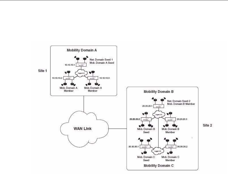
174 CHAPTER 9: CONFIGURING NETWORK DOMAINS
Network Domain
Scenario
The following scenario illustrates how to create a Network Domain
named globaldom consisting of three Mobility Domains at two
geographically separated sites. Figure 7 below illustrates this scenario.
Figure 7 Network Domain Scenario
In this scenario, there are three Mobility Domains: A, B, and C. Mobility
Domain A is located at Site 1, and Mobility Domains B and C are located
at Site 2. There are two Network Domain seeds, one at each site, that
share information about the VLANs in the three Mobility Domains. The
Network Domain seed at Site 1 is also the seed for Mobility Domain A.
The Network Domain seed at Site 2 is used by both Mobility Domains B
and C. At least one Network Domain seed is aware of each WX switch in
the installation and maintains an active TCP connection with it.
Network Domain Scenario 175
The following is the Network Domain configuration for this scenario:
1Make the WX switch with IP address 10.10.10.1 a seed of a Network
Domain called globaldom and establish a peer relationship with the WX
switch with IP address 20.20.20.1. Type the following commands:
WX1200# set network-domain mode seed domain-name globaldom
success: change accepted.
WX1200# set network-domain peer 20.20.20.1
success: change accepted.
2Make the WX switch with IP address 20.20.20.1 a seed of a Network
Domain called globaldom and establish a peer relationship with the WX
switch with IP address 10.10.10.1. Type the following commands:
WX1200# set network-domain mode seed domain-name globaldom
success: change accepted.
WX1200# set network-domain peer 10.10.10.1
success: change accepted.
3Make the three WX switches in Mobility Domain A members of the
Network Domain, specifying WX switch 10.10.10.1 as the their Network
Domain seed. Type the following command on all three WX switches:
WX1200# set mobility-domain mode member seed-ip 10.10.10.1
success: change accepted.
4Make the WX switches in Mobility Domains B and C members the
Network Domain, specifying WX switch 20.20.20.1 as the their Network
Domain seed. Type the following command on all of the WX switches in
both Mobility Domains:
WX1200# set mobility-domain mode member seed-ip 20.20.20.1
success: change accepted.
5Display the Network Domain status. Type the following command on the
WX switch with IP address 10.10.10.1:
WX1200# display network-domain
Network Domain name: globaldom
Peer State
--------------- -------------
20.20.20.1 UP
Member State Mode
--------------- ------------- ------
---------------
10.10.10.1 UP SEED
10.10.10.2 UP MEMBER
10.10.10.3 UP MEMBER
176 CHAPTER 9: CONFIGURING NETWORK DOMAINS
20.20.20.1 UP SEED
20.20.20.2 UP MEMBER
20.20.20.3 UP MEMBER
30.30.30.1 UP MEMBER
30.30.30.2 UP MEMBER
Member Network Domain name: globaldom
Member State Mode
--------------- ------------- ------
---------------
10.10.10.1 UP SEED
10.10.10.2 UP MEMBER
10.10.10.3 UP MEMBER
20.20.20.1 UP SEED
20.20.20.2 UP MEMBER
20.20.20.3 UP MEMBER
30.30.30.1 UP MEMBER
30.30.30.2 UP MEMBER

10 CONFIGURING MAP ACCESS
POINTS
MAPs contain radios that provide networking between your wired
network and IEEE 802.11 wireless users. A MAP connects to the wired
network through a 10/100 Ethernet link and connects to wireless users
through radio signals.
MAP Overview Figure 8 shows an example of a 3Com network containing MAPs and WX
switches. A MAP can be directly connected to a WX switch port or
indirectly connected to a WX switch through a Layer 2 or IPv4 Layer 3
network. For redundancy, a MAP can have one of the following
combinations of multiple connections:
Two direct connections to a single WX or two WX switches
Up to four indirect connections to WX switches through intermediate
Layer 2 or Layer 3 networks
One direct connection to a WX and up to three indirect connections
to WX switches through intermediate Layer 2 or Layer 3 networks
178 CHAPTER 10: CONFIGURING MAP ACCESS POINTS
Figure 8 Example 3Com Network
To configure MAPs, perform the following tasks, in this order:
Specify the country of operation.
Configure MAP access ports, Distributed AP connections, and dual
homing.
If required, configure radio-specific parameters, which include the
channel number, transmit power, and external antenna type.
Router
Router
Wired
authentication
client
System IP address
10.10.10.4
Port
1
Port
2
Port
4
WX
1
10.10.40.19/24
10.10.20.19/24
10.10.30.19/24
RAD
I
U
S
se
r
ve
r
s
10.10.70.20
10.10.70.40
10.10.60.18/24
10.10.60.19/24
3WXM
Port
3
Layer 2
Layer 2
10.10.10.19/24
Port
5
VL
AN
s
on
WX
1
VLAN 2 mgmt, port 5, 10.10.10.4/24
VLAN 4 blue, port 5, tag 20, 10.10.20.2/24
VLAN 3 red, port 5, tag 30
Layer 2
serial-id M9DE48BDEA200
serial-id M9DE48B6EAD00
serial-id M9DE48B012F00
serial-id M9DE48B123400
serial-id M9DE48B234500 10.10.50.19/24
external antenna
System IP address
10.10.40.4
WX
2
System IP address
10.10.40.4
WX
3
M
A
P
M
A
P
M
A
P
M
A
P
M
A
P

MAP Overview 179
You do not need to set channels and power if you use RF Auto-Tuning to
set these values. You do not need to specify an external antenna type
unless a radio uses an external antenna.
However, if you do install an external antenna, you must ensure that the
external antenna model parameter you specify exactly matches the
external antenna that is attached to the MAP’s external antenna port, in
order to meet regulatory requirements.
Configure SSID and encryption settings in a service profile.
Map the service profile to a radio profile, assign the radio profile to
radios, and enable the radios.
Country of Operation Before you can configure MAPs and radio parameters, you must specify the
country in which you plan to operate the radios. Since each country has
different regulatory environments, the country code determines the transmit
power levels and channels you can configure on the radios. MSS ensures that
the values you can configure are valid for the country you specify.
Directly Connected
MAPs and Distributed
MAPs
To configure the WX switch to support a MAP, you must first determine
how the MAP connects to the switch. There are two types of MAP to WX
connections: direct and distributed.
In direct connection, a MAP connects to a 10/100 port on a WX1200 or
WXR100. The WX port is then configured specifically for a direct
attachment to the MAP. There is no intermediate networking equipment
between the WX and MAP and only one MAP is connected to the WX
port. The WX 10/100 port provides PoE to the MAP. The WX also
forwards data only to and from the configured MAP on that port. The
port numbers on the WX configured for directly attached MAPs reference
a particular MAP.
A MAP that is not directly connected to a WX is considered a
Distributed MAP. There may be intermediate Layer 2 switches or Layer
3 IP routers between the WX and MAP. The WX may communicate to
the Distributed MAP through any network port. (A network port is any
port connecting the switch to other networking devices, such as
switches and routers, and it can also be configured for 802.1Q VLAN
tagging.) The WX contains a configuration for a Distributed MAP
based on the MAP serial number.
180 CHAPTER 10: CONFIGURING MAP ACCESS POINTS
Similar to ports configured for directly connected MAPs, distributed
MAP configurations are numbered and can reference a particular
MAP. These numbered configurations do not, however, reference any
physical port.
Distributed MAP Network Requirements
Because Distributed MAPs are not directly attached to a WX, they require
additional support from the network in order to function. Information on
the booting and operation sequence for Distributed MAPs is covered in
the section “Boot Process for Distributed MAPs” on page 189.
Power — PoE must be provided on one of the Ethernet connections
to the MAP. Be sure to use a PoE injection device that has been tested
by 3Com. (Contact 3Com for information.)
DHCP — By default, a Distributed MAP uses TCP/IP for
communication, and relies on DHCP to obtain IP parameters.
Therefore, DHCP services must be available on the subnet that the
MAP is connected to. DHCP must provide the following parameters to
the MAP:
IP address
Domain name
DNS server address
Default router address
Static IP configuration—If DHCP is not available in the network, a
Distributed MAP can be configured with static IP information that
specifies its IP address, as well as the WX switch it uses as its boot
device.
DNS — If the intermediate network between the WX switch and
Distributed MAP includes one or more IP routers, create a
3COMWX.mynetwork.com entry on the DNS server. The entry needs
to map this name to the system IP address of the switch. If the subnet
contains more than one WX in the same Mobility Domain, you can
use the system IP address of any of the WX switches. (For redundancy,
you can create more than one DNS entry, and map each entry to a
different WX switch in the subnet.)
The DNS entry allows the MAP to communicate with a WX that is not on
the MAP subnet. If the MAP is unable to locate a WX on the subnet, the
MAP sends DNS requests to 3COMWX, where the DNS suffix for
mynetwork.com is learned through DHCP.

MAP Overview 181
If only 3COMWX is defined in DNS, the MAP contacts the WX with an IP
address returned for 3COMWX.
Distributed MAPs and STP
A Distributed MAP is a leaf device. You do not need to enable STP on the
port that is directly connected to the MAP.
If Spanning Tree Protocol (STP) is enabled on the port that is directly
connected to a Distributed MAP, you might need to change the STP
configuration on the port, to allow the MAP to boot.
STP on a port directly connected to a Distributed MAP can prevent the
MAP from booting.
As part of the boot process, a MAP disables and reenables the link on the
port over which the MAP is attempting to boot. If STP is enabled on the
device that is directly connected to the port, the link state change can
cause the port on the other device to leave the forwarding state and stop
forwarding traffic. The port remains unable to forward traffic for the
duration of the STP forwarding delay.
A MAP waits 30 seconds to receive a reply to its DHCP Discover message,
then tries to boot using the other MAP port. If the boot attempt fails on
the other port also, the MAP then reattempts to boot on the first port.
The process continues until a boot attempt is successful. If STP prevents
the other device’s port from forwarding traffic during each boot attempt,
the MAP repeatedly disables and reenables the link, causing STP to
repeatedly stop the other device’s port from forwarding traffic. As a
result, the boot attempt is never successful.
To allow a MAP to boot over a link that has STP enabled, do one of the
following on the other device:
Disable STP on the port of the other device.
Enable the port fast convergence feature, if supported, on the other
device port. (On some vendors’ devices, this feature is called PortFast.)
If the other device is running Rapid Spanning Tree or Multiple
Spanning Tree, set the port into edge port mode.
182 CHAPTER 10: CONFIGURING MAP ACCESS POINTS
Distributed MAPs and DHCP Option 43
The option 43 field in a DHCP Offer message can provide a simple and
effective way for MAPs to find WX switches across an intermediate Layer
3 network, and is especially useful in networks that are geographically
distributed or have a flat domain name space. You can use the DHCP
option 43 field to provide a list of WX IP addresses, without the need to
configure DNS servers.
To use DHCP option 43, configure the option to contain a
comma-separated list of WX IP addresses or fully qualified hostnames
(host name and domain name; for example, host.domain.com), in the
following format:
ip:ip-addr1,ip-addr2,...
or
host:hostname1,hostname2,...
You can use an IP address list or a hostname list, but not both. If the list
contains both types of values, the MAP does not attempt to use the list.
The ip and host keywords can be in lowercase, uppercase (IP or HOST),
or mixed case (example: Ip, Host, and so on.) You can use spaces after
the colon or commas, but spaces are not supported within IP addresses or
hostnames. Leading zeroes are supported in IP addresses. For example,
100.130.001.1 is valid.
Valid characters in hostnames are uppercase and lowercase letters,
numbers, periods ( . ), and hyphens ( - ). Other characters are not
supported.
If you use the host option, you must configure the network’s DNS server
with address records that map the hostnames in the list to the WX IP
addresses.
After receiving a DHCP Offer containing a valid string for option 43, a
Distributed MAP sends a unicast Find WX message to each WX switch in
the list. See “How a Distributed MAP Contacts a WX Switch
(DHCP-Obtained Address)” on page 190 for a description of this process.
No configuration is required on the WX.

MAP Overview 183
MAP Parameters
Table 9 summarizes parameters that apply to individual MAPs, including
dual-homing parameters. (For information about parameters for
individual radios, see “Configuring a Radio Profile” on page 240 and
“Configuring Radio-Specific Parameters” on page 246.)
Table 9 Global MAP Parameters
Parameter Default value Description
name Based on the port or
Distributed MAP connection
number. For example:
MAP01
DAP01
MAP name.
bias high Setting a MAP’s bias on a
WX switch to high causes the
switch to be preferred over
switches with low bias, for
booting and managing the
MAP.
Note: Bias applies only to
WX switches that are
indirectly attached to the
MAP through an
intermediate Layer 2 or Layer
3 network. A MAP always
attempts to boot on MAP
port 1 first, and if a WX
switch is directly attached on
MAP port 1, the MAP boots
from it regardless of the bias
settings.
group None Named set of MAPs. MSS
load-balances user sessions
among the access points in
the group.
upgrade-firmware enable Automatic upgrade of boot
firmware.
blink disable LED blink mode — blinking
11a LED (AP2750) or health
and radio LEDs (MAP-xxx)
make the MAP visually easy
to identify.

184 CHAPTER 10: CONFIGURING MAP ACCESS POINTS
Resiliency and Dual-Homing Options for MAPs
MAPs can support a wide variety of resiliency options. Redundancy for
data link connections and for WX services can be provided to the MAP.
PoE redundancy—On MAP models that have two Ethernet ports, you
can provide PoE redundancy by connecting both ports to PoE sources.
PoE can come from a directly connected WX or a PoE injector.
Dual-homing support for PoE is automatically enabled when you
connect both MAP Ethernet ports.
Data link redundancy—You can provide data link redundancy by
connecting both Ethernet ports directly to one WX, two WX switches,
an intermediate Ethernet switch, or a combination of WX and
Ethernet switch. If an intermediate Ethernet connection is used, you
also need a Distributed MAP configuration on a WX somewhere in the
network. Dual-homing support for data link redundancy is
automatically enabled when you connect both MAP Ethernet ports.
WX redundancy—You can provide redundancy of WX services by
dual-homing the MAP to two directly connected WX switches; or by
configuring a Distributed MAP configuration either on two or more
indirectly connected WX switches, or on a combination of a directly
connected WX and one or more indirectly connected WX switches. To
provide WX redundancy on a MAP model that has only one MAP port,
configure a Distributed MAP connection on two or more indirectly
connected WX switches.
Bias On a WX, configurations for MAPs have a bias (low or high)
associated with them. The default is high. A WX with high bias for a MAP
is preferred over a WX with low bias for the MAP
If more than one WX has high bias, or the bias for all connections is the
same, the WX with the greatest capacity to add more active MAPs is
preferred. For example, if one WX has 50 active MAPs while another WX
has 60 active MAPs, and both WX switches are capable of managing 80
active MAPs, the new MAP uses the WX that has only 50 active MAPs.
Bias applies only to WX switches that are indirectly attached to the MAP
through an intermediate Layer 2 or Layer 3 network. A MAP always attempts
to boot on MAP port 1 first, and if a WX switch is directly attached on MAP
port 1, the MAP boots from it regardless of the bias settings.
(To set the bias for a MAP configuration, see “Changing Bias” on
page 227.)
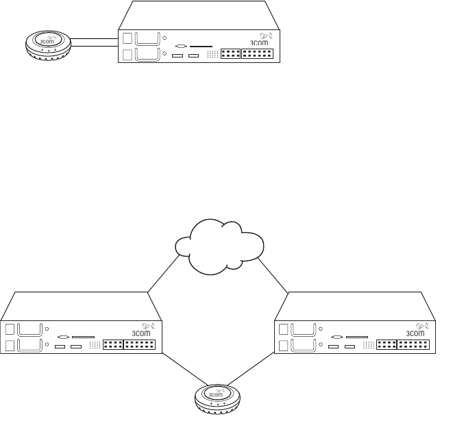
MAP Overview 185
Dual-Homed Configuration Examples
The following sections show examples of dual-homed configurations.
You can use any of these configurations to dual home a MAP model that
has two Ethernet ports. MAP models with one Ethernet port support only
the dual-homing configuration in “Dual-Homed Distributed Connections
to WX Switches on One MAP Port” on page 188.
Dual-Homed Direct Connections to a Single WX Figure 9 shows an
example of a dual-homed direct connection to one WX switch. In this
configuration, if the MAP’s active data link with the WX switch fails, the
MAP detects the link failure and restarts using the other link on the same
switch.
Figure 9 Dual-Homed Direct Connections to a Single WX
Dual-Homed Direct Connections to Two WX Switches Figure 10
shows an example of a dual-homed direct connection to two separate
WX switches. In this configuration, if the active data link fails, the MAP
detects the link failure and restarts using a link to the other switch.
Figure 10 Dual-homed Direct Connections to Two WX Switches
MAP WX switch
MAP
WX switch WX switch
Network
backbone
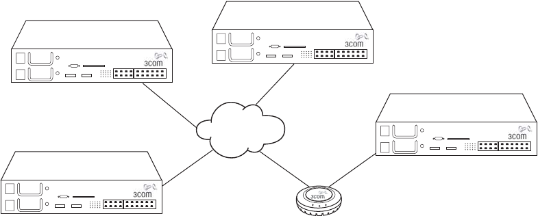
186 CHAPTER 10: CONFIGURING MAP ACCESS POINTS
Dual-Homed Direct and Distributed Connections to WX Switches
Figure 11 shows an example of a dual-homed configuration in which one
MAP connection is direct and the other is distributed over the network.
Figure 11 Dual-Homed Direct and Distributed Connections to WX Switches
In this example, the MAP port 1 is directly connected to a WX. The MAP
always attempts to boot first from the directly connected WX. The MAP
attempts to boot using MAP port 2 only if the boot attempt on port 1
fails. If the active data link fails, the WX reboots using the other link.
MAP port 1
Network
backbone
WX switch
MAP port 2
WX switch
WX switch
WX switch
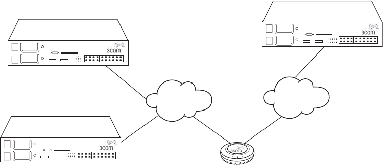
MAP Overview 187
Dual-Homed Distributed Connections to WX Switches on Both
MAP Ports Figure 12 shows an example of a dual-homed configuration
in which both MAP connections are distributed over the network.
Figure 12 Dual-homed Distributed Connections to WX Switches on Both MAP
Ports
In this configuration, the MAP first attempts to boot on its port 1. If more
than one WX has high bias or if all WX switches have the same bias, the
MAP uses the WX that has the greatest capacity for new active MAP
connections.
MAP port 1
Network
backbone
MAP port 2
Network
backbone
WX switch
WX switch
WX switch
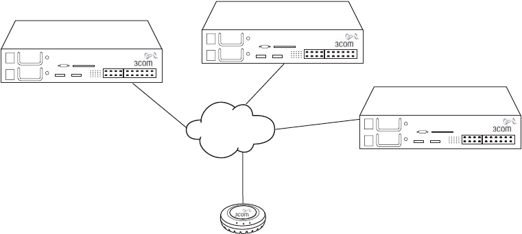
188 CHAPTER 10: CONFIGURING MAP ACCESS POINTS
Dual-Homed Distributed Connections to WX Switches on One
MAP Port Figure 13 shows an example of a MAP with a single physical
link to a network containing three WX switches.
Figure 13 Single-homed Connection to Multiple WX Switches on One MAP Port
In this configuration, the MAP sends a boot request on its connected
port. WX switches in the same subnet respond to the MAP. WX switches
with high bias for the MAP respond immediately, whereas WX switches
with low bias for the MAP respond after a brief delay.
If the switches are in another subnet, the MAP uses DNS to locate one of
the switches, and asks the switch to send the IP address of the best WX
to use, based on the bias settings on each switch and the capacity of
each switch to add new active MAP connections. The MAP then requests
its image and configuration files from the best WX.
Network
backbone
WX switch
WX switch
WX switch
MAP Overview 189
Boot Process for
Distributed MAPs
When a distributed MAP boots on the network, it uses the process
described in this section. Note that this process applies only to distributed
MAPs; it does not apply to a directly connected MAP. The boot process
for a directly connected MAP occurs strictly between the MAP and WX
switch and makes no use of the network’s DHCP or DNS services.
The boot process for a distributed MAP consists of the following steps:
1Establishing connectivity on the network
2Contacting a WX switch
3Loading and activating an operational image
4Obtaining configuration information from the WX switch
These steps are described in more detail in the following sections.
Establishing Connectivity on the Network
When a MAP is first powered on, its bootloader obtains an IP address for
the MAP. The IP address is either obtained through DHCP (the default) or
can be statically configured on the MAP.
How a Distributed MAP Obtains an IP Address through DHCP
By default, a distributed MAP obtains its IP address through DHCP. The
MAP brings up the link on the MAP’s port 1 and attempts the boot
process outlined below.
1The MAP sends a DHCP Discover message from the MAP’s port 1 to the
broadcast address.
2If a DHCP server is present on the subnet or through a router configured
to relay DHCP, the server replies with a unicast DHCP Offer message. The
Offer message must contain the following parameters:
IP address for the MAP
Domain name of the network
IP address of the network’s DNS server
IP address of the subnet’s default gateway router (gateway)
Optionally, the DHCP Offer message can also contain a list of WX IP
addresses or fully qualified hostnames, in the Option 43 field.
3The MAP broadcasts a DHCP Request to the DHCP servers, and receives an
Ack from a DHCP server. The MAP then configures its network connection
with the information contained in the Ack message from that server.

190 CHAPTER 10: CONFIGURING MAP ACCESS POINTS
Static IP Address Configuration for Distributed MAPs
In cases where DHCP is not available, you can manually assign IP address
information to a Distributed MAP. This information is configured through
the CLI.
You can configure the following information for a Distributed MAP:
aIP address, subnet mask, default gateway router, and whether the
configured static IP address information is enabled for the MAP.
bThe IP address of a suitable WX switch for the MAP to use as a boot
device.
cThe fully qualified domain name of a WX switch to use as a boot
device, and the IP address of a DNS server used to resolve the WX
switch’s name.
These items are referred to by letter in the description of how the MAP
contacts a WX switch in “How a Distributed MAP Contacts a WX Switch
(Statically Configured Address)” on page 193. If the MAP does not have
static IP address information configured, or its static IP configuration is
disabled, then the MAP obtains its IP address through DHCP.
Contacting a WX
Switch
After the MAP has an IP address, it attempts to contact a WX switch on
the network. The method used for contacting a WX switch depends on
whether the MAP’s IP address was obtained through DHCP or was
configured statically.
How a Distributed MAP Contacts a WX Switch (DHCP-Obtained
Address)
1If the DHCP Offer message contained WX IP addresses or fully qualified
hostnames in the Option 43 field, the MAP proceeds as follows:
If the DHCP Offer message contained one or more IP addresses in the
Option 43 field, the MAP sends a unicast Find WX message to each
address. The process skips to step 6.
If the DHCP Offer message contained one or more hostnames in the
Option 43 field, the MAP sends DNS Requests to the DNS server for
the IP addresses of the hosts, then sends a unicast Find WX message
to each address. The process skips to step 6.
This method requires DNS address records on the DNS server that map
the hostnames to the WX IP addresses.

MAP Overview 191
If no WX switches reply, the MAP repeatedly resends the Find WX
messages. If no WX switches reply, the process continues with step 3.
2If no IP addresses or hostnames were specified in the Option 43 field of
the DHCP Offer message, the MAP sends a Find WX message to UDP port
5000 on the subnet broadcast address.
WX switches in the same IP subnet as the MAP receive the message
and respond with a Find WX Reply message.
If the MAP is configured as a Distributed MAP on a switch and the
connection bias is high, the WX switch immediately sends a Find
WX Reply message.
If the MAP is configured as a Distributed MAP on a switch but the
connection bias is low, that WX switch waits one second, then
sends a Find WX Reply message. The delay allows switches with
high bias for the MAP to respond first.
If a WX switch that receives the Find WX message does not have
the Distributed MAP in its configuration but another WX switch in
the same Mobility Domain does, the switch waits two seconds,
then sends a Find WX Reply message with the IP address of the
best switch to use. The determination of best switch is based on
the bias settings for the MAP on each switch and on the capacity
of each switch to add new active MAP connections.
The process skips to step 6.
If no WX switches reply, the MAP repeatedly resends the Find WX
broadcast. If still no WX switches reply, the process continues with
step 3.
3If the MAP is unable to locate a WX on the subnet it is connected to, and
is unable to find a WX based on information in the DHCP option 43 field,
the MAP sends DNS requests for both 3COM and wlan-switch, where the
DNS suffix for mynetwork.com is learned through DHCP.
You must configure a DNS address record on your DNS server for the WX
IP address. Otherwise, the DNS server cannot provide the WX switch’s
address to the MAP.
4The DNS server replies with the system IP address of a WX switch.
If only 3COM is defined in DNS, the MAP sends a unicast Find WX
message to the WX switch whose IP address is returned for 3Com.
192 CHAPTER 10: CONFIGURING MAP ACCESS POINTS
If only wlan-switch is defined in DNS, the MAP sends a unicast Find
WX message to the WX switch whose IP address is returned for
wlan-switch.
If both 3Com and wlan-switch are defined in DNS, the MAP sends a
unicast Find WX message to the WX switch whose IP address is
returned for 3Com. The MAP ignores the IP address returned for
wlan-switch.
If both 3Com and wlan-switch are defined in DNS, and the MAP is
unable to contact the IP address returned for 3Com, the MAP never
contacts the IP address returned for wlan-switch. The MAP does not
boot.
5The MAP sends Find WX requests to the WX IP addresses given by the
DNS reply. If a WX receives the Find WX Request, the process continues
with step 6.
However, if no WX switches reply, the MAP repeatedly retries this
method:
If still no WX switches reply, the MAP begins the process again,
starting with the procedure under “How a Distributed MAP Contacts
a WX Switch (DHCP-Obtained Address)” on page 190, on the other
MAP port.
If the other MAP port does not have a link or the MAP has only one
port, the MAP instead restarts, and begins the process again on the
same MAP port.
66 The WX that receives the Find WX request determines the best WX for
the MAP to use, based on the bias settings for the MAP on each switch. If
more than one switch has high bias for the MAP or all switches have the
same bias, the WX suggests the switch that has the highest capacity to
add new active MAP connections.
7The WX sends a unicast Find WX Reply message to the MAP containing
the system IP address of the best WX switch to use.
8The MAP sends a unicast message to the suggested WX switch, to
request an operational image. If the MAP does not receive a reply after
10 seconds, the MAP reboots and starts the boot process over.
If a MAP does not receive a reply to a DNS request or a request for an
operational image after one minute, the MAP starts the boot process over
with a new DHCP Discover message, this time from MAP port 2.
MAP Overview 193
How a Distributed MAP Contacts a WX Switch (Statically
Configured Address)
When configuring a distributed MAP with static IP information, you can
specify the following information:
aIP address, subnet mask, default gateway router, and whether the
configured static IP address information is enabled for the MAP.
bThe IP address of a suitable WX switch for the MAP to use as a boot
device.
cThe fully qualified domain name of a WX switch to use as a boot
device, and the IP address of a DNS server used to resolve the WX
switch’s name.
This information is used in the following way when the MAP attempts to
contact a WX switch:
1If Items A and B (but not Item C) are specified, and the WX switch’s IP
address is part of the local subnet, then the AMP sends an ARP request
for its configured static IP address, to ensure that it is not already in use in
the network. The MAP then sends a Find WX message to UDP port 5000
at the WX switch’s IP address.
If the MAP receives a response from that address, it sends a unicast
message to the WX switch, to request an operational image.
If the MAP does not get a response, then it sends a Find WX message
to UDP port 5000 on the subnet broadcast address.
If the MAP receives a response to the broadcast Find WX message,
then the process continues using the procedure described under
“How a Distributed MAP Contacts a WX Switch (DHCP-Obtained
Address)” on page 190.
If there is no response to the broadcast Find WX message, then the
process skips to step 4 on page 191.
If the WX switch is not part of the local subnet, then the MAP uses the
default gateway router address to contact the WX switch.
2If Item A, but not Item B is specified, then the MAP uses the specified
static IP configuration, and broadcasts a Find WX message to the subnet.
If the MAP receives a response to the broadcast Find WX message,
then the process continues using the procedure described under
“How a Distributed MAP Contacts a WX Switch (DHCP-Obtained
Address)” on page 190.
194 CHAPTER 10: CONFIGURING MAP ACCESS POINTS
If there is no response to the broadcast Find WX message, the WX
continues broadcasting the Find WX message for a period of time. If
still no response is received, then the process skips to step 4 on page
191.
3If Items A and C are specified, the MAP sends a DNS request to resolve
the fully qualified domain name of the WX switch. If the DNS server is not
on the local subnet, the MAP uses the default gateway router address to
contact the DNS server.
If there is no response from the DNS server, then the process skips to
step 4 on page 191
If there is a response from the DNS server, then the MAP sends a Find
WX message to the WX switch.
If a response is received from the WX switch, then the MAP sends
a unicast message to the WX switch, to request an operational
image.
If a response is not received from the WX switch, then the process
skips to step 4 on page 191.
4If the MAP cannot reach the WX switch using the static IP address
information, then the MAP attempts to boot using the default boot
process; that is, by contacting a DHCP server, as described in “How a
Distributed MAP Contacts a WX Switch (DHCP-Obtained Address)” on
page 190. If the default MAP boot process does not succeed, then the
MAP again attempts to boot using its statically configured IP information.
The MAP alternates between the two boot processes until the WX switch
is contacted.
If the default MAP boot process is successful, but the DHCP response
does not include a DNS server address, then the IP address of the DNS
server specified as part of Item C is used.
MAP Overview 195
Loading and
Activating an
Operational Image
A MAP’s operational image is the software that allows it to function on
the network as a wireless access point. As part of the MAP boot process,
an operational image is loaded into the MAP’s RAM and activated. The
MAP stores copies of its operational image locally, in its internal flash
memory. The MAP can either load the locally stored image, or it can
download an operational image from the WX switch to which it has
connected.
After the MAP establishes a connection to a WX switch, the MAP’s
bootloader determines if the WX switch permits the MAP to load a local
image or if the image should be downloaded from the WX switch.
The MAP loads its local image only if the WX switch is running MSS
Version 5.0 or later, and the WX switch does not have a newer MAP
image than the one stored locally on the MAP. If the WX switch is not
running MSS Version 5.0 or later, or the WX switch has a newer version
of the MAP image than the version in the MAP’s local storage, the MAP
downloads the operational image from the WX switch.
The bootloader also compares the version of the local image to the
version available from the WX switch. If the two versions do not match,
the image is downloaded from the WX switch, so that the MAP’s local
image matches the version from the WX switch.
After an operational image is downloaded from the WX switch, it is
copied into the MAP’s flash memory. The MAP then reboots, copying the
downloaded operational image from its flash memory into RAM.
Obtaining
Configuration
Information from the
WX Switch
Once the MAP loads an operational image, either from local storage or
downloaded from a WX switch, the MAP receives configuration
information from the WX switch to which it has connected. This
information includes commands that activate the radios on the MAP,
regulate power levels, assign SSIDs, and so on.
After the MAP receives the configuration information from the WX
switch, it is then operational on the network as a wireless access point.
MAP Boot Examples
The following figures show MAP boot examples:
Figure 14 on page 196 shows an example of the boot process for a
MAP connected through a Layer 2 network.
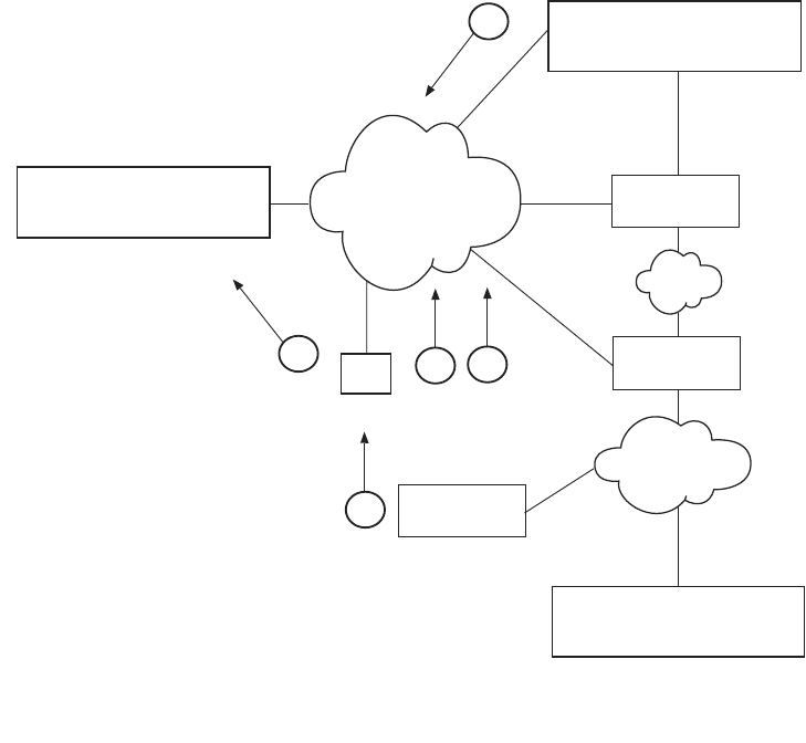
196 CHAPTER 10: CONFIGURING MAP ACCESS POINTS
Figure 15 on page 198 shows an example of the boot process for a
MAP connected through a Layer 3 network.
Figure 16 on page 200 shows an example of the boot process for a
dual-homed MAP that has one direct connection to a WX switch and
an indirect connection through a Layer 2 network.
Figure 17 on page 201 shows an example of the boot process for a
MAP that has been configured with static IP information.
Example MAP Boot
over Layer 2
Network
Figure 14 shows an example of the boot process for a MAP connected
through a Layer 2 network. WX1, WX2, and WX3 each have a
Distributed MAP configuration for the MAP.
Figure 14 MAP Booting over Layer 2 Network
Router
Router
System IP address
10.10.10.4
WX
1
Layer 2
System IP address
10.10.40.4
WX
2
Layer 2
System IP address
10.10.50.4
WX
3
DHCP Server
DAP 1
serial_id M9DE48B012F00
model AP2750
bias = low
DAP 1
serial_id M9DE48B012F00
model AP2750
bias = low
serial_id M9DE48B012F00
model AP2750
2
4
1
DAP 1
serial_id M9DE48B012F00
model AP2750
bias = high
3
5
Layer 2
MAP
MAP Overview 197
1The MAP sends a DHCP Discover message from the MAP port 1.
2DHCP server receives the Discover message (through a relay agent) and
replies with a DHCP Offer message containing IP address for the MAP,
the router IP address for the MAP IP subnet, the DNS server address, and
the domain name. MAP then sends a DHCP Request message to the
server and receives an Ack from the server.
3MAP sends a broadcast Find WX message to IP subnet broadcast address.
4WX1 and WX3 have high priority for the MAP and reply immediately.
5The MAP contacts WX1 and determines whether it should use a locally
stored operational image or download it from the WX switch.
WX1 is contacted because it has fewer active MAP connections than
WX3. Once the operational image is loaded, the MAP requests
configuration information from WX1.
198 CHAPTER 10: CONFIGURING MAP ACCESS POINTS
Example MAP Boot
over Layer 3
Network
Figure 15 shows an example of the boot process for a MAP connected
through a Layer 3 network.
Figure 15 MAP Booting over Layer 3 Network
1The MAP sends DHCP Discover message from the MAP’s port 1.
2The DHCP server replies with a DHCP Offer message containing an IP
address for the MAP, the default router IP address for the MAP’s IP
subnet, the DNS server address, and the domain name. MAP then sends a
DHCP Request message to the server and receives an Ack from the server.
3The MAP sends a broadcast Find WX message to the IP subnet broadcast
address.
4When the MAP is unable to locate a WX on the subnet it is connected to,
the MAP then sends a DNS request for 3com.example.com and
wlan.example.com.
Router
Router
System IP address
10.10.10.4
WX
1
Layer 2
System IP address
10.10.40.4
WX
2
Layer 2
System IP address
10.10.50.4
WX
3
DHCP Server
2
5
8
DAP 1
serial_id M9DE48B123400
model AP2750
bias = high
DAP 1
serial_id M9DE48B123400
model AP2750
bias = low serial_id M9DE48B123400
model AP2750
3
4
6
7
1
3COMWX.example.com =
10.10.10.4
DNS Server
Layer 2
DAP 1
serial_id M9DE48B123400
model AP2750
bias = low
MAP
MAP Overview 199
5The DNS server sends the system IP address of the WX switch mapped to
3com.example.com. In this example, the address is for WX1.
6The MAP sends a unicast Find WX message to WX1.
7WX1 receives the Find WX message and compares the bias settings on
each WX for the MAP. More than one WX has a high bias for the MAP,
so WX1 selects the WX that has the greatest capacity to add new active
MAP connections. In this example, WX1 has more capacity. WX1 sends
its own IP address in the Find WX Reply message to the MAP.
8The MAP contacts WX1 and determines whether it should use a locally
stored operational image or download it from the WX switch. Once the
operational image is loaded, the MAP requests configuration information
from WX1.
200 CHAPTER 10: CONFIGURING MAP ACCESS POINTS
Example Boot of
Dual-Homed MAP
Figure 16 shows an example of the boot process for a MAP that is dual
homed with a direct connection to WX1 and an indirect connection to
WX2 and WX3. In this configuration, since the MAP is directly connected
to a WX switch, the MAP boots using the directly connected WX switch
regardless of the bias set on any of the WX switches configured for the
MAP. Only in the event of a physical port failure would the MAP attempt
to boot from its port 2.
Figure 16 Dual-Homed MAP Booting
WX
Router
Router
Layer 2
Layer 2
1
DHCP Server
DAP 1
serial_id 0322199999
model mp-372
DAP 1
serial_id 0322199999
model mp-372
MP port 4
model mp-372
PoE enabled
serial_id 0322199999
model mp-372
Port
4
2
System IP address
10.10.10.4
WX1
active MAPs = 49
System IP address
10.10.40.4
active MAPs = 34
WX2
System IP address
10.10.50.4
active MAPs = 62
WX3
MAP Overview 201
1MAP sends a DHCP Discover message from the MAP’s port 1.
2Because WX1 is configured for direct attachment, WX1 responds
privately to the MAP and provides the MAP with its operational image (or
indicates that the MAp should use a locally stored image) and
configuration from WX1. Only in the event of a physical port failure
would the MAP attempt to boot from its port 2, in which case both WX1
and WX2 would respond to the broadcast Find WX message.
Example Boot of
MAP with Static IP
Configuration
Figure 17 shows an example of the boot process for a MAP configured
with static IP information. In the example, the MAP has been configured
to use the following:
Static IP address: 172.16.0.42, netmask: 255.255.255.0, default
router 172.16.0.20
Boot WX switch: wxr100, DNS server: 172.16.0.1
Figure 17 MAP Booting with a Static IP Address
System FQDN:
mxr2
MX Switch
Layer 2
DNS Server
172.16.0.1
2
4
1
DAP 1
static IP: 172.16.0.42
3
5
6WX Switch

202 CHAPTER 10: CONFIGURING MAP ACCESS POINTS
After the MAP is configured with the above information, the next time
the MAP boots, the following takes place:
1The MAP sends an ARP request for its own address, to ensure it is not in
use elsewhere in the network.
2The DNS server resolves the fully qualified domain name of the WX
switch, wxr100.
3The MAP sends a Find WX message to the WX switch WXR100.
4The WX switch WXR100 responds to the Find WX message
5The MAP sends a unicast message to the WX switch WXR100 and
determines whether it should use a locally stored image or download it
from the WX switch.
6Once the operational image is loaded, WX switch WXR100 sends
configuration information to the MAP.
Service Profiles A service profile controls advertisement and encryption for an SSID. You
can specify the following:
Whether SSIDs that use the service profile are beaconed
Whether the SSIDs are encrypted or clear (unencrypted)
For encrypted SSIDs, the encryption settings to use
The fallthru authentication method for users that are not
authenticated with 802.1X or MAC authentication
Table 10 lists the parameters controlled by a service profile and their
default values.
Table 10 Defaults for Service Profile Parameters
Parameter Default Value
Radio Behavior When Parameter
Set to Default Value
attr No attributes
configured Does not assign the SSID’s
authorization attribute values to SSID
users, even if attributes are not
otherwise assigned.
auth-dot1x enable When the Wi-Fi Protected Access
(WPA) information element (IE) is
enabled, uses 802.1X to authenticate
WPA clients.

MAP Overview 203
auth-fallthru web-auth Uses WebAAA for users who do not
match an 802.1X or MAC
authentication rule for the SSID
requested by the user.
auth-psk disable Does not support using a preshared key
(PSK) to authenticate WPA clients.
beacon enable Sends beacons to advertise the SSID
managed by the service profile.
cac-mode none Does not limit the number of active
user sessions based on Call Admission
Control (CAC).
cac-session 14 If session-based CAC is enabled
(cac-mode is set to session), limits the
number of active user sessions on a
radio to 14.
cipher-ccmp disable Does not use Counter with Cipher
Block Chaining Message
Authentication Code Protocol (CCMP)
to encrypt traffic sent to WPA clients.
cipher-tkip enable When the WPA IE is enabled, uses
Temporal Key Integrity Protocol (TKIP)
to encrypt traffic sent to WPA clients.
cipher-wep104 disable Does not use Wired Equivalent Privacy
(WEP) with 104-bit keys to encrypt
traffic sent to WPA clients.
cipher-wep40 disable Does not use WEP with 40-bit keys to
encrypt traffic sent to WPA clients.
cos 0If static CoS is enabled (static-cos is set
to enable), assigns CoS 0 to all data
traffic to or from clients.
dhcp-restrict disable Does not restrict a client’s traffic to only
DHCP traffic while the client is being
authenticated and authorized.
idle-client-probing enable Sends a keepalive packet (a null-data
frame) to each client every 10 seconds.
long-retry-count 5Sends a long unicast frame up to five
times without acknowledgment.
Table 10 Defaults for Service Profile Parameters (continued)
Parameter Default Value
Radio Behavior When Parameter
Set to Default Value

204 CHAPTER 10: CONFIGURING MAP ACCESS POINTS
keep-initial-vlan disable Reassigns the user to a VLAN after
roaming, instead of leaving the roamed
user on the VLAN assigned by the
switch where the user logged on.
Note: Enabling this option does not
retain the user’s initial VLAN
assignment in all cases.
no-broadcast disable Does not reduce wireless broadcast
traffic by sending unicasts to clients for
ARP requests and DHCP Offers and
Acks instead of forwarding them as
multicasts.
proxy-arp disable Does not reply on behalf of wireless
clients to ARP requests for client IP
addresses. Instead, the radio forwards
the ARP Requests as wireless
broadcasts.
psk-phrase No passphrase
defined Uses dynamically generated keys rather
than statically configured keys to
authenticate WPA clients.
psk-raw No preshared
key defined Uses dynamically generated keys rather
than statically configured keys to
authenticate WPA clients.
rsn-ie disable Does not use the RSN IE in transmitted
frames.
shared-key-auth disable Does not use shared-key
authentication.
This parameter does not enable PSK
authentication for WPA. To enable PSK
encryption for WPA, use the
set radio-profile auth-psk command.
short-retry-count 5Sends a short unicast frame up to five
times without acknowledgment.
soda disable Sygate On Demand Agent (SODA) files
are not downloaded to connecting
clients.
ssid-name 3Com Uses the SSID name 3Com.
ssid-type crypto Encrypts wireless traffic for the SSID.
static-cos disable Assigns CoS based on the QoS mode
(wmm or svp) or based on ACLs.
Table 10 Defaults for Service Profile Parameters (continued)
Parameter Default Value
Radio Behavior When Parameter
Set to Default Value

MAP Overview 205
tkip-mc-time 60000 Uses Michael countermeasures for
60,000 ms (60 seconds) following
detection of a second MIC failure
within 60 seconds.
transmit-rates 802.11a:
mandatory:
6.0,12.0,24.0
beacon-rate:
6.0
multicast-rate:
auto
disabled:
none
802.11b:
mandatory:
1.0,2.0
beacon-rate:
2.0
multicast-rate:
auto
disabled:
none
802.11g:
mandatory:
1.0,2.0,5.5,1
1.0
beacon-rate:
2.0
multicast-rate:
auto
disabled:
none
Accepts associations only from clients
that support one of the mandatory
rates.
Sends beacons at the specified rate
(6 Mbps for 802.11a, 2 Mbps for
802.11b/g).
Sends multicast data at the highest rate
that can reach all clients connected to
the radio.
Accepts frames from clients at all valid
data rates. (No rates are disabled by
default.)
user-idle-timeout 180 Allows a client to remain idle for 180
seconds (3 minutes) before MSS
changes the client’s session to the
Disassociated state.
Table 10 Defaults for Service Profile Parameters (continued)
Parameter Default Value
Radio Behavior When Parameter
Set to Default Value

206 CHAPTER 10: CONFIGURING MAP ACCESS POINTS
(To configure a service profile, see “Configuring a Service Profile” on
page 233.)
web-portal-acl portalacl
Note: This is the
default only if
the fallthru type
on the service
profile has been
set to
web-portal.
Otherwise, the
value is
unconfigured.
If set to portalacl and the service profile
fallthru is set to web-portal, radios use
the portalacl ACL to filter traffic for
Web Portal users during authentication.
If the fallthru type is web-portal but
web-portal-acl is set to an ACL other
than portalacl, the other ACL is used.
If the fallthru type is not web-portal,
radios do not use the web-portal-acl
setting.
web-portal-form Not configured For WebAAA users, serves the default
login web page or, if configured, the
SSID-specific login web page.
web-portal-session-
timeout
5Allows a Web Portal WebAAA session
to remain in the Deassociated state 5
seconds before being terminated
automatically.
wep key-index No keys defined Uses dynamic WEP rather than static
WEP.
Note: If you configure a WEP key for
static WEP, MSS continues to also
support dynamic WEP.
wep
active-multicast-index
1Uses WEP key 1 for static WEP
encryption of multicast traffic if WEP
encryption is enabled and keys are
defined.
wep
active-unicast-index
1Uses WEP key 1 for static WEP
encryption of unicast traffic if WEP
encryption is enabled and keys are
defined.
wpa-ie disable Does not use the WPA IE in transmitted
frames.
Table 10 Defaults for Service Profile Parameters (continued)
Parameter Default Value
Radio Behavior When Parameter
Set to Default Value

MAP Overview 207
Public and Private SSIDs
Each radio can support the following types of SSIDs:
Encrypted SSID — Clients using this SSID must use encryption. Use
the encrypted SSID for secured access to your enterprise network.
Clear SSID — Clients using this SSID do not use encryption. Use the
clear SSID for public access to nonsecure portions of your network.
All supported MAP models can support up to 32 SSIDs per radio. Each
SSID can be encrypted or clear, and beaconing can be enabled or
disabled on an individual SSID basis.
Each radio has 32 MAC addresses and can therefore support up to 32
SSIDs, with one MAC address assigned to each SSID as its BSSID. A MAP's
MAC address block is listed on a label on the back of the access point. If
the MAP is already deployed and running on the network, you can
display the MAC address assignments by using the display {ap | dap}
status command.
All MAC addresses on a MAP are assigned based on the MAP’s base
MAC address, as described in Table 11.
Table 11 MAC Address Allocations on MAPs
MAP Model Address Allocation
MAP All models The MAP has a base MAC address. All the other
addresses are assigned based on this address.
Ethernet
Ports
All models Ethernet port 1 equals the MAP base MAC
address.
Ethernet port 2 (if the MAP model has one)
equals the MAP base MAC address + 1.

208 CHAPTER 10: CONFIGURING MAP ACCESS POINTS
Radios
and SSIDs
AP2750 The radio MAC address equals the MAP base
MAC address.
The BSSIDs for the SSIDs configured on the
radio end in even numbers. The first BSSID is
equal to the MAP’s base MAC address. The next
BSSID is equal to the MAP’s base MAC address
+ 2, and so on.
AP7250
AP8250
AP8750
All radio MAC addresses are dynamically
allocated by the WX switch after the MAP
boots. MSS allocates a unique block of eight
consecutive addresses to each radio. Each SSID
configured on the radio uses one of the
addresses as its BSSID.
MAC allocations are not persistent across a
restart of the MAP, and a MAP might be
allocated a different set of addresses following a
restart.
AP3150
AP3750
MP-352
MP-262
MP-252
MP-52
The 802.11b/g radio equals the MAP base MAC
address.
The BSSIDs for the SSIDs configured on the
802.11b/g radio end in even numbers. The first
BSSID is equal to the MAP’s base MAC address.
The next BSSID is equal to the MAP’s base MAC
address + 2, and so on.
The 802.11a radio equals the MAP base MAC
address + 1.
The BSSIDs for the SSIDs configured on the
802.11a radio end in odd numbers. The first
BSSID is equal to the MAP’s base MAC address
+ 1. The next BSSID is equal to the MAP’s base
MAC address + 3, and so on.
MP-341
MP-241
The radio equals the MAP base MAC address.
The BSSIDs for the SSIDs configured on the
radio end in even numbers. The first BSSID is
equal to the MAP’s base MAC address. The next
BSSID is equal to the MAP’s base MAC address
+ 2, and so on.
Table 11 MAC Address Allocations on MAPs
MAP Overview 209
Encryption
Encrypted SSIDs can use the following encryption methods:
Wi-Fi Protected Access (WPA)
Non-WPA dynamic Wired Equivalent Privacy (WEP)
Non-WPA static WEP
Dynamic WEP is enabled by default.
(For more information, including configuration instructions, see
Chapter 13, “Configuring User Encryption,” on page 281.)
Radio Profiles You can easily assign radio configuration parameters to many radios by
configuring a radio profile and assigning the profile to the radios. To use
a radio, you must assign a profile to the radio. You can enable the radio
when you assign the profile.
Table 12 summarizes the parameters controlled by radio profiles.
Generally, the only radio parameters controlled by the profile that you
need to modify are the SSIDs and, if applicable, Wi-Fi Protected Access
(WPA) settings. The other parameter settings are standard.
For information about the auto-tune parameters, see Table 25 on
page 314.
Table 12 Defaults for Radio Profile Parameters
Parameter Default Value
Radio Behavior When Parameter Set to
Default Value
active-scan enable Sends probe any requests (probe requests
with a null SSID name) to solicit probe
responses from other access points.
(See “Rogue Detection and
Countermeasures” on page 567.)
beacon-interval 100 Waits 100 ms between beacons.
countermeasures Not configured Does not issue countermeasures against any
device.
(See “Rogue Detection and
Countermeasures” on page 567.)
dtim-interval 1Sends the delivery traffic indication map
(DTIM) after every beacon.

210 CHAPTER 10: CONFIGURING MAP ACCESS POINTS
(To configure a radio profile, see “Configuring a Radio Profile” on page 240.)
frag-threshold 2346 Uses the short-retry-count for frames shorter
than 2346 bytes and uses the
long-retry-count for frames that are 2346
bytes or longer.
max-rx-lifetime 2000 Allows a received frame to stay in the buffer
for up to 2000 ms (2 seconds).
max-tx-lifetime 2000 Allows a frame that is scheduled for
transmission to stay in the buffer for up to
2000 ms (2 seconds).
preamble-length short Advertises support for short 802.11b
preambles, accepts either short or long 802.11b
preambles, and generates unicast frames with
the preamble length specified by the client.
Note: This parameter applies only to
802.11b/g radios.
qos-mode wmm Classifies and marks traffic based on 802.1p
and DSCP, and optimizes forwarding
prioritization of MAP radios for Wi-Fi
Multimedia (WMM).
rfid-mode disable Radio does not function as a location
receiver in an AeroScout Visibility System.
rts-threshold 2346 Transmits frames longer than 2346 bytes by
means of the
Request-to-Send/Clear-to-Send (RTS/CTS)
method.
service-profile No service
profiles defined You must configure a service profile. The
service profile sets the SSID name and other
parameters.
wmm-powersave disable Requires clients to send a separate PSpoll to
retrieve each unicast packet buffered by the
MAP radio.
Table 12 Defaults for Radio Profile Parameters (continued)
Parameter Default Value
Radio Behavior When Parameter Set to
Default Value

MAP Overview 211
RF Auto-Tuning
The RF Auto-Tuning feature dynamically assigns channel and power
settings to MAP radios, and adjusts those settings when needed.
RF Auto-Tuning can perform the following tasks:
Assign initial channel and power settings when a MAP radio is started.
Periodically assess the RF environment and change the channel or
power setting if needed.
Change the transmit data rate or power to maintain at least the
minimum data rate with all associated clients.
By default, RF Auto-Tuning is enabled for channel configuration but
disabled for power configuration.
(For more information, see Chapter 14, “Configuring RF Auto-Tuning,”
on page 311.)
Default Radio Profile
MSS contains one default radio profile, named default. To apply common
parameters to radios, you can modify the default profile or create a new
one. When you create a new profile, the radio parameters in the profile
are set to their factory default values.
Radio-Specific Parameters
The channel number, transmit power, and external antenna parameters
are unique to each radio and are not controlled by radio profiles.
Table 13 lists the defaults for these parameters.
Table 13 Radio-Specific Parameters
Parameter Default Value Description
antennalocat
ion
indoors Location of the radio’s antenna.
Note: This parameter applies
only to MAPs that support
external antennas.

212 CHAPTER 10: CONFIGURING MAP ACCESS POINTS
Although these parameters have default values, 3Com recommends that
you change the values for each radio for optimal performance. For
example, leaving the channel number on each radio set to its default
value can result in high interference among the radios.
(To configure these parameters, see “Configuring Radio-Specific
Parameters” on page 246.)
antennatype For most MAP models, the
default is internal.
For MP-620, the default for the
802.11b/g radio is
ANT-1360-OUT. The default for
the 802.11a radio is
ANT-5360-OUT.
The default for the 802.11b/g
radio on model MP-262 is
ANT1060.
3Com external antenna model
This parameter is configurable
only on MAPs that support
external antennas.
auto-tune
max-power
Highest setting allowed for the
country of operation or highest
setting supported on the
hardware, whichever is lower
Maximum percentage of client
retransmissions a radio can
experience before RF
Auto-Tuning considers changing
the channel on the radio.
(To configure RF Auto-Tuning,
see “Configuring
RF Auto-Tuning” on page 311.)
channel 802.11b/g — 6
802.11a — Lowest valid
channel number for the
country of operation
Number of the channel in which
a radio transmits and receives
traffic
mode disable Operational state of the radio.
radio-profile None. You must add the radios
to a radio profile. 802.11 settings
tx-power Highest setting allowed for the
country of operation or highest
setting supported on the
hardware, whichever is lower.
Transmit power of a radio, in
decibels referred to 1 milliwatt
(dBm)
Table 13 Radio-Specific Parameters (continued)
Parameter Default Value Description

Configuring MAPs 213
Configuring MAPs To configure MAPs, perform the following tasks, in this order:
Specify the country of operation. (See “Specifying the Country of
Operation” on page 213.)
Configure an Auto-AP profile for automatic configuration of
Distributed MAPs. (See “Configuring an Auto-AP Profile for
Automatic MAP Configuration” on page 218.
Configure MAPs and dual homing. (See “Configuring MAP Port
Parameters” on page 224.)
If required, configure the channel, transmit power, and external
antenna type on each radio. (See “Configuring Radio-Specific
Parameters” on page 246.)
Configure a service profile to set SSID and encryption parameters. (See
“Configuring a Service Profile” on page 233.)
Configure a radio profile. (See “Configuring a Radio Profile” on
page 240.)
Map the radio profile to a service profile. (See “Mapping the Radio
Profile to Service Profiles” on page 249.)
Assign the radio profile to radios and enable the radios. (See
“Assigning a Radio Profile and Enabling Radios” on page 249.)
Specifying the
Country of Operation
You must specify the country in which you plan to operate the WX and its
MAPs. MSS does not allow you to configure or enable the MAP radios until
you specify the country of operation.
In countries where Dynamic Frequency Selection (DFS) is required, MSS
performs the appropriate check for radar. If radar is detected on a
channel, the MAP radio stops using the channel for the amount of time
specified in the specified country’s regulations. MSS also generates a log
message to notify you when this occurs.
To specify the country, use the following command:
set system countrycode code
For the country, you can specify one of the codes listed in Table 14.

214 CHAPTER 10: CONFIGURING MAP ACCESS POINTS
Table 14 Country Codes
Country Code
Algeria DZ
Argentina AR
Australia AU
Austria AT
Bahrain BH
Belgium BE
Belize BZ
Bolivia BO
Boznia and Herzegovina BA
Brazil BR
Bulgaria BG
Canada CA
Chile CL
China CN
Colombia CO
Costa Rica CR
Cote d’Ivoire CI
Croatia HR
Cyprus CY
Czech Republic CZ
Denmark DK
Dominican Republic DO
Ecuador EC
El Salvador SV
Egypt EG
Estonia EE
Finland FI
France FR
Germany DE
Greece GR
Guatemala GT
(continued)

Configuring MAPs 215
Honduras HN
Hong Kong HK
Hungary HU
Iceland IS
India IN
Indonesia ID
Ireland IE
Israel IL
Italy IT
Jamaica JM
Japan JP
Jordan JO
Kazakhstan KZ
Kenya KE
Kuwait KW
Latvia LV
Lebanon LB
Liechtenstein LI
Lithuania LT
Luxembourg LU
Macedonia, former Yugoslav
Republic of MK
Malaysia MY
Malta MT
Mauritius MU
Mexico MX
Morocco MA
Namibia NA
Netherlands NL
New Zealand NZ
Nigeria NG
Norway NO
(continued)
Table 14 Country Codes (continued)
Country Code

216 CHAPTER 10: CONFIGURING MAP ACCESS POINTS
Oman OM
Pakistan PK
Panama PA
Paraguay PY
Peru PE
Philippines PH
Poland PL
Portugal PT
Puerto Rico PR
Qatar QA
Romania RO
Russia RU
Saudi Arabia SA
Serbia CS
Singapore SG
Slovakia SK
Slovenia SI
South Africa ZA
South Korea KR
Spain ES
Sri Lanka LK
Sweden SE
Switzerland CH
Taiwan TW
Thailand TH
Trinidad and Tobago TT
Tunisia TN
Turkey TR
Ukraine UA
United Arab Emirates AE
United Kingdom GB
United States US
(continued)
Table 14 Country Codes (continued)
Country Code

Configuring MAPs 217
The current software version might not support all of the countries listed here.
To verify the configuration change, use the following command:
display system
The following commands set the country code to US (United States) and
verify the setting:
WX1200# set system countrycode US
success: change accepted.
WX1200# display system
===============================================================================
Product Name: WX1200
System Name: WX1200
System Countrycode: US
System Location:
System Contact:
System IP: 30.30.30.2
System idle timeout:3600
System MAC: 00:0B:0E:02:76:F6
===============================================================================
Boot Time: 2003-05-07 08:28:39
Uptime: 0 days 04:00:07
===============================================================================
Fan status: fan1 OK fan2 OK fan3 OK
Temperature: temp1 ok temp2 ok temp3 ok
PSU Status: Lower Power Supply DC ok AC ok Upper Power Supply missing
Memory: 115.09/496.04 (23%)
Total Power Over Ethernet : 32.000
===============================================================================
Uruguay UY
Venezuela VE
Vietnam VN
Table 14 Country Codes (continued)
Country Code
218 CHAPTER 10: CONFIGURING MAP ACCESS POINTS
Configuring an
Auto-AP Profile for
Automatic MAP
Configuration
You can use an Auto-AP profile to deploy unconfigured Distributed
MAPs. A Distributed MAP that does not have a configuration on a WX
switch can receive its configuration from the Auto-AP profile instead.
The Auto-AP profile assigns a Distributed MAP number and name to the
MAP, from among the unused valid MAP numbers available on the
switch. The Auto-AP profile also configures the MAP with the MAP and
radio parameter settings in the profile. The MAP and radio parameter
settings in the Auto-AP profile are configurable. (See “Configuring an
Auto-AP Profile” on page 220.)
The Auto-AP profile does not control SSIDs, encryption parameters, or
any other parameters managed by service profiles. You still need to
configure a service profile separately for each SSID.
A WX switch can have one Auto-AP profile.
How an Unconfigured MAP Finds a WX To Configure It
The boot process for a Distributed MAP that does not have a
configuration on a WX switch is similar to the process for configured
Distributed MAPs. After the MAP starts up, it uses DHCP to configure its
IP connection with the network. The MAP then uses the IP connection to
contact a WX switch.
The WX switch contacted by the MAP determines the best switch to use
for configuring the MAP, and sends the MAP the IP address of that
switch. The best switch to use for configuring the MAP is the switch that
has an Auto-AP profile with a high bias setting. If more than one WX has
an Auto-AP profile with a high bias setting, the switch that has the
greatest capacity to add new unconfigured MAPs is selected.
A WX with the capacity to add new unconfigured Distributed MAP is the
lesser of the following:
Maximum number of MAPs that can be configured on the WX, minus
the number that are configured
Maximum number of MAPs that can be active on the WX, minus the
number that are active

Configuring MAPs 219
For example, suppose the Mobility Domain has two WX switches, with
the capacities and loads listed in Table 15.
For WX1200 A:
The Number of MAPs that can be configured on the switch, minus the
number that are configured, is 30 - 25 = 5.
The Number of MAPs that can be active on the switch, minus the
number that are active, is 12 - 8 = 4.
The lesser of the two values is 4. The switch can have up to 4 more MAPs.
For WX1200 B:
The Number of MAPs that can be configured on the switch, minus the
number that are configured, is 30 - 20 = 10.
The Number of MAPs that can be active on the switch, minus the
number that are active, is 12 - 12 = 0.
The lesser of the two values is 0. The switch can have no more MAPs.
WX1200 A has the capacity to add 4 more MAPs, whereas WX1200 B cannot
add any more MAPs. Therefore, the WX contacted by the MAP sends WX1200
A’s IP address to the MAP. The MAP then requests a software image file and
configuration from WX1200 A. WX1200 A sends the software image and
sends configuration parameters based on the Auto-AP profile.
Configured MAPs Have Precedence Over Unconfigured MAPs
When a WX determines the WX IP address to send to a booting MAP, the
WX gives preference to MAPs that are already configured, over
unconfigured MAPs that require an Auto-AP profile. The WX can direct a
configured MAP to a WX that has active MAPs configured using the
Auto-AP profile, even if the WX does not have capacity for more active
MAPs. In this case, the WX randomly selects a MAP using the Auto-AP
profile to disconnect, and accepts a connection from the configured MAP
in its place.
Table 15 Example WX1200 MAP Capacities and Loads
WX1200 A WX1200 B
Maximum Configured 30 30
Maximum Active 12 12
Number Currently Configured 25 20
Number Currently Active 812
220 CHAPTER 10: CONFIGURING MAP ACCESS POINTS
The disconnected MAP can then begin the boot process again to find
another WX switch that has an Auto-AP profile. When the MAP is
disconnected, the MAP clients experience a service disruption, and will
attempt to associate with another MAP if available to reconnect to the
SSID they were using. If another MAP is not available to a client, the client
can still reconnect after the disconnected MAP is connected to a new WX
and finishes the boot and configuration process.
Configuring an Auto-AP Profile
The Auto-AP profile for Distributed MAP configuration is like an
individual MAP configuration, except the configuration has the name
auto instead of a Distributed MAP number.
To create an Auto-AP profile for automatic Distributed MAP
configuration, type the following command:
WX1200# set ap auto
success: change accepted.
To display the MAP settings in the Auto-AP profile, type the following
command:
WX1200# display ap <apnum> config auto
Dap auto: mode: disabled bias: high
fingerprint
boot-download-enable: YES
force-image-download: NO
Radio 1: type: 802.11g, mode: enabled, channel: dynamic
tx pwr: 15, profile: default
auto-tune max-power: default
Radio 2: type: 802.11a, mode: enabled, channel: dynamic
tx pwr: 11, profile: default
auto-tune max-power: default
This example shows the defaults for the MAP parameters you can
configure in the Auto-AP profile. Table 16 lists the configurable Auto-AP
profile parameters and their defaults. The only parameter that requires
configuration is the Auto-AP profile mode. The Auto-AP profile is
disabled by default. To use the Auto-AP profile to configure Distributed
MAPs, you must enable the profile. (See “Enabling the Auto-AP Profile”
on page 222.)

Configuring MAPs 221
MAPs that receive their configurations from the Auto-AP profile also
receive the radio settings from the radio profile used by the Auto-AP
profile. Likewise, the SSIDs and encryption settings come from the service
profiles mapped to the radio profile. To use a radio profile other than
default, you must specify the radio profile you want to use. (See
“Specifying the Radio Profile Used by the Auto-AP Profile” on page 222.)
Changing MAP Parameter Values The commands for configuring
MAP and radio parameters for the Auto-AP profile are the same as the
commands for configuring an individual Distributed MAP. Instead of
specifying a Distributed MAP number with the command, specify auto.
For more information about the syntax, see the “MAP Commands”
chapter of the Wireless LAN Switch and Controller Command Reference.
Table 16 Configurable Profile Parameters for Distributed MAPs
Parameter Default Value
MAP Parameters
bias high
blink
(Not shown in display ap config
output)
disable
force-image download disable (NO)
group (load balancing group) none
mode disabled
persistent none
upgrade-firmware
(boot-download-enable) enable (YES)
Radio Parameters
radio num auto-tune max-power default
radio num mode enabled
radio num radio-profile default
radiotype 11g
(or 11b for country codes where
802.11g is not allowed)

222 CHAPTER 10: CONFIGURING MAP ACCESS POINTS
MAP Parameters:
set dap auto bias {high | low}
set dap auto blink {enable | disable}
set dap auto force-image-download {enable | disable}
set dap auto group name
set dap auto mode {enable | disable}
set dap auto persistent [apnumber | all]
set dap auto upgrade-firmware {enable | disable}
Radio Parameters:
set dap auto radiotype {11a | 11b | 11g}
set dap auto radio {1 | 2} auto-tune max-power power-level
set dap auto radio {1 | 2} mode {enable | disable}
set dap auto radio {1 | 2} radio-profile name mode {enable |
disable}
Enabling the Auto-AP Profile To enable the Auto-AP profile for
automatic Distributed MAP configuration, type the following command:
WX# set ap auto mode enable
success: change accepted.
Specifying the Radio Profile Used by the Auto-AP Profile The
Auto-AP profile uses radio profile default by default. To use another radio
profile instead, use the following command:
set ap auto radio {1 | 2}
radio-profile name mode {enable |disable}
The following command changes the Auto-AP profile to use radio profile
autodap1 for radio 1:
WX# set ap auto radio 1 radio-profile autodap1
success: change accepted.
You must configure the radio profile before you can apply it to the
Auto-AP profile.
Configuring MAPs 223
Displaying Status Information for MAPs Configured by the
Auto-AP Profile
To display status information for MAPs configured by the Auto-AP
profile, type the following command:
WX# display ap status auto
AP: 7, AP model: AP3750, manufacturer 3Com, name: MAP07
====================================================
State: operational (not encrypted)
CPU info: IBM:PPC speed=266666664 Hz version=405GPr
id= ram=33554432
s/n=0333703027 hw_rev=A3
Uptime: 18 hours, 36 minutes, 27 seconds
Radio 1 type: 802.11g, state: configure succeed [Enabled] (802.11b protect)
operational channel: 1 operational power: 14
base mac: 00:0b:0e:00:d2:c0
bssid1: 00:0b:0e:00:d2:c0, ssid: public
bssid2: 00:0b:0e:00:d2:c2, ssid: employee-net
bssid3: 00:0b:0e:00:d2:c4, ssid: mycorp-tkip
Radio 2 type: 802.11a, state: configure succeed [Enabled]
operational channel: 64 operational power: 14
base mac: 00:0b:0e:00:d2:c1
bssid1: 00:0b:0e:00:d2:c1, ssid: public
bssid2: 00:0b:0e:00:d2:c3, ssid: employee-net
bssid3: 00:0b:0e:00:d2:c5, ssid: mycorp-tkip
The output displays auto next to the Distributed MAP number to indicate
that the MAP was configured using an Auto-AP profile.
Converting a MAP Configured by the Auto-AP Profile into a
Permanent MAP You can convert a temporary MAP configuration
created by the Auto-AP profile into a persistent MAP configuration on the
WX switch. To do so, use the following command:
set ap auto persistent {apnumber | all}
This command creates a persistent Distributed MAP configuration based
on the settings in the Auto-AP profile. The Distributed MAP name and
number assigned by the Auto-AP profile are used for the persistent entry.
For example, if the Auto-AP profile assigned the number 100 and the
name DAP100 to the MAP, the persistent configuration for the MAP has
the same number and name. In this case, use 100 as the apnumber with
display ap, set ap, or clear ap commands.

224 CHAPTER 10: CONFIGURING MAP ACCESS POINTS
The MAP continues to operate without interruption after you enter the
set ap auto persistent command. The next time the MAP is restarted,
the Auto-AP profile is not used to configure the MAP. Instead, the
persistent configuration is used. (Use the save config command to make
the MAP configuration persistent across switch restarts.)
Configuring MAP Port
Parameters
To configure a WX to connect to a MAP, see “Configuring a MAP” on
page 224.
Optionally, you also can change other parameters that affect the entire
MAP:
MAP name. (See “Changing MAP Names” on page 227.)
Dual-home bias. (See “Changing Bias” on page 227.)
Automatic firmware upgrade capability. (See “Disabling or Reenabling
Automatic Firmware Upgrades” on page 228.)
LED blink mode. (See “Enabling LED Blink Mode” on page 229.)
(For information about configuring RF Auto-Tuning settings on a radio,
see Chapter 14, “Configuring RF Auto-Tuning,” on page 311.)
Table 17 lists how many MAPs you can configure on a WX switch, and
how many MAPs a switch can boot. The numbers are for directly
connected and Distributed MAPs combined.
Configuring a MAP
Configure the MAP using the following command:
set ap apnumber serial-id serial-ID
model {2330 | 2330A | AP2750 | AP3750 | mp-52 | mp-241 |
mp-252 | mp-262 | mp-341 | mp-352 | mp-372 | mp-372-CN |
mp-372-JP | mp-422 | mp-620} [radiotype {11a |11b |11g}]
Table 17 Configurable and Bootable MAPs per WX Switch
WX Switch Model Maximum Configured Maximum Booted
WX4400 300 24, 48, 72, 96, or 120 depending
on the license.
WX2200 320 24, 48, 72, 96, or 120, depending
on the license.
WX1200 30 12
WXR100 8 3
Configuring MAPs 225
To configure a MAP model MP-372 with serial-ID 0322199999, type the
following command:
WX# set ap 1 serial-id 0322199999 model mp-372
success: change accepted.
(To specify the external antenna type, use the set ap radio antennatype
command. See “Configuring the External Antenna Model and Location”
on page 247.)
Configuring Static IP Addresses on Distributed MAPs
By default, Distributed MAPs use the procedure described in “How a
Distributed MAP Obtains an IP Address through DHCP” on page 189 to
obtain an IP address and connect to a WX switch. In some installations,
DHCP may not be available. In such a case, you can manually assign static
IP address information to the MAP.
You can also optionally specify the WX switch the Distributed MAP uses
as its boot device, and an 802.1Q VLAN tag to be applied to Ethernet
frames emitted from the distributed MAP.
When you configure static IP information for a Distributed MAP, it uses
the boot procedure described in “How a Distributed MAP Contacts a WX
Switch (Statically Configured Address)” on page 193 instead of the
default boot procedure.
Specifying IP Information To specify static IP address information for
a Distributed MAP, use the following command:
set ap apnumber boot-ip ip ip-addr netmask mask-addr gateway
gateway-addr [mode {enable | disable}]
To configure Distributed MAP 1 to use IP address 172.16.0.42 with a
24-bit netmask, and use 172.16.0.20 as its default router (gateway), type
the following command:
WX1200# set ap 1 boot-ip ip 172.16.0.42 netmask 255.255.255.0
gateway 172.16.0.20 mode enable
success: change accepted.
The next time the Distributed MAP is booted, it will use the specified IP
information. If the manually assigned IP information is incorrect, the MAP
uses DHCP to obtain its IP address, as described in “How a Distributed
MAP Obtains an IP Address through DHCP” on page 189.
226 CHAPTER 10: CONFIGURING MAP ACCESS POINTS
Specifying WX Switch Information To specify the WX switch a
Distributed MAP contacts and attempts to use as its boot device, use the
following command:
set ap apnumber boot-switch [switch-ip ip-addr] [name name
dns ip-addr] [mode {enable | disable}]
You can specify the WX switch by its fully qualified domain name; in this
case, you also specify the address of the DNS server used to resolve the
WX switch’s name. If you specify both the address of the WX switch, and
the WX switch’s name and DNS server address, then the MAP ignores the
WX switch’s address and uses the name.
When a static IP address is specified for a Distributed MAP, there is no
preconfigured DNS information or DNS name for the WX switch the
Distributed MAP attempts to use as its boot device. If you configure a
static IP address for a Distributed MAP, but do not specify a boot device,
then the WX switch must be reachable via subnet broadcast.
The following command configures Distributed MAP 1 to use the WX
switch with address 172.16.0.21 as its boot device.
WX# set ap 1 boot-switch switch-ip 172.16.0.21 mode enable
success: change accepted.
The following command configures Distributed MAP 1 to use the WX
switch with the name wxr100 as its boot device. The DNS server at
172.16.0.1 is used to resolve the name of the WX switch.
wx1200# set ap 1 boot-switch name wxr100 dns 172.16.0.1 mode
enable
success: change accepted.
Specifying VLAN information To specify 802.1Q VLAN tagging
information for a Distributed MAP, use the following command:
set ap apnumber boot-vlan vlan-tag tag-value [mode {enable |
disable}]
When this command is configured, all Ethernet frames emitted from the
Distributed MAP are formatted with an 802.1Q tag with a specified VLAN
number. Frames sent to the Distributed MAP that are not tagged with
this value are ignored.

Configuring MAPs 227
The following command configures Distributed MAP 1 to use VLAN tag
100:
WX1200# set ap 1 boot-vlan vlan-tag 100 mode enable
success: change accepted.
Clearing a MAP from the Configuration
To clear MAP settings from a port, use the following command:
When you clear a MAP, MSS ends user sessions that are using the MAP.
clear port type port-list
This command resets the port as a network port and removes all
MAP-related parameters from the port.
The clear port type command does not place the cleared port in any
VLAN, not even in the default VLAN (VLAN 1). To use the cleared port in
a VLAN, you must add the port to the VLAN. (For instructions, see
“Adding Ports to a VLAN” on page 92.)
To clear a MAP, use the following command:
clear ap apnumber
Changing MAP Names
The default name of a directly attached MAP is based on the port number
of the MAP access port attached to the MAP. For example, the default
name for a MAP on MAP access port 1 is MAP01. The default name of a
Distributed MAP is based on the number you assign to it when you
configure the connection. For example, the default name for Distributed
MAP 1 is AP01.
MAP names appear in the output of some CLI display commands and in
3Com Wireless Switch Manager. To change the name of a MAP, use the
following command:
set ap apnumber name name
Changing Bias
The CLI commands described in this section enable you to change the
bias for a MAP.
To change the bias of a MAP, use the following command:
set ap apnumber bias {high | low}
228 CHAPTER 10: CONFIGURING MAP ACCESS POINTS
The default bias is high.
To change the bias for a Distributed MAP to low, type the following
command:
WX# set ap 1 bias low
success: change accepted.
Disabling or Reenabling Automatic Firmware Upgrades
A MAP can automatically upgrade its boot firmware by loading the
upgrade version of the firmware from a WX switch when the MAP is
booting. Automatic firmware upgrades are enabled by default.
To disable or reenable automatic firmware upgrades, use the following
command:
set ap apnumber upgrade-firmware {enable |disable}
Forcing a MAP To Download its Operational Image from the WX
A MAP’s operational image is the software that allows it to function on
the network as a wireless access point. As part of the MAP boot process,
an operational image is loaded into the MAP’s RAM and activated. The
MAP stores copies of its operational image locally, in its internal flash
memory. At boot time, the MAP can either load the locally stored image,
or it can download an operational image from the WX switch to which it
has connected.
By default, a MAP model that can locally store a software image on the
MAP will load the locally stored image instead of downloading its image
from the WX switch.
To force the MAP to always download its image from the WX switch
instead, use the following command:
set {ap port-list | dap dap-num} force-image-download {enable
| disable}
A change to the forced image download option takes place the next time
the MAP is restarted.
Even when forced image download is disabled (the default), the MAP still
checks with the WX switch to verify that the MAP has the latest image,
and to verify that the WX is running MSS Version 5.0 or later.

Configuring MAPs 229
The MAP loads its local image only if the WX is running MSS Version 5.0
or later and does not have a newer MAP image than the one in the
MAP’s local storage. If the switch is not running MSS Version 5.0 or later,
or the WX has a newer version of the MAP image than the version in the
MAP’s local storage, the MAP loads its image from the WX.
The forced image download option is not applicable to MAP models
MP-52, MP-101, and MP-122.
Enabling LED Blink Mode
When blink mode is enabled on an AP2750, the 11a LED blinks on and
off. By default, LED blink mode is disabled. If enabled, blink mode
continues until you disable it.
When blink mode is enabled on an AP7250, the Radio LED flashes red
and the Power LED flashes green/orange. The Ethernet LED does not
change.
Changing the LED blink mode does not alter operation of the MAP. Only
the behavior of the LEDs is affected.
To enable or disable LED blink mode, use the following command:
set ap apnumber blink {enable | disable}
Configuring MAP-WX
Security
MSS provides security for management traffic between WX switches and
Distributed MAPs. When the feature is enabled, all management traffic
between Distributed MAPs that support encryption and the WX is
encrypted. MAP-WX security is set to optional by default.
The encryption uses RSA as the public key crypto system, with AES-CCM
for data encryption and integrity checking and HMAC-MD5 for keyed
hashing and message authentication during the key exchange. Bulk data
protection is provided by AES in CCM mode (AES CTR for encryption and
AES-CBC-MAC for data integrity). A 64-bit Message Authentication Code
is used for data integrity
This feature applies to Distributed MAPs only, not to directly connected
MAPs configured on MAP access ports.

230 CHAPTER 10: CONFIGURING MAP ACCESS POINTS
The maximum transmission unit (MTU) for encrypted MAP management
traffic is 1498 bytes, whereas the MTU for unencrypted management
traffic is 1474 bytes. Make sure the devices in the intermediate network
between the WX switch and Distributed MAP can support the higher MTU.
Encryption Key Fingerprint
MAPs are configured with an encryption key pair at the factory. The
fingerprint for the public key is displayed on a label on the back of the
MAP, in the following format:
RSA
aaaa:aaaa:aaaa:aaaa:
aaaa:aaaa:aaaa:aaaa
If the MAP is already installed, you can display the fingerprint in MSS.
(See “Finding the Fingerprint” on page 231.)
Encryption Options
By default, a WX can configure and manage a Distributed MAP regardless
of whether the MAP has an encryption key, and regardless of whether
you have confirmed the fingerprint by setting it in MSS.
You can configure a WX to require Distributed MAPs to have an
encryption key. In this case, the WX also requires their fingerprints to be
confirmed in MSS. When MAP security is required, a MAP can establish a
management session with the WX only if its fingerprint has been
confirmed in MSS.
If you do not want any MAPs to use encryption for management
information, you can disable the feature.

Configuring MAPs 231
Table 18 lists the MAP security options and whether a MAP can establish
a management session with a WX based on the option settings.
Verifying a MAP Fingerprint on a WX Switch
To verify a MAP fingerprint, find the fingerprint and use the set ap
fingerprint command to enter the fingerprint in MSS.
Finding the Fingerprint A MAP fingerprint is listed on a label on the
back of the MAP. (See “Encryption Key Fingerprint” on page 230.)
If the MAP is already installed and operating, use the display ap status
command to display the fingerprint. The following example shows
information for Distributed MAP 8, including its fingerprint:
WX# display ap status 8
AP: 7, AP model: AP3750, manufacturer: 3Com, name: AP08
fingerprint: b4:f9:2a:52:37:58:f4:d0:10:75:43:2f:45:c9:52:c3
====================================================
State: operational (not encrypted)
CPU info: IBM:PPC speed=266666664 Hz version=405GPr
id=0x29f1886d447f111a ram=33554432
s/n=0424000779 hw_rev=A3
Uptime: 1 hours, 8 minutes, 17 seconds
Radio 1 type: 802.11g, state: configure succeed [Enabled]
operational channel: 1 operational power: 1
base mac: 00:0b:0e:0a:60:00
bssid1: 00:0b:0e:0a:60:00, ssid: public
Table 18 MAP Security Requirements
MAP Security
Setting
MAP Has
Fingerprint?
Fingerprint
Verified in MSS?
MAP Can Establish
Management
Session with Switch?
MAP Security
Required Yes Yes Yes
No No
No Not Applicable No
MAP Security
Optional Yes Yes Yes*
* MSS generates a log message listing the MAP serial number and fingerprint so
you can verify the MAP’s identity. (See “Fingerprint Log Message” on page 233.)
No Yes*
No Not Applicable Yes

232 CHAPTER 10: CONFIGURING MAP ACCESS POINTS
bssid2: 00:0b:0e:0a:60:02, ssid: 3Com
Radio 2 type: 802.11a, state: configure succeed [Enabled]
operational channel: 48 operational power: 11
base mac: 00:0b:0e:0a:60:01
bssid1: 00:0b:0e:0a:60:01, ssid: public
bssid2: 00:0b:0e:0a:60:03, ssid: 3Com
The fingerprint is displayed regardless of whether it has been verified in
MSS.
The display ap config command lists a MAP fingerprint only if the
fingerprint has been verified in MSS. If the fingerprint has not been
verified, the fingerprint info in the command output is blank
Verifying a Fingerprint on a WX Switch To verify a MAP fingerprint,
find the fingerprint and use the set ap fingerprint command to enter the
fingerprint in MSS.
Setting the MAP Security Requirement on a WX
You can configure the WX to require all Distributed MAPs to have
encryption keys. In this case, the WX does not establish a management
session with a Distributed MAP unless the MAP has a key, and you have
confirmed the fingerprint of the key in MSS.
A change to MAP security support does not affect management sessions
that are already established. To apply the new setting to a MAP, restart
the MAP.
To configure MAP security requirements, use the following command:
set ap security {require | optional | none}
The require option enforces encryption of management traffic for all
Distributed MAPs, and requires the key fingerprints to be confirmed in
MSS. The none option disables encryption of management traffic for all
Distributed MAPs. The default is optional, which allows connection to
MAPs with or without encryption.
The following command configures a WX to require Distributed MAPs to
have encryption keys:
WX# set ap security require
Configuring MAPs 233
Fingerprint Log Message
If MAP encryption is optional, and a MAP whose fingerprint has not been
verified in MSS establishes a management session with the WX, MSS
generates a log message such as the following:
AP-HS:(secure optional)configure AP M9DE48B012F00 with
fingerprint c6:98:9c:41:32:ab:37:09:7e:93:79:a4:ca:dc:ec:fb
The message lists the serial number and fingerprint of the MAP. You can
check this information against your records to verify that the MAP is
authentic.
Configuring a Service
Profile
A service profile is a set of parameters that control advertisement
(beaconing) and encryption for an SSID, as well as default authorization
attributes that apply to users accessing the SSID.
This section describes how to create a service profile and set some basic
SSID parameters. To configure other service profile parameters, see the
following:
Chapter 13, “Configuring User Encryption,” on page 281.
Chapter 15, “Configuring Quality of Service” on page 327
“Configuring the Web Portal WebAAA Session Timeout Period” on
page 477
“Assigning SSID Default Attributes to a Service Profile” on page 493.
Chapter 24, “Configuring SODA Endpoint Security for a WX Switch,”
on page 543
(For a list of the parameters controlled by service profiles and their
defaults, see Table 10 on page 202.)
(To display service profile settings, see “Displaying Service Profile
Information” on page 259.)
Creating a Service Profile
To create a service profile and assign an SSID to it, use the following
command:
set service-profile name ssid-name ssid-name
An SSID can be up to 32 alphanumeric characters long.
234 CHAPTER 10: CONFIGURING MAP ACCESS POINTS
You can include blank spaces in the name, if you delimit the name with
single or double quotation marks. You must use the same type of
quotation mark (either single or double) on both ends of the string.
The following command configures a service profile named corp1, and
assigns SSID mycorp_rnd to it:
WX1200# set service-profile corp1 ssid-name mycorp_rnd
success: change accepted.
The following command applies the name corporate users to the SSID
managed by service profile mycorp_srvcprf:
WX1200# set service-profile mycorp_srvcprf ssid-name
“corporate users”
success: change accepted.
Removing a Service Profile
To remove a service profile, use the following command:
clear service-profile name
[soda {agent-directory | failure-page | remediation-acl |
success-page | logout-page}]
The soda options reset Sygate On-Demand (SODA) settings to their
default values. If you omit the soda option, the service profile specified
by name is completely removed.
Changing a Service Profile Setting
To change a setting in a service profile without removing the profile, use
the set service-profile command for the setting you want to change. Do
not use the clear service-profile command.
Disabling or Reenabling Encryption for an SSID
To specify whether the SSID is encrypted or unencrypted, use the
following command:
set service-profile name ssid-type [clear |crypto]
The default is crypto.
Disabling or Reenabling Beaconing of an SSID
To specify whether the SSID is beaconed, use the following command:
set service-profile name beacon {enable |disable}
Configuring MAPs 235
SSIDs are beaconed by default.
A MAP radio responds to an 802.11 probe any request only for a
beaconed SSID. A client that sends a probe any request receives a
separate response for each of the beaconed SSIDs supported by a radio.
For a nonbeaconed SSID, radios respond only to directed 802.11 probe
requests that match the nonbeaconed SSID’s SSID string.
When you disable beaconing for an SSID, the radio still sends beacon
frames, but the SSID name in the frames is blank.
Changing the Fallthru Authentication Type
By default, MSS uses WebAAA for users who do not match an 802.1X or
MAC authentication rule, and therefore fall through these authentication
types. You can change the fallthru method to last-resort or none.
To change the fallthru method, use the following command:
set service-profile name auth-fallthru
{last-resort |none |web-auth}
(For more information about network user authentication, see
“Configuring AAA for Network Users” on page 433.)
Changing Transmit Rates
Each type of radio (802.11a, 802.11b, and 802.11g) that provides service
to an SSID has a set of rates the radio is allowed to use for sending
beacons, multicast frames, and unicast data. The rate set also specifies
the rates clients must support in order to associate with a radio.
Table 19 lists the rate settings and their defaults.

236 CHAPTER 10: CONFIGURING MAP ACCESS POINTS
Table 19 Transmit Rates
Parameter Default Value Description
mandatory 11a— 6.0,12.0,24.0
11b—1.0,2.0
11g—1.0,2.0,5.5,11.0
Set of data transmission rates that
clients are required to support in order
to associate with an SSID on a MAP
radio. A client must support at least one
of the mandatory rates.
These rates are advertised in the basic
rate set of 802.11 beacons, probe
responses, and reassociation response
frames sent by MAP radios.
Data frames and management frames
sent by MAP radios use one of the
specified mandatory rates.
The valid rates depend on the radio type:
11a—6.0, 9.0, 12.0, 18.0, 24.0,
36.0, 48.0, 54.0
11b—1.0, 2.0, 5.5, 11.0
11g—1.0, 2.0, 5.5, 6.0, 9.0, 11.0,
12.0, 18.0, 24.0, 36.0, 48.0, 54.0
Use a comma to separate multiple rates;
for example: 6.0,9.0,12.0
disabled None. All rates applicable
to the radio type are
supported by default.
Data transmission rates that MAP radios
will not use to transmit data. This
setting applies only to data sent by the
MAP radios. The radios will still accept
frames from clients at disabled data
rates.
The valid rates depend on the radio type
and are the same as the valid rates for
mandatory.
If you disable a rate, you cannot use the
rate as a mandatory rate or the beacon
or multicast rate. All rates that are
applicable to the radio type and that are
not disabled are supported by the radio.
beacon-rate 11a—6.0
11b—2.0
11g—2.0
Data rate of beacon frames sent by
MAP radios. This rate is also used for
probe-response frames.
The valid rates depend on the radio type
and are the same as the valid rates for
mandatory. However, you cannot set
the beacon rate to a disabled rate.

Configuring MAPs 237
To change transmit rates for a service profile, use the following
command:
set service-profile name transmit-rates {11a | 11b | 11g}
mandatory rate-list [disabled rate-list] [beacon-rate rate]
[multicast-rate {rate | auto}]
The following command sets 802.11a mandatory rates for service profile
sp1 to 6 Mbps and 9 Mbps, disables rates 48 Mbps and 54 Mbps, and
changes the beacon rate to 9 Mbps:
WX1200# set service-profile sp1 transmit-rates 11a mandatory
6.0,9.0 disabled 48.0,54.0 beacon-rate 9.0
success: change accepted.
Enforcing the Data Rates
By default, the rate set is not enforced, meaning that a client can
associate with and transmit data to the MAP using a disabled data rate,
although the MAP does not transmit data back to the client at the
disabled rate.
You can configure MSS to enforce the data rates, which means that a
connecting client must transmit at one of the mandatory or standard
rates in order to associate with the MAP. When data rate enforcement is
enabled, clients transmitting at the disabled rates are not allowed to
associate with the MAP.
multicast-rate auto for all radio types Data rate of multicast frames sent by
MAP radios.
rate—Sets the multicast rate to a
specific rate. The valid rates depend
on the radio type and are the same
as the valid rates for mandatory.
However, you cannot set the
multicast rate to a disabled rate.
auto—Sets the multicast rate to the
highest rate that can reach all clients
connected to the MAP radio.
Table 19 Transmit Rates (continued)
Parameter Default Value Description
238 CHAPTER 10: CONFIGURING MAP ACCESS POINTS
Data rate enforcement is useful if you want to completely prevent clients
from transmitting at disabled data rates. For example, you can disable
slower data rates so that clients transmitting at these rates do not
consume bandwidth on the channel at the expense of clients transmitting
at faster rates.
Data rate enforcement is disabled by default. To enable data rate
enforcement for a radio profile, use the following command:
set radio-profile profile-name rate-enforcement mode {enable
| disable}
For example, the following command enables data rate enforcement for
radio profile rp1.
WX# set radio-profile rp1 rate-enforcement mode enable
The following command sets a 802.11g mandatory rate for service profile
sp1 to 54 Mbps and disables rates 1.0 Mbps and 2.0 Mbps:
WX# set service-profile sp1 transmit-rates 11g mandatory 54.0
disabled 1.0,2.0
The following command maps radio profile rp1 to service profile sp1.
WX# set radio-profile rp1 service-profile sp1
After these commands are entered, if a client transmitting with a data
rate of 1.0 Mbps or 2.0 Mbps attempts to associate with a MAP managed
by service profile sp1, that client is not allowed to associate with the
MAP.
Disabling Idle-Client Probing
By default, a MAP radio sends keepalive messages (idle-client probes)
every 10 seconds to each client that has an active session on the radio, to
verify that the client is still active. The probes are unicast null-data frames.
Normally, a client that is still active sends an Ack in reply to an idle-client
probe.
If a client does not send any data or respond to any idle-client probes
before the user idle timeout expires (see “Changing the User Idle
Timeout” on page 239), MSS changes the client’s session to the
Disassociated state.
Configuring MAPs 239
Responding to keepalive messages requires power use by a client. If you
need to conserve power on the client (for example, on a VoIP handset),
you can disable idle-client probing.
To disable or reenable idle-client probing, use the following command:
set service-profile name idle-client-probing {enable |
disable}
The following command disables idle-client probing on service profile
sp1:
WX1200# set service-profile sp1 idle-client-probing disable
success: change accepted.
Changing the User Idle Timeout
The user idle timeout specifies the number of seconds a client can remain
idle before the WX changes the client’s session to the Disassociated state.
A client is considered to be idle if it does not send data and does not
respond to idle-client probes. You can specify a timeout value from 20 to
86400 seconds. The default is 180 seconds (3 minutes). To disable the
user-idle timeout, set it to 0.
To change the user-idle timeout, use the following command:
set service-profile name user-idle-timeout seconds
The following command increases the user idle timeout to 360 seconds
(6 minutes):
WX1200# set service-profile sp1 user-idle-timeout 360
success: change accepted.
Changing the Short Retry Threshold
The short retry threshold specifies the number of times a radio can send a
short unicast frame for an SSID without receiving an acknowledgment for
the frame. A short unicast frame is a frame that is shorter than the RTS
threshold.
To change the short retry threshold, use the following command:
set service-profile name short-retry threshold
The threshold can be a value from 1 through 15. The default is 5.
240 CHAPTER 10: CONFIGURING MAP ACCESS POINTS
To change the short retry threshold for service profile sp1 to 3, type the
following command:
WX1200# set service-profile sp1 short-retry 3
success: change accepted.
Changing the Long Retry Threshold
The long retry threshold specifies the number of times a radio can send a
long unicast frame for an SSID without receiving an acknowledgment for
the frame. A long unicast frame is a frame that is equal to or longer than
the RTS threshold.
To change the long retry threshold, use the following command:
set service-profile name long-retry threshold
The threshold can be a value from 1 through 15. The default is 5.
To change the long retry threshold for service profile sp1 to 8, type the
following command:
WX1200# set service-profile sp1 long-retry 8
success: change accepted.
Configuring a Radio
Profile
A radio profile is a set of parameters that apply to multiple radios. You
can easily assign configuration parameters to many radios by configuring
a profile and assigning the profile to the radios.
To configure a radio profile:
Create a new profile.
Change radio parameters.
Map the radio profile to one or more service profiles.
(For a list of the parameters controlled by radio profiles and their defaults,
see Table 12 on page 209.)
The channel number, transmit power, and external antenna type are
unique to each radio and are not controlled by radio profiles. (To
configure these parameters, see “Configuring Radio-Specific Parameters”
on page 246.)
(To display radio profile information, see “Displaying Radio Profile
Information” on page 260.)

Configuring MAPs 241
Creating a New Profile
To create a radio profile, use the following command:
set radio-profile name [mode {enable | disable}]
Specify a name of up to 16 alphanumeric characters. Do not include the
mode enable or mode disable option.
After you create the radio profile, you can use the enable and disable
options to enable or disable all radios that use the profile.
To configure a new radio profile named rp1, type the following
command:
WX1200# set radio-profile rp1
success: change accepted.
To assign the profile to one or more radios, use the set ap radio
radio-profile command. (See “Assigning a Radio Profile and Enabling
Radios” on page 249.)
Changing Radio Parameters
To change individual parameters controlled by a radio profile, use the
commands described in the following sections.
You must disable all radios that are using a radio profile before you can
change parameters in the profile. (See “Disabling or Reenabling All Radios
Using a Profile” on page 250.)
Changing the Beacon Interval The beacon interval is the rate at
which a radio advertises its beaconed SSID(s). To change the beacon
interval, use the following command:
set radio-profile name beacon-interval interval
The interval can be a value from 25 ms through 8191 ms. The default is 100.
The beacon interval does not change even when advertisement is
enabled for multiple SSIDs. MSS still sends one beacon for each SSID
during each beacon interval.
To change the beacon interval for radio profile rp1 to 200 ms, type the
following command:
WX1200# set radio-profile rp1 beacon-interval 200
success: change accepted.
242 CHAPTER 10: CONFIGURING MAP ACCESS POINTS
Changing the DTIM Interval The DTIM interval specifies the number
of times after every beacon that a radio sends a delivery traffic indication
map (DTIM). A MAP sends the multicast and broadcast frames stored in
its buffers to clients who request them in response to the DTIM. The
DTIM interval applies to both the beaconed SSID and the unbeaconed
SSID.
The DTIM interval does not apply to unicast frames. A MAP also stores
unicast frames in buffer memory, but the MAP includes information
about the buffered unicast frames in each beacon frame. When a user
station receives a beacon frame that advertises unicast frames destined
for the station, the station sends a request for the frames and the MAP
transmits the requested frames to the user station.
To change the DTIM interval, use the following command:
set radio-profile name dtim-interval interval
The interval can be a value from 1 through 31. The default is 1.
To change the DTIM interval for radio profile rp1 to 2, type the following
command:
WX1200# set radio-profile rp1 dtim-interval 2
success: change accepted.
Changing the RTS Threshold The RTS threshold specifies the
maximum length a frame can be before a radio uses the
Request-to-Send/Clear-to-Send (RTS/CTS) method to send the frame. The
RTS/CTS method clears the air of other traffic to avoid corruption of the
frame due to a collision with another frame.
When a frame is long enough for the RTS/CTS method to be applicable,
the radio sends a Request-To-Send (RTS) message addressed to the
intended receiver for the frame. The receiver replies with a Clear-To-Send
(CTS) message. When the radio receives the CTS message, the radio
transmits the frame and waits for an acknowledgment from the receiver.
The radio does not transmit additional frames until receiving the
acknowledgment.
Any other user station that overhears the RTS or CTS message stops
transmitting until the station overhears the acknowledgment message.
Configuring MAPs 243
To change the RTS threshold, use the following command:
set radio-profile name rts-threshold threshold
The threshold can be a value from 256 bytes through 3000 bytes. The
default is 2346.
To change the RTS threshold for radio profile rp1 to 1500 bytes, type the
following command:
WX1200# set radio-profile rp1 rts-threshold 1500
success: change accepted.
Changing the Fragmentation Threshold The fragmentation
threshold specifies the longest a frame can be without being fragmented
into multiple frames by a radio before transmission. To change the
fragmentation threshold, use the following command:
set radio-profile name frag-threshold threshold
The threshold can be a value from 256 through 2346. The default is
2346.
To change the fragmentation threshold for radio profile rp1 to 1500
bytes, type the following command:
WX1200# set radio-profile rp1 frag-threshold 1500
success: change accepted.
Changing the Maximum Receive Threshold The maximum receive
threshold specifies the number of milliseconds a frame received by a radio
can remain in buffer memory. To change the maximum receive lifetime,
use the following command:
set radio-profile name max-rx-lifetime time
The time can be from 500 ms (0.5 second) through 250,000 ms
(250 seconds). The default is 2000 ms (2 seconds).
To change the maximum receive threshold for radio profile rp1 to
4000 ms, type the following command:
WX1200# set radio-profile rp1 max-rx-lifetime 4000
success: change accepted.
244 CHAPTER 10: CONFIGURING MAP ACCESS POINTS
Changing the Maximum Transmit Threshold The maximum
transmission threshold specifies the number of milliseconds a frame
scheduled to be transmitted by a radio can remain in buffer memory. To
change the maximum transmit lifetime, use the following command:
set radio-profile name max-tx-lifetime time
The time can be from 500 ms (0.5 second) through 250,000 ms
(250 seconds). The default is 2000 ms (2 seconds).
To change the maximum transmit threshold for radio profile rp1 to
4000 ms, type the following command:
WX1200# set radio-profile rp1 max-tx-lifetime 4000
success: change accepted.
Changing the Preamble Length By default, 802.11b/g radios
advertise support for frames with short preambles and can support
frames with short or long preambles.
An 802.11b/g radio generates unicast frames to send to a client with the
preamble length specified by the client. An 802.11b/g radio always uses a
long preamble in beacons, probe responses, and other broadcast or
multicast traffic.
Generally, clients assume access points require long preambles and
request to use short preambles only if the access point with which they
are associated advertises support for short preambles. You can disable
the advertisement of support for short preambles by setting the preamble
length value to long. In this case, clients assume that the access point
supports long preambles only and the clients request long preambles.
Changing the preamble length value affects only the support advertised
by the radio. Regardless of the preamble length setting (short or long),
an 802.11b/g radio accepts and can generate 802.11b/g frames with
either short or long preambles.
If any client associated with an 802.11b/g radio uses long preambles for
unicast traffic, the MAP still accepts frames with short preambles but
does not transmit any frames with short preambles. This change also
occurs if the access point overhears a beacon from an 802.11b/g radio on
another access point that indicates the radio has clients that require long
preambles.

Configuring MAPs 245
The default preamble length value is short. This command does not
apply to 802.11a radios.
To change the preamble length advertised by 802.11b/g radios, use the
following command:
set radio-profile name preamble-length {long | short}
To configure 802.11b/g radios that use the radio profile rp_long to
advertise support for long preambles instead of short preambles, type the
following command:
WX1200# set radio-profile rp_long preamble-length long
success: change accepted.
Resetting a Radio Profile Parameter to its Default Value
To reset a radio profile parameter to its default value, use the following
command:
clear radio-profile name parameter
The parameter can be one of the radio profile parameters listed in
Table 12 on page 209.
Make sure you specify the radio profile parameter you want to reset. If
you do not specify a parameter, MSS deletes the entire profile from the
configuration.
All radios that use this profile must be disabled before you can delete the
profile. If you specify a parameter, the setting for the parameter is reset
to its default value. The settings of the other parameters are unchanged
and the radio profile remains in the configuration. If you do not specify a
parameter, the entire radio profile is deleted from the configuration.
To disable the radios that are using radio profile rp1 and reset the
beaconed-ssid parameter to its default value, type the following
commands:
WX1200# set radio-profile rp1 mode disable
WX1200# clear radio-profile rp1 beaconed-ssid
success: change accepted.
Removing a Radio Profile
To remove a radio profile, use the following command:
clear radio-profile name

246 CHAPTER 10: CONFIGURING MAP ACCESS POINTS
You must disable all radios that are using a radio profile before you can
remove the profile. (See “Disabling or Reenabling All Radios Using a
Profile” on page 250.)
To disable the radios that are using radio profile rptest and remove the
profile, type the following commands:
WX1200# set radio-profile rptest mode disable
WX1200# clear radio-profile rptest
success: change accepted.
Configuring
Radio-Specific
Parameters
This section shows how to configure the channel and transmit power on
individual radios, and how to configure for external antennas. (For
information about the parameters you can set on individual radios, see
Table 13.)
Configuring the Channel and Transmit Power
To set the channel and transmit power of a radio, use the following
commands:
set ap apnumber radio {1 | 2} channel channel-number
set ap apnumber radio {1 | 2} tx-power power-level
If RF Auto-Tuning is enabled for channels or power, you cannot set the
channels or power manually using the commands in this section. See
Chapter 14, “Configuring RF Auto-Tuning,” on page 311.
To set the channel and transmit power of a radio, use the following
commands:
set ap apnumber radio {1 | 2} channel channel-number
set ap apnumber radio {1 | 2} tx-power power-level
The parameters are shown in separate commands for simplicity.
However, you can use the channel and tx-power parameters on the
same command line.
Specify 1 or 2 for the radio number:
For a single-radio model, specify radio 1.
For the 802.11b/g radio in a two-radio model, specify radio 1.
For the 802.11a radio in a two-radio model, specify radio 2.

Configuring MAPs 247
The maximum transmit power you can configure on any 3Com radio is
the highest setting allowed for the country of operation or the highest
setting supported on the hardware, whichever is lower.
To configure the 802.11b radio on port 1 for channel 1 with a transmit
power of 10 dBm, type the following command:
WX1200# set ap 1 radio 1 channel 1 tx-power 10
success: change accepted.
To configure the 802.11a radio on port 5 for channel 36 with a transmit
power of 10 dBm, type the following command:
WX1200# set ap 5 radio 2 channel 36 tx-power 10
success: change accepted.
You also can change the channel and transmit power on an individual basis.
Configuring the External Antenna Model and Location
Table 20 lists the external antenna models you can use on 3Com MAP
models AP2750, AP3150, AP3750, AP7250, AP8250, and AP8750. The
AP2750 supports all antennas listed in the table except model
ANT3C598. The other 3Com MAP models support all the external
antenna models listed in the table.
The 3Com AP3750 Managed Access Point has connectors for attaching
optional external 802.11a or 802.11b/g antennas. The 802.11b/g radios
in MAP models MP-341 and MP-352 have an internal antenna but can
use an external antenna. The MP-262 802.11b/g radio requires an
external antenna.
Table 2 0 AP2750, AP3150, AP3750, AP7250, AP8250, AP8750 External
Antennas Models
Model Type Gain (dBi) Description
ANT3C591 802.11a
802.11b/g 8
6High-gain omnidirectional
ANT3C592 802.11a
802.11b/g 4
3Ceiling
ANT3C597 802.11a
802.11b/g 8
6Hallway
ANT3C598 802.11a
802.11b/g 10
8Panel

248 CHAPTER 10: CONFIGURING MAP ACCESS POINTS
Table 21 lists the external antenna models you can use with these MAPs.
Table 22 lists the external antenna models you can use with the MP-620.
Specifying the External Antenna Model
To specify the external antenna model, use the following command:
set ap apnumber radio {1 | 2} antennatype
{ANT1060 | ANT1120 | ANT1180 |
ANT5060 | ANT5120 | ANT5180 | ANT7360
ANT-1360-OUT | ANT-5360-OUT | ANT-5060-OUT | ANT-5120-OUT |
ANT-7360-OUT | internal}
Table 21 MP-341, MP-352, MP-262 External Antenna Models
Beamwidth
Model Type Horizontal Vertical
ANT-5060
(ASTN6S)* 802.11a 60° 14°
ANT-5120
(ASTN6T) 802.11a 120° 14°
ANT-5180
(ASTN6H) 802.11a 180° 14°
ANT1060 802.11b/g 60° 65°
ANT1120 802.11b/g 120° 60°
ANT1180 802.11b/g 180° 40°
Table 22 MP-620 External Antenna Models
Model
Radio
Type Gain (dBi)
Beamwidth
Horizontal Vertical
ANT-1360-OUT
(WA6202-ANT-8G)*
* The numbers in parentheses are the numbers that appear on the antennas. The numbers
beginning ANT are the part numbers and are the numbers you specify when configuring
the MAP. To verify an external antenna’s model number, look for the number in
parentheses.
802.11b/g 8360° 15°
ANT-5360-OUT
(WA5201M-ANT-8A-1) 802.11a 8360° 12°
ANT-5060-OUT
(WA5201M-ANT-17A) 802.11a 17 60° 6°
ANT-5120-OUT
(WA5201M-ANT-14A) 802.11a 14 120° 6°
Configuring MAPs 249
To configure antenna model ANT1060 for an MP-262 on MAP 1, type
the following command:
WX1200# set ap 1 radio 1 antennatype ANT1060
success: change accepted.
Specifying the External Antenna Location
In some cases, the set of valid channels for a radio differs depending on
whether the antenna is located indoors or outdoors. You can ensure that
the proper set of channels is available on the radio by specifying the
antenna’s location (indoors or outdoors). The default location is
indoors.
To change an external antenna’s location, use the following command:
set {ap port-list | dap dap-num} antenna-location {indoors |
outdoors}
Mapping the Radio
Profile to Service
Profiles
To assign SSIDs to radios, you must map the service profiles for the SSIDs
to the radio profile that is assigned to the radios.
To map a radio profile to a service profile, use the following command:
set radio-profile name service-profile name
The following command maps service-profile wpa_clients to radio profile
rp2:
WX1200# set radio-profile rp2 service-profile wpa_clients
success: change accepted.
Assigning a Radio
Profile and Enabling
Radios
To assign a radio profile to radios, use the following command:
set ap apnumber radio {1 | 2} radio-profile name
mode {enable |disable}
To assign radio profile rp1 to radio 1 on ports 1-3 and 6 and enable the
radios, type the following command:
WX1200# set ap 1-3,6 radio 1 radio-profile rp1 mode enable
success: change accepted.
To assign radio profile rp1 to radio 2 on ports 1-4 and port 6 and enable
the radios, type the following command:
WX1200# set ap 1-4,6 radio 2 radio-profile rp1 mode enable
success: change accepted.

250 CHAPTER 10: CONFIGURING MAP ACCESS POINTS
To disable radio 1 on port 6 without disabling the other radios using radio
profile rp1, type the following command:
WX1200# set ap 6 radio 1 radio-profile rp1 mode disable
(To disable or reenable all radios that are using a radio profile, see
“Disabling or Reenabling All Radios Using a Profile” on page 250.)
Disabling or
Reenabling Radios
You can disable or reenable radios on a radio profile basis or individual
basis. You also can reset a radio to its factory default settings.
(To disable or reenable radios when assigning or removing a radio profile,
see “Assigning a Radio Profile and Enabling Radios” on page 249.)
Enabling or Disabling
Individual Radios
To disable or reenable a MAP radio, use the following command:
set ap apnumber radio {1 | 2} mode {enable |disable}
To disable radio 2 on port 3 and 6, type the following command:
WX1200# set ap 3,6 radio 2 mode disable
success: change accepted.
Disabling or
Reenabling All Radios
Using a Profile
To disable or reenable all radios that are using a radio profile, use the
following command:
set radio-profile name [mode {enable | disable}]
The following command enables all radios that use radio profile rp1:
WX1200# set radio-profile rp1 mode enable
success: change accepted.
The following commands disable all radios that use radio profile rp1,
change the beacon interval, then reenable the radios:
WX1200# set radio-profile rp1 mode disable
success: change accepted.
WX1200# set radio-profile rp1 beacon-interval 200
success: change accepted.
WX1200# set radio-profile rp1 mode enable
success: change accepted.

Disabling or Reenabling Radios 251
Resetting a Radio to
its Factory Default
Settings
To disable a MAP radio and reset it to its factory default settings, use the
following command:
clear ap apnumber radio {1 | 2 | all}
This command performs the following actions:
Sets the transmit power, channel, and external antenna type to their
default values.
Removes the radio from its radio profile and places the radio in the
default radio profile.
This command does not affect the PoE setting.
To disable and reset radio 2 on the MAP connected to port 3, type the
following command:
WX1200# clear ap 3 radio 2
Restarting a MAP To restart a MAP, use the following command:
reset ap apnumber
Use the reset ap command to reset a MAP configured on a MAP access
port. Use the reset ap command to reset a Distributed MAP.
When you enter one of these commands, the MAP drops all sessions and reboots.
Restarting a MAP can cause data loss for users who are currently
associated with the MAP.

252 CHAPTER 10: CONFIGURING MAP ACCESS POINTS
Configuring Local
Packet Switching
on MAPs
MAPs can be configured to perform local packet switching. Local packet
switching allows packets to be switched directly from the MAP to the
wired network, instead of passing through an intermediate WX
switch. When a MAP is configured to perform local switching, the WX
switch is removed from the forwarding path for client data traffic.
When local switching is enabled, the client VLAN is directly accessible
through the wired interface on the MAP. Packets can be switched directly
to and from this interface.
Normally, when local switching is not enabled on a MAP, packets are
tunneled through the network back to a WX, where the traffic is placed
on the client VLAN. This process requires packets to be encapsulated,
de-encapsulated, and possibly fragmented, which may introduce latency
in the switching path.
Omitting the WX switch from the forwarding path for client traffic
eliminates the tunnel encapsulation process, which can result in improved
network performance.
Local packet switching is disabled by default. A MAP can be configured
to switch packets for some VLANs locally and tunnel packets for other
VLANs through the WX.
Notes:
Restricting Layer 2 forwarding for a VLAN is not supported if the
VLAN is configured for local switching
The DHCP restrict feature is not supported for locally switched clients
Web Portal is not supported for locally switched clients
A directly attached MaP, for which a port has been specified with the
set port type command, cannot be configured to perform local
switching. However, a directly connected MaP for which a port has
not been specified can perform local switching.
IGMP snooping is not supported with local switching
Configuring Local Packet Switching on MAPs 253
Configuring Local
Switching
Configuring a MAP to perform local switching consists of the following
tasks:
Configuring a VLAN profile for the MAP, which specifies the VLANs
that are to be locally switched
Enabling local switching on the MAP
Applying the VLAN profile to the MAP
In addition, the VLAN profile can be cleared from the MAP, or removed
from the WX switch.
Configuring a VLAN Profile
A VLAN profile consists of a list of VLANs and tags. When a VLAN profile
is applied to a MAP, traffic for the VLANs specified in the VLAN profile is
locally switched by the MAP instead of being tunneled back to a WX
switch.
To add VLANs to a VLAN profile, use the following command:
set vlan-profile profile-name vlan vlan-name [tag tag-value]
You enter a separate set vlan-profile command for each VLAN you
want to add to the VLAN profile. A VLAN profile can contain up to 128
entries. When the optional tag-value is set, it is used as the 802.1Q tag
for the VLAN.
To add an entry for VLAN red to VLAN profile locals, type the following
command:
WX# set vlan-profile locals vlan red
success: change accepted.
Enabling Local Switching on a MAP
To enable local switching for a specified MAP, use the following
command:
set ap apnumber local-switching mode {enable | disable}
Local switching can be enabled on MAPs that are connected to the WX
switch via an intermediate Layer 2 or Layer 3 network. Local switching
is not supported for MAPs that are directly connected to a WX.
254 CHAPTER 10: CONFIGURING MAP ACCESS POINTS
To enable local switching for MAP 7, type the following command:
WX# set ap 7 local-switching mode enable
success: change accepted.
Applying a VLAN Profile to a MAP
To apply a VLAN profile to a MAP to use with local switching, use the
following command:
set ap apnumber local-switching vlan-profile profile-name
When a VLAN profile is applied to a MAP, traffic for the VLANs specified
in the VLAN profile is locally switched by the MAP instead of being
tunneled back to a WX switch.
If local switching is enabled on a MAP, but no VLAN profile is
configured, then a default VLAN profile is used. The default VLAN
profile includes a single VLAN named default that is not tagged.
When applying a VLAN profile causes traffic that had been tunneled to a
WX switch to be locally switched by MAPs, or vice-versa, the sessions of
clients associated with the MAPs where the VLAN profile is applied are
terminated, and the clients must re-associate with the MAPs.
To specify that MAP 7 use VLAN profile locals, type the following
command:
WX# set ap 7 local-switching vlan-profile locals
success: change accepted.
Clearing the VLAN Profile from a MAP
To clear the VLAN profile that had been applied to a MAP, use the
following command:
clear ap ap-number local-switching vlan-profile
When the VLAN profile is cleared from the MAP, traffic that had been
locally switched is tunneled to a WX switch.
When clearing a VLAN profile causes traffic that had been locally
switched by MAPs to be tunneled to a WX switch, the sessions of clients
associated with the MAPs where the VLAN profile is applied are
terminated, and the clients must re-associate with the MAPs.
Configuring Local Packet Switching on MAPs 255
To clear the VLAN profile that had been applied to MAP 7, type the
following command:
WX# clear ap 7 local-switching vlan-profile
success: change accepted.
Removing a VLAN Profile from the WX Switch
To remove a VLAN profile or individual entries from a VLAN profile, use
the following command:
clear vlan-profile profile-name [vlan vlan-name]
You can use this command to remove individual VLANs from a VLAN
profile, or to remove an entire VLAN profile. If you remove all of the
entries from a VLAN profile, the VLAN profile itself is removed.
If a VLAN profile is changed so that traffic that had been tunneled to a
WX switch is now locally switched by MAPs, or vice-versa, the sessions of
clients associated with the MAPs where the VLAN profile is applied are
terminated, and the clients must re-associate with the MAPs.
To remove the entry for VLAN red from VLAN profile locals type the
following command:
WX# clear vlan-profile locals vlan red
WX#
To remove VLAN profile locals, type the following command:
WX# clear vlan-profile locals
WX#

256 CHAPTER 10: CONFIGURING MAP ACCESS POINTS
Displaying MAP
Information
You can display the following MAP information:
MAP and radio-specific configuration settings
Connection information for Distributed MAPs configured on a WX
List of Distributed MAPs that are not configured on a WX
Connection information for Distributed MAPs
Service profile information
Radio profile information
Status information
Information about static IP addresses on Distributed MAPs
Statistics counters
Information about VLAN profiles configured for local switching
ARP table on an MSP
Forwarding Database (FDB) for an MSP
Information about the VLANs locally switched by a MAP
Information about ACLs used by the MAP
Displaying MAP
Configuration
Information
To display configuration information, use the following commands:
display ap config [apnumber [radio {1 | 2}]]
The command lists information separately for each MAP.
To display configuration information for MAP 59, type the following
command:
WX1200# display ap config 59
AP 59: serial-id: 1231, AP model: MP-422, bias: high, name:
AP59
upgrade-firmware: YES
force-image-download: NO
communication timeout: 10
location:
contact:
Radio 1: type: 802.11g, mode: disabled, channel: dynamic
tx pwr: 18, profile: default
auto-tune max-power: default,
load-balance-group: ,
load-balance-enable: YES,
Displaying MAP Information 257
force-rebalance: NO,
Radio 2: type: 802.11a, mode: disabled, channel: dynamic
tx pwr: 17, profile: default
auto-tune max-power: default,
load-balance-group: ,
load-balance-enable: YES,
force-rebalance: NO,
local-switching: enabled, vlan-profile: locals
(For information about the fields in the output, see the Wireless LAN
Switch and Controller Command Reference.)
Displaying
Connection
Information for
Distributed MAPs
To display connection information for Distributed MAPs configured on a
WX switch, use the following command:
display ap global [apnumber | serial-id serial-ID]
This command lists the System IP addresses of all the WX switches on
which each Distributed MAP is configured, and lists the bias for the MAP
on each switch. For each Distributed MAP that is configured on the
switch on which you use the command, the connection number is also
listed.
Connections are shown only for the Distributed MAPs that are configured
on the WX from which you enter the command, and only for the Mobility
Domain the WX is in.
To display connection information for all Distributed MAPs configured on
a WX switch, type the following command:
WX4400# display ap global
Total number of entries: 8
AP Serial Id WX IP Address Bias
--- ----------- --------------- ----
1 M9DE48B012F00 10.3.8.111 HIGH
- M9DE48B012F00 10.4.3.2 LOW
2 M9DE48B123400 10.3.8.111 LOW
- M9DE48B123400 10.4.3.2 HIGH
17 M9DE48B123600 10.3.8.111 HIGH
- M9DE48B123600 10.4.3.2 LOW
18 M9DE48B123700 10.3.8.111 LOW
- M9DE48B123700 10.4.3.2 HIGH
258 CHAPTER 10: CONFIGURING MAP ACCESS POINTS
This command indicates that the Mobility Domain contains four
Distributed MAPs, with serial IDs M9DE48B012F00, M9DE48B123400,
M9DE48B123600, and M9DE48B123700. Each MAP is configured on
two WX switches, with system IP addresses 10.3.8.111 and 10.4.3.2. The
bias for the MAP on each WX is listed. Normally, a Distributed MAP boots
from the WX with the high bias for the MAP. (For more information, see
“Resiliency and Dual-Homing Options for MAPs” on page 184 and “Boot
Process for Distributed MAPs” on page 189.)
The AP field indicates the connection number of each MAP on the WX on
which the command is typed. A hyphen ( - ) in the DAP field indicates
that the MAP is configured on another WX in the same Mobility Domain.
Displaying a List of
Distributed MAPs
that Are Not
Configured
To display a list on Distributed MAPs that are not configured, use the
following command:
display ap unconfigured
The following command displays information for two Distributed MAPs
that are not configured:
WX1200# display ap unconfigured
Total number of entries: 2
Serial Id Model IP Address Port Vlan
----------- ------ --------------- ---- --------
0333001287 MP-101 10.3.8.54 5 default
M9DE48B012F00 AP2750 10.3.8.57 6 vlan-eng
Displaying Active
Connection
Information for
Distributed MAPs
A Distributed MAP can have only one active data connection. To display
the system IP address of the WX that has the active connection (the
switch that booted the MAP), use the following command:
display ap connection [apnumber | serial-id serial-ID]
The serial-id parameter displays the active connection for a Distributed
MAP even if that MAP is not configured on this WX. However, if you use
the command with the apnumber parameter or without a parameter,
connection information is displayed only for Distributed MAPs that are
configured on this WX.
This command provides information only if the Distributed MAP is
configured on the WX where you use the command.
Displaying MAP Information 259
The WX does not need to be the one that booted the MAP, but it must
have the MAP in its configuration. Also, the WX that booted the MAP
must be in the same Mobility Domain as the WX where you use the
command.
Displaying Service
Profile Information
To display service profile information, use the following command:
display service-profile {name | ?}
Entering display service-profile ? displays a list of the service profiles
configured on the switch.
To display information for service profile sp1, type the following
command:
WX# display service-profile sp1
ssid-name: corp2 ssid-type: crypto
Beacon: yes Proxy ARP: no
DHCP restrict: no No broadcast: no
Short retry limit: 5 Long retry limit: 5
Auth fallthru: none Sygate On-Demand (SODA): no
Enforce SODA checks: yes SODA remediation ACL:
Custom success web-page: Custom failure web-page:
Custom logout web-page: Custom agent-directory:
Static COS: no COS: 0
CAC mode: none CAC sessions: 14
User idle timeout: 180 Idle client probing: yes
Keep initial vlan: no Web Portal Session Timeout: 5
Web Portal ACL:
WEP Key 1 value: <none> WEP Key 2 value: <none>
WEP Key 3 value: <none> WEP Key 4 value: <none>
WEP Unicast Index: 1 WEP Multicast Index: 1
Shared Key Auth: NO
WPA enabled:
ciphers: cipher-tkip
authentication: 802.1X
TKIP countermeasures time: 60000ms
vlan-name = orange
session-timeout = 300
service-type = 2
11a beacon rate: 6.0 multicast rate: AUTO
11a mandatory rate: 6.0,12.0,24.0 standard rates: 9.0,18.0,36.0,48.0,54.0
11b beacon rate: 2.0 multicast rate: AUTO
11b mandatory rate: 1.0,2.0 standard rates: 5.5,11.0
11g beacon rate: 2.0 multicast rate: AUTO
260 CHAPTER 10: CONFIGURING MAP ACCESS POINTS
(For information about the fields in the output, see the Wireless LAN
Switch and Controller Command Reference.)
Displaying Radio
Profile Information
To display radio profile information, use the following command:
display radio-profile {name | ?}
Entering display radio-profile ? displays a list of radio profiles.
To display radio profile information for the default radio profile, type the
following command:
WX# display radio-profile default
Beacon Interval: 100 DTIM Interval: 1
Max Tx Lifetime: 2000 Max Rx Lifetime: 2000
RTS Threshold: 2346 Frag Threshold: 2346
Long Preamble: no Tune Channel: yes
Tune Channel Range (11a): lower-bands Ignore Clients: no
Tune Power: no Tune Channel Interval: 3600
Tune Power Interval: 600 Power ramp interval: 60
Channel Holddown: 300 Countermeasures: none
Active-Scan: yes RFID enabled: no
WMM Powersave: no QoS Mode: wmm
Rate Enforcement: no Initial Load: 1000
ETT Link Factor: 3 Change Threshold: 25
Dwell Time: 3600 Probe Interval: 60
Intial Measur Interval: 60 Maximum Measure Interval: 600
Radio Link Timeout: 5
(For information about the fields in the output, see the Wireless LAN
Switch and Controller Command Reference.)
Displaying MAP
Status Information
To display status information including link state and WX status, use the
following commands:
display ap status [terse] | [apnumber | all [radio {1 | 2}]]
The terse option displays a brief line of essential status information for
each directly connected MAP or Distributed MAP.
The all option displays information for all directly attached MAPs and all
Distributed MAPs configured on the switch.
Displaying MAP Information 261
The following command displays the status of a Distributed MAP:
WX# display ap status 1
AP: 7, AP model: AP3750, manufacturer 3Com, name: MAP07
====================================================
State: operational (not encrypt)
CPU info: IBM:PPC speed=266666664 Hz version=405GPr, ram=33554432
s/n=0333703050 hw_rev=A3
Uptime: 531 hours, 37 minutes, 28 seconds
Radio 1 type: 802.11g, state: configure succeed [Disabled] (Sweep mode)
operational channel: 1 (Auto) operational power: 1
bssid1: 00:0b:0e:00:ca:c0, ssid: techpubs
bssid2: 00:0b:0e:00:ca:c2, ssid: techpubs-wpa
load balance: enabled, current load: (unavailable)
RFID Reports: Inactive
Radio 2 type: 802.11a, state: configure succeed [Disabled] (Sweep mode)
operational channel: 40 (Auto) operational power: 1
bssid1: 00:0b:0e:00:ca:c1, ssid: chloe
load balance: enabled, current load: (unavailable)
RFID Reports: Inactive
(For information about the fields in the output, see the Wireless LAN
Switch and Controller Command Reference.)
Displaying Static IP
Address Information
for Distributed MAPs
To display information about Distributed MAPs that have been
configured with static IP address information, use the following
command:
display ap boot-configuration apnumber
To display statistics counters for Distributed MAP 1, type the following
command:
WX# display ap boot-configuration 1
Static Boot Configuration
AP: 7
IP Address: Disabled
VLAN Tag: Disabled
Switch: Disabled
Mesh: Disabled
IP Address:
Netmask:
Gateway:
VLAN Tag:
Switch IP:
Switch Name:
262 CHAPTER 10: CONFIGURING MAP ACCESS POINTS
DNS IP:
Mesh SSID:
Mesh PSK:
For information about the fields in the output, see the Wireless LAN
Switch and Controller Command Reference.)
Displaying MAP
Statistics Counters
To display MAP statistics counters, use the following commands:
display ap counters [apnumber [radio {1 | 2}]]
To display statistics counters for Distributed MAP 7, type the following
command:
WX# display ap counters 7
AP: 7 radio: 1
=================================
LastPktXferRate 36 PktTxCount 14855302
NumCntInPwrSave 0 MultiPktDrop 0
LastPktRxSigStrength -75 MultiBytDrop 0
LastPktSigNoiseRatio 20 User Sessions 0
TKIP Pkt Transfer Ct 0 MIC Error Ct 0
TKIP Pkt Replays 0 TKIP Decrypt Err 0
CCMP Pkt Decrypt Err 0 CCMP Pkt Replays 0
CCMP Pkt Transfer Ct 0 RadioResets 0
Radio Recv Phy Err Ct 0 Transmit Retries 0
Radio Adjusted Tx Pwr 0 Noise Floor -90
802.3 Packet Tx Ct 0 802.3 Packet Rx Ct 0
No Receive Descriptor 0 Invalid Rates 0
TxUniPkt TxUniByte RxPkt RxByte UndcrptPkt
TxMultiPkt TxMultiByte UndcrptByte
PhyErr
1.0: 0 0 0 0 502648 67698076 0 0 2592086
2.0: 0 14849546 0 2066952151 37537 2107316 0 0 25187852
5.5: 0 0 0 0 73167 11803093 0 0 9311
6.0: 0 0 0 0 434213 231595484 0 0 462
9.0: 0 0 0 0 541 223968 0 0 0
11.0: 0 0 0 0 129686 30105586 0 0 2774
12.0: 0 0 0 0 9016 612251 0 0 4
18.0: 0 0 0 0 29052 3427179 0 0 96
24.0: 0 0 0 0 96325 9941100 0 0 924
36.0: 0 0 0 0 136912 17914903 0 0 5846
48.0: 0 0 0 0 176674 41518676 0 0 563
54.0: 0 0 0 0 1231544 387008280 0 0 15705
TOTL: 0 14849546 0 2066952151 2857315 803955912 0 0 27815623
...
Displaying MAP Information 263
(For information about the fields in the output, see the Wireless LAN
Switch and Controller Command Reference.)
To display statistics counters and other information for individual user
sessions, use the display sessions network command. (For information,
see Chapter 25, “Managing Sessions,” on page 557.)
Displaying VLAN Profile Information
To display the contents of the VLAN profiles configured on the WX
switch, use the following command:
display vlan-profile [profile-name]
The command lists the names and tags for each VLAN in the VLAN
profile, as well as the MAPs to which the VLAN profile has been applied.
To display the contents of VLAN profile locals type the following
command:
WX# display vlan-profile locals
vlan-profile: locals
Vlan Name Tag
--------- ---
blue none
red 45
ap numbers: 67
(For information about the fields in the output, see the Wireless LAN
Switch and Controller Command Reference.)
Displaying the ARP Table for a MAP
To display the ARP table for a specified MAP, use the following
command:
display ap arp apnumber
The following command displays ARP entries for AP 7:
WX# display ap arp 7
AP 7:
Host HW Address VLAN State Type
------------------- ----------------- ---- -------- -------
10.5.4.51 00:0b:0e:00:04:0c 1 EXPIRED DYNAMIC
10.5.4.53 00:0b:0e:02:76:f7 1 RESOLVED LOCAL
264 CHAPTER 10: CONFIGURING MAP ACCESS POINTS
(For information about the fields in the output, see the Wireless LAN
Switch and Controller Command Reference.)
Displaying the
Forwarding Database
for a MAP
To display the entries in a specified MAP forwarding database, use the
following command:
display ap fdb apnumber
The following command displays FDB entries for AP 7:
WX# display ap fdb 7
AP 7:
# = System Entry. $ = Authenticate Entry
VLAN TAG Dest MAC/Route Des [CoS] Destination Ports
---- ---- ------------------ ----- -----------------
4095 4095 00:0b:0e:00:ca:c1 # CPU
4095 0 00:0b:0e:00:04:0c eth0
(For information about the fields in the output, see the Wireless LAN
Switch and Controller Command Reference.)
Displaying VLAN
Information for a
MAP
To display information about the VLANs that are either locally switched
by the specified MAP or tunneled from the MAP to a WX switch, use
the following command:
display ap vlan apnumber
The command lists the VLANs to which the clients associated with the
MAP are members, and whether traffic for each VLAN is locally switched
or tunneled back to a WX switch.
The following command displays information about the VLANs switched
by AP 7:
WX# display ap vlan 7
AP 7:
VLAN Name Mode Port Tag
---- ---------------- ----- ---------------- ----
1 default local 1 none
2 red local 1 2
radio_1 20
radio_1 21
radio_2 22
Displaying MAP Information 265
4 green local 1 4
radio_1 23
5 yellow tunnel wx_tun 5
radio_1 24
(For information about the fields in the output, see the Wireless LAN
Switch and Controller Command Reference.)
Displaying ACL
Information for a
MAP
When a MAP is configured to perform local switching, you can display
the number of packets filtered by security ACLs (“hits”) on the MAP.
Each time a packet is filtered by a security ACL, the MAP’s ACL hit
counter increments. To display ACL hits for a MAP, use the following
command:
display ap acl hits ap-number
For MSS to count hits for a security ACL, you must specify hits in the set
security acl commands that define ACE rules for the ACL.
The following command displays the security ACL hits on MAP 7,
WX# display ap acl hits 7
ACL hit-counters for AP 7
Index Counter ACL-name
----- -------------------- --------
1 0 acl_2
2 0 acl_175
3 916 acl_123
To display a summary of the security ACLs that are mapped on a MAP,
use the following command:
display ap acl map ap-number
This command lists only the ACLs that have been mapped on the
specified MAP. To list all committed ACLs, use the display security acl
info command. To list ACLs that have not yet been committed, use the
display security acl editbuffer command.
266 CHAPTER 10: CONFIGURING MAP ACCESS POINTS
To display a summary of the security ACLs mapped on MAP 7, type the
following command:
WX# display ap acl map 7
ACL Type Class Mapping
---------------------------- ---- ------ -------
acl_123 IP Static In
acl_133 IP Static In
acl_124 IP Static
(For information about the fields in the output, see the Wireless LAN
Switch and Controller Command Reference.)

11 CONFIGURING RF LOAD
BALANCING FOR MAPS
This section describes the following configuration tasks:
Disabling or re-enabling RF load balancing
Assigning radios to load balancing groups
Specifying band preference for RF load balancing
Setting strictness for RF load balancing
Exempting an SSID from RF load balancing
RF Load Balancing
Overview
RF load balancing is the ability to reduce network congestion over an area
by distributing client sessions across the MAP with overlapping coverage
in the area. It allows you to provide the same client experience as if there
were one nearby MAP with sufficient capacity, even when the total
demand of nearby clients exceeds the capacity of a single MAP.
For example, in an auditorium or lecture hall, there may be a substantial
number of clients in a relatively small amount of space. While a single
MAP may be sufficient for providing an RF signal to the entire area, more
MAPs are required in order to deliver enough aggregate bandwidth for all
of the clients. When additional MAPs are installed in the room, RF load
balancing allows the client sessions to be spread evenly across the MAPs,
increasing the available aggregate bandwidth by increasing the number
of MAPs.
RF load balancing is enabled by default. In addition, RF load balancing is
done on a per-radio basis, rather than a per-MAP basis. For radios that are
managed by a given radio profile, MSS automatically assesses which
radios have overlapping coverage in an area and balances the client load
across them.

268 CHAPTER 11: CONFIGURING RF LOAD BALANCING FOR MAPS
MSS balances the client load by adjusting how MAPs are perceived by
clients. As the relative capacity of a MAP handling new clients falls
relative to other MAPs in the area, MSS makes the MAP more difficult for
potential new clients to detect, which causes a client to associate with a
MAP with more capacity. Note that by default MSS prevents clients from
associating with a MAP only if there are other MAPs with available
capacity in the area; clients are not prevented from associating with a
MAP if it is the only one available.
You can optionally place MAP radios into load balancing groups. When
two or more MAP radios are placed in the same load balancing group,
MSS assumes that they have exactly the same coverage area, and
attempts to distribute the client load across them equally. The MAP radios
do not have to be on the same WX switch. A balanced set of MAP radios
can span multiple WX switches in a Mobility Domain.
Configuring RF
Load Balancing
This section describes the following configuration tasks:
Disabling or re-enabling RF load balancing
Assigning radios to load balancing groups
Specifying band preference for RF load balancing
Setting strictness for RF load balancing
Exempting an SSID from RF load balancing
Disabling or
Re-Enabling RF Load
Balancing
RF load balancing is enabled by default globally on the WX switch and for
individual radios. You can disable or enable it globally by using the
following command:
set load-balancing mode {enable | disable}
To disable or enable RF load balancing for an individual radio, use the
following command:
set ap apnumber radio radio-num load-balancing {enable |
disable}
If RF load balancing has been enabled or disabled for a specific MAP
radio, then the setting for the individual radio takes precedence over the
global setting.
Configuring RF Load Balancing 269
Assigning Radios to
Load Balancing
Groups
Assigning radios to specific load balancing groups is optional. When you
do this, MSS considers them to have exactly overlapping coverage areas,
rather than using signal strength calculations to determine their
overlapping coverage. MSS attempts to distribute client sessions across
radios in the load balancing group evenly. A radio can be assigned to only
one group.
To assign radios to load balancing groups, use the following command:
set ap ap-num radio radio-num load-balancing group name
[rebalance]
Use the rebalance parameter to configure the radio to disassociate its
client sessions and rebalance them whenever a new radio is added to the
load balancing group.
To remove a radio from its specified load balancing group, use the
following command:
clear ap apnumber radio radio-num load-balancing group
Specifying Band
Preference for RF
Load Balancing
If a client supports both the 802.11a and 802.11b/g bands, you can
configure MSS to steer the client to a less-busy radio on a MAP for the
purpose of load balancing.
A global band-preference option controls the degree that a MAP with
two radios attempts to conceal one of its radios from a client with the
purpose of steering the client to the other radio.
Use the following command to cause clients that support both the
802.11a and 802.11b/g radio bands to be steered to a specific radio on
the MAP for the purpose of load balancing:
set band-preference {none | 11bg | 11a}
270 CHAPTER 11: CONFIGURING RF LOAD BALANCING FOR MAPS
Setting Strictness for
RF Load Balancing
To perform RF load balancing, MSS makes MAP radios with heavy client
loads less visible to new clients, causing them to associate with MAP
radios that have a lighter load.
You can optionally specify how strictly MSS attempts to keep the client
load balanced across the MAP radios in the load-balancing group. When
low strictness is specified (the default), MSS makes heavily loaded MAP
radios less visible in order to steer clients to less-busy MAP radios, but
ensures that even if all the MAP radios in the group are heavily loaded,
clients are not denied service.
At the other end of the spectrum, when maximum strictness is specified,
if a MAP radio has reached its maximum client load, MSS makes it
invisible to new clients, causing them to attempt to connect to other
MAP radios. In the event that all the MAP radios in the group have
reached their maximum client load, then no new clients would be able to
connect to the network.
To specify how strictly MSS attempts to keep the client load balanced
across the MAP radios in a load-balancing group, use the following
command:
set load-balancing strictness {low | med | high | max}
When the low option is set, no clients are denied service. New clients
can be steered to other MAPs, but only to the extent that service can
be provided to all clients. This is the default.
When the med option is set, overloaded radios steer new clients to
other MAPs more strictly than the low option. Clients attempting
to connect to overloaded radios may be delayed several seconds.
When the high option is set, overloaded radios steer new clients to
other MAPs more strictly than the med option. Clients attempting
to connect to overloaded radios may be delayed up to a minute.
When the max option is set, RF load balancing is strictly enforced.
That is, overloaded radios do not respond to new clients at all. A
client would not be able to connect during times that all of the
detectable MAP radios are overloaded.

Displaying RF Load Balancing Information 271
Exempting an SSID
from RF Load
Balancing
By default, RF load balancing is applied to client sessions for all SSIDs. To
specifically exempt an SSID from load balancing, use the following command:
set service-profile service-profile-name
load-balancing-exempt {enable | disable}
Exempting a service profile from RF load balancing means that even if a
MAP radio is attempting to steer clients away, it does not reduce or
conceal the availability of the SSID named in the exempted service profile.
Even if a radio is withholding probe responses to manage its load, the
radio does respond to probes for an exempt SSID. Also, if a MAP radio is
withholding probe responses, and a client probes for any SSID, and the
radio has at least one exempt SSID, the radio responds to the probe, but
the response reveals only the exempt SSID(s).
Displaying RF Load
Balancing
Information
The display load-balancing group command displays a load balancing
group member radios and current load for each radio. For example:
WX# display load-balancing group ap 2 radio 1
Radios in the same load-balancing group as: ap2/radio1
--------------------------------------------------
WX IP address Port Radio Overlap
------------------ ----- -------
For more information about the syntax, see the “MAP Commands”
chapter of the Wireless LAN Switch and Controller Command Reference.
272 CHAPTER 11: CONFIGURING RF LOAD BALANCING FOR MAPS
12 CONFIGURING WLAN MESH
SERVICES
This section describes how to configure the WLAN mesh services.
WLAN Mesh
Services Overview
WLAN mesh services allow a MAP to provide wireless services to clients
without having a wired interface on the MAP. Instead of a wired
interface, there is a radio link to another MAP with a wired interface.
WLAN mesh services can be used at sites where running Ethernet cable to
a location is inconvenient, expensive or impossible. Note that power must
be available at the location where the Mesh AP is installed.
The following illustration shows how a client can connect to a network
using WLAN mesh services.
Figure 18 WLAN Mesh Services

274 CHAPTER 12: CONFIGURING WLAN MESH SERVICES
In the illustration, a client is associated with a Mesh AP, which is a MAP
without a wired interface to the network. The Mesh AP is configured to
communicate with a Mesh Portal AP, a MAP with wired connectivity to a
WX switch.
Communication between the Mesh AP and the Mesh Portal AP takes
place using over a secure radio link (a Mesh Link). When associated with
the Mesh AP, the client has the same connectivity to the network as it has
over a Mesh AP with a wired link.
The Mesh AP and Mesh Portal AP are dual-radio MAPs. One radio (for
example, the 802.11a radio) can be used for Mesh Link communications,
using an SSID reserved for this purpose, while the Mesh AP can use its
other radio for client associations in the same manner as a non-Mesh AP.
The Mesh Portal AP beacons a mesh services SSID on the radio used for
the Mesh Link. When the Mesh AP is booted, it searches for a MAP
beaconing the mesh services SSID. It selects the Mesh Portal AP with the
greatest signal strength, then establishes a secure connection to the
Mesh Portal SSID. Once this connection is established, clients can
associate with the Mesh AP.
WLAN mesh services is supported on MAP models MP-620 and MP-422
only.
Configuring WLAN
Mesh Services
The basic configuration process for WLAN mesh services consists of the
following tasks:
Attaching the Mesh AP to the network and configuring mesh services.
Configuring a service profile for mesh services.
Setting security parameters to allow the Mesh AP to authenticate
on the network.
Optionally configuring the Mesh Portal AP to emit link calibration
packets to aid in positioning the Mesh AP.
Detaching the Mesh AP from the network and deploying it in its final
location.
After the Mesh AP is installed in its final location, and it has established a
connection to the Mesh Portal AP, it can be configured as any other MAP
on the WX switch.
Configuring WLAN Mesh Services 275
Configuring the
Mesh AP
Before a Mesh AP can be installed in a location untethered from the
network, it must be preconfigured for mesh services, including the
mesh services SSID, and the pre-shared key that is used for
establishing the connection between the Mesh AP and the Mesh
Portal AP.
1Attach the MAP to your network, apply power, and allow the MAP to
boot as a regular MAP.
2Once the MAP has booted, use the following command to enable mesh
services on the MAP.
set ap num boot-configuration mesh mode {enable | disable}
3Use the following command to specify the pre-shared key:
set ap num boot-configuration mesh {psk-phrase pass-phrase |
psk-raw raw-pass}
When a pass-phrase is specified, it is converted into a raw hexadecimal
key and stored in the MAP boot configuration.
4Use the following command to specify the mesh services SSID:
set ap num boot-configuration mesh ssid mesh-ssid
When the MAP is booted, and it determines that it has no Ethernet link to
the network, it then associates with the specified mesh-ssid.
Note that when the mesh-ssid is specified, the regulatory domain of the
WX and the power restrictions are copied to the MAP flash memory. This
prevents the Mesh AP from operating outside of regulatory limits after it
is booted and before it receives its complete configuration from the WX
switch.
Consequently, it is important that the regulatory and antenna information
specified on the WX switch actually reflects the locale where the Mesh
AP is deployed, in order to avoid regulatory violations.
276 CHAPTER 12: CONFIGURING WLAN MESH SERVICES
Configuring the
Service Profile for
Mesh Services
You configure the Mesh Portal AP to beacon the mesh services SSID. To
do this, create a service profile and enable mesh services using the
following commands:
set service-profile mesh-service-profile ssid-name mesh-ssid
set service-profile mesh-service-profile mesh mode {enable |
disable}
The service profile can then be mapped to a radio profile that manages a
radio on the Mesh Portal MAP. Note that the radio profile to which the
service profile is mapped cannot be configured to auto-tune power or
channel settings.
Configuring Security The secure connection between the Mesh AP and the Mesh Portal AP is
established in a two-step process: creation of an encrypted
point-to-point link between the Mesh AP, and the Mesh Portal AP,
then authentication of the Mesh AP.
When the Mesh AP is booted, it searches for a beacon containing the
configured mesh SSID. Once it locates a Mesh Portal AP with the mesh
SSID, it associates with the Mesh Portal AP as a client device. The Mesh
AP can then be authenticated by the WX switch.
To configure the Mesh AP to be authenticated, use the following
commands:
set service-profile mesh-service-profile rsn-ie enable
set service-profile mesh-service-profile auth-psk enable
set service-profile mesh-service-profile cipher-ccmp enable
set service-profile mesh-service-profile cipher-tkip disable
set service-profile mesh-service-profile {psk-phrase
pass-phrase | psk-raw raw-pass}
set mac-user mesh-ap-mac-addr attr vlan-name default
set authentication mac ssid mesh-ssid * local
The pass-phrase or raw-pass is the same one configured on the Mesh AP.
In addition, the Mesh AP must have its serial number and fingerprint
configured on the WX switch.
Configuring WLAN Mesh Services 277
Enabling Link
Calibration Packets
on the Mesh Portal
MAP
A Mesh Portal MAP can be configured to emit link calibration packets to
assist with positioning the Mesh AP. A link calibration packet is an
unencrypted 802.11 management packet of type Action. When
enabled on a MAP, link calibration packets are sent at a rate of 5 per
second.
The MP-620 is equipped with a connector to which an external RSSI
meter can be attached during installation. When an RSSI meter is
attached to an MP-620 and a calibration packet is received, the MP-620
emits a voltage to the RSSI meter proportional to the received signal
strength of the packet. This can aid in positioning the MP-620 where it
has a strong signal to the Mesh Portal AP.
To enable link calibration packets on a MAP radio, use the following
command:
set ap num radio num link-calibration mode {enable | disable}
Only one radio on a MAP can be configured to send link calibration
packets. Link calibration packets are intended to be used only during
installation of MAPs; they are not intended to be enabled on a continual
basis.
Deploying the Mesh
AP
After you have configured the Mesh AP with mesh services settings,
detach the AP from the wired network and place it in the desired
location. The Mesh Portal AP must be within radio range of the Mesh
AP.
If the Mesh AP is an MP-620, you can configure the Mesh Portal AP to
emit link calibration packets, then connect an RSSI meter to the RSSI
connector on the MP-620. You can use the readings from the RSSI meter
to gauge the strength of the signal from the Mesh Portal AP, and place
the Mesh AP in a location with a strong signal.
278 CHAPTER 12: CONFIGURING WLAN MESH SERVICES
Configuring
Wireless Bridging
You can use WLAN mesh services in a wireless bridge configuration,
implementing MAPs as bridge endpoints in a transparent Layer 2 bridge.
Configuring a wireless bridge to connect two sites provides an alternative
to installing Ethernet cable to provide bridge functionality.
A typical application of wireless bridging is to provide network
connectivity between two buildings using a wireless link, as shown in the
following illustration.
Figure 19 Wireless Bridging
The wireless bridge is established between a Mesh Portal AP and an
associated Mesh AP. The bridged data packets are those present on the
Ethernet interfaces of the two MAPs.
A Mesh Portal AP serving as a bridge endpoint can support up to five
Mesh APs serving as bridge endpoints. A Mesh AP serving as a bridge
endpoint picks up packets from its wired port and transfers them to the
other bridge endpoint. A simple source/destination learning mechanism is
used in order to avoid forwarding packets across the bridge
unnecessarily.
To enable wireless bridging for a service profile, use the following
command:
set service-profile mesh-service-profile bridging {enable |
disable}

Displaying WLAN Mesh Services Information 279
When wireless bridging is enabled for a service profile, the MAPs with the
applied service profile serve as bridge peers. When a Mesh AP associates
with a Mesh Portal AP through this service profile, the Mesh Portal AP
automatically configures the Mesh AP to operate in bridge mode.
The display service-profile command indicates whether bridging has
been enabled for the service profile.
Displaying WLAN
Mesh Services
Information
The display ap status terse command indicates which MAPs are Mesh
APs and which are Mesh Portal MAPs. For example:
WX# display ap status terse
Total number of entries: 120
Operational: 1, Image Downloading: 0, Unknown: 119, Other: 0
Flags: o = operational, b = booting, d = image downloading
c = configuring, f = configuration failed
a = auto AP, m = mesh AP, p = mesh portal
i = insecure, e = encrypted, u = unencrypt
AP Flag IP Address Model MAC Address Radio1 Radio2 Uptime
--- ---- --------------- --------- ----------------- ------ ------ ------
7 om-u MP-422 00:0b:0e:00:ca:c0 D 1/1 D56/1 19h47m
The display ap status command displays the mesh services attributes for
a MAP and the associated BSSID of the Mesh Portal. For example:
WX# display ap status
AP: 1, IP-addr: 10.8.255.10 (vlan 'corp'), AP model: mp-422,
manufacturer: 3Com, name: AP01
====================================================
State: operational (not encrypt)
CPU info: Atheros:MIPS32 speed=220000000 Hz version=AR5312, ram=16777216
s/n=111111 hw_rev=n/a
Uptime: 0 hours, 0 minutes, 11 seconds
Uplink BSSID: 00:0b:0e:17:bb:00
Radio 1 type: 802.11g, state: configure succeed [Enabled] (802.11b protect)
operational channel: 6 (Auto) operational power: 18
bssid1: 00:0b:0e:fd:fd:cc, ssid: public
RFID Reports: Inactive
Antenna Link Calibration: Enabled
280 CHAPTER 12: CONFIGURING WLAN MESH SERVICES
Radio 2 type: 802.11a, state: configure succeed [Enabled]
operational channel: 36 operational power: 17
bssid1: 00:0b:0e:fd:fd:cd, ssid: mesh-ssid (mesh)
The display mesh links command displays information about the links a
MAP has to Mesh APs and Mesh Portal APs.
WX# display ap mesh-links 1
AP: 1 IP-addr: 1.1.1.3
Operational Mode: Mesh-Portal
Downlink Mesh-APs
-------------------------------------------------
BSSID: 00:0b:0e:17:bb:3f (54 Mbps)
packets bytes
TX: 307 44279
RX: 315 215046
(For information about the fields in the output, see the Wireless LAN
Switch and Controller Command Reference.)

13 CONFIGURING USER ENCRYPTION
Mobility System Software (MSS) encrypts wireless user traffic for all users
who are successfully authenticated to join an encrypted SSID and who are
then authorized to join a VLAN.
Overview MSS supports the following types of encryption for wireless user traffic:
802.11i
Wi-Fi Protected Access (WPA)
WPA2 (Robust Security Network)
Non-WPA dynamic Wired Equivalent Privacy (WEP)
Non-WPA static WEP
WEP is described in the IEEE 802.11 standard and WPA is described in the
802.11i standard.
WPA and 802.11i provide stronger security than WEP. (802.11i uses
Robust Security Network (RSN), and is sometimes called WPA2.)
To use WPA or RSN, a client must support it. For non-WPA clients, MSS
supports WEP. If your network contains a combination of WPA, RSN,
clients and non-WPA clients, you can configure MSS to provide
encryption for both types of clients.
To configure encryption parameters for an SSID, create or edit a service
profile, map the service profile to a radio profile, and add radios to the
radio profile. The SSID name, advertisement setting (beaconing), and
encryption settings are configured in the service profile.

282 CHAPTER 13: CONFIGURING USER ENCRYPTION
You can configure an SSID to support any combination of WPA, RSN, and
non-WPA clients. For example, a radio can simultaneously use Temporal
Key Integrity Protocol (TKIP) encryption for WPA clients and WEP
encryption for non-WPA clients.
The SSID type must be crypto (encrypted) for encryption to be used. If the
SSID type is clear, wireless traffic is not encrypted, regardless of the
encryption settings.
MSS does not encrypt traffic in the wired part of the network. MSS does
not encrypt wireless or wired traffic for users who associate with an
unencrypted (clear) SSID.
Table 23 lists the encryption types supported by MSS and their default
states.
Table 23 Wireless Encryption Defaults
Encryption Type Client Support Default State
Configuration Required
in MSS
RSN RSN clients
Non-RSN clients
Disabled Enable the RSN
information element (IE).
Specify the supported
cipher suites (CCMP,
TKIP, 40-bit WEP,
104-bit WEP). TKIP is
enabled by default when
the RSN IE is enabled.
WPA WPA clients
Non-WPA
clients
Disabled Enable the WPA
information element (IE).
Specify the supported
cipher suites (CCMP,
TKIP, 40-bit WEP,
104-bit WEP). TKIP is
enabled by default when
the WPA IE is enabled.
Dynamic WEP WEP clients
(WPA and RSN
not supported)
Enabled None
Static WEP WEP clients
(WPA and RSN
not supported)
Disabled Configure the static
key(s).
Assign keys to multicast
and unicast traffic.
Overview 283
Figure 20 shows the client support when the default encryption settings
are used. A radio using the default encryption settings encrypts traffic for
non-WPA dynamic WEP clients but not for WPA clients or static WEP
clients. The radio disassociates from these other clients.
Figure 20 Default Encryption
This rest of this chapter describes the encryption types and how to
configure them, and provides configuration scenarios.
Encryption settings:
-WPA disabled
-Dynamic WEP enabled
-Static WEP disabled
User D
TKIP
WPA
User C
Static WEP
Non-WPA
User B
Dynamic 40-bit WEP
WPA
User A
Dynamic WEP
Non-WPA
WX Switch
MAP

284 CHAPTER 13: CONFIGURING USER ENCRYPTION
Configuring WPA Wi-Fi Protected Access (WPA) is a security enhancement to the IEEE
802.11 wireless standard. WPA provides enhanced encryption with new
cipher suites and provides per-packet message integrity checks. WPA is
based on the 802.11i standard. You can use WPA with 802.1X
authentication. If the client does not support 802.1X, you can use a
preshared key on the MAP and the client for authentication.
WPA Cipher Suites WPA supports the following cipher suites for packet encryption, listed
from most secure to least secure:
Counter Mode with Cipher Block Chaining Message
Authentication Code Protocol (CCMP) — CCMP provides
Advanced Encryption Standard (AES) data encryption. To provide
message integrity, CCMP uses the Cipher Block Chaining Message
Authentication Code (CBC-MAC).
Temporal Key Integrity Protocol (TKIP) — TKIP uses the RC4
encryption algorithm, a 128-bit encryption key, a 48-bit initialization
vector (IV), and a message integrity code (MIC) called Michael.
Wired Equivalent Privacy (WEP) with 104-bit keys — 104-bit WEP
uses the RC4 encryption algorithm with a 104-bit key.
WEP with 40-bit keys — 40-bit WEP uses the RC4 encryption
algorithm with a 40-bit key.
You can configure MAPs to support one or more of these cipher suites.
For all of these cipher suites, MSS dynamically generates unique session
keys for each session. MSS periodically changes the keys to reduce the
likelihood that a network intruder can intercept enough frames to
decode a key.
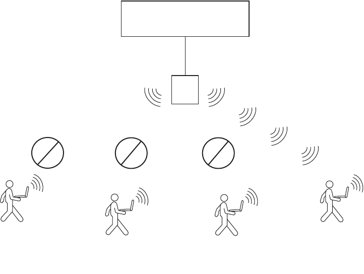
Configuring WPA 285
Figure 21 shows the client support when WPA encryption for TKIP only is
enabled. A radio using WPA with TKIP encrypts traffic only for WPA TKIP
clients but not for CCMP or WEP clients. The radio disassociates from
these other clients.
Figure 21 WPA Encryption with TKIP Only
Encryption settings:
-WPA enabled: TKIP only
-Dynamic WEP disabled
-Static WEP disabled
User D
TKIP
WPA
User C
Static WEP
Non-WPA
User B
Dynamic 40-bit WEP
WPA
User A
Dynamic WEP
Non-WPA
WX Switch
MAP
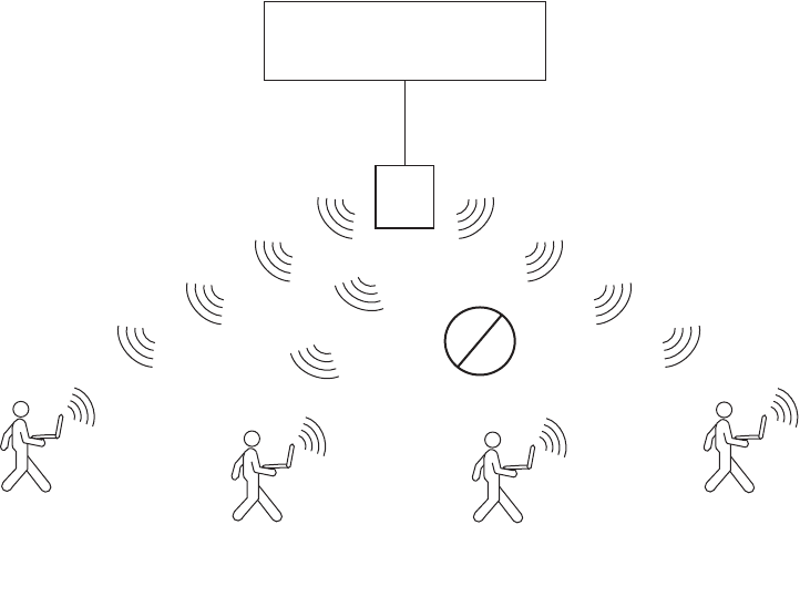
286 CHAPTER 13: CONFIGURING USER ENCRYPTION
Figure 22 shows the client support when both WEP encryption and TKIP
are enabled. A radio using WPA with TKIP and WEP encrypts traffic for
WPA TKIP clients, WPA WEP clients, and non-WPA dynamic WEP clients,
but not for CCMP or static WEP clients. The radio disassociates from
these other clients.
Figure 22 WPA Encryption with TKIP and WEP
User D
TKIP
WPA
User C
Static WEP
Non-WPA
User B
Dynamic 40-bit WEP
WPA
User A
Dynamic WEP
Non-WPA
Encryption settings:
-WPA enabled: TKIP, WEP40
-Dynamic WEP enabled
-Static WEP disabled
WX Switch
MAP
Configuring WPA 287
TKIP
Countermeasures
WPA access points and clients verify the integrity of a wireless frame
received on the network by generating a keyed message integrity check
(MIC). The Michael MIC used with TKIP provides a holddown mechanism
to protect the network against tampering.
If the recalculated MIC matches the MIC received with the frame, the
frame passes the integrity check and the access point or client
processes the frame normally.
If the recalculated MIC does not match the MIC received with the
frame, the frame fails the integrity check. This condition is called a
MIC failure. The access point or client discards the frame and also
starts a 60-second timer. If another MIC failure does not occur within
60 seconds, the timer expires. However, if another MIC failure occurs
before the timer expires, the device takes the following actions:
A MAP that receives another frame with an invalid MIC ends its
sessions with all TKIP and WEP clients by disassociating from the
clients. This includes both WPA WEP clients and non-WPA WEP
clients. The access point also temporarily shuts down the network
by refusing all association or reassociation requests from TKIP and
WEP clients. In addition, MSS generates an SNMP trap that
indicates the WX port and radio that received frames with the two
MIC failures as well as the source and destination MAC addresses
in the frames.
A client that receives another frame with an invalid MIC
disassociates from its access point and does not send or accept any
frames encrypted with TKIP or WEP.
The MAP or client refuses to send or receive traffic encrypted with
TKIP or WEP for the duration of the countermeasures timer, which is
60,000 milliseconds (60 seconds) by default. When the
countermeasures timer expires, the access point allows associations
and reassociations and generates new session keys for them. You can
set the countermeasures timer for MAP radios to a value from 0 to
60,000 milliseconds (ms). If you specify 0 ms, the radios do not use
countermeasures but instead continue to accept and forward
encrypted traffic following a second MIC failure. However, MSS still
generates an SNMP trap to inform you of the MIC failure.
The MIC used by CCMP, CBC-MAC, is even stronger than Michael and
does not require or provide countermeasures. WEP does not use a MIC.
Instead, WEP performs a cyclic redundancy check (CRC) on the frame and
generates an integrity check value (ICV).

288 CHAPTER 13: CONFIGURING USER ENCRYPTION
WPA Authentication
Methods
You can configure an SSID to support one or both of the following
authentication methods for WPA clients:
802.1X — The MAP and client use an Extensible Authentication
Protocol (EAP) method to authenticate one another, then use the
resulting key in a handshake to derive a unique key for the session.
The 802.1X authentication method requires user information to be
configured on AAA servers or in the WX switch’s local database. This is
the default WPA authentication method.
Preshared key (PSK) — A MAP radio and a client authenticate one
another based on a key that is statically configured on both devices.
The devices then use the key in a handshake to derive a unique key for
the session. For a given service profile, you can globally configure a
PSK for use with all clients. You can configure the key by entering an
ASCII passphrase or by entering the key itself in raw (hexadecimal)
form.
For a MAC client that authenticates using a PSK, the RADIUS servers or
local database still must contain an authentication rule for the client, to
assign the client to a VLAN.
MSS sets the timeout for the key exchanges between WPA (or RSN)
clients and the MAP to the same value as the last setting of the
retransmission timeout. The retransmission timeout is set to the lower of
the 802.1X supplicant timeout or the RADIUS session-timeout attribute.
See “Setting EAP Retransmission Attempts” on page 535 for more
information.
WPA Information
Element
A WPA information element (IE) is a set of extra fields in a wireless frame
that contain WPA information for the access point or client. To enable
WPA support in a service profile, you must enable the WPA IE. The
following types of wireless frames can contain a WPA IE:
Beacon (sent by a MAP) — The WPA IE in a beacon frame advertises
the cipher suites and authentication methods that a MAP radio
supports for the encrypted SSID. The WPA IE also lists the cipher suites
that the radio uses to encrypt broadcast and multicast frames. A MAP
radio always uses the least secure of the cipher suites to encrypt
broadcast and multicast frames to ensure that all clients associated
with the SSID can decrypt the frames. A MAP radio uses the most
secure cipher suite supported by both the radio and a client to encrypt
unicast traffic to that client.
Configuring WPA 289
Probe response (sent by a MAP radio) — The WPA IE in a probe
response frame lists the same WPA information that is contained in
the beacon frame.
Association request or reassociation (sent by a client) — The
WPA IE in an association request lists the authentication method and
cipher suite the client wants to use.
Client Support To use the TKIP or CCMP cipher suite for encryption, a client must
support WPA. However, a MAP radio configured for WPA can support
non-WPA clients who use dynamic WEP or static WEP. If the WPA IE is
enabled in the service profile used by an SSID supported by the radio, and
the 40-bit WEP or 104-bit WEP cipher suite also is enabled in the service
profile, MSS allows a non-WPA client to authenticate using WEP under
the following circumstances:
If a client wants to authenticate using dynamic WEP, MSS uses 802.1X
to authenticate the client if either the WEP40 or WEP104 cipher suite
is enabled for WPA.
If a client wants to authenticate using static WEP, the radio checks for
the static WEP key presented by the client. If the keys match, MSS
authenticates the client. Because the WEP key is static, MSS does not
use 802.1X to authenticate the client.
To allow a non-WPA client that uses dynamic WEP to be authenticated by
a radio on which WPA IE is enabled, enable the WEP40 or WEP104 cipher
suite in the service profile for the SSID the client will access. To prevent
non-WPA clients that use dynamic WEP from being authenticated, do not
enable the WEP40 or WEP104 cipher suite in the service profile.
To allow a client that uses static WEP to be authenticated, configure the
same WEP keys on the client and the service profile.

290 CHAPTER 13: CONFIGURING USER ENCRYPTION
Table 24 lists the encryption support for WPA and non-WPA clients.
Configuring WPA To configure MAP radios to support WPA:
1Create a service profile for each SSID that will support WPA clients.
2Enable the WPA IE in the service profile.
3Enable the cipher suites you want to support in the service profile. (TKIP is
enabled by default.) Optionally, you also can change the countermeasures
timer value for TKIP.
4Map the service profile to the radio profile that will control IEEE settings
for the radios.
5Assign the radio profile to the radios and enable the radios.
If you plan to use PSK authentication, you also need to enable this
authentication method and enter an ASCII passphrase or a hexadecimal
(raw) key.
Table 24 Encryption Support for WPA and Non-WPA Clients
MSS
Encryption
Type
Client Encryption Type
WPA —
CCMP
WPA —
TKIP
WPA —
WEP40
WPA —
WEP104
Dynamic
WEP
Static
WEP
WPA —
CCMP
Supports
WPA —
TKIP
Supports
WPA —
WEP40
Supports Supports
WPA —
WEP104
Supports Supports Supports
Dynamic
WEP
Supports
Static
WEP
Supports
Configuring WPA 291
Creating a Service Profile for WPA
Encryption parameters apply to all users who use the SSID configured by
a service profile. To create a service profile, use the following command:
set service-profile name
To create a new service profile named wpa, type the following command:
WX1200# set service-profile wpa
success: change accepted.
Enabling WPA
To enable WPA, you must enable the WPA information element (IE) in the
service profile. To enable the WPA IE, use the following command:
set service-profile name wpa-ie {enable | disable}
To enable WPA in service profile wpa, type the following command:
WX1200# set service-profile wpa wpa-ie enable
success: change accepted.
Specifying the WPA Cipher Suites
To use WPA, at least one cipher suite must be enabled. You can enable
one or more of the following cipher suites:
CCMP
TKIP
40-bit WEP
104-bit WEP
By default, TKIP is enabled and the other cipher suites are disabled.
To enable or disable cipher suites, use the following commands:
set service-profile name cipher-ccmp {enable |disable}
set service-profile name cipher-tkip {enable |disable}
set service-profile name cipher-wep104 {enable |disable}
set service-profile name cipher-wep40 {enable |disable}
To enable the 40-bit WEP cipher suite in service profile wpa, type the
following command:
WX1200# set service-profile wpa cipher-wep40 enable
success: change accepted.

292 CHAPTER 13: CONFIGURING USER ENCRYPTION
After you type this command, the service profile supports TKIP and 40-bit
WEP.
Microsoft Windows XP does not support WEP with WPA. To configure a
service profile to provide WEP for XP clients, leave WPA disabled and see
“Configuring WEP” on page 299.
Changing the TKIP Countermeasures Timer Value
By default, MSS enforces TKIP countermeasures for 60,000 ms (60
seconds) after a second MIC failure within a one-minute interval. To
change the countermeasures timer value, use the following command:
set service-profile name tkip-mc-time wait-time
To change the countermeasures wait time in service profile wpa to 30
seconds, type the following command:
WX1200# set service-profile wpa tkip-mc-time 30000
success: change accepted.
Enabling PSK Authentication
By default, WPA uses 802.1X dynamic keying. If you plan to use static
keys, you must enable PSK authentication and configure a passphrase or
the raw key. You can configure the passphrase or key globally. You also
can configure keys on an individual MAC client basis.
By default, 802.1X authentication remains enabled when you enable
PSK authentication.
To enable PSK authentication, use the following command:
set service-profile name auth-psk {enable |disable}
To enable PSK authentication in service profile wpa, type the following
command:
WX1200# set service-profile wpa auth-psk enable
success: change accepted.
Configuring a Global PSK Passphrase or Raw Key for All Clients
To configure a global passphrase for all WPA clients, use the following
command:
set service-profile name psk-phrase passphrase

Configuring WPA 293
The passphrase must be from 8 to 63 characters long, including blanks. If
you use blanks, you must enclose the string in quotation marks.
To configure service profile wpa to use passphrase
1234567890123<>?=+&% The quick brown fox jumps over the lazy sl,
type the following command:
WX1200# set service-profile wpa psk-phrase "1234567890123<>
?=+&% The quick brown fox jumps over the lazy sl"
success: change accepted.
As an alternative to entering a passphrase, which MSS converts into a
key, you can enter the key itself in raw hexadecimal format. To enter a
PSK key in raw format, use the following command:
set service-profile name psk-raw hex
For hex, type a 64-bit ASCII string representing a 32-digit hexadecimal
number. Enter the two-character ASCII form of each hexadecimal
number.
To configure service profile wpa to use a raw PSK with PSK clients, type a
command such as the following:
WX1200# set service-profile wpa psk-raw c25d3fe4483e867d1df96
eaacdf8b02451fa0836162e758100f5f6b87965e59d
success: change accepted.
Disabling 802.1X Authentication for WPA
To disable 802.1X authentication for WPA clients, use the following
command:
set service-profile name auth-dot1x {enable |disable}
This command does not disable 802.1X authentication for non-WPA
clients.
To disable WPA authentication in service profile wpa, type the following
command:
WX1200# set service-profile wpa auth-dot1x disable
success: change accepted.

294 CHAPTER 13: CONFIGURING USER ENCRYPTION
Displaying WPA Settings
To display the WPA settings in a service profile, use the following
command:
display service-profile {name | ?}
To display the WPA settings in effect in service profile wpa, type the
following command:
WX1200# display service-profile sp1
ssid-name: private ssid-type: crypto
Beacon: yes Proxy ARP: no
DHCP restrict: no No broadcast: no
Short retry limit: 5 Long retry limit: 5
Auth fallthru: none Sygate On-Demand (SODA): no
Enforce SODA checks: yes SODA remediation ACL:
Custom success web-page: Custom failure web-page:
Custom logout web-page: Custom agent-directory:
Static COS: no COS: 0
CAC mode: none CAC sessions: 14
User idle timeout: 180 Idle client probing: yes
Keep initial vlan: no Web Portal Session Timeout: 5
Web Portal ACL:
WEP Key 1 value: <none> WEP Key 2 value: <none>
WEP Key 3 value: <none> WEP Key 4 value: <none>
WEP Unicast Index: 1 WEP Multicast Index: 1
Shared Key Auth: NO
WPA enabled:
ciphers: cipher-tkip, cipher-wep40
authentication: 802.1X
TKIP countermeasures time: 30000ms
11a beacon rate: 6.0 multicast rate: AUTO
11a mandatory rate: 6.0,12.0,24.0 standard rates: 9.0,18.0,36.0,48.0,54.0
11b beacon rate: 2.0 multicast rate: AUTO
11b mandatory rate: 1.0,2.0 standard rates: 5.5,11.0
11g beacon rate: 2.0 multicast rate: AUTO
11g mandatory rate: 1.0,2.0,5.5,11.0 standard rates: 6.0,9.0,12.0,18.0,24.0,
36.0,48.0,54.0
The WPA settings appear at the bottom of the output.
The WPA fields appear in the display service-profile output only when
WPA is enabled.
Configuring WPA 295
Assigning the Service Profile to Radios and Enabling the Radios
After you configure WPA settings in a service profile, you can map the
service profile to a radio profile, assign the radio profile to radios, and
enable the radios to activate the settings.
To map a service profile to a radio profile, use the following command:
set radio-profile name service-profile name
To assign a radio profile to radios and enable the radios, use the following
command:
set ap port-list radio {1 | 2} radio-profile name
mode {enable |disable}
To map service profile wpa to radio profile bldg1, type the following
command:
WX1200# set radio-profile blgd1 service-profile wpa
success: change accepted.
To assign radio profile bldg1 to radio 1 on ports 1-3, and 5 and enable
the radios, type the following command:
WX1200# set ap 1-3,5 radio 1 radio-profile bldg1 mode enable
success: change accepted.
To assign radio profile bldg1 to radio 2 on ports 1-2 and port 6 and
enable the radios, type the following command:
WX1200# set ap 1-2,6 radio 2 radio-profile bldg1 mode enable
success: change accepted.

296 CHAPTER 13: CONFIGURING USER ENCRYPTION
Configuring RSN
(802.11i)
Robust Security Network (RSN) provides 802.11i support. RSN uses AES
encryption.
You can configure a service profile to support RSN clients exclusively, or to
support RSN with WPA clients, or even RSN, WPA and WEP clients.
The configuration tasks for a service profile to use RSN are similar to the
tasks for WPA:
1Create a service profile for each SSID that will support RSN clients.
2Enable the RSN IE in the service profile.
3Enable the cipher suites you want to support in the service profile. (TKIP is
enabled by default.) Optionally, you also can change the countermeasures
timer value for TKIP.
4Map the service profile to the radio profile that will control IEEE settings
for the radios.
5Assign the radio profile to the radios and enable the radios.
If you plan to use PSK authentication, you also need to enable this
authentication method and enter an ASCII passphrase or a hexadecimal
(raw) key.
Creating a Service
Profile for RSN
Encryption parameters apply to all users who use the SSID configured by
a service profile. To create a service profile, use the following command:
set service-profile name
To create a new service profile named rsn, type the following command:
WX1200# set service-profile rsn
success: change accepted.
Enabling RSN To enable RSN, you must enable the RSN information element (IE) in the
service profile. To enable the RSN IE, use the following command:
set service-profile name rsn-ie {enable | disable}
To enable RSN in service profile wpa, type the following command:
WX1200# set service-profile rsn rsn-ie enable
success: change accepted.

Configuring RSN (802.11i) 297
Specifying the RSN
Cipher Suites
To use RSN, at least one cipher suite must be enabled. You can enable
one or more of the following cipher suites:
CCMP
TKIP
40-bit WEP
104-bit WEP
By default, TKIP is enabled and the other cipher suites are disabled.
To enable or disable cipher suites, use the following commands:
set service-profile name cipher-ccmp {enable |disable}
set service-profile name cipher-tkip {enable |disable}
set service-profile name cipher-wep104 {enable |disable}
set service-profile name cipher-wep40 {enable |disable}
To enable the CCMP cipher suite in service profile rsn, type the following
command:
WX1200# set service-profile rsn cipher-ccmp enable
success: change accepted.
After you type this command, the service profile supports both TKIP and
CCMP.
Microsoft Windows XP does not support WEP with RSN. To configure a
service profile to provide WEP for XP clients, leave RSN disabled and see
“Configuring WEP” on page 299.

298 CHAPTER 13: CONFIGURING USER ENCRYPTION
Changing the TKIP
Countermeasures
Timer Value
To change the TKIP countermeasures timer, see “Changing the TKIP
Countermeasures Timer Value” on page 298. The procedure is the same
for WPA and RSN.
Enabling PSK
Authentication
To enable PSK authentication, see “Enabling PSK Authentication” on
page 298. The procedure is the same for WPA and RSN.
Displaying RSN
Settings
To display the RSN settings in a service profile, use the following
command:
display service-profile {name | ?}
The RSN settings appear at the bottom of the output.
RSN-related fields appear in the display service-profile output only
when RSN is enabled.
Assigning the Service
Profile to Radios and
Enabling the Radios
After you configure RSN settings in a service profile, you can map the
service profile to a radio profile, assign the radio profile to radios, and
enable the radios to activate the settings.
To map a service profile to a radio profile, use the following command:
set radio-profile name service-profile name
To assign a radio profile to radios and enable the radios, use the following
command:
set ap port-list radio {1 | 2} radio-profile name
mode {enable |disable}
To map service profile rsn to radio profile bldg2, type the following
command:
WX1200# set radio-profile blgd2 service-profile rsn
success: change accepted.

Configuring WEP 299
Configuring WEP Wired-Equivalent Privacy (WEP) is a security protocol defined in the
802.11 standard. WEP uses the RC4 encryption algorithm to encrypt
data.
To provide integrity checking, WEP access points and clients check the
integrity of a frame’s cyclic redundancy check (CRC), generate an integrity
check value (ICV), and append the value to the frame before sending it.
The radio or client that receives the frame recalculates the ICV and
compares the result to the ICV in the frame. If the values match, the
frame is processed. If the values do not match, the frame is discarded.
WEP is either dynamic or static depending on how the encryption keys
are generated. MAPs support dynamic WEP and static WEP.
For dynamic WEP, MSS dynamically generates keys for broadcast,
multicast, and unicast traffic. MSS generates unique unicast keys for
each client session and periodically regenerates (rotates) the broadcast
and multicast keys for all clients. You can change or disable the
broadcast or multicast rekeying interval.
For static WEP, MSS uses statically configured keys typed in the WX
switch’s configuration and on the wireless client and does not rotate
the keys.
Dynamic WEP encryption is enabled by default. You can disable dynamic
WEP support by enabling WPA and leaving the WEP-40 or WEP-104
cipher suites disabled. If you use dynamic WEP, 802.1X must also be
configured on the client in addition to WEP.
Static WEP encryption is disabled by default. To enable static WEP
encryption, configure the static WEP keys and assign them to unicast and
multicast traffic. Make sure you configure the same static keys on the
clients.
To support dynamic WEP in a WPA environment, enable WPA and enable
the WEP-40 or WEP-104 cipher suite. (See “Configuring WPA” on
page 290.)
This section describes how to configure and assign static WEP keys. (To
change other key-related settings, see “Managing 802.1X Encryption
Keys” on page 533.)
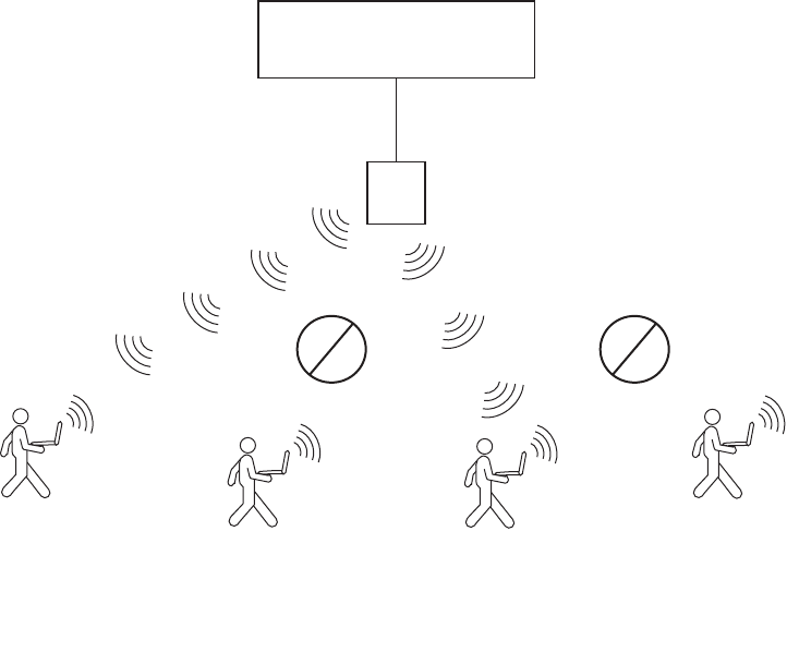
300 CHAPTER 13: CONFIGURING USER ENCRYPTION
Figure 23 shows an example of a radio configured to provide static and
dynamic WEP encryption for non-WPA clients. The radio uses dynamically
generated keys to encrypt traffic for dynamic WEP clients. The radio also
encrypts traffic for static WEP clients whose keys match the keys
configured on the radio.
Figure 23 Encryption for Dynamic and Static WEP
User D
TKIP
WPA
User C
Static WEP
-Unicast key = a1b1c1d1e1
-Multicast key = a2b2c2d2e2
Non-WPA
User B
Dynamic 40-bit WEP
WPA
User A
Dynamic WEP
Non-WPA
WPA disabled
Dynamic WEP enabled
Static WEP enabled
-Unicast key = a1b1c1d1e1
-Multicast key = a2b2c2d2e2
WX Switch
MAP
Configuring WEP 301
Setting Static WEP
Key Values
MSS supports dynamic WEP automatically. To enable static WEP,
configure WEP keys and assign them to unicast and multicast traffic. You
can set the values of the four static WEP keys, then specify which of the
keys to use for encrypting multicast frames and unicast frames. If you do
this, MSS continues to support dynamic WEP in addition to static WEP.
To set the value of a WEP key, use the following command:
set service-profile name wep key-index num key value
The key-index num parameter specifies the index you are configuring.
You can specify a value from 1 through 4.
The key value parameter specifies the hexadecimal value of the key. Type
a 10-character ASCII string (representing a 5-byte hexadecimal number)
or type a 26-character ASCII string (representing a 13-byte hexadecimal
number). You can use numbers or letters. ASCII characters in the
following ranges are supported:
0 to 9
A to F
a to f
To configure WEP key index 1 for radio profile rp1 to aabbccddee, type
the following command:
WX1200# set service-profile rp1 wep key-index 1 key
aabbccddee
success: change accepted.
Assigning Static WEP
Keys
When static WEP is enabled, static WEP key 1 is assigned to unicast and
multicast traffic by default. To assign another key to unicast or multicast
traffic, use the following commands:
set service-profile name wep active-multicast-index num
set service-profile name wep active-unicast-index num
The num parameter specifies the key and the value can be from 1 to 4.
To configure an SSID that uses service profile wepsrvc to use WEP key
index 2 for encrypting multicast traffic, type the following command:
WX1200# set service-profile wepsrvc wep
active-multicast-index 2
success: change accepted.

302 CHAPTER 13: CONFIGURING USER ENCRYPTION
To configure an SSID that uses service profile wepsrvc4 to use WEP key
index 4 for encrypting unicast traffic, type the following command:
WX1200# set service-profile wepsrvc4 wep
active-unicast-index 4
success: change accepted.
Encryption
Configuration
Scenarios
The following scenarios provide examples of ways in which you can
configure encryption for network clients:
“Enabling WPA with TKIP” on page 302
“Enabling Dynamic WEP in a WPA Network” on page 304
“Configuring Encryption for MAC Clients” on page 306
Enabling WPA with
TKIP
The following example shows how to configure MSS to provide
authentication and TKIP encryption for 801.X WPA clients. This example
assumes that pass-through authentication is used for all users. A RADIUS
server group performs all authentication and authorization for the users.
1Create an authentication rule that sends all 802.1X users of SSID mycorp
in the EXAMPLE domain to the server group shorebirds for
authentication. Type the following command:
WX1200# set authentication dot1x ssid mycorp EXAMPLE\*
pass-through shorebirds
2Create a service profile named wpa for the SSID. Type the following
command:
WX1200# set service-profile wpa
success: change accepted.
3Set the SSID in the service profile to mycorp. Type the following
command:
WX1200# set service-profile wpa ssid-name wpa
success: change accepted.
4Enable WPA in service profile wpa. Type the following command:
WX1200# set service-profile wpa wpa-ie enable
success: change accepted.
TKIP is already enabled by default when WPA is enabled.
5Display the service profile wpa to verify the changes. Type the following
command:
Encryption Configuration Scenarios 303
WX1200# display service-profile sp1
ssid-name: mycorp ssid-type: crypto
Beacon: yes Proxy ARP: no
DHCP restrict: no No broadcast: no
Short retry limit: 5 Long retry limit: 5
Auth fallthru: none Sygate On-Demand (SODA): no
Enforce SODA checks: yes SODA remediation ACL:
Custom success web-page: Custom failure web-page:
Custom logout web-page: Custom agent-directory:
Static COS: no COS: 0
CAC mode: none CAC sessions: 14
User idle timeout: 180 Idle client probing: yes
Keep initial vlan: no Web Portal Session Timeout: 5
Web Portal ACL:
Web Portal Session Timeout: 5
WEP Key 1 value: <none> WEP Key 2 value: <none>
WEP Key 3 value: <none> WEP Key 4 value: <none>
WEP Unicast Index: 1 WEP Multicast Index: 1
Shared Key Auth: NO
WPA enabled:
ciphers: cipher-tkip
authentication: 802.1X
TKIP countermeasures time: 60000ms
...
6Map service profile wpa to radio profile rp1. Type the following
commands:
WX1200# set radio-profile rp1 service-profile wpa
success: change accepted.
7Apply radio profile rp1 to radio 1 on port 5 and to radios 1 and 2 on port
6, enable the radios, and verify the configuration changes. Type the
following commands:
WX1200# set ap 5,6 radio 1 radio-profile rp1 mode enable
success: change accepted.
WX1200# set ap 6 radio 2 radio-profile rp1 mode enable
success: change accepted.
WX1200# display ap config
Port 5: AP model: mp-241, POE: enable, bias: high, name: MAP05
boot-download-enable: YES
force-image download: YES
Radio 1: type: 802.11a, mode: enabled, channel: 36
tx pwr: 1, profile: rp1
auto-tune max-power: default
Port 11: AP model: mp-252, POE: enable, bias: high, name: MAP11
boot-download-enable: YES
304 CHAPTER 13: CONFIGURING USER ENCRYPTION
force-image download: YES
Radio 1: type: 802.11g, mode: enabled, channel: 6
tx pwr: 1, profile: rp1
auto-tune max-power: default
Radio 2: type: 802.11a, mode: enabled, channel: 36
tx pwr: 1, profile: rp1
auto-tune max-power: default
8Save the configuration. Type the following command:
WX1200# save config
success: configuration saved.
Enabling Dynamic
WEP in a WPA
Network
The following example shows how to configure MSS to provide
authentication and encryption for 801.X dynamic WEP clients, and for
801.X WPA clients using TKIP. This example assumes that pass-through
authentication is used for all users. The commands are the same as those
in “Enabling WPA with TKIP” on page 302, with the addition of a
command to enable a WEP cipher suite. The WEP cipher suite allows
authentication and encryption for both WPA and non-WPA clients that
want to authenticate using dynamic WEP.
1Create an authentication rule that sends all 802.1X users of SSID mycorp
in the EXAMPLE domain to the server group shorebirds for
authentication. Type the following command:
WX1200# set authentication dot1x ssid thiscorp EXAMPLE\*
pass-through shorebirds
2Create a service profile named wpa-wep for the SSID. Type the following
command:
WX1200# set service-profile wpa-wep
success: change accepted.
3Set the SSID in the service profile to thiscorp. Type the following
command:
WX1200# set service-profile wpa-wep ssid-name thiscorp
success: change accepted.
4Enable WPA in service profile wpa-wep. Type the following command:
WX1200# set service-profile wpa-wep wpa-ie enable
success: change accepted.
5Enable the WEP40 cipher suite in service profile wpa-wep. Type the
following command:
WX1200# set service-profile wpa-wep cipher-wep40 enable
success: change accepted.
Encryption Configuration Scenarios 305
TKIP is already enabled by default when WPA is enabled.
6Display the service profile wpa-wep to verify the changes. Type the
following command:
WX1200# display service-profile sp1
ssid-name: mycorp ssid-type: crypto
Beacon: yes Proxy ARP: no
DHCP restrict: no No broadcast: no
Short retry limit: 5 Long retry limit: 5
Auth fallthru: none Sygate On-Demand (SODA): no
Enforce SODA checks: yes SODA remediation ACL:
Custom success web-page: Custom failure web-page:
Custom logout web-page: Custom agent-directory:
Static COS: no COS: 0
CAC mode: none CAC sessions: 14
User idle timeout: 180 Idle client probing: yes
Keep initial vlan: no Web Portal Session Timeout: 5
Web Portal ACL:
WEP Key 1 value: <none> WEP Key 2 value: <none>
WEP Key 3 value: <none> WEP Key 4 value: <none>
WEP Unicast Index: 1 WEP Multicast Index: 1
Shared Key Auth: NO
WPA enabled:
ciphers: cipher-tkip, cipher-wep40
authentication: 802.1X
TKIP countermeasures time: 60000ms
...
7Map service profile wpa-wep to radio profile rp2. Type the following
commands:
WX1200# set radio-profile rp2 service-profile wpa-wep
success: change accepted.
8Apply radio profile rp2 to radio 1 on port 5 and to radios 1 and 2 on
port 6, enable the radios, and verify the configuration changes. Type the
following commands:
WX1200# set ap 5,6 radio 1 radio-profile rp2 mode enable
success: change accepted.
WX1200# set ap 6 radio 2 radio-profile rp2 mode enable
success: change accepted.
WX1200# display ap config
Port 5: AP model: mp-241, POE: enable, bias: high, name: MAP05
boot-download-enable: YES
force-image-download: YES
Radio 1: type: 802.11a, mode: enabled, channel: 36
tx pwr: 1, profile: rp2
306 CHAPTER 13: CONFIGURING USER ENCRYPTION
auto-tune max-power: default
Port 6: AP model: mp-252, POE: enable, bias: high, name: MAP11
boot-download-enable: YES
force-image-download: YES
Radio 1: type: 802.11g, mode: enabled, channel: 6
tx pwr: 1, profile: rp2
auto-tune max-power: default
Port 11: AP model: mp-252, POE: enable, bias: high, name: MP11
boot-download-enable: YES
force-image-download: YES
Radio 1: type: 802.11g, mode: enabled, channel: 6
tx pwr: 1, profile: rp2
auto-tune max-power: default
Radio 2: type: 802.11a, mode: enabled, channel: 36
tx pwr: 1, profile: rp2
auto-tune max-power: default
9Save the configuration. Type the following command:
WX1200# save config
success: configuration saved.
Configuring
Encryption for MAC
Clients
The following example shows how to configure MSS to provide PSK
authentication and TKIP or 40-bit WEP encryption for MAC clients:
1Create an authentication rule that sends all MAC users of SSID voice to
the local database for authentication and authorization. Type the
following command:
WX1200# set authentication mac ssid voice * local
success: configuration saved.
2Configure a MAC user group named wpa-for-mac that assigns all MAC
users in the group to VLAN blue. Type the following command:
WX1200# set mac-usergroup wpa-for-mac attr vlan-name blue
success: configuration saved.
3Add MAC users to MAC user group wpa-for-mac. Type the following commands:
WX1200# set mac-user aa:bb:cc:dd:ee:ff group wpa-for-mac
success: configuration saved.
WX1200# set mac-user a1:b1:c1:d1:e1:f1 group wpa-for-mac
success: configuration saved.
Encryption Configuration Scenarios 307
4Verify the AAA configuration changes. Type the following command:
WX1200# display aaa
Default Values
authport=1812 acctport=1813 timeout=5 acct-timeout=5
retrans=3 deadtime=0 key=(null) author-pass=(null)
Radius Servers
Server Addr Ports T/o Tries Dead State
-------------------------------------------------------------------
Server groups
set authentication mac ssid voice * local
mac-usergroup wpa-for-mac
vlan-name = blue
mac-user aa:bb:cc:dd:ee:ff
Group = wpa-for-mac
mac-user a1:b1:c1:d1:e1:f1
Group = wpa-for-mac
5Create a service profile named wpa-wep-for-mac for SSID voice. Type the
following command:
WX1200# set service-profile wpa-wep-for-mac
success: change accepted.
6Set the SSID in the service profile to voice. Type the following command:
WX1200# set service-profile wpa-wep-for-mac ssid-name voice
success: change accepted.
7Enable WPA in service profile wpa-wep-for-mac. Type the following
command:
WX1200# set service-profile wpa-wep-for-mac wpa-ie enable
success: change accepted.
8Enable the WEP40 cipher suite in service profile wpa-wep-for-mac. Type
the following command:
WX1200# set service-profile wpa-wep-for-mac
cipher-wep40 enable
success: change accepted.
TKIP is already enabled by default when WPA is enabled.
9Enable PSK authentication in service profile wpa-wep-for-mac. Type the
following command:
WX1200# set service-profile wpa-wep-for-mac auth-psk enable
success: change accepted.
308 CHAPTER 13: CONFIGURING USER ENCRYPTION
10 Configure a passphrase for the preshared key. Type the following
command:
WX1200# set service-profile wpa-wep-for-mac psk-phrase
"passphrase to convert into a preshared key"
success: change accepted.
11 Display the WPA configuration changes. Type the following command:
WX1200# display service-profile sp1
ssid-name: voice ssid-type: crypto
Beacon: yes Proxy ARP: no
DHCP restrict: no No broadcast: no
Short retry limit: 5 Long retry limit: 5
Auth fallthru: none Sygate On-Demand (SODA): no
Enforce SODA checks: yes SODA remediation ACL:
Custom success web-page: Custom failure web-page:
Custom logout web-page: Custom agent-directory:
Static COS: no COS: 0
CAC mode: none CAC sessions: 14
User idle timeout: 180 Idle client probing: yes
Keep initial vlan: no Web Portal Session Timeout: 5
Web Portal ACL:
WEP Key 1 value: <none> WEP Key 2 value: <none>
WEP Key 3 value: <none> WEP Key 4 value: <none>
WEP Unicast Index: 1 WEP Multicast Index: 1
Shared Key Auth: NO
WPA enabled:
12 Map service profile wpa-wep-for-mac to radio profile rp3. Type the
following commands:
WX1200# set radio-profile rp3 service-profile wpa-wep-for-mac
success: change accepted.
13 Apply radio profile rp3 to radio 1 on port 4 and to radios 1 and 2 on port
6 and enable the radios, and verify the configuration changes. Type the
following commands:
WX1200# set ap 4,6 radio 1 radio-profile rp3 mode enable
success: change accepted.
WX1200# set ap 6 radio 2 radio-profile rp3 mode enable
success: change accepted.
Encryption Configuration Scenarios 309
WX1200# display ap config
Port 4: AP model: MP-241, POE: enable, bias: high, name: MAP04
boot-download-enable: YES
force-image-download: YES
Radio 1: type: 802.11a, mode: enabled, channel: 36
tx pwr: 1, profile: rp3
auto-tune max-power: default
Port 6: AP model: mp-252, POE: enable, bias: high, name: MAP06
boot-download-enable: YES
force-image-download: YES
Radio 1: type: 802.11g, mode: enabled, channel: 6
tx pwr: 1, profile: rp3
auto-tune max-power: default
Radio 2: type: 802.11a, mode: enabled, channel: 36
tx pwr: 1, profile: rp3
auto-tune max-power: default, min-client-rate: 24, max-retransmissions: 10
14 Save the configuration. Type the following command:
WX1200# save config
success: configuration saved.
310 CHAPTER 13: CONFIGURING USER ENCRYPTION

14 CONFIGURING RF AUTO-TUNING
The RF Auto-Tuning feature dynamically assigns channel and power
settings to MAP radios, and adjusts those settings when needed.
Overview RF Auto-Tuning can perform the following tasks:
Assign initial channel and power settings when a MAP radio is started.
Periodically assess the RF environment and change the channel or
power setting if needed.
By default, RF Auto-Tuning is enabled for channel configuration and
disabled for power configuration.
Initial Channel and
Power Assignment
The following process is used to assign the channel and power to a MAP
radio when it is first enabled:
If RF Auto-Tuning is disabled for both channel and power assignment,
the radio uses the channel and power settings in the radio profile that
manages the radio. After this, the channel and power do not change
unless you change the settings in the radio profile, or enable
RF Auto-Tuning.
If RF Auto-Tuning is enabled for channel and power assignment, the
radio performs an RF scan and reports the results to the WX switch
that is managing the MAP the radio is on. The scan results include
third-party access points. Based on the scan results, MSS sets the
channel and power on the radio. MSS always selects channel and
power settings that are valid for the country of operation.
Initial channel assignment—MSS selects a channel at random
from the set of valid channels for the radio type and country code.
After this, each subsequent time the radio or RF Auto-Tuning is
restarted, a different channel is selected to ensure even distribution
among the channels.
312 CHAPTER 14: CONFIGURING RF AUTO-TUNING
During radio operation, MSS periodically reevaluates the channel
and changes it if needed. (See “Channel Tuning” on page 313.)
Initial power assignment—The MAP sets a radio’s initial power
level to the maximum value allowed for the country code
(regulatory domain). In a deployment with few MAPs, the radio
remains at maximum power. Otherwise, the radio reduces power
until the power is just enough to reach the MAP’s nearest neighbor
that is on the same channel.
How Channels Are Selected
When a radio first comes up, if RF Auto-Tuning for channels is enabled,
the initial channel selected will follow a uniform distribution of channels
that spans the list of channels, rather than selecting the next sequential
channel number.
For example, the range of valid channels for 802.11a radios in the US is
as follows:
36, 40, 44, 48, 149, 153, 157, 161
On each WX, the first channel chosen will be random. Assuming that
channel 60 is the first channel selected, the order of the channel
selections will be as follows:
After these initial 8 channel selections are chosen, the pattern will repeat
itself.
Channel and Power
Tuning
RF Auto-Tuning can change the channel or power of a radio, to
compensate for RF changes such as interference, or to maintain at least
the minimum data transmit rate for associated clients. A radio continues
to scan on its active data channel and on other channels and reports the
results to its WX switch.
Periodically, the switch examines these results to determine whether the
channel or the power needs to be changed.
Order:25836147
Channel: 40 44 48 52 56 60 64 68
Overview 313
Power Tuning
By default, the switch evaluates the scan results for possible power
changes every 300 seconds (5 minutes), and raises or lowers the power
level if needed.
If RF Auto-Tuning determines that a power change is needed on a radio,
MSS ramps the power up or down until the new power level is reached.
Ramp-up or ramp-down of the power occurs in 1 dBm increments, at regular
time intervals. The default interval is 60 seconds and is configurable. The
power ramp amount (1 dBm per interval) is not configurable.
Channel Tuning
By default, the switch evaluates the scan results for possible channel
changes every 3600 seconds (1 hour). MSS uses the following parameters
to determine whether to change the channel on a radio:
Presence of active sessions.
By default, If the radio has active sessions, MSS does not change the
channel. If the radio does not have any active sessions, MSS uses the
remaining parameters to determine whether to change the channel.
Received signal strength indication (RSSI)
Amount of noise on the channel
Packet retransmission count, which is the rate at which the radio
receives retransmitted packets.
Utilization, calculated based on the number of multicast packets per
second that a radio can send on a channel while continuously sending
fixed-size frames over a period of time.
Phy error count, which is the number of frames received by the MAP
radio that have physical layer errors. A high number of Phy errors can
indicate the presence of a non-802.11 device using the same RF
spectrum.
Received CRC error count. A high number of CRC errors can indicate
a hidden node or co-channel interference.
The thresholds for these parameters are not configurable.
RF Auto-Tuning also can change a radio’s channel when the channel
tuning interval expires, if a channel that has less disturbance is detected.
Disturbance is based on the number of neighbors the radio has and each
neighbor’s RSSI.

314 CHAPTER 14: CONFIGURING RF AUTO-TUNING
A radio also can change its channel before the channel tuning interval expires
to respond to RF anomalies. An RF anomaly is a sudden major change in the
RF environment, such as sudden major interference on the channel.
By default, a radio cannot change its channel more often than every 900
seconds, regardless of the RF environment. This channel holddown avoids
unnecessary changes due to very transient RF changes, such as activation
of a microwave oven.
Tuning the Transmit Data Rate
A radio sends beacons, probe requests, and probe responses at the
minimum transmit data rate allowed for clients. This gives them the
maximum distance. All other packets are transmitted at a rate
determined by their destination. All packets are transmitted at the same
power level.
By default, the following minimum data rates are allowed:
5.5 Mbps for 802.11b/g clients
24 Mbps for 802.11a clients
You can statically change the transmit data rates for radios, on a radio
profile basis. (For information, see “Changing Transmit Rates” on
page 235). However, RF Auto-Tuning does not change transmit rates
automatically.
RF Auto-Tuning
Parameters
Table 25 lists the RF Auto-Tuning parameters and their default settings.
Table 25 Defaults for RF Auto-Tuning Parameters
Parameter Default Value
Radio Behavior When Parameter Set
to Default Value
Radio profile parameters
channel-config enable When the radio is first enabled,
RF Auto-Tuning sets the channel based
on the channels in use on neighboring
access points.
channel-interval 3600 Every 3600 seconds, MSS examines the
RF information gathered from the
network and determines whether the
channel needs to be changed to
compensate for RF changes.

Overview 315
channel-holddown 900 MSS maintains the channel setting on a
radio for at least 900 seconds regardless
of RF changes.
channel-lockdown disabled MSS continues to dynamically change
channels if needed based on network
conditions.
power-config disable MSS uses the highest power level
allowed for the country of operation or
the highest supported by the hardware,
whichever is lower.
power-interval 600 Every 600 seconds, MSS examines the RF
information gathered from the network
and determines whether the power
needs to be changed to compensate for
RF changes.
power-lockdown disabled MSS continues to dynamically change
power settings if needed based on
network conditions.
power-ramp-interval 60 When RF Auto-Tuning determines that
power should be increased or decreased,
MSS changes the power by 1 dBm every
60 seconds until the power setting is
reached..
Individual radio parameters
max-power Maximum
allowed for
country of
operation
RF Auto-Tuning never sets a radio’s
power to a level that is higher than the
maximum allowed for the country of
operation (countrycode).
Table 25 Defaults for RF Auto-Tuning Parameters (continued)
Parameter Default Value
Radio Behavior When Parameter Set
to Default Value

316 CHAPTER 14: CONFIGURING RF AUTO-TUNING
Changing
RF Auto-Tuning
Settings
You can change the following RF Auto-Tuning settings:
Channel tuning
Power tuning
Minimum transport data rate
Selecting Available
Channels on the
802.11a Radio
You can configure the 802.11a radio on a MAP to allow certain channels
to be available or unavailable. To enable this feature, use the following
command:
set radio-profile name auto-tune 11a-channel-range
{lower-bands | all bands}
If you select lower-bands, MSS selects a channel from the lower eight
bands in the 802.11a range of channels: 36, 40, 44, 48, 52, 56, 60, or
64.
If you select all-bands, MSS selects a channel from the entire 802.11a
range of channels: 36, 40, 44, 48, 52, 60, 64, 149, 153, 157, or 161.
Changing Channel
Tuning Settings
Disabling or Reenabling Channel Tuning
RF Auto-Tuning for channels is enabled by default. To disable or reenable
the feature for all radios in a radio profile, use the following command:
set radio-profile name auto-tune channel-config
{enable | disable} [ignore-clients]
The ignore-clients option allows MSS to change the channel on a radio
even if the radio has active client sessions. Without this option, MSS does
not change the channel unless there are no active client sessions on the
radio.
To disable channel tuning for radios in the rp2 radio profile, type the
following command:
WX1200# set radio-profile rp2 auto-tune channel-config
disable
success: change accepted.
Changing RF Auto-Tuning Settings 317
Changing the Channel Tuning Interval
The default channel tuning interval is 3600 seconds. You can change the
interval to a value from 0 to 65535 seconds. If you set the interval to 0,
RF Auto-Tuning does not reevaluate the channel at regular intervals.
However, RF Auto-Tuning can still change the channel in response to RF
anomalies. 3Com recommends that you use an interval of at least 300
seconds (5 minutes).
To change the channel tuning interval, use the following command:
set radio-profile name auto-tune channel-interval seconds
To set the channel tuning interval for radios in radio profile rp2 to 2700
seconds (45 minutes), type the following command:
WX1200# set radio-profile rp2 auto-tune channel-interval 2700
success: change accepted.
Changing the Channel Holddown Interval
The default channel holddown interval is 900 seconds. You can change
the interval to a value from 0 to 65535 seconds. To change the channel
holddown interval, use the following command:
set radio-profile name auto-tune channel-holddown holddown
To change the channel holddown for radios in radio profile rp2 to 600
seconds, type the following command:
WX1200# set radio-profile rp2 auto-tune channel-holddown 600
success: change accepted.
Changing Power
Tuning Settings
Enabling Power Tuning
RF Auto-Tuning for power is disabled by default. To enable or disable the
feature for all radios in a radio profile, use the following command:
set radio-profile name auto-tune
power-config {enable |disable}
To enable power tuning for radios in the rp2 radio profile, type the
following command:
WX1200# set radio-profile rp2 auto-tune power-config enable
success: change accepted.

318 CHAPTER 14: CONFIGURING RF AUTO-TUNING
Changing the Power Tuning Interval
The default power tuning interval is 600 seconds. You can change the
interval to a value from 1 to 65535 seconds. To change the power tuning
interval, use the following command:
set radio-profile name auto-tune power-interval seconds
To set the power tuning interval for radios in radio profile rp2 to 240
seconds, type the following command:
WX1200# set radio-profile rp2 auto-tune power-interval 240
success: change accepted.
Changing the Maximum Default Power Allowed On a Radio
By default, the maximum power level that RF Auto-Tuning can set on a
radio is the same as the maximum power level allowed for the country of
operation. To change the maximum power level that RF Auto-Tuning can
assign, use the following command:
set ap apnumber radio {1 | 2} auto-tune max-power power-level
The power-level can be a value from 1 to 20.
To set the maximum power that RF Auto-Tuning can set on radio 1 on
the MAP on port 6 to 12 dBm, type the following command.
WX1200# set ap 6 radio 1 auto-tune max-power 12
success: change accepted.
Locking Down
Tuned Settings
You can convert dynamically assigned channels and power settings into
statically configured settings, by locking them down. When you lock
down channel or power settings, MSS converts the latest values set by RF
Auto-Tuning into static settings.
You can lock down channel or power settings on a radio-profile basis.
MSS implements the lock down by changing the set {ap | dap} radio
channel or set {ap | dap} radio tx-power command for each radio
managed by the radio profile.
To lock down channel or power settings, use the following commands:
set radio-profile name auto-tune channel-lockdown
set radio-profile name auto-tune power-lockdown

Displaying RF Auto-Tuning Information 319
To verify the static settings, use the display {ap | dap} config command.
To save the locked down settings, you must save the switch’s configuration.
The following commands lock down the channel and power settings for
radios in radio profile rp2:
WX1200# set radio-profile rp2 auto-tune channel-lockdown
success: change accepted.
WX1200# set radio-profile rp2 auto-tune power-lockdown
success: change accepted.
Displaying
RF Auto-Tuning
Information
You can display the RF Auto-Tuning configuration, a list of RF neighbors,
and the values of RF attributes.
(For information about the fields in the output, see the Wireless LAN
Switch and Controller Command Reference.)
Displaying
RF Auto-Tuning
Settings
To display the RF Auto-Tuning settings that you can configure in a radio
profile, use the following command:
display radio-profile {name | ?}
Entering display radio-profile ? displays a list of radio profiles.
To display the RF Auto-Tuning and other settings in the default radio
profile, type the following command:
WX# display radio-profile default
Beacon Interval: 100 DTIM Interval: 1
Max Tx Lifetime: 2000 Max Rx Lifetime: 2000
RTS Threshold: 2346 Frag Threshold: 2346
Long Preamble: no Tune Channel: yes
Tune Channel Range (11a): lower-bands Ignore Clients: no
Tune Power: no Tune Channel Interval: 3600
Tune Power Interval: 600 Power ramp interval: 60
Channel Holddown: 300 Countermeasures: none
Active-Scan: yes RFID enabled: no
WMM Powersave: no QoS Mode: wmm
Rate Enforcement: no Initial Load: 1000
ETT Link Factor: 3 Change Threshold: 25
Dwell Time: 3600 Probe Interval: 60
Intial Measur Interval: 60 Maximum Measure Interval: 600
Radio Link Timeout: 5
320 CHAPTER 14: CONFIGURING RF AUTO-TUNING
To display the RF Auto-Tuning settings that you can configure on an
individual radio, use the following commands:
display ap config [port-list [radio {1 | 2}]]
display ap config [ap-num [radio {1 | 2}]]
To display the RF Auto-Tuning and other individual radio settings on radio
1 of a directly connected MAP connected to WX port 2, type the
following command:
WX# display ap config 2 radio 1
Port 2: AP model: mp-352, POE: enabled, bias: high, name:
MAP02
boot-downloaded-enable: YES
force-image-download: NO
Radio 1: type: 802.11g, mode: disabled, channel: 5
tx pwr: 1, profile: default
auto-tune max-power: default
To display the RF Auto-Tuning and other individual radio settings on both
radios on the MAP access point configured on connection 1, type the
following command:
WX# display ap config 1
Dap 1: serial-id: 12345678, AP model: mp-352, bias: high, name: DAP01
fingerprint: b4:f9:2a:52:37:58:f4:d0:10:75:43:2f:45:c9:52:c3
boot-download-enable: YES
force-image-download: NO
Radio 1: type: 802.11g, mode: disabled, channel: 6
tx pwr: 1, profile: default
auto-tune max-power: default
Radio 2: type: 802.11a, mode: disabled, channel: 36
tx pwr: 1, profile: default
auto-tune max-power: default
Displaying RF
Neighbors
To display the other radios that a specific 3Com radio can hear, use the
following commands:
display auto-tune neighbors [ap map-num [radio {1|2|all}]]
display auto-tune neighbors
[ap ap-num [radio {1|2|all}]
The list of radios includes beaconed third-party SSIDs, and both beaconed
and unbeaconed 3Com SSIDs.
Displaying RF Auto-Tuning Information 321
To display neighbor information for radio 1 on the directly connected
MAP on port 2, type the following command:
WX1200# display auto-tune neighbors ap 2 radio 1
Total number of entries for port 2 radio 1: 5
Channel Neighbor BSS/MAC RSSI
------- ----------------- ----
1 00:0b:85:06:e3:60 -46
1 00:0b:0e:00:0a:80 -78
1 00:0b:0e:00:d2:c0 -74
1 00:0b:85:06:dd:00 -50
1 00:0b:0e:00:05:c1 -72
Displaying RF
Attributes
To display the current values of the RF attributes RF Auto-Tuning uses to
decide whether to change channel or power settings, use the following
commands:
display auto-tune attributes
[ap map-num [radio {1|2|all}]]
display auto-tune attributes
[ap ap-num [radio {1|2|all}]]
To display RF attribute information for radio 1 on the directly connected
MAP on port 2, type the following command:
WX1200# display auto-tune attributes ap 2 radio 1
Auto-tune attributes for port 2 radio 1:
Noise: -92 Packet Retransmission
Count: 0
Utilization: 0 Phy Errors
Count: 0
CRC Errors count: 122
322 CHAPTER 14: CONFIGURING RF AUTO-TUNING

15
CONFIGURING MAPS TO BE
AEROSCOUT LISTENERS
AeroScout RFID tags are wireless transmitters that you can place on assets
such as office equipment to track the equipment’s location. Each tag
regularly transmits its unique ID. AeroScout listeners detect the
transmissions from the RFID tags and relay this information to an
AeroScout Engine or a WX. You can use an AeroScout Engine or 3Com
Wireless Switch Manager to locate the asset.
MAPs can be configured as AeroScout listeners. A MAP configured to be
an AeroScout listener detects RFID tag IDs and sends the tag information
to the WX switch managing the MAP. If an AeroScout Engine is
configured to request the information from the MAP, the MAP also sends
the information to the AeroScout Engine.
The accuracy of the location information depends on the number of
listeners (MAPs). 3Com recommends that you configure at least three
listeners.
You can configure Distributed MAPs or directly connected MAPs to listen
for RFID tags. However, if you plan to use an AeroScout Engine to display
asset locations, you must use Distributed MAPs. RFID tag information
from directly connected MAPs is available only to 3Com Wireless Switch
Manager.
15

324 CHAPTER 15: CONFIGURING MAPS TO BE AEROSCOUT LISTENERS
Configuring MAP
Radios to Listen for
AeroScout RFID
Tags
To configure MAP radios to listen for AeroScout RFID tags:
Configure a service profile for the AeroScout listeners and set the SSID
type to clear (unencrypted).
Configure a radio profile for the AeroScout listeners.
Disable RF Auto-Tuning of channels on the radio profile. Channels on
RFID tags are statically configured. Therefore, the listener should not
dynamically change channels.
Disable active scan on the radio profile. When active scan is enabled,
radios go off-channel for brief intervals to scan for rogues.
Enable RFID mode on the radio profile. RFID mode allows MAP radios
to accept Aeroscout Engine commands. A MAP will forward RFID tags
to an Aeroscout Engine after receiving an Enable Access Point
command from the Aeroscout Engine.
Map the AeroScout listeners’ service profile to the radio profile.
Set the channel on each radio to the channel on which the RFID tags
transmit. You can use the same channel on all the RFID tags.
Map the MAP radios to the radio profile and enable the radios.
A MAP always forwards RFID tag information to its WX switch, even if
RFID mode is disabled.
The following example shows the commands to configure three MAPs to
be AeroScout listeners. This example assumes that the MAPs have already
been installed and configured.
WX1200# set service-profile rfid-listeners ssid-type clear
success: change accepted.
WX1200# set radio-profile rfid-listeners active-scan disable
success: change accepted.
WX1200# set radio-profile rfid-listeners auto-tune channel-config disable
success: change accepted.
WX1200# set radio-profile rfid-listeners rfid-mode enable
success: change accepted.
WX1200# set radio-profile rfid-listeners service-profile rfid-listeners
success: change accepted.
WX1200# set ap 67 radio 1 channel 7
success: change accepted.
WX1200# set ap 68 radio 1 channel 7
success: change accepted.

Locating an RFID Tag 325
WX1200# set ap 69 radio 1 channel 7
success: change accepted.
WX1200# set ap 67 radio 1 radio-profile rfid-listeners mode enable
success: change accepted.
WX1200# set ap 68 radio 1 radio-profile rfid-listeners mode enable
success: change accepted.
WX1200# set ap 69 radio 1 radio-profile rfid-listeners mode enable
success: change accepted.
Locating an RFID Tag You can use an AeroScout Engine or 3Com Wireless Switch Manager to
locate an asset to which an RFID tag is attached.
Using an AeroScout
Engine
1Load the site map in AeroScout System Manager.
2Mark the origin point (0,0), if not already done.
3Calibrate distance, if not already done.
4Add each MAP configured as a listener to the map, and enter its IP
address.
To look up a Distributed MAP IP address, use the display ap status
command.
5Enable RSSI location calculation.
6Enable tag positioning.
7Enable the map to use the MAPs.
To check the status of a MAP, right-click on the MAP icon and select
Status.
Using 3Com Wireless
Switch Manager
If your network is modeled in a 3Com Wireless Switch Manager network
plan, you can use 3Com Wireless Switch Manager to locate devices that
have AeroScout asset tags. This capability requires the following:
Three or more listeners are required for optimal location results. 3Com
Wireless Switch Manager will attempt to display a tag’s location even if
there are fewer than three listeners, but the location might not be accurate.
The listener MAPs must be in the network plan, on the floor where
the asset tags are located.
326 CHAPTER 15: CONFIGURING MAPS TO BE AEROSCOUT LISTENERS
1Connect to 3Com Wireless Switch Manager Services (the server) and
open the network plan that contains the site information.
2Select the Monitor tool bar option (at the top of the main 3Com Wireless
Switch Manager window). The Monitor dashboard appears.
3Under the Clients graph, click Details.
4In the Manage menu of the Task List panel, select Find AeroScout Tag.
The Find AeroScout Tags dialog appears.
5Enter the search criteria:
aSelect Find all AeroScout Tags, or leave Find a specific AeroScout
Tag selected and type the MAC address of the asset tag.
bSelect the search scope.
6Click Next. A list of asset tags appears.
7To locate an asset:
aSelect its tag in the list.
bSelect Locate AeroScout Tag.
A picture of the floor plan where the tag is located appears. The likely
location of the asset is indicated.

16 CONFIGURING QUALITY OF
SERVICE
This chapter describes the Quality of Service (QoS) features supported in
MSS and how to configure and manage them.
About QoS MSS supports Layer 2 and Layer 3 classification and marking of traffic,
and optimized forwarding of wireless traffic for time-sensitive
applications such as voice and video.
Summary of QoS
Features
QoS features are configured in radio profiles and service profiles.
Table 26 lists the QoS features in MSS.
Table 26 QoS Parameters
QoS Feature Description Configuration Command
QoS parameters configured in the radio profile
QoS mode Method used to classify and mark
traffic, and to select forwarding
queues on MAPs. One of the
following modes can be enabled:
SpectraLink Voice Priority
Voice-Extension, for NEC handsets
(the default)
Wi-Fi Multimedia
set radio-profile qos-mode
See the following:
“QoS Mode” on page 330
“Changing the QoS Mode”
on page 342
WMM powersave
support Unscheduled Automatic Powersave
Delivery (U-APSD). U-APSD enables
clients that use powersave mode
to more efficiently request
buffered unicast packets from
MAP radios.
set radio-profile
wmm-powersave

328 CHAPTER 16: CONFIGURING QUALITY OF SERVICE
QoS parameters configured in service profiles
CAC mode Call Admission Control, which
regulates addition of new VoIP
sessions on MAP radios. One of
the following modes can be
enabled:
None (the default)
Session-based
set service-profile cac-mode
See the following:
“Call Admission Control” on
page 340
“Configuring Call Admission
Control” on page 343
Static CoS Simple CoS assignment. When
enabled, static CoS assigns the
same CoS value to all traffic on the
service profile’s SSID. Static CoS is
disabled by default.
The default static CoS value is 0.
set service-profile static-cos
set service-profile cos
See the following:
“Static CoS” on page 341
“Configuring Static CoS” on
page 343
Using client DSCP
value Whether MSS classifies the QoS
level of IP packets based on their
DSCP value, instead of their
802.11 priority.
set service-profile
use-client-dscp
See “Using the Client’s DSCP
Value to Classify QoS Level” on
page 344.
Table 26 QoS Parameters (continued)
QoS Feature Description Configuration Command

About QoS 329
Transmit rates Data transmission rates supported
by each radio type. The following
categories are specified:
Beacon
Multicast
Mandatory (a client must
support at least one of these
rates to associate)
Disabled
Standard (valid rates that are
not disabled and are not
mandatory)
Defaults:
Mandatory:
- 802.11a—6.0, 12.0, 24.0
- 802.11b—5.5, 11.0
- 802.11g—1.0, 2.0, 5.5, 11.0
Disabled—None. All rates
applicable to the radio type are
supported by default.
Beacon:
- 802.11a—6.0
- 802.11b—5.5
- 802.11g—5.5
Multicast—auto for all radio
types (highest rate that can
reach all associated clients is
used)
set service-profile
transmit-rates
See “Changing Transmit Rates”
on page 235.
Table 26 QoS Parameters (continued)
QoS Feature Description Configuration Command

330 CHAPTER 16: CONFIGURING QUALITY OF SERVICE
QoS Mode MSS supports Layer 2 and Layer 3 classification and marking of traffic, to
help provide end-to-end QoS throughout the network. The following
modes of QoS are supported:
Wi-Fi Multimedia (WMM)—Provides wireless QoS for time-sensitive
applications such as voice and video. WMM QoS is enabled by default
and does not require any configuration.
SpectraLink Voice Priority (SVP)—Provides optimized forwarding of
SVP voice traffic. SVP QoS is disabled by default.
Session-based Call Admission Control (CAC) is also supported. You can
use CAC with either QoS mode to ensure bandwidth availability by
limiting the number of active sessions a radio can have.
Broadcast control Mechanisms to reduce overhead
caused by wireless broadcast traffic
or traffic from unauthenticated
clients. One or more of the
following can be enabled:
Proxy ARP
No-Broadcast
DHCP Restrict
All three options are disabled by
default.
set service-profile proxy-arp
set service-profile
no-broadcast
set service-profile
dhcp-restrict
See the following:
“Broadcast Control” on
page 341
“Enabling Broadcast
Control” on page 345
Session timers Keepalives and timeouts for clients
sessions. The following timeout
parameters can be configured:
user idle timeout—Period a
client can remain idle before
being disassociated (default:
180 seconds)
idle-client probing—keepalives
sent to clients (enabled by
default)
set service-profile
user-idle-timeout
set service-profile
idle-client-probing
See “Displaying and Changing
Network Session Timers” on
page 565.
Table 26 QoS Parameters (continued)
QoS Feature Description Configuration Command

WMM QoS Mode 331
The static CoS option enables you to easily set CoS for all traffic on an
SSID by marking all the SSID’s traffic with the same CoS value.
You can use ACLs to override CoS markings or set CoS for non-WMM
traffic.
The following sections describe each of these options.
WMM QoS Mode WX switches and MAPs each provide classification and marking for
WMM QoS:
WX switches classify and mark traffic based on 802.1p tag value (for
tagged traffic) or Differentiated Services Code Point (DSCP) value.
MAPs classify ingress traffic from wireless clients based on the service
type value in the 802.11 header, and mark the DSCP value in the IP
tunnel on which the MAP forwards the user traffic to the WX.
MAPs place traffic from a WX to a wireless client in a forwarding
queue based on the DSCP value in the tunnel carrying the traffic, then
forward the traffic based on the queue’s priority.
Figure 24 on page 332 shows how WX switches classify ingress traffic.
Figure 25 on page 333 shows how WX switches mark egress traffic.
Figure 26 on page 334 and Figure 27 on page 335 show how MAPs
classify ingress traffic and mark egress traffic.
The figures show the default mappings between DSCP and CoS. (For
information about changing CoS mappings, see “Changing CoS
Mappings” on page 344.)
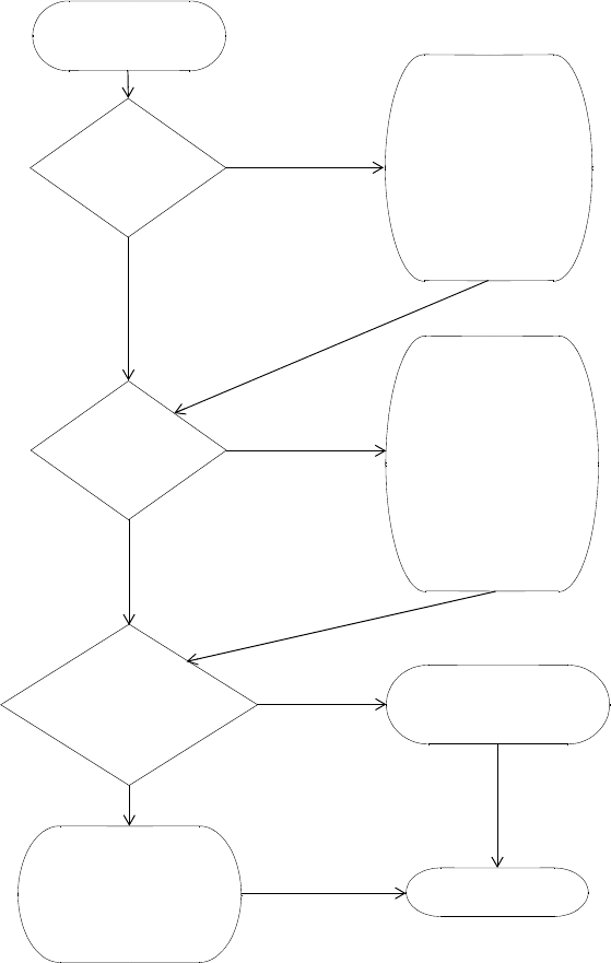
332 CHAPTER 16: CONFIGURING QUALITY OF SERVICE
Figure 24 QoS on WX Switches—Classification of Ingress Packets
WX receives packet.
Yes
No (802.1p = 0)
802.1p value
Set packet CoS
1 -> 1
2 -> 2
3 -> 3
4 -> 4
5 -> 5
6 -> 6
7 -> 7
based on 802.1p:
that is not 0?
DSCP value
that is not 0?
Look up CoS for
DSCP value and
8 - 15 -> 1
16 - 23 -> 2
24 - 31 -> 3
32 - 39 -> 4
40 - 47 -> 5
48 - 55 -> 6
56 - 63 -> 7
Yes
No (DCSP = 0)
set packet CoS:
ACE on egress VLAN
or MAP sets CoS? Yes
No
Set packet CoS
to ACE CoS value.
Use CoS mapped
from DSCP or
802.1p, or leave
CoS unset if 802.1p
and DSCP are both 0.
Mark egress packet.
0 - 7 -> 0
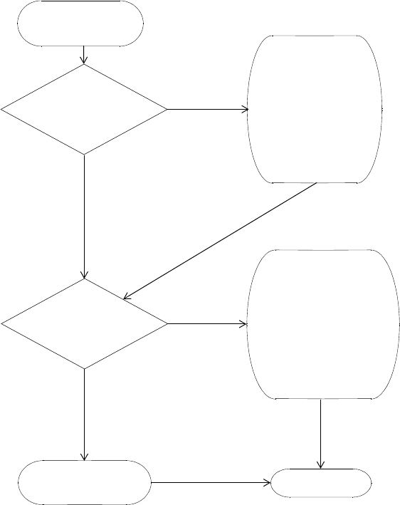
WMM QoS Mode 333
Figure 25 QoS on WX Switches—Marking of Egress Packets
WX has classified
Yes
No VLAN tag
Mark 802.1p
1 -> 1
2 -> 2
3 -> 3
4 -> 4
5 -> 5
6 -> 6
7 -> 7
with CoS value:
Yes
No
ingress packet.
Egress interface has
802.1Q VLAN tag?
Egress interface
is IP tunnel?
Transmit packet.
Do not mark DSCP.
Look up CoS and mark
packet’s DSCP value:
1 -> 8
2 -> 16
3 -> 24
4 -> 32
5 -> 40
6 -> 48
7 -> 56
334 CHAPTER 16: CONFIGURING QUALITY OF SERVICE
Figure 26 QoS on MAPs—Classification and Marking of Packets from Clients to
WX
MAP receives packet
from client.
Set packet CoS
1 -> 1
2 -> 2
3 -> 3
4 -> 4
5 -> 5
6 -> 6
7 -> 7
based on 802.11
Service Type:
Set tunnel’s IP ToS
to 802.1p value.
Look up CoS and mark
packet’s DSCP value:
1 -> 8
2 -> 16
3 -> 24
4 -> 32
5 -> 40
6 -> 48
7 -> 56
Transmit packet to WX.
Ye s
No
Static CoS
enabled?
Set packet CoS
with static CoS
value.
Set tunnel
DSCP value
Mark packet with
IP ToS to static
CoS value.
mapped to static
CoS value.
WMM QoS Mode 335
Figure 27 QoS on MAPs—Classification and Marking of Packets from WX to
Clients
The following sections describe in more detail how the WMM QoS mode
works on WX switches and MAPs.
MAP receives packet
from WX.
Map CoS value to MAP forwarding
0 or 3 -> Background
1 or 2 -> Best Effort
4 or 5 -> Video
6 or 7 -> Voice
Transmit packet to client.
Look up CoS for
DSCP value and
8 - 15 -> 1
16 - 23 -> 2
24 - 31 -> 3
32 - 39 -> 4
40 - 47 -> 5
48 - 55 -> 6
56 - 63 -> 7
set packet CoS:
Mark 802.11
Service Type
with CoS value.
queue:
0 - 7 -> 0
Ye s
No
Static CoS
enabled?
Set packet CoS
with static CoS
value.

336 CHAPTER 16: CONFIGURING QUALITY OF SERVICE
WMM QoS on the WX Switch
MSS performs classification on ingress to determine a packet’s CoS value.
This CoS value is used to mark the packet at the egress interface.
The classification and marking performed by the switch depend on
whether the ingress interface has an 802.1p or DSCP value other than 0,
and whether the egress interface is tagged or is an IP tunnel.
The mappings between DSCP and CoS values are configurable. (See
“Changing CoS Mappings” on page 344.) 802.1p and CoS values map
directly and are not configurable. DSCP 0 of the DSCP-to-CoS map is
reserved. 802.1p determines CoS for packets with DSCP 0. CoS 0 of the
CoS-to-DSCP map is also reserved. CoS 0 packets are marked with DSCP 0.
Table 27 shows how WMM priority information is mapped across the
network. When WMM is enabled, 3Com switches and MAPs perform
these mappings automatically.
You can use static CoS to assign the same CoS value to all packets for a
specific SSID. The static CoS value is assigned on the MAP, in both traffic
directions (from the client to the WX and from the WX to the client). (For
information, see “Configuring Static CoS” on page 343.)
Table 27 WMM Priority Mappings
Service
Type IP Precedence IP ToS DSCP 802.1p CoS
MAP
Forwarding
Queue
0 0 0 0 0 0 Background
3 3 0x60 24 3 3
1 1 0x20 8 1 1 Best Effort
2 2 0x40 16 2 2
4 4 0x80 32 4 4 Video
5 5 0xa0 40 5 5
6 6 0xc0 48 6 6 Voice
7 7 0xe0 56 7 7

WMM QoS Mode 337
You also can use ACLs to override marking for specific packets. Configure
ACEs that use the dscp option to match on ingress DSCP value, and use
the cos option to mark CoS. A CoS value assigned by an ACE overrides
the internal CoS value. (For information, see “Using ACLs to Change
CoS” on page 399.)
WMM QoS on a MAP MAPs use forwarding queues to prioritize traffic for wireless clients.
For a packet received by the MAP from a client, the MAP classifies the
packet based on the service type in the 802.11 header and maps the
service type value to an internal CoS value. The MAP then marks the
DSCP value in the IP tunnel header to the WX switch based on the
internal CoS value.
For a packet received from a WX switch and addressed to a client, the
MAP classifies the packet by mapping the DSCP value in the IP tunnel
header to an internal CoS value. The MAP then assigns the packet to a
forwarding queue based on the internal CoS value. The MAP also marks
the service type in the 802.11 header based on the internal CoS value.
A MAP uses the DSCP-to-CoS and CoS-to-DSCP mappings of the WX
switch that is managing it. If you change mappings on a WX switch, the
change also applies to the MAP. Likewise, if a MAP changes to another
WX switch (for example, after a MAP restart), the MAP uses the
mappings in effect on the new WX.
If the use-client-dscp option is enabled for a service profile, WMM QoS
is ignored, and the QoS level is classified based on the DSCP value.
802.11 data packets without WMM are classified as QoS level 0 unless
static CoS is enabled or the use-client-dscp option is enabled.
Table 28 lists the default mappings between a MAP’s internal CoS values
and its forwarding queues.
Table 28 Default CoS-to-MAP-Forwarding-Queue Mappings
CoS MAP Forwarding Queue
1 or 2 Background
0 or 3 Best Effort
4 or 5 Video
6 or 7 Voice
338 CHAPTER 16: CONFIGURING QUALITY OF SERVICE
(To display a MAP’s CoS mappings and queue usage statistics, see
“Displaying MAP Forwarding Queue Statistics” on page 349.)
Figure 28 shows an example of end-to-end QoS in a 3Com network. In
this example, voice traffic is prioritized based on WMM. This example
assumes that the QoS mappings are set to their default values.
Figure 28 WMM QoS in a 3Com Network
Figure 28 shows the following process:
1A user sends voice traffic from a WMM VoIP phone. The phone marks the
CoS field of the packet with service type 7, indicating that the packet is
for high priority (voice) traffic.
2MAP A receives the voice packet and classifies the packet by mapping the
service type in the 802.11 header to an internal CoS value. In this
example, the service type is 7 and maps to internal CoS 7.
Layer 3
WX Switch B
Srvc Type = 7 Voice Data . . .
IP ToS = 0xe0 Voice Data. . .
802.1p = 7 IP ToS = 0xe0 Voice Data. . .
802.1p = 7
Voice
Video
Best Effort
Bgrnd
WX Switch A
4
1
2
3
5
6
Voice Data. . .
Tnl Hdr IP ToS = 0xe0
Voice Data. . .
Tnl Hdr IP ToS = 0xe0
Layer 3
MAP A MAP B

WMM QoS Mode 339
The MAP encapsulates the data in an IP tunnel packet, and marks the
DSCP value in the tunnel header based on the internal CoS value. In this
example, the MAP maps internal CoS 7 to DSCP 56 and marks the IP
tunnel header’s DSCP field with value 56. The MAP then sends the packet
to the WX switch.
3WX A receives the packet on the IP tunnel connecting the WX to MAP A.
The WX classifies the packet based on the DSCP value in the IP header of
the tunnel packet (in this example, DSCP 56), and maps this value to an
internal CoS value (in this example, 7).
In this example, the WX interface with the MAP is untagged, so the WX
does not classify the packet based on its 802.1p value.
WX A marks the packet based on the packet’s internal CoS value. In this
example, the egress interface is in a VLAN and has an 802.1Q VLAN tag.
Therefore, the WX marks both the 802.1p value (with 7) and the tunnel
header’s DSCP value (with 56). WX A sends the packet to WX B on the IP
tunnel that connects the two switches.
In An ACL can override a packet’s marking. If a packet matches a permit
ACL mapped to the outbound traffic direction on the MAP port,
Distributed MAP, or user VLAN, and the ACL sets the CoS value, the
tunnel header’s DSCP value is marked based on the CoS value in the ACL
instead.
4WX B receives the packet from the Layer 3 cloud. The packet has an
802.1Q VLAN tag, so the WX classifies the packet by mapping its 802.1p
value (in this example, 7) to the matching internal CoS value (also 7).
However, because the packet also has a non-zero value in the DSCP field
of the tunnel header, the WX reclassifies the packet by mapping the
DSCP value (56) to an internal CoS value (7) instead.
5WX B encapsulates the packet in an IP tunnel packet and marks the DSCP
value in the tunnel header based on the packet’s internal CoS value. In
this example, the WX marks the tunnel header with DSCP 56. WX B
sends the packet to MAP B on the IP tunnel that connects them.
6MAP B receives the packet and does the following:
Maps the DSCP value in the tunnel header (56) to an internal CoS value (7).
Marks the packet’s service type based on the internal CoS value (7).
Places the packet in a forwarding queue (Voice) based on the internal
CoS value (7).

340 CHAPTER 16: CONFIGURING QUALITY OF SERVICE
In this example, the MAP places the packet in the Voice forwarding
queue. The Voice queue has statistically more access to the air than
the other queues, so the user’s voice traffic receives priority treatment.
SVP QoS Mode
The SVP QoS mode optimizes forwarding of SVP traffic by setting the
random wait time a MAP radio waits before transmitting the traffic to 0
microseconds.
Normally, a MAP radio waits an additional number of microseconds
following the fixed wait time, before forwarding a queued packet or
frame. Each forwarding queue has a different range of possible random
wait times. The Voice queue has the narrowest range, whereas the
Background and Best Effort queues have the widest range. The random
wait times ensure that the Voice queue gets statistically more access to
the air than the other queues.
By setting the random wait time to 0 for SVP, the SVP QoS mode provides SVP
traffic the greatest possible access to the air, on a statistical basis. The QoS
mode affects forwarding of SVP traffic only. The random wait times for other
types of traffic are the same as those used when the QoS mode is WMM.
Call Admission
Control
Call Admission Control (CAC) is an optional feature that helps ensure that
high-priority clients have adequate bandwidth, by limiting the number of
active sessions MAP radios can have for an SSID. For example, you can
limit the number of active sessions on a VoIP SSID to ensure that each call
receives the bandwidth required for quality voice service.
You can use CAC with either QoS mode (WMM or SVP).
CAC is disabled by default. You can enable session-based CAC on a
service-profile basis. When enabled, CAC limits the number of active
sessions a radio can have to 14 by default. You can change the maximum
number of sessions to a value from 0 to 100.
CAC is configured on a service profile basis and limits association to
radios only for the service profile’s SSID. Association to the radios by
clients on other SSIDs is not limited. To ensure voice quality, do not map
other service profiles to the radio profile you plan to use for voice traffic.
(To configure CAC, see “Configuring Call Admission Control” on
page 343.)

WMM QoS Mode 341
Broadcast Control You also can enhance bandwidth availability on an SSID by enabling the
following broadcast control features:
Proxy ARP—WX responds on behalf of wireless clients to ARP requests
for their IP addresses.
DHCP Restrict—WX captures and does not forward any traffic except
DHCP traffic for a wireless client who is still being authenticated and
authorized.
No Broadcast—Sends unicasts to clients for ARP requests and DHCP
Offers and Acks instead of forwarding them as multicasts.
All these broadcast control options are disabled by default.
(To enable broadcast control features, see “Enabling Broadcast Control”
on page 345.)
Static CoS You can configure MSS to mark all wireless traffic on an SSID with a
specific CoS value. When static CoS is enabled, the MAP marks all traffic
between clients and the WX for a given SSID with the static CoS value.
The static CoS value must be configured on the SSID’s service profile.
Static CoS is the simplest method of CoS marking to configure. However,
the static CoS value applies to all traffic regardless of traffic type. To
instead assign CoS based on specific traffic types within an SSID, use an
ACL. (See “Overriding CoS”.)
When static CoS is enabled, you cannot override the static CoS value by
using ACLs to mark CoS.
Overriding CoS You can configure an ACL that marks packets that match the ACL with a
specific CoS value. CoS is not changed in packets that do not match the
ACE (ACL rule) that sets the CoS. (For more information, see “Enabling
Prioritization for Legacy Voice over IP” on page 401.)
If static CoS is enabled, the static CoS value is always used. The CoS
cannot be changed using an ACL.

342 CHAPTER 16: CONFIGURING QUALITY OF SERVICE
Changing QoS
Settings
You can change the settings of the following QoS options:
QoS mode
U-APSD support
CAC state and maximum number of sessions
Broadcast control
Static CoS state and CoS value
DSCP-CoS mappings
Using client DSCP value to classify QoS level of IP packets
The QoS mode is configurable on a radio-profile basis. CAC and static
CoS are configurable on a service-profile basis. DSCP-CoS mapping is
configurable on a global switch basis.
Changing the QoS
Mode
The default QoS mode is WMM. To change the QoS mode on a radio
profile, use the following command:
set radio-profile name qos-mode {svp | wmm}
For example, the following command changes the QoS mode for radio
profile rp1 to SVP:
WX1200# set radio-profile rp1 qos-mode svp
success: change accepted.
SVP configuration requires ACLs to set CoS, in addition to the SVP QoS
mode. (For information, see “Enabling SVP Optimization for SpectraLink
Phones” on page 404.)
Enabling U-APSD
Support
U-APSD support is disabled by default. To enable it on a radio profile, use
the following command:
set radio-profile name wmm-powersave {enable | disable}
For example, the following command enables U-APSD on radio profile
rp1:
WX# set radio-profile rp1 wmm-powersave enable
success: change accepted.
Changing QoS Settings 343
Configuring Call
Admission Control
To configure CAC for an SSID, enable the feature on the SSID’s service
profile. When enabled, CAC limits the number of active sessions a radio
can have to 14 by default. You can change the maximum number of
sessions to a value from 0 to 100.
Enabling CAC
To enable or disable CAC on a service profile, use the following command:
set service-profile name cac-mode {none |session}
For example, to enable session-based CAC on service profile sp1, use the
following command:
WX1200# set service-profile sp1 cac-mode session
success: change accepted.
Changing the Maximum Number of Active Sessions
When CAC is enabled, the maximum number of active sessions a radio
can have is 14 by default. To change the maximum number of sessions,
use the following command:
set service-profile name cac-session max-sessions
The max-sessions can be a value from 0 to 100.
For example, to change the maximum number of sessions for radios used
by service profile sp1 to 10, use the following command:
WX1200# set service-profile sp1 cac-session 10
success: change accepted.
Configuring Static
CoS
To configure static CoS for an SSID, enable the feature and set the CoS
value. MAP radios that forward traffic for the SSID mark all the traffic
with the static CoS value and use the corresponding forwarding queue to
forward the traffic. The static CoS value applies to all traffic on the SSID.
To enable static CoS and set the CoS value, use the following commands:
set service-profile name static-cos {enable |disable}
set service-profile name cos level
The level can be a value from 0 (lowest priority) to 7 (highest priority). The
default is 0.

344 CHAPTER 16: CONFIGURING QUALITY OF SERVICE
For example, to configure static CoS 7 for service profile sp1, use the
following commands:
WX1200# set service-profile sp1 static-cos enable
success: change accepted.
WX1200# set service-profile sp1 cos 7
success: change accepted.
Changing CoS
Mappings
To change CoS mappings, use the following commands:
set qos dscp-to-cos-map dscp-range cos level
set qos cos-to-dscp-map level dscp dscp-value
The first command changes the mapping of ingress DSCP values to the
internal QoS table when marking packets. The second command changes
the mappings of the internal QoS values to DSCP value when tagging
outbound packets.
The following command changes the mapping of DSCP value 45 from
CoS value 5 to CoS value 7. (The change affects classification but does
not affect marking.)
WX1200# set qos dscp-to-cos-map 45 cos 7
success: change accepted.
The following command changes the mapping of CoS value 6 from DSCP
value 48 to DSCP value 55. (The change affects marking but does not
affect classification.)
WX4400# set qos cos-to-dscp-map 6 dscp 55
success: change accepted.
Using the Client’s
DSCP Value to
Classify QoS Level
To configure MSS to classify the QoS level of IP packets based on their
DSCP value, instead of their 802.11 priority, use the following command:
set service-profile name use-client-dscp {enable | disable}
If this command is enabled in the service profile, the 802.11 QoS level is
ignored, and MSS classifies QoS level of IP packets based on their DSCP value.
The following command enables mapping the QoS level of IP packets
based on their DSCP value for service profile sp1:
WX# set service-profile sp1 use-client-dscp enable
success: change accepted.

Displaying QoS Information 345
Enabling Broadcast
Control
To enable broadcast control features on a service-profile basis, using the
following commands:
set service-profile name proxy-arp {enable | disable}
set service-profile name dhcp-restrict {enable | disable}
set service-profile name no-broadcast {enable | disable}
For example, to enable all these broadcast control features in service
profile sp1, use the following commands:
WX1200# set service-profile sp1 proxy-arp enable
success: change accepted.
WX1200# set service-profile sp1 dhcp-restrict enable
success: change accepted.
WX1200# set service-profile sp1 no-broadcast enable
success: change accepted.
Displaying QoS
Information
You can display the following types of information for QoS:
Radio profile QoS settings: QoS mode
Service profile QoS settings: CAC, static CoS, and broadcast control
settings
Broadcast control settings
Default CoS mappings
Individual DSCP-to-CoS or CoS-to-DSCP mappings
The DSCP table (a reference of standard mappings from DSCP to IP
ToS and IP precedence)
QoS Statistics for the MAP forwarding queues
Displaying a Radio
Profile’s QoS Settings
To display the QoS mode and all other settings for a radio profile, use the
following command:
display radio-profile {name | ?}
The following example shows the configuration of radio profile rp1.
WX1200# display radio-profile rp1
Beacon Interval: 100 DTIM Interval: 1
Max Tx Lifetime: 2000 Max Rx Lifetime: 2000
RTS Threshold: 2346 Frag Threshold: 2346
Long Preamble: no Tune Channel: yes
Tune Power: no Tune Channel Interval: 3600
346 CHAPTER 16: CONFIGURING QUALITY OF SERVICE
Tune Power Interval: 600 Channel Holddown: 300
Power Backoff Timer: 10 Countermeasures: none
Active-Scan: yes QoS Mode: wmm
Service profiles: sp1
In this example, the QoS mode is WMM.
(For more information about this command’s output, see the “MAP
Commands” chapter in the Wireless LAN Switch and Controller
Configuration Guide.)
Displaying a Service
Profile’s QoS Settings
To display QoS settings and all other settings for a service profile, use the
following command:
display service-profile {name | ?}
The following example shows the configuration of the sp1 service profile.
WX1200# display service-profile sp1
ssid-name: corp2 ssid-type: crypto
Beacon: yes Proxy ARP: no
DHCP restrict: no No broadcast: no
Short retry limit: 5 Long retry limit: 5
Auth fallthru: none Sygate On-Demand (SODA): no
Enforce SODA checks: yes SODA remediation ACL:
Custom success web-page: Custom failure web-page:
Custom logout web-page: Custom agent-directory:
Static COS: no COS: 0
CAC mode: session CAC sessions: 14
User idle timeout: 180 Idle client probing: yes
Web Portal Session Timeout: 5
WEP Key 1 value: <none> WEP Key 2 value: <none>
WEP Key 3 value: <none> WEP Key 4 value: <none>
WEP Unicast Index: 1 WEP Multicast Index: 1
Shared Key Auth: NO
WPA enabled:
ciphers: cipher-tkip
authentication: 802.1X
TKIP countermeasures time: 60000ms
11a beacon rate: 6.0 multicast rate: AUTO
11a mandatory rate: 6.0,12.0,24.0 standard rates: 9.0,18.0,36.0,48.0,54.0
11b beacon rate: 2.0 multicast rate: AUTO
11b mandatory rate: 1.0,2.0 standard rates: 5.5,11.0
11g beacon rate: 2.0 multicast rate: AUTO
11g mandatory rate: 1.0,2.0,5.5,11.0 standard rates: 6.0,9.0,12.0,18.0,24.0,
36.0,48.0,54.0

Displaying QoS Information 347
Configuration information for some settings appears in other chapters. To
configure transmit rates, or the long or short retry, see “Configuring a
Service Profile” on page 233. To configure the user-idle timeout and
idle-client probing, see “Displaying and Changing Network Session
Timers” on page 565.
(For more information about this command’s output, see the “MAP
Commands” chapter in the Wireless LAN Switch and Controller
Configuration Guide.)
Displaying CAC Session Information
To display current CAC session counts on all MAPs using a specified
service profile, when session-based CAC is enabled, use the following
command:
display service-profile name cac session
The following example displays information about CAC session counts for
service profile sp1:
WX# display service-profile sp1 cac session
Service Profile sp1
CAC Mode SESSION
Max Sessions 14
(For more information about this command’s output, see the “MAP
Commands” chapter in the Wireless LAN Switch and Controller
Configuration Guide)
Displaying CoS
Mappings
MSS provides commands for displaying the default CoS mappings and
configured mappings.
Displaying the Default CoS Mappings
To display the default CoS mappings, use the following command:
WX1200# display qos default
Ingress QoS Classification Map (dscp-to-cos)
Ingress DSCP CoS Level
===============================================================================
00-09 0 0 0 0 0 0 0 0 1 1
10-19 1 1 1 1 1 1 2 2 2 2
20-29 2 2 2 2 3 3 3 3 3 3
30-39 3 3 4 4 4 4 4 4 4 4
348 CHAPTER 16: CONFIGURING QUALITY OF SERVICE
40-49 5 5 5 5 5 5 5 5 6 6
50-59 6 6 6 6 6 6 7 7 7 7
60-63 7 7 7 7
Egress QoS Marking Map (cos-to-dscp)
CoS Level 0 1 2 3 4 5 6 7
===============================================================================
Egress DSCP 0 8 16 24 32 40 48 56
Egress ToS byte 0x00 0x20 0x40 0x60 0x80 0xA0 0xC0 0xE0
Displaying a DSCP-to-CoS Mapping
To display the CoS value to which a specific DSCP value is mapped during
classification, use the following command:
display qos dscp-to-cos-map dscp-value
The following command displays the CoS value to which DSCP value 55 is
mapped:
WX1200# display qos dscp-to-cos-map 55
dscp 55 is classified as cos 6
Displaying a CoS-to-DSCP Mapping
To display the DSCP value to which a specific CoS value is mapped during
marking, use the following command:
display qos cos-to-dscp-map cos-value
The following command displays the DSCP value to which CoS value 6 is
mapped:
WX1200# display qos cos-to-dscp-map 6
cos 6 is marked with dscp 48 (tos 0xC0)
Displaying QoS Information 349
Displaying the DSCP
Table
To display the standard mappings of DSCP, ToS, and precedence values,
use the following command:
WX1200# display qos dscp-table
DSCP TOS precedence tos
dec hex dec hex
-----------------------------------------------
0 0x00 0 0x00 0 0
1 0x01 4 0x04 0 2
2 0x02 8 0x08 0 4
3 0x03 12 0x0c 0 6
4 0x04 16 0x10 0 8
5 0x05 20 0x14 0 10
6 0x06 24 0x18 0 12
7 0x07 28 0x1c 0 14
8 0x08 32 0x20 1 0
9 0x09 36 0x24 1 2
...
63 0x3f 252 0xfc 7 14
Displaying MAP
Forwarding Queue
Statistics
You can display statistics for MAP forwarding queues, using the following
commands:
display ap qos-stats [apnumber] [clear]
The clear option clears the counters after displaying their values.
The following command shows statistics for the MAP forwarding queues
on a Distributed MAP:
WX# display ap qos-stats 4
350 CHAPTER 16: CONFIGURING QUALITY OF SERVICE
17 CONFIGURING AND MANAGING
SPANNING TREE PROTOCOL
The purpose of the Spanning Tree Protocol (STP) is to maintain a loop-free
network. A loop-free path is accomplished when a device recognizes a
loop in the topology and blocks one or more redundant paths.
Overview Mobility System Software (MSS) supports 802.1D and Per-VLAN Spanning
Tree protocol (PVST+).
MSS uses 802.1D bridge protocol data units (BPDUs) on VLAN ports
that are untagged. However, each VLAN still runs its own instance of
STP, even if two or more VLANs contain untagged ports. To run a
single instance of STP in 802.1D mode on the entire switch, configure
all network ports as untagged members of the same VLAN.
MSS uses PVST+ BPDUs on VLAN ports that are tagged. PVST+ BPDUs
include tag information in the 802.1Q field of the BPDUs. MSS runs a
separate instance of PVST+ on each tagged VLAN.
STP does not run on MAP access ports or wired authentication ports and
does not affect traffic flow on these port types.
When you create a VLAN, STP is disabled on the new VLAN by default,
regardless of the STP state of other VLANs on the device.
The IEEE 802.1D spanning tree specifications refer to networking devices
that forward Layer 2 traffic as bridges. In this context, a WX switch is a
bridge. Where this manual or the product interface uses the term bridge,
you can assume the term is applicable to the WX switch.

352 CHAPTER 17: CONFIGURING AND MANAGING SPANNING TREE PROTOCOL
Enabling the
Spanning Tree
Protocol
STP is disabled by default. You can enable STP globally or on individual
VLANs.
To enable STP, use the following command:
set spantree {enable | disable}
[{all | vlan vlan-id | port port-list vlan-id}]
To enable STP on all VLANs configured on a WX switch, type the
following command:
WX1200# set spantree enable
success: change accepted.
To verify the STP state and display the STP parameter settings, enter the
display spantree command. For information, see “Displaying Spanning
Tree Information” on page 361.
Changing Standard
Spanning Tree
Parameters
You can change the following standard STP parameters:
Bridge priority
Port cost
Port priority
Bridge Priority The bridge priority determines the WX switch’s eligibility to become the
root bridge. You can set this parameter globally or on individual VLANs.
The root bridge is elected based on the bridge priority of each device in
the spanning tree. The device with the highest bridge priority is elected to
be the root bridge for the spanning tree. The bridge priority is a numeric
value from 0 through 65,535. Lower numeric values represent higher
priorities. The highest priority is 0, and the lowest priority is 65,535. The
default bridge priority for all devices is 32,768.
If more than one device has the highest bridge priority (lowest numeric
value), the device with the lowest MAC address becomes the root bridge.
If the root bridge fails, STP elects a new root bridge based on the bridge
priorities of the remaining bridges.

Changing Standard Spanning Tree Parameters 353
Port Cost Port cost is a numeric value that STP adds to the total cost of a path to
the root bridge. When a designated bridge has multiple equal-cost paths
to the root bridge, the designated bridge uses the path with the lowest
total cost. You can set this parameter on an individual port basis, for all
VLANs the port is in, or for specific VLANs.
You can specify a value from 1 through 65,535 for the port cost. The
default depends on the port speed and link type. Table 29 lists the
defaults for STP port path cost.
Port Priority Port priority is the eligibility of the port to be the designated port to the
root bridge, and thus part of the path to the root bridge. When the WX
switch has more than one link to the root bridge, STP uses the link with
the lowest priority value. You can set this parameter on an individual port
basis, for all VLANs the port is in, or for specific VLANs.
Specify a priority from 0 (highest priority) through 255 (lowest priority).
The default is 128.
Changing the Bridge
Priority
To change the bridge priority, use the following command:
set spantree priority value {all | vlan vlan-id}
Specify a bridge priority from 0 through 65,535. The default is 32,768.
The all option applies the change globally to all VLANs. Alternatively,
specify an individual VLAN.
Table 29 SNMP Port Path Cost Defaults
Port Speed Link Type Default Port Path Cost
1000 Mbps Full Duplex Aggregate
Link (Port Group) 19
1000 Mbps Full Duplex 4
100 Mbps Full Duplex Aggregate
Link (Port Group) 19
100 Mbps Full Duplex 18
100 Mbps Half Duplex 19
10 Mbps Full Duplex Aggregate
Link (Port Group) 19
10 Mbps Full Duplex 95
10 Mbps Half Duplex 100
354 CHAPTER 17: CONFIGURING AND MANAGING SPANNING TREE PROTOCOL
To change the bridge priority of VLAN pink to 69, type the following
command:
WX1200# set spantree priority 69 vlan pink
success: change accepted.
Changing STP Port
Parameters
You can change the STP cost and priority of an individual port, on a
global basis or an individual VLAN basis.
Changing the STP Port Cost
To change the cost of a port, use one of the following commands.
set spantree portcost port-list cost cost
set spantree portvlancost port-list cost cost {all | vlan
vlan-id}
The set spantree portcost command changes the cost for ports in the
default VLAN (VLAN 1) only. The set spantree portvlancost command
changes the cost for ports in a specific other VLAN or in all VLANs.
Specify a value from 1 through 65,535 for the cost. The default depends
on the port speed and link type. (See Table 29 on page 353.)
The all option applies the change to all VLANs. Alternatively, specify an
individual VLAN.
To change the cost on ports 3 and 4 in the default VLAN to 20, type the
following command:
WX1200# set spantree portcost 3,4 cost 20
success: change accepted.
To change the cost for the same ports in VLAN mauve, type the following
command:
WX1200# set spantree portvlancost 3,4 cost 20 vlan mauve
success: change accepted.
Resetting the STP Port Cost to the Default Value
To reset the STP port cost to the default value, use one of the following
commands:
clear spantree portcost port-list
clear spantree portvlancost port-list {all | vlan vlan-id}
Changing Standard Spanning Tree Parameters 355
The command applies only to the ports you specify. The port cost on
other ports remains unchanged.
To reset the cost of ports 3 and 4 in the default VLAN to the default
value, type the following command:
WX1200# clear spantree portcost 3-4
success: change accepted.
To reset the cost of ports 3 and 4 for VLAN beige, type the following
command:
WX1200# clear spantree portvlancost 3-4 vlan beige
success: change accepted.
Changing the STP Port Priority
To change the priority of a port, use one of the following commands:
set spantree portpri port-list priority value
set spantree portvlanpri port-list priority value {all |
vlan vlan-id}
The set spantree portpri command changes the priority for ports in the
default VLAN (VLAN 1) only. The set spantree portvlanpri command
changes the priority for ports in a specific other VLAN or in all VLANs.
Specify a priority from 0 (highest priority) through 255 (lowest priority).
The default is 128.
The all option applies the change to all VLANs. Alternatively, specify an
individual VLAN.
To set the priority of ports 3 and 4 in the default VLAN to 48, type the
following command:
WX1200# set spantree portpri 3-4 priority 48
success: change accepted.
To set the priority of ports 3 and 4 to 48 in VLAN mauve, type the
following command:
WX1200# set spantree portvlanpri 3-4 priority 48 vlan mauve
success: change accepted.
356 CHAPTER 17: CONFIGURING AND MANAGING SPANNING TREE PROTOCOL
Resetting the STP Port Priority to the Default Value
To reset the STP port priority to the default value, use one of the
following commands:
clear spantree portpri port-list
clear spantree portvlanpri port-list {all | vlan vlan-id}
The command applies only to the ports you specify. The port cost on
other ports remains unchanged.
Changing the STP Port Priority
To change the priority of a port, use one of the following commands:
set spantree portpri port-list priority value
set spantree portvlanpri port-list priority value {all |
vlan vlan-id}
The set spantree portpri command changes the priority for ports in the
default VLAN (VLAN 1) only. The set spantree portvlanpri command
changes the priority for ports in a specific other VLAN or in all VLANs.
Specify a priority from 0 (highest priority) through 255 (lowest priority).
The default is 128.
The all option applies the change to all VLANs. Alternatively, specify an
individual VLAN.
To set the priority of ports 3 and 4 in the default VLAN to 48, type the
following command:
WX1200# set spantree portpri 3-4 priority 48
success: change accepted.
To set the priority of ports 3 and 4 to 48 in VLAN mauve, type the
following command:
WX1200# set spantree portvlanpri 3-4 priority 48 vlan mauve
success: change accepted.
Resetting the STP Port Priority to the Default Value
To reset the STP port priority to the default value, use one of the
following commands:
clear spantree portpri port-list
clear spantree portvlanpri port-list {all | vlan vlan-id}
Changing Standard Spanning Tree Parameters 357
The command applies only to the ports you specify. The port cost on
other ports remains unchanged.
Changing Spanning
Tree Timers
You can change the following STP timers:
Hello interval — The interval between configuration messages sent
by a WX switch when the switch is acting as the root bridge. You can
specify an interval from 1 through 10 seconds. The default is 2
seconds.
Forwarding delay — The period of time a bridge other than the root
bridge waits after receiving a topology change notification to begin
forwarding data packets. You can specify a delay from 4 through 30
seconds. The default is 15 seconds. (The root bridge always forwards
traffic.)
Maximum age — The period of time that a WX switch acting as a
designated bridge waits for a new hello packet from the root bridge
before determining that the root bridge is no longer available and
initiating a topology change. You can specify an age from 6 through
40 seconds. The default is 20 seconds.
Changing the STP Hello Interval
To change the hello interval, use the following command:
set spantree hello interval {all | vlan vlan-id}
Specify an interval from 1 through 10 seconds. The default is 2 seconds.
The all option applies the change to all VLANs. Alternatively, specify an
individual VLAN.
To change the hello interval for all VLANs to 4 seconds, type the following
command:
WX1200# set spantree hello 4 all
success: change accepted.
Changing the STP Forwarding Delay
To change the forwarding delay, use the following command:
set spantree fwddelay delay {all | vlan vlan-id}
Specify a delay from 4 through 30 seconds. The default is 15 seconds.

358 CHAPTER 17: CONFIGURING AND MANAGING SPANNING TREE PROTOCOL
The all option applies the change to all VLANs. Alternatively, specify an
individual VLAN.
To change the forwarding delay on VLAN pink to 20 seconds, type the
following command:
WX1200# set spantree fwddelay 20 vlan pink
success: change accepted.
Changing the STP Maximum Age
To change the maximum age, use the following command:
set spantree maxage aging-time {all | vlan vlan-id}
Specify an age from 6 through 40 seconds. The default is 20 seconds.
The all option applies the change to all VLANs. Alternatively, specify an
individual VLAN.
To change the maximum acceptable age for root bridge hello packets on
all VLANs to 15 seconds, type the following command:
WX1200# set spantree maxage 15 all
success: change accepted.
Configuring and
Managing STP Fast
Convergence
Features
The standard STP timers delay traffic forwarding briefly after a topology
change. The time a port takes to change from the listening state to the
learning state or from the learning state to the forwarding state is called
the forwarding delay. In some configurations, this delay is unnecessary.
The WX switch provides the following fast convergence features to
bypass the forwarding delay:
Port fast
Backbone fast
Uplink fast
Port Fast
Convergence
Port fast convergence bypasses both the listening and learning stages and
immediately places a port in the forwarding state. You can use port fast
convergence on ports that are directly connected to servers, hosts, or
other MAC stations.
Do not use port fast convergence on ports connected to other bridges.

Configuring and Managing STP Fast Convergence Features 359
Backbone Fast
Convergence
Backbone fast convergence accelerates a port’s recovery following the
failure of an indirect link. Normally, when a forwarding link fails, a bridge
that is not directly connected to the link does not detect the link change
until the maximum age timer expires. Backbone fast convergence enables
the WX switch to listen for bridge protocol data units (BPDUs) sent by a
designated bridge when the designated bridge’s link to the root bridge
fails. The switch immediately verifies whether BPDU information stored
on a port is still valid. If not, the bridge immediately starts the listening
stage on the port.
CAUTION: The backbone fast convergence feature is not compatible
with switches that are running standard IEEE 802.1D Spanning Tree
implementations. This includes switches running Rapid Spanning Tree or
Multiple Spanning Tree.
If you plan to use the backbone fast convergence feature, you must
enable it on all the bridges in the spanning tree.
Uplink Fast
Convergence
Uplink fast convergence enables a WX switch that has redundant links to
the network core to immediately change the state of a backup link to
forwarding if the primary link to the root fails. Uplink fast convergence
bypasses the listening and learning states to immediately enter the
forwarding state.
The uplink fast convergence feature is applicable to bridges that are
acting as access switches to the network core (distribution layer) but are
not in the core themselves. Do not enable the feature on WX switches
that are in the network core.
Configuring Port Fast
Convergence
To enable or disable port fast convergence, use the following command:
set spantree portfast port port-list {enable | disable}
To enable port fast convergence on ports 1, 3, and 5, type the following
command:
WX1200# set spantree portfast port 1,3,5 enable
success: change accepted.
360 CHAPTER 17: CONFIGURING AND MANAGING SPANNING TREE PROTOCOL
Displaying Port Fast
Convergence
Information
To display port fast convergence information, use the following command:
display spantree portfast [port-list]
To display port fast convergence information for all ports, type the
following command:
WX1200# display spantree portfast
Port Vlan Portfast
------------------------- ---- ----------
1 1 disable
2 1 disable
3 1 disable
4 1 enable
7 1 disable
8 1 disable
5 2 enable
6 2 enable
In this example, port fast convergence is enabled on ports 5 and 6 in
VLAN 2 and port 4 in VLAN 1.
Configuring
Backbone Fast
Convergence
To enable or disable backbone fast convergence, use the following
command:
set spantree backbonefast {enable | disable}
To enable backbone fast convergence on all VLANs, type the following
command:
WX1200# set spantree backbonefast enable
success: change accepted.
Displaying the
Backbone Fast
Convergence State
To display the state of the backbone fast convergence feature, use the
following command:
display spantree backbonefast
Here is an example:
WX1200# display spantree backbonefast
Backbonefast is enabled
In this example, backbone fast convergence is enabled.

Displaying Spanning Tree Information 361
Configuring Uplink
Fast Convergence
To enable or disable uplink fast convergence, use the following
command:
set spantree uplinkfast {enable | disable}
Displaying Uplink
Fast Convergence
Information
To display uplink fast convergence information, use the following
command:
display spantree uplinkfast [vlan vlan-id]
The following command displays uplink fast convergence information for
all VLANs:
WX1200# display spantree uplinkfast
VLAN port list
------------------------------------------------------------
1 1(fwd),2,3
In this example, ports 1, 2, and 3 provide redundant links to the network
core. Port 1 is forwarding traffic. The remaining ports block traffic to
prevent a loop.
Displaying
Spanning Tree
Information
You can use CLI commands to display the following STP information:
Bridge STP settings and individual port information
Blocked ports
Statistics
Port fast, backbone fast, and uplink fast convergence information
For information about the display commands for the fast convergence
features, see “Configuring and Managing STP Fast Convergence
Features” on page 358.
Displaying STP Bridge
and Port Information
To display STP bridge and port information, use the following command:
display spantree [port port-list | vlan vlan-id] [active]
By default, STP information for all ports and all VLANs is displayed. To
display STP information for specific ports or a specific VLAN only, enter a
port list or a VLAN name or number. For each VLAN, only the ports
contained in the VLAN are listed in the command output.
362 CHAPTER 17: CONFIGURING AND MANAGING SPANNING TREE PROTOCOL
To list only the ports that are in the active (forwarding) state, enter the
active option.
To display STP information for VLAN mauve, type the following command:
WX1200# display spantree vlan mauve
VLAN 3
Spanning tree mode PVST+
Spanning tree type IEEE
Spanning tree enabled
Designated Root 00-02-4a-70-49-f7
Designated Root Priority 32768
Designated Root Path Cost 19
Designated Root Port 1
Root Max Age 20 sec Hello Time 2 sec Forward Delay 15 sec
Bridge ID MAC ADDR 00-0b-0e-02-76-f7
Bridge ID Priority 32768
Bridge Max Age 20 sec Hello Time 2 sec Forward Delay 15 sec
Port Vlan STP-State Cost Prio Portfast
------------------------------------------------------------------------------
1 1 Forwarding 19 128 Disabled
2 1 Blocking 19 128 Disabled
3 1 Blocking 19 128 Disabled
5 1 Forwarding 19 128 Disabled
6 1 Blocking 19 128 Disabled
In this example, VLAN mauve contains ports 1 through 3, 5 and 6. Ports 1
and 5 are forwarding traffic. The other ports are blocking traffic.
(For more information about the fields in the output, see the Wireless
LAN Switch and Controller Command Reference.)
Displaying the STP
Port Cost on a VLAN
Basis
To display a brief list of the STP port cost for a port in each of its VLANs,
use the following command:
display spantree portvlancost port-list
This command displays the same information as the display spantree
command’s Cost field in a concise format for all VLANs. The display
spantree command lists all the STP information separately for each VLAN.
To display the STP port cost of port 1, type the following command:
WX1200# display spantree portvlancost 1
port 1 VLAN 1 have path cost 19
Displaying Spanning Tree Information 363
Displaying Blocked
STP Ports
To display information about ports that are in the STP blocking state, use
the following command:
display spantree blockedports [vlan vlan-id]
To display information about blocked ports on a WX switch for the
default VLAN (VLAN 1), type the following command:
WX1200# display spantree blockedports vlan default
Port Vlan STP-State Cost Prio Portfast
------------------------------------------------------------------------
2 190 Blocking 4 128 Disabled
Number of blocked ports (segments) in VLAN 1 : 1
(For information about the fields in the output, see the Wireless LAN
Switch and Controller Command Reference.)
Displaying Spanning
Tree Statistics
To display STP statistics, use the following command:
display spantree statistics [port-list [vlan vlan-id]]
To display STP statistics for port 1, type the following command:
WX1200# display spantree statistics 1
BPDU related parameters
Port 1 VLAN 1
spanning tree enabled for VLAN = 1
port spanning tree enabled
state Forwarding
port_id 0x8015
port_number 0x15
path cost 0x4
message age (port/VLAN) 0(20)
designated_root 00-0b-0e-00-04-30
designated cost 0x0
designated_bridge 00-0b-0e-00-04-30
designated_port 38
top_change_ack FALSE
config_pending FALSE
port_inconsistency none
364 CHAPTER 17: CONFIGURING AND MANAGING SPANNING TREE PROTOCOL
Port based information statistics
config BPDU's xmitted(port/VLAN) 0 (1)
config BPDU's received(port/VLAN) 21825 (43649)
tcn BPDU's xmitted(port/VLAN) 0 (0)
tcn BPDU's received(port/VLAN) 2 (2)
forward transition count (port/VLAN) 1 (1)
scp failure count 0
root inc trans count (port/VLAN) 1 (1)
inhibit loopguard FALSE
loop inc trans count 0 (0)
Status of Port Timers
forward delay timer INACTIVE
forward delay timer value 15
message age timer ACTIVE
message age timer value 0
topology change timer INACTIVE
topology change timer value 0
hold timer INACTIVE
hold timer value 0
delay root port timer INACTIVE
delay root port timer value 0
delay root port timer restarted is FALSE
VLAN based information & statistics
spanning tree type ieee
spanning tree multicast address 01-00-0c-cc-cc-cd
bridge priority 32768
bridge MAC address 00-0b-0e-12-34-56
bridge hello time 2
bridge forward delay 15
topology change initiator: 0
last topology change occurred: Tue Jul 01 2003
22:33:36.
topology change FALSE
topology change time 35
topology change detected FALSE
topology change count 1
topology change last recvd. from 00-0b-0e-02-76-f6

Spanning Tree Configuration Scenario 365
Other port specific info
dynamic max age transition 0
port BPDU ok count 21825
msg age expiry count 0
link loading 0
BPDU in processing FALSE
num of similar BPDU's to process 0
received_inferior_bpdu FALSE
next state 0
src MAC count 21807
total src MAC count 21825
curr_src_mac 00-0b-0e-00-04-30
next_src_mac 00-0b-0e-02-76-f6
(For information about the fields in the output, see the Wireless LAN
Switch and Controller Command Reference.)
Clearing STP Statistics To clear the STP statistics counters, use the following command.
clear spantree statistics port-list [vlan vlan-id]
As soon as you enter the command, MSS resets the STP counters for the
specified ports or VLANs to 0. The software then begins incrementing the
counters again.
Spanning Tree
Configuration
Scenario
This scenario configures a VLAN named backbone for a WX switch's
connections to the network backbone, adds ports 1 and 2 to the VLAN,
and enables STP on the VLAN to prevent loops.
1Remove the network cables from ports 21 and 22 or use MSS to disable
the ports. This prevents a loop until you complete the STP configuration.
To disable the ports and verify the results, type the following commands:
WX1200# set port disable 1-2
success: set "disable" on port 1-2
WX1200# display port status
Port Name Admin Oper Config Actual Type Media
==========================================================
1 down down auto network
2 down down auto network
3 up down auto network 10/100BaseTx
4 up down auto network 10/100BaseTx
5 up down auto network 10/100BaseTx
6 up down auto network 10/100BaseTx
366 CHAPTER 17: CONFIGURING AND MANAGING SPANNING TREE PROTOCOL
7 up down auto network 10/100BaseTx
8 up down auto network 10/100BaseTx
2Configure a backbone VLAN and verify the configuration change. Type
the following commands:
WX1200# set vlan 10 name backbone port 1-2
success: change accepted.
WX1200# display vlan config
Admin VLAN Tunl Port
VLAN Name Status State Affin Port Tag State
---- --------------- ------ ----- ----- --------------- ----- -----
1 default Up Up 5
1 none Up
10 backbone Up Down 5
1 none Down
2 none Down
4094 web-aaa Up Up 0
2 4094 Up
3Enable STP on the backbone VLAN and verify the change. Type the
following commands:
WX1200# set spantree enable vlan backbone
success: change accepted.
WX1200# display spantree vlan 10
VLAN 10
Spanning tree mode PVST+
Spanning tree type IEEE
Spanning tree enabled
Designated Root 00-0b-0e-00-04-0c
Designated Root Priority 32768
Designated Root Path Cost 0
We are the root
Root Max Age 20 sec Hello Time 2 sec Forward Delay 15 sec
Bridge ID MAC ADDR 00-0b-0e-00-04-0c
Bridge ID Priority 32768
Bridge Max Age 20 sec Hello Time 2 sec Forward Delay 15 sec
Port Vlan STP-State Cost Prio Portfast
--------------------------------------------------------------------
1 10 Disabled 4 128 Disabled
2 10 Disabled 4 128 Disabled
Spanning Tree Configuration Scenario 367
4Reconnect or reenable ports 21 and 22 and verify the change. Type the
following commands:
WX1200# set port enable 1-2
success: set "enable" on port 1-2
WX1200# display port status
Port Name Admin Oper Config Actual Type Media
===============================================================================
1 up up auto 1000/full network
2 up up auto 1000/full network
3 up down auto network 10/100BaseTx
4 up down auto network 10/100BaseTx
5 up down auto network 10/100BaseTx
6 up down auto network 10/100BaseTx
7 up down auto network 10/100BaseTx
8 up down auto network 10/100BaseTx
5Wait for STP to complete the listening and learning stages and converge,
then verify that STP is operating properly and blocking one of the ports in
the backbone VLAN. Type the following command:
WX1200# display spantree vlan 10
VLAN 10
Spanning tree mode PVST+
Spanning tree type IEEE
Spanning tree enabled
Designated Root 00-0b-0e-00-04-0c
Designated Root Priority 32768
Designated Root Path Cost 0
We are the root
Root Max Age 20 sec Hello Time 2 sec Forward Delay 15 sec
Bridge ID MAC ADDR 00-0b-0e-00-04-0c
Bridge ID Priority 32768
Bridge Max Age 20 sec Hello Time 2 sec Forward Delay 15 sec
Port Vlan STP-State Cost Prio Portfast
-------------------------------------------------------------------------
1 10 Forwarding 4 128 Disabled
2 10 Blocking 4 128 Disabled
6Save the configuration. Type the following command:
WX1200# save config
success: configuration saved.
368 CHAPTER 17: CONFIGURING AND MANAGING SPANNING TREE PROTOCOL

18 CONFIGURING AND MANAGING
IGMP SNOOPING
Internet Group Management Protocol (IGMP) snooping controls multicast
traffic on a WX switch by forwarding packets for a multicast group only
on the ports that are connected to members of the group. A multicast
group is a set of IP hosts that receive traffic addressed to a specific Class D
IP address, the group address.
Overview The WX switch listens for multicast packets and maintains a table of
multicast groups, as well as their sources and receivers, based on the
traffic. IGMP snooping is enabled by default.
You can configure IGMP snooping parameters and enable or disable the
feature on an individual VLAN basis.
The current software version supports IGMP versions 1 and 2.
Disabling or
Reenabling IGMP
Snooping
IGMP snooping is enabled by default. To disable or reenable the feature,
use the following command:
set igmp {enable | disable} [vlan vlan-id]
If you do not specify a VLAN ID, the change is applied to all VLANs on the
WX switch.
370 CHAPTER 18: CONFIGURING AND MANAGING IGMP SNOOPING
Disabling or
Reenabling Proxy
Reporting
Proxy reporting reduces multicast overhead by sending only one report
for each active group to the multicast routers, instead of sending a
separate report from each multicast receiver. For example, if the WX
switch receives reports from three receivers for multicast group
237.255.255.255, the switch sends only one report for the group to the
routers. One report is sufficient to cause the routers to continue sending
data for the group. Proxy reporting is enabled by default.
To disable or reenable proxy reporting, use the following command:
set igmp proxy-report {enable | disable} [vlan vlan-id]
Enabling the
Pseudo-Querier
The IGMP pseudo-querier enables IGMP snooping to operate in a VLAN
that does not have a multicast router to send IGMP general queries to
clients.
3Com recommends that you use the pseudo-querier only when the VLAN
contains local multicast traffic sources and no multicast router is servicing
the subnet.
To enable the pseudo-querier, use the following command:
set igmp querier {enable | disable} [vlan vlan-id]
Changing IGMP
Timers
You can change the following IGMP timers:
Query interval — Number of seconds that elapse between general
queries sent by the WX switch to advertise multicast groups.
Other-querier-present interval — Number of seconds that the WX
switch waits for a general query to arrive from another querier before
electing itself the querier.
Query response interval — Number of tenths of a second that the WX
switch waits for a receiver to respond to a group-specific query message
before removing the receiver from the receiver list for the group.
The query interval, other-querier-present interval, and query response
interval are applicable only when the WX switch is querier for the subnet.
For the switch to become the querier, the pseudo-querier feature must be
enabled on the switch and the switch must have the lowest IP address
among all the devices eligible to become a querier. To enable the
pseudo-querier feature, see “Enabling the Pseudo-Querier” on page 370.
Changing IGMP Timers 371
Last member query interval — Number of tenths of a second that
the WX switch waits for a response to a group-specific query after
receiving a leave message for that group, before removing the receiver
that sent the leave message from the list of receivers for the group. If
there are no more receivers for the group, the switch also sends a
leave message for the group to multicast routers.
Robustness value — Number used as a multiplier to adjust the IGMP
timers to the amount of traffic loss that occurs on the network. Set
the robustness value higher to adjust for more traffic loss.
Changing the Query
Interval
To change the IGMP query interval timer, use the following command:
set igmp qi seconds [vlan vlan-id]
For seconds, you can specify a value from 1 through 65,535. The default
is 125 seconds.
Changing the
Other-Querier-
Present Interval
To change the other-querier-present interval, use the following
command:
set igmp oqi seconds [vlan vlan-id]
For seconds, you can specify a value from 1 through 65,535. The default
is 255 seconds.
Changing the Query
Response Interval
To set the query response interval, use the following command:
set igmp qri tenth-seconds [vlan vlan-id]
You can specify a value from 1 through 65,535 tenths of a second. The
default is 100 tenths of a second (10 seconds).
Changing the Last
Member Query
Interval
To set the last member query interval, use the following command:
set igmp lmqi tenth-seconds [vlan vlan-id]
You can specify a value from 1 through 65,535 tenths of a second. The
default is 10 tenths of a second (1 second).
Changing Robustness Robustness adjusts the IGMP timers to the amount of traffic loss that
occurs on the network. Set the robustness value higher to adjust for more
traffic loss. To change the robustness value, use the following command:
set igmp rv num [vlan vlan-id]
You can specify a value from 2 through 255. The default is 2.

372 CHAPTER 18: CONFIGURING AND MANAGING IGMP SNOOPING
Enabling Router
Solicitation
A WX switch can search for multicast routers by sending multicast router
solicitation messages. This message invites multicast routers that receive
the message and that support router solicitation to immediately advertise
themselves to the WX switch. Router solicitation is disabled by default.
The MSS implementation of router solicitation is based on
draft-ietf-idmr-igmp-mrdisc-09.txt.
To enable or disable multicast router solicitation, use the following
command:
set igmp mrsol {enable | disable} [vlan vlan-id]
Changing the Router
Solicitation Interval
The default multicast router solicitation interval is 30 seconds. To change
the interval, use the following command:
set igmp mrsol mrsi seconds [vlan vlan-id]
You can specify 1 through 65,535 seconds. The default is 30 seconds.
Configuring Static
Multicast Ports
A WX switch learns about multicast routers and receivers from multicast
traffic it receives from those devices. When the WX switch receives traffic
from a multicast router or receiver, the switch adds the port that received
the traffic as a multicast router or receiver port. The WX switch forwards
traffic to multicast routers only on the multicast router ports and
forwards traffic to multicast receivers only on the multicast receiver ports.
The router and receiver ports that the WX switch learns based on
multicast traffic age out if they are unused.
You can add network ports as static multicast router ports or multicast
receiver ports. Ports you add do not age out.
You cannot add MAP access ports or wired authentication ports as static
multicast ports. However, MSS can dynamically add these port types to
the list of multicast ports based on multicast traffic.

Displaying Multicast Information 373
Adding or Removing
a Static Multicast
Router Port
To add or remove a static multicast router port, use the following
command:
set igmp mrouter port port-list {enable | disable}
Adding or Removing
a Static Multicast
Receiver Port
To add a static multicast receiver port, use the following command:
set igmp receiver port port-list {enable | disable}
Displaying
Multicast
Information
You can use the CLI to display the following IGMP snooping information:
Multicast configuration information and statistics
Multicast queriers
Multicast routers
Multicast receivers
Displaying Multicast
Configuration
Information and
Statistics
To display multicast configuration information and statistics, use the
following command:
display igmp [vlan vlan-id]
The display igmp command displays the IGMP snooping state, the
settings of all multicast parameters you can configure, and multicast
statistics.
To display multicast information for VLAN orange, type the following
command:
WX1200# display igmp vlan orange
VLAN: orange
IGMP is enabled
Proxy reporting is on
Mrouter solicitation is on
Querier functionality is off
Configuration values: qi: 125 oqi: 300 qri: 100 lmqi: 10 rvalue: 2 Multicast
router information:
Port Mrouter-IPaddr Mrouter-MAC Type TTL
---- --------------- ----------------- ----- -----
1 192.28.7.5 00:01:02:03:04:05 dvmrp 17
Group Port Receiver-IP Receiver-MAC TTL
--------------- ---- --------------- ----------------- -----
224.0.0.2 none none none undef
237.255.255.255 5 10.10.10.11 00:02:04:06:08:0b 258
374 CHAPTER 18: CONFIGURING AND MANAGING IGMP SNOOPING
237.255.255.255 5 10.10.10.13 00:02:04:06:08:0d 258
237.255.255.255 5 10.10.10.14 00:02:04:06:08:0e 258
237.255.255.255 5 10.10.10.12 00:02:04:06:08:0c 258
237.255.255.255 5 10.10.10.10 00:02:04:06:08:0a 258
Querier information:
Querier for vlan orange
Port Querier-IP Querier-MAC TTL
---- --------------- ----------------- -----
1 193.122.135.178 00:0b:cc:d2:e9:b4 23
IGMP vlan member ports: 1,2, 4, 6, 5, 3, 8
IGMP static ports: none
IGMP statistics for vlan orange:
IGMP message type Received Transmitted Dropped
----------------- -------- ----------- -------
General-Queries 0 0 0
GS-Queries 0 0 0
Report V1 0 0 0
Report V2 5 1 4
Leave 0 0 0
Mrouter-Adv 0 0 0
Mrouter-Term 0 0 0
Mrouter-Sol 50 101 0
DVMRP 4 4 0
PIM V1 0 0 0
PIM V2 0 0 0
Topology notifications: 0
Packets with unknown IGMP type: 0
Packets with bad length: 0
Packets with bad checksum: 0
Packets dropped: 4
(For information about the fields in the output, see the Wireless LAN
Switch and Controller Command Reference.)
Displaying Multicast Statistics Only
To display multicast statistics only without also displaying all the other
multicast information, use the following command:
display igmp statistics [vlan vlan-id]
Clearing Multicast Statistics
To clear the multicast statistics counters, use the following command:
clear igmp statistics [vlan vlan-id]
The counters begin incrementing again, starting from 0.
Displaying Multicast Information 375
Displaying Multicast
Queriers
To display information about the multicast querier only without also
displaying all the other multicast information, use the following
command:
display igmp querier [vlan vlan-id]
To display querier information for VLAN orange, type the following
command:
WX1200# display igmp querier vlan orange
Querier for vlan orange
Port Querier-IP Querier-MAC TTL
---- --------------- ----------------- -----
1 193.122.135.178 00:0b:cc:d2:e9:b4 23
In this example, the pseudo-querier feature is enabled on VLAN orange.
(For information about the fields in the output, see the Wireless LAN
Switch and Controller Command Reference.)
Displaying Multicast
Routers
To display information about the multicast routers only without also
displaying all the other multicast information, use the following
command:
display igmp mrouter [vlan vlan-id]
To display the multicast routers in VLAN orange, type the following
command:
WX1200# display igmp mrouter vlan orange
Multicast routers for vlan orange
Port Mrouter-IPaddr Mrouter-MAC Type TTL
---- --------------- ----------------- ----- -----
6 192.28.7.5 00:01:02:03:04:05 dvmrp 33
(For information about the fields in this display, see the Wireless LAN
Switch and Controller Command Reference.)
376 CHAPTER 18: CONFIGURING AND MANAGING IGMP SNOOPING
Displaying Multicast
Receivers
To display information about the multicast receivers only without also
displaying all the other multicast information, use the following
command:
display igmp receiver-table [vlan vlan-id]
[group group-ip-addr/mask-length]
Use the group parameter to display receivers for a specific group or set
of groups. For example, to display receivers for multicast groups
237.255.255.1 through 237.255.255.255, in all VLANs, type the
following command:
WX1200# display igmp receiver-table group 237.255.255.0/24
VLAN: red
Session Port Receiver-IP Receiver-MAC TTL
--------------- ---- --------------- ----------------- -----
237.255.255.2 2 10.10.20.19 00:02:04:06:09:0d 112
237.255.255.119 3 10.10.30.31 00:02:04:06:01:0b 112
VLAN: green
Session Port Receiver-IP Receiver-MAC TTL
--------------- ---- --------------- ----------------- -----
237.255.255.17 4 10.10.40.41 00:02:06:08:02:0c 12
237.255.255.255 6 10.10.60.61 00:05:09:0c:0a:01 111
(For information about the fields in the output, see the Wireless LAN
Switch and Controller Command Reference.)

19 CONFIGURING AND MANAGING
SECURITY ACLS
A security access control list (ACL) filters packets for the purpose of
discarding them, permitting them, or permitting them with modification
(marking) for class-of-service (CoS) priority treatment. A typical use of
security ACLs is to enable users to send and receive packets within the
local intranet, but restrict incoming packets to the server in which
confidential salary information is stored.
About Security
Access Control Lists
3Com provides a very powerful mapping application for security ACLs. In
addition to being assigned to physical ports, VLANs, virtual ports in a
VLAN, or Distributed MAPs, ACLs can be mapped dynamically to a user’s
session, based on authorization information passed back from the AAA
server during the user authentication process.
Overview of Security
ACL Commands
Figure 29 provides a visual overview of the way you use MSS commands
to set a security ACL, commit the ACL so it is stored in the configuration,
and map the ACL to a user session, VLAN, port, virtual port, or
Distributed MAP.
378 CHAPTER 19: CONFIGURING AND MANAGING SECURITY ACLS
Figure 29 Setting Security ACLs
Security ACL Filters A security ACL filters packets to restrict or permit network traffic. These
filters can then be mapped by name to authenticated users, ports, VLANs,
virtual ports, or Distributed MAPs. You can also assign a class-of-service
(CoS) level that marks the packets matching the filter for priority
handling.
A security ACL contains an ordered list of rules called access control
entries (ACEs), which specify how to handle packets. An ACE contains an
action that can deny the traffic, permit the traffic, or permit the traffic
and apply to it a specific CoS level of packet handling. The filter can
include source and destination IP address information along with other
Layer 3 and Layer 4 parameters. Action is taken only if the packet
matches the filter.
ACLs in
edit buffer null
Commited ACLs null
ACLs mapped to ports,
VLANs, and virtual ports
ACLs mapped
to users
About Security Access Control Lists 379
The order in which ACEs are listed in an ACL is important. MSS applies
ACEs that are higher in the list before ACEs lower in the list. (See
“Modifying a Security ACL” on page 394.) An implicit “deny all” rule is
always processed as the last ACE of an ACL. If a packet matches no ACE
in the entire mapped ACL, the packet is rejected. If the ACL does not
contain at least one ACE that permits access, no traffic is allowed.
Plan your security ACL maps to ports, VLANs, virtual ports, and
Distributed MAPs so that only one security ACL filters a given flow of
packets. If more than one security ACL filters the same traffic, MSS
applies only the first ACL match and ignores any other matches. Security
ACLs that are mapped to users have precedence over ACLs mapped to
ports, VLANs, virtual ports, or Distributed MAPs.
You cannot perform ACL functions that include permitting, denying, or
marking with a Class of Service (CoS) level on packets with a multicast or
broadcast destination address.
Order in Which ACLs
are Applied to Traffic
MSS provides different scopes (levels of granularity) for ACLs. You can
apply an ACL to any of the following scopes:
User
VLAN
Virtual port (physical ports plus specific VLAN tags)
Physical Port (network ports or Distributed MAPs)
MSS begins comparing traffic to ACLs in the order the scopes are listed
above. If an ACL is mapped to more than one of these scopes, the first
ACL that matches the packet is applied and MSS does not compare the
packet to any more ACLs. For example, if different ACLs are mapped to
both a user and a VLAN, and a user’s traffic can match both ACLs, only
the ACL mapped to the user is applied.
Traffic Direction
An ACL can be mapped at any scope to either the inbound traffic
direction or the outbound traffic direction. It is therefore possible for two
ACLs to be applied to the same traffic as it traverses the system: one ACL
is applied on the inbound direction and the other is applied on the
outbound direction. When you map an ACL to one of the scopes listed
above, you also specify the traffic direction to which the ACL applies.

380 CHAPTER 19: CONFIGURING AND MANAGING SECURITY ACLS
Selection of User ACLs
Identity-based ACLs (ACLs mapped to users) take precedence over
location-based ACLs (ACLs mapped to VLANs, ports, virtual ports, or
Distributed MAPs).
ACLs can be mapped to a user in the following ways:
Location policy (inacl or outacl is configured on the location policy)
User group (attr filter-id acl-name.in or attr filter-id acl-name.out is
configured on the user group)
Individual user attribute (attr filter-id acl-name.in or attr filter-id
acl-name.out is configured on the individual user)
SSID default (attr filter-id acl-name.in or attr filter-id acl-name.out
is configured on the SSID’s service profile)
The user’s ACL comes from only one of these sources. The sources are
listed in order from highest precedence to lowest precedence. For
example, if a user associates with an SSID that has a default ACL
configured, but a location policy is also applicable to the user, the ACL
configured on the location policy is used.
Creating and
Committing a
Security ACL
The security ACLs you create can filter packets by source address, IP
protocol, port type, and other characteristics. When you configure an
ACE for a security ACL, MSS stores the ACE in the edit buffer until you
commit the ACL to be saved to the permanent configuration. You must
commit a security ACL before you can apply it to an authenticated user’s
session or map it to a port, VLAN, virtual port, or Distributed MAP. Every
security ACL must have a name.
Setting a Source IP
ACL
You can create an ACE that filters packets based on the source IP address
and optionally applies CoS packet handling. (For CoS details, see “Class
of Service” on page 382.) You can also determine where the ACE is
placed in the security ACL by using the before editbuffer-index or
modify editbuffer-index variables with an index number. You can use the
hits counter to track how many packets the ACL filters.
Creating and Committing a Security ACL 381
The simplest security ACL permits or denies packets from a source IP
address:
set security acl ip acl-name {permit [cos cos] | deny}
source-ip-addr mask | any} [before editbuffer-index | modify
editbuffer-index] [hits]
For example, to create ACL acl-1 that permits all packets from IP address
192.168.1.4, type the following command:
WX1200# set security acl ip acl-1 permit 192.168.1.4 0.0.0.0
With the following basic security ACL command, you can specify any of
the protocols supported by MSS:
set security acl ip acl-name {permit [cos cos] | deny}
{protocol-number} {source-ip-addr mask | any} [[precedence
precedence] [tos tos] [dscp codepoint]] [before
editbuffer-index | modify editbuffer-index] [hits]
The following sample security ACL permits all Generic Routing
Encapsulation (GRE) packets from source IP address 192.168.1.11 to
destination IP address 192.168.1.15, with a precedence level of 0
(routine), and a type-of-service (TOS) level of 0 (normal). (For more
information about type-of-service and precedence levels, see the Wireless
LAN Switch and Controller Command Reference.) GRE is protocol number
47.
WX1200# set security acl ip acl-2 permit cos 2 47
192.168.1.11 0.0.0.0 192.168.1.15 0.0.0.0 precedence 0 tos 0
hits
The security ACL acl-2 described above also applies the CoS level 2
(medium priority) to the permitted packets. (For CoS details, see “Class of
Service” on page 382.) The keyword hits counts the number of times this
ACL affects packet traffic.
Table 30 lists common IP protocol numbers. (For a complete list of IP
protocol names and numbers, see
www.iana.org/assignments/protocol-numbers.) For commands that set
security ACLs for specific protocols, see the following information:
“Setting an ICMP ACL” on page 383
“Setting a TCP ACL” on page 385
“Setting a UDP ACL” on page 386

382 CHAPTER 19: CONFIGURING AND MANAGING SECURITY ACLS
Wildcard Masks
When you specify source and destination IP addresses in an ACE, you
must also include a mask for each in the form source-ip-addr mask and
destination-ip-addr mask.
The mask is a wildcard mask. The security ACL checks the bits in IP
addresses that correspond to any 0s (zeros) in the mask, but does not
check the bits that correspond to 1s (ones) in the mask. Specify the IP
address and wildcard mask in dotted decimal notation. For example, the
IP address and wildcard mask 10.0.0.0 and 0.255.255.255 match all IP
addresses that begin with 10 in the first octet.
Class of Service
Class-of-service (CoS) assignment determines the priority treatment of
packets transmitted by a WX switch, corresponding to a forwarding
queue on the MAP. Table 31 shows the results of CoS priorities you
assign in security ACLs.
Table 30 Common IP Protocol Numbers
Number Protocol
1Internet Message Control Protocol (ICMP)
2Internet Group Management Protocol (IGMP)
6Transmission Control Protocol (TCP)
9Any private interior gateway (used by Cisco for Internet Gateway Routing
Protocol)
17 User Datagram Protocol (UDP)
46 Resource Reservation Protocol (RSVP)
47 Generic Routing Encapsulation (GRE) protocol
50 Encapsulation Security Payload for IPSec (IPSec-ESP)
51 Authentication Header for IPSec (IPSec-AH)
55 IP Mobility (Mobile IP)
88 Enhanced Interior Gateway Routing Protocol (EIGRP)
89 Open Shortest Path First (OSPF) protocol
103 Protocol Independent Multicast (PIM) protocol
112 Virtual Router Redundancy Protocol (VRRP)
115 Layer Two Tunneling Protocol (L2TP)

Creating and Committing a Security ACL 383
MAP forwarding prioritization occurs automatically for Wi-Fi Multimedia
(WMM) traffic. You do not need to configure ACLs to provide WMM
prioritization. For non-WMM devices, you can provide MAP forwarding
prioritization by configuring ACLs.
If you disable WMM, MAP forwarding prioritization is optimized for
SpectraLink Voice Priority (SVP) instead of WMM, and the MAP does not
tag packets it sends to the WX. Otherwise, the classification and tagging
described in “Displaying QoS Information” on page 345 remain in effect.
If you plan to use SVP or another non-WMM type of prioritization, you
must configure ACLs to tag the packets. (See “Enabling Prioritization for
Legacy Voice over IP” on page 401.)
Optionally, for WMM or non-WMM traffic, you can use ACLs to change
the priority of traffic sent to a MAP or VLAN. (To change CoS for WMM or
non-WMM traffic, see “Using ACLs to Change CoS” on page 399.)
Setting an ICMP ACL With the following command, you can use security ACLs to set Internet
Control Message Protocol (ICMP) parameters for the ping command:
set security acl ip acl-name {permit [cos cos] | deny}
icmp {source-ip-addr mask | any}{destination-ip-addr mask|
any} [type icmp-type] [code icmp-code] [precedence
precedence] [tos tos] | [dscp codepoint]] [before
editbuffer-index | modify editbuffer-index] [hits]
An ICMP ACL can filter packets by source and destination IP address, TOS
level, precedence, ICMP type, and ICMP code. For example, the following
command permits all ICMP packets coming from 192.168.1.3 and going
to 192.168.1.4 that also meet the following conditions:
ICMP type is 11 (Time Exceeded).
ICMP code is 0 (Time to Live Exceeded).
Table 31 Class-of-Service (CoS) Packet Handling
Packet Priority Desired CLI CoS Value to Enter
Background 1 or 2
Best effort 0 or 3
Video 4 or 5
Voice 6 or 7

384 CHAPTER 19: CONFIGURING AND MANAGING SECURITY ACLS
Type-of-service level is 12 (minimum delay plus maximum throughput).
Precedence is 7 (network control).
WX1200# set security acl ip acl-3 permit icmp 192.168.1.3
0.0.0.0 192.168.1.4 0.0.0.0 type 11 code 0 precedence 7
tos 12 before 1 hits
The before 1 portion of the ACE places it before any others in the ACL,
so it has precedence over any later ACEs for any parameter settings that
are met.
For more information about changing the order of ACEs or otherwise
modifying security ACLs, see “Modifying a Security ACL” on page 394.
For information about TOS and precedence levels, see the Wireless LAN
Switch and Controller Command Reference. For CoS details, see “Class of
Service” on page 382.
ICMP includes many messages that are identified by a type field. Some
also have a code within that type. Table 32 lists some common ICMP
types and codes. For more information, see
www.iana.org/assignments/icmp-parameters.
Table 32 Common ICMP Message Types and Codes
ICMP Message Type (Number) ICMP Message Code (Number)
Echo Reply (0) None
Destination Unreachable (3) Network Unreachable (0)
Host Unreachable (1)
Protocol Unreachable (2)
Port Unreachable (3)
Fragmentation Needed (4)
Source Route Failed (5)
Source Quench (4) None
Redirect (5) Network Redirect (0)
Host Redirect (1)
Type of Service (TOS) and Network Redirect
(2)
TOS and Host Redirect (3)
Echo (8) None

Creating and Committing a Security ACL 385
Setting TCP and UDP
ACLs
Security ACLs can filter TCP and UDP packets by source and destination IP
address, precedence, and TOS level. You can apply a TCP ACL to
established TCP sessions only, not to new TCP sessions. In addition,
security ACLs for TCP and UDP can filter packets according to a source
port on the source IP address and/or a destination port on the destination
IP address, if you specify a port number and an operator in the ACE. (For
a list of TCP and UDP port numbers, see
www.iana.org/assignments/port-numbers.)
The operator indicates whether to filter packets arriving from or destined
for a port whose number is equal to (eq), greater than (gt), less than (lt),
not equal to (neq), or in a range that includes (range) the specified port.
To specify a range of TCP or UDP ports, you enter the beginning and
ending port numbers.
The CLI does not accept port names in ACLs. To filter on ports by name,
you must use 3Com Wireless Switch Manager. For more information, see
the Wireless Switch Manager Reference Manual.
Setting a TCP ACL
The following command filters TCP packets:
set security acl ip acl-name {permit [cos cos] | deny}
tcp {source-ip-addr mask | any} [operator port [port2]]
{destination-ip-addr mask | any [operator port [port2]]}
[[precedence precedence] [tos tos] | [dscp codepoint]]
[established] [before editbuffer-index | modify
editbuffer-index] [hits]
Time Exceeded (11) Time to Live (TTL) Exceeded (0)
Fragment Reassembly Time Exceeded (1)
Parameter Problem (12) None
Timestamp (13) None
Timestamp Reply (14) None
Information Request (15) None
Information Reply (16) None
Table 32 Common ICMP Message Types and Codes (continued)
ICMP Message Type (Number) ICMP Message Code (Number)
386 CHAPTER 19: CONFIGURING AND MANAGING SECURITY ACLS
For example, the following command permits packets sent from IP
address 192.168.1.5 to 192.168.1.6 with the TCP destination port equal
to 524, a precedence of 7, and a type of service of 15, on an established
TCP session, and counts the number of hits generated by the ACE:
WX1200# set security acl ip acl-4 permit tcp
192.168.1.5 0.0.0.0 192.168.1.6 0.0.0.0 eq 524
precedence 7 tos 15 established hits
(For information about TOS and precedence levels, see the Wireless LAN
Switch and Controller Command Reference. For CoS details, see “Class of
Service” on page 382.)
Setting a UDP ACL
The following command filters UDP packets:
set security acl ip acl-name {permit [cos cos] | deny}
udp {source-ip-addr mask | any [operator port [port2]]}
{destination-ip-addr mask | any [operator port [port2]]}
[[precedence precedence] [tos tos] [dscp codepoint]] [before
editbuffer-index | modify editbuffer-index] [hits]
For example, the following command permits UDP packets sent from IP
address 192.168.1.7 to IP address 192.168.1.8, with any UDP destination
port less than 65,535. It puts this ACE first in the ACL, and counts the
number of hits generated by the ACE.
WX1200# set security acl ip acl-5 permit udp
192.168.1.7 0.0.0.0 192.168.1.8 0.0.0.0 lt 65535
precedence 7 tos 15 before 1 hits
(For information about TOS and precedence levels, see the Wireless LAN
Switch and Controller Command Reference. For CoS details, see “Class of
Service” on page 382.)
Determining the ACE
Order
The set security acl command creates a new entry in the edit buffer and
appends the new entry as a rule at the end of an ACL, unless you specify
otherwise. The order of ACEs is significant, because the earliest ACE
takes precedence over later ACEs. To place the ACEs in the correct order,
use the parameters before editbuffer-index and modify
editbuffer-index. The first ACE is number 1.
Creating and Committing a Security ACL 387
To specify the order of the commands, use the following parameters:
before editbuffer-index inserts an ACE before a specific location.
modify editbuffer-index changes an existing ACE.
If the security ACL you specify when creating an ACE does not exist when
you enter set security acl ip, the specified ACL is created in the edit
buffer. If the ACL exists but is not in the edit buffer, the ACL reverts, or is
rolled back, to the state when its last ACE was committed, but it now
includes the new ACE.
For details, see “Placing One ACE before Another” on page 395 and
“Modifying an Existing Security ACL” on page 396.
Committing a
Security ACL
To put the security ACLs you have created into effect, use the commit
security acl command with the name of the ACL. For example, to
commit acl-99, type the following command:
WX1200# commit security acl acl-99
success: change accepted.
To commit all the security ACLs in the edit buffer, type the following command:
WX1200# commit security acl all
success: change accepted.
Viewing Security ACL
Information
To determine whether a security ACL is committed, you can check the
edit buffer and the committed ACLs. After you commit an ACL, MSS
removes it from the edit buffer.
To display ACLs, use the following commands:
display security acl editbuffer
display security acl info all editbuffer
display security acl info
display security acl
Use the first two commands to display the ACLs that you have not yet
committed to nonvolatile storage. The first command lists the ACLs by
name. The second command shows the ACLs in detail.
Use the display security acl info command to display ACLs that are
already committed. ACLs are not available for mapping until you commit
them. (To commit an ACL, use the commit security acl command. See
“Committing a Security ACL”.)
388 CHAPTER 19: CONFIGURING AND MANAGING SECURITY ACLS
ACLs do not take effect until you map them to something (a user, Distributed
MAP, VLAN, port, or virtual port). To map an ACL, see “Mapping Security
ACLs” on page 390. To display the mapped ACLs, use the display security
acl command, without the editbuffer or info option.
Viewing the Edit Buffer
The edit buffer enables you to view the security ACLs you create before
committing them to the configuration. To view a summary of the ACLs in
the edit buffer, type the following command:
WX1200# display security acl editbuffer
ACL edit-buffer table
ACL Type Status
-------------------------------- ---- -------------
acl-99 IP Not committed
acl-blue IP Not committed
acl-violet IP Not committed
Viewing Committed Security ACLs
To view a summary of the committed security ACLs in the configuration,
type the following command:
WX1200# display security acl
ACL table
ACL Type Class Mapping
-------------------------------- ---- ------ -------
acl-2 IP Static
acl-3 IP Static
acl-4 IP Static
Viewing Security ACL Details
You can display the contents of one or all security ACLs that are
committed. To display the contents of all committed security ACLs, type
the following command:
WX1200# display security acl info
ACL information for all
set security acl ip acl-999 (hits #2 0)
----------------------------------------------------
1. deny IP source IP 192.168.0.1 0.0.0.0 destination IP any
2. permit IP source IP 192.168.0.2 0.0.0.0 destination IP any enable-hits
set security acl ip acl-2 (hits #1 0)
----------------------------------------------------
1. permit L4 Protocol 115 source IP 192.168.1.11 0.0.0.0 destination IP
192.168.1.15 0.0.0.0 precedence 0 tos 0 enable-hits
Creating and Committing a Security ACL 389
You can also view a specific security ACL. For example, to view acl-2, type
the following command:
WX1200# display security acl info acl-2
ACL information for acl-2
set security acl ip acl-2 (hits #1 0)
----------------------------------------------------
1. permit L4 Protocol 115 source IP 192.168.1.11 0.0.0.0 destination IP
192.168.1.15 0.0.0.0 precedence 0 tos 0 enable-hits
Displaying Security ACL Hits
Once you map an ACL, you can view the number of packets it has
filtered, if you included the keyword hits. (For information on setting hits,
see “Setting a Source IP ACL” on page 380.) Type the following
command:
WX1200# display security acl hits
ACL hit-counters
Index Counter ACL-name
----- -------------------- --------
1 0 acl-2
2 0 acl-999
5 916 acl-123
To sample the number of hits the security ACLs generate, you must
specify the number of seconds between samples. For example, to sample
the hits generated every 180 seconds, type the following commands:
WX1200# set security acl hit-sample-rate 180
WX1200# display security acl hits
ACL hit-counters
Index Counter ACL-name
----- -------------------- --------
1 31986 acl-red
2 0 acl-green
To display the security ACL hits on MAP 7, type the following command:
WX# display ap acl hits 7
ACL hit-counters for AP 7
Index Counter ACL-name
----- -------------------- --------
1 0 acl_2
2 0 acl_175
3 916 acl_123

390 CHAPTER 19: CONFIGURING AND MANAGING SECURITY ACLS
Clearing Security
ACLs
The clear security acl command removes the ACL from the edit buffer
only. To clear a security ACL, enter a specific ACL name, or enter all to
delete all security ACLs. To remove the security ACL from the running
configuration and nonvolatile storage, you must also use the commit
security acl command.
For example, the following command deletes acl-99 from the edit buffer:
WX1200# clear security acl acl-99
To clear acl-99 from the configuration, type the following command:
WX1200# commit security acl acl-99
success: change accepted
Mapping Security
ACLs
An ACL does not take effect until you commit it and map it to a user or
an interface.
User-based security ACLs are mapped to an IEEE 802.1X authenticated
session during the AAA process. You can specify that one of the
authorization attributes returned during authentication is a named
security ACL. The WX switch maps the named ACL automatically to the
user’s authenticated session.
Security ACLs can also be mapped statically to ports, VLANs, virtual ports,
or Distributed MAPs. User-based ACLs are processed before these ACLs,
because they are more specific and closer to the network edge.
Mapping User-Based
Security ACLs
When you configure administrator or user authentication, you can set a
Filter-Id authorization attribute at the RADIUS server or at the WX switch’s
local database. The Filter-Id attribute is a security ACL name (or two ACL
names) with the direction of the packets indicated. The security ACL
mapped by Filter-Id instructs the WX switch to use its local definition of
the ACL, including the flow direction, to filter packets for the
authenticated user.
The Filter-Id attribute is more often received by the WX through an
external AAA RADIUS server than applied through the local database.
Mapping Security ACLs 391
To map a security ACL to a user session, follow these steps:
1Create the security ACL. For example, to filter packets coming from
192.168.253.1 and going to 192.168.253.12, type the following:
WX1200# set security acl ip acl-222 permit
ip 192.168.253.1 0.0.0.0 198.168.253.12 0.0.0.0
hits
2Commit the security ACL to the running configuration. For example, to
commit acl-222, type the following command:
WX1200# commit security acl acl-222
success: change accepted.
3Apply the Filter-Id authentication attribute to a user’s session via an
external RADIUS server. For instructions, see the documentation for your
RADIUS server.
If the Filter-Id value returned through the authentication and
authorization process does not match the name of a committed security
ACL in the WX, the user fails authorization and cannot be authenticated.
4Alternatively, authenticate the user with the Filter-Id attribute in the WX
switch’s local database. Use one of the commands shown in Table 33.
Specify .in for incoming packets or .out for outgoing packets.
When assigned the Filter-Id attribute, an authenticated user with a
current session receives packets based on the security ACL. For example,
to restrict incoming packets for Natasha to those specified in acl-222,
type the following command:
WX1200# set user Natasha attr filter-id acl-222.in
success: change accepted.
You can also map a security ACL to a user group. For details, see
“Assigning a Security ACL to a User or a Group” on page 494. For more
information about authenticating and authorizing users, see “About
Administrative Access” on page 54 and “AAA Tools for Network Users”
on page 441.
Table 33 Mapping Commands
Mapping Target Commands
User authenticated by
a password set user username attr filter-id acl-name.in
set user username attr filter-id acl-name.out
User authenticated by
a MAC address set mac-user username attr filter-id acl-name.in
set mac-user username attr filter-id acl-name.out
392 CHAPTER 19: CONFIGURING AND MANAGING SECURITY ACLS
Mapping Security
ACLs to Ports, VLANs,
Virtual Ports, or
Distributed MAPs
Security ACLs can be mapped to ports, VLANs, virtual ports, and
Distributed MAPs. Use the following command:
set security acl map acl-name {vlan vlan-id | port port-list
[tag tag-value] | ap apnumber} {in | out}
Specify the name of the ACL, the port, VLAN, tag value(s) of the virtual
port, or the number of the Distributed MAP to which the ACL is to be
mapped, and the direction for packet filtering. For virtual ports or
Distributed MAPs, you can specify a single value, a comma-separated list
of values, a hyphen-separated range, or any combination, with no
spaces. For example, to map security ACL acl-222 to virtual ports 1
through 3 and 5 on port 2 to filter incoming packets, type the following
command:
WX1200# set security acl map acl-222 port 2 tag 1-3,5 in
success: change accepted.
Plan your security ACL maps to ports, VLANs, virtual ports, and
Distributed MAPs so that only one security ACL filters a flow of packets. If
more than one security ACL filters the same traffic, you cannot guarantee
the order in which the ACE rules are applied.
Displaying ACL Maps to Ports, VLANs, and Virtual Ports
Two commands display the port, VLAN, virtual port, and Distributed MAP
mapping of a specific security ACL. For example, to show the ports,
VLANs, virtual ports, and Distributed MAPs mapped to acl-999, type one
of the following commands:
WX1200# display security acl map acl-999
ACL acl-999 is mapped to:
Port 9 In
Port 9 Out
WX1200# display security acl
ACL table
ACL Type Class Mapping
-------------------------------- ---- ------ -------
acl-orange IP Static
acl-999 IP Static Port 6 In
Port 6 Out
acl-blue IP Static Port 1 In
acl-violet IP Static VLAN 1 Out
Mapping Security ACLs 393
To display a summary of the security ACLs mapped on a MAP (in this
example, MAP 7), type the following command:
WX# display ap acl map 7
ACL Type Class Mapping
---------------------------- ---- ------ -------
acl_123 IP Static In
acl_133 IP Static In
acl_124 IP Static
Clearing a Security ACL Map
To clear the mapping between a security ACL and one or more ports,
VLANs, virtual ports, or Distributed MAPS, first display the mapping with
display security acl map and then use clear security acl map to
remove it. This command removes the mapping, but not the ACL.
For example, to clear the security ACL acljoe from a port, type the
following commands:
WX1200# display security acl map acljoe
ACL acljoe is mapped to:
Port 4 In
WX1200# clear security acl map acljoe port 4 in
success: change accepted.
After you clear the mapping between port 4 and ACL acljoe, the
following is displayed when you enter display security acl map:
WX1200# display security acl map acljoe
ACL acljoe is mapped to:
Clearing a security ACL mapping does not stop the current filtering
function if the ACL has other mappings. If the security ACL is mapped to
another port, a VLAN, a virtual port, or a Distributed MAP, you must enter
a clear security acl map command to clear each map.
To stop the packet filtering of a user-based security ACL, you must modify
the user’s configuration in the local database on the WX switch or on the
RADIUS servers where packet filters are authorized. For information
about deleting a security ACL from a user’s configuration in the local WX
database, see “Clearing a Security ACL from a User or Group” on
page 495. To delete a security ACL from a user’s configuration on a
RADIUS server, see the documentation for your RADIUS server.

394 CHAPTER 19: CONFIGURING AND MANAGING SECURITY ACLS
If you no longer need the security ACL, delete it from the configuration
with the clear security acl and commit security acl commands. (See
“Clearing Security ACLs” on page 390.)
Modifying a
Security ACL
You can modify a security ACL in the following ways:
Add another ACE to a security ACL, at the end of the ACE list. (See
“Adding Another ACE to a Security ACL” on page 394.)
Place an ACE before another ACE, so it is processed before
subsequent ACEs, using the before editbuffer-index portion of the
set security acl commands. (See “Placing One ACE before Another”
on page 395.)
Modify an existing ACE using the modify editbuffer-index portion of
the set security acl commands. (See “Modifying an Existing Security
ACL” on page 396.)
Use the rollback command set to clear changes made to the security
ACL edit buffer since the last time it was saved. The ACL is rolled back
to its state at the last commit command. (See “Clearing Security ACLs
from the Edit Buffer” on page 397.)
Use the clear security acl map command to stop the filtering action
of an ACL on a port, VLAN, or virtual port. (See “Clearing a Security
ACL Map” on page 393.)
Use clear security acl plus commit security acl to completely delete
the ACL from the WX switch’s configuration. (See “Clearing Security
ACLs” on page 390.)
Adding Another ACE
to a Security ACL
The simplest way to modify a security ACL is to add another ACE. For
example, suppose you wanted to modify an existing ACL named
acl-violet. Follow these steps:
1To display all committed security ACLs, type the following command:
WX1200# display security acl info
ACL information for all
set security acl ip acl-violet (hits #2 0)
----------------------------------------------------
1. permit IP source IP 192.168.253.1 0.0.0.255 destination IP any enable-hits
Modifying a Security ACL 395
2To add another ACE to the end of acl-violet, type the following
command:
WX1200# set security acl ip acl-violet permit
192.168.123.11 0.0.0.255 hits
3To commit the updated security ACL acl-violet, type the following
command:
WX1200# commit security acl acl-violet
success: change accepted.
4To display the updated acl-violet, type the following command:
WX1200# display security acl info
ACL information for all
set security acl ip acl-violet (hits #2 0)
----------------------------------------------------
1. permit IP source IP 192.168.253.1 0.0.0.255 destination IP any enable-hits
2. permit IP source IP 192.168.123.11 0.0.0.255 destination IP any enable-hits
Placing One ACE
before Another
You can use the before editbuffer-index portion of the set security acl
command to place a new ACE before an existing ACE. For example,
suppose you want to deny some traffic from IP address 192.168.254.12
in acl-111. Follow these steps:
1To display all committed security ACLs, type the following command:
WX1200# display security acl info
ACL information for all
set security acl ip acl-111 (hits #4 0)
----------------------------------------------------
1. permit IP source IP 192.168.253.11 0.0.0.0 destination IP any
set security acl ip acl-2 (hits #1 0)
----------------------------------------------------
1. permit L4 Protocol 115 source IP 192.168.1.11 0.0.0.0 destination IP
192.168.1.15 0.0.0.0 precedence 0 tos 0 enable-hits
2To add the deny ACE to acl-111 and place it first, type the following
commands:
WX1200# set security acl ip acl-111 deny 192.168.254.12
0.0.0.255 before 1
WX1200# commit security acl acl-111
success: change accepted.
396 CHAPTER 19: CONFIGURING AND MANAGING SECURITY ACLS
3To view the results, type the following command:
WX1200# display security acl info
ACL information for all
set security acl ip acl-111 (hits #4 0)
----------------------------------------------------
1. deny IP source IP 192.168.254.12 0.0.0.255 destination IP any
2. permit IP source IP 192.168.253.11 0.0.0.0 destination IP any
set security acl ip acl-2 (hits #1 0)
----------------------------------------------------
1. permit L4 Protocol 115 source IP 192.168.1.11 0.0.0.0 destination IP
192.168.1.15 0.0.0.0 precedence 0 tos 0 enable-hits
Modifying an Existing
Security ACL
You can use the modify editbuffer-index portion of the set security acl
command to modify an active security ACL. For example, suppose the
ACL acl-111 currently blocks some packets from IP address
192.168.254.12 with the mask 0.0.0.255 and you want to change the
ACL to permit all packets from this address. Follow these steps:
1To display all committed security ACLs, type the following command:
WX1200# display security acl info
ACL information for all
set security acl ip acl-111 (hits #4 0)
----------------------------------------------------
1. deny IP source IP 192.168.254.12 0.0.0.255 destination IP any
2. permit IP source IP 192.168.253.11 0.0.0.0 destination IP any
set security acl ip acl-2 (hits #1 0)
----------------------------------------------------
1. permit L4 Protocol 115 source IP 192.168.1.11 0.0.0.0 destination IP
192.168.1.15 0.0.0.0 precedence 0 tos 0 enable-hits
2To modify the first ACE in acl-111, type the following commands:
WX1200# set security acl ip acl-111 permit 192.168.254.12 0.0.0.0 modify 1
WX1200# commit security acl acl-111
success: change accepted.
Modifying a Security ACL 397
3To view the results, type the following command:
WX1200# display security acl info
ACL information for all
set security acl ip acl-111 (hits #4 0)
----------------------------------------------------
1. permit IP source IP 192.168.254.12 0.0.0.0 destination IP any
2. permit IP source IP 192.168.253.11 0.0.0.0 destination IP any
set security acl ip acl-2 (hits #1 0)
----------------------------------------------------
1. permit L4 Protocol 115 source IP 192.168.1.11 0.0.0.0 destination IP
192.168.1.15 0.0.0.0 precedence 0 tos 0 enable-hits
Clearing Security
ACLs from the Edit
Buffer
Use the rollback command to clear changes made to the security ACL
edit buffer since it was last committed. The ACL is rolled back to its state
at the last commit command. For example, suppose you want to remove
an ACE that you just created in the edit buffer for acl-111:
1To display the contents of all committed security ACLs, type the following
command:
WX1200# display security acl info
ACL information for all
set security acl ip acl-111 (hits #4 0)
----------------------------------------------------
1. permit IP source IP 192.168.254.12 0.0.0.0 destination IP any
2. permit IP source IP 192.168.253.11 0.0.0.0 destination IP any
set security acl ip acl-2 (hits #1 0)
----------------------------------------------------
1. permit L4 Protocol 115 source IP 192.168.1.11 0.0.0.0 destination IP
192.168.1.15 0.0.0.0 precedence 0 tos 0 enable-hits
2To view a summary of the security ACLs for which you just created ACEs
in the edit buffer, type the following command:
WX1200# display security acl editbuffer
ACL edit-buffer table
ACL Type Status
------------------------------- ---- --------------
acl-a IP Not committed
acl-111 IP Not committed
398 CHAPTER 19: CONFIGURING AND MANAGING SECURITY ACLS
3To view details about these uncommitted ACEs, type the following
command.
WX1200# display security acl info all editbuffer
ACL edit-buffer information for all
set security acl ip acl-111 (ACEs 3, add 3, del 0, modified 2)
----------------------------------------------------
1. permit IP source IP 192.168.254.12 0.0.0.0 destination IP any
2. permit IP source IP 192.168.253.11 0.0.0.0 destination IP any
3. deny SRC source IP 192.168.253.1 0.0.0.255
set security acl ip acl-a (ACEs 1, add 1, del 0, modified 0)
----------------------------------------------------
1. permit SRC source IP 192.168.1.1 0.0.0.0
4To clear the uncommitted acl-111 ACE from the edit buffer, type the
following command:
WX1200# rollback security acl acl-111
5To ensure that you have cleared the acl-111 ACE, type the following
command. Only the uncommitted acl-a now appears.
WX1200# display security acl info all editbuffer
ACL edit-buffer information for all
set security acl ip acl-a (ACEs 1, add 1, del 0, modified 0)
----------------------------------------------------
1. permit SRC source IP 192.168.1.1 0.0.0.0
6Alternatively, to clear the entire edit buffer of all changes made since a
security ACL was last committed and display the results, type the
following commands:
WX1200# rollback security acl all
WX1200# display security acl info all editbuffer
ACL edit-buffer information for all

Using ACLs to Change CoS 399
Using ACLs to
Change CoS
For WMM or non-WMM traffic, you can change a packet’s priority by
using an ACL to change the packet’s CoS value. A CoS value assigned by
an ACE overrides the CoS value assigned by the switch’s QoS map.
To change CoS values using an ACL, you must map the ACL to the
outbound traffic direction on a MAP port, Distributed MAP, or user VLAN.
For example, to remap IP packets from IP address 10.10.20.5 that have IP
precedence value 3, to have CoS value 7 when they are forwarded to any
10.10.30.x address on Distributed MAP 2, enter the following
commands:
WX1200# set security acl ip acl1 permit cos 7 ip 10.10.20.5
0.0.0.0 10.10.30.0 0.0.0.255 precedence 3
success: change accepted.
QX1200# set security acl ip acl1 permit any
success: change accepted.
WX1200# commit security acl acl1
success: change accepted.
WX1200# set security acl map acl1 ap 2 out
success: change accepted.
The default action on an interface and traffic direction that has at least
one access control entry (ACE) configured, is to deny all traffic that does
not match an ACE on that interface and traffic direction. The permit any
ACE ensures that traffic that does not match the first ACE is permitted.
Without this additional ACE at the end, traffic that does not match the
other ACE is dropped.
Filtering Based on
DSCP Values
You can configure an ACE to filter based on a packet’s Differentiated
Services Code Point (DSCP) value, and change the packet’s CoS based on
the DSCP value. A CoS setting marked by an ACE overrides the CoS
setting applied from the switch’s QoS map.

400 CHAPTER 19: CONFIGURING AND MANAGING SECURITY ACLS
Table 34 lists the CoS values to use when reassigning traffic to a different
priority. The CoS determines the MAP forwarding queue to use for the
traffic when sending it to a wireless client.
Using the dscp Option
The easiest way to filter based on DSCP is to use the dscp codepoint
option. The following commands remap IP packets from IP address
10.10.50.2 that have DSCP value 46 to have CoS value 7 when they are
forwarded to any 10.10.90.x address on Distributed MAP 4:
WX1200# set security acl ip acl2 permit cos 7 ip 10.10.50.2
0.0.0.0 10.10.90.0 0.0.0.255 dscp 46
success: change accepted.
WX1200# set security acl ip acl2 permit any
success: change accepted.
WX1200# commit security acl acl2
success: change accepted.
WX1200# set security acl map acl2 ap 4 out
success: change accepted.
Using the precedence and tos Options
You also can indirectly filter on DSCP by filtering on both the IP
precedence and IP ToS values of a packet. However, this method requires
two ACEs. To use this method, specify the combination of precedence
and ToS values that is equivalent to the DSCP value. For example, to filter
based on DSCP value 46, configure an ACL that filters based on
precedence 5 and ToS 12. (To display a table of the precedence and ToS
combinations for each DSCP value, use the display qos dscp-table
command.)
Table 34 Class-of-Service (CoS) Packet Handling
WMM Priority
Desired
CLI CoS Value to
Enter
Background 1 or 2
Best effort 0 or 3
Video 4 or 5
Voice 6 or 7

Enabling Prioritization for Legacy Voice over IP 401
The following commands perform the same CoS reassignment as the
commands in “Using the dscp Option” on page 400. They remap IP
packets from IP address 10.10.50.2 that have DSCP value 46 (equivalent
to precedence value 5 and ToS value 12), to have CoS value 7 when they
are forwarded to any 10.10.90.x address on Distributed MAP 4:
WX1200# set security acl ip acl2 permit cos 7 ip 10.10.50.2
0.0.0.0 10.10.90.0 0.0.0.255 precedence 5 tos 12
success: change accepted.
WX1200# set security acl ip acl2 permit cos 7 ip 10.10.50.2
0.0.0.0 10.10.90.0 0.0.0.255 precedence 5 tos 13
success: change accepted.
WX1200# set security acl ip acl2 permit any
success: change accepted.
WX1200# commit security acl acl2
success: change accepted.
WX1200# set security acl map acl2 ap 4 out
success: change accepted.
The ACL contains two ACEs. The first ACE matches on precedence 5 and
ToS 12. The second ACE matches on precedence 5 and ToS 13. The IP
precedence and ToS fields use 7 bits, while the DSCP field uses only 6
bits. Following the DSCP field is a 2-bit ECN field that can be set by other
devices based on network congestion. The second ACE is required to
ensure that the ACL matches regardless of the value of the seventh bit.
You cannot use the dscp option along with the precedence and tos
options in the same ACE. The CLI rejects an ACE that has this
combination of options.
Enabling
Prioritization for
Legacy Voice over
IP
MSS supports Wi-Fi Multimedia (WMM). WMM support is enabled by
default and is automatically used for priority traffic between
WMM-capable devices.
MSS also can provide prioritization for non-WMM VoIP devices. However,
to provide priority service to non-WMM VoIP traffic, you must configure
static CoS or configure an ACL to set the CoS for the traffic. The MAP
maps the CoS value assigned by static CoS or the ACL to a forwarding
queue. The examples in this section show how to configure CoS using
ACLs. To use static CoS instead, see “Configuring Static CoS” on
page 343.
402 CHAPTER 19: CONFIGURING AND MANAGING SECURITY ACLS
General Guidelines 3Com recommends that you follow these guidelines for any wireless VoIP
implementation:
Ensure end-to-end priority forwarding by making sure none of the
devices that will forward voice traffic resets IP ToS or Diffserv values to
0. Some devices, such as some types of Layer 2 switches with basic
Layer 3 awareness, reset the IP ToS or Diffserv value of untrusted
packets to 0.
MSS uses IP ToS values to prioritize voice traffic. For example, when a
MAP receives traffic from its WX switch, the MAP classifies the traffic
based on the IP ToS value in the IP header of the tunnel that is carrying
the traffic. By default, the WX switch marks egress traffic for priority
forwarding only if WMM is enabled and only if the ingress traffic was
marked for priority forwarding. If another forwarding device in the
network resets a voice packet’s priority by changing the IP ToS or
Diffserv value to 0, the WX does not reclassify the packet, and the
packet does not receive priority forwarding on the MAP.
For WMM-capable devices, leave WMM enabled.
For SVP devices, change the QoS mode to svp. You also need to
disable IGMP snooping, and configure an ACL that marks egress
traffic from the voice VLAN with CoS value 7. (See “Enabling SVP
Optimization for SpectraLink Phones” on page 404 for complete
configuration guidelines.)
For other types of non-WMM devices, you do not need to change the
QoS mode, but you must configure an ACL to mark the traffic’s CoS
value. This section shows examples for configuring VoIP for devices
that use TeleSym.
Table 35 shows how WMM priority information is mapped across the
network. When WMM is enabled in MSS, WX switches and MAPs
perform these mappings automatically.

Enabling Prioritization for Legacy Voice over IP 403
If you are upgrading a switch running MSS Version 3.x to MSS Version
4.x, and the switch uses ACLs to map VoIP traffic to CoS 4 or 5, and you
plan to leave WMM enabled, 3Com recommends that you change the
ACLs to map the traffic to CoS 6 or 7.
You must map the ACL to the outbound traffic direction on a MAP port,
Distributed MAP, or user VLAN. An ACL can set a packet’s CoS only in
these cases.
You can enable legacy VoIP support on a VLAN, port group, port list,
virtual port list, Distributed MAP, or user glob. You do not need to disable
WMM support.
Enabling VoIP
Support for TeleSym
VoIP
To enable VoIP support for TeleSym packets, which use UDP port 3344,
for all users in VLAN corp_vlan, perform the following steps:
1Configure an ACE in ACL voip that assigns IP traffic from any IP address
with source UDP port 3344, addressed to any destination address, to CoS
queue 6:
WX4400# set security acl ip voip permit cos 6 udp any eq 3344
any
2Configure another ACE to change the default action of the ACL from
deny to permit. Otherwise, the ACL permits only voice traffic that
matches the previous ACE and denies all other traffic.
WX4400# set security acl ip voip permit any
Table 35 WMM Priority Mappings
Service
Type
IP
Precedence IP ToS DSCP 802.1p CoS
MAP
Forwarding
Queue
0 0 0 0 0 0 Background
3 3 0x60 24 3 3
1 1 0x20 8 1 1 Best Effort
2 2 0x40 16 2 2
4 4 0x80 32 4 4 Video
5 5 0xa0 40 5 5
6 6 0xc0 48 6 6 Voice
7 7 0xe0 56 7 7
404 CHAPTER 19: CONFIGURING AND MANAGING SECURITY ACLS
3Commit the ACL to the configuration:
WX4400# commit security acl voip
Enabling SVP
Optimization for
SpectraLink Phones
SpectraLink’s Voice Interoperability for Enterprise Wireless (VIEW)
Certification Program is designed to ensure interoperability and high
performance between SVP phones and WLAN infrastructure products.
This section describes how to configure WXs and MAPs for SVP phones.
3Com recommends that you plan for a maximum of 6 wireless phones per MAP.
To configure MSS for SVP phones, perform the following configuration tasks:
Install MAPs and configure them on the switch. (The examples in this
section assume this is already done.)
Configure a service for the voice SSID. The service profile also specifies
the encryption parameters to use for the SSID. This section shows
configuration examples for WPA and for RSN (WPA2).
Configure a radio profile to manage the radios that will provide service
for the voice SSID.
Configure a VLAN for the voice clients.
Configure a last-resort user in the local database.
Configure an authentication and accounting rule that allows clients of
the voice SSID onto the network and places them in the voice VLAN.
Configure an ACL that marks ingress and egress traffic to and from
the voice VLAN with CoS value 7.
Known Limitations
You cannot have WPA and WPA2 configured on handsets
simultaneously within the same ESSID. SVP phones will not check-in.
You must disable IGMP snooping when running SpectraLink’s SRP
protocol. SRP uses multicast packets to check-in which are not
forwarded through the WX when IGMP snooping is enabled. When a
tunneled VLAN is configured over a Layer 3 network, IGMP snooping
must be disabled each time the tunnel is established, because the
virtual VLAN is established with IGMP snooping turned on by default.
Enabling Prioritization for Legacy Voice over IP 405
Configuring a Service Profile for RSN (WPA2)
To configure a service profile for SVP phones that use RSN (WPA2):
Create the service profile and add the voice SSID to it.
Enable the RSN information element (IE).
Disable TKIP and enable CCMP.
Disable 802.1X authentication and enable preshared key (PSK)
authentication instead.
Enter the PSK key.
Set the service profile’s VLAN attribute to the name of the VLAN you
create for the voice clients.
The following commands configure a service profile called vowlan-wpa2
for RSN:
WX4400# set service-profile vowlan-wpa2 ssid-name phones
WX4400# set service-profile vowlan-wpa2 rsn-ie enable
WX4400# set service-profile vowlan-wpa2 cipher-tkip disable
WX4400# set service-profile vowlan-wpa2 cipher-ccmp enable
WX4400# set service-profile vowlan-wpa2 auth-dot1x disable
WX4400# set service-profile vowlan-wpa2 auth-psk enable
WX4400# set service-profile vowlan-wpa2 psk-raw
c25d3fe4483e867d1df96eaacdf8b02451fa0836162e758100f5f6b879
65e59d
WX4400# set service-profile vowlan-wpa2 attr vlan-name v1
Configuring a Service Profile for WPA
To configure a service profile for SVP phones that use WPA:
Create the service profile and add the voice SSID to it.
Enable the WPA information element (IE). This also enables TKIP. Leave
TKIP enabled.
Disable 802.1X authentication and enable preshared key (PSK)
authentication instead.
Enter the PSK key.
Set the service profile’s VLAN attribute to the name of the VLAN you
create for the voice clients.

406 CHAPTER 19: CONFIGURING AND MANAGING SECURITY ACLS
The following commands configure a service profile called vowlan-wpa2
for RSN:
WX4400# set service-profile vowlan-wpa ssid-name phones
WX4400# set service-profile vowlan-wpa wpa-ie enable
WX4400# set service-profile vowlan-wpa auth-dot1x disable
WX4400# set service-profile vowlan-wpa auth-psk enable
WX4400# set service-profile vowlan-wpa psk-raw
c25d3fe4483e867d1df96eaacdf8b02451fa0836162e758100f5f6b879
65e59d
WX4400# set service-profile vowlan-wpa attr vlan-name v1
Configuring a Radio Profile
MSS has a default radio profile, which manages all radios by default.
Some of the radio parameters require changes for voice traffic. You can
modify the default radio profile or create a new one.
Some radio settings that are beneficial for voice traffic might not be
beneficial for other wireless clients. If you plan to support other wireless
clients in addition to voice clients, 3Com recommends that you create a
new radio profile specifically for voice clients, or use the default radio
profile only for voice clients and create a new profile for other clients. The
examples in this section modify the default radio profile for voice clients.
To create or modify a radio profile for voice clients:
Map the service profile you created for the voice SSID to the radio
profile.
Change the delivery traffic indication map (DTIM) interval to 3.
Change the QoS mode to SVP. (This also disables WMM.)
Configure MAPs, if not already configured.
Map radios to the radio profile and enable them.
The following commands modify the default radio profile for SVP phones:
WX1200# set radio-profile default service-profile vowlan-wpa2
WX1200# set radio-profile default dtim-interval 3
WX1200# set radio-profile default qos-mode svp
The MAP radios are already in the default radio profile by default, so they
do not need to be explicitly added to the profile. However, if you create a
new radio profile for voice clients, you will need to disable the radios,
map them to the new radio profile, then reenable them.

Enabling Prioritization for Legacy Voice over IP 407
Configuring a VLAN for Voice Clients
MSS requires all clients to be authenticated by RADIUS or the local
database, and to be authorized for a specific VLAN. MSS places the user
in the authorized VLAN.
Configure a VLAN for voice clients
You can use the same VLAN for other clients. However, it is a best
practice to use the VLAN primarily, if not exclusively, for voice traffic.
Disable IGMP snooping in the VLAN. (Disabling this feature is required
for SVP.)
To configure a VLAN and a last-resort user for the voice SSID:
WX4400# set vlan 2 name v1 port 3
WX4400# set igmp disable vlan v1
The set vlan and set igmp commands create VLAN v1 and add the
uplink port to it, then disable IGMP snooping in the VLAN.
Configuring an ACL to Prioritize Voice Traffic
MSS does not provide priority forwarding for SVP traffic by default. To
enable prioritization for SVP traffic, you must configure an ACL and map
it to the both the inbound and outbound directions of the VLAN to which
the voice clients are assigned. The ACL must contain an ACE that
matches on IP protocol 119 and marks the IP ToS bits in matching packets
with CoS value 7. When a MAP receives a packet with CoS value 7, the
MAP places the packet in the voice queue for priority forwarding.
If the VLAN will be shared by other clients, you also need to add an ACE
that permits the traffic that is not using IP protocol 119. Otherwise, the
WX drops this traffic. Every ACL has an implicit ACE at the end that
denies all traffic that does not match any of the other ACEs in the ACL.
After you configure the ACE and map it to the VLAN, you must commit
the VLAN to the configuration. The ACL does not take effect until you
map it and commit it.
The following commands configure an ACE to prioritize SVP traffic and
map the ACE to the outbound direction of the voice VLAN:
WX1200# set security acl ip SVP permit cos 7 udp 10.2.4.69
255.255.255.255 gt 0 any gt 0
408 CHAPTER 19: CONFIGURING AND MANAGING SECURITY ACLS
WX1200# set security acl ip SVP permit cos 7 119 0.0.0.0
255.255.255.255 0.0.0.0 255.255.255.255
WX1200# set security acl ip SVP permit 0.0.0.0
255.255.255.255
WX1200# set security acl map SVP vlan v1 in
WX1200# set security acl map SVP vlan v1 out
WX1200# commit security acl SVP
The first ACE is needed only if the active-scan feature is enabled in the
radio profile. The ACE ensures that active-scan reduces its off-channel
time in the presence of FTP traffic from the TFTP server, by setting the CoS
of the server traffic to 7. This ACE gives CoS 7 to UDP traffic from TFTP
server 10.2.4.69 to any IP address, to or from any UDP port other than 0.
(For more information, see “RF Detection Scans” on page 571.)
The second ACE sets CoS to 7 for all SVP traffic.
The third ACE matches on all traffic that does not match on either of the
previous ACEs.
Reason the ACL Needs To Be Mapped to Both Traffic Directions If
the ACL is not also mapped to the inbound direction on the voice VLAN,
CoS will not be marked in the traffic if the path to the SVP handset is over
a tunnel. MSS does not support mapping an ACL to a tunneled VLAN.
When configured in a Mobility Domain, WX switches dynamically create
tunnels to bridge clients to non-local VLANs. A non-local VLAN is a VLAN
that is not configured on the WX that is forwarding the client's traffic. MSS
does not support mapping an ACL to a non-local VLAN. The CLI accepts the
configuration command but the command is not saved in the configuration.
Consider switch-1 with VLAN_A and switch-2 with VLAN_B. If a handset
connected to switch-2 is placed in VLAN_A, a tunnel is created between
switch-1 and switch-2. If an ACL is mapped to VLAN_A-out on switch-1,
it will affect local clients but not clients using the same VLAN on switch-2.
Also, if an ACL is mapped to VLAN_A-in on switch-1, it will affect remote
clients on switch-2, but not local clients. 3Com recommends mapping
ACLs both vlan-in and vlan-out to ensure proper CoS marking in both
directions.

Restricting Client-To-Client Forwarding Among IP-Only Clients 409
Setting 802.11b/g Radios to 802.11b (for Siemens SpectraLink VoIP
Phones only)
If you plan to use Siemens SpectraLink Voice over IP (VoIP) phones, you
must change the MAP radios that will support the phones to operate in
802.11b mode only. This type of phone expects the MAP to operate at
802.11b rates only, not at 802.11g rates. To change a radio to support
802.11b mode only, use the radiotype 11b option with the set ap
command.
Disabling RF Auto-Tuning Before Upgrading a SpectraLink Phone
If you plan to upgrade a SpectraLink phone using TFTP over a MAP, 3Com
recommends that you disable RF Auto-Tuning before you begin the
upgrade. This feature can increase the length of time required for the
upgrade. You can disable RF Auto-Tuning on a radio-profile basis. Use the
following commands:
set radio-profile name auto-tune channel-config disable
set radio-profile name auto-tune power-config disable
Restricting
Client-To-Client
Forwarding Among
IP-Only Clients
You can use an ACL to restrict clients in a VLAN from communicating
directly at the IP layer. Configure an ACL that has ACEs to permit traffic to
and from the router (gateway), an ACE that denies traffic between all
other addresses within the subnets, and another ACE that allows traffic
that doesn’t match the other ACEs.
AN ACL can restrict IP forwarding but not Layer 2 forwarding. To restrict
Layer 2 forwarding, see “Restricting Layer 2 Forwarding Among Clients”
on page 94.
For example, to restrict client-to-client forwarding within subnet
10.10.11.0/24 in VLAN vlan-1 with router 10.10.11.8, perform the
following steps:
1Configure an ACE that permits all traffic from the gateway IP address to
any other IP address:
WX1200# set security acl ip c2c permit 10.10.11.8 0.0.0.0
2Configure an ACE that permits traffic from any IP address to the router IP
address:
WX1200# set security acl ip c2c permit ip 0.0.0.0
255.255.255.255 10.10.11.8 0.0.0.0

410 CHAPTER 19: CONFIGURING AND MANAGING SECURITY ACLS
3Configure an ACE that denies all IP traffic from any IP address in the
10.10.11.0/24 subnet to any address in the same subnet.
WX1200# set security acl ip c2c deny ip 10.10.11.0 0.0.0.255
10.10.11.0 0.0.0.255
4Configure an ACE that permits all traffic that does not match the ACEs
configured above:
WX1200# set security acl ip c2c permit 0.0.0.0
255.255.255.255
5Commit the ACL to the configuration:
WX1200# commit security acl c2c
6Map the ACL to the outbound and inbound traffic directions of VLAN vlan-1:
WX1200# set security acl map c2c vlan vlan-1 out
WX1200# set security acl map c2c vlan vlan-1 in
The commands in steps 1 and 2 permit traffic to and from the router
(gateway). If the subnet has more than one gateway, add a similar pair of
ACEs for each default router. Add the default router ACEs before the
ACEs that block all traffic to and from addresses within the subnet.
Security ACL
Configuration
Scenario
The following scenario illustrates how to create a security ACL named
acl-99 that consists of one ACE to permit incoming packets from one IP
address, and how to map the ACL to a port and a user:
1Type the following command to create and name a security ACL and add
an ACE to it.
WX1200# set security acl ip acl-99 permit 192.168.1.1 0.0.0.0
2To view the ACE you have entered, type the following command:
WX1200# display security acl editbuffer
ACL Type Status
---------------------------------- ---- -------------
acl-99 IP Not committed
3To save acl-99 and its associated ACE to the configuration, type the
following command:
WX1200# commit security acl acl-99
success: change accepted.
Security ACL Configuration Scenario 411
4To map acl-99 to port 6 to filter incoming packets, type the following
command:
WX1200# set security acl map acl-99 port 6 in
mapping configuration accepted
Because every security ACL includes an implicit rule denying all traffic that
is not permitted, port 6 now accepts packets only from 192.168.1.1, and
denies all other packets.
5To map acl-99 to user Natasha’s sessions when you are using the local WX
database for authentication, configure Natasha in the database with the
Filter-Id attribute. Type the following commands:
WX1200# set authentication dot1x Natasha local
success: change accepted.
WX1200# set user natasha attr filter-id acl-99.in
success: change accepted.
6Alternatively, you can map acl-99 to Natasha’s sessions when you are
using a remote RADIUS server for authentication. To configure Natasha
for pass-through authentication to the RADIUS server shorebirds, type the
following command:
WX1200# set authentication dot1x Natasha pass-through
shorebirds
success: change accepted.
You must then map the security ACL to Natasha’s session in RADIUS. For
instructions, see the documentation for your RADIUS server.
7To save your configuration, type the following command:
WX1200# save config
success: configuration saved.
412 CHAPTER 19: CONFIGURING AND MANAGING SECURITY ACLS

20 MANAGING KEYS AND
CERTIFICATES
A digital certificate is a form of electronic identification for computers.
The WX switch requires digital certificates to authenticate its
communications to 3Com Wireless Switch Manager and Web Manager,
to WebAAA clients, and to Extensible Authentication Protocol (EAP)
clients for which the WX performs all EAP processing. Certificates can be
generated on the WX or obtained from a certificate authority (CA). Keys
contained within the certificates allow the WX, its servers, and its wireless
clients to exchange information secured by encryption.
If the switch does not already have certificates, MSS automatically
generates the missing ones the first time you boot using MSS Version 4.2
or later. You do not need to install certificates unless you want to replace
the ones automatically generated by MSS. (For more information, see
“Certificates Automatically Generated by MSS” on page 418.)
Before installing a new certificate, verify with the display timedate and
display timezone commands that the WX switch is set to the correct
date, time, and time zone. Otherwise, certificates might not be installed
correctly.
Why Use Keys and
Certificates?
Certain WX switch operations require the use of public-private key pairs
and digital certificates. All 3Com Wireless Switch Manager and Web
Manager users, and users for which the WX performs IEEE 802.1X EAP
authentication or WebAAA, require public-private key pairs and digital
certificates to be installed on the WX switch.
These keys and certificates are fundamental to securing wireless, wired
authentication, and administrative connections because they support
Wi-Fi Protected Access (WPA) encryption and dynamic Wired-Equivalency
Privacy (WEP) encryption.
414 CHAPTER 20: MANAGING KEYS AND CERTIFICATES
Wireless Security
through TLS
In the case of wireless or wired authentication 802.1X users whose
authentication is performed by the WX switch, the first stage of any EAP
transaction is Transport Layer Security (TLS) authentication and
encryption. 3Com Wireless Switch Manager and Web Manager also
require a session to the WX switch that is authenticated and encrypted by
TLS. Once a TLS session is authenticated, it is encrypted.
TLS allows the client to authenticate the WX switch (and optionally allows
the WX switch to authenticate the client) through the use of digital
signatures. Digital signatures require a public-private key pair. The
signature is created with a private key and verified with a public key. TLS
enables secure key exchange.
PEAP-MS-CHAP-V2
Security
PEAP performs a TLS exchange for server authentication and allows a
secondary authentication to be performed inside the resulting secure
channel for client authentication. For example, the Microsoft Challenge
Handshake Authentication Protocol version 2 (MS-CHAP-V2) performs
mutual MS-CHAP-V2 authentication inside an encrypted TLS channel
established by PEAP.
1To form the encrypted TLS channel, the WX switch must have a digital
certificate and must send that certificate to the wireless client.
2Inside the WX switch’s digital certificate is the WX switch’s public key,
which the wireless client uses to encrypt a pre-master secret key.
3The wireless client then sends the key back to the WX switch so that both
the WX and the client can derive a key from this pre-master secret for
secure authentication and wireless session encryption.
Clients authenticated by PEAP need a certificate in the WX switch only
when the switch performs PEAP locally, not when EAP processing takes
place on a RADIUS server. (For details about authentication options, see
Chapter 21, “Configuring AAA for Network Users,” on page 433.)

About Keys and Certificates 415
About Keys and
Certificates
Public-private key pairs and digital signatures and certificates allow keys
to be generated dynamically so that data can be securely encrypted and
delivered. You generate the key pairs and certificates on the WX switch
or install them on the switch after enrolling with a certificate authority
(CA). The WX switch can generate key pairs, self-signed certificates, and
Certificate Signing Requests (CSRs), and can install key pairs, server
certificates, and certificates generated by a CA.
The WX switch uses separate server certificates for Admin, EAP (802.1X),
and WebAAA authentication. Where applicable, the manuals refer to
these server certificates as Admin, EAP (or 802.1X), or WebAAA
certificates respectively.
When the WX switch needs to communicate with 3Com Wireless Switch
Manager, Web Manager, or an 802.1X or WebAAA client, MSS requests
a private key from the switch’s certificate and key store:
If no private key is available in the WX switch’s certificate and key
store, the switch does not respond to the request from MSS. If the
switch does have a private key in its key store, MSS requests a
corresponding certificate.
If the WX switch has a self-signed certificate in its certificate and key
store, the switch responds to the request from MSS. If the certificate is
not self-signed, the switch looks for a CA’s certificate with which to
validate the server certificate.
If the WX switch has no corresponding CA certificate, the switch does
not respond to the request from MSS. If the switch does have a
corresponding CA certificate, and the server certificate is validated
(date still valid, signature approved), the switch responds.
If the WX switch does not respond to the request from MSS,
authentication fails and access is denied.
For EAP (802.1X) users, the public-private key pairs and digital certificates
can be stored on a RADIUS server. In this case, the WX switch operates as
a pass-through authenticator.
416 CHAPTER 20: MANAGING KEYS AND CERTIFICATES
Public Key
Infrastructures
A public-key infrastructure (PKI) is a system of digital certificates and
certification authorities that verify and authenticate the validity of each
party involved in a transaction through the use of public key
cryptography. To have a PKI, the WX switch requires the following:
A public key
A private key
Digital certificates
A CA
A secure place to store the private key
A PKI enables you to securely exchange and validate digital certificates
between WX switches, servers, and users so that each device can
authenticate itself to the others.
Public and Private
Keys
3Com’s identity-based networking uses public key cryptography to
enforce the privacy of data transmitted over the network. Using
public-private key pairs, users and devices can send encrypted messages
that only the intended receiver can decrypt.
Before exchanging messages, each party in a transaction creates a key
pair that includes the public and private keys. The public key encrypts
data and verifies digital signatures, and the corresponding private key
decrypts data and generates digital signatures. Public keys are freely
exchanged as part of digital certificates. Private keys are stored securely.
Digital Certificates Digital certificates bind the identity of network users and devices to a
public key. Network users must authenticate their identity to those with
whom they communicate, and must be able to verify the identity of other
users and network devices, such as switches and RADIUS servers.
The 3Com Mobility System supports the following types of X.509 digital
certificates:
Administrative certificate—Used by the WX switch to authenticate
itself to 3Com Wireless Switch Manager or Web Manager.
WX-WX security certificate—Used by WX switches in a Mobility
Domain to securely exchange management information. (For more
information about this option, see “Configuring WX-WX Security” on
page 158.

About Keys and Certificates 417
EAP certificate—Used by the WX switch to authenticate itself to EAP
clients.
WebAAA certificate—Used by the WX switch to authenticate itself
to WebAAA clients, who use a web page served by a WX switch to
log onto the network.
Certificate authority (CA) certificates—Used by the WX switch in
addition to the certificates listed above, when those certificates are
from the CA.
The Admin, EAP, and WebAAA certificates can be generated by the WX
switch (self-signed) or generated and signed by a CA. If they are signed
by a CA, the CA’s own certificate is also required.
PKCS #7, PKCS #10,
and PKCS #12 Object
Files
Public-Key Cryptography Standards (PKCS) are encryption interface
standards created by RSA Data Security, Inc., that provide a file format for
transferring data and cryptographic information. 3Com supports the
PKCS object files listed in Table 36.
Table 36 PKCS Object Files Supported by 3Com
File Type Standard Purpose
PKCS #7 Cryptographic Message
Syntax Standard Contains a digital certificate signed by a
CA.
To install the certificate from a PKCS #7
file, use the crypto certificate command
to prepare MSS to receive the certificate,
then copy and paste the certificate into
the CLI.
A PKCS #7 file does not contain the public
key to go with the certificate. Before you
generate the CSR and instal the
certificate, you must generate the
public-private key pair using the crypto
generate key command.
PKCS #10 Certification Request
Syntax Standard Contains a Certificate Signing Request
(CSR), a special file with encoded
information needed to request a digital
certificate from a CA.
To generate the request, use the crypto
generate request command. Copy and
paste the results directly into a browser
window on the CA server, or into a file to
send to the CA server.

418 CHAPTER 20: MANAGING KEYS AND CERTIFICATES
Certificates
Automatically
Generated by MSS
The first time you boot a switch with MSS Version 4.2 or later, MSS
automatically generates keys and self-signed certificates, in cases where
certificates are not already configured or installed. MSS can automatically
generate all the following types of certificates and their keys:
Admin (required for administrative access to the switch by Web
Manager or 3Com Wireless Switch Manager)
EAP (required for 802.1X user access through the switch)
Web (required for WebAAA user access through the switch)
The keys are 512 bytes long.
MSS automatically generates self-signed certificates only in cases where
no certificate is already configured. MSS does not replace self-signed
certificates or CA-signed certificates that are already configured on the
switch. You can replace an automatically generated certificate by creating
another self-signed one or by installing a CA-signed one. To use a longer
key, configure the key before creating the new certificate (or certificate
request, if you plan to install a CA-signed certificate).
If generated by MSS Version 4.2.3 or later, the automatically generated
certificates are valid for three years, beginning one week before the time
and date on the switch when the certificate is generated.
PKCS #12 Personal Information
Exchange Syntax Standard Contains a certificate signed by a CA and
a public-private key pair provided by the
CA to go with the certificate.
Because the key pair comes from the CA,
you do not need to generate a key pair or
a certificate request on the switch.
Instead, use the copy tftp command to
copy the file onto the WX switch.
Use the crypto otp command to enter
the one-time password assigned to the
file by the CA. (This password secures the
file so that the keys and certificate cannot
be installed by an unauthorized party.
You must know the password in order to
install them.)
Use the crypto pkcs12 command to
unpack the file.
Table 36 PKCS Object Files Supported by 3Com (continued)
File Type Standard Purpose

Creating Keys and Certificates 419
Creating Keys and
Certificates
Public-private key pairs and digital certificates are required for
management access with 3Com Wireless Switch Manager or Web
Manager, or for network access by 802.1X or WebAAA users. The digital
certificates can be self-signed or signed by a certificate authority (CA). If
you use certificates signed by a CA, you must also install a certificate from
the CA to validate the digital signatures of the certificates installed on the
WX switch.
Generally, CA-generated certificates are valid for one year beginning with
the system time and date that are in effect when you generate the
certificate request. Self-signed certificates generated when running MSS
Version 4.2.3 or later are valid for three years, beginning one week
before the time and date on the switch when the certificate is generated.
Each of the following types of access requires a separate key pair and
certificate:
Admin—Administrative access through 3Com Wireless Switch
Manager or Web Manager
EAP—802.1X access for network users who can access SSIDs
encrypted by WEP or WPA, and for users connected to wired
authentication ports
WebAAA—Web access for network users who can use a web page to
log onto an unencrypted SSID
Management access to the CLI through Secure Shell (SSH) also requires a
key pair, but does not use a certificate. (For more SSH information, see
“Managing SSH” on page 113.)
WX-WX security also requires a key pair and certificate. However, the
certificate is generated automatically when you enable WX-WX security.

420 CHAPTER 20: MANAGING KEYS AND CERTIFICATES
Choosing the
Appropriate
Certificate
Installation Method
for Your Network
Depending on your network environment, you can use any of the
following methods to install certificates and their public-private key pairs.
The methods differ in terms of simplicity and security. The simplest
method is also the least secure, while the most secure method is slightly
more complex to use.
Self-signed certificate—The easiest method to use because a CA
server is not required. The WX switch generates and signs the
certificate itself. This method is the simplest but is also the least
secure, because the certificate is not validated (signed) by a CA.
PKCS #12 object file certificate—More secure than using
self-signed certificates, but slightly less secure than using a Certificate
Signing Request (CSR), because the private key is distributed in a file
from the CA instead of generated by the WX switch itself. The
PKCS #12 object file is more complex to deal with than self-signed
certificates. However, you can use 3Com Wireless Switch Manager,
Web Manager, or the CLI to distribute this certificate. The other two
methods can be performed only using the CLI.
Certificate Signing Request (CSR)—The most secure method,
because the WX switch’s public and private keys are created on the
WX switch itself, while the certificate comes from a trusted source
(CA). This method requires generating the key pair, creating a CSR
and sending it to the CA, cutting and pasting the certificate signed by
the CA into the CLI, and then cutting and pasting the CA’s own
certificate into the CLI.
Table 37 lists the steps required for each method and refers you to
appropriate instructions. (For complete examples, see “Key and
Certificate Configuration Scenarios” on page 427.)
Table 37 Procedures for Creating and Validating Certificates
File Type Steps Required Instructions
Self-signed
certificate
1Generate a public-private key pair
on the WX switch.
2Generate a self-signed certificate on
the WX switch.
“Creating
Public-Private
Key Pairs” on
page 421
“Generating
Self-Signed
Certificates” on
page 422

Creating Keys and Certificates 421
Creating
Public-Private Key
Pairs
To use a self-signed certificate or Certificate Signing Request (CSR)
certificate for WX switch authentication, you must generate a
public-private key pair.
To create a public-private key pair, use the following command:
crypto generate key {admin | domain | eap | ssh | web}
{128 | 512 | 1024 | 2048}
Choose the key length based on your need for security or to conform
with your organization’s practices. For example, the following command
generates an administrative key pair of 1024 bits:
You must paste the entire block, from the beginning
-----BEGIN CERTIFICATE REQUEST----- to the end
-----END CERTIFICATE REQUEST-----.
# crypto generate key admin 1024
admin key pair generated
PKCS #12 object
file certificate
1Copy a PKCS #12 object file
(public-private key pair, server
certificate, and CA certificate) from
a CA onto the WX switch.
2Enter the one-time password to
unlock the file.
3Unpack the file into the switch’s
certificate and key store.
“Installing a Key
Pair and Certificate
from a PKCS #12
Object File” on
page 423
Certificate Signing
Request (CSR)
certificate
1Generate a public-private key pair
on the WX switch.
2Generate a CSR on the switch as a
PKCS #10 object file.
3Give the CSR to a CA and receive a
signed certificate (a PEM-encoded
PKCS #7 object file).
4Paste the PEM-encoded file into the
CLI to store the certificate on the
WX switch.
5Obtain and install the CA’s own
certificate.
“Creating
Public-Private
Key Pairs” on
page 421
“Creating a CSR
and Installing a
Certificate from
a PKCS #7
Object File” on
page 424
“Installing a
CA’s Own
Certificate” on
page 425
Table 37 Procedures for Creating and Validating Certificates (continued)
File Type Steps Required Instructions

422 CHAPTER 20: MANAGING KEYS AND CERTIFICATES
Some key lengths apply only to specific key types. For example, 128
applies only to domain keys.
SSH requires an SSH authentication key, but you can allow MSS to
generate it automatically. The first time an SSH client attempts to access
the SSH server on a WX switch, the switch automatically generates a
1024-byte SSH key. If you want to use a 2048-byte key instead, use the
crypto generate key ssh 2048 command to generate one.
After you generate or install a certificate (described in the following
sections), do not create the key pair again. If you do, the certificate might
not work with the new key, in which case you will need to regenerate or
reinstall the certificate.
Generating
Self-Signed
Certificates
After creating a public-private key pair, you can generate a self-signed
certificate. To generate a self-signed certificate, use the following
command:
crypto generate self-signed {admin | eap | web}
When you type the command, the CLI prompts you to enter information
to identify the certificate. For example:
You must paste the entire block, from the beginning
-----BEGIN CERTIFICATE REQUEST----- to the end
-----END CERTIFICATE REQUEST-----.
# crypto generate self-signed admin
Country Name: US
State Name: CA
Locality Name: San Jose campus
Organizational Name: mycorp
Organizational Unit: eng
Common Name: WX1
Email Address: admin@example.com
Unstructured Name: WX in wiring closet 120
success: self-signed cert for admin generated
You must include a common name (string) when you generate a
self-signed certificate. The other information is optional. Use a fully
qualified name if such names are supported on your network. The
certificate appears after you enter this information.

Creating Keys and Certificates 423
Installing a Key Pair
and Certificate from a
PKCS #12 Object File
PKCS object files provide a file format for storing and transferring storing
data and cryptographic information. (For more information, see
“PKCS #7, PKCS #10, and PKCS #12 Object Files” on page 417.) A
PKCS #12 object file, which you obtain from a CA, includes the private
key, a certificate, and optionally the CA’s own certificate.
After transferring the PKCS #12 file from the CA via FTP and generating a
one-time password to unlock it, you store the file in the WX switch’s
certificate and key store. To set and store a PKCS #12 object file, follow
these steps:
1Copy the PKCS #12 object file to nonvolatile storage on the WX. Use the
following command:
copy tftp://filename local-filename
2Enter a one-time password (OTP) to unlock the PKCS #12 object file. The
password must be the same as the password protecting the PKCS #12
file.
The password must contain at least 1 alphanumeric character, with no
spaces, and must not include the following characters:
Quotation marks (““)
Question mark (?)
Ampersand (&)
On a WX that handles communications to or from Microsoft Windows
clients, use a one-time password of 31 characters or fewer.
To enter the one-time password, use the following command:
crypto otp {admin | eap | web} one-time-password
3Unpack the PKCS #12 object file into the certificate and key storage area
on the WX switch. Use the following command:
crypto pkcs12 {admin | eap | web} filename
The filename is the location of the file on the WX switch.
MSS erases the OTP password entered with the crypto otp command
when you enter the crypto pkcs12 command.

424 CHAPTER 20: MANAGING KEYS AND CERTIFICATES
Creating a CSR and
Installing a Certificate
from a PKCS #7
Object File
After creating a public-private key pair, you can obtain a signed certificate
of authenticity from a CA by generating a Certificate Signing Request
(CSR) from the WX switch. A CSR is a text block with an encoded request
for a signed certificate from the CA.
Many certificate authorities have their own unique requirements. Follow
the instructions in the documentation for your CA to properly format the
fields you complete when generating a CSR.
1To generate a request for a CA-signed certificate, use the following
command:
crypto generate request {admin | eap | web}
When prompted, enter values for each of six identification fields.
You must include a common name (string) when you generate a CSR.
Use a fully qualified name if such names are supported on your network.
The other information is optional. For example:
You must paste the entire block, from the beginning
-----BEGIN CERTIFICATE REQUEST----- to the end
-----END CERTIFICATE REQUEST-----.
# crypto generate request admin
Country Name: US
State Name: MI
Locality Name: Detroit
Organizational Name: example
Organizational Unit: eng
Common Name: WX-34
Email Address: admin@example.com
Unstructured Name: south tower, wiring closet 125
When completed successfully, the command returns a Privacy-Enhanced
Mail (PEM)-formatted PKCS #10 CSR. PEM encoding is a way of
representing a non-ASCII file format in ASCII characters. The encoded
object is the PKCS #10 CSR. Give the CSR to a CA and receive a signed
certificate (a PEM-encoded PKCS #7 object file).
1To install a certificate from a PKCS #7 file, use the following command to
prepare the switch to receive it:
crypto certificate {admin | eap | web} PEM-formatted
certificate

Creating Keys and Certificates 425
2Use a text editor to open the PKCS #7 file, and copy and paste the entire
text block, including the beginning and ending delimiters, into the CLI.
You must paste the entire block, from the beginning
-----BEGIN CERTIFICATE----- to the end
-----END CERTIFICATE-----.
Installing a CA’s Own
Certificate
If you installed a CA-signed certificate from a PKCS #7 file, you must also
install the PKCS #7 certificate of that CA. (If you used the PKCS #12
method, the CA’s certificate is usually included with the key pair and
server certificate.)
To install a CA’s certificate, use the following command:
crypto ca-certificate {admin | eap | web}
PEM-formatted-certificate
When prompted, paste the certificate under the prompt. For example:
You must paste the entire block, from the beginning
-----BEGIN CERTIFICATE REQUEST----- to the end
-----END CERTIFICATE REQUEST-----.
# crypto ca-certificate admin
Enter PEM-encoded certificate
-----BEGIN CERTIFICATE-----
MIIDwDCCA2qgAwIBAgIQL2jvuu4PO5FAQCyewU3ojANBgkqhkiG9wOBAQUFA
mzerMClaweVQQTTooewi\wpoer0QWNFNkj90044mbdrl1277SWQ8G7DiwYUt
.....
Lm8wmVYxP56M;CUAm908C2foYgOY40=
-----END CERTIFICATE-----

426 CHAPTER 20: MANAGING KEYS AND CERTIFICATES
Displaying
Certificate and Key
Information
To display information about certificates installed on a WX switch, use
the following commands:
display crypto ca-certificate {admin | eap | web}
display crypto certificate {admin | eap | web}
For example, to display information about an administrative certificate,
type the following command:
You must paste the entire block, from the beginning
-----BEGIN CERTIFICATE REQUEST----- to the end
-----END CERTIFICATE REQUEST-----.
# display crypto certificate admin
Certificate:
Version: 3
Serial Number: 999 (0x3e7)
Subject: C=US, ST=CA, L=PLEAS, O=Mycorp, OU=SQA,
CN=BOBADMIN/emailAddress=BOBADMIN, unstructuredName=BOB
Signature Algorithm: md5WithRSAEncryption
Issuer: C=US, ST=CA, L=PLEAS, O=Mycorp, OU=SQA,
CN=BOBADMIN/emailAddress=BOBADMIN, unstructuredName=BOB
Validity:
Not Before: Oct 19 01:57:13 2004 GMT
Not After : Oct 19 01:57:13 2005 GMT
The last two rows of the display indicate the period for which the
certificate is valid. Make sure the date and time set on the switch are
within the date and time range of the certificate.

Key and Certificate Configuration Scenarios 427
Key and Certificate
Configuration
Scenarios
The first scenario shows how to generate self-signed certificates. The
second scenario shows how to install CA-signed certificates using
PKCS #12 object files, and the third scenario shows how to install
CA-signed certificates using CSRs (PKCS #10 object files) and PKCS #7
object files.
(For SSH configuration information, see “Managing SSH” on page 113.)
Creating Self-Signed
Certificates
To manage the security of the WX switch for administrative access by
3Com Wireless Switch Manager and Web Manager, and the security of
communication with 802.1X users and Web AAA users, create Admin,
EAP, and Web AAA public-private key pairs and self-signed certificates.
Follow these steps:
1Set time and date parameters, if not already set. (See “Configuring and
Managing Time Parameters” on page 124.)
2Generate public-private key pairs:
WX1200# crypto generate key admin 1024
key pair generated
WX1200# crypto generate key eap 1024
key pair generated
WX1200# crypto generate key web 1024
key pair generated
3Generate self-signed certificates:
WX1200# crypto generate self-signed admin
Country Name: US
State Name: CA
Locality Name: San Francisco
Organizational Name: example
Organizational Unit: IT
Common Name: WX 6
Email Address: admin@example.com
Unstructured Name: WX in wiring closet 4
success: self-signed cert for admin generated
WX1200# crypto generate self-signed eap
Country Name: US
State Name: CA
Locality Name: San Francisco
Organizational Name: example
Organizational Unit: IT
Common Name: WX 6
Email Address: admin@example.com
428 CHAPTER 20: MANAGING KEYS AND CERTIFICATES
Unstructured Name: WX in wiring closet 4
Self-signed cert for eap is
WX1200# crypto generate self-signed web
Country Name: US
State Name: CA
Locality Name: San Francisco
Organizational Name: example
Organizational Unit: IT
Common Name: WX 6
Email Address: admin@example.com
Unstructured Name: WX in wiring closet 4
success: self-signed cert for web generated
4Display certificate information for verification:
WX1200# display crypto certificate admin
Certificate:
Version: 3
Serial Number: 999 (0x3e7)
Subject: C=US, ST=CA, L=PLEAS, O=Mycorp, OU=SQA,
CN=BOBADMIN/emailAddress=BOBADMIN, unstructuredName=BOB
Signature Algorithm: md5WithRSAEncryption
Issuer: C=US, ST=CA, L=PLEAS, O=Mycorp, OU=SQA,
CN=BOBADMIN/emailAddress=BOBADMIN, unstructuredName=BOB
Validity:
Not Before: Oct 19 01:57:13 2004 GMT
Not After : Oct 19 01:57:13 2005 GMT
WX1200# display crypto certificate eap
Certificate:
Version: 3
Serial Number: 999 (0x3e7)
Subject: C=US, ST=CA, L=PLEAS, O=Mycorp, OU=SQA,
CN=BOBADMIN/emailAddress=BOBADMIN, unstructuredName=BOB
Signature Algorithm: md5WithRSAEncryption
Issuer: C=US, ST=CA, L=PLEAS, O=Mycorp, OU=SQA,
CN=BOBADMIN/emailAddress=BOBADMIN, unstructuredName=BOB
Validity:
Not Before: Oct 19 01:59:42 2004 GMT
Not After : Oct 19 01:59:42 2005 GMT
Key and Certificate Configuration Scenarios 429
WX1200# display crypto certificate web
Certificate:
Version: 3
Serial Number: 999 (0x3e7)
Subject: C=US, ST=CA, L=PLEAS, O=Mycorp, OU=SQA,
CN=BOBADMIN/emailAddress=BOBADMIN, unstructuredName=BOB
Signature Algorithm: md5WithRSAEncryption
Issuer: C=US, ST=CA, L=PLEAS, O=Mycorp, OU=SQA,
CN=BOBADMIN/emailAddress=BOBADMIN, unstructuredName=BOB
Validity:
Not Before: Oct 19 02:02:02 2004 GMT
Not After : Oct 19 02:02:02 2005 GMT
Installing CA-Signed
Certificates from
PKCS #12 Object Files
This scenario shows how to use PKCS #12 object files to install
public-private key pairs, CA-signed certificates, and CA certifies for
administrative access, 802.1X (EAP) access, and Web AAA access.
1Set time and date parameters, if not already set. (See “Configuring and
Managing Time Parameters” on page 124.)
2Obtain PKCS #12 object files from a certificate authority.
3Copy the PKCS #12 object files to nonvolatile storage on the WX. Use the
following command:
copy tftp://filename local-filename
For example, to copy PKCS #12 files named 2048admn.p12,
20481x.p12, and 2048web.p12 from the TFTP server at the address
192.168.253.1, type the following commands:
WX1200# copy tftp://192.168.253.1/2048admn.p12 2048admn.p12
success: received 637 bytes in 0.253 seconds [ 2517
bytes/sec]
WX1200# copy tftp://192.168.253.1/20481x.p12 20481x.p12
success: received 637 bytes in 0.253 seconds [ 2517
bytes/sec]
WX1200# copy tftp://192.168.253.1/2048web.p12 2048web.p12
success: received 637 bytes in 0.253 seconds [ 2517
bytes/sec]
4Enter the one-time passwords (OTPs) for the PKCS #12 object files. The
OTP protects the PKCS #12 file.
To enter a one-time password, use the following command:
crypto otp {admin | eap | web} one-time-password

430 CHAPTER 20: MANAGING KEYS AND CERTIFICATES
For example:
WX1200# crypto otp admin SeC%#6@o%c
OTP set
WX1200# crypto otp eap SeC%#6@o%d
OTP set
WX1200# crypto otp web SeC%#6@o%e
OTP set
5Unpack the PKCS #12 object files into the certificate and key storage area
on the WX switch. Use the following command:
crypto pkcs12 {admin | eap | web} filename
The filename is the location of the file on the WX switch.
For example:
WX1200# crypto pkcs12 admin 2048admn.p12
Unwrapped from PKCS12 file:
keypair
device certificate
CA certificate
WX1200# crypto pkcs12 eap 20481x.p12
Unwrapped from PKCS12 file:
keypair
device certificate
CA certificate
WX1200# crypto pkcs12 web 2048web.p12
Unwrapped from PKCS12 file:
keypair
device certificate
CA certificate
MSS erases the OTP password entered with the crypto otp command
when you enter the crypto pkcs12 command.
Key and Certificate Configuration Scenarios 431
Installing CA-Signed
Certificates Using a
PKCS #10 Object File
(CSR) and a PKCS #7
Object File
This scenario shows how to use CSRs to install public-private key pairs,
CA-signed certificates, and CA certifies for administrative access, 802.1X
(EAP) access, and Web AAA access.
1Set time and date parameters, if not already set. (See “Configuring and
Managing Time Parameters” on page 124.)
2Generate public-private key pairs:
WX1200# crypto generate key admin 1024
key pair generated
WX1200# crypto generate key eap 1024
key pair generated
WX1200# crypto generate key web 1024
key pair generated
3Create a CSR (PKCS #10 object file) to request an administrative
certificate:
WX1200# crypto generate request admin
Country Name: US
State Name: CA
Locality Name: Cambria
Organizational Name: example
Organizational Unit: eng
Common Name: WX-2
Email Address: admin@example.com
Unstructured Name: wiring closet 12
CSR for admin is
-----BEGIN CERTIFICATE REQUEST-----
MIIBdTCB3wIBADA2MQswCQYDVQQGEwJVUzELMAkGA1UECBMCQ0ExGjAYBgNV
EXRlY2hwdWJzQHRycHouY29tMIGfMA0GCSqGSIb3DQEBAQUAA4GNADCBiQKB
...
2L8Q9tk+G2As84QYMwe9RJAjfbYM5bdWRUFiLzvK7BJgqBsCZz4DP00=
-----END CERTIFICATE REQUEST-----
4Copy the CSR into the CA’s application.
5Transfer the signed administrative certificate (PKCS #7 object file) from
the CA to your computer.
6Open the signed certificate file with a text editor. Copy the entire file
from the first hyphen to the last.
432 CHAPTER 20: MANAGING KEYS AND CERTIFICATES
7To install the administrative certificate on the WX switch, type the
following command to display a prompt:
WX1200# crypto certificate admin
Enter PEM-encoded certificate
8Paste the signed certificate text block into the WX switch’s CLI, below the
prompt.
9Display information about the certificate, to verify it:
WX1200# display crypto certificate admin
10 Repeat step 3 through step 9 to obtain and install EAP (802.1X) and
Web AAA certificates.
11 Obtain the CA’s own certificate.
12 To install the CA’s certificate on the WX switch and help authenticate the
switch’s Admin certificate, type the following command to display a
prompt:
WX1200# crypto ca-certificate admin
Enter PEM-encoded certificate
13 Paste the CA’s signed certificate under the prompt.
14 Display information about the CA’s certificate, to verify it:
WX1200# display crypto ca-certificate admin
15 Repeat step 12 through step 14 to install the CA’s certificate for EAP
(802.1X) and Web AAA.

21 CONFIGURING AAA FOR
NETWORK USERS
The following sections describe the MSS authentication, authorization,
and accounting (AAA) features in detail.
About AAA for
Network Users
Network users include the following types of users:
Wireless users — Users who access the network by associating with
an SSID on a 3Com radio.
Wired authentication users — Users who access the network over
an Ethernet connection to a WX switch port that is configured as a
wired authentication (wired-auth) port.
You can configure authentication rules for each type of user, on an
individual SSID or wired authentication port basis. MSS authenticates
users based on user information on RADIUS servers or in the WX switch’s
local database. The RADIUS servers or local database authorize
successfully authenticated users for specific network access, including
VLAN membership. Optionally, you also can configure accounting rules to
track network access information.
Authentication When a user attempts to access the network, MSS checks for an
authentication rule that matches the following parameters:
For wireless access, the authentication rule must match the SSID the
user is requesting, and the user’s username or MAC address.
For access on a wired authentication port, the authentication rule
must match the user’s username or MAC address.
If a matching rule is found, MSS then checks RADIUS servers or the WX
local user database for credentials that match those presented by the
user. Depending on the type of authentication rule that matches the SSID
or wired authentication port, the required credentials are the username
or MAC address, and in some cases, a password.
434 CHAPTER 21: CONFIGURING AAA FOR NETWORK USERS
Each authentication rule specifies where the user credentials are stored.
The location can be a group of RADIUS servers or the switch’s local
database. In either case, if MSS has an authentication rule that matches
on the required parameters, MSS checks the username or MAC address
of the user and, if required, the password to make sure they match the
information configured on the RADIUS servers or in the local database.
The username or MAC address can be an exact match or can match a
userglob or MAC address glob, which allow wildcards to be used for all
or part of the username or MAC address. (For more information about
globs, see “AAA Tools for Network Users” on page 441.)
Authentication Types
MSS provides the following types of authentication:
IEEE 802.1X — If the network user’s network interface card (NIC)
supports 802.1X, MSS checks for an 802.1X authentication rule that
matches the username (and SSID, if wireless access is requested), and
that uses the Extensible Authentication Protocol (EAP) requested by
the NIC. If a matching rule is found, MSS uses the requested EAP to
check the RADIUS server group or local database for the username
and password entered by the user. If matching information is found,
MSS grants access to the user.
MAC — If the username does not match an 802.1X authentication
rule, but the MAC address of the user NIC or Voice-over-IP (VoIP)
phone and the SSID (if wireless) do match a MAC authentication rule,
MSS checks the RADIUS server group or local database for matching
user information. If the MAC address (and password, if on a RADIUS
server) matches, MSS grants access. Otherwise, MSS attempts the
fallthru authentication type, which can be Web, last-resort, or none.
(Fallthru authentication is described in more detail in “Authentication
Algorithm” on page 435.)
Web — A network user attempts to access a web page over the
network. The WX switch intercepts the HTTP or HTTPS request and
serves a login Web page to the user. The user enters the username
and password, and MSS checks the RADIUS server group or local
database for matching user information. If the username and
password match, MSS redirects the user to the web page she
requested. Otherwise, MSS denies access to the user.
Last-resort—A network user associates with an SSID or connects to a
wired authentication port, and does not enter a username or password.

About AAA for Network Users 435
SSID—If 802.1X or MAC authentication do not apply to the SSID (no
802.1X or MAC access rules are configured for the SSID), the default
authorization attributes set on the SSID are applied to the user and
the user is allowed onto the network.
Wired authentication port—If 802.1X or MAC authentication do
not apply to the port (no 802.1X or MAC access rules have the wired
option set), MSS checks for user last-resort-wired. If this user is
configured, the authorization attributes set for the user are applied to
the user who is on the wired authentication port and the user is
allowed onto the network.
Authentication Algorithm
MSS can try more than one of the authentication types described in
“Authentication Types” to authenticate a user. MSS tries 802.1X first. If
the user NIC supports 802.1X but fails authentication, MSS denies access.
Otherwise, MSS tries MAC authentication next. If MAC authentication is
successful, MSS grants access to the user. Otherwise, MSS tries the
fallthru authentication type specified for the SSID or wired authentication
port. The fallthru authentication type can be one of the following:
Web
Last-resort
None
Web and last-resort are described in “Authentication Types”. None
means the user is automatically denied access. The fallthru authentication
type for wireless access is associated with the SSID (through a service
profile). The fallthru authentication type for wired authentication access is
specified with the wired authentication port. (For information about
service profiles, see “Service Profiles” on page 202. For information
about wired authentication port configuration, see “Setting a Port for a
Wired Authentication User” on page 75.)
The fallthru authentication type None is different from the authentication
method none you can specify for administrative access. The fallthru
authentication type None denies access to a network user. In contrast,
the authentication method none allows access to the WX switch by an
administrator. (See “Configuring AAA for Administrative and Local
Access” on page 51.)
Figure 30 shows how MSS tries the authentication types. (The
authentication process is similar for access through a wired authentication
port, except last-resort access requires a last-resort-wired user.)
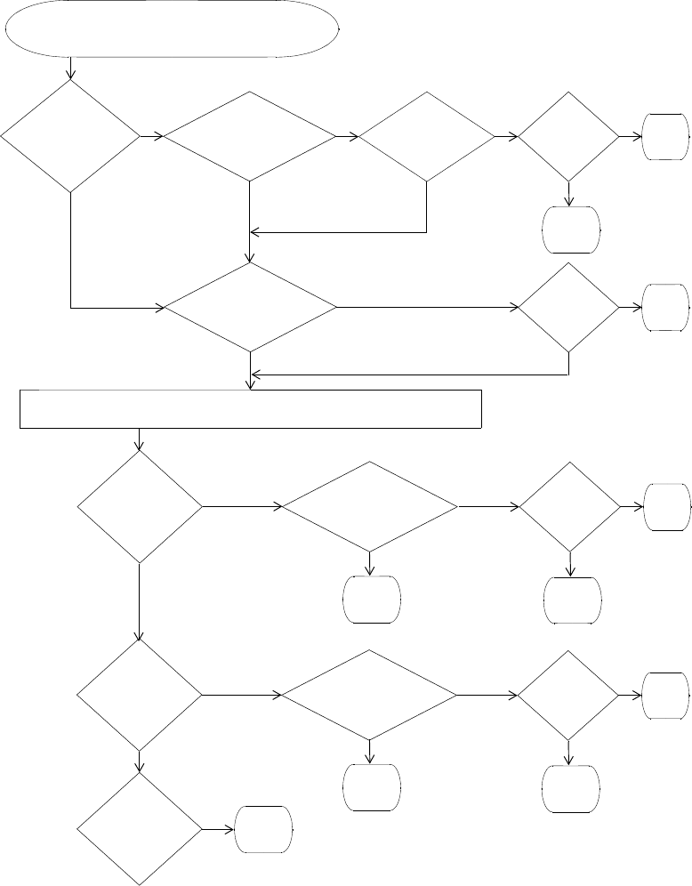
436 CHAPTER 21: CONFIGURING AAA FOR NETWORK USERS
Figure 30 Authentication Flowchart for Network Users
last-resort?
web?
none?
Client associates with MAP radio
or requests access from wired authentication port
Use fallthru authentication
Yes
No
Yes
Yes
Yes
Yes
No
Yes
Yes
No
No
No
No
Client requests
encrypted SSID?
Client
802.1X rule that
matches SSID? responds
Yes
MAC rule that
matches SSID?
No
to 802.1X?
Authent.
succeeds?
Allow
Client
Yes
Authent.
succeeds?
Allow
Client
Yes
Allow
Client
Refuse
Client
Refuse
Client
Last-resort rule that
matches SSID?
Web Auth rule that
matches SSID?
No
Refuse
Client
No
Authent.
succeeds? Yes
No
Refuse
Client
No
Refuse
Client
Allow
Client
Authent.
succeeds? Yes
No
Refuse
Client
About AAA for Network Users 437
SSID Name “Any”
In authentication rules for wireless access, you can specify the name any
for the SSID. This value is a wildcard that matches on any SSID string
requested by the user.
For 802.1X and WebAAA rules that match on SSID any, MSS checks the
RADIUS servers or local database for the username (and password, if
applicable) entered by the user. If the user information matches, MSS
grants access to the SSID requested by the user, regardless of which SSID
name it is.
For MAC authentication rules that match on SSID any, MSS checks the
RADIUS servers or local database for the MAC address (and password, if
applicable) of the user device. If the address matches, MSS grants access
to the SSID requested by the user, regardless of which SSID name it is.
Last-Resort Processing
One of the fallthru authentication types you can set on a service profile or
wired authentication port is last-resort.
If no 802.1X or MAC access rules are configured for a service profile’s
SSID, and the SSID’s fallthru type is last-resort, MSS allows users onto
the SSID or port without prompting for a username or password. The
default authorization attributes set on the SSID are applied to the user.
For example, if the vlan-name attribute on the service profile is set to
guest-vlan, last-resort users are placed in guest-vlan.
If no 802.1X or MAC access rules are configured for wired, and the wired
authentication port’s fallthru type is last-resort, MSS allows users onto
the port without prompting for a username or password. The
authorization attributes set on user last-resort-wired are applied to the user.
User Credential Requirements
The user credentials that MSS checks for on RADIUS servers or in the local
database differ depending on the type of authentication rule that
matches on the SSID or wired access requested by the user.
For a user to be successfully authenticated by an 802.1X or WebAAA
rule, the username and password entered by the user must be
configured on the RADIUS servers used by the authentication rule or
in the WX local database, if the local database is used by the rule.
438 CHAPTER 21: CONFIGURING AAA FOR NETWORK USERS
For a user to be successfully authenticated based on the MAC address
of the user device, the MAC address must be configured on the
RADIUS servers used by the authentication rule or in the WX local
database, if the local database is used by the rule. If the MAC address
is configured in the local database, no password is required. However,
since RADIUS requires a password, if the MAC address is on the
RADIUS server, MSS checks for a password. By default, MSS assumes
that the MAC address for a MAC user is also the password.
For a user to be successfully authenticated for last-resort access on a
wired authentication port, the RADIUS servers or local database must
contain a user named last-resort-wired. If the last-resort-wired user is
configured in the local database, no password is required. However,
since RADIUS requires a password, if the last-resort-wired user is on
the RADIUS server, MSS checks for a password. The default
well-known password is 3Com but is configurable. (The same
password applies to MAC users.)
Last-resort access to an SSID does not require a special user (such as
last-resort-ssid) to be configured. Instead, if the fallthru authentication
type on the SSID’s service profile is set to last-resort, and the SSID
does not have any 802.1X or MAC access rules, a user can access the
SSID without entering a username or password.
Authorization If the user is authenticated, MSS then checks the RADIUS server or local
database (the same place MSS looked for user information to
authenticate the user) for the authorization attributes assigned to the
user. Authorization attributes specify the network resources the user can
access.
The only required attribute is the Virtual LAN (VLAN) name on which to
place the user. RADIUS and MSS have additional optional attributes. For
example, you can provide further access controls by specifying the times
during which the user can access the network, you can apply inbound
and outbound access control lists (ACLs) to the user traffic, and so on.
To assign attributes on the RADIUS server, use the standard RADIUS
attributes supported on the server. To assign attributes in the WX
switch’s local database, use the MSS vendor-specific attributes (VSAs).
The RADIUS attributes supported by MSS are described in Appendix C,
“Supported RADIUS Attributes” on page 651.
About AAA for Network Users 439
MSS provides the following VSAs, which you can assign to users
configured in the local database or on a RADIUS server:
Encryption-Type — Specifies the type of encryption required for
access by the client. Clients who attempt to use an unauthorized
encryption method are rejected.
End-Date — Date and time after which the user is no longer allowed
to be on the network.
Mobility-Profile — Controls the WX switch ports a user can access.
For wireless users, an MSS Mobility Profile specifies the MAPs through
which the user can access the network. For wired authentication
users, the Mobility Profile specifies the wired authentication ports
through which the user can access the network.
SSID — SSID the user is allowed to access after authentication.
Start-Date — Date and time at which the user becomes eligible to
access the network. MSS does not authenticate the user unless the
attempt to access the network occurs at or after the specified date
and time, but before the end-date (if specified).
Time-of-Day — Day(s) and time(s) during which the user is permitted
to log into the network.
URL — URL to which the user is redirected after successful WebAAA.
VLAN-Name — VLAN to place the user on.
You also can assign the following RADIUS attributes to users configured
in the local database.
Filter-Id — Security ACL that permits or denies traffic received by
(input) or sent by (output) the user.
Service-Type — Type of access the user is requesting, which can be
network access, administrative access to the enabled (configuration)
mode of the MSS CLI, or administrative access to the nonenabled
mode of the CLI
Session-Timeout — Maximum number of seconds allowed for the
user session.
Regardless of whether you configure the user and attributes on RADIUS
servers or the WX local database, the VLAN attribute is required. The
other attributes are optional.
440 CHAPTER 21: CONFIGURING AAA FOR NETWORK USERS
In addition to configuring authorization attributes for users on RADIUS
servers or the WX local database, you can also configure attributes within
a service profile. These authorization attributes are applied to users
accessing the SSID managed by the service profile (in addition to any
attributes supplied by a RADIUS server or the WX local database).
Accounting MSS also supports accounting. Accounting collects and sends
information used for billing, auditing, and reporting — for example, user
identities, connection start and stop times, the number of packets
received and sent, and the number of bytes transferred. You can track
sessions through accounting information stored locally or on a remote
RADIUS server. As network users roam throughout a Mobility Domain,
accounting records track them and their network usage.
Summary of AAA
Features
Depending on your network configuration, you can configure
authentication, authorization, and accounting (AAA) for network users to
be performed locally on the WX switch or remotely on a RADIUS server.
The number of users that the local WX database can support depends on
your platform.
AAA for network users controls and monitors their use of the network:
Classification for customized access. As with administrative and
console users, you can classify network users through username
globbing. Based on the structured username, different AAA
treatments can be given to different classes of user. For example,
users in the human resources department can be authenticated
differently from users in the sales department.
Authentication for full or limited access. IEEE 802.1X network
users are authenticated when they identify themselves with a
credential. Authentication can be passed through to RADIUS,
performed locally on the WX switch, or only partially “offloaded” to
the switch. Network users without 802.1X support can be
authenticated by the MAC addresses of their devices. If neither
802.1X nor MAC authentication apply to the user, they can still be
authenticated by a fallthru method, either WebAAA or last-resort
authentication. Optionally, you can disable the fallthru option by
setting the fallthru type to none.

AAA Tools for Network Users 441
Authorization for access control. Authorization provides access
control by means of such mechanisms as per-user security access
control lists (ACLs), VLAN membership, Mobility Domain assignment,
and timeout enforcement. Because authorization is always performed
on network access users so they can use a particular VLAN, the WX
automatically uses the same AAA method (RADIUS server group or
local database) for authorization that you define for a user
authentication.
Local authorization control. You can override any AAA assignment
of VLAN or security ACL for individual network users on a particular
WX switch by configuring the location policy on the WX.
SSID default authorization attributes. You can configure service
profiles with a set of default AAA authorization attributes that are
used when the normal AAA process or a location policy does not
provide them.
Accounting for tracking users and resources. Accounting collects
and sends information used for billing, auditing, and reporting — for
example, user identities, connection start and stop times, the number
of packets received and sent, and the number of bytes transferred.
You can track sessions through accounting information stored locally
or on a remote RADIUS server. As network users roam throughout a
Mobility Domain, accounting records track them and their network
usage.
AAA Tools for
Network Users
Authentication verifies network user identity and is required before a
network user is granted access to the network. A WX switch
authenticates user identity by username-password matching, digital
signatures and certificates, or other methods (for example, by MAC
address).
You must decide whether to authenticate network users locally on the
WX, remotely via one or more external RADIUS server groups, or both
locally and remotely. (For server group details, see “Configuring RADIUS
Server Groups” on page 524.)
442 CHAPTER 21: CONFIGURING AAA FOR NETWORK USERS
“Globs” and Groups
for Network User
Classification
“Globbing” lets you classify users by username or MAC address for
different AAA treatments. A user glob is a string used by AAA and IEEE
802.1X or WebAAA methods to match a user or set of users. MAC
address globs match authentication methods to a MAC address or set of
MAC addresses. User globs and MAC address globs can make use of
wildcards. For details, see “User Globs, MAC Address Globs, and VLAN
Globs” on page 30.
A user group is a named collection of users or MAC addresses sharing a
common authorization policy. For example, you might group all users on
the first floor of building 17 into the group bldg-17-1st-floor, or group all
users in the IT group into the group infotech-people.
Wildcard “Any” for SSID Matching
Authentication rules for wireless access include the SSID name, and must
match on the SSID name requested by the user for MSS to attempt to
authenticate the user for that SSID. To make an authentication rule
match an any SSID string, specify the SSID name as any in the rule.
AAA Methods for
IEEE 802.1X and Web
Network Access
The following AAA methods are supported by 3Com for 802.1X and
Web network access mode:
Client certificates issued by a certificate authority (CA) for
authentication.
(For this method, you assign an authentication protocol to a user. For
protocol details, see “IEEE 802.1X Extensible Authentication Protocol
Types” on page 446.)
The WX local database of usernames and user groups for
authentication.
(For configuration details, see “Adding and Clearing Local Users for
Administrative Access” on page 59, “Authenticating via a Local
Database” on page 450, and “Adding and Clearing MAC Users and
User Groups Locally” on page 456.)
A named group of RADIUS servers. The WX switch supports up to four
server groups, which can each contain between one and four servers.
(For server group details, see “Configuring RADIUS Server Groups” on
page 524.)

AAA Tools for Network Users 443
You can use the local database or RADIUS servers for MAC access as well.
If you use RADIUS servers, make sure you configure the password for the
MAC address user as 3Com. (This is the default authorization password.
To change it, see “Changing the MAC Authorization Password for
RADIUS” on page 459.)
AAA Rollover Process
A WX switch attempts AAA methods in the order in which they are
entered in the configuration:
1The first AAA method in the list is used unless that method results in an
error. If the method results in a pass or fail, the result is final and the WX
tries no other methods.
2If the WX switch receives no response from the first AAA method, it tries
the second method in the list.
3If the WX switch receives no response from the second AAA method, it
tries the third method. This evaluation process is applied to all methods in
the list.
If a AAA rule specifies local as a secondary AAA method, to be used if the
RADIUS servers are unavailable, and MSS authenticates a client with the
local method, MSS starts again at the beginning of the method list when
attempting to authorize the client. This can cause unexpected delays
during client processing and can cause the client to time out before
completing logon.
Local Override Exception
The one exception to the operation described in “AAA Rollover Process”
takes place if the local database is the first method in the list and is
followed by a RADIUS server group method. If the local method fails to
find a matching username entry in the local database, the WX switch tries
the next RADIUS server group method. This exception is referred to as
local override.
If the local database is the last method in the list, however, local
authentication must either accept or deny the user, because it has no
other method to roll over to.
444 CHAPTER 21: CONFIGURING AAA FOR NETWORK USERS
Remote Authentication with Local Backup
You can use a combination of authentication methods; for example,
PEAP offload and local authentication. When PEAP offload is configured,
the WX switch offloads all EAP processing from server groups; the
RADIUS servers are not required to communicate using the EAP
protocols. (For details, see “Configuring EAP Offload” on page 449.) In
the event that RADIUS servers are unavailable, local authentication takes
place, using the database on the WX switch.
Suppose an administrator wants to rely on RADIUS servers and also wants
to ensure that a certain group of users always gets access. As shown in
the following example, the administrator can enable PEAP offload, so
that authentication is performed by a RADIUS server group as the first
method for these users, and configure local authentication last, in case
the RADIUS servers are unavailable. (See Figure 31.)
1To configure server-1 and server-2 at IP addresses 192.168.253.1 and
192.168.253.2 with the password chey3nn3, the administrator enters
the following commands:
WX1200# set radius server server-1 address 192.168.253.1 key chey3nn3
WX1200# set radius server server-2 address 192.168.253.2 key chey3nn3
2To configure server-1 and server-2 into server-group-1, the administrator
enters the following command:
WX1200# set server group server-group-1 members server-1 server-2
3To enable PEAP offload plus local authentication for all users of SSID
mycorp at @example.com, the administrator enters the following
command.
WX1200# set authentication dot1x ssid mycorp *@example.com pass-through
server-group-1 local
AAA Tools for Network Users 445
Figure 31 shows the results of this combination of methods.
Figure 31 Remote Authentication with PEAP Offload using Local Authentication
as Backup
Authentication proceeds as follows:
1When user Jose@example.com attempts authentication, the WX switch
sends an authentication request to the first AAA method, which is
server-group-1.
Because server-group-1 contains two servers, the first RADIUS server,
server-1, is contacted. If this server responds, the authentication proceeds
using server-1.
2If server-1 fails to respond, the WX retries the authentication using
server-2. If server-2 responds, the authentication proceeds using server-2.
3If server-2 does not respond, because the WX switch has no more servers
to try in server-group-1, the WX attempts to authenticate using the next
AAA method, which is the local method.
4The WX switch consults its local database for an entry that matches
Jose@example.com.
5If a suitable local database entry exists, the authentication proceeds. If
not, authentication fails and Jose@example.com is not allowed to access
the network.
RADIUS
Server-1
Server-group-1
RADIUS
Server-2
WX switch
local database
pass fail
set authentication dot1x ssid mycorp *@example.com pass-through server-group-1 local
1
1 2 3
4
5

446 CHAPTER 21: CONFIGURING AAA FOR NETWORK USERS
If one of the RADIUS servers in the group does respond, but it indicates
that the user does not exist on the RADIUS server, or that the user is not
permitted on the network, then authentication for the user fails,
regardless of any additional methods. Only if all the RADIUS servers in the
server group do not respond does the WX attempt to authenticate using
the next method in the list.
Also note that if the primary authentication method is local and the
secondary method is RADIUS, but the user does not exist in the local
database, then the WX does attempt to authenticate using RADIUS. See
“Local Override Exception” on page 443.
Using pass-through authentication as the primary authentication method and
the local database as the secondary authentication method is not supported.
IEEE 802.1X
Extensible
Authentication
Protocol Types
Extensible Authentication Protocol (EAP) is a generic point-to-point
protocol that supports multiple authentication mechanisms. EAP has
been adopted as a standard by the Institute of Electrical and Electronic
Engineers (IEEE). IEEE 802.1X is an encapsulated form for carrying
authentication messages in a standard message exchange between a user
(client) and an authenticator.
Table 38 summarizes the EAP protocols (also called types or methods)
supported by MSS.
Table 38 EAP Authentication Protocols for Local Processing
EAP Type Description Use Considerations
EAP-MD5
(EAP with
Message Digest
Algorithm 5)
Authentication algorithm
that uses a
challenge-response
mechanism to compare
hashes
Wired
authentication only*
This protocol
provides no
encryption or key
establishment.
EAP-TLS
(EAP with
Transport Layer
Security)
Protocol that provides
mutual authentication,
integrity-protected
encryption algorithm
negotiation, and key
exchange. EAP-TLS
provides encryption and
data integrity checking for
the connection.
Wireless and wired
authentication.
All authentication is
processed on the
WX switch.
This protocol
requires X.509
public key
certificates on
both sides of
the connection.
Requires use of
local database.
Not supported
for RADIUS.

AAA Tools for Network Users 447
Ways a WX Switch
Can Use EAP
Network users with 802.1X support cannot access the network unless they
are authenticated. You can configure a WX switch to authenticate users
with EAP on a group of RADIUS servers and/or in a local user database on
the WX, or to offload some authentication tasks from the server group.
Table 39 details these three basic WX authentication approaches.
(For information about digital certificates, see Chapter 20, “Managing
Keys and Certificates,” on page 413.)
PEAP-MS-
CHAP-V2
(Protected EAP
with Microsoft
Challenge
Handshake
Authentication
Protocol
version 2)
The wireless client
authenticates the server
(either the WX switch or a
RADIUS server) using TLS
to set up an encrypted
session. Mutual
authentication is
performed by
MS-CHAP-V2.
Wireless and wired
authentication:
The PEAP
portion is
processed on the
WX switch.
The
MS-CHAP-V2
portion is
processed on the
RADIUS server or
locally,
depending on
the
configuration.
Only the server
side of the
connection
requires a
certificate.
The client needs
only a username
and password.
* EAP-MD5 does not work with Microsoft wired authentication clients.
Table 38 EAP Authentication Protocols for Local Processing (continued)
EAP Type Description Use Considerations
Table 39 Three Basic WX Approaches to EAP Authentication
Approach Description
Pass-through An EAP session is established directly between the client and
RADIUS server, passing through the WX switch. User information
resides on the server. All authentication information and certificate
exchanges pass through the switch or use client certificates issued
by a certificate authority (CA). In this case, the switch does not
need a digital certificate, although the client might.
Local The WX switch performs all authentication using information in a
local user database configured on the switch, or using a
client-supplied certificate. No RADIUS servers are required. In this
case, the switch needs a digital certificate. If you plan to use the
EAP with Transport Layer Security (EAP-TLS) authentication
protocol, the clients also need certificates.
448 CHAPTER 21: CONFIGURING AAA FOR NETWORK USERS
Effects of
Authentication Type
on Encryption
Method
Wireless users who are authenticated on an encrypted service set
identifier (SSID) can have their data traffic encrypted by the following
methods:
Wi-Fi Protected Access (WPA) encryption
Non-WPA dynamic Wired Equivalent Privacy (WEP) encryption
Non-WPA static WEP encryption
(For encryption details, see Chapter 13, “Configuring User Encryption,”
on page 281.)
The authentication method you assign to a user determines the
encryption available to the user. Users configured for EAP authentication,
MAC authentication, Web, or last-resort authentication can have their
traffic encrypted as shown in Table 40.
Wired users are not eligible for the encryption performed on the traffic of
wireless users, but they can be authenticated by an EAP method, a MAC
address, or a Web login page served by the WX switch.
Offload The WX switch offloads all EAP processing from a RADIUS server by
establishing a TLS session between the switch and the client. In this
case, the switch needs a digital certificate. When you use offload,
RADIUS can still be used for non-EAP authentication and
authorization.
Table 39 Three Basic WX Approaches to EAP Authentication (continued)
Approach Description
Table 40 Encryption Available to Various Authentication Methods
Eap
Authentication
MAC
Authentication Last-Resort WebAAA
WPA encryption Static WEP Static WEP Static WEP
Dynamic WEP
encryption No encryption
(if SSID is
unencrypted)
No encryption
(if SSID is
unencrypted)
No encryption
(if SSID is
unencrypted)

Configuring 802.1X Authentication 449
Configuring 802.1X
Authentication
The IEEE 802.1X standard is a framework for passing EAP protocols over
a wired or wireless LAN. Within this framework, you can use TLS,
PEAP-TTLS, or EAP-MD5. Most EAP protocols can be passed through the
WX switch to the RADIUS server. Some protocols can be processed locally
on the WX switch.
The following 802.1X authentication command allows differing
authentication treatments for multiple users:
set authentication dot1x {ssid ssid-name | wired} user-glob
[bonded] protocol method1 [method2] [method3] [method4]
For example, the following command authenticates wireless user Tamara,
when requesting SSID wetlands, as an 802.1X user using the
PEAP-MS-CHAP-V2 method via the server group shorebirds, which
contains one or more RADIUS servers:
WX1200# set authentication dot1x ssid wetlands Tamara
peap-mschapv2 shorebirds
When a user attempts to connect through 802.1X, the following events
occur:
1For each 802.1X login attempt, MSS examines each command in the
configuration file in strict configuration order.
2The first command whose SSID and user glob matches the SSID and
incoming username is used to process this authentication. The command
determines exactly how this particular login attempt is processed by the
WX switch.
(For more information about user globs, see “User Globs” on page 30.)
Configuring EAP
Offload
You can configure the WX switch to offload all EAP processing from
server groups. In this case, the RADIUS server is not required to
communicate using the EAP protocols.
For PEAP-MS-CHAP-V2 offload, you define a complete user profile in the
local WX database and only a username and password on a RADIUS
server.
450 CHAPTER 21: CONFIGURING AAA FOR NETWORK USERS
For example, the following command authenticates all wireless users who
request SSID marshes at example.com by offloading PEAP processing
onto the WX switch, while still performing MS-CHAP-V2 authentication
via the server group shorebirds:
WX1200# set authentication dot1x ssid marshes *@example.com
peap-mschapv2 shorebirds
To offload both PEAP and MS-CHAP-V2 processing onto the WX switch,
use the following command:
WX1200# set authentication dot1x ssid marshes *@example.com
peap-mschapv2 local
Using Pass-Through The pass-through method causes EAP authentication requests to be
processed entirely by remote RADIUS servers in server groups.
For example, the following command enables users at EXAMPLE to be
processed via server group shorebirds or swampbirds:
WX1200# set authentication dot1X ssid marshes EXAMPLE/*
pass-through shorebirds swampbirds
The server group swampbirds is contacted only if all the RADIUS servers in
shorebirds do not respond.
(For an example of the use of pass-through servers plus the local
database for authentication, see “Remote Authentication with Local
Backup” on page 444.)
Authenticating via a
Local Database
To configure the WX switch to authenticate and authorize a user against
the local database in the WX switch, use the following command:
set authentication dot1x {ssid ssid-name | wired} user-glob
[bonded] protocol local
For example, the following command authenticates 802.1X user Jose for
wired authentication access via the local database:
WX1200# set authentication dot1X Jose wired
peap-mschapv2 local
success: change accepted.

Configuring 802.1X Authentication 451
Binding User
Authentication to
Machine
Authentication
Bonded Auth™ (bonded authentication) is a security feature that binds
an 802.1X user authentication to authentication of the machine from
which the user is attempting to log on. When this feature is enabled, MSS
authenticates the user only if the machine the user is on has already been
authenticated.
By default, MSS does not bind user authentication to machine
authentication. A trusted user can log on from any machine attached to
the network.
You can use bonded authentication with Microsoft Windows clients that
support separate 802.1X authentication for the machine itself and for a
user who uses the machine to log on to the network.
Network administrators sometimes use machine authentication in a
Microsoft Active Directory domain to run login scripts, and to control
defaults, application access and updates, and so on. Bonded
authentication provides an added security measure, by ensuring that a
trusted user can log onto the network only from a trusted machine
known to Active Directory.
For example, if user bob.mycorp.com has a trusted laptop PC used for
work but also has a personal laptop PC, you might want to bind Bob’s
authentication with the authentication of his workplace laptop,
host/bob-laptop.mycorp.com. In this case, Bob can log on to the
company network only from his work laptop.
When bonded authentication is enabled, MSS retains information about
the machine session when a user logs on from that machine. MSS
authenticates the user only if there has already been a successful machine
authentication. Evidence of the machine session in MSS indicates that the
machine has successfully authenticated and is therefore trusted by MSS.
If MSS does not have session information for the machine, MSS refuses to
authenticate the user and does not allow the user onto the network from
the unauthenticated machine.
If the 802.1X reauthentication parameter or the RADIUS Session-Timeout
parameter is applicable, the user must log in before the 802.1X
reauthentication timeout or the RADIUS session-timeout for the
machine’s session expires. Normally, these parameters apply only to
clients that use dynamic WEP, or use WEP-40 or WEP-104 encryption
with WPA or RSN.
452 CHAPTER 21: CONFIGURING AAA FOR NETWORK USERS
Authentication Rule Requirements
Bonded authentication requires an 802.1X authentication rule for the
machine itself, and a separate 802.1X authentication rule for the user(s).
Use the bonded option in the user authentication rule, but not in the
machine authentication rule.
The authentication rule for the machine must be higher up in the list of
authentication rules than the authentication rule for the user.
You must use 802.1X authentication rules. The 802.1X authentication
rule for the machine must use pass-through as the protocol. 3Com
recommends that you also use pass-through for the user authentication
rule.
The rule for the machine and the rule for the user must use a RADIUS
server group as the method. (Generally, in a bonded authentication
configuration, the RADIUS servers will use a user database stored on an
Active Directory server.)
(For a configuration example, see “Bonded Auth Configuration Example”
on page 454.)
3Com recommends that you make the rules as general as possible. For
example, if the Active Directory domain is mycorp.com, the following
userglobs match on all machine names and users in the domain:
host/*.mycorp.com (userglob for the machine authentication rule)
*.mycorp.com (userglob for the user authentication rule)
If the domain name has more nodes (for example, nl.mycorp.com), use
an asterisk in each node that you want to match globally. For example, to
match on all machines and users in mycorp.com, use the following
userglobs:
host/*.*.mycorp.com (userglob for the machine authentication rule)
*.*.mycorp.com (userglob for the user authentication rule)
Use more specific rules to direct machines and users to different server
groups. For example, to direct users in nl.mycorp.com to a different
server group than users in de.mycorp.com, use the following userglobs:
Configuring 802.1X Authentication 453
host/*.nl.mycorp.com (userglob for the machine authentication rule)
*.nl.mycorp.com (userglob for the user authentication rule)
host/*.de.mycorp.com (userglob for the machine authentication rule)
*.de.mycorp.com (userglob for the user authentication rule)
Bonded Auth Period
The Bonded Auth period is the number of seconds MSS allows a Bonded
Auth user to reauthenticate.
After successful machine authentication, a session for the machine
appears in the session table in MSS. When the user logs on and is
authenticated, the user session replaces the machine session in the table.
However, since the user authentication rule contains the bonded option,
MSS remembers that the machine was authenticated.
If a Bonded Auth user session is ended due to 802.1X reauthentication or
the RADIUS Session-Timeout parameter, MSS can allow time for the user
to reauthenticate. The amount of time that MSS allows for
reauthentication is controlled by the Bonded Auth period.
If the user does not reauthenticate within the Bonded Auth period, MSS
deletes the information about the machine session. After the machine
session information is deleted, the Bonded Auth user cannot
reauthenticate. When this occurs, the user will need to log off, then log
back on, to access the network. After multiple failed reauthentication
attempts, the user might need to reboot the PC before logging on.
By default, the Bonded Auth period is 0 seconds. MSS does not wait for a
Bonded Auth user to reauthenticate.
You can set the Bonded Auth period to a value up to 300 seconds. 3Com
recommends that you try 60 seconds, and change the period to a longer
value only if clients are unable to authenticate within 60 seconds.
To set the Bonded Auth period, use the following command:
set dot1x bonded-period seconds
To reset the Bonded Auth period to its default value (0), use the following
command:
clear dot1x bonded-period
454 CHAPTER 21: CONFIGURING AAA FOR NETWORK USERS
Bonded Auth Configuration Example
To configure Bonded Auth:
Configure separate authentication rules for the machine and for the
user(s).
Set the Bonded Auth period.
Verify the configuration changes.
The following commands configure two 802.1X authentication rules for
access to SSID mycorp. The first rule is for authentication of all trusted
laptop PCs at mycorp.com (host/*-laptop.mycorp.com). The second rule
is for bonded authentication of all users at mycorp.com (*.mycorp.com).
Both rules use pass-through as the protocol, and use RADIUS server
group radgrp1.
WX1200# set authentication dot1x ssid mycorp
host/*-laptop.mycorp.com pass-through radgrp1
success: change accepted.
WX1200# set authentication dot1x ssid mycorp *.mycorp.com
bonded pass-through radgrp1
success: change accepted.
The following command sets the Bonded Auth period to 60 seconds, to
allow time for WEP users to reauthenticate:
WX1200# set dot1x bonded-period 60
success: change accepted.
Displaying Bonded Auth Configuration Information
To display Bonded Auth configuration information, use the following command:
display dot1x config
Configuring 802.1X Authentication 455
In the following example, bob.mycorp.com uses Bonded Auth, and the
Bonded Auth period is set to 60 seconds.
WX1200# display dot1x config
802.1X user policy
----------------------
'host/bob-laptop.mycorp.com' on ssid 'mycorp' doing PASSTHRU
'bob.mycorp.com' on ssid 'mycorp' doing PASSTHRU (bonded)
802.1X parameter setting
---------------- -------
supplicant timeout 30
auth-server timeout 30
quiet period 60
transmit period 5
reauthentication period 3600
maximum requests 2
key transmission enabled
reauthentication enabled
authentication control enabled
WEP rekey period 1800
WEP rekey enabled
Bonded period 60
Information for the 802.1X authentication rule for the machine
(host/bob-laptop.mycorp.com) is also displayed. However, the bonded
option is configured only for the user authentication rule. The bonded
option applies only to the authentication rules for users, not the
authentication rules for machines.

456 CHAPTER 21: CONFIGURING AAA FOR NETWORK USERS
Configuring
Authentication and
Authorization by
MAC Address
You must sometimes authenticate users based on the MAC addresses of
their devices rather than a username-password or certificate. For
example, some Voice-over-IP (VoIP) phones and personal digital assistants
(PDAs) do not support 802.1X authentication. If a client does not support
802.1X, MSS attempts to perform MAC authentication for the client
instead. The WX switch can discover the MAC address of the device from
received frames and can use the MAC address in place of a username for
the client.
Users authorized by MAC address require a MAC authorization password
if RADIUS authentication is desired. By default, MSS assumes that the
MAC address for a MAC user is also the password.
CAUTION: Use this method with care. IEEE 802.11 frames can be forged
and can result in unauthorized network access if MAC authentication is
employed.
Adding and Clearing
MAC Users and User
Groups Locally
MAC users and groups can gain network access only through the WX
switch. They cannot create administrative connections to the WX switch.
A MAC user is created in a similar fashion to other local users except for
having a MAC address instead of a username. MAC user groups are
created in a similar fashion to other local user groups.
(To create a MAC user profile or MAC user group on a RADIUS server, see
the documentation for your RADIUS server.)
Adding MAC Users and Groups
To create a MAC user group in the local WX database, you must
associate it with an authorization attribute and value. Use the following
command:
set mac-usergroup group-name attr attribute-name value
For example, to create a MAC user group called mac-easters with a
3000-second Session-Timeout value, type the following command:
WX1200# set mac-usergroup mac-easters attr
session-timeout 3000
success: change accepted.
To configure a MAC user in the local database and optionally add the
user to a group, use the following command:
set mac-user mac-addr [group group-name]
Configuring Authentication and Authorization by MAC Address 457
For example, type the following command to add MAC user
01:0f:03:04:05:06 to group macfans:
WX1200# set mac-user 01:0f:03:04:05:06 group macfans
success: change accepted.
Clearing MAC Users and Groups
To clear a MAC user from a user group, use the following command:
clear mac-user mac-addr group
For example, the following command removes MAC user
01:0f:03:04:05:06 from group macfans:
WX1200# clear mac-user 01:0f:03:04:05:06 group
success: change accepted.
The clear mac-usergroup command removes the group.
To remove a MAC user profile from the local database on the WX switch,
type the following command:
clear mac-user mac-address
For example, the following command removes MAC user
01:0f:03:04:05:06 from the local database:
WX1200# clear mac-user 01:0f:03:04:05:06
success: change accepted.
Configuring MAC
Authentication and
Authorization
The set authentication mac command defines the AAA methods by
which MAC addresses can be used for authentication. You can configure
authentication for users through the MAC addresses of their devices with
the following command:
set authentication mac {ssid ssid-name | wired} mac-addr-glob
method1 [method2] [method3] [method4]
MAC addresses can be authenticated by either the WX local database or
by a RADIUS server group. For example, the following command sets the
authentication for MAC address 01:01:02:03:04:05 when requesting
SSID voice, via the local database:
WX1200# set authentication mac ssid voice
01:01:02:03:04:05 local
success: change accepted
458 CHAPTER 21: CONFIGURING AAA FOR NETWORK USERS
If the switch’s configuration does not contain a set authentication mac
command that matches a non-802.1X client’s MAC address, MSS tries
MAC authentication by default.
You can also glob MAC addresses. For example, the following command
locally authenticates all MAC addresses that begin with the octets
01:01:02:
WX1200# set authentication mac ssid voice 01:01:02:* local
success: change accepted
(For details about MAC address globs, see “MAC Address Globs” on
page 31.)
You can add authorization attributes to authenticated MAC users with
the following command:
set mac-user mac-addr attr attribute-name value
For example, to add the MAC user 00:01:02:03:04:05 to VLAN red:
WX1200# set mac-user 00:01:02:03:04:05 attr vlan-name red
success: change accepted
To change the value of an authorization attribute, reenter the command
with the new value. To clear an authorization attribute from a MAC user
profile in the local database, use the following command:
clear mac-user mac-addr attr attribute-name
For example, the following command clears the VLAN assignment from
MAC user 01:0f:02:03:04:05:
WX1200# clear mac-user 01:0f:03:04:05:06 attr vlan-name
success: change accepted.
(For a complete list of authorization attributes, see Table 43 on
page 488.)

Configuring Authentication and Authorization by MAC Address 459
Changing the MAC
Authorization
Password for RADIUS
When you enable MAC authentication, the client does not supply a
regular username or password. The MAC address of the user’s device is
extracted from frames received from the device.
To authenticate and authorize MAC users via RADIUS, MSS must supply a
password for MAC users, which is called the outbound authorization
password. By default, MSS sends the MAC user’s MAC address as that
user’s password too.
To set the authorization password to a specific value for all MAC users,
use the following command:
set radius server server-name author-password password
Before setting the outbound authorization password for a RADIUS server,
you must have set the address for the RADIUS server. For more
information, see “Configuring RADIUS Servers” on page 521.
For example, the following command sets the outbound authorization
password for MAC users on server bigbird to h00per:
WX1200# set radius server bigbird author-password h00per
success: change accepted.
If the MAC address is in the database, MSS uses the VLAN attribute and
other attributes associated with it for user authorization. Otherwise, MSS
tries the fallthru authentication type, which can be last-resort, Web, or
none.
A MAC address must be dash-delimited in the RADIUS database — for
example, 00-00-01-03-04-05. However, the MSS always displays
colon-delimited MAC addresses.
To reset the authorization password to the default (user’s MAC address),
clear the RADIUS server, then readd it without specifying the
authorization password. To clear a RADIUS server, use the clear radius
server server-name command.

460 CHAPTER 21: CONFIGURING AAA FOR NETWORK USERS
Configuring Web
Portal WebAAA
WebAAA simplifies secure access to unencrypted SSIDs. When a user
requests access to an SSID or attempts to access a web page before
logging onto the network, MSS serves a login page to the user’s browser.
After the user enters a username and password, MSS checks the local
database or RADIUS servers for the user information, and grants or denies
access based on whether the user information is found.
MSS redirects an authenticated user back to the requested web page, or
to a page specified by the administrator.
WebAAA, like other types of authentication, is based on an SSID or on a
wired authentication port.
You can use WebAAA on both encrypted and unencrypted SSIDs. If you
use WebAAA on an encrypted SSID, you can use static WEP or WPA with
PSK as the encryption type.
MSS provides a 3Com login page, which is used by default. You can add
custom login pages to the WX switch’s nonvolatile storage, and
configure MSS to serve those pages instead.
Web Portal WebAAA replaces the WebAAA implementation in MSS
Version 3.x. The previous implementation is deprecated beginning in MSS
Version 4.0. During upgrade from MSS Version 3.x, your 3.x WebAAA
configuration is automatically converted to a Web Portal WebAAA
configuration.
How WebAAA Portal
Works
1A WebAAA user attempts to access the network. For a wireless user, this
begins when the user’s network interface card (NIC) associates with an
SSID on a 3Com radio. For a wired authentication user, this begins when
the user’s NIC sends data on the wired authentication port.
2MSS starts a portal session for the user, and places the user in a VLAN.
If the user is wireless (associated with an SSID), MSS assigns the
user to the VLAN set by the vlan-name attribute for the SSID’s service
profile.
If the user is on a wired authentication port, the VLAN is the one
assigned to the web-portal-wired user.

Configuring Web Portal WebAAA 461
3The user opens a Web browser. The Web browser sends a DNS request
for the IP address of the home page or a URL requested by the user.
4MSS does the following:
Intercepts the DNS request, uses the MSS DNS proxy to obtain the URL
IP address from the network DNS server, and sends the address to the
user’s browser.
Serves a login page to the WebAAA user. (Also see “Display of the
Login Page” on page 461.)
5The user enters their username and password in the WebAAA login page.
6MSS authenticates the user by checking RADIUS or the switch’s local
database for the username and password entered by the user. If the user
information is present, MSS authorizes the user based on the
authorization attributes set for the user.
MSS ignores the VLAN-Name or Tunnel-Private-Group-ID attribute
associated with the user, and leaves the user in the VLAN associated with
the SSID’s service profile (if wireless) or with the web-portal-wired user (if
the user is on a wired authentication port).
7After authentication and authorization are complete, MSS changes the
user’s session from a portal session with the name web-portal-ssid or
web-portal-wired to a WebAAA session with the user’s name. The
session remains connected, but is now an identity-based session for the
user instead of a portal session.
8MSS redirects the browser to the URL initially requested by the user or, if
the URL VSA is configured for the user, redirects the user to the URL
specified by the VSA.
9The web page for the URL to which the user is redirected appears in the
user’s browser window.
Display of the Login Page
When a WebAAA client first tries to access a web page, the client’s
browser sends a DNS request to obtain the IP address mapped to the
domain name requested by the client’s browser. The WX proxies this DNS
request to the network’s DNS server, then proxies the reply back to the
client. If the DNS server has a record for the requested URL, the request is
successful and the WX serves a web login page to the client. However, if
the DNS request is unsuccessful, the WX displays a message informing
the user of this and does not serve the login page.

462 CHAPTER 21: CONFIGURING AAA FOR NETWORK USERS
If the WX does not receive a reply to a client’s DNS request, the WX
spoofs a reply to the browser by sending the WX switch’s own IP address
as the resolution to the browser’s DNS query. The WX also serves the web
login page. This behavior simplifies use of the WebAAA feature in
networks that do not have a DNS server. However, if the requested URL is
invalid, the behavior gives the appearance that the requested URL is valid,
since the browser receives a login page. Moreover, the browser might
cache a mapping of the invalid URL to the WX IP address.
If the user enters an IP address, most browsers attempt to contact the IP
address directly without using DNS. Some browsers even interpret
numeric strings as IP addresses (in decimal notation) if a valid address
could be formed by adding dots (dotted decimal notation). For example,
208194225132 would be interpreted as a valid IP address, when
converted to 208.194.225.132.
WebAAA
Requirements and
Recommendations
Use the following information to ensure operation of the WebAAA
feature.
MSS Version 5.0 does not require or support special user web-portal-ssid,
where ssid is the SSID the Web-Portal user associates with. Previous MSS
Versions required this special user for Web-Portal configurations. Any
web-portal-ssid users are removed from the configuration during
upgrade to MSS Version 5.0. However, the web-portal-wired user is still
required for Web Portal on wired authentication ports.
WX Switch Requirements
WebAAA certificate—A WebAAA certificate must be installed on the
switch. You can use a self-signed (signed by the WX) WebAAA
certificate automatically generated by MSS, manually generate a
self-signed one, or install one signed by a trusted third-party
certificate authority (CA). (For more information, see Chapter 20,
“Managing Keys and Certificates,” on page 413.)
If you choose to install a self-signed WebAAA certificate, use a
common name (a required field in the certificate), that resembles a
web address and contains at least one dot. When MSS serves the
login page to the browser, the page’s URL is based on the common
name in the WebAAA certificate.

Configuring Web Portal WebAAA 463
Here are some examples of common names in the recommended
format:
webaaa.login
webaaa.customername.com
portal.local
Here are some examples of common names that are not in the
recommended format:
webaaa
3Com_webaaa
webportal
User VLAN—An IP interface must be configured on the user’s VLAN.
The interface must be in the subnet on which the DHCP server will
place the user, so that the switch can communicate with both the
client and the client’s preferred DNS server. (To configure a VLAN, see
“Configuring and Managing VLANs” on page 87.)
If users will roam from the switch where they connect to the network
to other WX switches, the system IP addresses of the switches should
not be in the web-portal VLAN.
Although the SSID’s default VLAN and the user VLAN must be the
same, you can use a location policy on the switch where the service
profile is configured to move the user to another VLAN. The other
VLAN is not required to be statically configured on the switch. The
VLAN does have the same requirements as other user VLANs, as
described above. For example, the user VLAN on the roamed-to
switch must have an IP interface, the interface must be in the subnet
that has DHCP, and the subnet must be the same one the DHCP
server will place the user in.
In MSS Version 4.1 and earlier, the VLAN was required to be statically
configured on the WX switch where WebAAA was configured and
through which the user accessed the network. MSS Version 4.2 removes
this restriction. The VLAN you want to place an authenticated WebAAA
user on does not need to be statically configured on the switch where
Web Portal is configured. If the VLAN you assign to a user is not statically
configured on the VLAN where the user accesses the network, the switch
where the user accessed the network builds a tunnel to the switch where
the user’s VLAN is configured. That switch uses DHCP to assign an IP
address to the user.
464 CHAPTER 21: CONFIGURING AAA FOR NETWORK USERS
Fallthru authentication type—The fallthru authentication type for each
SSID and wired authentication port that you want to support
WebAAA, must be set to web-portal. The default authentication
type for wired authentication ports and for SSIDs is None (no fallthru
authentication is used).
To set the fallthru authentication type for an SSID, set it in the service
profile for the SSID, using the set service-profile auth-fallthru
command. To set it on a wired authentication port, use the auth-fall-thru
web-portal parameter of the set port type wired-auth command.
Authorization attributes—Wireless Web-Portal users get their
authorization attributes from the SSID’s service profile. To assign
wireless Web-Portal users to a VLAN, use the set service-profile
name attr vlan-name vlan-id command.
Web-Portal users on wired authentication ports get their authorization
attributes from the special user web-portal-wired. To assign wired
Web-Portal users to a VLAN, use the set user web-portal-wired attr
vlan-name vlan-id command. By default, web-portal-wired users
are assigned to the default VLAN.
Portal ACL (created by MSS automatically)—The portalacl ACL
captures all the portal user’s traffic except for DHCP traffic. The
portalacl has the following ACEs:
set security acl ip portalacl permit udp 0.0.0.0
255.255.255.255 eq 68 0.0.0.0 255.255.255.255 eq 67
set security acl ip portalacl deny 0.0.0.0 255.255.255.255
capture
MSS automatically creates the portalacl ACL the first time you set the
fallthru authentication type on any service profile or wired authentication
port to web-portal.
The ACL is mapped to wireless Web-Portal users through the service
profile. When you set the fallthru authentication type on a service
profile to web-portal, portalacl is set as the Web-Portal ACL. The ACL
is applied to a Web-Portal user’s traffic when the user associates with
the service profile’s SSID.
The ACL is mapped to Web-Portal users on a wired-authentication
port by the Filter-id.in attribute configured on the web-portal-wired
user. When you set the fallthru authentication type on a wired
authentication port to web-portal, MSS creates the web-portal-wired
user. MSS sets the filter-id attribute on the user to portalacl.in.

Configuring Web Portal WebAAA 465
CAUTION: Without the Web-Portal ACL, WebAAA users will be placed
on the network without any filters.
CAUTION: Do not change the deny rule at the bottom of the ACL. This
rule must be present and the capture option must be used with the rule.
If the rule does not have the capture option, the Web Portal user never
receives a login page. If you need to modify the Web-Portal ACL, create a
new one instead, and modify the service profile or web-portal-wired user
to use the new ACL.
Authentication rules—A web authentication rule must be configured
for the WebAAA users. The web rule must match on the username
the WebAAA user will enter on the WebAAA login page. (The match
can be on a userglob or individual username.) The web rule also must
match on the SSID the user will use to access the network. If the user
will access the network on a wired authentication port, the rule must
match on wired.
To configure authentication rules, use the set authentication web
command.
Web Portal WebAAA must be enabled, using the set web-portal
command. The feature is enabled by default.
Portal ACL and User ACLs
The portalacl ACL, which MSS creates automatically, applies only when a
user’s session is in the portal state. After the user is authenticated and
authorized, the ACL is no longer applicable.
To modify a user’s access while the user is still being authenticated and
authorized, you can configure another ACL and map that ACL instead to
the web-portal-ssid or web-portal-wired user. Make sure to use the
capture option for traffic you do not want to allow. 3Com recommends
that you do not change the portalacl ACL. Leave the ACL as a backup in
case you need to refer to it or you need to use it again.
For example, if you want to allow the user to access a credit card server
while MSS is still authenticating and authorizing the user, create a new
ACL, add ACEs that are the same as the ACEs in portalacl, and add a new
ACE before the last one, to allow access to the credit card server. Make
sure the last ACE in the ACL is the deny ACE that captures all traffic that
is not allowed by the other ACEs.

466 CHAPTER 21: CONFIGURING AAA FOR NETWORK USERS
To modify a WebAAA user’s access after the user is authenticated and
authorized, map an ACL to the individual WebAAA user. Changes you
make to the ACL mapped to the web-portal-ssid or web-portal-wired
user do not affect user access after authentication and authorization are
complete.
The filter-id attribute in a service profile applies only to authenticated
users. If this attribute is set in a service profile for an SSID accessed by
Web-Portal users, the attribute applies only after users have been
authenticated. While a Web-Portal user is still being authenticated, the
ACL set by the web-portal-acl applies instead.
Network Requirements
The VLAN where users will be placed must have an IP interface, and the
subnet the interface is in must have access to DHCP and DNS servers.
WX Switch Recommendations
Consider installing a WebAAA certificate signed by a trusted CA,
instead of one signed by the WX switch itself. Unless the client’s
browser is configured to trust the signature on the switch’s WebAAA
certificate, display of the login page can take several seconds longer
than usual, and might be interrupted by a dialog asking the user what
to do about the untrusted certificate. Generally, the browser is already
configured to trust certificates signed by a CA.
Client NIC Requirements
Configure the NIC to use DHCP to obtain its IP address.
Client Web Browser Recommendations
Use a well-known browser, such as Internet Explorer (Windows),
Firefox (Mozilla-based), or Safari (Macintosh)
If the WebAAA certificate on the WX switch is self-signed, configure
the browser to trust the signature by installing the certificate on the
browser, so that the browser does not display a dialog about the
certificate each time the user tries to log on.

Configuring Web Portal WebAAA 467
Configuring Web
Portal WebAAA
To configure Web Portal WebAAA:
1Configure an SSID or wired authentication port and set the fallthru
authentication type to web-portal. The default for SSIDs and for wired
authentication ports is none.
2Configure individual WebAAA users. Because the VLAN is assigned based
on the service profile (where it is set by the attr vlan-name vlan-id
option) or web-portal-wired user (where it is set to default), MSS
ignores the VLAN-Name and Tunnel-Private-Group-ID attributes.
However, MSS does assign other attributes if set.
3Configure web authentication rules for the WebAAA users.
4Save the configuration changes.
Web Portal WebAAA Configuration Example
This example configures Web-Portal access to SSID mycorp.
1Configure the user VLAN on ports 2 and 3, and configure an IP interface
on the VLAN:
WX1200# set vlan mycorp-vlan port 2-3
success: change accepted.
WX1200# set interface mycorp-vlan ip 192.168.12.10
255.255.255.0
success: change accepted.
The VLAN does not need to be configured on the switch where you
configure Web Portal but the VLAN does need to be configured on a
switch somewhere in the Mobility Domain. The user’s traffic will be
tunneled to the switch where the VLAN is configured.
2Configure the service profile for SSID mycorp. Configuration includes the
following:
Set the SSID name.
Change the fallthru authentication type to web-portal.
Set the default VLAN to mycorp-vlan (created in step 1.) MSS will
place Web-Portal users into this VLAN.
Enable RSN (WPA2) data encryption with CCMP. (This example
assumes clients support this encryption type.) TKIP is enabled by
default and is left enabled in this example.
WX1200# set service-profile mycorp-srvcprof ssid-name mycorp
success: change accepted.
468 CHAPTER 21: CONFIGURING AAA FOR NETWORK USERS
WX1200# set service-profile mycorp-srvcprof auth-fallthru
web-portal
success: change accepted.
WX1200# set service-profile mycorp-srvcprof attr vlan-name
mycorp-vlan
success: change accepted.
WX1200# set service-profile mycorp-srvcprof rsn-ie enable
success: change accepted.
WX1200# set service-profile mycorp-srvcprof cipher-ccmp
enable
success: change accepted.
3Display the service profile to verify the changes:
WX1200# display service-profile mycorp-srvcprof
ssid-name: mycorp ssid-type: crypto
Beacon: yes Proxy ARP: no
DHCP restrict: no No broadcast: no
Short retry limit: 5 Long retry limit: 5
Auth fallthru: none Sygate On-Demand (SODA): no
Enforce SODA checks: yes SODA remediation ACL:
Custom success web-page: Custom failure web-page:
Custom logout web-page: Custom agent-directory:
Static COS: no COS: 0
CAC mode: none CAC sessions: 14
User idle timeout: 180 Idle client probing: yes
Keep initial vlan: no Web Portal Session Timeout: 5
Web Portal ACL: portalacl
WEP Key 1 value: <none> WEP Key 2 value: <none>
WEP Key 3 value: <none> WEP Key 4 value: <none>
WEP Unicast Index: 1 WEP Multicast Index: 1
Shared Key Auth: NO
RSN enabled:
ciphers: cipher-tkip, cipher-ccmp
authentication: 802.1X
TKIP countermeasures time: 60000ms
vlan-name = mycorp-vlan
...
4Configure individual WebAAA users.
WX1200# set user alice password alicepword
success: change accepted.
WX1200# set user bob password bobpword
success: change accepted.
5Configure a web authentication rule for WebAAA users. The following
rule uses a wildcard (**) to match on all user names.
Configuring Web Portal WebAAA 469
The rule does not by itself allow access to all usernames. The ** value
simply makes all usernames eligible for authentication, in this case by
searching the switch’s local database for the matching usernames and
passwords. If a username does not match on the access rule’s userglob,
the user is denied access without a search of the local database for the
username and password.
WX4400# set authentication web ssid mycorp ** local
success: change accepted.
6Display the configuration:
WX1200# display config
# Configuration nvgen'd at 2006-6-13 13:27:07
# Image 5.0.0.0.62
# Model WXR100-2
# Last change occurred at 2006-6-13 13:24:46
...
set service-profile mycorp-srvcprof ssid-name mycorp
set service-profile mycorp-srvcprof auth-fallthru web-portal
set service-profile mycorp-srvcprof rsn-ie enable
set service-profile mycorp-srvcprof cipher-ccmp enable
set service-profile mycorp-srvcprof web-portal-acl portalacl
set service-profile mycorp-srvcprof attr vlan-name
mycorp-vlan
...
set authentication web ssid mycorp ** local
...
set user alice password encrypted 070e2d454d0c091218000f
set user bob password encrypted 110b16070705041e00
...
set radio-profile radprof1 service-profile mycorp-srvcprof
set ap 7 radio 2 radio-profile radprof1 mode enable
set ap 8 radio 2 radio-profile radprof1 mode enable
...
set vlan corpvlan port 2-3
set interface corpvlan ip 192.168.12.10 255.255.255.0
...
set security acl ip portalacl permit udp 0.0.0.0
255.255.255.255 eq 68 0.0.0.0 255.255.255.255 eq 67
set security acl ip portalacl deny 0.0.0.0 255.255.255.255
capture
commit security acl portalacl
470 CHAPTER 21: CONFIGURING AAA FOR NETWORK USERS
Displaying Session Information for Web Portal WebAAA Users
To display user session information for Web Portal WebAAA users, use
the following command:
display sessions network [user user-glob |
mac-addr mac-addr-glob | ssid ssid-name | vlan vlan-glob |
session-id session-id | wired] [verbose]
You can determine whether a Web Portal WebAAA user has completed
the authentication and authorization process, based on the username
displayed in the session table. The following command shows the
sessions for SSID mycorp.
WX4400# display sessions network ssid mycorp
User Sess IP or MAC VLAN Port/
Name ID Address Name Radio
------------------------------ ---- ----------------- --------------- -----
alice 4* 192.168.12.101 corpvlan 3/1
web-portal-mycorp 5 192.168.12.102 corpvlan 3/1
2 sessions total
This example shows two sessions. The session for alice has the user’s
name and is flagged with an asterisk ( * ). The asterisk indicates that the
user has completed authentication and authorization. The session for
web-portal-mycorp indicates that a WebAAA user is on the network but
is still being authenticated. The user alice has all the access privileges
configured for the user, whereas the user who is still on the portal session
with the name web-portal-mycorp has limited access to resources. By
default, this user can send and receive DHCP traffic only. Everything else
is captured by the web portal.
After authentication and authorization are complete, the
web-portal-mycorp username is replaced with the username entered by
the WebAAA user during login. The following example shows session
information for the same user, but after the user is authorized to access
resources on the network:
WX4400# display sessions network ssid mycorp
User Sess IP or MAC VLAN Port/
Name ID Address Name Radio
------------------------------ ---- ----------------- --------------- -----
alice 4* 192.168.12.101 corpvlan 3/1
bob 5* 192.168.12.102 corpvlan 3/1
2 sessions total
Configuring Web Portal WebAAA 471
Using a Custom Login
Page
By default, MSS serves the 3Com login page for Web login.
To serve a custom page instead, do the following:
1Copy and modify the 3Com page, or create a new page.
2Create a subdirectory in the user files area of the WX switch’s nonvolatile
storage, and copy the custom page into the subdirectory.
3Configure SSIDs and wired authentication ports to use the custom form,
by specifying the location of the form.
To serve a custom login page to wired authentication users, you must
create a web subdirectory and save the custom page in this directory.

472 CHAPTER 21: CONFIGURING AAA FOR NETWORK USERS
MSS uses the following process to find the login page to display to a user:
If the user is attempting to access an SSID and a custom page is
specified in the service profile, MSS serves the custom page.
If the switch nonvolatile storage has a page in web named
wba_form.html (web/wba_form.html), MSS serves this page. This
applies to all wired authentication users. The wba_form.html page
also is served to SSID users if the SSID service profile does not specify a
custom page.
If there is no wba_form.html page and no custom page in the SSID
service profile, MSS serves the default page.
Copying and Modifying the Web Login Page
To copy and modify the 3Com Web login page:
1Configure an unencrypted SSID on a WX switch. The SSID is temporary
and does not need to be one you intend to use in your network. To
configure the SSID, use the following commands:
set service-profile name ssid-name ssid-name
set service-profile name ssid-type clear
set service-profile name auth-fallthru web-portal
set radio-profile name service-profile name
set ap apnumber radio {1 | 2} radio-profile name mode enable
Use the first two commands to configure a temporary SSID and
temporary radio profile. Use the last command to map the temporary
radio profile with the disabled radio, and enable the radio.
If the radio you plan to use is already in service, you need to disable the
radio profile the radio is in and remove the radio from the profile.
2From your PC, attempt to access the temporary SSID. The WX switch
should serve the login page.
3Use your browser to save a copy of the page.
4Use a Web page editor or text editor to modify the page title, greeting,
logo, and warning text. Be sure that the <form> HTML tag has the
following format: <form name=”weblogin” method=”post” action=””>.
Earlier versions of MSS present a page using the form tag. More recent
versions of MSS automatically populate the action parameter with an
HTTPS URL in order to defer the SSL transaction to the actual posting of
the form. This URL must be removed from the action parameter in your
custom page so that the format matches the <form name=”weblogin”
method=”post” action=””> format exactly.

Configuring Web Portal WebAAA 473
5Save the modified page.
Filenames and paths for image source files must be relative to the HTML
page. For example, if login page mycorp-login.html and image file
mylogo.gif are located in subdirectory mycorp/, specify the image source
as mylogo.gif, not mycorp/mylogo.gif.
It is recommended to keep the form as simple as possible with a
minimum number of graphics to display.
Custom Login Page Scenario
The following steps illustrate how to create a custom page:
1Perform following on the WX switch:
aCreate a temporary service profile and configure a temporary, clear
SSID on it:
WX1200# set service-profile tempsrvc ssid-name tempssid
success: change accepted.
WX1200# set service-profile tempsrvc ssid-type clear
success: change accepted.
WX1200# set service-profile tempsrvc auth-fallthru web-portal
success: change accepted.
bCreate a temporary radio profile and map the temporary service
profile to it:
WX1200# set radio-profile temprad service-profile tempsrvc
success: change accepted.
cMap a radio to the temporary radio profile and enable it:
WX1200# set ap 2 radio 1 radio-profile temprad mode enable
success: change accepted.
2From your PC, attempt to access the temporary SSID. The WX switch
displays the login page.
3In the browser, select File > Save As to save the login page.
4Edit the login page:
aChange the page title:
<TITLE>My Corp webAAA</TITLE>
bChange the logo:
<img src="mylogo.gif" width="143" height="65" border="0"
alt="Company Logo">

474 CHAPTER 21: CONFIGURING AAA FOR NETWORK USERS
cChange the greeting:
<h3>Welcome to Mycorp’s Wireless LAN</h3>
dChange the warning statement if desired:
<B>WARNING:</B>
My corp’s warning text.
eDo not change the form (delimited by the <form name=> and </form>
tags. The form values are required for the page to work properly.
3Com recommends using an HTML editor that preserves the original
HTML code rather than reformatting the entire document. If the section
of the page between <!-- DO_NOT_MODIFY_THE_SOURCE_BEGIN -->
and <!--END DO_NOT_MODIFY_THE_SOURCE--> is modified manually or
by your HTML editing application, the page should be thoroughly tested
prior to deploying it on your network and after every MSS software
upgrade.
5Save the modified page.
6On the WX switch, create a new subdirectory for the customized page.
(The files must be on a TFTP server that the WX switch can reach over the
network.)
WX1200# mkdir mycorp-webaaa
success: change accepted.
7Copy the files for the customized page into the subdirectory:
WX1200# copy tftp://10.1.1.1/mycorp-login.html mycorp-webaaa/mycorp-login.html
success: received 637 bytes in 0.253 seconds [ 2517 bytes/sec]
WX1200# copy tftp://10.1.1.1/mylogo.gif mycorp-webaaa/mylogo.gif
success: received 1202 bytes in 0.402 seconds [ 2112 bytes/sec]
WX1200# dir mycorp-webaaa
===============================================================================
file:
Filename Size Created
file:mycorp-login.html 637 bytes Aug 12 2004, 15:42:26
file:mylogo.gif 1202 bytes Aug 12 2004, 15:57:11
Total: 1839 bytes used, 206577 Kbytes free
8Use the following command to configure the SSID to use the custom
page:
set service-profile name web-portal-form url

Configuring Web Portal WebAAA 475
For the url, specify the full path; for example,
mycorp-webaaa/mycorp-login.html. If the custom login page includes
*.gif or *.jpg images, their path names are interpreted relative to the
directory from which the page is served.
9Configure WebAAA users and rules as described in “Configuring Web
Portal WebAAA” on page 460.
Using Dynamic Fields
in WebAAA Redirect
URLs
You can include variables in the URL to which a WebAAA client is
redirected after authentication and authorization. Table 41 lists the
variables you can include in a redirect URL.
A URL string can also contain the literal characters $ and ?, if you use the
values listed in Table 42.
You can configure a redirect URL for a group of users or for an individual
user. For example, the following command configures a redirect URL
containing a variable for the username:
WX1200# set usergroup ancestors attr url http://myserver.com/$u.html
success: change accepted.
The variable applies to all WebAAA users in user group ancestors. When
user zinjanthropus is successfully authenticated and authorized, MSS
redirects the user to the following URL:
http://myserver.com/zinjanthropus.html
Table 41 Variables for Redirect URLs
Variable Description
$u Username of the WebAAA user
$v VLAN to which the user was assigned during
authorization
$s SSID the user is on
$p Name of the service profile that manages the
parameters for the SSID
Table 42 Values for Literal Characters
Variable Description
$$ The literal character $
$q The literal character ?
476 CHAPTER 21: CONFIGURING AAA FOR NETWORK USERS
When user piltdown is successfully authenticated and authorized, MSS
redirects the user to the following URL:
http://myserver.com/piltdown.html
The following example configures a redirect URL that contains a script
argument using the literal character ?:
WX1200# set usergroup ancestors attr url https://saqqara.org/login.php$quser=$u
success: change accepted.
When user djoser is successfully authenticated and authorized, MSS
redirects the user to the following URL:
https://saqqara.org/login.php?user=djoser
To verify configuration of a redirect URL and other user attributes, type
the display aaa command.
Using an ACL Other
Than portalacl
By default, when you set the fallthru authentication type on a service
profile or wired authentication port to web-portal, MSS creates an ACL
called portalacl. MSS uses the portalacl ACL to filter Web-Portal user
traffic while users are being authenticated.
To use another ACL:
1Create a new ACL and add the first rule contained in portalacl:
set security acl ip portalacl permit udp 0.0.0.0
255.255.255.255 eq 68 0.0.0.0 255.255.255.255 eq 67
set security acl ip portalacl deny 0.0.0.0 255.255.255.255
capture
2Add the additional rules required for your application. For example, if you
want to redirect users to a credit card server, add the ACEs to do so.
3Add the last rule contained in portalacl:
set security acl ip portalacl deny 0.0.0.0 255.255.255.255
capture
4Verify the new ACL configuration, before committing it to the
configuration, using the following command:
display security acl info [acl-name | all] [editbuffer]
Configuring Web Portal WebAAA 477
5Commit the new ACL to the configuration, using the following
command:
commit security acl
6Change the Web-Portal ACL name set on the service profile, using the
following command:
set service-profile name web-portal-acl aclname
7Verify the change by displaying the service profile.
8Save the configuration changes.
Configuring the Web
Portal WebAAA
Session Timeout
Period
When a client that has connected through Web Portal WebAAA enters
standby or hibernation mode, MSS may place the client’s Web Portal
WebAAA session in the Deassociated state.
A Web Portal WebAAA session can be placed in the Deassociated state
under the following circumstances:
The client has been idle for the User idle-timeout period, which can
happen when the client is in standby or hibernation mode
The client explicitly deassociates from the MAP by sending an 802.11
disassociate message
The MAP handling the client's session appears to be inoperative from
the WX switch
When a Web Portal WebAAA session enters the Deassociated state, it
stays in that state until one of the following takes place:
The client reappears on this MAP or another MAP managed by a WX
switch, at which time the Web Portal WebAAA session enters the
Active state
The Web Portal WebAAA session is terminated administratively
The Web Portal WebAAA session timeout period expires, at which
time the Web Portal WebAAA session is terminated automatically
By default, the Web Portal WebAAA session timeout period is 5 seconds.
You can optionally change the length of the Web Portal WebAAA Session
Timeout period. This can be useful if you want to allow a client
connecting through Web Portal WebAAA to enter standby or hibernation
mode, then be able to resume its session after waking up, without having
to log in again.
478 CHAPTER 21: CONFIGURING AAA FOR NETWORK USERS
To change the Web Portal WebAAA session timeout period, use the
following command:
set service-profile name web-portal-session-timeout seconds
You can specify from 5 – 2,800 seconds. The default is 5 seconds. Note
that the Web Portal WebAAA session timeout period applies only to Web
Portal WebAAA sessions already authenticated with a username and
password. For all other Web Portal WebAAA sessions, the default Web
Portal WebAAA session timeout period of 5 seconds is used.
Configuring the Web
Portal Logout
Function
You can configure Web Portal WebAAA to allow a user to manually
terminate his or her session. When this feature is enabled, after a Web
Portal WebAAA user is successfully authenticated and redirected to
the requested page, a pop-under window appears behind the user’s
browser. The window contains a button labeled “End Session”. When
the user clicks this button, a URL is requested that terminates the user
session in the Mobility Domain.
The user’s logout request is sent to one of the WX switches in the
Mobility Domain. It does not have to be the WX that the user was
authenticated on, or the WX where the user session currently resides. The
WX receiving the logout request determines which WX switch has the
user session. If it is a local session, the session is terminated. If another
WX switch in the Mobility Domain has the session, then it redirects the
request to that WX.
This feature is useful for allowing Web Portal users a way to manually log
out of the network, instead of waiting to be logged out automatically
when the Web Portal WebAAA session timeout period expires.
To enable the Web Portal logout functionality, use the following
command:
set service-profile profile-name web-portal-logout mode
{enable | disable}
To specify a Web Portal logout URL, use the following command:
set service-profile profile-name web-portal-logout
logout-url url

Configuring Last-Resort Access 479
The URL should be of the form https://host/logout.html. By default, the
logout URL uses the IP address of the WX switch as the host part of
the URL. The host can be either an IP address or a hostname.
Specifying the logout URL is useful if you want to standardize it across
your network. For example, you can configure the logout URL on all of
the WX switches in the Mobility Domain as
wifizone.3com.com/logout.html, where wifizone.3com.com resolves to
one of the WX switches in the Mobility Domain, ideally the seed.
To log out of the network, the user can click the “End Session” button in
the pop-under window, or request the logout URL directly.
Standardizing the logout URL serves as a backup means for the user to
log out in case the pop-under window is closed inadvertently. Note that if
a user requests the logout URL, he or she must enter a username and
password in order to identify the session on the WX. (This is not necessary
when the user clicks the “End Session” button in the pop-under
window.) Both the username and password are required to identify the
session. If there is more than one session with the same username, then
requesting the logout URL does not end any session.
Also note that an adminstrative certificate must be configured on the WX
switches in order for the Web Portal WebAAA logout process to work.
Configuring
Last-Resort Access
Users who are not authenticated and authorized by 802.1X methods or a
MAC address can gain limited access to the network as guest users. You
can configure an SSID to allow anonymous guest access, by setting its
fallthru authentication type to last-resort. The authorization attributes
assigned to last-resort users come from the default authorization
attributes set on the SSID.
To configure an SSID to allow last-resort access:
Set the SSID name, if not already set.
Set the fallthru access type of the SSID’s service profile to last-resort.
Set the vlan-name and other authorization attributes on the SSID’s
service profile.
If the SSID type will be crypto (the default), configure encryption
settings.
480 CHAPTER 21: CONFIGURING AAA FOR NETWORK USERS
You do not need to configure an access rule for last-resort access.
Last-resort access is automatically enabled on all service profiles and
wired authentication ports that have the fallthru authentication type set
to last-resort. (The set authentication last-resort and clear
authentication last-resort commands are not needed and are not
supported in MSS Version 5.0 and later.)
The authentication method for last-resort is always local. MSS does not
use RADIUS for last-resort authentication.
The following commands configure last-resort access for SSID
guest-wlan. The service profile is configured to encrypt user traffic on the
SSID using 40-bit dynamic WEP, WPA, or RSN, depending on the client’s
configuration.
WX1200# set service-profile last-resort-srvcprof ssid-name guest-wlan
success: change accepted.
WX1200# set service-profile last-resort-srvcprof auth-fallthru last-resort
success: change accepted.
WX1200# set service-profile last-resort-srvcprof attr vlan-name guest-vlan
success: change accepted.
WX1200# set service-profile last-resort-srvcprof rsn-ie enable
success: change accepted.
WX1200# set service-profile last-resort-srvcprof wpa-ie enable
success: change accepted.
WX1200# set service-profile last-resort-srvcprof cipher-ccmp enable
success: change accepted.
WX1200# set service-profile last-resort-srvcprof cipher-wep40 enable
success: change accepted.
WX1200# display service-profile last-resort-srvcprof
ssid-name: guest-wlan ssid-type: crypto
Beacon: yes Proxy ARP: no
DHCP restrict: no No broadcast: no
Short retry limit: 5 Long retry limit: 5
Auth fallthru: last-resort Sygate On-Demand (SODA): no
Enforce SODA checks: yes SODA remediation ACL:
Custom success web-page: Custom failure web-page:
Custom logout web-page: Custom agent-directory:
Static COS: no COS: 0
CAC mode: none CAC sessions: 14
User idle timeout: 180 Idle client probing: yes
Keep initial vlan: no Web Portal Session Timeout: 5
Web Portal ACL:
WEP Key 1 value: <none> WEP Key 2 value: <none>
WEP Key 3 value: <none> WEP Key 4 value: <none>

Configuring Last-Resort Access 481
WEP Unicast Index: 1 WEP Multicast Index: 1
Shared Key Auth: NO
WPA and RSN enabled:
ciphers: cipher-tkip, cipher-ccmp, cipher-wep40
authentication: 802.1X
TKIP countermeasures time: 60000ms
vlan-name = guest-vlan
...
Beginning with MSS Version 5.0, the special user last-resort-ssid, where
ssid is the SSID name, is not required and is not supported. If you upgrade
a switch running an earlier version of MSS to 5.0, the last-resort-ssid
users are automatically removed from the configuration during the
upgrade.
Configuring
Last-Resort Access for
Wired Authentication
Ports
To configure a wired authentication port to allow last-resort access:
Set the fallthru authentication type on the port to last-resort.
Create a user named last-resort-wired in the switch’s local database.
The following commands configure wired authentication port 5 for
last-resort access and add the special user:
WX1200# set port type wired-auth 5 auth-fall-thru last-resort
success: change accepted.
WX1200# set user last-resort-wired attr vlan-name guest-vlan2
success: change accepted.
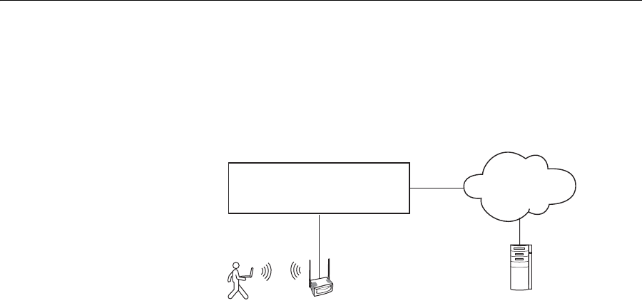
482 CHAPTER 21: CONFIGURING AAA FOR NETWORK USERS
Configuring AAA
for Users of
Third-Party APs
A WX switch can provide network access for users associated with a
third-party AP that has authenticated the users with RADIUS. You can
connect a third-party AP to a WX switch and configure the WX to provide
authorization for clients who authenticate and access the network
through the AP. Figure 32 shows an example.
Figure 32 WX Switch Serving as RADIUS Proxy
Authentication
Process for Users of a
Third-Party AP
The authentication process for users of a third-party AP is as follows:
1MSS uses MAC authentication to authenticate the AP.
2The user contacts the AP and negotiates the authentication protocol to
be used.
3The AP, acting as a RADIUS client, sends a RADIUS access-request to the
WX. The access-request includes the SSID, the user’s MAC address, and
the username.
4For 802.1X users, the AP uses 802.1X to authenticate the user, using the
WX as its RADIUS server. The WX proxies RADIUS requests from the AP to
a real RADIUS server, depending on the authentication method specified
in the proxy authentication rule for the user.
For non-802.1X users, the AP does not use 802.1X. The WX sends a
RADIUS query for the special username web-portal-ssid or
last-resort-ssid, where ssid is the SSID name. The fallthru authentication
type (web-portal or last-resort) specified for the wired authentication
port connected to the AP determines which username is used.
WX Switch
Wired Layer 2
connection
RADIUS server
Layer 2
or Layer 3
Configuring AAA for Users of Third-Party APs 483
For any users of an AP that sends SSID traffic to the WX on an untagged
VLAN, the WX does not use 802.1X. The WX sends a RADIUS query for
the special username web-portal-wired or last-resort-wired,
depending on the fallthru authentication type specified for the wired
authentication port.
5After successful RADIUS authentication of the user (or special username,
for non-802.1X users), MSS assigns authorization attributes to the user
from the RADIUS server’s access-accept response.
6When the user’s session ends, the third-party AP sends a RADIUS
stop-accounting record to the WX. The WX then removes the session.
Requirements Third-Party AP Requirements
The third-party AP must be connected to the WX switch through a
wired Layer 2 link. MSS cannot provide data services if the AP and WX
are in different Layer 3 subnets.
The AP must be configured as the WX’s RADIUS client.
The AP must be configured so that all traffic for a given SSID is
mapped to the same 802.1Q tagged VLAN. If the AP has multiple
SSIDs, each SSID must use a different tag value.
The AP must be configured to send the following information in a
RADIUS access-request, for each user who wants to connect to the
WLAN through the WX switch:
SSID requested by the user. The SSID can be attached to the end of
the called-station-id (per Congdon), or can be in a VSA (for
example, cisco-vsa:ssid=r12-cisco-1).
Calling-station-id that includes the user’s MAC address. The MAC
address can be in any of the following formats:
— Separated by colons (for example, AA:BB:CC:DD:EE:FF)
— Separated by dashes (for example, AA-BB-CC-DD-EE-FF)
— Separated by dots (for example, AABB.CCDD.EEFF)
Username
The AP must be configured to send a RADIUS stop-accounting record
when a user’s session ends.

484 CHAPTER 21: CONFIGURING AAA FOR NETWORK USERS
WX Switch Requirements
The WX port connected to the third-party AP must be configured as a
wired authentication port. If SSID traffic from the AP is tagged, the
same VLAN tag value must be used on the wired authentication port.
A MAC authentication rule must be configured to authenticate the
AP.
The WX must be configured as a RADIUS proxy for the AP. The WX is
a RADIUS server to the AP but remains a RADIUS client to the real
RADIUS servers.
The WX system IP address must be the same as the IP address configured
on the VLAN that contains the proxy port.
An authentication proxy rule must be configured for the AP’s users.
The rule matches based on SSID and username, and selects the
authentication method (a RADIUS server group) for proxying.
RADIUS Server Requirements
For 802.1X users, the usernames and passwords must be configured
on the RADIUS server.
For non-802.1X users of a tagged SSID, the special username
web-portal-ssid or last-resort-ssid must be configured, where ssid
is the SSID name. The fallthru authentication type (web-portal or
last-resort) specified for the wired authentication port connected to
the AP determines which username you need to configure.
For any users of an untagged SSID, the special username
web-portal-wired or last-resort-wired must be configured,
depending on the fallthru authentication type specified for the wired
authentication port.
Configuring
Authentication for
802.1X Users of a
Third-Party AP with
Tagged SSIDs
To configure MSS to authenticate 802.1X users of a third-party AP, use
the commands below to do the following:
Configure the port connected to the AP as a wired authentication
port. Use the following command:
set port type wired-auth port-list [tag tag-list]
[max-sessions num]
[auth-fall-thru {last-resort |none |web-portal}]
Configuring AAA for Users of Third-Party APs 485
Configure a MAC authentication rule for the AP. Use the following
command:
set authentication mac wired mac-addr-glob method1
Configure the WX port connected to the AP as a RADIUS proxy for the
SSID supported by the AP. If SSID traffic from the AP is tagged, assign
the same tag value to the WX port. Use the following command:
set radius proxy port port-list [tag tag-value] ssid
ssid-name
Add a RADIUS proxy entry for the AP. The proxy entry specifies the IP
address of the AP and the UDP ports on which the WX switch listens
for RADIUS access-requests and stop-accounting records from the AP.
Use the following command:
set radius proxy client address ip-address [port
udp-port-number] [acct-port acct-udp-port-number] key string
Configure a proxy authentication rule for the AP’s users. Use the
following command:
set authentication proxy ssid ssid-name user-glob
radius-server-group
For the port-list of the set port type wired-auth and set radius proxy
port commands, specify the WX port(s) connected to the third-party AP.
For the ip-address of the set radius proxy client address command,
specify the IP address of the RADIUS client (the third-party AP). For the
udp-port-number, specify the UDP port on which the WX switch will
listen for RADIUS access-requests. The default is UDP port 1812. For the
acct-udp-port-number, specify the UDP port on which the WX switch will
listen for RADIUS stop-accounting records. The default is UDP port 1813.
The following command configures WX ports 3 and 4 as wired
authentication ports, and assigns tag value 104 to the ports:
WX4400# set port type wired-auth 3-4 tag 104
success: change accepted.
You can specify multiple tag values. Specify the tag value for each SSID
you plan to support.

486 CHAPTER 21: CONFIGURING AAA FOR NETWORK USERS
The following command configures a MAC authentication rule that
matches on the third-party AP’s MAC address. Because the AP is
connected to the WX switch on a wired authentication port, the wired
option is used.
WX4400# set authentication mac wired aa:bb:cc:01:01:01
srvrgrp1
success: change accepted.
The following command maps SSID mycorp to packets received on port 3
or 4, using 802.1Q tag value 104:
WX4400# set radius proxy port 3-4 tag 104 ssid mycorp
success: change accepted.
Enter a separate command for each SSID, and its tag value, you want the
WX to support.
The following command configures a RADIUS proxy entry for a
third-party AP RADIUS client at 10.20.20.9, sending RADIUS traffic to the
default UDP ports 1812 and 1813 on the WX:
WX2200# set radius proxy client address 10.20.20.9 key
radkey1
success: change accepted.
The IP address is the AP’s IP address. The key is the shared secret
configured on the RADIUS servers. MSS uses the shared secret to
authenticate and encrypt RADIUS communication.
The following command configures a proxy authentication rule that
matches on all usernames associated with SSID mycorp. MSS uses
RADIUS server group srvrgrp1 to proxy RADIUS requests and hence to
authenticate and authorize the users.
WX4400# set authentication proxy ssid mycorp ** srvrgrp1
MSS also uses the server group you specify with this command for
accounting.
To verify the changes, use the display config area aaa command.

Assigning Authorization Attributes 487
Configuring
Authentication for
Non-802.1X Users of
a Third-Party AP with
Tagged SSIDs
To configure MSS to authenticate non-802.1X users of a third-party AP,
use the same commands as those required for 802.1X users. Additionally,
when configuring the wired authentication port, use the auth-fall-thru
option to change the fallthru authentication type to last-resort or
web-portal.
On the RADIUS server, configure username web-portal-ssid or
last-resort-ssid, depending on the fallthru authentication type you
specify for the wired authentication port.
Configuring Access
for Any Users of a
Non-Tagged SSID
If SSID traffic from the third-party AP is untagged, use the same
configuration commands as the ones required for 802.1X users, except
the set radius proxy port command. This command is not required and
is not applicable to untagged SSID traffic. In addition, when configuring
the wired authentication port, use the auth-fall-thru option to change
the fallthru authentication type to last-resort or web-portal.
On the RADIUS server, configure username web-portal-wired or
last-resort-wired, depending on the fallthru authentication type
specified for the wired authentication port.
Assigning
Authorization
Attributes
Authorization attributes can be assigned to users in the local database on
remote servers, or in the service profile of the SSID the user logs into. The
attributes, which include access control list (ACL) filters, VLAN
membership, encryption type, session time-out period, and other session
characteristics, let you control how and when users access the network.
When a user or group is authenticated, the local database, RADIUS
server, or service profile passes the authorization attributes to MSS to
characterize the user’s session.
If attributes are configured for a user and also for the group the user is in,
the attributes assigned to the individual user take precedence for that
user. For example, if the start-date attribute configured for a user is
sooner than the start-date configured for the user group the user is in,
the user’s network access can begin as soon as the user start-date. The
user does not need to wait for the user group’s start date.
The VLAN attribute is required. MSS can authorize a user to access the
network only if the VLAN to place the user on is specified.

488 CHAPTER 21: CONFIGURING AAA FOR NETWORK USERS
Table 43 lists the authorization attributes supported by MSS. (For brief
descriptions of all the RADIUS attributes and 3Com vendor-specific
attributes supported by MSS, as well as the vendor ID and types for 3Com
VSAs configured on a RADIUS server “Supported RADIUS Attributes” on
page 651.)
Table 43 Authentication Attributes for Local Users
Attribute Description Valid Value(s)
acct-interim-inte
rval
Interval in seconds
between accounting
updates, if start-stop
accounting mode is
enabled.
Number between 180 and 3600
seconds, or 0 to disable periodic
accounting updates.
Notes:
The WX switch ignores the
acct-interim-interval value and
issues a log message if the value is
below 60 seconds.
If both a RADIUS server and the
WX switch supply a value for the
acct-interim-interval attribute,
then the value from the WX switch
takes precedence.
encryption-type Type of encryption
required for access by
the client. Clients who
attempt to use an
unauthorized
encryption method are
rejected.
One of the following numbers that
identifies an encryption algorithm:
1 — AES_CCM (Advanced
Encryption Standard using Counter
with CBC-MAC)
2 — Reserved
4 — TKIP (Temporal Key Integrity
Protocol)
8 — WEP_104 (the default)
(Wired-Equivalent Privacy protocol
using 104 bits of key strength)
16 — WEP_40 (Wired-Equivalent
Privacy protocol using 40 bits of
key strength)
32 — NONE (no encryption)
64 — Static WEP
In addition to these values, you can
specify a sum of them for a
combination of allowed encryption
types. For example, to specify
WEP_104 and WEP_40, use 24.

Assigning Authorization Attributes 489
end-date Date and time after
which the user is no
longer allowed to be
on the network.
Date and time, in the following
format:
YY/MM/DD-HH:MM
You can use end-date alone or with
start-date. You also can use
start-date, end-date, or both in
conjunction with time-of-day.
filter-id
(network access
mode only)
Security access control
list (ACL), to permit or
deny traffic received
(input) or sent (output)
by the WX switch.
(For more information
about security ACLs,
see Chapter 19,
“Configuring and
Managing Security
ACLs,” on page 377.)
Name of an existing security ACL, up
to 32 alphanumeric characters, with
no tabs or spaces.
Use acl-name.in to filter traffic that
enters the switch from users via a
MAP access port or wired
authentication port, or from the
network via a network port.
Use acl-name.out to filter traffic
sent from the switch to users via a
MAP access port or wired
authentication port, or from the
network via a network port.
If the Filter-Id value returned through
the authentication and authorization
process does not match the name of a
committed security ACL in the WX, the
user fails authorization and is unable
to authenticate.
idle-timeout This option is not implemented in the current MSS version.
mobility-profile
(network access
mode only)
Mobility Profile
attribute for the user.
(For more information,
see “Configuring a
Mobility Profile” on
page 510.)
Name of an existing Mobility Profile,
which can be up to 32 alphanumeric
characters, with no tabs or spaces.
Note: If the Mobility Profile feature is
enabled, and a user is assigned the
name of a Mobility Profile that does
not exist on the WX switch, the user is
denied access.
Table 43 Authentication Attributes for Local Users (continued)
Attribute Description Valid Value(s)

490 CHAPTER 21: CONFIGURING AAA FOR NETWORK USERS
service-type Type of access the user
is requesting. One of the following numbers:
2—Framed; for network user access
6—Administrative; for administrative
access to the WX switch, with
authorization to access the enabled
(configuration) mode. The user must
enter the enable command to access
the enabled mode.
7—NAS-Prompt; for administrative
access to the nonenabled mode only.
In this mode, the enable command is
not available and the user cannot log
in to the enabled mode.
For administrative sessions, the WX
switch will send 7 (NAS-Prompt) unless
the service-type attribute has been
configured for the user.
The RADIUS server can reply with one
of the values listed above.
If the service-type is not set on the
RADIUS server, administrative users
receive NAS-Prompt access, and
network users receive Framed access.
Note: MSS will quietly accept Callback
Framed, but you cannot select this
access type in MSS.
session-timeout
(network access
mode only)
Maximum number of
seconds for the user’s
session.
Number between 0 and
4,294,967,296 seconds
(approximately 136.2 years).
ssid
(network access
mode only)
SSID the user is
allowed to access after
authentication.
Name of the SSID you want the user to
use. The SSID must be configured in a
service profile, and the service profile
must be used by a radio profile
assigned to 3Com radios in the
Mobility Domain.
Table 43 Authentication Attributes for Local Users (continued)
Attribute Description Valid Value(s)

Assigning Authorization Attributes 491
start-date Date and time at which
the user becomes eligible
to access the network.
MSS does not
authenticate the user
unless the attempt to
access the network occurs
at or after the specified
date and time, but before
the end-date (if specified).
Date and time, in the following
format:
YY/MM/DD-HH:MM
You can use start-date alone or with
end-date. You also can use
start-date, end-date, or both in
conjunction with time-of-day.
time-of-day
(network access
mode only)
Day(s) and time(s)
during which the user
is permitted to log into
the network.
After authorization,
the user’s session can
last until either the
Time-Of-Day range or
the Session-Timeout
duration (if set) expires,
whichever is shorter.
One of the following:
never — Access is always denied.
any — Access is always allowed.
al — Access is always allowed.
One or more ranges of values that
consist of one of the following day
designations (required), and a time
range in hhmm-hhmm 4-digit
24-hour format (optional):
mo — Monday
tu — Tuesday
we — Wednesday
th — Thursday
fr — Friday
sa — Saturday
su — Sunday
wk — Any day between Monday
and Friday
Separate values or a series of ranges
(except time ranges) with commas (,)
or a vertical bar (|). Do not use spaces.
The maximum number of characters is 253.
For example, to allow access only on
Tuesdays and Thursdays between
10 a.m. and 4 p.m., specify the
following:
time-of-day tu1000-1600,th1000-1600
To allow access only on weekdays
between 9 a.m and 5 p.m., and on
Saturdays from 10 p.m. until 2 a.m.,
specify the following:
time-of-day wk0900-1700,sa2200-0200
Note: You can use time-of-day in
conjunction with start-date,
end-date, or both.
Table 43 Authentication Attributes for Local Users (continued)
Attribute Description Valid Value(s)

492 CHAPTER 21: CONFIGURING AAA FOR NETWORK USERS
Assigning Attributes
to Users and Groups
You can assign authorization attributes to individual users or groups of
users. Use any of the following commands to assign an attribute to a user
or group in the local WX database and specify its value:
set user username attr attribute-name value
set usergroup group-name attr attribute-name value
set mac-user mac-addr attr attribute-name value
set mac-usergroup group-name attr attribute-name value
If attributes are configured for a user and also for the group the user is in,
the attributes assigned to the individual user take precedence for that
user. For example, if the start-date attribute configured for a user is
sooner than the start-date configured for the user group the user is in,
the user’s network access can begin as soon as the user start-date. The
user does not need to wait for the user group’s start date.
url
(network access
mode only)
URL to which the user
is redirected after
successful WebAAA.
Web URL, in standard format. For
example:
http://www.example.com
Note: You must include the http://
portion.
You can dynamically include any of
the variables in the URL string:
$u—Username
$v—VLAN
$s—SSID
$p—Service profile name
To use the literal character $ or ?, use
the following:
$$
$q
vlan-name
(network access
mode only)
Virtual LAN (VLAN)
assignment.
Note: On some
RADIUS servers, you
might need to use the
standard RADIUS
attribute
Tunnel-Pvt-Group-ID,
instead of VLAN-Name.
Name of a VLAN that you want the
user to use. The VLAN must be
configured on a WX switch within the
Mobility Domain to which this WX
switch belongs.
Table 43 Authentication Attributes for Local Users (continued)
Attribute Description Valid Value(s)
Assigning Authorization Attributes 493
To change the value of an authorization attribute, reenter the command
with the new value.
To assign an authorization attribute to a user’s configuration on a
RADIUS server, see the documentation for your RADIUS server.
Assigning SSID
Default Attributes to
a Service Profile
You can configure a service profile with a set of default AAA
authorization attributes that are used when the normal AAA process or a
location policy does not provide them. These authorization attributes are
applied by default to users accessing the SSID managed by the service
profile.
Use the following command to assign an authorization attribute to a
service profile and specify its value:
set service-profile name attr attribute-name value
By default, a service profile contains no SSID default authorization
attributes. When specified, attributes in a service profile are applied in
addition to any attributes supplied for the user by the RADIUS server or
the local database. When the same attribute is specified both as an SSID
default attribute and through AAA, then the attribute supplied by the
RADIUS server or the local database takes precedence over the SSID
default attribute. If a location policy is configured, the location policy
takes precedence over both AAA and SSID default attributes. The SSID
default attributes serve as a fallback when neither the AAA process, nor a
location policy, provides them.
For example, a service profile might be configured with the service-type
attribute set to 2. If a user accessing the SSID is authenticated by a
RADIUS server, and the RADIUS server returns the vlan-name attribute
set to orange, then that user will have a total of two attributes set:
service-type and vlan-name.
If the service profile is configured with the vlan-name attribute set to
blue, and the RADIUS server returns the vlan-name attribute set to
orange, then the attribute from the RADIUS server takes precedence; the
user is placed in the orange VLAN.
You can display the attributes for each connected user and whether they
are set through AAA or through SSID defaults by entering the display
sessions network verbose command. You can display the configured
SSID defaults by entering the display service-profile command.
494 CHAPTER 21: CONFIGURING AAA FOR NETWORK USERS
All of the authorization attributes listed in Table 40 on page 448 can be
specified in a service profile except ssid.
Assigning a Security
ACL to a User or a
Group
Once a security access control list (ACL) is defined and committed, it can
be applied dynamically and automatically to users and user groups
through the 802.1X authentication and authorization process. When you
assign a Filter-Id attribute to a user or group, the security ACL name value
is entered as an authorization attribute into the user or group record in
the local WX database or RADIUS server.
If the Filter-Id value returned through the authentication and
authorization process does not match the name of a committed security
ACL in the WX, the user fails authorization and cannot be connected.
(For details about security ACLs, see Chapter 19, “Configuring and
Managing Security ACLs,” on page 377.)
Assigning a Security ACL Locally
To use the local WX database to restrict a user, a MAC user, or a group of
users or MAC users to the permissions stored within a committed security
ACL, use the commands shown in Table 44.
Table 44 Commands for Assigning a Security ACL Locally
Security ACL Target Commands
User authenticated
by a password set user username attr filter-id acl-name.in
set user username attr filter-id acl-name.out
Group of users
authenticated by a
password
set usergroup groupname attr filter-id acl-name.in
set usergroup groupname attr filter-id acl-name.out
User authenticated
by a MAC address set mac-user username attr filter-id acl-name.in
set mac-user username attr filter-id acl-name.out
Group of users
authenticated by a
MAC address
set mac-usergroup groupname attr filter-id acl-name.in
set mac-usergroup groupname attr filter-id acl-name.out
Assigning Authorization Attributes 495
You can set filters for incoming and outgoing packets:
Use acl-name.in to filter traffic that enters the WX switch from users
via a MAP access port or wired authentication port, or from the
network via a network port.
Use acl-name.out to filter traffic sent from the WX switch to users via
a MAP access port or wired authentication port, or from the network
via a network port.
For example, the following command applies security ACL acl-101 to
packets coming into the WX from user Jose:
WX1200# set user Jose attr filter-id acl-101.in
success: change accepted.
The following command applies the incoming filters of acl-101 to the
users who belong to the group eastcoasters:
WX1200# set usergroup eastcoasters attr filter-id acl-101.in
success: change accepted.
Assigning a Security ACL on a RADIUS Server
To assign a security ACL name as the Filter-Id authorization attribute of a
user or group record on a RADIUS server, see the documentation for your
RADIUS server.
Clearing a Security
ACL from a User or
Group
To clear a security ACL from the profile of a user, MAC user, or group of
users or MAC users in the local WX database, use the following
commands:
clear user username attr filter-id
clear usergroup groupname attr filter-id
clear mac-user username attr filter-id
clear mac-usergroup groupname attr filter-id
If you have assigned both an incoming and an outgoing filter to a user or
group, enter the appropriate command twice to delete both security
ACLs. Verify the deletions by entering the display aaa command and
checking the output.
To delete a security ACL from a user’s configuration on a RADIUS server,
see the documentation for your RADIUS server.

496 CHAPTER 21: CONFIGURING AAA FOR NETWORK USERS
Assigning Encryption
Types to Wireless
Users
When a user turns on a wireless laptop or PDA, the device attempts to
find an access point and form an association with it. Because MAPs
support the encryption of wireless traffic, clients can choose an
encryption type to use. You can configure MAPs to use the encryption
algorithms supported by the Wi-Fi Protected Access (WPA) security
enhancement to the IEEE 802.11 wireless standard. (For details, see
Chapter 13, “Configuring User Encryption,” on page 281.)
If you have configured MAPs to use specific encryption algorithms, you
can enforce the type of encryption a user or group must have to access
the network. When you assign the Encryption-Type attribute to a user or
group, the encryption type or types are entered as an authorization
attribute into the user or group record in the local WX database or on the
RADIUS server. Encryption-Type is a 3Com vendor-specific attribute
(VSA).
Clients who attempt to use an unauthorized encryption method are
rejected.
Assigning and Clearing Encryption Types Locally
To restrict wireless uses or groups with user profiles in the local WX
database to particular encryption algorithms for accessing the network,
use one of the following commands:
set user username attr encryption-type value
set usergroup groupname attr encryption-type value
set mac-user username attr encryption-type value
set mac-usergroup groupname attr encryption-type value
MSS supports the values for Encryption-Type shown in Table 45. The
values are listed from most secure to least secure. (For user encryption
details, see Chapter 13, “Configuring User Encryption,” on page 281.)
Table 45 Encryption Type Values and Associated Algorithms
Encryption-Type
Value
Encryption Algorithm
Assigned
1Advanced Encryption Standard using Counter with Cipher
Block Chaining Message Authentication Code (CBC-MAC) —
or AES_CCM.
2Reserved.
4Temporal Key Integrity Protocol (TKIP).

Assigning Authorization Attributes 497
For example, the following command restricts the MAC user group
mac-fans to access the network by using only TKIP:
WX1200# set mac-usergroup mac-fans attr encryption-type 4
success: change accepted.
You can also specify a combination of allowed encryption types by
summing the values. For example, the following command allows
mac-fans to associate using either TKIP or WEP_104:
WX1200# set mac-usergroup mac-fans attr encryption-type 12
success: change accepted.
To clear an encryption type from the profile of a use or group of users in
the local WX database, use one of the following commands:
clear user username attr encryption-type
clear usergroup groupname attr encryption-type
clear mac-user username attr encryption-type
clear mac-usergroup groupname attr encryption-type
Assigning and Clearing Encryption Types on a RADIUS Server
To assign or delete an encryption algorithm as the Encryption-Type
authorization attribute in a user or group record on a RADIUS server, see
the documentation for your RADIUS server.
8Wired-Equivalent Privacy protocol using 104 bits of key
strength (WEP_104). This is the default.
16 Wired-Equivalent Privacy protocol using 40 bits of key strength
(WEP_40).
32 No encryption.
64 Static WEP
Table 45 Encryption Type Values and Associated Algorithms (continued)
Encryption-Type
Value
Encryption Algorithm
Assigned

498 CHAPTER 21: CONFIGURING AAA FOR NETWORK USERS
Keeping Users on the
Same VLAN Even
After Roaming
In some cases, a user can be assigned to a different VLAN after roaming
to another WX switch.
Table 46 lists the ways a VLAN can be assigned to a user after roaming
from one WX to another.
Yes in the table means the VLAN is set on the roamed-to WX, by the
mechanism indicated by the column header. No means the VLAN is not
set. Yes or No means the mechanism does not affect the outcome, due to
another mechanism that is set.
The VLAN Assigned By column indicates the mechanism that is used by
the roamed-to switch to assign the VLAN, based on the various ways the
VLAN is set on that switch.
Location Policy means the VLAN is assigned by a location policy on the
roamed-to switch. (The VLAN is assigned by the vlan vlan-id option of
the set location policy permit command.)
AAA means the Vlan-name attribute is set on for the user or the user’s
group, in the roamed-to switch’s local database or on a RADIUS server
used by the roamed-to switch to authenticate the user. (The VLAN is
assigned by the vlan-name vlan-id option of the set user attr, set
usergroup attr, set mac-user, or set mac-usergroup command.)
keep-initial-vlan means that the VLAN is not reassigned. Instead, the
VLAN assigned on the switch where the user first accesses the
network is retained. (The keep-initial-vlan option is enabled by the
set service-profile name keep-initial-vlan enable command,
entered on the roamed-to switch. The name is the name of the service
profile for the SSID the user is associated with.)
Table 46 VLAN Assignment After Roaming from One WX to Another
Location
Policy AAA keep-initial-vlan SSID VLAN Assigned By...
Yes Yes or No Yes or No Yes or No location policy
No Yes Yes or No Yes or No AAA
No No Yes Yes or No keep-initial-vlan
No No No Yes SSID
No No No No Not set—authentication
error

Overriding or Adding Attributes Locally with a Location Policy 499
SSID means the VLAN is set on the roamed-to switch, in the service
profile for the SSID the user is associated with. (The Vlan-name
attribute is set by the set service-profile name attr vlan-name
vlan-id command, entered on the roamed-to switch. The name is the
name of the service profile for the SSID the user is associated with.)
As shown in Table 46, even when keep-initial-vlan is set, a user’s
VLAN can be reassigned by AAA or a location policy.
The keep-initial-vlan option does not apply to Web-Portal clients. Instead,
VLAN assignment for roaming Web-Portal clients automatically works the
same way as when keep-initial-vlan is enabled. The VLAN initially
assigned to a Web-Portal user is not changed except by a location policy,
AAA, or SSID default setting on the roamed-to switch.
To enable keep-initial-vlan, use the following command:
set service-profile name keep-initial-vlan {enable | disable}
Enter this command on the switch that will be roamed to by users.
The following command enables the keep-initial-vlan option on service
profile sp3:
WX1200# set service-profile sp3 keep-initial-vlan enable
success: change accepted.
Overriding or
Adding Attributes
Locally with a
Location Policy
During the login process, the AAA authorization process is started immediately
after clients are authenticated to use the WX switch. During authorization,
MSS assigns the user to a VLAN and applies optional user attributes, such as a
session timeout value and one or more security ACL filters.
A location policy is a set of rules that enables you to locally set or change
authorization attributes for a user after the user is authorized by AAA,
without making changes to the AAA server. For example, you might want
to enforce VLAN membership and security ACL policies on a particular
WX based on a client’s organization or physical location, or assign a
VLAN to users who have no AAA assignment. For these situations, you
can configure the location policy on the switch.
You can use a location policy to locally set or change the Filter-Id and
VLAN-Name authorization attributes obtained from AAA.
500 CHAPTER 21: CONFIGURING AAA FOR NETWORK USERS
About the Location
Policy
Each WX switch can have one location policy. The location policy consists of
a set of rules. Each rule contains conditions, and an action to perform if all
conditions in the rule match. The location policy can contain up to 50 rules.
The action can be one of the following:
Deny access to the network
Permit access, but set or change the user’s VLAN assignment, inbound
ACL, outbound ACL, or any combination of these attributes
The conditions can be one or more of the following:
AAA-assigned VLAN
Username
MAP access port, Distributed MAP number, or wired authentication
port through which the user accessed the network
SSID name with which the user is associated
Conditions within a rule are ANDed. All conditions in the rule must match
in order for MSS to take the specified action. If the location policy
contains multiple rules, MSS compares the user information to the rules
one at a time, in the order the rules appear in the switch’s configuration
file, beginning with the rule at the top of the list. MSS continues
comparing until a user matches all conditions in a rule or until there are
no more rules.
Any authorization attributes not changed by the location policy remain
active.
How the Location
Policy Differs from a
Security ACL
Although structurally similar, the location policy and security ACLs have
different functions. The location policy on a WX switch can be used to
locally redirect a user to a different VLAN or locally control the traffic to
and from a user.
In contrast, security ACLs are packet filters applied to the user throughout
a Mobility Domain. (For more information, see Chapter 19, “Configuring
and Managing Security ACLs,” on page 377.)
You can use the location policy to locally apply a security ACL to a user.

Overriding or Adding Attributes Locally with a Location Policy 501
Setting the Location
Policy
To enable the location policy function on a WX switch, you must create at
least one location policy rule with one of the following commands:
set location policy deny if
{ssid operator ssid-name | vlan operator vlan-glob | user
operator user-glob | port port-list | dap dap-num} [before
rule-number | modify rule-number]
set location policy permit
{vlan vlan-name | inacl inacl-name | outacl outacl-name}
if {ssid operator ssid-name | vlan operator vlan-glob | user
operator user-glob | port port-list | dap dap-num}
[before rule-number | modify rule-number]
Asterisks (wildcards) are not supported in SSID names. You must specify
the complete SSID name.
You must specify whether to permit or deny access, and you must
identify a VLAN, username, or access port to match. Use one of the
following operators to specify how the rule must match the VLAN or
username:
eq — Applies the location policy rule to all users assigned VLAN
names matching vlan-glob or having usernames that match user-glob.
(Like a user glob, a VLAN glob is a way to group VLANs for use in this
command. For more information, see “VLAN Globs” on page 31.)
neq — Applies the location policy rule to all users assigned VLAN
names not matching vlan-glob or having usernames that do not
match user-glob.
For example, the following command denies network access to all users
matching *.theirfirm.com, causing them to fail authorization:
WX1200# set location policy deny if user eq *.theirfirm.com
The following command authorizes access to the guest_1 VLAN for all
users who do not match *.ourfirm.com:
WX1200# set location policy permit vlan guest_1 if user neq
*.ourfirm.com
502 CHAPTER 21: CONFIGURING AAA FOR NETWORK USERS
The following command places all users who are authorized for SSID
tempvendor_a into VLAN kiosk_1:
WX1200# set location policy permit vlan kiosk_1 if ssid eq
tempvendor_a
success: change accepted.
Applying Security ACLs in a Location Policy Rule
When reassigning security ACL filters, specify whether the filter is an
input filter or an output filter, as follows:
Input filter — Use inacl inacl-name to filter traffic that enters the
switch from users via a MAP access port or wired authentication port,
or from the network via a network port.
Output filter — Use outacl outacl-name to filter traffic sent from the
switch to users via a MAP access port or wired authentication port, or
from the network via a network port.
For example, the following command authorizes users at
*.ny.ourfirm.com to access the bld4.tac VLAN, and applies the security
ACL tac_24 to the traffic they receive:
WX1200# set location policy permit vlan bld4.tac outacl
tac_24 if user eq *.ny.ourfirm.com
The following command authorizes access to users on VLANs with names
matching bld4.* and applies security ACLs svcs_2 to the traffic they send
and svcs_3 to the traffic they receive:
WX1200# set location policy permit inacl svcs_2
outacl svcs_3 if vlan eq bldg4.*
You can optionally add the suffixes .in and .out to inacl-name and
outacl-name for consistency with their usage in entries stored in the local
WX database.
Displaying and Positioning Location Policy Rules
The order of location policy rules is significant. MSS checks a location
policy rule that is higher in the list before those lower in the list. Rules are
listed in the order in which you create them, unless you move them.
To position location policy rules within the location policy, use before
rule-number and modify rule-number in the set location policy
command, or use the clear location policy rule-number command.
Overriding or Adding Attributes Locally with a Location Policy 503
For example, suppose you have configured the following location policy
rules:
WX1200 display location policy
Id Clauses
----------------------------------------------------------------
1) deny if user eq *.theirfirm.com
2) permit vlan guest_1 if vlan neq *.ourfirm.com
3) permit vlan bld4.tac inacl tac_24.in if user eq *.ny.ourfirm.com
4) permit inacl svcs_2.in outacl svcs_3.out if vlan eq bldg4.*
To move the first rule to the end of the list and display the results, type the
following commands:
WX1200 clear location policy 1
success: clause 1 is removed.
WX1200 set location policy deny if user eq
*.theirfirm.com
WX1200 display location policy
Id Clauses
----------------------------------------------------------------
1) permit vlan guest_1 if vlan neq *.ourfirm.com
2) permit vlan bld4.tac inacl tac_24.in if user eq *.ny.ourfirm.com
3) permit inacl svcs_2.in outacl svcs_3.out if vlan eq bldg4.*
4) deny if user eq *.theirfirm.com
Clearing Location
Policy Rules and
Disabling the
Location Policy
To delete a location policy rule, use the following command:
clear location policy rule-number
Type display location policy to display the numbers of configured
location policy rules. To disable the location policy on a WX switch, delete
all the location policy rules.

504 CHAPTER 21: CONFIGURING AAA FOR NETWORK USERS
Configuring
Accounting for
Wireless Network
Users
Accounting records come in three types: start-stop, stop-only, and
update for network users. The records provide information about
network resource usage.
To set accounting, type the following command:
set accounting {admin | console | dot1x |
mac | web | last-resort} {ssid ssid-name | wired}
{user-glob | mac-addr-glob} {start-stop |stop-only}
method1 [method2] [method3] [method4]
For example, to store start-stop accounting records at example.com for
802.1X users of SSID mycorp in the local database, type the following
command:
WX1200# set accounting dot1x ssid mycorp *@example.com
start-stop local
success: change accepted.
The accounting records can contain the session information shown in
Table 47.
Table 47 Session Information Shown in Accounting Records
Start Records Update and Stop Records
Session date and time Session date and time
Location of authentication (if any):
RADIUS server (1) or local database (2) Location of authentication (if any):
RADIUS server (1) or local database (2)
ID for related sessions ID for related sessions
Username Username
Session duration Session duration
Timestamp Timestamp
VLAN name VLAN name
Client’s MAC address Client’s MAC address
MAP port number and radio number MAP port number and radio number
MAP’s MAC address MAP’s MAC address
Number of octets received by the WX
switch
Number of octets sent by the switch
Number of packets received by the switch
Number of packets sent by the switch
Configuring Accounting for Wireless Network Users 505
(For details about display accounting statistics output, see the Wireless
LAN Switch and Controller Command Reference. For information about
accounting update records, see “Viewing Roaming Accounting Records”
on page 505. To configure accounting on a RADIUS server, see the
documentation for your RADIUS server.)
Viewing Local
Accounting Records
To view local accounting records, type the following command:
WX1200# display accounting statistics
Viewing Roaming
Accounting Records
During roaming, accounting is treated as a continuation of an existing
session, rather than a new session. The following sample output shows a
wireless user roaming from one WX switch to another WX switch.
From the accounting records, you can determine the user’s activities by
viewing the Acct-Status-Type, which varies from START to UPDATE to
STOP, and the Called-Station-Id, which is the MAC address of the MAP
through which the wireless user accessed the network. The
Acct-Multi-Session-Id is guaranteed to be globally unique for the client.
By entering display accounting statistics commands on each WX
switch involved in the roaming, you can determine the user’s movements
between WX switches when accounting is configured locally.
The user started on WX1200-0013:
WX1200-0013# display accounting statistics
May 21 17:01:32
Acct-Status-Type=START
Acct-Authentic=2
User-Name=Administrator@example.com
Acct-Multi-Session-Id=SESSION-4-1106424789
Event-Timestamp=1053536492
Vlan-Name=default
Calling-Station-Id=00-06-25-09-39-5D
Nas-Port-Id=1/1
Called-Station-Id=00-0B-0E-76-56-A8
The user roamed to WX1200-0017.
WX1200-0017# display accounting statistics
May 21 17:05:00
Acct-Status-Type=UPDATE
Acct-Authentic=2
Acct-Multi-Session-Id=SESSION-4-1106424789
506 CHAPTER 21: CONFIGURING AAA FOR NETWORK USERS
User-Name=Administrator@example.com
Acct-Session-Time=209
Acct-Output-Octets=1280
Acct-Input-Octets=1920
Acct-Output-Packets=10
Acct-Input-Packets=15
Event-Timestamp=1053536700
Vlan-Name=default
Calling-Station-Id=00-06-25-09-39-5D
Nas-Port-Id=2/1
Called-Station-Id=00-0B-0E-76-56-A0
The user terminated the session on WX1200-0017:
WX1200-0017# display accounting statistics
May 21 17:07:32
Acct-Status-Type=STOP
Acct-Authentic=2
Acct-Multi-Session-Id=SESSION-4-1106424789
User-Name=Administrator@example.com
Acct-Session-Time=361
Event-Timestamp=1053536852
Acct-Output-Octets=2560
Acct-Input-Octets=5760
Acct-Output-Packets=20
Acct-Input-Packets=45
Vlan-Name=default
Calling-Station-Id=00-06-25-09-39-5D
Nas-Port-Id=2/1
Called-Station-Id=00-0B-0E-76-56-A0
If you configured accounting records to be sent to a RADIUS server, you
can view the records of user roaming at the RADIUS server. (For more
information on these attributes, see “Supported RADIUS Attributes” on
page 651.)
For information about requesting accounting records from the RADIUS
server, see the documentation for your RADIUS server.

Displaying the AAA Configuration 507
Displaying the AAA
Configuration
To view the results of the AAA commands you have set and verify their
order, type the display aaa command. The order in which the
commands appear in the output determines the order in which MSS
matches them to users.
(Sometimes the order might not be what you intended. See “Avoiding
AAA Problems in Configuration Order” on page 508.)
For example:
WX1200# display aaa
Default Values
authport=1812 acctport=1813 timeout=5 acct-timeout=5
retrans=3 deadtime=0 key=(null) author-pass=(null)
Radius Servers
Server Addr Ports T/o Tries Dead State
--------------------------------------------------------------------
rs-3 198.162.1.1 1821 1813 5 3 0 UP
rs-4 198.168.1.2 1821 1813 77 11 2 UP
rs-5 198.162.1.3 1821 1813 42 23 0 UP
Server groups
sg1: rs-3
sg2: rs-4
sg3: rs-5
Web Portal:
enabled
set authentication admin Jose sg3
set authentication console * none
set authentication mac ssid mycorp * local
set authentication dot1x ssid mycorp Geetha eap-tls
set authentication dot1x ssid mycorp * peap-mschapv2 sg1 sg2 sg3
set accounting dot1x Nin ssid mycorp stop-only sg2
set accounting admin Natasha start-stop local
user Nin
Password = 082c6c64060b (encrypted)
Filter-Id = acl-999.in
Filter-Id = acl-999.out
mac-user 01:02:03:04:05:06
usergroup eastcoasters
session-timeout = 99
For information about the fields in the output, see the Wireless LAN
Switch and Controller Command Reference.

508 CHAPTER 21: CONFIGURING AAA FOR NETWORK USERS
Avoiding AAA
Problems in
Configuration
Order
This section describes some common AAA configuration issues on the
WX switch and how to avoid them.
Using the Wildcard
“Any” as the SSID
Name in
Authentication Rules
You can configure an authentication rule to match on all SSID strings by
using the SSID string any in the rule. For example, the following rule
matches on all SSID strings requested by all users:
set authentication web ssid any ** sg1
MSS checks authentication rules in the order they appear in the
configuration file. As a result, if a rule with SSID any appears in the
configuration before a rule that matches on a specific SSID for the same
authentication type and userglob, the rule with any always matches first.
To ensure the authentication behavior that you expect, place the most
specific rules first and place rules with SSID any last. For example, to
ensure that users who request SSID corpa are authenticated using
RADIUS server group corpasrvr, place the following rule in the
configuration before the rule with SSID any:
set authentication web ssid corpa ** corpasrvr
Here is an example of a AAA configuration where the most-specific rules
for 802.1X and WebAAA are first and the rules with any are last:
WX1200# display aaa
...
set authentication dot1x ssid mycorp Geetha eap-tls
set authentication dot1x ssid mycorp * peap-mschapv2 sg1 sg2 sg3
set authentication dot1x ssid any ** peap-mschapv2 sg1 sg2 sg3
Using Authentication
and Accounting Rules
Together
When you use accounting commands with authentication commands
and identify users with user globs, MSS might not process the commands
in the order you entered them. As a result, user authentication or
accounting might not proceed as you intend, or valid users might fail
authentication and be shut out of the network.
You can prevent these problems by using duplicate user globs for
authentication and accounting and entering the commands in pairs.
Avoiding AAA Problems in Configuration Order 509
Configuration Producing an Incorrect Processing Order
For example, suppose you initially set up start-stop accounting as follows
for all 802.1X users via RADIUS server group 1:
WX1200# set accounting dot1x ssid mycorp * start-stop group1
success: change accepted.
You then set up PEAP-MS-CHAP-V2 authentication and authorization for all
users at EXAMPLE/ at server group 1. Finally, you set up PEAP-MS-CHAP-V2
authentication and authorization for all users in the local WX database, with
the intention that EXAMPLE users are to be processed first:
WX1200# set authentication dot1x ssid mycorp EXAMPLE/*
peap-mschapv2 group1
success: change accepted.
WX1200# set authentication dot1x ssid mycorp * peap-mschapv2
local
success: change accepted.
The following configuration order results. The authentication commands
are reversed, and MSS processes the authentication of all 802.1X users in
the local database and ignores the command for EXAMPLE/ users.
WX1200# display aaa
...
set accounting dot1x ssid mycorp * start-stop group1
set authentication dot1x ssid mycorp * peap-mschapv2 local
set authentication dot1x ssid mycorp EXAMPLE/* peap-mschapv2 group1
Configuration for a Correct Processing Order
To avoid processing errors for authentication and accounting commands
that include order-sensitive user globs, enter the commands for each user
glob in pairs.
For example, to set accounting and authorization for 802.1X users as you
intended in “Configuration Producing an Incorrect Processing Order” on
page 509, enter an accounting and authentication command for each
user glob in the order in which you want them processed:
WX1200# set accounting dot1x ssid mycorp EXAMPLE/* start-stop group1
success: change accepted.
WX1200# set authentication dot1x ssid mycorp EXAMPLE/* peap-mschapv2 group1
success: change accepted.
WX1200# set accounting dot1x ssid mycorp * start-stop group1
success: change accepted.
WX1200# set authentication dot1x ssid mycorp * peap-mschapv2 local
success: change accepted.

510 CHAPTER 21: CONFIGURING AAA FOR NETWORK USERS
The configuration order now shows that all 802.1X users are processed
as you intended:
WX1200# display aaa
...
set accounting dot1x ssid mycorp EXAMPLE/* start-stop group1
set authentication dot1x ssid mycorp EXAMPLE/* peap-mschapv2 group1
set accounting dot1x ssid mycorp * start-stop group1
set authentication dot1x ssid mycorp * peap-mschapv2 local
Configuring a
Mobility Profile
A Mobility Profile is a way of specifying, on a per-user basis, those users
who are allowed access to specified MAP access ports and wired
authentication ports on a WX switch. In this way, you can constrain the
areas to which a user can roam. You first create a Mobility Profile, assign
it to one or more users, and finally enable the Mobility Profile feature on
the WX.
CAUTION: When Mobility Profile attributes are enabled, a user is denied
access if assigned a Mobility-Profile attribute in the local WX switch
database or RADIUS server and no Mobility Profile of that name exists on
the WX switch.
Use the following command to create a Mobility Profile by giving it a
name and identifying the accessible port or ports:
set mobility-profile name name
{port {none | all | port-list}} | {dap {none | all |
dap-num}}
Specifying none prevents users assigned to the Mobility Profile from
accessing any MAP access ports, Distributed MAPs, or wired
authentication ports on the WX. Specifying all allows the users access to
all of the ports or Distributed MAPs.
Specifying an individual port or Distributed MAP number or a list limits
access to those ports or MAPs. For example, the following command
creates a Mobility Profile named roses-profile that allows access through
ports 2 through 4 and port 6:
WX1200# set mobility-profile name roses-profile port 2-4,6
success: change accepted.
Configuring a Mobility Profile 511
You can then assign this Mobility Profile to one or more users. For
example, to assign the Mobility Profile roses-profile to all users at
EXAMPLE\, type the following command:
WX1200# set user EXAMPLE\* attr mobility-profile roses-profile
success: change accepted.
(For a list of the commands for assigning attributes, see “Assigning
Attributes to Users and Groups” on page 492.)
During 802.1X authorization for clients at EXAMPLE\, MSS must search
for the Mobility Profile named roses-profile. If it is not found, the
authorization fails and clients with usernames like EXAMPLE\jose and
EXAMPLE\tamara are rejected.
If roses-profile is configured for EXAMPLE\ users on your WX, MSS checks
its port list. If, for example, the current port for EXAMPLE\jose’s
connection is on the list of allowed ports specified in roses-profile, the
connection is allowed to proceed. If the port is not in the list (for
example, EXAMPLE\jose is on port 5, which is not in the port list), the
authorization fails and client EXAMPLE\jose is rejected.
The Mobility Profile feature is disabled by default. You must enable
Mobility Profile attributes on the WX switch to use it. You can enable or
disable the feature for the whole WX only. If the Mobility Profile feature is
disabled, all Mobility Profile attributes are ignored.
To put Mobility Profile attributes into effect on a WX, type the following command:
WX1200# set mobility-profile mode enable
success: change accepted.
To display the name of each Mobility Profile and its ports, type the
following command:
WX1200# display mobility-profile
Mobility Profiles
Name Ports
=========================
roses-profile
AP 2
AP 3
AP 4
AP 6
To remove a Mobility Profile, type the following command:
clear mobility-profile name

512 CHAPTER 21: CONFIGURING AAA FOR NETWORK USERS
Network User
Configuration
Scenarios
The following scenarios provide examples of ways in which you use AAA
commands to configure access for users:
“General Use of Network User Commands” on page 512
“Enabling RADIUS Pass-Through Authentication” on page 514
“Enabling PEAP-MS-CHAP-V2 Authentication” on page 514
“Enabling PEAP-MS-CHAP-V2 Offload” on page 515
“Combining EAP Offload with Pass-Through Authentication” on
page 516
“Overriding AAA-Assigned VLANs” on page 516
General Use of
Network User
Commands
The following example illustrates how to configure IEEE 802.1X network
users for authentication, accounting, ACL filtering, and Mobility Profile
assignment:
1Configure all 802.1X users of SSID mycorp at EXAMPLE to be
authenticated by server group shorebirds. Type the following command:
WX1200# set authentication dot1x ssid mycorp EXAMPLE\* pass-through shorebirds
2Configure stop-only accounting for all mycorp users at EXAMPLE, for
accounting records to be stored locally. Type the following command:
WX1200# set accounting dot1x ssid mycorp EXAMPLE\* stop-only local
success: change accepted.
3Configure an ACL to filter the inbound packets for each user at
EXAMPLE. Type the following command for each user: <<syntax valid?>>
WX1200# set user EXAMPLE\username attr filter-id = acl-101.in
This command applies the access list named acl-101 to each user at
EXAMPLE.
4To display the ACL, type the following command:
WX1200# display security acl info acl-101
set security acl ip acl-101 (hits #0 0)
----------------------------------------------------
1. permit IP source IP 192.168.1.1 0.0.0.255 destination IP any enable-hits
(For more information about ACLs, see Chapter 19, “Configuring and
Managing Security ACLs,” on page 377.)
Network User Configuration Scenarios 513
5Create a Mobility Profile called tulip by typing the following commands:
WX1200# set mobility-profile name tulip port 2,5
success: change accepted.
WX1200# set mobility-profile mode enable
success: change accepted.
WX1200# display mobility-profile
Mobility Profiles
Name Ports
=========================
tulip
AP 2
AP 5
6To assign Mobility Profile tulip to all users at EXAMPLE, type the following
command for each EXAMPLE\ user:
WX1200# set user EXAMPLE\username attr mobility-profile tulip
Users at EXAMPLE are now restricted to ports 2 and 5, as specified in the
tulip Mobility Profile configuration.
7Use the display aaa command to verify your configuration. Type the
following command:
WX1200# display aaa
Default Values
authport=1812 acctport=1813 timeout=5 acct-timeout=5
retrans=3 deadtime=0 key=(null) author-pass=(null)
Radius Servers
Server Addr Ports T/o Tries Dead State
-------------------------------------------------------------------
Web Portal:
enabled
set accounting dot1x ssid mycorp EXAMPLE\* stop-only local
set authentication dot1x ssid mycorp EXAMPLE\* pass-through shorebirds
user tech
Password = 1315021018 (encrypted)
user EXAMPLE/nin
filter-id = acl.101.in
mobility-profile = tulip
user EXAMPLE/tamara
filter-id = acl.101.in
mobility-profile = tulip
...
514 CHAPTER 21: CONFIGURING AAA FOR NETWORK USERS
8Save the configuration:
WX1200# save config
success: configuration saved.
Enabling RADIUS
Pass-Through
Authentication
The following example illustrates how to enable RADIUS pass-through
authentication for all 802.1X network users:
1Configure the RADIUS server r1 at IP address 10.1.1.1 with the string
sunny for the key. Type the following command:
WX1200# set radius server r1 address 10.1.1.1 key sunny
2Configure the server group sg1 with member r1. Type the following
command:
WX1200# set server group sg1 members r1
3Enable all 802.1X users of SSID mycorp to authenticate via pass-through
to server group sg1. Type the following command:
WX1200# set authentication dot1x ssid mycorp *
pass-through sg1
4Save the configuration:
WX1200# save config
success: configuration saved.
(For information about setting up RADIUS servers for remote
authentication, see Chapter 22, “Configuring Communication with
RADIUS,” on page 519.)
Enabling
PEAP-MS-CHAP-V2
Authentication
The following example illustrates how to enable local PEAP-MS-CHAP-V2
authentication for all 802.1X network users. This example includes local
usernames, passwords, and membership in a VLAN. This example
includes one username and an optional attribute for a session-timeout in
seconds.
1To set authentication for all 802.1X users of SSID thiscorp, type the
following command:
WX1200# set authentication dot1x ssid thiscorp * peap-mschapv2 local
2To add user Natasha to the local database on the WX switch, type the
following command:
WX1200# set user Natasha password moon
Network User Configuration Scenarios 515
3To assign Natasha to a VLAN named red, type the following command:
WX1200# set user Natasha attr vlan-name red
4To assign Natasha a session timeout value of 1200 seconds, type the
following command:
WX1200# set user Natasha attr session-timeout 1200
5Save the configuration:
WX1200# save config
success: configuration saved.
Enabling
PEAP-MS-CHAP-V2
Offload
The following example illustrates how to enable PEAP-MS-CHAP-V2
offload. In this example, all EAP processing is offloaded from the RADIUS
server, but MS-CHAP-V2 authentication and authorization are done via a
RADIUS server. The MS-CHAP-V2 lookup matches users against the user
list on a RADIUS server.
1Configure the RADIUS server r1 at IP address 10.1.1.1 with the string
starry for the key. Type the following command:
WX1200# set radius server r1 address 10.1.1.1 key starry
2Configure the server group sg1 with member r1. Type the following
command:
WX1200# set server group sg1 members r1
3Enable all 802.1X users of SSID thiscorp using PEAP-MS-CHAP-V2 to
authenticate MS-CHAP-V2 on server group sg1. Type the following
command:
WX1200# set authentication dot1x ssid thiscorp *
peap-mschapv2 sg1
4Save the configuration:
WX1200 save config
success: configuration saved.
516 CHAPTER 21: CONFIGURING AAA FOR NETWORK USERS
Combining EAP
Offload with
Pass-Through
Authentication
The following example illustrates how to enable PEAP-MS-CHAP-V2
offload for the marketing (mktg) group and RADIUS pass-through
authentication for members of engineering. This example assumes that
engineering members are using DNS-style naming, such as is used with
EAP-TLS. A WX server certificate is also required.
1Configure the RADIUS server r1 at IP address 10.1.1.1 with the string
starry for the key. Type the following command:
WX1200# set radius server r1 address 10.1.1.1 key starry
2Configure the server group sg1 with member r1. Type the following
command:
WX1200# set server group sg1 members r1
3To authenticate all 802.1X users of SSID bobblehead in the group mktg
using PEAP on the WX switch and MS-CHAP-V2 on server sg1, type the
following command:
WX1200# set authentication dot1x ssid bobblehead mktg\* peap-mschapv2 sg1
4To authenticate all 802.1X users of SSID aircorp in @eng.example.com via
pass-through to sg1, type the following command:
WX1200# set authentication dot1x ssid aircorp *@eng.example.com pass-through sg1
5Save the configuration:
WX1200# save config
success: configuration saved.
Overriding
AAA-Assigned VLANs
The following example shows how to change the VLAN access of wireless
users in an organization housed in multiple buildings.
Suppose the wireless users on the faculty of a college English department
have offices in building A and are authorized to use that building’s
bldga-prof- VLANs. These users also teach classes in building B. Because
you do not want to tunnel these users back to building A from building B
when they use their wireless laptops in class, you configure the location
policy on the WX switch to redirect them to the bldgb-eng VLAN.
You also want to allow writing instructors normally authorized to use any
-techcomm VLAN in the college to access the network through the
bldgb-eng VLAN when they are in building B.
Network User Configuration Scenarios 517
1Redirect bldga-prof- VLAN users to the VLAN bldgb-eng:
WX1200# set location policy permit vlan bldgb-eng if vlan eq bldga-prof-*
2Allow writing instructors from -techcomm VLANs to use the bldgb-eng
VLAN:
WX1200# set location policy permit vlan bldgb-eng if vlan eq *-techcomm
3Display the configuration:
WX1200# display location policy
Id Clauses
-----------------------------------------------------
1) permit vlan bldgb-teach if vlan eq bldga-prof-*
2) permit vlan bldgb-eng if vlan eq *-techcomm
4Save the configuration:
WX1200# save config
success: configuration saved.
518 CHAPTER 21: CONFIGURING AAA FOR NETWORK USERS

22 CONFIGURING COMMUNICATION
WITH RADIUS
For a list of the standard and extended RADIUS attributes and 3Com
vendor-specific attributes (VSAs) supported by MSS, see “Supported
RADIUS Attributes” on page 651.
RADIUS Overview Remote Authentication Dial-In User Service (RADIUS) is a distributed
client-server system. RADIUS servers provide a repository for all
usernames and passwords, and can manage and store large groups of
users.
RADIUS servers store user profiles, which include usernames, passwords,
and other AAA attributes. You can use authorization attributes to
authorize users for a type of service, for appropriate servers and network
segments through VLAN assignments, for packet filtering by access
control lists (ACLs), and for other services during a session.
You must include RADIUS servers in a server group before you can access
them. (See “Configuring RADIUS Server Groups” on page 524.)
Figure 33 illustrates the interactions between wireless users (clients),
MAPs, a WX switch, and its attached RADIUS servers when the clients
attempt access.
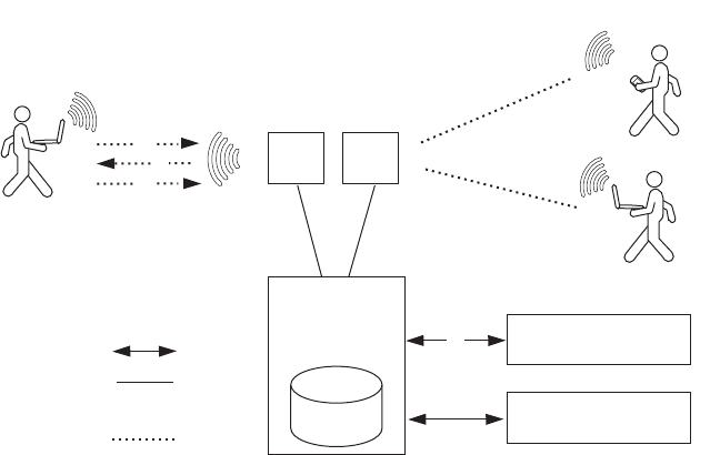
520 CHAPTER 22: CONFIGURING COMMUNICATION WITH RADIUS
Figure 33 Wireless Client, MAP, WX Switch, and RADIUS Servers
In the example shown in Figure 33, the following events occur:
1The wireless user (client) requests an IEEE 802.11 association from the
MAP.
2After the MAP creates the association, the WX switch sends an Extensible
Authentication Protocol (EAP) identity request to the client.
3The client sends an EAP identity response.
4From the EAP response, the WX switch gets the client’s username. The
WX switch then searches its AAA configuration, attempting to match the
client's username against the user globs in the AAA configuration.
When a match is found, the methods specified by the matching AAA
command in the WX configuration file indicate how the client is to be
authenticated, either locally on the WX switch, or via a RADIUS server
group.
5If the client does not support 802.1X, MSS attempts to perform MAC
authentication for the client instead. In this case, if the switch’s
configuration contains a set authentication mac command that
matches the client’s MAC address, MSS uses the method specified by the
command. Otherwise, MSS uses local MAC authentication by default.
(For information about MAC client authentication, see “Configuring
MAC Authentication and Authorization” on page 457.)
WX switch
with local
database
Wireless
connection
Wired
connection(s)
RADIUS Server 1
RADIUS Server 2
1
3
2
4
Client (with laptop)
Client (with laptop)
Client (with PDA)
MAPMAP

Before You Begin 521
Before You Begin To ensure that you can contact the RADIUS servers you plan to use for
authentication, send the ping command to each one to verify connectivity.
ping ip-address
You can then set up communication between the WX switch and each
RADIUS server group.
Configuring
RADIUS Servers
An authentication server authenticates each client with access to a switch
port before making available any services offered by the switch or the
wireless network. The authentication server can reside either in the local
database on the WX switch or on a remote RADIUS server.
When a RADIUS server is used for authentication, you must configure
RADIUS server parameters. For each RADIUS server, you must, at a
minimum, set the server name, the password (key), and the IP address.
You can include any or all of the other optional parameters. You can set
some parameters globally for the RADIUS servers.
For RADIUS servers that do not explicitly set their own dead time and
timeout timers and transmission attempts, MSS sets the following values
by default:
Dead time — 0 (zero) minutes (The WX switch does not designate
unresponsive RADIUS servers as unavailable.)
Transmission attempts — 3
Timeout (WX wait for a server response) — 5 seconds
When MSS sends an authentication or authorization request to a RADIUS
server, MSS waits for the amount of the RADIUS timeout for the server to
respond. If the server does not respond, MSS retransmits the request.
MSS sends the request up to the number of retransmits configured. (The
retransmit setting specifies the total number of attempts, including the
first attempt.) For example, using the default values, MSS sends a request
to a server up to three times, waiting 5 seconds between requests.
If a server does not respond before the last request attempt times out,
MSS holds down further requests to the server, for the duration of the
dead time. For example, if you set the dead time to 5 minutes, MSS stops
sending requests to the unresponsive server for 5 minutes before
reattempting to use the server.
522 CHAPTER 22: CONFIGURING COMMUNICATION WITH RADIUS
During the holddown, it is as if the dead RADIUS server does not exist.
MSS skips over any dead RADIUS servers to the next live server, or on to
the next method if no more live servers are available, depending on your
configuration. For example, if a RADIUS server group is the primary
authentication method and local is the secondary method, MSS fails over
to the local method if all RADIUS servers in the server group are
unresponsive and have entered the dead time.
For failover authentication or authorization to work promptly, 3Com
recommends that you change the dead time to a value other than 0.
With the default setting, the dead time is never invoked and MSS does
not hold down requests to unresponsive RADIUS servers. Instead, MSS
attempts to send each new authentication or authorization request to a
server even if the server is thought to be unresponsive. This behavior can
cause authentication or authorization failures on clients because MSS
does not fail over to the local method soon enough and the clients
eventually time out.
Configuring Global
RADIUS Defaults
You can change RADIUS values globally and set a global password (key)
with the following command. The key string is the shared secret that the
WX switch uses to authenticate itself to the RADIUS server.
set radius {deadtime minutes | encrypted-key string |
key string | retransmit number | timeout seconds}
(To override global settings for individual RADIUS servers, use the set
radius server command. See “Configuring Individual RADIUS Servers”
on page 523.)
For example, the following commands set the dead-time timer to
10 minutes and set the password to r8gney for all RADIUS servers in the
WX configuration:
WX1200# set radius deadtime 10
success: change accepted.
WX1200# set radius key r8gney
success: change accepted.
To reset global RADIUS server settings to their factory defaults, use the
following command:
clear radius {deadtime | key | retransmit | timeout}
Configuring RADIUS Servers 523
For example, the following command resets the dead-time timer to
0 minutes on all RADIUS servers in the WX configuration:
WX1200# clear radius deadtime
success: change accepted.
Setting the System IP
Address as the Source
Address
By default, RADIUS packets leaving the WX switch have the source IP
address of the outbound interface on the switch. This source address can
change when routing conditions change. If you have set a system IP
address for the WX switch, you can use it as a permanent source address
for the RADIUS packets sent by the switch.
To set the WX system IP address as the address of the RADIUS client, type
the following command:
WX1200# set radius client system-ip
success: change accepted.
To remove the WX switch’s system IP address from use as the source
address in RADIUS client requests from the switch to its RADIUS server(s),
type the following command:
WX1200# clear radius client system-ip
success: change accepted.
The command causes the WX to select a source interface address based
on information in its routing table as the RADIUS client address.
Configuring
Individual RADIUS
Servers
You must set up a name and IP address for each RADIUS server. To
configure a RADIUS server, use the following command:
set radius server server-name [address ip-address]
[key string]
The server name must be unique for this RADIUS server on this WX switch.
Do not use the same name for a RADIUS server and a RADIUS server group.
The key (password) string is the shared secret that the WX switch uses to
authenticate itself to the RADIUS server. (For additional options, see the
Wireless LAN Switch and Controller Command Reference.)
For example, the following command names a RADIUS server rs1 with the
IP address 192.168.0.2 and the key testing123:
WX1200# set radius server rs1 address 192.168.0.2 key
testing123
success: change accepted.

524 CHAPTER 22: CONFIGURING COMMUNICATION WITH RADIUS
You can configure multiple RADIUS servers. When you define server
names and keys, case is significant. For example:
WX1200# set radius server rs1 address 10.6.7.8 key seCret
success: change accepted.
WX1200# set radius server rs2 address 10.6.7.9 key BigSecret
success: change accepted.
You must provide RADIUS servers with names that are unique. To prevent
confusion, 3Com recommends that RADIUS server names differ in ways
other than case. For example, avoid naming two servers RS1 and rs1.
You must configure RADIUS servers into server groups before you can
access them. For information on creating server groups, see “Configuring
RADIUS Server Groups” on page 524.
Deleting RADIUS
Servers
To remove a RADIUS server from the WX configuration, use the following
command:
clear radius server server-name
Configuring
RADIUS Server
Groups
A server group is a named group of up to four RADIUS servers. Before
you can use a RADIUS server for authentication, you must first create a
RADIUS server group and add the RADIUS server to that group. You can
also arrange load balancing, so that authentications are spread out
among servers in the group. You must declare all members of a server
group, in contact order, when you create the group.
Once the group is configured, you can use a server group name as the
AAA method with the set authentication and set accounting
commands. (See Chapter 3, “Configuring AAA for Administrative and
Local Access,” on page 51 and Chapter 21, “Configuring AAA for
Network Users,” on page 433.)
Subsequently, you can change the members of a group or configure load
balancing.
If you add or remove a RADIUS server in a server group, all the RADIUS
dead timers for that server group are reset to the global default.

Configuring RADIUS Server Groups 525
Creating Server
Groups
To create a server group, you must first configure the RADIUS servers
with their addresses and any optional parameters. After configuring
RADIUS servers, type the following command:
set server group group-name members server-name1
[server-name2] [server-name3] [server-name4]
For example, to create a server group called shorebirds with the RADIUS
servers heron, egret, and sandpiper, type the following commands:
WX1200# set radius server egret address 192.168.253.1 key apple
WX1200# set radius server heron address 192.168.253.2 key pear
WX1200# set radius server sandpiper address 192.168.253.3 key plum
WX1200# set server group shorebirds members egret heron sandpiper
In this example, a request to shorebirds results in the RADIUS servers
being contacted in the order that they are listed in the server group
configuration, first egret, then heron, then sandpiper. You can change
the RADIUS servers in server groups at any time. (See “Adding Members
to a Server Group” on page 527.)
Any RADIUS servers that do not respond are marked dead (unavailable)
for a period of time. The unresponsive server is skipped over, as though it
did not exist, during its dead time. Once the dead time elapses, the server
is again a candidate for receiving requests. To change the default
dead-time timer, use the set radius or set radius server command.
Ordering Server Groups
You can configure up to four methods for authentication, authorization,
and accounting (AAA). AAA methods can be the local database on the
WX switch and/or one or more RADIUS server groups. You set the order
in which the WX switch attempts the AAA methods by the order in which
you enter the methods in CLI commands.
In most cases, if the first method results in a pass or fail, the evaluation is
final. If the first method does not respond or results in an error, the WX
switch tries the second method and so on.
However, if the local database is the first method in the list, followed by a
RADIUS server group, the WX switch responds to a failed search of the
database by sending a request to the following RADIUS server group. This
exception is called local override.
For more information, see “AAA Methods for IEEE 802.1X and Web
Network Access” on page 442.

526 CHAPTER 22: CONFIGURING COMMUNICATION WITH RADIUS
Configuring Load Balancing
You can configure the WX switch to distribute authentication requests
across RADIUS servers in a server group, which is called load balancing.
Distributing the authentication process across multiple RADIUS servers
significantly reduces the load on individual servers while increasing
resiliency on a systemwide basis.
When you configure load balancing, the first client’s RADIUS requests are
directed to the first server in the group, the second client’s RADIUS
requests are directed to the second server in the group, and so on. When
the last server in the group is reached, the cycle is repeated.
MSS attempts to send accounting records to one RADIUS server, even if
load balancing is configured.
To configure load balancing, use the following command:
set server group group-name load-balance enable
For example, to configure RADIUS servers pelican and seagull as the
server group swampbirds with load balancing:
1Configure the members of a server group by typing the following
command:
WX1200# set server group swampbirds members pelican seagull
success: change accepted.
2Enable load balancing by typing the following command:
WX1200# set server group swampbirds load-balance enable
success: change accepted.
The following command disables load balancing for a server group:
clear server group group-name load-balance
Configuring RADIUS Server Groups 527
Adding Members to a Server Group
To add RADIUS servers to a server group, type the following command:
set server group group-name members
server-name1 [server-name2] [server-name3] [server-name4]
The keyword members lists the RADIUS servers contained in the named
server group. A server group can contain between one and four RADIUS
servers. This command accepts any RADIUS servers as the current set of
servers. To change the server members, you must reenter all of them.
For example, to add RADIUS server coot to server group shorebirds:
1Determine the server group by typing the following command:
WX1200# display aaa
Radius Servers
Server Addr Ports T/o Tries Dead State
-------------------------------------------------------------------
sandpiper 192.168.253.3 1812 1813 5 3 0 UP
heron 192.168.253.1 1812 1813 5 3 0 UP
coot 192.168.253.4 1812 1813 5 3 0 UP
egret 192.168.253.2 1812 1813 5 3 0 UP
Server groups
shorebirds (load-balanced): sandpiper heron egret
The RADIUS server coot is configured but not part of the server group
shorebirds.
2To add RADIUS server coot as the last server in the server group
shorebirds, type the following command:
WX1200# set server group shorebirds members sandpiper heron egret coot
success: change accepted.
Deleting a Server
Group
To remove a server group, type the following command:
clear server group group-name
For example, to delete the server group shorebirds, type the following
command:
WX1200# clear server group shorebirds
success: change accepted.

528 CHAPTER 22: CONFIGURING COMMUNICATION WITH RADIUS
The members of the group remain configured, although no server groups
are shown:
WX1200# display aaa
Default Values
authport=1812 acctport=1813 timeout=5 acct-timeout=5
retrans=3 deadtime=0 key=(null) author-pass=(null)
Radius Servers
Server Addr Ports T/o Tries Dead State
-------------------------------------------------------------------
sandpiper 192.168.253.3 1812 1813 5 3 0 UP
heron 192.168.253.1 1812 1813 5 3 0 UP
coot 192.168.253.4 1812 1813 5 3 0 UP
egret 192.168.253.2 1812 1813 5 3 0 UP
Server groups
RADIUS and Server
Group
Configuration
Scenario
The following example illustrates how to declare four RADIUS servers to a
WX switch and configure them into two load-balancing server groups,
swampbirds and shorebirds:
1Configure RADIUS servers. Type the following commands:
WX1200# set radius server pelican address 192.168.253.11 key elm
WX1200# set radius server seagull address 192.168.243.12 key fir
WX1200# set radius server egret address 192.168.243.15 key pine
WX1200# set radius server sandpiper address 192.168.253.17 key oak
2Place two of the RADIUS servers into a server group called swampbirds.
Type the following command:
WX1200# set server group swampbirds members pelican seagull
3Enable load balancing for swampbirds. Type the following command:
WX1200# set server group swampbirds load-balance enable
4Place the other RADIUS servers in a server group called shorebirds. Type
the following command:
WX1200# set server group shorebirds members egret pelican
sandpiper
5Enable load balancing for shorebirds. Type the following command:
WX1200# set server group shorebirds load-balance enable
RADIUS and Server Group Configuration Scenario 529
6Display the configuration. Type the following command:
WX1200# display aaa
Default Values
authport=1812 acctport=1813 timeout=5 acct-timeout=5
retrans=3 deadtime=0 key=(null) author-pass=(null)
Radius Servers
Server Addr Ports T/o Tries Dead State
-------------------------------------------------------------------
sandpiper 192.168.253.17 1812 1813 5 3 0 UP
seagull 192.168.243.12 1812 1813 5 3 0 UP
egret 192.168.243.15 1812 1813 5 3 0 UP
pelican 192.168.253.11 1812 1813 5 3 0 UP
Server groups
swampbirds (load-balanced): pelican seagull
shorebirds (load-balanced): egret pelican sandpiper
530 CHAPTER 22: CONFIGURING COMMUNICATION WITH RADIUS

23 MANAGING 802.1X ON THE
WX SWITCH
Certain settings for IEEE 802.1X sessions on the WX switch are enabled
by default. For best results, change the settings only if you are aware of a
problem with the WX switch’s 802.1X performance. For settings that you
can reset with a clear command, MSS reverts to the default value.
See “Managing WEP Keys” on page 534 for information about changing
the settings for Wired-Equivalent Privacy protocol (WEP) key rotation
(rekeying).
CAUTION: 802.1X parameter settings are global for all SSIDs configured
on the WX switch.
Managing 802.1X
on Wired
Authentication
Ports
A wired authentication port is an Ethernet port that has 802.1X
authentication enabled for access control. Like wireless users, users that
are connected to a WX switch by Ethernet wire can be authenticated
before they can be authorized to use the network. One difference
between a wired authenticated user and a wireless authenticated user is
that data for wired users is not encrypted after the users are
authenticated.
By default, 802.1X authentication is enabled for wired authenticated
ports, but you can disable it. You can also set the port to unconditionally
authorize, or unconditionally reject, all users.
Enabling and
Disabling 802.1X
Globally
The following command globally enables or disables 802.1X
authentication on all wired authentication ports on a WX switch:
set dot1x authcontrol {enable | disable}
532 CHAPTER 23: MANAGING 802.1X ON THE WX SWITCH
The default setting is enable, which permits 802.1X authentication to
occur as determined by the set dot1X port-control command for each
wired authentication port. The disable setting forces all wired
authentication ports to unconditionally authorize all 802.1X
authentication attempts by users with an EAP success message.
To reenable 802.1X authentication on wired authentication ports, type
the following command:
WX1200# set dot1x authcontrol enable
success: dot1x authcontrol enabled.
Setting 802.1X Port
Control
The following command specifies the way a wired authentication port or
group of ports handles user 802.1X authentication attempts:
set dot1x port-control
{forceauth | forceunauth | auto} port-list
The default setting is auto, which allows the WX switch to process
802.1X authentication normally according to the authentication
configuration. Alternatively, you can set a wired authentication port or
ports to either unconditionally authenticate or unconditionally reject all
users.
For example, the following command forces port 1 to unconditionally
authenticate all 802.1X authentication attempts with an EAP success
message:
WX1200# set dot1x port-control forceauth 1
success: authcontrol for 1 is set to FORCE-AUTH.
Similarly, the following command forces port 2 to unconditionally reject
any 802.1X attempts with an EAP failure message:
WX1200# set dot1x port-control forceunauth 2
success: authcontrol for 2 is set to FORCE-UNAUTH.
The set dot1x port-control command is overridden by the set dot1x
authcontrol command. The clear dot1x port-control command
returns port control to the default auto value.
Type the following command to reset port control for all wired
authentication ports:
WX1200# clear dot1x port-control
success: change accepted.

Managing 802.1X Encryption Keys 533
Managing 802.1X
Encryption Keys
By default, the WX switch sends encryption key information to a wireless
supplicant (client) in an Extensible Authentication Protocol over LAN
(EAPoL) packet after authentication is successful. You can disable this
feature or change the time interval for key transmission.
The secret Wired-Equivalent Privacy protocol (WEP) keys used by MSS on
MAPs for broadcast communication on a VLAN are automatically rotated
(rekeyed) every 30 minutes to maintain secure packet transmission. You
can disable WEP key rotation for debugging purposes, or change the
rotation interval.
Enabling 802.1X Key
Transmission
The following command enables or disables the transmission of key
information to the supplicant (client) in EAPoL key messages, after
authentication:
set dot1x key-tx {enable | disable}
Key transmission is enabled by default.
The WX switch sends EAPoL key messages after successfully
authenticating the supplicant (client) and receiving authorization
attributes for the client. If the client is using dynamic WEP, the EAPoL Key
messages are sent immediately after authorization.
Type the following command to reenable key transmission:
WX1200# set dot1x key-tx enable
success: dot1x key transmission enabled.
Configuring 802.1X
Key Transmission
Time Intervals
The following command sets the number of seconds the WX switch waits
before retransmitting an EAPoL packet of key information:
set dot1x tx-period seconds
The default is 5 seconds. The range for the retransmission interval is from
1 to 65,535 seconds. For example, type the following command to set
the retransmission interval to 300 seconds:
WX1200# set dot1x tx-period 300
success: dot1x tx-period set to 300.

534 CHAPTER 23: MANAGING 802.1X ON THE WX SWITCH
Type the following command to reset the retransmission interval to the
5-second default:
WX1200# clear dot1x tx-period
success: change accepted.
Managing WEP Keys Wired-Equivalent Privacy (WEP) is part of the system security of 802.1X.
MSS uses WEP to provide confidentiality to packets as they are sent over
the air. WEP operates on the MAP.
WEP uses a secret key shared between the communicators. WEP rekeying
increases the security of the network. New unicast keys are generated
every time a client performs 802.1X authentication.
The rekeying process can be performed automatically on a periodic basis.
By setting the Session-Timeout RADIUS attribute, you make the
reauthentication transparent to the client, who is unaware that
reauthentication is occurring. A good value for Session-Timeout is
30 minutes.
WEP broadcast rekeying causes the broadcast and multicast keys for WEP
to be rotated every WEP rekey period for each radio to each connected
VLAN. The WX switch generates the new broadcast and multicast keys
and pushes the keys to the clients via EAPoL key messages. WEP keys are
case-insensitive.
Use the set dot1x wep-rekey and the set dot1x wep-rekey-period
commands to enable WEP key rotation and configure the time interval for
WEP key rotation.
Configuring 802.1X WEP Rekeying
WEP rekeying is enabled by default on the WX switch. Disable WEP
rekeying only if you need to debug your 802.1X network.
Use the following command to disable WEP rekeying for broadcast and
multicast keys:
WX1200# set dot1x wep-rekey disable
success: wep rekeying disabled
Reauthentication is not required for using this command. Broadcast and
multicast keys are always rotated at the same time, so all members of a
given radio and VLAN receive the new keys at the same time.

Setting EAP Retransmission Attempts 535
To reenable WEP rekeying, type the following command:
WX1200# set dot1x wep-rekey enable
success: wep rekeying enabled
Configuring the Interval for WEP Rekeying
The following command sets the interval for rotating the WEP broadcast
and multicast keys:
set dot1x wep-rekey-period seconds
The default is 1800 seconds (30 minutes). You can set the interval from
30 to 1,641,600 seconds (19 days). For example, type the following
command to set the WEP-rekey period to 900 seconds:
WX1200# set dot1x wep-rekey-period 900
success: dot1x wep-rekey-period set to 900
Setting EAP
Retransmission
Attempts
The following command sets the maximum number of times the WX
switch retransmits an 802.1X-encapsulated EAP request to the supplicant
(client) before it times out the authentication session:
set dot1x max-req number-of-retransmissions
The default number of retransmissions is 2. You can specify from 0 to 10
retransmit attempts. For example, type the following command to set the
maximum number of retransmission attempts to 3:
WX1200# set dot1x max-req 3
success: dot1x max request set to 3.
To reset the number of retransmission attempts to the default setting,
type the following command:
WX1200# clear dot1x max-req
success: change accepted.
To support SSIDs that have both 802.1X and static WEP clients, MSS
sends a maximum of two ID requests, even if this parameter is set to a
higher value. Setting the parameter to a higher value does affect all other
types of EAP messages.
The amount of time MSS waits before it retransmits an
802.1X-encapsulated EAP request to the supplicant is the same number
of seconds as one of the following timeouts:

536 CHAPTER 23: MANAGING 802.1X ON THE WX SWITCH
Supplicant timeout (configured by the set dot1x timeout supplicant
command)
RADIUS session-timeout attribute
If both of these timeouts are set, MSS uses the shorter of the two. If the
RADIUS session-timeout attribute is not set, MSS uses the timeout
specified by the set dot1x timeout supplicant command, by default 30
seconds.
Managing 802.1X
Client
Reauthentication
Reauthentication of 802.1X wireless supplicants (clients) is enabled on
the WX switch by default. By default, the WX switch waits 3600 seconds
(1 hour) between authentication attempts. You can disable
reauthentication or change the defaults.
You also can use the RADIUS session-timeout attribute to set the
reauthentication timeout for a specific client. In this case, MSS uses the
timeout that has the lower value. If the session-timeout is set to fewer
seconds than the global reauthentication timeout, MSS uses the
session-timeout for the client. However, if the global reauthentication
timeout is shorter than the session-timeout, MSS uses the global timeout
instead.
Enabling and
Disabling 802.1X
Reauthentication
The following command enables or disables the reauthentication of
supplicants (clients) by the WX switch:
set dot1x reauth {enable | disable}
Reauthentication is enabled by default.
Type the following command to reenable reauthentication of clients:
WX1200# set dot1x reauth enable
success: dot1x reauthentication enabled.
Setting the Maximum
Number of 802.1X
Reauthentication
Attempts
The following command sets the number of reauthentication attempts
that the WX switch makes before the supplicant (client) becomes
unauthorized:
set dot1x reauth-max number-of-attempts

Managing 802.1X Client Reauthentication 537
The default number of reauthentication attempts is 2. You can specify
from 1 to 10 attempts. For example, type the following command to set
the number of authentication attempts to 8:
WX1200# set dot1x reauth-max 8
success: dot1x max reauth set to 8.
Type the following command to reset the maximum number of
reauthorization attempts to the default:
WX1200# clear dot1x reauth-max
success: change accepted.
If the number of reauthentications for a wired authentication client is
greater than the maximum number of reauthentications allowed, MSS
sends an EAP failure packet to the client and removes the client from the
network. However, MSS does not remove a wireless client from the
network under these circumstances.
Setting the 802.1X
Reauthentication
Period
The following command configures the number of seconds that the WX
switch waits before attempting reauthentication:
set dot1x reauth-period seconds
The default is 3600 seconds (1 hour). The range is from 60 to
1,641,600 seconds (19 days). This value can be overridden by user
authorization parameters.
MSS reauthenticates dynamic WEP clients based on the reauthentication
timer. MSS also reauthenticates WPA clients if the clients use the WEP-40
or WEP-104 cipher. For each dynamic WEP client or WPA client using a
WEP cipher, the reauthentication timer is set to the lesser of the global
setting or the value returned by the AAA server with the rest of the
authorization attributes for that client.
For example, type the following command to set the number of seconds
to 100 before reauthentication is attempted:
WX1200# set dot1x reauth-period 100
success: dot1x auth-server timeout set to 100.
Type the following command to reset the default timeout period:
WX1200# clear dot1x reauth-period
success: change accepted.

538 CHAPTER 23: MANAGING 802.1X ON THE WX SWITCH
Setting the Bonded
Authentication
Period
The following command changes the Bonded Auth™ (bonded
authentication) period, which is the number of seconds MSS retains
session information for an authenticated machine while waiting for the
802.1X client on the machine to start (re)authentication for the user.
Normally, the Bonded Auth period needs to be set only if the network has
Bonded Auth clients that use dynamic WEP, or use WEP-40 or WEP-104
encryption with WPA or RSN. These clients can be affected by the 802.1X
reauthentication parameter or the RADIUS Session-Timeout parameter.
To set the Bonded Auth period, use the following command:
set dot1x bonded-period seconds
The Bonded Auth period applies only to 802.1X authentication rules that
contain the bonded option.
To reset the Bonded Auth period to its default value, use the following
command:
clear dot1x max-req
(For more information about Bonded Auth, see “Binding User
Authentication to Machine Authentication” on page 451.)
Managing Other
Timers
By default, the WX switch waits 60 seconds before responding to a client
whose authentication failed, and times out a request to a RADIUS server
or an authentication session with a client after 30 seconds. You can
modify these defaults.
Setting the 802.1X
Quiet Period
The following command configures the number of seconds a WX switch
remains quiet and does not respond to a supplicant (client) after a failed
authentication:
set dot1x quiet-period seconds
The default is 60 seconds. The acceptable range is from 0 to
65,535 seconds.
For example, type the following command to set the quiet period to
300 seconds:
WX1200# set dot1x quiet-period 300
success: dot1x quiet period set to 300.
Managing Other Timers 539
Type the following command to reset the 802.1X quiet period to the
default:
WX1200# clear dot1x quiet-period
success: change accepted.
Setting the 802.1X
Timeout for an
Authorization Server
Use this command to configure the number of seconds before the WX
switch times out a request to a RADIUS authorization server.
set dot1x timeout auth-server seconds
The default is 30 seconds. The range is from 1 to 65,535 seconds.
For example, type the following command to set the authorization server
timeout to 60 seconds:
WX1200# set dot1x timeout auth-server 60
success: dot1x auth-server timeout set to 60.
To reset the 802.1X authorization server timeout to the default, type the
following command:
WX1200# clear dot1x timeout auth-server
success: change accepted.
Setting the 802.1X
Timeout for a Client
Use the following command to set the number of seconds before the WX
switch times out an authentication session with a supplicant (client):
set dot1x timeout supplicant seconds
The default is 30 seconds. The range of time is from 1 to 65,535 seconds.
For example, type the following command to set the number of seconds
for a timeout to 300:
WX1200# set dot1x timeout supplicant 300
success: dot1x supplicant timeout set to 300.
Type the following command to reset the timeout period:
WX1200# clear dot1x timeout supplicant
success: change accepted.

540 CHAPTER 23: MANAGING 802.1X ON THE WX SWITCH
Displaying 802.1X
Information
This command displays 802.1X information for clients, statistics, VLANs,
and configuration.
display dot1x {clients | stats | config}
display dot1x clients displays the username, MAC address, VLAN,
and state of active 802.1X clients.
display dot1x config displays a summary of the current
configuration.
display dot1x stats displays global 802.1X statistical information
associated with connecting and authenticating.
Viewing 802.1X
Clients
Type the following command to display active 802.1X clients:
WX1200# display dot1x clients
MAC Address State Vlan Identity
------------- ------- ------ ----------
00:20:a6:48:01:1f Connecting (unknown)
00:05:3c:07:6d:7c Authenticated vlan-it EXAMPLE\smith
00:05:5d:7e:94:83 Authenticated vlan-eng EXAMPLE\jgarcia
00:02:2d:86:bd:38 Authenticated vlan-eng wong@exmpl.com
00:05:5d:7e:97:b4 Authenticated vlan-eng EXAMPLE\hosni
00:05:5d:7e:98:1a Authenticated vlan-eng EXAMPLE\tsmith
00:0b:be:a9:dc:4e Authenticated vlan-pm havel@corp.com
00:05:5d:7e:96:e3 Authenticated vlan-eng EXAMPLE\geetha
00:02:2d:6f:44:77 Authenticated vlan-eng EXAMPLE\tamara
00:05:5d:7e:94:89 Authenticated vlan-eng EXAMPLE\nwong
00:06:80:00:5c:02 Authenticated vlan-eng EXAMPLE\hhabib
00:02:2d:6a:de:f2 Authenticated vlan-pm smith@exmpl.com
00:02:2d:5e:5b:76 Authenticated vlan-pm EXAMPLE\natasha
00:02:2d:80:b6:e1 Authenticated vlan-cs jjg@exmpl.com
00:30:65:16:8d:69 Authenticated vlan-wep MAC authenticated
00:02:2d:64:8e:1b Authenticated vlan-eng EXAMPLE\jose
Viewing the 802.1X
Configuration
Type the following command to display the 802.1X configuration:
WX1200# display dot1x config
802.1X user policy
----------------------
'EXAMPLE\pc1' on ssid 'mycorp' doing EAP-PEAP (EAP-MSCHAPv2)
'EXAMPLE\bob' on ssid 'mycorp' doing EAP-PEAP (EAP-MSCHAPv2)
(bonded)
Displaying 802.1X Information 541
802.1X parameter setting
---------------- -------
supplicant timeout 30
auth-server timeout 30
quiet period 5
transmit period 5
reauthentication period 3600
maximum requests 2
key transmission enabled
reauthentication enabled
authentication control enabled
WEP rekey period 1800
WEP rekey enabled
Bonded period 60
port 5, authcontrol: auto, max-sessions: 16
port 6, authcontrol: auto, max-sessions: 1
Viewing 802.1X
Statistics
Type the following command to display 802.1X statistics about
connecting and authenticating:
WX1200# display dot1x stats
802.1X statistic value
---------------- -----
Enters Connecting: 709
Logoffs While Connecting: 112
Enters Authenticating: 467
Success While Authenticating: 0
Timeouts While Authenticating: 52
Failures While Authenticating: 0
Reauths While Authenticating: 0
Starts While Authenticating: 31
Logoffs While Authenticating: 0
Starts While Authenticated: 85
Logoffs While Authenticated: 1
Bad Packets Received: 0
For information about the fields in the output, see the Wireless LAN
Switch and Controller Command Reference.
542 CHAPTER 23: MANAGING 802.1X ON THE WX SWITCH

24 CONFIGURING SODA ENDPOINT
SECURITY FOR A WX SWITCH
Sygate On-Demand (SODA) is an endpoint security solution that allows
enterprises to enforce security policies on client devices without having to
install any special software on the client machines. MSS can be
configured to run SODA security checks on users’ machines as a
requirement for gaining access to the network.
About SODA
Endpoint Security
The SODA endpoint security solution consists of six modules that provide
on-demand security:
Virtual Desktop – Protects confidential data by virtualizing the
desktop, applications, file-system, registry, printing, removable media,
and copy/paste functions. All data is encrypted on-the-fly and can
optionally be erased upon session termination. The virtual desktop is
isolated from the normal desktop, protecting the session from
previous infection.
Host Integrity – Tests the security of the desktop to determine how
much access to network resources the device should be granted. Host
integrity checks include:
Ensuring that an anti-virus product is running with up-to-date virus
definitions
Ensuring that a personal firewall is active
Checking that service pack levels are met
Ensuring that critical patches are installed
Custom checks can be implemented based on the existence of specific
registry keys/values, applications, files, or operating system platforms.
Network access can also be prevented based on the existence of
specific processes.
544 CHAPTER 24: CONFIGURING SODA ENDPOINT SECURITY FOR A WX SWITCH
Malicious Code Protection – Detects and blocks keystroke loggers
that capture usernames and passwords, Trojans that create back-door
user accounts, and Screen Scrapers that spy on user activity.
The Malicious Code module integrates a Virtual Keyboard function
that requires users to input confidential information such as
passwords using the Virtual Keyboard when accessing specific Web
sites, to protect against hardware keystroke loggers. This module uses
a combination of signatures for known exploits and behavioral
detection to protect against unknown threats.
Cache Cleaner – Ensures that Web browser information, such as
cookies, history, auto-completion data, stored passwords, and
temporary files are erased or removed upon termination of the user’s
session, inactivity timeout, or closing of the browser.
Connection Control – Controls network connections based on
Domain, IP address, Port, and Service. For example, Connection
Control can prevent a Trojan from sending out a confidential
document, downloaded legitimately through an SSL VPN tunnel, to a
malicious e-mail server (SMTP) using a second network tunnel.
Adaptive Policies – Sense the type and location of device and adjusts
access based on endpoint parameters such as IP range, registry keys,
and DNS settings
The SODA endpoint security modules are configured through Sygate
On-Demand Manager (SODA Manager), a Windows application.
SODA Manager is used to create a SODA agent, which is a Java applet
that is downloaded by client devices when they attempt to gain access
to the network. Once downloaded, the SODA agent runs a series of
security checks to enforce endpoint security on the client device.
SODA Endpoint
Security Support on
WX Switches
WX switches support SODA endpoint security functionality in the
following ways:
SODA agent applets can be uploaded to a WX switch, stored there,
and downloaded by clients attempting to connect to the network.
The WX switch can ensure that clients run the SODA agent security
checks successfully prior to allowing them access to the network.
Different sets of security checks can be downloaded and run, based
on the SSID being used by the client.
About SODA Endpoint Security 545
If the security checks fail, the WX switch can deny the client access to
the network, or grant the client limited access based on a configured
security ACL.
When the client closes the Virtual Desktop, the WX switch can
optionally disconnect the client from the network.
How SODA
Functionality Works
on WX Switches
This section describes how the SODA functionality is configured to work
with a WX switch, and the procedure that takes place when a user
attempts to connect to an SSID where the SODA functionality is enabled.
Note that in the current release, the SODA functionality works only in
conjunction with the Web Portal WebAAA feature.
SODA functionality on a WX switch is configured as follows:
1Using SODA Manager, a network administrator creates a SODA agent
based on the security needs of the network.
2The network administrator exports the SODA agent files from SODA
Manager, and saves them as a .zip file.
3The SODA agent .zip file is uploaded to the WX switch using TFTP.
4The SODA agent files are installed on the WX switch using a CLI
command that extracts the files from the .zip file and places them into a
specified directory.
5SODA functionality is enabled for an SSID that also has Web Portal
WebAAA configured.
Once configured, SODA functionality works as follows:
1A user connects to a MAP managed by a service profile where SODA
functionality is enabled.
2Since the Web Portal WebAAA feature is enabled for the SSID, a portal
session is started for the user, and the user is placed in the VLAN
associated with the web-portal-ssid or web-portal-wired user.
3The user opens a browser window and is redirected to a login page,
where he or she enters a username and password.
4The user is redirected to a page called index.html, which exists in the
SODA agent directory on the WX switch.
5The redirection to the index.html page causes the SODA agent files to be
downloaded to the user’s computer.

546 CHAPTER 24: CONFIGURING SODA ENDPOINT SECURITY FOR A WX SWITCH
6Once the SODA agent files have been downloaded, one of the following
can take place:
aIf the WX switch is configured to enforce the SODA agent security
checks (the default), then the SODA agent checks are run on the user’s
computer. If the user’s computer passes the checks, then a
customizable success page is loaded in the browser window. The user
is then moved from the portal VLAN to his or her configured VLAN
and granted access to the network.
bIf the WX switch is configured not to enforce the SODA agent security
checks, then the user is moved from the portal VLAN to his or her
configured VLAN and granted access to the network, without waiting
for the SODA agent checks to be completed.
cIf the user’s computer fails one of the SODA agent checks, then a
customizable failure page is loaded in the browser window. The user is
then disconnected from the network, or can optionally be granted
limited network access, based on a specified security ACL.
7At the completion of his or her session, the user can close the SODA
Virtual Desktop or point to an advertised logout URL. Either of these
actions cause a customizable logout page to be loaded in the browser
window. Accessing the logout page causes the user to be disconnected
from the network.
Configuring SODA
Functionality
Configuring SODA functionality on a WX switch consists of the following
tasks:
1Configure Web Portal WebAAA for the service profile. See “Configuring
Web Portal WebAAA for the Service Profile” on page 547.
2Using SODA manager, create the SODA agent. See “Creating the SODA
Agent with SODA Manager” on page 547.
3Copy the SODA agent to the WX switch. See “Copying the SODA Agent
to the WX Switch” on page 549.
4Install the SODA agent files in a directory on the WX switch. See
“Installing the SODA Agent Files on the WX Switch” on page 549.
5Enable SODA functionality for the service profile. See “Enabling SODA
Functionality for the Service Profile” on page 550.
6Specify whether to require clients to pass SODA agent checks to gain
access to the network (optional). See “Disabling Enforcement of SODA
Agent Checks” on page 550.
Configuring SODA Functionality 547
7Specify a page for a client to load when the SODA agent checks run
successfully (optional). See “Specifying a SODA Agent Success Page” on
page 551.
8Specify a page for a client to load when the SODA agent checks fail
(optional). See “Specifying a SODA Agent Failure Page” on page 551.
9Specify an ACL to apply to a client when it fails the SODA agent checks
(optional) See “Specifying a Remediation ACL” on page 552.
10 Specify a page for a client to load when logging out of the network
(optional). See “Specifying a SODA Agent Logout Page” on page 553.
11 Specify an alternate name for the directory where the SODA agent files
for a service profile are located (optional). See “Specifying an Alternate
SODA Agent Directory for a Service Profile” on page 554.
12 Remove the SODA agent files from the WX switch (optional). See
“Uninstalling the SODA Agent Files from the WX Switch” on page 554.
Configuring Web
Portal WebAAA for
the Service Profile
In the current release, SODA functionality works in conjunction with the
Web Portal AAA feature. Consequently, Web Portal AAA must be
enabled for the service profile for which you want to configure SODA
functionality.
See “Configuring Web Portal WebAAA” on page 460 for information on
configuring this feature.
Creating the SODA
Agent with SODA
Manager
Sygate On-Demand Manager (SODA Manager) is a Windows application
used for configuring security policies based on locations, and for creating
agents that enforce those security policies. For information on how to use
SODA Manager to create security policies, see the documentation that
came with the product.
You can use SODA Manager to create a SODA agent, configuring the
level of security desired according to the requirements of your network.
When a SODA agent is created (by pressing the Apply button in SODA
Manager), a subdirectory called On-DemandAgent is created in the
C:\Program Files\Sygate\Sygate On-Demand directory.
You place the contents of the On-DemandAgent directory into a .zip file
(for example, soda.ZIP) and copy the file to the WX switch using TFTP, as
described in “Copying the SODA Agent to the WX Switch” on page 549.
548 CHAPTER 24: CONFIGURING SODA ENDPOINT SECURITY FOR A WX SWITCH
Note the following when creating the SODA agent in SODA Manager:
The failure.html and success.html pages, when specified as success or
failure URLs in SODA Manager, must be of the format:
https://hostname/soda/ssid/xxx.html
where xxx refers to the name of the HTML file being accessed.
The success and failure URLs configured in SODA Manager are
required to have two keywords in them: /soda/ and success.html or
failure.html. The /soda/ keyword must immediately follow the
hostname. The hostname must match the Common Name specified in
the WebAAA certificate.
The logout page is required to have /logout.html in the URL.
The hostname of the logout page should be set to a name that
resolves to the WX switch’s IP address on the VLAN where the client
resides, or should be the IP address of the WX switch on the Web
Portal WebAAA VLAN; for example:
https://10.1.1.1/logout.html
The logout page should not point to a certificate hostname that is
unreachable from the client’s VLAN, nor should it point to an IP
address that is on a different VLAN, which causes the source MAC
address to be changed to the default router’s (gateway’s) MAC
address. The WX switch uses the client’s source MAC address and
source IP address combination to make sure the client is permitted to
log itself out.
If the source IP address is on a different VLAN, then the source MAC
address does not match with the session’s MAC address, and the
logout procedure fails.
Following the hostname, the URL of the logout page must exactly
match logout.html. You cannot specify any other subdirectories in the
URL.
Do not use the Partner Integration button in SODA Manager to
create agent files.
Configuring SODA Functionality 549
Copying the SODA
Agent to the WX
Switch
After creating the SODA agent with SODA manager, you copy the .zip file
to the WX switch using TFTP.
For example, the following command copies the soda.ZIP file from a TFTP
server to the WX switch:
WX1200# copy tftp://172.21.12.247/soda.ZIP soda.ZIP
....................................success: received
2912917 bytes in
11.230 seconds [ 259387 bytes/sec]
success: copy complete.
Installing the SODA
Agent Files on the
WX Switch
After copying the .zip file containing the SODA agent files to the WX
switch, you install the SODA agent files into a directory using the
following command:
install soda agent agent-file agent-directory directory
This command creates the specified directory, unzips the specified
agent-file and places the contents of the file into the directory. If the
directory has the same name as an SSID, then that SSID uses the SODA
agent files in the directory if SODA functionality is enabled for the service
profile that manages the SSID.
For example, the following command installs the contents of the file
soda.ZIP into a directory called sp1.
WX1200# install soda agent soda.ZIP agent-directory sp1
This command may take up to 20 seconds...
WX1200#
If SODA functionality is enabled for the service profile that manages
SSID sp1, then SODA agent files in this directory are downloaded to
clients attempting to connect to SSID sp1.
550 CHAPTER 24: CONFIGURING SODA ENDPOINT SECURITY FOR A WX SWITCH
Enabling SODA
Functionality for the
Service Profile
To enable SODA functionality for a service profile, use the following
command:
set service-profile name soda mode {enable | disable}
When SODA functionality is enabled for a service profile, a SODA agent is
downloaded to clients attempting to connect to a MAP managed by the
service profile. The SODA agent performs a series of security-related
checks on the client. By default, enforcement of SODA agent checks is
enabled, so that a connecting client must pass the SODA agent checks in
order to gain access to the network.
For example, the following command enables SODA functionality for
service profile sp1:
WX1200# set service-profile sp1 soda mode enable
success: change accepted.
Disabling
Enforcement of SODA
Agent Checks
When SODA functionality is enabled for a service profile, by default the
SODA agent checks are downloaded to a client and run before the client
is allowed on the network. You can optionally disable the enforcement of
the SODA security checks, so that the client is allowed access to the
network immediately after the SODA agent is downloaded, rather than
waiting for the security checks to be run.
To disable (or re-enable) the enforcement of the SODA security checks,
use the following command:
set service-profile name enforce-checks {enable | disable}
For example, the following command disables the enforcement of the
SODA security checks, allowing network access to clients after they have
downloaded the SODA agent, but without requiring that the SODA
agent checks be completed:
WX1200# set service-profile sp1 enforce-checks disable
success: change accepted.
Note that if you disable the enforcement of the SODA security checks,
you cannot apply the success and failure URLs to client devices. In
addition, you should not configure the SODA agent to refer to the
success and failure pages on the WX switch if you have disabled
enforcement of SODA agent checks.
Configuring SODA Functionality 551
Specifying a SODA
Agent Success Page
When a client successfully runs the checks performed by the SODA agent,
by default a dynamically generated page is displayed on the client
indicating that the checks succeeded. You can optionally create a custom
success page that is displayed on the client instead of the dynamically
generated one.
To specify a page that is loaded when a client passes the security checks
performed by the SODA agent, use the following command:
set service-profile name soda success-page page
To reset the success page to the default value, use the following
command:
clear service-profile name soda success-page
The page refers to a file on the WX switch. After this page is loaded, the
client is placed in its assigned VLAN and granted access to the network.
For example, the following command specifies success.html, which is a
file in the root directory on the WX switch, as the page to load when a
client passes the SODA agent checks:
WX1200# set service-profile sp1 soda success-page
success.html
success: change accepted.
The following command specifies success.html, in the soda-files directory
on the WX switch, as the page to load when a client passes the SODA
agent checks:
WX1200# set service-profile sp1 soda success-page
soda-files/success.html
success: change accepted.
Specifying a SODA
Agent Failure Page
When the SODA agent checks fail, by default a dynamically generated
page is displayed on the client indicating that the checks failed. You can
optionally create a custom failure page that is displayed on the client
instead of the dynamically generated one.
To specify a page that is loaded when a client fails the security checks
performed by the SODA agent, use the following command:
set service-profile name soda failure-page page
552 CHAPTER 24: CONFIGURING SODA ENDPOINT SECURITY FOR A WX SWITCH
To reset the failure page to the default value, use the following
command:
clear service-profile name soda failure-page
The page refers to a file on the WX switch. After this page is loaded, the
specified remediation ACL takes effect, or if there is no remediation ACL
configured, then the client is disconnected from the network.
For example, the following command specifies failure.html, which is a file
in the root directory on the WX switch, as the page to load when a client
fails the SODA agent checks:
WX1200# set service-profile sp1 soda failure-page
failure.html
success: change accepted.
The following command specifies failure.html, in the soda-files directory
on the WX switch, as the page to load when a client fails the SODA agent
checks:
WX1200# set service-profile sp1 soda failure-page
soda-files/failure.html
success: change accepted.
Specifying a
Remediation ACL
If the SODA agent checks fail on a client, by default the client is
disconnected from the network. Optionally, you can specify a failure page
for the client to load (with the set service-profile soda failure-page
command, described above). You can optionally specify a remediation
ACL to apply to the client when the failure page is loaded. The
remediation ACL can be used to grant the client limited access to
network resources, for example:
To specify a remediation ACL to be applied to a client if it fails the checks
performed by the SODA agent, use the following command:
set service-profile name soda remediation-acl acl-name
To disable use of the remediation ACL for the service profile, use the
following command:
clear service-profile name soda remediation-acl
The acl-name refers to an existing security ACL. If there is no remediation
ACL configured for the service profile, then the client is disconnected
from the network when the failure page is loaded.
Configuring SODA Functionality 553
If configured, a remediation ACL is applied to a client when the client
loads the failure page. A client loads the failure page only if the service
profile is set to enforce SODA agent checks, and the client fails the SODA
agent checks. Consequently, in order to apply a remediation ACL to a
client, you must make sure the service profile is set to enforce SODA
agent checks.
For example, the following command configures the WX switch to apply
acl-1 to a client when it loads the failure page:
WX1200# set service-profile sp1 soda remediation-acl acl-1
success: change accepted.
Specifying a SODA
Agent Logout Page
When a client closes the SODA virtual desktop, the client is automatically
disconnected from the network. You can optionally specify a page that is
loaded when the client logs out of the network. To do this, use the
following command:
set service-profile name soda logout-page page
To reset the logout page to the default value, use the following
command:
clear service-profile name soda logout-page
The page refers to a file on the WX switch.
For the logout page to load properly, you must enable the HTTPS server
on the WX switch, so that clients can access the page using HTTPS. To do
this, use the following command:
set ip https server enable
The client can request this page at any time, to ensure that the client’s
session has been terminated. You can add the IP address of the WX
switch to the DNS server as a well-known name, and you can advertise
the URL of the page to users as a logout page.
For example, the following command specifies logout.html, which is a file
in the root directory on the WX switch, as the page to load when a client
closes the SODA virtual desktop:
WX1200# set service-profile sp1 soda logout-page logout.html
success: change accepted.
554 CHAPTER 24: CONFIGURING SODA ENDPOINT SECURITY FOR A WX SWITCH
The following command specifies logout.html, in the soda-files directory on the
WX switch, as the page to load when a client closes the SODA virtual desktop:
WX# set service-profile sp1 soda logout-page
soda-files/logout.html
success: change accepted.
During authentication, a pop-under window appears behind the client’s
browser. The window contains a button labeled “End Session”. The client
can click this button to terminate the session.
Specifying an
Alternate SODA
Agent Directory for a
Service Profile
By default, the WX switch expects SODA agent files for a service profile to
be located in a directory with the same name as the SSID configured for
the service profile. You can optionally specify a different directory for the
SODA agent files used for a service profile. To do this, use the following
command:
set service-profile name soda agent-directory directory
To reset the SODA agent directory to the default value, use the following
command:
clear service-profile name soda agent-directory
If the same SODA agent is used for multiple service profiles, you can
specify a single directory for SODA agent files on the WX switch, rather
than placing the same SODA agent files in a separate directory for each
service profile.
For example, the following command specifies soda-agent as the location
for SODA agent files for service profile sp1:
WX1200# set service-profile sp1 soda agent-directory
soda-agent
success: change accepted.
Uninstalling the
SODA Agent Files
from the WX Switch
To remove the directory on the WX switch that contains SODA agent files,
use the following command:
uninstall soda agent agent-directory directory
This command removes the SODA agent directory and all of its contents. All
files in the specified directory are removed. The command removes the
directory and its contents, regardless of whether it contains SODA agent files.
Configuring SODA Functionality 555
For example, the following command removes the directory sp1 and all of
its contents:
WX1200# uninstall soda agent agent-directory sp1
This will delete all files in agent-directory, do you wish to
continue? (y|n) [n]y
Displaying SODA
Configuration
Information
To view information about the SODA configuration for a service profile,
use the display service profile command.
The following is an example of the output of the display service profile
command for service profile sp1. In the example, the fields related to
SODA functionality are highlighted in bold.
WX1200# display service-profile sp1
ssid-name: corp2 ssid-type: crypto
Beacon: yes Proxy ARP: no
DHCP restrict: no No broadcast: no
Short retry limit: 5 Long retry limit: 5
Auth fallthru: none Sygate On-Demand (SODA): yes
Enforce SODA checks: yes SODA remediation ACL:
Custom success web-page: Custom failure web-page:
Custom logout web-page: Custom agent-directory:
Static COS: no COS: 0
CAC mode: none CAC sessions: 14
User idle timeout: 180 Idle client probing: yes
Keep initial vlan: no Web Portal Session Timeout: 5
Web Portal ACL:
WEP Key 1 value: <none> WEP Key 2 value: <none>
WEP Key 3 value: <none> WEP Key 4 value: <none>
WEP Unicast Index: 1 WEP Multicast Index: 1
Shared Key Auth: NO
WPA enabled:
ciphers: cipher-tkip
authentication: 802.1X
TKIP countermeasures time: 60000ms
vlan-name = orange
session-timeout = 300
service-type = 2
11a beacon rate: 6.0 multicast rate: AUTO
11a mandatory rate: 6.0,12.0,24.0 standard rates: 9.0,18.0,36.0,48.0,54.0
11b beacon rate: 2.0 multicast rate: AUTO
11b mandatory rate: 1.0,2.0 standard rates: 5.5,11.0
11g beacon rate: 2.0 multicast rate: AUTO
11g mandatory rate: 1.0,2.0,5.5,11.0 standard rates: 6.0,9.0,12.0,18.0,24.0,
36.0,48.0,54.0
556 CHAPTER 24: CONFIGURING SODA ENDPOINT SECURITY FOR A WX SWITCH
(For information about the fields in the output, see the Wireless LAN
Switch and Controller Command Reference.)

25 MANAGING SESSIONS
About the Session
Manager
A session is a related set of communication transactions between an
authenticated user (client) and the specific station to which the client is
bound. Packets are exchanged during a session. A WX switch supports
the following kinds of sessions:
Administrative sessions — A network administrator managing the
WX
Network sessions — A network user exchanging traffic with a
network through the WX
The WX session manager manages the sessions for each client, but does
not examine the substance of the traffic.
Clearing (ending) a session deauthenticates the administrator or user
from the session and disassociates wireless clients.
Displaying and
Clearing
Administrative
Sessions
To display session information and statistics for a user with administrative
access to the WX switch, use the following command:
display sessions {admin | console | telnet [client]}
You can view all administrative sessions, or only the sessions of
administrators with access to the WX through a Telnet or SSH connection
or the console port. You can also display information about administrative
Telnet sessions from remote clients.
To clear administrative sessions, use the following command:
clear sessions {admin | console | telnet
[client [session-id]]}
CAUTION: Clearing administrative sessions might cause your session to
be cleared.
558 CHAPTER 25: MANAGING SESSIONS
Displaying and
Clearing All
Administrative
Sessions
To view information about the sessions of all administrative users, type
the following command:
WX1200> display sessions admin
Tty Username Time (s) Type
------- -------------------- -------- ----
tty0 3644 Console
tty2 tech 6 Telnet
tty3 sshadmin 381 SSH
3 admin sessions
To clear the sessions of all administrative users, type the following
command:
WX1200# clear sessions admin
This will terminate manager sessions, do you wish to
continue? (y|n) [n]y
Displaying and
Clearing an
Administrative
Console Session
To view information about the user with administrative access to the WX
switch through a console plugged into the switch, type the following
command:
WX1200> display sessions console
Tty Username Time (s) Type
------- -------------------- -------- ----
tty0 5310 Console
1 console session
To clear the administrative sessions of a console user, type the following
command:
WX1200# clear sessions console
This will terminate manager sessions, do you wish to
continue? (y|n) [y]y
Displaying and Clearing Administrative Sessions 559
Displaying and
Clearing
Administrative Telnet
Sessions
To view information about administrative Telnet sessions, type the
following command:
WX1200> display sessions telnet
Tty Username Time (s) Type
------- -------------------- -------- ----
tty3 sshadmin 2099 SSH
1 telnet session
To clear the administrative sessions of Telnet users, type the following
command:
WX1200# clear sessions telnet
This will terminate manager sessions, do you wish
to continue? (y|n) [y]y
Displaying and
Clearing Client Telnet
Sessions
To view administrative sessions of Telnet clients, type the following
command:
WX1200# display sessions telnet client
Session Server Address Server Port Client Port
------- -------------- ------------ -----------
0 192.168.1.81 23 48000
1 10.10.1.22 23 48001
To clear the administrative sessions of Telnet clients, use the following
command:
clear sessions telnet [client [session-id]]
You can clear all Telnet client sessions or a particular session. For example,
the following command clears Telnet client session 1:
WX1200# clear sessions telnet client 1

560 CHAPTER 25: MANAGING SESSIONS
Displaying and
Clearing Network
Sessions
Use the following command to display information about network
sessions:
display sessions network
[user user-glob | mac-addr mac-addr-glob | ssid ssid-name
vlan vlan-glob | session-id session-id | wired] [verbose]
In most cases, you can display both summary and detailed (verbose)
information for a session. For example, the following command displays
summary information about all current network sessions:
WX1200# display sessions network
User Sess IP or MAC VLAN Port/
Name ID Address Name Radio
------------------------------ ---- ----------------- --------------- -----
EXAMPLE\wong 5* 192.168.12.100 vlan-eng 3/1
jose@example.com 5125* 192.168.12.141 vlan-eng 1/1
00:30:65:16:8d:69 4385* 192.168.19.199 vlan-wep 3/1
761 00:0b:be:15:46:56 (none) 1/2
763 00:02:2d:02:10:f5 (none) 1/1
5 sessions total
An asterisk (*) in the Sess ID field indicates a session that is currently
active. (For more information about the fields in the output, see the
Wireless LAN Switch and Controller Command Reference.)
(For information about getting detailed output, see “Displaying Verbose
Network Session Information” on page 561.)
You can display and clear network sessions in the following ways:
By the name of the user. (See “Displaying and Clearing Network
Sessions by Username” on page 562.)
By the MAC address of the user. (See “Displaying and Clearing
Network Sessions by MAC Address” on page 563.)
By the name of the VLAN to which the user belongs. (See “Displaying
and Clearing Network Sessions by VLAN Name” on page 563.)
By the local session ID. (See “Displaying and Clearing Network
Sessions by Session ID” on page 564.)
Authorization attribute values can be changed during authorization. If
the values are changed, display sessions output shows the values that
are actually in effect following any changes.
Displaying and Clearing Network Sessions 561
Displaying Verbose
Network Session
Information
In the display sessions network commands, you can specify verbose
to get more in-depth information.
For example, to display detailed information for all network sessions, type
the following command:
WX1200> display sessions network verbose
User Sess IP or MAC VLAN Port/
Name ID Address Name Radio
------------------------------ ---- ----------------- --------------- -----
EXAMPLE\wong 5* 192.168.12.100 vlan-eng 3/1
Client MAC: 00:02:2c:64:8e:1b GID: SESS-5-000430-835541-bab048c4
State: ACTIVE (prev AUTHORIZED)
now on: WX 192.168.12.7, port 10, AP/radio 0422900147/1, as of 02:43:03 ago
jose@example.com 5125* 192.168.12.141 vlan-eng 1/1
Client MAC: 00:01:2e:6e:ab:a5 GID: SESS-5125-000430-843069-2b7d0
State: ACTIVE (prev AUTHORIZED)
now on: WX 192.168.12.7, port 1, AP/radio 0422900147/1, as of 00:37:35 ago
00:30:65:16:8d:69 4385* 192.168.19.199 vlan-wep 3/1
Client MAC: 00:10:65:16:8d:69 GID: SESS-4385-000430-842879-bf7a7
State: ACTIVE (prev AUTHORIZED)
now on: WX 192.168.12.7, port 3, AP/radio 0222900129/1, as of 00:40:45 ago
761 00:0b:be:15:46:56 (none) 1/2
Client MAC: 00:0e:be:15:46:56 GID: SESS-761-000430-845313-671851
State: AUTH AND ASSOC (prev AUTH,ASSOC REQ)
now on: WX 192.168.12.7, port 1, AP/radio 0422900147/2, as of 00:00:11 ago
User Sess IP or MAC VLAN Port/
Name ID Address Name Radio
------------------------------ ---- ----------------- --------------- -----
763 00:02:2d:02:10:f5 (none) 1/1
Client MAC: 00:02:0d:02:10:f5 GID: SESS-763-000430-845317-fb2c2d
State: AUTH AND ASSOC (prev AUTH,ASSOC REQ)
now on: WX 192.168.12.7, port 1, AP/radio 0422900147/1, as of 00:00:07 ago
5 sessions total
562 CHAPTER 25: MANAGING SESSIONS
Displaying and
Clearing Network
Sessions by
Username
You can view sessions by a username or user glob. (For a definition of
user globs and their format, see “User Globs” on page 30.)
To see all sessions for a specific user or for a group of users, type the
following command:
display sessions network user user-glob
For example, the following command shows all sessions of users whose
names begin with E:
WX1200# display sessions network user E*
User Sess IP or MAC VLAN Port/
Name ID Address Name Radio
------------------------------ ---- ----------------- ---------------
EXAMPLE\singh 12* 192.168.12.185 vlan-eng 3/2
EXAMPLE\havel 13* 192.168.12.104 vlan-eng 1/2
2 sessions match criteria (of 3 total)
Use the verbose keyword to see more information. For example, the
following command displays detailed session information about
nin@example.com:
WX1200> display sessions network user nin@example.com verbose
User Sess IP or MAC VLAN Port/
Name ID Address Name Radio
------------------------------ ---- ----------------- --------------- -----
nin@example.com 5* 192.168.12.141 vlan-eng 1/1
Client MAC: 00:02:2d:6e:ab:a5 GID: SESS-5-000430-686792-d8b3c564
State: ACTIVE (prev AUTHORIZED)
now on: WX 192.168.12.7, port 1, AP/radio 0422900147/1, as of 00:23:32 ago
1 sessions match criteria (of 10 total)
To clear all the network sessions of a user or group of users, use the
following command:
clear sessions network user user-glob
For example, the following command clears the sessions of users named
Bob:
WX1200# clear sessions network user Bob*
Displaying and Clearing Network Sessions 563
Displaying and
Clearing Network
Sessions by MAC
Address
You can view sessions by MAC address or MAC address glob. (For a
definition of MAC address globs and their format, see “MAC Address
Globs” on page 31.) To view session information for a MAC address or
set of MAC addresses, type the following command:
display sessions network mac-addr mac-addr-glob
For example, the following command displays the sessions for MAC
address 01:05:5d:7e:98:1a:
WX1200> display sessions net mac-addr 01:05:5d:7e:98:1a
User Sess IP or MAC VLAN Port/
Name ID Address Name Radio
--------------------------- ---- --------------- ------------- -----
EXAMPLE\havel 13* 192.168.12.104 vlan-eng 1/2
To clear all the network sessions for a MAC address or set of MAC
addresses, use the following command:
clear sessions network mac-addr mac-addr-glob
For example, to clear all sessions for MAC address 00:01:02:04:05:06,
type the following command:
WX1200# clear sessions network mac-addr 00:01:02:04:05:06
Displaying and
Clearing Network
Sessions by VLAN
Name
You can view all session information for a specific VLAN or VLAN glob.
(For a definition of VLAN globs and their format, see “VLAN Globs” on
page 31.)
To see all network sessions information for a VLAN or set of VLANs, type
the following command:
display sessions network vlan vlan-glob
For example, the following command displays the sessions for VLAN
west:
WX1200> display sessions network vlan west
User Sess IP or MAC VLAN Port/
Name ID Address Name Radio
------------------------------ ---- ----------------- --------------- -----
EXAMPLE\tamara 8* 192.168.12.174 west 1/1
host/laptop.example.com 11* 192.168.12.164 west 2/1
EXAMPLE\havel 17* 192.168.12.195 west 1/2
EXAMPLE\jose 20* 192.168.12.171 west 1/2
EXAMPLE\geetha 21* 192.168.12.169 west 3/2
564 CHAPTER 25: MANAGING SESSIONS
To clear the sessions on a VLAN or set of VLANs, use the following
command:
clear sessions network vlan vlan-glob
For example, the following command clears the sessions of all users on
VLAN red:
WX1200# clear sessions network vlan red
Displaying and
Clearing Network
Sessions by
Session ID
You can display information about a session by session ID. To find local
session IDs, enter the display sessions command. You can view more
detailed information for an individual session, including authorization
parameters and, for wireless sessions, packet and radio statistics.
For example, to display information about session 27, type the following
command:
WX1200> display session network session-id 88
Local Id: 88
Global Id: SESS-88-00040f-876766-623fd6
State: ACTIVE
SSID: Rack-39-PM
Port/Radio: 10/1
MAC Address: 00:0f:66:f4:71:6d
User Name: last-resort-Rack-39-PM
IP Address: 10.2.39.217
Vlan Name: default
Tag: 1
Session Start: Wed Apr 12 21:19:27 2006 GMT
Last Auth Time: Wed Apr 12 21:19:26 2006 GMT
Last Activity: Wed Apr 12 21:19:49 2006 GMT ( <15s ago)
Session Timeout: 0
Idle Time-To-Live: 175
Login Type: LAST-RESORT
EAP Method: NONE, using server 172.16.0.1
Session statistics as updated from AP:
Unicast packets in: 31
Unicast bytes in: 3418
Unicast packets out: 18
Unicast bytes out: 2627
Multicast packets in: 0
Multicast bytes in: 0
Number of packets with encryption errors: 0
Number of bytes with encryption errors: 0
Last packet data rate: 48

Displaying and Changing Network Session Timers 565
Last packet signal strength: -60 dBm
Last packet data S/N ratio: 35
Protocol: 802.11
Session CAC: disabled
(For information about the fields in the output, see the Wireless LAN
Switch and Controller Command Reference.)
The verbose option is not available with the display sessions network
session-id command.
To clear network sessions by session ID, type the following command with
the appropriate local session ID number.
clear sessions network session-id session-id
For example, the following command deletes network session 9:
WX1200# clear sessions network session-id 9
SM Apr 11 19:53:38 DEBUG SM-STATE: localid 9, mac
00:06:25:09:39:5d,
flags 0000012fh, to change state to KILLING
Localid 9, globalid SESSION-9-893249336 moved from ACTIVE to
KILLING
(client=00:06:25:09:39:5d)
Displaying and
Changing Network
Session Timers
MSS periodically sends keepalive probes to wireless clients to verify that
the clients are still present. The keepalive probes are null data frames sent
as unicasts to each client. MSS expects each client to respond with an
Ack. MSS sends the keepalives every 10 seconds. You can disable the
keepalives but the keepalive interval is not configurable.
MSS also maintains an idle timer for each user (wireless client). Each time
the client sends data or responds to a keepalive probe, MSS resets the idle
timer to 0 for the client. However, if the client remains idle for the period
of the idle timer, MSS changes the client’s session to the Disassociated
state. The default idle timeout value is 180 seconds (3 minutes). You can
change the timeout to a value from 20 to 86400 seconds. To disable the
timeout, specify 0.
Keepalive probes and the user idle timeout are configurable on a
service-profile basis.

566 CHAPTER 25: MANAGING SESSIONS
MSS temporarily keeps session information for disassociated web-portal
clients to allow them time to reassociate after roaming. (See “Configuring
the Web Portal WebAAA Session Timeout Period” on page 477.)
Disabling Keepalive
Probes
To disable or reenable keepalive probes in a service profile, use the
following command:
set service-profile name idle-client-probing {enable |
disable}
Changing or
Disabling the User
Idle Timeout
To change the user idle timeout for a service profile, use the following
command:
set service-profile name user-idle-timeout seconds
For example, to change the user idle timeout for service profile sp1 to 6
minutes (360 seconds), use the following command:
WX1200# set service-profile sp1 user-idle-timeout 360
success: change accepted.
To disable the user idle timeout, use the following command:
WX1200# set service-profile sp1 user-idle-timeout 0
success: change accepted.

26 ROGUE DETECTION AND
COUNTERMEASURES
MAP radios automatically scan the RF spectrum for other devices
transmitting in the same spectrum. The RF scans discover third-party
transmitters in addition to other 3Com radios. MSS considers the
unknown transmitters to be devices of interest, which are potential
rogues.
Overview You can display information about the devices of interest. To identify
friendly devices, such as unknown access points in your network or
neighbor’s network, you can add them to the known devices list. You also
can enable countermeasures to prevent clients from using the devices
that truly are rogues.
With 3Com Wireless Switch Manager, you also can display the physical
location of a rogue device. (For more information, see the Wireless Switch
Manager Reference Manual.)
About Rogues and
RF Detection
RF detection detects all the IEEE 802.11 devices in a Mobility Domain and
can single out the unauthorized rogue access points.
Rogue Access Points
and Clients
A rogue access point is an access point that is not authorized to operate
in a network. Rogue access points and their clients undermine the
security of an enterprise network by potentially allowing unchallenged
access to the network by any wireless user or client in the physical vicinity.
Rogue access points and users can also interfere with the operation of
your enterprise network.
568 CHAPTER 26: ROGUE DETECTION AND COUNTERMEASURES
Rogue Classification
When MSS detects a third-party wireless device that is not allowed on the
network, MSS classifies the device as one of the following:
Rogue—The device is in the 3Com network but does not belong
there.
Interfering device—The device is not part of the 3Com network but
also is not a rogue. No client connected to the device has been
detected communicating with any network entity listed in the
forwarding database (FDB) of any WX switch in the Mobility Domain.
Although the interfering device is not connected to your network, the
device might be causing RF interference with MAP radios.
When you enable countermeasures, you can specify whether to issue
them against rogues and interfering devices, or against rogues only. For
example, if you do not want to issue countermeasures against your
neighbor’s wireless devices, you can select to issue countermeasures
against rogues only. RF Auto-Tuning can automatically change MAP radio
channels to work around interfering devices without attacking those
devices.
In addition, you can optionally configure MSS to issue on-demand
countermeasures. On-demand countermeasures are those launched
against devices that you have manually specified in the WX switch’s
attack list. When you enable on-demand countermeasures, MSS issues
them only against the devices that have been manually specified in the
attack list, not to other devices determined to be rogues for other
reasons, such as policy violations.
When MSS directs a MAP radio to issue countermeasures against a rogue,
MSS changes the channel on the radio to the channel on which the rogue
traffic is detected. The radio remains on that channel as long as the radio
is issuing countermeasures against the rogue, even if RF Auto-Tuning is
enabled.
About Rogues and RF Detection 569
Rogue Detection Lists
Rogue detection lists specify the third-party devices and SSIDs that MSS
allows on the network, and the devices MSS classifies as rogues. You can
configure the following rogue detection lists:
Permitted SSID list—A list of SSIDs allowed in the Mobility Domain.
MSS generates a message if an SSID that is not on the list is detected.
Permitted vendor list—A list of the wireless networking equipment
vendors whose equipment is allowed on the network. The vendor of a
piece of equipment is identified by the Organizationally Unique
Identifier (OUI), which is the first three bytes of the equipment’s MAC
address. MSS generates a message if an AP or wireless client with an
OUI that is not on the list is detected.
Client black list—A list of MAC addresses of wireless clients who are
not allowed on the network. MSS prevents clients on the list from
accessing the network through a WX switch. If the client is placed on
the black list dynamically by MSS due to an association, reassociation
or disassociation flood, MSS generates a log message.
Ignore list—A list of third-party devices that you want to exempt from
rogue detection. MSS does not count devices on the ignore list as
rogues or interfering devices, and does not issue countermeasures
against them.
An empty permitted SSID list or permitted vendor list implicitly allows all
SSIDs or vendors. However, when you add an entry to the SSID or vendor
list, all SSIDs or vendors that are not in the list are implicitly disallowed.
An empty client black list implicitly allows all clients, and an empty ignore
list implicitly considers all third-party wireless devices to be potential
rogues.
All the lists except the black list require manual configuration. You can
configure entries in the black list and MSS also can place a client in the
black list due to an association, reassociation or disassociation flood from
the client.
The rogue classification algorithm examines each of these lists when
determining whether a device is a rogue. Figure 34 shows how the rogue
detection algorithm uses the lists.
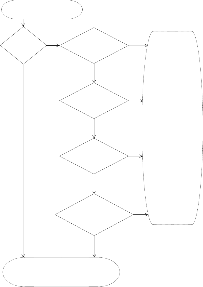
570 CHAPTER 26: ROGUE DETECTION AND COUNTERMEASURES
Figure 34 Rogue Detection Algorithm
MAP radio detects wireless packet.
No
Yes Yes
Source MAC in SSID in Permitted
Ignore List?
Device is not a threat.
SSID List?
Yes
OUI in Permitted
Vendor List?
No
Source MAC in
Attack List?
No
Generate an alarm.
Classify device as a rogue.
No
Yes
Issue countermeasures
(if enabled).
No
Rogue classification
Yes
algorithm deems the
device to be a rogue?
About Rogues and RF Detection 571
RF Detection Scans All radios continually scan for other RF transmitters. Radios perform
passive scans and active scans:
Passive scans — The radio listens for beacons and probe responses.
Active scans — The radio sends probe any requests (probe requests
with a null SSID name) to solicit probe responses from other access
points.
Passive scans are always enabled and cannot be disabled. Active scans are
enabled by default but can be disabled on a radio-profile basis.
Radios perform both types of scans on all channels allowed for the
country of operation. (This is the regulatory domain set by the set
system countrycode command.) 802.11b/g radios scan in the 2.4 GHz
to 2.4835 GHz spectrum. 802.11a radios scan in the 5.15 GHz to 5.85
GHz spectrum.
Both enabled radios and disabled radios perform these scans.
The active-scan algorithm is sensitive to high-priority (voice or video)
traffic or heavy data traffic. Active-scan scans for 30 msec once every
second, unless either of the following conditions is true:
High-priority traffic (voice or video) is present at 64 Kbps or higher. In
this case, active-scan scans for 30 msec every 60 seconds.
Heavy data traffic is present at 4 Mbps or higher. In this case,
active-scan scans for 30 msec every 5 seconds.
On a disabled radio, the radio is dedicated to rogue detection and scans
on each channel in round-robin fashion.
Dynamic Frequency Selection (DFS)
Some regulatory domains require conformance to ETSI document
EN 301 893. Section 4.6 of that document specifies requirements for
Dynamic Frequency Selection (DFS). These requirements apply to radios
operating in the 5 GHz band (802.11a radios).
In countries where Dynamic Frequency Selection (DFS) is required, MSS
performs the appropriate check for radar. If radar is detected on a
channel, the MAP radio stops performing active scans on that channel in
accordance with DFS. However, the radio continues to passively scan for
beacons from rogue devices.

572 CHAPTER 26: ROGUE DETECTION AND COUNTERMEASURES
When a MAP radio detects radar on a channel, the radio switches to
another channel and does not attempt to use the channel where the
radar was detected for 30 minutes. MSS also generates a message.
The RF Auto-tuning feature must be enabled. Otherwise MSS cannot
change the channel.
Countermeasures You can enable MSS to use countermeasures against rogues.
Countermeasures consist of packets that interfere with a client’s ability to
use the rogue.
Countermeasures are disabled by default. You can enable them on an
individual radio-profile basis. When you enable them, all devices of
interest that are not in the known devices list become viable targets for
countermeasures. Countermeasures can be enabled against all rogue and
interfering devices, against rogue devices only, or against devices explicitly
configured in the WX switch’s attack list. The Mobility Domain’s seed
switch automatically selects individual radios to send the countermeasure
packets.
Mobility Domain
Requirement
RF Detection requires the Mobility Domain to be completely up. If a
Mobility Domain is not fully operational (not all members are up), no new
RF Detection data is processed. Existing RF Detection information ages
out normally. Processing of RF Detection data is resumed only when all
members of the Mobility Domain are up. If a seed switch in the Mobility
Domain cannot resume full operation, you can restore the Mobility
Domain to full operation, and therefore resume RF Detection data
processing, by removing the inoperative switch from the member list on
the seed.

Summary of Rogue Detection Features 573
Summary of Rogue
Detection Features
Table 48 lists the rogue detection features in MSS.
Table 48 Rogue Detection Features
Rogue
Detection
Feature Description
Applies To
Third-Party
APs Clients
Classification MSS can classify third-party APs as
rogues or interfering devices. A
rogue is a third-party AP whose
MAC address MSS knows from the
wired side of the network. An
interfering device does not have a
MAC address known on the wired
side.
MSS can detect rogue clients, locate
their APs, and issue countermeasures
against the APs.
Yes Yes
Permitted
vendor list List of OUIs to allow on the network.
An OUI is the first three octets of a
MAC address and uniquely identifies
an AP’s or client’s vendor.
Yes No
Permitted SSID
list List of SSIDs allowed on the network.
MSS can issue countermeasures
against third-party APs sending
traffic for an SSID that is not on the
list.
Yes Yes
Client black list List of client or AP MAC addresses
that are not allowed on the wireless
network. MSS drops all packets from
these clients or APs.
Yes Yes
Attack list List of AP MAC addresses to attack.
MSS can issue countermeasures
against these APs whenever they are
detected on the network.
Yes No
Ignore list List of MAC addresses to ignore
during RF detection. MSS does not
classify devices on this list as rogues
or interfering devices, and does not
issue countermeasures against them.
Yes Yes

574 CHAPTER 26: ROGUE DETECTION AND COUNTERMEASURES
Configuring Rogue
Detection Lists
The following sections describe how to configure lists to specify the
devices that are allowed on the network and the devices that MSS should
attack with countermeasures.
(For information about how MSS uses the lists, see “Rogue Detection
Lists” on page 569.)
Configuring a
Permitted Vendor List
The permitted vendor list specifies the third-party AP or client vendors
that are allowed on the network. MSS does not list a device as a rogue or
interfering device if the device’s OUI is in the permitted vendor list.
By default, the permitted vendor list is empty and all vendors are allowed.
If you configure a permitted vendor list, MSS allows only the devices
whose OUIs are on the list. The permitted vendor list applies only to the
WX switch on which the list is configured. WX switches do not share
permitted vendor lists.
Countermeasures Packets sent by 3Com MAPs to
interfere with the operation of a
rogue or interfering device.
Countermeasures are configurable
on a radio-profile basis.
Yes Yes
Active scan Active scan sends probe any requests
(probes with a null SSID name) to
look for rogue APs.
Active scan is configurable on a
radio-profile basis.
Yes No
3Com MSP
signature Value in a MAP’s management
frames that identifies the MAP to
MSS. MAP signatures help prevent
spoofing of the MAP MAC address.
No No
Log messages
and traps Messages and traps for rogue
activity. Messages are described in
“IDS and DoS Alerts” on page 584.
Yes Yes
Table 48 Rogue Detection Features (continued)
Rogue
Detection
Feature Description
Applies To
Third-Party
APs Clients
Configuring Rogue Detection Lists 575
If you add a device that MSS has classified as a rogue to the permitted
vendor list, but not to the ignore list, MSS can still classify the device as a
rogue. Adding an entry to the permitted vendor list merely indicates that
the device is from an allowed vendor. However, to cause MSS to stop
classifying the device as a rogue, you must add the device’s MAC address
to the ignore list.
To add an entry to the permitted vendor list, use the following command:
set rfdetect vendor-list {client | ap} mac-addr
The following command adds an entry for clients whose MAC addresses
start with aa:bb:cc:
WX1200# set rfdetect vendor-list client aa:bb:cc:00:00:00
success: MAC aa:bb:cc:00:00:00 is now in client vendor-list.
The trailing 00:00:00 value is required.
To display the permitted vendor list, use the following command:
display rfdetect vendor-list
The following example shows the permitted vendor list on a switch:
WX1200# display rfdetect vendor-list
Total number of entries: 1
OUI Type
----------------- ------
aa:bb:cc:00:00:00 client
11:22:33:00:00:00 ap
To remove an entry from the permitted vendor list, use the following
command:
clear rfdetect vendor-list {client | ap} {mac-addr | all}
The following command removes client OUI aa:bb:cc:00:00:00 from the
permitted vendor list:
WX1200# clear rfdetect vendor-list client aa:bb:cc:00:00:00
success: aa:bb:cc:00:00:00 is no longer in client
vendor-list.
576 CHAPTER 26: ROGUE DETECTION AND COUNTERMEASURES
Configuring a
Permitted SSID List
The permitted SSID list specifies the SSIDs that are allowed on the
network. If MSS detects packets for an SSID that is not on the list, the AP
that sent the packets is classified as a rogue. MSS issues countermeasures
against the rogue if they are enabled.
By default, the permitted SSID list is empty and all SSIDs are allowed. If
you configure a permitted SSID list, MSS allows traffic only for the SSIDs
that are on the list. The permitted SSID list applies only to the WX switch
on which the list is configured. WX switches do not share permitted SSID
lists.
If you add a device that MSS has classified as a rogue to the permitted
SSID list, but not to the ignore list, MSS can still classify the device as a
rogue. Adding an entry to the permitted SSID list merely indicates that
the device is using an allowed SSID. However, to cause MSS to stop
classifying the device as a rogue, you must add the device’s MAC address
to the ignore list.
To add an SSID to the list, use the following command:
set rfdetect ssid-list ssid-name
The following command adds SSID mycorp to the list of permitted SSIDs:
WX4400# set rfdetect ssid-list mycorp
success: ssid mycorp is now in ssid-list.
To display the permitted SSID list, use the following command:
display rfdetect ssid-list
The following example shows the permitted SSID list on a WX switch:
WX1200# display rfdetect ssid-list
Total number of entries: 3
SSID
-----------------
mycorp
corporate
guest
To remove an SSID from the permitted SSID list, use the following
command:
clear rfdetect ssid-list ssid-name
Configuring Rogue Detection Lists 577
The following command clears SSID mycorp from the permitted SSID list:
WX1200# clear rfdetect ssid-list mycorp
success: mycorp is no longer in ssid-list.
Configuring a Client
Black List
The client black list specifies clients that are not allowed on the network.
MSS drops all packets from the clients on the black list.
By default, the client black list is empty. In addition to manually
configured entries, the list can contain entries added by MSS. MSS can
place a client in the black list due to an association, reassociation or
disassociation flood from the client.
The client black list applies only to the WX switch on which the list is
configured. WX switches do not share client black lists.
To add an entry to the list, use the following command:
set rfdetect black-list mac-addr
The following command adds client MAC address 11:22:33:44:55:66 to
the black list:
WX1200# set rfdetect black-list 11:22:33:44:55:66
success: MAC 11:22:33:44:55:66 is now blacklisted.
To display the client black list, use the following command:
display rfdetect black-list
The following example shows the client black list on WX switch:
WX1200# display rfdetect black-list
Total number of entries: 1
Blacklist MAC Type Port TTL
----------------- ----------------- ------- ---
11:22:33:44:55:66 configured - -
11:23:34:45:56:67 assoc req flood 3 25
To remove a MAC address from the client black list, use the following command:
clear rfdetect black-list mac-addr
The following command removes MAC address 11:22:33:44:55:66 from
the black list:
WX1200# clear rfdetect black-list 11:22:33:44:55:66
success: 11:22:33:44:55:66 is no longer blacklisted.

578 CHAPTER 26: ROGUE DETECTION AND COUNTERMEASURES
Configuring an
Attack List
The attack list specifies the MAC addresses of devices that MSS should
issue countermeasures against whenever the devices are detected on the
network. The attack list can contain the MAC addresses of APs and
clients.
By default, the attack list is empty. The attack list applies only to the WX
switch on which the list is configured. WX switches do not share attack
lists.
When on-demand countermeasures are enabled, only those devices
configured in the attack list are subject to countermeasures. In this case,
devices found to be rogues by other means, such as policy violations or by
determining that the device is providing connectivity to the wired
network, are not attacked.
If you are using on-demand countermeasures in a Mobility Domain, you
should synchronize the attack lists on all the WX switches in the Mobility
Domain. See “Using On-Demand Countermeasures in a Mobility Domain”
on page 581.
To add an entry to the attack list, use the following command:
set rfdetect attack-list mac-addr
The following command adds MAC address aa:bb:cc:44:55:66 to the
attack list:
WX4400# set rfdetect attack-list 11:22:33:44:55:66
success: MAC 11:22:33:44:55:66 is now in attacklist.
To display the attack list, use the following command:
display rfdetect attack-list
The following example shows the attack list on a switch:
WX4400# display rfdetect attack-list
Total number of entries: 1
Attacklist MAC Port/Radio/Chan RSSI SSID
----------------- ----------------- ------ ------------
11:22:33:44:55:66 dap 2/1/11 -53 rogue-ssid
To remove a MAC address from the attack list, use the following
command:
clear rfdetect attack-list mac-addr

Configuring Rogue Detection Lists 579
The following command clears MAC address 11:22:33:44:55:66 from the
attack list:
WX4400# clear rfdetect attack-list 11:22:33:44:55:66
success: 11:22:33:44:55:66 is no longer in attacklist.
Configuring an
Ignore List
By default, when countermeasures are enabled, MSS considers any
non-3Com transmitter to be a rogue device and can send
countermeasures to prevent clients from using that device. To prevent
MSS from sending countermeasures against a friendly device, add the
device to the known devices list:
If you add a device that MSS has classified as a rogue to the permitted
vendor list or permitted SSID list, but not to the ignore list, MSS can still
classify the device as a rogue. Adding an entry to the permitted vendor
list or permitted SSID list merely indicates that the device is from an
allowed manufacturer or is using an allowed SSID. However, to cause
MSS to stop classifying the device as a rogue, you must add the device’s
MAC address to the ignore list.
To add a device to the ignore list, use the following command:
set rfdetect ignore mac-addr
The mac-addr is the BSSID of the device you want to ignore.
If you try to initiate countermeasures against a device on the ignore list,
the ignore list takes precedence and MSS does not issue the
countermeasures. Countermeasures apply only to rogue devices.
To ignore BSSID aa:bb:cc:11:22:33 during all RF scans, type the following
command:
WX1200#set rfdetect ignore aa:bb:cc:11:22:33
success: MAC aa:bb:cc:11:22:33 is now ignored.
To remove a BSSID from the ignore list, use the following command:
clear rfdetect ignore mac-addr
To display the ignore list, use the following command:
display rfdetect ignore

580 CHAPTER 26: ROGUE DETECTION AND COUNTERMEASURES
The following command displays an ignore list containing two BSSIDs:
WX4400# display rfdetect ignore
Total number of entries: 2
Ignore MAC
-----------------
aa:bb:cc:11:22:33
aa:bb:cc:44:55:66
Enabling
Countermeasures
Countermeasures are disabled by default. You can enable them on an
individual radio profile basis. To enable countermeasures on a radio
profile, use the following command:
set radio-profile name countermeasures {all | rogue |
configured | none}
The all option enables or disables countermeasures for rogues and for
interfering devices. This option is equivalent to the scope of rogue
detection in MSS Version 3.x. The rogue option enables or disables
countermeasures for rogues only.
The configured option causes radios to attack only devices specified in
the attack list on the WX switch (on-demand countermeasures). When
this option is used, devices found to be rogues by other means, such as
policy violations or by determining that the device is providing
connectivity to the wired network, are not attacked.
The none option disables countermeasures for this radio profile.
The following command enables countermeasures in radio profile
radprof3 for rogues only:
WX4400# set radio-profile radprof3 countermeasures rogue
success: change accepted.
The following command causes radios managed by radio profile radprof3
to issue countermeasures against devices in the WX switch’s attack list:
WX4400# set radio-profile radprof3 countermeasures configured
success: change accepted.
To disable countermeasures on a radio profile, use the following
command:
clear radio-profile name countermeasures
Enabling Countermeasures 581
The following command disables countermeasures in radio profile
radprof3:
WX4400# clear radio-profile radprof3 countermeasures
success: change accepted.
Using On-Demand
Countermeasures in a
Mobility Domain
If you are using on-demand countermeasures in a Mobility Domain, you
should enable the feature and synchronize the attack lists on all the WX
switches in the Mobility Domain. This ensures a WX switch attacks
devices in its attack list, rather than devices that may be specified in the
attack lists of other WX switches in the Mobility Domain, which could
produce unexpected results.
For example, in a Mobility Domain consisting of three WX switches, if WX
switch A has an attack list consisting of MAC address 1, and WX switch B
has an attack list consisting of MAC address 2, then WX switch C (the
seed for the Mobility Domain) might determine that the optimal radio to
attack MAC address 2 is attached to WX switch A.
This would mean that MAC address 2 would be attacked from WX switch
A, even though MAC address 2 does not reside in WX switch A’s attack
list. In addition, if the MAP attached to WX switch A is busy attacking
MAC address 2, then MAC address 1 might not be attacked at all if it
comes on the network.
By making the attack lists identical on all of the WX switches in the
Mobility Domain when you enable on-demand countermeasures, it
ensures that a WX switch always attacks MAC addresses that reside in its
attack list. Note that WX switches do not share attack lists automatically,
so you must manually synchronize the attack lists on the WX switches in
the Mobility Domain.
582 CHAPTER 26: ROGUE DETECTION AND COUNTERMEASURES
Disabling or
Reenabling Active
Scan
When active scanning is enabled, the MAP radios managed by the switch
look for rogue devices by sending probe any frames (probes with a null
SSID name), to solicit probe responses from other APs.
Active scan is enabled by default. You can disable or reenable the feature
on an individual radio profile basis. To disable or reenable active scan on a
radio profile, use the following command:
set radio-profile name active-scan {enable | disable}
The following command disables active scan in radio profile radprof3:
WX1200# set radio-profile radprof3 active-scan disable
success: change accepted.
Enabling MAP
Signatures
A MAP signature is a set of bits in a management frame sent by a MAP
that identifies that MAP to MSS. If someone attempts to spoof
management packets from a 3Com MAP, MSS can detect the spoof
attempt.
MAP signatures are disabled by default. To enable or disable them, use
the following command:
set rfdetect signature {enable | disable}
The command applies only to MAPs managed by the WX switch on
which you enter the command. To enable signatures on all MAPs in a
Mobility Domain, enter the command on each WX switch in the Mobility
Domain.
You must use the same MAP signature setting (enabled or disabled) on all
WX switches in a Mobility Domain.
Enabling MAP Signatures 583
Creating an
Encrypted
RF Fingerprint Key as
a MAP Signature
To create an encrypted RF fingerprint key to use as a signature for a MAP,
use the following command:
set rfdetect signature key encrypted <key_value>
For example:
WXR100_desk# set rfdetect ?
attack-list Add a device to attack-list
black-list black-list specific device
ignore set rfdetect transmitter mac to be ignored
log set rfdetect log messages enable/disable
signature set rfdetect signature operations
ssid-list add an ssid to allowed ssid list
vendor-list add a device to vendor-list
WXR100_desk# set rfdetect signature ?
<enable> enable or disable AP mgmt-frame signatures
key set rfdetect signature key operations
WXR100_desk# set rfdetect signature key ?
<key_value> RF key fingerprint (16 bytes separated by
colons) on the AP
encrypted set the signature key used in management frames
WXR100_desk# set rfdetect signature key encrypted ?
<key_value> RF encrypted key fingerprint
WXR100_desk# set rfdetect signature key encrypted
584 CHAPTER 26: ROGUE DETECTION AND COUNTERMEASURES
Disabling or
Reenabling Logging
of Rogues
By default, a WX switch generates a log message when a rogue is
detected or disappears. To disable or reenable the log messages, use the
following command:
set rfdetect log {enable | disable}
To display log messages on a switch, use the following command:
display log buffer
(This command has optional parameters. For complete syntax
information, see the Wireless LAN Switch and Controller Command
Reference.)
Enabling Rogue and
Countermeasures
Notifications
By default, all SNMP notifications (informs or traps) are disabled. To
enable or disable notifications for rogue detection, Intrusion Detection
System (IDS), and Denial of Service (DoS) protection, configure a
notification profile that sends all the notification types for these features.
(For syntax information and an example, see “Configuring a Notification
Profile” on page 144.)
IDS and DoS Alerts MSS can detect illegitimate network access attempts and attempts to
disrupt network service. In response, MSS generates messages and SNMP
notifications. The following sections describe the types of attacks and
security risks that MSS can detect.
For examples of the log messages that MSS generates when DoS attacks
or other security risks are detected, see “IDS Log Message Examples” on
page 587.
For information about the notifications, see “Configuring a Notification
Profile” on page 144.
To detect DoS attacks, active scan must be enabled. (See “Disabling or
Reenabling Active Scan” on page 582.)
IDS and DoS Alerts 585
Flood Attacks A flood attack is a type of Denial of Service attack. During a flood attack,
a rogue wireless device attempts to overwhelm the resources of other
wireless devices by continuously injecting management frames into the
air. For example, a rogue client can repeatedly send association requests
to try to overwhelm APs that receive the requests.
The threshold for triggering a flood message is 100 frames of the same
type from the same MAC address, within a one-second period. If MSS
detects more than 100 of the same type of wireless frame within one
second, MSS generates a log message. The message indicates the frame
type, the MAC address of the sender, the listener (MAP and radio),
channel number, and RSSI.
DoS Attacks When active scan is enabled on MAPs, MSS can detect the following
types of DoS attacks:
RF Jamming—The goal of an RF jamming attack is to take down an
entire WLAN by overwhelming the radio environment with
high-power noise. A symptom of an RF jamming attack is excessive
interference. If a MAP radio detects excessive interference on a
channel, and RF Auto-Tuning is enabled, MSS changes the radio to a
different channel.
Deauthenticate frames—Spoofed deauthenticate frames form the
basis for most DoS attacks, and are the basis for other types of attacks
including man-in-the-middle attacks. The source MAC address is
spoofed so that clients think the packet is coming from a legitimate
AP. If a MAP detects a packet with its own source MAC address, the
MAP knows that the packet was spoofed.
Broadcast deauthenticate frames—Similar to the spoofed
deauthenticate frame attack above, a broadcast deauthenticate frame
attack generates spoofed deauthenticate frames, with a broadcast
destination address instead of the address of a specific client. The
intent of the attack is to disconnect all stations attached to an AP.
Disassociation frames—A disassociation frame from an AP instructs
the client to end its association with the AP. The intent of this attack is
to disconnect clients from the AP.
Null probe responses—A client’s probe request frame is answered by
a probe response containing a null SSID. Some NIC cards lock up upon
receiving such a probe response.

586 CHAPTER 26: ROGUE DETECTION AND COUNTERMEASURES
Decrypt errors—An excessive number of decrypt errors can indicate
that multiple clients are using the same MAC address. A device’s MAC
address is supposed to be unique. Multiple instances of the same
address can indicate that a rogue device is pretending to be a
legitimate device by spoofing its MAC address.
Fake AP—A rogue device sends beacon frames for randomly
generated SSIDs or BSSIDs. This type of attack can cause clients to
become confused by the presence of so many SSIDs and BSSIDs, and
thus interferes with the clients’ ability to connect to valid APs. This
type of attack can also interfere with RF Auto-Tuning when a MAP is
trying to adjust to its RF neighborhood.
SSID masquerade—A rogue device pretends to be a legitimate AP by
sending beacon frames for a valid SSID serviced by APs in your
network. Data from clients that associate with the rogue device can
be accessed by the hacker controlling the rogue device.
Spoofed AP—A rogue device pretends to be a 3Com MAP by sending
packets with the source MAC address of the 3Com MAP. Data from
clients that associate with the rogue device can be accessed by the
hacker controlling the rogue device.
MSS detects a spoofed AP attack based on the fingerprint of the spoofed
MAP. Packets from the real MAP have the correct signature, while
spoofed packets lack the signature. (See “Enabling MAP Signatures” on
page 582.)
Netstumbler and
Wellenreiter
Applications
Netstumbler and Wellenreiter are widely available applications that
hackers can use to gather information about the APs in your network,
including location, manufacturer, and encryption settings.
Wireless Bridge A wireless bridge can extend a wireless network outside the desired area.
For example, someone can place a wireless bridge near an exterior wall to
extend wireless coverage out into the parking lot, where a hacker could
then gain access to the network.
Ad-Hoc Network An ad-hoc network is established directly among wireless clients and
does not use the infrastructure network (a network using an AP). An
ad-hoc network might not be an intentionally malicious attack on the
network, but it does steal bandwidth from your infrastructure users.

IDS and DoS Alerts 587
Weak WEP Key Used
by Client
A weak initialization vector (IV) makes a WEP key easier to hack. MSS
alerts you regarding clients who are using weak WEP IVs so that you can
strengthen the encryption on these clients or replace the clients.
Disallowed Devices or
SSIDs
You can configure the following types of lists to explicitly allow specific
devices or SSIDs:
Permitted SSID list—MSS generates a message if an SSID that is not on
the list is detected.
Permitted vendor list—MSS generates a message if an AP or wireless
client with an OUI that is not on the list is detected.
Client black list—MSS prevents clients on the list from accessing the
network through a WX switch. If the client is placed on the black list
dynamically by MSS due to an association, reassociation or
disassociation flood, MSS generates a log message.
By default, these lists are empty and all SSIDs, vendors, and clients are
allowed. For more information, see “Summary of Rogue Detection
Features” on page 573.
Displaying Statistics
Counters
To display IDS and DoS statistics counters, use the display rfdetect
counters commands. (See “Displaying Statistics Counters” on
page 587.)
IDS Log Message
Examples
Table 49 shows examples of the log messages generated by IDS.
Table 49 IDS and DoS Log Messages
Message Type Example Log Message
Probe message flood Client aa:bb:cc:dd:ee:ff is sending probe message flood.
Seen by AP on port 2, radio 1 on channel 11 with RSSI
-53.
Authentication
message flood Client aa:bb:cc:dd:ee:ff is sending authentication message
flood.
Seen by AP on port 2, radio 1 on channel 11 with RSSI
-53.
Null data message
flood Client aa:bb:cc:dd:ee:ff is sending null data message
flood.
Seen by AP on port 2, radio 1 on channel 11 with
RSSI -53.

588 CHAPTER 26: ROGUE DETECTION AND COUNTERMEASURES
Management frame 6
flood Client aa:bb:cc:dd:ee:ff is sending rsvd mgmt frame 6
message flood.
Seen by AP on port 2, radio 1 on channel 11 with RSSI
-53.
Management frame 7
flood Client aa:bb:cc:dd:ee:ff is sending rsvd mgmt frame 7
message flood.
Seen by AP on port 2, radio 1 on channel 11 with RSSI
-53.
Management frame D
flood Client aa:bb:cc:dd:ee:ff is sending rsvd mgmt frame D
message flood.
Seen by AP on port 2, radio 1 on channel 11 with RSSI
-53.
Management frame E
flood Client aa:bb:cc:dd:ee:ff is sending rsvd mgmt frame E
message flood.
Seen by AP on port 2, radio 1 on channel 11 with RSSI
-53.
Management frame F
flood Client aa:bb:cc:dd:ee:ff is sending rsvd mgmt frame F
message flood.
Seen by AP on port 2, radio 1 on channel 11 with RSSI
-53.
Associate request
flood Client aa:bb:cc:dd:ee:ff is sending associate request flood
on port 2
Reassociate request
flood Client aa:bb:cc:dd:ee:ff is sending re-associate request
flood on port 2
Disassociate request
flood Client aa:bb:cc:dd:ee:ff is sending disassociate request
flood on port 2
Weak WEP
initialization vector
(IV)
Client aa:bb:cc:dd:ee:ff is using weak wep initialization
vector.
Seen by AP on port 2, radio 1 on channel 11 with RSSI
-53.
Decrypt errors Client aa:bb:cc:dd:ee:ff is sending packets with decrypt
errors.
Seen by AP on port 2, radio 1 on channel 11 with RSSI
-53.
Spoofed
deauthentication
frames
Deauthentication frame from AP aa:bb:cc:dd:ee:ff is being
spoofed.
Seen by AP on port 2, radio 1 on channel 11 with RSSI
-53.
Table 49 IDS and DoS Log Messages (continued)
Message Type Example Log Message

IDS and DoS Alerts 589
Spoofed
disassociation frames Disassociation frame from AP aa:bb:cc:dd:ee:ff is being
spoofed.
Seen by AP on port 2, radio 1 on channel 11 with RSSI
-53.
Null probe responses AP aa:bb:cc:dd:ee:ff is sending null probe responses.
Seen by AP on port 2, radio 1 on channel 11 with RSSI
-53.
Broadcast
deauthentications AP aa:bb:cc:dd:ee:ff is sending broadcast
deauthentications.
Seen by AP on port 2, radio 1 on channel 11 with RSSI
-53.
Fake AP SSID (when
source MAC address
is known)
FakeAP SSID attack detected from aa:bb:cc:dd:ee:ff.
Seen by AP on port 2, radio 1 on channel 11 with RSSI -53
SSID myssid.
Fake AP SSID (when
source MAC address
is not known)
FakeAP BSSID attack detected.
Seen by AP on port 2, radio 1 on channel 11 with RSSI -53
SSID myssid.
Spoofed SSID AP Mac aa:bb:cc:dd:ee:ff(ssid myssid) is masquerading our
ssid used by aa:bb:cc:dd:ee:fd.
Detected by listener aa:bb:cc:dd:ee:fc(port 2, radio 1),
channel 11 with RSSI -53.
Wireless bridge
detected Wireless bridge detected with address aa:bb:cc:dd:ee:ff.
Seen by AP on port 2, radio 1 on channel 11 with RSSI -53
SSID myssid.
Netstumbler detected Netstumbler detected from aa:bb:cc:dd:ee:ff.
Seen by AP on port 2, radio 1 on channel 11 with RSSI -53
SSID myssid.
Wellenreiter detected Wellenreiter detected from aa:bb:cc:dd:ee:ff.
Seen by AP on port 2, radio 1 on channel 11 with RSSI -53
SSID myssid.
Ad-hoc client frame
detected Adhoc client frame detected from aa:bb:cc:dd:ee:ff.
Seen by AP on port 2, radio 1 on channel 11 with RSSI -53
SSID myssid.
Table 49 IDS and DoS Log Messages (continued)
Message Type Example Log Message

590 CHAPTER 26: ROGUE DETECTION AND COUNTERMEASURES
Displaying RF
Detection
Information
You can use the CLI commands listed in Table 50 to display rogue
detection information.
Spoofed AP AP Mac aa:bb:cc:dd:ee:ff(ssid myssid) is being spoofed.
Received fingerprint 1122343 does not match our
fingerprint 123344.
Detected by listener aa:bb:cc:dd:ee:fd(port 2, radio 1),
channel 11 with RSSI -53.
Disallowed SSID
detected AP Mac aa:bb:cc:dd:ee:ff(ssid myssid) is not part of
ssid-list.
Detected by listener aa:bb:cc:dd:ee:fd(port 2, radio 1),
channel 11 with RSSI -53.
AP from disallowed
vendor detected AP Mac aa:bb:cc:dd:ee:ff(ssid myssid) is not part of
vendor-list.
Detected by listener aa:bb:cc:dd:ee:fd(port 2, radio 1),
channel 11 with RSSI -53.
Client from
disallowed vendor
detected
Client Mac aa:bb:cc:dd:ee:ff is not part of vendor-list.
Detected by listener aa:bb:cc:dd:ee:fd(port 2, radio 1),
channel 11 with RSSI -53.
Interfering client seen
on wired network Client Mac aa:bb:cc:dd:ee:ff is seen on the wired network
by WX 10.1.1.1 on port 3 vlan 2 tag 1. Detected by
listener aa:bb:cc:dd:ee:fd(port 2, radio 1), channel 11 with
RSSI -53.
Table 49 IDS and DoS Log Messages (continued)
Message Type Example Log Message
Table 50 Rogue Detection Display Commands
Command Description
display rfdetect clients
[mac mac-addr]Displays all wireless clients detected on the
air.
display rfdetect counters Displays statistics for rogue and Intrusion
Detection System (IDS) activity detected by
the MAPs managed by a WX switch.
display rfdetect mobility-domain
[ssid ssid-name | bssid mac-addr]Displays information about rogues detected
in a Mobility Domain.
This command is valid only on the Mobility
Domain’s seed switch.

Displaying RF Detection Information 591
(For information about the fields in the output, see the Wireless LAN
Switch and Controller Command Reference.)
display rfdetect data Displays information about all BSSIDs
detected on the air, and labels those that
are from rogues or interfering devices.
This command is valid on any switch in the
Mobility Domain.
display rfdetect visible mac-addr
display rfdetect visible
ap map-num [radio {1|2}]
Displays the BSSIDs detected by a specific
3Com radio.
display rfdetect countermeasures Displays the current status of
countermeasures against rogues in the
Mobility Domain.
This command is valid only on the Mobility
Domain seed.
display rfdetect vendor-list Displays the list of OUIs that are allowed on
the network. An OUI identifies a piece of
networking equipment’s vendor. (See
“Configuring a Permitted Vendor List” on
page 574.)
display rfdetect ssid-list Displays the list of SSIDs that are allowed on
the network. (See “Configuring a Permitted
SSID List” on page 576.)
display rfdetect black-list Displays the list of wireless clients that are
not allowed on the network. (See
“Configuring a Client Black List” on
page 577.)
display rfdetect attack-list Displays the list of wireless devices that you
want MAPs to attack with
countermeasures. (See “Configuring an
Attack List” on page 578.)
display rfdetect ignore Displays the BSSIDs of third-party devices
that MSS ignores during RF detection scans.
(See “Configuring an Ignore List” on
page 579.)
Table 50 Rogue Detection Display Commands (continued)
Command Description
592 CHAPTER 26: ROGUE DETECTION AND COUNTERMEASURES
Displaying Rogue
Clients
To display the wireless clients detected by a WX switch, use the following
command:
display rfdetect clients [mac mac-addr]
The following command shows information about all wireless clients
detected by a WX switch’s MAPs:
WX# display rfdetect clients
Total number of entries: 58
Client MAC Client AP MAC AP AP/Radio NoL Type Last
Vendor Vendor /Channel seen
----------------- ------- ----------------- ------- ---------- --- ----- ----
00:04:23:53:4c:39 Intel Unknown 7/1/3 1 intfr 56
00:05:4e:4f:fa:1d Unknown 00:0b:0e:23:1e:c1 3Com 7/2/44 2 intfr 103
00:05:5d:79:ce:03 D-Link Unknown 7/1/10 2 intfr 151
00:05:5d:79:ce:04 D-Link Unknown 7/1/9 1 intfr 77
00:05:5d:7e:96:a1 D-Link Unknown 7/2/52 1 intfr 6
00:05:5d:7e:96:ce D-Link Unknown 7/2/48 2 intfr 70
00:05:5d:97:97:82 D-Link Unknown 7/2/52 1 intfr 812
00:06:25:13:07:5f Linksys Unknown 7/1/6 1 intfr 54
00:09:5b:66:ec:1b Netgear Unknown 7/2/64 2 intfr 28
00:0b:0e:0c:10:ff 3Com 00:0b:0e:30:83:41 3Com 7/2/161 1 intfr 205
00:0b:0e:17:bb:3f 3Com 00:0b:0e:31:55:41 3Com 7/2/153 1 intfr 15
The following command displays more details about a specific client:
WX1200# display rfdetect clients mac 00:0c:41:63:fd:6d
Client Mac Address: 00:0c:41:63:fd:6d, Vendor: Linksys
Port: dap 1, Radio: 1, Channel: 11, RSSI: -82, Rate: 2, Last Seen (secs ago): 84
Bssid: 00:0b:0e:01:02:00, Vendor: 3Com, Type: intfr, Dst: ff:ff:ff:ff:ff:ff
Last Rogue Status Check (secs ago): 3
The first line lists information for the client. The other lines list
information about the most recent 802.11 packet detected from the
client.
Displaying RF Detection Information 593
Displaying Rogue
Detection Counters
To display rogue detection statistics counters, use the following
command:
display rfdetect counters
The command shows counters for rogue activity detected by the WX
switch on which you enter the command.
WX1200# display rfdetect counters
Type Current Total
-------------------------------------------------- ------------ ------------
Rogue access points 0 0
Interfering access points 139 1116
Rogue 802.11 clients 0 0
Interfering 802.11 clients 4 347
802.11 adhoc clients 0 1
Unknown 802.11 clients 20 965
Interfering 802.11 clients seen on wired network 0 0
802.11 probe request flood 0 0
802.11 authentication flood 0 0
802.11 null data flood 0 0
802.11 mgmt type 6 flood 0 0
802.11 mgmt type 7 flood 0 0
802.11 mgmt type d flood 0 0
802.11 mgmt type e flood 0 0
802.11 mgmt type f flood 0 0
802.11 association flood 0 0
802.11 reassociation flood 0 0
802.11 disassociation flood 0 0
Weak wep initialization vectors 0 0
Spoofed access point mac-address attacks 0 0
Spoofed client mac-address attacks 0 0
Ssid masquerade attacks 1 12
Spoofed deauthentication attacks 0 0
Spoofed disassociation attacks 0 0
Null probe responses 626 11380
Broadcast deauthentications 0 0
FakeAP ssid attacks 0 0
FakeAP bssid attacks 0 0
Netstumbler clients 0 0
Wellenreiter clients 0 0
Active scans 1796 4383
Wireless bridge frames 196 196
Adhoc client frames 8 0
Access points present in attack-list 0 0

594 CHAPTER 26: ROGUE DETECTION AND COUNTERMEASURES
Access points not present in ssid-list 0 0
Access points not present in vendor-list 0 0
Clients not present in vendor-list 0 0
Clients added to automatic black-list 0 0
MSS generates log messages for most of these statistics. See “IDS and
DoS Alerts” on page 584.
Displaying SSID or
BSSID Information for
a Mobility Domain
To display SSID or BSSID information for an entire Mobility Domain, use
the following command on the seed switch:
display rfdetect mobility-domain [ssid ssid-name | bssid
mac-addr]
The following command displays summary information for all SSIDs and
BSSIDs detected in the Mobility Domain:
WX1200# display rfdetect mobility-domain
Total number of entries: 194
Flags: i = infrastructure, a = ad-hoc, u = unresolved
c = CCMP, t = TKIP, 1 = 104-bit WEP, 4 = 40-bit WEP, w = WEP(non-WPA)
BSSID Vendor Type Flags SSID
----------------- ------------ ----- ------ --------------------------------
00:07:50:d5:cc:91 Cisco intfr i----w r27-cisco1200-2
00:07:50:d5:dc:78 Cisco intfr i----w r116-cisco1200-2
00:09:b7:7b:8a:54 Cisco intfr i-----
00:0a:5e:4b:4a:c0 3Com intfr i----- public
00:0a:5e:4b:4a:c2 3Com intfr i----w 3Comwlan
00:0a:5e:4b:4a:c4 3Com intfr ic---- 3Com-ccmp
00:0a:5e:4b:4a:c6 3Com intfr i----w 3Com-tkip
00:0a:5e:4b:4a:c8 3Com intfr i----w 3Com-voip
00:0a:5e:4b:4a:ca 3Com intfr i----- 3Com-webaaa
...
The lines in this display are compiled from data from multiple listeners
(MAP radios). If an item has the value unresolved, not all listeners agree
on the value for that item. Generally, an unresolved state occurs only
when a MAP or a Mobility Domain is still coming up, and lasts only
briefly.
The following command displays detailed information for rogues using
SSID 3Com-webaaa.
WX1200# display rfdetect mobility-domain ssid 3Com-webaaa
BSSID: 00:0a:5e:4b:4a:ca Vendor: 3Com SSID: 3Com-webaaa
Type: intfr Adhoc: no Crypto-types: clear
Displaying RF Detection Information 595
WX-IPaddress: 10.8.121.102 Port/Radio/Ch: 3/1/11 Mac: 00:0b:0e:00:0a:6a
Device-type: interfering Adhoc: no Crypto-types: clear
RSSI: -85 SSID: 3Com-webaaa
BSSID: 00:0b:0e:00:7a:8a Vendor: 3Com SSID: 3Com-webaaa
Type: intfr Adhoc: no Crypto-types: clear
WX1200-IPaddress: 10.8.121.102 Port/Radio/Ch: 3/1/1 Mac: 00:0b:0e:00:0a:6a
Device-type: interfering Adhoc: no Crypto-types: clear
RSSI: -75 SSID: 3Com-webaaa
WX1200-IPaddress: 10.3.8.103 Port/Radio/Ch: dap 1/1/1 Mac: 00:0b:0e:76:56:82
Device-type: interfering Adhoc: no Crypto-types: clear
RSSI: -76 SSID: 3Com-webaaa
Two types of information are shown. The lines that are not indented
show the BSSID, vendor, and information about the SSID. The indented
lines that follow this information indicate the listeners (MAP radios) that
detected the SSID. Each set of indented lines is for a separate MAP
listener.
In this example, two BSSIDs are mapped to the SSID. Separate sets of
information are shown for each of the BSSIDs, and information about the
listeners for each BSSID is shown.
The following command displays detailed information for a BSSID.
WX1200# display rfdetect mobility-domain bssid 00:0b:0e:00:04:d1
BSSID: 00:0b:0e:00:04:d1 Vendor: Cisco SSID: notmycorp
Type: rogue Adhoc: no Crypto-types: clear
WX1200-IPaddress: 10.8.121.102 Port/Radio/Ch: 3/2/56 Mac: 00:0b:0e:00:0a:6b
Device-type: rogue Adhoc: no Crypto-types: clear
RSSI: -72 SSID: notmycorp
WX1200-IPaddress: 10.3.8.103 Port/Radio/Ch: dap 1/1/157 Mac: 00:0b:0e:76:56:82
Device-type: rogue Adhoc: no Crypto-types: clear
RSSI: -72 SSID: notmycorp
596 CHAPTER 26: ROGUE DETECTION AND COUNTERMEASURES
Displaying RF Detect
Data
To display information about the APs detected by an individual WX
switch, use the following command:
display rfdetect data
You can enter this command on any switch in the Mobility Domain.
WX1200# display rfdetect data
Total number of entries: 197
Flags: i = infrastructure, a = ad-hoc
c = CCMP, t = TKIP, 1 = 104-bit WEP, 4 = 40-bit WEP, w = WEP(non-WPA)
BSSID Vendor Type Port/Radio/Ch Flags RSSI Age SSID
----------------- ------- ----- ------------- ------ ---- --- -----------------
00:07:50:d5:cc:91 Cisco intfr 3/1/6 i----w -61 6 r27-cisco1200-2
00:07:50:d5:dc:78 Cisco intfr 3/1/6 i----w -82 6 r116-cisco1200-2
00:09:b7:7b:8a:54 Cisco intfr 3/1/2 i----- -57 6
00:0a:5e:4b:4a:c0 3Com intfr 3/1/11 i----- -57 6 public
00:0a:5e:4b:4a:c2 3Com intfr 3/1/11 i-t1-- -86 6 3Comwlan
00:0a:5e:4b:4a:c4 3Com intfr 3/1/11 ic---- -85 6 3Com-ccmp
00:0a:5e:4b:4a:c6 3Com intfr 3/1/11 i-t--- -85 6 3Com-tkip
00:0a:5e:4b:4a:c8 3Com intfr 3/1/11 i----w -83 6 3Com-voip
00:0a:5e:4b:4a:ca 3Com intfr 3/1/11 i----- -85 6 3Com-webaaa
...
Displaying the APs
Detected by MAP
Radio
To display the APs detected by a MAP radio, use any of the following
commands:
display rfdetect visible mac-addr
display rfdetect visible ap map-num [radio {1|2}]
display rfdetect visible dap dap-num [radio {1|2}]
To following command displays information about the rogues detected
by radio 1 on MAP port 3:
WX1200# display rfdetect visible ap 3 radio 1
Total number of entries: 104
Flags: i = infrastructure, a = ad-hoc
c = CCMP, t = TKIP, 1 = 104-bit WEP, 4 = 40-bit WEP, w = WEP(non-WPA)
Transmit MAC Vendor Type Ch RSSI Flags SSID
----------------- ------- ----- --- ---- ------ --------------------------------
00:07:50:d5:cc:91 Cisco intfr 6 -60 i----w r27-cisco1200-2
00:07:50:d5:dc:78 Cisco intfr 6 -82 i----w r116-cisco1200-2
00:09:b7:7b:8a:54 Cisco intfr 2 -54 i-----
00:0a:5e:4b:4a:c0 3Com intfr 11 -57 i----- public
00:0a:5e:4b:4a:c2 3Com intfr 11 -86 i-t1-- 3Comwlan
00:0a:5e:4b:4a:c4 3Com intfr 11 -85 ic---- 3Com-ccmp
Displaying RF Detection Information 597
00:0a:5e:4b:4a:c6 3Com intfr 11 -85 i-t--- 3Com-tkip
00:0a:5e:4b:4a:c8 3Com intfr 11 -83 i----w 3Com-voip
00:0a:5e:4b:4a:ca 3Com intfr 11 -85 i----- 3Com-webaaa
...
Displaying
Countermeasures
Information
To display the current status of countermeasures against rogues in the
Mobility Domain, use the following command:
display rfdetect countermeasures
This command is valid only on the Mobility Domain’s seed switch.
WX# display rfdetect countermeasures
Total number of entries: 190
Rogue MAC Type Countermeasures WX-IPaddr AP/Radio
Radio Mac /Channel
----------------- ----- ------------------ --------------- -------------
00:0b:0e:00:71:c0 intfr 00:0b:0e:44:55:66 10.1.1.23 4/1/6
00:0b:0e:03:00:80 rogue 00:0b:0e:11:22:33 10.1.1.23 2/1/11
598 CHAPTER 26: ROGUE DETECTION AND COUNTERMEASURES

27 MANAGING SYSTEM FILES
A Wireless Switch (WX) contains nonvolatile storage. MSS allows you to
manage the files in nonvolatile storage. In addition, you can copy files
between the WX switch and a TFTP server on the network.
About System Files Generally, a WX switch’s nonvolatile storage contains the following types
of files:
System image files — The operating system software for the WX
switch and its attached MAPs
Configuration files — CLI commands that configure the WX switch
and its attached MAPs
System log files — Files containing log entries generated by MSS.
When you power on or reset the WX switch or reboot the software, the
switch loads a designated system image, then loads configuration
information from a designated configuration file.
A WX switch can also contain temporary files with trace information used
for troubleshooting. Temporary files are not stored in nonvolatile memory,
but are listed when you display a directory of the files on the switch.
Displaying Software
Version Information
To display the software, firmware, and hardware versions, use the
following command:
display version [details]
The details option displays hardware and software information about the
MAPs configured on the WX switch.
600 CHAPTER 27: MANAGING SYSTEM FILES
To display version information for a WX switch, type the following
command:
WX# display version
Mobility System Software, Version: 6.0.0.2 REL
Copyright (c) 2002 - 2006 3Com Corporation. All rights
reserved.
Build Information: (build#0) REL_6_0_0_branch 2006-10-06 23:46:00
Model: WX-20
Hardware
Mainboard: version 24 ; revision 3 ; FPGA version 24
PoE board: version 1 ; FPGA version 6
Serial number 0321300013
Flash: 6.1.0.5 - md0a
Kernel: 3.0.0#14: Sat Oct 7 00:03:52 PDT 2006
BootLoader: 6.0 / 6.0.6
To also display MAP information, type the following command:
WX# display version details
Mobility System Software, Version: 6.0.0.2 REL
Copyright (c) 2002 - 2006 3Com Corporation. All rights
reserved.
Build Information: (build#0) REL_6_0_0_branch 2006-10-06 23:46:00
Label: REL_6.0.0.2.0_100606
Build Suffix: -d-O1
Model: WX-20
Hardware
Mainboard: version 24 ; revision 3 ; FPGA version 24
CPU Model: 750 (Revision 3.1)
PoE board: version 1 ; FPGA version 6
Serial number 0321300013
Flash: 6.1.0.5 - md0a
Kernel: 3.0.0#14: Sat Oct 7 00:03:52 PDT 2006
BootLoader: 6.0 / 6.0.6
AP AP Model Serial # Versions
----- ---------- ------------ ------------------------
7 MP-252 0333703050 H/W : A3
F/W1 : 5.6
F/W2 : 5.6
S/W : 6.0.0.2.0_100606_2346_
BOOT S/W : 6.0.0.2.0_100606_2346_
fingerprint : (null)
(For additional information about the output, see the Wireless LAN
Switch and Controller Command Reference.)
About System Files 601
Displaying Boot
Information
Boot information consists of the MSS version and the names of the
system image file and configuration file currently running on the WX
switch. The boot command also lists the system image and configuration
file that will be loaded after the next reboot. The currently running
versions are listed in the Booted fields. The versions that will be used after
the next reboot are listed in the Configured fields.
To display boot information, type the following command:
WX1200# display boot
Configured boot version: 4.1.0.65
Configured boot image: boot1:wxb04102.rel
Configured boot configuration: file:configuration
Backup boot configuration: file:backup.cfg
Booted version: 4.1.0.65
Booted image: boot1:wxb04102.rel
Booted configuration: file:configuration
Product model: WX
In this example, the switch is running software version 4.1.0.65. The
switch used the wxb04102.rel image file in boot partition boot1 and the
configuration configuration file for the most recent reboot. The switch is
set to use image file WX040100.020 in boot partition boot1 and
configuration file configuration for the next reboot. If MSS cannot read
the configuration file when the switch is booted, then the configuration
file backup.cfg is used instead.
Each time the WX switch successfully loads an MSS software image, a
reference to this image is saved as the “safe boot” image. If the MSS
software cannot be loaded the next time the WX switch is booted, then
the WX switch automatically attempts to load the safe boot image.
Boot failover might occur when an image update is attempted, and the
update process fails. For example, with image A loaded on the WX
switch, you can configure the WX switch to load image B the next time
the switch is booted. When the switch is reset, if image B fails to load, the
switch then attempts to load image A (the last image successfully loaded
on the WX switch).
(For additional information about the output, see the Wireless LAN
Switch and Controller Command Reference.)

602 CHAPTER 27: MANAGING SYSTEM FILES
Working with Files The following section describe how to manage files stored on the WX
switch.
Displaying a List of
Files
Files are stored on a WX switch in the following areas:
File — Contains configuration files
Boot — Contains system image files
Temporary — Contains log files and other files created by MSS
The file and boot areas are in nonvolatile storage. Files in nonvolatile
storage remain in storage following a software reload or power cycle. The
files in the temporary area are removed following a software reload or
power cycle.
The boot area is divided into two partitions, boot0 and boot1. Each
partition can contain one system image file.
The file area can contain subdirectories. Subdirectory names are indicated
by a forward slash at the end of the name. In the following example,
dangdir and old are subdirectories.
To display a list of the files in nonvolatile storage and temporary files, type
the following command:
WX1200# dir
===============================================================================
file:
Filename Size Created
file:configuration 48 KB Jul 12 2005, 15:02:32
file:corp2:corp2cnfig 17 KB Mar 14 2005, 22:20:04
corp_a/ 512 bytes May 21 2004, 19:15:48
file:dangcfg 14 KB Mar 14 2005, 22:20:04
old/ 512 bytes May 16 2004, 17:23:44
file:pubsconfig-april062005 40 KB May 09 2005, 21:08:30
file:sysa_bak 12 KB Mar 15 2005, 19:18:44
file:testback 28 KB Apr 19 2005, 16:37:18
Total: 159 Kbytes used, 207663 Kbytes free
Working with Files 603
===============================================================================
Boot:
Filename Size Created
boot0:WXA30001.Rel 9780 KB Aug 23 2005, 15:54:08
*boot1:WXA40101.Rel 9796 KB Aug 28 2005, 21:09:56
Boot0: Total: 9780 Kbytes used, 2460 Kbytes free
Boot1: Total: 9796 Kbytes used, 2464 Kbytes free
===============================================================================
temporary files:
Filename Size Created
core:command_audit.cur 37 bytes Aug 28 2005, 21:11:41
Total: 37 bytes used, 91707 Kbytes free
The following command displays the files in the old subdirectory:
WX1200# dir old
===============================================================================
file:
Filename Size Created
file:configuration.txt 3541 bytes Sep 22 2003, 22:55:44
file:configuration.xml 24 KB Sep 22 2003, 22:55:44
Total: 27 Kbytes used, 207824 Kbytes free
The following command limits the output to the contents of the user files
area:
WX1200# dir file:
===============================================================================
file:
Filename Size Created
file:configuration 48 KB Jul 12 2005, 15:02:32
file:corp2:corp2cnfig 17 KB Mar 14 2005, 22:20:04
corp_a/ 512 bytes May 21 2004, 19:15:48
file:dangcfg 14 KB Mar 14 2005, 22:20:04
dangdir/ 512 bytes May 16 2004, 17:23:44
file:pubsconfig-april062005 40 KB May 09 2005, 21:08:30
file:sysa_bak 12 KB Mar 15 2005, 19:18:44
file:testback 28 KB Apr 19 2005, 16:37:18
Total: 159 Kbytes used, 207663 Kbytes free
604 CHAPTER 27: MANAGING SYSTEM FILES
The following command limits the output to the contents of the
/tmp/core subdirectory:
WX1200# dir core:
===============================================================================
file:
Filename Size Created
core:command_audit.cur 37 bytes Aug 28 2005, 21:11:41
Total: 37 bytes used, 91707 Kbytes free
The following command limits the output to the contents of the boot0
partition:
WX1200# dir boot0:
===============================================================================
file:
Filename Size Created
boot0:WXA30001.Rel 9780 KB Aug 23 2005, 15:54:08
Total: 9780 Kbytes used, 207663 Kbytes free
(For information about the fields in the output, see the Wireless LAN
Switch and Controller Command Reference.)
Copying a File You can perform the following copy operations:
Copy a file from a TFTP server to nonvolatile storage.
Copy a file from nonvolatile storage or temporary storage to a TFTP
server.
Copy a file from one area in nonvolatile storage to another.
Copy a file to a new filename in nonvolatile storage.
To copy a file, use the following command.
copy source-url destination-url
A URL can be one of the following:
[subdirname/]filename
file:[subdirname/]filename
tftp://ip-addr/[subdirname/]filename
tmp:filename
The filename and file:filename URLs are equivalent. You can use either
URL to refer to a file in a WX switch’s nonvolatile memory.

Working with Files 605
The tftp://ip-addr/filename URL refers to a file on a TFTP server. If DNS is
configured on the WX switch, you can specify a TFTP server’s hostname as
an alternative to specifying the IP address.
The tmp:filename URL refers to a file in temporary storage. You can copy
a file out of temporary storage but you cannot copy a file into temporary
storage.
The subdirname/ option specifies a subdirectory.
If you are copying a system image file into nonvolatile storage, the
destination-url must include the boot partition name. You can specify one
of the following:
boot0:/filename
boot1:/filename
You must specify the boot partition that was not used to load the
currently running image.
The maximum supported file size for TFTP is 32 MB.
You can copy a file from a WX switch to a TFTP server or from a TFTP
server to a WX switch, but you cannot use MSS to copy a file directly
from one TFTP server to another.
To copy the file floor2wx from nonvolatile storage to a TFTP server, type
the following command:
WX1200# copy floor2wx tftp://10.1.1.1/floor2wx
success: sent 365 bytes in 0.401 seconds [ 910 bytes/sec]
The above command copies the file to the same filename on the TFTP
server. To rename the file when copying it, type the following command:
WX1200# copy floor2wx tftp://10.1.1.1/floor2wx-backup
success: sent 365 bytes in 0.401 seconds [ 910 bytes/sec]
To copy a file named newconfig from a TFTP server to nonvolatile storage,
type the following command:
WX1200# copy tftp://10.1.1.1/newconfig newconfig
success: received 637 bytes in 0.253 seconds [ 2517
bytes/sec]
606 CHAPTER 27: MANAGING SYSTEM FILES
The above command copies the file to the same filename. To rename the
file when copying it, type the following command:
WX1200# copy tftp://10.1.1.1/newconfig wxconfig
success: received 637 bytes in 0.253 seconds [ 2517
bytes/sec]
To copy system image wxb04102.rel from a TFTP server to boot partition
1 in nonvolatile storage, type the following command:
WX1200# copy tftp://10.1.1.107/wxb04102.rel boot1:wxb04102.rel
................................................................................
............................success: received 9163214 bytes in 105.939 seconds
[ 86495 bytes/sec]
To rename test-config to new-config, you can copy it from one name to
the other in the same location, and then delete test-config. Type the
following commands:
WX1200# copy test-config new-config
WX1200# delete test-config
success: file deleted.
To copy file corpa-login.html from a TFTP server into subdirectory corpa in
a WX switch’s nonvolatile storage, type the following command:
WX1200# copy tftp://10.1.1.1/corpa-login.html corpa/corpa-login.html
success: received 637 bytes in 0.253 seconds [ 2517 bytes/sec]
Using an Image File’s
MD5 Checksum To
Verify Its Integrity
If you download an image file from the 3Com support site and install it in
a switch’s boot partition, you can verify that the file has not been
corrupted while being copied.
md5 [boot0: | boot1:]filename
To verify an image file’s integrity:
1Download the image file from the 3Com support site onto a TFTP server,
and use the CLI copy tftp command on the WX switch to copy the
image onto the switch’s nonvolatile storage.
2On the 3Com support site, click on the MD5 link next to the link for the
image file, to display the MD5 checksum for the file. Here is an example:
b9cf7f527f74608e50c70e8fb896392a wxb04102.rel
3On the WX switch, use the dir command to display the contents of
nonvolatile storage.

Working with Files 607
4Enter a command such as the following to calculate the checksum for the
file:
WX1200# md5 boot0:wxb04102.rel
MD5 (boot0:WX040003.020) = b9cf7f527f74608e50c70e8fb896392a
You must include the boot partition name in the filename. For example,
you must specify boot0:WX040003.020. If you specify only
WX040003.020, the CLI displays a message stating that the file does not
exist.
5Compare the checksum on the support site with the checksum calculated
by the WX switch. If they match, then the file has not been corrupted.
6If you have not already done so, use the set boot partition command to
configure the WX to boot from the partition containing the new image.
7Use the reset system [force] command to restart the switch using the
new image.
Deleting a File Use the delete url command to remove a file.
WARNING: MSS does not prompt you to verify whether you want to
delete a file. When you press Enter after typing a delete command, MSS
immediately deletes the specified file. 3Com recommends that you copy a
file to a TFTP server before deleting the file.
MSS does not allow you to delete the currently running software image
file or the running configuration.
To delete a file, use the following command:
delete url
The URL can be a filename of up to 128 alphanumeric characters.
To copy a file named testconfig to a TFTP server and delete the file from
nonvolatile storage, type the following commands:
WX1200# copy testconfig tftp://10.1.1.1/testconfig
success: sent 365 bytes in 0.401 seconds [ 910 bytes/sec]
WX1200# delete testconfig
success: file deleted.
608 CHAPTER 27: MANAGING SYSTEM FILES
Creating a
Subdirectory
You can create subdirectories in the user files area of nonvolatile storage.
To create a subdirectory, use the following command:
mkdir [subdirname]
To create a subdirectory called corp2 and display the root directory to
verify the result, type the following commands:
WX1200# mkdir corp2
success: change accepted.
WX1200# dir
===============================================================================
file:
Filename Size Created
file:configuration 17 KB May 21 2004, 18:20:53
file:configuration.txt 379 bytes May 09 2004, 18:55:17
corp2/ 512 bytes May 21 2004, 19:22:09
corp_a/ 512 bytes May 21 2004, 19:15:48
file:dangcfg 13 KB May 16 2004, 18:30:44
dangdir/ 512 bytes May 16 2004, 17:23:44
old/ 512 bytes Sep 23 2003, 21:58:48
Total: 33 Kbytes used, 207822 Kbytes free
===============================================================================
Boot:
Filename Size Created
*boot0:bload 746 KB May 09 2004, 19:02:16
*boot0:WXB03002.Rel 8182 KB May 09 2004, 18:58:16
boot1:WXB03001.Re1 8197 KB May 21 2004, 18:01:02
Boot0: Total: 8928 Kbytes used, 3312 Kbytes free
Boot1: Total: 8197 Kbytes used, 4060 Kbytes free
===============================================================================
temporary files:
Filename Size Created
Total: 0 bytes used, 93537 Kbytes free
Removing a
Subdirectory
To remove a subdirectory from nonvolatile storage, use the following
command:
rmdir [subdirname]
To remove subdirectory corp2, type the following example:
WX1200# rmdir corp2
success: change accepted.

Managing Configuration Files 609
Managing
Configuration Files
A configuration file contains CLI commands that set up the WX switch.
The switch loads a designated configuration file immediately after
loading the system software when the software is rebooted. You also can
load a configuration file while the switch is running to change the
switch’s configuration.
When you enter CLI commands to make configuration changes, these
changes are immediately added to the device’s running configuration but
are not saved to the configuration file.
This section describes how to display the running configuration and the
configuration file, and how to save and load configuration changes. A
procedure is also provided for resetting the WX switch to its factory
default configuration.
Displaying the
Running
Configuration
To display the configuration running on the WX switch, use the following
command:
display config [area area] [all]
The area area parameter limits the display to a specific configuration
area. (For more information, see the Wireless LAN Switch and Controller
Command Reference.)
The all parameter includes all commands that are set at their default
values. Without the all parameter, the display config command lists
only those configuration commands that set a parameter to a value other
than the default.
To display the running configuration, type the following command:
WX1200# display config
# Configuration nvgen'd at 2004-5-10 19:08:38
# Image 2.1.0
# Model WX1200
# Last change occurred at 2004-5-10 16:31:14
set trace authentication level 10
set ip dns server 10.10.10.69 PRIMARY
set ip dns server 10.20.10.69 SECONDARY
set ip route default 10.8.1.1 1
set log console disable severity debug
set log session disable severity alert
set log buffer enable severity error messages 200
set log trace disable severity error mbytes 10
610 CHAPTER 27: MANAGING SYSTEM FILES
set log server 192.168.253.11 severity critical
set timezone PST -8 0
set summertime PDT start first sun apr 2 0 end lastsun oct 2 0
set system name WX1200
set system countrycode US
set system contact 3Com-pubs
set radius server r1 address 192.168.253.1 key sunflower
set server group sg1 members r1
set enablepass password b6b706525e1814394621eeb2a1c4d5803fcf
set authentication console * none
set authentication admin * none
set user tech password encrypted 1315021018
press any key to continue, q to quit.
To display only the VLAN configuration commands, type the following
command:
WX1200# display config area vlan
# Configuration nvgen'd at 2004-5-10 19:08:38
# Image 2.1.0
# Model WX1200
# Last change occurred at 2004-5-10 16:31:14
set vlan 1 port 1
set vlan 10 name backbone tunnel-affinity 5
set vlan 10 port 7
set vlan 10 port 8
set vlan 3 name red tunnel-affinity 5
set igmp mrsol mrsi 60 vlan 1
set igmp mrsol mrsi 60 vlan 10
Saving Configuration
Changes
To save the running configuration to a configuration file, use the
following command:
save config [filename]
If you do not specify a filename of up to 128 alphanumeric characters,
the command replaces the startup configuration file that was loaded the
last time the software was rebooted. (To display the filename of that
configuration file, see “Displaying Boot Information” on page 601.)
To save the running configuration to the file loaded the last time the
software was rebooted, type the following command:
WX1200# save config
success: configuration saved.

Managing Configuration Files 611
To save the running configuration to a file named newconfig, type the
following command:
WX1200# save config newconfig
success: configuration saved to newconfig.
Specifying the
Configuration File to
Use After the Next
Reboot
By default, the WX switch loads the configuration file named
configuration from nonvolatile storage following a software reboot. To
use a different configuration file in nonvolatile storage after rebooting,
use the following command:
set boot configuration-file filename
To configure a WX switch to load the configuration file floor2wx from
nonvolatile storage following the next software reboot, type the
following command:
WX1200# set boot configuration-file floor2wx
success: boot config set.
Loading a
Configuration File
To load configuration commands from a file into the WX switch’s running
configuration, use the load config command.
WARNING: This command completely removes the running
configuration and replaces it with the configuration contained in the file.
3Com recommends that you save a copy of the current running
configuration to a backup configuration file before loading a new
configuration.
load config [url]
The default URL is the name of the configuration file loaded after the last
reboot.
To load a configuration file named newconfig, type the following
command:
WX1200# load config newconfig
Reloading configuration may result in lost of connectivity,
do you wish to continue? (y/n) [n]y
success: Configuration reloaded
After you type y, MSS replaces the running configuration with the
configuration in the newconfig file. If you type n, MSS does not load the
newconfig file and the running configuration remains unchanged.
612 CHAPTER 27: MANAGING SYSTEM FILES
Specifying a Backup
Configuration File
In the event that part of the configuration file is invalid or otherwise
unreadable, MSS stops reading information in the configuration file and
does not use it. You can optionally specify a backup file to load if MSS
cannot load the original configuration file.
To specify a backup configuration file, use the following command:
set boot backup-configuration filename
To specify a file called backup.cfg as the backup configuration file, use
the following command:
WX1200# set boot backup-configuration backup.cfg
success: backup boot config filename set.
After enabling this feature, you can specify that a backup configuration
file not be used by entering the following command:
WX1200# clear boot backup-config
success: Backup boot config filename was cleared.
To display the name of the file specified as the backup configuration file,
enter the display boot command. For example:
WX1200# display boot
Configured boot version: 4.1.0.60
Configured boot image: wxb04102.rel
Configured boot configuration: file:configuration
Backup boot configuration: backup.cfg
Booted version: 4.1.0.60
Booted image: wxb04102.rel
Booted configuration: file:configuration
Product model: WX
Resetting to the
Factory Default
Configuration
To reset the WX switch to its factory default configuration, use the
following command:
clear boot config
This command removes the configuration file that the WX switch
searches for after the software is rebooted.

Backing Up and Restoring the System 613
To back up the current configuration file named configuration and reset
the WX switch to the factory default configuration, type the following
commands:
WX1200# copy configuration tftp://10.1.1.1/backupcfg
success: sent 365 bytes in 0.401 seconds [ 910 bytes/sec]
WX1200# clear boot config
success: Reset boot config to factory defaults.
WX1200# reset system force
...... rebooting ......
The reset system force command reboots the switch. The force option
immediately restarts the system and reboots. If you do not use the force
option, the command first compares the running configuration to the
configuration file. If the files do not match, MSS does not restart the WX
switch but instead displays a message advising you to either save the
configuration changes or use the force option.
Backing Up and
Restoring the
System
MSS has commands that enable you to easily backup and restore WX
system and user files:
backup system [tftp:/ip-addr/]filename [all | critical]
restore system [tftp:/ip-addr/]filename [all | critical]
[force]
The backup command creates an archive in Unix tape archive (tar)
format.
The restore command unzips an archive created by the backup
command and copies the files from the archive onto the switch. If a file in
the archive has a counterpart on the switch, the archive version of the file
replaces the file on the switch. The restore command does not delete
files that do not have counterparts in the archive. For example, the
command does not completely replace the user files area. Instead, files in
the archive are added to the user files area. A file in the user area is
replaced only if the archive contains a file with the same name.
You can create or unzip an archive located on a TFTP server or in the
switch’s nonvolatile storage. If you specify a TFTP server as part of the
filename with the backup command, the archive is copied directly to the
TFTP server and not stored locally on the switch.

614 CHAPTER 27: MANAGING SYSTEM FILES
Both commands have options to specify the types of files you want to
back up and restore:
critical—Backs up or restores system files, including the configuration
file used when booting, and certificate files. The size of an archive
created by this option is generally 1MB or less. This is the default for
the restore command.
all—Backs up or restores the same files as the critical option, and all
files in the user files area of nonvolatile storage. (The user files area
contains the set of files listed in the file section of dir command
output.) Archive files created by the all option are larger than files
created by the critical option. The file size depends on the files in the
user area, and the file can be quite large if the user area contains
image files. This is the default for the backup command.
If the archive’s files cannot fit on the switch, the restore operation fails.
3Com recommends deleting unneeded image files before creating or
restoring an archive.
Use the critical option if you want to back up or restore only the
system-critical files required to operate and communicate with the
switch. Use the all option if you also want to back up or restore WebAAA
pages, backup configuration files, image files, and any other files stored
in the user files area of nonvolatile storage.
The maximum supported file size is 32 MB. If the file size of the tarball is
too large, delete unnecessary files (such as unneeded copies of system
image files) and try again, or use the critical option instead of the all
option.
Neither option archives image files or any other files listed in the Boot
section of dir command output. The all option archives image files only if
they are present in the user files area.
The backup command stores the MAC address of the switch in the
archive. By default, the restore command works only if the MAC address
in the archive matches the MAC address of the switch where the restore
command is entered. The force option overrides this restriction and
allows you to unpack one switch’s archive onto another switch.
CAUTION: Do not use the force option unless advised to do so by 3Com.
If you restore one switch’s system files onto another switch, you must
generate new key pairs and certificates on the switch.

Backing Up and Restoring the System 615
Managing
Configuration
Changes
The backup command places the boot configuration file into the archive.
(The boot configuration file is the Configured boot configuration in the
display boot command’s output.) If the running configuration contains
changes that have not been saved, these changes are not in the boot
configuration file and are not archived. To make sure the archive contains
the configuration that is currently running on the switch, use the
save config command to save the running configuration to the boot
configuration file, before using the backup command.
The restore command replaces the boot configuration on the switch
with the one in the archive. The boot configuration includes the
configuration filename and the image filename to use after the next
switch restart. (These are the Configured boot image and Configured
boot configuration files listed in the display boot command’s output.)
The restore command does not affect the running image or the running
configuration.
If you want to use the configuration in the boot configuration file
restored from an archive instead of the configuration currently running
on the switch, use the load config command to load the boot
configuration file, or restart the switch. If instead, you want to replace the
configuration restored from the archive with the running configuration,
use the save config command to save the running configuration to the
boot configuration file.
The next time the switch is restarted after the restore command is used,
the switch uses the boot configuration filename that was in use when the
archive was created. If you change the boot configuration filename after
creating the archive, the new name is not used when the switch is
restarted. To use the new configuration, use the save config filename
command, where filename is the name of the boot configuration file
restored from the archive, before you restart the switch. If you have
already restarted the switch, use the load config filename command to
load the new configuration, then use the save config filename command.
Backup and Restore
Examples
The following command creates an archive of the system-critical files and
copies the archive directly to a TFTP server. The filename in this example
includes a TFTP server IP address, so the archive is not stored locally on the
switch.
WX1200# backup system tftp:/10.10.20.9/sysa_bak critical
success: sent 28263 bytes in 0.324 seconds [ 87231 bytes/sec]
616 CHAPTER 27: MANAGING SYSTEM FILES
The following command restores system-critical files on a switch, from
archive sysa_bak:
WX1200# restore system tftp:/10.10.20.9/sysa_bak
success: received 11908 bytes in 0.150 seconds [ 79386
bytes/sec]
success: restore complete.
Upgrading the
System Image
To upgrade the WX switch from one MSS version to another, use the
procedure in this section. For a given release, there may be notes and cautions
that apply only to that release. Consequently, before upgrading to a new
software image, you should also consult the release notes for that release.
Preparing the WX
Switch for the
Upgrade
Use the following command to save the configuration. Unsaved changes
will be lost during the upgrade procedure.
save config [filename]
CAUTION: Save the configuration, then create a backup of your WX switch
files before you upgrade the switch. 3Com recommends that you make a
backup of the switch files before you install the upgrade. If an error occurs
during the upgrade, you can restore your switch to its previous state.
If the switch is running MSS Version 3.2.2 or later, you can use the
following command to back up the switch’s files:
backup system [tftp:/ip-addr/]filename [all | critical]
To restore a switch that has been backed up, use the following command:
restore system [tftp:/ip-addr/]filename [all | critical] [force]
“Upgrade Scenario” on page 618 shows an example use of the backup
command. For more information about these commands, see “Backing
Up and Restoring the System” on page 613.
If you have made configuration changes but have not saved the changes,
use the save config command to save the changes, before you back up
the switch.
If the switch is running a version of MSS earlier than 3.2.2, use the
copy tftp command to copy files from the switch onto a TFTP server.
Upgrading the System Image 617
Upgrading an
Individual Switch
Using the CLI
1Save the configuration, using the save config command.
2Back up the switch, using the backup system command.
3Copy the new system image onto a TFTP server.
For example, log in to http://www.3com.com using a web browser on
your TFTP server and download the image onto the server.
4Copy the new system image file from the TFTP server into a boot partition
in the switch’s nonvolatile storage.
You can copy the image file only into the boot partition that was not used
for the most recent restart. For example, if the currently running image
was booted from partition 0, you can copy the new image only into
partition 1.
5Set the boot partition to the one with the upgrade image for the next
restart.
To verify that the new image file is installed, type display boot.
6Reboot the software.
To restart a WX switch and reboot the software, type the following
command:
reset system [force]
When you restart the WX switch, the switch boots using the new MSS
image. The switch also sends the MAP version of the new boot image to
MAPs and restarts the MAPs. After a MAP restarts, it checks the version
of the new MAP boot image to make sure the boot image is newer than
the boot image currently installed on the MAP. If the boot image is newer,
the MAP completes installation of its new boot image by copying the
boot image into the MAP’s flash memory, which takes about 30 seconds,
then restarts again. The upgrade of the MAP is complete after the second
restart.

618 CHAPTER 27: MANAGING SYSTEM FILES
Upgrade Scenario
To upgrade a WX1200 switch from MSS Version 4.0 to MSS Version 4.1,
type the following commands.
This example copies the image file into boot partition 1. On your switch,
copy the image file into the boot partition that was not used the last time
the switch was restarted. For example, if the switch booted from boot
partition 1, copy the new image into boot partition 0. To see boot
partition information, type the display boot command.
WX1200# save config
success: configuration saved.
WX1200# backup system tftp://172.16.0.10/sysa_bak
success: sent 13628 bytes in 0.150 seconds [ 90853 bytes/sec]
success: received 13628 bytes in 0.146 seconds [ 93342 bytes/sec]
success: backup complete.
WX1200# copy tftp://172.16.0.10/WX040101.20 boot1:WX040100.20
.........................................success: received 6319102 bytes in
75.292 seconds [ 83927 bytes/sec]
WX1200# set boot partition boot1
success: Boot partition set to boot1.
WX1200# display boot
Configured boot version: 4.1.1.1
Configured boot image: boot1:WX040100.20
Configured boot configuration: file:configuration
Backup boot configuration: backup
Booted version: 4.0.0.15
Booted image: boot0:WX040015.20
Booted configuration: file:configuration
Product model: WX1200
WX1200# reset system
This will reset the entire system. Are you sure (y/n) y
...... rebooting ......
Command Changes
During Upgrade
When you upgrade a WX switch, some commands from the previously
installed release may have been deprecated or changed in the new
release, which may affect your configuration. For information about
commands that were deprecated or changed from a previous release, see
the release notes for the release you are installing.

ATROUBLESHOOTING A
WX SWITCH
Some common problems that occur during WX installation and basic
configuration are simple to solve. However, to “recover” the system
password, you must delete the existing WX configuration.
Fixing Common WX
Setup Problems
System logs provide a history of MSS events. Traces display real-time
messages from all MSS areas. Some display commands are particularly
useful in troubleshooting. The display base-information command
combines a number of display commands into one, and provides an
extensive snapshot of your WX switch configuration settings for 3Com
technical support.
Table 51 contains remedies for some common problems that can occur
during basic installation and setup of a WX switch.

620 CHAPTER A: TROUBLESHOOTING A WX SWITCH
Table 51 WX Setup Problems and Remedies
Symptom Diagnosis Remedy
3Com Wireless
Switch Manager or a
web browser (if you
are using Web
Manager) warns that
the WX switch’s
certificate date is
invalid.
The switch’s time and date
are currently incorrect, or
were incorrect when you
generated the self-signed
certificate or certificate
request.
1Use set timezone to set
the time zone in which
you are operating the
switch. (See “Setting the
Time Zone” on page 125.)
2Use set timedate to
configure the current time
and date in that time
zone. (See “Statically
Configuring the System
Time and Date” on
page 127.)
3Reconfigure the
administrative
certificate(s). (See
Chapter 20, “Managing
Keys and Certificates,” on
page 413.)
4If you have already
configured a certificate on
the switch for
authentication by
network users, you must
recreate this certificate,
too.
WX switch does not
accept configuration
information for a
MAP or a radio.
The country code might not
be set or might be set for
another country.
1Type the display system
command to display the
country code configured
on the switch.
2If the value in the System
Countrycode field is
NONE or is for a country
other than the one in
which you are operating
the switch, use the set
system countrycode
command to configure
the correct country code.
(See “Specifying the
Country of Operation” on
page 213.)

Fixing Common WX Setup Problems 621
Client cannot access
the network. This symptom has more than
one possible cause:
The client might be failing
authentication or might
not be authorized for a
VLAN.
1Type the display aaa
command to ensure that
the authentication rules
on the WX switch allow
the client to authenticate.
(See “Displaying the AAA
Configuration” on
page 507.)
2Check the authorization
rules in the switch’s local
database (display aaa) or
on the RADIUS servers to
ensure the client is
authorized to join a VLAN
that is configured on at
least one of the WX
switches in the Mobility
Domain. (See “Assigning
Authorization Attributes”
on page 487.)
If the client and switch
configurations are correct,
a VLAN might be
disconnected. A client
connected to a
disconnected VLAN is
unable to access the
network.
1Type the display vlan
config command to
check the status of each
VLAN.
2If a VLAN is disconnected
(VLAN state is Down),
check the network cables
for the VLAN’s ports. At
least one of the ports in a
VLAN must have a
physical link to the
network for the VLAN to
be connected.
Configuration
information
disappears after a
software reload.
The configuration changes
were not saved. 1Retype the commands for
the missing configuration
information.
2Type the save config
command to save the
changes.
Mgmt LED is quickly
blinking amber.
CLI stops at boot
prompt (boot>).
The WX switch was unable to
load the system image file. Type the boot command at
the boot prompt.
Table 51 WX Setup Problems and Remedies (continued)
Symptom Diagnosis Remedy

622 CHAPTER A: TROUBLESHOOTING A WX SWITCH
Recovering the
System When the
Enable Password
is Lost
You can recover any model switch if you have lost or forgotten the enable
password. You also can recover a WXR100 even if you have lost or
forgotten the login password.
Recovering the system will delete your configuration file
To recover a WX switch, use one of the following procedures.
WXR100 To recover a WXR100 switch:
1After the switch has fully booted, use a pin to press the factory reset
switch for at least 5 seconds. This operation erases the switch’s
configuration.
2Use a web browser to access IP address 192.168.100.1. This address
accesses the Web Quick Start.
3Use the Web Quick Start to set the administrator usernames and
passwords and other parameters. Make sure you reconfigure the switch’s
IP connection.
4See “First-Time Configuration via the Console” on page 55.
WX1200, WX2200, or
WX4400
You set the WX switch password using the set enablepass command. If
you forget the password, follow these steps:
1Interrupt the WX switch boot process.
Power the WX switch off and on again to cause the WX switch to reboot.
When you see descending numbers on the console, press any key.
2When you see descending numbers on the console, press q, then press Enter.
3Type the following command at the boot> prompt:
boot> boot OPT+=default
If you do not type the command before the reset cycle is complete, the
WX switch returns to the state it was in before you restarted it.
Once you have entered the command, the WX switch returns to its initial
unconfigured state. For information on how to configure the WX switch,
see “First-Time Configuration via the Console” on page 55.
CAUTION: Use an enable password that you will remember. If you lose
the password, the only way to restore it causes the system to return to its
default settings and wipes out the configuration.

Configuring and Managing the System Log 623
Configuring and
Managing the
System Log
System logs provide information about system events that you can use to
monitor and troubleshoot MSS. Event messages for the WX switch and its
attached MAPs can be stored or sent to the following destinations:
Stored in a local buffer on the WX
Displayed on the WX console port
Displayed in an active Telnet session
Sent to one or more syslog servers, as specified in RFC 3164
The system log is a file in which the newest record replaces the oldest.
These entries are preserved in nonvolatile memory through system
reboots.
Log Message
Components
Each log message contains the components shown in Table 52.
Logging Destinations
and Levels
A logging destination is the location to which logged event messages are
sent for storage or display. By default, only session logging is disabled.
You can enable or disable logging to each destination and filter the
messages by the severity of the logged event or condition. (For details,
see Table 54, “Event Severity Levels,” on page 624.)
Table 52 Log Message Components
Field Description
Facility Portion of MSS that is affected
Date Time and date the message is generated
Severity Severity level of the message. (See Table 54, “Event Severity Levels,” on
page 624.)
Tag Identifier for the message
Message Description of the error condition

624 CHAPTER A: TROUBLESHOOTING A WX SWITCH
System events and conditions at different severity levels can be logged to
multiple destinations. By default, events at the error level and higher are
posted to the console and to the log buffer. Debug output is logged to
the trace buffer by default. Table 53 summarizes the destinations and
defaults for system log messages.
Specifying a severity level sends log messages for events or conditions at
that level or higher to the logging destination. Table 54 lists the severity
levels and their descriptions. (For defaults, see Table 53, “System Log
Destinations and Defaults,” on page 624.)
Table 53 System Log Destinations and Defaults
Destination Definition
Default Operation and
Severity Level
buffer Sends log information to the
nonvolatile system buffer. Buffer is enabled and shows
error-level events.
console Sends log information to the
console. Console is enabled and shows
error-level events.
current Sends log information to the
current Telnet or console
session.
Settings for the type of session
that the user is currently
having with the WX
server ip-address Sends log information to the
syslog server at the specified IP
address.
Server is set during
configuration and displays
error-level events.
sessions Sets defaults for Telnet
sessions. Logging is disabled and shows
information-level events when
enabled.
trace Sends log information to the
volatile trace buffer. Trace is enabled and shows
debug output.
Table 54 Event Severity Levels
Severity Description
emergency The WX switch is unusable.
alert Action must be taken immediately.
critical You must resolve the critical conditions. If the conditions are
not resolved, the WX can reboot or shut down.
error The WX is missing data or is unable to form a connection.
warning A possible problem exists.

Configuring and Managing the System Log 625
Using Log Commands To enable, disable, or modify system logging to the WX switch’s log
buffer, console, current Telnet session, or trace buffer, use the following
command:
set log {buffer | console | current | sessions | trace}
[severity severity-level] [enable |disable]
To configure system logging to a syslog server, use the following
command:
set log server ip-addr [port port-number] severity
severity-level [local-facility facility-level]
To enable periodic mark messages for use in troubleshooting, use the
following command:
set log mark [enable | disable] [severity level]
[interval interval]
To view log entries in the system or trace buffer, use the following
command:
display log buffer | trace
To clear log messages from the system or trace buffer, use the following
command:
clear log buffer | trace
To stop sending messages to a syslog server, use the following command:
clear log server ip-addr
notice Events that potentially can cause system problems have
occurred. These are logged for diagnostic purposes. No
action is required.
info Informational messages only. No problem exists.
debug Output from debugging.
The debug level produces a lot of messages, many of which
can appear to be somewhat cryptic. Debug messages are
used primarily by 3Com for troubleshooting and are not
intended for administrator use.
Table 54 Event Severity Levels (continued)
Severity Description
626 CHAPTER A: TROUBLESHOOTING A WX SWITCH
Logging to the Log Buffer
The system log consists of rolling entries stored as a last-in first-out queue
maintained by the WX. Logging to the buffer is enabled by default for
events at the error level and higher.
To modify settings to another severity level, use the following command:
set log buffer severity severity-level
For example, to set logging to the buffer for events at the warning level
and higher, type the following command:
WX1200# set log buffer severity warning
success: change accepted.
To view log entries in the system log buffer, use the following command:
display log buffer [{+|-} number-of-messages]
[facility facility-name] [matching string]
[severity severity-level]
You can display the most recent messages or the oldest messages:
Type a positive number (for example, +100) to display that number of
log entries starting from the oldest in the log.
Type a negative number (for example, -100) to display that number of
log entries starting from the newest in the log.
You can search for strings by using the keyword matching and typing
any string, such as a username or IP address.
You can display event information at a particular severity level. (See
Table 54 on page 624 for information on severity levels.)
For example, the following command displays all messages at the error
severity level or higher:
WX1200# display log buffer severity error
SYS Jun 02 17:41:35. 176214 ERROR nos_vms_port?add:
Failed to set default vlan v1 an:4096 for port 3 rc 1
Configuring and Managing the System Log 627
To filter the event log by MSS area, use the facility facility-name
keyword. For a list of facilities for which you can view event messages,
type the following command:
WX1200# display log buffer facility ?
<facility name> Select one of: KERNEL, AAA,
SYSLOGD, ACL, APM, ARP, ASO, BOOT, CLI, CLUSTER, CRYPTO,
DOT1X, NET, ETHERNET, GATEWAY, HTTPD, IGMP, IP, MISC, NOSE,
NP, RAND, RESOLV, RIB, ROAM, ROGUE, SM, SNMPD, SPAN, STORE,
SYS, TAGMGR, TBRIDGE, TCPSSL, TELNET, TFTP, TLS, TUNNEL,
VLAN, X509, XML, MAP, RAPDA, WEBVIEW, EAP, FP, STAT, SSHD,
SUP, DNSD, CONFIG, BACKUP.
To clear the buffer, type the following command:
WX1200# clear log buffer
To disable logging to the system buffer, type the following command:
WX1200# set log buffer disable
Logging to the Console
By default, console logging is enabled and messages at the error level and
higher are sent to the console.
To modify console logging, use the following command:
set log console severity severity-level
(See Table 54 on page 624 for information on severity levels.)
For example, to set logging to the console for events at the critical
severity level and higher, type the following command:
WX1200# set log console severity critical
success: command accepted.
To disable console logging, type the following command:
WX1200# set log console disable
success: change accepted.
The console is always available, but it has the following limitations:
Console logging is slow.
Messages logged to the console are dropped if the console output
buffer overflows. MSS displays a message indicating the number of
messages dropped.
628 CHAPTER A: TROUBLESHOOTING A WX SWITCH
If you type anything to the console, the typing disables log output to
the console until you press the Enter key.
Logging Messages to a Syslog Server
To send event messages to a syslog server, use the following command:
set log server ip-addr [port port-number] severity
severity-level [local-facility facility-level]
Use the IP address of the syslog server to which you want messages sent.
(See Table 54 on page 624 for information about severity levels.)
By default, MSS uses TCP port 514 for sending messages to the syslog
server. You can use the optional port keyword to specify a different port
for syslog messages. You can specify a number from 1 to 65535.
Use the optional local-facility keyword to override the default MSS
facility numbers and replace them with one local facility number. Use the
numbers 0 through 7 to map MSS event messages to one of the standard
local log facilities local0 through local7 specified by RFC 3164.
If you do not specify a local facility, MSS sends the messages with their
default MSS facilities. For example, AAA messages are sent with facility 4
and boot messages are sent with facility 20 by default.
For example, the following command sends all error-level event messages
generated by a WX to a server at IP address 192.168.153.09 and
identifies them as facility 5 messages:
WX1200# set log server 192.168.153.09 severity error
local-facility 5
success: change accepted.
To stop sending log messages to a syslog server, use the following
command:
clear log server ip-addr
Setting Telnet Session Defaults
Session logging is disabled by default, and the event level is set to
information (info) or higher. To enable event logging to Telnet sessions
and change the default event severity level, use the following command:
set log sessions severity severity-level enable
(For information on severity levels, see Table 54 on page 624.)
Configuring and Managing the System Log 629
To disable session logging, use the following command:
set log sessions disable
Changing the Current Telnet Session Defaults
By default, log information is not sent to your current Telnet session, and
the log level is set to information (info) or higher. To modify the severity of
events logged to your current Telnet session, use the following command
from within the session:
set log current severity severity-level
(For information about severity levels, see Table 54 on page 624.)
To enable current session logging, type the following command:
WX1200# set log current enable
success: change accepted
To disable current session logging, type the following command:
WX1200# set log current disable
success: change accepted
Logging to the Trace Buffer
Trace logging is enabled by default and stores debug-level output in the
WX trace buffer. To modify trace logging to an event level higher than
debug, use the following command:
set log trace severity severity-level
To disable trace logging, use the following command:
set log trace disable
(To display the trace log, see “Stopping a Trace” on page 632. For
information about the trace function, see “Running Traces” on
page 631.)
Enabling Mark Messages
You can configure MSS to generate mark messages at regular intervals.
The mark messages indicate the current system time and date. 3Com can
use the mark messages to determine the approximate time when a
system restart or other event causing a system outage occurred.
630 CHAPTER A: TROUBLESHOOTING A WX SWITCH
Mark messages are disabled by default. When they are enabled, MSS
generates a message at the notice level once every 300 seconds by
default.
To enable mark messages, use the following command:
WX4400# set log mark enable
success: change accepted.
Saving Trace Messages in a File
To save the accumulated trace data for enabled traces to a file in the WX
switch’s nonvolatile storage, use the following command:
save trace filename
To save trace data into the file trace1 in the subdirectory traces, type the
following command:
WX1200# save trace traces/trace1
Displaying the Log Configuration
To display your current log configuration, type the following command:
WX1200# display log config
Logging console: enabled
Logging console severity: INFO
Logging sessions: enabled
Logging sessions severity: INFO
Logging buffer: enabled
Logging buffer severity: ERROR
Logging buffer size: 400 messages
Logging trace: enabled
Logging trace severity: DEBUG
Logging buffer size: 1048576 bytes
Log marking: disabled
Log marking severity: NOTICE
Log marking interval: 300 seconds
Logging server: 172.21.12.19 port 514 severity
EMERGENCY
severity CRITICAL
Current session: disabled
Current session severity: INFO

Running Traces 631
Running Traces Trace commands enable you to perform diagnostic routines. You can set
a trace command with a keyword, such as authentication or sm, to
trace activity for a particular feature, such as authentication or the session
manager.
WARNING: Using the set trace command can have adverse effects on
system performance. 3Com recommends that you use the lowest levels
possible for initial trace commands, and slowly increase the levels to get
the data you need.
Using the Trace
Command
Tracing is used only for debugging MSS. The command set trace area
enables you to view messages about the status of a specific portion of the
MSS.
There are many trace parameters that you can run. (See “List of Trace
Areas” on page 634.) However, this chapter describes only
authentication, authorization, the session manager (sm), and 802.1X
users (dot1x), four areas that you might find most helpful.
To focus on the object of the trace, you can add one or more of these
parameters to the set trace command:
set trace [area] [mac-addr mac-addr] [port port-num]
[user username] [level level]
Tracing Authentication Activity
Tracing authentication activity can help you diagnose authentication
problems. You can trace all authentication activity, or only the activity for
a specific user, MAC address, or port.
For example, to trace all authentication activity at level 4, type the
following command:
WX1200# set trace authentication level 4
success: change accepted.
Tracing Session Manager Activity
You can trace all session manager commands, or only those for a specific
user, MAC address, or port. For example, to trace all session manager
(sm) activity at level 3, type the following command:
WX1200# set trace sm level 3
success: change accepted.
632 CHAPTER A: TROUBLESHOOTING A WX SWITCH
Tracing Authorization Activity
Tracing authorization activity can help diagnose authorization problems.
For example, to trace the authorization of MAC address
00:00:30:b8:72:b0, type the following command:
WX1200# set trace authorization mac-addr 00:00:30:b8:72:b0
success: change accepted.
Tracing 802.1X Sessions
Tracing 802.1X sessions can help diagnose problems with wireless clients.
For example, to trace 802.1X activity for user tamara@example.com at
level 4, type the following command:
WX1200# set trace dot1x user tamara@example.com level 4
success: change accepted.
Displaying a Trace Use the display trace command to display the trace areas that are
enabled. For example, to display all currently running trace commands,
type the following command:
WX1200# display trace
milliseconds spent printing traces: 31.945
Trace Area Level Mac User Port Filter
-------------------- ----- ----------------- ----------------- ---- --------
authentication 3 admin 0
authorization 5 0
sm 5 1 0
dot1x 2 0
Stopping a Trace The clear trace commands deletes running trace commands. To clear all
traces or a particular trace area, type the following command:
clear trace {all | trace area}
(For a list of all areas that can be traced, see “List of Trace Areas” on
page 634.)
For example, to stop a trace of session manager activity, type the
following command:
WX1200# clear trace sm
success: change accepted.
Running Traces 633
About Trace Results The trace commands use the underlying logging mechanism to deliver
trace messages. Trace messages are generated with the debug severity
level. By default, the only log target that receives debug-level messages is
the volatile trace buffer. (To see the contents of the trace buffer, see
“Displaying Trace Results” on page 633.)
The volatile trace buffer receives messages for all log severities when any
trace area is active. However, if no trace area is active, no messages are
sent to the trace buffer regardless of their severity. If you do not enable
trace commands, the trace buffer is effectively disabled.
Because traces use the logging facility, any other logging target can be
used to capture trace messages if its severity is set to debug. However,
since tracing can be voluminous, 3Com discourages this in practice. To
enable trace output to the console, enter the command set log console
severity debug.
If you attempt to send trace output to a Telnet session, be aware that
tracing is disabled for areas processing packets that might be associated
with the Telnet session.
Displaying Trace
Results
To view the output of currently running trace commands, use the
following command:
display log trace [{+|-|/}number-of-messages]
[facility facility-name] [matching string]
[severity severity-level]
For example, the following command displays a trace log of error-level
events:
WX1200# display log trace severity error
KERNEL Jan 15 23:08:10 ERROR duplicate IP address
10.7.122.102 sent from link address 00:05:5d:45:ae:cd
To display a specific number of trace log messages, you must enter a plus
sign (+), minus sign (-), or slash (/) before the number. These characters
filter the messages displayed as follows:
+number-of-messages — Displays the specified number of log entries,
starting with the oldest in the log.
-number-of-messages — Displays the specified number of entries,
starting with the newest in the log.
634 CHAPTER A: TROUBLESHOOTING A WX SWITCH
/number-of-messages — Displays the specified number of the most
recent entries in the log, starting with the least recent.
To filter trace output by MSS area, use the facility facility-name keyword.
For a list of valid facilities for which you can view event messages, type
the following command:
WX1200# display log trace facility ?
<facility name> Select one of: KERNEL, AAA,
SYSLOGD, ACL, APM, ARP,ASO, BOOT, CLI,
CLUSTER, CRYPTO, DOT1X, ENCAP,
ETHERNET, GATEWAY, HTTPD, IGMP, IP,
MISC, NOSE, NP, RAND, RESOLV, RIB, ROAM,
ROGUE, SM, SNMPD, SPAN, STORE, SYS,
TAGMGR, TBRIDGE, TCPSSL, TELNET, TFTP,
TLS, TUNNEL, VLAN, X509, XML, MAP, RAPDA,
WEBVIEW, EAP, PORTCONFIG, FP.
Copying Trace Results
to a Server
To copy the contents of the trace buffer to a file on a TFTP server, use the
following command:
copy trace-buffer-name tftp://[destination-ip-addr |
destination-hostname]/destination-filename
To find the name of the trace buffer file, use the dir command.
For example, the following command copies the log messages in trace
buffer 0000000001 to a TFTP server at IP address 192.168.253.11, in a
file called log-file:
WX1200# copy 0000000001 tftp://192.168.253.11/log-file
Clearing the Trace
Log
To clear all messages from the trace log buffer, type the following
command:
WX1200# clear log trace
List of Trace Areas To see all MSS areas you can trace, type the following command:
WX1200# set trace ?

Using display Commands 635
Using display
Commands
To troubleshoot the WX switch, you can use display commands to
display information about different areas of the MSS. The following
commands can provide helpful information if you are experiencing MSS
performance issues.
Viewing VLAN
Interfaces
To view interface information for VLANs, type the following command:
WX1200# display interface
VLAN Name Address Mask Enabled State
---- --------------- --------------- --------------- ------- -----
1 default 0.0.0.0 0.0.0.0 NO Down
130 vlan-eng 192.168.12.7 255.255.255.0 YES Up
190 vlan-wep 192.168.19.7 255.255.255.0 YES Up
4094 web-aaa 10.10.10.1 255.255.255.0 YES Up
(For more information about VLAN interfaces, see “Configuring and
Managing VLANs” on page 87.)
Viewing AAA Session
Statistics
To view AAA session statistics, type the following command:
WX1200# display aaa
Default Values
authport=1812 acctport=1813 timeout=5 acct-timeout=5
retrans=3 deadtime=5 key=(null) author-pass=(null)
Radius Servers
Server Addr Ports T/o Tries Dead State
-------------------------------------------------------------------
SQA2BServer 11.1.1.11 1812 1813 5 3 5 UP
SideShow 192.168.0.21 1812 1813 5 3 0 UP
Server groups
sg1: SideShow
SQA: SQA2BServer
set authentication dot1x *@xmpl.com pass-through sg1
set authentication dot1x *@xmpl.com pass-through SQA
set authentication dot1x EXAMPLE\* peap-mschapv2 sg1
user sqa
password = 08325d4f (encrypted)
session-timeout = 3600
mac-user 00:00:a6:47:ad:03
session-timeout = 3600
vlan-name = vlan-wep
mac-user 00:00:65:16:0d:69
session-timeout = 3600
vlan-name = vlan-eng
636 CHAPTER A: TROUBLESHOOTING A WX SWITCH
(For more information about AAA, see Chapter 3, “Configuring AAA for
Administrative and Local Access,” on page 51 and Chapter 21,
“Configuring AAA for Network Users,” on page 433.)
Viewing FDB
Information
The display fdb command displays the hosts learned by the WX switch
and the ports to which they are connected. To display forwarding
database (FDB) information, type the following command:
WX1200# display fdb
* = Static Entry. + = Permanent Entry. # = System Entry.
VLAN TAG Dest MAC/Route Des [CoS] Destination Ports or VCs/[Protocol Type]
---- ---- ------------------ ----- -----------------------------------------
130 3 00:05:5d:7e:94:83 1 [ALL]
130 130 00:02:2d:85:6b:4d t:192.168.14.6 [ALL]
130 130 00:0b:0e:12:34:56 t:192.168.15.5 [ALL]
130 130 00:0b:0e:02:76:f6 t:192.168.14.6 [ALL]
130 2 00:02:2d:86:bd:38 3 [ALL]
130 3 00:05:5d:84:d3:d3 1 [ALL]
4097 00:0b:0e:00:04:30 # CPU [ALL]
4096 00:0b:0e:00:04:30 # CPU [ALL]
130 00:0b:0e:00:04:30 # CPU [ALL]
Total Matching FDB Entries Displayed = 32
dynamic = 27, static=0, permanent=0, system=5
(For more information about forwarding databases, see “Managing the
Layer 2 Forwarding Database” on page 96.)
Viewing ARP
Information
The display arp command displays the ARP aging timer and ARP entries
in the system. To display ARP information, type the following command:
WX1200# display arp
ARP aging time: 1200 seconds
Host HW Address VLAN Type State
------------------------------ ----------------- ----- ------- --------
10.8.1.1 00:30:b6:3e:5c:a8 1 DYNAMIC RESOLVED
10.8.107.1 00:0b:0e:00:04:0c 1 LOCAL RESOLVED
(For more information about ARP, see “Managing the ARP Table” on
page 130.)

Port Mirroring 637
Port Mirroring Port mirroring is a troubleshooting feature that copies (mirrors) traffic
sent or received by a WX port (the source port) to another WX port (the
observer). You can attach a protocol analyzer to the observer port to
examine the source port’s traffic. Both traffic directions (send and receive)
are mirrored.
Port mirroring enables you to snoop traffic on wired ports. To snoop
wireless traffic, see “Remotely Monitoring Traffic” on page 638.
Configuration
Requirements
The switch can have one port mirroring pair (one source port and one
observer port) at a time.
The source port can be a network port, MAP access port, or wired
authentication port.
The observer port must be a network port, and cannot be a member
of any VLAN or port group.
Configuring Port
Mirroring
To configure port mirroring, use the following command to specify the
source and observer ports:
set port mirror source-port observer observer-port
For example, to set port 2 to monitor port 1’s traffic, use the following
command:
WX1200# set port 1 observer 2
Attach a protocol analyzer to the observer port; in this example, port 2.
Displaying the Port
Mirroring
Configuration
To display the port mirroring configuration on a switch, use the following
command:
WX1200# display port mirror
Port 1 is mirrored to port 2
Clearing the Port
Mirroring
Configuration
To clear the port mirroring configuration from a switch, use the following
command:
clear port mirror

638 CHAPTER A: TROUBLESHOOTING A WX SWITCH
Remotely
Monitoring Traffic
Remote traffic monitoring enables you to snoop wireless traffic, by using
a MAP as a sniffing device. The MAP copies the sniffed 802.11 packets
and sends the copies to an observer, which is typically a protocol analyzer
such as Ethereal or Tethereal.
How Remote Traffic
Monitoring Works
To monitor wireless traffic, a MAP radio compares traffic sent or received
on the radio to snoop filters applied to the radio by the network
administrator. When an 802.11 packet matches all conditions in a filter,
the MAP encapsulates the packet in a Tazmen Sniffer Protocol (TZSP)
packet and sends the packet to the observer host IP addresses specified
by the filter. TZSP uses UDP port 37008 for its transport. (TZSP was
created by Chris Waters of Network Chemistry.)
You can map up to eight snoop filters to a radio. A filter does not become
active until you enable it. Filters and their mappings are persistent and
remain in the configuration following a restart. The filter state is also
persistent across restarts. Once a filter is enabled, if the switch or the
MAP is subsequently restarted, the filter remains enabled after the restart.
To stop using the filter, you must manually disable it.
Using Snoop Filters on Radios That Use Active Scan
When active scan is enabled in a radio profile, the radios that use the
profile actively scan other channels in addition to the data channel that is
currently in use. Active scan operates on enabled radios and disabled
radios. In fact, using a disabled radio as a dedicated scanner provides
better rogue detection because the radio can spend more time scanning
on each channel.
When a radio is scanning other channels, snoop filters that are active on
the radio also snoop traffic on the other channels. To prevent monitoring
of data from other channels, use the channel option when you configure
the filter, to specify the channel on which you want to scan.
All Snooped Traffic Is Sent in the Clear
Traffic that matches a snoop filter is copied after it is decrypted. The
decrypted (clear) version is sent to the observer.
Remotely Monitoring Traffic 639
Best Practices for
Remote Traffic
Monitoring
Do not specify an observer that is associated with the MAP where the
snoop filter is running. This configuration causes an endless cycle of
snoop traffic.
If the snoop filter is running on a Distributed MAP, and the MAP used
a DHCP server in its local subnet to configure its IP information, and
the MAP did not receive a default router (gateway) address as a result,
the observer must also be in the same subnet. Without a default
router (gateway), the MAP cannot find the observer.
The MAP that is running a snoop filter forwards snooped packets
directly to the observer. This is a one-way communication, from the
MAP to the observer. If the observer is not present, the MAP still sends
the snoop packets, which use bandwidth. If the observer is present
but is not listening to TZSP traffic, the observer continuously sends
ICMP error indications back to the MAP. These ICMP messages can
affect network and MAP performance.
To inform you of this condition, MSS generates a log message such as the
following the first time an ICMP error message is received following the
start of a snoop filter:
MAP Mar 25 13:15:21.681369 ERROR DAP 3 ap_network: Observer
10.10.101.2 is not accepting TZSP packets
To prevent ICMP error messages from the observer, 3Com recommends
using the Netcat application on the observer to listen to UDP packets on
the TZSP port.
Configuring a Snoop
Filter
To configure a snoop filter, use the following command:
set snoop filter-name [condition-list] [observer ip-addr]
[snap-length num]
The filter-name can be up to 15 alphanumeric characters.
The condition-list specifies the match criteria for packets. Conditions in
the list are ANDed. Therefore, to be copied and sent to an observer, a
packet must match all criteria in the condition-list. You can specify up to
eight of the following conditions in a filter, in any order or combination:
frame-type {eq | neq} {beacon | control | data | management |
probe}
channel {eq | neq} channel
bssid {eq | neq} bssid
640 CHAPTER A: TROUBLESHOOTING A WX SWITCH
src-mac {eq | neq | lt | gt} mac-addr
dest-mac {eq | neq | lt | gt} mac-addr
host-mac {eq | neq | lt | gt} mac-addr
mac-pair mac-addr1 mac-addr2
direction {eq | neq} {transmit | receive}
To match on packets to or from a specific MAC address, use the
dest-mac or src-mac option. To match on both send and receive traffic
for a host address, use the host-mac option. To match on a traffic flow
(source and destination MAC addresses), use the mac-pair option. This
option matches for either direction of a flow, and either MAC address can
be the source or destination address.
If you omit a condition, all packets match that condition. For example, if
you omit frame-type, all frame types match the filter.
For most conditions, you can use eq (equal) to match only on traffic that
matches the condition value. Use neq (not equal) to match only on traffic
that is not equal to the condition value. The src-mac, dest-mac, and
host-mac conditions also support lt (less than) and gt (greater than).
The observer ip-addr option specifies the IP address of the station where
the protocol analyzer is located. If you do not specify an observer, the
MAP radio still counts the packets that match the filter. (See “Displaying
Remote Traffic Monitoring Statistics” on page 643.)
The snap-length num option specifies the maximum number of bytes to
capture. If you do not specify a length, the entire packet is copied and
sent to the observer. 3Com recommends specifying a snap length of 100
bytes or less.
The following command configures a snoop filter named snoop1 that
matches on all traffic, and copies the traffic to the device that has IP
address 10.10.30.2:
WX1200# set snoop snoop1 observer 10.10.30.2 snap-length 100
The following command configures a snoop filter named snoop2 that
matches on all data traffic between the device with MAC address
aa:bb:cc:dd:ee:ff and the device with MAC address 11:22:33:44:55:66,
and copies the traffic to the device that has IP address 10.10.30.3:
WX#1200 set snoop snoop2 frame-type eq data mac-pair
aa:bb:cc:dd:ee:ff 11:22:33:44:55:66 observer 10.10.30.3
snap-length 100
Remotely Monitoring Traffic 641
Displaying Configured Snoop Filters
To display the snoop filters configured on the WX switch, use the
following command:
display snoop info [filter-name]
The following command shows the snoop filters configured in the
examples above:
WX1200# display snoop info
snoop1:
observer 10.10.30.2 snap-length 100
all packets
snoop2:
observer 10.10.30.3 snap-length 100
frame-type eq data
mac-pair (aa:bb:cc:dd:ee:ff, 11:22:33:44:55:66)
Editing a Snoop Filter
To edit a snoop filter, you can use the display configuration area
snoop command to display the filter’s configuration command, then use
cut-and-paste to reconstruct the command.
Deleting a Snoop Filter
To delete a snoop filter, use the following command:
clear snoop filter-name
Mapping a Snoop
Filter to a Radio
You can map a snoop filter to a radio on a MAP. To map a snoop filter to
a radio, use the following command:
set snoop map filter-name ap apnumber radio {1 | 2}
You can map the same filter to more than one radio. You can map up to
eight filters to the same radio. If more than one filter has the same
observer, the MAP sends only one copy of a packet that matches a filter
to the observer. After the first match, the MAP sends the packet and
stops comparing the packet against other filters for the same observer.
If the filter does not have an observer, the MAP still maintains a counter
of the number of packets that match the filter. (See “Displaying Remote
Traffic Monitoring Statistics” on page 643.)
642 CHAPTER A: TROUBLESHOOTING A WX SWITCH
The following command maps snoop filter snoop1 to radio 2 on MAP 3:
WX1200# set snoop map snoop1 ap 3 radio 2
success: change accepted.
Displaying the Snoop Filters Mapped to a Radio
To display the snoop filters that are mapped to a radio, use the following
command:
display snoop map filter-name
The following command shows the mapping for snoop filter snoop1:
WX1200# display snoop map snoop1
filter 'snoop1' mapping
Dap: 3 Radio: 2
Displaying the Snoop Filter Mappings for All Radios
To display all snoop filter mappings, use the following command:
WX1200# display snoop
Dap: 3 Radio: 2
snoop1
snoop2
Dap: 2 Radio: 2
snoop2
Removing Snoop Filter Mappings
To remove a snoop filter from a specific radio, use the following
command:
clear snoop map filter-name ap apnumber radio {1 | 2}
The following command removes snoop filter snoop2 from radio 2 on
MAP 3:
WX1200# clear snoop map snoop2 ap 3 radio 2
success: change accepted.
To remove all snoop filter mappings from all radios, use the following
command:
clear snoop map all

Remotely Monitoring Traffic 643
Enabling or Disabling
a Snoop Filter
A snoop filter does not take effect until you enable it. To enable or disable
a snoop filter, use the following command:
set snoop {filter-name | all}
mode {enable | disable}
The filter operates until you manually disable it.
The filter mode is retained even if you disable and reenable the radio, or
restart the MAP or the WX switch. Once the filter is enabled, you must
use the disable option to disable it.
The following command enables snoop filter snoop1:
WX# set snoop snoop1 mode enable
success: filter 'snoop1' enabled
Displaying Remote
Traffic Monitoring
Statistics
The MAP collects statistics for packets that match the enabled snoop
filters mapped to its radios. The MAP retains statistics for a snoop filter
until the filter is changed or disabled. The MAP then clears the statistics.
To display statistics for packets matching a snoop filter, use the following
command:
display snoop stats [filter-name [apnumber [radio {1 | 2}]]]
The following command shows statistics for snoop filter snoop1:
WX# display snoop stats snoop1
Filter Ap Radio Rx Match Tx Match Dropped
============================================================
snoop1 3 1 96 4 0
Preparing an
Observer and
Capturing Traffic
To observe monitored traffic, install the following applications on the
observer:
Ethereal or Tethereal Version 0.10.8 or later
Netcat (any version), if not already installed
Ethereal and Tethereal decode 802.11 packets embedded in TZSP without
any configuration.
644 CHAPTER A: TROUBLESHOOTING A WX SWITCH
Use Netcat to listen to UDP packets on the TZSP port. This avoids a constant
flow of ICMP destination unreachable messages from the observer back to
the radio. You can obtain Netcat through the following link:
http://www.vulnwatch.org/netcat/
If the observer is a PC, you can use a Tcl script instead of Netcat if preferred.
1Install the required software on the observer.
2Configure and map snoop filters in MSS.
3Start Netcat:
On Windows, use the following command:
netcat -l -u -p 37008 -v -v
Where ip-addr is the IP address of the Distributed MAP to which the
snoop filter is mapped. (To display the Distributed MAP’s IP address, use
the display ap status command.)
4Start the capture application:
For Ethereal capture, use ethereal filter port 37008.
For Tethereal capture, use tethereal -V port 37008.
5Disable the option to decrypt 802.11 payloads. Because the MAP always
decrypts the data before sending it to the observer, the observer does not
need to perform any decryption. In fact, if you leave decryption enabled
on the observer, the payload data becomes unreadable.
To disable the decryption option in Ethereal:
aIn the decode window, right-click on the IEEE 802.11 line.
bSelect Protocol Preferences to display the 802.11 Protocol
Preferences dialog.
cClick next to Ignore the WEP bit to deselect the option. This option
is applicable for any type of data encryption used by MAP radios.
dEnable the snoop filter on the MAP, using the following command:
set snoop {filter-name | all} mode {enable | disable}
eStop the Ethereal capture and view the monitored packets.
The source IP address of a monitored packet identifies the Distributed
MAP that copied the packet’s payload and sent it to the observer.

Capturing System Information and Sending it to Technical Support 645
Capturing System
Information and
Sending it to
Technical Support
If you need help from 3Com Technical Support to diagnose a system
problem, you can make troubleshooting the problem easier by providing
the following:
display tech-support output
Core files
Debug messages
Description of the symptoms and network conditions when the
problem occurred
The following sections show how to gather system information and send
it to TAC.
The display
tech-support
Command
The display tech-support command combines a group of display
commands to provide an in-depth snapshot of the status of the WX
switch. The output displays details about the system image and
configuration used after the last reboot, the version, ports, AAA settings,
and other configuration values, and the last 100 log messages.
To save the output in a file to send to 3Com, use the following syntax:
display tech-support [file [subdirname/]filename]
The following command saves the output in a file named fortechsupport
and copies the file to a TFTP server.
WX1200# display tech-support file fortechsupport
success: results saved to fortechsupport.gz
WX1200# copy fortechsupport.gz tftp://192.168.0.233/fortechsupport.gz
success: sent 8259 bytes in 0.246 seconds [ 33573 bytes/sec]
success: copy complete.
646 CHAPTER A: TROUBLESHOOTING A WX SWITCH
Core Files If a WX switch restarts due to an error condition (crashes), the switch
generates a core file in the temporary file area. The name of the file
indicates the system area where the problem occurred. Core files are
saved in tarball (tar) format.
Core files are erased when you restart the switch. You must copy the files
to a TFTP server or to the nonvolatile part of file storage before restarting
the switch.
To copy core files, use the dir command to list them, then use the copy
command to copy them. The following example shows how to list the
files and copy them to a TFTP server.
WX1200# dir
===============================================================================
file:
Filename Size Created
file:configuration 48 KB Jul 12 2005, 15:02:32
file:sysa_bak 12 KB Mar 15 2005, 19:18:44
Total: 60 Kbytes used, 207762 Kbytes free
===============================================================================
Boot:
Filename Size Created
boot0:WXA30001.Rel 9780 KB Aug 23 2005, 15:54:08
*boot1:WXA40101.Rel 9796 KB Aug 28 2005, 21:09:56
Boot0: Total: 9780 Kbytes used, 2460 Kbytes free
Boot1: Total: 9796 Kbytes used, 2464 Kbytes free
===============================================================================
temporary files:
Filename Size Created
core:command_audit.cur 37 bytes Aug 28 2005, 21:11:41
core:netsys.core.217.tar 560 KB May 06 2005, 21:48:33
Total: 560 Kbytes used, 91147 Kbytes free
In this example, the core file is netsys.core.217.tar. (The
command_audit.cur file is not a core file and is created as part of normal
system operation.)
The following command copies the core file onto a TFTP server.
WX1200# copy core:netsys.core.217.tar tftp://192.168.0.233/netsys.core.217.tar
...........success: sent 573440 bytes in 1.431 seconds [ 400726 bytes/sec]
success: copy complete.
Capturing System Information and Sending it to Technical Support 647
If the switch’s network interfaces to the TFTP server have gone down,
copy the core file to the nonvolatile file area before restarting the switch.
The following commands copy netsys.core.217.tar to the nonvolatile file
area and verify the result:
WX4400# copy core:netsys.core.217.tar file:netsys.core.217.tar
success: copy complete.
WX4400# dir
===============================================================================
file:
Filename Size Created
core:netsys.core.217.tar 560 KB May 06 2005, 21:48:33
file:configuration 48 KB Jul 12 2005, 15:02:32
file:sysa_bak 12 KB Mar 15 2005, 19:18:44
Total: 620 Kbytes used, 207202 Kbytes free
===============================================================================
Boot:
Filename Size Created
boot0:wx040100.020 9780 KB Aug 23 2005, 15:54:08
*boot1:wx040100.020 9796 KB Aug 28 2005, 21:09:56
Boot0: Total: 9780 Kbytes used, 2460 Kbytes free
Boot1: Total: 9796 Kbytes used, 2464 Kbytes free
===============================================================================
temporary files:
Filename Size Created
core:command_audit.cur 37 bytes Aug 28 2005, 21:11:41
core:netsys.core.217.tar 560 KB May 06 2005, 21:48:33
Total: 560 Kbytes used, 91147 Kbytes free
Debug Messages In addition to generating a core file, the switch also sends debug
messages to the serial console during a system crash. To capture the
messages, attach a PC to the port (if one is not already attached) and use
the terminal emulation application on the PC to capture a log of the
messages. (For information about connecting to the serial console port,
see the Wireless LAN Switch and Controller Hardware Installation Guide).
648 CHAPTER A: TROUBLESHOOTING A WX SWITCH
Sending Information
to 3Com Technical
Support
After you save the display tech-support output, as well as core files and
debug messages (if applicable), you can send them to 3Com.
3Com has an external FTP server for use by customers to upload MSS
debugging information, 3Com Wireless Switch Manager plans, and core
dumps relating to active cases in 3Com Technical Support.
Additionally, 3Com Technical Support uses this FTP server as a place for
customers to download private images and other case-related
information from 3Com.
See “Obtaining Support for Your 3Com Products” on page 667 for more
information.

BENABLING AND LOGGING INTO
WEB VIEW
Web View is a web-based management application available on WX
switches. You can use Web View for common configuration and
management tasks. On most WX models (WX-2200, WX-4400, or
WXR100), you also can use Web View to perform initial configuration of
a new switch.
System
Requirements
Browser
Requirements
Web View is supported on the following browsers:
Mozilla Firefox Version 1.0 or later
Microsoft Internet Explorer Version 6.0 or later
TLS 1.0, SSL 2.0, or SSL 3.0 must be enabled in the browser. To enable
TLS 1.0, SSL 2.0, or SSL 3.0 in Microsoft Internet Explorer:
1Select Tools > Internet Options to display the Internet Options dialog
box.
2Select the Advanced tab.
3Scroll to the bottom of the list of options and select the TLS 1.0, SSL 2.0,
or SSL 3.0 option to enable it.
4Click OK.
WX Switch
Requirements
The WX switch’s HTTPS server must be enabled. (This option is
enabled by default.) If HTTPS is disabled, you can enable it using the
following command:
set ip https server enable
650 CHAPTER B: ENABLING AND LOGGING INTO WEB VIEW
The switch must have an IP interface that can be reached by the PC
where the browser is installed.
If you are configuring a new WX-2200, WX-4400, or WXR100, you can
access Web View without any preconfiguration. Attach your PC directly
to a WX-2200 switch’s Ethernet management port or to any 10/100
Ethernet port on a WXR100. Then enter http://192.168.100.1 in the web
browser’s Location or Address field.
Logging Into Web
View
1Type https://ip-addr in the Web browser’s Address or Location field and
press Enter.
For ip-addr, type an IP address you configured on the switch.
2If your browser displays a certificate warning, select an option to accept
the certificate.
The certificate is presented to your browser by the WX switch to
authenticate the switch’s identify. You can select to accept the certificate
for the current web management session or for all web management
sessions.
After you accept the certificate, the browser might display another dialog
asking whether you want to view the certificate. You can view the
certificate or continue without viewing it.
3In the User Name field, type admin.
4In the Password field, type the enable password configured on the switch.
5Click OK.
If your web browser has the Google toolbar installed, one of the toolbar’s
options can cause some of the fields in Web View to be highlighted in
yellow. If you want to turn off the yellow highlighting, disable the
Automatically highlight fields that Autofill can fill option, which is one of
the toolbar’s options.

CSUPPORTED RADIUS ATTRIBUTES
3Com Mobility System Software (MSS) supports the standard and
extended RADIUS authentication and accounting attributes listed in
Table 55 on page 652. Also supported are 3Com vendor-specific
attributes (VSAs), listed in Table 56 on page 659.
Attributes An attribute is sent to RADIUS accounting only if the table listing it shows
Yes or Optional in the column marked Sent in Accounting-Request for the
attribute and the attribute is applied to the client’s session configuration.
Attribute values have the following characteristics unless otherwise
stated:
Strings can contain a maximum of 253 characters.
Integers are 4 bytes.
IP addresses are 4 bytes.
The RADIUS attributes MSS supports are based on these IETF RFCs and
drafts:
RFC 2865, Remote Authentication Dial-in User Service (RADIUS)
RFC 2866, RADIUS Accounting
RFC 2868, RADIUS Attributes for Tunnel Protocol Support
RFC 2869, RADIUS Extensions
draft-congdon-radius-8021x-29.txt (IEEE 802.1X RADIUS Usage
Guidelines)

652 CHAPTER C: SUPPORTED RADIUS ATTRIBUTES
Supported
Standard and
Extended
Attributes
The RADIUS attributes shown in Table 55 are sent by WX switches to
RADIUS servers during authentication and accounting.
Table 55 801.1X Attributes
Attribute Type
Rcv in
Access
Resp?
Sent in
Access
Reqst?
Sent in
Acct
Reqst? Description
User-Name 1No Yes Yes String. Name of the user
to be authenticated. Used
only in Request packets.
User-
Password 2No Yes No Password of the user to be
authenticated, unless a
CHAP-Password is used.
CHAP-
Password 3No Yes No Password of the user to be
authenticated, unless a
User-Password is used.
NAS-IP-
Address 4No Yes Yes IP address sent by the WX
switch.

Supported Standard and Extended Attributes 653
Service-
Type 5No Yes Yes Access type, which can be
one of the following:
2—Framed; for network
user access
6—Administrative; for
administrative access to
the WX switch, with
authorization to access the
enabled (configuration)
mode. The user must
enter the enable
command to access the
enabled mode.
7—NAS-Prompt; for
administrative access to
the nonenabled mode
only. In this mode, the
enable command is not
available and the user
cannot log in to the
enabled mode.
For administrative
sessions, the WX switch
will send 7 (NAS-Prompt)
unless the service-type
attribute has been
configured for the user.
The RADIUS server can
reply with one of the
values listed above.
If the service-type is not
set on the RADIUS server,
administrative users
receive NAS-Prompt
access, and network users
receive Framed access.
Note: MSS will quietly
accept Callback Framed,
but you cannot select this
access type in MSS.
Table 55 801.1X Attributes (continued)
Attribute Type
Rcv in
Access
Resp?
Sent in
Access
Reqst?
Sent in
Acct
Reqst? Description

654 CHAPTER C: SUPPORTED RADIUS ATTRIBUTES
Filter-Id 11 Yes No Optional If configured in the WX
switch’s local database,
this attribute can be an
access control list (ACL) to
filter outbound or inbound
traffic. Use the following
format:
filter-id inboundacl.in
or
filter-id outboundacl.out
If you are configuring the
attribute on a RADIUS
server, the value field of
filter-id can specify up to
two ACLs. Any of the
following are valid:
filter-id =
"Profile=acl1"
filter-id =
"OutboundACL=acl2"
filter-id = "Profile=acl1
OutboundACL=acl2"
(Each example goes on a
single line on the server.)
The format in which to
specify the values depends
on the RADIUS server.
Regardless of whether the
attributes are defined
locally or on a RADIUS
server, the ACLs must
already be configured on
the WX switch.
(For details, see
Chapter 19, “Configuring
and Managing Security
ACLs,” on page 377.)
Table 55 801.1X Attributes (continued)
Attribute Type
Rcv in
Access
Resp?
Sent in
Access
Reqst?
Sent in
Acct
Reqst? Description

Supported Standard and Extended Attributes 655
Reply-
Message 18 Yes No No String. Text that can be
displayed to the user.
Multiple Reply-Messages
can be included. If any are
displayed, they must
appear in the order in
which they appear in the
packet.
State 24 Yes Yes No Can be sent by a RADIUS
server in an
Access-Challenge message
to the WX switch. If the
WX receives an
Access-Challenge with this
attribute, it returns the
same State value in an
Access-Request response
to the RADIUS server,
when a response is
required. (For details, see
RFC 2865.)
Class 25 Yes No Yes If received, this
information must be sent
on, without interpretation,
in all subsequent packets
sent to the RADIUS server
for that client session.
Vendor-
Specific 26 Yes No Yes String. Allows MSS to
support 3Com VSAs. (See
Table 56 on page 659.)
Session-
Timeout 27 Yes No Optional Maximum number of
seconds of service allowed
the user before
reauthentication of the
session.
If the global
reauthentication timeout
(set by the set dot1x
reauth-period command)
is shorter than the
session-timeout, MSS uses
the global timeout instead.
Table 55 801.1X Attributes (continued)
Attribute Type
Rcv in
Access
Resp?
Sent in
Access
Reqst?
Sent in
Acct
Reqst? Description

656 CHAPTER C: SUPPORTED RADIUS ATTRIBUTES
Called-
Station-Id 30 No Yes Yes For IEEE 802.1X
authenticators, stores the
MAP MAC address in
uppercase ASCII format,
with octet values
separated by hyphens (for
example,
00-10-A4-23-19-C0).
Calling-
Station-Id 31 No Yes Yes For IEEE 802.1X
authenticators, stores the
supplicant MAC address in
uppercase ASCII format,
with octet values
separated by hyphens (for
example,
00-10-A4-23-19-C0).
NAS-
Identifier 32 No Yes No Name of the RADIUS client
originating an
Access-Request. The value
in the current release is
3Com and cannot be
changed.
Acct-Status-
Type 40 No No Yes Valid values:
Acct-Start
Acct-Interim-Update
Acct-Stop
Acct-Delay-
Time 41 No No Yes Time in seconds for which
the client has been trying
to send the record.
Acct-Input-
Octets 42 No No Yes Number of octets received
from the port over the
course of this service
being provided. Can be
present only in
Accounting-Request
records in which
Acct-Status-Type is set to
Acct-Stop or
Acct-Interim-Update.
Table 55 801.1X Attributes (continued)
Attribute Type
Rcv in
Access
Resp?
Sent in
Access
Reqst?
Sent in
Acct
Reqst? Description

Supported Standard and Extended Attributes 657
Acct-Output-
Octets 43 No No Yes Number of octets sent on
the port in the course of
this service being
provided. Can be present
only in
Accounting-Request
records in which
Acct-Status-Type is set to
Acct-Stop or
Acct-Interim-Update.
Acct-
Session-Id 44 No No Yes Unique accounting ID to
facilitate matching start
and stop records in a log
file. The start and stop
records for a given session
must have the same
Acct-Session-Id.
Acct-
Authentic 45 No No Yes Valid values:
RADIUS
Local
Acct-Session-
Time 46 No No Yes Number of seconds for
which the user has
received service. Can be
present only in
Accounting-Request
records in which
Acct-Status-Type is set to
Acct-Stop or
Acct-Interim-Update.
Acct-Input-
Packets 47 No No Yes Number of packets
received in the course of
this service being
provided. Can be present
only in
Accounting-Request
records in which
Acct-Status-Type is set to
Acct-Stop or
Acct-Interim-Update.
Table 55 801.1X Attributes (continued)
Attribute Type
Rcv in
Access
Resp?
Sent in
Access
Reqst?
Sent in
Acct
Reqst? Description

658 CHAPTER C: SUPPORTED RADIUS ATTRIBUTES
Acct-Output-
Packets 48 No No Yes Number of packets sent in
the course of this service
being provided. Can be
present only in
Accounting-Request
records in which
Acct-Status-Type is set to
Acct-Stop or
Acct-Interim-Update.
Acct-Multi-
Session-Id 50 No No Yes Unique accounting ID that
facilitates linking together
multiple related sessions in
a log file. Each linked
session has a unique
Acct-Session-Id but the
same Acct-Multi-Session-
Id.
Acct-Input-
Gigawords 52 No No Yes Number of times the
Acct-Input-Octets counter
has wrapped around 232
over the course of this
service being provided.
Can be present only in
Accounting-Request
records in which
Acct-Status-Type is set to
Acct-Stop or
Acct-Interim-Update. (For
details, see RFC 2869.)
Acct-Output-
Gigawords 53 No No Yes Number of times the
Acct-Output-Octets
counter has wrapped
around 232 over the
course of this service
being provided. Can be
present only in
Accounting-Request
records in which
Acct-Status-Type is set to
Acct-Stop or
Acct-Interim-Update. (For
details, see RFC 2869.)
Table 55 801.1X Attributes (continued)
Attribute Type
Rcv in
Access
Resp?
Sent in
Access
Reqst?
Sent in
Acct
Reqst? Description

3Com Vendor-Specific Attributes 659
3Com
Vendor-Specific
Attributes
The vendor-specific attributes (VSAs) created by 3Com are embedded
according to the procedure recommended in RFC 2865, with Vendor-ID
set to 43. Table 56 describes the 3Com VSAs, listed in order by vendor
type number.
(For attribute details, see Table 43, “Authentication Attributes for Local
Users,” on page 488.)
Event-
Timestamp 55 No No Yes Time that the user session
started, stopped, or was
updated, in seconds since
January 1, 1970.
Tunnel-
Private-Grou
p-ID
81 Yes No No Same as VLAN-Name.
NAS-Port-Id 87 No Yes Yes WX physical port that
authenticates the user, in
the form MAP port
number/radio.
Table 55 801.1X Attributes (continued)
Attribute Type
Rcv in
Access
Resp?
Sent in
Access
Reqst?
Sent in
Acct
Reqst? Description
Table 56 3Com VSAs
Attribute
Type,
Vendor ID,
Vendor
Type
Rcv in
Access
Resp?
Sent in
Access
Reqst?
Sent in
Acct
Reqst? Description
VLAN-Name 26, 43, 2 Yes No Yes Name of the VLAN to
which the client belongs.
Mobility-
Profile 26, 43, 3 Yes No No Name of the Mobility
Profile used by the
authorized client.
Encryption-
Type 26, 43, 4 Yes No No Type of encryption used
to authenticate the client.
Time-Of-Day 26, 43, 5 Yes No No Day(s) and time(s) during
which a user can log into
the network.

660 CHAPTER C: SUPPORTED RADIUS ATTRIBUTES
SSID 26, 43, 6 Yes No Yes Name of the SSID you
want the user to use. The
SSID must be configured
in a service profile, and
the service profile must be
used by a radio profile
assigned to 3Com radios
in the Mobility Domain.
End-Date 26, 43, 7 Yes No No Date and time after which
the user is no longer
allowed to be on the
network. Use the
following format:
YY/MM/DD-HH:MM
Start-Date 26, 43, 7 Yes No No Date and time at which
the user becomes eligible
to access the network.
Use the following format:
YY/MM/DD-HH:MM
URL 26, 43, 8 Yes No No URL to which the user is
redirected after successful
WebAAA. Use the
following format:
http://www.example.com
Table 56 3Com VSAs (continued)
Attribute
Type,
Vendor ID,
Vendor
Type
Rcv in
Access
Resp?
Sent in
Access
Reqst?
Sent in
Acct
Reqst? Description

DTRAFFIC PORTS USED BY MSS
When deploying a 3Com wireless network, you might attach 3Com
equipment to subnets that have firewalls or access controls between
them. 3Com equipment uses various protocol ports to exchange
information. To ensure full operation of your network, make sure the
equipment can exchange information on the ports listed in Table 57.
Table 57 Traffic Ports Used by MSS
Protocol Port Function
IP/TCP (6) 23 Telnet management
IP/TCP (6) 443 SSL management of a WX via Web View
Port 443 is also the default port used by 3Com
Wireless Switch Manager clients to communicate
with a 3Com Wireless Switch Manager server.
IP/TCP (6) 8821 Network Domain and Mobility Domain
management
The originating WX makes a connection from a
random TCP port that is equal to or higher than
4096. The target WX listens for the traffic on TCP
port 8821.
IP/TCP (6) 8889 SSL management via 3WXM or Guest Access
Manager
3WXM or Guest Access Manager originates the
SSL connection on TCP port 8889.
IP/UDP (17) 53 DNS
IP/UDP (17) 123 NTP
IP/UDP (17) 161 SNMP get and set operations
IP/UDP (17) 162 SNMP traps
IP/UDP (17) 1812 RADIUS authentication (default setting)
IP/UDP (17) 1813 RADIUS accounting (default setting)

662 CHAPTER D: TRAFFIC PORTS USED BY MSS
Roaming traffic uses IP tunnels, encapsulated with IP protocol 4.
To list the TCP port numbers in use on a WX, including those for the other
end of a connection, use the display tcp command.
IP/UDP (17) 5000 WX-MAP communication. This applies to WX
communication with Distributed MAPs and with
directly connected MAPs.
IP/ICMP (1) N/A Several types (for example, ping)
Table 57 Traffic Ports Used by MSS (continued)
Protocol Port Function
EDHCP SERVER
MSS has a DHCP server that the switch uses to allocate IP addresses to
the following:
Directly connected MAPs
Host connected to a new (unconfigured) WXR100, to configure the
switch using the Web Quick Start
DHCP service for these items is enabled by default.
Optionally, you can configure the DHCP server to also provide IP
addresses to Distributed MAPs and to clients.
Configuration is supported on an individual VLAN basis. When you
configure the DHCP server on a VLAN, the server can serve addresses only
from the subnet that contains the host address assigned to the VLAN. By
default, the VLAN can serve any unused address in the subnet except the
VLAN’s host address and the network and broadcast addresses. You can
specify the address range.
You can configure the DHCP server on more than one VLAN. You can
configure a DHCP client and DHCP server on the same VLAN, but only the
client or the server can be enabled. The DHCP client and DHCP server
cannot both be enabled on the same VLAN at the same time.
The MSS DHCP server is implemented according to “RFC 2131: Dynamic
Host Configuration Protocol” and “RFC 2132: DHCP Options and BOOTP
Vendor Extensions”, with the following exceptions:
If the switch is powered down or restarted, MSS does not retain
address allocations or lease times.
The MSS DHCP server will not operate properly when another DHCP
server is present on the same subnet.

664 CHAPTER E: DHCP SERVER
The MSS DHCP server is configurable on an individual VLAN basis only,
and operates only on the subnets for which you configure it.
Use of the MSS DHCP server to allocate client addresses is intended for
temporary, demonstration deployments and not for production networks.
3Com recommends that you do not use the MSS DHCP server to allocate
client addresses in a production network.
How the MSS DHCP
Server Works
When MSS receives a DHCP Discover packet, the DHCP server allocates
an address from the configured range according to RFC 2131 and ARPs
the address to ensure that it is not already in use. If the address is in use,
the server allocates the next address in the range, and ARPs again. The
process continues until MSS finds an address that is not in use. MSS then
offers the address to the Distributed MAP or client that sent the DHCP
Discover. If there are no unused addresses left in the range, MSS ignores
the DHCP Discover and generates a log message.
If the client does not respond to the DHCP Offer from the MSS DHCP
server within 2 minutes, the offer becomes invalid and MSS returns the
address to the pool.
The siaddr value in the DHCP exchanges is the IP address of the VLAN.
The yiaddr value is an unused address within the range the server is
allowed to use.
In addition to an IP address, the Offer message from the MSS DHCP
server also contains the following options:
Option 54—Server Identifier, which has the same value as siaddr.
Option 51—Address Lease, which is 12 hours and cannot be
configured.
Option 1—Subnet Mask of the VLAN’s IP interface.
Option 15—Domain Name. If this option is not set with the set
interface dhcp-server command’s dns-domain option, the MSS
DHCP server uses the value set by the set ip dns domain command.

Configuring the DHCP Server 665
Option 3—Default Router. If this option is not set with the set
interface dhcp-server command’s default-router option, the MSS
DHCP server can use the value set by the set ip route command. A
default route configured by set ip route can be used if the route is in
the DHCP client’s subnet. Otherwise, the MSS DHCP server does not
specify a router address.
Option 6—Domain Name Servers. If these options are not set with the
set interface dhcp-server command’s primary-dns and
secondary-dns options, the MSS DHCP server uses the values set by
the set ip dns server command.
Configuring the
DHCP Server
You can configure the DHCP server on an individual VLAN basis. To
configure the server, use the following command:
set interface vlan-id ip dhcp-server [ enable | disable] [start
ip-addr1
stop ip-addr2] [dns-domain domain-name] [primary-dns ip-addr
[secondary-dns ip-addr]] [default-router ip-addr]
The vlan-id can be the VLAN name or number.
The start ip-addr1 and stop ip-addr2 options specify the beginning and
ending addresses of the address range (also called the address pool). By
default, all addresses except the host address of the VLAN, the network
broadcast address, and the subnet broadcast address are included in the
range. If you specify the range, the start address must be lower than the
stop address, and all addresses must be in the same subnet. The IP
interface of the VLAN must be within the same subnet but is not required
to be within the range.
The following command enables the DHCP server on VLAN red-vlan to
serve addresses from the 192.168.1.5 to 192.168.1.25 range:
WX1200# set interface red-vlan ip dhcp-server enable start
192.168.1.5 stop 192.168.1.25
success: change accepted.
To remove all IP information from a VLAN, including the DHCP client and
user-configured DHCP server, use the following command:
clear interface vlan-id ip
This command clears all IP configuration information from the interface.

666 CHAPTER E: DHCP SERVER
Displaying DHCP
Server Information
To display information about the MSS DHCP server, use the following
command:
display dhcp-server [interface vlan-id] [verbose]
If you enter the command without the interface or verbose option, the
command displays a table of all the IP addresses leased by the server. You
can use the interface option to display addresses leased by a specific VLAN.
If you use the verbose option, configuration and status information is
displayed instead.
The following command displays the addresses leased by the DHCP server:
WX1200# display dhcp-server
VLAN Name Address MAC Lease Remaining (sec)
---- -------------- --------------- ----------------- --------------------
1 default 10.10.20.2 00:01:02:03:04:05 12345
1 default 10.10.20.3 00:01:03:04:06:07 2103
2 red-vlan 192.168.1.5 00:01:03:04:06:08 102
2 red-vlan 192.168.1.7 00:01:03:04:06:09 16789
The following command displays configuration and status information for
each VLAN on which the DHCP server is configured:
WX1200# display dhcp-server verbose
Interface: 0 (Direct AP)
Status: UP
Address Range: 10.0.0.1-10.0.0.253
Interface: default(1)
Status: UP
Address Range: 10.10.20.2-10.10.20.254
Hardware Address: 00:01:02:03:04:05
State: BOUND
Lease Allocation: 43200 seconds
Lease Remaining: 12345 seconds
IP Address: 10.10.20.2
Subnet Mask: 255.255.255.0
DNS Servers: 10.10.20.4 10.10.20.5
DNS Domain Name: mycorp.com
In addition to information for addresses leased from the VLANs where
you configured the server, information for the Direct AP interface is also
displayed. The Direct AP interface is an internal VLAN interface for directly
connected MAPs.

FOBTAINING SUPPORT FOR
YOUR 3COM PRODUCTS
3Com offers product registration, case management, and repair services
through eSupport.3com.com. You must have a user name and password
to access these services, which are described in this appendix.
Register Your
Product to Gain
Service Benefits
To take advantage of warranty and other service benefits, you must first
register your product at:
http://eSupport.3com.com/
3Com eSupport services are based on accounts that are created or that
you are authorized to access.
Solve Problems
Online
3Com offers the following support tool:
■3Com Knowledgebase — Helps you to troubleshoot 3Com
products. This query-based interactive tool is located at:
http://knowledgebase.3com.com
It contains thousands of technical solutions written by 3Com support
engineers.

668 APPENDIX F: OBTAINING SUPPORT FOR YOUR 3COM PRODUCTS
Purchase Extended
Warranty and
Professional
Services
To enhance response times or extend your warranty benefits, you can
purchase value-added services such as 24x7 telephone technical support,
software upgrades, onsite assistance, or advanced hardware
replacement.
Experienced engineers are available to manage your installation with
minimal disruption to your network. Expert assessment and
implementation services are offered to fill resource gaps and ensure the
success of your networking projects. For more information on 3Com
Extended Warranty and Professional Services, see:
http://www.3com.com/
Contact your authorized 3Com reseller or 3Com for additional product
and support information. See the table of access numbers later in this
appendix.
Access Software
Downloads
You are entitled to bug fix / maintenance releases for the version of
software that you initially purchased with your 3Com product. To obtain
access to this software, you need to register your product and then use
the Serial Number as your login. Restricted Software is available at:
http://eSupport.3com.com/
To obtain software releases that follow the software version that you
originally purchased, 3Com recommends that you buy an Express or
Guardian contract, a Software Upgrades contract, or an equivalent
support contract from 3Com or your reseller. Support contracts that
include software upgrades cover feature enhancements, incremental
functionality, and bug fixes, but they do not include software that is
released by 3Com as a separately ordered product. Separately orderable
software releases and licenses are listed in the 3Com Price List and are
available for purchase from your 3Com reseller.
Contact Us 3Com offers telephone, internet, and e-mail access to technical support
and repair services. To access these services for your region, use the
appropriate telephone number, URL, or e-mail address from the table in
the next section.

Contact Us 669
Telephone Technical
Support and Repair
To obtain telephone support as part of your warranty and other service
benefits, you must first register your product at:
http://eSupport.3com.com/
When you contact 3Com for assistance, please have the following
information ready:
■Product model name, part number, and serial number
■A list of system hardware and software, including revision level
■Diagnostic error messages
■Details about recent configuration changes, if applicable
To send a product directly to 3Com for repair, you must first obtain a
return materials authorization number (RMA). Products sent to 3Com
without authorization numbers clearly marked on the outside of the
package will be returned to the sender unopened, at the sender’s
expense. If your product is registered and under warranty, you can obtain
an RMA number online at http://eSupport.3com.com/. First-time users
must apply for a user name and password.
Telephone numbers are correct at the time of publication. Find a current
directory of 3Com resources by region at:
http://csoweb4.3com.com/contactus/
Country Telephone Number Country Telephone Number
Asia, Pacific Rim — Telephone Technical Support and Repair
Australia
Hong Kong
India
Indonesia
Japan
Malaysia
New Zealand
1800 075 316
2907 0456
000 800 440 1193
001 803 852 9825
03 3507 5984
1800 812 612
0800 450 454
Philippines
PR of China
Singapore
South. Korea
Taiwan
Thailand
1800 144 10220 or
029003078
800 810 0504
800 616 1463
080 698 0880
00801 444 318
001 800 441 2152
Pakistan Call the U.S. direct by dialing 00 800 01001, then dialing 800 763 6780
Sri Lanka Call the U.S. direct by dialing 02 430 430, then dialing 800 763 6780
Vietnam Call the U.S. direct by dialing 1 201 0288, then dialing 800 763 6780
You can also obtain non-urgent support in this region at this email address apr_technical_support@3com.com
Or request a return material authorization number (RMA) by FAX using this number: +61 2 9937 5048, or send an
email at this email address: ap_rma_request@3com.com
Europe, Middle East, and Africa — Telephone Technical Support and Repair
From anywhere in these regions not listed below, call: +44 1442 435529

670 APPENDIX F: OBTAINING SUPPORT FOR YOUR 3COM PRODUCTS
From the following countries, call the appropriate number:
Austria
Belgium
Denmark
Finland
France
Germany
Hungary
Ireland
Israel
Italy
0800 297 468
0800 71429
800 17309
0800 113153
0800 917959
0800 182 1502
06800 12813
1 800 553 117
180 945 3794
800 879489
Luxembourg
Netherlands
Norway
Poland
Portugal
South Africa
Spain
Sweden
Switzerland
U.K.
800 23625
0800 0227788
800 11376
00800 4411 357
800 831416
0800 995 014
900 938 919
020 795 482
0800 553 072
0800 096 3266
You can also obtain support in this region using this URL: http://emea.3com.com/support/email.html
You can also obtain non-urgent support in this region at these email addresses:
Technical support and general requests: customer_support@3com.com
Return material authorization: warranty_repair@3com.com
Contract requests: emea_contract@3com.com
Latin America — Telephone Technical Support and Repair
Antigua
Argentina
Aruba
Bahamas
Barbados
Belize
Bermuda
Bonaire
Brazil
Cayman
Chile
Colombia
Costa Rica
Curacao
Ecuador
Dominican Republic
1 800 988 2112
0 810 444 3COM
1 800 998 2112
1 800 998 2112
1 800 998 2112
52 5 201 0010
1 800 998 2112
1 800 998 2112
0800 13 3COM
1 800 998 2112
AT&T +800 998 2112
AT&T +800 998 2112
AT&T +800 998 2112
1 800 998 2112
AT&T +800 998 2112
AT&T +800 998 2112
Guatemala
Haiti
Honduras
Jamaica
Martinique
Mexico
Nicaragua
Panama
Paraguay
Peru
Puerto Rico
Salvador
Trinidad and Tobago
Uruguay
Venezuela
Virgin Islands
AT&T +800 998 2112
57 1 657 0888
AT&T +800 998 2112
1 800 998 2112
571 657 0888
01 800 849CARE
AT&T +800 998 2112
AT&T +800 998 2112
54 11 4894 1888
AT&T +800 998 2112
1 800 998 2112
AT&T +800 998 2112
1 800 998 2112
AT&T +800 998 2112
AT&T +800 998 2112
57 1 657 0888
You can also obtain support in this region in the following ways:
■Spanish speakers, enter the URL: http://lat.3com.com/lat/support/form.html
■Portuguese speakers, enter the URL: http://lat.3com.com/br/support/form.html
■English speakers in Latin America, send e-mail to: lat_support_anc@3com.com
US and Canada — Telephone Technical Support and Repair
All locations: Network Jacks; Wired or Wireless Network Interface Cards:
All other 3Com products:
1 847-262-0070
1 800 876 3266
Country Telephone Number Country Telephone Number
GLOSSARY
3Com Wireless
Switch Manager™
(3WXM)™
A tool suite for planning, configuring, deploying, and managing a
3Com Mobility System wireless LAN (WLAN). Based on site and user
requirements, 3WXM determines the location of Wireless Switches
(WXs) and Managed Access Points (MAPs) and can store and verify
configuration information before installation. After installation, 3WXM
deploys the settings on the equipment and manages and verifies
configuration changes. To monitor network performance, 3WXM
collects WX and MAP information, calculates and displays MAP
neighbor relationships, and detects anomalous events — for example,
rogue access points.
3DES A three-round application of the Data Encryption Standard (DES) that
uses a 168-bit encryption key. See also DES.
802.1D The IEEE LAN specification for the operation of media access control
(MAC) bridges.
802.1p An IEEE LAN standard method for classifying packets in bridged virtual
LANs (VLANs). As part of 802.1Q protocol, 802.1p defines a field in the
VLAN tag of a frame header that provides class-of-service (CoS)
definitions at Layer 2. See also 802.1Q.
802.1Q The IEEE LAN standard that defines a protocol for filtering and
forwarding services at Layer 2. Ethernet frames are directed by means
of a tag inserted into the frame header. A virtual LAN (VLAN) identifier
(VID) field in the tag identifies the VLAN with which the frame is
associated.
802.1X The primary IEEE standard for port-based network access control. The
802.1X standard, which is based on the Extensible Authentication
Protocol (EAP), provides an authentication framework that supports a
variety of methods for authenticating and authorizing network access
for wired or wireless users. See also EAP; EAP-TLS; PEAP; TLS; TTLS.
672 GLOSSARY
802.2 An IEEE LAN specification that defines the logical link control (LLC)
sublayer, the upper portion of the Data Link layer. LLC encapsulation
can be used by any lower-layer LAN technology. Compare 802.3;
Ethernet II.
802.3 An IEEE LAN specification for a Carrier Sense Multiple Access with
Collision Detection (CSMA-CD) network, a type of network related to
Ethernet. In general, 802.3 specifies the physical media and the
working characteristics of LANs. An 802.3 frame uses source and
destination media access control (MAC) addresses to identify its
originator and receiver (or receivers). Compare 802.2; Ethernet II.
802.3z An extension to the IEEE 802.3 LAN specification, describing gigabit
Ethernet (1000 Mbps) transmission. The extension includes
specifications for the media access control (MAC), physical layer,
repeater, and management characteristics of gigabit Ethernet.
802.11 An IEEE LAN specification that defines the mobile (wireless) network
access link layer. The specification includes the 802.11 media access
control (MAC) sublayer of the Data Link layer, and two sublayers of the
Physical (PHY) layer — a frequency-hopping spread-spectrum (FHSS)
physical layer and a direct-sequence spread-spectrum (DSSS) link layer.
Later additions to 802.11 include additional physical layers. See also
802.11a; 802.11b; 802.11g; 802.11i.
802.11a A supplement to the IEEE 802.11 wireless LAN (WLAN) specification,
describing transmission through the Physical layer (PHY) based on
orthogonal frequency division multiplexing (OFDM), at a frequency of
5 GHz and data rates of up to 54 Mbps.
802.11b A supplement to the IEEE 802.11 wireless LAN (WLAN) specification,
describing transmission through the Physical layer (PHY) based on
direct-sequence spread-spectrum (DSSS), at a frequency of 2.4 GHz and
data rates of up to 11 Mbps.
802.11b/g radio A radio that can receive and transmit signals at IEEE 802.11b and
802.11g data rates. 3Com 802.11b/g radios allow associations from
802.11b clients as well as 802.11g clients by default, for networks that
have a mixture of both client types. However, association by any
802.11b clients restricts the maximum data transmit rate for all clients.
To allow the radios to operate at the higher 802.11g data rates, you
can set 802.11b/g radios to reject association attempts by 802.11b
clients.
GLOSSARY 673
802.11g A supplement to the IEEE 802.11 wireless LAN (WLAN) specification,
describing transmission through the Physical layer (PHY) based on
orthogonal frequency division multiplexing (OFDM), at a frequency of
2.4 GHz and data rates of up to 54 Mbps.
802.11i A draft supplement to the IEEE 802.11 wireless LAN (WLAN)
specification, for enhanced security through the use of stronger
encryption protocols such as the Temporal Key Integrity Protocol (TKIP)
and AES Counter Mode with Cipher Block Chaining Message
Authentication Code Protocol (AES-CCMP). These protocols provide
replay protection, cryptographically keyed integrity checks, and key
derivation based on the IEEE 802.1X port authentication standard. See
also AES; CCMP; TKIP; WPA.
AAA Authentication, authorization, and accounting. A framework for
configuring services that provide a secure network connection and a
record of user activity, by identifying who the user is, what the user can
access, and what services and resources the user is consuming. In a
3Com Mobility System, the Wireless Switch (WX) can use a RADIUS
server or its own local database for AAA services.
access control entry See ACE.
access control list See security ACL.
access point (AP) A hardware unit that acts as a communication hub by linking wireless
mobile IEEE 802.11 stations such as PCs to a wired backbone network.
A 3Com Mobility System has Managed Access Points (MAPs). See also
ad hoc network; infrastructure network; Managed Access Point™
(MAP™).
ACE A rule in a security access control list (ACL) that grants or denies a set
of network access rights based on one or more criteria. ACEs use
criteria such as a protocol and a source or destination IP address to
determine whether to permit or deny packets that match the criteria.
ACEs are processed in the order in which they appear in the security
ACL. See also security ACL.
ACL See security ACL.
674 GLOSSARY
ad hoc network One of two IEEE 802.11 network frameworks. In an ad hoc network, a
set of wireless stations communicate directly with one another without
using an access point (AP) or any connection to a wired network. With
an ad hoc network, also known as a peer-to-peer network or
independent basic service set (IBSS), you can set up a wireless network
in which a wireless infrastructure does not exist or is not required for
services (in a classroom, for example), or through which access to the
wired network is prevented (for consultants at a client site, for
example). Compare infrastructure network.
Advanced Encryption
Standard
See AES.
AES Advanced Encryption Standard. One of the Federal Information
Processing Standards (FIPS). The AES, documented in FIPS Publication
197, specifies a symmetric encryption algorithm for use by
organizations to protect sensitive information. See 802.11i; CCMP.
AP See access point (AP).
association The process defined in IEEE 802.11 by which an authenticated mobile
(wireless) station establishes a relationship with a wireless access point
(AP) to gain full network access. The access point assigns the mobile
station an association identifier (AID), which the wireless LAN (WLAN)
uses to track the mobile station as it roams. After associating with a
Managed Access Point (MAP) in a 3Com Mobility System, a mobile
station can send and receive traffic through any MAP within the same
Mobility Domain™ group.
attribute In authentication, authorization, and accounting (AAA), a property used
to identify (authenticate) a user or to configure (authorize) or record
(account for) a user’s administrative or network session. A user’s AAA
attributes are stored in a user profile in the local database on a Wireless
Switch (WX), or on a RADIUS server. Attribute names are case-sensitive.
See also RADIUS; VSA.
authenticated
identity
In a 3Com Mobility System, the correspondence established between a
user and his or her authentication attributes. User authentication
attributes are linked to the user, rather than to a physical port or
device, regardless of the user’s location or type of network connection.
Because the authenticated identity follows the user, he or she requires
no reauthentication when roaming.
GLOSSARY 675
authentication,
authorization, and
accounting
See AAA.
authentication
mobility
The ability of a user (client) authenticated via Extensible Authentication
Protocol (EAP) — plus an appropriate subprotocol and back-end
authentication, authorization, and accounting (AAA) service — to roam
to different access points (APs) without reauthentication.
authentication server An entity that provides an authentication service to an authenticator.
From the credentials provided by a client (or supplicant), the
authentication service determines whether the supplicant is authorized
to access the services of the authenticator. In a 3Com Mobility System,
one or more RADIUS servers can act as authentication servers.
authenticator A device that authenticates a client. In a 3Com Mobility System, the
authenticator is a Wireless Switch (WX).
baseline association
rate
A value set in 3Com Wireless Switch Manager (3WXM) to help plan
Managed Access Point (MAP) coverage in a network. The baseline
association rate is the average data transmission rate at which you
want typical mobile clients in the coverage area to associate with the
access point(s).
basic service set See BSS.
basic service set
identifier
See BSSID.
bias The priority of one Wireless Switch (WX) over other WX switches for
booting, configuring, and providing data transfer for a Managed Access
Point (MAP). Bias can be set to either low or high on each WX switch
and is high by default. Bias applies only to WX switches that are
indirectly attached to the MAP through an intermediate Layer 2 or
Layer 3 network. A MAP always attempts to boot on MAP port 1 first,
and if the MAP is directly attached to a WX switch on MAP port 1, the
MAP uses the directly attached WX switch to boot from regardless of
the bias settings. See also dual-homed connection.
BSS Basic service set. A set of wireless stations that communicate with one
another through an access point (AP).
676 GLOSSARY
BSSID Basic service set identifier. The 48-bit media access control (MAC)
address of the radio in the access point (AP) that serves the stations in
a basic service set (BSS).
CA See certificate authority (CA).
CBC-MAC See CCMP.
CCI Co-channel interference. Obstruction that occurs when one signal on a
particular frequency intrudes into a cell that is using that same
frequency for transmission. In multicell networks, systems are designed
to minimize CCI through appropriate transmission power and channel
selection.
CCMP Counter-Mode with Cipher Block Chaining Message Authentication
Code Protocol. A wireless encryption protocol based on the Advanced
Encryption Standard (AES) and defined in the IEEE 802.11i specification.
CCMP uses a symmetric key block cipher mode that provides privacy by
means of counter mode and data origin authenticity by means of
cipher block chaining message authentication code (CBC-MAC). See
also 802.11i; AES; TKIP; WPA. Compare WEP.
cell The geographical area covered by a wireless transmitter.
certificate authority
(CA)
Network software that issues and manages security credentials and
public keys for authentication and message encryption. As part of a
public-key infrastructure (PKI), which enables secure exchanges of
information over a network, a certificate authority checks with a
registration authority (RA) to verify information provided by the
requestor of a digital certificate. If the registration authority verifies the
requestor’s information, the certificate authority can issue a certificate.
Based on the PKI implementation, the certificate content can include
the certificate’s expiration date, the owner’s public key, the owner’s
name, and other information about the public-key owner. See also
registration authority (RA).
Certificate Signing
Request
See CSR.
Challenge Handshake
Authentication
Protocol
See CHAP.
GLOSSARY 677
CHAP Challenge Handshake Authentication Protocol. An authentication
protocol that defines a three-way handshake to authenticate a user
(client). CHAP uses the MD5 hash algorithm to generate a response to
a challenge that can be checked by the authenticator. For wireless
connections, CHAP is not secure and must be protected by the
cryptography in such authentication methods as the Protected
Extensible Authentication Protocol (PEAP) and Tunneled Transport Layer
Security (TTLS).
client The requesting program or device in a client-server relationship. In a
wireless LAN (WLAN), the client (or supplicant) requests access to the
services provided by the authenticator. See also supplicant.
co-channel
interference
See CCI.
collision domain A single half-duplex IEEE 802.3 Carrier Sense Multiple Access with
Collision Detection (CSMA-CD) network. A collision occurs when two
or more Layer 2 devices in the network transmit at the same time.
Ethernet segments separated by a Layer 2 switch are within different
collision domains.
comma-separated
values file
See CSV file.
communications
plenum cable
See plenum-rated cable.
coverage area In 3Com Wireless Switch Manager (3WXM), the smallest unit of floor
space within which to plan access point coverage for a wireless LAN
(WLAN). The number of access points required for a coverage area
depends on the type of IEEE 802.11 transmission used, and the area’s
physical features and user density.
CPC Communications plenum cable. See plenum-rated cable.
CRC Cyclic redundancy check. A primitive message integrity check.
crypto See cryptography.
678 GLOSSARY
cryptography The science of information security. Modern cryptography is typically
concerned with the processes of scrambling ordinary text (known as
plain text or clear text) into encrypted text at the sender’s end of a
connection, and decrypting the encrypted text back into clear text at
the receiver’s end. Because its security is independent of the channels
through which the text passes, cryptography is the only way of
protecting communications over channels that are not under the user’s
control. The goals of cryptography are confidentiality, integrity,
nonrepudiation, and authentication. The encrypted information cannot
be understood by anyone for whom it is not intended, or altered in
storage or transmission without the alteration being detected. The
sender cannot later deny the creation or transmission of the
information, and the sender and receiver can confirm each other’s
identity and the information’s origin and destination.
CSR Certificate Signing Request. A message sent by an administrator to
request a security certificate from a certificate authority (CA). A CSR is
a text string formatted by Privacy-Enhanced Mail (PEM) protocol
according to Public Key Cryptography Standard (PKCS) #10. The CSR
contains the information needed by the certificate authority to generate
the certificate.
CSV file Comma-separated values file. A text file that displays tabular data in a
comma-delimited format, as a list of rows in which each column’s value
is separated from the next by a comma. A CSV file is useful for
transferring data between database applications.
cyclic redundancy
check
See CRC.
dBm Decibels referred to 1 milliwatt (mW). A measurement of relative power
related to 1 mW. For example, 20 dBm corresponds to 1020 dBm/10 =
100 mW.
decibels referred to
1 milliwatt (mW).
See dBm.
Data Encryption
Standard
See DES.
delivery traffic
indication map
See DTIM.
GLOSSARY 679
DES Data Encryption Standard. A federally approved symmetric encryption
algorithm in use for many years and replaced by the Advanced
Encryption Standard (AES). See also 3DES.
DHCP Dynamic Host Configuration Protocol. A protocol that dynamically
assigns IP addresses to stations, from a centralized server. DHCP is the
successor to the Bootstrap Protocol (BOOTP).
dictionary attack An attempt to gain illegal access to a computer or network by logging
in repeatedly with passwords that are based on a list of terms in a
dictionary.
Diffie-Hellman A key exchange algorithm that was the first public-key algorithm ever
published. Diffie-Hellman can be used anonymously (without
authentication). Anonymous Diffie-Hellman is used to establish the
connection between the 3Com Wireless Switch Manager (3WXM) and
a Wireless Switch (WX).
Diffserv Differentiated services. An architecture for providing different types or
levels of service for network traffic. Diffserv aggregates flows in the
network so that routers and switches need to distinguish only a
relatively small number of aggregated flows, even if those flows contain
thousands or millions of individual flows.
digital certificate A document containing the name of a user (client) or server, a digital
signature, a public key, and other elements used in authentication and
encryption. See also X.509.
digital signature The result of encrypting a hash of a message or document with a
private key. A digital signature is used to verify the authenticity of the
sender and the integrity (unaltered condition) of the message or
document. See also hash.
Digital Signature
Algorithm
See DSA.
direct-sequence
spread-spectrum
See DSSS.
domain (1) On the Internet, a set of network addresses that are organized in
levels. (2) In Microsoft Windows NT and Windows 2000, a set of
network resources (applications, printers, and so forth) for a group of
users (clients). Clients log into the domain to access the resources,
which can be located on a number of different servers in the network.
680 GLOSSARY
domain policy A collection of configuration settings that you can define once in 3Com
Wireless Switch Manager (3WXM) and apply to many Wireless Switches
(WXs). Each Mobility Domain group in the network has a default
domain policy that applies to every WX switch in the Mobility Domain.
See also Policy Manager.
DSA Digital Signature Algorithm. The public-key algorithm used to sign
X.509 certificates.
DSSS Direct-sequence spread-spectrum. One of two types of spread-spectrum
radio technology used in wireless LAN (WLAN) transmissions. To
increase a data signal’s resistance to interference, the signal at the
sending station is combined with a higher-rate bit sequence that
spreads the user data in frequency by a factor equal to the spreading
ratio. Compare FHSS.
DTIM Delivery traffic indication map. A special type of traffic indication map
(TIM) element in a beacon frame that occurs only when a station in a
basic service set (BSS) is in power-save mode. A DTIM indicates that any
buffered broadcast or multicast frames are immediately transmitted by
an access point (AP).
DXF format A tagged data representation, in ASCII format, of the information
contained in an AutoCAD drawing file.
dual-homed
connection
A redundant, resilient connection between a Managed Access Point
(MAP) and two or more Wireless Switches (WXs). The connection can
consist of two or more distributed links through an intermediate
Layer 2 or Layer 3 network.
After changing its active link, the access point reboots and loads new
configuration information to ensure proper configuration and security.
Mobility Domain services are temporarily disrupted by the link change.
Dual-homed connections are not required but are recommended. See
also bias.
Dynamic Host
Configuration
Protocol
See DHCP.
GLOSSARY 681
EAP Extensible Authentication Protocol. A general point-to-point protocol
that supports multiple authentication mechanisms. Defined in
RFC 2284, EAP has been adopted by IEEE 802.1X in an encapsulated
form for carrying authentication messages in a standard message
exchange between a user (client) and an authenticator. The
encapsulated EAP, also known as EAP over LAN (EAPoL) and EAP over
Wireless (EAPoW), enables the authenticator’s server to authenticate the
client with an authentication protocol agreed upon by both parties. See
also EAP type.
EAPoL EAP over LAN. An encapsulated form of the Extensible Authentication
Protocol (EAP), defined in the IEEE 802.1X standard, that allows EAP
messages to be carried directly by a LAN media access control (MAC)
service between a wireless client (or supplicant) and an authenticator.
EAPoL is also known as EAP over Wireless (EAPoW). See also EAP.
EAP over LAN See EAPoL.
EAP over Wireless See EAPoL.
EAPoW See EAPoL.
EAP-TLS Extensible Authentication Protocol with Transport Layer Security. An EAP
subprotocol for 802.1X authentication. EAP-TLS supports mutual
authentication and uses digital certificates to fulfill the mutual
challenge. When a user (client) requests access, the authentication
server responds with a server certificate. The client replies with its own
certificate and also validates the server certificate. From the certificate
values, the EAP-TLS algorithm can derive session encryption keys. After
validating the client certification, the authentication server sends the
session encryption keys for a particular session to the client. Compare
PEAP.
EAP type A specific Extensible Authentication Protocol (EAP) authentication
mechanism. Both the wireless client (or supplicant) and the
authenticator must support the same EAP type for successful
authentication to occur. EAP types supported in a 3Com Mobility
System wireless LAN (WLAN) include EAP-MD5, EAP-TLS, PEAP-TLS,
PEAP-MS-CHAP, and Tunneled Transport Layer Security (TTLS). See also
MD5; MS-CHAP-V2; PEAP; TLS; TTLS.
EAP with Transport
Layer Security
See EAP-TLS.
682 GLOSSARY
enabled access Permission to use all Mobility System Software (MSS) command-line
interface (CLI) commands required for configuration and
troubleshooting. Enabled access requires a separate enable password.
Compare restricted access.
encryption Any procedure used in cryptography to translate data into a form that
can be read by only its intended receiver. An encrypted signal must be
decrypted to be read. See also cryptography.
ESS Extended service set. A logical connection of multiple basic service sets
(BSSs) connected to the same network. Roaming within an ESS is
guaranteed by the 3Com Mobility System.
Ethernet II The original Ethernet specification produced by Digital, Intel, and Xerox
(DIX) that served as the basis of the IEEE 802.3 standard.
ETSI European Telecommunications Standards Institute. A nonprofit
organization that establishes telecommunications and radio standards
for Europe.
European
Telecommunications
Standards Institute
See ETSI.
extended service set See ESS.
Extensible
Authentication
Protocol
See EAP.
Extensible Markup
Language
See XML.
failover In a redundant system, an operation by which a standby (or secondary)
system component automatically takes over the functions of an active
(or primary) system component when the active component fails or is
temporarily shut down or removed for servicing. During and after
failover, the system continues its normal operations with little or no
interruption in service.
FCC Federal Communications Commission. The United States’ governing
body for telecommunications, radio, television, cable, and satellite
communications.
GLOSSARY 683
FDB See forwarding database (FDB).
Federal
Communications
Commission
See FCC.
FHSS Frequency-hopping spread-spectrum. One of two types of
spread-spectrum radio technology used in wireless LAN (WLAN)
transmissions. The FHSS technique modulates the data signal with a
narrowband carrier signal that “hops” in a predictable sequence from
frequency to frequency as a function of time over a wide band of
frequencies. Interference is reduced, because a narrowband interferer
affects the spread-spectrum signal only if both are transmitting at the
same frequency at the same time. The transmission frequencies are
determined by a spreading (hopping) code. The receiver must be set to
the same hopping code and must listen to the incoming signal at the
proper time and frequency to receive the signal. Compare DSSS.
forwarding database
(FDB)
A database maintained on a Wireless Switch (WX) for the purpose of
making Layer 2 forwarding and filtering decisions. Each entry consists
of the media access control (MAC) address of a source or destination
device, an identifier for the port on which the source or destination
station is located, and an identifier for the virtual LAN (VLAN) to which
the device belongs. FDB entries are either permanent (never deleted),
static (not aged, but deleted when the WX is restarted or loses power),
or dynamic (learned dynamically and removed through aging or when
the WX is restarted or loses power).
frequency-hopping
spread-spectrum
See FHSS.
GBIC Gigabit interface converter. A hot-swappable input/output device that
plugs into a gigabit Ethernet port, to link the port with a fiber-optic or
copper network. The data transfer rate is 1 gigabit per second (Gbps)
or more. Typically employed as high-speed interfaces, GBICs allow you
to easily configure and upgrade communications networks.
gigabit interface
converter
See GBIC.
glob See MAC address glob; user glob; VLAN glob.
684 GLOSSARY
GMK Group master key. A cryptographic key used to derive a group transient
key (GTK) for the Temporal Key Integrity Protocol (TKIP) and Advanced
Encryption Standard (AES).
greenfield network An original deployment of a telecommunications network.
GRE tunnel A virtual link between two remote points on a network, created by
means of the Generic Routing Encapsulation (GRE) tunneling protocol.
GRE encapsulates packets within a transport protocol supported by the
network.
GTK Group transient key. A cryptographic key used to encrypt broadcast and
multicast packets for transmissions using the Temporal Key Integrity
Protocol (TKIP) and Advanced Encryption Standard (AES).
group master key See GMK.
group transient key See GTK.
H.323 A set of International Telecommunications Union Telecommunication
Standardization Sector (ITU-T) standards that define a framework for
the transmission of real-time voice signals over IP packet-switched
networks.
hash A one-way algorithm from whose output the input is computationally
infeasible to determine. With a good hashing algorithm you can
produce identical output from two identical inputs, but finding two
different inputs that produce the same output is computationally
infeasible. Hash functions are used widely in authentication algorithms
and for key derivation procedures.
HiperLAN High-performance radio local area network. A set of wireless LAN
(WLAN) communication standards used primarily in European countries
and adopted by the European Telecommunications Standards Institute
(ETSI).
HMAC Hashed message authentication code. A function, defined in RFC 2104,
for keyed hashing for message authentication. HMAC is used with
MD5 and the secure hash algorithm (SHA).
hashed message
authentication code
See HMAC.
GLOSSARY 685
Hewlett-Packard
Open View
See HPOV.
homologation The process of certifying a product or specification to verify that it
meets regulatory standards.
HPOV Hewlett-Packard Open View. The umbrella network management
system (NMS) family of products from Hewlett-Packard. The 3Com
Wireless Switch Manager (3WXM) tool suite interacts with the HPOV
Network Node Manager (NNM).
HTTPS Hypertext Transfer Protocol over Secure Sockets Layer. An Internet
protocol developed by Netscape to encrypt and decrypt network
connections to Web servers. Built into all secure browsers, HTTPS uses
the Secure Sockets Layer (SSL) protocol as a sublayer under the regular
HTTP application layer, and uses port 443 instead of HTTP port 80 in its
interactions with the lower layer, TCP/IP. See also SSL.
Hypertext Transfer
Protocol over Secure
Sockets Layer
See HTTPS.
IAS Internet Authentication Service. Microsoft’s RADIUS server.
IC Industry Canada. The Canadian governing body for
telecommunications.
ICV Integrity check value. The output of a message integrity check.
IE See WPA IE.
IEEE Institute of Electrical and Electronic Engineers. An American professional
society whose standards for the computer and electronics industry
often become national or international standards. In particular, the IEEE
802 standards for LANs are widely followed.
IGMP Internet Group Management Protocol. An Internet protocol, defined in
RFC 2236, that enables an Internet computer to report its multicast
group membership to neighboring multicast routers. Multicasting allows
a computer on the Internet to send content to other computers that
have identified themselves as interested in receiving it.
686 GLOSSARY
IGMP snooping A feature that prevents the flow of multicast stream packets within a
virtual LAN (VLAN) and forwards the multicast traffic through a path to
only the clients that want to receive it. A Wireless Switch (WX) uses
IGMP snooping to monitor the Internet Group Management Protocol
(IGMP) conversation between hosts and routers. When the WX detects
an IGMP report from a host for a given multicast group, it adds the
host’s port number to the list for that group. When it detects an IGMP
host leaving a group, the WX removes the port number from the group
list.
Industry Canada See IC.
information element See WPA IE.
infrastructure
network
One of two IEEE 802.11 network frameworks. In an infrastructure
network, all communications are relayed through an access point (AP).
Wireless devices can communicate with each other or with a wired
network. The network is defined by the distance of mobile stations
from the access point, but no restriction is placed on the distance
between stations. Stations must request association with the access
point to obtain network services, which the access point can grant or
deny based on the contents of the association request. Like most
corporate wireless LANs (WLANs), which must access a wired LAN for
file servers and printers, a 3Com Mobility System is an infrastructure
network. Compare ad hoc network.
initialization vector
(IV)
In encryption, random data used to make a message unique.
Institute of Electrical
and Electronic
Engineers
See IEEE.
integrity check value See ICV.
interface A place at which independent systems meet and act on or
communicate with each other, or the means by which the interaction
or communication is accomplished.
International
Organization for
Standardization
See ISO.
GLOSSARY 687
Internet
Authentication
Service
See IAS.
Internet Group
Management
Protocol
See IGMP.
Interswitch Link See ISL.
ISL Interswitch Link. A proprietary Cisco protocol for interconnecting
multiple switches and maintaining virtual LAN (VLAN) information as
traffic travels between switches. Working in a way similar to VLAN
trunking, described in the IEEE 802.1Q standard, ISL provides VLAN
capabilities while maintaining full wire-speed performance on Ethernet
links in full-duplex or half-duplex mode. ISL operates in a point-to-point
environment and supports up to 1000 VLANs.
ISO International Organization for Standardization. An international
organization of national standards bodies from many countries. ISO has
defined a number of computer standards, including the Open Systems
Interconnection (OSI) standardized architecture for network design.
IV See initialization vector (IV).
jumbo frame In an Ethernet network, a frame whose data field exceeds 1500 bytes.
LAWN See WLAN.
LDAP Lightweight Directory Access Protocol. A protocol defined in RFC 1777
for management and browser applications that require simple
read-write access to an X.500 directory without incurring the resource
requirements of Directory Access Protocol (DAP). Protocol elements are
carried directly over TCP or other transport, bypassing much of the
session and presentation overhead. Many protocol data elements are
encoded as ordinary strings, and all protocol elements are encoded
with lightweight basic encoding rules (BER).
Lightweight
Directory Access
Protocol
See LDAP.
688 GLOSSARY
location policy An ordered list of rules that overrides the virtual LAN (VLAN)
assignment and security ACL filtering applied to users during normal
authentication, authorization, and accounting (AAA) — or assigns a
VLAN or security ACL to users without these assignments. Defining
location policy rules creates a location policy for local access within a
Wireless Switch (WX). Each WX switch can have only one location
policy. See also location policy rule.
location policy rule A rule in the location policy on a Wireless Switch (WX) that grants or
denies a set of network access rights based on one or more criteria.
Location policy rules use a username or VLAN membership to
determine whether to override — or supply — authorization attributes
during authentication and to redirect traffic. Location policy rules are
processed in the order in which they appear in the location policy. See
also location policy.
MAC (1) Media access control. See MAC address. (2) Message authentication
code. A keyed hash used to verify message integrity. In a keyed hash,
the key and the message are inputs to the hash algorithm. See also
MIC.
MAC address Media access control address. A 6-byte hexadecimal address that a
manufacturer assigns to the Ethernet controller for a port. Higher-layer
protocols use the MAC address at the MAC sublayer of the Data Link
layer (Layer 2) to access the physical media. The MAC function
determines the use of network capacity and the stations that are
allowed to use the medium for transmission.
MAC address glob A 3Com convention for matching media access control (MAC)
addresses or sets of MAC addresses by means of known characters plus
a “wildcard” asterisk (*) character that stands for from 1 byte to
5 bytes of the address. See also user glob; VLAN glob.
MAC protocol data
unit
See MPDU.
MAC service data
unit
See MSDU.
GLOSSARY 689
Managed Access
Point™ (MAP™)
A small hardware unit that functions as a wireless access point (AP) in a
3Com Mobility System. Using one or more radio transmitters, a MAP
transmits and receives information as radio frequency (RF) signals to
and from a wireless user (client). The MAP transmits and receives
information over a 10/100BASE-T Ethernet connection to and from a
Wireless Switch (WX). The WX switch also supplies electrical power to
the access point by means of Power over Ethernet (PoE). A MAP
communicates with a WX by means of the MAP Control Protocol.
managed device In a 3Com Mobility System wireless LAN (WLAN), a Wireless Switch
(WX) or Managed Access Point (MAP) under the control of the 3Com
Wireless Switch Manager (3WXM) tool suite.
MAP See Managed Access Point™ (MAP™).
MAP Control
Protocol™
Managed Access Point (MAP) control protocol. A point-to-point
datagram protocol that defines the way each Managed Access Point
(MAP) communicates with a Wireless Switch (WX) in a 3Com Mobility
System. By means of MAP Control Protocol, MAPs announce their
presence to the WX, accept configuration from it, relay traffic to and
from it, announce the arrival and departure of users (clients), and
provide statistics to the WX on command.
master secret A code derived from the pre-master secret. A master secret is used to
encrypt Transport Layer Security (TLS) authentication exchanges and
also to derive a pairwise master key (PMK). See also PMK; pre-master
secret.
maximum
transmission unit
See MTU.
MD5 Message-digest algorithm 5. A one-way hashing algorithm used in
many authentication algorithms and also to derive cryptographic keys in
many algorithms. MD5 takes a message of an arbitrary length and
creates a 128-bit message digest.
media access control
address
See MAC address.
message
authentication code
See MAC.
message-digest
algorithm 5
See MD5.
690 GLOSSARY
message integrity
code
See MIC.
MIC Message integrity code. The IEEE term for a message authentication
code (MAC). See MAC.
Microsoft Challenge
Handshake
Authentication
Protocol
See MS-CHAP-V2.
minimum data
transmit rate
The lowest rate at which a Managed Access Point (MAP) can transmit
data to its associated mobile clients. If the data rate to a client drops
below the minimum, the MAP increases power, if RF Auto-Tuning is
enabled.
Mobility Domain™ A collection of Wireless Switches (WXs) working together to support a
roaming user (client).
Mobility Profile™ A user (client) authorization attribute that specifies the Managed Access
Points (MAPs) or wired authentication ports the client can use in a
Mobility Domain™ group.
Mobility System
Software™ (MSS™)
The 3Com operating system, accessible through a command-line
interface (CLI) or the 3Com Wireless Switch Manager (3WXM) tool
suite, that enables 3Com Mobility System products to operate as a
single system. Mobility System Software (MSS) performs authentication,
authorization, and accounting (AAA) functions; manages Wireless
Switches (WXs) and Managed Access Points (MAPs); and maintains the
wireless LAN (WLAN) by means of such network structures as Mobility
Domain™ groups, virtual LANs (VLANs), tunnels, spanning trees, and
link aggregation.
MPDU MAC protocol data unit. In IEEE 802.11 communications, the data unit
(or frame) that two peer media access control (MAC) service access
points (SAPs) exchange through the services of the Physical layer (PHY).
An MPDU consists of MAC headers and a MAC service data unit
(MSDU). See also MSDU.
MS-CHAP-V2 Microsoft Challenge Handshake Authentication Protocol version 2.
Microsoft’s extension to CHAP. MS-CHAP-V2 is a mutual authentication
protocol, defined in RFC 2759, that also permits a single login in a
Microsoft network environment. See also CHAP.
GLOSSARY 691
MSDU MAC service data unit. In IEEE 802.11 communications, the data
payload encapsulated within a MAC protocol data unit (MPDU).
MSS See Mobility System Software™ (MSS™).
MTU Maximum transmission unit. The size of the largest packet that can be
transmitted over a particular medium. Packets exceeding the MTU value
in size are fragmented or segmented, and then reassembled at the
receiving end. If fragmentation is not supported or possible, a packet
that exceeds the MTU value is dropped.
NAT Network address translation. The capability, defined in RFC 3022, of
using one set of reusable IP addresses for internal traffic on a LAN, and
a second set of globally unique IP addresses for external traffic.
network address
translation
See NAT.
network plan A design for network deployment and settings for network
configuration, stored in the 3Com Wireless Switch Manager (3WXM)
tool suite.
nonvolatile storage A way of storing images and configurations so that they are
maintained in a unit’s memory whether power to the unit is on or off.
Odyssey An 802.1X security and access control application for wireless LANs
(WLANs), developed by Funk Software, Inc.
OFDM Orthogonal frequency division multiplexing. A modulation technique
that sends data across a number of narrow subcarriers within a
specified frequency band. The wireless networking standards IEEE
802.11a and IEEE 802.11g are based on OFDM.
orthogonal
frequency division
multiplexing
See OFDM.
pairwise master key See PMK.
pairwise transient
key
See PTK.
PAT Port address translation. A type of network address translation (NAT) in
which each computer on a LAN is assigned the same IP address, but a
different port number. See also NAT.
692 GLOSSARY
PEAP Protected Extensible Authentication Protocol. A draft extension to the
Extensible Authentication Protocol with Transport Layer Security
(EAP-TLS), developed by Microsoft Corporation, Cisco Systems, and RSA
Data Security, Inc. TLS is used in PEAP Part 1 to authenticate the server
only, and thus avoids having to distribute user certificates to every
client. PEAP Part 2 performs mutual authentication between the EAP
client and the server. Compare EAP-TLS.
PEM Privacy-Enhanced Mail. A protocol, defined in RFC 1422 through
RFC 1424, for transporting digital certificates and certificate signing
requests over the Internet. PEM format encodes the certificates on the
basis of an X.509 hierarchy of certificate authorities (CAs). Base64
encoding is used to convert the certificates to ASCII text, and the
encoded text is enclosed between BEGIN CERTIFICATE and END
CERTIFICATE delimiters.
Per-VLAN Spanning
Tree protocol
See PVST+.
PIM Protocol Independent Multicast protocol. A protocol-independent
multicast routing protocol that supports thousands of groups, a variety
of multicast applications, and existing Layer 2 subnetwork technologies.
PIM can be operated in two modes: dense and sparse. In PIM dense
mode (PIM-DM), packets are flooded on all outgoing interfaces to
many receivers. PIM sparse mode (PIM-SM) limits data distribution to a
minimal number of widely distributed routers. PIM-SM packets are sent
only if they are explicitly requested at a rendezvous point (RP).
PKCS Public-Key Cryptography Standards. A group of specifications produced
by RSA Laboratories and secure systems developers, and first published
in 1991. Among many other features and functions, the standards
define syntax for digital certificates, certificate signing requests, and key
transportation.
PKI Public-key infrastructure. Software that enables users of an insecure
public network such as the Internet to exchange information securely
and privately. The PKI uses public-key cryptography (also known as
asymmetric cryptography) to authenticate the message sender and
encrypt the message by means of a pair of cryptographic keys, one
public and one private. A trusted certificate authority (CA) creates both
keys simultaneously with the same algorithm. A registration authority
(RA) must verify the certificate authority before a digital certificate is
issued to a requestor.
GLOSSARY 693
The PKI uses the digital certificate to identify an individual or an
organization. The private key is given only to the requesting party and
is never shared, and the public key is made publicly available (as part of
the digital certificate) in a directory that all parties can access. You use
the private key to decrypt text that has been encrypted with your
public key by someone else. The certificates are stored (and, when
necessary, revoked) by directory services and managed by a certificate
management system. See also certificate authority (CA); registration
authority (RA).
plenum A compartment or chamber to which one or more air ducts are
connected.
plenum-rated cable A type of cable approved by an independent test laboratory for
installation in ducts, plenums, and other air-handling spaces.
PMK Pairwise master key. A code derived from a master secret and used as
an encryption key for IEEE 802.11 encryption algorithms. A PMK is also
used to derive a pairwise transient key (PTK) for IEEE 802.11i robust
security. See also master secret; PTK.
PoE Power over Ethernet. A technology, defined in the developing IEEE
802.3af standard, to deliver DC power over twisted-pair Ethernet data
cables rather than power cords. The electrical current, which enters the
data cable at the power-supply end and comes out at the device end, is
kept separate from the data signal so neither interferes with the other.
policy A formal set of statements that define the way a network’s resources
are allocated among its clients — individual users, departments, host
computers, or applications. Resources are statically or dynamically
allocated by such factors as time of day, client authorization priorities,
and availability of resources.
Policy Manager A 3Com Wireless Switch Manager (3WXM) feature that allows you to
apply a collection of configuration settings known as a domain policy,
or part of the policy, to one or more Wireless Switches (WXs). With
Policy Manager, you can also merge some or all of the configuration
changes you make to a single WX switch into a domain policy. See also
domain policy.
port address
translation
See PAT.
Power over Ethernet See PoE.
694 GLOSSARY
pre-master secret A key generated during the handshake process in Transport Layer
Security (TLS) protocol negotiations and used to derive a master secret.
preshared key See PSK.
PRF Pseudorandom function. A function that produces effectively
unpredictable output. A PRF can use multiple iterations of one or more
hash algorithms to achieve its output. The Transport Layer Security (TLS)
protocol defines a specific PRF for deriving keying material.
Privacy-Enhanced
Mail
See PEM.
private key In cryptography, one of a pair of keys, one public and one private, that
are created with the same algorithm for encrypting and decrypting
messages and digital signatures. The private key is provided to only the
requestor and never shared. The requestor uses the private key to
decrypt text that has been encrypted with the public key by someone
else. See also PKI; public key.
PRNG Pseudorandom number generator. An algorithm of predictable behavior
that generates a sequence of numbers with little or no discernible
order, except for broad statistical patterns.
Protected Extensible
Authentication
Protocol
See PEAP.
Protocol Independent
Multicast protocol
See PIM.
pseudorandom
function
See PRF.
pseudorandom
number generator
See PRNG.
PSK Preshared key. The IEEE 802.11 term for a shared secret, also known as
a shared key. See shared secret.
GLOSSARY 695
PTK Pairwise transient key. A value derived from a pairwise master key
(PMK) and split into multiple encryption keys and message integrity
code (MIC) keys for use by a client and server as temporal session keys
for IEEE 802.11i robust security. See also 802.11i.
public key In cryptography, one of a pair of keys, one public and one private, that
are created with the same algorithm for encrypting and decrypting
messages and digital signatures. The public key is made publicly
available for encryption and decryption. See also PKI; private key.
Public-Key
Cryptography
Standards
See PKCS.
public-key
infrastructure
See PKI.
PVST+ Per-VLAN Spanning Tree protocol. A proprietary Cisco protocol that
supports a separate instance of the Spanning Tree Protocol (STP) for
each virtual LAN (VLAN) in a network and maps the multiple spanning
trees to a single tree, to comply with the IEEE 802.1Q specification. See
also STP.
QoS Quality of service. A networking technology that seeks to measure,
improve, and guarantee transmission rates, error rates, and other
performance characteristics, based on priorities, policies, and reservation
criteria arranged in advance. Some protocols allow packets or streams
to include QoS requirements.
quality of service See QoS.
RA See registration authority (RA).
radio profile A group of parameters, such as the beacon interval, fragmentation
threshold, and security policies, that you configure in common across a
set of radios in one or more Managed Access Points (MAPs). A few
parameters, such as the radio name and channel number, must be set
separately for each radio.
696 GLOSSARY
RADIUS Remote Authentication Dial-In User Service. A client-server security
protocol described in RFC 2865 and RFC 2866. RADIUS extensions,
including RADIUS support for the Extensible Authentication Protocol
(EAP), are described in RFC 2869. Originally developed by Livingston
Enterprises, Inc., to authenticate, authorize, and account for dial-up
users, RADIUS has been widely extended to broadband and enterprise
networking. The RADIUS server stores user profiles, which include
passwords and authorization attributes.
RC4 A common encryption algorithm, designed by RSA Data Security, Inc.,
used by the Wired-Equivalent Privacy (WEP) protocol and Temporal Key
Integrity Protocol (TKIP).
received signal
strength indication
See RSSI.
registration authority
(RA)
Network software that verifies a user (client) request for a digital
certificate and instructs the certificate authority (CA) to issue the
certificate. Registration authorities are part of a public-key infrastructure
(PKI), which enables secure exchanges of information over a network.
The digital certificate contains a public key for encrypting and
decrypting messages and digital signatures.
Remote
Authentication
Dial-In User Service
See RADIUS.
restricted access Permission to use most Mobility System Software (MSS) command-line
interface (CLI) commands required for viewing status information
(display commands), except those that list security information in clear
text. Users with restricted access can clear ARP requests and ping hosts.
Compare enabled access.
RF detection sweep A comprehensive search for radio frequency (RF) signals within a
Mobility Domain™ group, to locate rogue clients, rogue access points,
and ad hoc users. A sweep can be either a scheduled sweep or a
continuous SentrySweep™ search. During a scheduled sweep, each
included Managed Access Point (MAP) radio sweeps all channels in the
IEEE 802.11b/g and 802.11a spectrum. In contrast, SentrySweep
operates only on the disabled radios in a Mobility Domain and does not
disrupt service.
GLOSSARY 697
roaming The ability of a wireless user (client) to maintain network access when
moving between access points (APs).
robust security
network
See RSN.
rogue access point An access point (AP) that is not authorized to operate within a wireless
network. Rogue access points subvert the security of an enterprise
network by allowing potentially unchallenged access to the enterprise
network by any wireless user (client) in the physical vicinity.
rogue client A user (client) who is not recognized within a network, but who gains
access to it by intercepting and modifying transmissions to circumvent
the normal authorization and authentication processes.
RSA A public-key algorithm developed in 1977 by RSA Data Security, Inc.,
used for encryption, digital signatures, and key exchange.
RSN Robust security network. A secure wireless LAN (WLAN) based on the
developing IEEE 802.11i standard.
RSSI Received signal strength indication. The received strength of an
incoming radio frequency (RF) signal, typically measured in decibels
referred to 1 milliwatt (dBm).
scalability The ability to adapt easily to increased or decreased requirements
without impairing performance.
secure hashing
algorithm
See SHA.
Secure Shell protocol See SSH.
Secure Sockets Layer
protocol
See SSL.
security ACL Security access control list. An ordered list of rules to control access to
and from a network by determining whether to forward or filter
packets that are entering or exiting it. Associating a security ACL with a
particular user, port, virtual LAN (VLAN), or virtual port on a Wireless
Switch (WX) controls the network traffic to or from the user, port,
VLAN, or virtual port. The rules in an ACL are known as access control
entries (ACEs). See also ACE.
698 GLOSSARY
seed (1) An input to a pseudorandom number generator (PRNG), that is
generally the combination of two or more inputs. (2) The Wireless
Switch (WX) that distributes information to all the WX switches in a
Mobility Domain™ group.
SentrySweep™ A radio frequency (RF) detection sweep that runs continuously on the
disabled radios in a Mobility Domain™ group. See also RF detection
sweep.
session A related set of communication transactions between an authenticated
user (client) and the specific station to which the client is bound.
Session Initialization
Protocol
See SIP.
service set identifier See SSID.
SHA Secure hashing algorithm. A one-way hashing algorithm used in many
authentication algorithms and also for key derivation in many
algorithms. A SHA produces a 160-bit hash.
shared secret A static key distributed by an out-of-band mechanism to both the
sender and receiver. Also known as a shared key or preshared key
(PSK), a shared secret is used as input to a one-way hash algorithm.
When a shared secret is used for authentication, if the hash output of
both sender and receiver is the same, they share the same secret and
are authenticated. A shared secret can also be used for encryption key
generation and key derivation.
SIP Session Initialization Protocol. A signaling protocol that establishes
real-time calls and conferences over IP networks.
Spanning Tree
Protocol
See STP.
SSH Secure Shell protocol. A Telnet-like protocol that establishes an
encrypted session.
SSID Service set identifier. The unique name shared among all computers
and other devices in a wireless LAN (WLAN).
GLOSSARY 699
SSL Secure Sockets Layer protocol. A protocol developed by Netscape for
managing the security of message transmission over the Internet. SSL
has been succeeded by Transport Layer Security (TLS) protocol, which is
based on SSL. The sockets part of the term refers to the sockets
method of passing data back and forth between a client and a server
program in a network or between program layers in the same
computer. SSL uses the public-and-private key encryption system from
RSA Data Security, Inc., which also includes the use of a digital
certificate. See also HTTPS; TLS.
station Any device with a media access control (MAC) address and a Physical
layer (PHY) interface to the wireless medium that comply with the
standards for all IEEE 802 networks. Wireless clients and Managed
Access Points (MAPs) are stations in a 3Com Mobility System.
STP Spanning Tree Protocol. A link management protocol, defined in the
IEEE 802.1D standard, that provides path redundancy while preventing
undesirable loops in a network. STP is also known as Spanning Tree
Bridge Protocol.
subnet mobility The ability of a wireless user (client) to roam across Managed Access
Points (MAPs) and Wireless Switches (WXs) in a virtual LAN (VLAN)
while maintaining a single IP address and associated data sessions.
supplicant A client that is attempting to access a network.
syslog server A remote repository for log messages. 3Com Mobility System Software
(MSS) supports up to four syslog servers on virtual LANs (VLANs) whose
locations are configurable. MSS log protocol complies with RFC 3164.
Temporal Key
Integrity Protocol
See TKIP.
TKIP Temporal Key Integrity Protocol. A wireless encryption protocol that
fixes the known problems in the Wired-Equivalent Privacy (WEP)
protocol for existing IEEE 802.11 products. Like WEP, TKIP uses RC4
ciphering, but adds functions such as a 128-bit encryption key, a 48-bit
initialization vector, a new message integrity code (MIC), and
initialization vector (IV) sequencing rules to provide better protection.
See also 802.11i; CCMP.
700 GLOSSARY
TLS Transport Layer Security protocol. An authentication and encryption
protocol that is the successor to the Secure Sockets Layer (SSL) protocol
for private transmission over the Internet. Defined in RFC 2246, TLS
provides mutual authentication with nonrepudiation, encryption,
algorithm negotiation, secure key derivation, and message integrity
checking. TLS has been adapted for use in wireless LANs (WLANs) and
is used widely in IEEE 802.1X authentication. See also EAP-TLS; PEAP;
TTLS.
TLV Type, length, and value. A methodology for coding parameters within a
frame. Type indicates a parameter’s type, length indicates the length of
its value, and value indicates the parameter’s value.
Transport Layer
Security protocol
See TLS.
TTLS Tunneled Transport Layer Security. An Extensible Authentication Protocol
(EAP) method developed by Funk Software, Inc., and Certicom for
802.1X authentication. TTLS uses a combination of certificates and
password challenge and response for authentication. The entire EAP
subprotocol exchange of attribute-value pairs takes place inside an
encrypted transport layer security (TLS) tunnel. TTLS supports
authentication methods defined by EAP, as well as the older Challenge
Handshake Authentication Protocol (CHAP), Password Authentication
Protocol (PAP), Microsoft CHAP (MS-CHAP), and MS-CHAPV2. Compare
EAP-TLS; PEAP.
Managed Access
Point Control
Protocol
See MAP Control Protocol™.
Tunneled Transport
Layer Security
subprotocol
See TTLS.
tunneling The transmission of data by one network through the connections of
another network by encapsulating its data and protocol information
within the other network’s transmission units. To forward traffic for a
roaming user within a Mobility Domain™ group, a Wireless Switch
(WX) that is not a member of the user’s virtual LAN (VLAN) creates a
tunnel to another WX switch on which the user’s VLAN is configured.
type, length, and
value
See TLV.
GLOSSARY 701
U-NII Unlicensed National Information Infrastructure. Three unlicensed
frequency bands of 100 MHz each in the 5 GHz band, designated by
the U.S. Federal Communications Commission (FCC) to provide
high-speed wireless networking. The three frequency bands —
5.15 GHz through 5.25 GHz (for indoor use only), 5.25 GHz through
5.35 GHz, and 5.725 GHz through 5.825 GHz — were allocated in
1997.
Unlicensed National
Information
Infrastructure
See U-NII.
user A person who uses a client. In a 3Com Mobility System, users are
indexed by username and associated with authorization attributes such
as user group membership.
user glob A 3Com convention for matching fully qualified structured usernames
or sets of usernames during authentication by means of known
characters plus two special “wildcard” characters. Double asterisks (**)
represent all usernames. A single asterisk (*) can appear either before
or after the delimiter in a user glob and can represent any number of
characters up to the next delimiter. A delimiter can be an at (@) sign or
a dot (.). See also MAC address glob; VLAN glob.
user group A collection of users with the same authorization attributes.
vendor-specific
attribute
See VSA.
virtual LAN See VLAN.
VLAN Virtual LAN. A set of ports that share a single Layer 2 network. Because
the ports that constitute a VLAN can be on a single network device or
multiple devices, VLANs enable you to partition a physical network into
logical networks that meet the needs of your organization. You can
divide a single device into multiple logical Layer 2 switches, with each
VLAN operating as a separate switch, or make multiple devices
members of multiple logical Layer 2 networks. By default, all Wireless
Switch (WX) ports are members of VLAN 1, which is named default.
702 GLOSSARY
VLAN glob A 3Com convention for applying the authentication, authorization, and
accounting (AAA) attributes in the location policy on a WX switch to
one or more users, based on a virtual LAN (VLAN) attribute. To specify
all VLANs, use the double-asterisk (**) wildcard characters. To match
any number of characters up to, but not including a delimiter character
in the glob, use the single-asterisk wildcard. Valid VLAN glob delimiter
characters are the at (@) sign and the dot (.). See also location policy;
MAC address glob; user glob.
Voice over IP See VoIP.
VoIP Voice over IP. The ability of an IP network to carry telephone voice
signals as IP packets in compliance with International
Telecommunications Union Telecommunication Standardization Sector
(ITU-T) specification H.323. VoIP enables a router to transmit telephone
calls and faxes over the Internet with no loss in functionality, reliability,
or voice quality.
VSA Vendor-specific attribute. A type of RADIUS attribute that enables a
vendor to extend RADIUS operations to fit its own products, without
conflicting with existing RADIUS attributes or the VSAs of other
companies. Companies can create new authentication and accounting
attributes as VSAs.
watch list A 3WXM method for monitoring user location and activity. After
initially finding a user through 3WXM, you can add the user to the
watch list for continued monitoring. 3WXM tracks and displays such
information as the Managed Access Point(s) (MAP(s)) that a user is
associated with during a session, the server that authenticated the user,
and the session start and stop times.
Web View A Web-based application for configuring and managing a single
Wireless Switch (WX) and its attached Managed Access Points (MAPs)
through a Web browser. Web View uses a secure connection that
implements Hypertext Transfer Protocol over Secure Sockets Layer
(HTTPS).
WECA Wireless Ethernet Compatibility Alliance. See Wi-Fi Alliance.
GLOSSARY 703
WEP Wired-Equivalent Privacy protocol. A security protocol, specified in the
IEEE 802.11 standard, that attempts to provide a wireless LAN (WLAN)
with a minimal level of security and privacy comparable to a typical
wired LAN. WEP encrypts data transmitted over the WLAN to protect
the vulnerable wireless connection between users (clients) and access
points (APs). Although appropriate for most home use, WEP is weak
and fundamentally flawed for enterprise use. Compare AES; CCMP;
TKIP.
Wi-Fi Alliance An organization formed by leading wireless equipment and software
providers, for certifying all IEEE 802.11 wireless LAN (WLAN) products
for interoperability and promoting the term Wi-Fi as their global brand
name. Only products that pass Wi-Fi Alliance testing can be certified.
Certified products are required to carry an identifying seal on their
packaging stating that the product is Wi-Fi certified and indicating the
radio frequency band used (2.4 GHz for 802.11b and 5 GHz for
802.11a, for example). The Wi-Fi Alliance was formerly known as the
Wireless Ethernet Compatibility Alliance (WECA).
Wi-Fi Protected
Access
See WPA.
wildcard mask A 32-bit quantity used with an IP address to determine which bits in
the address to ignore in a comparison with another IP address. When
setting up security access control lists (ACLs), you specify source and
destination IP addresses and corresponding wildcard masks by which
the WX switch determines whether to forward or filter packets. The
security ACL checks the bits in IP addresses that correspond to any 0s
(zeros) in the mask, but does not check the bits that correspond to 1s
(ones) in the mask.
wired authentication
port
An Ethernet port that has 802.1X authentication enabled for access
control.
Wired-Equivalent
Privacy protocol
See WEP.
Wireless Ethernet
Compatibility
Alliance
See Wi-Fi Alliance.
wireless Internet
service provider
See WISP.
704 GLOSSARY
wireless LAN See WLAN.
Wireless Switch™
(WX™)
A switch in a 3Com Mobility System. A WX provides forwarding,
queuing, tunneling, and some security services for the information it
receives from its directly attached Managed Access Points (MAPs). In
addition, the WX coordinates, provides power to, and manages the
configuration of each attached MAP, by means of the MAP Control
Protocol.
WISP Wireless Internet service provider. A company that provides public
wireless LAN (WLAN) services.
WLAN Wireless LAN. A LAN to which mobile users (clients) can connect and
communicate by means of high-frequency radio waves rather than
wires. WLANs are defined in the IEEE 802.11 standard.
WPA Wi-Fi Protected Access. The Wi-Fi Alliance’s version of the Temporal Key
Integrity Protocol (TKIP) that also includes a message integrity code
(MIC) known as Michael. Although WPA provides greater wireless
security than the Wired-Equivalent Privacy protocol (WEP), WPA is not
as secure as IEEE 802.11i, which includes both the RC4 encryption used
in WEP and Advanced Encryption Standard (AES) encryption, but is not
yet ratified by IEEE. See also AES; RC4; TKIP.
WPA IE A set of extra fields in a wireless frame that contain Wi-Fi Protected
Access (WPA) information for the access point or client. For example, a
Managed Access Point (MAP) uses the WPA IE in a beacon frame to
advertise the cipher suites and authentication methods that the MAP
supports for its encrypted SSID.
WPA information
element
See WPA IE.
WX™ See Wireless Switch™ (WX™).
X.500 A standard of the International Organization for Standardization (ISO)
and International Telecommunications Union Telecommunication
Standardization Sector (ITU-T), for systematically collecting the names of
people in an organization into an electronic directory that can be part
of a global directory available to anyone in the world with Internet
access.
GLOSSARY 705
X.509 An International Telecommunications Union Telecommunication
Standardization Sector (ITU-T) Recommendation and the most widely
used standard for defining digital certificates.
XML Extensible Markup Language. A simpler and easier-to-use subset of the
Standard Generalized Markup Language (SGML), with unlimited,
self-defining markup symbols (tags). Developed by the World Wide
Web Consortium (W3C), the XML specification provides a flexible way
to create common information formats and share both the format and
the data on the Internet, intranets, and elsewhere. Designers can create
their own customized tags to define, transmit, validate, and interpret
data between applications and between organizations.
706 GLOSSARY

INDEX
Numbers
3Com Knowledgebase tool 667
3Com Professional Services 668
3Com resources, directory 669
3Com Technical Support 645
3WXM keys and certificates requirement 413
802.11a 74, 224
802.11b 74, 224
802.11g 74, 224
802.1Q tagging 90
802.1X
authentication 449
authentication port control 532
authorization 511
client reauthentication 536
clients 540
configuration display 540
information 540
key transmission 533
order of processing 508
protocol 446
quiet period 538
settings 531
statistics 541
timeout 539
A
AAA (authentication, authorization, and accounting)
administrative access, configuring 51, 54
configuration scenarios for administrators 62
configuration, displaying 507
network users 433
order of processing 508
AAA methods 60, 442
access
administrative, configuring 54
to console 55
access control entries (ACEs) 379
access control lists. See security ACLs
access controls, in a Mobility Domain 661
access levels, command line 36
access points
rogues 567
See also MAP (Managed Access Point)
accounting 441
order of processing 508
supported RADIUS attributes 652
users 504
accounting records 504
administrators 59
local users 505
roaming users 505
start-stop 504
stop-only 504
updating 504
Acct-Authentic attribute 657
Acct-Delay-Time attribute 656
Acct-Input-Gigawords attribute 658
Acct-Input-Octets attribute 656
Acct-Input-Packets attribute 657
Acct-Multi-Session-Id attribute 658
Acct-Output-Gigawords attribute 658
Acct-Output-Octets attribute 657
Acct-Output-Packets attribute 658
Acct-Session-Id attribute 657
Acct-Session-Time attribute 657
Acct-Status-Type attribute 656
ACEs (access control entries) 379
ACLs (access control lists). See security ACLs
active scan 582
ACTIVE user state, for roaming 161
Address Resolution Protocol. See ARP
ad-hoc networks 586
administrative access 113
configuring 54
enabling 55
administrative access mode
defined 27, 54
prohibited for MAC users 456
administrative Certificate Signing Request 424
administrators
accounting 59
console sessions, clearing 558
console sessions, displaying 558
privileges 55

708 INDEX
sessions, clearing 557
sessions, displaying 557
Telnet client sessions, displaying and
clearing 559
Telnet sessions, displaying and clearing 559
AeroScout RFID tag support 323
affinity 90
configuring 93
in roaming VLANs 160
number 160
aging timeout
ARP 131
FDB 99
alert logging level 624
aliases 123
all access 36
ARP aging timeout 131
ARP entries
adding 131
displaying 130
ARP table 130
asterisks. See double asterisks (**); single asterisks
(*)
attack list 578
attributes
assigning to network users 492
authorization 459
Encryption-Type 494, 659
precedence of user over group value 58
RADIUS. See RADIUS attributes
reassigning with the location policy 499
authentication
console, for administrative access 59, 62
defined 440
effects on encryption 448
failure, troubleshooting 621
local 447
local, configuration scenarios 62
MAC address, to local database 456
non-802.1X default 520
offload 448, 449
order of processing 508
pass-through 447
pass-through, configuring 450
RADIUS, for Telnet users 62
security ACLs and 390
server 521
session timeout 539
unresponsive RADIUS servers, scenario 63
via local database 450
wired ports 532
WPA 288
authentication, authorization, and accounting. See
AAA (authentication, authorization, and
accounting) 51, 54
authenticator, pass-through, WX as 415
authorization 441, 510
attributes, assigning 492
order of processing 508
port lists 511
server setting for timeouts 539
server timeout 539
authorization attributes
Encryption-Type 494
local database assignment 487
security ACL 494
user group assignment 494
authorization password
MAC 459
outbound 459
authorization server timeout 539
Auto-AP profile 218
autonegotiation 80
autosensing 79
B
backbone fast convergence 359
configuring 360
banner, setting message of day 120
beacon interval 241
before editbuffer-index
defined 387
locating an ACE 395
black list 577
blink mode 229
blocked ports, displaying 363
Bonded Auth 451
boot information 601
bridge priority
configuring 353
defined 352
broadcast
DTIM interval 242
preamble length 244
buffer
edit. See edit buffer
history 34
system, for logging 624
bug fixes 668
C
CA. See certificate authority
Called-Station-Id attribute 656
INDEX 709
Calling-Station-Id attribute 656
case in usernames and passwords 58
Catalyst switch, interoperating with load-sharing port
groups 87
CCMP 284
enabling 291, 297
certificate authority
certificate source 415
enrolling with 424
Certificate Signing Request (CSR) 420, 421
defined 417
generating 424
certificates
configuration scenarios 427
creating 419
EAP self-signed 422
invalid, troubleshooting 620
overview 413
PKCS #12 object file 420
self-signed 420
supported on the WX 416
Web 422
Certification Request Syntax Standard 417
channels
channel number, setting 211
configuring 246
CHAP-Password attribute 652
CIDR format for subnet masks in command
entries 29
cipher suites, RSN
enabling 297
cipher suites, WPA 284
enabling 291
Class attribute 655
class of service. See CoS (class of service)
classless interdomain routing (CIDR) format 29
clear SSID 207
CLI (command-line interface)
command description format 36
command prompts 28
command-line editing 33
conventions 27
help 34
history buffer command reuse 34
idle timeout 119, 120
IP address and mask notation 29
keyboard shortcuts 33
list formats 32
MAC address globs 30
MAC address notation 29
overview 27
port list conventions 32
subnet masks 29
syntax notation 28
tabs for command completion 34
text entry conventions 28
user globs 30
VLAN identification 33
wildcard mask notation 30
client black list 577
clients
802.1X 540
DNS 121
HTTPS 118
no network access, troubleshooting 621
NTP 129
Telnet 116
wireless. See users
WPA 289
command description format 36
command name description 36
command prompts 28
command version history 36
command-line interface. See CLI (command-line
interface)
committed security ACLs
deleting 390
mapping 390
viewing 388
community strings 140
computer authentication 451
configuration
displaying 609
loading 611
missing, troubleshooting 621
resetting 612
saving 61, 610
setting 611
configuration file 599
See also configuration
configuration template, MAPs 218
configure
IP interfaces 104
MAP 74
network domain 169
Connection Assistant 667
connection modes, CLI 27
connections
dual-homed 184
port groups 85
verifying 132
console
access 55
authentication 57
disabling log output 628
first-time configuration on 55

710 INDEX
logging system messages to 627
no authentication 57
passwords 59
sessions, clearing 558
sessions, displaying 558
target 624
conventions
CLI 27
notice icons, About This Guide 23
text, About This Guide 24
CoS (class of service)
default 382
filtering by, in security ACLs 380
priority assigned 382
countermeasures 567
enabling 580
SNMP notifications 584
countermeasures, TKIP 287
configuring 292, 298
counters
radio 262
See also statistics
country, specifying 213
critical logging level 624
Cryptographic Message Syntax Standard 417
current TTY session 624
D
database, local
clearing users from 59
mapping security ACLs to users in 494
date, configuring 124
daylight savings time, configuring 125
DEASSOCIATED user state, for roaming 161
debug logging level 625
default configuration, recovering the system 622
default IP address, Web Quick Start 40
delimiter characters, for user globs 30
delivery traffic indication map (DTIM) interval 242
Denial-of-Service (DoS) protection 584
destination, logging 623
DHCP client 104
DHCP option 43 182
DHCP server 663
diagnostics 631
digital certificates. See certificates
digital signatures 414
directory of 3Com resources 669
directory, displaying 602
display 28
password information 70
Distributed MAPs
AeroScout RFID tag support 323
configuring 177, 311
mapping security ACLs to 392
See also MAP (Managed Access Point)
DNS (Domain Name Service) 121, 661
client 121
domain name 122
servers 121
servers, displaying 122
domain name 122
Domain Name Service. See DNS (Domain Name
Service)
DoS attacks 585
dotted decimal notation, in IP addresses 29
double asterisks (**)
in user globs 30
in VLAN globs 32
wildcard 34
draft-congdon-radius-8021x-29.txt 651
DTIM (delivery traffic indication map) interval 242
dual homing 184
configuring 227
dynamic entries
ARP 131
FDB 96
Dynamic Frequency Selection (DFS) 571
dynamic security ACLs. See user-based security ACLs
dynamic tuning 311
dynamic WEP 533
E
EAP (Extensible Authentication Protocol)
defined 434, 446
offload 449
pass-through authentication 450
RADIUS authentication 520
self-signed certificate 422
EAP-MD5 authentication protocol 446
EAPoL key messages 533
EAP-TLS authentication protocol 446
edit buffer
displaying 388
temporary storage for security ACLs 380
editing the command line 33
e-mail support 668
emergency logging level 624
enable password 56
changing 56
initial settings 55
enabled access 36
configuring 55

INDEX 711
enabled mode. See enabled access
encrypted SSID 207
encryption
affects of authentication methods on 448
assigning a type locally 496
assigning a type on a RADIUS server 497
clearing types from users 497
configuration scenarios 302
effects of authentication on 448
radios 281
encryption keys
configuration scenarios 427
overview 413
public and private 416
Encryption-Type attribute 659
assigning 494, 496
End-Date attribute
description 660
engineering services 668
enrolling with a certificate authority 424
eq (equal to) operator
in security ACLs 385
in the location policy 501
error logging level 624
EtherChannel interoperability 87
Ethernet ports, numbering conventions 32
Event-Timestamp attribute 659
Express services contract 668
extended warranty options 668
Extensible Authentication Protocol (EAP). See EAP
(Extensible Authentication Protocol)
F
factory default configuration
recovering the system 622
factory reset switch 622
fallthru authentication type
changing 235
fast convergence features 358
backbone fast convergence 359
backbone fast convergence, configuring 360
port fast convergence 358
port fast convergence, configuring 359
uplink fast convergence 359
uplink fast convergence, configuring 361
FDB (forwarding database) 96
adding entries 98
displaying 97
removing entries 98
timers 99
filescopying 604
deleting 607
directory 602
Filter-Id attribute 654
reassigning with the location policy 499
filters, packet 377
reassigning in a location policy rule 502
fingerprint, Managed Access Point 230
firewalls, in a Mobility Domain 661
firmware, automatic upgrades 228
first-time configuration, via the console 55
flash memory. See nonvolatile storage
flood attacks 585
forgotten system password 622
forwarding database, displaying 264
forwarding database. See FDB (forwarding database)
forwarding delay
configuring 357
defined 357
fragmentation threshold 243
G
global RADIUS defaults, setting 521
globs. See MAC address globs; user globs; VLAN
globs
grace period, for roaming 162
gt (greater than) operator in security ACLs 385
Guardian services contract 668
guest users, last-resort access 479
H
hello interval
configuring 357
defined 357
help, command-line 34
history buffer, reusing commands in 34
history, command version 36
hits, security ACLs
configuring 389
sampling 389
HTTPS, disabling 118
I
ICMP ACLs 383
IEEE 802.1X 446
IGMP snooping 369
displaying information 373
enabling 369
last member query interval 371
last member query interval, configuring 371
other-querier-present interval 370

712 INDEX
other-querier-present interval, configuring 371
proxy reporting 370
pseudo-querier 370
querier, displaying 375
query interval 370
query interval, configuring 371
query response interval 370
query response interval, configuring 371
robustness value 371
robustness value, configuring 371
router solicitation 372
statistics 374
timers 370
ignore list 579
image file 599
boot information 601
calculating checksum 606
upgrading 616
info logging level 625
information element 288
informs, SNMP 144
input filters, reassigning 502
interfering device 568
Internet Control Message Protocol (ICMP) ACLs 383
Internet Group Management Protocol. See IGMP
snooping
internet support 668
interval, WEP rekey 535
Intrusion Detection System (IDS) 584
ad-hoc networks 586
DoS attacks 585
flood attacks 585
log messages 587
Netstumbler 586
weak WEP keys 587
Wellenreiter 586
wireless bridges 586
invalid certificate, troubleshooting 620
IP ACLs 380
IP addresses
aliases 123
configuring 104
conventions for entry and display 29
disabling 107
displaying 107
removing 107
subnet masks for, notation conventions 29
system IP address 108
verifying 132
wildcard masks for, in security ACLs 382
IP interface, adding 104
IP interfaces, configuration scenario 135
IP phones 401
IP routes 108
default 111
displaying 110
static 111
tracing 133
K
key pair, public-private 421
key transmission
enabling and disabling 533
time intervals 533
keyboard shortcuts for command entry 33
keys
802.1X WEP rekeying 534
public-private pair, creating 421
static WEP 301
transmission of 802.1X key information 533
Knowledgebase 667
L
last member query interval 371
configuring 371
last-resort username, passwords are invalid 59
LEDs, MAP blink mode 229
license keys 668
list formats for command entry 32
load balancing, RADIUS server groups 526
load-balancing, RF load 267
load-sharing port groups 85
displaying 87
EtherChannel interoperability 87
local AAA method 443
local accounting records 505
local authentication
802.1X, configuring 450
configuration scenario 62
console users, scenario 62
defined 447
local override and backup authentication,
scenario 64
local database 59
assigning encryption types in 496
assigning security ACLs in 494
clearing users from 59
local facility, for log messages sent to a server 628
local override 52, 443
local packet switching, map configuration 252
location policy
compared to a security ACL 500
configuration scenario 516
configuring 501

INDEX 713
defined 499
disabling 503
displaying rules in 502
order of rules in 502
location policy rules
clearing 503
configuring 501
defined 500
displaying 502
positioning 502
reassigning security ACLs 502
lock-out user, restore 70
log configuration 630
log message components 623
logging
console 627
current session 629
displaying current configuration 630
nonvolatile buffer 626
session defaults 628
syslog server 628
trace, clearing 634
trace, viewing 633
logging destinations, configuring 623
long retry threshold 240
lost system password 622
lt (less than) operator in security ACLs 385
M
MAC address globs
configuring 458
conventions for 31
displaying network sessions by 563
matching order 32
single asterisks (*) in 31
wildcards in 31
See also MAC addresses
MAC addresses
authentication by 456
clearing network sessions by 563
displaying network sessions by 563
leading zeros in 29
notation conventions 29
PDAs 456
search timer, for roaming 162
See also MAC address globs
MAC authentication
configuring 456
MAC authorization password 459
MAC user groups 456
MAC users 456
machine authentication 451
maintenance releases 668
Managed Access Point fingerprint 230
Managed Access Point (MAP) signatures 582
MAP (Managed Access Point)
AeroScout RFID tag support 323
configuring 73, 74, 177, 311
defaults 213
denial of configuration information,
troubleshooting 620
directly connected compared to distributed 179
displaying information 256
dual homing 184
dual homing, configuring 227
LED blink mode 229
naming 227
restarting 251
status 260
WX switch ports 71
WX switch ports, configuring 73
MAP (Mobility Access Point)
boot examples 195
configuration template 218
Distributed MAP, configuring 224
security 229
MAP configuration information, displaying 256
mapping security ACLs
clearing security ACL maps 393
in the local database 494
on a RADIUS server 495
to a user session 391
to ports, VLANs, or virtual ports 392
masks
subnet, notation conventions 29
wildcard, notation conventions 30, 382
maximum age 357
configuring 358
maximum receive threshold 243
maximum transmit threshold 244
members
adding to server groups 527
in a Mobility Domain 155
methods, AAA 443
Mobility Domain
affinity 90
affinity, configuring 93
clearing members from 157
clearing the configuration 157
configuration display 157
configuration scenario 163
configuration status 157
configuring 154
defined 153
members 155

714 INDEX
monitoring roaming users 162
names 154
roaming VLANs in 160
seed 153, 154
status 155
Mobility Points (MAPs)
Wi-Fi Multimedia (WMM) 327
Mobility Profile 510, 511
authorization 510
defined 510
Mobility System Software CLI. See CLI (command-line
interface)
Mobility-Profile attribute, description 659
modify editbuffer-index
defined 387
modifying an ACE 396
monitoring wireless traffic 638
monitors
port statistics 83
WX switch performance 623
MOTO, message of day banner 120
MSS CLI. See CLI (command-line interface)
multicast
DTIM interval 242
IGMP snooping 369
IGMP snooping, displaying information 373
preamble length 244
receivers 372, 376
router solicitation 372
routers 372, 375
static router ports 372
static WEP keys 301
N
names
globbing in 30
Mobility Domain 154
See also usernames; VLAN names
NAS-Identifier attribute 656
NAS-IP-Address attribute 652
NAS-Port-Id attribute 659
neq (not equal to) operator
in security ACLs 385
in the location policy 501
Netstumbler 586
network access mode
defined 27, 54
MAC address authentication 456
Network Domain
clearing the configuration 173
configuration scenario 174
configuring 169
Network Domain feature 165
network ports 71
network sessions
clearing by MAC address 563
clearing by session ID 565
clearing by username 562
clearing by VLAN name 564
displaying 560
displaying by MAC address 563
displaying by session ID 564
displaying by username 562
displaying by VLAN name 563
verbose information 561
See also sessions
Network Time Protocol. See NTP (Network Time
Protocol)
network users
assigning attributes to 492
authenticating and authorizing 441
configuration scenario 512
defined 433
nonvolatile storage
copying files 604
deleting files 607
listing files 602
notice logging level 625
notification target, SNMP 148
notifications, rogue detection 584
notifications, SNMP 144
NTP (Network Time Protocol) 127
AAA and management ports 661
client 129
displaying information 129
servers 128
update interval 128
O
obtaining technical support 668
offload authentication
configuring 449
defined 448
EAP 444, 449
PEAP and MS-CHAP-V2 450
PEAP-MS-CHAP-V2 configuration scenario 515
RADIUS 444, 449
one-time password 423, 429
online help, command line 34
online problem solving 667
operating system
files 599
upgrading 616

INDEX 715
other-querier-present interval 370
configuring 371
OTP 423, 429
outbound authorization password 459
output filters, reassigning 502
override, local, scenario 64
P
packets
CoS handling 382
denying or permitting with security ACLs 377
pass-through authentication
configuration scenario 514
configuring 450
defined 447
keys and certificates on RADIUS server 415
password
activating restrictions 67
case-sensitive 58
configuring 66
display information 70
enable, changing 56
enable, setting 56
enabling restrictions 67
invalid for last-resort users 59
one-time 423, 429
RADIUS 521
restoring access 70
setting for local users 66
setting login attempts 67
specifying minimum length 68
system recovery if lost 622
user 58
user in local database 59
PDAs, MAC addresses of 456
PEAP-MS-CHAP-V2
configuration scenario 514
defined 447
See also PEAP-MS-CHAP-V2 offload
authentication
PEAP-MS-CHAP-V2 offload authentication
configuration scenario 515
configuring 449
with pass-through, scenario 516
peer, Network Domain
configuring 170
PEM 424
performance issues 635
permanent entries
ARP 131
FDB 96
permitted SSID list 576
permitted vendor list 574
Personal Information Exchange Syntax Standard 418
Per-VLAN Spanning Tree (PVST) 351
ping
AAA and management ports 662
setting ICMP parameters for 383
using 132
PKCS #10 object files 417
PKCS #12 object files 418
certificates, choosing 420
PKCS #7 object files 417
PoE (Power over Ethernet)
configuring 80
displaying 82
port bias, configuring 227
port control 532
port cost 353
configuring 354
displaying 362
port fast convergence 358
configuring 359
port groups 85
displaying 87
EtherChannel interoperability 87
port lists
authorization 511
conventions for 32
port priority 353
configuring 355, 356
port types
clearing 76
configuring 71
resetting 76
ports
administrative state 80
autonegotiation 80
blocked by STP, displaying 363
clearing ACL maps from 495
filtering TCP and UDP packets by 385
HTTP 118
HTTPS 118
interface preference 78
mapping security ACLs to 392
naming 77
PoE 80, 82
port groups 85
resetting 81
speed 79
SSH 115
static multicast router 372
statistics 82
statistics monitor 83
STP port cost 353

716 INDEX
STP port cost, configuring 354
STP port cost, displaying 362
STP port priority 353
STP port priority, configuring 355, 356
Telnet 117
types. See port types
VLANs, configuration scenario 100
wired, authentication on 532
Power over Ethernet. See PoE (Power over Ethernet)
preamble length 244
Privacy-Enhanced Mail (PEM) 424
private keys 416
product registration 667, 668
Professional Services from 3Com 668
profile, MAP configuration 218
proxy reporting 370
pseudo-querier 370
public key cryptography 416
Public-Key Cryptography Standards (PKCS) 417
public-key infrastructure 416
public-private key pair
Certificate Signing Request 421
creating 421
self-signed certificate 420
purchasing license keys 668
purchasing software upgrades 668
PVST+ (Per-VLAN Spanning Tree) 351
Q
QoS 336
querier
displaying 375
pseudo-querier 370
query interval 370
configuring 371
query response interval 370
configuring 371
QuickStart 49
quiet period, 802.1X 539
R
radio profiles 209
assigning radios 249
configuring 240, 241
default profile 211
disabling radios 250
displaying 260
enabling 249
removing 245
resetting a parameter 245
radios
assigning to a radio profile 249
beacon interval 241
beaconing SSIDs 234
channels 211, 246
counters 262
denial of configuration information,
troubleshooting 620
disabling 250
DTIM interval 242
enabling 249
encryption 281
fragmentation threshold 243
long retry threshold 240
maximum receive threshold 243
maximum transmit threshold 244
preamble length 244
resetting 251
RTS threshold 242
short retry threshold 239
SSIDs 207, 233
transmit power 211, 246
RADIUS
accounting ports 661
assigning attributes to users 493
assigning encryption types to user sessions 497
authentication 661
authentication scenario 62
authorization server timeout 539
clearing security ACL maps from users 495
displaying server configuration 507
global defaults 521
load-balancing servers 526
mapping security ACLs to user sessions 390, 495
offload authentication 444, 449
parameters, setting individually 523
pass-through authentication, configuration
scenario 514
password 521, 523
password, global 521, 522
server configuration 521
server group configuration 524
server group, configuration scenario 528
server groups, displaying 507
timers 524
unresponsive RADIUS servers, scenario 63
usage guidelines 651
RADIUS attributes
3Com specific 659
accounting, supported 652
global attributes, resetting 522
RFCs for 651
standard and extended 652

INDEX 717
value characteristics 651
VLAN assignment 88
VSAs 659
RADIUS proxy 482
range operator in security ACLs 385
reauthentication
802.1X client 536
interval 537
number of attempts 537
reauthorization attempts 537
receivers, multicast 376
recovering the system, lost password 622
redundancy
MAP links 184
port groups 85
registering your product 667, 668, 669
rekeying WEP 534
remote monitoring 638
repair authorization number by FAX, Asia and Pacific
Rim 669
repair services 668
repair support for Latin America 670
repair support for US and Canada 670
repair support, Europe, Middle East, and Africa 669
Reply-Message attribute 655
Request-To-Send threshold 242
resetting the WX switch, lost password 622
restore, locked-out user 70
Restricted Software 668
return authorization number (RMA) 669
RF Auto-Tuning 311
RF detection 567
scans 571
RF load balancing
assigning radios 269
disabling or re-enabling 268
exempting an SSID 271
setting strictness 270
specifying band preference 269
RFC 2865, RADIUS 651
RFC 2866, RADIUS accounting 651
RFC 2868, RADIUS tunnels 651
RFC 2869, Acct-Input-Gigawords attribute 658
RFC 2869, RADIUS extensions 651
RFC 3164, syslog servers 623
RMA numbers 669
roaming
accounting records 505
affinity 90
affinity, configuring 93
monitoring roaming clients 162
required conditions for 161
timers in 162
user sessions 161
See also Mobility Domain
roaming stations 159
roaming VLANs 160
robustness value 371
configuring 371
rogue access points
detecting 567
rogue classification 568
rogue detection 567
active scan 582
attack list 578
classification 568
client black list 577
displaying information 590
feature summary 573
ignore list 579
logging 584
MAP signatures 582
permitted SSID list 576
permitted vendor list 574
SNMP notifications 584
rogue detection lists 569
configuring 574
rolling WEP keys 534
rotating WEP keys 534
router discovery. See router solicitation
router solicitation 372
routers, multicast 375
routes 108
default 111
displaying 110
static 111
tracing 133
RSA Data Security, Inc. 417
RTS threshold 242
running configuration
displaying 609
saving 610
S
saving the configuration 61, 610
scenarios
AAA for administrators 62
AAA for local users 62
IP interfaces and services 135
keys and certificates 427
local authentication 62
local authentication, console users 62
local override and backup authentication 64
location policy 516
Mobility Domain 163
718 INDEX
Network Domain 174
overriding VLAN assignment 516
PEAP-MS-CHAP-V2 configuration 514
PEAP-MS-CHAP-V2 offload authentication 515
PEAP-MS-CHAP-V2 with pass-through
authentication 516
port and VLAN configuration 100
problems in configuration order 508
RADIUS and server group configuration 528
RADIUS authentication for Telnet users 62
RADIUS pass-through authentication
configuration 514
security ACL configuration 410
STP configuration 365
unresponsive RADIUS servers 63
Secure Sockets Layer protocol (SSL), management
ports 661
security, MAP (Mobility Access Point) 229
security ACLs
ACEs 379
adding an ACE 394
assigning to user 494
authorization attributes 494
clearing ACLs from the edit buffer 397
clearing maps 393
committed, viewing 388
compared to the location policy 500
configuration scenario 410
deleting 390
displaying details in 388
displaying maps for 392
hits 389
ICMP 383
IP 380
locating ACEs 395
mapping 392
mapping to users 391, 494
modifying 394
operators 385
ordering 386
planning maps 379, 392
ports 392
reassigning in a location policy rule 502
sample hit rate 389
TCP 385
TCP source and destination ports 385
UDP 386
UDP source and destination ports 385
user-based 390
virtual ports 392
VLANs 392
wildcard masks for IP addresses 382
seed, Mobility Domain
configuring 154
defined 153
member configuration 155
seed, Network Domain, configuring 169, 171
self-signed certificates
administrative 422
defined 420
EAP 422
generating 422
Web 422
sending products to 3Com for repair 669
server groups
adding members 527
contact order 524
deleting 527
displaying 507
load balancing 526
servers
DNS 121
DNS, displaying 122
NTP 128
NTP, displaying 129
RADIUS, configuring 521
RADIUS, displaying 507
syslog 624
service benefits 667, 669
service profiles 202
configuring 233
displaying 259
service set identifiers. See SSIDs (service set
identifiers)
services, repair 668
Service-Type attribute 653
session IDs
clearing network sessions by 565
displaying network sessions by 564
session manager 557
sessions 557
administrative 557, 558
current 624
mapping security ACLs to 391
network 560
roaming 161
roaming, monitoring 162
statistics 564
target 624
See also network sessions
Session-Timeout attribute 655
set banner motd 120
severity levels, for system logs 624
short retry threshold 239
Simple Network Management Protocol. See SNMP
INDEX 719
Simple Network Time Protocol. See NTP (Network
Time Protocol)
single asterisks (*)
in MAC address globs 31
in network session information 560
in user globs 30
in VLAN globs 32
wildcard 34
SNMP
community strings 140
informs 144
notifications, rogue detection 584
trap receiver 148
traps 144
SNMP ports
for get and set operations 661
for traps 661
SNMP, configuring 139
snooping wireless traffic 638
snooping. See IGMP snooping
SNTP. See NTP (Network Time Protocol)
software upgrades contract 668
software version, displaying 599
solving problems online 667
Spanning Tree Protocol. See STP (Spanning Tree
Protocol)
SpectraLink Voice Priority 401
SSHenabling 113
port number 115
SSID attribute, description 660
SSID list 576
SSIDs (service set identifiers) 207
beaconing 234
configuring 233
SSL management ports
for RingMaster 661
for Web View 661
Start-Date attribute
description 660
StarterKit 49
State attribute 655
static entries
ARP 131
FDB 96
static IP information, displaying 261
static multicast router ports 372
static routes 111
static security ACLs. See security ACLs
static WEP 281
statistics
802.1X 541
AAA sessions 635
accounting 60, 505
IGMP snooping 374
monitor 83
ports 82
sessions 564
STP 363
STP (Spanning Tree Protocol) 351
backbone fast convergence 359
blocked ports, displaying 363
bridge priority 352
bridge priority, configuring 353
configuration scenario 365
displaying information 361
enabling 352
fast convergence features 358
forwarding delay 357
forwarding delay, configuring 357
hello interval 357
hello interval, configuring 357
maximum age 357
maximum age, configuring 358
port cost 353
port cost, configuring 354
port cost, displaying 362
port fast convergence 358
port priority 353
port priority, configuring 355, 356
statistics 363
timers 357
uplink fast convergence 359
subnet masks, notation conventions 29
summertime period, configuring 125
support, e-mail 668
support, internet 668
support, technical 668
syntax notation 28
syslog server
local facility mapping 628
logging to 628
See also system logs
system configuration
displaying 609
loading 611
missing, troubleshooting 621
saving 610
setting 611
system image file 599
incomplete load, troubleshooting 621
upgrading 616
system image version 599
system IP address 108
assigning to VLAN 108
required on a Mobility Domain seed 154

720 INDEX
system logs
configuring 625
destinations 623
disabling output to the console 628
displaying the configuration of 630
managing 623
message components 623
severity levels 624
system recovery, lost password 622
system time, configuring 124
T
table of 3Com support contact numbers 668
tabs, for command completion 34
tag type 90
target
buffer 624
console 624
server 624
sessions 624
trace 624, 633
TCP ACLs 385
TCP ports
filtering packets by 386
packet filter (security ACL) requirements 385
technical support, capturing system information
for 645
technical support, Asia and Pacific Rim 669
technical support, Europe, Middle East, and
Africa 670
telephone support 668
telephone technical support 668
telephone technical support for Latin America 670
telephone technical support for US and Canada 670
telephone technical support, Asia and Pacific
Rim 669
telephone technical support, Europe, Middle East,
and Africa 669
Telnet
administrative sessions, displaying and
clearing 559
client sessions, displaying and clearing 559
disabling 116
idle timeout 119, 120
logging to the current session 629
management port 661
port number 117
RADIUS authentication, scenario 62
template, MAP configuration 218
TFTP, copying files 604
time intervals for 802.1X key transmission 533
time zone, configuring 125
time, configuring 124
Time-Of-Day attribute, description 659
timeout
802.1X authorization server 539
802.1X session 539
ARP aging 131
timers
802.1X authorization 539
802.1X quiet period 538
802.1X reauthentication 537
802.1X reauthentication, in roaming 162
802.1X session 539
ARP aging timeout 131
beacon interval 241
DTIM interval 242
effect on roaming 162
FDB 99
grace period for roaming 162
IGMP snooping 370
MAC address search 162
NTP update interval 128
RADIUS 524
STP 357
TKIP 284
countermeasures 287, 292, 298
enabling 291, 297
TLS encryption 414
TOS level, filtering packets by 381
trace buffer target 624
traceroute 133
traces
caution about levels 631
clearing 632
copying results to a server 634
enabled, displaying 632
logs of, clearing 634
output, displaying 633
results 633
running 631
traffic monitoring 638
traffic ports, typical, in a Mobility Domain 661
transmit power 211
configuring 246
Transport Layer Security (TLS) encryption 414
trap receiver 148
traps 144
troubleshooting
avoiding unintended AAA processing 508
blinking amber Mgmt LED 621
client authentication failure 621
common WX setup problems 619
denial of MAP configuration 620
display commands 635

INDEX 721
incomplete boot load 621
invalid certificate 620
missing configuration 621
MSS debugging via trace 631
MSS logging 623
no network access 621
system trace files for 599
VLAN authorization failure 621
WX switch 619
TTY sessions, current, logging system messages
to 629
Tunnel-Private-Group-ID attribute 88, 659
tunnels
affinity of a WX for 90
affinity, changing 93
displaying information about 160
in a Mobility Domain 153, 159
type-of-service (TOS) level, filtering packets by 381
U
UDP ACLs 386
UDP ports
filtering packets by 386
packet filter (security ACL) requirements 385
unauthorized access points 567
unicast, static WEP keys 301
update interval, NTP 128
upgrades, MAP firmware 228
uplink fast convergence 359
configuring 361
URL attribute, description 660
user globs
avoiding problems in processing with 508
clearing network sessions by 562
conventions for 30
delimiter characters 30
displaying network sessions by 562
double asterisks (**) in 30
matching order 32
single asterisks (*) in 30
wildcards in 30
See also usernames
user passwords 58
user permissions 494
user sessions. See sessions
user VLANs 88
user-based security ACLs
clearing maps 495
mapping 390
See also security ACLs
User-Name attribute 652
usernames
case-sensitive 58
clearing sessions by 562
displaying network sessions by 562
See also user globs
User-Password attribute 652
users
802.1X 540
accounting 504
adding to local database 59
authentication and authorization 441
clearing from the local database 59
no network access, troubleshooting 621
security ACLs, assigning 494
V
vendor list 574
Vendor-Specific attribute, 802.1X attribute 655
vendor-specific attributes. See VSAs (vendor-specific
attributes)
verbose session output 561
version, displaying 599
virtual LANs. See VLANs (virtual LANs)
virtual ports
clearing ACL maps from 495
mapping security ACLs to 392
VLAN globs
clearing sessions on 564
conventions for 31
displaying network sessions by 563
double asterisks (**) in 32
matching order 32
single asterisks (*) in 32
wildcards in 32
See also VLANs (virtual LANs)
VLAN ID or name 33
VLAN information, displaying 264
VLAN names
clearing network sessions by 564
displaying network sessions by 563
or number 33
VLAN numbers 33
VLAN-Name attribute 88
description 659
reassigning with the location policy 499
VLANs (virtual LANs) 87
affinity 90
affinity, configuring 93
assigning users 88
authorization failure, troubleshooting 621
clearing ACL maps from 495
configuring 91

722 INDEX
disconnected, troubleshooting 621
displaying 95
mapping security ACLs to 392
overriding assignment with the location
policy 516
ports, configuration scenario 100
removing 93
roaming, displaying 160
tagging 90
user assignment 88
See also VLAN globs; VLAN ID or name; VLAN
names; VLAN-Name attribute
voice over IP 401
Wi-Fi Multimedia (WMM) 327
voice packets, CoS handling for 337
VSAs (vendor-specific attributes)
Encryption-Type 494, 659
End-Date 660
Mobility-Profile 659
SSID 660
Start-Date 660
supported 659
Time-Of-Day 659
URL 660
VLAN-Name 88, 659
W
warning logging level 624
warranty registration 667
weak WEP keys 587
Web AAA, self-signed certificate 422
Web Manager
access, defined 54
browser configuration 649
keys and certificates requirement 413
logging in 650
Web Quick Start 40
WebAAA
configuring 460, 467
login page, selection process 472
Wellenreiter 586
WEP (Wired-Equivalent Privacy)
configuring 299
disabling rekeying for 534
dynamic 533
rekeying broadcast and multicast keys 534
secret key 534
static 281
using with RSN 297
using with WPA 291
WEP 802.1X keys
rekey interval 535
rekeying 534
Wi-Fi Multimedia (WMM) 327
Wi-Fi Protected Access. See WPA (Wi-Fi Protected
Access)
wildcard masks 382
notation conventions 30
wildcards
in MAC address globs 31
in user globs 30
in VLAN globs 32
masks for in security ACLs 382
wired authentication ports 71
802.1X settings 531
configuring 75
Wired-Equivalent Privacy. See WEP (Wired-Equivalent
Privacy)
wireless bridges 586
wireless bridging, configuring 278
wireless session encryption 414
Wireless Switch. See WX (Wireless Switch)
WLAN mesh services
configuring AP 275
configuring security 276
configuring service profile 276
deploying 277
displaying mesh services information 279
enabling link calibration packets on the
MAP 277
WMM 327
WPA (Wi-Fi Protected Access)
authentication methods 288
cipher suites 284
clients 289
configuration scenarios 302
configuring 290
information element 288
overview 284
WX (Mobility Exchange), password recovery 622
WX (Wireless Switch)
fixing common setup problems 619
monitoring performance 623
password recovery 623
ports. See WX ports
troubleshooting 619
WX ports
MAP access 71
network 71
wired authentication 71, 75
X
X.509 digital certificates 416
COMMAND INDEX
B
backup system 613, 616
C
clear ap 77, 227
clear ap radio 251
clear boot config 612
clear dot1x bonded-period 453
clear dot1x max-req 535
clear dot1x port-control 532
clear dot1x quiet-period 539
clear dot1x reauth-max 537
clear dot1x reauth-period 537
clear dot1x timeout auth-server 539
clear dot1x timeout supplicant 539
clear dot1x tx-period 534
clear fdb 98
clear igmp statistics 374
clear interface 107
clear ip alias 123
clear ip dns domain 122
clear ip dns server 121
clear ip route 112
clear ip telnet 117
clear location policy 503
clear log 634
clear log buffer 625, 627
clear log server 625, 628
clear log trace 625
clear mac-user 457
clear mac-user attr 458
clear mac-user attr filter-id 495, 497
clear mac-user group 457
clear mac-usergroup 457
clear mac-usergroup attr filter-id 495, 497
clear mobility-domain 157
clear mobility-domain member 157
clear mobility-profile 511
clear network-domain 173
clear network-domain mode 173
clear network-domain peer 173
clear network-domain seed-ip 173
clear ntp server 128
clear ntp update-interval 129
clear port counters 83
clear port media-type 78
clear port mirror 637
clear port name 77
clear port type 77, 227
clear port-group 86
clear radio-profile 245
clear radio-profile countermeasures 580
clear radius deadtime 522
clear radius key 522
clear radius retransmit 522
clear radius server 524
clear radius timeout 522
clear rfdetect attack-list 578
clear rfdetect black-list 577
clear rfdetect ssid-list 576
clear rfdetect vendor-list 575
clear rfdevice ignore 579
clear security acl 390
clear security acl map 393
clear security l2-restrict 94
clear security l2-restrict counters 95
clear server group 526, 527
clear service-profile 234
clear service-profile soda agent-directory 554
clear service-profile soda failure-page 552
clear service-profile soda logout-page 553
clear service-profile soda remediation-acl 552
clear service-profile soda success-page 551
clear sessions 557
clear sessions admin 558
clear sessions admin ssh 115
clear sessions admin telnet 117
clear sessions console 558
clear sessions network mac-addr 563
clear sessions network session-id 565
clear sessions network user 562
clear sessions network vlan 564, 565
clear sessions session-id 562
clear sessions telnet 133, 559
clear sessions telnet client 559
clear snmp community 141
clear snmp notify profile 144
clear snmp notify target 149
726 COMMAND INDEX
clear snmp usm 141
clear snoop 641
clear snoop map 642
clear spantree portcost 354
clear spantree portpri 356
clear spantree portvlancost 354
clear spantree portvlanpri 356
clear spantree statistics 365
clear summertime 126
clear system idle-timeout 119
clear system ip-address 108
clear timezone 125
clear trace 632
clear user 59
clear user attr filter-id 495, 497
clear usergroup attr filter-id 495, 497
clear username lockout 70
clear vlan 93
commit security acl 387
copy 604
crypto ca-certificate 425
crypto certificate 424
crypto generate key 421
crypto generate key domain 421
crypto generate key ssh 114
crypto generate request 424
crypto generate self-signed 422
crypto otp 423, 429
crypto pkcs12 423, 430
D
delete 607
dir 602, 646, 647
display aaa 507, 528, 635
display accounting statistics 505
display ap acl hits ap-number 265
display ap acl map 7 393
display ap acl map ap-number 265
display ap config 256
display ap config auto 220
display ap connection 258
display ap counters 262
display ap global 257
display ap qos-stats 349
display ap status 260
display ap unconfigured 258
display arp 130
display auto-tune neighbors 320, 321
display boot 601
display config 609
display crypto ca-certificate 426
display crypto certificate 426
display crypto key ssh 114
display dhcp-server 666
display dot1x 540
display dot1x clients 540
display dot1x config 540
display dot1x stats 541
display fdb 97
display fdb agingtime 99
display fdb count 97
display igmp 373
display igmp mrouter 375
display igmp querier 375
display igmp receiver-table 376
display igmp statistics 374
display interface 107, 635
display ip alias 123
display ip dns 122
display ip https 118
display ip route 110
display ip telnet 117
display location policy 503
display log buffer 626
display log config 630
display log trace 633
display mobility-domain config 157
display mobility-profile 511
display ntp 129
display port counters 82
display port media-type 78
display port mirror 637
display port poe 82
display port status 81
display port-group 87
display qos cos-to-dscp-map cos-value 348
display qos dscp-to-cos-map dscp-value 348
display radio-profile 260
display radio-profile {name | ?} 345
display rfdetect attack-list 578
display rfdetect black-list 577
display rfdetect clients 592
display rfdetect countermeasures 597
display rfdetect counters 593
display rfdetect data 596
display rfdetect mobility-domain 594
display rfdetect ssid-list 576
display rfdetect vendor-list 575
display rfdetect visible 596
display roaming vlan 160, 163
display security acl 387, 388, 392
display security acl editbuffer 387, 388
display security acl hits 389
display security acl info 387, 388
display security acl info all editbuffer 387
COMMAND INDEX 727
display security acl map 392, 393
display security l2-restrict 94
display service-profile 259, 294
display service-profile {name | ?} 346
display sessions admin 115, 117, 558
display sessions console 558
display sessions network 560
display sessions network mac-addr 563
display sessions network session-id 564
display sessions network user 562
display sessions network verbose 561
display sessions network vlan 563
display sessions telnet 559
display sessions telnet client 133, 559
display snmp community 151
display snmp counters 152
display snmp notification target 152
display snmp notify profile 152
display snmp status 151
display snmp usm 151
display snoop 642
display snoop info 641
display snoop map 642
display snoop stats 643
display spantree 361
display spantree backbonefast 360
display spantree blockedports 363
display spantree portfast 360
display spantree portvlancost 362
display spantree statistics 363
display spantree uplinkfast 361
display summertime 126
display system 108, 217
display timedate 127
display timezone 125
display trace 632
display tunnel 160, 164
display version 599
display vlan config 95
E
enable 55
H
hit-sample-rate 389
I
install soda-agent 549
ip https server enable 553
L
load config 61, 611
M
md5 606
mkdir 608
monitor port counters 83
P
ping 132, 521
R
reset ap 251
reset system 617
restore system 613, 616
rmdir 608
S
save 630
save config 61, 411, 610
save trace 630
set {ap | dap} radio auto-tune max-power 318
set accounting admin 59
set accounting dot1X 504
set ap 74, 224
set ap auto 220
set ap auto persistent 223
set ap bias 227
set ap blink 229
set ap boot-ip 225
set ap boot-switch 226
set ap boot-vlan 226
set ap name 227
set ap radio channel 246
set ap radio load-balancing group 269
set ap radio mode 250
set ap radio radio-profile 249, 295, 298
set ap radio tx-power 246
set ap security 232
set ap upgrade-firmware 228
set ap vlan-profile to MAP 254
set arp 131
set arp agingtime 131
set authentication console 57
set authentication dot1x 449
set authentication dot1x local 450
set authentication mac 457
set authentication max-attempts 67
set authentication minimum-password-length 68
set authentication password-restrict 67
set authentication proxy 485
728 COMMAND INDEX
set boot configuration-file 611
set dot1x authcontrol 531
set dot1x bonded-period 453
set dot1x key-tx 533
set dot1x max-req 535
set dot1x port-control 532
set dot1x quiet-period 538
set dot1x reauth 536
set dot1x reauth-max 536
set dot1x reauth-period 537
set dot1x timeout auth-server 539
set dot1x timeout supplicant 539
set dot1x tx-period 533
set dot1x wep-rekey disable 534
set dot1x wep-rekey enable 535
set dot1x wep-rekey-period 535
set enablepass 56
set fdb 98
set fdb agingtime 99
set igmp 369
set igmp lmqi 371
set igmp mrouter 373
set igmp mrsol 372
set igmp mrsol mrsi 372
set igmp oqi 371
set igmp proxy-report 370
set igmp qi 371
set igmp qri 371
set igmp querier 370
set igmp receiver 373
set igmp rv 371
set interface 104
set interface status 107
set ip alias 123
set ip dns 121
set ip dns domain 122
set ip dns server 121
set ip https server 118
set ip route 111
set ip snmp server 151
set ip ssh 115
set ip ssh server 113
set ip telnet 117
set ip telnet server 116
set location policy 501
set log 625
set log buffer disable 627
set log buffer severity 626
set log console 627
set log console enable 627
set log current disable 629
set log current enable 629
set log current severity 629
set log mark 625
set log server 625, 628
set log sessions 628
set log sessions disable 629
set log trace 629
set log trace disable 629
set mac-user 456
set mac-user attr encryption-type 496
set mac-user attr filter-id 391, 494
set mac-user group 456
set mac-usergroup attr 456
set mac-usergroup attr encryption-type 496
set mac-usergroup attr filter-id 494
set mobility-domain member 155
set mobility-domain mode member seed-ip 155
set mobility-domain mode seed 154, 170
set mobility-domain mode seed domain-name 154,
169, 170
set mobility-profile 510
set mobility-profile mode enable 511
set network-domain mode domain-name 169
set ntp 129
set ntp server 128
set ntp update-interval 128
set port 80
set port media-type 78
set port mirror 637
set port name 77
set port negotiation 80
set port poe 80
set port speed 79
set port type ap 73
set port type wired-auth 75
set port-group 85
set qos cos-to-dscp-map 344
set qos dscp-to-cos-map 344
set radio-profile 241
set radio-profile active-scan 582
set radio-profile auto-tune channel-holddown 317
set radio-profile auto-tune channel-interval 317
set radio-profile auto-tune power-config 317
set radio-profile auto-tune power-interval 318
set radio-profile beacon-interval 241
set radio-profile countermeasures 580
set radio-profile dtim-interval 242
set radio-profile frag-threshold 243
set radio-profile max-rx-lifetime 243
set radio-profile max-tx-lifetime 244
set radio-profile mode 250
set radio-profile name rfid-mode 324
set radio-profile preamble-length 245
set radio-profile rate-enforcement mode 238
set radio-profile rts-threshold 243
COMMAND INDEX 729
set radio-profile service-profile 249, 295, 298
set radio-profile wmm-powersave 342
set radius 522
set radius proxy client 485
set radius proxy port 485
set radius server 523
set radius server address key 523
set radius server author-password 459
set rfdetect attack-list 578
set rfdetect black-list 577
set rfdetect signature 582
set rfdetect signature key 583
set rfdetect ssid-list 576
set rfdetect vendor-list 575
set rfdevice ignore 579
set rfdevice log 584
set security acl ip 381, 383
set security acl ip before 395
set security acl ip tcp 385
set security acl map 392
set security acl modify 396
set security acl udp 386
set security l2-restrict 94
set server group 525
set server group load-balance 526
set server group members 527
set service-profile 291, 296
set service-profile auth-dot1x 293
set service-profile auth-fallthru 235
set service-profile auth-psk 292
set service-profile beacon 234
set service-profile cac-mode 343
set service-profile cac-session 343
set service-profile cipher-ccmp 291, 297
set service-profile cipher-tkip 291, 297
set service-profile cipher-wep104 297, 311
set service-profile cipher-wep40 297
set service-profile cos 343
set service-profile dhcp-restrict 345
set service-profile enforce-checks 550
set service-profile idle-client-probing 239, 566
set service-profile keep-initial-vlan 499
set service-profile long-retry 240
set service-profile no-broadcast 345
set service-profile proxy-arp 345
set service-profile psk-phrase 292
set service-profile psk-raw 293
set service-profile rsn-ie 296
set service-profile short-retry 239
set service-profile soda agent-directory 554
set service-profile soda failure-page 551
set service-profile soda logout-page 553
set service-profile soda mode 550
set service-profile soda remediation-acl 552
set service-profile soda success-page 551
set service-profile ssid-name 233
set service-profile ssid-type 234
set service-profile static-cos 343
set service-profile tkip-mc-time 292
set service-profile use-client-dscp 344
set service-profile user-idle-timeout 239, 566
set service-profile web-portal-acl 477
set service-profile web-portal-logout mode 478
set service-profile web-portal-session-timeout 478
set service-profile wep active-multicast-index 301
set service-profile wep active-unicast-index 301
set service-profile wep key-index 301
set service-profile wpa-ie 291
set snmp community 140
set snmp notify profile 144
set snmp notify target 148
set snmp protocol 140
set snmp security 144
set snmp usm 141
set snoop 639
set snoop map 641
set snoop mode 643
set spantree 352
set spantree backbonefast 360
set spantree fwddelay 357
set spantree hello 357
set spantree maxage 358
set spantree portcost 354
set spantree portfast 359
set spantree portpri 355, 356
set spantree portvlancost 354
set spantree portvlanpri 355, 356
set spantree priority 353
set spantree uplinkfast 361
set summertime 125
set system contact 140
set system countrycode 213
set system idle-timeout 119
set system ip-address 108
set system location 140
set timedate 127
set timezone 125
set trace 631, 634
set trace authorization 632
set trace sm 631
set user 57, 59, 114, 116
set user attr encryption-type 496
set user attr filter-id 391, 494
set user password 59, 66, 114, 116
set user username expire-password-in 69
set usergroup attr encryption-type 496
