3J Tech DWRWIFIROUTER Dedicated WiFi Router User Manual
3J Tech. Co., Ltd. Dedicated WiFi Router Users Manual
UserManual.wiki
>
3J Tech
>
DWRWIFIROUTER User Manual
Users Manual
Navigation menu
Upload a User Manual
Namespaces
Wiki Guide
HTML
PDF
Info
Views
User Manual
Discussion / Help
Navigation


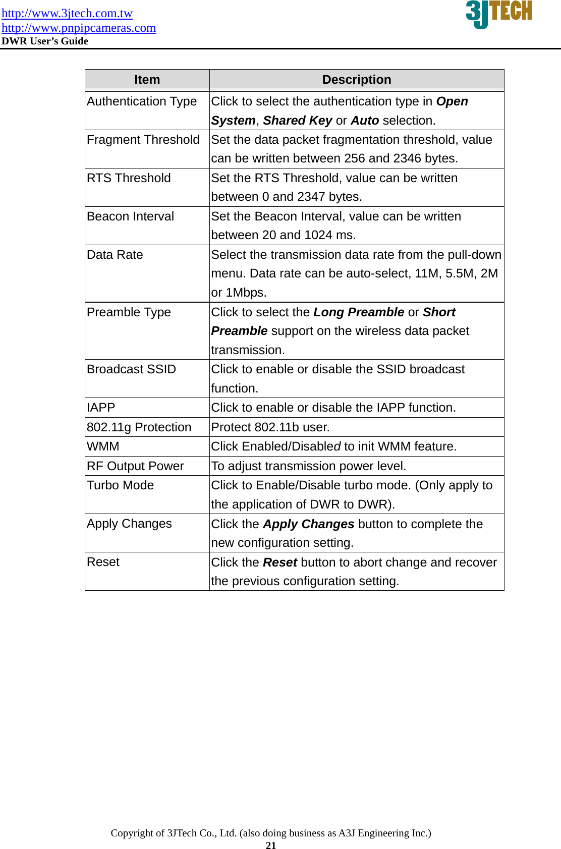
![http://www.3jtech.com.tw http://www.pnpipcameras.com DWR User’s Guide Copyright of 3JTech Co., Ltd. (also doing business as A3J Engineering Inc.) 20 Associated Clients Click the Show Active Clients button to open Active Wireless Client Table that shows the MAC address, transmit-packet, receive-packet and transmission-rate for each associated wireless client. Enable Mac Clone (Single Ethernet Client) Take Laptop NIC MAC address as wireless client MAC address. [Client Mode only] Apply Changes Click the Apply Changes button to complete the new configuration setting. Reset Click the Reset button to abort change and recover the previous configuration setting. 3.2.4.5 Wireless - Advanced Settings These settings are only for more technically advanced users who have a sufficient knowledge about wireless LAN. These settings should not be changed unless you know what effect the changes will have on your DWR. Fig. 3-10](https://usermanual.wiki/3J-Tech/DWRWIFIROUTER/User-Guide-1030966-Page-20.png)
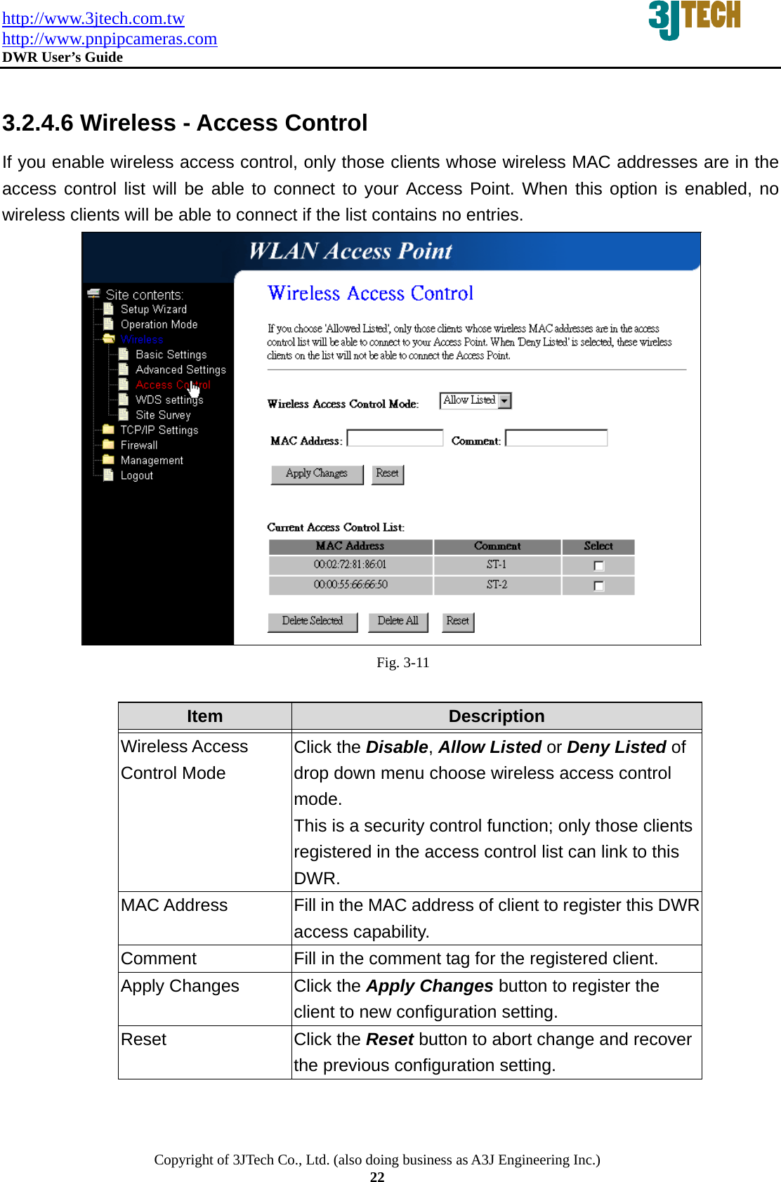
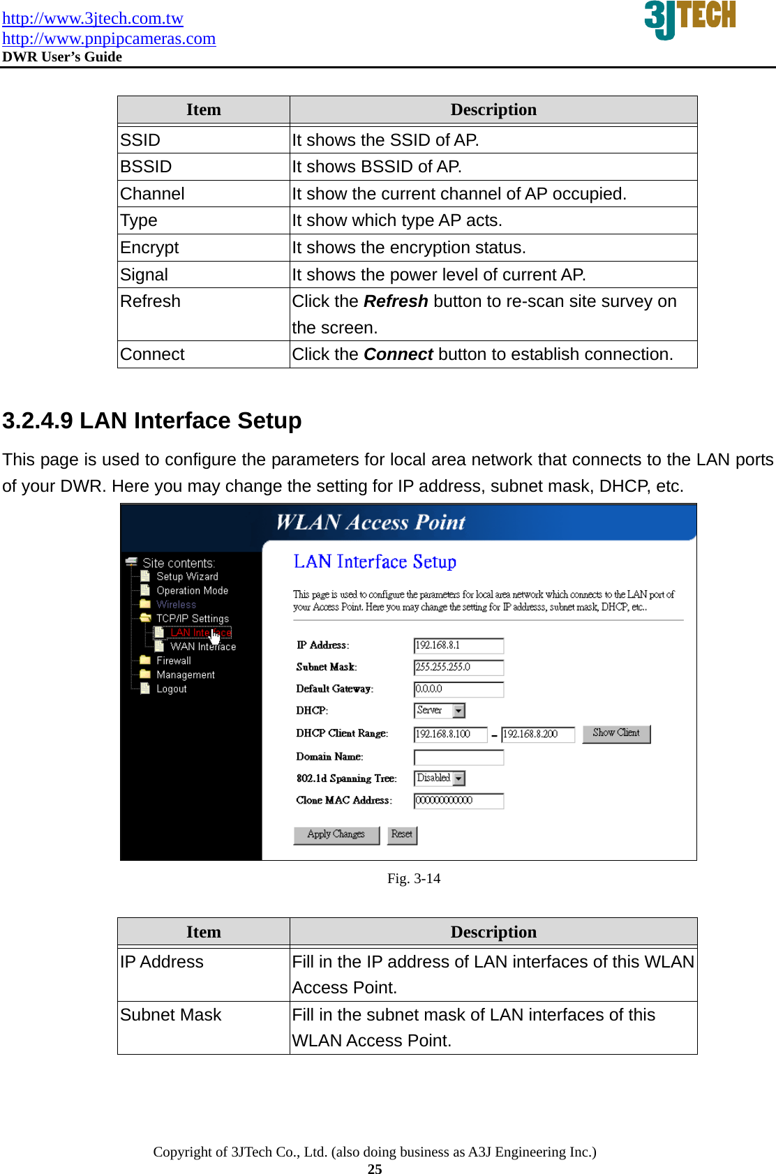
![http://www.3jtech.com.tw http://www.pnpipcameras.com DWR User’s Guide Copyright of 3JTech Co., Ltd. (also doing business as A3J Engineering Inc.) 26 Default Gateway Fill in the default gateway for LAN interfaces out going data packets. DHCP Click to select Disabled, Client or Server in different operation mode of wireless Access Point. DHCP Client Range Fill in the start IP address and end IP address to allocate a range of IP addresses; client with DHCP function set will be assigned an IP address from the range. Show Client Click to open the Active DHCP Client Table window that shows the active clients with their assigned IP address, MAC address and time expired information. [Server mode only] Domain Name Assign Domain Name and dispatch to DHCP clients. It is optional field. 802.1d Spanning Tree Select to enable or disable the IEEE 802.1d Spanning Tree function from the pull-down menu. Clone MAC Address Fill in the MAC address that is the MAC address to be cloned. Apply Changes Click the Apply Changes button to complete the new configuration setting. Reset Click the Reset button to abort change and recover the previous configuration setting.](https://usermanual.wiki/3J-Tech/DWRWIFIROUTER/User-Guide-1030966-Page-26.png)