3J Tech DWRWIFIROUTER Dedicated WiFi Router User Manual
3J Tech. Co., Ltd. Dedicated WiFi Router Users Manual
3J Tech >
Users Manual

Dedicated Wifi Router (DWR)
User’s Guide
Version: 1.1
Date: October 17, 2008
3JTech Co., Ltd.
2F, No. 342, Fu-Shing N. Rd.
Taipei, Taiwan
Tel: +886-2-2500 6916
e-mail: info@3jtech.com.tw

http://www.3jtech.com.tw
http://www.pnpipcameras.com
DWR User’s Guide
Copyright of 3JTech Co., Ltd. (also doing business as A3J Engineering Inc.)
2
Revision History
Version Date Changes
1.0 09/18/2008 First Release of DWR User’s Guide
1.1 10/17/2008 Add the FCC Caution
Table of Contents
Revision History-------------------------------------------------------- 2
TABLE OF CONTENTS -------------------------------------------------- 2
CHAPTER 1. PRODUCT OVERVIEW ----------------------------------------- 4
1.1 INTRODUCTION------------------------------------------------------ 4
1.2 FEATURES --------------------------------------------------------- 5
1.3 PACKAGE CONTENTS ------------------------------------------------- 5
CHAPTER 2. PHYSICAL DESCRIPTION -------------------------------------- 6
2.1 PANELS ---------------------------------------------------------- 6
2.1.1 Front and Rear Panels --------------------------------------------6
2.1.2 Bottom Panel---------------------------------------------------7
2.2 ILLUSTRATION ------------------------------------------------------7
2.2.1 Front and Rear Panel Information ----------------------------------- 8
WAN Port --------------------------------------------------------8
LAN1~LAN 4 Port Network Connectors --------------------------------- 8
wifi ANT SMA Connector -------------------------------------------- 8
Power Supply Connector -------------------------------------------- 8
LEDs ----------------------------------------------------------- 8
2.2.2 Bottom Panel Information -----------------------------------------8
Reset Button------------------------------------------------------ 8
2.2.3 LED Description on the Front Panel --------------------------------- 8
CHAPTER 3. INSTALLATION--------------------------------------------- 10
3.1 HARDWARE INSTALLATION --------------------------------------------- 10
3.2 SOFTWARE INSTALLATION --------------------------------------------- 10
3.2.1 Software Configuration ------------------------------------------ 10
3.2.2 Prepare your PC for DWR Configuration ----------------------------- 11
3.2.3 Connect to DWR ----------------------------------------------- 13
3.2.4 Management and Configuration on DWR ----------------------------- 13
3.2.4.1 Status ---------------------------------------------------- 13
3.2.4.2 Setup Wizard----------------------------------------------- 16
Operation Mode------------------------------------------------- 16
Time Zone Setting ----------------------------------------------- 17
LAN Interface Setup --------------------------------------------- 17
WAN Interface Setup --------------------------------------------- 17
3.2.4.3 Operation Mode--------------------------------------------- 18
3.2.4.4 Wireless - Basic Settings ------------------------------------- 19
3.2.4.5 Wireless - Advanced Settings ---------------------------------- 20
3.2.4.6 Wireless - Access Control ------------------------------------ 22

http://www.3jtech.com.tw
http://www.pnpipcameras.com
DWR User’s Guide
Copyright of 3JTech Co., Ltd. (also doing business as A3J Engineering Inc.)
3
3.2.4.7 WDS Settings ---------------------------------------------- 23
3.2.4.8 Site Survey ------------------------------------------------ 24
3.2.4.9 LAN Interface Setup ----------------------------------------- 25
3.2.4.10 WAN Interface Setup---------------------------------------- 27
Static IP ------------------------------------------------------ 27
DHCP Client --------------------------------------------------- 29
PPPoE -------------------------------------------------------- 30
PPTP--------------------------------------------------------- 33
3.2.4.11 Firewall - Port Filtering ------------------------------------- 35
3.2.4.12 Firewall - IP Filtering --------------------------------------- 36
3.2.4.13 Firewall - MAC Filtering ------------------------------------- 37
3.2.4.14 Firewall - Port Forwarding ----------------------------------- 38
3.2.4.15 Firewall – URL Filtering ------------------------------------- 39
3.2.4.16 Firewall - DMZ -------------------------------------------- 40
3.2.4.17 Management - Statistics ------------------------------------- 41
3.2.4.18 Management - DDNS --------------------------------------- 42
3.2.4.19 Management - Time Zone Setting ------------------------------ 43
3.2.4.20 Management – Denial-of-Service ------------------------------ 44
3.2.4.21 Management - Log ----------------------------------------- 45
3.2.4.22 Management - Upgrade Firmware------------------------------ 46
3.2.4.23 Management - Save/ Reload Settings --------------------------- 46
3.2.4.24 Management - Password Setup -------------------------------- 47
3.2.4.25 Logout--------------------------------------------------- 48
APPENDIX A – FCC CAUTION -------------------------------------------- 49
http://www.3jtech.com.tw
http://www.pnpipcameras.com
DWR User’s Guide
Copyright of 3JTech Co., Ltd. (also doing business as A3J Engineering Inc.)
4
1. Product Overview
1.1 Introduction
DWR (Dedicated WIFI Router), a special WiFi broadband router, not only it can be used as a
regular router but also make 3JTech WIFI cameras Plug-and-Play. With our proprietary wifiDHCP
technology, the WIFI cameras will get the SSID and WEP key automatically from the DWR via
Ethernet connection. The SSID and WEP key are randomly assigned upon the hardware reset of
DWR.

http://www.3jtech.com.tw
http://www.pnpipcameras.com
DWR User’s Guide
Copyright of 3JTech Co., Ltd. (also doing business as A3J Engineering Inc.)
5
1.2 Features
y As VPN client or pass-through.
y Offer 3JTech’s Wifi camera to be Plug-and-Play wifi cameras.
1.3 Package Contents
─ 1 x DWR Router
─ 1 x CD with Quick Installation Guide and User’s Manual
─ 1 x RJ45 Ethernet Cable
─ 1 x Power Adapter
http://www.3jtech.com.tw
http://www.pnpipcameras.com
DWR User’s Guide
Copyright of 3JTech Co., Ltd. (also doing business as A3J Engineering Inc.)
6
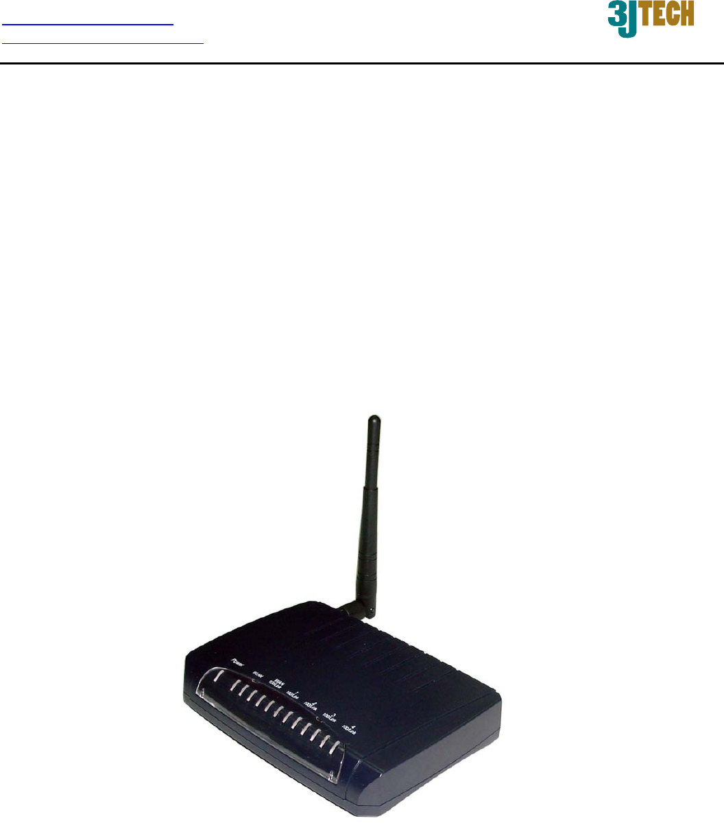
2. Physical Description
The following information contains the physical description of DWR. This includes the functions and
the locations of each connector and indicator. This information provides useful reference when
installing the product. Please familiarize yourself with DWR.
2.1 Panels
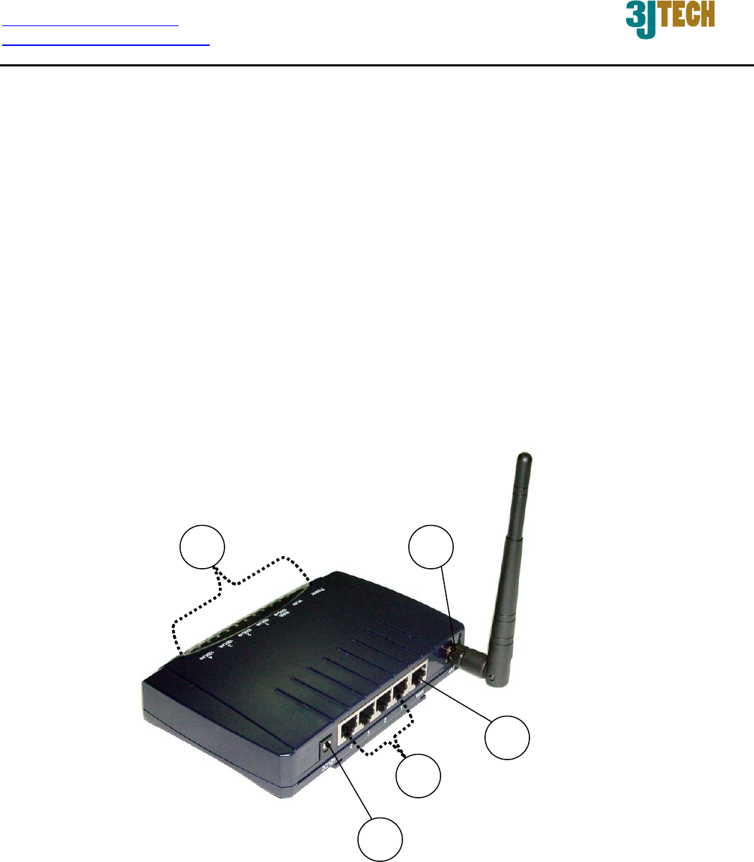
2.1.1 Front and Rear Panels
For more related description, please refer to the Section 2.2 and Section 2.2.1.
2
35
1
4
http://www.3jtech.com.tw
http://www.pnpipcameras.com
DWR User’s Guide
Copyright of 3JTech Co., Ltd. (also doing business as A3J Engineering Inc.)
7
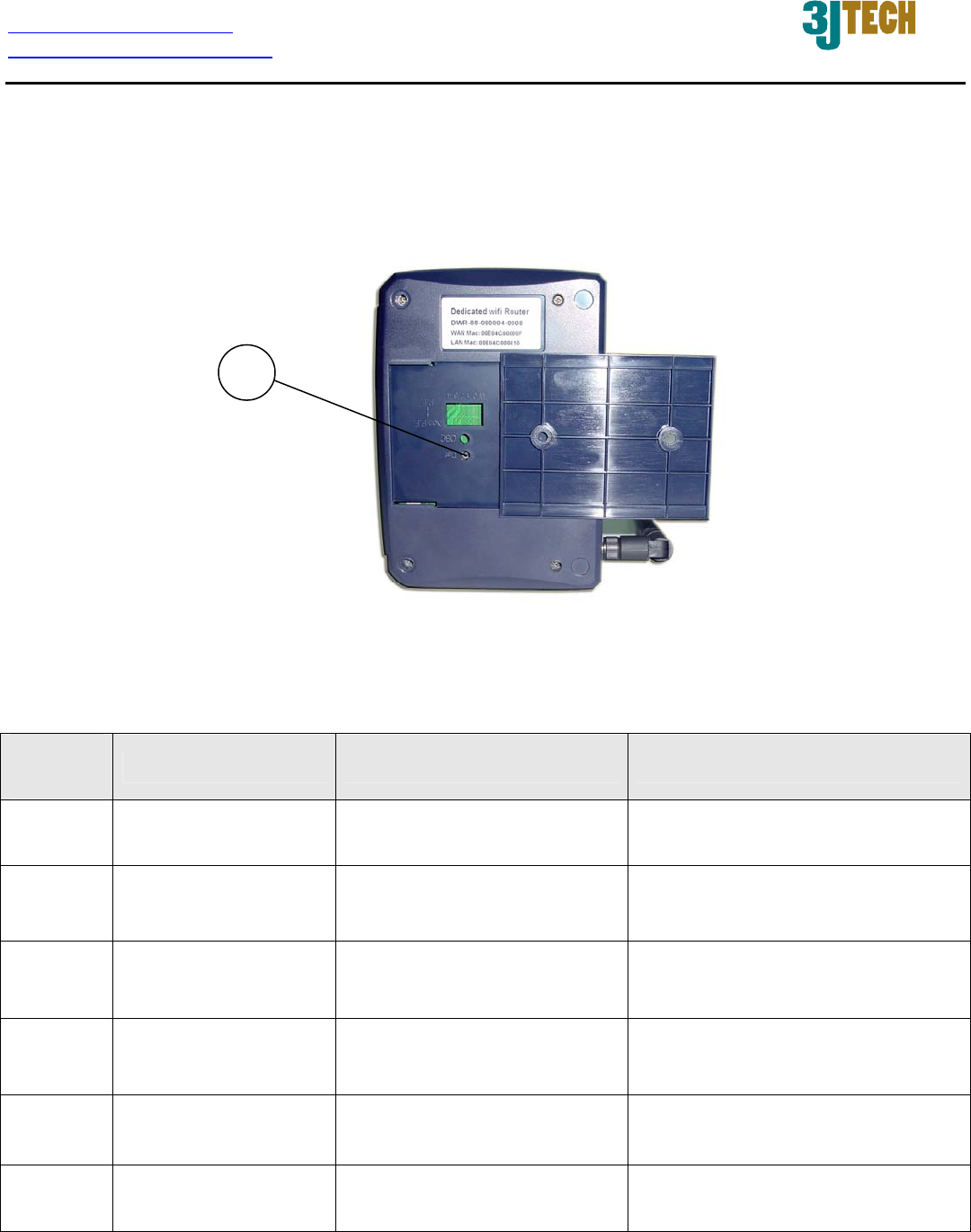
2.1.2 Bottom Panel
For more detailed description, please refer to the Section 2.2 and Section 2.2.2.
2.2 Illustration
No. in
Figures Name on DWR Description Remark
1 WAN Port For the access of Internet Refer to section 2.2.1 for front
and real panels information.
2 LAN1~LAN 4 Port
Network Connectors
To connect to the device and
Ethernet port via RJ45 cable
Refer to section 2.2.1 for front
and real panels information.
3 wifi ANT SMA
Connector
To connect with the wifi
antenna
Refer to section 2.2.1 for front
and real panels information.
4 Power Supply
Connector
To connect with DWR and
the power adapter
Refer to section 2.2.1 for front
and real panels information.
5 LEDs To display the status of
DWR
Refer to section 2.2.3 for LED
description on the front panel.
6 Reset Button To reset DWR to its factory
defaults
Refer to section 2.2.2 for bottom
panel information.
6
http://www.3jtech.com.tw
http://www.pnpipcameras.com
DWR User’s Guide
Copyright of 3JTech Co., Ltd. (also doing business as A3J Engineering Inc.)
8
2.2.1 Front and Rear Panel Information
WAN Port
Offer the access of Internet.
LAN1~LAN 4 Port Network Connectors
DWR is designed for 10/100Mbps Ethernet networks. DWR connects to the network via category 5
cable.
wifi ANT SMA Connector
Support WEP and WPA modes for wireless access.
Power Supply Connector
Plug the power adapter. The specifications of DWR’s power adapter are as follows:
Input: 100 ~ 240V AC, 50/60Hz
Output: 12V DC / 1.5A
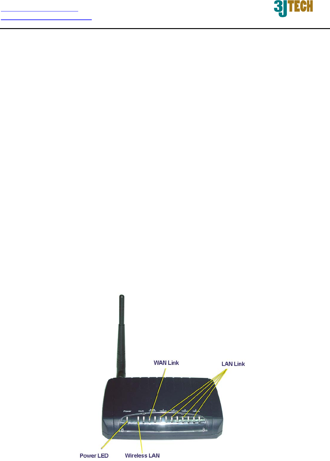
LEDs
Include the LEDs of POWER, WLAN (Wireless LAN), WAN Link and LAN Link.
2.2.2 Bottom Panel Information
Reset Button
Support the hardware reset function.
2.2.3 LED Description on the Front Panel

http://www.3jtech.com.tw
http://www.pnpipcameras.com
DWR User’s Guide
Copyright of 3JTech Co., Ltd. (also doing business as A3J Engineering Inc.)
9
LED Color Status
POWER Green Lit when +12V DC power is on and working.
WLAN(Wireless LAN) Green Lit when device is normal.
Flash when any traffic is present.
WAN Link Green
Lit when connection with remote device is good.
Flash when any traffic is present.
Off when cable connection is not good.
LAN Link Green
Lit when connection with remote device is good.
Flash when any traffic is present.
Off when cable connection is not good.

http://www.3jtech.com.tw
http://www.pnpipcameras.com
DWR User’s Guide
Copyright of 3JTech Co., Ltd. (also doing business as A3J Engineering Inc.)
10
3. Installation
3.1 Hardware Installation
Step 1: Place DWR to the best optimum transmission location. The best transmission location for
your DWR is usually at the geographic center of your wireless network, with line of sign
to all of your mobile stations.
Step 2: Connect DWR to your wired network. Connect the Ethernet WAN interface of DWR by
category 5 Ethernet cable to your switch/ hub/ xDSL modem or cable modem. A
straight-through Ethernet cable with appropriate cable length is needed.
Step 3: Supply DC power to DWR. Use only the AC/DC power adapter supplied with DWR; it
may occur damage by using a different type of power adapter.
3.2 Software Installation
There is no software drivers, patches or utilities installation needed, but only the configuration
settings. Please refer to this chapter which will instruct you how to configure and manage DWR
through the web user interface it supports. With this facility, you can easily access and monitor
through any one LAN port of DWR.
NOTE:
It will take about 55 seconds to complete the boot up sequence after powering on DWR.
3.2.1 Software Configuration
In DWR, it supports a simple user management function to configure the system. The DWR is
delivered with the following factory default parameters on the Ethernet LAN interfaces.
Default IP Address: 192.168.8.1
Default IP subnet mask: 255.255.255.0
WEB login User Name: cameras
WEB login Password: cameras

http://www.3jtech.com.tw
http://www.pnpipcameras.com
DWR User’s Guide
Copyright of 3JTech Co., Ltd. (also doing business as A3J Engineering Inc.)
11
3.2.2 Prepare your PC for DWR Configuration
For OS of Microsoft Windows 95/ 98/ Me:
1. Click the Start button and select Settings, then click Control Panel. The Control Panel
window will appear.
NOTE:
Windows Me users may not see the Network control panel. If so, select View all Control
Panel options on the left side of the window.
2. Move mouse and double-click the right button on Network icon. The Network window will
appear.
3. Check the installed list of Network Components. If TCP/IP is not installed, click the Add
button to install it; otherwise go to step 6.
4. Select Protocol in the Network Component Type dialog box and click Add button.
5. Select TCP/IP in Microsoft of Select Network Protocol dialog box then click OK button to
install the TCP/IP protocol, it may need the Microsoft Windows CD to complete the
installation. Close and go back to Network dialog box after the TCP/IP installation.
6. Select TCP/IP and click the Properties button on the Network dialog box.
7. Select Specify an IP address and type in values as following example.
9 IP Address: 192.168.8.1, any IP address within 192.168.8.1 to 192.168.8.253 is
good to connect the Wireless LAN Access Point.
9 IP Subnet Mask: 255.255.255.0
8. Click OK and reboot your PC after completing the IP parameter settings.

http://www.3jtech.com.tw
http://www.pnpipcameras.com
DWR User’s Guide
Copyright of 3JTech Co., Ltd. (also doing business as A3J Engineering Inc.)
12
For OS of Microsoft Windows 2000, XP:
1. Click the Start button and select Settings, then click Control Panel. The Control Panel
window will appear.
2. Move mouse and double-click the right button on Network and Dial-up Connections icon.
Move mouse and double-click the Local Area Connection icon. The Local Area Connection
window will appear. Click Properties button in the Local Area Connection window.
3. Check the installed list of Network Components. If TCP/IP is not installed, click the Add
button to install it; otherwise go to step 6.
4. Select Protocol in the Network Component Type dialog box and click Add button.
5. Select TCP/IP in Microsoft of Select Network Protocol dialog box then click OK button to
install the TCP/IP protocol, it may need the Microsoft Windows CD to complete the
installation. Close and go back to Network dialog box after the TCP/IP installation.
6. Select TCP/IP and click the Properties button on the Network dialog box.
7. Select Specify an IP address and type in values as following example.
9 IP Address: 192.168.8.1, any IP address within 192.168.8.1 to 192.168.8.253 is
good to connect the Wireless LAN Access Point.
9 IP Subnet Mask: 255.255.255.0
8. Click OK to complete the IP parameter settings.
For OS of Microsoft Windows NT:
1. Click the Start button and select Settings, then click Control Panel. The Control Panel
window will appear.
2. Move mouse and double-click the right button on Network icon. The Network window will
appear. Click Protocol tab from the Network window.
3. Check the installed list of Network Protocol window. If TCP/IP is not installed, click the Add
button to install it; otherwise go to step 6.
4. Select Protocol in the Network Component Type dialog box and click Add button.
5. Select TCP/IP in Microsoft of Select Network Protocol dialog box then click OK button to
install the TCP/IP protocol, it may need the Microsoft Windows CD to complete the
installation. Close and go back to Network dialog box after the TCP/IP installation.
6. Select TCP/IP and click the Properties button on the Network dialog box.
7. Select Specify an IP address and type in values as following example.
9 IP Address: 192.168.8.1, any IP address within 192.168.8.1 to 192.168.8.253 is
good to connect the Wireless LAN Access Point.
9 IP Subnet Mask: 255.255.255.0
8. Click OK to complete the IP parameter settings.
http://www.3jtech.com.tw
http://www.pnpipcameras.com
DWR User’s Guide
Copyright of 3JTech Co., Ltd. (also doing business as A3J Engineering Inc.)
13
3.2.3 Connect to DWR
After DWR has been connected to your PC via the network cable, please initiate a web browser, i.e.
Microsoft Internet Explore and enter http://192.168.8.1 on the URL to login DWR. Then, input the
default user name as well as the password, and click the OK button. The setup page for DWR will be
displayed once the login process is successful.
As the figure below shows, for example, left section is the whole list of sub functions while each of
main functions, including Setup Wizard, Operation Mode, Wireless, TCP/IP Settings, Firewall,
Management and Logout is selected.
Fig. 3-1
3.2.4 Management and Configuration on DWR
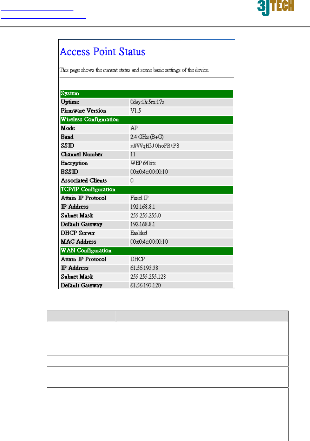
3.2.4.1 Status
This page shows the current status and some basic settings of the device, includes system, wireless,
Ethernet LAN and WAN configuration information.
http://www.3jtech.com.tw
http://www.pnpipcameras.com
DWR User’s Guide
Copyright of 3JTech Co., Ltd. (also doing business as A3J Engineering Inc.)
14
Fig. 3-2
Item Description
System
Uptime It shows the duration since DWR is powered on.
Firmware version It shows the firmware version of DWR.
Wireless Configuration
Mode It shows wireless operation mode.
Band It shows the current wireless operating frequency.
SSID It shows the SSID of this DWR.
The SSID is the unique name of DWR and shared
among its service area, so all devices attempts to join
the same wireless network can identify it.
Channel Number It shows the wireless channel connected currently.

http://www.3jtech.com.tw
http://www.pnpipcameras.com
DWR User’s Guide
Copyright of 3JTech Co., Ltd. (also doing business as A3J Engineering Inc.)
15
Encryption It shows the status of encryption function.
BSSID It shows the BSSID address of DWR. BSSID is a
six-byte address.
Associated Clients It shows the number of connected clients (or stations,
PCs).
TCP/IP Configuration
Attain IP Protocol It shows type of connection.
IP Address It shows the IP address of LAN interfaces of DWR.
Subnet Mask It shows the IP subnet mask of LAN interfaces of DWR.
Default Gateway It shows the default gateway setting for LAN interfaces
outgoing data packets.
DHCP Server It shows the DHCP server is enabled or not.
MAC Address It shows the MAC address of LAN interfaces of DWR.
WAN Configuration
Attain IP Protocol It shows how DWR gets the IP address. The IP address
can be set manually to a fixed one or set dynamically by
DHCP server or attain IP by PPPoE / PPTP connection.
IP Address It shows the IP address of WAN interface of DWR.
Subnet Mask It shows the IP subnet mask of WAN interface of DWR.
Default Gateway It shows the default gateway setting for WAN interface
outgoing data packets.
MAC Address It shows the MAC address of WAN interface of DWR.
http://www.3jtech.com.tw
http://www.pnpipcameras.com
DWR User’s Guide
Copyright of 3JTech Co., Ltd. (also doing business as A3J Engineering Inc.)
16
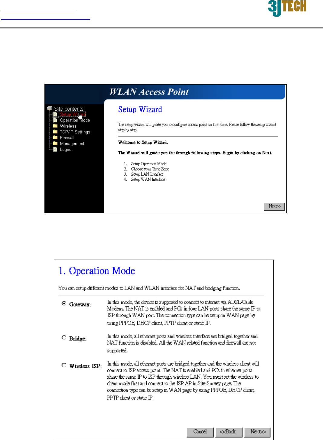
3.2.4.2 Setup Wizard
This page guides you to configure DWR for the first time. Please press Next to continue.
Fig. 3-3
Operation Mode
This page followed by Setup Wizard page to define the operation mode.
Fig. 3-4
http://www.3jtech.com.tw
http://www.pnpipcameras.com
DWR User’s Guide
Copyright of 3JTech Co., Ltd. (also doing business as A3J Engineering Inc.)
17
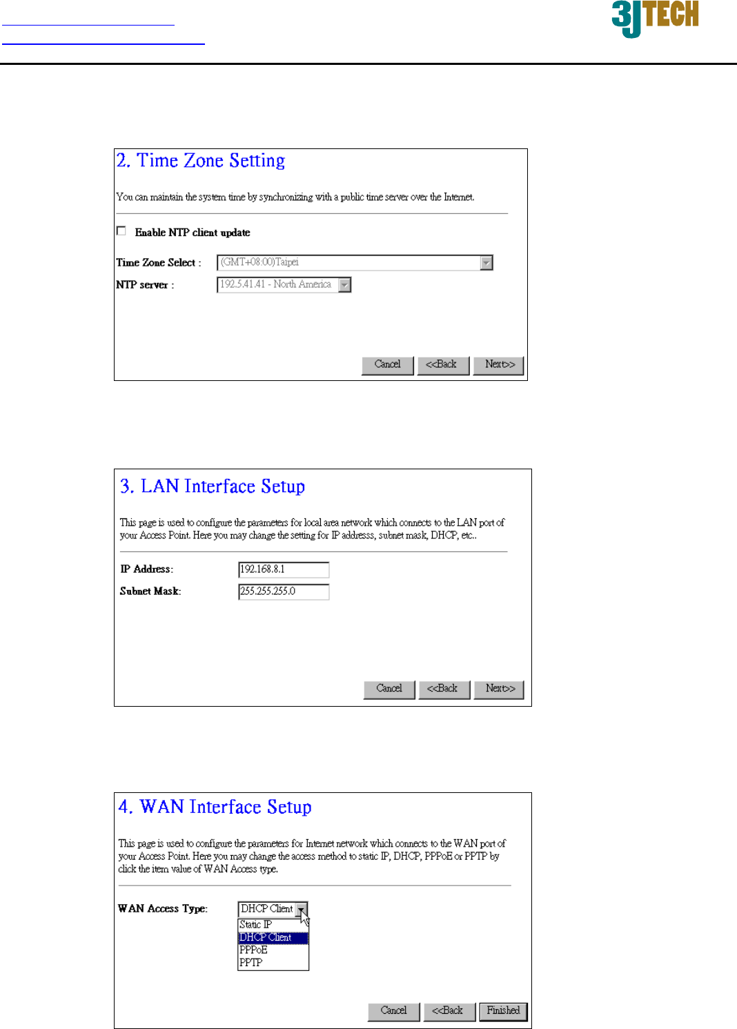
Time Zone Setting
This page is used to enable and configure NTP client.
Fig. 3-5
LAN Interface Setup
This page is used to configure local area network IP address and subnet mask.
Fig. 3-6
WAN Interface Setup
This page is used to configure WAN access type.
Fig. 3-7
http://www.3jtech.com.tw
http://www.pnpipcameras.com
DWR User’s Guide
Copyright of 3JTech Co., Ltd. (also doing business as A3J Engineering Inc.)
18
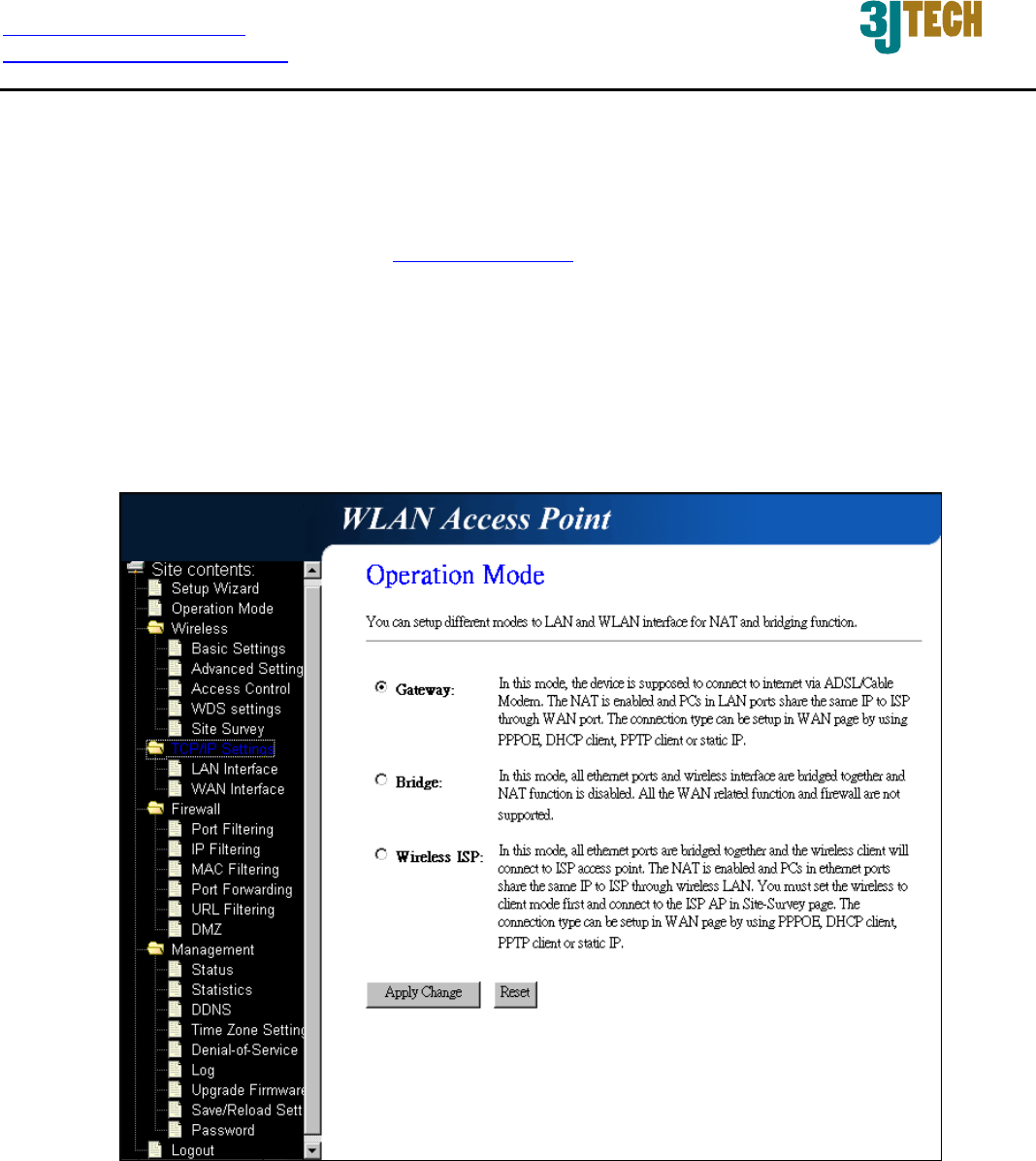
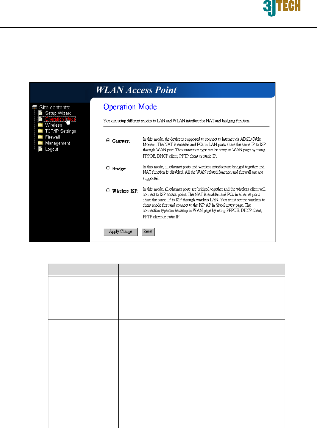
3.2.4.3 Operation Mode
This page is used to configure which mode that DWR will act.
Fig. 3-8
Item Description
Gateway Traditional gateway configuration. It always
connects Internet via ADSL/Cable Modem. LAN
interface, WAN interface, Wireless interface, NAT
and Firewall modules are applied to this mode.
Bridge Each interface (LAN, WAN and Wireless) regards as
bridge. NAT, Firewall and all router’s functions are
not supported.
Wireless ISP Switch Wireless interface to WAN port and all
Ethernet ports in bridge mode. Wireless interface
can do all router’s functions.
Apply Changes Click the Apply Changes button to complete the
new configuration setting.
Reset Click the Reset button to abort change and recover
the previous configuration setting.
http://www.3jtech.com.tw
http://www.pnpipcameras.com
DWR User’s Guide
Copyright of 3JTech Co., Ltd. (also doing business as A3J Engineering Inc.)
19
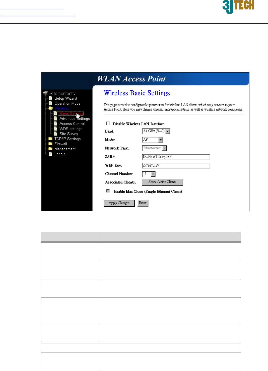
3.2.4.4 Wireless - Basic Settings
This page is used to configure the parameters for wireless LAN clients that may connect to your
DWR. Here you may change wireless encryption settings as well as wireless network parameters.
Fig. 3-9
Item Description
Disable Wireless LAN
Interface
Click on to disable the wireless LAN data
transmission.
Band Click to select 2.4GHz(B) / 2.4GHz(G) /
2.4GHz(B+G).
Mode Click to select the WLAN AP / Client / WDS /
AP+WDS wireless mode.
Network Type Support Inferstructure mode in wireless network
connection. In this mode, the device can connect to
DWR.
SSID It is the wireless network name. The SSID can be 32
bytes long.
WEP Key 64Bit encryption algorithm.
Channel Number Select the wireless communication channel from the
pull-down menu.
http://www.3jtech.com.tw
http://www.pnpipcameras.com
DWR User’s Guide
Copyright of 3JTech Co., Ltd. (also doing business as A3J Engineering Inc.)
20
Associated Clients Click the Show Active Clients button to open Active
Wireless Client Table that shows the MAC address,
transmit-packet, receive-packet and
transmission-rate for each associated wireless
client.
Enable Mac Clone
(Single Ethernet
Client)
Take Laptop NIC MAC address as wireless client
MAC address. [Client Mode only]
Apply Changes Click the Apply Changes button to complete the
new configuration setting.
Reset Click the Reset button to abort change and recover
the previous configuration setting.
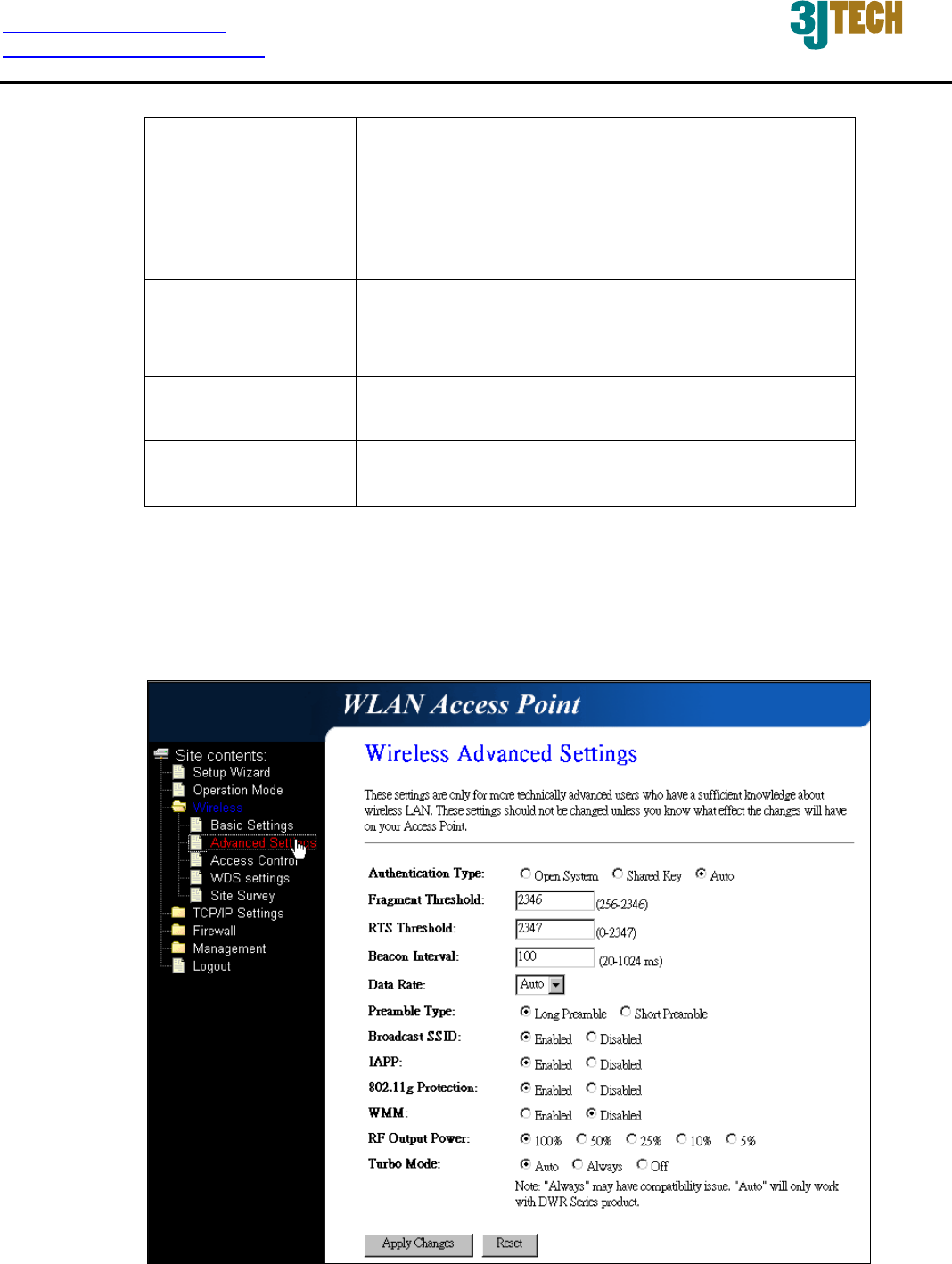
3.2.4.5 Wireless - Advanced Settings
These settings are only for more technically advanced users who have a sufficient knowledge about
wireless LAN. These settings should not be changed unless you know what effect the changes will
have on your DWR.
Fig. 3-10

http://www.3jtech.com.tw
http://www.pnpipcameras.com
DWR User’s Guide
Copyright of 3JTech Co., Ltd. (also doing business as A3J Engineering Inc.)
21
Item Description
Authentication Type Click to select the authentication type in Open
System, Shared Key or Auto selection.
Fragment Threshold Set the data packet fragmentation threshold, value
can be written between 256 and 2346 bytes.
RTS Threshold Set the RTS Threshold, value can be written
between 0 and 2347 bytes.
Beacon Interval Set the Beacon Interval, value can be written
between 20 and 1024 ms.
Data Rate Select the transmission data rate from the pull-down
menu. Data rate can be auto-select, 11M, 5.5M, 2M
or 1Mbps.
Preamble Type Click to select the Long Preamble or Short
Preamble support on the wireless data packet
transmission.
Broadcast SSID Click to enable or disable the SSID broadcast
function.
IAPP Click to enable or disable the IAPP function.
802.11g Protection Protect 802.11b user.
WMM Click Enabled/Disabled to init WMM feature.
RF Output Power To adjust transmission power level.
Turbo Mode Click to Enable/Disable turbo mode. (Only apply to
the application of DWR to DWR).
Apply Changes Click the Apply Changes button to complete the
new configuration setting.
Reset Click the Reset button to abort change and recover
the previous configuration setting.
http://www.3jtech.com.tw
http://www.pnpipcameras.com
DWR User’s Guide
Copyright of 3JTech Co., Ltd. (also doing business as A3J Engineering Inc.)
22
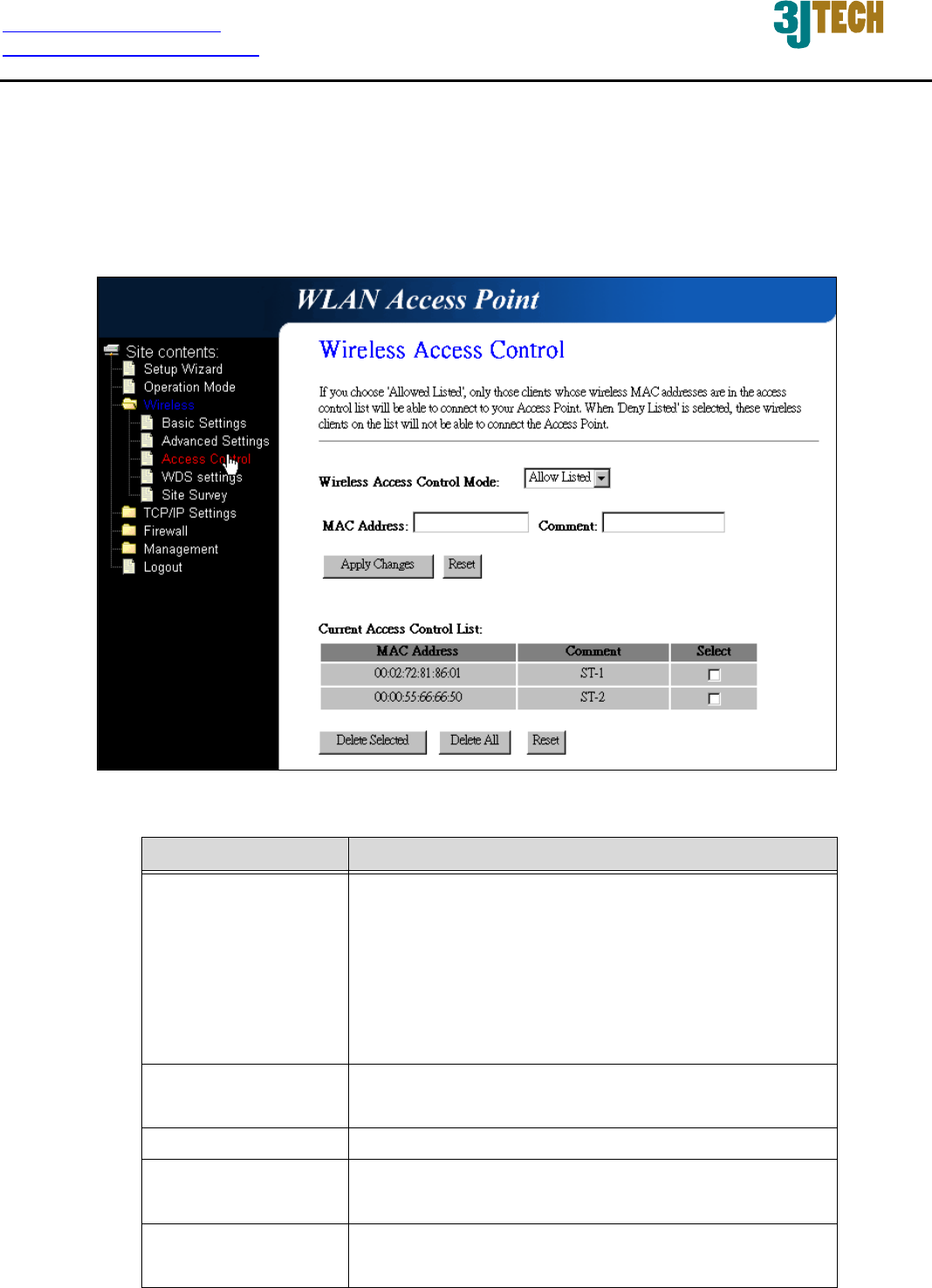
3.2.4.6 Wireless - Access Control
If you enable wireless access control, only those clients whose wireless MAC addresses are in the
access control list will be able to connect to your Access Point. When this option is enabled, no
wireless clients will be able to connect if the list contains no entries.
Fig. 3-11
Item Description
Wireless Access
Control Mode
Click the Disable, Allow Listed or Deny Listed of
drop down menu choose wireless access control
mode.
This is a security control function; only those clients
registered in the access control list can link to this
DWR.
MAC Address Fill in the MAC address of client to register this DWR
access capability.
Comment Fill in the comment tag for the registered client.
Apply Changes Click the Apply Changes button to register the
client to new configuration setting.
Reset Click the Reset button to abort change and recover
the previous configuration setting.
http://www.3jtech.com.tw
http://www.pnpipcameras.com
DWR User’s Guide
Copyright of 3JTech Co., Ltd. (also doing business as A3J Engineering Inc.)
23
Current Access
Control List
It shows the registered clients that are allowed to
link to this DWR.
Delete Selected Click to delete the selected clients that will be
access right removed from this DWR.
Delete All Click to delete all the registered clients from the
access allowed list.
Reset Click the Reset button to abort change and recover
the previous configuration setting.
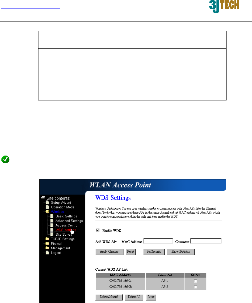
3.2.4.7 WDS Settings
Wireless Distribution System uses wireless media to communicate with other APs, like the Ethernet
does. To do this, you must set these APs in the same channel and set MAC address of other AP that
you want to communicate with in the table and then enable the WDS.
NOTE: WDS / AP + WDS mode must be selected in Wireless Basic Settings if you would like to enable the
function of WDS settings.
Fig. 3-12
http://www.3jtech.com.tw
http://www.pnpipcameras.com
DWR User’s Guide
Copyright of 3JTech Co., Ltd. (also doing business as A3J Engineering Inc.)
24
Item Description
Enable WDS Click the checkbox to enable wireless distribution
system function.
MAC Address Fill in the MAC address of AP to register the wireless
distribution system access capability.
Comment Fill in the comment tag for the registered AP.
Apply Changes Click the Apply Changes button to register the AP
to new configuration setting.
Reset Click the Reset button to abort change and recover
the previous configuration setting.
Set Security Click button to configure wireless security like
WEP(64bits), WEP(128bits), WPA(TKIP),
WPA2(AES) or None
Show Statistics It shows the TX, RX packets, rate statistics
Delete Selected Click to delete the selected clients that will be
removed from the wireless distribution system.
Delete All Click to delete all the registered APs from the
wireless distribution system allowed list.
Reset Click the Reset button to abort change and recover
the previous configuration setting.
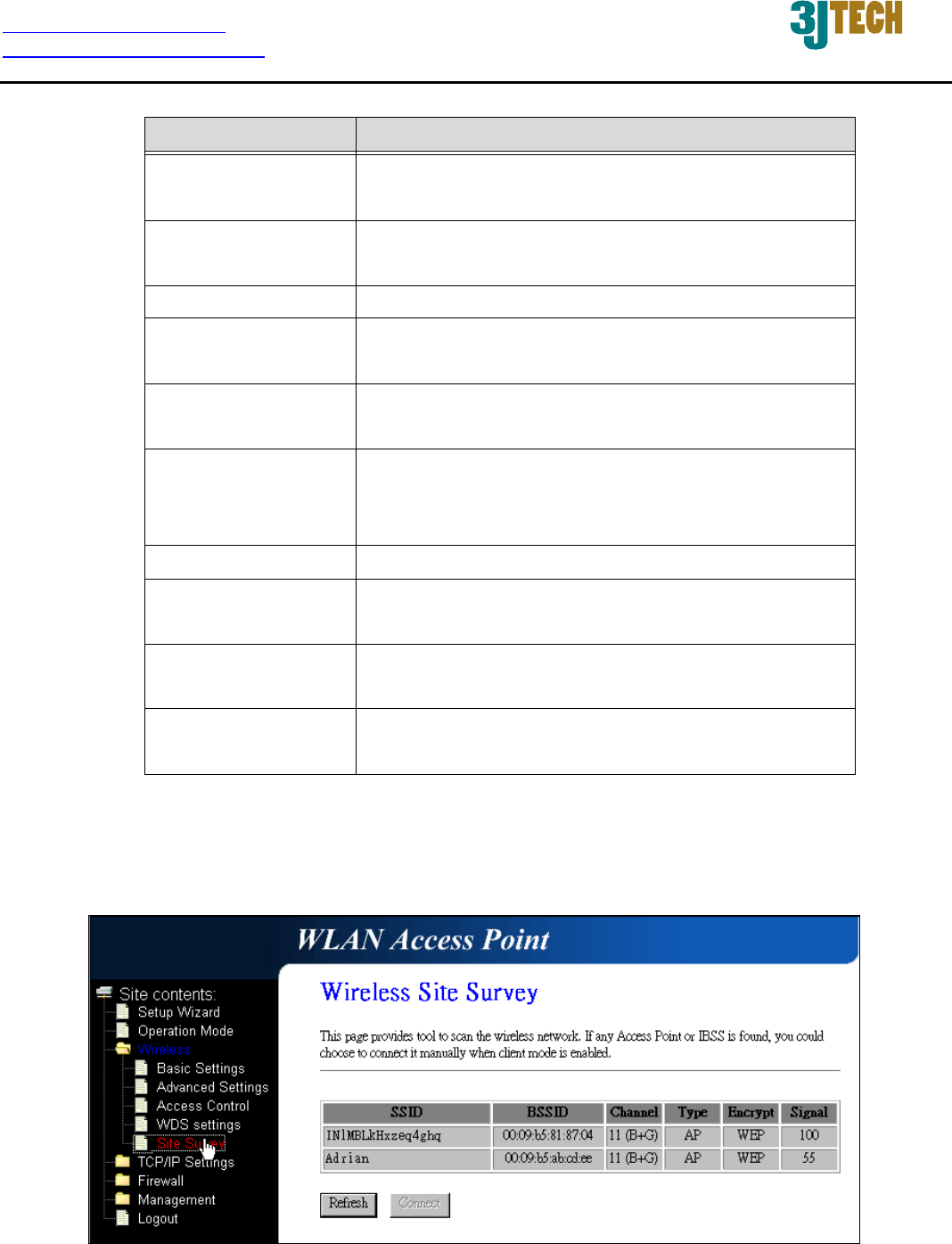
3.2.4.8 Site Survey
This page is used to view or configure other APs near yours.
Fig. 3-13
http://www.3jtech.com.tw
http://www.pnpipcameras.com
DWR User’s Guide
Copyright of 3JTech Co., Ltd. (also doing business as A3J Engineering Inc.)
25
Item Description
SSID It shows the SSID of AP.
BSSID It shows BSSID of AP.
Channel It show the current channel of AP occupied.
Type It show which type AP acts.
Encrypt It shows the encryption status.
Signal It shows the power level of current AP.
Refresh Click the Refresh button to re-scan site survey on
the screen.
Connect Click the Connect button to establish connection.
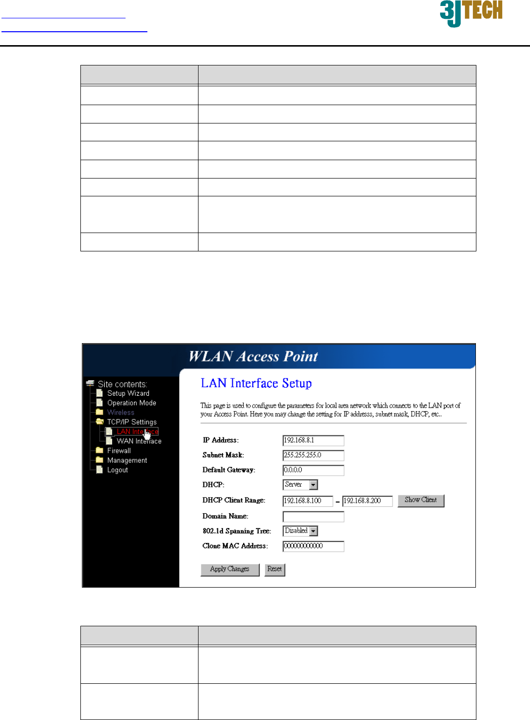
3.2.4.9 LAN Interface Setup
This page is used to configure the parameters for local area network that connects to the LAN ports
of your DWR. Here you may change the setting for IP address, subnet mask, DHCP, etc.
Fig. 3-14
Item Description
IP Address Fill in the IP address of LAN interfaces of this WLAN
Access Point.
Subnet Mask Fill in the subnet mask of LAN interfaces of this
WLAN Access Point.

http://www.3jtech.com.tw
http://www.pnpipcameras.com
DWR User’s Guide
Copyright of 3JTech Co., Ltd. (also doing business as A3J Engineering Inc.)
26
Default Gateway Fill in the default gateway for LAN interfaces out
going data packets.
DHCP Click to select Disabled, Client or Server in
different operation mode of wireless Access Point.
DHCP Client Range Fill in the start IP address and end IP address to
allocate a range of IP addresses; client with DHCP
function set will be assigned an IP address from the
range.
Show Client Click to open the Active DHCP Client Table window
that shows the active clients with their assigned IP
address, MAC address and time expired
information. [Server mode only]
Domain Name
A
ssign Domain Name and dispatch to DHCP clients.
It is optional field.
802.1d Spanning
Tree
Select to enable or disable the IEEE 802.1d
Spanning Tree function from the pull-down menu.
Clone MAC Address Fill in the MAC address that is the MAC address to
be cloned.
Apply Changes Click the Apply Changes button to complete the
new configuration setting.
Reset Click the Reset button to abort change and recover
the previous configuration setting.
http://www.3jtech.com.tw
http://www.pnpipcameras.com
DWR User’s Guide
Copyright of 3JTech Co., Ltd. (also doing business as A3J Engineering Inc.)
27
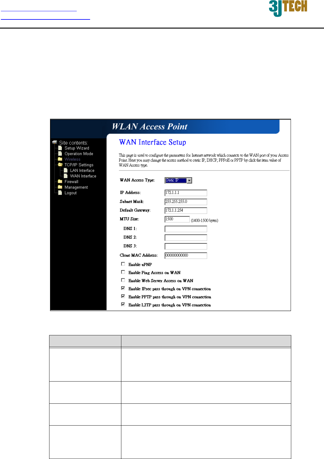
3.2.4.10 WAN Interface Setup
This page is used to configure the parameters for wide area network that connects to the WAN port
of your DWR. Here you may change the access method to Static IP, DHCP, PPPoE or PPTP by
clicking the item value of WAN Access Type.
Static IP
Fig. 3-15
Item Description
Static IP Click to select Static IP support on WAN interface.
There are IP address, subnet mask and default
gateway settings need to be done.
IP Address If you select the Static IP support on WAN interface,
fill in the IP address for it.
Subnet Mask If you select the Static IP support on WAN interface,
fill in the subnet mask for it.
Default Gateway If you select the Static IP support on WAN interface,
fill in the default gateway for WAN interface out
going data packets.

http://www.3jtech.com.tw
http://www.pnpipcameras.com
DWR User’s Guide
Copyright of 3JTech Co., Ltd. (also doing business as A3J Engineering Inc.)
28
MTU Size Fill in the mtu size of MTU Size. The default value is
1400.
DNS 1 Fill in the IP address of Domain Name Server 1.
DNS 2 Fill in the IP address of Domain Name Server 2.
DNS 3 Fill in the IP address of Domain Name Server 3.
Clone MAC Address Fill in the MAC address that is the MAC address to
be cloned.
Enable uPNP Click the checkbox to enable uPNP function.
Enable Ping Access
on WAN
Click the checkbox to enable Ping Access on WAN
function.
Enable Web Server
Access on WAN
Click the checkbox to enable web configuration from
WAN side.
Enable IPsec pass
through on VPN
connection
Click the checkbox to enable IPSec packet pass
through.
Enable PPTP pass
through on VPN
connection
Click the checkbox to enable PPTP packet pass
through.
Enable L2TP pass
through on VPN
connection
Click the checkbox to enable L2TP packet pass
through.
Apply Changes Click the Apply Changes button to complete the
new configuration setting.
Reset Click the Reset button to abort change and recover
the previous configuration setting.
http://www.3jtech.com.tw
http://www.pnpipcameras.com
DWR User’s Guide
Copyright of 3JTech Co., Ltd. (also doing business as A3J Engineering Inc.)
29
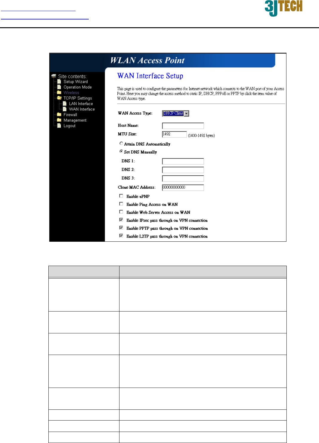
DHCP Client
Fig. 3-16
Item Description
DHCP Client Click to select DHCP support on WAN interface for
IP address assigned automatically from a DHCP
server.
Host Name Fill in the host name of Host Name. The default
value is empty.
MTU Size Fill in the mtu size of MTU Size. The default value is
1400.
Attain DNS
Automatically
Click to select getting DNS address for DHCP
support. Please select Set DNS Manually if the
DHCP support is selected.
Set DNS Manually Click to select getting DNS address for DHCP
support.
DNS 1 Fill in the IP address of Domain Name Server 1.
DNS 2 Fill in the IP address of Domain Name Server 2.
DNS 3 Fill in the IP address of Domain Name Server 3.

http://www.3jtech.com.tw
http://www.pnpipcameras.com
DWR User’s Guide
Copyright of 3JTech Co., Ltd. (also doing business as A3J Engineering Inc.)
30
Clone MAC Address Fill in the MAC address that is the MAC address to
be cloned.
Enable uPNP Click the checkbox to enable uPNP function.
Enable Ping Access
on WAN
Click the checkbox to enable Ping Access on WAN
function.
Enable Web Server
Access on WAN
Click the checkbox to enable web configuration from
WAN side.
Enable IPsec pass
through on VPN
connection
Click the checkbox to enable IPSec packet pass
through.
Enable PPTP pass
through on VPN
connection
Click the checkbox to enable PPTP packet pass
through.
Enable L2TP pass
through on VPN
connection
Click the checkbox to enable L2TP packet pass
through.
Apply Changes Click the Apply Changes button to complete the
new configuration setting.
Reset Click the Reset button to abort change and recover
the previous configuration setting.
PPPoE
Fig. 3-17

http://www.3jtech.com.tw
http://www.pnpipcameras.com
DWR User’s Guide
Copyright of 3JTech Co., Ltd. (also doing business as A3J Engineering Inc.)
31
Item Description
PPPoE Click to select PPPoE support on WAN interface.
There are user name, password, connection type
and idle time settings need to be done.
User Name If you select the PPPoE support on WAN interface,
fill in the user name and password to login the
PPPoE server.
Password If you select the PPPoE support on WAN interface,
fill in the user name and password to login the
PPPoE server.
Service Name Fill in the service name of Service Name. The
default value is empty.
Connection Type Select the connection type from pull-down menu.
There are Continuous, Connect on Demand and
Manual three types to select.
Continuous connection type means to setup the
connection through PPPoE protocol whenever this
DWR is powered on.
Connect on Demand connection type means to
setup the connection through PPPoE protocol
whenever you send the data packets out through the
WAN interface; there are a watchdog implemented
to close the PPPoE connection while there are no
data sent out longer than the idle time set.
Manual connection type means to setup the
connection through the PPPoE protocol by clicking
the Connect button manually, and clicking the
Disconnect button manually.
Idle Time If you select the PPPoE and Connect on Demand
connection type, fill in the idle time for
auto-disconnect function. Value can be between 1
and 1000 minutes.
MTU Size Fill in the mtu size of MTU Size. The default value is
1400.
Attain DNS
Automatically
Click to select getting DNS address for PPPoE
support. Please select Set DNS Manually if the
PPPoE support is selected.

http://www.3jtech.com.tw
http://www.pnpipcameras.com
DWR User’s Guide
Copyright of 3JTech Co., Ltd. (also doing business as A3J Engineering Inc.)
32
Set DNS Manually Click to select getting DNS address for Static IP
support.
DNS 1 Fill in the IP address of Domain Name Server 1.
DNS 2 Fill in the IP address of Domain Name Server 2.
DNS 3 Fill in the IP address of Domain Name Server 3.
Clone MAC Address Fill in the MAC address that is the MAC address to
be cloned.
Enable uPNP Click the checkbox to enable uPNP function.
Enable Ping Access
on WAN
Click the checkbox to enable Ping Access on WAN
function.
Enable Web Server
Access on WAN
Click the checkbox to enable web configuration from
WAN side.
Enable IPsec pass
through on VPN
connection
Click the checkbox to enable IPSec packet pass
through.
Enable PPTP pass
through on VPN
connection
Click the checkbox to enable PPTP packet pass
through.
Enable L2TP pass
through on VPN
connection
Click the checkbox to enable L2TP packet pass
through.
Apply Changes Click the Apply Changes button to complete the
new configuration setting.
Reset Click the Reset button to abort change and recover
the previous configuration setting.
http://www.3jtech.com.tw
http://www.pnpipcameras.com
DWR User’s Guide
Copyright of 3JTech Co., Ltd. (also doing business as A3J Engineering Inc.)
33
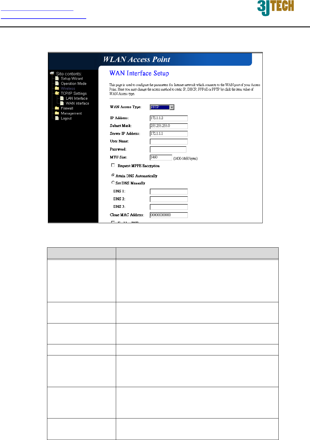
PPTP
Fig. 3-18
Item Description
PPTP
A
llow user to make a tunnel with remote site directly
to secure the data transmission among the
connection. User can use embedded PPTP client
supported by this router to make a VPN connection.
IP Address If you select the PPTP support on WAN interface, fill
in the IP address for it.
Subnet Mask If you select the PPTP support on WAN interface, fill
in the subnet mask for it.
Server IP Address Enter the IP address of the PPTP Server.
User Name If you select the PPTP support on WAN interface, fill
in the user name and password to login the PPTP
server.
Password If you select the PPTP support on WAN interface, fill
in the user name and password to login the PPTP
server.
MTU Size Fill in the mtu size of MTU Size. The default value is
1400.

http://www.3jtech.com.tw
http://www.pnpipcameras.com
DWR User’s Guide
Copyright of 3JTech Co., Ltd. (also doing business as A3J Engineering Inc.)
34
Request MPPE
Encryption
Click the checkbox to enable request MPPE
encryption.
Attain DNS
Automatically
Click to select getting DNS address for PPTP
support. Please select Set DNS Manually if the
PPTP support is selected.
Set DNS Manually Click to select getting DNS address for PPTP
support.
DNS 1 Fill in the IP address of Domain Name Server 1.
DNS 2 Fill in the IP address of Domain Name Server 2.
DNS 3 Fill in the IP address of Domain Name Server 3.
Clone MAC Address Fill in the MAC address that is the MAC address to
be cloned.
Enable uPNP Click the checkbox to enable uPNP function.
Enable Ping Access
on WAN
Click the checkbox to enable Ping Access on WAN
function.
Enable Web Server
Access on WAN
Click the checkbox to enable web configuration from
WAN side.
Enable IPsec pass
through on VPN
connection
Click the checkbox to enable IPSec packet pass
through.
Enable PPTP pass
through on VPN
connection
Click the checkbox to enable PPTP packet pass
through.
Enable L2TP pass
through on VPN
connection
Click the checkbox to enable L2TP packet pass
through.
Apply Changes Click the Apply Changes button to complete the
new configuration setting.
Reset Click the Reset button to abort change and recover
the previous configuration setting.
http://www.3jtech.com.tw
http://www.pnpipcameras.com
DWR User’s Guide
Copyright of 3JTech Co., Ltd. (also doing business as A3J Engineering Inc.)
35
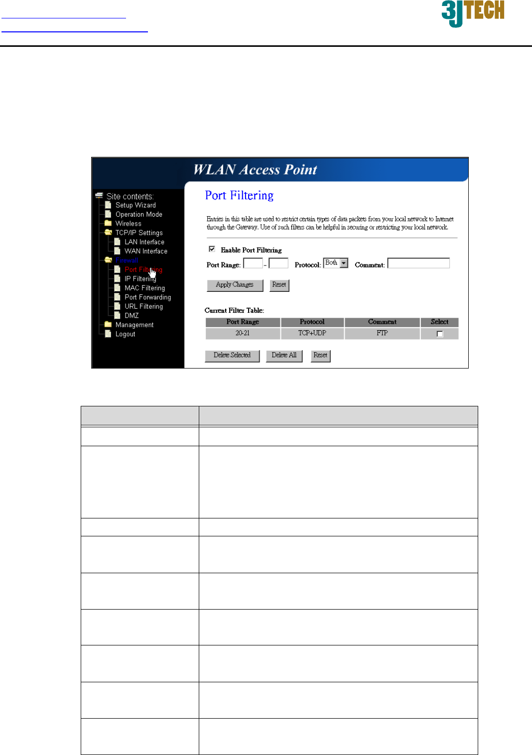
3.2.4.11 Firewall - Port Filtering
Entries in this table are used to restrict certain types of data packets from your local network to
Internet through the Gateway. Use of such filters can be helpful in securing or restricting your local
network.
Fig. 3-19
Item Description
Enable Port Filtering Click to enable the port filtering security function.
Port Range To restrict data transmission from the local network
on certain ports, fill in the range of start-port and
end-port, and the protocol, also put your comments
on it.
Protocol The Protocol can be TCP, UDP or Both.
Comment Comment let you know about the reason to restrict
data from the ports.
Apply Changes Click the Apply Changes button to register the ports
to port filtering list.
Reset Click the Reset button to abort change and recover
the previous configuration setting.
Delete Selected Click to delete the selected port range that will be
removed from the port-filtering list.
Delete All Click to delete all the registered entries from the
port-filtering list.
Reset Click the Reset button to abort change and recover
the previous configuration setting.
http://www.3jtech.com.tw
http://www.pnpipcameras.com
DWR User’s Guide
Copyright of 3JTech Co., Ltd. (also doing business as A3J Engineering Inc.)
36
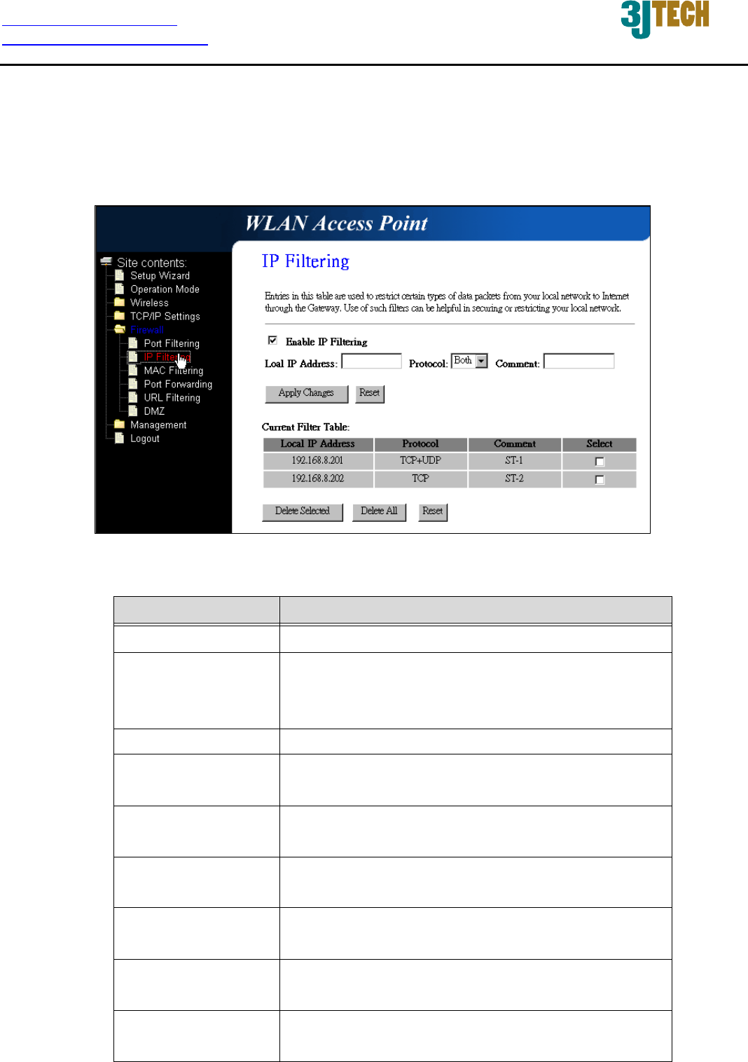
3.2.4.12 Firewall - IP Filtering
Entries in this table are used to restrict certain types of data packets from your local network to
Internet through the Gateway. Use of such filters can be helpful in securing or restricting your local
network.
Fig. 3-20
Item Description
Enable IP Filtering Click to enable the IP filtering security function.
Local IP Address To restrict data transmission from local network on
certain IP addresses, fill in the IP address and the
protocol, also put your comments on it.
Protocol The Protocol can be TCP, UDP or Both.
Comment Comment let you know about the reason to restrict
data from the IP address.
Apply Changes Click the Apply Changes button to register the IP
address to IP filtering list.
Reset Click the Reset button to abort change and recover
the previous configuration setting.
Delete Selected Click to delete the selected IP address that will be
removed from the IP-filtering list.
Delete All Click to delete all the registered entries from the
IP-filtering list.
Reset Click the Reset button to abort change and recover
the previous configuration setting.
http://www.3jtech.com.tw
http://www.pnpipcameras.com
DWR User’s Guide
Copyright of 3JTech Co., Ltd. (also doing business as A3J Engineering Inc.)
37
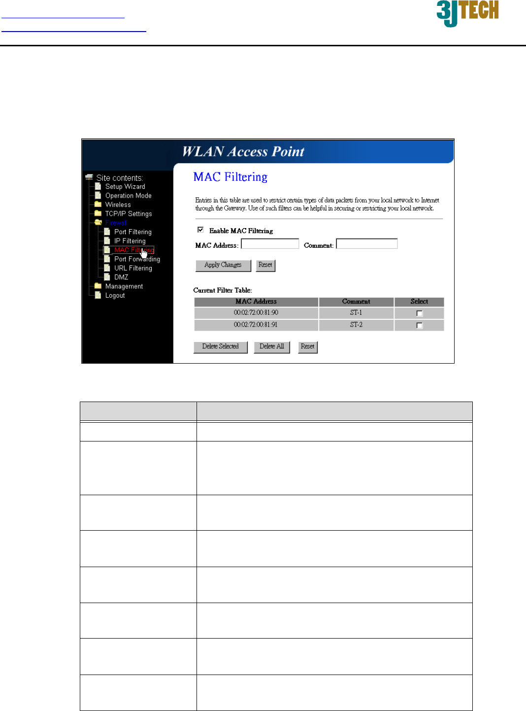
3.2.4.13 Firewall - MAC Filtering
Entries in this table are used to restrict certain types of data packets from your local network to
Internet through the Gateway. Use of such filters can be helpful in securing or restricting your local
network.
Fig. 3-21
Item Description
Enable MAC Filtering Click to enable the MAC filtering security function.
MAC Address To restrict data transmission from local network on
certain MAC addresses, fill in the MAC address and
your comments on it.
Comment Comment let you know about the reason to restrict
data from the MAC address.
Apply Changes Click the Apply Changes button to register the MAC
address to MAC filtering list.
Reset Click the Reset button to abort change and recover
the previous configuration setting.
Delete Selected Click to delete the selected MAC address that will be
removed from the MAC-filtering list.
Delete All Click to delete all the registered entries from the
MAC-filtering list.
Reset Click the Reset button to abort change and recover
the previous configuration setting.
http://www.3jtech.com.tw
http://www.pnpipcameras.com
DWR User’s Guide
Copyright of 3JTech Co., Ltd. (also doing business as A3J Engineering Inc.)
38
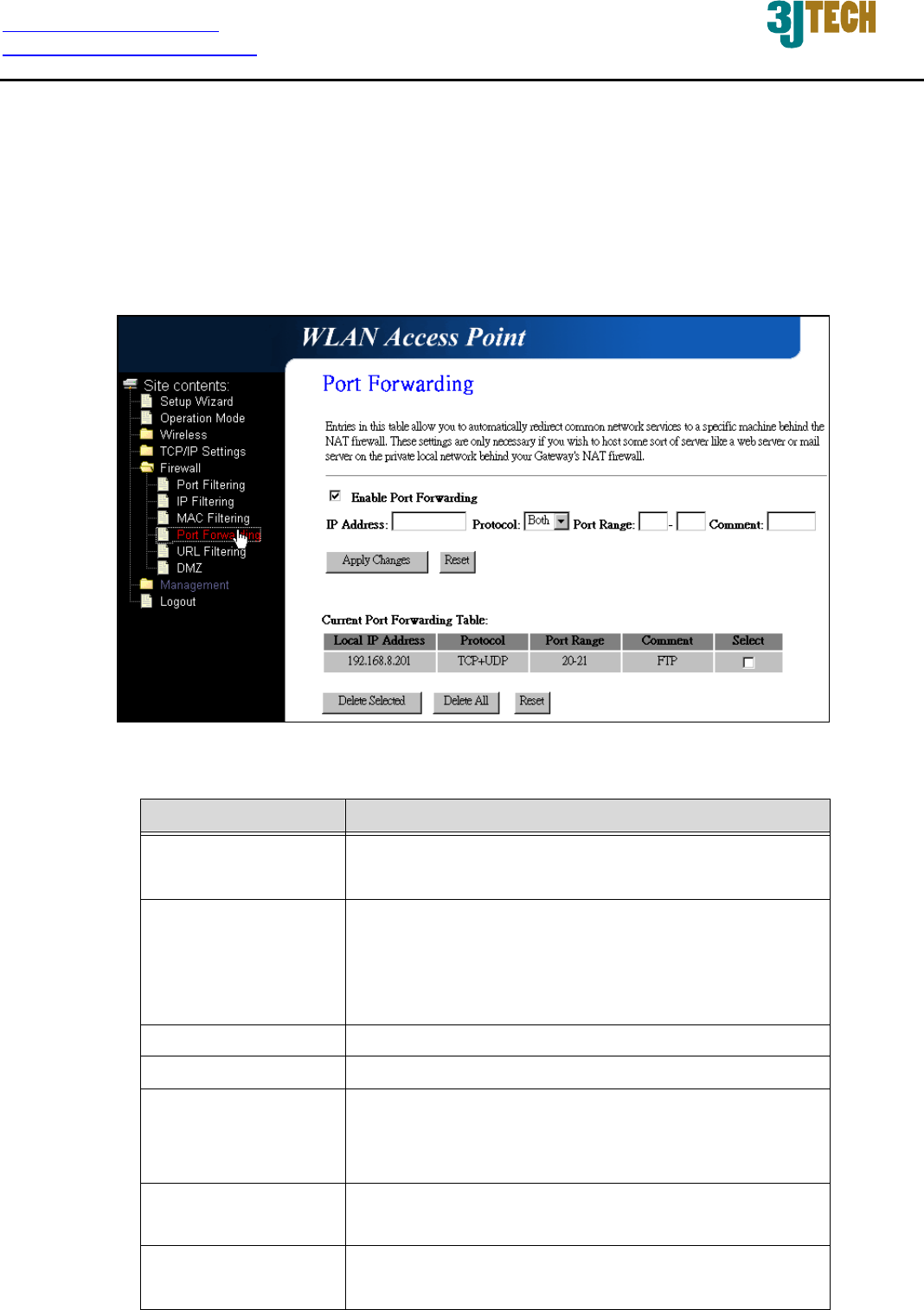
3.2.4.14 Firewall - Port Forwarding
Entries in this table allow you to automatically redirect common network services to a specific
machine behind the NAT firewall. These settings are only necessary if you wish to host some sort of
server like a web server or mail server on the private local network behind your Gateway's NAT
firewall.
Fig. 3-22
Item Description
Enable Port
Forwarding
Click to enable the Port Forwarding security
function.
IP Address To forward data packets coming from WAN to a
specific IP address that hosted in local network
behind the NAT firewall, fill in the IP address,
protocol, port range and your comments.
Protocol The Protocol can be TCP, UDP or Both.
Port Range The Port Range for data transmission.
Comment Comment let you know about the reason to allow
data packets forward to the IP address and port
number.
Apply Changes Click the Apply Changes button to register the IP
address and port number to Port forwarding list.
Reset Click the Reset button to abort change and recover
the previous configuration setting.
http://www.3jtech.com.tw
http://www.pnpipcameras.com
DWR User’s Guide
Copyright of 3JTech Co., Ltd. (also doing business as A3J Engineering Inc.)
39
Delete Selected Click to delete the selected IP address and port
number that will be removed from the
port-forwarding list.
Delete All Click to delete all the registered entries from the
port-forwarding list.
Reset Click the Reset button to abort change and recover
the previous configuration setting.
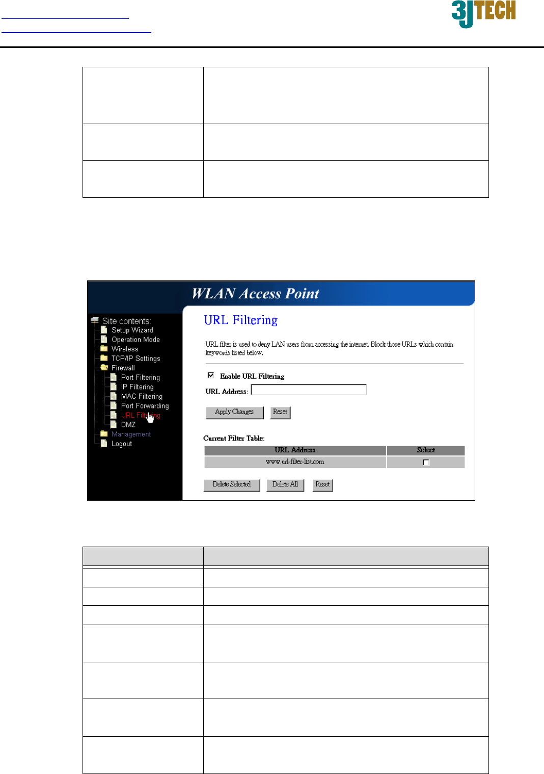
3.2.4.15 Firewall – URL Filtering
URL Filtering is used to restrict users to access specific websites in internet.
Fig. 3-23
Item Description
Enable URL Filtering Click to enable the URL Filtering function.
URL Address Add one URL address.
Apply Changes Click the Apply Changes button to save settings.
Reset Click the Reset button to abort change and recover
the previous configuration setting.
Delete Selected Click to delete the selected URL address that will be
removed from the URL Filtering list.
Delete All Click to delete all the registered entries from the
URL Filtering list.
Reset Click the Reset button to abort change and recover
the previous configuration setting.
http://www.3jtech.com.tw
http://www.pnpipcameras.com
DWR User’s Guide
Copyright of 3JTech Co., Ltd. (also doing business as A3J Engineering Inc.)
40
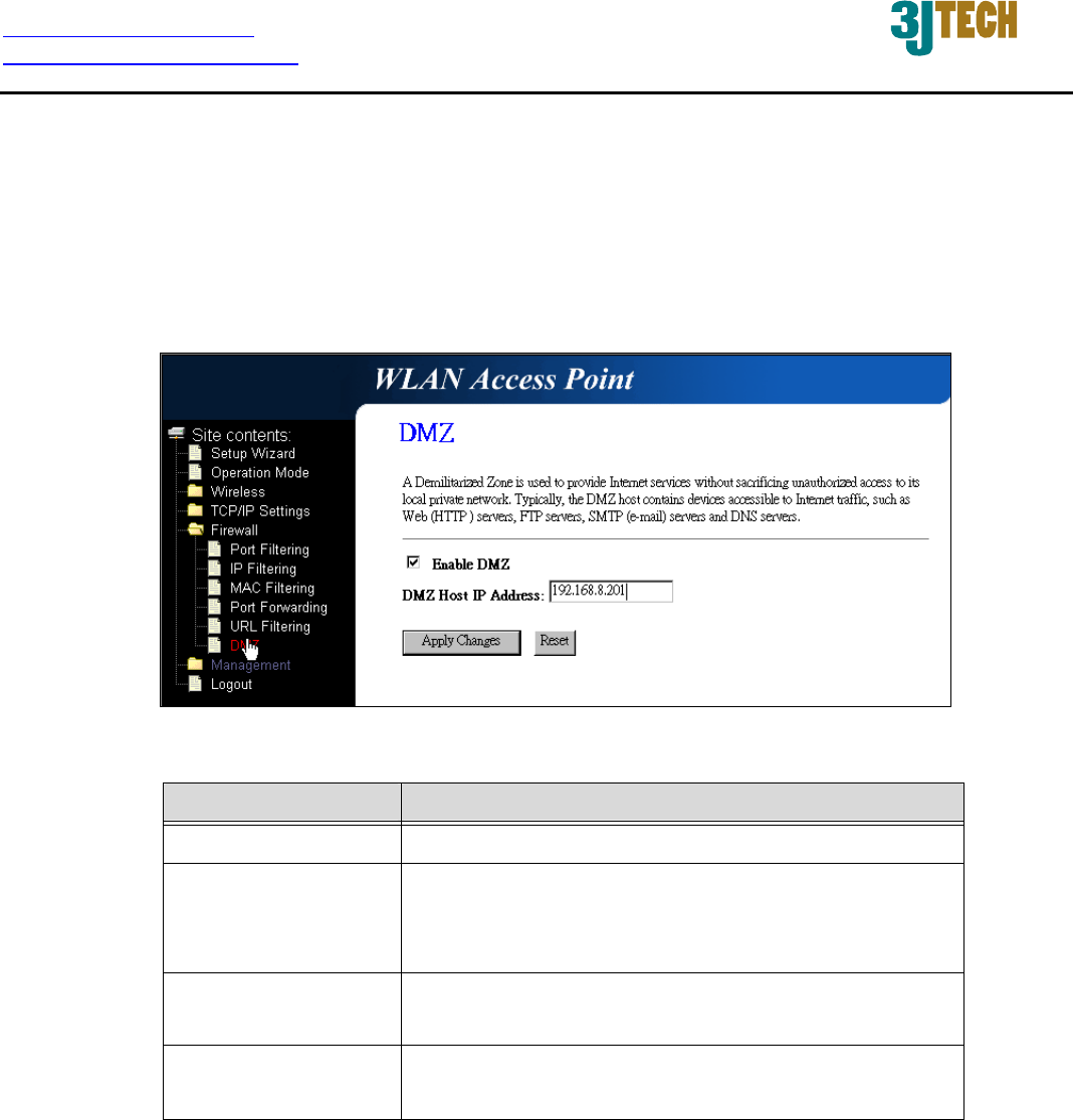
3.2.4.16 Firewall - DMZ
A Demilitarized Zone is used to provide Internet services without sacrificing unauthorized access to
its local private network. Typically, the DMZ host contains devices accessible to Internet traffic, such
as Web (HTTP) servers, FTP servers, SMTP (e-mail) servers and DNS servers.
Fig. 3-24
Item Description
Enable DMZ Click to enable the DMZ function.
DMZ Host IP Address To support DMZ in your firewall design, fill in the IP
address of DMZ host that can be access from the
WAN interface.
Apply Changes Click the Apply Changes button to register the IP
address of DMZ host.
Reset Click the Reset button to abort change and recover
the previous configuration setting.
http://www.3jtech.com.tw
http://www.pnpipcameras.com
DWR User’s Guide
Copyright of 3JTech Co., Ltd. (also doing business as A3J Engineering Inc.)
41
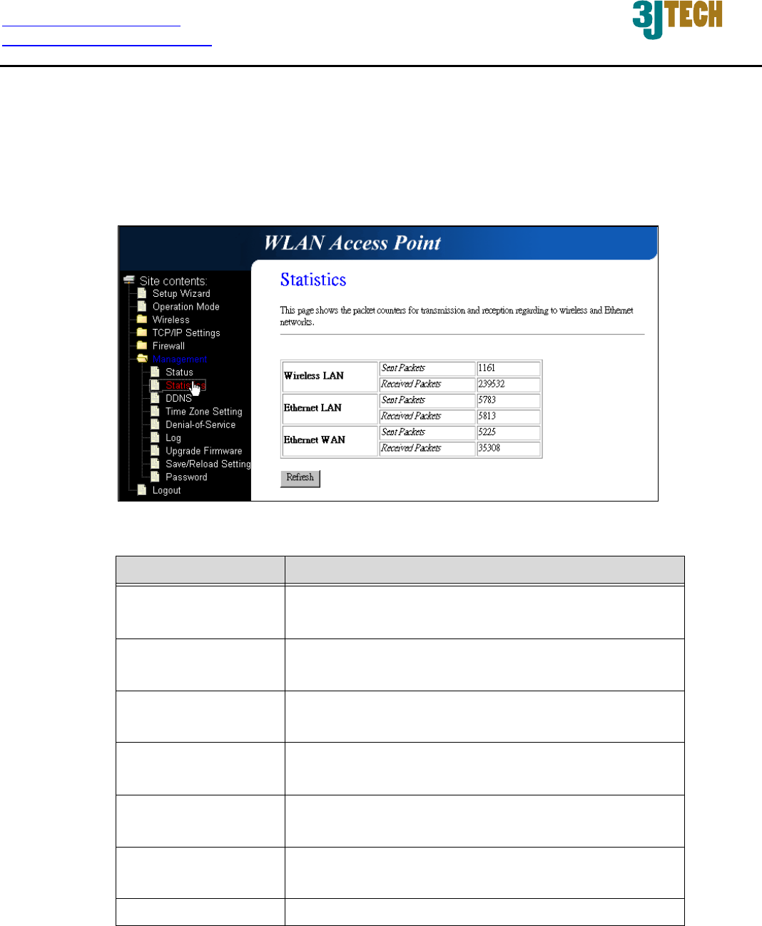
3.2.4.17 Management - Statistics
This page shows the packet counters for transmission and reception regarding to wireless, Ethernet
LAN and Ethernet WAN networks.
Fig. 3-25
Item Description
Wireless LAN
Sent Packets
It shows the statistic count of sent packets on the
wireless LAN interface.
Wireless LAN
Received Packets
It shows the statistic count of received packets on
the wireless LAN interface.
Ethernet LAN
Sent Packets
It shows the statistic count of sent packets on the
Ethernet LAN interface.
Ethernet LAN
Received Packets
It shows the statistic count of received packets on
the Ethernet LAN interface.
Ethernet WAN
Sent Packets
It shows the statistic count of sent packets on the
Ethernet WAN interface.
Ethernet WAN
Received Packets
It shows the statistic count of received packets on
the Ethernet WAN interface.
Refresh Click the refresh the statistic counters on the screen.
http://www.3jtech.com.tw
http://www.pnpipcameras.com
DWR User’s Guide
Copyright of 3JTech Co., Ltd. (also doing business as A3J Engineering Inc.)
42
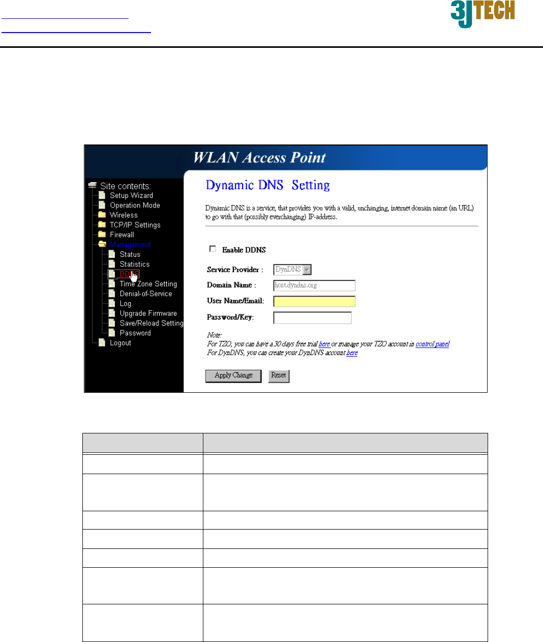
3.2.4.18 Management - DDNS
This page is used to configure Dynamic DNS service to have DNS with dynamic IP address.
Fig. 3-26
Item Description
Enable DDNS Click the checkbox to enable DDNS service.
Service Provider Click the drop down menu to pickup the right
provider.
Domain Name To configure the Domain Name.
User Name/Email Configure User Name, Email.
Password/Key Configure Password, Key.
Apply Change Click the Apply Changes button to save the enable
DDNS service.
Reset Click the Reset button to abort change and recover
the previous configuration setting.
http://www.3jtech.com.tw
http://www.pnpipcameras.com
DWR User’s Guide
Copyright of 3JTech Co., Ltd. (also doing business as A3J Engineering Inc.)
43
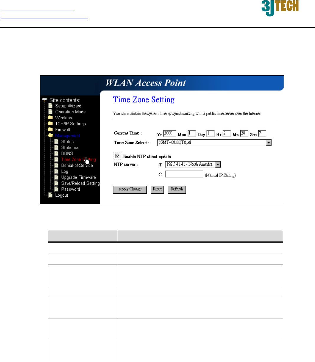
3.2.4.19 Management - Time Zone Setting
This page is used to configure NTP client to get current time.
Fig. 3-27
Item Description
Current Time It shows the current time.
Time Zone Select Click the time zone in your country.
Enable NTP client
update
Click the checkbox to enable NTP client update.
NTP Server Click select default or input NTP server IP address.
Apply Change Click the Apply Changes button to save and enable
NTP client service.
Reset Click the Reset button to abort change and recover
the previous configuration setting.
Refresh Click the refresh the current time shown on the
screen.
http://www.3jtech.com.tw
http://www.pnpipcameras.com
DWR User’s Guide
Copyright of 3JTech Co., Ltd. (also doing business as A3J Engineering Inc.)
44
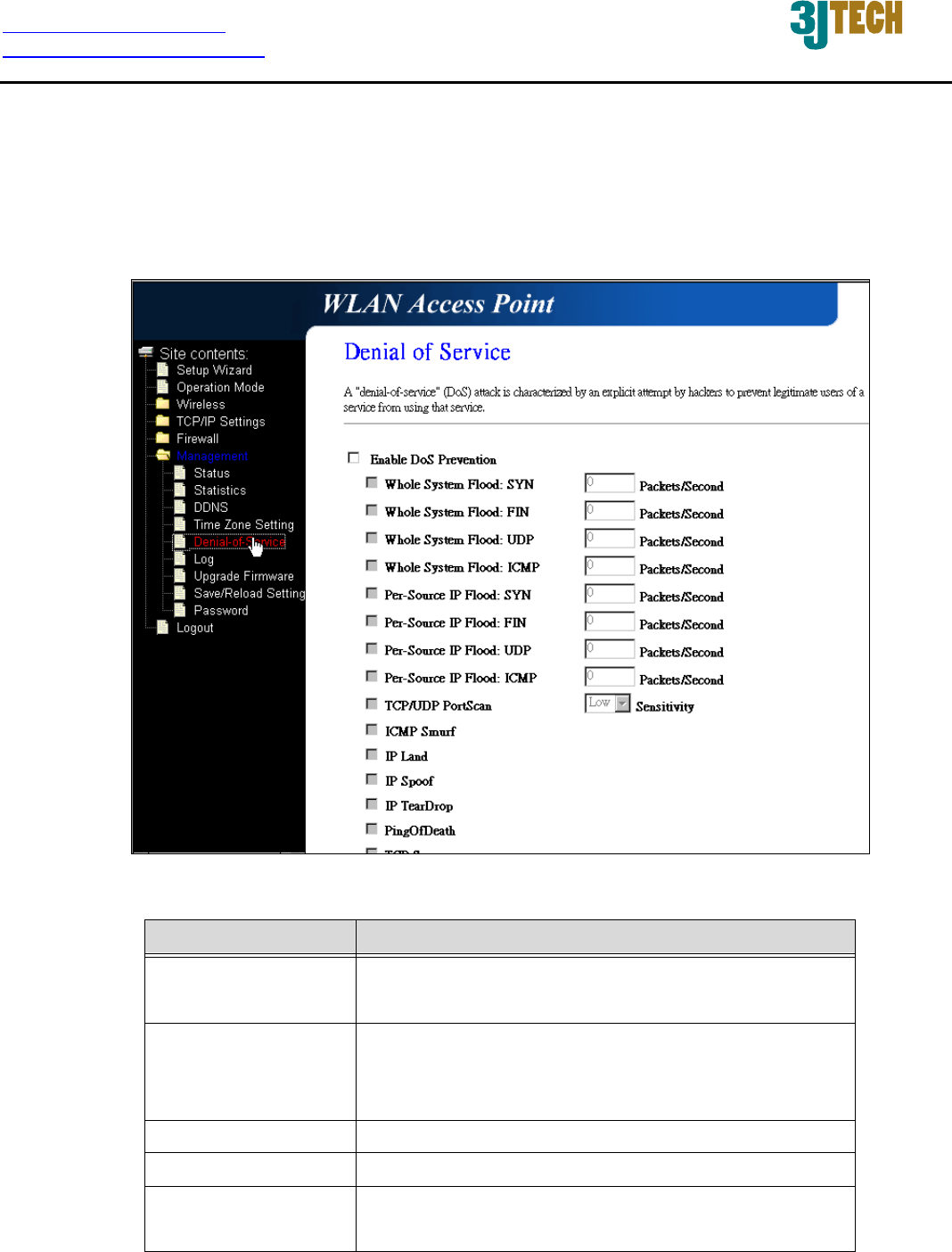
3.2.4.20 Management – Denial-of-Service
This page is used to enable and setup protection to prevent attack by hacker’s program. It provides
more security for users.
Fig. 3-28
Item Description
Enable DoS
Prevention
Click the checkbox to enable DoS prevention
function.
Whole System Flood
/ Per-Source IP
Flood…
Enable and set up prevention in details.
Select ALL Click the checkbox to enable all prevention items.
Clear ALL Click the checkbox to disable all prevention items.
Apply Changes Click the Apply Changes button to save above
settings.
http://www.3jtech.com.tw
http://www.pnpipcameras.com
DWR User’s Guide
Copyright of 3JTech Co., Ltd. (also doing business as A3J Engineering Inc.)
45
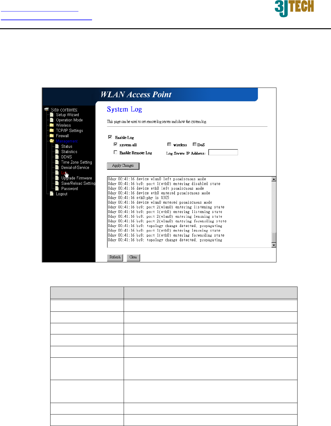
3.2.4.21 Management - Log
This page is used to configure the remote log server and show the current log.
Fig. 3-29
Item Description
Enable Log Click the checkbox to enable log.
System all Show all log of DWR.
Wireless Only show wireless log.
DoS Only show Denial-of-Service log.
Enable Remote Log Click the checkbox to enable remote log service.
Log Server IP
Address
Input the remote log IP address.
Apply Changes Click the Apply Changes button to save above
settings.
Refresh Click the refresh the log shown on the screen.
Clear Clear log display screen.
http://www.3jtech.com.tw
http://www.pnpipcameras.com
DWR User’s Guide
Copyright of 3JTech Co., Ltd. (also doing business as A3J Engineering Inc.)
46
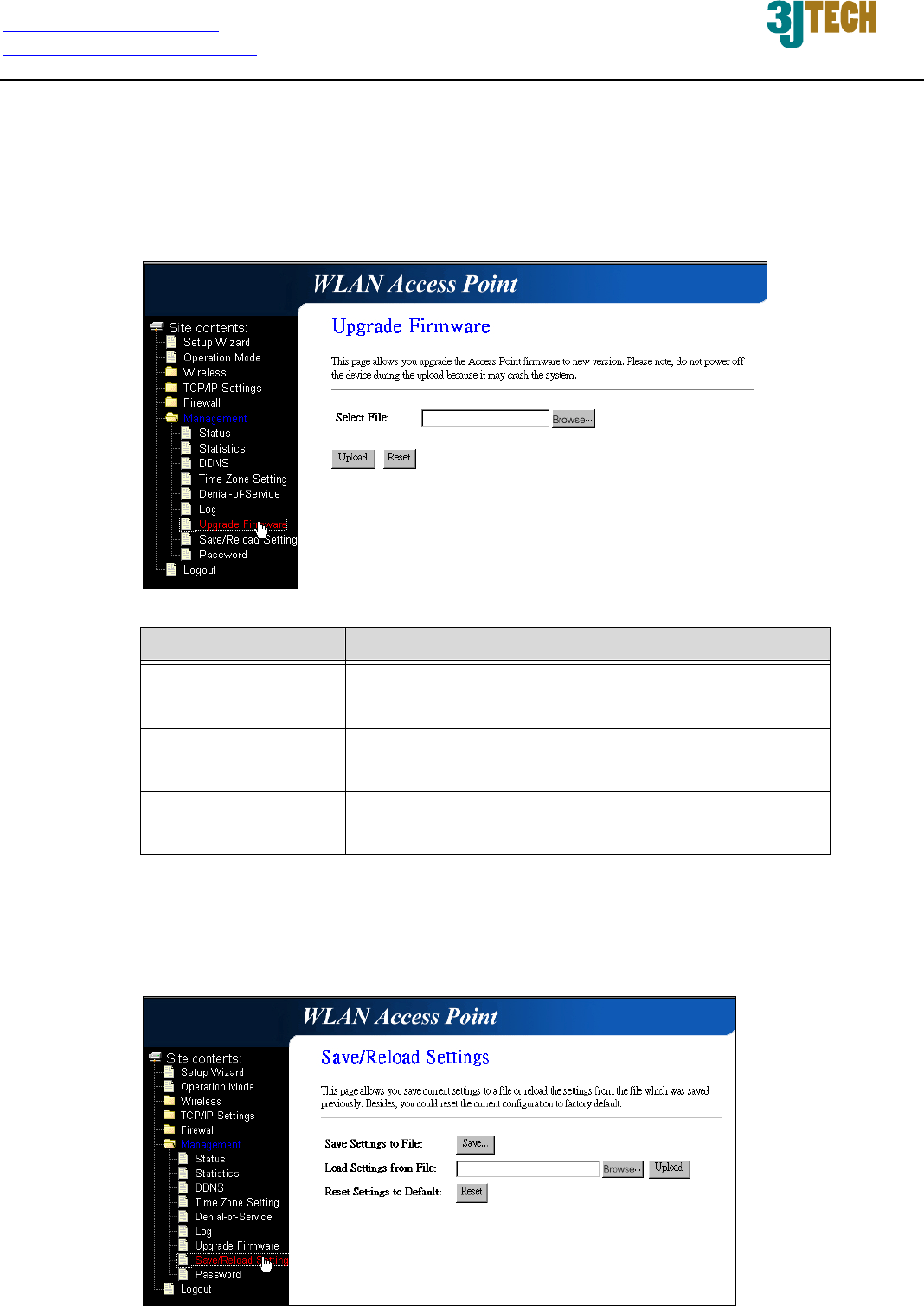
3.2.4.22 Management - Upgrade Firmware
This page allows you upgrade the Access Point firmware to new version. Please note, do not power
off the device during the upload because it may crash the system.
Fig. 3-30
Item Description
Select File Click the Browse… button to select the new version
of web firmware image file.
Upload Click the Upload button to update the selected web
firmware image to DWR.
Reset Click the Reset button to abort change and recover
the previous configuration setting.
3.2.4.23 Management - Save/ Reload Settings
This page allows you save current settings to a file or reload the settings from the file that was saved
previously. Besides, you could reset the current configuration to factory default.
Fig. 3-31
http://www.3jtech.com.tw
http://www.pnpipcameras.com
DWR User’s Guide
Copyright of 3JTech Co., Ltd. (also doing business as A3J Engineering Inc.)
47
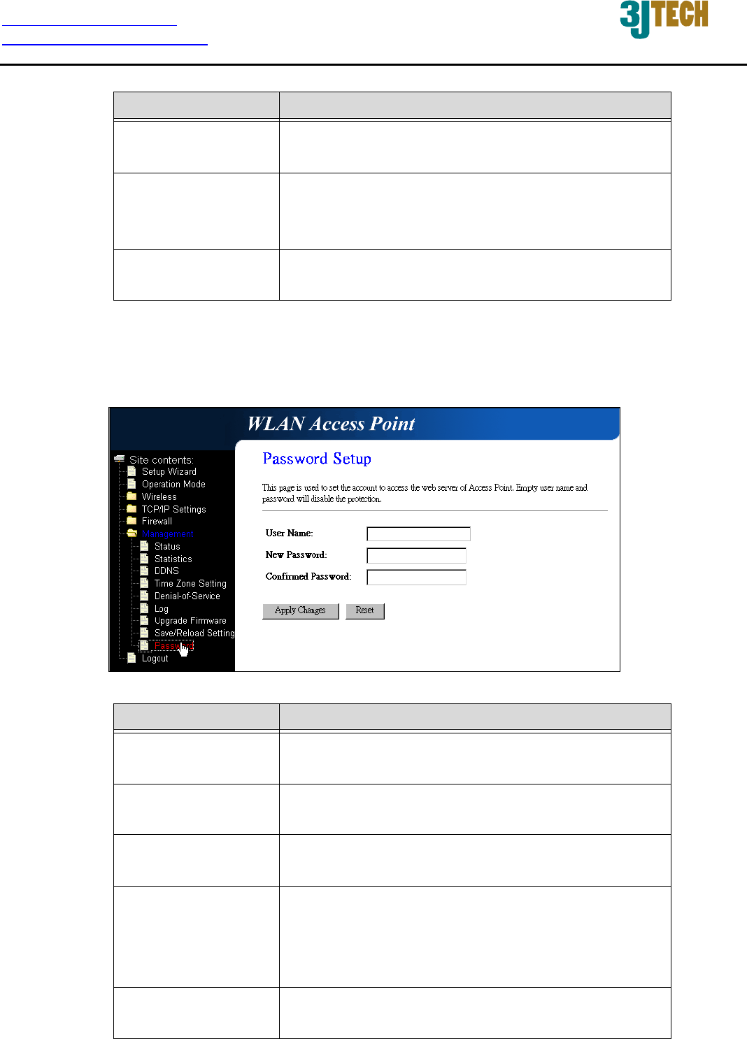
Item Description
Save Settings to File Click the Save button to download the configuration
parameters to your personal computer.
Load Settings from
File
Click the Browse… button to select the
configuration files then click the Upload button to
update the selected configuration to DWR.
Reset Settings to
Default
Click the Reset button to reset the configuration
parameter to factory defaults.
3.2.4.24 Management - Password Setup
This page is used to set the account to access the web server of Access Point. Empty user name
and password will disable the protection.
Fig. 3-32
Item Description
User Name Fill in the user name for web management login
control.
New Password Fill in the password for web management login
control.
Confirmed Password Because the password input is invisible, so please
fill in the password again for confirmation purpose.
Apply Changes Clear the User Name and Password fields to
empty, means to apply no web management login
control. Click the Apply Changes button to
complete the new configuration setting.
Reset Click the Reset button to abort change and recover
the previous configuration setting.
http://www.3jtech.com.tw
http://www.pnpipcameras.com
DWR User’s Guide
Copyright of 3JTech Co., Ltd. (also doing business as A3J Engineering Inc.)
48
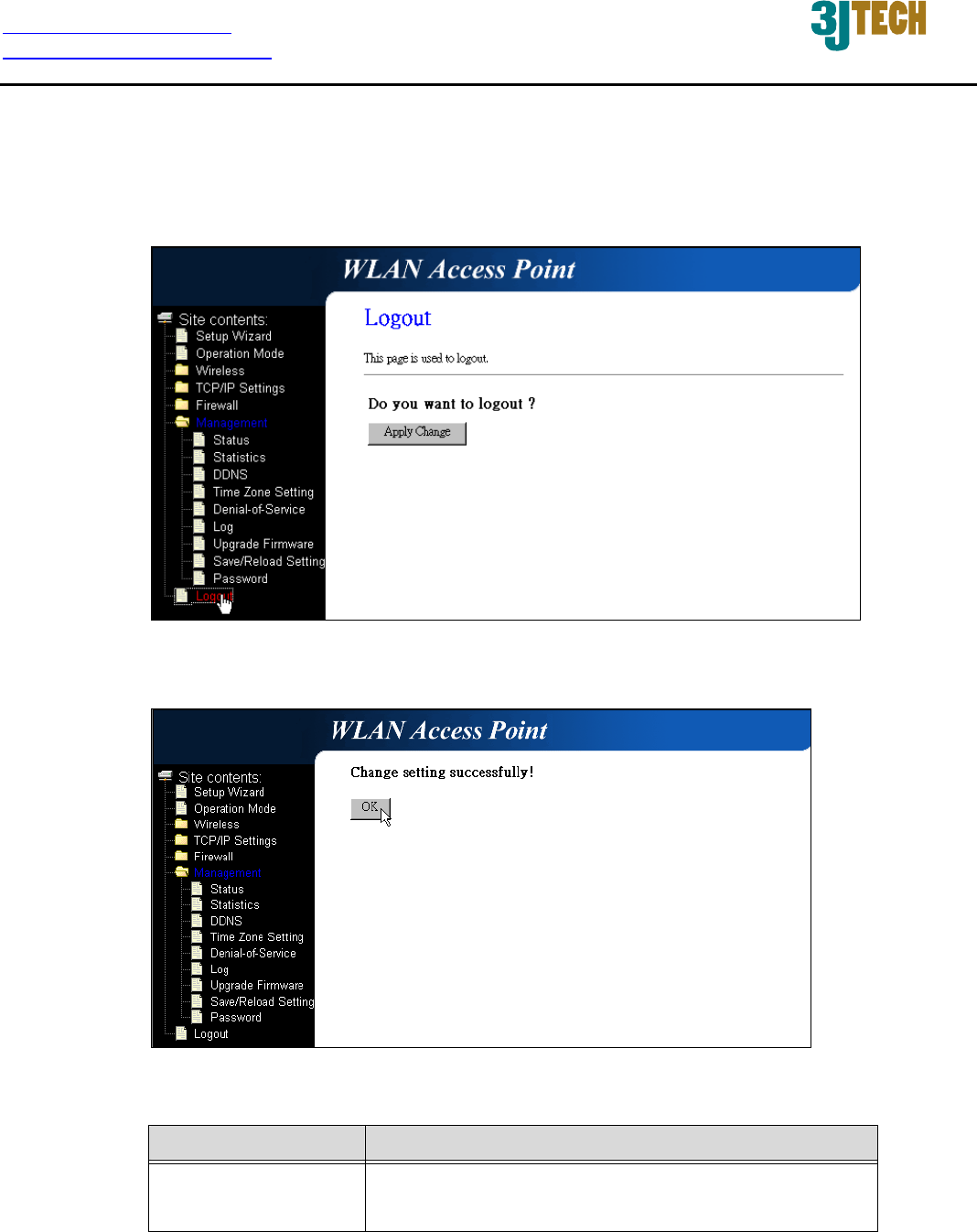
3.2.4.25 Logout
This page is used to logout web management page. This item will be activated next time you login
after you define user account and password.
Fig. 3-33
Fig. 3-34
Item Description
Apply Change Click the Apply Change button, Then click OK
button to logout.

Federal Communication Commission Interference Statement
This equipment has been tested and found to comply with the limits for a Class B digital device,
pursuant to Part 15 of the FCC Rules. These limits are designed to provide reasonable protection
against harmful interference in a residential installation.
This equipment generates, uses and can radiate radio frequency energy and, if not installed and
used in accordance with the instructions, may cause harmful interference to radio
communications. However, there is no guarantee that interference will not occur in a particular
installation. If this equipment does cause harmful interference to radio or television reception,
which can be determined by turning the equipment off and on, the user is encouraged to try to
correct the interference by one of the following measures:
. Reorient or relocate the receiving antenna.
. Increase the separation between the equipment and receiver.
. Connect the equipment into an outlet on a circuit different from that to which the receiver is
connected.
. Consult the dealer or an experienced radio/TV technician for help.
FCC Caution: To assure continued compliance, any changes or modifications not expressly
approved by the party responsible for compliance could void the user's authority to operate this
equipment. (Example - use only shielded interface cables when connecting to computer or
peripheral devices).
This device complies with Part 15 of the FCC Rules. Operation is subject to the following two
conditions:
(1) This device may not cause harmful interference, and (2) This device must accept any
interference received, including interference that may cause undesired operation.
FCC Radiation Exposure Statement
This equipment complies with FCC RF radiation exposure limits set forth for an uncontrolled
environment. This equipment should be installed and operated with a minimum distance of 20
centimeters between the radiator and your body.
This transmitter must not be co-located or operating in conjunction with any other antenna or
transmitter.
The antennas used for this transmitter must be installed to provide a separation distance of at
least 20 cm from all persons and must not be co-located or operating in conjunction with any other
antenna or transmitter.