3M Scott Technologies 200729 SEMS II Unit User Manual 595166 01 A
Scott Safety-Division of Scott Technologies, Inc. SEMS II Unit 595166 01 A
UserManual.wiki
>
3M Scott Technologies
>
200729 User Manual
Users Manual
Navigation menu
Upload a User Manual
Namespaces
Wiki Guide
HTML
PDF
Info
Views
User Manual
Discussion / Help
Navigation


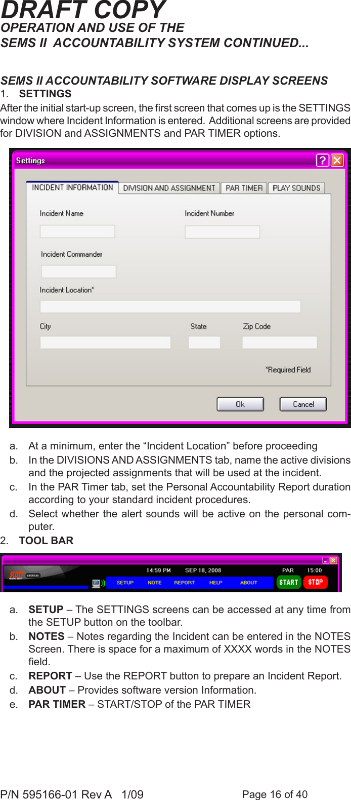
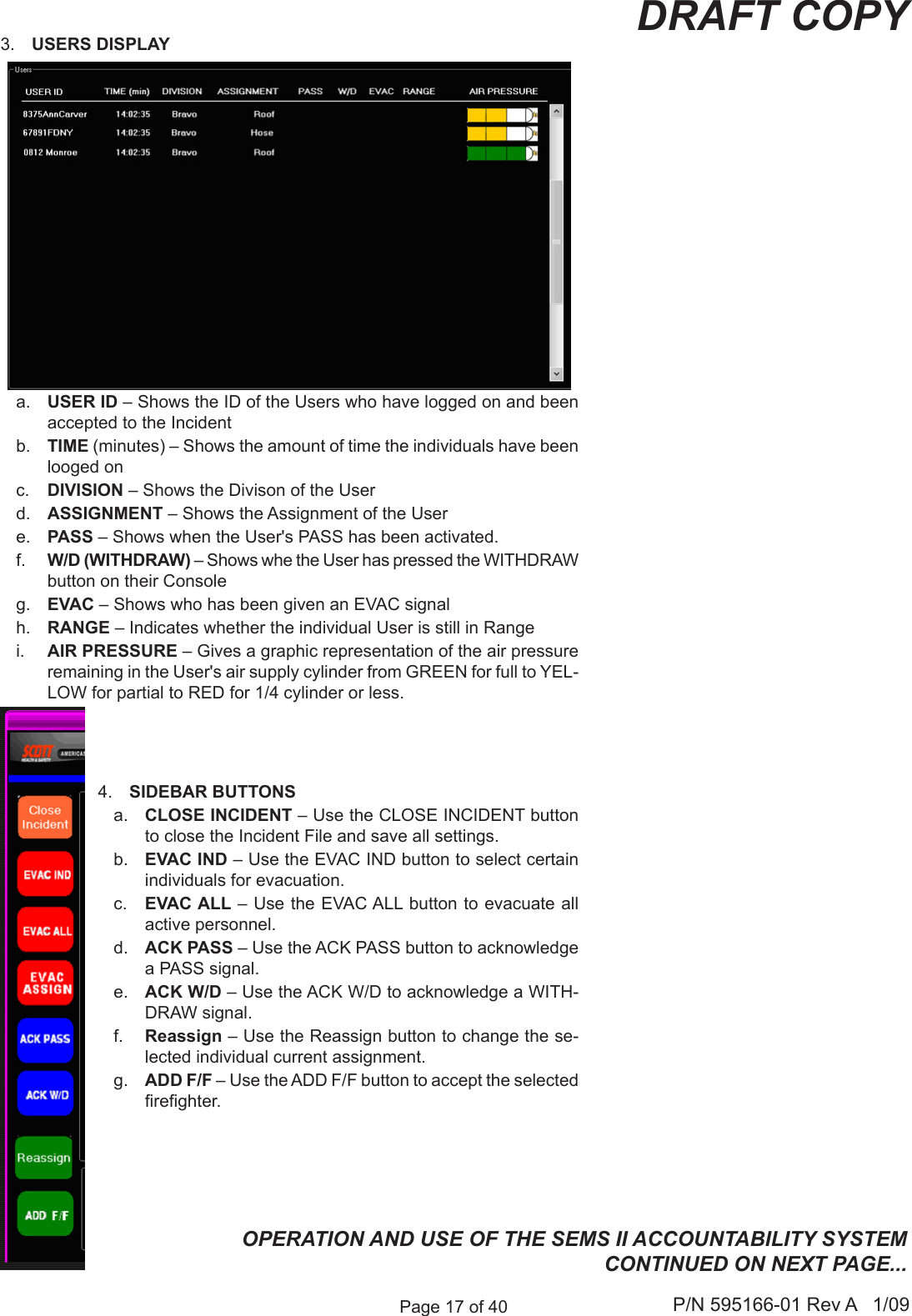
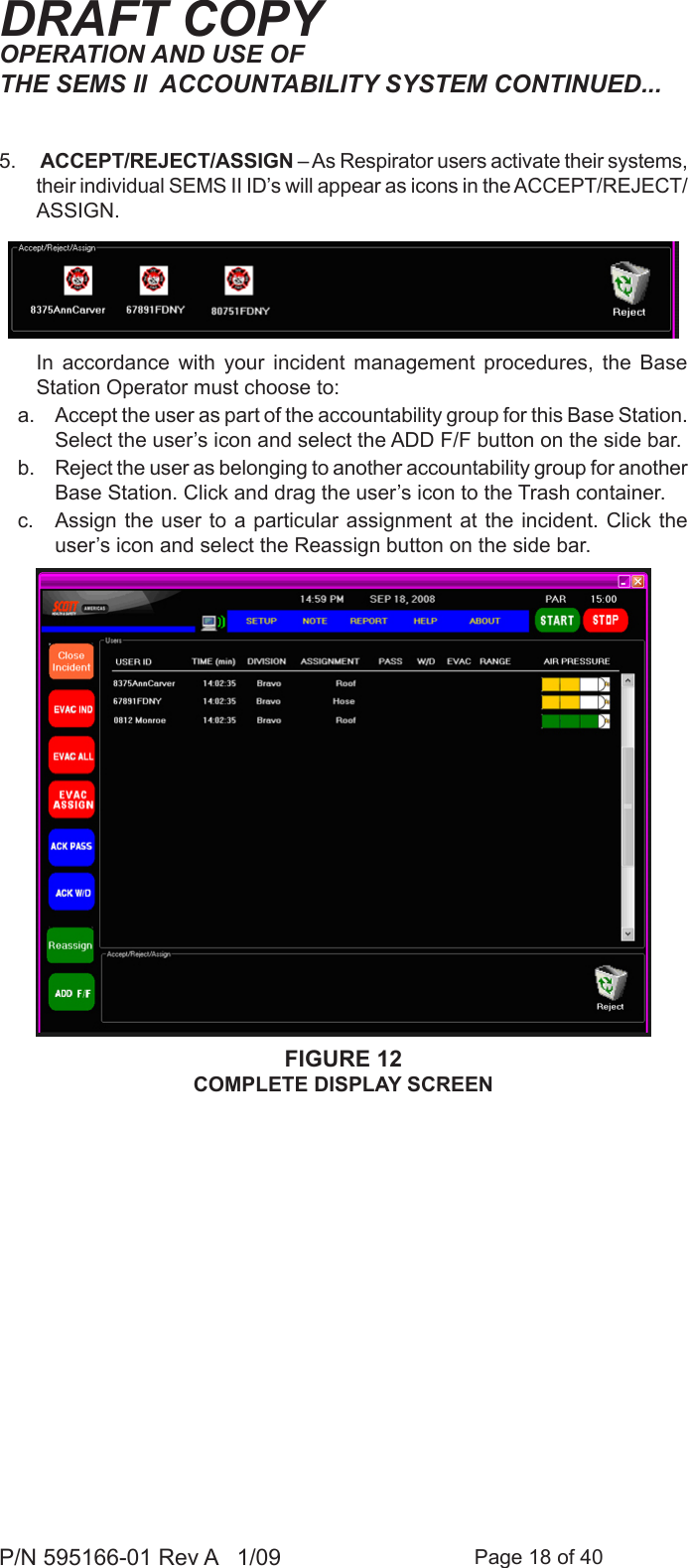


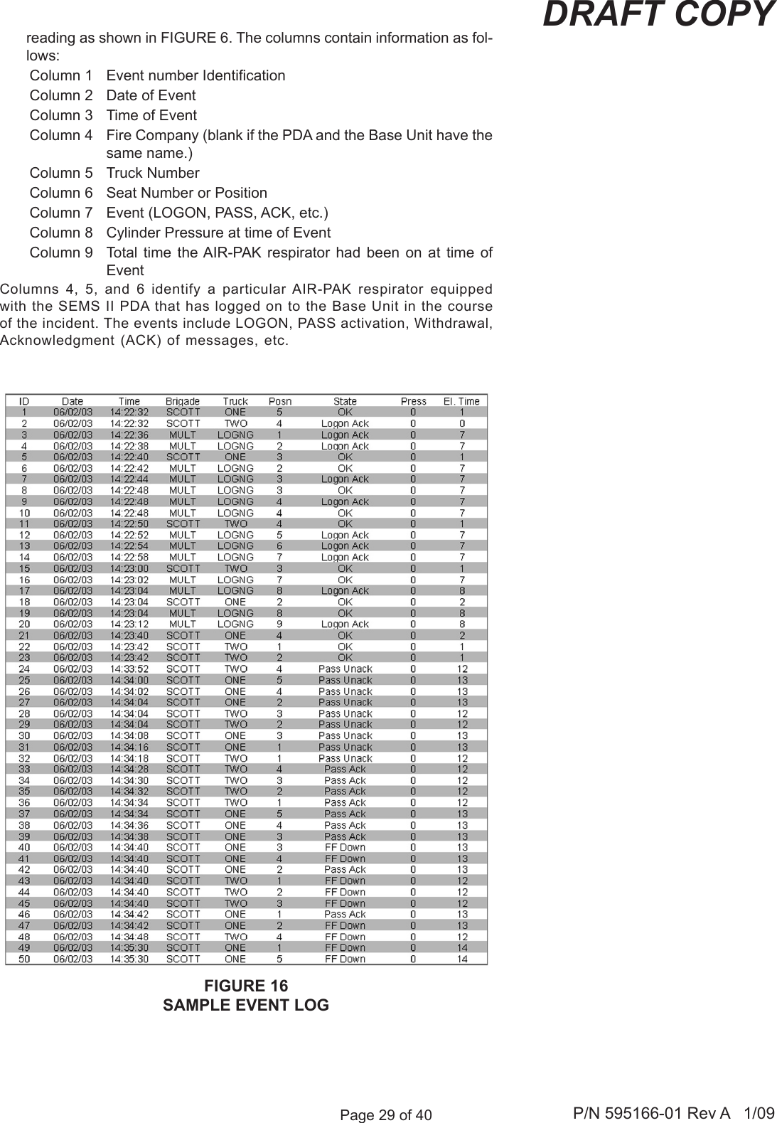
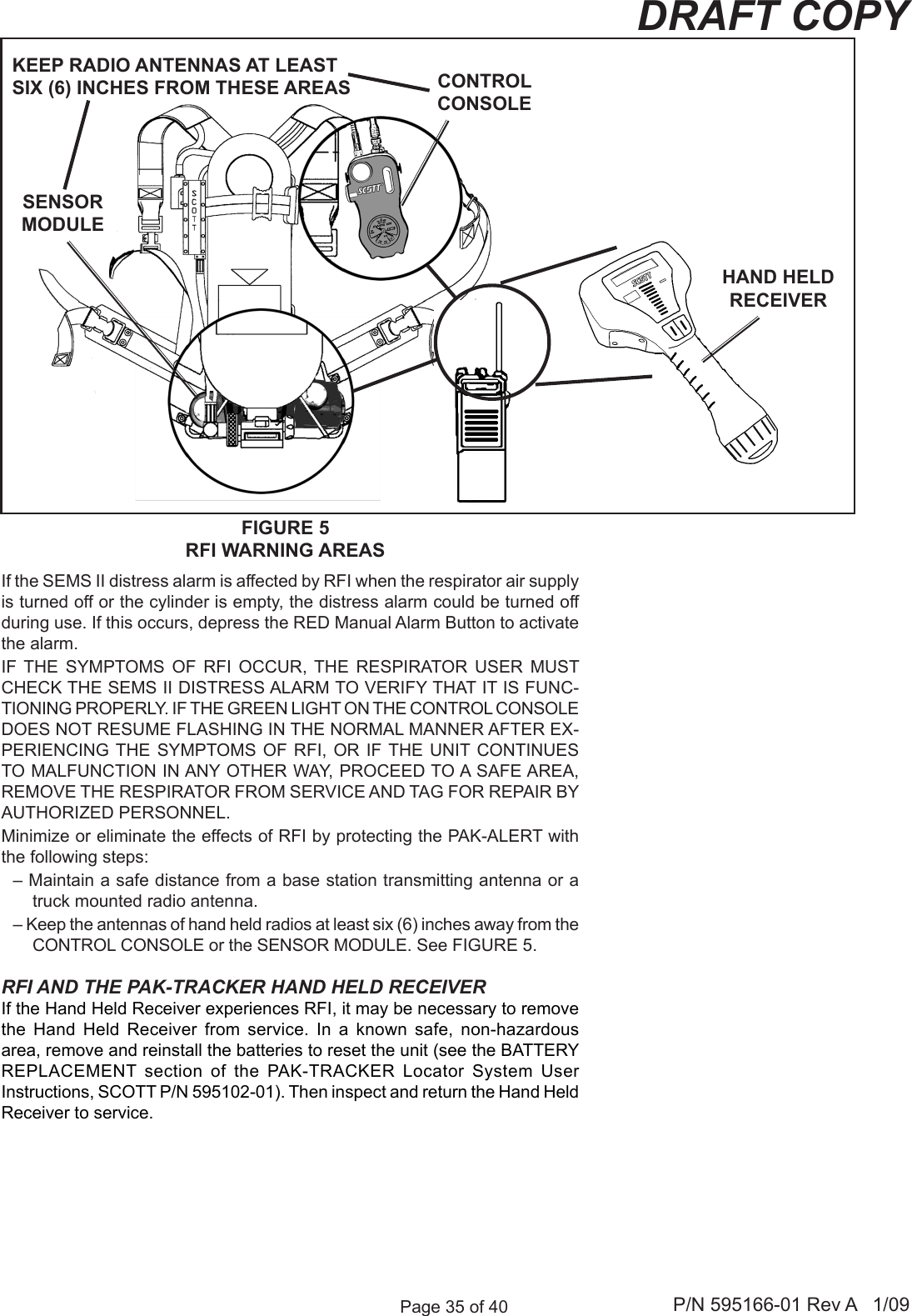
![Page 28 of 40P/N 595166-01 Rev A 1/09DRAFT COPYFIGURE 15EVENT LOG SCREENEVENT LOGSoftware within the Base Station maintains a data record or EVENT LOG of each communication to or from the Base Station from the time it is powered for use until it is powered down. To access and use the EVENT LOG, proceed as follows:BASE UNIT INTERFACE SETUPPlug the Base Unit Interface Cable into a COM port as instructed in the COMPUTER SETUP section the SEMS II Programming Instructions SCOTT P/N 89506-01. 1. Plug the other end of the Base Unit Interface Cable into the connector on the side of the Base Unit.2. Run the SEMS II Fire Department Software and select the tab labeled “EVENT LOG.” See FIGURE 5.3. On the Base Unit, press and hold the EVAC button while turning on the unit by pressing the POWER ON/OF button. Continue holding the EVAC button until the screen displays, “COMMAND MODE: CS =0X2A58”. (NOTE: CS number may vary depending on version of Base Unit.)4. Choose either “SAVE” or “SAVE & PURGE” to save the information in the EVENT LOG. The data will be saved as a text (.txt) le to a folder called “Event Logs” in the same folder where the SEMS II Fire Department Software resides on your computer [e.g.:(drive)\Program Files\SEMS II Service Center\Event Logs\(folder)].a) “SAVE” will save the EVENT LOG le to the Event Logs folder but leaves the EVENT LOG information on the Base Unit.b) “SAVE & PURGE” will save the EVENT LOG le to the Event Logs folder and then erase the EVENT LOG information from the Base Unit.5. The EVENT LOG le is a text (.txt) which may be viewed in either Microsoft Excel or Microsoft Word. The data is in columns separated (delimited) by commas. It may require some manipulation of the columns to facilitate](https://usermanual.wiki/3M-Scott-Technologies/200729/User-Guide-1110601-Page-28.png)