3M Scott Technologies 200729 SEMS II Unit User Manual 595166 01 A
Scott Safety-Division of Scott Technologies, Inc. SEMS II Unit 595166 01 A
Users Manual

Page 1 of 40 P/N 595166-01 Rev A 1/09
DRAFT COPY
Copyright © 2009, SCOTT, All Rights Reserved
SEMS® II
SCOTT ELECTRONIC MANAGEMENT SYSTEM
PERSONAL DISTRESS ALARM AND BASE STATION
USER ACCOUNTABILITY SYSTEM, PERSONAL DISTRESS ALARM,
AND SCOTT PAK-TRACKER LOCATOR SYSTEM
FOR THE SCOTT SELF-CONTAINED BREATHING APPARATUS
SEMS II BASE STATION PCMCIA CARD
(SHOWN WITH REQUIRED LAPTOP COMPUTER,
NOT INCLUDED)
SEMS® II CONSOLE
WARNING
THE SCOTT SEMS II USER ACCOUNTABILITY SYSTEM IS INTENDED FOR USE WITH SCOTT
SELF-CONTAINED BREATHING APPARATUS (SCBA) WHICH MAY SUPPORT HUMAN LIFE
IN HAZARDOUS ATMOSPHERES. FAILURE TO CAREFULLY READ AND UNDERSTAND
THE FOLLOWING INSTRUCTIONS MAY RESULT IN SERIOUS INJURY OR DEATH TO
THE SCBA USER.
USE OF A RESPIRATOR INTEGRATED WITH THE SEMS II USER ACCOUNTABILITY SYS-
TEM WILL REQUIRE MODIFICATION OF THE RESPIRATOR "REGULAR OPERA-
TIONAL INSPECTION PROCEDURES" AND WILL REQUIRE TRAINING OF THE RESPIRATOR
USER IN THE USE OF SUCH RESPIRATORS.
THE FOLLOWING INSTRUCTIONS SUPPLEMENT BUT DO NOT REPLACE THE OPERATING
AND MAINTENANCE INSTRUCTIONS SUPPLIED WITH EACH RESPIRATOR.
OPERATION AND MAINTENANCE INSTRUCTIONS
Page 2 of 40
P/N 595166-01 Rev A 1/09
DRAFT COPY
1 Kevlar is a registered trademark of E. I. Du Pont
de Nemours, Inc.
WARNING
NO PERSONAL ALERT SAFETY SYSTEM, RES-
PIRATOR OR COMBINATION OF PERSONAL
ALERT SAFETY SYSTEM AND RESPIRATOR,
BY THEMSELVES, CAN PROVIDE COMPLETE
PROTECTION IN DANGEROUS SITUATIONS.
FAILURE TO FOLLOW THE INSTRUCTIONS
IN THIS MANUAL AND THE REQUIREMENTS
OF AN ORGANIZED RESPIRATORY PROTEC-
TION PROGRAM MAY LEAD TO SITUATIONS
WHICH COULD RESULT IN SERIOUS INJURY
OR DEATH.
WARNING
USERS OF RESPIRATORS EQUIPPED WITH THE
SEMS II DISTRESS ALARM MUST BE AWARE OF
THE PROPER OPERATION OF THE DISTRESS
ALARM. IF THE GREEN LIGHT IS NOT FLASH-
ING NORMALLY, OR IF THE UNIT EXHIBITS ANY
OTHER SIGNS OF A MALFUNCTION WITHOUT
THE USER TAKING PROPER CORRECTIVE AC-
TION, IT MAY LEAD TO CIRCUMSTANCES THAT
RESULT IN SERIOUS INJURY OR DEATH.
WARNING
DO NOT OPERATE THIS EQUIPMENT WHILE UN-
DER THE INFLUENCE OF DRUGS, ALCOHOL, OR
ANY MEDICATIONS OR SUBSTANCES WHICH
MAY AFFECT VISION, DEXTERITY, OR JUDG-
MENT. USERS OF THIS EQUIPMENT MUST BE
IN GOOD PHYSICAL AND MENTAL HEALTH IN
ORDER TO OPERATE SAFELY. DO NOT USE THIS
EQUIPMENT WHEN FATIGUE PREVENTS SAFE
OPERATION. STAY ALERT WHEN OPERATING
THIS EQUIPMENT. INATTENTION OR CARELESS-
NESS WHILE OPERATING THIS EQUIPMENT MAY
RESULT IN SERIOUS INJURY OR DEATH.
WARNING
FOLLOW REGULAR OPERATIONAL INSPEC-
TION PROCEDURE EXACTLY. IF THE SEMS II
DISTRESS ALARM DOES NOT ACTUATE, OR IF
ANY OTHER FEATURE DOES NOT OPERATE AS
DESCRIBED OR IF ANY OTHER OPERATIONAL
MALFUNCTION IS NOTED, DO NOT USE THE
RESPIRATOR.
SYSTEM DESCRIPTION
SEMS II ACCOUNTABILITY SYSTEM
The SCOTT Electronic Management System (SEMS II) is an accountability
system that provides three methods of communication between respirator
users in a hazardous area and an incident commander or other designated
person outside of the hazardous area. The SCOTT SEMS II Personal Distress
Alarm (PDA) is an optional accessory which is intended to be integrated only
with a compatible SCOTT self-contained breathing apparatus (SCBA) such
as the AIR-PAK® SCBA. The installation of the SCOTT SEMS II PDA distress
alarm is approved by the National Institute of Occupational Safety and Health
(NIOSH) on specic models of SCOTT SCBA.
The complete system provides three main functions:
• The SEMS II Personal Alert Safety System (PASS) on the SCBA to
sound a loud alarm when the user is motionless for a short period of
time;
• The SEMS II Accountability System with computer Base Station monitor-
ing of the assignment and status of up to 99 individual users, including
air supply levels, PASS activation, and evacuation calls;
• The PAK-TRACKER Locator System to locate the transmitted signal
from a SEMS II PDA Portable Unit where the PASS has been acti-
vated.
The complete SEMS II Accountability System equipment consists of:
• Individual SEMS II PDA Portable Units with Control Console attached
to the SCOTT self-contained breathing apparatus;
• A SEMS II Personal Distress Receiver (PDR) Base Station (the Base
Station PCMCIA Card and the SCOTT SEMS II Accountability System
Software installed in a Personal Computer);
• Programmable ID Tags and programming equipment;
• A PAK-TRACKER Hand Held Receiver for search and rescue.
The PDA Portable Units can transmit and receive specic information between
the respirator users and the Base Station operator. The specic information
consists of user identication and status as well as alerts for evacuation.
Complete training in the use of the SEMS II equipment is required before
actual use in a hazardous environment.
When logged on, all the SEMS II PDA Portable Units communicate to the
Base Station both directly and through other logged on units forming a com-
munications "mesh" to the Base Station. This extends the range for the units
furthest away from the Base Station.
No personal alert safety system, respirator, or combination of personal alert
safety system and respirator, by themselves, can provide complete protec-
tion in dangerous situations. However, using an alarm and a respirator in
acordance with the requirements of an organized respiratory protection pro-
gram is one of the many safety precautions which should be taken to avoid
personal injury or death.
These instructions explain the operation and use of the main functions of the
SCOTT SEMS II Accountability System. Follow the REGULAR OPERATIONAL
INSPECTION procedure as described. If any function fails to operate as
described, do not use the equipment. Remove the unit from service and tag
for repair by authorized personnel.
Page 3 of 40 P/N 595166-01 Rev A 1/09
DRAFT COPY
SEMS II PDR BASE STATION
The SEMS II PDR Base Station consists of a SEMS II Accountability System
Base Station PCMCIA Card installed in a Windows® based Personal Com-
puter, preferably a laptop (not included). SCOTT recommends use of a laptop
computer designed for rugged use.
With the SEMS II Accountability Software running on the PC, the incident
commander has current information about status of the respirator users who
are logged onto the Base Station, including information about air supply lev-
els and PASS activation. Simple dedicated functions in the software control
the transmission and receipt of signals with the respirator users. The same
computer can be used for programming the ID Tags used with the SEMS II
PDA distress alarm.
SYSTEM DESCRIPTION
CONTINUED ON NEXT PAGE...
FIGURE 2
SEMS II BASE STATION PCMCIA CARD INSTALLED IN
A PANASONIC1 TOUGHBOOK2 LAPTOP PERSONAL COMPUTER
SEMS II BASE
STATION
PCMCIA CARD
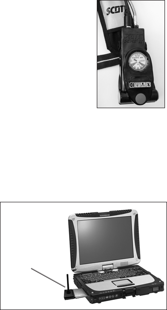
SEMS II PDA CONTROL CONSOLE
The SEMS II PDA Control Console is inte-
grated into the SCOTT SCBA as a part of
the remote air pressure gauge assembly
which hangs over the right shoulder of the
respirator user. The Control Console also
operates the PERSONAL ALERT SAFETY
SYSTEM (PASS) distress alarm intended
to assist in locating a respirator user who
is incapacitated or in need of assistance.
The PASS distress alarm in this model
reaches FULL ALARM in a total of 30 (thirty)
seconds. The Control Console has a set
of status lights, a dial air pressure gauge,
and three control buttons which can easily
be pressed with gloved hands. Power is
supplied by batteries in the SEMS II PDA
distress alarm battery compartment on the
SCBA backframe. FIGURE 1
SEMS II CONTROL CONSOLE
1 PANASONIC® is a registered trademark of PANASONIC CORPORATION CORPORATION
JAPAN, OSAKA, JAPAN.
2 Toughbook® is a registered trademark of PANASONIC CORPORATION OF NORTH AMERICA,
SECAUCUS NEW JERSEY.
Page 4 of 40
P/N 595166-01 Rev A 1/09
DRAFT COPY
Programming of the ID Tags and Portable Units allows the organization to
customize the identication of the SEMS II Portable Units. See SEMS II Pro-
gramming Guide, SCOTT P/N 595177-01 for complete details of programming
the SEMS II equipment.
SYSTEM DESCRIPTION CONTINUED...
When a respirator user opens the cylinder valve and begins use of a SCOTT
SCBA equipped with the SEMS II PDA, the Portable Unit will automatically
begin to operate. If the SEMS II PDR Base Station is present at time of en-
try, the SEMS II PDA must log-in with the Base Station before entry into the
hazardous area. The Base Station will then continue to monitor the SEMS
II PDA Portable Unit while it is in range until the respirator user terminates
use of the SCBA.
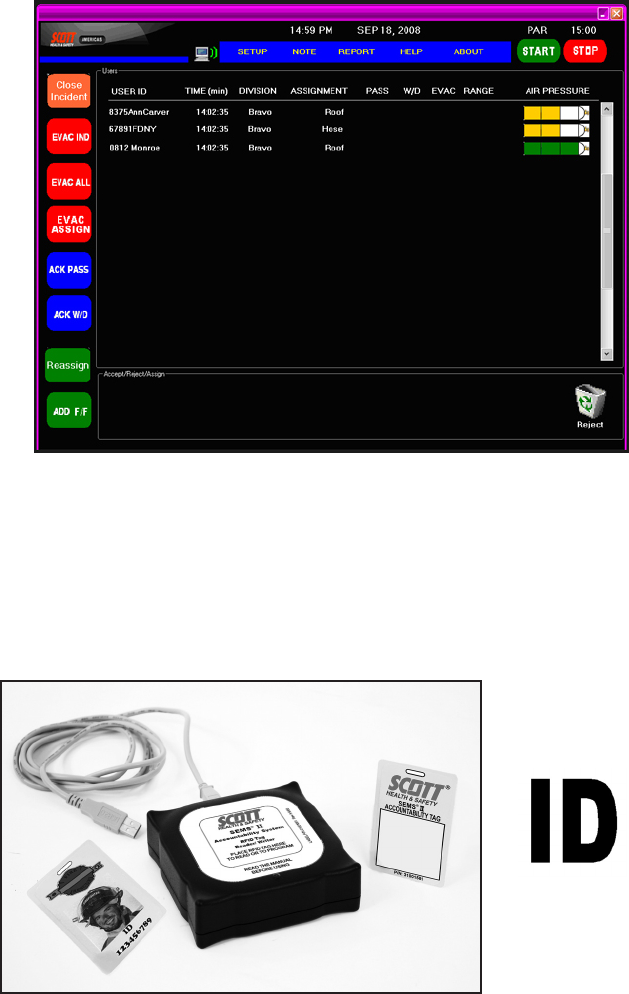
FIGURE 3
EXAMPLE OF BASE STATION SCREEN DISPLAY
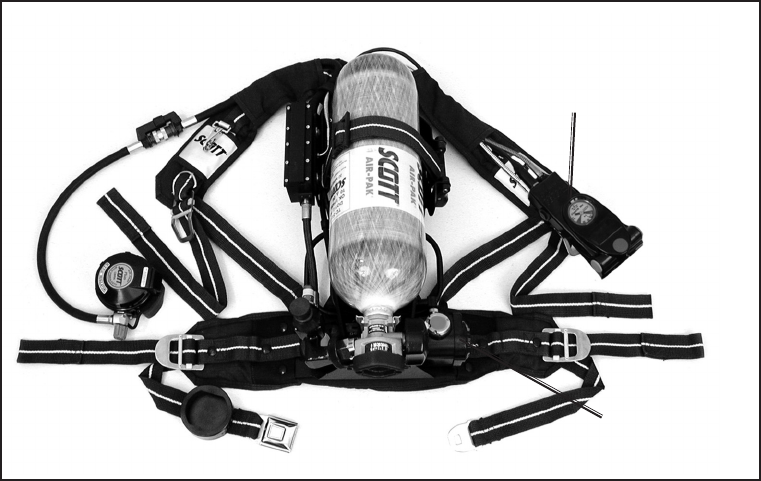
FIGURE 4
SEMS II RFID TAG WRITER, SCOTT P/N 200773-01.
ID ICON
Page 5 of 40 P/N 595166-01 Rev A 1/09
DRAFT COPY
Multiple organizations with SEMS II Accountability System equipment can
operate at a single event scene since each Base Station operator can select
and monitor which users log in on their Base Station. If another installation of
SEMS II equipment is used in the same area, the operation of each group can
remain discreet and separate between Portable Units and Base Stations.
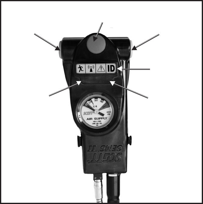
The SCOTT SEMS II PDA distress alarm Portable Unit, when added to a
SCOTT SCBA respirator, as shown in FIGURE 1, consists of a Sensor Module
with battery compartment mounted to the bottom of the respirator backframe,
a pressure gauge with transducer, and a Control Console mounted on the
wearer’s right shoulder strap at the pressure gauge location. The SEMS
II PDA Portable Unit requires six (6) AA batteries to operate in the Sensor
Module on the backframe.
FIGURE 5
AIR-PAK SCBA WITH SEMS II DISTRESS ALARM ASSEMBLY
SEMS II CONTROL
CONSOLE
ASSEMBLY
SENSOR MODULE AS-
SEMBLY
Installation of the SCOTT SEMS II PDA distress alarm requires some dis-
assembly of the respirator and should only be performed by an authorized
service center. Contact SCOTT HEALTH AND SAFETY, Monroe, NC at
1-800-247-7257 for details.

Page 6 of 40
P/N 595166-01 Rev A 1/09
DRAFT COPY
PAK-TRACKER LOCATOR SYSTEM
The SCOTT PAK-TRACKER Locator System is a two part electronic sys-
tem consisting of a PAK-TRACKER Transmitter integrated into the SCOTT
SEMS II distress alarm, and a PAK-TRACKER Hand Held Receiver, which
is a directional receiver used to locate the signal coming from the PAK-
TRACKER Transmitter. The PAK-TRACKER locator system transmitter is
activated with the PASS alarm. The transmitter emits a radio signal with a
unique ID number that can be tracked using the SCOTT PAK-TRACKER
Hand Held Receiver unit.
The PAK-TRACKER Hand Held Receiver is then used as a directional receiver
to assist in leading the rescue team to the activated transmitter. By pointing the
PAK-TRACKER Hand Held Receiver in the direction of the strongest relative
signal, the rescue crew can follow the signal toward the respirator user who
is incapacitated or in need of assistance.
Use of this equipment must be part of a complete personnel accountability
system that includes procedures for monitoring the deployment and condition
of all users. Do not rely on the PAK-TRACKER Locator System as the only
technique for locating missing personnel. Failure to use this equipment prop-
erly may actually increase the time needed to locate and rescue personnel.
TRAINING AND PRACTICE IN REALISTIC EMERGENCY SIMULATIONS IS
REQUIRED BEFORE USE OF THIS EQUIPMENT. The users must become
thoroughly familiar with the operation and the limitations of the locator system
before entering a potentially hazardous or life threatening situation.
The PAK-TRACKER Locator System User Instructions, SCOTT part number
595102-01, contain essential information on the use of the locator system and
must be used as the basis of training for use of the whole system including use
with a SEMS II distress alarm equipped with the PAK-TRACKER Transmitter.
The PAK-TRACKER Locator System User Instructions include an overview
of the system operation, limitations of the system, as well as any user level
maintenance for the PAK-TRACKER Locator System equipment. Copies of
the PAK-TRACKER Locator System User Instructions are available from your
SCOTT distributor or from SCOTT Health and Safety.
FIGURE 6
PAK-TRACKER
HAND HELD RECEIVER
WARNING
READ AND UNDERSTAND THIS ENTIRE MAN-
UAL AND THE PAK-TRACKER LOCATOR
SYSTEM MANUAL, P/N 595102-01. TRAINING IS
REQUIRED BEFORE USE OF THIS EQUIPMENT
IN A HAZARDOUS SITUATION. THE TRAINING
MUST INCLUDE AN UNDERSTANDING OF THE
LIMITATIONS OF THE EQUIPMENT AND HOW TO
INTERPRET LOCATING INFORMATION, ALONG
WITH EXTENSIVE PRACTICE WITH THE SYSTEM
IN A VARIETY OF ENVIRONMENTS. USE OF THIS
EQUIPMENT MUST A PART OF A COMPLETE
PERSONNEL ACCOUNTABILITY SYSTEM. AL-
WAYS UPDATE TRAINING WITH EACH NEW
PIECE OF EQUIPMENT. USE OF A PAK-TRACKER
LOCATOR SYSTEM WITHOUT PROPER TRAIN-
ING MAY PLACE THE USERS AT HIGHER RISK
IN DANGEROUS SITUATIONS WHICH COULD
RESULT IN SERIOUS INJURY OR DEATH.
Page 7 of 40 P/N 595166-01 Rev A 1/09
DRAFT COPY
DATA LOGGING FEATURE
Respirators equipped with a SCOTT SEMS II distress alarm integrated
PASS device are compliant to NFPA 1982, 2007 Edition. The PASS
device includes on-board electronics which maintain a running log of
event data including start-up, shut-down, and PASS activation. The
SCOTT DATA LOGGER Computer Interface is required to access the
information. Instructions for downloading the data log are SCOTT P/N
595123-01 and are included with the computer interface.
Page 8 of 40
P/N 595166-01 Rev A 1/09
DRAFT COPY
WARNING
THE INFORMATION BELOW IS MEANT TO
SUPPLEMENT, NOT REPLACE, THE TRAINING,
SUPERVISION, MAINTENANCE, AND OTHER
ELEMENTS OF YOUR ORGANIZED RESPIRA-
TORY PROTECTION PROGRAM. SEE WARNING
ON FIRST PAGE OF THIS DOCUMENT. FAILURE
TO COMPLY WITH THESE INSTRUCTIONS MAY
RESULT IN SERIOUS INJURY OR DEATH.
WARNING
USERS OF RESPIRATORS EQUIPPED WITH THE
SEMS II DISTRESS ALARM MUST BE AWARE OF
THE PROPER OPERATION OF THE DISTRESS
ALARM. FAILURE TO RECOGNIZE A MALFUNC-
TION OF THE SEMS II DISTRESS ALARM AND
TAKE PROPER CORRECTIVE ACTION MAY RE-
SULT IN SERIOUS INJURY OR DEATH.
OPERATION AND USE OF THE
SEMS II DISTRESS ALARM (PASS)
ACTIVATION
Prepare the respirator for use according to the user instructions provided
with the respirator.
Install the batteries in the SEMS II Sensor Module according to the BATTERY
INSTALLATION section of this instruction.
With proper batteries and a charged air cylinder installed, the SEMS II distress
alarm device is automatically activated when the respirator is pressurized by
opening the cylinder valve of the respirator.
To indicate activation, the sensor module will sound 3 quick audible chirps
and the green light located on the control console will ash approximately
once a second. See FIGURE 4. The SEMS II distress alarm is now in the
automatic mode.
In the automatic mode, the SCOTT SEMS II distress alarm constantly moni-
tors motion of the respirator backframe. The sensor module is located on
the respirator backframe beneath the air cylinder and contains the motion
sensor and the audible alarm. If the sensor module does not sense motion of
the respirator for twenty (20) seconds, the SEMS II distress alarm will signal
a pre-alarm condition. If there is still no motion of the respirator for the next
twelve (12) seconds the full alarm will sound.
The SCOTT SEMS II distress alarm will remain activated in the automatic
mode until turned OFF according to these instructions.
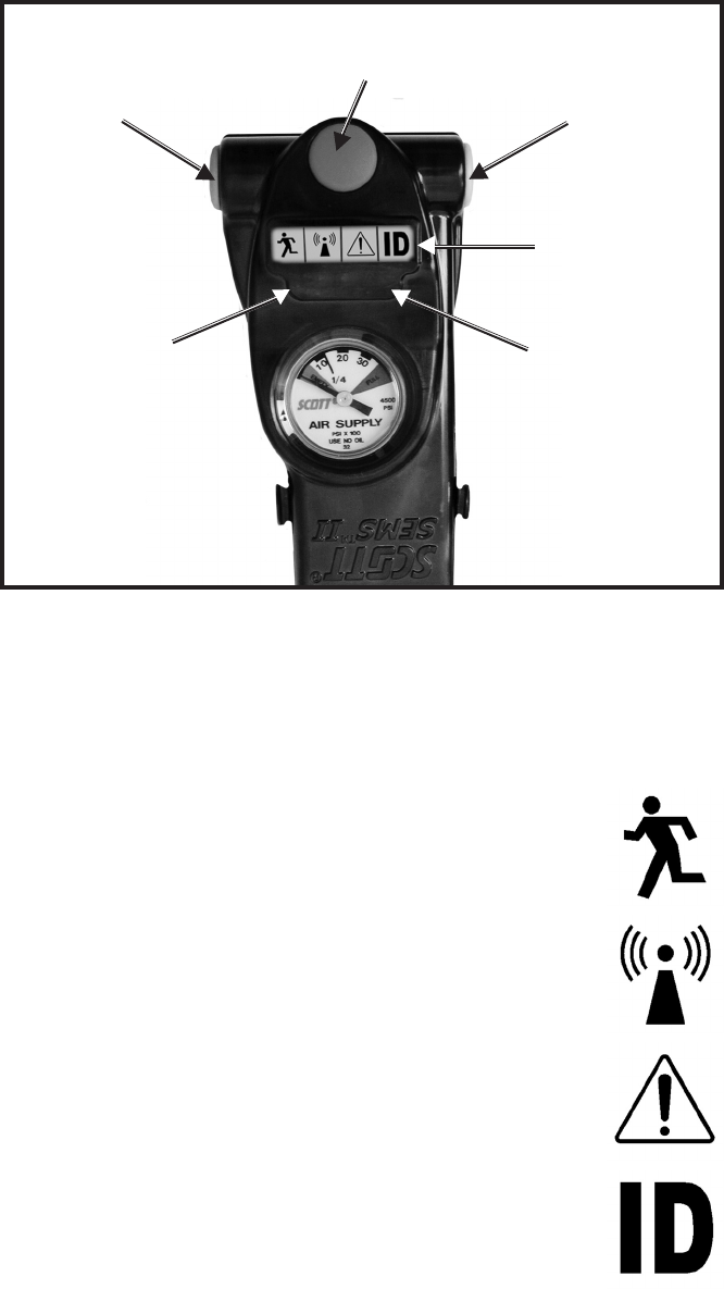
FIGURE 8
THE CONTROL CONSOLE
(PRESSURE GAUGE DEPENDS ON SYSTEM PRESSURE–
GAUGE IN ILLUSTRATION IS 4500 PSIG)
RESET BUTTON
(YELLOW INDICATOR)
MANUAL ALARM BUTTON
(RED INDICATOR)
RED
SIGNAL
LIGHT
CONSOLE
DISPLAY
GREEN
SIGNAL
LIGHT
WITHDRAW BUTTON
(BLUE INDICATOR)

Page 9 of 40 P/N 595166-01 Rev A 1/09
DRAFT COPY
WARNING
USERS OF RESPIRATORS EQUIPPED WITH THE
SEMS II DISTRESS ALARM MUST BE AWARE OF
THE PROPER OPERATION OF THE DISTRESS
ALARM. FAILURE TO RECOGNIZE A MALFUNC-
TION OF THE SEMS II DISTRESS ALARM AND
TAKE PROPER CORRECTIVE ACTION MAY RE-
SULT IN SERIOUS INJURY OR DEATH.
OPERATION OF THE SEMS II DISTRESS ALARM
CONTINUED ON NEXT PAGE...
PRE ALARM:
If the respirator remains motionless for more than twenty (20) seconds, the
SEMS II distress alarm will automatically sound a pre-alarm
When the pre-alarm occurs, the green ashing light on the control console is
replaced by a bright red light which ashes approximately once a second and
is accompanied by an ascending/descending audible tone which increases
in volume during the pre-alarm cycle.
If the respirator user is not incapacitated or not in need of assistance, move
the respirator to reset the pre-alarm. When reset, the ashing red light will
be replaced by the ashing green and the ascending/descending tone will
stop.
Remember that the motion sensor is in the sensor module on the respirator
backframe beneath the air cylinder. Actual movement of the respirator back-
frame is required to reset the pre-alarm. Shaking the control console will not
reset the SEMS II distress alarm .
To manually reset the pre-alarm, press and hold the reset button on the side
of the control console until three (3) quick audible chirps are heard and the red
ashing light on the control console is replaced by the green ashing light.
FULL ALARM:
If the respirator remains motionless through the twelve (12) second pre-alarm
cycle, the SEMS II distress alarm will go into full alarm. This may indicate that
the user is incapacitated or in need of assistance and can not move.
Full alarm is indicated by a loud, almost continuous 3 tone chirp from the
sensor module accompanied by the ashing red signal light on the control
console. The unit will also send a notication of PASS activation to the SEMS
II Base Station that will appear on the computer display. In addition, the Pak-
Tracker Locator transmitter in the unit will begin transmitting the unique ID
number that can be received by the Pak-Tracker Hand Held Unit.
To reset the full alarm condition, press the reset button twice. See FIGURE
4.
After the full alarm has been silenced by pressing the reset button twice, the
SEMS II distress alarm will remain activated in the automatic mode with the
green light ashing once per second. As long as the respirator is pressurized,
there must be movement of the respirator at least every twenty (20) seconds
or the distress alarm will again go into pre-alarm followed by full alarm as
described above.
MANUAL ALARM:
If the respirator user requires immediate assistance, pressing the manual
alarm button located on the front of the control console will immediately sound
the full alarm. See FIGURE 4. The manual alarm may be activated at any
time, even when the respirator is not pressurized.
If the manual alarm is activated when the respirator is not pressurized, press
the reset button twice to silence the alarm. The SEMS II distress alarm will
remain on in automatic mode. To turn the unit off, press the reset twice again
while the unit is not in alarm mode.
Remember, the loud audible alarm and ashing red light can be turned on at
any time by pressing the manual alarm button on the control console.

Page 10 of 40
P/N 595166-01 Rev A 1/09
DRAFT COPY
OPERATION AND USE OF THE SEMS II DISTRESS ALARM
CONTINUED...
TO TURN OFF THE SEMS II DISTRESS ALARM
When use of the respirator with the SEMS II distress alarm is no longer
required, close the cylinder valve on the respirator and vent the residual air
from the respirator system by opening the regulator purge valve. After all
the air ow stops, close the regulator purge valve and press the reset button
twice to turn off the SEMS II distress alarm. If there is air pressure left in the
system, the green ashing light will continue to ash while a fteen second
beep sequence is heard from the sensor module as the residual air bleeds
from the system. As soon as the air has completely bled from system, the
unit will sound a quick two tone chirp and the PASS DEVICE distress alarm
will be inactive. If there is no pressure in the system when the RESET button
is pressed twice, there will be no fteen second beep sequence. When the
unit sounds a quick two tone chirp, the SEMS II distress alarm is inactive. If
there is any air pressure left in the system, the PASS DEVICE distress alarm
will return to the active mode.
If the respirator cylinder valve is open and/or pressure remains in the respi-
rator, the SEMS II distress alarm can not be turned off. Pressing the reset
button when the respirator is pressurized will only reset an alarm condition
and return the SEMS II distress alarm to automatic mode.
If the respirator cylinder is turned off and depressurized without pressing the
reset button twice, the SEMS II distress alarm will continue to monitor mo-
tion in automatic mode. This means that the SEMS II distress alarm may be
used to monitor motion after the respirator is turned off and depressurized.
Resetting the full alarm after the respirator has been depressurized will not
turn off the SEMS II distress alarm. Press the reset switch twice with no alarm
condition to turn off the SEMS II distress alarm (there will be no fteen (15)
second beep sequence and two tone chirp will be heard).
Page 11 of 40 P/N 595166-01 Rev A 1/09
DRAFT COPY
LOW BATTERY
In a low battery condition, the SEMS II distress alarm will produce a single
audible chirp from the sensor module once every two (2) seconds and the
green light on the control module will not ash.
While in low battery condition, the SEMS II distress alarm will continue to
operate for a period of time greater then the longest duration cylinder avail-
able for the respirator. However, the batteries must be replaced before the
respirator is used again. See the BATTERY REPLACEMENT section of these
instructions.
If batteries are completely discharged or have not been installed, there will
be no light or sound and the unit will not operate.
BATTERY TEST
When the SEMS II PDA distress alarm is in the off condition (cylinder valve
closed with no ashing lights, the batteries in the entire system can be checked
by depressing and holding the RESET button on the console.
• A GREEN LED will illuminate on the Control Console, if there is suf-
cient battery power remaining,
• A RED LED indicates that the batteries are low and must be replaced
before the respirator is to be used again.
If a low battery message occurs, ALL batteries must be changed before the
respirator is used again. See the BATTERY REPLACEMENT section of this
instruction for details.
WARNING
DO NOT USE A RESPIRATOR IN A LOW BATTERY
CONDITION. FAILURE TO REPLACE THE BAT-
TERIES AND/OR CONTINUING WITH MULTIPLE
USES OF THE RESPIRATOR AFTER THE LOW
BATTERY CONDITION HAS BEEN INDICATED
BY THE SEMS II DISTRESS ALARM MAY RESULT
IN FAILURE OF THE SEMS II DISTRESS ALARM
DURING USE AND POSSIBLE INJURY OR DEATH
OF THE USER.
Page 12 of 40
P/N 595166-01 Rev A 1/09
DRAFT COPY
CONSOLE BUTTONS
There are three (3) buttons on the Control Console. They are as follows:
MANUAL ALARM Red To activate the PASS alarm manually
WITHDRAW Blue To signal or acknowledge a withdraw action
RESET Yellow Used for various functions.
CONSOLE DISPLAY
The Console Display has four (4) ICON Symbol segments that light in response
to specic conditions. The four are:
EVAC
The EVAC symbol (Running Man) lights when either the Base
Station sends a call to the user(s) to EVACUATE (ashed
RED), or the user presses the WITHDRAW Button on the
Control Console (ashes YELLOW).
RANGE
The RANGE symbol lights when the user is out of range of the
Base Station. The Base Station displays a similar message.
PASS ALARM
The PASS ALARM symbol lights when the user’s PASS is
activated. The Base Station displays a similar message.
ID
The ID symbol lights to indicate that the input from the user’s
Accountability Tag has been accepted and the unit is now
programmed with that user’s identication.
OPERATION AND USE OF THE
SEMS II ACCOUNTABILITY SYSTEM
FIGURE 9
THE CONTROL CONSOLE
RESET BUTTON
(YELLOW INDICATOR)
MANUAL ALARM BUTTON
(RED INDICATOR)
RED
SIGNAL
LIGHT
CONSOLE
DISPLAY
GREEN
SIGNAL
LIGHT
WITHDRAW BUTTON
(BLUE INDICATOR)

Page 13 of 40 P/N 595166-01 Rev A 1/09
DRAFT COPY
USER ACCOUNTABILITY FUNCTIONS
From the User's standpoint, the primary accountability functions of
the SEMS II equipment are Personal Alert Safety System (PASS)
Distress Alarm, the EVACUATION Signal, and the WITHDRAW
Signal.
1. When the PASS Distress Alarm is activated to full alarm, the SEMS II
PDA Portable Unit will send a signal to the Base Station. Activation of
the full alarm can be either by manual activation of the user pressing the
RED Manual Alarm Button, or by automatic activation from lack of user
movement. The PASS symbol will ash RED quickly. When the Base
Station operator acknowledges the message, the PASS symbol will ash
RED slowly.
2. The EVACUATION Signal is sent from the Base Station to the SEMS II
PDA Portable Unit. It can be handled one of two ways:
a) All-Call Signal: The Base Station will send a signal to all SEMS II PDA
Portable Units logged on to it. When received, the Control Console
will sound an audible signal and the “EVAC” symbol will ash RED
quickly. Every respirator user must acknowledge this signal by pressing
twice the yellow RESET button on the Control Console. After the Base
Station acknowledges, the “EVAC” symbol will remain ashing slowly
until user leaves hazardous area and shuts down the respirator.
b) Selective Evacuation Alarm: The Base Station will send a signal to only
selected units logged on to it. When received, the Control Console will
sound an audible signal and the “EVAC” symbol will ash RED quickly.
The selected respirator user must acknowledge this signal by pressing
twice the yellow RESET button on the Control Console. After the Base
Station acknowledges, the “EVAC” symbol will remain ashing slowly
until user leaves hazardous area and shuts down the respirator.
3. The user selects the WITHDRAW Signal to inform the Base Station that
the user is withdrawing from the hazardous atmosphere. The user presses
and holds the blue “WITHDRAW” button on the Control Console for at
least two seconds. The "EVAC" icon on the console will ash YELLOW
quickly and the WITHDRAW message appears on the Base Station. After
the Base Station acknowledges, the “EVAC” symbol will remain ashing
slowly until user leaves hazardous area and shuts down the respirator.
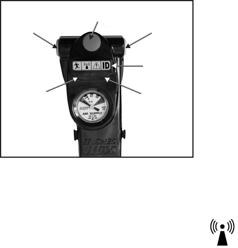
4. The RANGE symbol lights as follows:
YELLOW flashing slowly-
The PDA Unit is ON but the base station has not accepted it.
GREEN flashing once every 10 seconds-
The PDA Unit is logged onto base station and has been accepted.
The PDA Unit must be able to communicate with the Base Station
at least once a minute to remain IN RANGE.
YELLOW flashing fast-
The PDA Unit is OUT OF RANGE of the base station.
5. End-of-Service Indicators
In addition to the other end-of-service indicators on the respirator, the
air supply cylinder levels are monitored by the SEMS II PDA Unit and
transmitted to the Base Station. When the cylinder reaches one quarter
of full pressure, the Console sounds a “LOW AIR” warning with an audible
alarm as well as transmitting a “LOW AIR” warning to the Base Station.
The “LOW AIR” alarm will continue to operate until the respirator is shut
down.
OPERATION AND USE OF THE SEMS II ACCOUNTABILITY SYSTEM
CONTINUED ON NEXT PAGE...

Page 14 of 40
P/N 595166-01 Rev A 1/09
DRAFT COPY
OPERATION AND USE OF THE
SEMS II ACCOUNTABILITY SYSTEM CONTINUED...
BASE STATION PREPARATION
COMPUTER REQUIREMENTS
The SCOTT SEMS II MESH GATEWAY software is PC based and requires a
minimum of WINDOWS® 2000 or higher and a 486 or faster processor with
approximately ten (10) megabytes of free disc space. The PCMCIA Com-
munications Card requires a PC Card port on the computer.
NOTE
YOU MUST INSTALL THE SEMS II MESH GATEWAY SOFTWARE FIRST
BEFORE INSTALLING THE PCMCIA CARD IN THE COMPUTER.
TO INSTALL SEMS II MESH GATEWAY SOFTWARE
1. Place the SCOTT SEMS II MESH GATEWAY software CD-ROM in the
CD drive on your computer.
2. Select “SEMS II MESH GATEWAY” to install the Software. Follow the
instructions on the screen. You may need to close all other applications
to install this program.
3. When the installer creates a folder called “SEMS II MESH GATEWAY”
for the les, select “Continue.”
4. When the set up is completed successfully, select “OK.” You will return
to the Installer screen.
5. When nished installing, close the Installer.
NOTE
IF YOU HAVE ANY PROBLEMS INSTALLING THE SOFTWARE, DO NOT
USE THE SYSTEM. CONTACT SCOTT FOR ASSISTANCE.
TO INSTALL SEMS II MESH GATEWAY PCMCIA CARD
After installing the SCOTT SEMS II MESH GATEWAY software on your com-
puter, install the PCMCIA Communications Card as follows:
1. Hold the PCMCIA Communications Card as shown in FIGURE X with the
antenna pointing UP.
2. Insert the PCMCIA Communications Card into the PC Card slot until it
snaps in.
3. When your computer says new equipment installed, select OK.
Operation of the SEMS II Accountability System Base Station requires instal-
lation of the SEMS II MESH GATEWAY KIT, SCOTT P/N 200772-01, which
includes the Graphic User Insterface (GUI) Software and the PCMCIA Com-
munications Card.
FIGURE 10
INSTALLATION OF THE SEMS II PCMCIA CARD

Page 15 of 40 P/N 595166-01 Rev A 1/09
DRAFT COPY
FIGURE 11
BASE STATION
(ACTUAL APPEARANCE OF PERSONAL COMPUTER MAY VARY)
BASE STATION OPERATION
The SEMS II PDR Base Station must be operated by a fully trained individual
as part of a complete respiratory protection program. The Base Station Opera-
tor must have the ability to direct rescue operations as needed.
If using a battery powered portable computer, be sure the battery is fully
charged before beginning use at an incident.
The Base Station must be located in a safe, non-hazardous and non-am-
mable area away from the hazardous atmosphere where the respirators are
being used.
1. Start-up the personal computer in accordance with the computer’s user
instructions.
2. To open the SEMS II MESH GATEWAY Software, select the shortcut
created on you Desktop or in the “SEMS II MESH GATEWAY” folder in
“All Programs” in the Windows START menu.
BASIC FUNCTIONS OF THE SOFTWARE
The Primary functions of the Base Station Software are as follows:
1. ACCEPT/REJECT/ASSIGN Users
2. Monitor the Air Supply of each User
3. EVAC Signal
a. EVAC ALL – Evacuate all logged in Users
b. EVAC IND – Selected User Evacuation
4. WITHDRAW Notication from User
5. PASS Activation
6. Incident Record
OPERATION AND USE OF THE SEMS II ACCOUNTABILITY SYSTEM
CONTINUED ON NEXT PAGE...
Page 16 of 40
P/N 595166-01 Rev A 1/09
DRAFT COPY
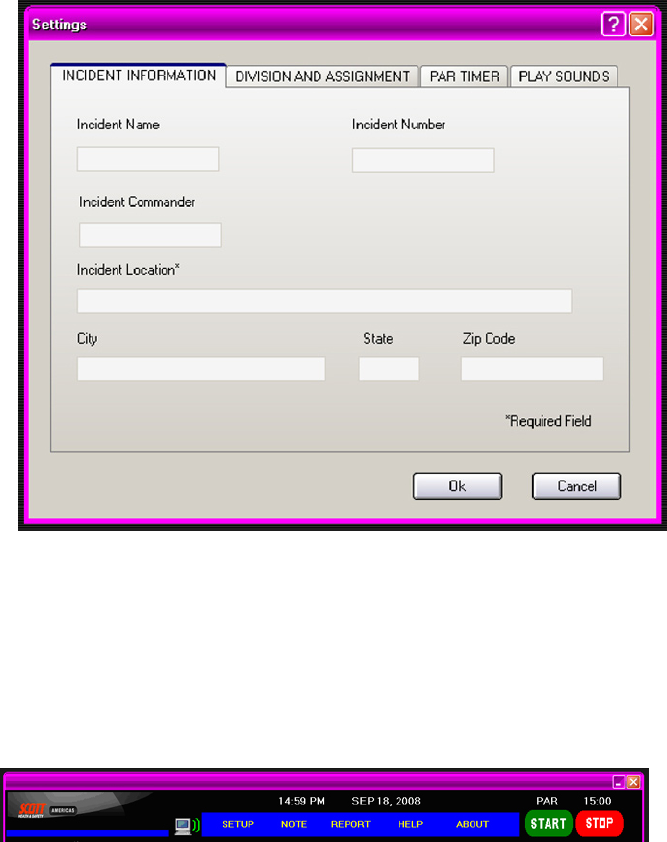
SEMS II ACCOUNTABILITY SOFTWARE DISPLAY SCREENS
1. SETTINGS
After the initial start-up screen, the rst screen that comes up is the SETTINGS
window where Incident Information is entered. Additional screens are provided
for DIVISION and ASSIGNMENTS and PAR TIMER options.
a. At a minimum, enter the “Incident Location” before proceeding
b. In the DIVISIONS AND ASSIGNMENTS tab, name the active divisions
and the projected assignments that will be used at the incident.
c. In the PAR Timer tab, set the Personal Accountability Report duration
according to your standard incident procedures.
d. Select whether the alert sounds will be active on the personal com-
puter.
2. TOOL BAR
a. SETUP – The SETTINGS screens can be accessed at any time from
the SETUP button on the toolbar.
b. NOTES – Notes regarding the Incident can be entered in the NOTES
Screen. There is space for a maximum of XXXX words in the NOTES
eld.
c. REPORT – Use the REPORT button to prepare an Incident Report.
d. ABOUT – Provides software version Information.
e. PAR TIMER – START/STOP of the PAR TIMER
OPERATION AND USE OF THE
SEMS II ACCOUNTABILITY SYSTEM CONTINUED...

Page 17 of 40 P/N 595166-01 Rev A 1/09
DRAFT COPY
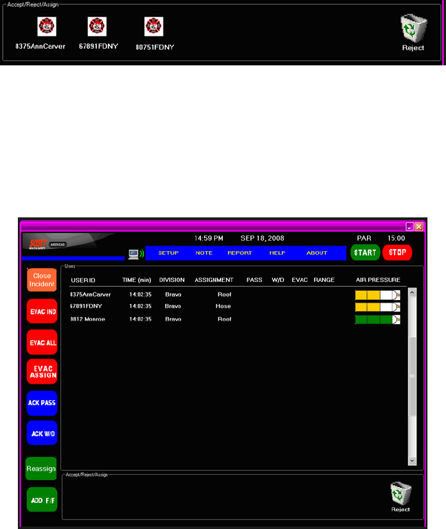
3. USERS DISPLAY
a. USER ID – Shows the ID of the Users who have logged on and been
accepted to the Incident
b. TIME (minutes) – Shows the amount of time the individuals have been
looged on
c. DIVISION – Shows the Divison of the User
d. ASSIGNMENT – Shows the Assignment of the User
e. PASS – Shows when the User's PASS has been activated.
f. W/D (WITHDRAW) – Shows whe the User has pressed the WITHDRAW
button on their Console
g. EVAC – Shows who has been given an EVAC signal
h. RANGE – Indicates whether the individual User is still in Range
i. AIR PRESSURE – Gives a graphic representation of the air pressure
remaining in the User's air supply cylinder from GREEN for full to YEL-
LOW for partial to RED for 1/4 cylinder or less.
4. SIDEBAR BUTTONS
a. CLOSE INCIDENT – Use the CLOSE INCIDENT button
to close the Incident File and save all settings.
b. EVAC IND – Use the EVAC IND button to select certain
individuals for evacuation.
c. EVAC ALL – Use the EVAC ALL button to evacuate all
active personnel.
d. ACK PASS – Use the ACK PASS button to acknowledge
a PASS signal.
e. ACK W/D – Use the ACK W/D to acknowledge a WITH-
DRAW signal.
f. Reassign – Use the Reassign button to change the se-
lected individual current assignment.
g. ADD F/F – Use the ADD F/F button to accept the selected
reghter.
OPERATION AND USE OF THE SEMS II ACCOUNTABILITY SYSTEM
CONTINUED ON NEXT PAGE...
Page 18 of 40
P/N 595166-01 Rev A 1/09
DRAFT COPY
5. ACCEPT/REJECT/ASSIGN – As Respirator users activate their systems,
their individual SEMS II ID’s will appear as icons in the ACCEPT/REJECT/
ASSIGN.
In accordance with your incident management procedures, the Base
Station Operator must choose to:
a. Accept the user as part of the accountability group for this Base Station.
Select the user’s icon and select the ADD F/F button on the side bar.
b. Reject the user as belonging to another accountability group for another
Base Station. Click and drag the user’s icon to the Trash container.
c. Assign the user to a particular assignment at the incident. Click the
user’s icon and select the Reassign button on the side bar.
FIGURE 12
COMPLETE DISPLAY SCREEN
OPERATION AND USE OF
THE SEMS II ACCOUNTABILITY SYSTEM CONTINUED...
Page 19 of 40 P/N 595166-01 Rev A 1/09
DRAFT COPY
BASE STATION OPERATOR RESPONSIBILITIES
1. RANGE
a. When a logged-in user goes out of range, the RANGE symbol will ap-
pear in the line entry for the user.
b. After X amount of time out of range, the RANGE symbol will begin to
ash indicating a possible problem. The Base Station operator must
respond to the user’s out of RANGE signal in accordance with the
organization’s incident management program.
2. AIR SUPPLY MONITORING
a. When the air supply cylinder reaches one-quarter of full pressure, the
end-of-service-time indicators (EOSTI) will activate on the SCBA. Within
ten seconds, a “LOW AIR” signal will be sent to the Base Station.
b. The Base Station operator must respond to the user’s low air signal
in accordance with the organization’s incident management program.
This may include issuing an EVAC signal to the individual with the low
air signal.
3. EVACUATION
a. To send an evacuation message to all logged-in respirator users, the
Base Station operator selects the “EVAC ALL” button on the Base Sta-
tion. The EVAC message will be sent to all accepted logged-in respirator
users.
b. To send an evacuation message to only selected respirator users, the
Base Station operator uses the cursor to select and highlight the users
to evacuate from the list of logged-in respirator users, and then presses
the “EVAC IND” button.
c. To send an evacuation message to respirator users on a particular
Assignment, the Base Station operator uses the cursor to select and
highlight the users to evacuate by Assignment from the list of logged-in
respirator users, and then presses the “EVAC ASSIGN” button.
d. As each respirator user receives an “EVAC” message, they must press
the RESET button on the Control Console to acknowledge the mes-
sage.
e. The Base Station listing of logged-in users will change color as each
respirator user responds to the EVAC message.
4. WITHDRAW
a. The respirator user may elect to leave the incident by pressing and
holding the BLUE Withdraw button on the Control Console. A YELLOW
EVAC symbol will appear in the line entry for the user.
b. After the Base Station acknowledges the WITHDRAW message, the
EVAC symbol will turn GREEN and remain until user leaves the haz-
ardous area and shuts down the respirator.
OTHER DISPLAY SCREEN FUNCTIONS
1. PAR Timer – Personnel Accountability Report Timer
a. The PAR Timer can be set to a specic interval to remind the Base
Station Operator ask for a “PAR” from all involved personnel.
b. To restart the PAR Timer, click on the PAR Timer icon and select “Re-
start.”
c. To adjust the time duration of the PAR Timer, select the PAR Timer icon
and select “Change Settings.”
2. NOTE – Note screen
a. To write a note that will be part of the incident log, select the Note
icon.
b. Maximum of XXX characters (letters or numbers) per note.
OPERATION AND USE OF THE SEMS II ACCOUNTABILITY SYSTEM
CONTINUED ON NEXT PAGE...
Page 20 of 40
P/N 595166-01 Rev A 1/09
DRAFT COPY
USE OF THE SEMS II PDA PORTABLE UNIT
Users of SCOTT respirators equipped with the SEMS II PDA Portable
Unit must be fully trained in the operation of the equipment as part of
a complete respiratory protection program before entering a hazardous
environment.
1. Start-up
a. Use of the SEMS II PDA Portable Unit begins when the user opens the
cylinder valve on the respirator to start respirator usage. The unit will
sound three chirps to indicate activation.
b. After a brief start-up sequence, the GREEN SIGNAL Light on the Con-
trol Console will light. An alert tone, a “BE-doop” to indicate the system
activity, is used for several functions. Whenever the alert tone occurs,
the user should look at the Portable Unit display for information.
2. Initialization and RANGE
a. After the start-up sequence, the SEMS II PDA Portable Unit will send an
Initialization signal to the Base Station to log in. The Base Station will
respond by ACCEPTING the identity assigned to that Portable Unit.
b. If the respirator user moves too far from the Base Station after logging-
in, the RANGE icon on the Control Console will ash indicating out of
range until the user moves back into the Base Station eld of operation
(up to one-half mile line-of-sight).
c. If the Portable Unit is too far away from the Base Station at start-up, or
if the Base Station is not powered up, the RANGE icon on the Control
Console display will light immediately from start-up and not be logged
into the Base Station. The SEMS II PDA Portable Unit will continue try-
ing to log-in to a Base Station until one comes into range or is powered
up.
d. Except for those functions which involve communication with the Base
Station, all other functions of the Control Console and SEMS II PDA
distress alarm are still operational when the Portable Unit is either out
of range or not logged into a Base Station.
FIGURE13
THE CONTROL CONSOLE
RESET BUTTON
(YELLOW INDICATOR)
MANUAL ALARM BUTTON
(RED INDICATOR)
RED
SIGNAL
LIGHT
CONSOLE
DISPLAY
GREEN
SIGNAL
LIGHT
WITHDRAW BUTTON
(BLUE INDICATOR)
RANGE ICON
OPERATION AND USE OF
THE SEMS II ACCOUNTABILITY SYSTEM CONTINUED...

Page 21 of 40 P/N 595166-01 Rev A 1/09
DRAFT COPY
3. PASS DISTRESS ALARM
a. If the user is in distress or becomes immobile, the SEMS II PDA PASS
distress alarm will operate in conjunction with the Portable Unit. If the
distress alarm is activated, either by the user pressing and holding the
Red MANUAL ALARM button for at least two seconds, or from the user
being immobile for the required time duration, the Portable Unit will send
a distress signal to the Base Station. The distress alarm will override
all other messages and actions of the Portable Unit. The PASS icon
will ash RED quickly.
b. When the Base Station acknowledges the user’s distress signal by
selecting the “ACK PASS” button on the Base Station, the PASS icon
on the Control Console will ash slowly while continuing to sound the
distress alarm on the respirator. The distress alarm will continue until
the user shuts down the respirator.
4. EVACUATION
a. If the respirator users are required to leave the hazardous area, the
Base Station operator can send an evacuation message to the Portable
Units of logged-in respirator users. This message can be sent either to
all logged-in users or to selected logged-in users as chosen from the
list on the Base Station.
b. The Portable Unit will emit the alert sound and the EVAC icon will begin
ashing on the Control Console.
c. When an EVAC icon begins ashing on the Control Console, the res-
pirator user must press twice the Yellow RESET button on the Control
Console to respond to the evacuation message. The EVAC icon will
continue to ash at a slower rate until the user leaves the hazardous
area and shuts down the respirator.
5. WITHDRAW
a. The respirator user may choose to leave the hazardous area. Pressing
and holding the Blue WITHDRAW button for at least two seconds will
send that message to the Base Station. The "EVAC" icon on the Con-
trol Console will ash YELLOW quickly as the WITHDRAW message
appears on the Base Station.
b. When the Base Station receives a user WITHDRAW message, the
Base Station Operator selects the ACK W/D button on the side bar.
c. After the Base Station acknowledges, the “EVAC” symbol on the COntrol
Console will remain ashing slowly until user leaves hazardous area
and shuts down the respirator.
6. Air Supply Cylinder Pressure
a. When the cylinder reaches one quarter of full pressure, the SEMS
II PDA sounds a LOW AIR warning with an audible alarm as well as
transmitting a LOW AIR alert to the Base Station.
b. The LOW AIR alarm will continue to operate until the respirator is shut
down. This LOW AIR alarm is in addition to the other end-of-service
indicators on the respirator.
7. Shutdown
a. After leaving the hazardous area and conrming that respirator use is
no longer required, doff the respirator according the user instructions
provided with the respirator.
b. Close the cylinder valve.
c. Press the Yellow RESET button twice.
d. The Control Console will sound the alert tone. The SEMS II PDA Por-
table Unit is now off.
PASS ICON
EVAC/WITHDRAW
ICON
EVAC/WITHDRAW
ICON
Page 22 of 40
P/N 595166-01 Rev A 1/09
DRAFT COPY
USE AS PART OF AN ACCOUNTABILITY SYSTEM
TRAINING REQUIRED BEFORE USE. Refer to the PAK-TRACKER Locator
System User Instructions, SCOTT P/N 595102-01 for complete details on the
use of the PAK-TRACKER Locator System. Use of this equipment must be
part of a complete personnel accountability system that includes procedures
for monitoring the deployment and condition of all users. Do not rely on the
PAK-TRACKER Locator System as the only technique for locating missing
personnel. A Rapid Intervention or Rescue team using the Hand Held Re-
ceiver must have a minimum of two (2) people. For their own safety, the team
members must pay attention to their surroundings at all times while using the
PAK-TRACKER Locator System.
The accountability system must include procedures for alerting the incident
commander and rescue teams when actuated transmitters or the missing
personnel have been found or when they have moved from their previous
location. It is the responsibility of the personnel accountability system to allow
for such contingencies without exposing individuals and teams to unneces-
sary dangers.
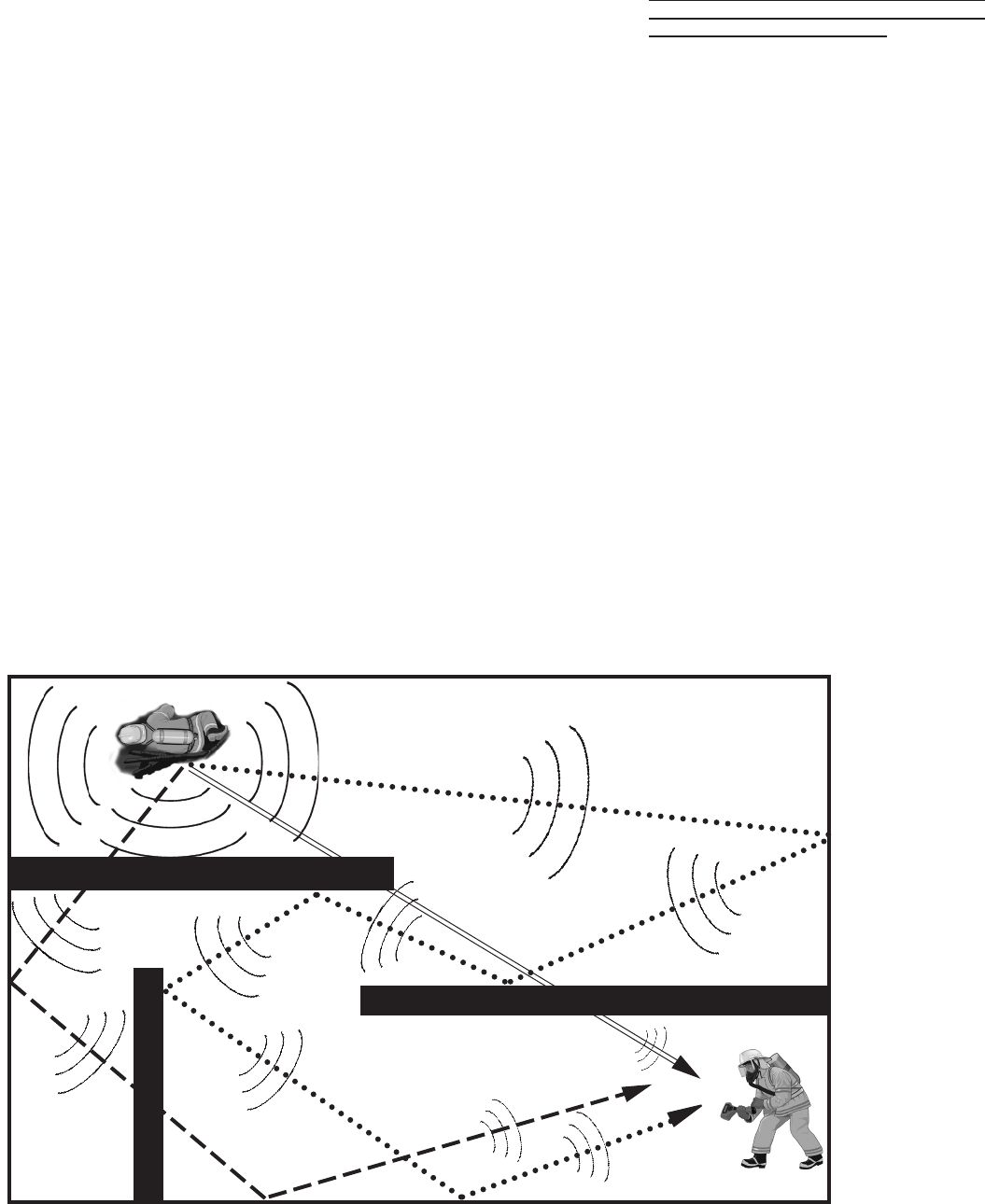
PRINCIPLES OF OPERATION
OF THE PAK-TRACKER LOCATOR SYSTEM
The SCOTT PAK-TRACKER locator system is an electronic system consist-
ing of a Hand Held Receiver and a Transmitter built into the SEMS II Sensor
Module on the SCBA backframe. The Transmitter is activated when the PASS
is in Full Alarm. When a Transmitter is activated, it sends out a radio signal in
all directions that is received by the Hand Held Receiver. Understanding how
the radio signal from a Transmitter behaves and how the Hand Held Receiver
receives and displays the strength of that signal are critical to understanding
the operation of the SCOTT PAK-TRACKER locator system.
WARNING
READ AND UNDERSTAND THIS ENTIRE MAN-
UAL AND THE PAK-TRACKER LOCATOR
SYSTEM MANUAL, P/N 595102-01. TRAINING IS
REQUIRED BEFORE USE OF THIS EQUIPMENT
IN A HAZARDOUS SITUATION. THE TRAINING
MUST INCLUDE AN UNDERSTANDING OF THE
LIMITATIONS OF THE EQUIPMENT AND HOW TO
INTERPRET LOCATING INFORMATION, ALONG
WITH EXTENSIVE PRACTICE WITH THE SYSTEM
IN A VARIETY OF ENVIRONMENTS. USE OF THIS
EQUIPMENT MUST A PART OF A COMPLETE
PERSONNEL ACCOUNTABILITY SYSTEM. AL-
WAYS UPDATE TRAINING WITH EACH NEW
PIECE OF EQUIPMENT. USE OF A PAK-TRACKER
LOCATOR SYSTEM WITHOUT PROPER TRAIN-
ING MAY PLACE THE USERS AT HIGHER RISK
IN DANGEROUS SITUATIONS WHICH COULD
RESULT IN SERIOUS INJURY OR DEATH.
FIGURE 14
MULTIPLE SIGNAL PATHS ARE POSSIBLE
OPEARATION AND USE OF
THE SCOTT PAK-TRACKER LOCATOR SYSTEM
Page 23 of 40 P/N 595166-01 Rev A 1/09
DRAFT COPY
WARNING
CONTINUED TRAINING AND PRACTICE IN A
VARIETY OF SITUATIONS IS ESSENTIAL TO
DEVELOPING THE SKILLS TO PROPERLY IN-
TERPRET THE INFORMATION PROVIDED BY
THE PAK-TRACKER LOCATOR SYSTEM. USE
OF THIS EQUIPMENT WITHOUT TRAINING AND
PRACTICE MAY JEOPARDIZE ALL PERSONNEL
INVOLVED WHICH COULD LEAD TO SERIOUS
INJURY OR DEATH.
Successful operation of the PAK-TRACKER Locator system depends heavily
on the interpretation of the relative signal strength information displayed on
the Hand Held Receiver along with all other available information about the
possible location of the activated transmitter.
The Hand Held Receiver is very sensitive in responding to small differences
in signal strength. The relative strength of the Transmitter signal detected by
the Hand Held Receiver will vary depending on:
1. The distance from the Transmitter to the Hand Held Receiver,
2. The path the Transmitter signal has taken to get to the Hand Held Re-
ceiver,
3. The materials between the Transmitter and the Hand Held Receiver which
may have affected the signal from the Transmitter.
The user of the Hand Held Receiver must interpret the readings on the Hand
Held Receiver display along with other information, such as:
– Training and knowledge in systematic search and rescue techniques,
– their sense of sight (watch where you are going),
– their sense of sound (listen for an activated PASS device),
– the deployment of the missing personnel,
– knowledge of the building layout and building materials,
Do not rely solely on the readings from the Hand Held Receiver to locate the
activated Transmitter.
Refer to the PAK-TRACKER Locator System User Instructions, SCOTT P/N
595102-01 for complete details on the use of the PAK-TRACKER Locator
System.
Page 24 of 40
P/N 595166-01 Rev A 1/09
DRAFT COPY
REGULAR OPERATIONAL INSPECTION OF
THE SEMS II DISTRESS ALARM,
THE SEMS II ACCOUNTABILITY SYSTEM,
AND THE PAK-TRACKER LOCATOR SYSTEM
Inspect and test the SCOTT SEMS II distress alarm, SEMS II Accountability
System, and the PAK-TRACKER Locator System along with the inspection
and test of the SCOTT SCBA respirator before each use. Refer to the PAK-
TRACKER User Instructions, SCOTT P/N 595102-01, provided with the
SCOTT PAK-TRACKER Hand Held Receiver for complete details. Include the
following inspection procedures with the REGULAR OPERATIONAL INSPEC-
TION procedures dened in your respirator instructions. If any malfunction of
the respirator, the PAK-TRACKER Locator System, or the SEMS II distress
alarm or Accountability System is noted during the inspection, remove the
respirator from service and tag for repair by authorized personnel.
WARNING
FOLLOW REGULAR OPERATIONAL INSPEC-
TION PROCEDURE EXACTLY. IF THE SEMS II
DISTRESS ALARM DOES NOT ACTUATE, OR IF
ANY OTHER FEATURE DOES NOT OPERATE AS
DESCRIBED OR IF ANY OTHER OPERATIONAL
MALFUNCTION IS NOTED, DO NOT USE THE
RESPIRATOR.
CAUTION
THE PERFORMANCE PROPERTIES OF THE
SEMS II DISTRESS ALARM CANNOT BE PROP-
ERLY TESTED IN THE FIELD.
WARNING
THE PROPER OPERATION OF THE LOCATOR
SYSTEM CANNOT BE CHECKED WITHOUT
CHECKING ALL COMPONENTS OF THE SYSTEM
TOGETHER. THE REGULAR OPERATIONAL
INSPECTION MUST INCLUDE THE HAND HELD
RECEIVER AND THE BASE STATION WORKING
WITH EACH OTHER TO CONFIRM PROPER OP-
ERATION. FAILURE TO PROPERLY INSPECT THE
COMPLETE SYSTEM MAY RESULT IN FAILURE
OF ONE COMPONENT WHICH COULD LEAD TO
SERIOUS INJURY OR DEATH.
WARNING
IN SEVERAL OF THE INSPECTION PROCE-
DURES DESCRIBED A FULL ALARM WILL BE
OBSERVED. THE FULL ALARM CONDITION IN-
CLUDES AN AUDIBLE TONE THAT CAN EXCEED
95 DBA AT 3 METERS (9.9 FT.). TO PREVENT
POSSIBLE HEARING DAMAGE DURING TEST,
IMMEDIATELY RESET THE ALARM ON VERIFI-
CATION THAT IT IS FUNCTIONING PROPERLY.
WEAR HEARING PROTECTION IF PROLONGED
EXPOSURE TO A FULL ALARM CONDITION IS
ANTICIPATED.
NOTE
IN SEVERAL OF THE INSPECTION PROCEDURES DESCRIBED A FULL
ALARM WILL BE OBSERVED. THE FULL ALARM CONDITION INCLUDES
AN AUDIBLE TONE THAT CAN EXCEED 95 DBA AT 3 METERS (9.9
FT.). TO PREVENT POSSIBLE HEARING DAMAGE DURING TEST,
IMMEDIATELY RESET THE ALARM ON VERIFICATION THAT IT IS FUNC-
TIONING PROPERLY. WEAR HEARING PROTECTION IF PROLONGED
EXPOSURE TO A FULL ALARM CONDITION IS ANTICIPATED.
To test the PAK-TRACKER locator transmitter, you must have an operating
SCOTT PAK-TRACKER Hand Held Receiver.
NOTE
IF THIS INSPECTION IS DONE IN DIRECT SUNLIGHT IT MAY BE HELPFUL
TO SHADE THE LENS ON THE CONTROL CONSOLE WITH YOUR HAND
TO BE SURE THE LIGHTS ARE FLASHING AS DESCRIBED.
1. While performing the visual inspection of the respirator, visually inspect
all distress alarm enclosures, lenses, and wire conduits for cracks, wear
or other damage. If any damage is found, remove the respirator from
service and tag for repair by qualied personnel.
2. Inspect the SCOTT PAK-TRACKER Hand Held Receiver for any cracks
or signs of damage. If any damage is found, remove the unit from service
and tag for repair by qualied personnel.
3. Turn on the SCOTT PAK-TRACKER Hand Held Receiver according to
the operating instructions provided with the unit. Position the Hand Held
Receiver near by.
4. Turn on the computer with the SCOTT SEMS II MESH GATEWAY Soft-
ware with the PCMCIA Communications Card installed, according to this
instructions. Position the computer near by.
5. With the cylinder valve closed, press the manual alarm button, located
on the front of the distress alarm control console.
a) The manual alarm shall sound a loud almost continuous 3 tone chirp ac-
companied by ashing of the red signal light on the control console.
b) The PAK-TRACKER Hand Held Receiver will sound an alarm and display
the Identication Number of the SEMS II distress alarm as programmed
by the user's ID Tag. Use the SCROLL button on the Hand Held Receiver
to highlight the active ID number and press the ENTER button on the
Hand Held Receiver to select the displayed ID number. Point the unit
directly at and in close proximity to the respirator. The signal strength
displayed will be at its highest value.
c) Verify that the SEMS II functions are all operating properly and that
PASS and EVAC alarms and acknowledgements operate according to
these instructions.
Page 25 of 40 P/N 595166-01 Rev A 1/09
DRAFT COPY
6. Reset the manual alarm by pressing twice on the reset button located
on the side of the control console (fully depress reset button, release
and press again).
a) The unit will sound three chirps and the green light will ash.
b) The PAK-TRACKER Hand Held Receiver will reset to its non-alarm
state.
7. Turn the SEMS II distress alarm OFF by pressing the reset button twice
again. The unit will sound a two tone chirp and the green light will go
out.
8. Open the cylinder valve to pressurize the respirator system. The distress
alarm shall sound 3 quick chirps and the light on the control console
shall begin ashing green about once a second. The 3 chirps will sound
approximately the same time the VIBRALERT® in the mask mounted
regulator actuates briey. Make sure the air ow is stopped by pressing
the air saver/donning switch.
9. To check the pre-alarm, leave respirator motionless for twenty (20) sec-
onds. The green ashing light shall be replaced by a red ashing light.
An ascending/descending tone will sound increasing in volume. Leave
the respirator motionless.
10. After the pre-alarm condition occurs, check the pre-alarm reset. Within
twelve (12) seconds of the pre-alarm, move the respirator to activate the
motion sensor. The SEMS II distress alarm shall reset to the automatic
mode. The red ashing light shall be replaced by a green ashing light
and the ascending/descending tone shall stop.
Continue with regular operational inspection of respirator as directed by
respirator instructions or your approved respiratory protection plan proce-
dure. During the inspection the respirator must be moved or turned every
thirty (30) seconds or less to prevent the sounding of the full alarm.
After completion of all respirator checks and before turning off the
cylinder valve:
1. Check the manual reset of the pre-alarm. Leave the respirator motionless
until pre-alarm condition occurs. Within twelve (12) seconds press and
hold the reset button. Three (3) chirps shall sound, then release button.
The distress alarm shall reset to the automatic mode and the ashing red
light will be replaced by a ashing green light.
2. To check the full alarm, leave the respirator motionless until the pre-alarm
condition occurs. Do not reset.
a) The full alarm shall sound a loud almost continuous 3 tone chirp accom-
panied by ashing of the red signal light on the control console.
b) The PAK-TRACKER Hand Held Receiver will sound an alarm and
display the Identication Number of the SEMS II distress alarm which
appears on the label on the Sensor Module or the Control Console. Use
the SCROLL button on the Hand Held Receiver to highlight the active
ID number and press the ENTER button on the Hand Held Receiver to
select the displayed ID number. Point the unit directly at and in close
proximity to the respirator. The signal strength displayed will be at its
highest value.
WARNING
IF THE LOW BATTERY INDICATION (ONE
STEADY CHIRP EVERY TWO (2) SECONDS WITH
NO FLASHING LIGHTS) OCCURS AT ANY TIME
DURING REGULAR OPERATIONAL INSPEC-
TION, DO NOT USE THE RESPIRATOR. CHANGE
THE BATTERIES IN THE SENSOR MODULE
IMMEDIATELY AND REPEAT THE REGULAR OP-
ERATIONAL TEST OR TAKE THE RESPIRATOR
OUT OF SERVICE UNTIL THE BATTERIES ARE
CHANGED AND THE REGULAR OPERATIONAL
TEST IS SUCCESSFULLY PERFORMED.
REGULAR OPERATIONAL INSPECTION
CONTINUED ON NEXT PAGE...
Page 26 of 40
P/N 595166-01 Rev A 1/09
DRAFT COPY
REGULAR OPERATIONAL INSPECTION CONTINUED...
4. Reset the full alarm by pressing twice on the reset button located on the
side of the control console (fully depress reset button, release and
press again).
a) The loud alarm shall stop. The unit will sound three chirps and the green
light will ash. The unit shall reset to the automatic mode.
b) The PAK-TRACKER Hand Held Receiver will reset to its non-alarm
state.
5. Finish all respirator checks involving air ow and turn off the cylinder valve.
Use the purge valve to release all residual air pressure in the system.
With the cylinder valve OFF:
1. Check the continuing operation of the distress alarm. The distress alarm
shall remain active with green light ashing. Do not move respirator,
pre-alarm shall occur with twenty (20) seconds. Move respirator slightly,
pre-alarm shall reset, green light shall start ashing again.
2. To turn the distress alarm off, press the reset button twice (press, release
and press again). If there is air pressure left in the system, the green
ashing light will continue to ash while a fteen second beep sequence is
heard from the sensor module as the residual air bleeds from the system.
As soon as the air has completely bled from system, the unit will sound a
quick two tone chirp and the PASS DEVICE distress alarm will be inactive.
If there is no pressure in the system when the RESET button is pressed
twice, there will be no beep sequence. The distress alarm is now in the
“OFF” condition. If there is air pressure in the system, the PASS DEVICE
distress alarm will return to the active mode.
NOTE
IF THE LOW BATTERY INDICATION (ONE STEADY CHIRP EVERY TWO (2)
SECONDS WITH NO FLASHING LIGHTS) OCCURS AT ANY TIME DURING
REGULAR OPERATIONAL INSPECTION, DO NOT USE THE RESPIRATOR.
CHANGE THE BATTERIES IN THE SENSOR MODULE IMMEDIATELY AND
REPEAT THE REGULAR OPERATIONAL TEST OR TAKE THE RESPIRA-
TOR OUT OF SERVICE UNTIL THE BATTERIES ARE CHANGED AND THE
REGULAR OPERATIONAL TEST IS SUCCESSFULLY PERFORMED.
FORMED.
If any operational problems are found during the REGULAR OPERATIONAL
INSPECTION, do no use the respirator. Remove the respirator from service
and tag for repair by authorized personnel.
WARNING
FOLLOW REGULAR OPERATIONAL INSPEC-
TION PROCEDURE EXACTLY. IF THE SEMS II
DISTRESS ALARM DOES NOT ACTUATE, OR IF
ANY OTHER FEATURE DOES NOT OPERATE AS
DESCRIBED OR IF ANY OTHER OPERATIONAL
MALFUNCTION IS NOTED, DO NOT USE THE
RESPIRATOR.

Page 27 of 40 P/N 595166-01 Rev A 1/09
DRAFT COPY
When performing the REGULAR OPERATIONAL INSPECTION verify that
the Sensor Module lights are operating as described below:
OPERATION OF SENSOR MODULE LIGHTS
NOTE
THE ORANGE LIGHT IS A COMBINATION OF THE RED, GREEN, AND
WHITE LIGHTS THAT APPEARS ORANGE FROM A DISTANCE. AT
CLOSE RANGE THE INDIVIDUAL LIGHTS MAY BE VISIBLE.
ACTION... SENSOR MODULE LIGHTS WILL…
Start up PASS (Open Cylinder) ........................................ Bright Light then Flash GREEN
Normal Operation ..............................................................Flash GREEN
Respirator Low air (1/4 cylinder) .......................................Flash ORANGE (alternately)
Low Battery while ON ........................................................Flash ORANGE once a second
Shut down ........................................................................Lights OFF
Press RESET w/unit OFF (BATTERY TEST) ................. Bright Light then:
Flash GREEN if Good/Flash RED if Low
Press MANUAL ALARM with unit OFF ............................Flash GREEN then Full Alarm Flash RED
Press RESET from manual alarm ................................... Returns to Flash GREEN
PASS Pre-Alarm .............................................................. Flash RED (alternately)
PASS Full alarm ............................................................... Flash RED (simultaneously)
Install Cylinder ...................................................................Flash BLUE
Remove Cylinder ...............................................................Flash RED
In addition, when performing the REGULAR OPERATIONAL INSPECTION
on NxG7 respirators equipped with a SEMS II distress alarm, verify that the
Sensor Module lights also operate as described below:
ACTION... SENSOR MODULE LIGHTS WILL…
SENSOR MODULE LIGHTS ON THE NXG7 SCBA
Page 28 of 40
P/N 595166-01 Rev A 1/09
DRAFT COPY
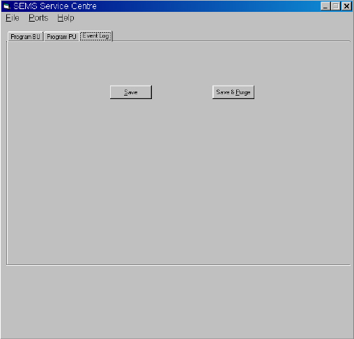
FIGURE 15
EVENT LOG SCREEN
EVENT LOG
Software within the Base Station maintains a data record or EVENT LOG
of each communication to or from the Base Station from the time it is
powered for use until it is powered down. To access and use the EVENT
LOG, proceed as follows:
BASE UNIT INTERFACE SETUP
Plug the Base Unit Interface Cable into a COM port as instructed in
the COMPUTER SETUP section the SEMS II Programming Instructions
SCOTT P/N 89506-01.
1. Plug the other end of the Base Unit Interface Cable into the connector
on the side of the Base Unit.
2. Run the SEMS II Fire Department Software and select the tab labeled
“EVENT LOG.” See FIGURE 5.
3. On the Base Unit, press and hold the EVAC button while turning on the
unit by pressing the POWER ON/OF button. Continue holding the EVAC
button until the screen displays, “COMMAND MODE: CS =0X2A58”.
(NOTE: CS number may vary depending on version of Base Unit.)
4. Choose either “SAVE” or “SAVE & PURGE” to save the information in the
EVENT LOG. The data will be saved as a text (.txt) le to a folder called
“Event Logs” in the same folder where the SEMS II Fire Department
Software resides on your computer [e.g.:(drive)\Program Files\SEMS II
Service Center\Event Logs\(folder)].
a) “SAVE” will save the EVENT LOG le to the Event Logs folder but
leaves the EVENT LOG information on the Base Unit.
b) “SAVE & PURGE” will save the EVENT LOG le to the Event Logs folder
and then erase the EVENT LOG information from the Base Unit.
5. The EVENT LOG le is a text (.txt) which may be viewed in either Microsoft
Excel or Microsoft Word. The data is in columns separated (delimited) by
commas. It may require some manipulation of the columns to facilitate
Page 29 of 40 P/N 595166-01 Rev A 1/09
DRAFT COPY
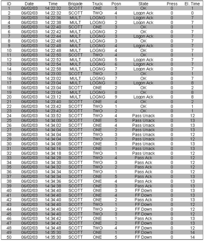
FIGURE 16
SAMPLE EVENT LOG
reading as shown in FIGURE 6. The columns contain information as fol-
lows:
Column 1 Event number Identication
Column 2 Date of Event
Column 3 Time of Event
Column 4 Fire Company (blank if the PDA and the Base Unit have the
same name.)
Column 5 Truck Number
Column 6 Seat Number or Position
Column 7 Event (LOGON, PASS, ACK, etc.)
Column 8 Cylinder Pressure at time of Event
Column 9 Total time the AIR-PAK respirator had been on at time of
Event
Columns 4, 5, and 6 identify a particular AIR-PAK respirator equipped
with the SEMS II PDA that has logged on to the Base Unit in the course
of the incident. The events include LOGON, PASS activation, Withdrawal,
Acknowledgment (ACK) of messages, etc.
Page 30 of 40
P/N 595166-01 Rev A 1/09
DRAFT COPY
CAUTION
RESPIRATOR SYSTEM MUST NOT BE PRES-
SURIZED WHEN BATTERIES ARE INSTALLED.
DAMAGE TO THE ELECTRONIC COMPONENTS
MAY RESULT IF BATTERIES ARE INSTALLED
WITH SYSTEM PRESSURIZED.
Respirators equipped with the PAK-ALERT with the integrated PAK-
TRACKER Locator System require six (6) “AA” cell batteries for operation.
The six (6) batteries power the Heads-Up Display, the PASS device, and
the PAK-TRACKER Transmitter. The batteries should be replaced only by
a trained maintenance technician in a clean area known to be nonflam-
mable. Replace batteries as follows:
1. Close respirator cylinder valve, open regulator purge valve letting out
all the trapped air, close regulator purge valve, press the reset button
twice. If there is air pressure left in the system, the green ashing light
will continue to ash while a fteen second beep sequence is heard from
the sensor module as the residual air bleeds from the system. As soon as
the air has completely bled from system, the unit will sound a quick two
tone chirp and the PASS DEVICE distress alarm will be inactive. If there
is no pressure in the system when the RESET button is pressed twice,
there will be no beep sequence. If there is air pressure in the system, the
PASS DEVICE distress alarm will return to the active mode.
NOTE
ALWAYS BE SURE THAT CYLINDER VALVE IS OFF AND THE PASS
DEVICE IS COMPLETELY INACTIVE BEFORE CHANGING BATTERIES.
NEVER REMOVE OR REPLACE BATTERIES WITH SYSTEM PRESSUR-
IZED OR DAMAGE MAY OCCUR TO ELECTRONIC COMPONENTS.
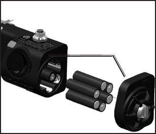
2. When replacing batteries on respirators, remove the cylinder and place
the respirator in a clean, non-hazardous area.
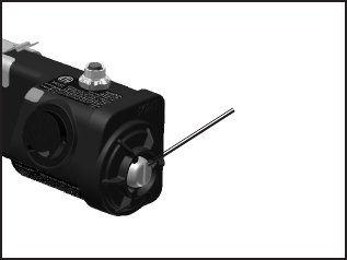
3. Use a Phillips driver to remove the Battery Housing Cover as shown in
FIGURE 17. Carefully remove the cover and set aside.
4. Remove used batteries from battery compartment by sliding them out of
the battery compartment.
5. Install six (6) fresh new “AA” batteries of the same type. Always replace
all batteries at the same time.
The battery holder is marked with the style and orientation of the batteries
required. See FIGURE 7.
Use six (6) each of one of the following 1.5 volt AA batteries:
– Duracell2 Alkaline MN1500
– Duracell Alkaline MX1500
– Duracell Alkaline PC1500
– Eveready Energizer3 Alkaline EN91
– Eveready Energizer Alkaline E91.
Do not mix batteries. Verify correct orientation of batteries as shown on
label inside the battery holder.
WARNING
THE SEMS II DISTRESS ALARM IS INTENDED TO
ASSIST IN LOCATING A PERSON WHO MAY BE
IN A LIFE THREATENING SITUATION. FAILURE
TO FOLLOW THE INSTRUCTIONS FOR OPENING,
CHANGING THE BATTERIES AND RE-CLOSING
THE BATTERY COMPARTMENT MAY RESULT
IN DAMAGE WHICH COULD CAUSE FAILURE
OF THE PASS DURING A LIFE THREATENING
EMERGENCY OR COULD CAUSE A FIRE OR
EXPLOSION IN A FLAMMABLE OR EXPLOSIVE
ATMOSPHERE POSSIBLY RESULTING IN INJURY
OR DEATH.
WARNING
BATTERIES MUST ONLY BE CHANGED IN
AN AREA KNOWN TO BE NONFLAMMABLE.
CHANGING THE BATTERIES IN A FLAMMABLE
ATMOSPHERE MAY CAUSE AN IGNITION
WHICH COULD RESULT IN SERIOUS INJURY
OR DEATH.
BATTERY REPLACEMENT
2 Duracell is a registered trademark of The Gillette Company, Boston, MA.
3 Energizer is a registered trademark of Eveready Battery Company, Inc., St Louis, MO.
WARNING
TO REDUCE THE RISK OF EXPLOSION USE
BATTERIES ONLY FROM THE LIST PROVIDED,
DO NOT MIX OLD BATTERIES WITH UNUSED
BATTERIES, AND DO NOT MIX BATTERIES FROM
DIFFERENT MANUFACTURERS. UNAUTHOR-
IZED SUBSTITUTION OF COMPONENTS MAY
IMPAIR INTRINSIC SAFETY AND CAUSE AN
EXPLOSION WHICH COULD LEAD TO SERIOUS
INJURY OR DEATH.
FIGURE 17
USE SCREWDRIVER
TO LOOSEN SCREW
AND REMOVE
COVER
Page 31 of 40 P/N 595166-01 Rev A 1/09
DRAFT COPY
CHECK YOUR WORK!
BEFORE ASSEMBLY OF BATTERY COVER,
CHECK TO SEE BOTH BATTERIES ARE FRESH,
NEW BATTERIES OF THE TYPE INDICATED
ABOVE AND THAT THEY HAVE BEEN IN-
STALLED PROPERLY.
FIGURE 18
BE SURE SEAL-
ING SURFACES ARE
CLEAN BEFORE RE-
ASSEMBLY
6. The battery cover must be installed so that it is water tight after replace-
ment. Clean the sealing rib around battery compartment and sealing face
of the cover, shown in FIGURE 18, by wiping with a clean damp cloth to
remove any dirt or foreign matter which might prevent a proper seal. Check
cover gasket for tears or cuts. If damage is found, remove respirator from
service and tag for repair by authorized personnel.
7. Install battery cover and tighten the cover screw until snug.
AFTER REPLACEMENT OF BATTERIES, PERFORM A REGULAR
OPERATIONAL INSPECTION BEFORE RETURNING RESPIRATOR
TO SERVICE.
Page 32 of 40
P/N 595166-01 Rev A 1/09
DRAFT COPY
CLEANING, MAINTENANCE AND STORAGE
Cleaning, maintenance and storage of a respirator with a SEMS II distress
alarm shall be done as part of the normal respirator CLEANING AND STOR-
AGE and REGULAR OPERATIONAL INSPECTION as described in the
OPERATING AND MAINTENANCE INSTRUCTIONS supplied with each
SCOTT respirator.
Refer to the PAK-TRACKER User Instructions, SCOTT P/N 595102-01,
provided with the SCOTT PAK-TRACKER Hand Held Receiver for complete
details of cleaning and storage of the Hand Held Receiver.
Store the respirator and attached distress alarm in accordance with the
OPERATION AND MAINTENANCE INSTRUCTIONS provided with the res-
pirator. Do not store respirators equipped with distress alarms in the proximity
of radio antennas or radio transmitter base units. Respirators equipped with
SEMS II distress alarms must be stored or transported at least two (2) feet
away from radio antennas on re equipment. Refer to the DETECTING AND
AVOIDING RADIO FREQUENCY INTERFERENCE section of this instruc-
tion for details.
Clean the exterior of the SEMS II distress alarm while cleaning the exterior
of the respirator by wiping with a damp sponge and thoroughly wiping dry.
The Signal Light lens on the front of the control console, shown in FIGURE
2, should be cleaned after every use to insure maximum light intensity at all
times. Do not use solvents for cleaning or attempt to paint or apply decals to
the exterior surfaces of the SEMS II distress alarm.
If during use, the respirator and/or SEMS II distress alarm is suspected
of being contaminated by a hazardous substance, the contaminant must
be identied and properly removed or the contaminated component(s) must
be replaced before next use. Dispose of the contaminant or the contaminated
component(s) in accordance with applicable regulatory requirements.
Except for the replacement of batteries, no attempt shall be made to do
maintenance or to make adjustments or repairs beyond the scope of this
instruction manual without proper training.
MARKING AND PAINTING
Do not mark, etch, paint, or drill any of the SEMS II ACCOUNTABILITY SYS-
TEM components or housings in any way.
REPLACEMENT PARTS AND SERVICE
The SEMS II distress alarm is covered by a one year warranty.
Consult your Authorized SCOTT Representative, Distributor or Service Center
as to the availability of Service and Parts for the SEMS II distress alarm. Re-
placement Batteries of the type designated are commercially available over
the counter, from your SCOTT Distributor, and from most Industrial Battery
Distributors.
Except for the replacement of batteries, no attempt shall be made to do
maintenance or to make adjustments or repairs beyond the scope of this
instruction manual without proper training.
RETIREMENT CRITERIA AND CONSIDERATION
Retirement criteria and consideration shall be determined by SCOTT trained
and Certied Overhaul Technicians.

Page 33 of 40 P/N 595166-01 Rev A 1/09
DRAFT COPY
WARNING
READ AND UNDERSTAND THE COMPLETE INSTRUCTION MANUAL BEFORE USING A
RESPIRATOR WITH A SEMS II DISTRESS ALARM INSTALLED.
WHEN THE PAK-ALERT
DISTRESS ALARM IS: IT INDICATES THAT:
Quiet. No lights or sound
Flashing the green light
Flashing the red light and sounding an
ascending/descending tone.
Flashing the red light and sounding a
loud continuous 3 tone chirp
Chirping once every two (2) seconds with
no light ashing
The SEMS II distress alarm is off or the
batteries are used up or removed.
The SEMS II distress alarm is on, in auto-
matic mode, and monitoring your motion.
You have not moved in the last twenty (20)
seconds, SEMS II distress alarm will go
into full alarm in twelve (12) seconds or
less if you do not move.
Full alarm: You have not moved in the last
thirty (30) seconds or more or you pushed
the manual alarm button.
The batteries are low. You must put in new
batteries before using the SEMS II distress
alarm again (it will work in low battery
condition long enough to let you nish the
cylinder of air you are on).
QUICK REFERENCE GUIDE TO USE:
WHEN YOU WANT TO: YOU DO: THE SEMS II DISTRESS ALARM
DOES:
Turn it on.
Re-set pre-alarm
Re-set full alarm
Turn it off (nished with use)
Turn on the manual alarm.
Open cylinder valve (cylinder
must have air in it).
Move so that the respirator
moves.
3 quick audible chirps, green
ashing light on control console.
Red ashing light changes to
green, ascending/descending
tone stops.
Loud 3 tone chirp stops, 3 quick
chirps, then red ashing light
changes to green ashing light.
The ashing light goes out and
a fteen (15) second beep se-
quence occurs as the residual air
bleeds off. Unit will sound a two
tone chirp at turn off.
Goes into full alarm, loud 3 tone
chirps from sensor module and
bright red ashing light from con-
trol console.
Press re-set button on control
console twice (push, release,
push again).
Close respirator cylinder valve,
open regulator purge valve
letting out all the trapped air,
close regulator purge valve,
press re-set button twice.
Press alarm button on control
console (works whether the
SEMS II distress alarm is on or
off).
Page 34 of 40
P/N 595166-01 Rev A 1/09
DRAFT COPY
WARNING
KEEP THE ANTENNAS OF HAND-HELD RA-
DIOS AT LEAST SIX (6) INCHES AWAY FROM
THE CONTROL CONSOLE AND THE SENSOR
MODULE OF THE SEMS II DISTRESS ALARM
WHEN TRANSMITTING. CLOSE PROXIMITY OF
RADIO EQUIPMENT TO THE SEMS II DISTRESS
ALARM DURING RADIO TRANSMISSION MAY
CAUSE THE UNIT TO MALFUNCTION. FAILURE
TO RECOGNIZE A MALFUNCTION OF THE SEMS
II DISTRESS ALARM AND TAKE THE PROPER
CORRECTIVE ACTION MAY RESULT A NON-
WORKING DISTRESS ALARM WHICH WILL NOT
SOUND IF THE USER STOPS MOVING AND LEAD
TO SERIOUS INJURY OR DEATH.
WARNING
BE AWARE OF THE POTENTIAL EFFECT OF RA-
DIO TRANSMISSIONS FROM BASE STATION OR
TRUCK MOUNT RADIOS WHEN USING A RES-
PIRATOR WITH THE SEMS II DISTRESS ALARM.
CLOSE PROXIMITY OF RADIO EQUIPMENT
TO THE SEMS II DISTRESS ALARM DURING
RADIO TRANSMISSION MAY CAUSE THE UNIT
TO MALFUNCTION. FAILURE TO RECOGNIZE
A MALFUNCTION OF THE SEMS II DISTRESS
ALARM AND TAKE THE PROPER CORRECTIVE
ACTION MAY RESULT A NONWORKING DIS-
TRESS ALARM WHICH WILL NOT SOUND IF THE
USER STOPS MOVING AND LEAD TO SERIOUS
INJURY OR DEATH.
DETECTING AND AVOIDING
RADIO FREQUENCY INTERFERENCE
When any electronic device is adversely affected by radio waves, Radio
Frequency Interference (RFI) is said to have occurred. All electronic devices
like the SEMS II distress alarm may be subject to the effects of RFI. Radio
transmissions from the antennas of radios including those used by re ght-
ers, police and other public safety related personnel may produce RFI in the
SEMS II distress alarm. RFI may occur while the radio is transmitting if the
respirator equipped with the SEMS II distress alarm is in close proximity to
a base station or high-powered vehicle mounted radio, or if the antenna of
a personal portable hand held radio is touching or within six (6) inches of
the Control Console or Sensor Module of the SEMS II distress alarm. See
FIGURE 5.
Be aware of the symptoms of RFI. A SEMS II distress alarm affected by RFI
may temporarily give false indications such as the sudden sounding of the
loud continuous three-tone chirp of the full alarm. In some instances the
lights on the control console may ash without sounding the alarm. In rare
circumstances, an alarm which was sounding may stop.
If the PAK-ALERT exhibits any of the symptoms of RFI, identify the source
of the RFI and do the following:
– If the symptoms of RFI occur when standing near a base station trans-
mitting antenna or a truck mounted radio antenna, move away from the
antenna until the symptoms stop.
– If the symptoms of RFI occur while transmitting on a hand-held radio,
move the radio away from the PAK-ALERT .
CHECK THE CONTROL CONSOLE AND BE CERTAIN THE GREEN LIGHT
IS FLASHING NORMALLY WHEN THE INTERFERENCE STOPS, REGARD-
LESS OF THE SOURCE.
In normal usage with the air cylinder open, the SEMS II distress alarm will
typically resume normal operation after experiencing RFI.
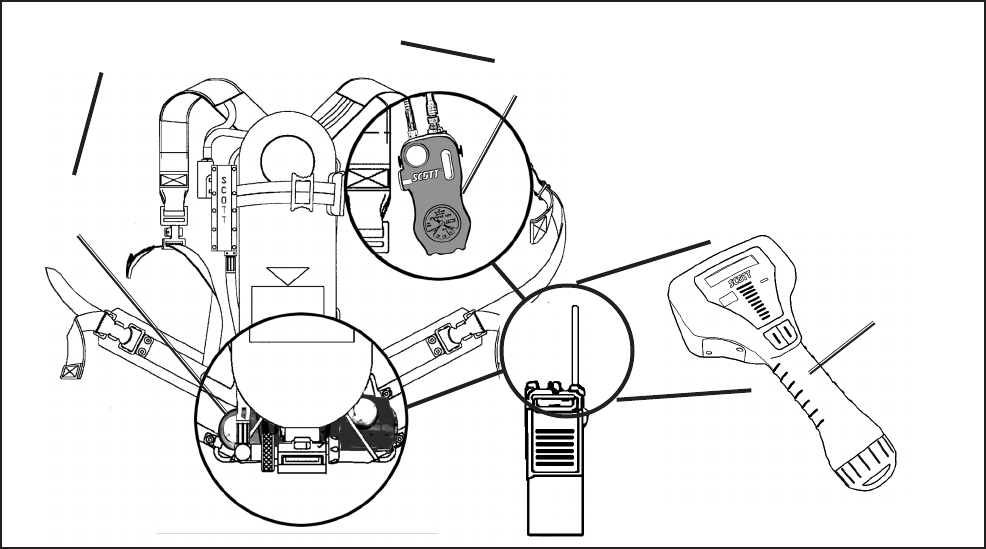
Page 35 of 40 P/N 595166-01 Rev A 1/09
DRAFT COPY
If the SEMS II distress alarm is affected by RFI when the respirator air supply
is turned off or the cylinder is empty, the distress alarm could be turned off
during use. If this occurs, depress the RED Manual Alarm Button to activate
the alarm.
IF THE SYMPTOMS OF RFI OCCUR, THE RESPIRATOR USER MUST
CHECK THE SEMS II DISTRESS ALARM TO VERIFY THAT IT IS FUNC-
TIONING PROPERLY. IF THE GREEN LIGHT ON THE CONTROL CONSOLE
DOES NOT RESUME FLASHING IN THE NORMAL MANNER AFTER EX-
PERIENCING THE SYMPTOMS OF RFI, OR IF THE UNIT CONTINUES
TO MALFUNCTION IN ANY OTHER WAY, PROCEED TO A SAFE AREA,
REMOVE THE RESPIRATOR FROM SERVICE AND TAG FOR REPAIR BY
AUTHORIZED PERSONNEL.
Minimize or eliminate the effects of RFI by protecting the PAK-ALERT with
the following steps:
– Maintain a safe distance from a base station transmitting antenna or a
truck mounted radio antenna.
– Keep the antennas of hand held radios at least six (6) inches away from the
CONTROL CONSOLE or the SENSOR MODULE. See FIGURE 5.
RFI AND THE PAK-TRACKER HAND HELD RECEIVER
If the Hand Held Receiver experiences RFI, it may be necessary to remove
the Hand Held Receiver from service. In a known safe, non-hazardous
area, remove and reinstall the batteries to reset the unit (see the BATTERY
REPLACEMENT section of the PAK-TRACKER Locator System User
Instructions, SCOTT P/N 595102-01). Then inspect and return the Hand Held
Receiver to service.
HAND HELD
RECEIVER
FIGURE 5
RFI WARNING AREAS
SENSOR
MODULE
CONTROL
CONSOLE
KEEP RADIO ANTENNAS AT LEAST
SIX (6) INCHES FROM THESE AREAS

Page 36 of 40
P/N 595166-01 Rev A 1/09
DRAFT COPY
WARNING
RADIO FREQUENCY INTERFERENCE (RFI)
MAY CAUSE A MALFUNCTION OF THE SEMS
II PDA DISTRESS ALARM. USERS OF RES-
PIRATORS EQUIPPED WITH THE SEMS II
PDA DISTRESS ALARM MUST BE AWARE
OF THE PROPER OPERATION OF THE DIS-
TRESS ALARM. FAILURE TO RECOGNIZE
A MALFUNCTION OF THE EQUIPMENT AND
TAKE PROPER CORRECTIVE ACTION MAY
RESULT FAILURE OF THE SEMS II PDA DIS-
TRESS ALARM AND LEAD TO SERIOUS INJURY
OR DEATH.
FCC NOTICE
This equipment has been tested and found to comply with the require-
ments of United States Federal Communications Commission, Code of
Federal Regulations, FCC title 47, part 90 Section 20, limitation (27) and
requirement Part 90.238 over frequency range 453.0375 to 465.6375
MHz, as well as FCC Section 1.1310 for Occupational/Controlled Expo-
sure limits.
If the SEMS II Base Station or Portable Unit has been damaged, DO
NOT use this equipment. Maintenance or repair of this equipment must
only be performed by an authorized SCOTT service center. Unauthorized
service may void the manufacturers warranty and may cause damage to
the equipment. Use only Scott authorized accessories, cables, and power
connectors. Consult the operating and service manuals for instructions
on battery replacement, battery maintenance, and use of accessory
cables.
SAFETY LISTINGS
FCC COMPLIANCE
FCC Compliance Statement (Part 15.19)
This device complies with Part 15 of the FCC Rules. Operation is subject to
the following two conditions:
1. This device may not cause harmful interference, and
2. This device must accept any interference received,
Including interference that may cause undesired operation.
FCC Warning (Part 15.21)
Changes or modications not expressly approved by the party responsible for
compliance could void the user’s authority to operate the equipment.
This portable transmitter with its antenna complies with FCC’s RF exposure
limits for general population / uncontrolled exposure.
The Pak-Tracker Locator Integrated Transmitter has been assigned FCC ID
# T5E200451.
The SEMS II Control Console Transmitter has been assigned FCC ID
# T5E200729.
RADIO FREQUENCY INTERFERENCE (RFI)
When any electronic device is adversely affected by radio waves, Radio
Frequency Interference (RFI) is said to have occurred. All electronic de-
vices like the SEMS II distress alarm may be subject to the effects of RFI,
most of which are temporary in nature. Users of the SCOTT SCBA with the
integrated SEMS II distress alarm must be familiar with the normal operation
of the distress alarm and must also be familiar with how to identify and avoid
the effects of RFI (see DETECTING AND AVOIDING RADIO FREQUENCY
INTERFERENCE on page 6). If RFI occurs to the SEMS II distress alarm, it
may be caused by transmissions from hand-held or personal radios where the
radio antenna is touching or very close to (less than 6 inches from) components
of the SEMS II distress alarm. It may also be caused by transmissions from
base stations or high-powered vehicle mounted radios or any other powerful
source of electromagnetic radiation.
Page 37 of 40 P/N 595166-01 Rev A 1/09
DRAFT COPY
INDUSTRY CANADA COMPLIANCE
Industry Canada Statement
The term “IC” before the certication / registration number only signies that
the Industry Canada technical specications were met.
Section 14 of RSS-210
The installer of this radio equipment must ensure that the antenna is located
or pointed such that it does not emit RF eld in excess of Health Canada limits
for the general population. Consult Safety Code 6, obtainable from Health
Canada’s web site: www.hc-sc.gc.ca/rpb.
Operation is subject to the following two conditions:
1) this device may not cause interference, and
2) this device must accept any interference, including interference
that may cause undesired operation of the device.
CLASS B DIGITAL DEVICE
Note: This equipment has been tested and found to comply with the limits for
a Class B digital device, pursuant to Part 15 of the FCC Rules. These limits
are designed to provide reasonable protection against harmful interference
in a residential installation. This equipment generates, uses and can radiate
radio frequency energy and, if not installed and used in accordance with
the instructions, may cause harmful interference to radio communications.
However, there is no guarantee that interference will not occur in a particular
installation. If this equipment does cause harmful interference to radio or
television reception, which can be determined by turning the equipment off
and on, the user is encouraged to try to correct the interference by one or
more of the following measures:
– Reorient or relocate the receiving antenna
– Increase the separation between the equipment and receiver.
– Connect the equipment into an outlet on a circuit different from that to
which the receiver is connected.
– Consult the dealer or an experienced radio/TV technician for help.

Page 38 of 40
P/N 595166-01 Rev A 1/09
DRAFT COPY
SAFETY LISTINGS Continued...
INTRINSICALLY SAFE LISTING
The SEMS II distress alarm with Integrated Locator transmitter, Model Number
200451-SERIES, when installed on a SCOTT respirator, is listed as intrinsi-
cally safe per ANSI/UL Std. UL-913 in Class I, Division 1 Groups C and D
hazardous locations by SGS U. S. TESTING COMPANY, Inc. Only when
powered by the batteries listed in this instruction or indicated on the label on
the sensor module.
To maintain Intrinsic Safety Listing, inspect the respirator with SEMS II dis-
tress alarm regularly per the Regular Operational Inspection procedures in
this instruction. Substitution of Components May Impair Intrinsic Safety.
To reduce the risk of ignition of a ammable atmosphere, batteries must
only be changed in an area known to be nonammable. To reduce the risk
of explosion, use only the approved batteries, do not mix old batteries with
unused batteries, or mix batteries from different manufacturers.
HAND HELD RECEIVER
NON-INCENDIVE LISTING
The SCOTT PAK-TRACKER LOCATOR SYSTEM Hand Held Receiver P/N
200397-02 is listed by SGS U. S. TESTING COMPANY, Inc. as Non-Incendive
per ANSI/UL Std. UL-1604 for use in Class I Division 2 Groups A, B, C, and
D hazardous locations. Temperature Code T4 (-25° C to 85° C). To maintain
the Non-Incendive Listing, the equipment must be inspected regularly per the
following Regular Operational Inspection procedures. Do not tamper with or
substitute components in any manner. Use only SCOTT Battery Pack P/N
200402-02. Open the battery compartment only in an area known to be free
of ammable or explosive hazards.
WARNING – Substitution of Components May Impair the Non-Incendive
Listing. To reduce the risk of ignition of a ammable atmosphere, battery must
only be changed in an area known to be nonammable. Do not substitute any
other battery or power source.
WARNING
IF THE SEMS II DISTRESS ALARM IS USED
IN AN AREA OF EXPLOSIVE OR FLAMMABLE
HAZARDS, FAILURE TO REGULARLY INSPECT
AS INSTRUCTED, FAILURE TO CORRECT DAM-
AGE BEFORE USE, OR THE INSTALLATION OF
INCORRECT BATTERIES MAY LEAD TO A FIRE
OR EXPLOSION WHICH MAY RESULT IN PER-
SONAL INJURY OR DEATH.
WARNING
FAILURE TO REGULARLY INSPECT THE HAND
HELD RECEIVER AS DESCRIBED IN THIS IN-
STRUCTION OR FAILURE TO CORRECT ANY
DAMAGE FOUND, MAY IMPAIR THE SAFETY OF
THE EQUIPMENT. THE INSTALLATION OF IN-
CORRECT BATTERY OR SUBSTITUTION OF ANY
OTHER COMPONENTS MAY IMPAIR THE SAFETY
OF THE EQUIPMENT. IF THE EQUIPMENT IS
USED IN AN EXPLOSIVE OR FLAMMABLE AT-
MOSPHERE, IMPAIRING THE SAFETY OF THE
UNIT MAY LEAD TO A FIRE OR AN EXPLOSION
WHICH COULD RESULT IN SERIOUS INJURY
OR DEATH.
WARNING
REPLACE BATTERY PACK ONLY WITH SCOTT
BATTERY PACK, PART NO. 200402-02. DO NOT
REMOVE, RE-CHARGE, OR REPLACE BATTERY
PACK WHILE THE DEVICE IS IN A HAZARD-
OUS LOCATION. REMOVING, RE-CHARGING,
OR REPLACING THE BATTERY PACK WHILE
THE DEVICE IS IN A HAZARDOUS LOCATION
MAY LEAD TO A FIRE OR AN EXPLOSION
WHICH COULD RESULT IN SERIOUS INJURY
OR DEATH.

Page 39 of 40 P/N 595166-01 Rev A 1/09
DRAFT COPY
Report any operational malfunctions of the PASS function of this device
to the certication agency Safety Equipment Institute (SEI), 1307 Dolley
Madison Blvd. Suite 3A, McLean, VA 22101, (703) 442-5732, FAX (703)
442-5756.
SEMS II DISTRESS ALARM
PERFORMANCE SPECIFICATIONS
Sound Levels:
Pre-Alarm... ......................... 70 to 105 dBA incrementally at left ear
Full-Alarm ............................ 95 to 100 dBA @ 9.9 Ft. (3m)
Frequency Range ............... 1.5 KHz to 4 KHz
Battery Life (fresh batteries)
Alkaline Batteries:
Automatic (green ashing light, no sound) ..............Approx. 1000 hours
Full Alarm (red ashing light, 95 dBA sound)....... . Approx. 8 hours
Compliance
The SCOTT SEMS II distress alarm is a NIOSH approved accessory for
use on only the following SCOTT SCBA respirators:
(NIOSH approval numbers have been included for identication):
SCOTT 2.2 AIR-PAK (30 min.) TC-13F-80
SCOTT 3.0 AIR-PAK (30 min.) TC-13F-366
SCOTT 4.5 AIR-PAK (30 min.) TC-13F-76
SCOTT 4.5 AIR-PAK (45 min.) TC-13F-212
SCOTT 4.5 AIR-PAK (60 min.) TC-13F-96
NOTE
DO NOT USE A FIBERGLASS WRAPPED ONE HOUR CYLINDER ON A
MODEL 4.5 AIR PAK EQUIPPED WITH A SEMS II DISTRESS ALARM AS
THE WEIGHT WILL EXCEED THE 35 LBS APPROVAL LIMIT FOR SCBA’s
ESTABLISHED BY NIOSH.
QUESTIONS OR CONCERNS
If you have any questions or concerns regarding use of this equipment, contact
your authorized SCOTT distributor, or contact SCOTT at 1-800-247-7257 (or
704-291-8300 outside the continental United States) or visit our web site at
www.scotthealthsafety.com.
PERSONAL COMPUTER
The personal computer Base Station environmental operating parameters
are totally dependant on the limitations of the personal computer used
with the SCOTT SEMS II Accountability System PCMCIA card. Do not
use the personal computer Base Station in environments for which it is
not designed. Handle the personal computer according to the instructions
provided with the personal computer.
EXPORT AND IMPORT
The SCOTT SEMS II Accountability System and portions thereof are regis-
tered under United States export regulations and under the import regulations
of most countried. If you have any questions or concerns regarding these
regulations, contact SCOTT at 1-800-247-7257 (or 704-291-8300 outside the
continental United States).

Page 40 of 40
P/N 595166-01 Rev A 1/09
DRAFT COPY
Health & Safety Products
Monroe Corporate Center
PO Box 569
Monroe, NC 28111
Telephone 1-800-247-7257
FAX (704) 291-8330
www.scotthealthsafety.com
Printed in USA
NOTICE:
THESE USER INSTRUCTIONS
ARE TO BE REMOVED ONLY
BY THE END USER.
QUESTIONS OR CONCERNS
If you have any questions or concerns regarding use of this equipment, contact
your authorized SCOTT distributor, or contact SCOTT at 1-800-247-7257 (or
704-291-8300 outside the continental United States) or visit our web site at
www.scotthealthsafety.com.