3M Scott Technologies 201122A X3 SEMS + BT User Manual 595289 01 A
Scott Safety-Division of Scott Technologies, Inc. X3 SEMS + BT 595289 01 A
Users Manual B Draft Rev

Page 1 of 36
P/N 595289-01 Rev B 5/15
OPERATION AND MAINTENANCE INSTRUCTIONS
SEMS II
SCOTT ELECTRONIC MANAGEMENT SYSTEM
USER PERSONAL DISTRESS ALARM AND USER ACCOUNTABILITY SYSTEM
FOR THE SCOTT AIR-PAK X3 SELF-CONTAINED BREATHING APPARATUS
SEMS II CONSOLE ON AIR-PAK X3 SCBA
WARNING
THE SCOTT SEMS II PERSONAL DISTRESS ALARM AND USER ACCOUNTABILITY SYSTEM IS INTENDED
FOR USE WITH SCOTT SELF-CONTAINED BREATHING APPARATUS (SCBA) WHICH MAY SUPPORT HUMAN
LIFE IN HAZARDOUS ATMOSPHERES. FAILURE TO CAREFULLY READ AND UNDERSTAND THE FOLLOWING
INSTRUCTIONS MAY RESULT IN SERIOUS INJURY OR DEATH TO THE SCBA USER.
USE OF A RESPIRATOR INTEGRATED WITH THE SEMS II / BLUETOOTH USER ACCOUNTABILITY SYSTEM WILL
REQUIRE MODIFICATION OF THE RESPIRATOR "REGULAR OPERATIONAL INSPECTION PROCEDURES" AND
WILL REQUIRE TRAINING OF THE RESPIRATOR USER IN THE USE OF SUCH RESPIRATORS.
THE FOLLOWING INSTRUCTIONS SUPPLEMENT BUT DO NOT REPLACE THE OPERATING AND MAINTENANCE
INSTRUCTIONS SUPPLIED WITH EACH RESPIRATOR.
© 2015 Scott Safety. SCOTT, the SCOTT SAFETY Logo, Scott Health and Safety, SEMS II, PAK-ALERT, PAK-TRACKER, AIR-
PAK, and NxG are registered and/or unregistered marks of Scott Technologies, Inc. or its afliates.
DRAFT COPY - NOT FOR PUBLICATION
IMPERIUM ACCOUNTABILITY
BASE STATION (SHOWN
WITH REQUIRED PERSONAL
COMPUTER, NOT INCLUDED)
WARNING
THIS PRODUCT IS DESIGNED AND INTENDED TO FUNCTION PROPERLY IN REASONABLE/ORDINARY FIREFIGHT-
ING CONDITIONS. IT HAS BEEN CERTIFIED TO THE STANDARDS CONTAINED IN THE 2013 EDITION OF NFPA
1982. LIKE ALL EQUIPMENT, THE FUNCTIONALITY OF THIS PRODUCT MAY BE COMPROMISED BY EXTREME
FIRE CONDITIONS.
PRELIMINARY DRAFT - NOT FOR PUBLICATION
Page 2 of 36
P/N 595289-01 Rev B 5/15
WARNING
DO NOT OPERATE THIS EQUIPMENT WHILE UN-
DER THE INFLUENCE OF DRUGS, ALCOHOL, OR
ANY MEDICATIONS OR SUBSTANCES WHICH
MAY AFFECT VISION, DEXTERITY, OR JUDG-
MENT. USERS OF THIS EQUIPMENT MUST BE
IN GOOD PHYSICAL AND MENTAL HEALTH IN
ORDER TO OPERATE SAFELY. DO NOT USE THIS
EQUIPMENT WHEN FATIGUE PREVENTS SAFE
OPERATION. STAY ALERT WHEN OPERATING
THIS EQUIPMENT. INATTENTION OR CARELESS-
NESS WHILE OPERATING THIS EQUIPMENT MAY
RESULT IN SERIOUS INJURY OR DEATH.
SYSTEM DESCRIPTION
SEMS II ACCOUNTABILITY SYSTEM
The SCOTT Electronic Management System (SEMS II) is a respirator user
accountability system that provides communication between respirator users in a
hazardous area and an incident commander or other designated person outside of the
hazardous area. The SCOTT SEMS II Personal Distress Alarm (PDA) is an optional
accessory. It is intended to be integrated only with a compatible SCOTT self-contained
breathing apparatus (SCBA) such as the AIR-PAK SCBA. The installation of the SCOTT
SEMS II Personal Distress Alarm is approved by the National Institute of Occupational
Safety and Health (NIOSH) on specic models of SCOTT SCBA.
The complete SCOTT Emergency Management System (SEMS) consists of:
• The Personal Alert Safety System (PASS) on the SCBA to sound a loud alarm
when the user is motionless for a short period of time;
• The IMPERIUM software with computer Base Station monitoring the status of
SCBA users, including air supply levels, PASS activation, and evacuation calls.
–Max. of 150 SCBAs using SEMS II
–Max. of 50 SCBAs using BLUETOOTH® backup
• The PAK-TRACKER Locator System to locate the transmitted signal from
a SEMS II Personal Distress Alarm (PDA) Portable Unit where PASS has
been activated.
The complete IMPERIUM ACCOUNTABILITY SYSTEM consists of:
• Individual transmitting SEMS II (or SEMS II with a BLUETOOTH backup)
enabled portable unit with Control Consoles integrated into to the SCOTT
self-contained breathing apparatus;
• Programmable ID Tags and programming equipment, (Tags are available in
a variety of forms);
• A Personal Computer (not included) with IMPERIUM software installed;
• Receiver(s) to capture transmitted SEMS II and BLUETOOTH signals to
personal computer.
Refer to the SCOTT CONNECT IMPERIUM ACCOUNTABILITY BASE STATION
SOFTWARE Installation and Use instructions, SCOTT P/N 595290-01, in the HELP
directory of the IMPERIUM software for a complete listing of all equipment available
for the IMPERIUM ACCOUNTABILITY SYESTEM. All items are sold separately.
SEMS II equipped PDA Portable Units provide a continuous limited two-
way communication between the SCBA respirator control console and
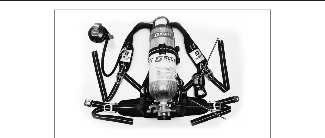
X3 AIR-PAK SCBA WITH SEMS II DISTRESS ALARM ASSEMBLY
SEMS II CONTROL
CONSOLE
ASSEMBLY
SENSOR MODULE
ASSEMBLY
SEMS II
SCOTT ELECTRONIC MANAGEMENT SYSTEM
PERSONAL DISTRESS ALARM AND BASE STATION
NOTE
USE IN ACCORDANCE WITH NFPA 1500,
"STANDARD ON FIRE DEPARTMENT
OCCUPATIONAL SAFETY AND HEALTH
PROGRAM."
The BLUETOOTH trademarks are owned by BLUETOOTH SIG, Inc. Other trademarks and trade names in this document are those of their respective
owners. © 2013 BLUETOOTH SIG, Inc. Subject to change without prior notice.
MOTOROLA and the Stylized M Logo are trademarks or registered trademarks of Motorola Trademark Holdings, LLC.

Page 3 of 36
P/N 595289-01 Rev B 5/15
WARNING
NO PERSONAL ALERT SAFETY SYSTEM,
RESPIRATOR OR COMBINATION OF PERSONAL
ALERT SAFETY SYSTEM AND RESPIRATOR,
BY THEMSELVES, CAN PROVIDE COMPLETE
PROTECTION IN DANGEROUS SITUATIONS.
FAILURE TO FOLLOW THE INSTRUCTIONS IN
THIS MANUAL AND THE REQUIREMENTS OF
AN ORGANIZED RESPIRATORY PROTECTION
PROGRAM MAY LEAD TO SITUATIONS WHICH
COULD RESULT IN SERIOUS INJURY OR DEATH.
WARNING
USERS OF RESPIRATORS EQUIPPED WITH THE
SEMS II DISTRESS ALARM MUST BE AWARE OF
THE PROPER OPERATION OF THE DISTRESS
ALARM. IF THE GREEN LIGHT IS NOT FLASHING
NORMALLY, OR IF THE UNIT EXHIBITS ANY
OTHER SIGNS OF A MALFUNCTION WITHOUT
THE USER TAKING PROPER CORRECTIVE
ACTION, IT MAY LEAD TO CIRCUMSTANCES
THAT RESULT IN SERIOUS INJURY OR DEATH.
SYSTEM DESCRIPTION
CONTINUED ON NEXT PAGE...
SEMS II PERSONAL DISTRESS ALARM CONTROL CONSOLE
The SCOTT SEMS II PDA Portable Unit, when added to a SCOTT SCBA respirator
consists of a Sensor Module with battery compartment mounted to the bottom of
the respirator backframe, a pressure gauge with transducer, and a Control Console
mounted on the wearer’s right shoulder strap at the pressure gauge location. The
SEMS II PDA Portable Unit requires six (6) AA batteries to operate the Sensor Module
on the backframe.
The SEMS II PDA Control Console is
integrated into the SCOTT SCBA as a
part of the remote air pressure gauge
assembly which hangs over the right
shoulder of the respirator user. The
Control Console also operates the
PERSONAL ALERT SAFETY SYSTEM
(PASS) distress alarm intended to as-
sist in locating a respirator user who is
incapacitated or in need of assistance.
The PASS distress alarm in this model
reaches FULL ALARM in a total of 30
(thirty) seconds. The Control Console
has a set of status lights, a dial air pres-
sure gauge, and three control buttons
which can easily be pressed with gloved
hands. Power is supplied by batteries in
the SEMS II PDA battery compartment
on the SCBA backframe.
WARNING
FOLLOW REGULAR OPERATIONAL INSPECTION
PROCEDURE EXACTLY. IF THE SEMS II
DISTRESS ALARM DOES NOT ACTUATE, OR IF
ANY OTHER FEATURE DOES NOT OPERATE AS
DESCRIBED OR IF ANY OTHER OPERATIONAL
MALFUNCTION IS NOTED, DO NOT USE THE
RESPIRATOR.
WARNING
THE SEMS II ACCOUNTABILITY SYSTEM
COMMUNICATES ONLY WITH FIREFIGHTER
RESOURCES (RESPIRATOR USERS) USING
A SCOTT SCBA EQUIPPED WITH THE SEMS
II ACCOUNTABILITY SYSTEM INTEGRATED
INTO THE PERSONAL DISTRESS ALARM.
OTHER FIREFIGHTER RESOURCES WHO ARE
NOT USING A PROPERLY EQUIPPED SCOTT
RESPIRATOR MAY BE ADDED FOR ACCOUNT-
ABILITY PURPOSES, BUT THEY WILL NOT BE
AUTOMATICALLY ACCESSIBLE THROUGH
THE COMMUNICATIONS FUNCTIONS OF THE
SYSTEM. FAILURE TO RECOGNIZE THE STATUS
OF FIREFIGHTER RESOURCES MAY RESULT IN
SERIOUS INJURY OR DEATH.
the IMPERIUM software. When logged on, all the SEMS II PDA Portable Units
communicate to the Base Station directly and/or through other logged on units forming
a communications "mesh network" to the Base Station. This extends the range for
the units furthest away from the Base Station. Because of this mesh network system,
the signal strength of each user may change as the network constantly re-adjusts to
the movement of the users.
SCBAs addtionally equipped with an optional BLUETOOTH backup communication,
provide a limited one-way transmission from the control console to the Base Station
at one minute intervals via a APX™ RF Modem/ Radio network. No information can
be transmitted back to the respirator user when transmitting in BLUETOOTH mode.
In units equipped with both SEMS II and BLUETOOTH, the SEMS II is the primary
mode of communication between the console and Base Station. BLUETOOTH will
only transmit information via radio to the base station when the SEMS II is out of
range or otherwise unable to link to the system. Once the SEMS II transmission has
resumed, or the SCBA is turned off, the BLUETOOTH transmission will discontinue.
SEMS II CONTROL CONSOLES
AIR-PAK X3
MODEL
CONSOLE
NOTE
SEMS II ENABLED PDA UNITS HAVE BIDIRECTIONAL COMMUNICATION CAPABILI-
TIES AND CAN BOTH TRANSMIT AND RECEIVE DATA BETWEEN THE PDA AND
THE BASE STATION. WHEN IN BLUETOOTH MODE, BLUETOOTH ENABLED PDA
CONTROL CONSOLES ARE UNIDIRECTIONAL ONLY. THEY CAN SEND DATA TO
THE BASE STATION THROUGH APPROVED BLUETOOTH ENABLED PORTABLE
TWO-WAY RADIOS BUT CANNOT RECEIVE DATA BACK FROM THE BASE STATION.
No personal alert safety system, respirator, or combination of personal alert safety
system and respirator, by themselves, can provide complete protection in dangerous
situations. However, using an alarm and a respirator in accordance with the require-
ments of an organized respiratory protection program is one of the many safety
precautions which should be taken to avoid personal injury or death.
These instructions explain the operation and use of the main functions of the ac-
countability system. Follow the REGULAR OPERATIONAL INSPECTION procedure
as described. If any function fails to operate as described, do not use the equipment.
Remove the unit from service and tag for repair by authorized personnel.
This system communicates only with Fireghter Resources (Respirator Users) using
a SCOTT SCBA equipped with the SEMS II Accountability System integrated into the
Personal Distress Alarm.
Complete training in the use of the SEMS II and Bluetooth equipment is required
before actual use in a hazardous envirionment. If the equipment does not work as
described in these instructions, remove the equipment from service and tag for repair
by authorized personnel.
Page 4 of 36
P/N 595289-01 Rev B 5/15
SYSTEM DESCRIPTION CONTINUED...
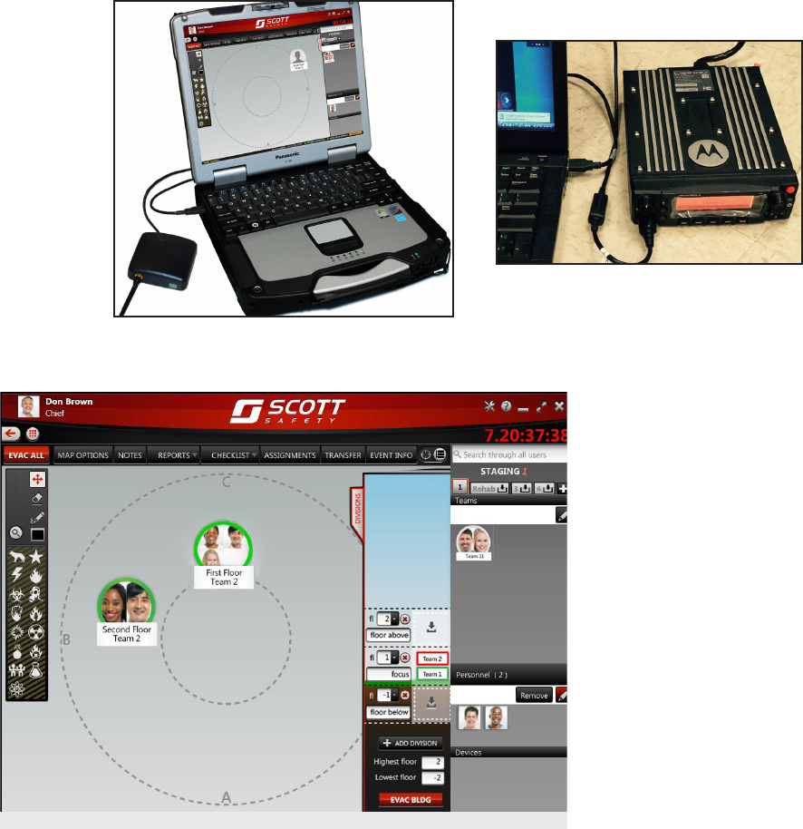
EXAMPLE OF IMPERIUM BASE STATION SCREEN DISPLAY
SEMS II ACCOUNTABILITY SYSTEM BASE STATION
The base station consists of a IMPERIUM Accountability Software, USB Gateway or
PCMCIA card SEMS II receiver, and/or optional APX RF Modem receiver installed on
a Windows1 based Personal Computer (not included). SCOTT recommends use of a
laptop computer designed for rugged use. Refer to the SCOTT CONNECT IMPERIUM
ACCOUNTABILITY BASE STATION SOFTWARE Installation and Use instructions,
SCOTT P/N 595290-01, in the HELP directory of the IMPERIUM software for complete
system specication details, set up and operation.
With the Imperium Event Management Software running on the PC, the incident com-
mander has current information about status of the respirator users who are logged
onto the Base Station, including information about air supply levels and PASS activa-
tion. Simple dedicated functions in the software control the transmission to (SEMS
II only) and receipt of signals from (SEMS II and BLUEtootth) respirator users. The
same computer can be used for programming the ID Tags used with the SEMS II PDA.
1 WINDOWS is a registered trademarks of MICROSOFT CORPORATION, Redmond, Washington
SEMS II BASE STATION WITH USB GATEWAY INSTALLED ON
A LAPTOP PERSONAL COMPUTER
WARNING
AUDIBLE ALARMS WILL ONLY SOUND FROM
THE BASE STATION WHILE BASE STATION
COMPUTER SPEAKERS ARE TURNED ON.
MUTING THE SPEAKERS WILL RENDER
THE BASE STATION ALARMS SILENT. BASE
STATION COMMANDER MUST NOT MUTE
THE BASE STATION SPEAKERS DURING AN
ACTIVE EVENT. FAILURE TO MONITOR AND
RESPOND TO AN ACTIVE ALARM COULD LEAD
TO SERIOUS INJURY OR DEATH.
APX RF MODEM
Page 5 of 36
P/N 595289-01 Rev B 5/15
When a respirator user opens the cylinder valve and begins use of a SCOTT SCBA
equipped with the SEMS II PDA, the Accountability System electronics will automati-
cally begin to operate. If the IMPERIUM Base Station is present at time of entry the
SEMS II PDA will attempt to log-in to the Base Station. BLUETOOTH enabled units
will attempt to log-in to the Base Station once the paired radio is turned on and they
are communicating. When the SEMS II is out of range or otherwise unable to link
to the system, the BLUETOOTH information will display on the base station. Once
the SEMS II transmission has resumed, or the SCBA is turned off, the BLUETOOTH
display will discontinue. It is the responsibility of the Incident Commanders from each
re company to coordinate activities with each other and to maintain accountability
for all participating reghter resources.
Multiple organizations with SEMS II Accountability System equipment can operate
at a single event scene since each Base Station operator can select and monitor
which users log in on their Base Station. Multiple base stations may also be used at
a single event to manage resources from several different re companies. SEMS II
users will appear in one base station at a time. The user can be rejected and connect
to an alternate base station.
BLUETOOTH signats transmit to a base station modem via radio. The BLUETOOTH
users will simultaneously appear on ALL base stations that are congured to the same
radio channel. BLUETOOTH units will continue to display on the base station screen
until the PDA unit either re-establishes SEMS II communication or it is turned off and
removed from the base station.
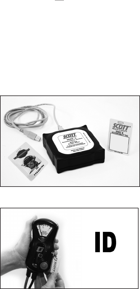
The SEMS II Accountability System and Personal Distress Alarm can be quickly pro-
grammed with the identication of the SCBA user using the SEMS II Accountability
RFID Tag, Badge, or Button. Programming the ID Tags and Portable Units allows
the organization to customize the identication of the SEMS II Portable Units. See
SEMS II Programming Guide, SCOTT Imperium Commissioning for complete details
of programming the SEMS II equipment. SCOTT recommends re-programming with
the RFID card in accordance with your organization's procedures to assure that the
user's unique ID number is in use at all times.
SYSTEM DESCRIPTION
CONTINUED ON NEXT PAGE...
PROGRAMMING THE USER ID WITH THE RFID TAG
ID ICON
SEMS II RFID TAG WRITER, SCOTT P/N 200773-01.

Page 6 of 36
P/N 595289-01 Rev B 5/15
PAK-TRACKER LOCATOR SYSTEM
The SCOTT PAK-TRACKER Locator System is a two part electronic system
consisting of a PAK-TRACKER Transmitter integrated into the SCOTT SEMS II
distress alarm, and a PAK-TRACKER Hand Held Receiver, which is a directional
receiver used to locate the signal coming from the PAK-TRACKER Transmitter. The
PAK-TRACKER locator system transmitter is activated with the PASS alarm. The
transmitter emits a radio signal with a unique ID number that can be tracked using
the SCOTT PAK-TRACKER Hand Held Receiver unit.
The PAK-TRACKER Hand Held Receiver is then used as a directional receiver to
assist in leading the rescue team to the activated transmitter. By pointing the PAK-
TRACKER Hand Held Receiver in the direction of the strongest relative signal, the
rescue crew can follow the signal toward the respirator user who is incapacitated or
in need of assistance.
Use of this equipment must be part of a complete personnel accountability system that
includes procedures for monitoring the deployment and condition of all users. Do not
rely on the PAK-TRACKER Locator System as the only technique for locating miss-
ing personnel. Failure to use this equipment properly may actually increase the time
needed to locate and rescue personnel. TRAINING AND PRACTICE IN REALISTIC
EMERGENCY SIMULATIONS IS REQUIRED BEFORE USE OF THIS EQUIPMENT.
The users must become thoroughly familiar with the operation and the limitations of
the locator system before entering a potentially hazardous or life threatening situation.
The PAK-TRACKER Locator System User Instructions, SCOTT part number 595102-
01, contain essential information on the use of the locator system and must be used as
the basis of training for use of the whole system including use with a SEMS II distress
alarm equipped with the PAK-TRACKER Transmitter. The PAK-TRACKER Locator
System User Instructions include an overview of the system operation, limitations of
the system, as well as any user level maintenance for the PAK-TRACKER Locator
System equipment. Copies of the PAK-TRACKER Locator System User Instructions
are available from your SCOTT distributor or from SCOTT Safety.
All User Instructions are provided on the software CD in Adobe Acrobat 2 format
(pdf). You may download a free copy of Adobe Acrobat Reader from www.Adobe.
com/Acrobat Reader.
PAK-TRACKER
HAND HELD RECEIVER
WARNING
READ AND UNDERSTAND THIS ENTIRE MAN-
UAL AND THE PAK-TRACKER LOCATOR
SYSTEM MANUAL, P/N 595102-01. TRAINING IS
REQUIRED BEFORE USE OF THIS EQUIPMENT
IN A HAZARDOUS SITUATION. THE TRAINING
MUST INCLUDE AN UNDERSTANDING OF THE
LIMITATIONS OF THE EQUIPMENT AND HOW TO
INTERPRET LOCATING INFORMATION, ALONG
WITH EXTENSIVE PRACTICE WITH THE SYSTEM
IN A VARIETY OF ENVIRONMENTS. USE OF THIS
EQUIPMENT MUST BE A PART OF A COMPLETE
PERSONNEL ACCOUNTABILITY SYSTEM.
ALWAYS UPDATE TRAINING WITH EACH NEW
PIECE OF EQUIPMENT. USE OF A PAK-TRACKER
LOCATOR SYSTEM WITHOUT PROPER TRAIN-
ING MAY PLACE THE USERS AT HIGHER RISK
IN DANGEROUS SITUATIONS WHICH COULD
RESULT IN SERIOUS INJURY OR DEATH.
SYSTEM DESCRIPTION CONTINUED...
2 Adobe and Adobe Acrobat are registered trademarks of Adobe Systems, San Jose, California

Page 7 of 36
P/N 595289-01 Rev B 5/15
DATA LOGGING FEATURE
Respirators equipped with a SCOTT SEMS II distress alarm integrated PASS device
are compliant to NFPA 1982, 2013 Edition. The PASS device includes on-board
electronics which maintain a running log of event data including start-up, shut-down,
and PASS activation. The SCOTT DATA LOGGER Computer Interface is required
to access the information. Instructions for downloading the data log are SCOTT P/N
595123-01 and are included with the computer interface.
RETROFITTED UNITS
Installation of the SCOTT SEMS II Personal Distress Alarm requires some disassem-
bly of the respirator and should only be performed by an authorized service center.
Respirators already equipped with an approved SCOTT X3 Distress Alarm integrated
PASS device may be retrotted with the SEMS II Accountability System Control Con-
sole. However, if the PAK-TRACKER Transmitter was NOT enabled on the original X3
Distress Alarm, this will have to be enabled by a SCOTT Authorized Service Center
to receive the full functionality described in these instructions.
Contact SCOTT Safety, Monroe, NC at 1-800-247-7257 for complete details.
Report any operational malfunctions of the PASS function of this device to the
certication agency Safety Equipment Institute (SEI), 1307 Dolley Madison Blvd.
Suite 3A, McLean, VA 22101, (703) 442-5732, FAX (703) 442-5756.
QUESTIONS OR CONCERNS
If you have any questions or concerns regarding use of this equipment, contact your
authorized SCOTT distributor, or contact SCOTT at 1-800-247-7257 (or 704-291-8300
outside the continental United States) or visit our web site at www.scottsafety.com.
Page 8 of 36
P/N 595289-01 Rev B 5/15
WARNING
THE INFORMATION BELOW IS MEANT TO
SUPPLEMENT, NOT REPLACE, THE TRAINING,
SUPERVISION, MAINTENANCE, AND
OTHER ELEMENTS OF YOUR ORGANIZED
RESPIRATORY PROTECTION PROGRAM.
SEE WARNING ON FIRST PAGE OF THIS
DOCUMENT. FAILURE TO COMPLY WITH THESE
INSTRUCTIONS MAY RESULT IN SERIOUS
INJURY OR DEATH.
WARNING
USERS OF RESPIRATORS EQUIPPED WITH
THE SEMS II DISTRESS ALARM MUST BE
AWARE OF THE PROPER OPERATION OF THE
DISTRESS ALARM. FAILURE TO RECOGNIZE
A MALFUNCTION OF THE SEMS II DISTRESS
ALARM AND TAKE PROPER CORRECTIVE
ACTION MAY RESULT IN SERIOUS INJURY OR
DEATH.
OPERATION AND USE OF THE SEMS II DISTRESS ALARM
(PASS)
ACTIVATION
Prepare the respirator for use according to the user instructions provided with the
respirator. Install the batteries in the SEMS II Sensor Module according to the BAT-
TERY INSTALLATION section of this instruction.
The SEMS II distress alarm device is automatically activated when the respirator is
pressurized by opening the cylinder valve of the respirator. To indicate activation, the
sensor module will sound 3 quick audible chirps and the green light located on the
control console will ash approximately once every three (3) seconds. The SEMS II
distress alarm is now in sensing mode.
Once activated, the SCOTT SEMS II distress alarm constantly monitors motion of
the respirator backframe. The sensor module is located on the respirator backframe
beneath the air cylinder and contains the motion sensor and the audible alarm. If the
sensor module does not sense motion of the respirator for twenty (20) seconds, the
SEMS II distress alarm will signal a pre-alarm condition. If there is still no motion of
the respirator for the next twelve (12) seconds the full alarm will sound.
The SCOTT SEMS II distress alarm will remain activated until turned OFF according
to these instructions.
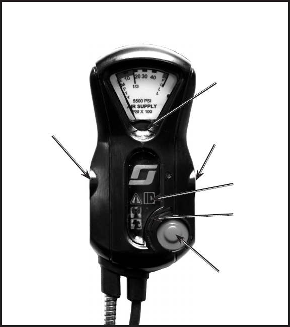
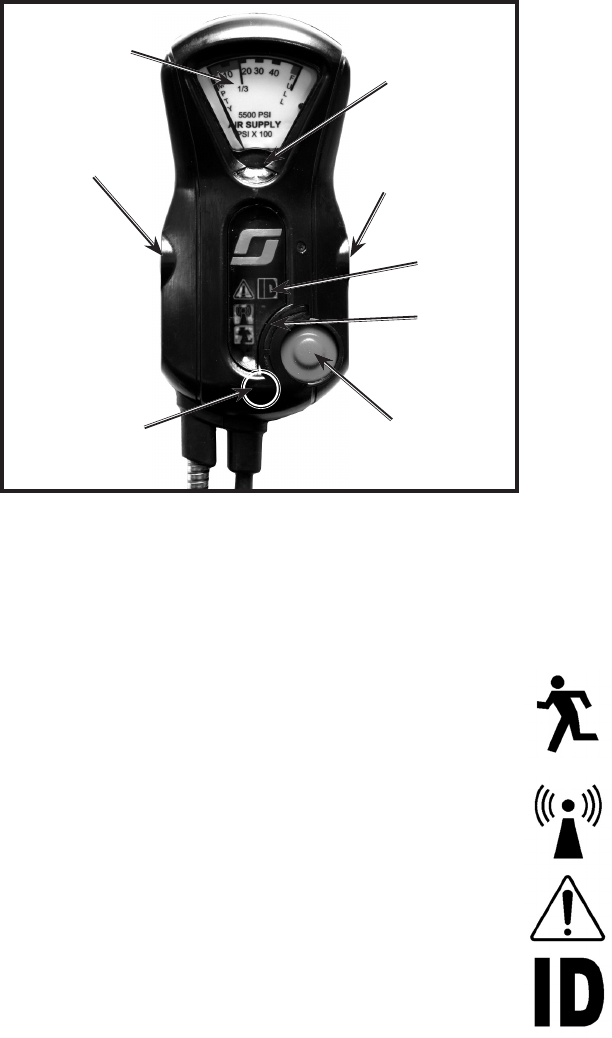
THE CONTROL CONSOLE
(PRESSURE GAUGE DEPENDS ON SYSTEM PRESSURE)
RESET BUTTON
(YELLOW BUTTON)
MANUAL ALARM
BUTTON
(RED BUTTON)
CONSOLE
DISPLAY
WITHDRAW
BUTTON
(GRAY BUTTON)
EXTERNAL-
HEADS UP
DISPLAY
(HUD)
AIR-PAK X3 MODEL
CONSOLE
PASS
SIGNAL
LIGHT

Page 9 of 36
P/N 595289-01 Rev B 5/15
WARNING
USERS OF RESPIRATORS EQUIPPED WITH
THE SEMS II DISTRESS ALARM MUST BE
AWARE OF THE PROPER OPERATION OF THE
DISTRESS ALARM. FAILURE TO RECOGNIZE
A MALFUNCTION OF THE SEMS II DISTRESS
ALARM AND TAKE PROPER CORRECTIVE
ACTION MAY RESULT IN SERIOUS INJURY OR
DEATH.
PRE ALARM:
If the respirator remains motionless for more than twenty (20) seconds, the SEMS II
distress alarm will automatically sound a pre-alarm
When the pre-alarm occurs, the green ashing light on the control console is replaced
by alternating bright red lights which ash approximately once a second and are
accompanied by an ascending/descending audible tone which increases in volume
during the pre-alarm cycle.
If the respirator user is not incapacitated or not in need of assistance, move the respi-
rator to reset the pre-alarm. When reset, the ashing red light will be replaced by the
ashing green and the ascending/descending tone will stop.
Remember that the motion sensor is in the sensor module on the respirator backframe
beneath the air cylinder. Actual movement of the respirator backframe is required to re-
set the pre-alarm. Shaking the control console will not reset the SEMS II distress alarm .
To manually reset the pre-alarm, press and hold the reset button on the side of the
control console until three (3) quick audible chirps are heard and the red ashing light
on the control console is replaced by the green ashing light.
FULL ALARM:
If the respirator remains motionless through the twelve (12) second pre-alarm cycle,
the SEMS II distress alarm will go into full alarm. This may indicate that the user is
incapacitated or in need of assistance and can not move.
Full alarm is indicated by a loud alarm tone from the sensor module accompanied by
simultaneous ashing red signal lights on the control console. After an additional (10)
second delay, the unit will send a notication of PASS activation to the SEMS II Base
Station and the Pak-Tracker Locator transmitter in the unit will begin transmitting the
unique ID number that can be received by the Pak-Tracker Hand Held Unit.
To reset the full alarm condition, press the reset button twice. After the full alarm
has been silenced, the SEMS II distress alarm will remain activated in sensing mode
with the green light ashing once per second. As long as the respirator is pressurized,
there must be movement of the respirator at least every twenty (20) seconds or the
distress alarm will again go into pre-alarm followed by full alarm as described above.
MANUAL ALARM:
If the respirator user requires immediate assistance, pressing the manual alarm button
located on the front of the control console will immediately sound the full alarm. The
manual alarm may be activated at any time, even when the respirator is not pressurized.
The manual alarm is indicated by a loud alarm tone from the sensor module accom-
panied by simultaneous ashing red signal lights on the control console. The unit will
immediately send a notication of PASS activation to the SEMS II Base Station and
the Pak-Tracker Locator transmitter in the unit will begin transmitting the unique ID
number that can be received by the Pak-Tracker Hand Held Unit.
.
To reset the manual alarm, press the reset button twice. After the alarm has
been silenced, the SEMS II distress alarm will remain activated in sensing mode.
To turn the unit off, press the reset twice again while the unit is not in alarm mode.
Remember, the loud audible alarm and ashing red light can be turned on at any time
by pressing the manual alarm button on the control console.
TO TURN OFF THE SEMS II DISTRESS ALARM
When use of the respirator with the SEMS II distress alarm is no longer required,
close the cylinder valve on the respirator and vent the residual air from the respirator
system by opening the regulator purge valve. After all the air ow stops, press the
reset button twice to turn off the distress alarm and close the regulator purge valve.
If there is no pressure in the system when the RESET button is pressed twice, the
unit will sound a quick two tone chirp to indicate that the alarm has been turned off.
If there is air pressure left in the system when the RESET button is pressed twice, the
sensor module will allow fteen (15) seconds to for the residual air to bleed from the
system. .A green light will ash and sensor will beep for fteen (15) seconds. Once
the air has completely bled from system, the unit will sound the quick two tone chirp
to indicate that the alarm has been turned off. If pressure remains in the respirator
after the fteen (15) seconds and/or the respirator cylinder valve remains open, alarm
sensor WILL NOT turn off and the distress alarm will return to sensing mode.
OPERATION AND USE OF THE
SEMS II DISTRESS ALARM
CONTINUED ON NEXT PAGE...

Page 10 of 36
P/N 595289-01 Rev B 5/15
If the respirator cylinder is turned off and depressurized without rendering the alarm
sensor inactive (pressing the RESET button twice), the distress alarm will continue to
monitor motion in sensing mode. This means that the distress alarm may be used to
monitor motion after the respirator is turned off and depressurized. Resetting the full
alarm after the respirator has been depressurized will not turn off the distress alarm.
After resetting the full alarm, press the RESET switch twice with no alarm condition
to turn off the distress alarm.
LOW BATTERY
In a low battery condition, the SEMS II distress alarm will produce a single audible
chirp from the sensor module once every two (2) seconds and the green light on the
control module will not ash.
In low battery condition, the SEMS II distress alarm will not emit the 3 beeps when
cylinder valve is activated.
While in low battery condition, the SEMS II distress alarm will continue to operate for
a period of time greater then the longest duration cylinder available for the respirator.
However, the batteries must be replaced before the respirator is used again. See the
BATTERY REPLACEMENT section of these instructions.
If batteries are completely discharged or have not been installed, there will be no light
or sound and the unit will not operate.
BATTERY TEST
When the SEMS II PDA is in the off condition (cylinder valve closed with no ashing
lights, the batteries in the entire system can be checked by depressing and holding
the RESET button on the console.
• A GREEN LED will illuminate on the Control Console, if there is sufcient bat-
tery power remaining,
• A RED LED indicates that the batteries are low and must be replaced before
the respirator is to be used again.
If a low battery message occurs, ALL batteries must be changed before the respirator
is used again. See the BATTERY REPLACEMENT section of this instruction for details.
WARNING
DO NOT USE A RESPIRATOR IN A LOW
BATTERY CONDITION. FAILURE TO REPLACE
THE BATTERIES AND/OR CONTINUING WITH
MULTIPLE USES OF THE RESPIRATOR AFTER
THE LOW BATTERY CONDITION HAS BEEN
INDICATED BY THE SEMS II DISTRESS ALARM
MAY RESULT IN FAILURE OF THE SEMS II
DISTRESS ALARM DURING USE AND POSSIBLE
INJURY OR DEATH OF THE USER.
OPERATION AND USE OF THE SEMS II DISTRESS ALARM
CONTINUED...
DATA LOGGING FEATURE
The SEMS II Distress Alarm PASS device includes on-board electronics which maintain
a running log of event data including start-up, shut-down, and PASS activation. The
SCOTT DATA LOGGER Computer Interface is required to access the information.
Instructions for downloading the data log are SCOTT P/N 595123-01 and are included
with the computer interface.
Use of the SCOTT DATA LOGGER Computer Interface will remove the programmed
RFID card number and will automatically return to the default ID number.
Page 11 of 36
P/N 595289-01 Rev B 5/15
CONSOLE BUTTONS
There are three (3) buttons on the Control Console. They are as follows:
MANUAL ALARM Red To activate the PASS alarm manually
WITHDRAW Gray To signal withdraw and scan ID card
RESET Yellow Used for various functions.
CONSOLE DISPLAY
The Console Display has four (4) ICON Symbol segments that light in response to
specic conditions. The four are:
EVAC
The EVAC symbol (Running Man) lights when either the Base Sta-
tion sends a call to the user(s) to EVACUATE (ashed RED), or the
user presses the WITHDRAW Button on the Control Console (ashes
YELLOW). Base Station call to evacute will not transmit to PDA when
communicating via BLUETOOTH.
RANGE
The RANGE symbol lights when the user is out of range of the Base
Station (SEMS II) or the APX radio (BLUETOOTH). The Base Station
displays a similar message.
PASS ALARM
The PASS ALARM symbol lights when the user’s PASS is activated.
The Base Station displays a similar message.
ID
The ID symbol is used to indicate the ID programming mode and that
the input from the user’s Accountability Tag has been accepted.
OPERATION AND USE OF ACCOUNTABILITY SYSTEM WARNING
TRAINING IS REQUIRED BEFORE USE OF THIS
EQUIPMENT IN A HAZARDOUS SITUATION.
USE OF THIS EQUIPMENT MUST BE A PART
OF A COMPLETE INCIDENT MANAGEMENT
AND PERSONNEL ACCOUNTABILITY SYSTEM
PROGRAM. THE TRAINING MUST INCLUDE
AN UNDERSTANDING OF THE LIMITATIONS
OF THE EQUIPMENT ALONG WITH EXTENSIVE
PRACTICE WITH THE SYSTEM IN A VARIETY OF
ENVIRONMENTS. ALWAYS UPDATE TRAINING
WITH EACH NEW PIECE OF EQUIPMENT. USE
OF THE SEMS II ACCOUNTABILITY SYSTEM
WITHOUT PROPER TRAINING MAY PLACE THE
USERS AT HIGHER RISK IN DANGEROUS SITU-
ATIONS WHICH COULD RESULT IN SERIOUS
INJURY OR DEATH.
The following section describes the features of the SEMS II Accountability System.
Training is required before use of this equipment. Use of this equipment must be part
of a complete incident management and personnel accountability program.
WARNING
THE SEMS II ACCOUNTABILITY SYSTEM
COMMUNICATES ONLY WITH FIREFIGHTER
RESOURCES (RESPIRATOR USERS) USING
A SCOTT SCBA EQUIPPED WITH THE SEMS
II ACCOUNTABILITY SYSTEM INTEGRATED
INTO THE PERSONAL DISTRESS ALARM.
OTHER FIREFIGHTER RESOURCES WHO ARE
NOT USING A PROPERLY EQUIPPED SCOTT
RESPIRATOR MAY BE ADDED FOR ACCOUNT-
ABILITY PURPOSES, BUT THEY WILL NOT BE
ACCESSIBLE THROUGH THE COMMUNICA-
TIONS FUNCTIONS OF THE SYSTEM. FAILURE
TO RECOGNIZE THE STATUS OF FIREFIGHTER
RESOURCES MAY RESULT IN SERIOUS INJURY
OR DEATH.
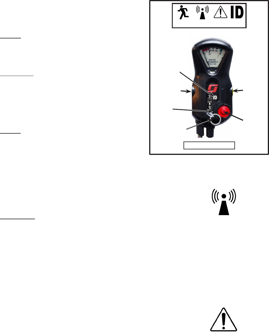
THE CONTROL CONSOLE
RESET BUTTON
(YELLOW BUTTON)
MANUAL ALARM
BUTTON
(RED BUTTON)
CONSOLE
DISPLAY
WITHDRAW
BUTTON
(GRAY BUTTON)
EXTERNAL-
HEADS UP
DISPLAY
(HUD)
PASS
SIGNAL
LIGHT
AIR
PRESSURE
GAUGE
OPERATION AND USE OF THE
ACCOUNTABILITY SYSTEM
CONTINUED ON NEXT PAGE...
NOTE
SEMS II ENABLED PDA UNITS HAVE BIDIRECTIONAL COMMUNICATION CAPA-
BILITIES AND CAN BOTH TRANSMIT AND RECEIVE DATA BETWEEN THE PDA
AND THE BASE STATION. BLUETOOTH ENABLED PDA CONTROL CONSOLES ARE
UNIDIRECTIONAL ONLY. THEY CAN SEND DATA TO THE BASE STATION THROUGH
APPROVED BLUETOOTH ENABLED PORTABLE TWO-WAY RADIOS BUT CANNOT
RECEIVE DATA BACK FROM THE BASE STATION.
BLUETOOTH
LED LIGHT
(BLUE)
Page 12 of 36
P/N 595289-01 Rev B 5/15
PROGRAMMING A UNIT WITH AN RFID TAG
SCOTT recommends re-programming with the RFID card in accordance with your
organization's procedures to assure that the user's unique ID number is in use at
all times. To program the identication of a SEMS II Portable unit with an RFID Tag,
proceed as follows:
1. Verify that the air cylinder is closed and there is no residual air in the system.
2. Verify that the electronics have been inactive for at lease thirty (30) seconds.
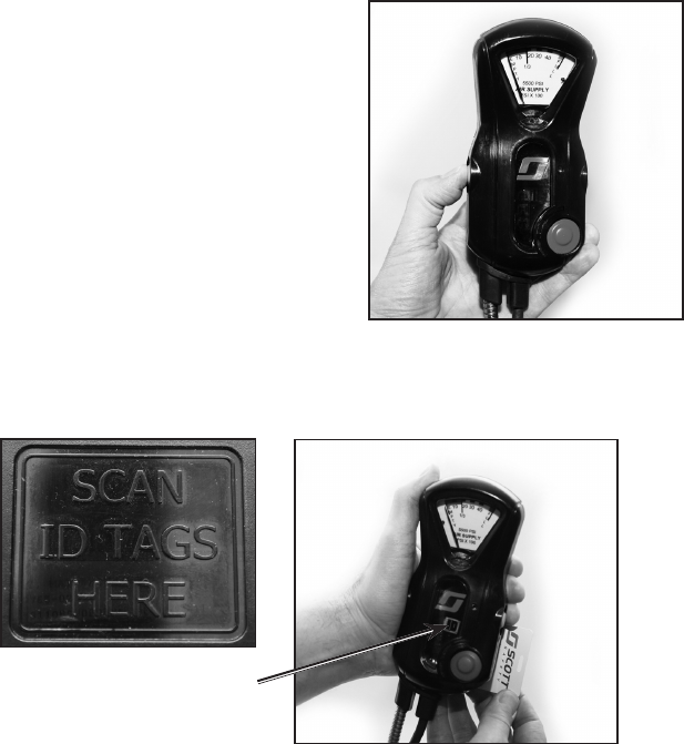
3. On the Control Console, hold down the GRAY (Withdraw) button until the ID light
goes on. Release the button.
4. Within ten (10) seconds, hold your SEMS II ID Tag against the back of the Control
Console labeled "SCAN ID TAGS HERE."
5. To indicate the programming has been successful, the ID light will ash three (3)
times slowly then go out.
6. When performing the REGULAR OPERATIONAL INSPECTION of the SEMS
II Accountability System, verify that the correct ID appears on the Base Station
display.
NOTE
ONCE THE RESPIRATOR HAS BEEN PRESSURIZED FOR USE, THE ID CANNOT
BE CHANGED. THE RESPIRATOR MUST BE SHUT DOWN AND THERE MUST
BE NO RESIDUAL AIR PRESSURE LEFT IN THE SYSTEM TO CHANGE THE ID.
To manually remove the programmed RFID card number, verify that the air cylinder is
closed, there is no residual air in the system, and the PASS is in the off state. Press
and hold the YELLOW RESET Button for eight (8) seconds. During reset, the red lights
on the PASS console will alternately ash and SEMS II Distress Alarm Pass device
will attempt to interface with Data Logger computer.
Additionally, the unit will automatically return to the default ID number:
– if the battery cover is opened and/or the batteries are removed,
OR
– after twenty-four (24) hours.
PRESSING THE GRAY (WITHDRAW)
BUTTON
PROGRAMMING THE USER ID WITH THE RFID TAG
ID LIGHT WILL FLASH 3
TIMES SLOWLY TO INDICATE
SUCCESSFUL PROGRAM
OPERATION AND USE OF ACCOUNTABILITY SYSTEM
CONTINUED...
Page 13 of 36
P/N 595289-01 Rev B 5/15
OPERATION AND USE OF THE
ACCOUNTABILITY SYSTEM
CONTINUED ON NEXT PAGE...
OPERATION AND USE OF PDA PORTABLE CONTROL
CONSOLE UNITS
Users of SCOTT respirators equipped with the SEMS II (and optional
BLUETOOTH enabled PDA) Control Consoles must be fully trained
in the operation of the equipment as part of a complete respiratory
protection program before entering a hazardous environment.
Start-up
• SEMS II: Use of the SEMS II enabled unit begins when the
user rst opens the cylinder valve on the respirator. The unit
will sound three chirps to indicate activation. After a brief start-
up sequence, the module will sound 3 quick audible chirps
and a green light located on the control console will ash
approximately once a second.
• BLUETOOTH: Use of the BLUETOOTH transmission begins
when a unit communicates with a previously paired compatible
portable two-way radio. Refer to the "PAIRING BLUETOOTH
ENABLED PDA CONTROL CONSOLE WITH PORTABLE
TWO-WAY RADIO" section of this instruction for pairing
instruction. To start the connection turn on the radio. Then,
open the cylinder. The LED light on the X3 console will begin
ashing BLUE as the PDA searches for the paired radio.
2. Initialization and RANGE
• SEMS II: After the start-up sequence, the SEMS II PDA Por-
table Unit will send an Initialization signal to the base station
a. When a SEMS II is searching for a connection to
the base station, the RANGE symbol on the Control
Console will flash YELLOW.
b. When a connection is made with the base station,
the RANGE symbol on the Control Console will turn
to solid GREEN
c. When a SEMS II respirator user loses contact with the base sta-
tion, the RANGE symbol on the Control Console will flash YELLOW
indicating out of range until it can regain contact. If using a dual
SEMS II and BLUETOOTH unit, the BLUETOOTH may connect
until SEMS II is back in range.
• BLUETOOTH:
a. When a Bluetooth connection is made to the two way radio the
LED on the PDA unit will light solid Blue.
b. When the SCBA user moves too far from the radio after logging-in,
the LED will flash BLUE until it is back in range.
Except for those functions which involve communication all PASS functions
of the Control Console and PDA distress alarm are still operational when the
Portable Unit is either out of range or not connected to a base station or radio.
3. PASS DISTRESS ALARM
a. The SEMS II PDA PASS distress alarm will operate in conjunc-
tion with the Portable Unit. If the distress alarm on the respirator
is activated, either by the user pressing and holding the Red
MANUAL ALARM button for at least two seconds, or from the user
being immobile for the required time duration, the Portable Unit
will send a PASS distress alarm signal to the base station. This
signal will override all other messages and actions of the Portable
Unit. The PASS symbol on the Control Console will flash RED.
(SEMS II and Bluetooth)
b. The PASS icon will appear Flashing RED on the Console, and an
audible alert will sound. (SEMS II and Bluetooth)
c. When the base station acknowledges the user’s distress signal
by selecting the TEAM Member's PASS button on the TEAM
Details, the PASS symbol on the Control Console will turn Solid
RED. (SEMS II ONLY)
d. The distress alarm on the respirator will continue until the user
shuts down the respirator or resets the alarm.
RANGE
PASS
EVAC
WITHDRAW
RANGE PASS ID
CONTROL CONSOLE ICONS
AIR-PAK X3
SIGNAL
LIGHTS
RESET
BUTTON
(YELLOW)
MANUAL ALARM
BUTTON
(RED)
WITHDRAW
BUTTON
(GRAY)
CONTROL
CONSOLE
DISPLAY
PDA PORTABLE CONTROL CONSOLE
BLUETOOTH
LED LIGHT
(BLUE)

Page 14 of 36
P/N 595289-01 Rev B 5/15
4. EVACUATION (SEMS II ONLY)
a. If the respirator users are required to leave the hazardous area,
the base station operator can send an evacuation message to the
Portable Units of logged-in respirator users. This message can be
sent either to all logged-in users (EVAC ALL), to everyone on an
Assignment (EVAC ASSIGN), to everyone in a geographic DIVISION
(EVAC BLDG) or to an individual logged-in users as selected from
the TEAM Details (EVAC).
b. The Portable Unit will emit the alert sound and the EVAC symbol will
begin flashing RED on the Control Console.
c. When an EVAC symbol begins flashing on the Control Console, the
respirator user must press twice the Yellow RESET button on the
Control Console to respond to the evacuation message. The EVAC
symbol on the Control Console will turn ON solid RED until the user
leaves the hazardous area and shuts down the respirator. The res-
pirator user's EVAC symbol in the TEAM Details on the Display will
change from RED to WHITE to indicate acknowledgement.
Evacuation message will ONLY be sent to individual SEMS II PDA users or to
the QUEUE interface. EVAC notice will not send to user while in BLUETOOTH
mode but will send once SEMS II communications have resumed. EVAC button
will be deactivated when no SEMS II Gateway is connected to the Base Station.
5. WITHDRAW
a. The respirator user may choose to leave the hazardous area. Pressing and
holding the Gray WITHDRAW button for at least two seconds will send that
message to the Base Station. The "EVAC" symbol on the Control Console
will ash YELLOW quickly as the WITHDRAW message appears on the Base
Station.
b. When the Base Station receives a user WITHDRAW message, the Base
Station Operator selects the ACK W/D button.
c) After the Base Station acknowledges, the “EVAC” symbol on the Control
Console will turn ON steady until user leaves hazardous area and shuts
down the respirator.
6. Air Supply Cylinder Pressure
a) In addition to the other end-of-service indicators on the respirator, when the
cylinder reaches one third of full pressure, the VIBE ALERT sounds a LOW
AIR warning with an audible alarm. .
b) The VIBE ALERT alarm will be transmitted until the respirator has been de-
pleted. This LOW AIR alarm is in addition to the other end-of-service indicators
on the respirator.
7. Shutdown
a) After leaving the hazardous area and conrming that respirator use is no
longer required, doff the respirator according the user instructions provided
with the respirator.
b) Close the cylinder valve. Use the purge valve to release all the residual air
pressure in the system.
c) Press the Yellow RESET button twice.
d) The Control Console will sound the alert tone. The SEMS II PDA Portable
Unit is now off.
EVAC/WITHDRAW
WARNING
THE RESPIRATOR USER MUST IMMEDI-
ATELY LEAVE THE AREA REQUIRING RE-
SPIRATORY PROTECTION WHEN AN END
OF SERVICE INDICATOR ALARM ACTU-
ATES. ACTUATION OF AN END OF SER-
VICE INDICATOR ALARM WARNS THAT
APPROXIMATELY 1/3 OF FULL PRESSURE
REMAINS IN THE AIR SUPPLY CYLINDER
(THAT IS, APPROXIMATELY 2/3 OF THE
TOTAL AIR SUPPLY HAS BEEN USED).
A DELAY IN LEAVING THE AREA AFTER
ALARM ACTUATION MAY CAUSE DEPLE-
TION OF BREATHING AIR SUPPLY WHICH
COULD RESULT IN SERIOUS INJURY OR
DEATH.
BASE STATION OPERATION
The SEMS II Base Station consists of a SEMS II Accountability System Base Station
installed in a Windows based Personal Computer, preferably a laptop (not included).
SCOTT recommends use of a laptop computer designed for rugged use.
Refer to the SCOTT CONNECT IMPERIUM ACCOUNTABILITY BASE STATION
SOFTWARE Installation and Use instructions, SCOTT P/N 595290-01, in the HELP
directory of the IMPERIUM software for complete details of computer requirements,
Base Station software setup, and use of the Accountability System.
The IMPERIUM Base Station must be operated by a fully trained individual as part
of a complete incident management system and respiratory protection program. The
Base Station Operator must have the ability to notify other personnel if an emergency
situation develops as displayed by the SEMS II Accountability System.
OPERATION AND USE OF ACCOUNTABILITY SYSTEM
CONTINUED...
WARNING
AUDIBLE ALARMS WILL ONLY SOUND FROM
THE BASE STATION WHILE BASE STATION
COMPUTER SPEAKERS ARE TURNED ON.
MUTING THE SPEAKERS WILL RENDER
THE BASE STATION ALARMS SILENT. BASE
STATION COMMANDER MUST NOT MUTE THE
BASE STATION SPEAKERS DURING AN ACTIVE
EVENT. FAILURE TO MONITOR AND RESPOND
TO AN ACTIVE ALARM COULD LEAD TO
SERIOUS INJURY OR DEATH.
EVAC/WITHDRAW

Page 15 of 36
P/N 595289-01 Rev B 5/15
WARNING
DO NOT TAKE THE BASE STATION INTO A FIRE
OR INTO A POTENTIALLY FLAMMABLE OR EX-
PLOSIVE ATMOSPHERE. OPERATE THE BASE
STATION ONLY IN A SAFE AREA AWAY FROM
THE HAZARDOUS ATMOSPHERE WHERE THE
RESPIRATORS ARE BEING USED. USE OF THE
BASE STATION IN A POTENTIALLY FLAMMABLE
OR EXPLOSIVE ATMOSPHERE MAY CAUSE IG-
NITION OF THE ATMOSPHERE WHICH COULD
RESULT IN SERIOUS INJURY OR DEATH.
WARNING
THE IMPERIUM ACCOUNTABILITY SYSTEM
COMMUNICATES ONLY WITH FIREFIGHTER
RESOURCES (RESPIRATOR USERS) USING A
SCOTT SCBA RESPIRATOR EQUIPPED WITH
THE IMPERIUM ACCOUNTABILITY SYSTEM
INTEGRATED INTO THE PERSONAL DISTRESS
ALARM. OTHER FIREFIGHTER RESOURCES
WHO ARE NOT USING A PROPERLY EQUIPPED
SCOTT RESPIRATOR MAY BE ADDED FOR
ACCOUNTABILITY PURPOSES, BUT THEY
WILL NOT BE AUTOMATICALLY ACCESSIBLE
THROUGH THE COMMUNICATIONS FUNC-
TIONS OF THE IMPERIUM SYSTEM. FAILURE
TO RECOGNIZE THE STATUS OF FIREFIGHTER
RESOURCES MAY RESULT IN SERIOUS INJURY
OR DEATH.
WARNING
THE IMPERIUM ACCOUNTABILITY BASE
STATION MUST BE MONITORED BY A FULLY
TRAINED INDIVIDUAL WITH THE ABILITY TO
DIRECT RESCUE OPERATIONS AT ALL TIMES
WHEN LOGGED-IN RESPIRATOR USERS MAY
BE IN A HAZARDOUS AREA. FAILURE TO
PROVIDE A PROPERLY TRAINED BASE STATION
OPERATOR MAY PERMIT A SITUATION TO
OCCUR WHICH COULD RESULT IN SERIOUS
INJURY OR DEATH.
PASSEVAC/WITHDRAW RANGE
PRIMARY FUNCTIONS OF THE SOFTWARE
IMPERIUM software is designed for both tactical and strategic event management
with compliance to NIMS and the user’s own organizational standard operating
guidelines (SOG’s).
The software is not SCBA specic and is designed to be used also by rst responders.
The primary purpose of the IMPERIUM is to monitor the activities of Accountability
System users, including active SEMS II PDA (Personal Distress Alarm) users and
Queue Accessory users, as well as Non-SEMS II PDA users (by use of RFID Tags to
log into the system) and Equipment.
The software is a TEAM Based approach to event management based on dened
ASSIGNMENTS and TEAMS placed on those assignments.
Each Event can be new or can be based on a customized set of parameters set in an
EVENT template. The Application Settings can also be preset to control the way the
Software displays and/or processes the information provided to the The IMPERIUM
Base Station Operator.
The primary functions of the software are as follows:
1. Open an EVENT.
2. Create ASSIGNMENTS for TEAMS.
3. ASSIGN Individual Resources to ASSIGNMENTS and TEAMS (and/or DIVISIONS
depending on the nature of the event.)
4. REJECT Individual Resources (active SEMS II PDA users, Bluetooth enabled
PDA users, NON-SEMS II PDA users and Equipment only.)
5. REMOVE Assignments, TEAMS, DIVISIONS, or Individuals from the event.
6. MONITOR the condition of active SEMS II and Bluetooth enabled PDA users and
take the appropriate actions.
7. Create NOTES for the event.
8. Provide a REPORT of the event.
Active SEMS II PDA users can send signals to and receive signals from the base
station. When in BLUETOOTH mode, PDA users can send signals to the base sta-
tion but cannot receive them from the base station. The base station operator can
perform the following tasks:
MONITOR ALERTS for:
• LOW AIR SUPPLY of each active SEMS II and BLUETOOTH enabled PDA user.
• PASS Activation (either automatic and manual activation) of each active SEMS
II and BLUETOOTH enabled PDA user.
• OUT-OF-RANGE – Shows the status of the communication link from each
User’s active SEMS II PDA (or QUEUE Interface) to the base station. (SEMS
II and QUEUE only)
• WITHDRAW Notication from each active SEMS II and BLUETOOTH enabled
PDA users.
Send an EVACUATION (EVAC) Signal when required (SEMS II PDA USERS ONLY):
• EVAC ALL – Evacuate all logged in active SEMS II only.
• EVAC TEAM – Evacuate a TEAM of logged in active SEMS II only.
• EVAC ASSIGNMENT– Evacuate by ASSIGNMENT of logged in active SEMS
II only.
• EVAC BLDG – Evacuate by DIVISION of logged in active SEMS II only.
• EVAC IND – Evacuate an Individual active SEMS II PDA users only.
NOTE
SEMS II PDA UNITS AND QUEUE ACCESSORIES CAN INITIALLY TAKE
APPROXIMATELY FORTY (40) SECONDS TO TWO (2) MINUTES TO CONNECT
TO THE BASE STATION. CONNECTION TIME MAY INCREASE AS THE NUMBER
OF ADDITIONAL NODES (EXTERNAL DEVICES) INCREASES.
NOTE
IF A PDA UNIT HAS BOTH SEMS II AND BLUETOOTH CAPABILITIES, THE SEMS
II WILL TRANSMISSIONS WILL ALWAYS TAKE PRECEDENCE AND APPEAR AS
A SEMS II USER ON THE BASE STATION. THE BLUETOOTH TRANSMISSION
WILL ONLY APPEAR AS A BLUETOOTH USER IF THE SEMS II TRANSMISSION
CANNOT CONNECT TO THE BASE STATION.
BASE STATION OPERATION
CONTINUED ON NEXT PAGE...
Page 16 of 36
P/N 595289-01 Rev B 5/15
WARNING
DO NOT TAKE THE BASE STATION INTO A
FIRE OR INTO A POTENTIALLY FLAMMABLE
OR EXPLOSIVE ATMOSPHERE. OPERATE THE
BASE STATION ONLY IN A SAFE AREA AWAY
FROM THE HAZARDOUS ATMOSPHERE WHERE
THE RESPIRATORS ARE BEING USED. USE
OF THE BASE STATION IN A POTENTIALLY
FLAMMABLE OR EXPLOSIVE ATMOSPHERE
MAY CAUSE IGNITION OF THE ATMOSPHERE
WHICH COULD RESULT IN SERIOUS INJURY
OR DEATH.
WARNING
THE IMPERIUM ACCOUNTABILITY SYSTEM
COMMUNICATES ONLY WITH FIREFIGHTER
RESOURCES (RESPIRATOR USERS) USING A
SCOTT SCBA RESPIRATOR EQUIPPED WITH
THE IMPERIUM ACCOUNTABILITY SYSTEM
INTEGRATED INTO THE PERSONAL DISTRESS
ALARM. OTHER FIREFIGHTER RESOURCES
WHO ARE NOT USING A PROPERLY EQUIPPED
SCOTT RESPIRATOR MAY BE ADDED FOR
ACCOUNTABILITY PURPOSES, BUT THEY
WILL NOT BE AUTOMATICALLY ACCESSIBLE
THROUGH THE COMMUNICATIONS FUNC-
TIONS OF THE IMPERIUM SYSTEM. FAILURE
TO RECOGNIZE THE STATUS OF FIREFIGHTER
RESOURCES MAY RESULT IN SERIOUS INJURY
OR DEATH.
The EVAC/WITHDRAW, PASS, and RANGE icons that appear on the software display
are the same as the EVAC/WITHDRAW, PASS, and RANGE symbols that appear on
the PDA Control Console display.
When active SEMS II PDA Users are logged into the system and included in the event
activities (moved to the MAIN TACTICAL DISPLAY), they must be part of a TEAM
and the TEAM must be associated with an ASSIGNMENT. As two individuals are as-
sociated with each other, they appear as a TEAM with ability to designate one of the
members as TEAM LEADER. If any member of a TEAM transmits an alert (PASS,
LOW AIR, or OUT-OF-RANGE), the TEAM icon on the screen will indicate RED and
an audible alarm will sound. The Alert information for the individual is available through
the TEAM Details.
When an ASSIGNMENT has been created and an individual is placed on the TACTI-
CAL VIEW Display Screen, that person will be labeled TEAM 1 and associated with
the current ASSIGNMENT. A TEAM should consist of a minimum of two (2) people. If
another individual is placed on the TACTICAL VIEW Display Screen but not associ-
ated with an existing TEAM, that individual will be labeled TEAM 2.
Additional functions include:
1. Accountability for Support Personnel (Non-SEMS II PDA Users by use of RFID
Tags to log into the system).
2. Personnel Accountability Report (PAR) Timer reminder can be set according to
your standard procedures.
3. Event Report to provide an account of event information.
NOTE
ACCESSIBILITY TO SOME SETTINGS MAY BE LIMITED BY YOUR SYSTEM
ADMINISTRATOR TO MAINTAIN COMPLIANCE WITH APPLICABLE NATIONAL
STANDARDS OR ESTABLISHED INTERNAL PROCEDURES.
TRAINING REQUIRED BEFORE USE. Refer to the SCOTT CONNECT IMPERIUM
ACCOUNTABILITY BASE STATION SOFTWARE Installation and Use instructions,
SCOTT P/N 595290-01, in the HELP directory of the IMPERIUM software for complete
details on the use of the IMPERIUM Accountability Base Station System.
BASE STATION OPERATION CONTINUED...
Page 17 of 36
P/N 595289-01 Rev B 5/15
BASE STATION OPERATOR RESPONSIBILITIES
The base station Operator must create and track ASSIGNMENTS.
The base station operator must monitor and respond to any ACTIVE ALERTS in
accordance with the organization’s event management program. This may include
issuing an EVAC signal to the individual or to the entire TEAM.
Monitor for the following TEAM MEMBER ACTIVE ALERTS including:
• LOW AIR
– When the air supply cylinder reaches predetermined pressure, the end-of-
service-time indicators (EOSTI) will activate on the SCBA and a LOW AIR
signal will be sent to the base station. The TEAM Icon will ash RED, the
"Team Summary" will show a red bar, the team member image of effected
individual in the "Teammate Details" will display a red bar and the base
station will sound the LOW AIR audible alarm.
• PASS
– When a User's PASS has been activated, the TEAM Icon will ash RED, the
"Team Summary" will show a red bar, the team member image of effected
individual in the "Teammate Details" will display a red bar and PASS icon,
and the base station will sound the PASS audible alarm. These alarms will
continue until the PASS has been turned off on the PDA unit.
• OUT OF RANGE
–The OUT OF RANGE caution will begin after forty (40) seconds without
a signal from the SEMS II PDA User or the QUEUE interface to the Base
Station, or two (2) minutes without transmission from BLUETOOTH enabled
PDA to the APX Radio. The TEAM Icon will ash YELLOW, the "Team
Summary" will show a yellow bar, the team member image in "Teammate
Details" will display a Yellow bar and Out of Range icon, and the base station
will sound the Out of Range caution audible alarm indicating the system is
trying to re-link with the user.
–If re-linking does NOT occur, the TEAM Icon will ash RED, the "Team Sum-
mary" will show a Red bar, the team member image in "Teammate Details"
will display a Red bar and Out of Range icon, and the base station will sound
the Out of Range audible alarm The base station operator must respond to
the User’s out of RANGE signal in accordance with the organization’s event
management program.
• WITHDRAW
– An individual TEAM Member chooses to WITHDRAW by pressing the GRAY
(or BLUE) button on the User’s Control Console on the SCBA. When this
occurs, the WITHDRAW message is sent to the base station. The TEAM
Icon will ash RED, the "Team Summary" will show a red bar, the team
member image of effected individual in the "Teammate Details" will display
a red bar and WITHDRAW icon, and the base station will sound the WITH-
DRAW audible alarm.
PAR CALL AND RESPONSE
• Support Personnel Accountability (Non-SEMS II PDA users by use of RFID
Tags to log into the system).
– The base station operator must monitor and coordinate the activities of Non-
SEMS II PDA users who have logged into the system by the use of RFID
Tags in accordance with the organization’s event management program.
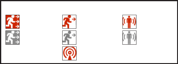
ALARM ICONS
Out of Range
Evacuate
Evacuation
Acknowledged
Withdraw
Withdraw
Acknowledged
PASS Alarm
PASS Alarm
Acknowledged
WARNING
AUDIBLE ALARMS WILL ONLY SOUND FROM
THE IMPERIUM BASE STATION WHILE WORKING
WITHIN AN OPEN EVENT. NAVIGATION TO ANY
OTHER SCREEN WILL RENDER THE ALARMS
AT THE IMPERIUM BASE STATION SILENT. THE
IMPERIUM BASE STATION COMMANDER MUST
NOT NAVIGATE TO OTHER SCREENS DURING
AN ACTIVE EVENT. FAILURE TO MONITOR AND
RESPOND TO AN ACTIVE ALARM COULD LEAD
TO SERIOUS INJURY OR DEATH.
WARNING
SEMS II PDA UNITS AND THE QUEUE ACCES-
SORY WILL ONLY CONNECT TO THE IMPERIUM
BASE STATION WHILE WORKING WITHIN AN
OPEN EVENT. NAVIGATION TO ANY OTHER
SCREEN WILL TEMPORARILY DISCONNECT
THESE DEVICES AND THEIR ALARMS. UPON
RETURN TO THE EVENT, THE DEVICES WILL
HAVE TO REESTABLISH A CONNECTION AND
WILL NOT SHOW ANY VISUAL OR AUDIBLE
ALARMS FOR APPROXIMATELY 2 MINUTES
UNTIL CONNECTION IS REESTABLISHED.
COMMANDER MUST NOT NAVIGATE TO OTHER
SCREENS DURING AN ACTIVE EVENT. FAILURE
TO MONITOR AND RESPOND TO AN ACTIVE
ALARM COULD LEAD TO SERIOUS INJURY
OR DEATH.
Page 18 of 36
P/N 595289-01 Rev B 5/15
USE AS PART OF AN ACCOUNTABILITY SYSTEM
TRAINING REQUIRED BEFORE USE. Refer to the PAK-TRACKER Locator Sys-
tem User Instructions, SCOTT P/N 595102-01 for complete details on the use of the
PAK-TRACKER Locator System. Use of this equipment must be part of a complete
personnel accountability system that includes procedures for monitoring the deploy-
ment and condition of all users. Do not rely on the PAK-TRACKER Locator System
as the only technique for locating missing personnel. A Rapid Intervention or Rescue
team using the Hand Held Receiver must have a minimum of two (2) people. For their
own safety, the team members must pay attention to their surroundings at all times
while using the PAK-TRACKER Locator System.
The accountability system must include procedures for alerting the incident commander
and rescue teams when actuated transmitters or the missing personnel have been
found or when they have moved from their previous location. It is the responsibility of
the personnel accountability system to allow for such contingencies without exposing
individuals and teams to unnecessary dangers.
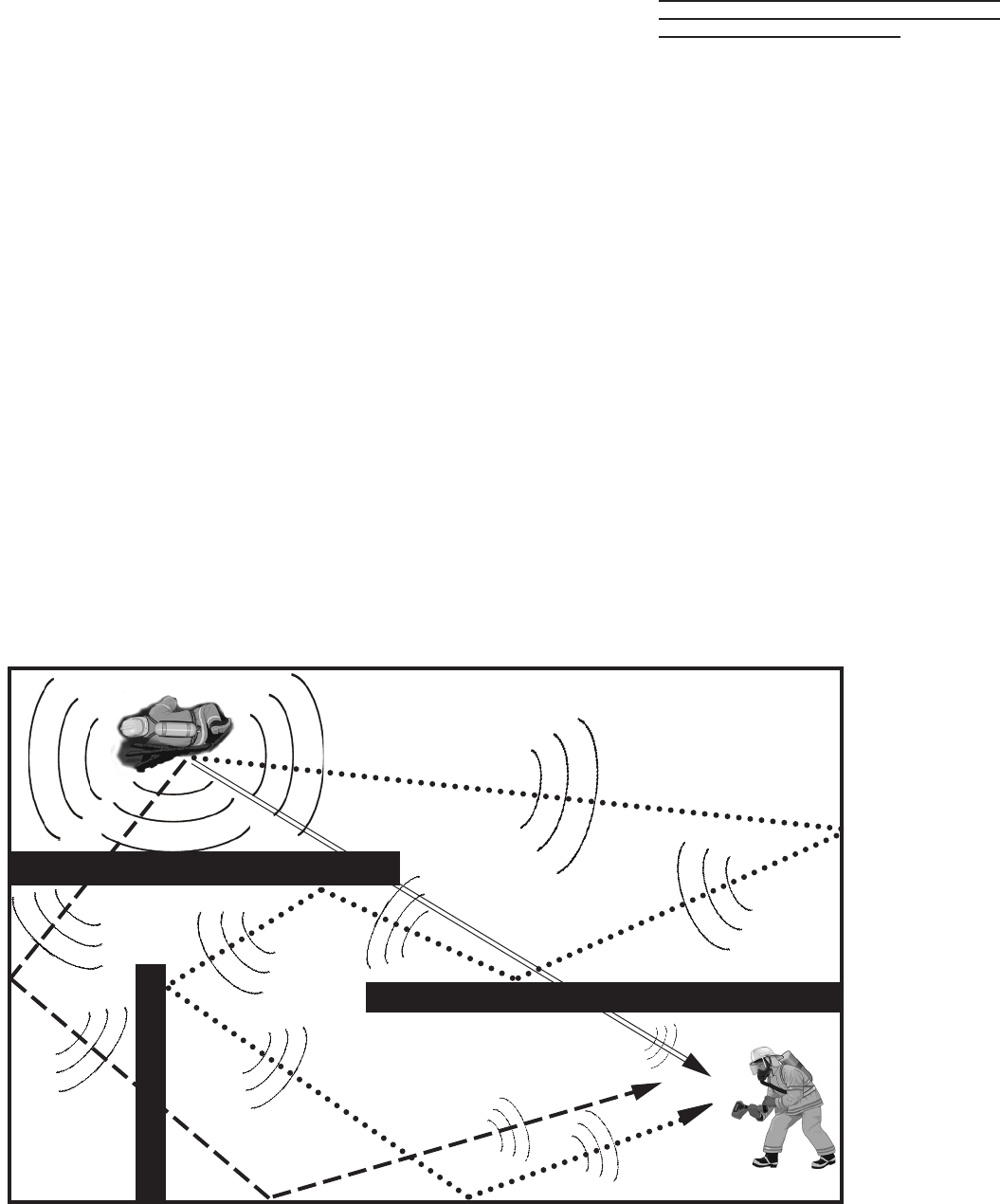
PRINCIPLES OF OPERATION
OF THE PAK-TRACKER LOCATOR SYSTEM
The SCOTT PAK-TRACKER locator system is an electronic system consisting of a
Hand Held Receiver and a Transmitter built into the SEMS II Sensor Module on the
SCBA backframe. The Transmitter is activated when the PASS is in Full Alarm. When
a Transmitter is activated, it sends out a radio signal in all directions that is received
by the Hand Held Receiver. Understanding how the radio signal from a Transmitter
behaves and how the Hand Held Receiver receives and displays the strength of
that signal are critical to understanding the operation of the SCOTT PAK-TRACKER
locator system.
WARNING
READ AND UNDERSTAND THIS ENTIRE MAN-
UAL AND THE PAK-TRACKER LOCATOR
SYSTEM MANUAL, P/N 595102-01. TRAINING IS
REQUIRED BEFORE USE OF THIS EQUIPMENT
IN A HAZARDOUS SITUATION. THE TRAINING
MUST INCLUDE AN UNDERSTANDING OF THE
LIMITATIONS OF THE EQUIPMENT AND HOW TO
INTERPRET LOCATING INFORMATION, ALONG
WITH EXTENSIVE PRACTICE WITH THE SYSTEM
IN A VARIETY OF ENVIRONMENTS. USE OF THIS
EQUIPMENT MUST BE A PART OF A COMPLETE
PERSONNEL ACCOUNTABILITY SYSTEM.
ALWAYS UPDATE TRAINING WITH EACH NEW
PIECE OF EQUIPMENT. USE OF A PAK-TRACKER
LOCATOR SYSTEM WITHOUT PROPER TRAIN-
ING MAY PLACE THE USERS AT HIGHER RISK
IN DANGEROUS SITUATIONS WHICH COULD
RESULT IN SERIOUS INJURY OR DEATH.
MULTIPLE SIGNAL PATHS ARE POSSIBLE
OPERATION AND USE OF
THE SCOTT PAK-TRACKER LOCATOR SYSTEM
Page 19 of 36
P/N 595289-01 Rev B 5/15
WARNING
CONTINUED TRAINING AND PRACTICE IN A
VARIETY OF SITUATIONS IS ESSENTIAL TO
DEVELOPING THE SKILLS TO PROPERLY IN-
TERPRET THE INFORMATION PROVIDED BY
THE PAK-TRACKER LOCATOR SYSTEM. USE
OF THIS EQUIPMENT WITHOUT TRAINING AND
PRACTICE MAY JEOPARDIZE ALL PERSONNEL
INVOLVED WHICH COULD LEAD TO SERIOUS
INJURY OR DEATH.
Successful operation of the PAK-TRACKER Locator system depends heavily on the
interpretation of the relative signal strength information displayed on the Hand Held
Receiver along with all other available information about the possible location of the
activated transmitter.
The Hand Held Receiver is very sensitive in responding to small differences in signal
strength. The relative strength of the Transmitter signal detected by the Hand Held
Receiver will vary depending on:
1. The distance from the Transmitter to the Hand Held Receiver,
2. The path the Transmitter signal has taken to get to the Hand Held Receiver,
3. The materials between the Transmitter and the Hand Held Receiver which may
have affected the signal from the Transmitter.
The user of the Hand Held Receiver must interpret the readings on the Hand Held
Receiver display along with other information, such as:
– training and knowledge in systematic search and rescue techniques,
– their sense of sight (watch where you are going),
– their sense of sound (listen for an activated PASS device),
– the deployment of the missing personnel,
– knowledge of the building layout and building materials,
Do not rely solely on the readings from the Hand Held Receiver to locate the activated
Transmitter.
Refer to the PAK-TRACKER Locator System User Instructions, SCOTT P/N 595102-01
for complete details on the use of the PAK-TRACKER Locator System.
When a SEMS II Control Console has been programmed with the user’s RFID Tag, the
PAK-TRACKER locator system will display the rst eight characters of the Employee ID
number as programmed on the RFID Tag. The rst eight (8) characters of the Employee
ID number on the RFID Tag must be unique to that individual. Use a badge number or
some other identier that is not shared by anyone else. Using a unique number in the
rst eight (8) characters will assure that searchers using the PAK-TRACKER locator
system will not see two signals with the same number displayed.
If the RFID Tag is not used, PAK-TRACKER locator system will display the default
eight digit ID number which appears on a label beside the cable connection on the
Sensor Module. This default number can be reprogrammed using the SCOTT Pak-
Link Computer Interface. Refer to the Pak-Link Computer Interface Installation and
Use Instructions, SCOTT P/N 595123-01, for complete details.
To return to the default ID number and remove the programmed RFID card number,
proceed as follows:
1. Verify that the air cylinder is closed and there is no residual air in the system.
2. Verify that the electronics have been inactive for at lease thirty (30) seconds.
3. Press and hold the YELLOW button on the Console for eight (8) seconds until
the red LEDS begin ashing alternately.
In addition, the unit will automatically return to the default ID number:
– if the battery cover is opened and/or the batteries are removed,
OR
– after twenty-four hours.
SCOTT recommends re-programming with the RFID card in accordance with your orga-
nization's procedures to assure that the user's unique ID number is in use at all times.
Page 20 of 36
P/N 595289-01 Rev B 5/15
REGULAR OPERATIONAL INSPECTION
Inspect and test the SCOTT SEMS II distress alarm, SEMS II Accountability System,
and the PAK-TRACKER Locator System along with the inspection and test of the
SCOTT SCBA respirator before each use. Refer to the PAK-TRACKER User Instruc-
tions, SCOTT P/N 595102-01, provided with the SCOTT PAK-TRACKER Hand Held
Receiver for complete details. Include the following inspection procedures with the
REGULAR OPERATIONAL INSPECTION procedures dened in your respirator in-
structions. If any malfunction of the respirator, the PAK-TRACKER Locator System,
or the SEMS II distress alarm or Accountability System is noted during the inspection,
remove the respirator from service and tag for repair by authorized personnel.
To test the PAK-TRACKER locator transmitter, you must have an operating SCOTT
PAK-TRACKER Hand Held Receiver.
WARNING
FOLLOW REGULAR OPERATIONAL INSPECTION
PROCEDURE EXACTLY. IF THE SEMS II
DISTRESS ALARM DOES NOT ACTUATE, OR IF
ANY OTHER FEATURE DOES NOT OPERATE AS
DESCRIBED OR IF ANY OTHER OPERATIONAL
MALFUNCTION IS NOTED, DO NOT USE THE
RESPIRATOR.
CAUTION
THE PERFORMANCE PROPERTIES OF THE
SEMS II DISTRESS ALARM CANNOT BE
PROPERLY TESTED IN THE FIELD.
WARNING
THE PROPER OPERATION OF THE LOCATOR
SYSTEM CANNOT BE CHECKED WITHOUT
CHECKING ALL COMPONENTS OF THE SYSTEM
TOGETHER. THE REGULAR OPERATIONAL
INSPECTION MUST INCLUDE THE HAND HELD
RECEIVER AND THE BASE STATION WORKING
WITH EACH OTHER TO CONFIRM PROPER
OPERATION. FAILURE TO PROPERLY INSPECT
THE COMPLETE SYSTEM MAY RESULT IN
FAILURE OF ONE COMPONENT WHICH COULD
LEAD TO SERIOUS INJURY OR DEATH.
NOTE
IN SEVERAL OF THE INSPECTION PROCEDURES DESCRIBED A FULL ALARM
WILL BE OBSERVED. THE FULL ALARM CONDITION INCLUDES AN AUDIBLE
TONE THAT CAN EXCEED 95 DBA AT 3 METERS (9.9 FT.). TO PREVENT POS-
SIBLE HEARING DAMAGE DURING TEST, IMMEDIATELY RESET THE ALARM
ON VERIFICATION THAT IT IS FUNCTIONING PROPERLY. WEAR HEARING
PROTECTION IF PROLONGED OR REPEATED EXPOSURE TO A FULL ALARM
CONDITION IS ANTICIPATED.
NOTE
IF THIS INSPECTION IS DONE IN DIRECT SUNLIGHT IT MAY BE HELPFUL TO
SHADE THE LENS ON THE CONTROL CONSOLE WITH YOUR HAND TO BE SURE
THE LIGHTS ARE FLASHING AS DESCRIBED.
1. While performing the visual inspection of the respirator, visually inspect all distress
alarm enclosures, lenses, and wire conduits for cracks, wear or other damage.
If any damage is found, remove the respirator from service and tag for repair by
qualied personnel.
2. Inspect the SCOTT PAK-TRACKER Hand Held Receiver for any cracks or signs
of damage. If any damage is found, remove the unit from service and tag for
repair by qualied personnel.
3. Turn on the SCOTT PAK-TRACKER Hand Held Receiver according to the operat-
ing instructions provided with the unit. Position the Hand Held Receiver near by.
4. Turn on the computer with the SCOTT SEMS II MESH GATEWAY Software with
the PCMCIA Communications Card or USB Gateway installed, according to this
instructions. Position the computer near by.
5. With the cylinder valve closed, press the manual alarm button, located on the
front of the distress alarm control console.
a) The manual alarm shall sound a loud almost continuous 3 tone chirp ac-
companied by ashing of the red signal light on the control console.
b) The PAK-TRACKER Hand Held Receiver will sound an alarm and display the
unique identication number of the SEMS II distress alarm. Use the SCROLL
button on the Hand Held Receiver to highlight the active ID number and
press the ENTER button on the Hand Held Receiver to select the displayed
ID number. Point the unit directly at and in close proximity to the respirator.
The signal strength displayed will be at its highest value.
c) Verify that the SEMS II functions are all operating properly and that PASS and
EVAC alarms and acknowledgements operate according to these instructions.
6. Reset the manual alarm by pressing twice on the reset button located on the side
of the control console (fully depress reset button, release and press again).
a) The unit will sound three chirps and the green light will ash.
b) The PAK-TRACKER Hand Held Receiver will reset to its non-alarm state.
7. Turn the SEMS II distress alarm OFF by pressing the reset button twice again.
The unit will sound a two tone chirp and the green light will go out.
8. Open the cylinder valve to pressurize the respirator system. The distress alarm
shall sound 3 quick chirps and the light on the control console shall begin ash-
ing green about once a second. The 3 chirps will sound approximately the same
time the VIBRALERT in the mask mounted regulator actuates briey. Make sure
the air ow is stopped by pressing the air saver/donning switch.
WARNING
IN SEVERAL OF THE INSPECTION PROCEDURES
DESCRIBED A FULL ALARM WILL BE OBSERVED.
THE FULL ALARM CONDITION INCLUDES AN
AUDIBLE TONE THAT CAN EXCEED 95 DBA AT
3 METERS (9.9 FT.). TO PREVENT POSSIBLE
HEARING DAMAGE DURING TEST, IMMEDIATELY
RESET THE ALARM ON VERIFICATION THAT IT
IS FUNCTIONING PROPERLY. WEAR HEARING
PROTECTION IF PROLONGED OR REPEATED
EXPOSURE TO A FULL ALARM CONDITION IS
ANTICIPATED.
Page 21 of 36
P/N 595289-01 Rev B 5/15
9. To check the pre-alarm, leave respirator motionless for twenty (20) seconds.
The green ashing light shall be replaced by a red ashing light. An ascending/
descending tone will sound increasing in volume. Leave the respirator motionless.
10. After the pre-alarm condition occurs, check the pre-alarm reset. Within twelve
(12) seconds of the pre-alarm, move the respirator to activate the motion sensor.
The SEMS II distress alarm shall reset to sensing mode. The red ashing light
shall be replaced by a green ashing light and the ascending/descending tone
shall stop.
Continue with regular operational inspection of respirator as directed by respirator
instructions or your approved respiratory protection plan procedure. During the
inspection the respirator must be moved or turned every thirty (30) seconds or
less to prevent the sounding of the full alarm.
After completion of all respirator checks and before turning off the cylinder
valve:
1. Check the manual reset of the pre-alarm. Leave the respirator motionless until
pre-alarm condition occurs. Within twelve (12) seconds press and single click
the reset button. Three (3) chirps shall sound, then release button. The distress
alarm shall reset to sensing mode and the alternating ashing red lights will be
replaced by a ashing green light.
2. To check the full alarm, leave the respirator motionless until the pre-alarm condi-
tion occurs. Do not reset.
a) The full alarm shall sound a loud almost continuous tone accompanied by
simultaneous ashing of the red signal lights on the control console.
b) The PAK-TRACKER Hand Held Receiver will sound an alarm and display the
Identication Number of the SEMS II distress alarm. The displayed number
will be either the Sensor ID number which appears on the label on the Sensor
Module or the ID number programmed using the SEMS II RFID Tag. Use the
SCROLL button on the Hand Held Receiver to highlight the active ID number
and press the ENTER button on the Hand Held Receiver to select the displayed
ID number. Point the unit directly at and in close proximity to the respirator.
The signal strength displayed will be at its highest value.
4. Reset the full alarm by pressing twice on the reset button located on the side of
the control console (fully depress reset button, release and press again).
a) The loud alarm shall stop. The unit will sound three chirps and the green light
will ash. The unit shall reset to sensing mode.
b) The PAK-TRACKER Hand Held Receiver will reset to its non-alarm state.
5. Finish all respirator checks involving air ow and turn off the cylinder valve. Use
the purge valve to release all residual air pressure in the system.
With the cylinder valve OFF:
1. Check the continuing operation of the distress alarm. The distress alarm shall
remain active with green light ashing. Do not move respirator, pre-alarm shall
occur with twenty (20) seconds. Move respirator slightly, pre-alarm shall reset,
green light shall start ashing again.
2. To turn the distress alarm off, press the reset button twice (press, release and
press again). If there is air pressure left in the system, the green ashing light will
continue to ash while a fteen second beep sequence is heard from the sen-
sor module as the residual air bleeds from the system. As soon as the air has
completely bled from system, the unit will sound a quick two tone chirp and the
PASS DEVICE distress alarm will be inactive. If there is no pressure in the system
when the RESET button is pressed twice, there will be no beep sequence. The
distress alarm is now in the “OFF” condition. If there is air pressure in the system,
the PASS DEVICE distress alarm will return to the active mode.
NOTE
IF THE LOW BATTERY INDICATION (ONE STEADY CHIRP EVERY TWO (2) SEC-
ONDS WITH NO FLASHING LIGHTS) OCCURS AT ANY TIME DURING REGULAR
OPERATIONAL INSPECTION, DO NOT USE THE RESPIRATOR. CHANGE THE BAT-
TERIES IN THE SENSOR MODULE IMMEDIATELY AND REPEAT THE REGULAR
OPERATIONAL TEST OR TAKE THE RESPIRATOR OUT OF SERVICE UNTIL THE
BATTERIES ARE CHANGED AND THE REGULAR OPERATIONAL TEST IS SUC-
CESSFULLY PERFORMED.
FORMED.
If any operational problems are found during the REGULAR OPERATIONAL INSPEC-
TION, do no use the respirator. Remove the respirator from service and tag for repair
by authorized personnel.
WARNING
FOLLOW REGULAR OPERATIONAL INSPECTION
PROCEDURE EXACTLY. IF THE SEMS II
DISTRESS ALARM DOES NOT ACTUATE, OR IF
ANY OTHER FEATURE DOES NOT OPERATE AS
DESCRIBED OR IF ANY OTHER OPERATIONAL
MALFUNCTION IS NOTED, DO NOT USE THE
RESPIRATOR.
WARNING
IF THE LOW BATTERY INDICATION (ONE
STEADY CHIRP EVERY TWO (2) SECONDS
WITH NO FLASHING LIGHTS) OCCURS AT
ANY TIME DURING REGULAR OPERATIONAL
INSPECTION, DO NOT USE THE RESPIRATOR.
CHANGE THE BATTERIES IN THE SENSOR
MODULE IMMEDIATELY AND REPEAT THE
REGULAR OPERATIONAL TEST OR TAKE THE
RESPIRATOR OUT OF SERVICE UNTIL THE
BATTERIES ARE CHANGED AND THE REGULAR
OPERATIONAL TEST IS SUCCESSFULLY
PERFORMED.
WARNING
FOLLOW REGULAR OPERATIONAL INSPECTION
PROCEDURE EXACTLY. IF THE SEMS II
DISTRESS ALARM DOES NOT ACTUATE, OR IF
ANY OTHER FEATURE DOES NOT OPERATE AS
DESCRIBED OR IF ANY OTHER OPERATIONAL
MALFUNCTION IS NOTED, DO NOT USE THE
RESPIRATOR.

Page 22 of 36
P/N 595289-01 Rev B 5/15
When performing the REGULAR OPERATIONAL INSPECTION verify that
the Sensor Module lights are operating as described below:
OPERATION OF SENSOR MODULE LIGHTS
NOTE
THE ORANGE LIGHT IS A COMBINATION OF THE RED, GREEN, AND BLUE
LIGHTS THAT APPEARS ORANGE FROM A DISTANCE. AT CLOSE RANGE THE
INDIVIDUAL LIGHTS MAY BE VISIBLE.
ACTION... SENSOR MODULE LIGHTS WILL…
Start up PASS (Open Cylinder) .................................................. Bright Light then Flash GREEN
Normal Operation ........................................................................ Flash GREEN
Respirator Low air (1/3 cylinder) ................................................. Flash ORANGE (alternately)
Low Battery while ON ................................................................. GREEN light stops ashing
Shut down .................................................................................. Lights OFF
Press RESET w/unit OFF (BATTERY TEST) ........................... Bright Light then:
Flash GREEN if Good/Flash RED if Low
Press MANUAL ALARM with unit OFF ..................................... Flash GREEN then Full Alarm Flash RED
Press RESET from manual alarm ............................................. Returns to Flash GREEN
PASS Pre-Alarm ........................................................................ Flash RED (alternately)
PASS Full alarm ......................................................................... Flash RED (simultaneously)
REGULAR OPERATIONAL INSPECTION CONTINUED...
Page 23 of 36
P/N 595289-01 Rev B 5/15
CLEANING, MAINTENANCE AND STORAGE
Cleaning, maintenance and storage of a respirator with a SEMS II distress alarm shall
be done as part of the normal respirator CLEANING AND STORAGE and REGULAR
OPERATIONAL INSPECTION as described in the OPERATING AND MAINTENANCE
INSTRUCTIONS supplied with each SCOTT respirator.
Refer to the PAK-TRACKER User Instructions, SCOTT P/N 595102-01, provided with
the SCOTT PAK-TRACKER Hand Held Receiver for complete details of cleaning and
storage of the Hand Held Receiver.
Store the respirator and attached distress alarm in accordance with the OPERATION
AND MAINTENANCE INSTRUCTIONS provided with the respirator. Do not store
respirators equipped with distress alarms in the proximity of radio antennas or radio
transmitter base units. Respirators equipped with SEMS II distress alarms must be
stored or transported at least two (2) feet away from radio antennas on re equipment.
Refer to the DETECTING AND AVOIDING RADIO FREQUENCY INTERFERENCE
section of this instruction for details.
Clean the exterior of the SEMS II distress alarm while cleaning the exterior of the
respirator by wiping with a damp sponge and thoroughly wiping dry. The Signal Light
lens on the front of the control console should be cleaned after every use to insure
maximum light intensity at all times. Do not use solvents for cleaning or attempt to
paint or apply decals to the exterior surfaces of the SEMS II distress alarm.
If during use, the respirator and/or SEMS II distress alarm is suspected of being
contaminated by a hazardous substance, the contaminant must be identied and
properly removed or the contaminated component(s) must be replaced before next
use. Dispose of the contaminant or the contaminated component(s) in accordance
with applicable regulatory requirements.
Except for the replacement of batteries, no attempt shall be made to do maintenance
or to make adjustments or repairs beyond the scope of this instruction manual without
proper training.
MARKING AND PAINTING
Do not mark, etch, paint, drill, or apply labels to any of the SEMS II ACCOUNTABILITY
SYSTEM components or housings in any way.
REPLACEMENT PARTS AND SERVICE
The SEMS II distress alarm is covered by a one year warranty.
Consult your Authorized SCOTT Representative, Distributor or Service Center as to
the availability of Service and Parts for the SEMS II distress alarm. Replacement Bat-
teries of the type designated are commercially available over the counter, from your
SCOTT Distributor, and from most Industrial Battery Distributors.
Except for the replacement of batteries, no attempt shall be made to do maintenance
or to make adjustments or repairs beyond the scope of this instruction manual without
proper training.
RETIREMENT CRITERIA AND CONSIDERATION
Retirement criteria and consideration shall be determined by SCOTT trained and
Certied Overhaul Technicians.
CLEANING, MAINTENANCE
AND STORAGE CONTINUED
ON NEXT PAGE...

Page 24 of 36
P/N 595289-01 Rev B 5/15
WARNING
READ AND UNDERSTAND THE COMPLETE INSTRUCTION MANUAL BEFORE USING A
RESPIRATOR WITH A SEMS II DISTRESS ALARM INSTALLED.
WHEN THE SEMS II
DISTRESS ALARM IS: IT INDICATES THAT:
Quiet. No lights or sound
Flashing the green light
Flashing the red light and sounding an
ascending/descending tone.
Flashing the red light and sounding a
loud continuous tone
Chirping once every two (2) seconds with
nolightashing
The SEMS II distress alarm is off or the
batteries are used up or removed.
The SEMS II distress alarm is on, in sens-
ing mode, and monitoring your motion.
You have not moved in the last twenty (20)
seconds, SEMS II distress alarm will go
into full alarm in twelve (12) seconds or
less if you do not move.
Full alarm: You have not moved in the last
thirty (30) seconds or more or you pushed
the manual alarm button.
The batteries are low. You must put in new
batteries before using the SEMS II distress
alarm again (it will work in low battery
conditionlongenoughtoletyounishthe
cylinder of air you are on).
QUICK REFERENCE GUIDE TO USE:
WHEN YOU WANT TO: YOU DO: THE SEMS II DISTRESS ALARM
DOES:
Turn it on.
Re-set pre-alarm
Re-set full alarm
Turnitoff(nishedwithuse)
Turn on the manual alarm.
Open cylinder valve (cylinder
must have air in it).
Move so that the respirator
moves.
3 quick audible chirps, green
ashinglightoncontrolconsole.
Redashinglightchangesto
green, ascending/descending
tone stops.
Loud 3 tone chirp stops, 3 quick
chirps,thenredashinglight
changestogreenashinglight.
Theashinglightgoesoutand
afteen(15)secondbeepse-
quence occurs as the residual air
bleeds off. Unit will sound a two
tone chirp at turn off.
Goes into full alarm, loud 3 tone
chirps from sensor module and
bright red ashinglightfromcon-
trol console.
Press re-set button on control
console twice (push, release,
push again).
Close respirator cylinder valve,
open regulator purge valve
letting out all the trapped air,
close regulator purge valve,
press re-set button twice.
Press alarm button on control
console (works whether the
SEMS II distress alarm is on or
off).
CLEANING, MAINTENANCE AND STORAGE CONTINUED...
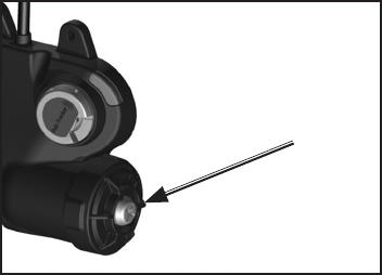
Page 25 of 36
P/N 595289-01 Rev B 5/15
CAUTION
RESPIRATOR SYSTEM MUST NOT BE
PRESSURIZED WHEN BATTERIES ARE BEING
INSTALLED. DAMAGE TO THE ELECTRONIC
COMPONENTS MAY RESULT IF BATTERIES
ARE INSTALLED WITH SYSTEM PRESSURIZED.
SCOTT respirators equipped with the PAK-ALERT distress alarm require six (6) “AA”
cell batteries for operation. The six (6) batteries power the Heads-Up Display, the
PASS device, and the PAK-TRACKER Transmitter.
NOTE
THE UNIT WILL RETURN TO THE DEFAULT ID NUMBER IF THE BATTERY COVER
IS OPENED AND/OR THE BATTERIES ARE REMOVED. SCOTT RECOMMENDS
RE-PROGRAMMING WITH THE RFID CARD IN ACCORDANCE WITH YOUR
ORGANIZATION'S PROCEDURES TO ASSURE THAT THE USER'S UNIQUE ID
NUMBER IS IN USE AT ALL TIMES.
The batteries should be replaced only by a trained maintenance technician in a clean
area known to be nonammable.
Replace batteries as follows:
1. Close respirator cylinder valve, open regulator purge valve letting out all the
trapped air, close regulator purge valve, press the reset button twice. If there is
air pressure left in the system, the green ashing light will continue to ash while
a fteen second beep sequence is heard from the Sensor Module as the residual
air bleeds from the system. As soon as the air has completely bled from system,
the unit will sound a quick two tone chirp and the PASS DEVICE distress alarm
will be inactive. If there is no pressure in the system when the RESET button
is pressed twice, there will be no beep sequence. If there is air pressure in the
system, the PASS DEVICE distress alarm will return to the active mode.
NOTE
ALWAYS BE SURE THAT CYLINDER VALVE IS OFF AND THE PASS DEVICE IS
COMPLETELY INACTIVE BEFORE CHANGING BATTERIES. NEVER REMOVE OR
REPLACE BATTERIES WITH SYSTEM PRESSURIZED.
2. When replacing batteries on respirators, remove the cylinder and place the res-
pirator in a clean, non-hazardous area.
3. Use a Phillips driver to remove the Battery Housing Cover. Carefully remove the
cover and set aside.
4. Remove used batteries from battery compartment by sliding them out of the bat-
tery compartment.
5. Install six (6) fresh new “AA” batteries of the same type. Always replace all bat-
teries at the same time.
The battery holder is marked with the style and orientation of the batteries required.
Use six (6) each of one of the following 1.5 volt AA batteries:
– Duracell2 Alkaline MN1500
– Duracell Alkaline MX1500
– Duracell Alkaline PC1500
– Duracell Quantum MV1500
– Eveready Energizer3 Alkaline EN91
– Eveready Energizer Alkaline E91.
Do not mix batteries. Verify correct orientation of batteries as shown on label
inside the battery holder.
WARNING
THE SEMS II DISTRESS ALARM IS INTENDED TO
ASSIST IN LOCATING A PERSON WHO MAY BE IN
A LIFE THREATENING SITUATION. FAILURE TO
FOLLOW THE INSTRUCTIONS FOR OPENING,
CHANGING THE BATTERIES AND RE-CLOSING
THE BATTERY COMPARTMENT MAY RESULT
IN DAMAGE WHICH COULD CAUSE FAILURE
OF THE PASS DURING A LIFE THREATENING
EMERGENCY OR COULD CAUSE A FIRE OR
EXPLOSION IN A FLAMMABLE OR EXPLOSIVE
ATMOSPHERE POSSIBLY RESULTING IN INJURY
OR DEATH.
WARNING
BATTERIES MUST ONLY BE CHANGED IN
AN AREA KNOWN TO BE NONFLAMMABLE.
CHANGING THE BATTERIES IN A FLAMMABLE
ATMOSPHERE MAY CAUSE AN IGNITION WHICH
COULD RESULT IN SERIOUS INJURY OR DEATH.
BATTERY REPLACEMENT
2 Duracell is a registered trademark of The Procter & Gamble Company, Cincinnati, OH
3 Energizer is a registered trademark of Eveready Battery Company, Inc., St Louis, MO.
WARNING
TO REDUCE THE RISK OF EXPLOSION
USE BATTERIES ONLY FROM THE LIST
PROVIDED, DO NOT MIX OLD BATTERIES
WITH UNUSED BATTERIES, AND DO NOT MIX
BATTERIES FROM DIFFERENT MANUFAC-
TURERS. UNAUTHORIZED SUBSTITUTION OF
COMPONENTS MAY IMPAIR INTRINSIC SAFETY
AND CAUSE AN EXPLOSION WHICH COULD
LEAD TO SERIOUS INJURY OR DEATH.
USE SCREWDRIVER
TO LOOSEN SCREW
AND REMOVE COVER
WARNING
ALWAYS INSTALL THE BATTERIES IN THE
ORIENTATION SHOWN ON THE LABEL. FAILURE
TO PROPERLY INSTALL THE BATTERIES
WILL RESULT IN EITHER REDUCED OR NO
OPERATION OF THE EQUIPMENT WHICH
COULD LEAD TO FAILURE OF THE EQUIPMENT
AND SERIOUS INJURY OR DEATH OF THE
RESPIRATOR USER.
BATTERY REPLACEMENT
CONTINUED ON NEXT PAGE...
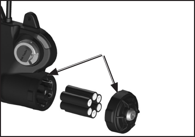
Page 26 of 36
P/N 595289-01 Rev B 5/15
CHECK YOUR WORK!
BEFORE ASSEMBLY OF BATTERY COVER,
CHECK TO SEE ALL BATTERIES ARE FRESH,
NEW BATTERIES OF THE TYPE INDICATED
ABOVE AND THAT THEY HAVE BEEN INSTALLED
PROPERLY.
BE SURE SEALING
SURFACES ARE CLEAN
BEFORE REASSEMBLY
6. The battery cover must be installed so that it is water tight after replacement.
Clean the sealing rib around battery compartment and sealing face of the cover
by wiping with a clean damp cloth to remove any dirt or foreign matter which might
prevent a proper seal. Check cover gasket for tears or cuts. If damage is found,
remove respirator from service and tag for repair by authorized personnel.
7. To install battery cover, align the three grooves on the cover with the three tabs
on the battery compartment and tighten the cover screw.
8. To test the batteries, verify that the PAK-ALERT distress alarm is in the off condi-
tion (cylinder valve closed with no ashing green LED on the control console).
a) Press and hold the reset button on the console. A GREEN light on the console
indicates sufcient battery power and that the batteries are properly installed.
b) If the unit displays the LOW BATTERY condition or no light at all, verify that
the batteries are properly installed. If the batteries were properly installed,
remove the batteries and replace with a new set of six (6) batteries.
c) If another set of properly installed batteries will still not produce a GREEN
light on the battery test, remove the unit from service and mark for repair by
authorized personnel.
AFTER REPLACEMENT OF BATTERIES, PERFORM A REGULAR OPERATIONAL
INSPECTION BEFORE RETURNING RESPIRATOR TO SERVICE.
BATTERY REPLACEMENT CONTINUED...
CAUTION
IMPROPER BATTERY COVER INSTALLATION
CAN CAUSE BATTERIES TO OVERHEAT AND
MAY CAUSE DAMAGE TO THE PRODUCT.
ALWAYS MAKE SURE THAT THE ALIGNMENT
GROOVES ON THE BATTERY COVER ARE
ALIGNED WITH THE TABS ON THE BATTERY
COMPARTMENT DURING INSTALLATION OF
THE COVER.
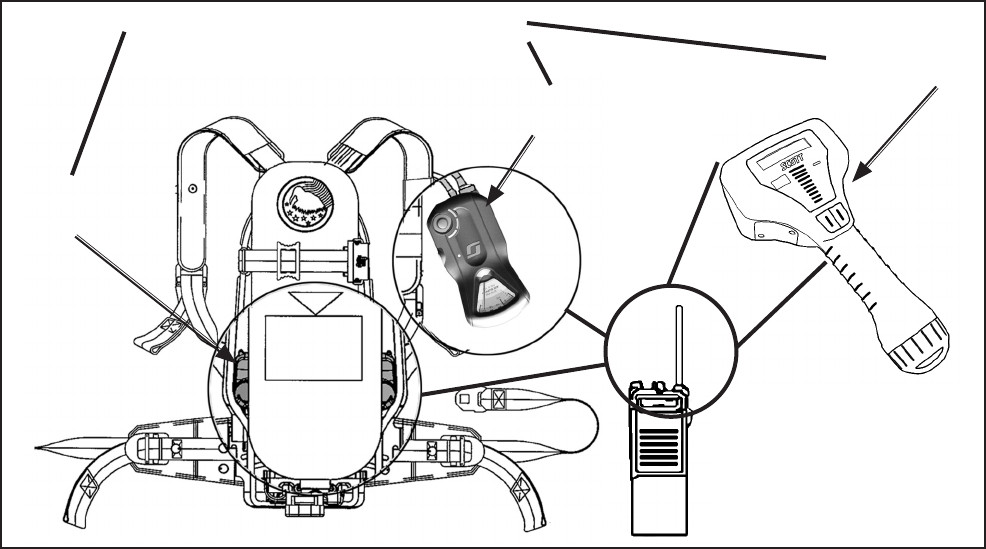
Page 27 of 36
P/N 595289-01 Rev B 5/15
WARNING
KEEP THE ANTENNAS OF HAND-HELD RADIOS
AT LEAST SIX (6) INCHES AWAY FROM THE
CONTROL CONSOLE AND THE SENSOR
MODULE OF THE SEMS II DISTRESS ALARM
WHEN TRANSMITTING. CLOSE PROXIMITY OF
RADIO EQUIPMENT TO THE SEMS II DISTRESS
ALARM DURING RADIO TRANSMISSION MAY
CAUSE THE UNIT TO MALFUNCTION. FAILURE
TO RECOGNIZE A MALFUNCTION OF THE
SEMS II DISTRESS ALARM AND TAKE THE
PROPER CORRECTIVE ACTION MAY RESULT A
NONWORKING DISTRESS ALARM WHICH WILL
NOT SOUND IF THE USER STOPS MOVING AND
LEAD TO SERIOUS INJURY OR DEATH.
WARNING
BE AWARE OF THE POTENTIAL EFFECT
OF RADIO TRANSMISSIONS FROM BASE
STATION OR TRUCK MOUNT RADIOS WHEN
USING A RESPIRATOR WITH THE SEMS II
DISTRESS ALARM. CLOSE PROXIMITY OF
RADIO EQUIPMENT TO THE SEMS II DISTRESS
ALARM DURING RADIO TRANSMISSION MAY
CAUSE THE UNIT TO MALFUNCTION. FAILURE
TO RECOGNIZE A MALFUNCTION OF THE
SEMS II DISTRESS ALARM AND TAKE THE
PROPER CORRECTIVE ACTION MAY RESULT A
NONWORKING DISTRESS ALARM WHICH WILL
NOT SOUND IF THE USER STOPS MOVING AND
LEAD TO SERIOUS INJURY OR DEATH.
DETECTING AND AVOIDING
RADIO FREQUENCY INTERFERENCE
When any electronic device is adversely affected by radio waves, Radio Frequency
Interference (RFI) is said to have occurred. All electronic devices like the SEMS II
distress alarm may be subject to the effects of RFI. Radio transmissions from the
antennas of radios including those used by re ghters, police and other public safety
related personnel may produce RFI in the SEMS II distress alarm. RFI may occur while
the radio is transmitting if the respirator equipped with the SEMS II distress alarm is
in close proximity to a base station or high-powered vehicle mounted radio, or if the
antenna of a personal portable hand held radio is touching or within six (6) inches of
the Control Console or Sensor Module of the SEMS II distress alarm.
Be aware of the symptoms of RFI. A SEMS II distress alarm affected by RFI may
temporarily give false indications such as the sudden sounding of the loud continuous
three-tone chirp of the full alarm. In some instances the lights on the control console
may ash without sounding the alarm. In rare circumstances, an alarm which was
sounding may stop.
If the SEMS II distress alarm exhibits any of the symptoms of RFI, identify the source
of the RFI and do the following:
– If the symptoms of RFI occur when standing near a base station transmitting
antenna or a truck mounted radio antenna, move away from the antenna until
the symptoms stop.
– If the symptoms of RFI occur while transmitting on a hand-held radio, move the
radio away from the SEMS II distress alarm .
CHECK THE CONTROL CONSOLE AND BE CERTAIN THE GREEN LIGHT IS
FLASHING NORMALLY WHEN THE INTERFERENCE STOPS, REGARDLESS OF
THE SOURCE.
In normal usage with the air cylinder open, the SEMS II distress alarm will typically
resume normal operation after experiencing RFI.
If the SEMS II distress alarm is affected by RFI when the respirator air supply is turned
off or the cylinder is empty, the distress alarm could be turned off during use. If this
occurs, depress the RED Manual Alarm Button to activate the alarm.
IF THE SYMPTOMS OF RFI OCCUR, THE RESPIRATOR USER MUST CHECK THE
SEMS II DISTRESS ALARM TO VERIFY THAT IT IS FUNCTIONING PROPERLY. IF
THE GREEN LIGHT ON THE CONTROL CONSOLE DOES NOT RESUME FLASH-
ING IN THE NORMAL MANNER AFTER EXPERIENCING THE SYMPTOMS OF RFI,
OR IF THE UNIT CONTINUES TO MALFUNCTION IN ANY OTHER WAY, PROCEED
TO A SAFE AREA, REMOVE THE RESPIRATOR FROM SERVICE AND TAG FOR
REPAIR BY AUTHORIZED PERSONNEL.
HAND HELD
RECEIVER
SENSOR
MODULE
CONTROL
CONSOLE
KEEP RADIO ANTENNAS AT LEAST
SIX (6) INCHES FROM THESE AREAS
RFI WARNING AREAS
Page 28 of 36
P/N 595289-01 Rev B 5/15
Minimize or eliminate the effects of RFI by protecting the SEMS II distress alarm with
the following steps:
– Maintain a safe distance from a base station transmitting antenna or a truck
mounted radio antenna.
– Keep the antennas of hand held radios at least six (6) inches away from the CON-
TROL CONSOLE or the SENSOR MODULE.
RFI AND THE PAK-TRACKER HAND HELD RECEIVER
If the Hand Held Receiver experiences RFI, it may be necessary to remove the Hand
Held Receiver from service. In a known safe, non-hazardous area, remove and reinstall
the batteries to reset the unit (see the BATTERY REPLACEMENT section of the PAK-
TRACKER Locator System User Instructions, SCOTT P/N 595102-01). Then inspect
and return the Hand Held Receiver to service.
Page 29 of 36
P/N 595289-01 Rev B 5/15
CLASS B DIGITAL DEVICE
Note: This equipment has been tested and found to comply with the limits for a Class
B digital device, pursuant to Part 15 of the FCC Rules. These limits are designed to
provide reasonable protection against harmful interference in a residential installation.
This equipment generates, uses and can radiate radio frequency energy and, if not
installed and used in accordance with the instructions, may cause harmful interference
to radio communications. However, there is no guarantee that interference will not
occur in a particular installation. If this equipment does cause harmful interference to
radio or television reception, which can be determined by turning the equipment off
and on, the user is encouraged to try to correct the interference by one or more of
the following measures:
– Reorient or relocate the receiving antenna
– Increase the separation between the equipment and receiver.
– Connect the equipment into an outlet on a circuit different from that to which the
receiver is connected.
– Consult the dealer or an experienced radio/TV technician for help.
FCC COMPLIANCE
FCC Compliance Statement (Part 15.19)
This device complies with Part 15 of the FCC Rules. Operation is subject to the
following two conditions:
1. This device may not cause harmful interference, and
2. This device must accept any interference received, Including interference that
may cause undesired operation.
FCC Warning (Part 15.21)
Changes or modications not expressly approved by the party responsible for compli-
ance could void the user’s authority to operate the equipment.
This portable transmitter with its antenna complies with FCC/IC RF exposure limits for
general population / uncontrolled exposure.
The X3 SEMS II Control Console Transmitter has been assigned
FCC ID:T5E201122 / The X3 SEMS II with BLUETOOTH Control Console Trans-
mitter has been assigned FCC ID: T5E201122A
SAFETY LISTINGS
CAUTION
DO NOT USE A FIBERGLASS WRAPPED
ONE HOUR CYLINDER ON A MODEL 4.5
AIR-PAK EQUIPPED WITH A PAK-ALERT DIS-
TRESS ALARM AS THE WEIGHT WILL EXCEED
THE 35 LBS APPROVAL LIMIT FOR SCBA’S
ESTABLISHED BY NIOSH.
INDUSTRY CANADA COMPLIANCE
Industry Canada Statement
The term “IC” before the certication / registration number only signies that the In-
dustry Canada technical specications were met.
Section 14 of RSS-210
The installer of this radio equipment must ensure that the antenna is located or pointed
such that it does not emit RF eld in excess of Health Canada limits for the general
population. Consult Safety Code 6, obtainable from Health Canada’s web site: www.
hc-sc.gc.ca/rpb.
This Device complies with Industry Canada License-exempt RSS standard(s). Opera-
tion is subject to the following two conditions:
1. this device may not cause interference, and
2. this device must accept any interference, including interference that
may cause undesired operation of the device.
IC ID: 6453A-201122 / 6453A-201122A
LA DÉCLARATION DE CANADA D'INDUSTRIE
L' « IC » de terme avant que la certication/le nombre d'enregistrement signie seule-
ment que le Canada d'Industrie spécications techniques ont été rencontrées.
Sectionner 14 de RSS-210
Le programme d'installation de cet équipement de radio doit garantir que l'antenne
est localisée ou tel est indiqué qu'il n'émet pas le champ de RF dépassant les limites
de Canada de Santé pour la population générale. Consulter le Code de Sécurité 6,
procurable du site Web de Canada de Santé : www.hc-sc.gc.ca/rpb.
Cet appareil est conforme aux normes Industry Canada exemptes de licence RSS
standard(s). L'opération est assujetti au suivre deux conditions :
1) cet appareil ne peut pas causer l'intervention, et
2) cet appareil doit accepter de l'intervention, y compris l'intervention
qui peut causer l'opération non désirée de l'appareil.
IC ID: 6453A-201122 / 6453A-201122A

Page 30 of 36
P/N 595289-01 Rev B 5/15
INTRINSICALLY SAFE LISTING
The SEMS II distress alarm with Integrated Locator transmitter, Model Number
200451-SERIES, when installed on a SCOTT respirator, is listed as intrinsically safe
per ANSI/UL Std. UL-913 in Class I, II, Division 1, Groups C, D, E, F, and G hazardous
locations by SGS U. S. TESTING COMPANY, Inc. Only when powered by the batteries
listed in this instruction or indicated on the label on the sensor module.
To maintain Intrinsic Safety Listing, inspect the respirator with SEMS II distress alarm
regularly per the Regular Operational Inspection procedures in this instruction. Sub-
stitution of Components May Impair Intrinsic Safety. To reduce the risk of ignition of
a ammable atmosphere, batteries must only be changed in an area known to be
nonammable. To reduce the risk of explosion, use only the approved batteries, do not
mix old batteries with unused batteries, or mix batteries from different manufacturers.
HAND HELD RECEIVER NON-INCENDIVE LISTING
The SCOTT PAK-TRACKER LOCATOR SYSTEM Hand Held Receiver P/N 200397-
02 is listed by SGS U. S. TESTING COMPANY, Inc. as Non-Incendive per ANSI/UL
Std. UL-1604 for use in Class I Division 2 Groups A, B, C, and D hazardous locations.
Temperature Code T4 (-25° C to 85° C). To maintain the Non-Incendive Listing, the
equipment must be inspected regularly per the following Regular Operational Inspec-
tion procedures. Do not tamper with or substitute components in any manner. Use
only SCOTT Battery Pack P/N 200402-02. Open the battery compartment only in an
area known to be free of ammable or explosive hazards.
WARNING – Substitution of Components May Impair the Non-Incendive Listing. To
reduce the risk of ignition of a ammable atmosphere, battery must only be changed in an
area known to be nonammable. Do not substitute any other battery or power source.
WARNING
IF THE SEMS II DISTRESS ALARM IS USED
IN AN AREA OF EXPLOSIVE OR FLAMMABLE
HAZARDS, FAILURE TO REGULARLY INSPECT
AS INSTRUCTED, FAILURE TO CORRECT
DAMAGE BEFORE USE, OR THE INSTALLATION
OF INCORRECT BATTERIES MAY LEAD TO A
FIRE OR EXPLOSION WHICH MAY RESULT IN
PERSONAL INJURY OR DEATH.
WARNING
FAILURE TO REGULARLY INSPECT THE HAND
HELD RECEIVER AS DESCRIBED IN THIS IN-
STRUCTION OR FAILURE TO CORRECT ANY
DAMAGE FOUND, MAY IMPAIR THE SAFETY
OF THE EQUIPMENT. THE INSTALLATION OF
INCORRECT BATTERY OR SUBSTITUTION
OF ANY OTHER COMPONENTS MAY IMPAIR
THE SAFETY OF THE EQUIPMENT. IF THE
EQUIPMENT IS USED IN AN EXPLOSIVE OR
FLAMMABLE ATMOSPHERE, IMPAIRING THE
SAFETY OF THE UNIT MAY LEAD TO A FIRE
OR AN EXPLOSION WHICH COULD RESULT IN
SERIOUS INJURY OR DEATH.
WARNING
REPLACE HAND HELD RECEIVER BATTERY
PACK ONLY WITH SCOTT BATTERY PACK,
PART NO. 200402-02. DO NOT REMOVE, RE-
CHARGE, OR REPLACE BATTERY PACK WHILE
THE DEVICE IS IN A HAZARDOUS LOCATION.
REMOVING, RE-CHARGING, OR REPLACING
THE BATTERY PACK WHILE THE DEVICE IS IN
A HAZARDOUS LOCATION MAY LEAD TO A FIRE
OR AN EXPLOSION WHICH COULD RESULT IN
SERIOUS INJURY OR DEATH.
WARNING
RADIO FREQUENCY INTERFERENCE (RFI)
MAY CAUSE A MALFUNCTION OF THE SEMS
II PERSONAL DISTRESS ALARM. USERS OF
RESPIRATORS EQUIPPED WITH THE SEMS
II PERSONAL DISTRESS ALARM MUST BE
AWARE OF THE PROPER OPERATION OF THE
DISTRESS ALARM. FAILURE TO RECOGNIZE
A MALFUNCTION OF THE EQUIPMENT AND
TAKE PROPER CORRECTIVE ACTION MAY
RESULT FAILURE OF THE SEMS II PERSONAL
DISTRESS ALARM AND LEAD TO SERIOUS IN-
JURY OR DEATH.
RADIO FREQUENCY INTERFERENCE (RFI)
When any electronic device is adversely affected by radio waves, Radio Frequency
Interference (RFI) is said to have occurred. All electronic devices like the SEMS II
distress alarm may be subject to the effects of RFI, most of which are temporary in
nature. Users of the SCOTT SCBA with the integrated SEMS II distress alarm must
be familiar with the normal operation of the distress alarm and must also be familiar
with how to identify and avoid the effects of RFI (see DETECTING AND AVOIDING
RADIO FREQUENCY INTERFERENCE on page 6). If RFI occurs to the SEMS II
distress alarm, it may be caused by transmissions from hand-held or personal radios
where the radio antenna is touching or very close to (less than 6 inches from) com-
ponents of the SEMS II distress alarm. It may also be caused by transmissions from
base stations or high-powered vehicle mounted radios or any other powerful source
of electromagnetic radiation.
WARNING
SUBSTITUTION OF COMPONENTS MAY IMPAIR
INTRINSIC SAFETY. TO REDUCE THE RISK OF
IGNITION OF A FLAMMABLE ATMOSPHERE,
BATTERIES MUST ONLY BE CHANGED IN AN
AREA KNOWN TO BE NONFLAMMABLE. TO
REDUCE THE RISK OF EXPLOSION, DO NOT
MIX OLD BATTERIES WITH UNUSED BATTER-
IES, OR MIX BATTERIES FROM DIFFERENT
MANUFACTURERS.
Page 31 of 36
P/N 595289-01 Rev B 5/15
SEMS II DISTRESS ALARM
PERFORMANCE SPECIFICATIONS
Sound Levels:
Pre-Alarm... ......................... 80 to 105 dBA incrementally at left ear
Full-Alarm ............................ 95 to 100 dBA @ 9.9 Ft. (3m)
Frequency Range ............... 1.5 KHz to 4 KHz
Battery Life (fresh batteries)
Alkaline Batteries:
Automatic (green ashing light, no sound) ..............Approx. 20 hours
Full Alarm (red ashing light, 95 dBA sound)....... .Approx. 8 hours
Compliance
The SCOTT SEMS II distress alarm is a NIOSH approved accessory for
use on only the following SCOTT SCBA respirators:
(NIOSH approval numbers have been included for identication):
SCOTT AIR-PAK X3 SNAP-CHANGE SCBA
SCOTT 2.2 AIR-PAK X3 (30 min.) TC-13F-0712CBRN
SCOTT 4.5 AIR-PAK X3 (30 min.) TC-13F-0714CBRN
SCOTT 4.5 AIR-PAK X3 (45 min.) TC-13F-0716CBRN
SCOTT 4.5 AIR-PAK X3 (60 min.) TC-13F-0718CBRN
SCOTT 5.5 AIR-PAK (30 min.) TC-13F-0720CBRN
SCOTT 5.5 AIR-PAK (45 min.) TC-13F-0722CBRN
SCOTT 5.5 AIR-PAK (60 min.) TC-13F-0724CBRN
SCOTT 5.5 AIR-PAK (75 min.) TC-13F-0726CBRN
PERSONAL COMPUTER
The personal computer Base Station environmental operating parameters are totally
dependant on the limitations of the personal computer used with the SCOTT SEMS
II Accountability System. Do not use the personal computer Base Station in environ-
ments for which it is not designed. Handle the personal computer according to the
instructions provided with the personal computer.
EXPORT AND IMPORT
The international transport of the SCOTT SEMS II Accountability System and portions
thereof is regulated under United States export regulations and may be regulated by
the import regulations of other countries.
If you have any questions or concerns regarding these regulations, contact SCOTT at
1-800-247-7257 (or 704-291-8300 outside the continental United States).
SCOTT AIR-PAK X3 CGA SCBA
SCOTT 2.2 AIR-PAK X3 (30 min.) TC-13F-0711CBRN
SCOTT 4.5 AIR-PAK X3 (30 min.) TC-13F-0713CBRN
SCOTT 4.5 AIR-PAK X3 (45 min.) TC-13F-0715CBRN
SCOTT 4.5 AIR-PAK X3 (60 min.) TC-13F-0717CBRN
SCOTT 5.5 AIR-PAK (30 min.) TC-13F-0719CBRN
SCOTT 5.5 AIR-PAK (45 min.) TC-13F-0721CBRN
SCOTT 5.5 AIR-PAK (60 min.) TC-13F-0723CBRN
SCOTT 5.5 AIR-PAK (75 min.) TC-13F-0725CBRN
NOTE
DO NOT USE A FIBERGLASS WRAPPED ONE HOUR CYLINDER ON A
MODEL 4.5 AIR PAK EQUIPPED WITH A SEMS II DISTRESS ALARM AS
THE WEIGHT WILL EXCEED THE 35 LBS APPROVAL LIMIT FOR SCBA’s
ESTABLISHED BY NIOSH.
Page 32 of 36
P/N 595289-01 Rev B 5/15
END USER LICENSE AGREEMENT
IMPORTANT-READ CAREFULLY: THIS IS A LEGAL AGREEMENT BETWEEN YOU,
A SINGLE ENTITY (AS DEFINED IN SECTION 11 BELOW) (“YOU[R]”) AND SCOTT
TECHNOLOGIES, INC. d/b/a SCOTT HEALTH AND SAFETY, 4320 GOLDMINE
ROAD, MONROE, NC 28110 (“SCOTT”) PERTAINING TO THE SOFTWARE YOU
ARE ABOUT TO INSTALL, COPY, ACCESS OR OTHERWISE USE (SINGULARLY
AND COLLECTIVELY, THE “SOFTWARE”). SCOTT LICENSES THE SOFTWARE TO
YOU ONLY UPON THE EXPRESS CONDITION THAT YOU ACCEPT ALL OF THE
TERMS AND CONDITIONS CONTAINED IN THIS LICENSE AGREEMENT (THE
“AGREEMENT”). YOU SHOULD CAREFULLY READ THE FOLLOWING TERMS AND
CONDITIONS BEFORE ACCESSING THE SOFTWARE. BY OPENING THE SEALED
PACKAGE, INSTALLING, COPYING, ACCESSING OR OTHERWISE USING THE
SOFTWARE, YOU ACCEPT THESE TERMS AND CONDITIONS AND UNDERSTAND
THAT THEY WILL BE LEGALLY BINDING ON YOU. IF YOU DO NOT AGREE TO THE
TERMS, THEN SCOTT IS UNWILLING TO LICENSE THE SOFTWARE TO YOU. IF
YOU DO NOT AGREE WITH THEM, OR DO NOT WANT THEM BINDING ON YOU,
YOU MUST NOT INSTALL, COPY, ACCESS OR OTHERWISE USE THE SOFTWARE
AND YOU MAY RETURN THE SOFTWARE FOR A FULL REFUND (LESS ANY SHIP-
PING FEES) WITHIN THIRTY (30) DAYS OF YOUR LICENSE PURCHASE DATE.
IMPORTANT WARNING: IT IS CRITICAL FOR YOU TO REGULARLY BACK UP
YOUR DATA. DATA BACK UP IS SOLELY YOUR RESPONSIBILITY. IN NO EVENT
SHALL SCOTT BE LIABLE FOR ANY LOSS OF DATA.
1. Grant of License. The Software is protected by copyright laws and international
copyright treaties, as well as other intellectual property laws and treaties. The
Software is licensed, not sold, as follows: SCOTT hereby grants and you accept
a non-exclusive, non-transferable license, subject to each provision of this Agree-
ment, including, but not limited to, Sections 2 and 3 herein: to install and use the
Software on only one (1) computer at one (1) location at any one (1) time. All
rights not expressly granted to you are hereby reserved by SCOTT.
Upgrades: If the Software is an upgrade (“New Version”) to a version previ-
ously licensed to you (“Previous Version”), you must destroy all copies of the
Previous Version. SCOTT reserves the right to require you to show satisfactory
proof that the Previous Version was destroyed. If SCOTT provides you additional
materials that supplement or extend the Software, those additional materials shall
be subject to this Agreement’s terms and conditions unless SCOTT otherwise
agrees in writing. Notwithstanding the foregoing, you may retain one (1) back-up
copy of the Previous Version and may use it solely: (i) to install the New Version
hereby licensed and (ii) for archival (backup) purposes to reinstall the New Ver-
sion hereby licensed if the initial installation fails. Under no circumstances may
you otherwise operate the Previous Version and your license rights to each such
Previous Version are terminated upon your rst successful installation of the New
Version.
2. Title and Copyright. It is hereby understood and agreed that as between SCOTT
and you, SCOTT is the owner of all rights, title and interest, including the copy-
right, to the Software recorded on the media on which the Software is furnished
and all subsequent copies thereof, regardless of the media or form in which the
Software or copies thereof may exist. Except as expressly provided herein, you
do not acquire any rights to the Software through the purchase of licenses to the
Software.
3. Limitations On Use. The License granted to You shall not extend to any third
party. Except as specically permitted pursuant to this Agreement, You shall not:
(i) copy (except as permitted by applicable law or as provided in this Agreement),
sell, modify, translate, transfer, reverse engineer, decompile or disassemble the
Software, provided, however, that if You require information necessary to create an
independent program which is interoperable with the Software, upon written noti-
cation of such requirement SCOTT will make the necessary information available
to You upon You entering into obligations to keep the information condential and
payment of SCOTT’s costs of providing such information; (ii) remove any proprietary
notice, label or mark, on or in the Software, whether in machine language or hu-
man readable form; (iii) transmit or distribute the Software, in whole or in part; (iv)
create any derivative work that is based on or incorporates the Software, in whole
Page 33 of 36
P/N 595289-01 Rev B 5/15
END USER LICENSE AGREEMENT
CONTINUED ON NEXT PAGE...
or in part; (v) use the Software to provide any service bureau by which any third
party can access the Software, or by which information produced by the Software
is sold or given to any third party through use of any technology now known or
later devised; (vi) sublicense, assign, delegate or otherwise transfer the License
or any right or obligation related to it for any reason without SCOTT’s prior written
consent (any attempt to sublicense, assign, delegate or transfer this license, by
contract, statute, corporate merger of any sort, regulation or court order without
SCOTT’s prior written consent shall be void); (vii) export the Software outside of the
country in which it was purchased without SCOTT’s express prior written consent;
or (viii) install and operate the Software at any location not specically licensed in
writing by SCOTT for such installation whether through physical transfer of a copy,
electronic access through a wide area network of any description, or by any other
means now known or hereinafter devised.
Unauthorized copying of the Software or failure to comply with the above
restrictions, will result in automatic termination of this Agreement. Un-
authorized copying or distribution of the Software constitutes copyright
infringementandmaybepunishableinafederalcriminalactionbyane
ofuptoU.S.$250,000andimprisonmentuptove(5)years.Inaddition,
federal civil remedies for copyright infringement allow for the recovery
of actual damages based on the number of copies produced or statutory
damages of up to U.S. $150,000 for willful copyright infringement.
4. Term. This Agreement shall continue for as long as you use the Software licensed
herein or until terminated by SCOTT, whichever occurs rst. Without prejudice
to any other rights, this Agreement will terminate if you fail to comply with any of
its terms or conditions. You agree, upon termination, to destroy all copies of the
Software.
5. NO WARRANTIES. THE SOFTWARE IS FURNISHED “AS IS” AND WITH ALL
FAULTS. SCOTT, ITS AFFILIATES, RESELLERS, TECHNICAL SUPPORT
PROVIDERS, DISTRIBUTORS, LICENSORS, AND SUBLICENSEES, MAKE,
AND YOU RECEIVE, NO WARRANTIES, EXPRESS, IMPLIED, STATUTORY,
OR IN ANY COMMUNICATION WITH YOU. TO THE MAXIMUM EXTENT
PERMITTED BY APPLICABLE LAW, SCOTT, ITS AFFILIATES, RESELLERS,
TECHNICAL SUPPORT PROVIDERS, DISTRIBUTORS, LICENSORS, AND
SUBLICENSEES DISCLAIM ALL WARRANTIES AND CONDITIONS, EITHER
EXPRESS OR IMPLIED, INCLUDING, BUT NOT LIMITED TO, IMPLIED
WARRANTIES OR CONDITIONS OF MERCHANTABILITY, FITNESS FOR A
PARTICULAR PURPOSE, TITLE, NON-INFRINGEMENT, OR ANY WARRANTY
THAT OPERATION OF THE SOFTWARE WILL BE UNINTERRUPTED OR
ERROR-FREE. YOU EXPRESSLY ASSUME ALL RISK RESULTING FROM
SUPPORT SERVICES (WHETHER PERFORMED IN WHOLE, IN PART OR
NOT AT ALL), OR FROM ANY VIRUS, DOWNLOADED MATERIAL, HARMFUL
COMPONENT, OR THROUGH ANY INTERNET USE RESULTING FROM OR
RELATING TO YOUR USE OF THE SOFTWARE OR ANY SITE OR SERVER
THROUGH WHICH THE SOFTWARE IS AVAILABLE. YOU SHALL BE SOLELY
RESPONSIBLE FOR THE ACCURACY AND TRANSMISSION OF ALL DATA
ENTERED, ANY DAMAGE THAT RESULTS FROM OR IS ASSOCIATED WITH
USE OF THE SOFTWARE.
IF THE SOFTWARE WAS PURCHASED IN THE UNITED STATES, THE ABOVE
EXCLUSIONS MAY NOT APPLY TO YOU SINCE SOME STATES DO NOT AL-
LOW THE EXCLUSION OF IMPLIED WARRANTIES. IN ADDITION TO THE
ABOVE WARRANTY RIGHTS, YOU MAY ALSO HAVE OTHER RIGHTS, WHICH
VARY FROM STATE TO STATE. THE ENTIRE RISK ARISING OUT OF USE
OR PERFORMANCE OF THE SOFTWARE PRODUCT REMAINS WITH YOU.
6. LIMITATION OF LIABILITY. THE LIMITATION OF LIABILITY IS TO THE MAXI-
MUM EXTENT PERMITTED BY APPLICABLE LAW. IN NO EVENT SHALL
ANY OR ALL OF THE FOLLOWING: SCOTT, ITS AFFILIATES, RESELLERS,
TECHNICAL SUPPORT PROVIDERS, DISTRIBUTORS, LICENSORS AND/
OR SUBLICENSEES BE LIABLE FOR ANY DAMAGES, WHETHER ARISING
IN CONTRACT, TORT OR OTHERWISE AND INCLUDING, WITHOUT LIMIT,
ANY SPECIAL, INCIDENTAL, INDIRECT, OR CONSEQUENTIAL DAMAGES
WHATSOEVER (INCLUDING, WITHOUT LIMITATION, DAMAGES FOR LOSS
OF BUSINESS PROFITS, BUSINESS INTERRUPTION, LOSS OR CORRUP-
TION OF BUSINESS INFORMATION OR OTHER DATA, COST OF COVER,
OR ANY OTHER PECUNIARY LOSS) ARISING OUT OF THE USE OF OR
INABILITY TO USE THE SOFTWARE OR THE FAILURE TO PROVIDE FULL
Page 34 of 36
P/N 595289-01 Rev B 5/15
OR ADEQUATE SUPPORT SERVICES, EVEN IF SCOTT OR ANY OF ITS
AFFILIATES HAVE BEEN ADVISED OF THE POSSIBILITY OF SUCH DAM-
AGES. YOU ACKNOWLEDGE THAT THE LICENSE FEE AMOUNT REFLECTS
THIS ALLOCATION OF RISK. IN ANY CASE, THE ENTIRE LIABILITY OF
SCOTT, ITS AFFILIATES, RESELLERS, DISTRIBUTORS, LICENSORS AND
SUBLICENSEES, UNDER ANY PROVISION OF THIS AGREEMENT SHALL
BE LIMITED TO THE AMOUNT ACTUALLY PAID BY YOU FOR THE PARTICU-
LAR SOFTWARE VERSION BEING LICENSED TO YOU PURSUANT TO THIS
AGREEMENT AND SPECIFICALLY EXCLUDES ANY AMOUNT PAID BY YOU
FOR SERVICES, HARDWARE, AND/OR ANY OTHER SOFTWARE. BECAUSE
SOME STATES DO NOT ALLOW THE EXCLUSION OR LIMITATION OF LI-
ABILITY, THE ABOVE LIMITATION MAY NOT APPLY TO YOU.
7. JAVA. The Software may contain support for programs written in Java. Java
technology is not fault tolerant and is not designed, manufactured, or intended for
use or resale as on-line control equipment in hazardous environments requiring
fail-safe performance, such as in the operation of nuclear facilities, aircraft navi-
gation or communication systems, air trafc control, direct life support machines,
or weapons systems, in which the failure of Java technology could lead directly
to death, personal injury, or severe physical or environmental damage.
8. Export Restrictions / Restricted Rights for US Government Customers. You
shall not to export or re-export the Software, any part thereof, or any process or
service that is the direct product of the Software (collectively referred to as the
“Restricted Components”), to any country, person or entity subject to U.S. export
restrictions. You specically agree not to export or re-export any of the Restricted
Components (i) to any country to which the U.S. has embargoed or restricted the
export of goods or services, which currently include, but are not necessarily limited
to the Balkans, Belarus, Burma, Cuba, Iran, Iraq, Liberia, Libya, North Korea,
Sudan, Syria, and Zimbabwe (the foregoing list is subject to change - see http://
www.treas.gov/ofces/enforcement/ofac/programs/), or to any national of any
such country, wherever located, who intends to transmit or transport the products
back to such country; (ii) to any entity You know or have reason to know will utilize
the Restricted Components in the design, development or production of nuclear,
chemical or biological weapons; or (iii) to any entity You know or have reason to
know has been prohibited from participating in U.S. export transactions by any
federal agency of the U.S. government. The Software may be a “commercial item”
as that term is dened in 48 C.F.R. 2.101 (October 2004), consisting of “com-
mercial computer software” and “commercial computer software documentation”
as such terms are used in 48 C.F.R. 12.212 (October 2004) and “commercial
computer software,” “computer databases,” “computer programs,” and “computer
software documentation” as such terms are dened in DFARS 252.227-7014(a)
(June 1995). Consistent with 48 C.F.R. 12.212, 48 C.F.R. 27.405(b) (October
2004), 48 C.F.R. 227.7202-3 (October 2004), and DFARS 227.7202-3 (October
1998), all U.S. Government users acquire the Software with only those rights as
set forth herein. Manufacturer is Scott Technologies, Inc. d/b/a Scott Health and
Safety, 4320 Goldmine Road, Monroe, NC 28110.
9. Equitable Relief. You acknowledge that, at the time this Agreement is entered,
it would be impossible or inadequate to measure and calculate all of SCOTT’s
damages for the breach of certain provisions of this Agreement, including without
limitation Section 3.1, and that it would require a court of competent jurisdiction
to ascertain SCOTT’s damages. Accordingly, if you breach or threaten to breach
any of your obligations, other than payment when due, SCOTT shall be entitled,
without showing or proving any actual damage sustained, to a stipulated tempo-
rary restraining order, and shall thereafter be entitled to apply for a preliminary
injunction, permanent injunction, and/or order compelling specic performance,
to prevent the breach of your obligations under this Agreement. Nothing in this
Agreement shall be interpreted as prohibiting SCOTT from pursuing or obtain-
ing any other remedies as otherwise available to it for such actual or threatened
breach, including recovery of damages.
END USER LICENSE AGREEMENT CONTINUED...

Page 35 of 36
P/N 595289-01 Rev B 5/15
10. Governing Law/Jurisdiction. This Agreement shall be exclusively interpreted,
construed and enforced in all respects in accordance with the laws of the State of
North Carolina (U.S.A.) without reference to its choice of law rules. Notwithstand-
ing the foregoing, no action brought by either Party against the other for breach
of this Agreement shall be limited to breach of contract remedies and either Party
may bring any additional cause(s) of action that would otherwise be available
to it, including and only as applicable based on the facts presented, copyright
infringement pursuant to Title 17 of the United States Code. You hereby expressly
and specically waives any objection You may have, pursuant to the Eleventh
Amendment to the United States Constitution or otherwise, to the jurisdiction of,
or any award that could be granted by, the United States Federal Courts.
11. General. As used in this Agreement “Afliate” means each: (i) individual, corpo-
ration, partnership, limited liability company, limited liability partnership, practice,
association, joint stock company, trust, unincorporated organization or other venture
or business vehicle (each an “Entity”) in which SCOTT directly or benecially owns
a twenty percent (20%) or greater equity interest; or (ii) Entity which, directly or
indirectly, is in control of, is controlled by or is under common control with SCOTT;
or (iii) the ultimate parent of SCOTT and any Entity which is owned or controlled,
directly or indirectly, by the ultimate parent; or (iv) Entity that is a legally recognized
franchisee or distributor of SCOTT. For the purpose of this denition, control of an
Entity includes the direct or indirect power, whether or not exercised: (a) to vote fty
percent (50%) or more of the securities or other interests having ordinary voting
power for the election of directors or other managing authority of such Entity; or (b)
to direct or cause the direction of the management or policies of such Entity, whether
through ownership of voting securities, partnership interest or equity, by contract
or otherwise. This Agreement sets forth the entire agreement and understanding
of the parties relating to the subject matter herein and merges and supersedes all
prior agreements, writings, commitments, discussions and understandings between
them, including without limitation any license agreement embedded in the software.
No modication of or amendment to this Agreement, nor any waiver of any rights
under this Agreement, shall be effective unless in writing signed by the parties. If
any provision of this Agreement is held by a court of competent jurisdiction to be
invalid, prohibited, or unenforceable in any jurisdiction, such provision shall, as to
such jurisdiction, be ineffective solely in such jurisdiction and only to the limited extent
it is found to be invalid, prohibited, or unenforceable, and each and every remaining
provision of this Agreement shall remain in full force and effect as if such invalid,
prohibited, or unenforceable provision never had been included.. This Agreement
shall be construed within its fair meaning and no inference shall be drawn against
the drafting Party in interpreting this Agreement.
YOU HEREBY ACKNOWLEDGE THAT YOU HAVE READ THIS AGREEMENT,
UNDERSTAND IT, AND AGREE TO BE BOUND BY ITS TERMS AND CONDITIONS.
NOTICE:
THESE USER INSTRUCTIONS
ARE TO BE REMOVED ONLY
BY THE END USER.

Page 36 of 36
P/N 595289-01 Rev B 5/15
SCOTT SAFETY
Monroe Corporate Center
PO Box 569
Monroe, NC 28111
Telephone 1-800-247-7257
Fax (704) 291-8330
www.scottsafety.com
Printed in USA
SCOTT SAFETY
LIMITED WARRANTY ON NFPA 1981 AND NFPA 1982, 2013 COMPLIANT AIR-PAK
SCBA 2.2/4.5/5.5 PRODUCTS
Scott Safety (SCOTT) warrants NFPA 1981 and NFPA 1982, 2013 Compliant AIR-
PAK SCBA 2.2/4.5/5.5 PRODUCTS (THE PRODUCTS) to be free from defects in
workmanship and materials for a period of ten (10) years from the date of original
manufacture by SCOTT. This warranty applies to all components of THE PRODUCTS
including all accessories and optional equipment purchased and supplied at the
time of original sale of THE PRODUCTS, EXCEPT pressure reducers, electrically
operated devices, consumable supplies and carrying cases. SCOTT warrants
all pressure reducers supplied with THE PRODUCTS to be free from defects in
workmanship and materials for a period of fteen (15) years from the date of original
manufacture by SCOTT. SCOTT warrants all electrically operated devices supplied
with THE PRODUCTS to be free from defects in workmanship and materials for ve
(5) years from the date of original manufacture by SCOTT. SCOTT further warrants all
communications devices, unused consumable supplies, and carrying cases supplied
with THE PRODUCTS to be free from defects in workmanship and materials for one
(1) year from the date of original manufacture by SCOTT. SCOTT’s obligation under
this warranty is limited to replacing or repairing (at SCOTT’s option) THE PRODUCTS
or components shown to be defective in either workmanship or materials.
Only personnel of SCOTT or, when directed by SCOTT, authorized SCOTT agents are
authorized to perform warranty obligations. This warranty does not apply to defects
or damage caused by any repairs of or alterations to THE PRODUCTS made by
owner or any third party unless expressly permitted by SCOTT product manuals or by
written authorization from SCOTT. To obtain performance under this warranty, and as
a condition precedent to any duty of SCOTT, the purchaser must return such products
to SCOTT, a SCOTT authorized distributor or a SCOTT authorized service center.
Any product returned to SCOTT shall be sent to “SCOTT SAFETY” (Attn: Warranty
Claim Dept.), P.O. Box 569, Monroe, NC 28111.
This warranty does not apply to any malfunction of or damage to THE PRODUCTS
resulting from accident, alteration, misuse or abuse.
THIS WARRANTY IS MADE IN LIEU OF ALL OTHER WARRANTIES, EXPRESSED
OR IMPLIED INCLUDING, BUT NOT LIMITED TO, ANY IMPLIED WARRANTY OF
MERCHANTABILITY OR FITNESS FOR A PARTICULAR PURPOSE. IN ADDITION,
SCOTT EXPRESSLY DISCLAIMS ANY LIABILITY FOR SPECIAL, INCIDENTAL OR
CONSEQUENTIAL DAMAGES IN ANY WAY CONNECTED WITH THE SALE OR
USE OF SCOTT SAFETY PRODUCTS, AND NO OTHER FIRM OR PERSON IS
AUTHORIZED TO ASSUME ANY SUCH LIABILITY.