3M Scott Technologies 201211 Queue Interface User Manual 595284 01 A
Scott Safety-Division of Scott Technologies, Inc. Queue Interface 595284 01 A
UserManual.wiki
>
3M Scott Technologies
>
201211 User Manual
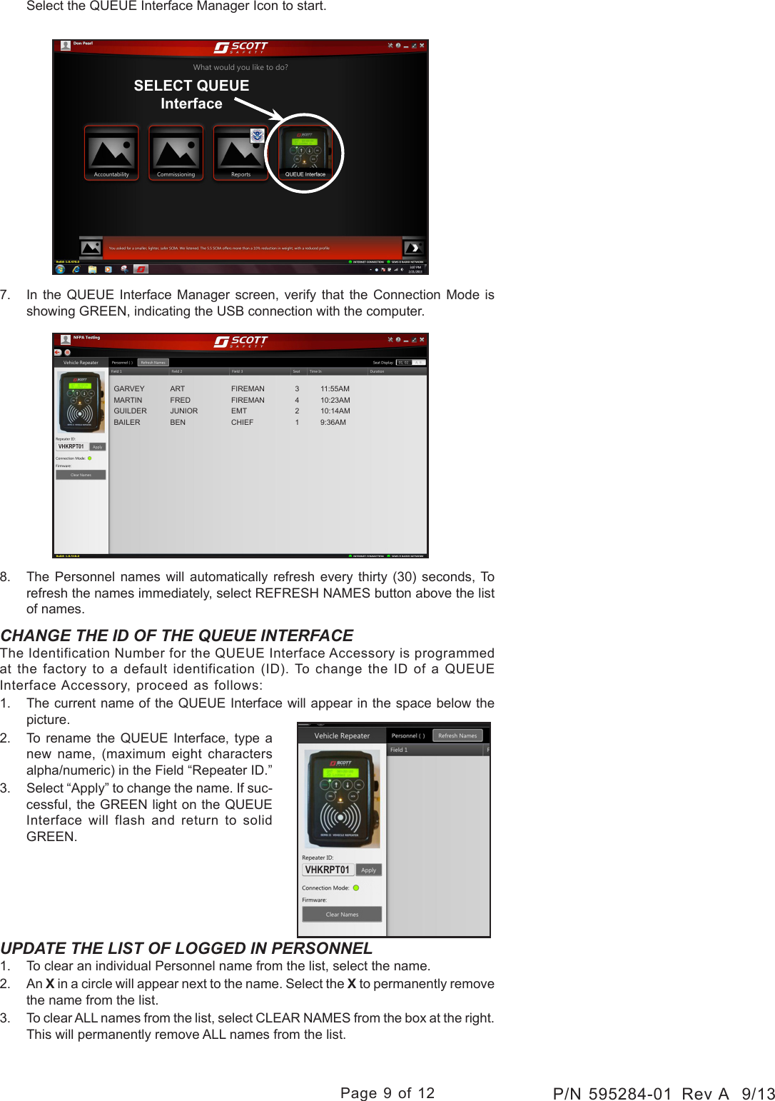
manual
Navigation menu
Upload a User Manual
Namespaces
Wiki Guide
HTML
PDF
Info
Views
User Manual
Discussion / Help
Navigation