3M Scott Technologies 201211 Queue Interface User Manual 595284 01 A
Scott Safety-Division of Scott Technologies, Inc. Queue Interface 595284 01 A
manual
Page 1 of 12
P/N 595284-01 Rev A 9/13
OPERATION AND MAINTENANCE INSTRUCTIONS
SCOTT CONNECT
QUEUE Interface Accessory
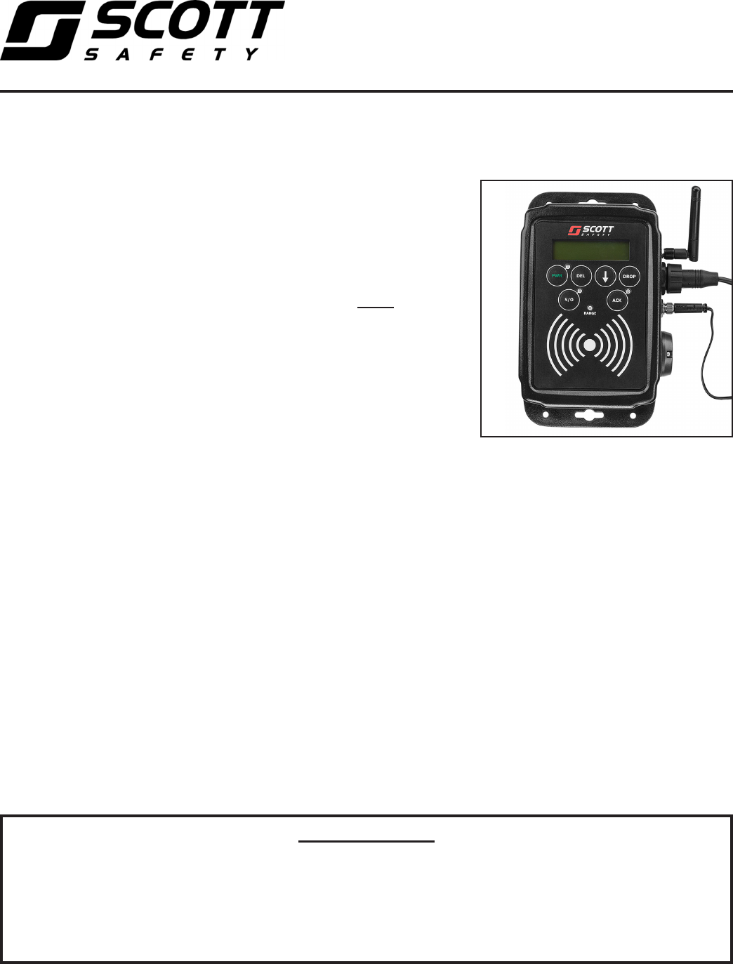
DESCRIPTION
The SCOTT CONNECT QUEUE Interface Accessory provides a log-in interface
for SCOTT IMPERIUM Accountability System users that can be associated with
a particular vehicle (such as a fire truck) at an event where accountability of
participating personnel is required. By swiping a SCOTT Accountability System
programmed ID Badge, Tag, or Button, the ID’s of up to twelve (12) users
can be stored and downloaded to the Accountability System Base Station.
The SCOTT CONNECT QUEUE Interface Accessory is ONLY compatible
with an Accountability System Base Station that is using either a PCMCIA
Gateway, SCOTT P/N 200732-02, or a USB Gateway, SCOTT P/N 201088-02
with the IMPERIUM Accountability Software.
Resources who are not using a properly equipped SCOTT SCBA respirator
may be added to the system for accountability purposes by using SCOTT
Programmable ID Tags with either the QUEUE Interface or an RFID TAG
READER/WRITER accessory. Resources added this way will not automatically
be able to receive communications from the system. Special consideration
must be given to resources who appear on the system using one of these
methods. The Base Station Operator must verify that all personnel who
appear as logged into the QUEUE Interface Accessory are actually present
at the event.
When activated, the SCOTT CONNECT QUEUE Interface Accessory appears
on the SCOTT IMPERIUM Accountability Software Base Station Display as
the identification name of the vehicle. The QUEUE Interface Accessory then
downloads to the base station the ID information of all participants who
have logged into the unit. When these individuals are included in the event
activities, they appear on the Tactical Display Screen much like a SEMS II
PDA user, except that the user details such as Air Pressure will not display.
The SCOTT CONNECT QUEUE Interface Accessory can be placed up to
seven tenths (0.7) mile line-of-sight from the base station. When logged on,
all the SEMS II Personal Distress Alarms (PDA’s) Portable Units communicate
to the Base Station directly and/or through other logged on units forming a
communications “mesh network” to the Base Station. The SCOTT CONNECT
QUEUE Interface Accessory extends the range for the PDA’s by providing
another network location to communicate with the Base Station. Because of
this mesh network system, the signal strength of each user as displayed on
the Base Station may change as the network constantly re-adjusts to the
movement of the users. For identification purposes, the SCOTT CONNECT
QUEUE Interface Accessory comes factory programmed with an eight digit
ID number that will be displayed. This default number can be reprogrammed.
Refer to the UPDATE QUEUE Interface ID section of this instruction for details.
© 2013 Scott Safety.
SCOTT, the SCOTT SAFETY Logo, Scott Health and Safety, SEMS, IMPERIUM, and QUEUE are registered and/or unregistered
marks of Scott Technologies, Inc. or its afliates.
WARNING
THE SCOTT ACCOUNTABILITY SYSTEM IS INTENDED FOR USE WITH PROPERLY EQUIPPED SCOTT SELF-CONTAINED
BREATHING APPARATUS (SCBA) WHICH MAY SUPPORT HUMAN LIFE IN HAZARDOUS ATMOSPHERES. FAILURE TO CAREFULLY
READ AND UNDERSTAND THE FOLLOWING INSTRUCTIONS MAY RESULT IN SERIOUS INJURY OR DEATH TO THE SCBA USER.
USE OF THE SCOTT CONNECT QUEUE INTERFACE ACCESSORY WILL REQUIRE MODIFICATION OF THE RESPIRATOR
"REGULAR OPERATIONAL INSPECTION PROCEDURES" AND WILL REQUIRE TRAINING OF THE RESPIRATOR USER IN THE
USE OF SUCH EQUIPMENT.
THE FOLLOWING INSTRUCTIONS SUPPLEMENT BUT DO NOT REPLACE THE OPERATING AND MAINTENANCE INSTRUCTIONS
SUPPLIED WITH EACH RESPIRATOR.
CAUTION
ONLY THE -02 VERSIONS OF THESE SCOTT
GATEWAYS WILL OPERATE WITH THE
IMPERIUM SOFTWARE AND PROVIDE FULL
FUNCTIONALITY OF THE SYSTEM FEATURES
AND THE QUEUE INTERFACE ACCESSORY.
DO NOT USE WITH THE -01 VERSIONS
OF THESE ITEMS. IF YOU HAVE THE -01
VERSIONS OF THESE GATEWAYS, CONTACT
SCOTT OR YOUR SCOTT DISTRIBUTOR FOR
DETAILS.
WARNING
SPECIAL CONSIDERATION MUST BE GIVEN
TO RESOURCES WHO APPEAR ON THE
SYSTEM USING ONE OF THE TAG READING
METHODS. THE BASE STATION OPERATOR
MUST VERIFY THAT ALL PERSONNEL WHO
APPEAR AS LOGGED INTO THE QUEUE
INTERFACE ACCESSORY ARE ACTUALLY
PRESENT AT THE EVENT. FAILURE TO
DO SO MAY RESULT PRESENTATION OF
INACCURATE INFORMATION WHICH COULD
LEAD TO SERIOUS INJURY OR DEATH.
Page 2 of 12
P/N 595284-01 Rev A 9/13
INSTALLATION OF THE
SCOTT ACCOUNTABILITY SYSTEM
QUEUE INTERFACE ACCESSORY
The QUEUE Interface Accessory, SCOTT P/N 201211-01, must be properly
installed and powered to operate correctly.
If you have any questions about installing the QUEUE Interface assembly, consult a qualied
electrician before proceeding.
1. Choose a suitable location for the QUEUE Interface Accessory:
a) Mount the assembly will be readily accessible but will not pose a hazard to
occupants of the vehicle.
b) Choose a location where the QUEUE Interface Accessory will not be exposed
to excess moisture.
c) The mounting surface should be at so that tightening the mounting screws
will not bend or stress the back plate of the QUEUE Interface.
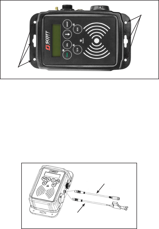
2. Place the QUEUE Interface Accessory in the desired position and mark the six
(6) mounting holes through the two mounting tabs on the housing.
WARNING
WHEN INSTALLING WITHIN A VEHICLE,
DO NOT MOUNT THE QUEUE INTERFACE
ACCESSORY IN A LOCATION WHERE IT
MAY PRESENT A HAZARD TO OCCUPANTS
OF THE VEHICLE. FAILURE TO PROPERLY
LOCATE AND PROPERLY MOUNT THE
QUEUE INTERFACE ASSEMBLY MAY RESULT
IN SERIOUS INJURY.
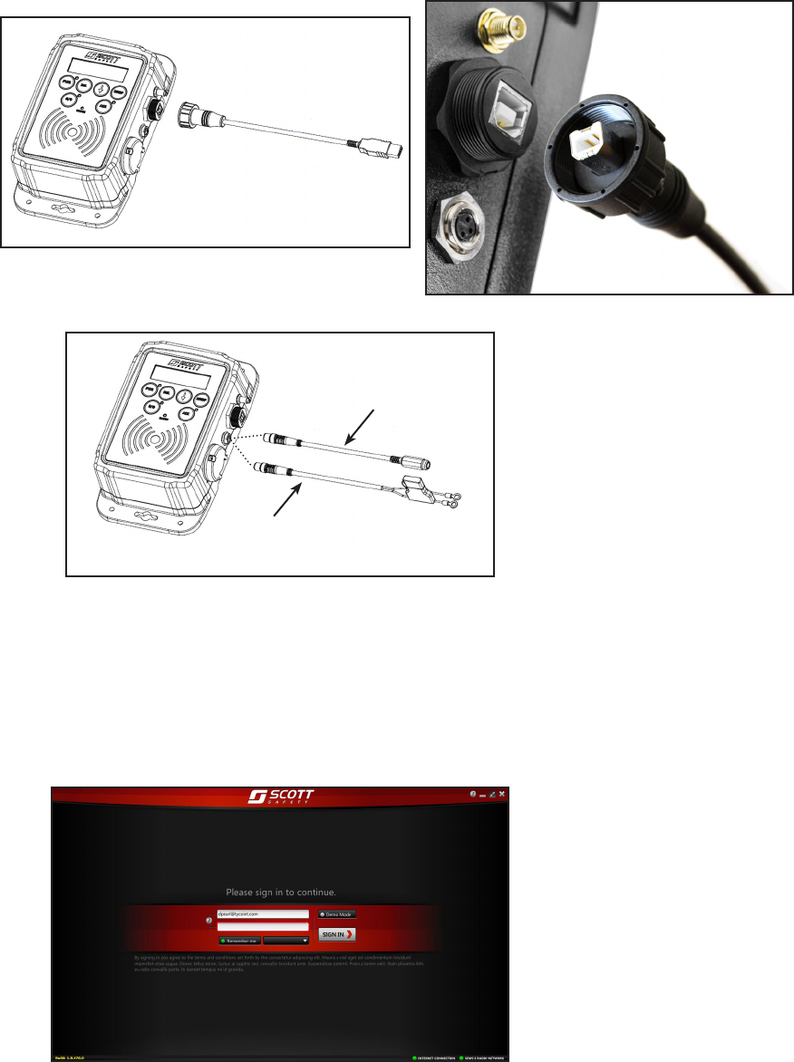
CONNECT THE POWER (TWO VERSIONS)
UNIVERSAL POWER
CORD (CONNECT
TO POWER SUPPLY)
HARD WIRE POWER CORD
(CONNECT TO VEHICLE
12V or 24V POWER)
3. When installed in a vehicle, the QUEUE Interface Accessory must be securely
mounted in either a vertical or horizontal position using the mounting holes pro-
vided. Use #10 at head machine screws in a minimum of four (4) of the holes
(two on each end). Recommended torque is 2.5 ft-lbs. or 30 inch-lbs.
4. Power supply considerations:
a) For use with the 100–240 VAC power converter, use only QUEUE Interface
Wall Power Assembly P/N 201332-01. Choose a location for mounting the as-
sembly where the power source necessary can be reached within the length
of the power supply cord which is approximately six (6) feet.
b) When powered by 12 VDC supplied from the vehicle, use only SCOTT Hard
Wire Power Cord P/N 201222-01. Attach the ring terminals to the appropriate
power terminals on the vehicle. The Hard Wire Power Cord is approximately
12 feet long and is equipped with an in-line fuse which uses a blade style low-
voltage 2 amp fuse, SCOTT P/N 31002883.
MOUNTING
HOLES
MOUNTING
HOLES
CAUTION
THE QUEUE INTERFACE ACCESSORY
MUST BE INSTALLED AT LEAST THREE (3)
FEET AWAY FROM WHERE AN RFID CARD
READER/WRITER MAY BE USED. CLOSE
PROXIMITY OF THE QUEUE INTERFACE MAY
CAUSE THE RFID CARD READER/WRITER
TO MALFUNCTION. FAILURE TO RECOGNIZE
A MALFUNCTION OF THE RFID CARD
READER/WRITER AND TAKE THE PROPER
CORRECTIVE ACTION MAY RESULT A FAILED
READ/WRITE OF THE RFID BADGE.
Page 3 of 12
P/N 595284-01 Rev A 9/13
WARNING
WHEN MOUNTING THE QUEUE INTERFACE
ACCESSORY, SECURE THE ENTIRE LENGTH
OF THE POWER SUPPLY CORD OR WIRING
SO IT DOES NOT CAUSE A TRIPPING
OR ENTANGLEMENT HAZARD. PROTECT
THE CORD OR WIRING FROM EDGES OR
CORNERS THAT MAY CAUSE IT TO FRAY
OVER TIME. FAILURE TO PROPERLY SECURE
THE POWER SUPPLY CORD OR WIRING MAY
RESULT IN SERIOUS INJURY OR DEATH.
CONNECT THE ANTENNA
WARNING
WHEN INSTALLING THE QUEUE INTERFACE
ACCESSORY, USE ONLY THE ANTENNA
PROVIDED. USE OF ANY OTHER ANTENNA
WILL VOID THE FCC APPROVAL AND MAY
REDUCE THE PERFORMANCE OF THE
EQUIPMENT WHICH MAY RESULT IN SERIOUS
INJURY OR DEATH.
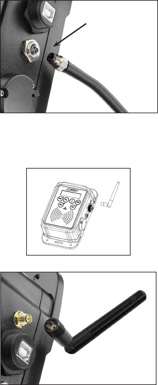
5. Align the pins in the connector with the socket and thread the collar on until snug.
Use no tools to tighten.
6. All wiring must be secured and must not provide a hazard to tripping or entangle-
ment in the chosen location. All wiring must be protected to prevent abrasion or
other damage.
7. Install the 2.4 GHZ Antenna, SCOTT P/N 31002537 by threading it onto the
antenna connector as shown in FIGURE X. Antenna should be nger tight. Use
no tools to tighten.
8. When the QUEUE Interface Accessory is connected to power, use the power
button to activate the unit and test it according to the REGULAR OPERATIONAL
INSPECTION section of this instruction.
ALIGN PINS --
THREAD IN COLLAR

Page 4 of 12
P/N 595284-01 Rev A 9/13
USE OF THE ACCOUNTABILITY SYSTEM QUEUE
INTERFACE
The organization using the QUEUE Interface must establish their own procedures for
personnel accountability using the SCOTT CONNECT Accountability System including
a REGULAR OPERATIONAL INSPECTION to verify that the unit is working properly.
Fireghter Resources who are not using a properly equipped SCOTT SCBA respirator
may be added to the system for accountability purposes by using SCOTT Program-
mable ID Tags with the QUEUE Interface accessory.
Three programmable ID’s are available:
1. The ID Badge -- usually with an individual’s name and photo on it.
2. The ID Tag -- a plastic tag that can be attached to a helmet or strap.
3. The ID Button -- a plastic button that can be sewn into a garment such as inside
a sleeve.
RFID
BADGE
RFID
TAG
RFID
BUTTON
Resources added this way will not be automatically able to receive communications
from the system. Special consideration must be given to resources who appear on
the system using one of these methods.
Any Fireghter Resources logged into the QUEUE Interface accessory will be added
to the accountability system when the QUEUE Interface comes within range of ac-
tive Base Station. The event commander must therefore conrm that all Fireghter
Resources logged into the QUEUE Interface actually arrived at the scene of the event.
WARNING
SPECIAL CONSIDERATION MUST BE GIVEN
TO RESOURCES WHO APPEAR ON THE
SYSTEM USING ONE OF THE TAG READING
METHODS. THE BASE STATION OPERATOR
MUST VERIFY THAT ALL PERSONNEL WHO
APPEAR AS LOGGED INTO THE QUEUE
INTERFACE ACCESSORY ARE ACTUALLY
PRESENT AT THE EVENT. FAILURE TO
DO SO MAY RESULT PRESENTATION OF
INACCURATE INFORMATION WHICH COULD
LEAD TO SERIOUS INJURY OR DEATH.
Page 5 of 12
P/N 595284-01 Rev A 9/13
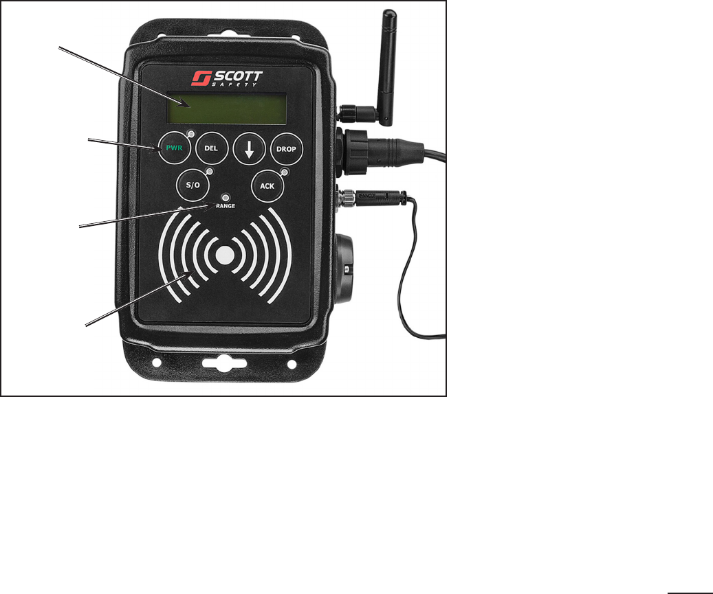
DESCRIPTION OF THE CONTROLS
• The PWR or Power Button activates the unit for use. The unit must be
on to SWIPE IN or OUT and to communicate with the IMPERIUM Ac-
countability System Base Station.
• The RANGE Light glows GREEN to indicate when the QUEUE Interface is
communicating with the Accountability System Base Station. The RANGE
Light will show YELLOW if the Unit is out of range and not connected
to an active Base Station. After two (2) minutes, the light will go out.
• The opening DISPLAY shows the current time and the Total Number of
individuals who have logged into the QUEUE Interface.
• The DOWN ARROW scrolls the Display through the list of logged-in indi-
viduals. When it reaches the end of the list, the scroll will begin again at
the top of the list. If no action is taken after five (5) seconds, the Display
returns to the opening screen.
• The DEL or Delete Button is used to remove an individual from the list
(Manually Log Out).
• The DROP Button is used to remove the entire QUEUE Interface group
from the Base Station (as if the vehicle was leaving the scene). Press
and hold the DROP button (2 to 3 seconds).
• The S/O or Swipe Out Button. See below.
• The ACK or Acknowledge Button is used to respond to an EVAC message
sent to the QUEUE Interface. The display will show EVAC and produce
a loud Warning Sound. The individual designated to monitor the loca-
tion of resources logged into that QUEUE Interface must verify that all
resources have received the message to EVACUATE before pressing
the ACK button to send an Acknowledge message to the Accountability
System Base Station and silence the Warning Sound.
• The SWIPE AREA is used to either log in or log out to the QUEUE
Interface.
• If the QUEUE Interface is removed on the current Accountability System
Base Station, the RANGE light will show YELLOW as the QUEUE Inter-
face searches for another Base Station to communicate with. If no other
Base Station if found and the QUEUE Interface will reconnect with the
current Base Station and reappear as an available resource.
RANGE
LIGHT
DISPLAY
POWER
BUTTON
SWIPE
AREA
WARNING
TRAINING IS REQUIRED BEFORE USE OF THIS
EQUIPMENT IN A HAZARDOUS SITUATION. THE
TRAINING MUST INCLUDE AN UNDERSTANDING
OF THE LIMITATIONS OF THE EQUIPMENT
ALONG WITH EXTENSIVE PRACTICE WITH THE
SYSTEM IN A VARIETY OF ENVIRONMENTS.
USE OF THIS EQUIPMENT MUST BE A PART OF
A COMPLETE PERSONNEL ACCOUNTABILITY
SYSTEM. ALWAYS UPDATE TRAINING WITH
EACH NEW PIECE OF EQUIPMENT. USE OF
THIS EQUIPMENT WITHOUT PROPER TRAINING
MAY PLACE THE USERS AT HIGHER RISK IN
DANGEROUS SITUATIONS WHICH COULD
RESULT IN SERIOUS INJURY OR DEATH.
USE OF THE ACCOUNTABILITY SYSTEM QUEUE INTERFACE
CONTINUED ON NEXT PAGE...
WARNING
THE BASE STATION CANNOT COMMUNICATE
BACK TO THE QUEUE INTERFACE EXCEPT
TO SEND AN EVAC NOTICE. THE LIST OF
PERSONNEL LOGGED INTO THE QUEUE
INTERFACE CANNOT BE ALTERED FROM THE
BASE STATION WITHOUT THE USE OF A USB
CABLE MAKING A DIRECT CONNECTION TO
THE QUEUE INTERFACE. FAILURE TO ACCOUNT
FOR THIS WHEN ASSIGNING AND ACCOUNTING
FOR PERSONNEL MAY RESULT IN SERIOUS
INJURY OR DEATH.
Page 6 of 12
P/N 595284-01 Rev A 9/13
Personnel assigned to a particular vehicle should log in (SWIPE IN) to the QUEUE
Interface on that vehicle as part of their daily routine. Personnel should SWIPE OUT
or LOG OUT MANUALLY if they know they will NOT be on the vehicle if it is called
into service.
TO SWIPE IN
Be sure the Unit is ON
Place a SCOTT RFID Badge, Tag, or Button on (or no more than 1/2” above)
SWIPE area.
The unit will beep three (3) times and the name will appear in the DISPLAY.
When the unit has reached its capacity of twelve (12) users, the unit will
play a different sound to indicate that the individual has not been accepted.
TO SWIPE OUT
Be sure the Unit is ON
Press and hold the SWIPE OUT (S/O) button
Place an RFID Badge, Tag, or Button on (or no more than 1/2” above))
SWIPE Area.
An AMBER LED next to the S/O button will go on and the unit will play a
two-note descending tone.
Release the S/O button.
TO LOG OUT MANUALLY
Use the DOWN ARROW to scroll to your name. When your name appears in
the top line of the Display, press DEL and hold until the unit plays a series
of descending tones.
FAILED SCAN
If a SWIPE in OR out is unsuccessful, there will be NO FLASH and NO
SOUND.
USE WITH THE BASE STATION
1. Turn on the Base Station computer with the SCOTT IMPERIUM Accountability
Software with the PCMCIA Communications Card or USB GATEWAY Commu-
nications Interface installed. Refer to the Base Station Instructions.
2. When the QUEUE Interface Accessory establishes communication with the Base
Station, the RANGE Light on the QUEUE Interface will glow solid GREEN.
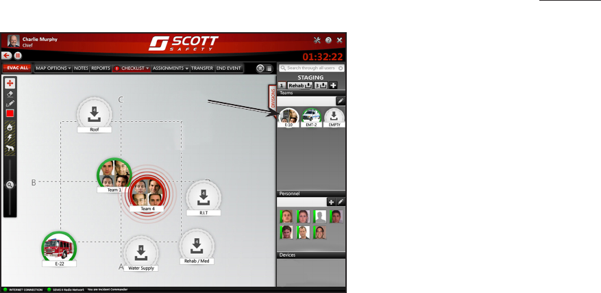
3. The QUEUE Interface will appear on the Base Station Display Screen in the
STAGING 1 SIDEBAR as a Resource with an ID number as programmed on the
QUEUE Interface (see the PROGRAMMING THE QUEUE Interface Accessory
ID section of this instruction). The QUEUE Interface will appear as a Team Icon
with a WHITE Circle surrounding it. If the QUEUE Interface goes out of range,
the Circle will change to ORANGE.
The number in the Team Icon indicates the total number logged into the QUEUE
Interface PLUS ONE for the QUEUE Interface itself.
ENTRY FOR
QUEUE Interface
USE OF THE ACCOUNTABILITY SYSTEM QUEUE INTERFACE
CONTINUED...
NOTE
AFTER THE QUEUE INTERFACE HAS
COMMUNICATED WITH THE BASE STATION,
LOGGING OUT OR SWIPING OUT ON THE
QUEUE INTERFACE WILL NOT REMOVE
THE INDIVIDUAL FROM THE ACTIVE BASE
STATION DISPLAY.
Page 7 of 12
P/N 595284-01 Rev A 9/13
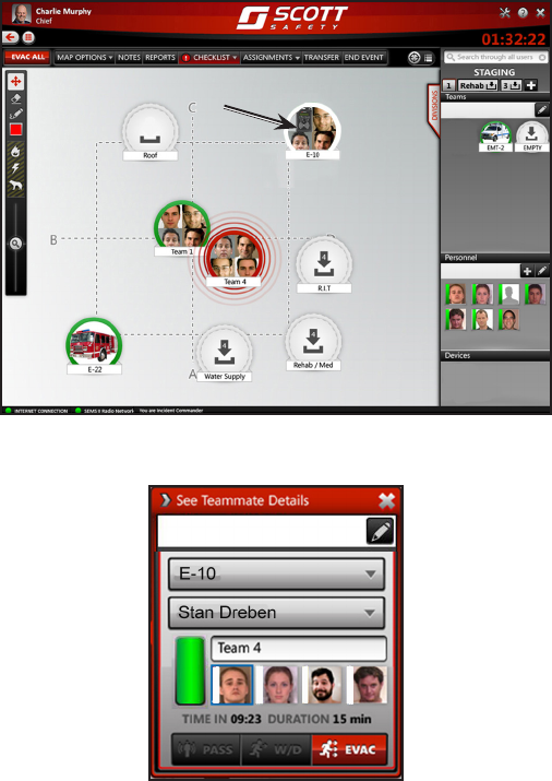
ENTRY FOR
QUEUE
INTERFACE
4. Select the QUEUE Interface from the STAGING SIDEBAR and drag it onto the
TACTICAL DISPLAY.
a) The QUEUE Interface will appear as a Team Icon.
b) Click on the Icon and it will expand to show a Team Summary.
c) Select “See Teammate Details” to see the list of individuals logged
into the QUEUE Interface. The GREEN Bar indicates that the QUEUE
Interface is in RANGE.
d) If any of the individuals logged in subsequently activate a SEMS II
PDA, their individual Teammate Detail will change to show the status
of the SCBA.
TO REMOVE INDIVIDUALS FROM THE ACTIVE DISPLAY
An individual or individuals who logged into a QUEUE Interface but did not arrive at
or participate in the event, or who are known to have left the event, can be deleted
as follows:
1. With the Entry for the QUEUE Interface showing on the TACTICAL Screen,
open the TEAM DETAILS to see all individuals who are logged into the QUEUE
Interface.
2. Click the EDIT Tool (Pencil) and SELECT the individual or individuals to be deleted
from the Entry for the QUEUE Interface.
3. Drag the selected individuals out of the Entry for the QUEUE Interface and onto
the TACTICAL DISPLAY. They will appear as a TEAM. One person will appear
as a TEAM of one.
4. Select any active STAGING Screen, (STAGING 1, STAGING 2 RE-HAB, etc.)
5. Drag the TEAM to the selected STAGING Screen.
6. In the STAGING Screen, click on the EDIT TOOL (Pencil) and select the TEAM.
7. Select REMOVE. The TEAM will be removed from the Event.
8. If any of the individuals later appear at the Event, use the SEARCH window to
enter his/her name. Select the individual's name to reinstate him/her in the Event.
Page 8 of 12
P/N 595284-01 Rev A 9/13
UPDATE THE QUEUE INTERFACE ACCESSORY
The QUEUE Interface can be accessed using a USB connection. This access per-
mits the user to change the name ID of the unit, retrieve data, or to remove logged in
names. Access requires a personal computer with the SCOTT IMPERIUM Software
and a suitable USB interface cable to connect the QUEUE Interface Unit. These ac-
tions can ONLY be performed with the USB connection.
ACCESS TO THE QUEUE INTERFACE
1. Verify that the QUEUE Interface is connected to the computer with the USB
interface cable.
2. Verify that the QUEUE Interface is connected to an active power supply.
CONNECT THE USB CABLE
CONNECT THE POWER (TWO VERSIONS)
UNIVERSAL POWER
CORD (CONNECT
TO POWER SUPPLY)
HARD WIRE POWER CORD
(CONNECT TO VEHICLE
12V or 24V POWER)
3. Start-up the personal computer in accordance with the computer’s user instruc-
tions. The computer will display a message that new hardware has been detected.
4. To open the IMPERIUM Software, select the SCOTT shortcut created on your
Desktop or in the “Tyco – Scott Safety” folder in “All Programs” in the Windows
START menu.
5. The Sign In Screen will appear. Sign In with your User Name and Password.
6. When signed in, you will see the following screen:
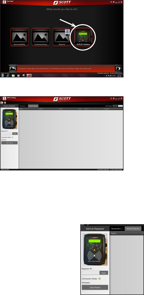
Page 9 of 12
P/N 595284-01 Rev A 9/13
Select the QUEUE Interface Manager Icon to start.
SELECT QUEUE
Interface
7. In the QUEUE Interface Manager screen, verify that the Connection Mode is
showing GREEN, indicating the USB connection with the computer.
GARVEY ART FIREMAN 3 11:55AM
MARTIN FRED FIREMAN 4 10:23AM
GUILDER JUNIOR EMT 2 10:14AM
BAILER BEN CHIEF 1 9:36AM
VHKRPT01
8. The Personnel names will automatically refresh every thirty (30) seconds, To
refresh the names immediately, select REFRESH NAMES button above the list
of names.
VHKRPT01
CHANGE THE ID OF THE QUEUE INTERFACE
The Identification Number for the QUEUE Interface Accessory is programmed
at the factory to a default identification (ID). To change the ID of a QUEUE
Interface Accessory, proceed as follows:
1. The current name of the QUEUE Interface will appear in the space below the
picture.
2. To rename the QUEUE Interface, type a
new name, (maximum eight characters
alpha/numeric) in the Field “Repeater ID.”
3. Select “Apply” to change the name. If suc-
cessful, the GREEN light on the QUEUE
Interface will flash and return to solid
GREEN.
UPDATE THE LIST OF LOGGED IN PERSONNEL
1. To clear an individual Personnel name from the list, select the name.
2. An X in a circle will appear next to the name. Select the X to permanently remove
the name from the list.
3. To clear ALL names from the list, select CLEAR NAMES from the box at the right.
This will permanently remove ALL names from the list.
Page 10 of 12
P/N 595284-01 Rev A 9/13
CLASS B DIGITAL DEVICE
Note: This equipment has been tested and found to comply with the limits for a Class
B digital device, pursuant to Part 15 of the FCC Rules. These limits are designed to
provide reasonable protection against harmful interference in a residential installation.
This equipment generates, uses and can radiate radio frequency energy and, if not
installed and used in accordance with the instructions, may cause harmful interference
to radio communications. However, there is no guarantee that interference will not
occur in a particular installation. If this equipment does cause harmful interference to
radio or television reception, which can be determined by turning the equipment off
and on, the user is encouraged to try to correct the interference by one or more of
the following measures:
– Reorient or relocate the receiving antenna
– Increase the separation between the equipment and receiver.
– Connect the equipment into an outlet on a circuit different from that to which the
receiver is connected.
– Consult the dealer or an experienced radio/TV technician for help.
FCC COMPLIANCE
FCC Compliance Statement (Part 15.19)
This device complies with Part 15 of the FCC Rules. Operation is subject to
the following two conditions:
1. This device may not cause harmful interference, and
2. This device must accept any interference received, Including interference that
may cause undesired operation.
FCC Warning (Part 15.21)
Changes or modications not expressly approved by the party responsible for compli-
ance could void the user’s authority to operate the equipment.
The SCOTT CONNECT QUEUE Interface Accessory Transmitter has been as-
signed FCC ID # T5E-201211.
RADIO FREQUENCY INTERFERENCE (RFI)
When any electronic device is adversely affected by radio waves, Radio
Frequency Interference (RFI) is said to have occurred. All electronic devices
like the SCOTT CONNECT QUEUE Interface Accessory may be subject to
the effects of RFI, most of which are temporary in nature. If RFI occurs to
the SCOTT CONNECT QUEUE Interface Accessory, it may be caused by
transmissions from hand-held or personal radios where the radio antenna
is touching or very close to (less than 6 inches from) components of the
SCOTT CONNECT QUEUE Interface Accessory. It may also be caused by
transmissions from base stations or high-powered vehicle mounted radios or
any other powerful source of electromagnetic radiation.
SAFETY LISTINGS
WARNING
RADIO FREQUENCY INTERFERENCE (RFI)
MAY CAUSE A MALFUNCTION OF THE QUEUE
INTERFACE ACCESSORY. USERS MUST BE
AWARE OF THE PROPER OPERATION OF
THE EQUIPMENT. FAILURE TO RECOGNIZE
A MALFUNCTION OF THE EQUIPMENT AND
TAKE PROPER CORRECTIVE ACTION
MAY RESULT FAILURE OF THE SCOTT
ACCOUNTABILITY SYSTEM ACCOUNTABILITY
SYSTEM AND LEAD TO SERIOUS INJURY OR
DEATH.
WARNING
WHEN INSTALLING THE QUEUE INTERFACE
ACCESSORY, USE ONLY THE ANTENNA
PROVIDED. USE OF ANY OTHER ANTENNA
WILL VOID THE FCC APPROVAL AND MAY
REDUCE THE PERFORMANCE OF THE
EQUIPMENT WHICH MAY RESULT IN SERIOUS
INJURY OR DEATH.
Page 11 of 12
P/N 595284-01 Rev A 9/13
INDUSTRY CANADA COMPLIANCE
Industry Canada Statement
The term “IC” before the certication / registration number only signies that the In-
dustry Canada technical specications were met.
Section 14 of RSS-210
The installer of this radio equipment must ensure that the antenna is located or pointed
such that it does not emit RF eld in excess of Health Canada limits for the general
population. Consult Safety Code 6, obtainable from Health Canada’s web site: www.
hc-sc.gc.ca/rpb.
To comply with FCC and Industry Canada RF radiation exposure limits for general
population, the antenna(s) used for this transmitter must be installed such that a
minimum separation distance of 20cm is maintained between the radiator (antenna)
and all persons at all times.
This Device complies with Industry Canada License-exempt RSS standard(s). Opera-
tion is subject to the following two conditions:
1) this device may not cause interference, and
2) this device must accept any interference, including interference that
may cause undesired operation of the device.
LA DÉCLARATION DE CONFORMITÉ D’INDUSTRIE DE
CANADA
Déclaration D’Industrie De Canada
Le terme avant de la certication /le nombre d’enregistrement signie seulement que
les spécications techniques d’Industrie du Canada ont été rencontrées.
Sectionner 14 de RSS-210
Le programme d’installation de cet équipement de radio doit garantir que l’antenne
est localisée ou tel est indiqué qu’il ne met pas le champ de RF dépassant les limites
de Canada de Santé pour la population générale. Consulter le Code de Sécurité 6,
procurable du site Web de Canada de Santé: www.hc-sc.gc.ca/rpb.
Pour se conformer aux règlements de la FCC et Industrie Canada limites d’exposition
au rayonnement RF pour la population générale, l’antenne(s) utilisé(s) pour cet
émetteur doit être installée de telle manière que la distance minimale de séparation
de 20 cm soit maintenue entre le radiateur (antenne) et toutes les personnes en tout
temps.
Cet appareil est conforme aux normes Industry Canada exemptes de licence RSS
standard(s). L’opération doit s’assurer de suivre deux conditions:
1) Cet appareil ne peut pas causer l’intervention, et
2) Cet appareil doit accepter de l’intervention, y compris l’intervention
qui peut causer l’opération non désirée de l’appareil.

Page 12 of 12
P/N 595284-01 Rev A 9/13
SCOTT Safety
Monroe Corporate Center
PO Box 569
Monroe, NC 28111
Telephone 1-800-247-7257
Fax (704) 291-8330
www.scottsafety.com
Printed in USA
REGULAR OPERATIONAL INSPECTION
Inspect and test the SCOTT CONNECT QUEUE Interface Accessory as part
of the REGULAR OPERATIONAL INSPECTION of the complete SCOTT Ac-
countability System. A SCOTT Accountability System Base Station and user
instruction SCOTT P/N 595290-01 are required for inspection. If any malfunc-
tion of the SCOTT CONNECT QUEUE Interface Accessory or the SCOTT
Accountability System is noted during the inspection, remove the defective
equipment from service and tag for repair by authorized personnel.
INSPECT THE QUEUE INTERFACE ACCESSORY
1. Visually inspect the QUEUE Interface Accessory for cracks, wear or other dam-
age. If any damage is found, remove the unit from service and tag for repair by
qualied personnel.
2. Test the operation of the QUEUE Interface Accessory as part of your routine
testing of the complete SCOTT Accountability System. Refer to the USE OF THE
QUEUE Interface ACCESSORY section of this instruction for details of operation.
If any malfunction of the equipment is noted, remove the equipment from
service and tag for repair by authorized personnel. Notify all personnel that
the unit is out of service and take alternate steps to account for the appli-
cable personnel.
CLEANING, MAINTENANCE,
AND STORAGE
Clean the exterior of the SCOTT CONNECT QUEUE Interface Accessory by
wiping with a damp sponge and thoroughly wiping dry. .
No attempt shall be made to do maintenance or to make adjustments or
repairs beyond the scope of this instruction manual without proper training.
WARNING
FOLLOW REGULAR OPERATIONAL INSPECTION
PROCEDURE EXACTLY. IF THE SCOTT CONNECT
QUEUE INTERFACE ACCESSORY DOES NOT
ACTUATE, OR IF ANY OTHER FEATURE DOES
NOT OPERATE AS DESCRIBED OR IF ANY
OTHER OPERATIONAL MALFUNCTION IS
NOTED, DO NOT USE THE UNIT.
EXPORT AND IMPORT
The international transport of the SCOTT Accountability System and portions thereof is
regulated under United States export regulations and may be regulated by the import
regulations of other countries.
If you have any questions or concerns regarding these regulations, contact SCOTT at
1-800-247-7257 (or 704-291-8300 outside the continental United States).
QUESTIONS OR CONCERNS
If you have any questions or concerns regarding use of this equipment, contact
your authorized SCOTT distributor, or contact SCOTT at 1-800-247-7257 (or
704-291-8300 outside the continental United States).