3M Traffic Safety Systems S2301 Automatic Vehicle Identification Transceiver User Manual IDentity Flex Installation Manual
3M Traffic Safety Systems Automatic Vehicle Identification Transceiver IDentity Flex Installation Manual
UserManual.wiki
>
3M Traffic Safety Systems
>
S2301 User Manual
manual
Navigation menu
Upload a User Manual
Namespaces
Wiki Guide
HTML
PDF
Info
Views
User Manual
Discussion / Help
Navigation


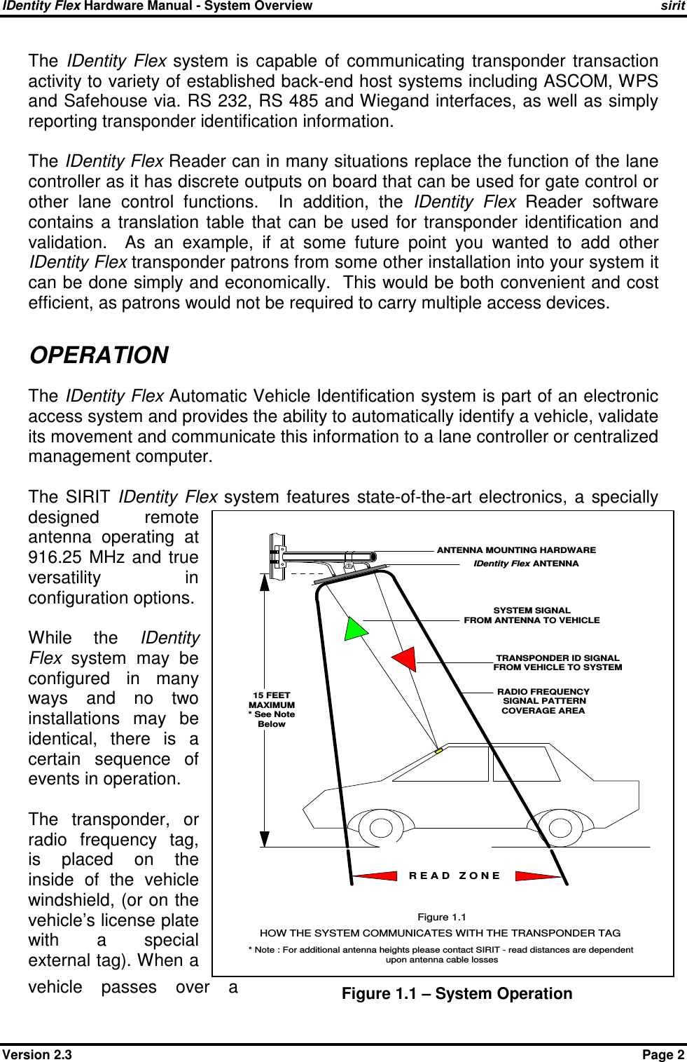


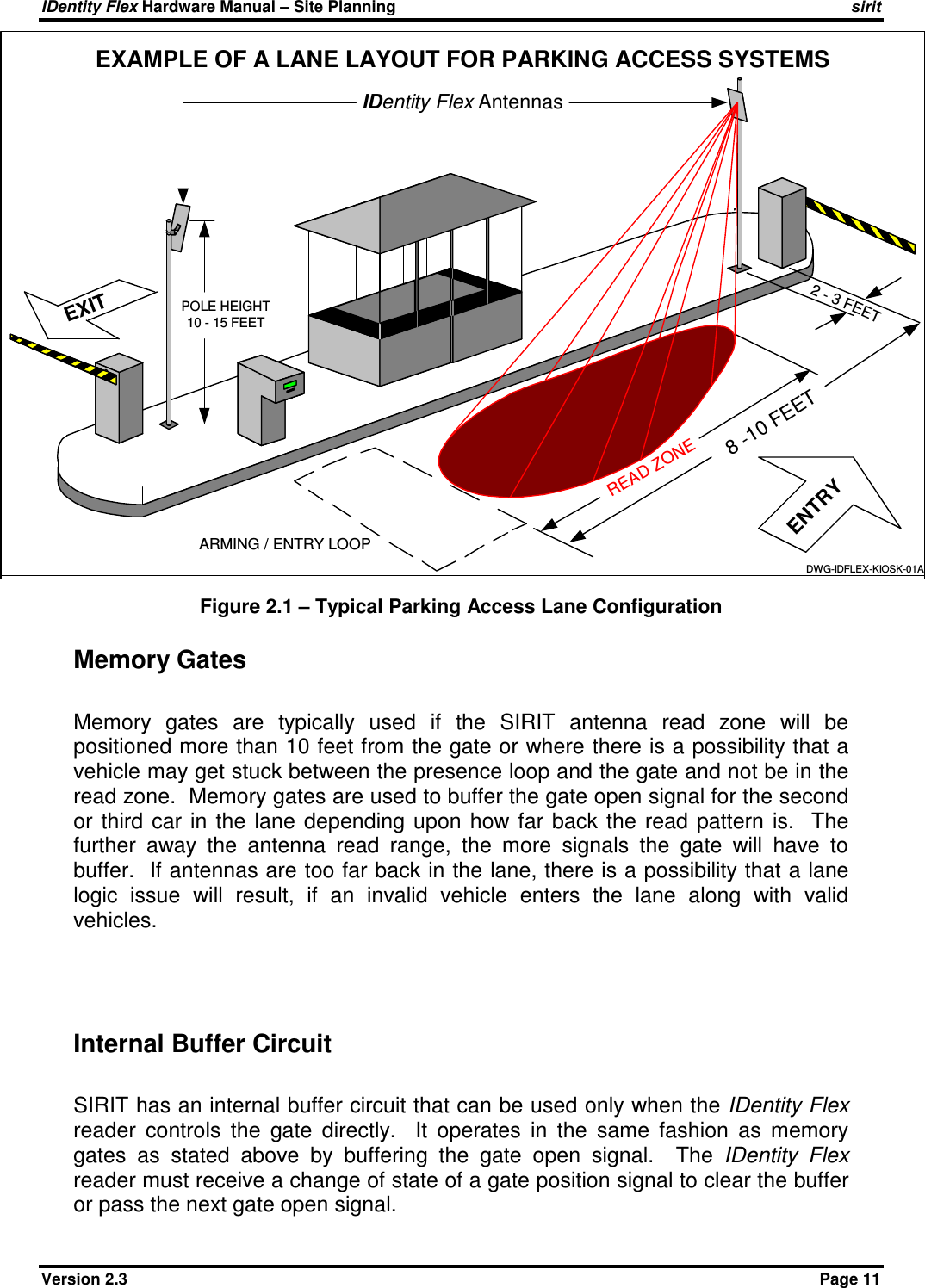
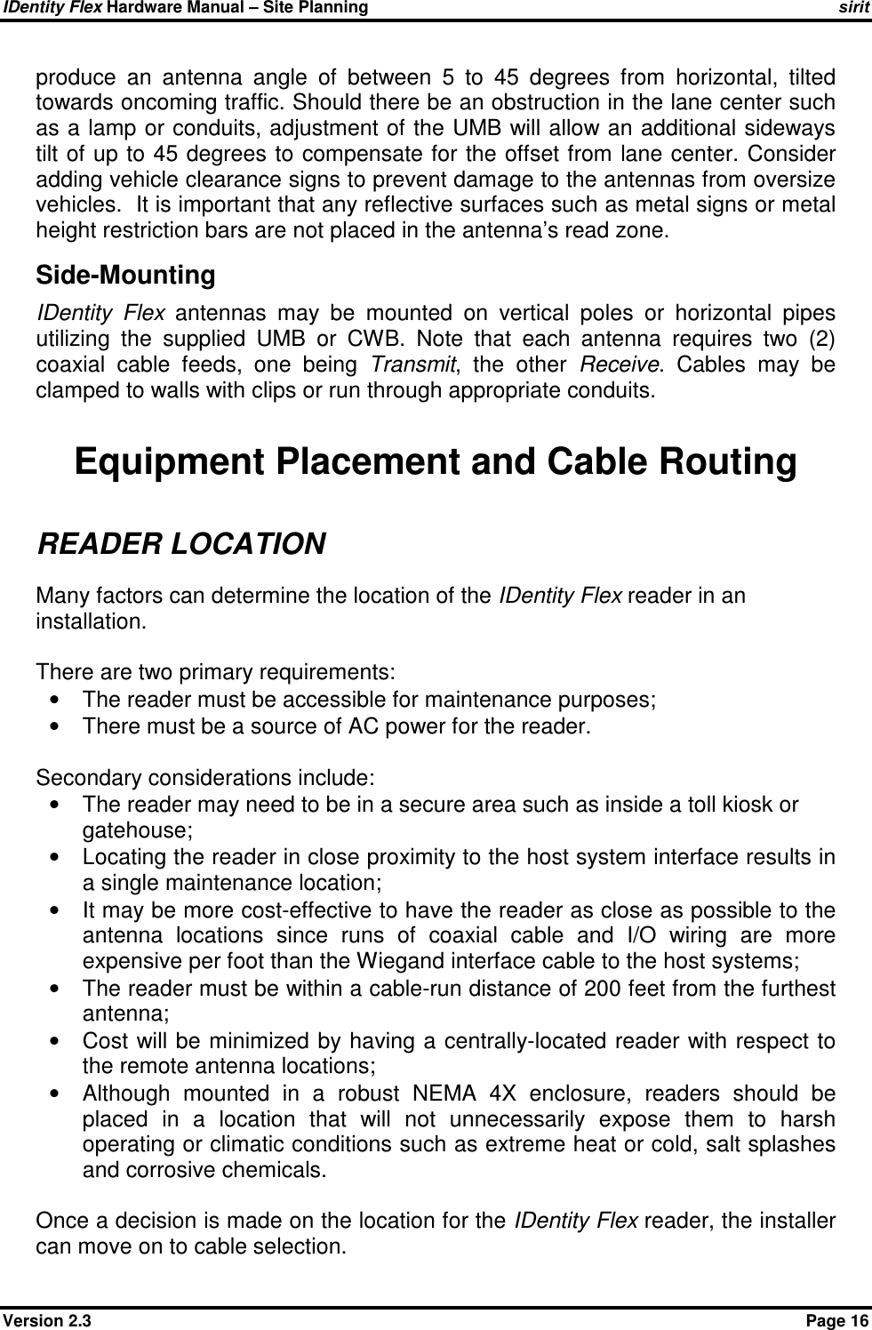
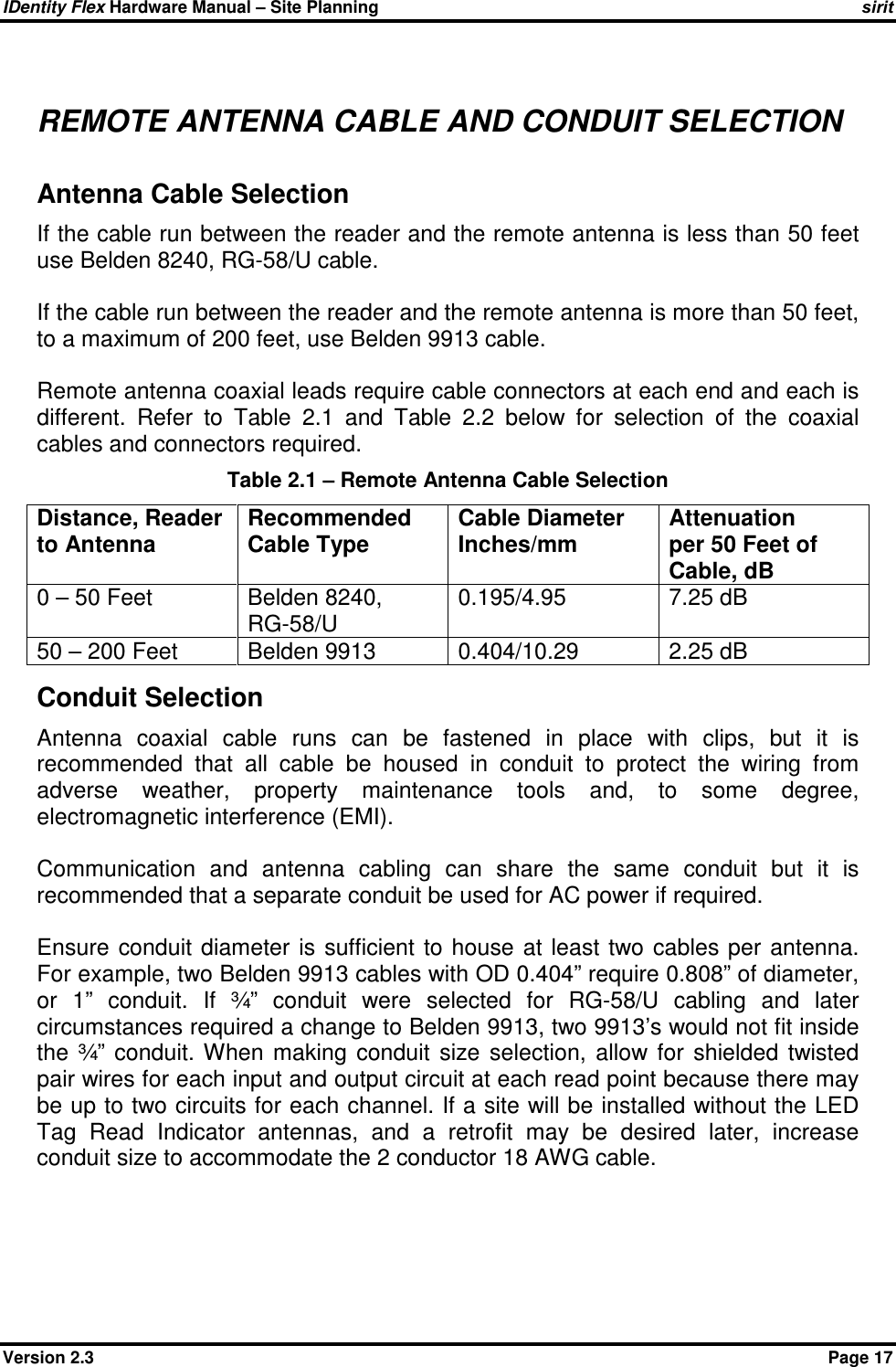
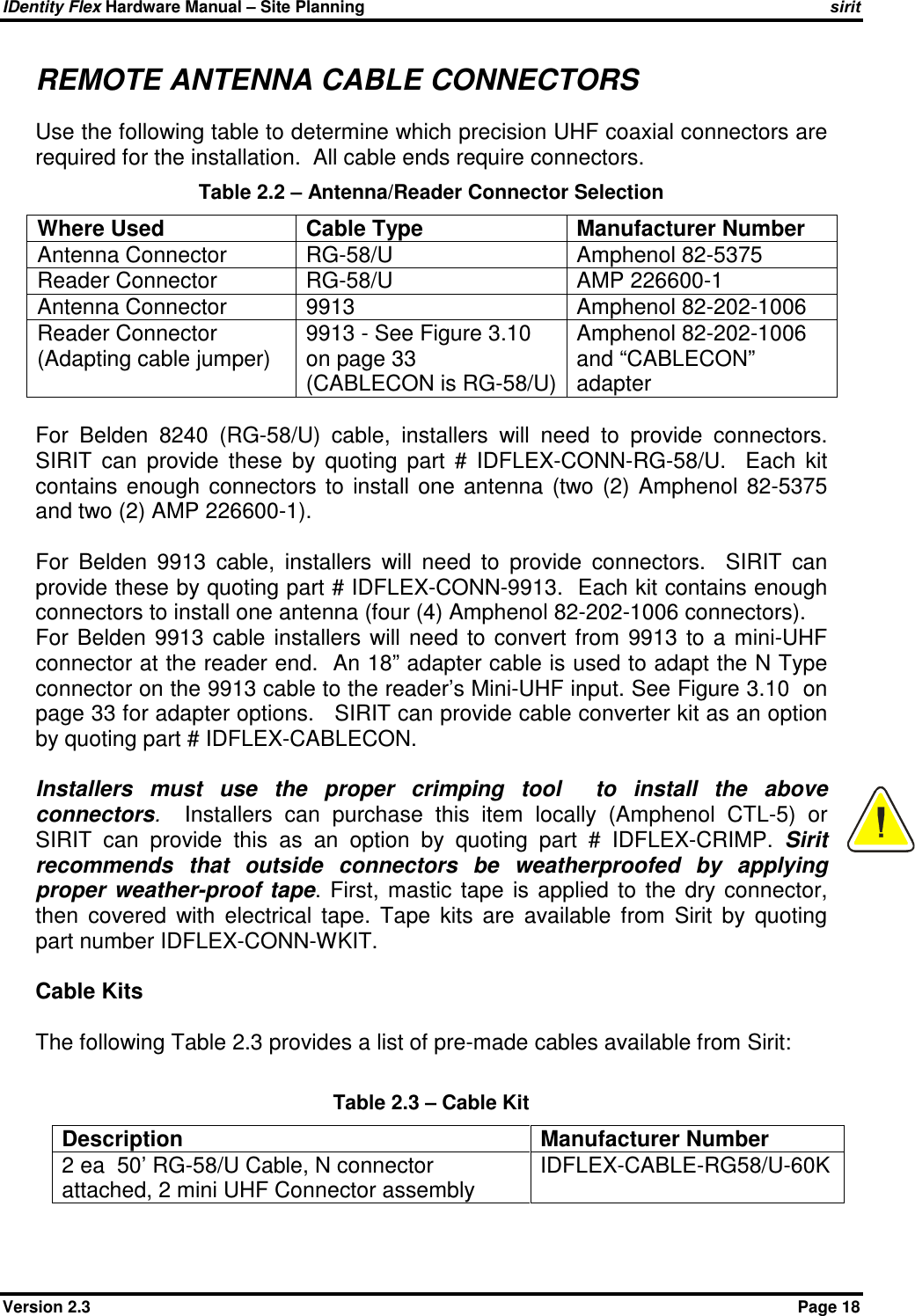
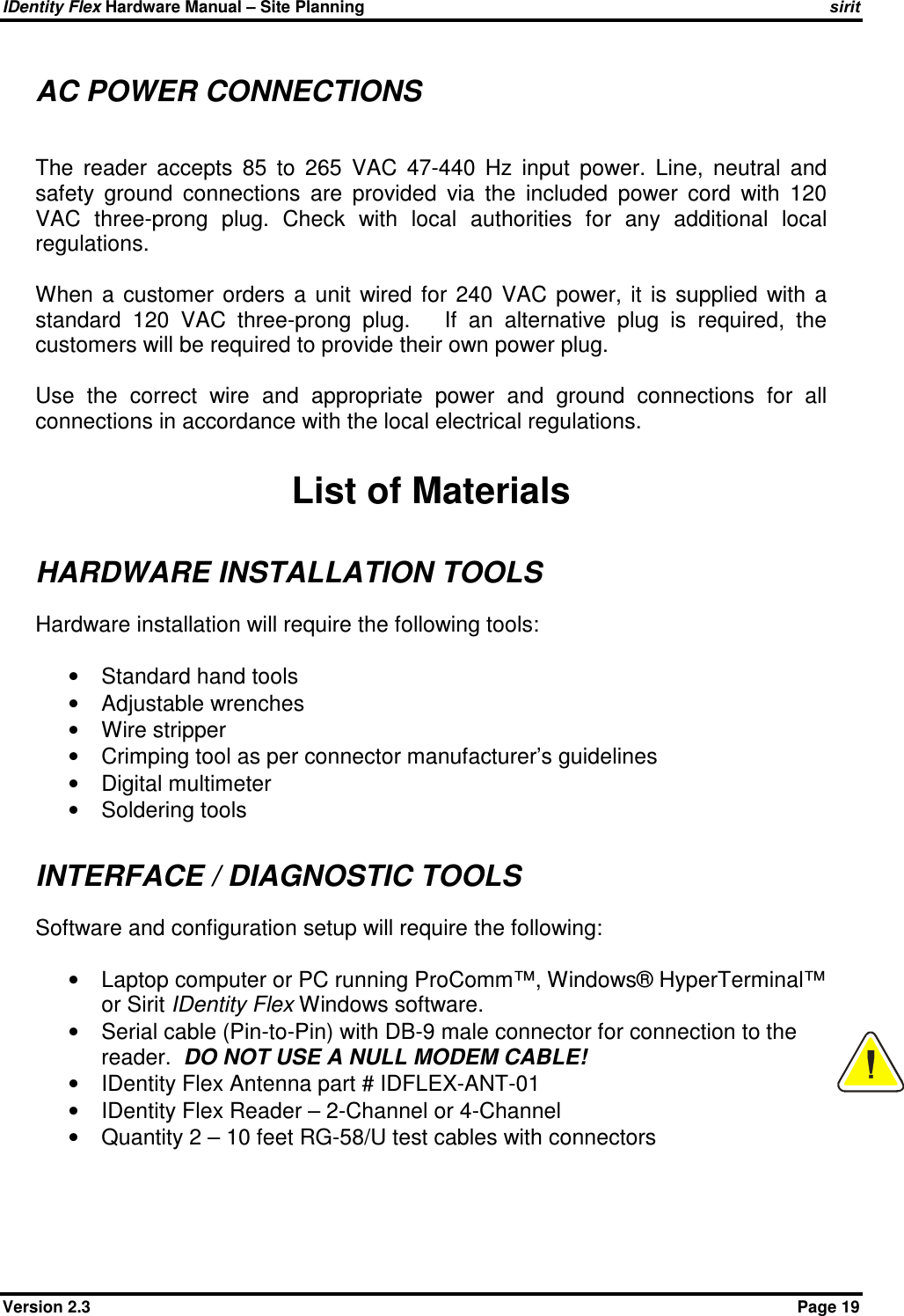


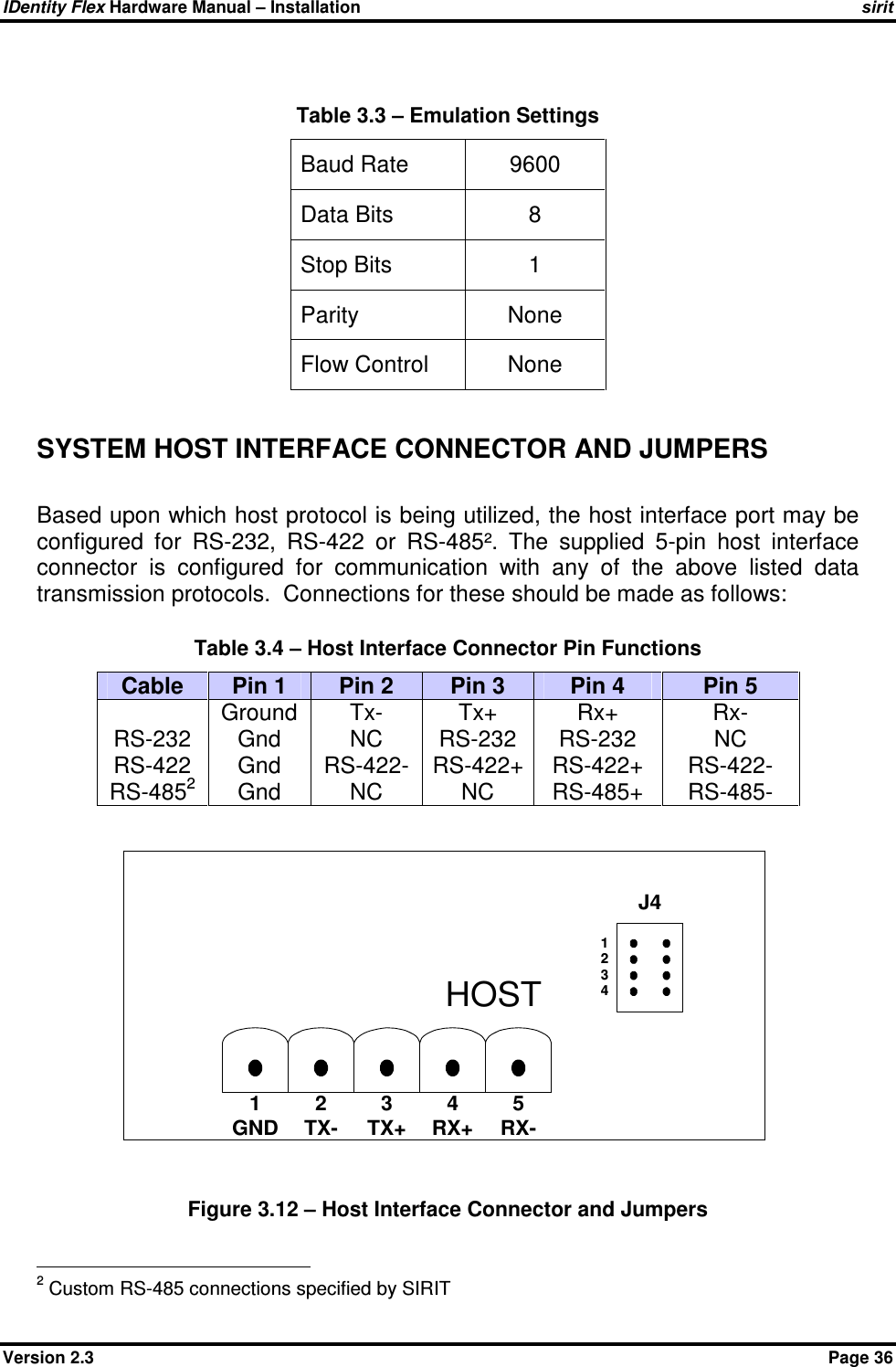


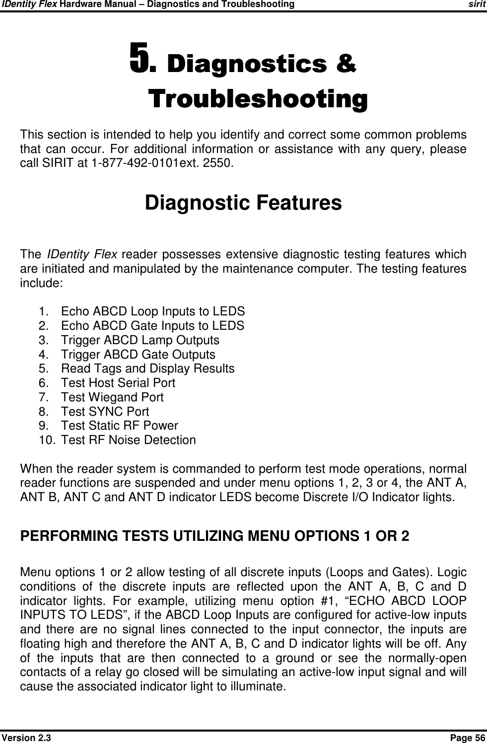
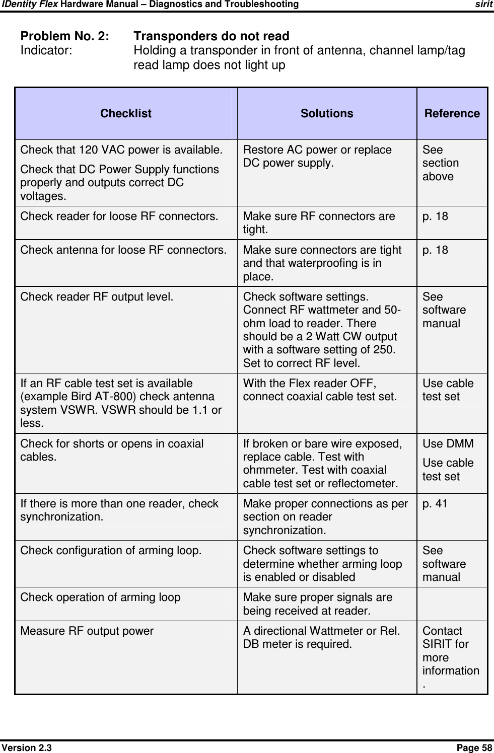
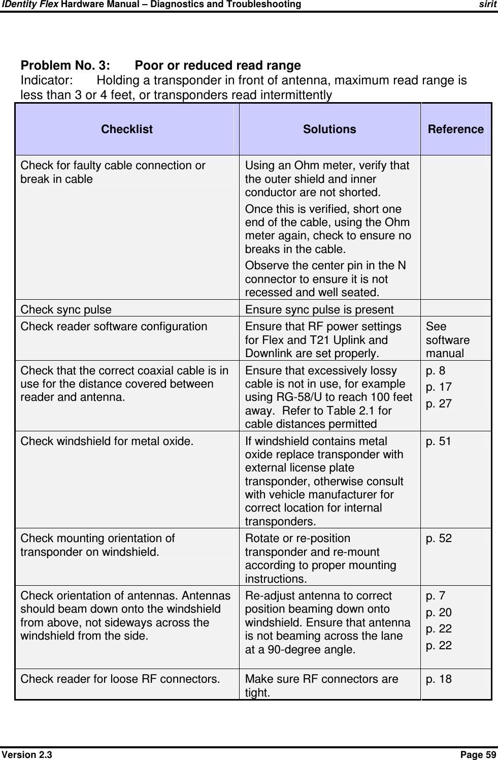
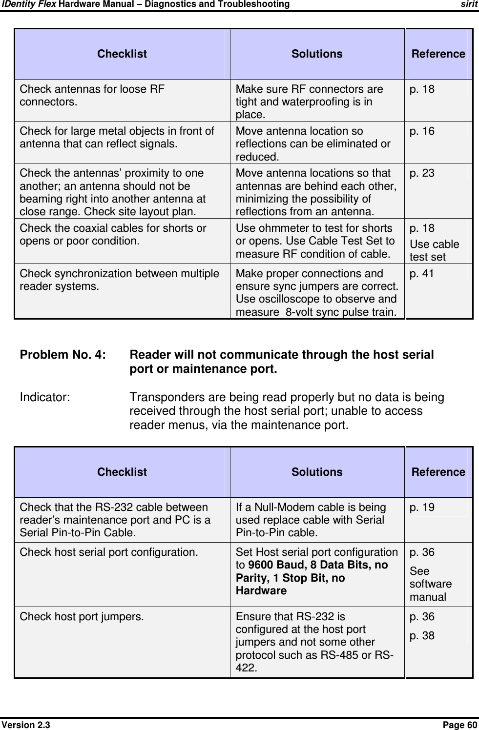
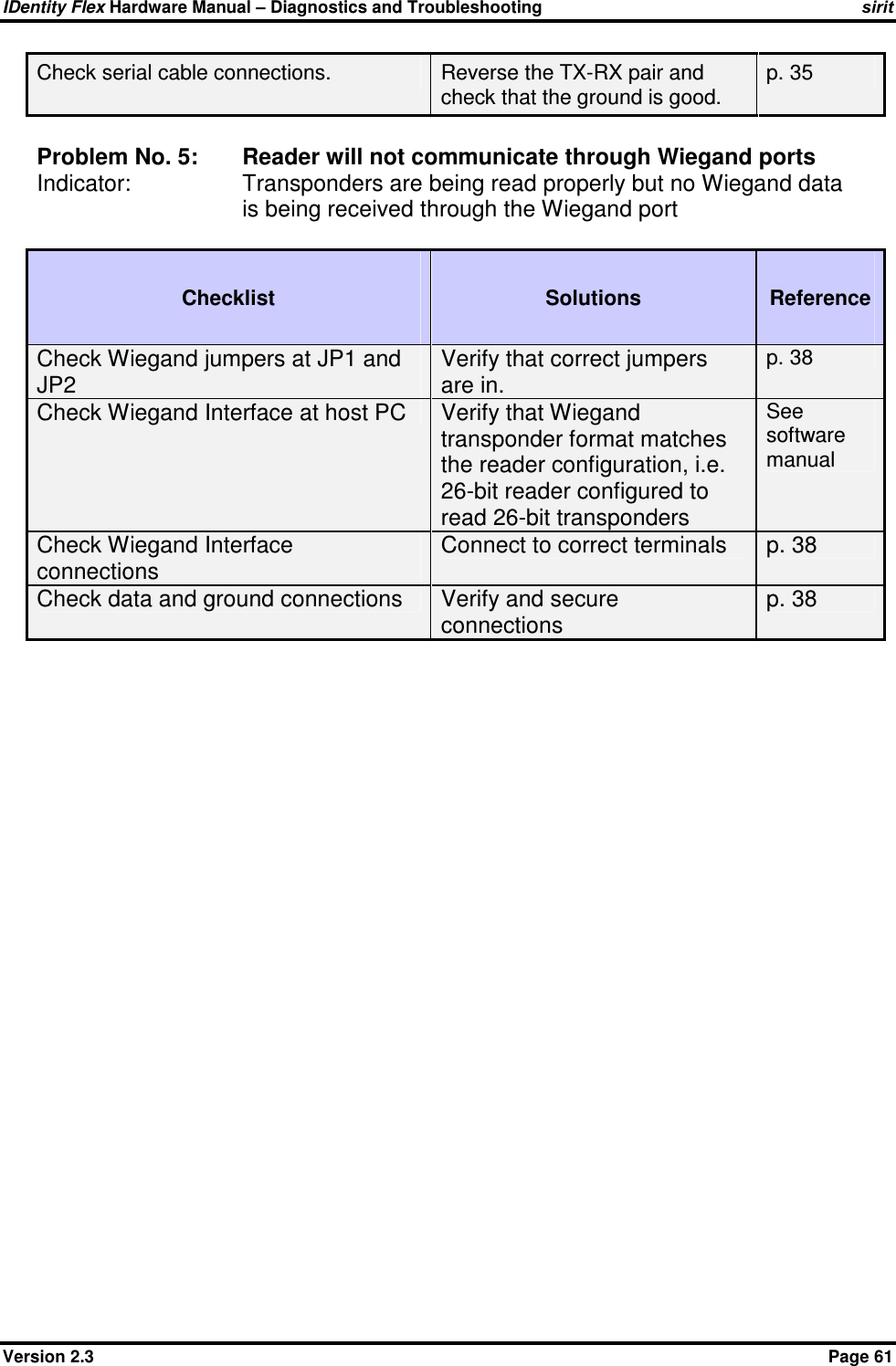
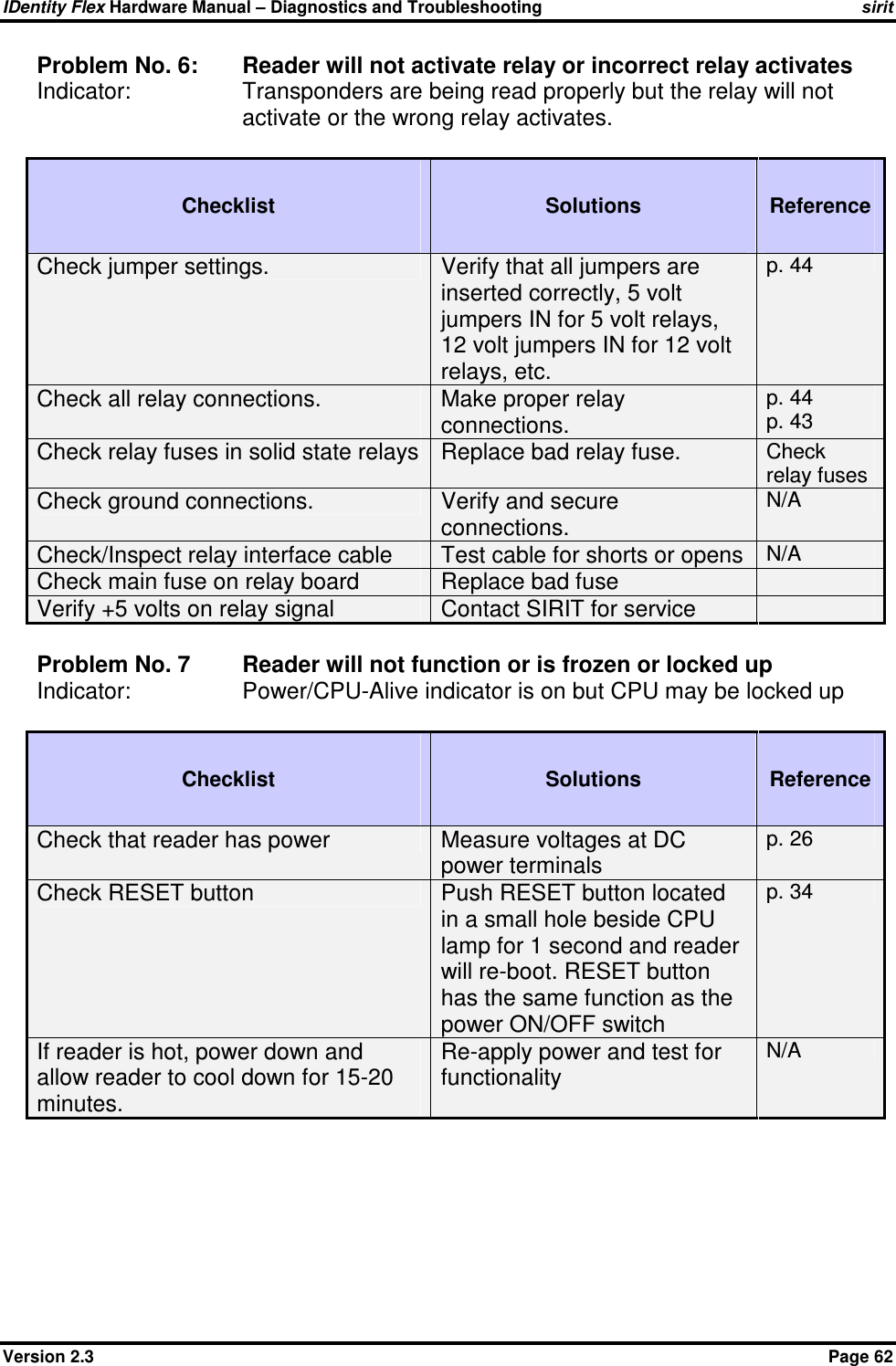
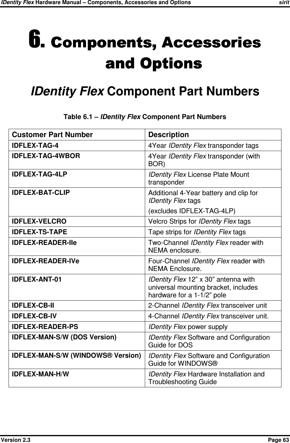
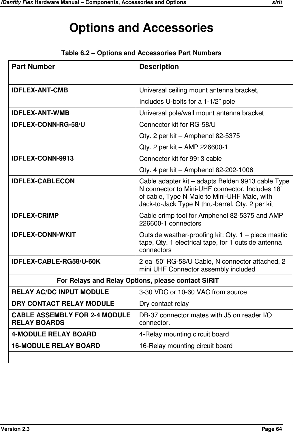
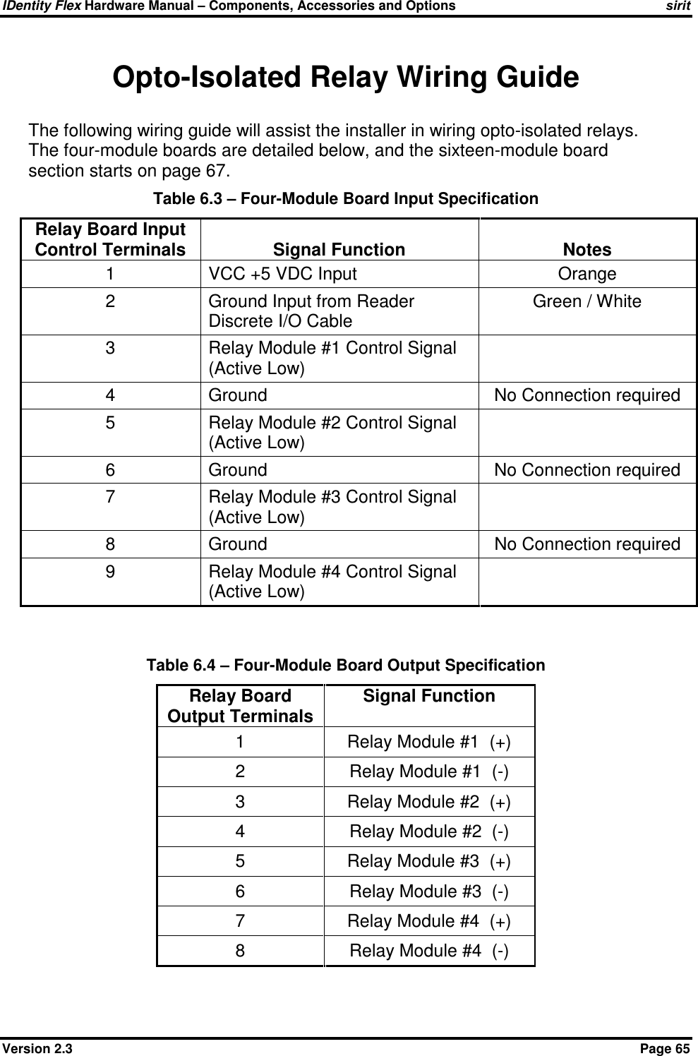
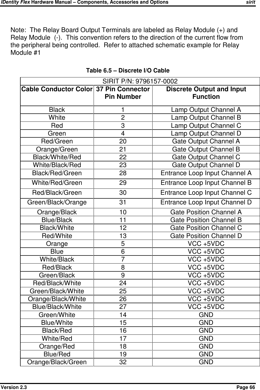
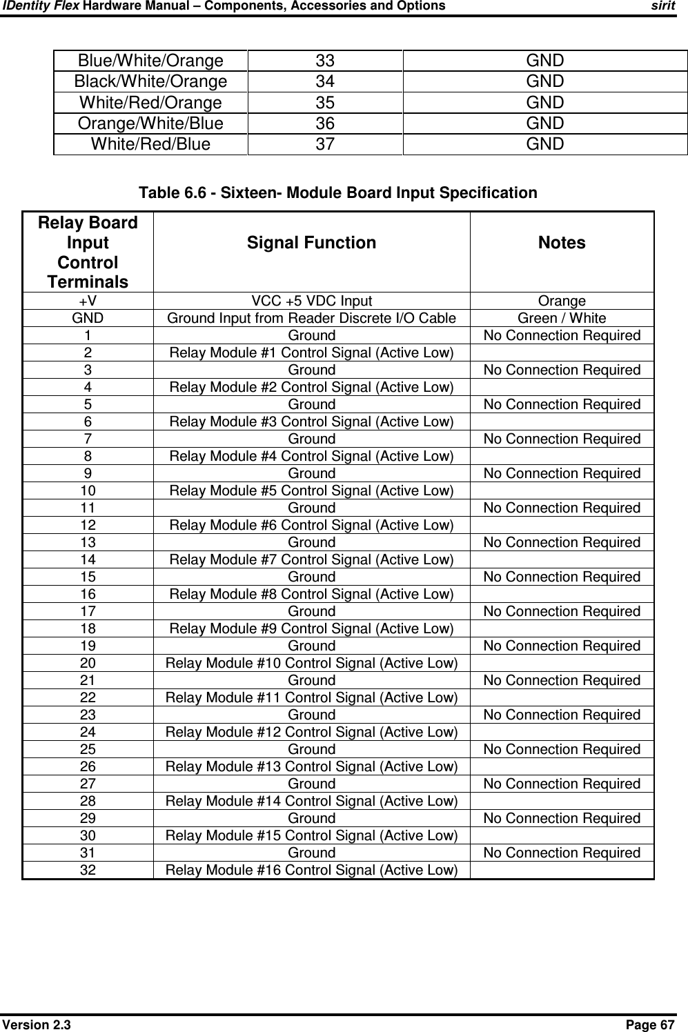
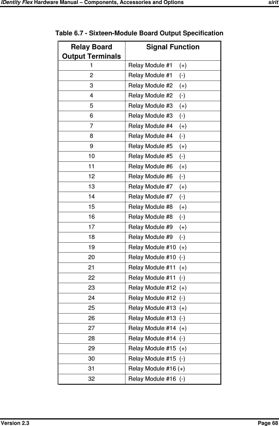
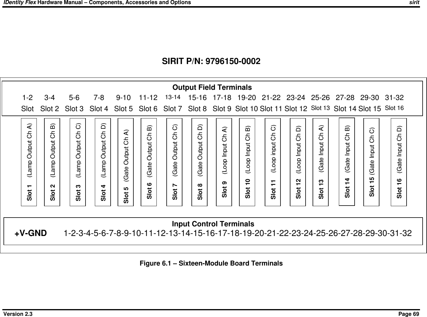
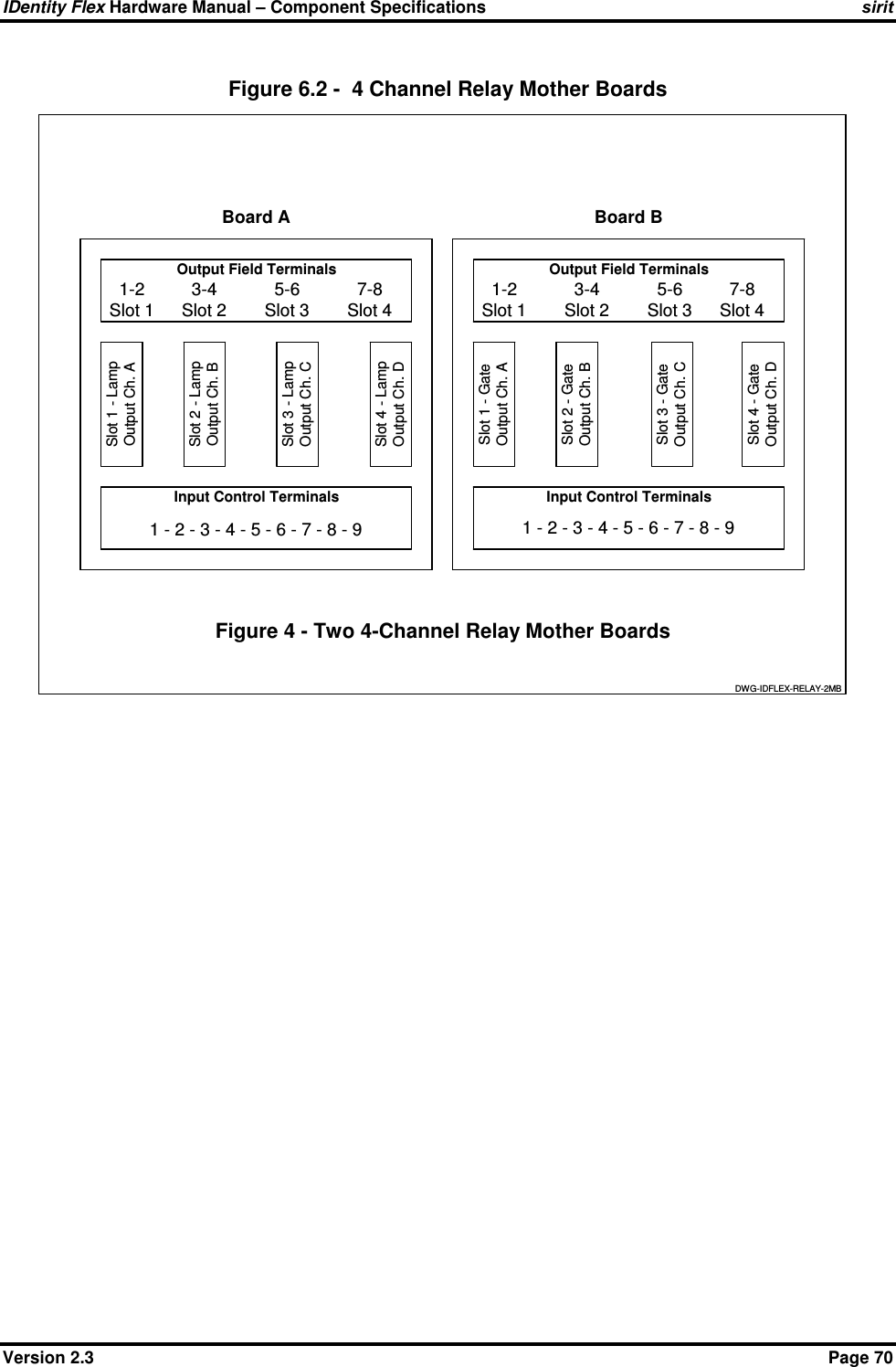
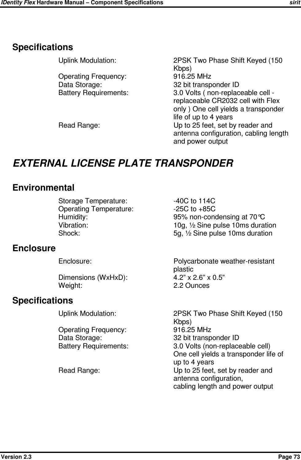
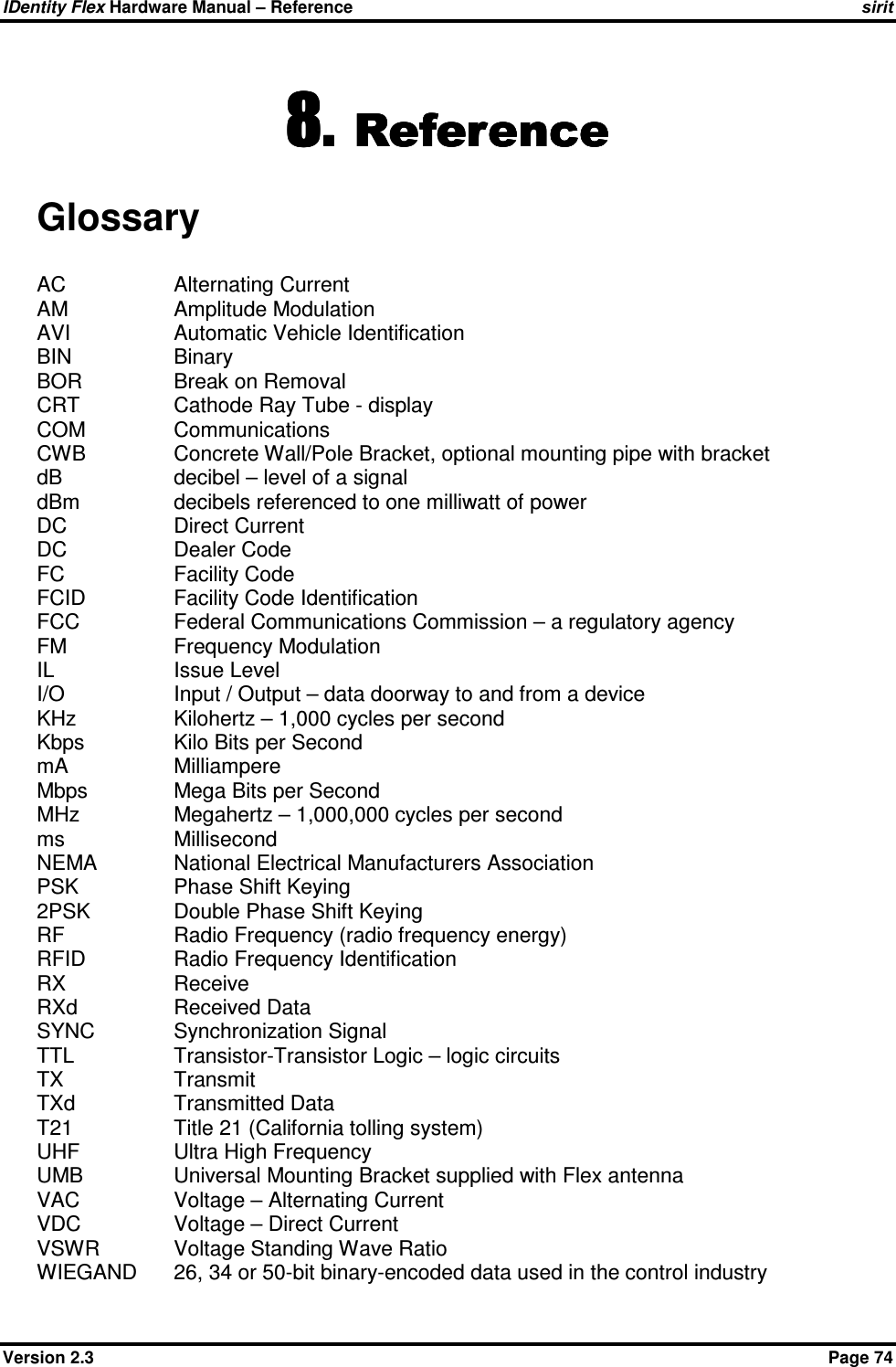
![IDentity Flex Hardware Manual – Transponder Usage sirit Version 2.3 Page 55 Conversion Procedure for T21 Transponders This conversion procedure is utilized by SIRIT’s DOS-based software to allow Title 21 (T21) transponders to be read by the IDentity Flex system. Since the IDentity Flex Reader requires each transponder ID to be in hexadecimal format they must first be converted to hex and then entered via the conversion utility, which will update the tag list file. 1.) Boot up the reader and select menu option “3 - Tag List Maintenance”. <3> <ENTER> 2.) From the Tag List menu select menu option “6 – Manually Add Tag to Update List”. <6> <ENTER> 3.) Select menu option “T” for a T21 type transponder. <T> <ENTER> 4.) At the screen option “Enter Search ID in HEX” – Enter the 8-digit number shown on the transponder’s label and <ENTER>. Another way to find this number is to have the system read the tag and then record the number that comes up on the screen. 5.) At the screen option see “Enter Translate ID in HEX”. This is the number that the customer will assign to that tag. This number must be entered in hexadecimal format so the facility code/ID or Group#/System Code/ID will need to be converted into HEX first. See example below. Input the 8-digit number and <ENTER>. o Example: o Customers Facility Code in decimal: Facility Code 200 o Customers desired transponder Number in decimal: Tag # 1201 o 200 in decimal is 00C8 in hexadecimal o 1201 in decimal is 04B1 in hexadecimal o Put both hex numbers together (FC plus Tag#) to create the following hexadecimal number: 00C804B1 o Type the 8-digit hexadecimal number into the “Translate ID in Hex” field. 6.) At the screen option “Tag Status (ALLOW or BLOCK [A/b]” select “A” to ALLOW tag access and <ENTER> 7.) Select “X” to exit from the program, then “Y” to save changes. Adding External Mount Transponders to the Tag List Note that the external-mount license plate transponder is a T-21 type and is not an IDentity Flex transponder. Therefore any of the T-21 transponders so issued will need to be coded into the TAG MAINTENANCE LIST via the maintenance port with a lap-top or PC since T-21 tags function differently using hex ID’s. To add external-mount transponders to the tag list, follow the same procedure for converting Title 21 tags, detailed above.](https://usermanual.wiki/3M-Traffic-Safety-Systems/S2301/User-Guide-509095-Page-60.png)