3M Traffic Safety Systems S2301 Automatic Vehicle Identification Transceiver User Manual IDentity Flex Installation Manual
3M Traffic Safety Systems Automatic Vehicle Identification Transceiver IDentity Flex Installation Manual
manual

Automatic Vehicle Identification
IDentity Flex Installation Manual
900 MHz Transceiver
IDentifying solutions
IDentity Flex Hardware Manual - Notices sirit
Version 2.3 Page ii
Notices
NoticesNotices
Notices
Sirit Inc., 33 City Centre Drive, Suite 250, Mississauga, Ontario, Canada, L5B 2N5
Information contained within this manual is subject to change without notice. No part of this manual may be reproduced or
transmitted in any form or by any means, electronic or mechanical, including photocopying and recording, for any purpose
without the express written permission of Sirit Inc. (SIRIT). © 2001 Mississauga, ON, Sirit Inc. All rights reserved.
Trademarks: Product names mentioned in this manual may be trademarks, and they are used for identification only.
Part Number: IDFLEX–MAN-Version 2.3
Release Date: 20 January, 2005
SITE LICENCE – CUSTOMER DISCLAIMER
Customer (end user) acknowledges that a site license is required for each IDentity Flex system location. It is the
customer’s responsibility to file for the site license and submit the appropriate filing payment. SIRIT can assist with the
completion of the forms. United States filings require completion and submission of FCC Form 601 main with schedule D
and H. Canadian filings require completion and submission of Industry Canada Forms IC2365BB and IC2430BB.
WARNING – ON-BOARD BATTERY
NOTICE
For PLUGGABLE EQUIPMENT, the socket/outlet shall be installed near the equipment and shall be
easily accessible. For PERMANENTLY CONNECTED EQUIPMENT, a readily accessible disconnect
device shall be incorporated into the fixed wiring.
NOTICE
This equipment has been tested and found to comply with the limits for a Class B digital device, pursuant to part 15 of the
FCC Rules. These limits are designed to provide reasonable protection against harmful interference in a residential
installation. This equipment generates, uses, and can radiate radio frequency energy and, if not installed and used in
accordance with the instructions, may cause harmful interference to radio communications. If this equipment does cause
harmful interference to radio or television reception, which can be determined by turning the equipment off and on, the user
is encouraged to try to correct the interference by one or more of the following measures:
Reorient or relocate the receiving antenna.
Increase the separation between the equipment and receiver.
Connect the equipment to an outlet or circuit different to that which the receiver is connected.
Consult SIRIT.
RF Exposure Warning
To comply with the FCC radiofrequency (RF) Exposure requirements, the antenna(s) used with this
device must be installed to provide a minimum separation distance of 1 meter from all persons.
NOTICE
Note: This equipment complies with FCC Part 90 and Industry Canada RSS-137 rules. Any changes
or modifications not expressly approved by SIRIT could void the user’s authority to operate the
equipment. To maintain compliance, the IDentity Flex reader must be used with the power supply that
was supplied with the reader.
TRANSPONDER NOTICE
WARNING! Danger of explosion if battery is incorrectly replaced. Replace only with the same or
equivalent type recommended by the manufacturer. Dispose of used batteries according to the
manufacturer’s instructions.

IDentity Flex Hardware Manual - Contents sirit
Version 2.3 Page iii
Contents
ContentsContents
Contents
NOTICES .......................................................................................... II
CONTENTS ..................................................................................... III
1.
1.1.
1.
IDENTITY FLEX SYSTEM OVERVIEW ................................... 1
System Description ............................................................................................1
Summary...........................................................................................................1
Operation ..........................................................................................................2
Components........................................................................................................3
IDentity Flex Transponder Family .....................................................................3
IDentity Flex Reader..........................................................................................5
IDentity Flex Remote Antenna ..........................................................................6
2.
2.2.
2.
SITE PLANNING ............................................................... 9
Pre-Installation Questionnaire...........................................................................9
Lane Logic Considerations..............................................................................10
Parking Access Systems.................................................................................10
Gated Access Systems ...................................................................................12
Multiple Reader Installations ...........................................................................15
Remote Antenna Mounting ..............................................................................15
Remote Antenna Mounting Options ................................................................15
Equipment Placement and Cable Routing......................................................16
Reader Location..............................................................................................16
Remote Antenna Cable and Conduit Selection ...............................................17
Remote Antenna Cable Connectors................................................................18
AC Power Connections ...................................................................................19
List of Materials.................................................................................................19
Hardware Installation Tools.............................................................................19
Interface / Diagnostic Tools.............................................................................19
3.
3.3.
3.
INSTALLATION............................................................... 20
Remote Antenna Installation............................................................................20
Reader Installation............................................................................................26
Quick Power-On Test........................................................................................27
Antenna Lead Installation ................................................................................27
Cable Connector Installation ...........................................................................28
RG-58/U Cable................................................................................................28
Belden 9913 Cable..........................................................................................28
Antenna Cable Adapter...................................................................................28
Interface Connections ......................................................................................34

IDentity Flex Hardware Manual - Contents sirit
Version 2.3 Page iv
System Interfaces............................................................................................34
Internal Wiegand Pull up Circuit ......................................................................39
Multiple Reader Installations ...........................................................................41
Discrete I/O Connector J5 ...............................................................................42
Opto-Isolated Relay Control Board .................................................................46
Memory Gate Operation..................................................................................47
Polling Sequences and Indicator Lights ..........................................................49
4.
4.4.
4.
TRANSPONDER USAGE................................................ 51
Metal-Oxide in Windshields .............................................................................51
Transponder Testing ........................................................................................51
Transponder Mounting.....................................................................................52
IDentity Flex & S-Flex Transponder ................................................................52
External Mount Transponder...........................................................................53
IDentity Title 21 Tolling Application Transponder ............................................54
Conversion Procedure for T21 Transponders................................................55
Adding External Mount Transponders to the Tag List ..................................55
5.
5.5.
5.
DIAGNOSTICS & TROUBLESHOOTING........................ 56
Diagnostic Features..........................................................................................56
Troubleshooting................................................................................................57
Common Problems and Solutions...................................................................57
6.
6.6.
6.
COMPONENTS, ACCESSORIES AND OPTIONS .......... 63
IDentity Flex Component Part Numbers .........................................................63
Options and Accessories.................................................................................64
Opto-Isolated Relay Wiring Guide...................................................................65
7.
7.7.
7.
COMPONENT SPECIFICATIONS ......................................... 71
Reader System .........................................................................................71
Antenna .............................................................................................................72
Flex Antenna ...................................................................................................72
Universal Mounting Bracket ............................................................................72
Transponder......................................................................................................72
IDentity Flex and S-Flex Transponder.............................................................72
External License Plate Transponder ...............................................................73
8.
8.8.
8.
REFERENCE................................................................... 74
Glossary ............................................................................................................74
List of Figures ...................................................................................................75
List of Tables.....................................................................................................75

IDentity Flex Hardware Manual - Contents sirit
Version 2.3 Page v
Index ..................................................................................................................76

IDentity Flex Hardware Manual - System Overview sirit
Version 2.3 Page 1
1.
1.1.
1.
IDentity Flex
IDentity FlexIDentity Flex
IDentity Flex System
System System
System
Overview
OverviewOverview
Overview
System Description
SUMMARY
SIRIT’s IDentity Flex Automatic Vehicle Identification (AVI) system is a stand-
alone Radio Frequency Identification (RFID) system which communicates with
SIRIT’s IDentity Flex family of transponders and California Transportation
System Title 21 compliant transponders. The IDentity Flex system provides
positive identification of vehicles equipped with
these transponders to permit hands-free access
control to parking and gated communities as well
as for airport, truck fleet monitoring and highway
tolling applications.
The IDentity Flex Reader System is enclosed in
a weather-resistant enclosure and comprises a
radio frequency (RF) transceiver (the reader)
and a universal input voltage power supply. Each
reader system is capable of servicing four
separate transponder-reading locations, each
equipped with transmit/receive antennas.
Each reading location can be serviced by two
input (detection loops, light curtains) and two
output (gate, signal light) devices connected to
the reader by appropriate shielded cable. Each
of the remote antennas communicates with the
reader system through two 50-Ohm coaxial
cables.
Multiple readers can be networked to provide
coverage of any number of lanes at a given site.
The reader system may be configured for
customized operation by a combination of
externally accessible hardware jumpers and
menu-driven software settings via a dedicated
RS-232 maintenance communication port.
IDentity Flex
Windshield mounted
transponder.
Read ranges up to 25
feet.
Unique security
feature available that
deactivates
transponder once
removed from
windshield.
Each IDentity Flex
reader supports up to
4 transponder read
points.
2 inputs, 2 outputs at
each read location for
activation and
gate/light control.
IDentity Flex Hardware Manual - System Overview sirit
Version 2.3 Page 2
The IDentity Flex system is capable of communicating transponder transaction
activity to variety of established back-end host systems including ASCOM, WPS
and Safehouse via. RS 232, RS 485 and Wiegand interfaces, as well as simply
reporting transponder identification information.
The IDentity Flex Reader can in many situations replace the function of the lane
controller as it has discrete outputs on board that can be used for gate control or
other lane control functions. In addition, the IDentity Flex Reader software
contains a translation table that can be used for transponder identification and
validation. As an example, if at some future point you wanted to add other
IDentity Flex transponder patrons from some other installation into your system it
can be done simply and economically. This would be both convenient and cost
efficient, as patrons would not be required to carry multiple access devices.
OPERATION
The IDentity Flex Automatic Vehicle Identification system is part of an electronic
access system and provides the ability to automatically identify a vehicle, validate
its movement and communicate this information to a lane controller or centralized
management computer.
The SIRIT IDentity Flex system features state-of-the-art electronics, a specially
designed remote
antenna operating at
916.25 MHz and true
versatility in
configuration options.
While the IDentity
Flex system may be
configured in many
ways and no two
installations may be
identical, there is a
certain sequence of
events in operation.
The transponder, or
radio frequency tag,
is placed on the
inside of the vehicle
windshield, (or on the
vehicle’s license plate
with a special
external tag). When a
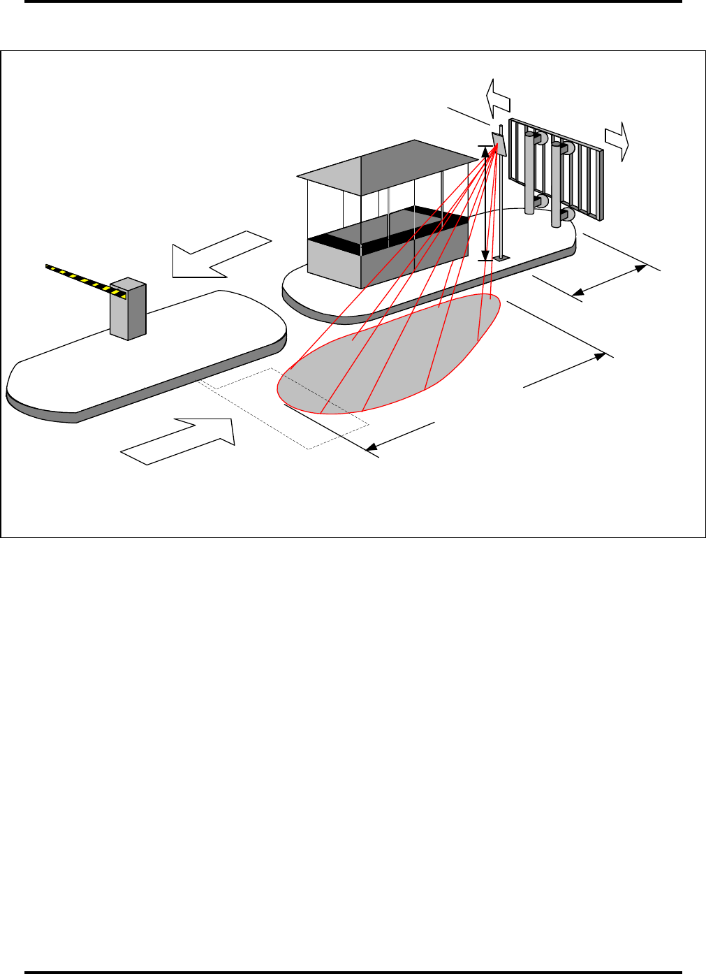
vehicle passes over a Figure 1.1 – System Operation
RADIO FREQUENCY
SIGNAL PATTERN
COVERAGE AREA
ANTENNA MOUNTING HARDWARE
IDentity Flex ANTENNA
SYSTEM SIGNAL
FROM ANTENNA TO VEHICLE
TRANSPONDER ID SIGNAL
FROM VEHICLE TO SYSTEM
HOW THE SYSTEM COMMUNICATES WITH THE TRANSPONDER TAG
Figure 1.1
R E A D Z O N E
15 FEET
MAXIMUM
* See Note
Below
* Note : For additional antenna heights please contact SIRIT - read distances are dependent
upon antenna cable losses

IDentity Flex Hardware Manual - System Overview sirit
Version 2.3 Page 3
detector loop at an entrance or exit, the IDentity Flex reader is armed and begins
to transmit a signal from the antenna in that lane. The vehicle is also now
positioned within the radio beam radiating from an overhead or side-mounted
antenna and the tag receives the wake-up signal.
The tag then reflects back a signal containing its identification number. The
identification signal is received and sent to the host computer for validation and is
compared with tag numbers on a master list kept by the host. If the tag number is
valid, the host opens the gate, for instance.
The same events take place when a vehicle leaves the controlled-access
location and arming and detector loops in the ground may be used as controls.
The host computer maintains an event log containing date and time stamps.
Stand Alone Operation
The IDentity Flex reader is capable of servicing four separate antenna locations.
Each of the four locations are supported by two independent discrete TTL
capable inputs, which may be used for such purposes as vehicle detecting loops
or light curtains. Additionally, each location is also supported by two discrete
outputs which are jumper configurable for either +5VDC or +12 VDC current
limited outputs. These outputs can be used for such purposes as gate vending
control or vehicle stop-and-go light control. Utilizing the ID Flex Windows
software, the reader can be configured for stand alone operation.
Components
IDENTITY FLEX TRANSPONDER FAMILY
The transponders in the IDentity Flex family are small reflective devices designed
for vehicle identification. Each transponder is a battery-operated backscatter
reflective device that communicates the account information stored in an internal
data register of 64 bits when “polled” by the reader system. The transponder is
idle unless in the presence of an RF wake-up signal from a reader on 916.25
MHz.
The IDentity Flex transponder’s wireless link uses comprehensive error detection
methods to ensure a 99.995% accuracy rate even under the most adverse
environmental conditions. Error detection and correction also ensures
information is transferred accurately between the transponder and reader.
The IDentity Flex reader system can communicate with either SIRIT’s IDentity
Flex family of transponders that utilize a Double Phase-Shift Keyed modulation
scheme or CALTRANS (Title 21) readable transponders that utilize a frequency-
shift keyed up-link modulation scheme.

IDentity Flex Hardware Manual - System Overview sirit
Version 2.3 Page 4
IDentity Flex transponders mounted in vehicles are placed at the top of the front
windshield, behind the rear view mirror. The external mount transponder is
attached to the front license plate of the vehicle. See the section starting on
page 52 for mounting instructions.
IDentity Flex Transponder
The IDentity Flex transponder is equipped with a replaceable 4-year coin cell
battery and a second battery can be added for longer life. The transponder is
attached to the windshield by Velcro™ strips. This allows it to be removed from
the vehicle or locked in a glove box while not in use. The IDentity Flex
transponder is pre-programmed at the factory with a dealer code, facility code, ID
number and manufactured serial number.
Security-Flex (S-Flex) Transponder
The S-Flex transponder is equipped with a 4-year non-replaceable battery and is
attached to the windshield with adhesive strips. The transponder will be
deactivated if it is removed after installation, preventing use in unauthorized
vehicles. Deactivated transponders must be returned to SIRIT for reactivation.
Like the IDentity Flex transponder, the S-Flex is pre-programmed at the factory.
External Mount Transponder
An external mount transponder is preferred in truck fleet monitoring applications
and on certain vehicles that have high metal-oxide content in their windshields.
This transponder is mounted on the front license plate holder. More information
on metal-oxide’s effect on Radio-Frequency devices such as the IDentity Flex
transponders can be found on page 51.
External mount transponders can be read by Title 21 systems and, as such, are
programmed for use with the IDentity Flex system on-site by the dealer.
Mounting instructions can be found on page 53.
IDentity Title 21 (Tolling Application) Transponder
The IDentity Title 21 (T21) transponder can be read by highway toll collection
systems that are compliant with the California Department of Transportation’s
Title 21 open standard. It therefore serves a dual-purpose role in also allowing
access to IDentity Flex system controlled areas. It is mounted inside the
windshield with Velcro™ strips. The Title 21 identification number can be loaded

IDentity Flex Hardware Manual - System Overview sirit
Version 2.3 Page 5
into the reader look-up table to allow access to facilities utilizing the IDentity Flex
reader.
IDENTITY FLEX READER
SIRIT’s IDentity Flex reader system is a Radio Frequency Identification (RFID)
system that communicates with California Transportation System Title 21
compliant transponders and SIRIT’s IDentity Flex transponder family.
The IDentity Flex reader is mounted within a weather-resistant NEMA 4X rated
enclosure and is comprised of an RF transceiver and a universal input voltage
power supply. Normally the reader and power supply are mounted onto a
supplied backplane which is sized for the locking NEMA enclosure and provides
a tidy tamperproof installation. A 120 VAC 15 Ampere power source is required
and is adequate to operate one transceiver chassis and power supply.
.
Each reader system is capable of servicing up to four separate transponder-
reading locations (read points). Each of the four read points is supported by two
independent discrete TTL capable inputs, which may be used for such purposes
as vehicle detecting loops or light curtains. Additionally, each transponder
reading location is also supported by two discrete outputs which are jumper
configurable for either +5VDC or +12VDC current limited outputs, which may be
used for such purposes as gate vending control or vehicle stop and go light
control. Each of the four read points may be remotely located from the reader by
up to 200’ of coaxial cable, which connects the reader to the remote antennas.
The reader system may be configured for customized operation by a combination
of externally accessible hardware jumpers and menu driven software settings via
the dedicated RS-232 maintenance communication port. Instructions for
configuring these settings start on page 34. The reader is connected to a laptop
computer running an emulation program such as SIRIT’s Identity Flex Windows
software, ProComm™ or Windows® HyperTerminal™ to perform system setups,
configurations and maintenance functions. The maintenance port also functions
as an input for the purpose of updating the tag translation list.
The IDentity Flex system is capable of communicating transponder transaction
activity to a variety of established back-end host systems, as well as simply
reporting transponder identification to the Host. Additionally, each of the four
different transponder reading channels have their own independent Wiegand
protocol output for reporting to back-end systems. The IDentity Flex reader is
compliant with FCC Part 15 and FCC Part 90 rules.
It is important to establish power requirements and location of the IDentity Flex
reader in conjunction with the Pre-Installation Questionnaire. A guide to
establishing the layout of the system begins on page 9. IDentity Flex reader
installation instructions begin on page 26.

IDentity Flex Hardware Manual - System Overview sirit
Version 2.3 Page 6
IDENTITY FLEX REMOTE ANTENNA
The IDentity Flex remote antenna is an all-weather dual-aperture (transmit and
receive) antenna with an LED feature that permits quick lane configuration. The
LED feature is described below. The antenna measures 30” x 12” x 2” and
comes in a flat gray finish, and can be repainted with non-metallic paint.
The location and angle of the antenna define its read zone and it is essential that
it be installed in the correct orientation and location. The antenna comes with the
Universal Mounting Bracket (UMB) and hardware. Optional brackets may be
ordered so it can be side-mounted on a pole or wall or ceiling-mounted in any
arrangement. A description of these brackets can be found in the next section,
and installation instructions begin on page 20.
It is important to establish the remote antenna location and mounting method in
conjunction with the Pre-Installation Questionnaire. Refer to page 10 for a guide
to lane configuration and antenna location.
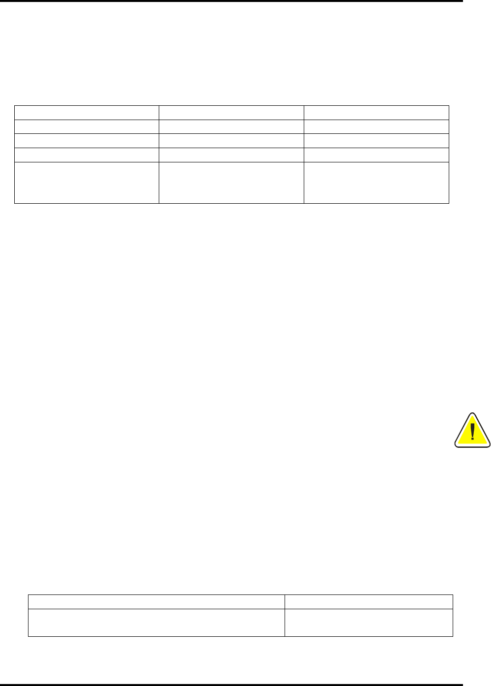
Antenna LED’s – Tag Read Indicator
SIRIT antennas are equipped with an LED indicator which is normally located at
the bottom right-hand corner of the antenna. This LED is used as an indicator
and test tool for the installer and facility staff. When any SIRIT tag enters the
read zone the LED will illuminate. Once the tag has been removed from the
antenna field the LED will extinguish.
This feature will assist the installer in setting the desired read pattern and signal
strength. In addition, if system problems are encountered (e.g. the gate does not
open) this option will help the troubleshooter. If the LED illuminates then the
IDentity Flex reader has read the tag and the cause of this fault is in the tag list
control or back end system. If the LED does not illuminate then there could be a
problem with the reader/antenna system, the tag or something that is restricting
the read such as metal-oxide in the windshield.
For earlier model Flex systems that require an external LED driver, Sirit can
provide a retrofit kit to allow the addition of an external LED indicator which may
be located at the antenna or else where in the lane. For installation of this option
SIRIT recommends that the installer run a separate wire to each antenna of 2
conductor 18 AWG cable.
Remote Antenna Mounting Brackets
This section is designed to familiarize the dealer with options for mounting the
remote antenna that will ensure an acceptable read zone for each installation.
The following catalog of mounting brackets will assist the dealer in completing
IDentity Flex Hardware Manual - System Overview sirit
Version 2.3 Page 7
the Pre-Installation Questionnaire and determining which installation method will
be used for each lane.
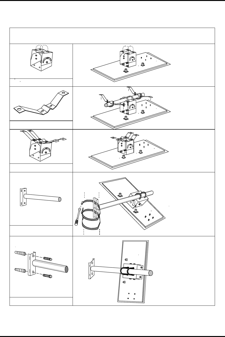
Figure 1.2 – IDentity Flex Mounting Options
IDentity Flex ANTENNA MOUNTING OPTIONS
(See Option Sheet for actual parts that are included)
IDFLEX-ANT-CMB
IDFLEX-ANT-01
ANTENNA
WITH
UNIVERSAL
MOUNTING
BRACKET
(AS SOLD)
UNIVERSAL
CEILING
MOUNT
BRACKET
IDFLEX-ANT-CMB+WMB
UNIVERSAL
POLE / WALL
MOUNT
BRACKET
OPTIONAL
CEILING
MOUNT
METHOD
IDFLEX-ANT-WMB
LAG SCREWS
(Not Supplied)
LAG SHIELDS
(Not Supplied)
IDFLEX-ANT-WMB
OPTIONAL
UNIVERSAL
POLE / WALL
MOUNT
BRACKET
MAN-IDFLEX-FIG7A
SCREWLOK
PIPE CLAMPS
(Not Supplied)
MOUNTING BAR
(Not Supplied)

IDentity Flex Hardware Manual - System Overview sirit
Version 2.3 Page 8
Coaxial Cables and Conduit
Communication between the IDentity Flex reader and the remote antennas is by
means of coaxial cable. There are two cables from each antenna to the reader –
one for the transmit signal, one for the receive signal. Conduit diameter must be
sufficient to house both cables and any other communication cabling required at
the read location. Power cables should not be housed in the same conduit as
these cables.
Cable selection is dependent on the distance between the reader and the remote
antennas. It is important to establish the cabling requirements in conjunction with
the Pre-Installation Questionnaire. See the Site Planning Guide section on
cabling starting on page 17.
Below is a summary of important installation tips:
• If the cable run between the reader and the remote antenna is less
than 50 feet, use Belden 8240 (RG-58/U) cable.
• If the cable run between the reader and the remote antenna is more
than 50 feet (to a maximum of 200 feet) use Belden 9913 cable.
• For Belden 8240 (RG-58/U) cable, installers will need to provide
connectors. SIRIT can provide these by quoting part # IDFLEX-
CONN-RG-58/U. Each kit contains enough connectors to install one
antenna - two (2) Amphenol 82-5375’s and two (2) AMP 226600-1’s.
• A pre-connectorized cable kit is also available from Sirit, Order PN
IDFLEX-CONN RG58/U-60K. Each kit contains 2 – 50’ lengths of
RG58/U cable with “N” connectors installed and 2 crimp mini-uhf
connectors not attached.
• For Belden 9913 cable, installers will need to convert from 9913 to a
mini UHF connector at the reader end. SIRIT can provide a cable
converter kit as an option by quoting part # IDFLEX-CABLECON.
Each kit contains enough connectors for one antenna.
• For Belden 9913 cable, installers will need to provide connectors.
SIRIT can provide these by quoting part # IDFLEX-CONN-9913. Each
kit contains enough connectors to install one antenna - four (4)
Amphenol 82-202-1006 connectors.
• Installers must use the proper crimping tool to install the above
connectors. You can purchase this item locally (Amphenol CTL-5) or
SIRIT can provide this as an option by quoting part # IDFLEX-CRIMP.
• SIRIT recommends that outside connectors be weather-proofed by
applying proper weather-proofing tape. First, mastic tape is applied
over the dry connector then covered with electrical tape. Tape kits are
available from SIRIT by quoting part number IDFLEX-CONN-WKIT.

IDentity Flex Hardware Manual – Site Planning sirit
Version 2.3 Page 9
2.
2.2.
2.
Site Planning
Site PlanningSite Planning
Site Planning
Pre-Installation Questionnaire
The Pre-Installation Questionnaire provided by SIRIT is an essential tool in
determining the site layout and equipment needs.
This guide has been designed to assist the planner make decisions about lane
configurations. If any questions arise regarding the location of vehicle presence
loops, gates and remote antennas, the answers should be in the following
section.
If there are questions about cabling and connectors, the Installation Tips sheet
on the front of the questionnaire should cover them, and a further description can
be found in the section starting on page 17.
SIRIT Pre-site Assistance
As an added service SIRIT offers pre-site assistance to our resellers. Upon
receipt of a purchase order for an IDentity Flex System, SIRIT will send a fax or
email which:
1) Confirms the order;
2) Requests transponder facility code and identification information (if
transponders have been ordered) and
3) Requests completion of our pre-site questionnaire. SIRIT takes pride in
assisting our resellers by reviewing and making recommendations on pre-
site requirements.
If you have not received your confirmation fax with the above information please
contact SIRIT.

IDentity Flex Hardware Manual – Site Planning sirit
Version 2.3 Page 10
Lane Logic Considerations
The following sections contain guidelines for establishing lane configurations, first
for Parking Access, then additional considerations for Gated Access starting on
page 12.
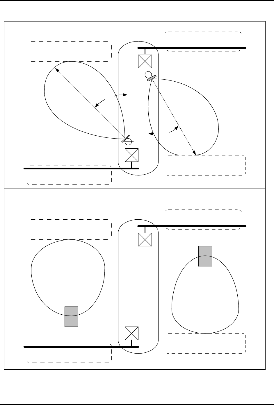
PARKING ACCESS SYSTEMS
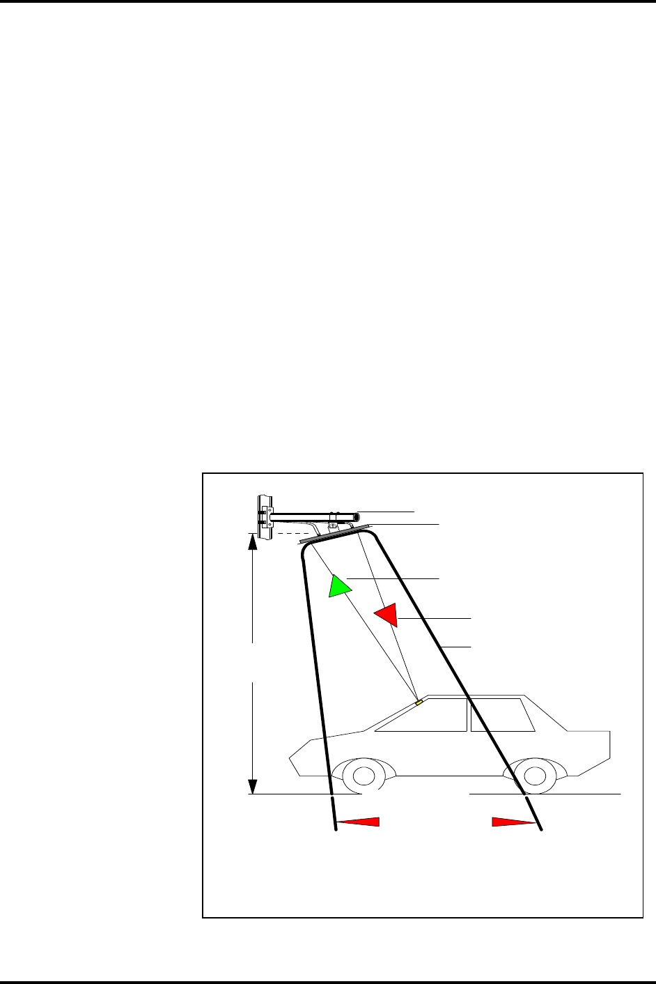
Antenna Mounting – Read Zone
The Read Zone is a roughly conical space between the antenna and the elliptical
area on the ground that the signal illuminates. Once the transponder is in the
read zone, it reflects a signal back to the antenna. The shape of the read pattern
is dependent on the location of the antenna, its orientation on the mounting
bracket and the power output of the reader. The installer should use the
following guidelines to ensure that:
• Transponders in adjacent lanes are not read
• Vehicles are not trapped between the read zone and the gate
• Vehicles slow to an appropriate speed (or stop) before the gate opens.
Lane presence inductive loops are typically embedded 8-10 feet from the gate
and the read zone should start just past this loop moving towards the gate.
For Parking Access Systems, SIRIT recommends that the antenna pole or
overhead antenna be mounted approximately 2 – 3 feet in front of the gate. This
will ensure that the antenna read pattern will be at approximately 10 feet from the
gate and in close proximity to the presence loop. Once the antenna is aimed
(approximately 40° angle from vertical) the antenna pattern will be within this 10-
foot range.
Antennas are typically mounted on poles or ceilings at 10 –15 feet in height.
Angling the antenna down so that the beam is in the desired location ensures
proper reading of tags. The antenna can be physically adjusted and the power
settings set in the reader software to obtain the desired results. Setting the
power level too high may result in reflection of the beam and the possibility that
adjacent lanes will be read. Setting the power level too low may result in no or
intermittent tag reads.
The following diagram gives an example of a typical installation. These figures
are examples only and should not be utilized as an installation guide. For further
assistance, please contact a SIRIT representative.
IDentity Flex Hardware Manual – Site Planning sirit
Version 2.3 Page 11
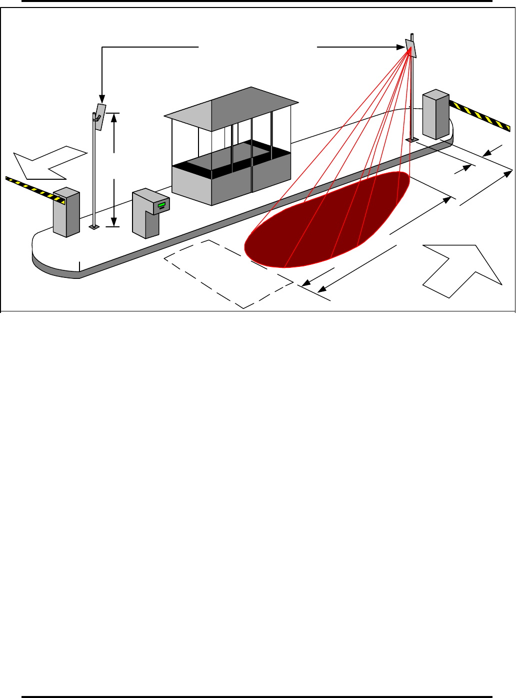
Figure 2.1 – Typical Parking Access Lane Configuration
Memory Gates
Memory gates are typically used if the SIRIT antenna read zone will be
positioned more than 10 feet from the gate or where there is a possibility that a
vehicle may get stuck between the presence loop and the gate and not be in the
read zone. Memory gates are used to buffer the gate open signal for the second
or third car in the lane depending upon how far back the read pattern is. The
further away the antenna read range, the more signals the gate will have to
buffer. If antennas are too far back in the lane, there is a possibility that a lane
logic issue will result, if an invalid vehicle enters the lane along with valid
vehicles.
Internal Buffer Circuit
SIRIT has an internal buffer circuit that can be used only when the IDentity Flex
reader controls the gate directly. It operates in the same fashion as memory
gates as stated above by buffering the gate open signal. The IDentity Flex
reader must receive a change of state of a gate position signal to clear the buffer
or pass the next gate open signal.
IDentity Flex Antennas
EXIT
POLE HEIGHT
10 - 15 FEET
2 - 3 FEET
ARMING / ENTRY LOOP
8 -10 FEET
READ ZONE
ENTRY
EXAMPLE OF A LANE LAYOUT FOR PARKING ACCESS SYSTEMS
DWG-IDFLEX-KIOSK-01A

IDentity Flex Hardware Manual – Site Planning sirit
Version 2.3 Page 12
Arming the SIRIT IDentity Flex Antenna
Under certain conditions it is desirable to arm the SIRIT IDentity Flex antenna on
demand. This can be accomplished by using the dry contact output from the
Gate Down position switch, presence loop dry contact output or both. For
example the location may have a situation where users remove the IDentity Flex
transponder from the vehicle and walk past the antenna. If anti-passback is
activated then the users’ vehicle may be locked in. In this situation it is desirable
to only read the transponder when the vehicle is over the presence loop. The
presence loop would be used to arm the antenna. Arming the antenna also
ensures that there is no risk of unwanted reads if a vehicle comes close to an
antenna but is not on the presence loop.
The site may not have memory gates and this means that the AVI signal should
not be sent to the host until the gate starts in the Down position. If the AVI signal
is sent while the gate is in the Up position it will be lost. At the same time it is
desirable to read the transponder while the vehicle is over the presence loop. To
accomplish this the dry contacts of the Gate Down position switch and the loop
output dry contacts can be connected in series. When both conditions are met,
with the vehicle over the loop and the gate arm starting to come down, the
antenna will be armed and the transponder will be read. In this scenario it is
desirable to have the antenna read pattern within 10 feet of the gate (antenna
pole mounted at 2-3 feet from the gate). This avoids having the vehicle stuck in
the lane due to a lane logic issue.
GATED ACCESS SYSTEMS
Gated Access systems maybe different from Parking Access as the traffic flow
and overall requirements differ. In Parking Access there are revenue control
considerations and a requirement to open the gate when the vehicle is close to
the gate. This may or may not be the same in Gated Access systems.
Figure 2.2 shows typical Gated Access lane configurations. These figures are
examples only and should not be utilized as an installation guide. For further
assistance, please contact a SIRIT representative.
IDentity Flex Hardware Manual – Site Planning sirit
Version 2.3 Page 13
Figure 2.2 – Typical Gated Access Lane Configurations
In addition to the In addition considerations for Parking Access, the Gated
Access system installer may include the following options in the installation plan.
Use of Entry Presence Loops
Entry presence loops can be utilized to arm the SIRIT reader. Depending on the
application, presence loops may or may not be required.
Figure 2.2 shows a typical configuration with an arming loop. For more
information, please contact your dealer or Sirit.
IDentity Flex Antenna
READ ZONE
DISTANCE IS SITE
SPECIFIC
ENTRY
FREE EXIT
EXAMPLE OF A LANE LAYOUT FOR GATED COMMUNITY SYSTEMS
DW G -ID FLEX -KIO SK-03A
POLE HEIG HT
5 - 15 FEET
SLIDING GATE
Entry Arming Loop

IDentity Flex Hardware Manual – Site Planning sirit
Version 2.3 Page 14
Use of S-Flex Transponder
Gated Access systems may have a requirement for SIRIT’s Break on Removal
(BOR) S-Flex transponder. The main difference between the S-Flex transponder
and the standard IDentity Flex transponder is that the S-Flex transponder will
deactivate once it is removed from the windshield. In addition, users should be
made aware of proper test procedures for testing for metal-oxide
windshields prior to permanently affixing the S-Flex transponder to the
windshield. These procedures can be found on page 51.
Gate Output Relays
Gated Access systems may require that SIRIT activate the gate directly from the
SIRIT IDentity Flex reader. SIRIT makes relays and mounting components
available as an option.
Memory Gates
Memory gates or the use of SIRIT’s reader buffer circuit (If the IDentity Flex
reader controls the gate directly) may be required. This will be a requirement if
the antenna and read zone are further away from the gate (beyond 10’ as in
Parking Access systems). The read zone could be, for example, up to 50 feet
away. However, this may create unwanted access due to an unauthorized
vehicle getting stuck between two authorized vehicles.
If a facility wishes to place the antenna read pattern beyond 10 feet there may
not be a concern with unwanted access. Placing the antenna read distance far
away allows time for the gate to open so vehicles do not have to slow down and
this may be desirable. At some entry points, booths may be manned and this
reduces the risk of any lane logic issues.
Use of T21 (Tolling Application) Transponders
Gated Access systems can accommodate users who have SIRIT’s T21 tolling
application transponders. The T21 transponder serial numbers will have to be
converted and entered into each reader’s database to output the desired facility
code and ID.
Desktop Reader
In certain situations, Gated Access sites may have a large number of T21
transponders to enter into the reader’s database. To make this task easier SIRIT

IDentity Flex Hardware Manual – Site Planning sirit
Version 2.3 Page 15
makes available an optional desktop reader which allows each tag to be scanned
into the database. Users can scan in the source tag Identification number and
then assign a destination or output identification number containing a facility code
and ID. Each IDentity Flex reader is capable of storing up to 10,000 translated
T21 transponders in its database.
Antenna Mounting
Gated Access systems may require that the SIRIT antenna be mounted lower in
height compared to Parking Access systems. In order to ensure consistent reads
SIRIT recommends that the antenna be mounted at 10-15 feet above the island.
Please consult with SIRIT if lower antenna heights are desirable.
Installers of Gated Access systems should also review lane logic considerations
for Parking Access systems as some of the sections (e.g. Antenna LED’s – Tag
read indicator and SIRIT Pre-site assistance) will also apply.
MULTIPLE READER INSTALLATIONS
Multiple Local or Remote Readers
Gated Access systems may have multiple local or multiple remote readers. If
configurations or tag databases need to be updated SIRIT has a number of
options available. SIRIT can support up to 60 local readers through optional
smart switches. Local readers can be connected up to 4 miles away with the use
of optional short haul modems. If access is required to readers that are located
beyond the 4-mile limit SIRIT makes available dial-up capabilities using optional
US Robotics® 56K external modems. Multiple local or remote reader access
requires the use of SIRIT’s Windows®-based IDentity Flex software.
Instructions for configuring the IDentity Flex system for multiple readers can be
found on page 41. Additional information can be found in the Windows®-based
IDentity Flex software manual.
Remote Antenna Mounting
REMOTE ANTENNA MOUNTING OPTIONS
Overhead
For overhead installations, antenna brackets are bolted to ceilings at a height of
no more than 15 feet above the driveway. Antennas brackets are adjusted to

IDentity Flex Hardware Manual – Site Planning sirit
Version 2.3 Page 16
produce an antenna angle of between 5 to 45 degrees from horizontal, tilted
towards oncoming traffic. Should there be an obstruction in the lane center such
as a lamp or conduits, adjustment of the UMB will allow an additional sideways
tilt of up to 45 degrees to compensate for the offset from lane center. Consider
adding vehicle clearance signs to prevent damage to the antennas from oversize
vehicles. It is important that any reflective surfaces such as metal signs or metal
height restriction bars are not placed in the antenna’s read zone.
Side-Mounting
IDentity Flex antennas may be mounted on vertical poles or horizontal pipes
utilizing the supplied UMB or CWB. Note that each antenna requires two (2)
coaxial cable feeds, one being Transmit, the other Receive. Cables may be
clamped to walls with clips or run through appropriate conduits.
Equipment Placement and Cable Routing
READER LOCATION
Many factors can determine the location of the IDentity Flex reader in an
installation.
There are two primary requirements:
• The reader must be accessible for maintenance purposes;
• There must be a source of AC power for the reader.
Secondary considerations include:
• The reader may need to be in a secure area such as inside a toll kiosk or
gatehouse;
• Locating the reader in close proximity to the host system interface results in
a single maintenance location;
• It may be more cost-effective to have the reader as close as possible to the
antenna locations since runs of coaxial cable and I/O wiring are more
expensive per foot than the Wiegand interface cable to the host systems;
• The reader must be within a cable-run distance of 200 feet from the furthest
antenna;
• Cost will be minimized by having a centrally-located reader with respect to
the remote antenna locations;
• Although mounted in a robust NEMA 4X enclosure, readers should be
placed in a location that will not unnecessarily expose them to harsh
operating or climatic conditions such as extreme heat or cold, salt splashes
and corrosive chemicals.
Once a decision is made on the location for the IDentity Flex reader, the installer
can move on to cable selection.

IDentity Flex Hardware Manual – Site Planning sirit
Version 2.3 Page 17
REMOTE ANTENNA CABLE AND CONDUIT SELECTION
Antenna Cable Selection
If the cable run between the reader and the remote antenna is less than 50 feet
use Belden 8240, RG-58/U cable.
If the cable run between the reader and the remote antenna is more than 50 feet,
to a maximum of 200 feet, use Belden 9913 cable.
Remote antenna coaxial leads require cable connectors at each end and each is
different. Refer to Table 2.1 and Table 2.2 below for selection of the coaxial
cables and connectors required.
Table 2.1 – Remote Antenna Cable Selection
Distance, Reader
to Antenna
Recommended
Cable Type
Cable Diameter
Inches/mm
Attenuation
per 50 Feet of
Cable, dB
0 – 50 Feet Belden 8240,
RG-58/U
0.195/4.95 7.25 dB
50 – 200 Feet Belden 9913 0.404/10.29 2.25 dB
Conduit Selection
Antenna coaxial cable runs can be fastened in place with clips, but it is
recommended that all cable be housed in conduit to protect the wiring from
adverse weather, property maintenance tools and, to some degree,
electromagnetic interference (EMI).
Communication and antenna cabling can share the same conduit but it is
recommended that a separate conduit be used for AC power if required.
Ensure conduit diameter is sufficient to house at least two cables per antenna.
For example, two Belden 9913 cables with OD 0.404” require 0.808” of diameter,
or 1” conduit. If ¾” conduit were selected for RG-58/U cabling and later
circumstances required a change to Belden 9913, two 9913’s would not fit inside
the ¾” conduit. When making conduit size selection, allow for shielded twisted
pair wires for each input and output circuit at each read point because there may
be up to two circuits for each channel. If a site will be installed without the LED
Tag Read Indicator antennas, and a retrofit may be desired later, increase
conduit size to accommodate the 2 conductor 18 AWG cable.
IDentity Flex Hardware Manual – Site Planning sirit
Version 2.3 Page 18
REMOTE ANTENNA CABLE CONNECTORS
Use the following table to determine which precision UHF coaxial connectors are
required for the installation. All cable ends require connectors.
Table 2.2 – Antenna/Reader Connector Selection
Where Used Cable Type Manufacturer Number
Antenna Connector RG-58/U Amphenol 82-5375
Reader Connector RG-58/U AMP 226600-1
Antenna Connector 9913 Amphenol 82-202-1006
Reader Connector
(Adapting cable jumper)
9913 - See Figure 3.10
on page 33
(CABLECON is RG-58/U)
Amphenol 82-202-1006
and “CABLECON”
adapter
For Belden 8240 (RG-58/U) cable, installers will need to provide connectors.
SIRIT can provide these by quoting part # IDFLEX-CONN-RG-58/U. Each kit
contains enough connectors to install one antenna (two (2) Amphenol 82-5375
and two (2) AMP 226600-1).
For Belden 9913 cable, installers will need to provide connectors. SIRIT can
provide these by quoting part # IDFLEX-CONN-9913. Each kit contains enough
connectors to install one antenna (four (4) Amphenol 82-202-1006 connectors).
For Belden 9913 cable installers will need to convert from 9913 to a mini-UHF
connector at the reader end. An 18” adapter cable is used to adapt the N Type
connector on the 9913 cable to the reader’s Mini-UHF input. See Figure 3.10 on
page 33 for adapter options. SIRIT can provide cable converter kit as an option
by quoting part # IDFLEX-CABLECON.
Installers must use the proper crimping tool to install the above
connectors. Installers can purchase this item locally (Amphenol CTL-5) or
SIRIT can provide this as an option by quoting part # IDFLEX-CRIMP. Sirit
recommends that outside connectors be weatherproofed by applying
proper weather-proof tape. First, mastic tape is applied to the dry connector,
then covered with electrical tape. Tape kits are available from Sirit by quoting
part number IDFLEX-CONN-WKIT.
Cable Kits
The following Table 2.3 provides a list of pre-made cables available from Sirit:
Table 2.3 – Cable Kit
Description Manufacturer Number
2 ea 50’ RG-58/U Cable, N connector
attached, 2 mini UHF Connector assembly
IDFLEX-CABLE-RG58/U-60K

IDentity Flex Hardware Manual – Site Planning sirit
Version 2.3 Page 19
AC POWER CONNECTIONS
The reader accepts 85 to 265 VAC 47-440 Hz input power. Line, neutral and
safety ground connections are provided via the included power cord with 120
VAC three-prong plug. Check with local authorities for any additional local
regulations.
When a customer orders a unit wired for 240 VAC power, it is supplied with a
standard 120 VAC three-prong plug. If an alternative plug is required, the
customers will be required to provide their own power plug.
Use the correct wire and appropriate power and ground connections for all
connections in accordance with the local electrical regulations.
List of Materials
HARDWARE INSTALLATION TOOLS
Hardware installation will require the following tools:
• Standard hand tools
• Adjustable wrenches
• Wire stripper
• Crimping tool as per connector manufacturer’s guidelines
• Digital multimeter
• Soldering tools
INTERFACE / DIAGNOSTIC TOOLS
Software and configuration setup will require the following:
• Laptop computer or PC running ProComm™, Windows® HyperTerminal™
or Sirit IDentity Flex Windows software.
• Serial cable (Pin-to-Pin) with DB-9 male connector for connection to the
reader. DO NOT USE A NULL MODEM CABLE!
• IDentity Flex Antenna part # IDFLEX-ANT-01
• IDentity Flex Reader – 2-Channel or 4-Channel
• Quantity 2 – 10 feet RG-58/U test cables with connectors
IDentity Flex Hardware Manual – Installation sirit
Version 2.3 Page 20
3.
3.3.
3.
Installation
InstallationInstallation
Installation
Installation typically follows this sequence:
• Remote Antenna Installation
• Reader Installation
• Quick Power-On Test
• Antenna Lead Installation
• Cable Connector Installation
• Interface Connections
• Transponder Usage
The following sections detail the procedures for completing the installations.
Remote Antenna Installation
Remote antenna locations will have been decided during the Pre-Installation
process. A description of this process begins on page 10. Refer to Figure 3.1,
3.2 and 3.3 for antenna orientation positions.
Figure 3.1 – Antenna Orientation
IDentity Flex
by SIRIT
DWG-IDFLEX-ANT-ORIENT-01
TOP
BOTTOM
FRONT BACK
Read indicator
Transmit
Receive

IDentity Flex Hardware Manual – Installation sirit
Version 2.3 Page 21
Note that the front of the antenna is the flat side with the SIRIT logo. The rear of
the antenna contains the cable connectors and mounting bracket studs. The
bottom of the antenna is the end closest to the end-located mounting studs. See
page 24. Do not drill any holes in the antenna assembly. Drilling holes will
internally damage the antenna rendering it inoperable.
The orientation of the antenna is shown in Figure 3.1, with the IDentity by Sirit
logo easily readable in the bottom left-hand corner. Antennas should be installed
to position the radiated beam centered in the lane. The center of the antenna
should be 10-15 feet above the ground. Ensure that no metal is placed in front of
the antenna in its final adjusted position.
Antennas may be affixed to the ceiling, to poles, pipes or conduits with SIRIT’s
Universal Antenna Mounting (UMB) bracket and cables dressed to poles or
pipes. See Figure 1.2 on page 7 and Figure 3.3 on page 23 for some
recommended mounting options.
Shielded signal or communications cables such as low voltage may be run
through the same conduit as the antenna leads where allowed by law. Power
cables such as high voltage should not be run through the same conduit as the
antenna leads.
Figure 3.4 on page 24 details the connections for the antenna and cables.
NOTE: Readers with S/N greater than 321 have the LED signal incorporated
into the receive line. To ensure the proper functionality of the LED it is
necessary to ensure the transmit and receive cables from the reader are
connected to the corresponding connector on the back of the antenna. The
connectors are labeled on the back of the antenna to assist in proper connection.
IDentity Flex Hardware Manual – Installation sirit
Version 2.3 Page 22
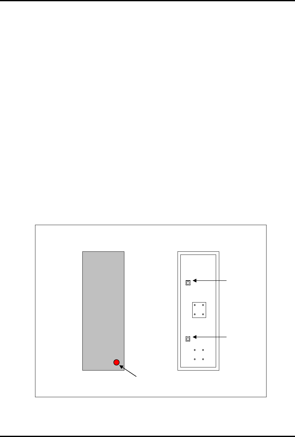
Figure 3.2 – Antenna Mounting Angles
5 - 30
CEILING MOUNT ADJUSTMENTS
DWG-IDFLEX-ANT-CEILING-01
SIGNAL
BEAMWIDTH
TRAFFIC
ISLAND
LANE
ANGLE
"B"
ANGLE
"C"
ELEVATION ANGLE "A" IS ADJUSTED BY TURNING
U-BOLTS ON POLE-MOUNT PIPE UP TO 30 DEGREES.
AZIMUTH ANGLE "B" CAN BE ADJUSTED UP TO 30
DEGREES INTO THE LANE. ANGLE "C" CAN BE
ADJUSTED UP TO 30 DEGREES.
LANE
ISLAND
CEILING
OBSTRUCTION
ANTENNA CENTERED OVER LANE
OFFSET ANTENNA
ANTENNA POLE
CLOSE TO CURB
ANTENNA POLE LOCATED IN CENTER
OF ISLAND
SIGNAL
BEAMWIDTH
TRAFFIC
SIGNAL
BEAMWIDTH
SIGNAL
BEAMWIDTH
POLE MOUNT ADJUSTMENTS
ANGLE "A"
5 - 30
IDentity Flex
by Sirit
IDentity Flex
by Sirit
IDentity Flex Hardware Manual – Installation sirit
Version 2.3 Page 23
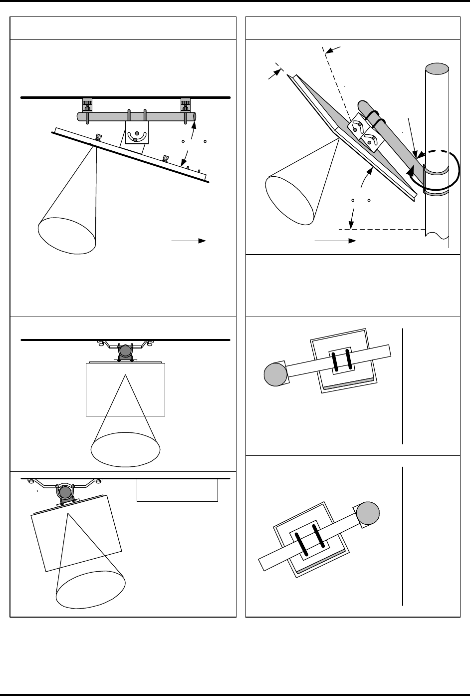
Figure 3.3 - Antenna Lateral Orientation
READ ZONE
VEHICLE PRESENCE LOOP
GATE RESET LOOP
GATE RESET LOOP
READ ZONE
READ ZONE
VEHICLE PRESENCE LOOP
GATE RESET LOOP
VEHICLE PRESENCE LOOP
READ ZONE
GATE RESET LOOP
OUTSIDE POLE- MOUNTED
INDOOR CEILING - MOUNTED
VEHICLE PRESENCE LOOP
DWG-IDFLEX-LANELAYOUT-02
*
*
*
SEE FIG. 3.2 FOR ANGLES
IDentity Flex Hardware Manual – Installation sirit
Version 2.3 Page 24
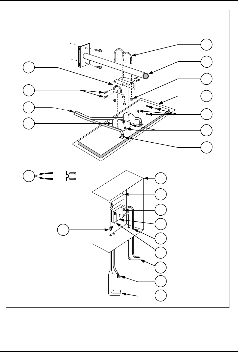
Figure 3.4 – Remote Antenna/Reader Connection Diagram
IDentity Flex HARDWARE INSTALLATION
2.
3.
8.
7.
11.
9.
12.
4.
5.
13.
15.
14.
16.
6.
17.
21.
18.
19.
20.
10.
1.
5.
MAN-IDFLEX-FIG3.1B

IDentity Flex Hardware Manual – Installation sirit
Version 2.3 Page 25
Table 3.1 – Legend for Figure 3.4
Item
No.
Description Supplied by
SIRIT
1 U-Bolts, antenna mounting bracket, 2 per bracket ✓
✓✓
✓
2 WMB, pipe, mast or conduit used for antenna mount
3 UMB Antenna bracket half, conduit mount side ✓
✓✓
✓
4 UMB Antenna bracket half, antenna mount side ✓
✓✓
✓
5 Coaxial cables, 50 Ohm, See Table 2.1 (p. 17)
6 Concrete lag bolts or screws and cable clamps
7 Bracket pinning bolts, 2 required ✓
✓✓
✓
8 Nuts for U-bolts, 4 per bracket ✓
✓✓
✓
9 IDentity Flex antenna assembly, shown facing down ✓
✓✓
✓
10 Bracket mounting nuts, ¼-20, 4 per bracket ✓
✓✓
✓
11 Alternate studs, for various mounting options ✓
✓✓
✓
12 Coaxial Type-N connector, see Table 2.2 (p. 18)
13 NEMA 4X Enclosure or utility waterproof housing ✓
✓✓
✓
14 IDentity Flex power supply ✓
✓✓
✓
15 Coaxial Mini-UHF connector, see Table 2.2 (p. 18)
16 IDentity Flex reader, showing one antenna connected
✓
✓✓
✓
17 Conduit or cable bushing in NEMA box
18 Wiegand or interface lines to controlled circuits
19 Multi-conductor cable fan-out to interfaces
20 AC power line to service panel
21 AC power line terminal strip
IDentity Flex Hardware Manual – Installation sirit
Version 2.3 Page 26
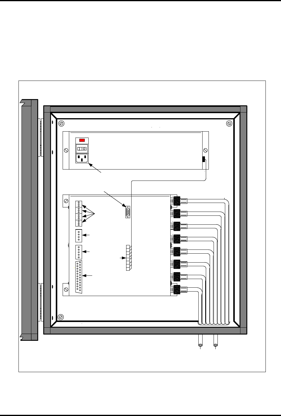
Reader Installation
The reader location will have been determined during the pre-installation process
after consideration of the factors described on page 16. The reader should be
mounted prior to cutting cable lengths to ensure correct measurement. Figure
3.5 following shows the basic cabling arrangement inside the reader.
Figure 3.5 – Reader Connections
RX1
TX1
115
RG-58/U
RX2
RX3
RX4
TX2
TX3
TX4
WIEGAND
OUTPUTS
DC POWER
INPUT
RG-58/U
RG-58/U
RG-58/U
RG-58/U
RG-58/U
RG-58/U
RG-58/U
DC POWER SUPPLY
+/- 12 VDC /+ 5 VDC
RX1 TX1
RX1-TX1 PAIR TO
ANTENNA No.1
P1 MAINTENANCE
INTERFACE "RS-232"
IDENTITY FLEX READER INSTALLATION IN 4X NEMA ENCLOSURE
RECEIVE
ANTENNAS
TRANSMIT
ANTENNAS
AC POWER CONNECTION
SYNC
HOST
DISCRETE I/O
CONNECTOR
A
B
C
D
MAN-IDFLEX-FIG3.2A

IDentity Flex
Hardware Manual – Installation
sirit
Version 2.3 Page 27
Quick Power-On Test
A Quick Power-On Test is used to verify power connections and correct
operation of the reader after shipping.
1) CAUTION: HIGH VOLTAGE PRESENT.
2) Ensure that the reader power switch is in the OFF (O) position
3) Connect a power cable from the receptacle in power supply to AC Outlet.
4) Connect appropriate antennas. If antenna cables are not yet ready,
complete the following section to attach the antenna leads to all enabled
channels. DO NOT ENABLE RF POWER TO A PORT WITH NO
ANTENNA OR DUMMY LOAD CONNECTED.
5) Turn the reader power switch ON (|).
6) The Sync Indicator LED (7) should come ON except if the unit is a slaved
part of a synchronized installation where the master is OFF.
7) The CPU Active LED (8) should flash to indicate CPU operation.
8) Turn the reader power switch OFF (O).
9) Disconnect the power cable from the AC outlet.
Antenna Lead Installation
Coaxial Cable
Antenna leads are the cables that connect the reader with the remote antennas.
Two cables are required for each antenna – one for Transmit and one for
Receive.
If the cable run between the reader and the remote antenna is less than 50 feet
use Belden 8240, RG-58/U cable.
If the cable run between the reader and the remote antenna is more than 50 feet,
to a maximum of 200 feet, use Belden 9913.
Conduit
Install the conduit, if required, between the reader and the remote antenna
locations. In some cases, it may be beneficial to pre-insert the cable before
fastening or burying the conduit.
Ensure conduit diameter is sufficient to house at least two cables per antenna.
For example, two Belden 9913 cables with OD 0.404” require 0.808” of diameter,
or 1” conduit. If ¾” conduit were selected for RG-58/U cabling and later
circumstances required a change to Belden 9913, two 9913’s would not fit inside
the ¾” conduit. When making conduit size selection, allow for shielded twisted

IDentity Flex
Hardware Manual – Installation
sirit
Version 2.3 Page 28
pair wires for each input and output circuit at each read point because there may
be up to two circuits for each channel. If a site will be installed without the LED
Tag Read Indicator antennas, and a retrofit may be desired later, increase
conduit size to accommodate the 18 AWG twisted pair shielded cable.
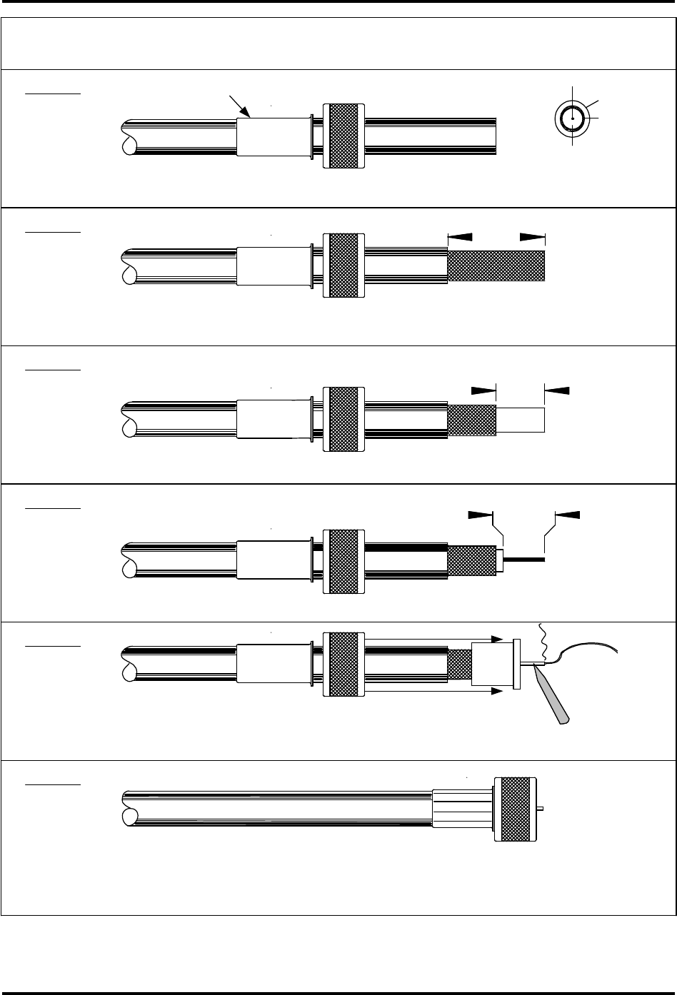
Cable Connector Installation
Precision UHF coaxial connectors are required on all cable ends. Prepare cable
ends exactly as shown in the following pages. Failure to follow exact
dimensioning will considerably degrade system performance. After
assembly, check the cables for short circuits with an ohmmeter and attach the
antenna leads to the readers and antennas as shown in Figure 3.4 on page 24
and Figure 3.5 on page 26.
Installers must use the proper crimping tool to install the following
connectors. You can purchase this item locally (Amphenol CTL-5) or SIRIT can
provide this as an option by quoting part # IDFLEX-CRIMP. Sirit recommends
that outside connectors be weather-proofed by applying mastic tape over
dry connectors then covering with electrical tape. Weather-proofing kit is
available from Sirit by quoting part number IDFLEX-CONN-WKIT.
RG-58/U CABLE
For Belden 8240, RG-58/U cable installers will need to provide connectors. Each
antenna requires (2) Amphenol 82-5375 and (2) AMP 226600-1 or SIRIT can
provide this as an option by quoting part # IDFLEX-CONN-RG-58/U. Figure 3.6 ,
Figure 3.7 and Figure 3.8 detail installation of the connectors for RG-58/U cable
starting on page 29.
BELDEN 9913 CABLE
For Belden 9913 cable installers will need to provide connectors. Each antenna
requires (4) Amphenol 82-202-1006 connectors or SIRIT can provide these as an
option by quoting part # IDFLEX-CONN-9913. Figure 3.9 on page 32 details
installation of the connectors for Belden 9913 cable.
ANTENNA CABLE ADAPTER
For Belden 9913 cable installers will need to convert from 9913 to a mini UHF
connector at the reader end. SIRIT can provide cable converter kit as an option
by quoting part # IDFLEX-CABLECON.
Figure 3.10 on page 33 details assembly
of the Antenna Cable Adapter.
IDentity Flex
Hardware Manual – Installation
sirit
Version 2.3 Page 29
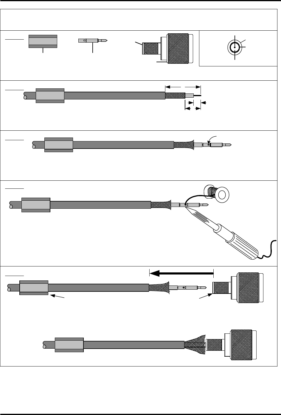
Figure 3.6 – RG-58/U Amp 226600-1 Installation
READER CONNECTOR ASSEMBLY - RG-58/U CABLE
STEP 1.
RG-58/U CABLE
CUT END OF CABLE EVEN AND SLIDE CRIMP FERRULE AND COLLAR ONTO CABLE
STEP 2.
AMP CRIMP TYPE CONNECTOR NO. 226600-1
REMOVE 0.938"/23.83 MM OF VINYL JACKET - DO NOT NICK THE BRAID OF CABLE
STEP 3.
STEP 4.
STEP 5.
STEP 6.
0.938"
23.83 MM
REMOVE 0.641"/16.28 MM OF BRAID - DO NOT KNICK THE INSULATION
REMOVE 0.594"/15.09 MM OF INSULATION - DO NOT KNICK THE CENTER CONDUCTOR
INSERT PLUG ASSEMBLY ONTO CABLE AND CENTER CONDUCTOR. SOLDER THE CENTER
CONTACT PIN BUT DO NOT ALLOW SOLDER TO FLOW ONTO OUTSIDE OF PIN
0.641"
16.28 MM
0.594"
15.09 MM
SLIDE COLLAR AND FERRULE OVER PLUG ASSEMBLY. CRIMP THE FERRULE USING ONLY
0.213" DIESET . CHECK BETWEEN CENTER PIN AND SHIELD WITH OHMMETER TO MAKE
SURE CABLE IS NOT SHORTED. APPLY WATERPROOFING TAPE OVER CRIMPED FERRULE.
VINYL JACKET
BRAID WIRE
DIELECTRIC INSULATION
CENTER CONDUCTOR
DWG-IDFLEX-ANT-CABLE-01
SLIDE CRIMP FERRULE ONTO CABLE FIRST
IDentity Flex
Hardware Manual – Installation
sirit
Version 2.3 Page 30
Figure 3.7 – RG-58U Amphenol 82-5375 Installation (Part A)
ANTENNA CONNECTOR ASSEMBLY - RG-58/U CABLE
AMPHENOL CRIMP/SOLDER-TYPE CONNECTOR NO. 82-5375
A = .531" (13.5 mm)
A
B
C
B = 0.233" (5.9 mm)
C = 0.140" (3.5 mm)
STEP 1.
LAY OUT THE CONNECTOR PARTS FOR IDENTIFICATION. FROM LEFT TO RIGHT - CRIMP FERRULE, CENTER PIN
AND THE CONNECTOR BARREL.
STEP 2.
STRIP CABLE JACKET, BRAID AND DIELECTRIC TO DIMENSIONS SHOWN. CUT SHARP AND SQUARE. DO NOT
NICK BRAID, DIELECTRIC OR CENTER CONDUCTOR. SLIDE CRIMP FERRULE ONTO CABLE AS SHOWN - DO NOT
COMB OUT BRAID.
STEP 3.
SLIGHTLY FLARE END OF CABLE BRAID AS SHOWN TO FACILITATE LATER INSERTION OF
INNER FERRULE. PLACE CONTACT PIN ON CABLE CENTER CONDUCTOR BUTTING AGAINST
DIELECTRIC. CENTER CONDUCTOR SHOULD BE VISIBLE THROUGH INSPECTION HOLE
SOLDER
CONTACT PIN
OUTER CRIMP FERRULE
INNER FERRULE
MAIN BODY
STEP 4.
TIN CENTER CONDUCTOR BEFORE INSERTION INTO CONTACT
PIN. SOLDER CONTACT PIN TO CENTER CONDUCTOR BY
FEEDING SOLDER INTO INSPECTION HOLE AS SHOWN. DO NOT
LEAVE SOLDER ON OUTSIDE OF PIN - SCRAPE OFF WITH KNIFE.
AVOID EXCESSIVE HEAT - 5 SECONDS MAXIMUM TO PREVENT
SWELLING OF DIELECTRIC WHICH WILL NOT FIT THRU BARREL IF
ENLARGED.
STEP 5.
INNER FERRULE
CAREFULLY INSERT CONTACT PIN INTO CONNECTOR BARREL SO INNER
FERRULE SLIDES UNDER CABLE BRAID. PUSH CONNECTOR BARREL FORWARD
UNTIL CONTACT PIN SNAPS INTO PLACE IN INSULATOR.
CENTER CONDUCTOR
VINYL JACKET
BRAID WIRE
DIELECTRIC INSULATION
RG-58/U
CABLE
DWG-IDFLEX-ANT-CABLE-01A
INSPECTION HOLE
OUTER CRIMP FERRULE
IDentity Flex
Hardware Manual – Installation
sirit
Version 2.3 Page 31
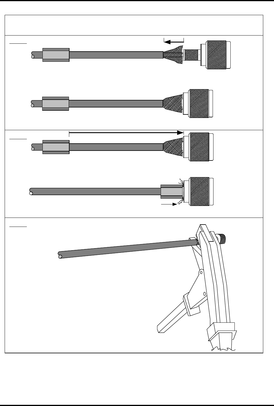
Figure 3.8 - RG-58U Amphenol 82-5375 Installation (Part B)
CABLE CONNECTOR INSTALLATION - RG-58/U CABLE
AMPHENOL CRIMP-TYPE CONNECTOR NO. 82-5375 ON ANTENNA END OF CABLE
STEP 6.
STEP 7.
CONTACT PIN MUST SNAP IN AT SAME TIME AS BRAID BUTTS UP AGAINST CONNECTOR
BODY AS SHOWN BELOW
SLIDE OUTER FERRULE ALONG CABLE AND OVER TOP OF
BRAID AND UP AGAINST THE CONNECTOR BODY.
STEP 8.
USING ONLY THE CORRECT 0.213" DIESET CAVITY
ON THE CRIMPING TOOL, CAREFULLY SQUEEZE
THE TOOL AND CRIMP THE OUTER FERRULE.
CHECK FOR SHORT CIRCUITED INSTALLATION
BY CONNECTING AN OHMMETER BETWEEN THE
CENTER PIN AND THE CONNECTOR BARREL
BODY. IF A SHORT CIRCUIT IS DISCOVERED DO
NOT PROCEED. CUT THE THE CABLE OFF AND
RETURN TO STEP 2. FINALLY, APPLY
WATERPROOFING TAPE OVER CRIMPED
FERRULE
MAN-IDFLEX-ANT-CABLE-01B
AFTER CRIMPING OUTER FERRULE TRIM OFF EXCESS
BRAID WIRES WITH SHARP KNIFE .
IDentity Flex
Hardware Manual – Installation
sirit
Version 2.3 Page 32
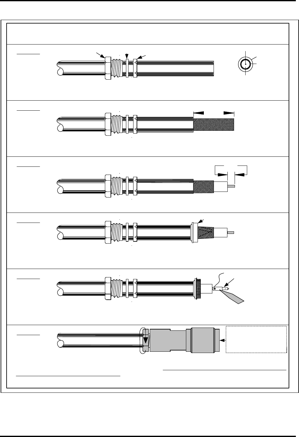
Figure 3.9 – Belden 9913 Amphenol 82-202-1006 Installation
CONNECTOR ASSEMBLY - BELDEN 9913
STEP 1.
9913 CABLE
CUT END OF CABLE EVEN AND SLIDE NUT, WASHER AND V-GROOVE WASHER ONTO CABLE.
ENSURE V-GROOVE OPENINGS POINT TOWARD END OF THE CABLE AS SHOWN.
STEP 2.
AMPHENOL N-TYPE CONNECTOR NO. 82-202-1006
REMOVE 0.359"/9.1 MM OF VINYL JACKET - DO NOT NICK THE BRAID OF CABLE
STEP 3.
STEP 4.
STEP 5.
STEP 6.
0.359"
9.1 MM
COMB OUT BRAID AND FOLD OUT THEN BARE CENTER CONDUCTOR FOR 0.234"/6 MM
0.234"
6 MM
INSERT CABLE AND PARTS INTO CONNECTOR BODY. ENSURE SHARP EDGE OF CLAMP SEATS PROPERLY INTO
GASKET. TIGHTEN NUT (ARROW ) INTO CONNECTOR BARREL USING 2 WRENCHES MAKING SURE CONNECTOR
BARREL DOES NOT TURN ON THE CABLE. NOTE THAT THE CONTACT PIN MUST NOT EXTEND OUT OR BE
VISIBLE FROM THE SIDE. FINALLY, APPLY WATERPROOFING TAPE OVER NUT AND BARREL.
VINYL JACKET
BRAID WIRE
DIELECTRIC INSULATION
CENTER CONDUCTOR
DWG-IDFLEX-ANT-CABLE-04
PULL BRAID WIRES FORWARD AND TAPER TOWARD CENTER CONDUCTOR. PLACE CLAMP
OVER BRAID AND PUSH CLAMP BACK AGAINST END OF CABLE JACKET AS SHOWN.
CLAMP NUT WASHER GASKET
CLAMP
CONTACT PIN
TRIM BRAID TO PROPER LENGTH AND FOLD BACK BRAID WIRES OVER CLAMP. TIN CENTER
CONDUCTOR AND SOLDER CONTACT PIN INTO PLACE. SCRAPE ANY EXCESS SOLDER OFF
OF PIN SO IT WILL BE A PRECISION FIT THROUGH HOLE IN CONNECTOR BODY.
CONTACT PIN MUST NOT
BE VISIBLE FROM THE
SIDE. IF VISIBLE, CABLE
END IS IMPROPERLY
PREPARED! START OVER
IDentity Flex
Hardware Manual – Installation
sirit
Version 2.3 Page 33
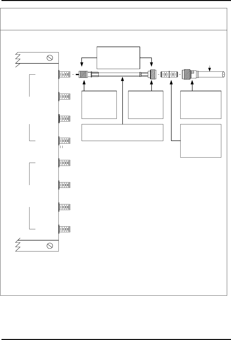
Figure 3.10 – Antenna Cable Adapter Connection
RX1
RX2
RX3
RX4
TX1
TX2
TX3
TX4
RECEIVE TRANSMIT
9913
COAXIAL CABLE RG-58/U OR
BELDEN 8240
*
18"
IDENTITY FLEX
"CABLECON"
ASSEMBLY
9913 CABLE
TO ANTENNA
IDentity Flex ANTENNA CABLE ADAPTER
IDentity Flex READER CHASSIS
MINI-UHF
CONNECTOR
AMP 226600-1
N-TYPE UHF
CONNECTOR
AMPHENOL
82-5375
N-TYPE UHF
ADAPTER
JACK-TO-JACK
AMPHENOL
82-101-RFX
N-TYPE UHF
CONNECTOR
AMPHENOL
82-202-1006
* Note: THE ABOVE CABLE ADAPTER IS
AVAILABLE AS AN OPTION FROM SIRIT BY
QUOTING PART NO.
"IDFLEX-CABLECON"
ADAPTS 9913 TYPE "N" CONNECTOR TO RG-58/U MINI-UHF CONNECTOR
IDentity Flex
Hardware Manual – Installation
sirit
Version 2.3 Page 34
Interface Connections
SYSTEM INTERFACES
The following sections contain descriptions of interfaces, interface connectors,
jumper settings and sync line connectors that will be connected in the field.
Once installed and wired, the entire IDentity Flex system is configured from a PC
or laptop running SIRIT’s IDentity Flex software, ProComm™ or Windows®
HyperTerminal™. The configuration is done on site at the reader location by
connecting a PC’s serial port to the Maintenance Interface identified as “RS-232”.
This configuration may also be performed remotely by use of a dial-up modem
and SIRIT’s Windows®-based IDentity Flex software. Refer to Figure 3.11 below
for the reader chassis layout.
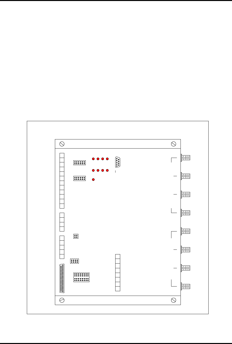
Figure 3.11 – IDentity Flex Reader Connections
1
2
3
4
5
6
7
8
9
10
11
12
1
2
3
4
1
2
3
4
5
RX1
RX2
RX3
RX4
TX1
TX2
TX3
TX4
P1
1
2
3
4
5
6
7
8
DC POWER INPUT
J5
J4 J3
WIEGAND OUTPUTSSYNC
HOST
INTERFACE
DISCRETE
INPUTS/OUTPUTS
RESET D
HOST IN
A
CPU ALIVE
SYNC
HOST OUT
MAINTENANCE
INTERFACE "RS-232"
J1
J2
IDENTITY FLEX READER CHASSIS LAYOUT AND CONNECTOR LOCATIONS
B
C
6
11
6
1
8
9
16
IDENTITY
by SIRIT
READER
P/N-IDFLEX-CB-IV
1 19
20 37
TRANSMIT ANTENNAS
RECEIVE ANTENNAS
DWG-IDFLEX-RDR-01

IDentity Flex
Hardware Manual – Installation
sirit
Version 2.3 Page 35
SERIAL HOST CONNECTIONS – RS-232, RS-422, RS-485
1
All RS-232 connections are made to the DB9F connector identified as “RS-232”
also referred to as the maintenance port or maintenance interface. The Tx, Rx,
and Gnd connections are made to pins 2, 3 and 5 respectively.
RS-232 cable should be a shielded pin-to-pin serial cable – not a Null Modem
cable.
RS-232 connections should not exceed 50 feet in length.
For long distances, RS-232 to RS-422 or RS-232 to RS-485¹ converters should
be employed. RS-422 connections can communicate at distances up to 4000
feet. RS-422 connections require four wires: two, individually shielded, twisted
pairs.
Table 3.2 – Maintenance Port Pin-outs
Pin Signal Function
1 N/C
3 RxD
5 Ground
7 Reset
9 N/C
2 TxD
4 Dload
6 N/C
8 N/C
MAINTENANCE COMPUTER CONNECTION
The maintenance computer interface allows the user to configure the reader
system for the specific application, up-load operating software and transponder
translation lists. The IDentity Flex Windows®-based software additionally
permits downloading operational configuration information. Further, the
maintenance computer interface allows testing of the system’s transmitter,
receiver and all discrete inputs and outputs.
The DOS-based IDentity Flex software manual gives a complete listing of all
menus and sub-menus available via the maintenance interface. To connect to
the maintenance interface, the host computer requires emulation software such
as HyperTerminal™ or ProComm™. ProComm™ emulation software is
recommended. HyperTerminal™ emulation software does not allow for system
software or translation table software uploading. Table 3.3 below lists emulation
settings.
1
Custom RS-485 connections specified by SIRIT
IDentity Flex
Hardware Manual – Installation
sirit
Version 2.3 Page 36
Table 3.3 – Emulation Settings
Baud Rate 9600
Data Bits 8
Stop Bits 1
Parity None
Flow Control None
SYSTEM HOST INTERFACE CONNECTOR AND JUMPERS
Based upon which host protocol is being utilized, the host interface port may be
configured for RS-232, RS-422 or RS-485². The supplied 5-pin host interface
connector is configured for communication with any of the above listed data
transmission protocols. Connections for these should be made as follows:
Table 3.4 – Host Interface Connector Pin Functions
Cable Pin 1 Pin 2 Pin 3 Pin 4 Pin 5
RS-232
RS-422
RS-485
2
Ground
Gnd
Gnd
Gnd
Tx-
NC
RS-422-
NC
Tx+
RS-232
RS-422+
NC
Rx+
RS-232
RS-422+
RS-485+
Rx-
NC
RS-422-
RS-485-
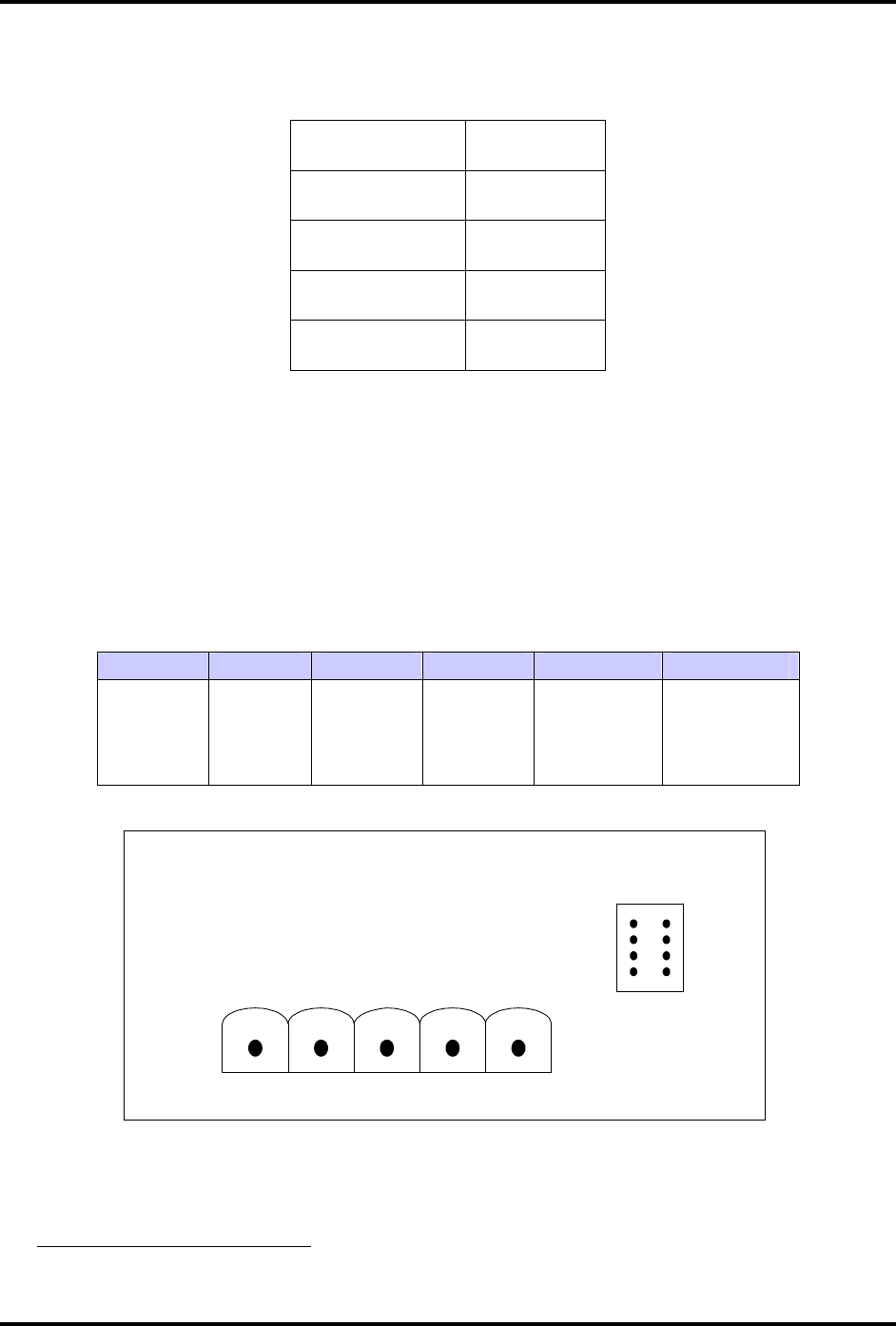
Figure 3.12 – Host Interface Connector and Jumpers
2
Custom RS-485 connections specified by SIRIT
J4
1
GND
2
TX-
3
TX+
4
RX+
5
RX-
HOST
1
2
3
4

IDentity Flex
Hardware Manual – Installation
sirit
Version 2.3 Page 37
SYSTEM HOST INTERFACE JUMPERS
The jumpers located above the host port connector labeled J4 are used to enable
the RS-485 function and apply the appropriate transmission line resistive
termination. If the reader being configured is the last device on a multi-drop
network, the host connector must be terminated using J4-3 and J4-4 inserted.
J4-1 RS-485+ connection to Host Connector Pin 4
J4-2 RS-485- connection to Host Connector Pin 5
J4-3 Connection for termination resistor to Host Connector Pin 3
J4-4 Connection for termination resistor to Host Connector Pin 4
WIEGAND COMMUNICATIONS CONNECTIONS
The Wiegand Interface can be user selectable to any of the standard Wiegand bit
formats. The Wiegand interface is essentially the transmission of data 1 (5 V) or
data 0 (0 V). The Wiegand output protocol may be configured for data stream bit
lengths from 26 to 34 bits. The first and last bits of the data stream are parity bits
and not part of the tag id.
Example: To convey a 23 bit data word length, the Wiegand data bits would be
configured for 26 bits.
For other customized Wiegand formats, please contact SIRIT for more
information.
Wiegand cables are interfaced to the reader at the connector designated as
“WIEGAND OUTPUTS”.
Wiegand cables should be made using two, individually shielded, twisted-pairs
(i.e., a four-wire cable). Each pair should carry one of the data lines and a ground
line (i.e., pair one - Data 0 and GND, pair two - Data 1 and GND).
Whenever connectors or jumpers are to be removed TURN OFF AC POWER
FIRST!
Table 3.5 – Wiegand Interface Specifications
26 Bit Wiegand Interface 34 Bit Wiegand Interface
Total 26 bits Total 34 Bits
Parity Bits Positions 0 and 25 Parity Bits Positions 0 and 33
High parity bit Even (1-12) High Parity Bit Even (1-16)
Low Parity Bit Odd (13-24) Low Parity Bit Odd (17-32)
Most Significant Bit Sent First Most Significant Bit sent First

IDentity Flex
Hardware Manual – Installation
sirit
Version 2.3 Page 38
WIEGAND HOST INTERFACE CONNECTOR
A 12-positon screw-terminal connector is provided for the Wiegand interface.
Table 3.6 – Wiegand Connector Pin-outs
Pin Signal Pin Signal
1 Channel A Port 1 – Data 0 7 Channel C Port 3 – Data 0
2 Channel A Port 1 – Data 1 8 Channel C Port 3 – Data 1
3 Channel A Port 1 – Ground 9 Channel C Port 3 – Ground
4 Channel B
Port 2 – Data 0 10 Channel D Port 4 – Data 0
5 Channel B Port 2 – Data 1 11 Channel D Port 4 – Data 1
6 Channel B Port 2 – Ground 12 Channel D Port 4 – Ground
WIEGAND PORT JUMPER CONFIGURATION
(Jumpers that enable the WIEGAND Ports)
Each of the reader’s four multiplexed remote antennas has an independent
Wiegand Communications port. These 4 ports each have an independent Data
0, a Data 1 and Ground connection at the terminal block connection labeled
Wiegand Outputs. Each may be enabled (jumpers in) or disabled (jumpers out)
as desired. The following is a table identifying each of those jumper connections.
Table 3.7 – Wiegand Jumper Port Layout
Jumper Designator
Jumper Function Jumper Designator
Jumper Function
J1-1 Channel “A” W1-D0+5VDC PU J2-1 Channel “C”
W3-D0+5VDC PU
J1-3 “A” W1-D1+5VDC PU J2-3 “C”
W3-D1+5VDC PU
J1-2 “A” W1 Ground J2-2 “C”
W3 Ground
J1-4 Channel ”B”
W2-D0+5VDC PU J2-4 Channel “D”
W4-D0+5VDC PU
J1-6 “B”
W2-D1+5VDC PU J2-6 “D”
W4-D1+5VDC PU
J1-5 ”B”
W2 Ground J2-5 “D”
W4 Ground
If jumpers are installed, they provide internal 5-volt DC pull-ups and ground, i.e.
Data 0, Data 1 lines and Ground output connections. See Figure 3.13below
showing a typical Pull-Up circuit schematic.
If no jumpers are installed the external Wiegand wiring going to the host system
is opto-isolated from all reader electronic circuitry., The host system will be
required to provide it’s own logic level pull-up voltage and ground.
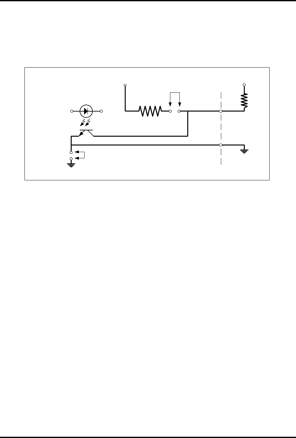
IDentity Flex
Hardware Manual – Installation
sirit
Version 2.3 Page 39
INTERNAL WIEGAND PULL UP CIRCUIT
GND
READER +5V
MAN-IDFLEX-FIG9A
W1
R - PULLUP
VCC ENABLING
JUMPER +5V
GROUND
ENABLING
JUMPER
TO WIEGAND
HOST
TO WIEGAND
HOST GROUND
READER
GROUND
Figure 3.13– Typical Internal Wiegand Pull-up Circuit
Configuration Menu options accessible via the RS-232 Maintenance port allow bit
length, data direction and other protocol options to be set for each of the
Wiegand Ports.
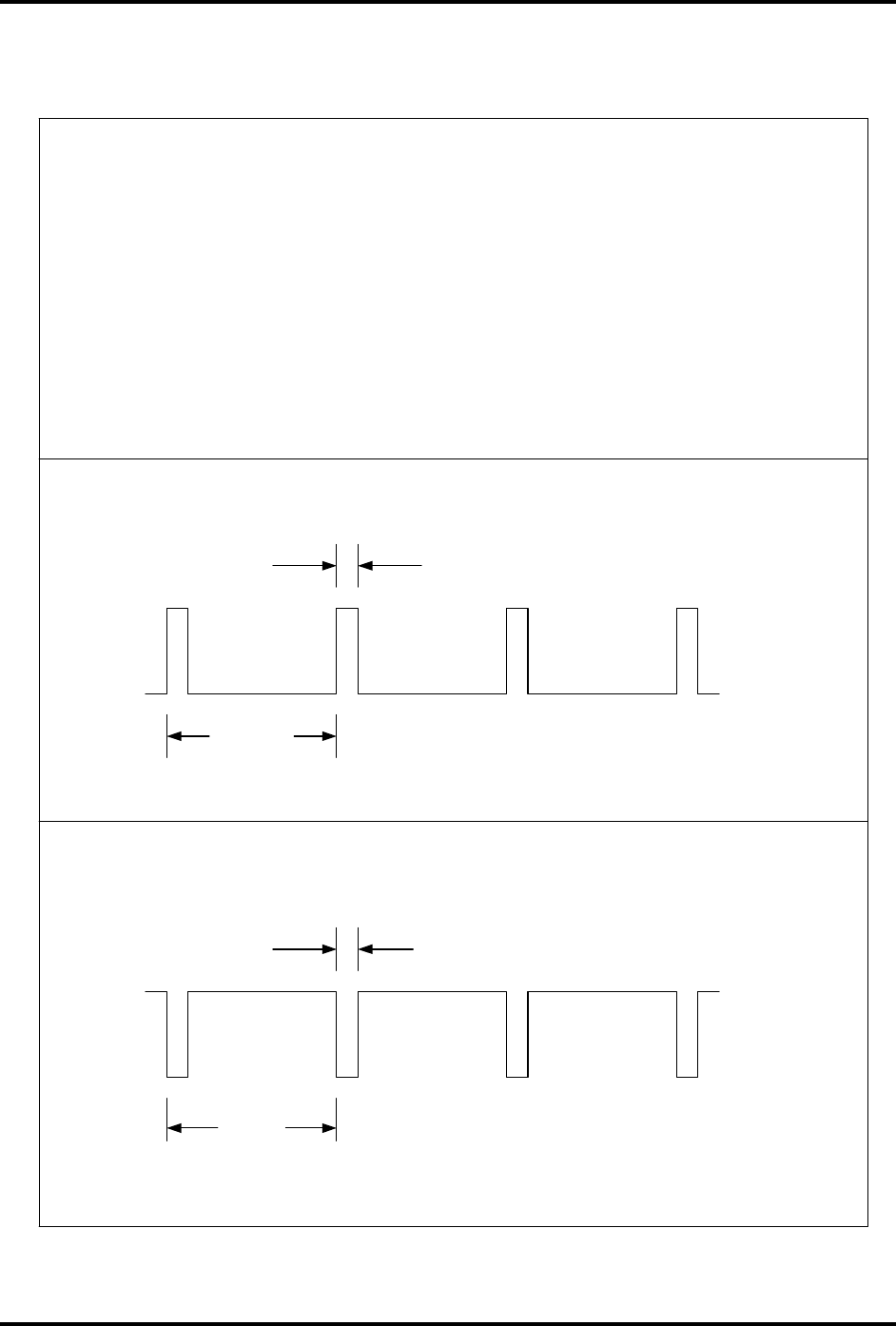
IDentity Flex
Hardware Manual – Installation
sirit
Version 2.3 Page 40
IDENTITY FLEX READER - SYNC PULSE
CHARACTERISTICS
In multi-reader installations, where readers must be synchronized but fail to
synchronize, connections can be verified using an oscilloscope. The following
sync pulse train characteristics are observed on a functional reader, where it
leaves a Master reader or arrives at a Slave. These differential voltages can
also be observed and measured on a peak-reading meter as shown but if an
RMS meter is utilized, indicated readings will be reduced by 50 to 75%. An
example is a peak voltage of 8 volts will read on an RMS meter as
approximately 2 Volts and will be fluctuating.
Placing measurement probe on + terminals
0V
8V
43 mS
1 mS
Placing measurement probe on - terminals
0V
-8V
43 mS
1 mS
DWG-IDFLEX-SYNC-01
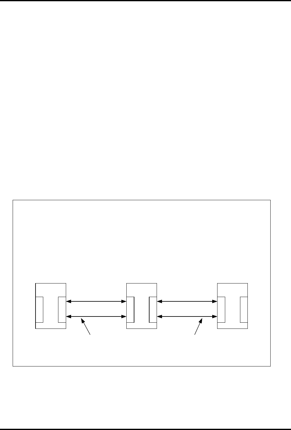
IDentity Flex
Hardware Manual – Installation
sirit
Version 2.3 Page 41
MULTIPLE READER INSTALLATIONS
Installations that utilize more than one reader with adjacent lanes close to other
readers require synchronization. Synchronization allows all separate readers to
transmit simultaneously so that they do not interfere with each other.
Synchronization is accomplished by connecting the reader systems in a daisy
chain fashion where a Previous-to-Next convention is established.
Once connected, the reader system automatically determines which reader
system will generate the synchronization signal and become the master. Slaves
will receive and respond to the synchronization signals. If the readers are not
synchronized, the transmitted signals may interfere with one another, preventing
tag reads.
Separate readers with adjacent lanes must be synchronized. Two or more
separate systems with their antennas closer than 100 feet must be synchronized.
All sync cables are shielded twisted pairs (recommended is use of AWG 18 or
20). The sync cables are connected to terminals labeled “SYNC”.
4
3
2
1
4
3 3
4
1
2
Sync.
Connector
Sync.
Connector
Sync.
Connector
Twisted-Pair cable between readers
DWG-IDFLEX-SYNC-FIG6.2
1
2
Terminating jumpers are IN at readers on the end of the Sync line
Figure 3.14 – Multiple Reader System Sync Connections

IDentity Flex
Hardware Manual – Installation
sirit
Version 2.3 Page 42
SYNC TERMINATION JUMPERS JP1, JP2
J3 jumpers located above and to the right of the sync connection terminals are
utilized to install transmission line termination resistors for reader systems that
are located on the end of the daisy chain. In the example above, reader systems
1 and 3 would have both jumpers installed in J3 pin one and two. Reader system
#2 would have no jumpers installed.
SYNC INTERFACE CONNECTOR J3
Pin 1 Sync + (to Previous Reader System)
Pin 2 Sync – (to Previous Reader System)
Pin 3 Sync + (to Next Reader System)
Pin 4 Sync – (to Next Reader System)
DISCRETE I/O CONNECTOR J5
Table 3.8 that follows is a listing of the discrete I/O connector pinout and signals
available at the 37-pin DISCRETE I/O CONNECTOR, J5.
• Discrete Input signals are TTL compatible.
• Discrete Output signals are jumper configurable to provide either a +5 VDC
or +12 VDC signal for driving low-current solid-state relay control circuitry.
• Each output jumpered for 5 volts is current limited to 100 mA short circuit
current.
• Each output jumpered for 12 volts is current limited to 42 mA short circuit
current.
• The 37-pin female D connector is normally provided by SIRIT.

IDentity Flex
Hardware Manual – Installation
sirit
Version 2.3 Page 43
DISCRETE INPUTS AND OUTPUTS
Table 3.8 – 37-Pin Discrete Input / Output Connector J5
Pin
Number
Signal
Name
Pin
Number
Signal
Name
J5-1 L
AMP
O
UTPUT
C
H
.
A J5-20 G
ATE
C
OMMAND
O
UTPUT
C
H
.
A
J5-2 Lamp Output Ch. B J5-21 Gate Command Output Ch. B
J5-3 Lamp Output Ch. C J5-22 Gate Command Output Ch. C
J5-4 Lamp Output Ch. D J5-23 Gate Command Output Ch. D
J5-5 VCC * J5-24 VCC *
J5-6 VCC * J5-25 VCC *
J5-7 VCC * J5-26 VCC *
J5-8 VCC * J5-27 VCC *
J5-9 VCC * J5-28 Entrance Loop Input Ch. A
J5-10 Gate Position Input Ch. A J5-29 Entrance Loop Input Ch. B
J5-11 Gate Position Input Ch. B J5-30 Entrance Loop Input Ch. C
J5-12 Gate Position Input Ch. C J5-31 Entrance Loop Input Ch. D
J5-13 Gate Position Input Ch. D J5-32 GND
J5-14 GND J5-33 GND
J5-15 GND J5-34 GND
J5-16 GND J5-35 GND
J5-17 GND J5-36 GND
J5-18 GND J5-37 GND
J5-19 GND
* Warning: Any connection to these pins by customer may cause severe
damage to reader. Please contact Sirit technical support prior to making any
connection.
IMPORTANT NOTE: Utilize only one jumper per discrete output. Do not
attempt to configure any one output, that is Output 1-1 for both a +5VDC
and +12VDC output at the same time by installing both jumpers JP5-9 and
JP5-10 or power supply damage may result.
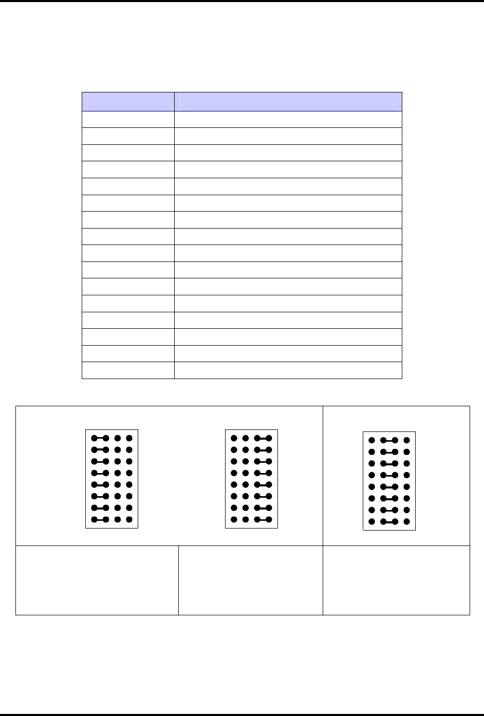
IDentity Flex
Hardware Manual – Installation
sirit
Version 2.3 Page 44
J5 DISCRETE OUTPUT JUMPERS JP1-JP16
Table 3.9 – Jumper Pin-out and Function Table
Jumper Pin # Jumper Function
1 Gate Output A (+5VDC)
2 Lamp Output A (+5VDC)
3 Gate Output B (+5VDC)
4 Lamp Output B (+5VDC)
5 Gate Output C (+5VDC)
6 Lamp Output C (+5VDC)
7 Gate Output D (+5VDC)
8 Lamp Output D (+5VDC)
9 Gate Output A (+12VDC)
10 Lamp Output A (+12VDC)
11 Gate Output B (+12VDC)
12 Lamp Output B (+12VDC)
13 Gate Output C (+12VDC)
14 Lamp Output C (+12VDC)
15 Gate Output D (+12VDC)
16 Lamp Output D (+12VDC)
Figure 3.15 – Discrete Input/Output Jumpers
J5
1
8 16
9
J5 J5
5V 12V 5V 12V 12V5V
LAMP "A"
GATE "A"
GATE "B"
LAMP "B"
GATE "C"
LAMP "C"
GATE "D"
LAMP "D"
ALL JUMPERS ON 1-8
ALL JUMPERS OFF 9-16
5 VOLTS SELECTED
ALL JUMPERS OFF 1-8
ALL JUMPERS ON 9-16
12 VOLTS SELECTED
ALL JUMPERS OFF
ALL JUMPERS PLACED AND
STORED IN
CENTER-OFF ROW
NO VOLTAGE SELECTED
1
8 16
9 9
16
8
1
MAN-IDFLEX-IOCONN-FIG11
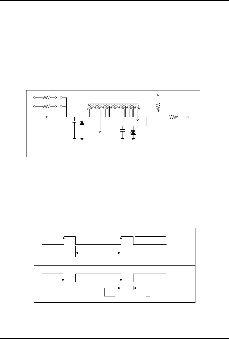
IDentity Flex
Hardware Manual – Installation
sirit
Version 2.3 Page 45
DISCRETE INPUT/OUTPUT FUNCTIONS
Two discrete outputs are provided per reader port. The discrete outputs provide
control signals for the Lane Indicator Light (Lamp Output) and the Lane Gate
(Gate Command). The driving signals are open collectors with jumper-selectable
pull-up voltages of either +5 VDC or +12 VDC. If no jumpers are installed, the
current-sinking capability of the open collector device is 150 mA. If either jumper
is installed, the driving capability of the pull-up voltages is restricted to low
current control of devices such as solid-state relays. The pull-up outputs are not
intended to directly drive magnetic relays.
Figure 3.16 – Typical Input / Output Circuit and Pull- Up Resistors
DISCRETE INPUT POLARITY
There are two discrete inputs per reader channel. The inputs are the Entry Loop
and Gate Position signals. The reader will respond to either an active high or
active low signal for these inputs based upon how the reader is configured. The
activation levels are configurable via the configuration menus. See Figure 3.17.
Figure 3.17 – Examples of Active-High and Active-Low Polarities
1
J5
5
24-27
28
32 - 37
19
LOOP AND GATE
SIGNAL INPUT
VCC
VCC
+12 VDC
VCC
GATE AND
LAMP OUTPUT
SIGNALS
MAN-IDFLEX-IOPU-FIG12
12 VDC
0 VDC
12 VDC
0 VDC
ACTIVE
"HIGH"
ACTIVE
"LOW"
HOLD-OFF
DURATION
PULSE WIDTH
Figure 4.7 - EXAMPLES OF ACTIVE- HIGH AND ACTIVE-LOW POLARITIES

IDentity Flex
Hardware Manual – Installation
sirit
Version 2.3 Page 46
DISCRETE OUTPUT POLARITY, PULSE WIDTH AND DELAY
There are two discrete outputs per reader channel. The outputs are LAMP and
GATE. The active levels for both of these outputs are configurable to active high
or active low. The Pulse Width and mandatory time delay between successive
output pulses are also configurable via the configuration menus.
OPTO-ISOLATED RELAY CONTROL BOARD
As an option, SIRIT offers 4-module or 16-module opto-isolated relay
motherboards that provides either AC or DC input modules to satisfy the
switching requirements of a wide range of lamps and gates. The pre-wired relay
motherboard interfaces to J5, the 37-pin I/O connector and provides terminal-
block connections for peripheral device wiring. The cable assemblies for the
relay boards and the relay support panel are also provided in the option package.
Gate Input or Loop Input Relays
Under certain conditions users may elect to arm (turn on) the SIRIT antenna
based upon a change of state of a gate position or loop output circuit. Arming the
antenna can be accomplished by using the gate position input or both inputs tied
in series.
Two methods are available for this purpose:
Dry Contact Switch or Relay
A dry contact relay (no voltage being applied) is connected between the reader’s
discrete I/O connector ground and desired discrete input pin. The active logic
level for the discrete input (reader responds to either a high or low) may be
configured via the input polarity mask in the system setup menu. No outside
voltage source is required or desired to provide a discrete input signal to the
reader. If noise or voltage is unintentionally placed on either the ground or
discrete input lines connected to the reader, a second isolation relay will break
the noisy circuit.
AC or DC Input Relay Module
The second method of activating a discrete input is by using an opto-isolated
input relay module. The modules are designed to accept either an AC or DC
input signal within the modules specified operating range. The advantage to
using the opto-isolated module is that it presents an optical barrier between the
input equipment and the reader.

IDentity Flex
Hardware Manual – Installation
sirit
Version 2.3 Page 47
Gate Output or Lamp Output Relays
Under certain conditions users may elect to have the IDentity Flex reader system
vend a gate or lamp output directly. Under these conditions SIRIT makes
available an opto-isolated output relay module that can handle either AC or DC.
The relay module typically drives the gate or lamp’s control relay input.
Connection in this fashion provides an optical barrier between the output circuit
and the SIRIT reader.
This relay is required as there is typically a load voltage on the controlled side of
the gate or lamp output relay.
Relay Wiring
Relay wiring tables can be found in the section starting on page 65.
MEMORY GATE OPERATION
The reader supports operations with memory and non-memory lift gate devices.
A lift gate operates in the following fashion:
• A command is issued by the reader to the gate controller which will lift the
gate mechanism.
• The vehicle which was read will move under the gate.
• The gate remains up until the vehicle exits the gate area and crosses an exit
indicator mechanism such as a road-embedded pickup loop.
• The controller then determines that the vehicle has left and lowers the gate.
NON-MEMORY LIFT GATE
The gate will only respond to a gate up command if it is in the “DOWN”
position. There is no memory provision to store additional gate “UP” commands
that may be sent by the reader while the gate is “UP”. “GATE UP” commands
generated by the reader during the time that the gate is up will be lost.
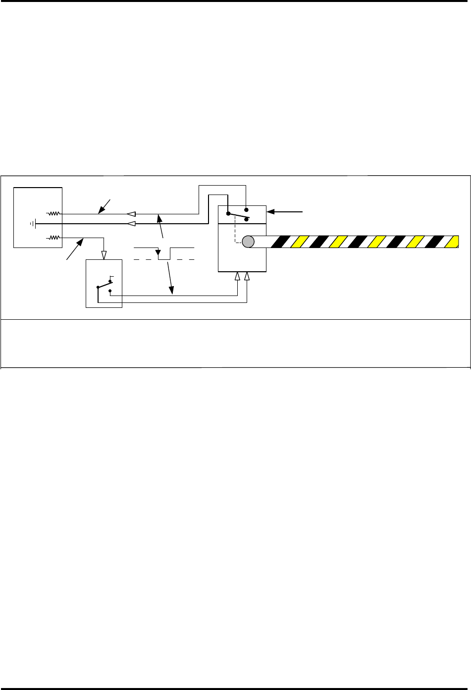
IDentity Flex
Hardware Manual – Installation
sirit
Version 2.3 Page 48
IDentity Flex reader operations with non-memory lift gates require that a gate
position feedback mechanism be employed from the lift gate to the reader and
that the reader be configured to operate with non-memory lift gates. Based upon
the specific gate, the feedback signal may be an opening or closing contact when
the gate is in the “UP” position. The feedback signal is connected to the Gate
Position Discrete Input for the lane in use. When configured for non-memory gate
operation, the reader will not send a “GATE UP” command to the gate controller
if the feedback signal is in an ACTIVE state. Once the feedback signal goes to an
in-active state, the next in-queue “GATE OPEN” command will be sent. See
Figure 3.18 following for a typical schematic.
Figure 3.18 – IDentity Flex Non-Memory Lift Gate Operation
MEMORY LIFT GATE OPERATION
“GATE UP” commands sent by the reader to the gate controller while the gate is
in the down position will lift the gate. “GATE UP” commands sent by the reader to
the gate controller while the gate is in the “UP” position will be stored in the gate
controller memory. When the gate lowers, the next in-queue “GATE UP”
command will lift the gate. This process will continue until all “GATE UP”
commands have been utilized emptying the memory buffer. No gate position
feedback mechanism between the gate controller and the reader is necessary.
The reader will send a “GATE UP” command to the gate controller at the time
that they are created by a vehicle read event. The operational condition of the
gate controller has no effect on reader operations. Please refer to Figure 4.10
below for the memory gate schematic.
NC
NO
10
37
20
C
NO
NC
C
RELAY
MODULE
LANE "A" GATE POSITION INPUT
MASKED TO ACTIVE-LOW
LANE "A"
GATE OPEN
COMMAND
OUTPUT SET
TO ACTIVE-
LOW
GATE POSITION SWITCH CLOSES
WHEN GATE IS UP
READER IS CONFIGURED FOR NORMAL GATE OPERATION IN I/O PARAMETERS BY
SELECTION #8 "SET LANES WITH MEMORY GATES" EXAMPLE: < . . . . > WHERE NO LANES HAVE
MEMORY GATES AND NON-MEMORY GATES ARE REPRESENTED BY DOTS.
ACTIVE-LOW
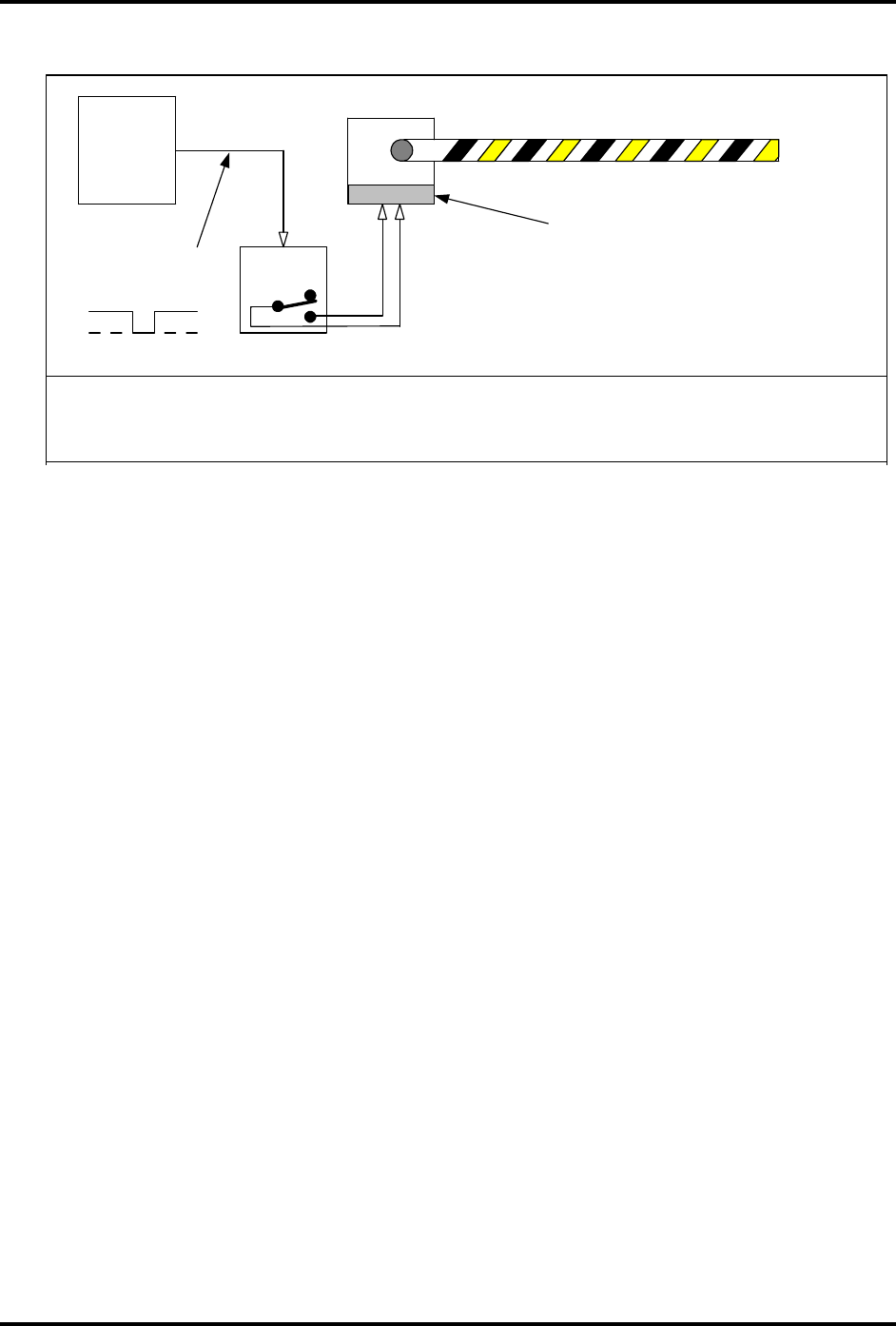
IDentity Flex
Hardware Manual – Installation
sirit
Version 2.3 Page 49
Figure 3.19 – Memory Lift Gate Operation
POLLING SEQUENCES AND INDICATOR LIGHTS
The following table describes the indicating LEDs found on the reader. Under
normal on-line operation, all of the indicating functions below are typical.
However, under diagnostic “TEST HARDWARE” operation, the indicating
functions completely change to indicate diagnostic and test results.
For example the ANT “A” LED which illuminates to indicate a good tag read
under normal operation, will also illuminate under “TEST HARDWARE”
operations when selection #4 is invoked to “Trigger ABCD Gate Outputs”. In this
case the channel “A” LED flash indicates that the channel “A” discrete output
circuit was pulsed, allowing one to test his associated relay or other device on
that channel. Be aware that most “Test Hardware” functions will take the
reader Off-Line for the duration of the test. Refer to the Diagnostics section
starting on page 56.
MEMORY GATE
with STORED GATE
COMMANDS
FLEX
READER
GATE OPEN COMMAND
ACTIVE-LOW
READER IS CONFIGURED FOR MEMORY GATE OPERATION IN I/O PARAMETERS BY SELECTION #8
"SET LANES WITH MEMORY GATES" EXAMPLE:
<. B . . >
WHERE LANE "B" HAS A MEMORY GATE REPRESENTED
BY ITS CHANNEL LETTER AND LANES A, C AND D DO NOT HAVE MEMORY GATES, REPRESENTED BY DOTS.
CONTROL
RELAY
MEMORY

IDentity Flex
Hardware Manual – Installation
sirit
Version 2.3 Page 50
Table 3.10 – Indicator LEDs
LED LED Description
Port A (1) During normal operation, continuous illumination indicates
when tag is being read by Port A of the reader system.
During test operation, used to indicate condition of discrete
inputs
Port B (2) During normal operation, continuous illumination indicates
when tag is being read by Port B of the reader system.
During test operation, used to indicate condition of discrete
inputs
Port C (3) During normal operation, continuous illumination indicates
when tag is being read by Port C of the reader system.
During test operation, used to indicate condition of discrete
inputs
Port D (4) During normal operation, continuous illumination indicates
when tag is being read by Port D of the reader system.
During test operation, used to indicate condition of discrete
inputs
Tag Read
(5)
Indicates when information is being sent to the Host System by
the Reader System. Flashes for one second when tag
information has passed all internal filters and is sent on to the
host system.
Host RCV
(6)
Indicates when information is being received by the reader
from the host system
Sync
Indicator (7)
On=Master, Off=No Sync/Searching for sync, Flashing = Slave
CPU Active
(8)
Flashing indicates that the Central Processing Unit is
functioning
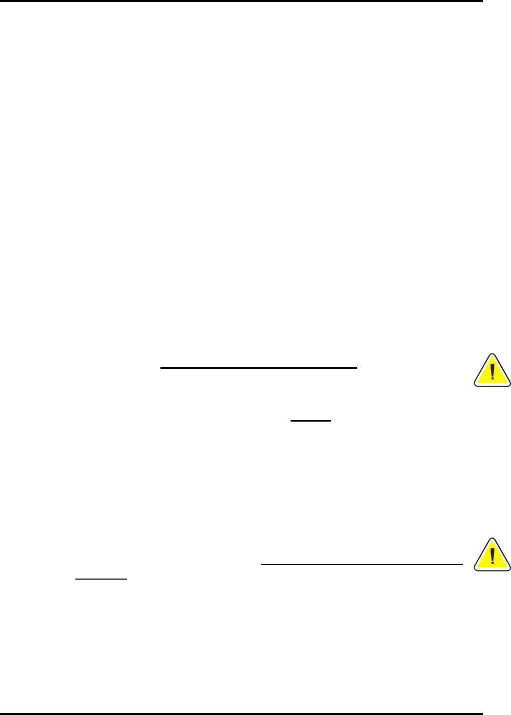
IDentity Flex
Hardware Manual – Transponder Usage
sirit
Version 2.3 Page 51
4.
4.4.
4.
Transponder Usage
Transponder UsageTransponder Usage
Transponder Usage
Metal-Oxide in Windshields
Metal Oxide is commonly used as a tinting agent in windshield glass. Some
vehicle models equipped with metal-oxide windshields can decrease the
transmission of radio frequency (RF) energy through the glass and may inhibit or
affect the performance of such devices as cell phones, garage door openers and
in-vehicle transponders. Metal-oxide windshields can affect any RF transmission.
Should the transponder be affected by the metal-oxide windshields, SIRIT
recommends either relocating the internal transponder or utilizing its exterior-
mounted license plate transponders that are unaffected by windshield content.
Both interior (IDentity Flex) and exterior (T-21 readable) transponders are
available from SIRIT.
Transponder Testing
SIRIT recommends that prior to affixing the transponder to the windshield,
that resellers/users test the transponder to determine if the windshield contains
metal-oxides by following these steps:
• Hold the transponder by hand on the inside of the windshield in the
position and orientation shown in the mounting instructions.
• Drive the vehicle through the appropriate lane under the antenna.
• A good read will be indicated by the gate opening or the antenna LED
illuminating (if this option is installed). If the system registers a good
read then your vehicle’s windshield does not contain RF-inhibiting
content and you can proceed with transponder mounting as described
in the mounting instruction sheet.
• If the system does not read your transponder (the gate does not open
or the antenna LED does not illuminate), then your vehicle’s windshield
may contain metal-oxide and the transponder should not be
mounted to the windshield.
• To confirm that the metal-oxide windshield was the reason the system
did not read the transponder, hold the transponder outside the vehicle,
overhead, on the driver’s side, in the orientation shown on the
mounting instructions. Drive through the lane under the SIRIT antenna.
If the gate opens, the windshield most likely contains metal-oxide or
other RF-inhibiting material.
• Users should contact their reseller/administration who will locate
another windshield location or replace the transponder with an exterior-
mount license plate transponder.
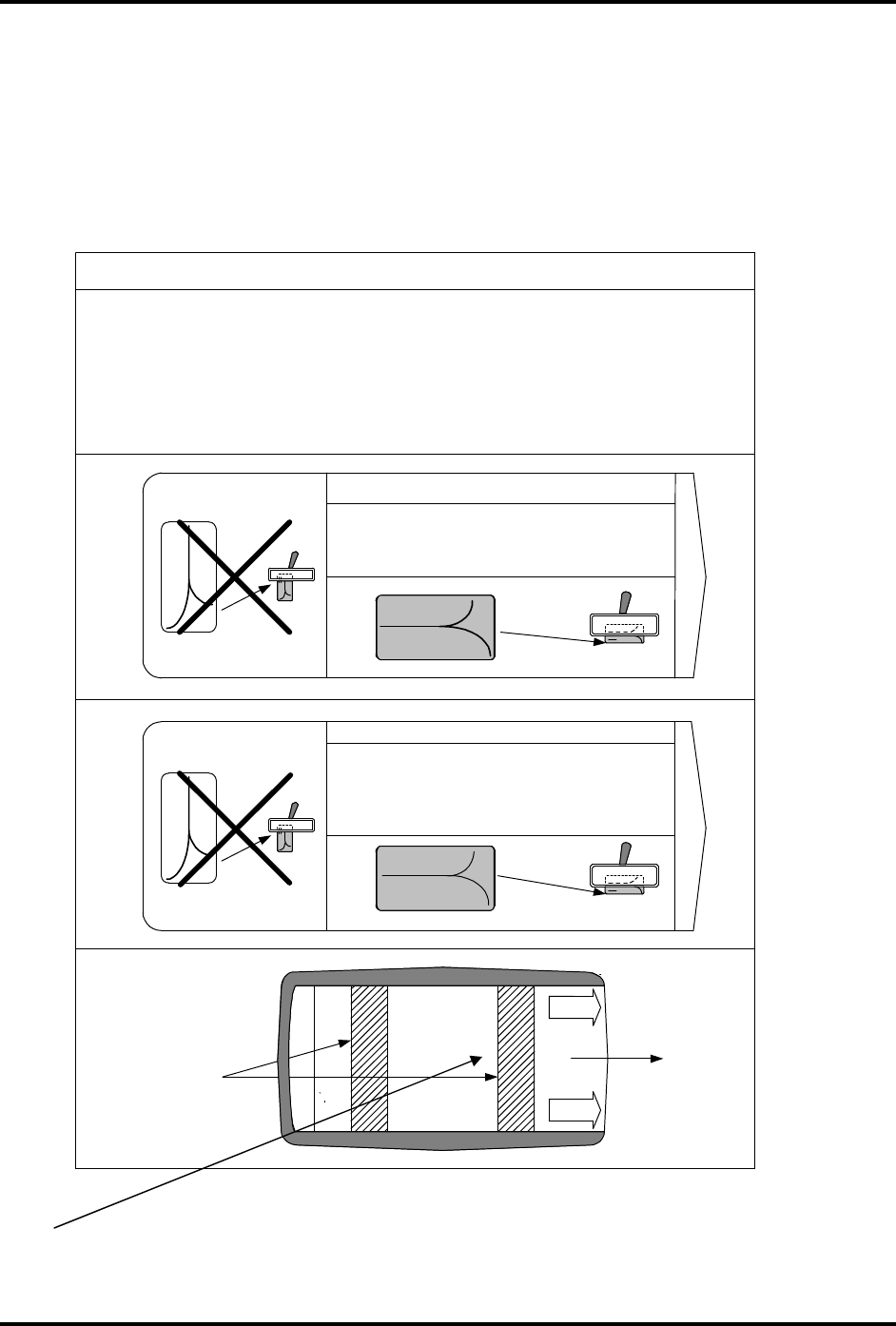
IDentity Flex
Hardware Manual – Transponder Usage
sirit
Version 2.3 Page 52
Transponder Mounting
IDENTITY FLEX & S-FLEX TRANSPONDER
Follow the mounting instructions on the card attached to the transponder :
**Placement for SFlex adhesive is similar (utilizes 3 pieces of adhesive)
PLEASE ENSURE WINDSHIELD IS CLEAN AND FREE OF DIRT.
Figure 4.1 – IDentity Flex Transponder Installation
IDentity Flex Transponder Placement
SLIDING
BATTERY
COVER
VELCRO STRIPS OR
BLACK ADHESIVE
STRIPS
POSITIONED
VERTICALLY
IDentity Flex transponders are 4 x 2.5 x 0.5 inches in size. They must be affixed
inside the vehicle to the top of the windshield behind the rear-view mirror with the
velcro or double-sided tape supplied. Transponders must be positioned at least 3
inches away from the sides of the windshield and away from metal. On vehicles
fitted with oxide laminate windshields, do not mount the transponder over the oxide
laminate - only on the clear glass portion. Follow the directions as shown below.
BACK VIEW
IDentity
by Sirit
NO !
IDentity Flex Transponder Placement
INSTRUCTIONS: (1) Clean inside of windshield (2) Remove the
clear protective backing from both velcro strips (3) Firmly press
the transponder onto the windshield behind the rear-view mirror
in the position and orientation as shown.
PULL TO REMOVE
Transponder affixed to
windshield
IDentity
by Sirit
NO !
S - Flex Transponder Placement
ATTENTION! This transponder will be de-activated if it is
removed from the windshield after installation.
INSTRUCTIONS: (1) Clean inside of windshield (2) Remove the
clear protective backing from the black adhesive strips (3)
Firmly press transponder onto windshield behind the rear-view
mirror in the position and orientation as shown.
Transponder affixed to
windshield
PULL TO REMOVE
MAN-IDFLEX-FIG6B
IDentity
by Sirit
IDentity
by Sirit
SLIDE
TO OPEN
SLIDE
TO OPEN
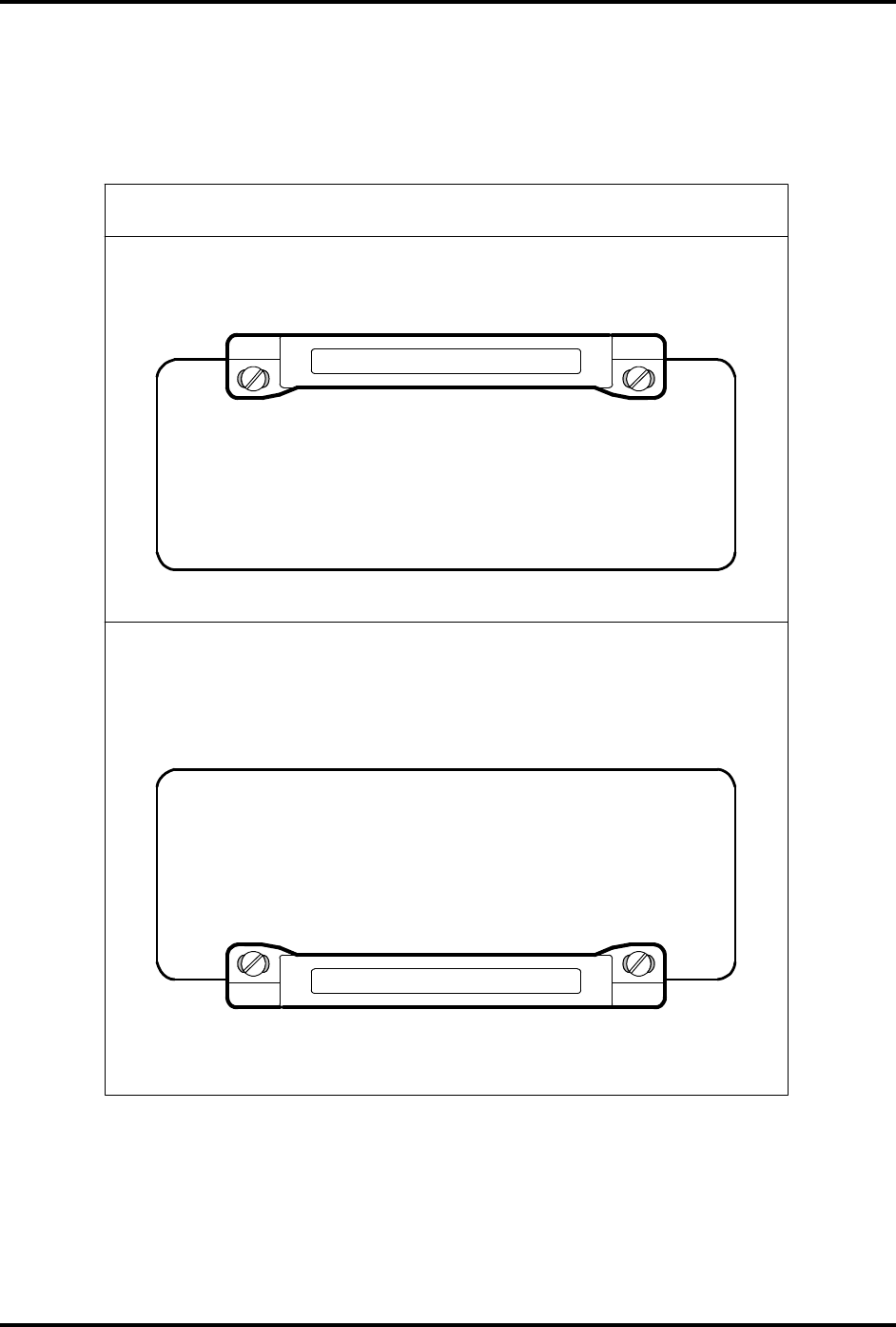
IDentity Flex
Hardware Manual – Transponder Usage
sirit
Version 2.3 Page 53
EXTERNAL MOUNT TRANSPONDER
Follow the mounting instructions below for the external mount transponder.
Figure 4.2 – External Mount Transponder Installation
MOUNTING INSTRUCTIONS - LICENCE PLATE TRANSPONDER
O P T I O N 1
DWG-IDFLEX-TAG-02A
O P T I O N 2
THIS TRANSPONDER MUST BE MOUNTED 1) OVER METAL 2) IN A POSITION NOT
TO OBSTRUCT THE PLATE NUMBERING VIEW
THIS TRANSPONDER MUST BE MOUNTED 1) OVER METAL 2) IN A POSITION NOT
TO OBSTRUCT THE PLATE NUMBERING VIEW
IDentity Flex
Hardware Manual – Transponder Usage
sirit
Version 2.3 Page 54
IDENTITY TITLE 21 TOLLING APPLICATION
TRANSPONDER
Follow the mounting instructions below for the Title 21 transponder.
Figure 4.3 – Title 21 Transponder Installation
Tolling Agency Transponder Placement
THIS FRONT OF TRANSPONDER TAG MUST FACE DRIVER WHEN INSTALLED ON
WINDSHIELD
BACK OF TRANSPONDER TAG IS ATTACHED TO WINDSHIELD BEHIND REAR VIEW
MIRROR. PEEL OFF PROTECTIVE BACKING OF VELCRO STRIPS AND ALIGN VELCRO
STRIPS VERTICALLY AS SHOWN AND ATTACH TO WINDSHIELD GLASS.
VELCRO
STRIPS
POSITIONED
VERTICALLY
BACK VIEW - FLAT SIDE OF TRANSPONDER
BEEPER HOLE
FRONT VIEW - ROUNDED SIDE OF TRANSPONDER
LOGO EXAMPLE ONLY
- LOGO MAY BE ON
FRONT OR BACK OF
TRANSPONDER
DWG-IDFLEX-TAG-03A

IDentity Flex
Hardware Manual – Transponder Usage
sirit
Version 2.3 Page 55
Conversion Procedure for T21 Transponders
This conversion procedure is utilized by SIRIT’s DOS-based software to allow
Title 21 (T21) transponders to be read by the IDentity Flex system. Since the
IDentity Flex Reader requires each transponder ID to be in hexadecimal format
they must first be converted to hex and then entered via the conversion utility,
which will update the tag list file.
1.)
Boot up the reader and select menu option “3 - Tag List Maintenance”. <3>
<ENTER>
2.)
From the Tag List menu select menu option “6 – Manually Add Tag to Update
List”. <6> <ENTER>
3.)
Select menu option “T” for a T21 type transponder. <T> <ENTER>
4.)
At the screen option “Enter Search ID in HEX” – Enter the 8-digit number shown
on the transponder’s label and <ENTER>. Another way to find this number is to
have the system read the tag and then record the number that comes up on the
screen.
5.)
At the screen option see “Enter Translate ID in HEX”. This is the number that
the customer will assign to that tag. This number must be entered in hexadecimal
format so the facility code/ID or Group#/System Code/ID will need to be
converted into HEX first. See example below. Input the 8-digit number and
<ENTER>.
o Example:
o Customers Facility Code in decimal: Facility Code 200
o Customers desired transponder Number in decimal: Tag # 1201
o 200 in decimal is 00C8 in hexadecimal
o 1201 in decimal is 04B1 in hexadecimal
o Put both hex numbers together (FC plus Tag#) to create the following
hexadecimal number: 00C804B1
o Type the 8-digit hexadecimal number into the “Translate ID in Hex” field.
6.)
At the screen option “Tag Status (ALLOW or BLOCK [A/b]” select “A” to
ALLOW tag access and <ENTER>
7.)
Select “X” to exit from the program, then “Y” to save changes.
Adding External Mount Transponders to the
Tag List
Note that the external-mount license plate transponder is a T-21 type and is not
an IDentity Flex transponder. Therefore any of the T-21 transponders so issued
will need to be coded into the TAG MAINTENANCE LIST via the maintenance
port with a lap-top or PC since T-21 tags function differently using hex ID’s.
To add external-mount transponders to the tag list, follow the same procedure for
converting Title 21 tags, detailed above.

IDentity Flex
Hardware Manual – Diagnostics and Troubleshooting
sirit
Version 2.3 Page 56
5.
5.5.
5.
Diagnostics &
Diagnostics & Diagnostics &
Diagnostics &
Troubleshooting
TroubleshootingTroubleshooting
Troubleshooting
This section is intended to help you identify and correct some common problems
that can occur. For additional information or assistance with any query, please
call SIRIT at 1-877-492-0101ext. 2550.
Diagnostic Features
The IDentity Flex reader possesses extensive diagnostic testing features which
are initiated and manipulated by the maintenance computer. The testing features
include:
1. Echo ABCD Loop Inputs to LEDS
2. Echo ABCD Gate Inputs to LEDS
3. Trigger ABCD Lamp Outputs
4. Trigger ABCD Gate Outputs
5. Read Tags and Display Results
6. Test Host Serial Port
7. Test Wiegand Port
8. Test SYNC Port
9. Test Static RF Power
10. Test RF Noise Detection
When the reader system is commanded to perform test mode operations, normal
reader functions are suspended and under menu options 1, 2, 3 or 4, the ANT A,
ANT B, ANT C and ANT D indicator LEDS become Discrete I/O Indicator lights.
PERFORMING TESTS UTILIZING MENU OPTIONS 1 OR 2
Menu options 1 or 2 allow testing of all discrete inputs (Loops and Gates). Logic
conditions of the discrete inputs are reflected upon the ANT A, B, C and D
indicator lights. For example, utilizing menu option #1, “ECHO ABCD LOOP
INPUTS TO LEDS”, if the ABCD Loop Inputs are configured for active-low inputs
and there are no signal lines connected to the input connector, the inputs are
floating high and therefore the ANT A, B, C and D indicator lights will be off. Any
of the inputs that are then connected to a ground or see the normally-open
contacts of a relay go closed will be simulating an active-low input signal and will
cause the associated indicator light to illuminate.

IDentity Flex
Hardware Manual – Diagnostics and Troubleshooting
sirit
Version 2.3 Page 57
Conversely if the Loop Input is configured for active-high operation, the inputs will
likely be at ground potential due to being connected to the closed contacts of a
relay or device somewhere. When those contacts open due to some system
activity, the reader’s pull-up resistor momentarily pulls that input voltage up and
that will cause the associated LED to illuminate.
PERFORMING TESTS UTILIZING MENU OPTIONS 3 OR 4
Menu options 3 or 4 allow testing of all discrete outputs (Lamps and Gates).
When one of these options is selected, the discrete output may be triggered by
command from the maintenance computer keyboard. The antenna A, B, C or D
indicator light will illuminate when a specific discrete output is commanded. An
output pulse that conforms to the menu configured polarity, pulse width, hold-off
settings and at a voltage level of 5 or 12 VDC as determined by installed jumpers
will be generated at the discrete output connector.
Troubleshooting
COMMON PROBLEMS AND SOLUTIONS
Problem No. 1: No power
Indicator: No lights on board (in particular CPU ALIVE or flashing
SYNC)
Checklist Solutions Reference
Check incoming voltage at power
terminal trip. Should be 120 VAC.
Correct problem with 120 VAC
supply. Reset circuit breaker or
replace AC line fuses at panel.
p. 19
p. 24
p. 34
Check DC Power Supply voltages on
Flex reader terminals. See Figure 3.4 for
DC voltages.
If incorrect or no DC output
voltages found replace DC
power supply module.
Figure 3.5
p. 26
Check AC line fuses in power supply. Replace AC line fuses in DC
power supply. Measure
voltages.
p. 24
Check power cabling for damage. With AC power disconnected
replace defective wiring.
p. 19

IDentity Flex
Hardware Manual – Diagnostics and Troubleshooting
sirit
Version 2.3 Page 58
Problem No. 2: Transponders do not read
Indicator: Holding a transponder in front of antenna, channel lamp/tag
read lamp does not light up
Checklist Solutions Reference
Check that 120 VAC power is available.
Check that DC Power Supply functions
properly and outputs correct DC
voltages.
Restore AC power or replace
DC power supply.
See
section
above
Check reader for loose RF connectors. Make sure RF connectors are
tight.
p. 18
Check antenna for loose RF connectors. Make sure connectors are tight
and that waterproofing is in
place.
p. 18
Check reader RF output level. Check software settings.
Connect RF wattmeter and 50-
ohm load to reader. There
should be a 2 Watt CW output
with a software setting of 250.
Set to correct RF level.
See
software
manual
If an RF cable test set is available
(example Bird AT-800) check antenna
system VSWR. VSWR should be 1.1 or
less.
With the Flex reader OFF,
connect coaxial cable test set.
Use cable
test set
Check for shorts or opens in coaxial
cables.
If broken or bare wire exposed,
replace cable. Test with
ohmmeter. Test with coaxial
cable test set or reflectometer.
Use DMM
Use cable
test set
If there is more than one reader, check
synchronization.
Make proper connections as per
section on reader
synchronization.
p. 41
Check configuration of arming loop. Check software settings to
determine whether arming loop
is enabled or disabled
See
software
manual
Check operation of arming loop Make sure proper signals are
being received at reader.
Measure RF output power A directional Wattmeter or Rel.
DB meter is required.
Contact
SIRIT for
more
information
.

IDentity Flex
Hardware Manual – Diagnostics and Troubleshooting
sirit
Version 2.3 Page 59
Problem No. 3: Poor or reduced read range
Indicator: Holding a transponder in front of antenna, maximum read range is
less than 3 or 4 feet, or transponders read intermittently
Checklist Solutions Reference
Check for faulty cable connection or
break in cable
Using an Ohm meter, verify that
the outer shield and inner
conductor are not shorted.
Once this is verified, short one
end of the cable, using the Ohm
meter again, check to ensure no
breaks in the cable.
Observe the center pin in the N
connector to ensure it is not
recessed and well seated.
Check sync pulse Ensure sync pulse is present
Check reader software configuration Ensure that RF power settings
for Flex and T21 Uplink and
Downlink are set properly.
See
software
manual
Check that the correct coaxial cable is in
use for the distance covered between
reader and antenna.
Ensure that excessively lossy
cable is not in use, for example
using RG-58/U to reach 100 feet
away. Refer to Table 2.1 for
cable distances permitted
p. 8
p. 17
p. 27
Check windshield for metal oxide. If windshield contains metal
oxide replace transponder with
external license plate
transponder, otherwise consult
with vehicle manufacturer for
correct location for internal
transponders.
p. 51
Check mounting orientation of
transponder on windshield.
Rotate or re-position
transponder and re-mount
according to proper mounting
instructions.
p. 52
Check orientation of antennas. Antennas
should beam down onto the windshield
from above, not sideways across the
windshield from the side.
Re-adjust antenna to correct
position beaming down onto
windshield. Ensure that antenna
is not beaming across the lane
at a 90-degree angle.
p. 7
p. 20
p. 22
p. 22
Check reader for loose RF connectors. Make sure RF connectors are
tight.
p. 18

IDentity Flex
Hardware Manual – Diagnostics and Troubleshooting
sirit
Version 2.3 Page 60
Checklist Solutions Reference
Check antennas for loose RF
connectors.
Make sure RF connectors are
tight and waterproofing is in
place.
p. 18
Check for large metal objects in front of
antenna that can reflect signals.
Move antenna location so
reflections can be eliminated or
reduced.
p. 16
Check the antennas’ proximity to one
another; an antenna should not be
beaming right into another antenna at
close range. Check site layout plan.
Move antenna locations so that
antennas are behind each other,
minimizing the possibility of
reflections from an antenna.
p. 23
Check the coaxial cables for shorts or
opens or poor condition.
Use ohmmeter to test for shorts
or opens. Use Cable Test Set to
measure RF condition of cable.
p. 18
Use cable
test set
Check synchronization between multiple
reader systems.
Make proper connections and
ensure sync jumpers are correct.
Use oscilloscope to observe and
measure 8-volt sync pulse train.
p. 41
Problem No. 4: Reader will not communicate through the host serial
port or maintenance port.
Indicator: Transponders are being read properly but no data is being
received through the host serial port; unable to access
reader menus, via the maintenance port.
Checklist Solutions Reference
Check that the RS-232 cable between
reader’s maintenance port and PC is a
Serial Pin-to-Pin Cable.
If a Null-Modem cable is being
used replace cable with Serial
Pin-to-Pin cable.
p. 19
Check host serial port configuration. Set Host serial port configuration
to 9600 Baud, 8 Data Bits, no
Parity, 1 Stop Bit, no
Hardware
p. 36
See
software
manual
Check host port jumpers. Ensure that RS-232 is
configured at the host port
jumpers and not some other
protocol such as RS-485 or RS-
422.
p. 36
p. 38

IDentity Flex
Hardware Manual – Diagnostics and Troubleshooting
sirit
Version 2.3 Page 61
Check serial cable connections. Reverse the TX-RX pair and
check that the ground is good.
p. 35
Problem No. 5: Reader will not communicate through Wiegand ports
Indicator: Transponders are being read properly but no Wiegand data
is being received through the Wiegand port
Checklist Solutions Reference
Check Wiegand jumpers at JP1 and
JP2
Verify that correct jumpers
are in.
p. 38
Check Wiegand Interface at host PC Verify that Wiegand
transponder format matches
the reader configuration, i.e.
26-bit reader configured to
read 26-bit transponders
See
software
manual
Check Wiegand Interface
connections
Connect to correct terminals p. 38
Check data and ground connections Verify and secure
connections
p. 38

IDentity Flex
Hardware Manual – Diagnostics and Troubleshooting
sirit
Version 2.3 Page 62
Problem No. 6: Reader will not activate relay or incorrect relay activates
Indicator: Transponders are being read properly but the relay will not
activate or the wrong relay activates.
Checklist Solutions Reference
Check jumper settings. Verify that all jumpers are
inserted correctly, 5 volt
jumpers IN for 5 volt relays,
12 volt jumpers IN for 12 volt
relays, etc.
p. 44
Check all relay connections.
Make proper relay
connections.
p. 44
p. 43
Check relay fuses in solid state relays
Replace bad relay fuse. Check
relay fuses
Check ground connections. Verify and secure
connections.
N/A
Check/Inspect relay interface cable Test cable for shorts or opens
N/A
Check main fuse on relay board Replace bad fuse
Verify +5 volts on relay signal Contact SIRIT for service
Problem No. 7 Reader will not function or is frozen or locked up
Indicator: Power/CPU-Alive indicator is on but CPU may be locked up
Checklist Solutions Reference
Check that reader has power Measure voltages at DC
power terminals
p. 26
Check RESET button Push RESET button located
in a small hole beside CPU
lamp for 1 second and reader
will re-boot. RESET button
has the same function as the
power ON/OFF switch
p. 34
If reader is hot, power down and
allow reader to cool down for 15-20
minutes.
Re-apply power and test for
functionality
N/A

IDentity Flex
Hardware Manual – Components, Accessories and Options
sirit
Version 2.3 Page 63
6.
6.6.
6.
Components
ComponentsComponents
Components, Accessories
, Accessories, Accessories
, Accessories
and Options
and Optionsand Options
and Options
IDentity Flex Component Part Numbers
Table 6.1 – IDentity Flex Component Part Numbers
Customer Part Number Description
IDFLEX-TAG-4 4Year IDentity Flex transponder tags
IDFLEX-TAG-4WBOR 4Year IDentity Flex transponder (with
BOR)
IDFLEX-TAG-4LP IDentity Flex License Plate Mount
transponder
IDFLEX-BAT-CLIP Additional 4-Year battery and clip for
IDentity Flex tags
(excludes IDFLEX-TAG-4LP)
IDFLEX-VELCRO Velcro Strips for IDentity Flex tags
IDFLEX-TS-TAPE Tape strips for IDentity Flex tags
IDFLEX-READER-IIe Two-Channel IDentity Flex reader with
NEMA enclosure.
IDFLEX-READER-IVe Four-Channel IDentity Flex reader with
NEMA Enclosure.
IDFLEX-ANT-01 IDentity Flex 12” x 30” antenna with
universal mounting bracket, includes
hardware for a 1-1/2” pole
IDFLEX-CB-II 2-Channel IDentity Flex transceiver unit
IDFLEX-CB-IV 4-Channel IDentity Flex transceiver unit.
IDFLEX-READER-PS IDentity Flex power supply
IDFLEX-MAN-S/W (DOS Version) IDentity Flex Software and Configuration
Guide for DOS
IDFLEX-MAN-S/W (WINDOWS® Version)
IDentity Flex Software and Configuration
Guide for WINDOWS®
IDFLEX-MAN-H/W IDentity Flex Hardware Installation and
Troubleshooting Guide

IDentity Flex
Hardware Manual – Components, Accessories and Options
sirit
Version 2.3 Page 64
Options and Accessories
Table 6.2 – Options and Accessories Part Numbers
Part Number
Description
IDFLEX-ANT-CMB Universal ceiling mount antenna bracket,
Includes U-bolts for a 1-1/2” pole
IDFLEX-ANT-WMB Universal pole/wall mount antenna bracket
IDFLEX-CONN-RG-58/U Connector kit for RG-58/U
Qty. 2 per kit – Amphenol 82-5375
Qty. 2 per kit – AMP 226600-1
IDFLEX-CONN-9913 Connector kit for 9913 cable
Qty. 4 per kit – Amphenol 82-202-1006
IDFLEX-CABLECON Cable adapter kit – adapts Belden 9913 cable Type
N connector to Mini-UHF connector. Includes 18”
of cable, Type N Male to Mini-UHF Male, with
Jack-to-Jack Type N thru-barrel. Qty. 2 per kit
IDFLEX-CRIMP Cable crimp tool for Amphenol 82-5375 and AMP
226600-1 connectors
IDFLEX-CONN-WKIT Outside weather-proofing kit: Qty. 1 – piece mastic
tape, Qty. 1 electrical tape, for 1 outside antenna
connectors
IDFLEX-CABLE-RG58/U-60K 2 ea 50’ RG-58/U Cable, N connector attached, 2
mini UHF Connector assembly included
For Relays and Relay Options, please contact SIRIT
RELAY AC/DC INPUT MODULE 3-30 VDC or 10-60 VAC from source
DRY CONTACT RELAY MODULE Dry contact relay
CABLE ASSEMBLY FOR 2-4 MODULE
RELAY BOARDS
DB-37 connector mates with J5 on reader I/O
connector.
4-MODULE RELAY BOARD 4-Relay mounting circuit board
16-MODULE RELAY BOARD 16-Relay mounting circuit board

IDentity Flex
Hardware Manual – Components, Accessories and Options
sirit
Version 2.3 Page 65
Opto-Isolated Relay Wiring Guide
The following wiring guide will assist the installer in wiring opto-isolated relays.
The four-module boards are detailed below, and the sixteen-module board
section starts on page 67.
Table 6.3 – Four-Module Board Input Specification
Relay Board Input
Control Terminals
Signal Function
Notes
1 VCC +5 VDC Input Orange
2 Ground Input from Reader
Discrete I/O Cable
Green / White
3 Relay Module #1 Control Signal
(Active Low)
4 Ground No Connection required
5 Relay Module #2 Control Signal
(Active Low)
6 Ground No Connection required
7 Relay Module #3 Control Signal
(Active Low)
8 Ground No Connection required
9 Relay Module #4 Control Signal
(Active Low)
Table 6.4 – Four-Module Board Output Specification
Relay Board
Output Terminals
Signal Function
1 Relay Module #1 (+)
2 Relay Module #1 (-)
3 Relay Module #2 (+)
4 Relay Module #2 (-)
5 Relay Module #3 (+)
6 Relay Module #3 (-)
7 Relay Module #4 (+)
8 Relay Module #4 (-)

IDentity Flex
Hardware Manual – Components, Accessories and Options
sirit
Version 2.3 Page 66
Note: The Relay Board Output Terminals are labeled as Relay Module (+) and
Relay Module (-). This convention refers to the direction of the current flow from
the peripheral being controlled. Refer to attached schematic example for Relay
Module #1
Table 6.5 – Discrete I/O Cable
SIRIT P/N: 9796157-0002
Cable Conductor Color
37 Pin Connector
Pin Number
Discrete Output and Input
Function
Black 1 Lamp Output Channel A
White 2 Lamp Output Channel B
Red 3 Lamp Output Channel C
Green 4 Lamp Output Channel D
Red/Green 20 Gate Output Channel A
Orange/Green 21 Gate Output Channel B
Black/White/Red 22 Gate Output Channel C
White/Black/Red 23 Gate Output Channel D
Black/Red/Green 28 Entrance Loop Input Channel A
White/Red/Green 29 Entrance Loop Input Channel B
Red/Black/Green 30 Entrance Loop Input Channel C
Green/Black/Orange 31 Entrance Loop Input Channel D
Orange/Black 10 Gate Position Channel A
Blue/Black 11 Gate Position Channel B
Black/White 12 Gate Position Channel C
Red/White 13 Gate Position Channel D
Orange 5 VCC +5VDC
Blue 6 VCC +5VDC
White/Black 7 VCC +5VDC
Red/Black 8 VCC +5VDC
Green/Black 9 VCC +5VDC
Red/Black/White 24 VCC +5VDC
Green/Black/White 25 VCC +5VDC
Orange/Black/White 26 VCC +5VDC
Blue/Black/White 27 VCC +5VDC
Green/White 14 GND
Blue/White 15 GND
Black/Red 16 GND
White/Red 17 GND
Orange/Red 18 GND
Blue/Red 19 GND
Orange/Black/Green 32 GND

IDentity Flex
Hardware Manual – Components, Accessories and Options
sirit
Version 2.3 Page 67
Blue/White/Orange 33 GND
Black/White/Orange 34 GND
White/Red/Orange 35 GND
Orange/White/Blue 36 GND
White/Red/Blue 37 GND
Table 6.6 - Sixteen- Module Board Input Specification
Relay Board
Input
Control
Terminals
Signal Function
Notes
+V VCC +5 VDC Input Orange
GND Ground Input from Reader Discrete I/O Cable Green / White
1 Ground No Connection Required
2 Relay Module #1 Control Signal (Active Low)
3 Ground No Connection Required
4 Relay Module #2 Control Signal (Active Low)
5 Ground No Connection Required
6 Relay Module #3 Control Signal (Active Low)
7 Ground No Connection Required
8 Relay Module #4 Control Signal (Active Low)
9 Ground No Connection Required
10 Relay Module #5 Control Signal (Active Low)
11 Ground No Connection Required
12 Relay Module #6 Control Signal (Active Low)
13 Ground No Connection Required
14 Relay Module #7 Control Signal (Active Low)
15 Ground No Connection Required
16 Relay Module #8 Control Signal (Active Low)
17 Ground No Connection Required
18 Relay Module #9 Control Signal (Active Low)
19 Ground No Connection Required
20 Relay Module #10 Control Signal (Active Low)
21 Ground No Connection Required
22 Relay Module #11 Control Signal (Active Low)
23 Ground No Connection Required
24 Relay Module #12 Control Signal (Active Low)
25 Ground No Connection Required
26 Relay Module #13 Control Signal (Active Low)
27 Ground No Connection Required
28 Relay Module #14 Control Signal (Active Low)
29 Ground No Connection Required
30 Relay Module #15 Control Signal (Active Low)
31 Ground No Connection Required
32 Relay Module #16 Control Signal (Active Low)

IDentity Flex
Hardware Manual – Components, Accessories and Options
sirit
Version 2.3 Page 68
Table 6.7 - Sixteen-Module Board Output Specification
Relay Board
Output Terminals
Signal Function
1 Relay Module #1 (+)
2 Relay Module #1 (-)
3 Relay Module #2 (+)
4 Relay Module #2 (-)
5 Relay Module #3 (+)
6 Relay Module #3 (-)
7 Relay Module #4 (+)
8 Relay Module #4 (-)
9 Relay Module #5 (+)
10 Relay Module #5 (-)
11 Relay Module #6 (+)
12 Relay Module #6 (-)
13 Relay Module #7 (+)
14 Relay Module #7 (-)
15 Relay Module #8 (+)
16 Relay Module #8 (-)
17 Relay Module #9 (+)
18 Relay Module #9 (-)
19 Relay Module #10 (+)
20 Relay Module #10 (-)
21 Relay Module #11 (+)
22 Relay Module #11 (-)
23 Relay Module #12 (+)
24 Relay Module #12 (-)
25 Relay Module #13 (+)
26 Relay Module #13 (-)
27 Relay Module #14 (+)
28 Relay Module #14 (-)
29 Relay Module #15 (+)
30 Relay Module #15 (-)
31 Relay Module #16 (+)
32 Relay Module #16 (-)
IDentity Flex Hardware Manual – Components, Accessories and Options sirit
Version 2.3 Page 69
SIRIT P/N: 9796150-0002
Figure 6.1 – Sixteen-Module Board Terminals
Slot 1
(Lamp Output Ch A)
Slot 2
(Lamp Output Ch B)
Slot 3
(Lamp Output Ch C)
Slot 4
(Lamp Output Ch D)
Input Control Terminals
+V-GND 1-2-3-4-5-6-7-8-9-10-11-12-13-14-15-16-17-18-19-20-21-22-23-24-25-26-27-28-29-30-31-32
Output Field Terminals
1-2 3-4 5-6 7-8 9-10 11-12
13-14 15-16
17-18
19-20
21-22
23-24
25-26
27-28
29-30
31-32
Slot
1
Slot 2
Slot 3
Slot 4
Slot 5
Slot 6
Slot 7
Slot 8
Slot 9
Slot 10
Slot 11
Slot 12
Slot 13
Slot 14
Slot 15
Slot 16
Slot 5
(Gate Output Ch A)
Slot 6
(Gate Output Ch B)
Slot 7
(Gate Output Ch C)
Slot 8
(Gate Output Ch D)
Slot 9
(Loop Input Ch A)
Slot 10
(Loop Input Ch B)
Slot 11
(Loop input Ch C)
Slot 12
(Loop Input Ch D)
Slot 13
(Gate Input Ch A)
Slot 14
(Gate Input Ch B)
Slot 15
(Gate Input Ch C)
Slot 16
(Gate Input Ch D)
IDentity Flex
Hardware Manual – Component Specifications
sirit
Version 2.3 Page 70
Figure 6.2 - 4 Channel Relay Mother Boards
Output Field Terminals Output Field Terminals
1-2
Slot 1
1-2
Slot 1
3-4
Slot 2
3-4
Slot 2
5-6
Slot 3
7-8
Slot 4
5-6
Slot 3
7-8
Slot 4
Input Control Terminals Input Control Terminals
1 - 2 - 3 - 4 - 5 - 6 - 7 - 8 - 9 1 - 2 - 3 - 4 - 5 - 6 - 7 - 8 - 9
Slot 1 - Lamp
Output Ch. A
Slot 2 - Lamp
Output Ch. B
Slot 3 - Lamp
Output Ch. C
Slot 4 - Lamp
Output Ch. D
Slot 1 - Gate
Output Ch. A
Slot 2 - Gate
Output Ch. B
Slot 3 - Gate
Output Ch. C
Slot 4 - Gate
Output Ch. D
Board A Board B
Figure 4 - Two 4-Channel Relay Mother Boards
DWG-IDFLEX-RELAY-2MB

IDentity Flex
Hardware Manual – Component Specifications
sirit
Version 2.3 Page 71
7.
7.7.
7.
Compon
ComponCompon
Component Specifications
ent Specificationsent Specifications
ent Specifications
Reader System
Environmental
Storage Temperature: -40°C to +60°C
Operating Temperature: -25°C to +60°C
Humidity: 85% non-condensing at 85°C
Vibration: 1g at 15 Hz to 500 Hz
Shock: 5g at 10 ms
Enclosure
Enclosure: NEMA 4X enclosure
Enclosure dimensions: 16” x 14” x 9”
Weight: 7.8 pounds
Transceiver Specifications
Dimensions: 9.5” x 9” x 1”
Weight: 2.5 pounds
Input Impedance: 50 Ohms
Output Impedance: 50 Ohms
Output Power: 33 dBm (2 W, CW Average)
Down-link Modulation: T21 AM, Manchester encoded, 300
Kbps
Up-link Modulation: T21 Frequency shift Keyed, 300
Kbps
2PSK Two Phase Shift Keyed, 150
Kbps
Operating Frequency: 916.25 MHz
DC Power requirements: +12 +/- 0.5 VDC @ 3.5 Ampere
-12 +/- 1 VDC @ 1.0 Ampere
+5 +/- 0.25 VDC @ 1.0 Ampere
Max. continuous power consumption: 20 Watts
Standards: Reads Caltrans Title 21 compliant
transponders
FCC Part 15 Approved
FCC Part 90 Approved
FCC ID M4ZS2301
Industry Canada Type Approval No.
TBD
Power Supply Dimensions: 11.75” x 5” x 3”
Weight: 5 pounds
AC Power Input: 85-264 VAC, 47-93 Hz, 4A

IDentity Flex
Hardware Manual – Component Specifications
sirit
Version 2.3 Page 72
Antenna
FLEX ANTENNA
Dimensions
Dimensions: 30”x 12”x 1.5”
Weight: 7.8 pounds
Specifications
Input Impedance: 50 Ohms
Output Impedance: 50 Ohms
Frequency: 916.25 MHz
VSWR: < 1.5 in band
UNIVERSAL MOUNTING BRACKET
Dimensions
Dimensions: 4” x 4” x 4”
Weight: 1.1 pounds
Transponder
Environmental
Storage Temperature: -40°C to 100°C
Operating Temperature: -25°C to +85°C
Humidity: 85% non-condensing at 85°C
Vibration: 10g, ½ Sine pulse 10ms duration
Shock: 5g, ½ Sine pulse 10ms duration
IDENTITY FLEX AND S-FLEX TRANSPONDER
Enclosure
Enclosure: Polycarbonate weather-resistant
plastic
Dimensions (WxHxD): 4.2” x 2.6” x 0.5”
Weight: 2.2 Ounces

IDentity Flex
Hardware Manual – Component Specifications
sirit
Version 2.3 Page 73
Specifications
Uplink Modulation: 2PSK Two Phase Shift Keyed (150
Kbps)
Operating Frequency: 916.25 MHz
Data Storage: 32 bit transponder ID
Battery Requirements: 3.0 Volts ( non-replaceable cell -
replaceable CR2032 cell with Flex
only ) One cell yields a transponder
life of up to 4 years
Read Range: Up to 25 feet, set by reader and
antenna configuration, cabling length
and power output
EXTERNAL LICENSE PLATE TRANSPONDER
Environmental
Storage Temperature: -40C to 114C
Operating Temperature: -25C to +85C
Humidity: 95% non-condensing at 70°C
Vibration: 10g, ½ Sine pulse 10ms duration
Shock: 5g, ½ Sine pulse 10ms duration
Enclosure
Enclosure: Polycarbonate weather-resistant
plastic
Dimensions (WxHxD): 4.2” x 2.6” x 0.5”
Weight: 2.2 Ounces
Specifications
Uplink Modulation: 2PSK Two Phase Shift Keyed (150
Kbps)
Operating Frequency: 916.25 MHz
Data Storage: 32 bit transponder ID
Battery Requirements: 3.0 Volts (non-replaceable cell)
One cell yields a transponder life of
up to 4 years
Read Range: Up to 25 feet, set by reader and
antenna configuration,
cabling length and power output

IDentity Flex
Hardware Manual – Reference
sirit
Version 2.3 Page 74
8.
8.8.
8.
Reference
ReferenceReference
Reference
Glossary
AC Alternating Current
AM Amplitude Modulation
AVI Automatic Vehicle Identification
BIN Binary
BOR Break on Removal
CRT Cathode Ray Tube - display
COM Communications
CWB Concrete Wall/Pole Bracket, optional mounting pipe with bracket
dB decibel – level of a signal
dBm decibels referenced to one milliwatt of power
DC Direct Current
DC Dealer Code
FC Facility Code
FCID Facility Code Identification
FCC Federal Communications Commission – a regulatory agency
FM Frequency Modulation
IL Issue Level
I/O Input / Output – data doorway to and from a device
KHz Kilohertz – 1,000 cycles per second
Kbps Kilo Bits per Second
mA Milliampere
Mbps Mega Bits per Second
MHz Megahertz – 1,000,000 cycles per second
ms Millisecond
NEMA National Electrical Manufacturers Association
PSK Phase Shift Keying
2PSK Double Phase Shift Keying
RF Radio Frequency (radio frequency energy)
RFID Radio Frequency Identification
RX Receive
RXd Received Data
SYNC Synchronization Signal
TTL Transistor-Transistor Logic – logic circuits
TX Transmit
TXd Transmitted Data
T21 Title 21 (California tolling system)
UHF Ultra High Frequency
UMB Universal Mounting Bracket supplied with Flex antenna
VAC Voltage – Alternating Current
VDC Voltage – Direct Current
VSWR Voltage Standing Wave Ratio
WIEGAND 26, 34 or 50-bit binary-encoded data used in the control industry

IDentity Flex
Hardware Manual – Reference
sirit
Version 2.3 Page 75
List of Figures
Figure 1.1 – System Operation........................................................................................................ 2
Figure 1.2 – IDentity Flex Mounting Options ................................................................................... 7
Figure 2.1 – Typical Parking Access Lane Configuration
............................................................ 11
Figure 2.2 – Typical Gated Access Lane Configurations .............................................................. 13
Figure 3.1 – Antenna Orientation .................................................................................................. 20
Figure 3.2 – Antenna Mounting Angles ......................................................................................... 22
Figure 3.3 - Antenna Lateral Orientation ....................................................................................... 23
Figure 3.4 – Remote Antenna/Reader Connection Diagram ........................................................ 24
Figure 3.5 – Reader Connections.................................................................................................. 26
Figure 3.6 – RG-58/U Amp 226600-1 Installation ......................................................................... 29
Figure 3.7 – RG-58U Amphenol 82-5375 Installation
(Part A)...................................................... 30
Figure 3.8 - RG-58U Amphenol 82-5375 Installation (Part B)....................................................... 31
Figure 3.9 – Belden 9913 Amphenol 82-202-1006 Installation ..................................................... 32
Figure 3.10 – Antenna Cable Adapter Connection........................................................................ 33
Figure 3.11 – IDentity Flex Reader Connections .......................................................................... 34
Figure 3.12 – Host Interface Connector and Jumpers .................................................................. 36
Figure 3.13– Typical Internal Wiegand Pull-up Circuit .................................................................. 39
Figure 3.14 – Multiple Reader System Sync Connections ............................................................ 41
Figure 3.15 – Discrete Input/Output Jumpers ............................................................................... 44
Figure 3.16 – Typical Input / Output Circuit and Pull- Up Resistors.............................................. 45
Figure 3.17 – Examples of Active-High and Active-Low Polarities ............................................... 45
Figure 3.18 – IDentity Flex Non-Memory Lift Gate Operation ....................................................... 48
Figure 3.19 – Memory Lift Gate Operation.................................................................................... 49
Figure 4.1 – IDentity Flex Transponder Installation....................................................................... 52
Figure 4.2 – External Mount Transponder Installation .................................................................. 53
Figure 4.3 – Title 21 Transponder Installation............................................................................... 54
Figure 6.1 – Sixteen-Module Board Terminals.............................................................................. 69
Figure 6.2 - 4 Channel Relay Mother Boards............................................................................... 70
List of Tables
Table 2.1 – Remote Antenna Cable Selection .............................................................................. 17
Table 2.2 – Antenna/Reader Connector Selection........................................................................ 18
Table 3.1 – Legend for Figure 3.4 ................................................................................................. 25
Table 3.2 – Maintenance Port Pin-outs ......................................................................................... 35
Table 3.3 – Emulation Settings...................................................................................................... 36
Table 3.4 – Host Interface Connector Pin Functions..................................................................... 36
Table 3.5 – Wiegand Interface Specifications ............................................................................... 37
Table 3.6 – Wiegand Connector Pin-outs ..................................................................................... 38
Table 3.7 – Wiegand Jumper Port Layout..................................................................................... 38
Table 3.8 – 37-Pin Discrete Input / Output Connector J5 ............................................................. 43
Table 3.9 – Jumper Pin-out and Function Table ........................................................................... 44
Table 3.10 – Indicator LEDs .......................................................................................................... 50
Table 6.1 – IDentity Flex Component Part Numbers..................................................................... 63
Table 6.2 – Options and Accessories Part Numbers .................................................................... 64
Table 6.3 – Four-Module Board Input Specification ...................................................................... 65
Table 6.4 – Four-Module Board Output Specification ................................................................... 65
Table 6.5 – Discrete I/O Cable ...................................................................................................... 66
Table 6.6 - Sixteen- Module Board Input Specification ................................................................. 67
Table 6.7 - Sixteen-Module Board Output Specification ............................................................... 68

IDentity Flex
Hardware Manual – Reference
sirit
Version 2.3 Page 76
Index
37-pin discrete i/o connector.....44
4-mile limit.....16
AC or DC input relay module.....47
AC power cabling.....18, 22
AC power connections.....20
accessories.....64
adjacent lanes.....11, 42
alternate studs.....26
antenna
arming for parking access.....13
bracket.....26
cable adapter connection.....34
cable connectors.....18
cable selection.....18
description.....7
installation.....21
lateral orientation.....22
lead installation.....28
LED feature.....7
location.....7
mounting.....21
mounting brackets.....7
mounting for gated access.....15
mounting for parking access.....11
mounting options.....16
orientation.....11, 22
overhead mounting.....16
paint.....7
read range.....12
side-mounting.....17
specifications.....73
tag read indicator.....7
antenna/reader connection.....25
anti-passback.....13
attenuation.....18
Automatic Vehicle Identification (AVI).....1
back-end host systems.....2, 6
battery
IDentity Flex transponder.....5
baud rate.....37
Belden 8240.....9, 18, 28
connectors.....19
Belden 9913.....9, 18, 28
connectors.....19
Belden 9913 Amphenol 82-202-1006
Installation.....33
bit length.....40
bracket mounting nuts.....26
Break on Removal.....14
buffer.....12
cable connector
dimensions.....29
installation.....29
cable routing.....17
cable run.....9, 17
California Transportation System
Title 21.....1, 3, 5
coaxial cable
tips.....9
coaxial cype N cable connector.....26
common problems and solutions.....58
communication cabling
run with antenna cabling.....18, 22
component specifications.....72
components.....64
conduit.....9
diameter.....18, 28
installation.....28
selection.....18
configuration setup.....20, 35, 36
connectors.....9
CPU Active.....51
CPU Active LED.....28
crimper.....9, 19, 29
customized operation.....6
data bits.....37
data direction.....40
dealer code.....5
desktop reader.....15
detecting loops.....6
detector loop.....3
diagnostic features.....57
discrete I/O connector.....43
discrete input polarity.....46
discrete input/output functions.....46
discrete input/output jumpers.....45
discrete inputs and outputs.....36, 44
Double Phase-Shift Keyed modulation.....3
downloading operational configuration
information.....36
dry contact relay.....47
dry contact relay output.....13
Echo ABCD.....57
electromagnetic interference.....18
emulation.....37
environmental conditions.....17
equipment placement.....17
error detection.....3
external modems.....16
external mount transponder.....4
adding to tag list.....56
description.....5
mounting.....54
specifications.....74
facility code.....10, 15
flow control.....37
four-channel board
input specification.....66

IDentity Flex
Hardware Manual – Reference
sirit
Version 2.3 Page 77
output specification.....66
gate input or loop input relays.....47
gate open signal.....12
gate output or lamp output relays.....48
gate output relays.....15
gated access systems.....13
gates.....10
glossary.....75
hexadecimal format.....56
host interface
connector and jumpers.....37
connector pin functions.....37
Host RCV.....51
identification number.....3, 5, 15
IDentity Flex Reader
connections.....35
description.....6
IDentity Flex Reader System
overview.....1
IDentity Flex Remote Antenna.....See
antenna
IDentity Flex Software.....16
IDentity Flex system
operation.....2
overview.....1
IDentity Flex transponder.....5
family.....3
mounting
.....53
specifications.....73
IDentity Title 21 (Tolling Application)
Transponder
description.....5
indicator LEDs.....51
indicator lights.....50
installation.....21
Installation Tools.....20
interface connections.....35
Interface/Diagnostic Tools.....20
internal buffer.....12
internal data register.....3
lane configurations.....10, 11
gated access.....13
parking access.....12
lane controller.....2
lane logic.....11, 12, 13
gated access.....15, 16
LED feature.....7
LED tag read indicator.....18, 29
LEDs.....50
legend.....26
license plate holder.....5
light curtains.....6
local electrical regulations.....20
maintenance computer.....6, 20, 35, 36
maintenance interface.....35
maintenance port.....36
master.....42
memory gate operation.....48, 50
memory gates
gated access.....15
parking access.....12
menu options.....57
metal-oxide.....5, 7, 14
metal-oxide windshields.....52
mini-UHF connector.....19, 26
multiple reader installations
gated access.....16
overview.....1
sync connections.....42
synchronization.....42
NEMA 4X enclosure.....26
no power.....58
non-memory lift gate.....48
non-memory lift gate operation.....49
null modem cable.....20
optical barrier.....48
options.....64
opto-isolated relay board.....47
opto-isolated relay wiring guide.....66
overhead mounting.....16
overview.....1
parity.....37
Parking Access Systems.....11
part numbers.....64, 65
polling sequences.....50
port LED.....51
power output.....11
power supply
reader.....6
Pre-Installation Questionnaire.....10
pull-up circuit.....40
pulse width.....47
Quick Power-On Test.....28
read pattern.....7, 11, 13
read range low.....60
Read Tags and Display Results.....57
read zone.....7, 11
gated access.....15
reader
accessibility.....17
connections.....27, 35
description.....6
installation.....27
location.....17
no serial communication.....61
no Wiegand communication.....62
not functioning.....63
overview.....1
relay problems.....63
specifications
.....72
relay wiring guide.....66
remote antenna.....See antenna. See
antenna
RF transmission.....52
RG-58/U.....9, 18, 28

IDentity Flex
Hardware Manual – Reference
sirit
Version 2.3 Page 78
connectors.....19
RG-58/U Amp 226600-1 Installation.....30
RG-58U Amphenol 82-5375
Installation.....31
RS-232.....36
RS-422.....36
RS-485.....36, 38
security
reader location.....17
security features.....14
Security-Flex (S-Flex) Transponder
decsription.....5
serial cable.....20, 36
Serial Host Connections.....36
serial numbers.....15
S-Flex transponder
gated access.....14
mounting
.....53
specifications.....73
short haul modems.....16
side-mounting.....17
signal strength.....7
site planning.....10
sixteen-channel board
input specification.....68
output specification.....69
terminals.....70
slaves.....42
smart switches.....16
specifications.....72
stop bits.....37
Summary.....1
sync cables.....42
Sync Indicator.....51
Sync Indicator LED.....28
sync interface connector.....43
sync termination jumpers.....43
synchronization.....42
system host interface.....37
system interfaces.....35
tag list.....7
tag list file.....56
Tag Read.....51
tag read indicator.....7
test hardware operation.....50
Test Host Serial Port.....57
Test RF Noise Detection.....57
Test Static RF Power.....57
Test SYNC Port.....57
Test Wiegand Port.....57
time delay.....47
Title 21.....5
external mount.....5
programming.....5
tolling application transponder.....5
Title 21 transponders.....15
conversion procedure.....56
gated access.....15
mounting.....55
tolling application transponder
mounting.....55
tolling application transponders
gated access.....15
traffic flow.....13
translation table.....2
transponder
description.....3
external mount.....4, 5, 52
IDentity Flex.....5
mounting.....53
no read.....59
overview.....2
S-Flex.....5
specifications.....73
testing.....52
Title 21.....5
usage.....52
transponder reading locations
discrete outputs.....6
overview.....1
reader capability.....6
transponder translation lists.....36
trapped vehicle.....11, 12
Trigger ABCD.....57
troubleshooting.....7, 58
truck fleet.....5
TTL input/output.....1, 6
U-Bolts.....26
unauthorized vehicles.....15
Universal Mounting Bracket.....7, 22
specifications.....73
up-load operating software.....36
vehicle detection loop
parking access.....13
vehicle detection loops.....11
vehicle identification.....3
vehicle presence loops.....10
vehicle speed.....11
wake-up signal.....3
Wiegand interface.....38
connector pin-outs.....39
jumper port layout.....39
specifications.....38
Wiegand protocol.....6