3M 800ab 44 0009 2082 5 (A120709 NA) North American Manual Type 40800 User To The 8262669b Fc59 4ed0 Bb43 F8f9a0d41fc4
User Manual: 3M 800ab to the manual
Open the PDF directly: View PDF  .
.
Page Count: 122 [warning: Documents this large are best viewed by clicking the View PDF Link!]

"3M-Matic"and "AccuGlide" are Trademarks of,
3M St. Paul, MN 55144-1000
Printed in U.S.A.
© 3M 2010 44-0009-2082-5 (B121510-NA)
Serial No.
For reference, record machine serial number here.
Important Safety
Information
Spare Parts
™
3M-Matic ™BEFORE INSTALLING
OR OPERATING THIS
EQUIPMENT
Read, understand, and
follow all safety and
operating instructions.
It is recommended you
immediately order the
spare parts listed in the
"Spare Parts/Service
Information" section.
These parts are expected
to wear through normal
use, and should be kept
on hand to minimize
production delays.
3M Industrial Adhesives and Tapes
3M Center, Building 220-5E-06
St. Paul, MN 55144-1000
Instructions and Parts List
800ab Type 40800
Adjustable
Case Sealer
with
AccuGlide 3
Taping Heads

This instruction manual covers safety aspects,
handling and transport, storage, unpacking,
preparation, installation, operation, adjust-
ments, maintenance, troubleshooting, repair
work and servicing plus parts list of the
3M-MaticTM 800ab-NA Adjustable case sealer.
3M Industrial Adhesives and Tapes
3M Center, Building 220-5E-06
St. Paul, MN 55144-1000
Edition December 2010
Copyright 3M 2010
All rights reserved
The manufacturer reserves the right to change
the product at any time without notice.
2010 December
800ab-NA
3M-Matic™, AccuGlide™ and Scotch™ are Trademarks of
3M St. Paul, MN 55144-1000
Printed in U.S.A.
© 3M 2010 44-0009-1851-4 (H031008-NA)
3M Industrial Adhesives and Tapes
3M Center, Building 220-5E-06
St. Paul, MN 55144-1000
To Our Customers:
This is the 3M-Matic™/AccuGlide™/Scotch® equipment you ordered. It has been set up and tested in
the factory with Scotch® tapes. If technical assistance or replacement parts are needed, call or fax the
appropriate number listed below.
Included with each machine is an Instructions and Parts List manual.
Technical Assistance / Replacement Parts and Additional Manuals:
Contact your local service provider. Provide the customer support coordinator with the model/machine
name, machine type, and serial number that are located on the identif cation plate (For example: Model
800ab - Type 40800 - Serial Number 13282).
Minimum billing on parts orders will be $25.00. Replacement part prices available on request.
$10.00 restocking charge per invoice on returned parts
Identif cation Plate
Replacement Parts and Service Information
i
THIS PAGE IS BLANK

3M-Matic™, AccuGlide™ and Scotch™ are Trademarks of
3M, St. Paul, MN 55144-1000
Printed in U.S.A.
© 3M 2010 44-0009-1852-2 (F031008-NA)
3M Industrial Adhesives and Tapes
3M Center, Building 220-5E-06
St. Paul, MN 55144-1000
ii
Replacement Parts And Service Information
To Our Customers:
This is the 3M-Matic™/AccuGlide™/Scotch® equipment you ordered. It has been set up
and tested in the factory with Scotch® tapes. If any problems occur when operating this equipment and
you desire a service call or phone consultation, call, write, or fax the appropriate number listed below.
Included with each machine is an Instructions and Parts List manual.
SERVICE, REPLACEMENT PARTS, AND ADDITIONAL MANUALS
AVAILABLE DIRECT FROM:
Order parts by part number, part description, and quantity required. Also, when ordering parts
or additional manuals, include model/machine name, machine type, and serial number that are
located on the identifi cation plate.
THIS PAGE IS BLANK

TABLE OF CONTENTS - MANUAL 1: 800ab Adjustable Case Sealer
(For Taping Head Information - See MANUAL 2: AccuGlide™ 3 Taping Heads - 2 inch)
800ab Adjustable Case Sealer Page
Cover Page
Replacement Parts and Service Information ........................................................................ i - ii
Table of Contents ................................................................................................................. iii - v
Acronyms and Abbreviations ................................................................................................ vi
1. Introduction
1.1 Manufacturing Specifi cations / Description / Intended Use
......................................... 1 - 2
1.2 How to Read and Use the Manual ............................................................................... 2
1.2.1 Importance of the Manual .................................................................................. 2
1.2.2 Manual Maintenance ......................................................................................... 2
1.2.3 Consulting the Manual ........................................................................................ 2
1.2.4 How to Update the Manual in Case of Modifi cations ........................................... 2
2. General Information
2.1 Identifi cation Data ......................................................................................................... 3
2.2 After-Sale Service ......................................................................................................... 3
2.3 Warranty / Contents ...................................................................................................... 4
3. Safety
3.1 General Safety Information ........................................................................................... 5
3.2 Signal Words Explanation ............................................................................................. 5
3.3 Table of Warnings .......................................................................................................... 6 - 7
3.4 Operator’s Qualifi cations Defi nition .............................................................................. 8
3.5 Number of Operators .................................................................................................... 8
3.6 Safe Use of the Machine Instructions ........................................................................... 8
3.7 Residual Hazards .......................................................................................................... 8
3.8 Prevent Other Hazards - Recommendations and Measures ........................................ 8
3.9 Personal Safety Measures ........................................................................................... 8
3.10 Incorrect / Predictable Actions Not Allowed .................................................................. 8
3.11 Operator's Required Skill Levels .................................................................................. 9
3.12 Component Locations .................................................................................................. 10
3.13 Table of Warnings and Replacement Labels ................................................................ 11
4. Technical Specif cations
4.1 Power Requirements .................................................................................................... 12
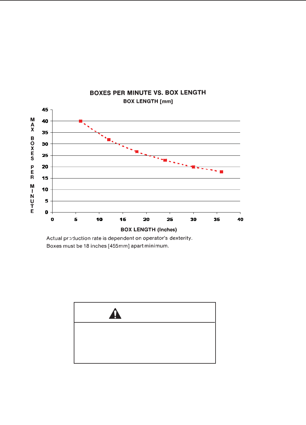
4.2 Operating Rate ............................................................................................................. 12
4.3 Operating Conditions .................................................................................................... 12
4.4 Tape .............................................................................................................................. 12
4.5 Tape Width .................................................................................................................... 12
4.6 Tape Roll Diameter ....................................................................................................... 13
4.7 Tape Application Leg Length - Standard .......................................................................13
Tape Application Leg Length - Optional
4.8 Box Board ..................................................................................................................... 13
4.9 Box Weight and Size Capacities ................................................................................... 13
4.10 Machine Noise Levels ................................................................................................... 14
4.11 Machine Dimensions ..................................................................................................... 14
4.12 Set-Up Recommendations ............................................................................................ 14
iii 2010 December
800ab-NA

8
THIS PAGE IS BLANK

TABLE OF CONTENTS (continued)
i
5. Shipment, Handling, and Storage
5.1 Packed Machine Shipment and Handling ........................................................................... 15
5.2 Overseas Shipment Packaging (Optional) .......................................................................... 15
5.3 Handling and Transportation of Uncrated Machine ............................................................. 15
5.4 Machine Storage ................................................................................................................. 15
6. Unpacking
6.1 Uncrating ............................................................................................................................. 16
6.2 Packaging Materials Disposal ............................................................................................. 16
7. Installation
7.1 Operating Conditions .......................................................................................................... 17
7.2 Space Requirements for Machine Operation and Maintenance ......................................... 17
7.3 Tool Kit Supplied with the Machine ..................................................................................... 17
7.4 Machine Positioning / Machine Set-Up ................................................................................ 17
7.5 Plastic Ties Removal ........................................................................................................... 18
7.6 Assembly Completion .......................................................................................................... 18
7.7 Taping Heads Completion ................................................................................................... 19
7.8 Outboard Tape Roll Holder ................................................................................................. 19
7.9 Preliminary Electric Inspection ............................................................................................ 19
7.10 Main Power Machine Connection and Inspection .............................................................. 19
7.11 Phases Inspection ............................................................................................................... 19
8. Theory of Operation
8.1 Working Cycle Description .................................................................................................. 20
8.2 Running Mode Defi nition ..................................................................................................... 20
8.3.1 Normal Stop Procedure .............................................................................................20
8.3.2 Emergency Stop ....................................................................................................... 20
9. Controls
9.1 Box Width Adjusting Knobs ................................................................................................. 21
9.2 Start / Stop Main Switch........................................................................................................ 21
9.3 Emergency Stop Button (Latching) ...................................................................................... 21
10. Safety devices
10.1 Blade Guards ..................................................................................................................... 22
10.2 Emergency Stop Button ..................................................................................................... 22
10.3 Electric System / Circuit Breaker ......................................................................................... 22
11. Set-Up and Adjustments
11.1 Box Width Adjustment ........................................................................................................ 23
11.2
Box Height Adjustment ....................................................................................................... 23
11.3 Top Flap Compression Roller Adjustment .......................................................................... 23
11.4 Changing the Tape Leg Length .......................................................................................... 23
11.5 Run Boxes to Check Adjustment ........................................................................................ 23
iv
800ab-NA 2010 December
THIS PAGE IS BLANK

11
12. Operation
12.1 Operator’s Correct Working Position .............................................................................. 24
12.2 Starting the Machine ....................................................................................................... 24
12.3 Starting Production ......................................................................................................... 24
12.4 Tape Replacement .......................................................................................................... 24
12.5 Box Size Adjustment ....................................................................................................... 24
12.6 Cleaning ......................................................................................................................... 24
12.7 Table of Adjustments ...................................................................................................... 24
12.8 Safety Devices Inspection .............................................................................................. 24
12.9 Trouble Shooting ............................................................................................................ 25
13. Maintenance
13.1 Safety Measures (see section 3) .................................................................................... 27
13.2 Tools and Spare Parts Supplied with Machine ............................................................... 27
13.3 Maintenance Operations - Recommended Inspections and Frequency .......................... 27
13.4 Inspections to be Performed Before and After Every Maintenance Operation ................ 27
13.5 Safety Features (Inspection Effi ciency) .......................................................................... 27
13.6 Machine Cleaning ........................................................................................................... 27
13.7 Cutter Blade Cleaning .................................................................................................... 27
13.8 Drive Belt Replacement .................................................................................................. 28 - 29
13.9 Drive Pulley Ring ............................................................................................................ 29
13.10 Drive Belt Tension ........................................................................................................... 30
13.11. Special Set-Up Procedures ............................................................................................ 31 - 34
13.11.1 Taping Heads ..................................................................................................... 31
13.11.2 Drive Belt Assembly Height ............................................................................... 32
13.11.3 Chain Removal .................................................................................................. 33
13.12 Maintenance Work Log ................................................................................................... 35
14. Additional Instructions
14.1 Machine Disposal Information ........................................................................................ 37
14.2 Fire emergency ...............................................................................................................
37
15. Enclosures and Special Information
15.1 Statement of Conformity ................................................................................................. 37
15.2 Hazardous Substances Emission ................................................................................... 37
16. Technical Documentation and Information
16.1 Electric Diagrams ........................................................................................................... 39
16.2 Spare Parts / Ordering / Options and Accessories .......................................................... 40 - 41
Drawings and Parts Lists ....................................................................................................... 43 - End of Manual
TAPING HEAD INFORMATION -
MANUAL 2: AccuGlide™ 3 Taping Heads - 2 inch (See MANUAL 2 for Table of Contents)
TABLE OF CONTENTS (continued)
v
800ab-NA 2010 December

ABBREVIATIONS AND ACRONYMS
LIST OF ABBREVIATIONS, ACRONYMS
3M-Matic - Trademark of 3M St. Paul, MN 55144- 1000
AccuGlide - Trademark of 3M St. Paul, MN 55144-1000
Scotch - Trademark of 3M St. Paul, MN 55144-1000
Drw. - drawing
Ex. - for example
Fig. - exploded view fi gure no. (spare parts)
Figure - Illustration
Max. - maximum
Min. - minimum
Nr. - number
N/A - not applicable
OFF - machine not operating
ON - machine operating
PLC - Programmable Logic Control
PP - Polypropylene
PTFE - Polytetrafl ourethelene
PU/PU Foam - Polyurethane Foam
PVC - Poly-vinyl chloride
W - Width
H - Height
L - Length
800ab-NA 2010 December
vi
1-INTRODUCTION
1
1.1 Manufacturing Specif cations / Description / Intended Use
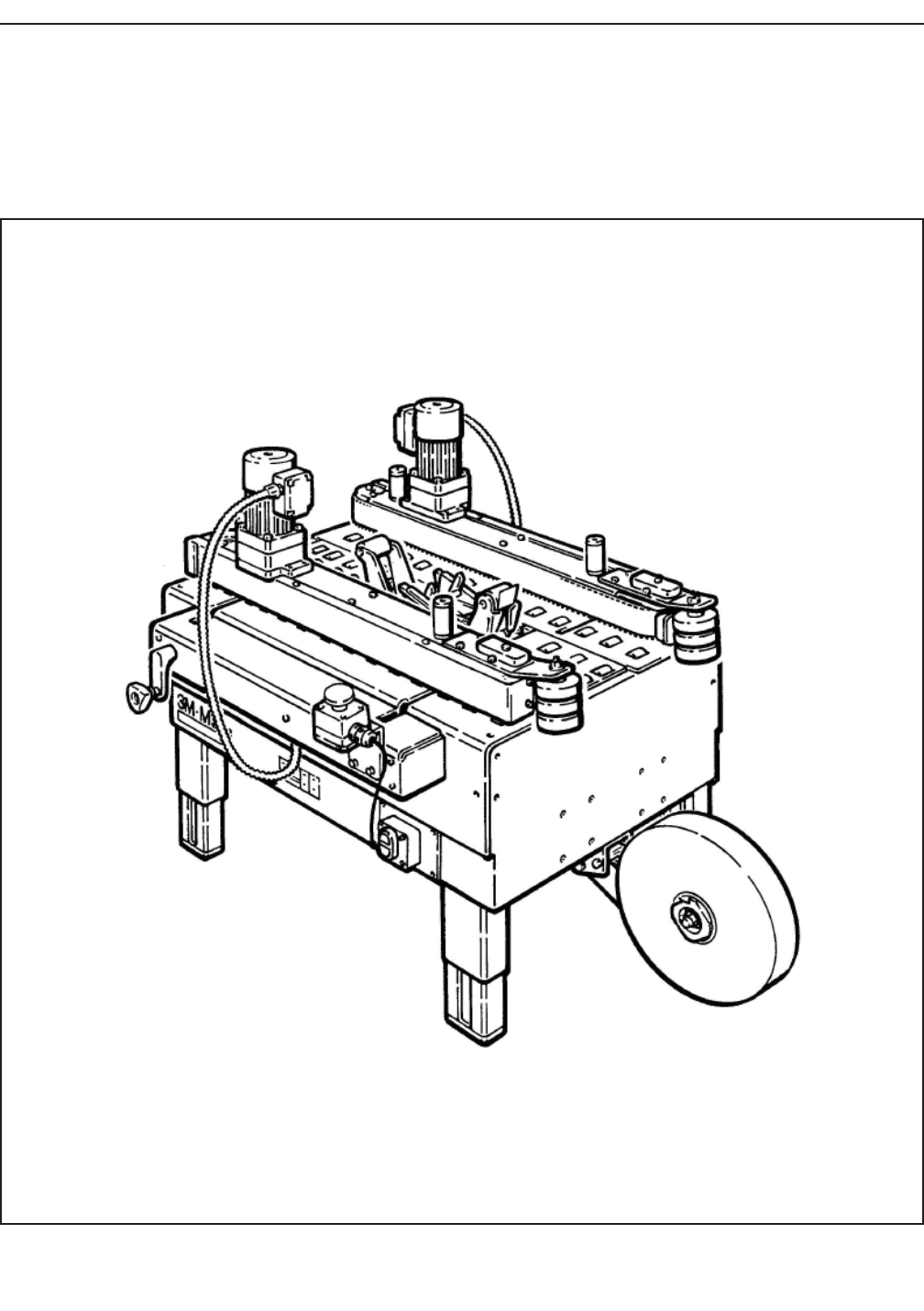
The 3M-MaticTM 800ab Adjustable Case Sealer with AccuGlideTM 3 Taping Heads is designed to apply a “C” clip
of Scotch® pressure-sensitive fi lm box sealing tape to the bottom center seam of regular slotted containers. The
800ab is manually adjustable to a wide range of box sizes (see "Specifi cations Section – Box Weight and Size
Capacities").
3M-MaticTM 800ab Adjustable Case Sealer, Type 40800
Note – Shown above is the lower tape supply roll and bracket assembly in the alternate location.
800ab-NA 2010 December

2
1-INTRODUCTION (continued)
2010 December
800ab-NA
1.2.2 Manual Maintenance
Keep the manual in a clean and dry place near the
machine. Do not remove, tear, or rewrite parts of
the manual for any reason. Use the manual without
damaging it. In case the manual has been lost or
damaged, ask your after sale service for a new copy.
1.2.3 Consulting the Manual
The manual is composed of:
- Pages which identify the document and the machine
- Index of the subjects
- Instructions and notes on the machine
- Enclosures, drawings and diagrams
- Spare parts (last section)
All pages and diagrams are numbered. The spare
parts lists are identifi ed by the fi gure identifi cation
number. All the notes on safety measures or
possible dangers are identifi ed by the symbol:
1.2.4 How to Update the Manual in Case of
Modi f cations to the Machine
Modifi cations to the machine are subject to manu-
facturer’s internal procedures. The user receives a
complete and up-to-date copy of the manual to-
gether with the machine. Afterwards the user may
receive pages or parts of the manual which contain
amendments or improvements made after its fi rst
publication. The user must use them to update this
manual.
1.1 Manufacturing Specif cations / Description /
Intended Use (continued)
The 3M-MaticTM case sealing machines have been
designed and manufactured in compliance with the
legal requirements at the date of inception.
1.2 How to Read and Use the Instruction Manual
This instruction manual covers safety aspects,
handling and transport, storage, unpacking, prepara-
tion, installation, operation, set-up and adjustments,
technical and manufacturing specifi cations, mainte-
nance, troubleshooting, repair work and servicing,
electric diagrams, warranty information, disposal
(ELV), a defi nition of symbols, plus a parts list of
the 3M-MaticTM 800ab Adjustable case sealer 3M
Industrial Adhesives and Tapes Division 3M Center,
Bldg. 220-5E-06 St. Paul, MN 55144-1000 (USA)
Edition December 2010 Copyright 3M 2010 All rights
reserved. .The manufacturer reserves the right to
change the product at any time without notice Publi-
cation © 3M 2010 44-0009-2082-5.
1.2.1 Importance of the Manual
The manual is an important part of the machine; all
information contained herein is intended to enable
the equipment to be maintained in perfect condition
and operated safely. Ensure that the manual is avail-
able to all operators of this equipment and is kept
up to date with all subsequent amendments. Should
the equipment be sold or disposed of, please ensure
that the manual is passed on. Electrical and pneu-
matic diagrams are included in the manual. Equip-
ment using PLC controls and/or electronic compo-
nents will include relevant schematics or programs in
the enclosure and in addition, the relevant documen-
tation will be delivered separately.
2-GENERAL INFORMATION
3
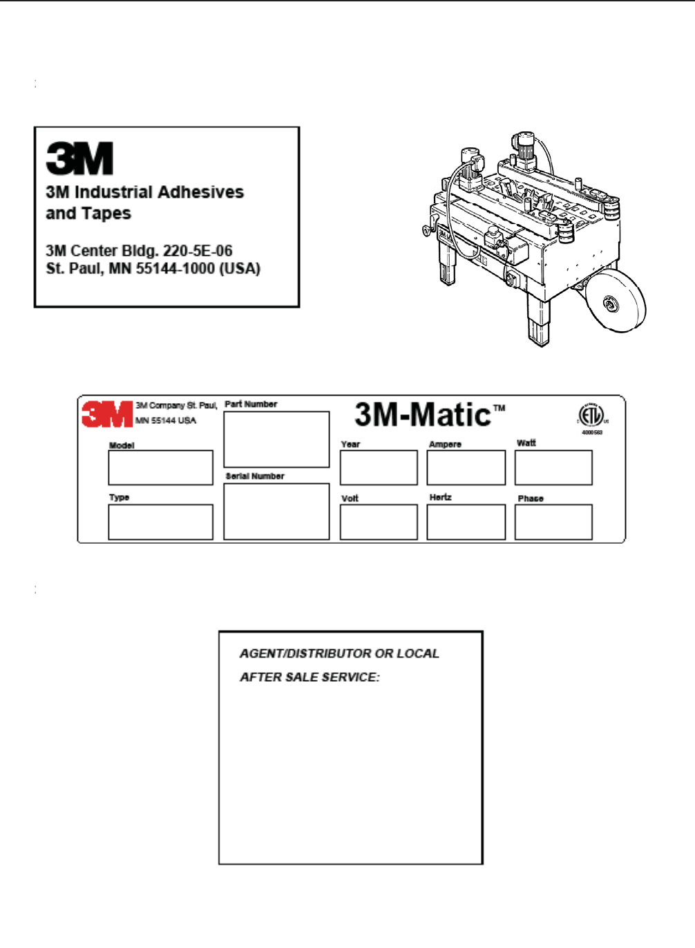
2.1 Data Identifying Manufacturer and Machine
2.2 Data for Technical Assistance and Service
2010 December
800ab-NA

4
2-GENERAL INFORMATION (continued)
2.3 Warranty
Equipment Warranty and Limited Remedy: THE FOLLOWING WARRANTY IS MADE IN LIEU OF ALL
OTHER WARRANTIES, EXPRESS OR IMPLIED, INCLUDING, BUT NOT LIMITED TO, THE IMPLIED
WARRANTY OF MERCHANTABILITY, THE IMPLIED WARRANTY OF FITNESS FOR A PARTICULAR
PURPOSE AND ANY IMPLIED WARRANTY ARISING OUT OF A COURSE OF DEALING, A CUSTOM OR
USAGE OF TRADE:
3M sells its 3M-Matic™ 800ab Adjustable Case Sealer, Type 40800 with the following warranties:
1. The drive belts and the taping head knives, springs and rollers will be free from all defects for ninety (90
days after delivery.
2. All other taping head parts will be free from all defects for three (3) years after delivery.
3. All other parts will be free from all defects for two (2) years after delivery.
If any part is proved to be defective within its warranty period, then the exclusive remedy and 3M’s and seller’s
sole obligation shall be, at 3M’s option, to repair or replace the part, provided the defective part is returned
immediately to 3M’s factory or an authorized service station designated by 3M. A part will be presumed to have
become defective after its warranty period unless the part is received or 3M is notifi ed of the problem no later than
fi ve (5) calendar days after the warranty period. If 3M is unable to repair or replace the part within a reasonable
time, then 3M at its option, will replace the equipment or refund the purchase price. 3M shall have no obligation
to provide or pay for the labor required to install the repaired or replacement part. 3M shall have no obligation
to repair or replace (1) those parts failing due to operator misuse, carelessness, or due to any accidental cause
other than equipment failure, or (2) parts failing due to non-lubrication, inadequate cleaning, improper operating
environment, improper utilities or operator error.
Limitation of Liability: 3M and seller shall not be liable for direct, indirect, special, incidental or consequential
damages based upon breach of warranty, breach of contract, negligence, strict liability or any other legal theory.
The foregoing Equipment Warranty and Limited Remedy and Limitation of Liability may be changed only by a
written agreement signed by authorized offi cers of 3M and seller.
2010 December
Contents—800ab Adjustable Case Sealer
(1) 800ab Adjustable Case Sealer, Type 40800
(1) Tool Kit
(1) Instruction Manual
800ab-NA
5
3-SAFETY
2010 December
800ab-NA
3.1 General Safety Information
Read all the instructions carefully before starting
work with the machine; please pay particular atten-
tion to sections marked by the symbol:
The machine is provided with a LATCHING EMER-
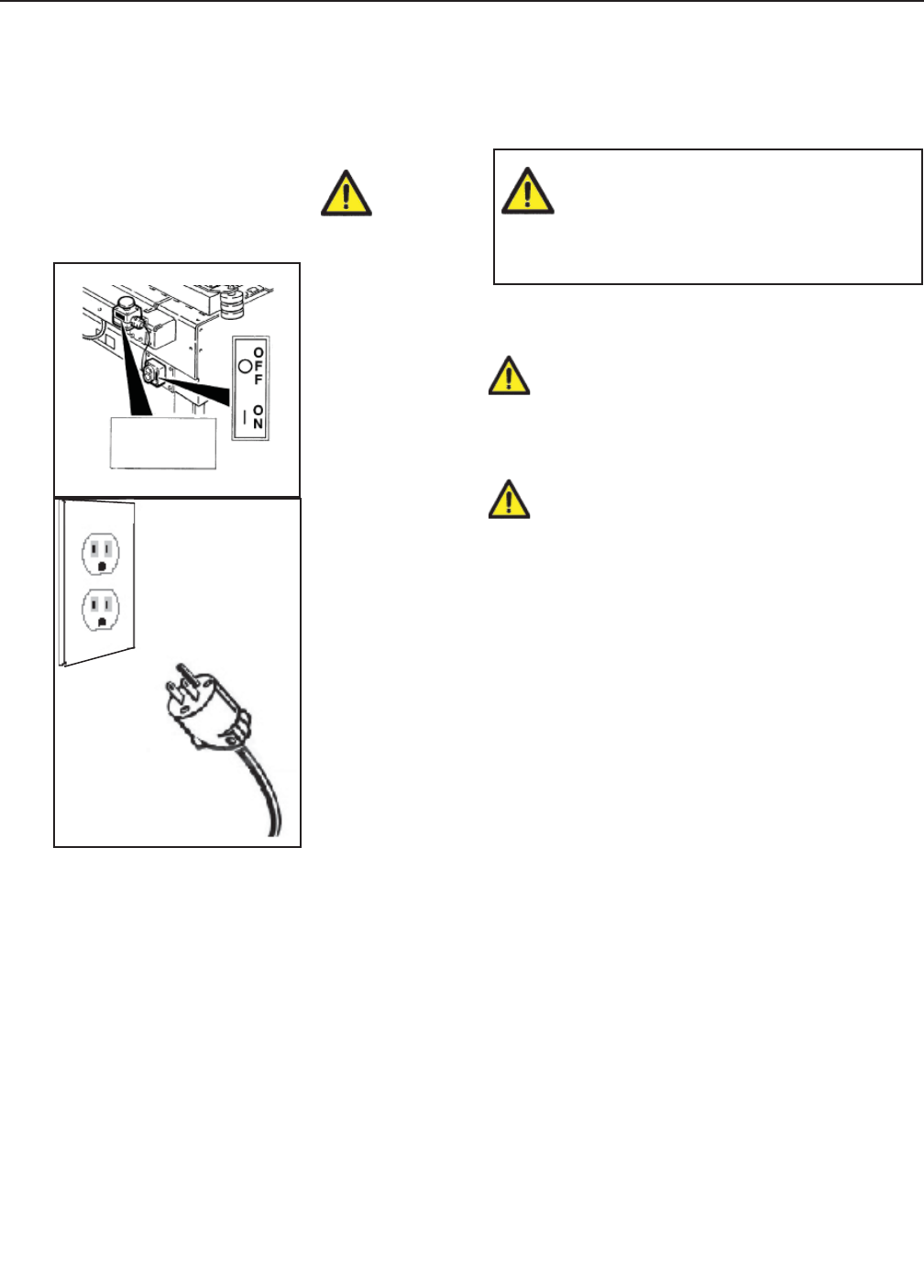
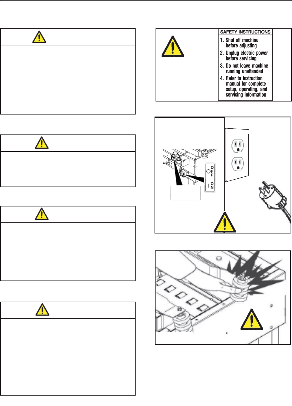
GENCY STOP BUTTON (Figure 3-1); when this
button is pressed, it stops the machine at any point
in the working cycle. Maintain clear access to power
cord while machine is operating. Disconnect plug
from power source before machine maintenance
(Figure 3-1). Also disconnect air if the machine has
a pneumatic system. Keep this manual in a handy
place near the machine. This manual contains infor-
mation that will help you to maintain the machine in
a good and safe working condition.
3.2 Explanation of Signal Word and
Possible Consequences
Indicates a potentially hazardous
situation, which, if not avoided,
may result in minor or moderate
injury and/or property damage.
CAUTION:
Indicates a potentially hazardous
situation, which, if not avoided,
could result in death or serious
injury and/or property damage.
WARNING:
This safety alert symbol identif es
important messages in this manual.
READ AND UNDERSTAND THEM
BEFORE INSTALLING OR
OPERATING THIS EQUIPMENT.
E-Stop
Switch
Figure 3-1
6
3.3 Table of Warnings
• To reduce the risk associated with
mechanical and electrical hazards:
− Read, understand, and follow all safety
and operating instructions before operating
or servicing the case sealer.
− Allow only properly trained and
qualifi ed personnel to operate and service
this equipment.
WARNING
• To reduce the risk associated with
hazardous voltage:
− Position electrical cord away from foot
and vehicle traffi c.
WARNING
• To reduce the risk associated with
pinches, entanglement and
hazardous voltage:
− Turn electrical supply off and
disconnect before performing any
adjustments, maintenance or servicing
the machine or taping heads.
WARNING
• To reduce the risk associated with
pinches and entanglement hazards:
− Do not leave the machine running
while unattended.
− Turn the machine off when not in use.
− Never attempt to work on any part of
the machine, load tape, or remove
jammed boxes from the machine while
the machine is running.
WARNING
3-SAFETY (continued)
2010 December
800ab-NA
Figure 3-2
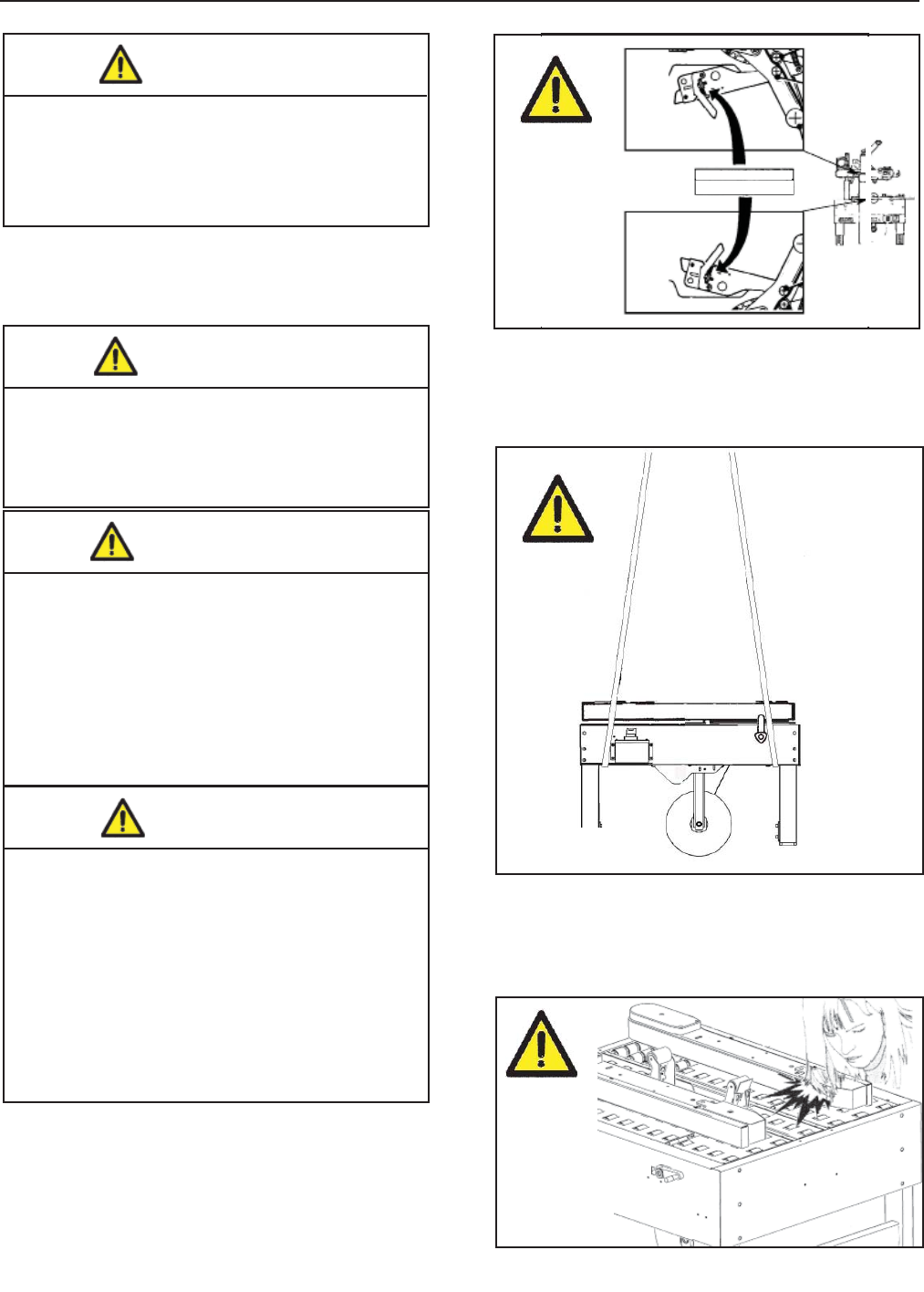
IMPORTANT! Cavity in the conveyor bed. Never put
your hands inside any part of the machine while it is
working. Serious injury may occur (Figure 3-4).
E-Stop
Switch
Figure 3-3
Figure 3-4
7
3-SAFETY (continued)
2010 December
800ab-NA
• To reduce the risk associated with
sharp blade hazards:
− Keep hands and fi ngers away from
tape cutoff blades under orange blade
guards. The blades are extremely sharp.
WARNING
IMPORTANT! Tape cutting blade. Never remove
the safety device which covers the blade on the top
and bottom taping units. Blades are extremely sharp.
Any error may cause serious injuries (Figure 3-5).
• To reduce the risk associated with
pinches hazards:
− Keep hands clear of the upper head
support assembly as boxes are
transported through the machine.
− Keep hands, hair, loose clothing, and
jewelry away from box compression rollers.
− Always feed boxes into the machine by
pushing only from the end of the box.
− Keep hands, hair, loose clothing, jewelry
away from moving belts and taping heads.
CAUTION
• To reduce the risk associated with
f re and explosion hazards:
− Do not operate this equipment
in potentially fl ammable/explosive
environments.
WARNING
• To reduce the risk associated with
muscle strain:
− Use the appropriate rigging and
material handling equipment when
lifting or repositioning this equipment.
− Use proper body mechanics when
removing or installing taping heads
that are moderately heavy or may be
considered awkward to lift.
WARNING
IMPORTANT! Never keep hands on the box while it
is driven by the belts (Figure 3-6).
IMPORTANT! Drive belts. Never work on the
machine with loose hair or loose garments such as
scarfs, ties or sleeves (Figure 3-7).
WARNING
Sharp Blade
Figure 3-7
Figure 3-5
Figure 3-6

8
3-SAFETY (continued)
3.7 Residual Hazards
The case sealer 800ab has been designed follow-
ing the CE 392 directives, and incorporates various
safety protections which should never be removed
or disabled. Notwithstanding the safety precautions
conceived by the designers of the machine, it is
essential that the operator and service personnel
be warned that the following residual hazards exist
which cannot be eliminated.
2010 December
800ab-NA
3.8 Recommendations and Measures to Prevent
Other Hazards which Cannot be Eliminated
- The operator must stay on the working position
shown in the Operation Section. He must never
touch the running driving belts or put his hands
inside any cavity.
- The operator must pay attention to the blades
during the tape replacement.
3.10 Predictable Actions which are Incorrect and
Not Allowed
- Never try to stop/hold the box while being driven
by the belts. Only use the EMERGENCY
STOP BUTTON.
- Never work without the safety protections.
- Never remove or disable the safety devices.
- Only authorized personnel should be allowed
to carry out the adjustments, repairs or main-
tenance which require operation with reduced
safety protections. During such operations,
access to the machine must be restricted.
When the work is fi nished, the safety protec-
tions must immediately be reactivated.
- The cleaning and maintenance operations must be
performed after disconnecting the electric power.
- Do not modify the machine or any part of it. The man-
ufacturer will not be responsible for any modifi cations.
- Clean the machine using only dry cloths or
light detergents. Do not use solvents, petrols, etc.
- Install the machine following the suggested layouts
and drawings. The manufacturer will not be respon-
sible for damages caused by improper installation.
3.4 Operator's Qualif cations
- Machine Operator
- Mechanical Maintenance Technician
- Electrical Maintenance Technician
- Manufacturer’s Technician/Specialist
(See Section 3.11)
3.5 Number of Operators
The operations described below have been analyzed
by the manufacturer; the recommended number of
operators for each operation provides the best and
safest work performance.
Note: A smaller or greater number of operators
could be unsafe.
3.6 Instructions for a Safe Use of the Machine /
De f nition of Operator's Qualif cations
Only persons who have the skills described in the
skill levels section should be allowed to work on the
machine. It is the responsibility of the user to appoint
the operators having the appropriate skill level and
the appropriate training for each category of job.
3.9 Personal Safety Measures
Safety glasses, safety gloves, safety helmet, safety
shoes, air fi lters, ear muffs - None is required except
when recommended by the user.
• To reduce the risk associated with
mechanical and electrical hazards:
− Read, understand, and follow all safety
and operating instructions before operating
or servicing the case sealer.
− Allow only properly trained and
qualifi ed personnel to operate and service
this equipment.
WARNING

9
3-SAFETY (continued)
2010 December
800ab-NA
Operator's Skill Levels Required to Perform the Main Operations on Machine
Skill 1: Machine Operator
This operator is trained to use the machine with the
machine controls, to feed cases into the machine,
make adjustments for different case sizes, to change
the tape and to start, stop and restart production.
Skill 2: Mechanical Maintenance Technician
This operator is trained to use the machine as the
MACHINE OPERATOR and in addition is able to:
• Work with the safety protection disconnected
• Check and adjust mechanical parts
• Carry out machine maintenance operations/repairs
He is not allowed to work on live electrical components
Skill 2a: Electrical Maintenance Technician
This operator is trained to use the machine as the
MACHINE OPERATOR and in addition is able to:
• Work with the safety protection disconnected
• Check and adjust mechanical parts
• Carry out machine maintenance operations / re-
pairs / adjustments / repair electrical components
He is allowed to work on live electrical panels,
connector blocks, control equipment, etc.
Skill 3: Specialist from the Manufacturer
Skilled operator sent by the manufacturer or its
agent to perform complex repairs or modifi cations
(on agreement with the customer).
3.11 Operator's Skill Levels Required to Perform
the Main Operations on the Machine
The Table shows the minimum operator's skill for
each machine operation.
Important: The factory manager must ensure that
the operator has been properly trained on all the
machine functions before starting work.
Operation Machine Status
Required
Operator
Skill
Number of
Operators
Machine installation and setup Running with safety
protections disabled
2 and 2a 2
Adjusting box size Stopped by pressing the
EMERGENCY STOP
button
11
Tape replacement Stopped by pressing the
EMERGENCY STOP
button
11
Blade replacement Electric power
disconnected
21
Drive belt replacement Electric power
disconnected
21
Ordinary maintenance Electric power
disconnected
21
Extraordinary mechanical
maintenance
Running with safety
protections disabled
31
Extraordinary electrical
maintenance
Running with safety
protections disabled
2a 1
• To reduce the risk associated with
mechanical and electrical hazards:
− Allow only properly trained and
qualifi ed personnel to operate and service
this equipment.
WARNING
10
3-SAFETY (continued)
2010 December
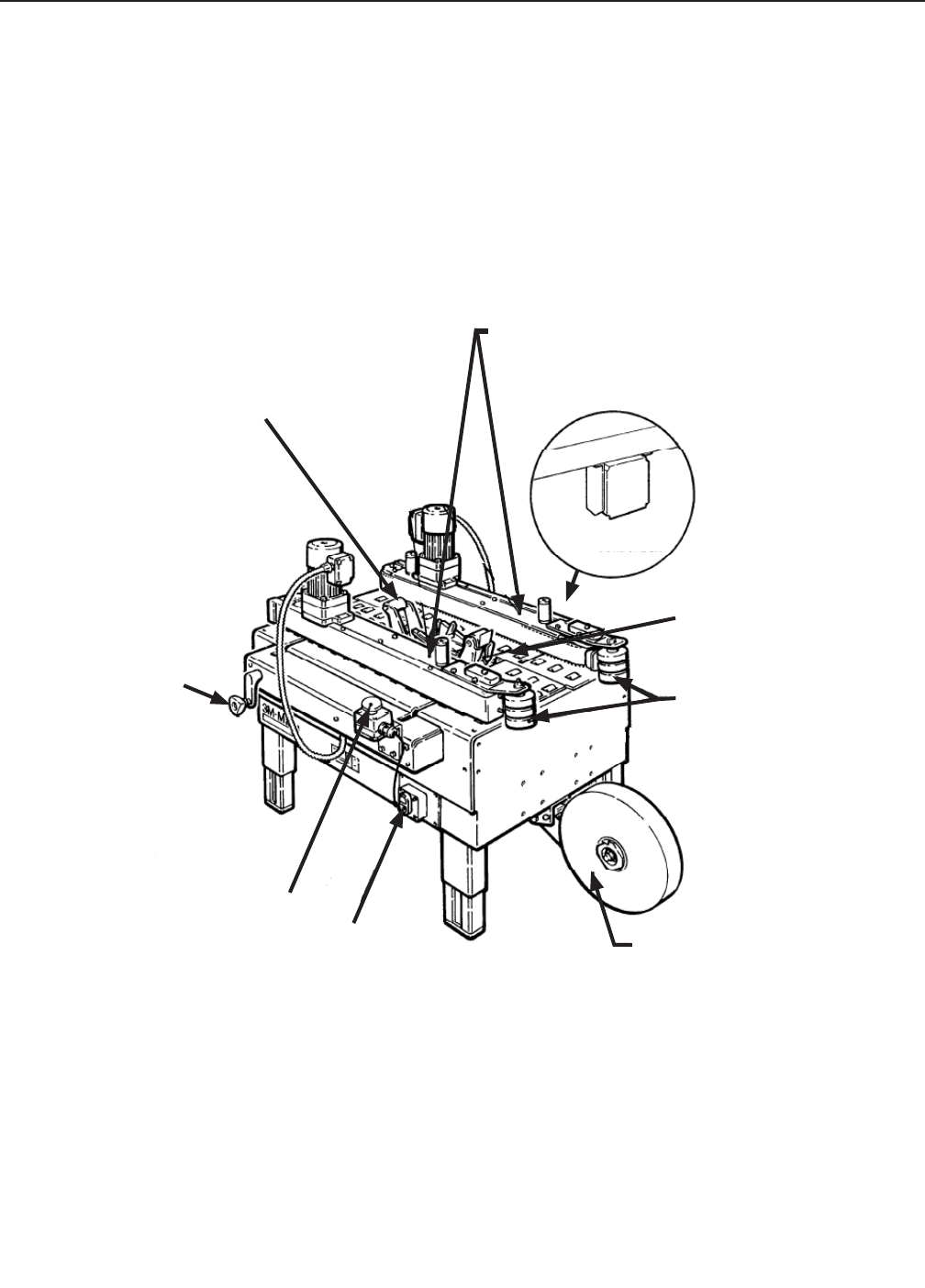
Refer to Figure 3-8 below to acquaint yourself with the various components and controls of the case sealer.
Also refer to Manual 2 for taping head components.
Figure 3-8—800ab Case Sealer Components (Left Front View)
800ab-NA
3.12 Component Locations
Electrical
Control Box
Width
Adjustment
Crank
(Alternate)
Lower Tape
Roll Mount
Inclined Rollers
Adjustable Side
Guides /
Box Drive Belts
Emergency
Stop Button Electrical
On/Off
Switch
Lower Taping Head
Machine Bed
11 2010 December
800ab-NA
3-SAFETY (continued)
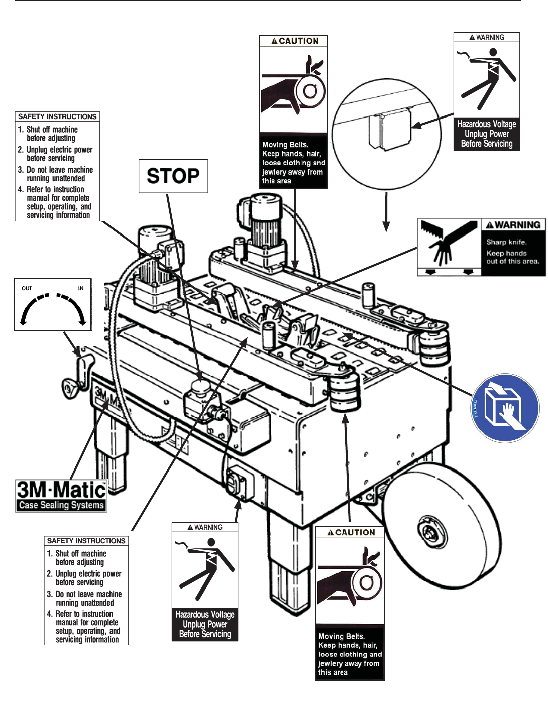
Figure 3-9 - Replacement Labels / 3M Part Numbers
3.13 Table of Warnings and Replacements Labels (continued)
Leg Height Adjustment Label
(not shown)
3M Logo
(not shown)
78-8060-8481-6
78-8070-1339-2
78-8070-1628-8 (2)
78-8062-4266-1
78-8095-1141-9 Electrical
Control
Box
78-8070-1366-5
78-8070-1366-5
78-8113-6717-2
78-8070-1336-8
78-8070-1329-3
78-8070-1329-3
78-8113-6717-2
78-8137-0886-0
12 2010 December
800ab-NA
4-SPECIFICATIONS
1. Power Requirements
Electrical: 120 Volt,60Hz, 3.25 A (220 watts)
The machine is equipped with a 2.4m [8 foot] standard neoprene covered power cord and a grounded plug.
Contact your 3M Representative for power requirements not listed above.
2. Operating Rate
Box drive belt speed is approximately 0.5 m/s [100 feet per minute].
IMPORTANT SAFEGUARD
IMPORTANT SAFEGUARD
5. T ape Width
36mm [1 1/2 inch] minimum to 48mm [2 inch] maximum
4. T ape
Scotch ® pressure-sensitive fi lm box sealing tapes.
3. Operating Conditions
Use in dry, relatively clean environments at 4.4o C to 48.9o C [40o F to 120o F] with clean, dry boxes.
Note: Machine should not be washed or subjected to conditions causing moisture condensation on
components.
• To reduce the risk associated with f re
and explosion hazards:
− Do not operate this equipment in poten-
tially fl ammable or explosive environments.
WARNING

13 2010 December
800ab-NA
4-SPECIFICATIONS (continued)
Specif cations
6. Tape Roll Diameter
Up to 405mm [16 inch] maximum on a 76.2mm [3 inch] diameter core.
(Accommodates all system roll lengths of Scotch® fi lm tapes.)
7. Tape Application Leg Length – Standard
70mm ± 6mm [2.75 inch ±. 25 inch ]
Tape Application Leg Length – Optional
50mm ± 6mm [2 inch ±. 25 inch]
(See "Removing Taping Heads Procedure – Changing the Tape Leg Length")
8. Box Board
Style – regular slotted containers – RSC
125 to 275 P.S.I. bursting test, single wall or double wall B or C fl ute.
23-44 lbs. per inch of width Edge Crush Test (ECT)
9. Box Weight and Size Capacities
A. Box Weight, fi lled: 5 lbs.–85 lbs. [2.3 kg–38.6 kg]. Contents must support fl aps.
B. Box Size: Minimum Maximum
Length – 150mm [6.0 inch] Unlimited
Width – 115mm [4.5 inch] 545mm [21.5 inch]
Height – 120mm [4.75 inch] Limited by stability of box through Case Sealer
Note: The case sealer can accommodate most boxes within the size range listed above. However, if the box
length (in direction of seal) to box height ratio is 0.6 or less, test run several boxes to ensure proper
machine performance.
DETERMINE THE BOX LIMITATIONS BY COMPLETING THIS FORMULA:
BOX LENGTH IN DIRECTION OF SEAL = SHOULD BE GREATER THAN 0.6
BOX HEIGHT
Any box ratio approaching this limitation should be test run to ensure performance.
14 2010 December
800ab-NA
4-SPECIFICATIONS (continued)
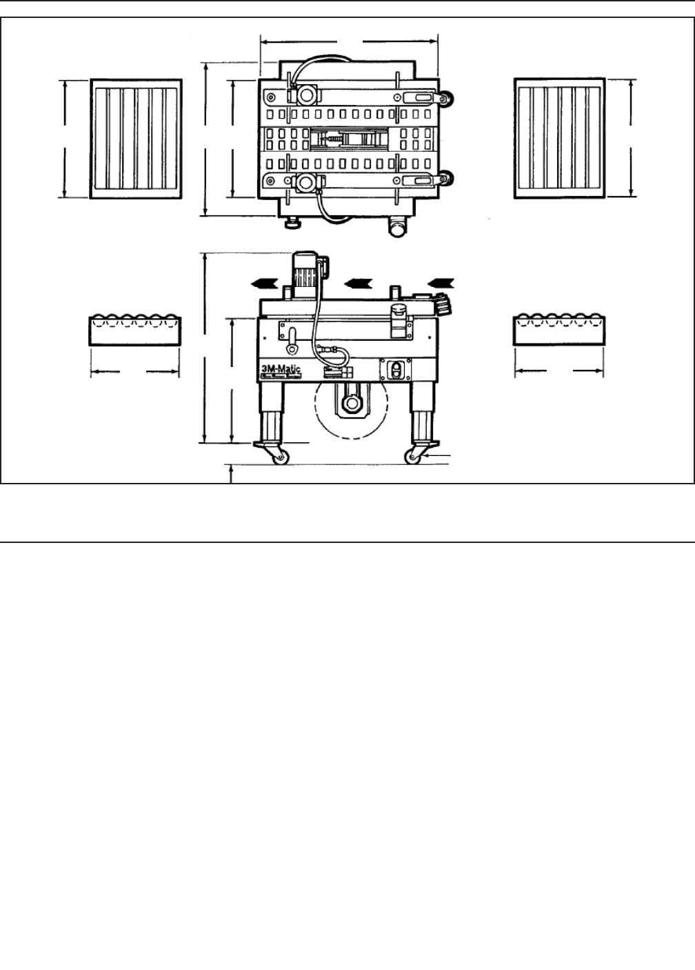
10. Machine Dimensions
W L H A* B C F
Minimum
mm 825 920 940 460 610 105 620
[Inches] [32-1/2] [36-1/4] [37] [18] [24]* [4-3/16] [24.5]
Maximum
mm 1220 [48] * 890
[Inches] - - - - 1270 [50]** - - [35]* - - - -
* With outer columns relocated to upper position, "H" maximum dimension increases 100 mm [4 inches] and
"B" minimum dimension decreases by 90mm [3-1/2 inches]. (See "Special Set-Up Procedure".)
Weight – approximate 132 kg [290 pounds] crated
approximate 114 kg [250 pounds] uncrated
11. Machine Noise Level: Acoustic pressure measured at a distance of 1m. from machine with
Scotch PVC adhesive tape in operation; 78dB Acoustic radiation pressure at 1.6m. height with
Scotch PVC adhesive tape in operation; 73dB Measurement taken with appropriate instrument:
(Type SPYRI-MICROPHON 11).
12. Set-Up Recommendations:
• Machine must be level.
• Customer supplied infeed and exit conveyors (if used) should provide straight and level box entry and exit.
• Exit conveyors (powered or gravity) must convey sealed boxes away from machine.
Optional
Infeed/Exit
Conveyor
Optional
Infeed/Exit
Conveyor
Control
Side
Box Travel
F FW
A A
B
C
L
F
Optional Casters
H
5-SHIPMENT-HANDLING-STORAGE, TRANSPORT
15
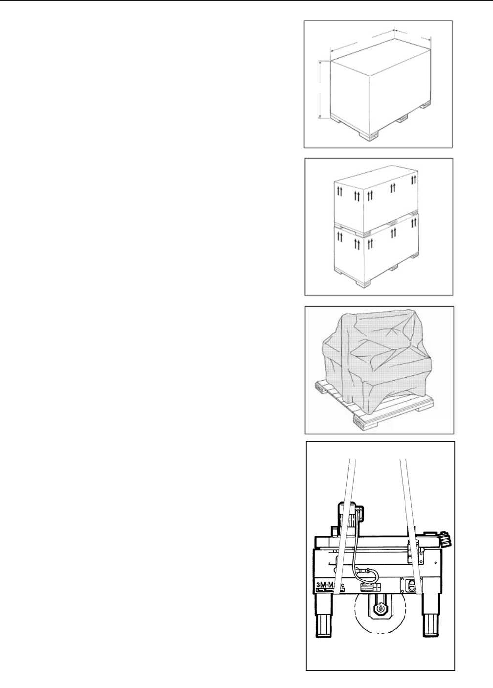
5.1 Shipment and Handling of Packed Machine
- The machine is fi xed on the pallet with four (4) bolts
and can be lifted by using a fork truck.
- The package is suitable to travel by land and by air.
- Optional sea freight package is available.
Packaging Overall Dimensions
(Figure 5-1)
See Specifi cations.
During the shipment it is possible to stack a
maximum of 2 machines (Figure 5-2).
5.2 Packaging for Overseas Shipment
(Optional - Figure 5-3)
The machines shipped by sea freight are covered by
an aluminum/polyester/polythene bag which
contains dehydrating salts.
5.3 Handling and Transportation of Uncrated
Machine
The uncrated machine should not be moved except for
short distances and indoors ONLY. Without the sup-
porting pallet, the machine is exposed to damage and
may cause injuries. To move the machine use belts or
ropes, paying attention to place them in the points in-
dicated using care to not interfere with the lower taping
head (Figure 5-4).
5.4 Storage of the Packed or Unpacked Machine
If the machine is not used for a long period,
please take the following precautions:
- Store the machine in a dry and clean place.
- If the machine is unpacked it is necessary to
protect it from dust.
- Do not stack anything over the machine.
- It is possible to stack a maximum of 2 machines
(if they are in their original packing).
H
LW
Figure 5-1
Figure 5-2
Figure 5-3
Figure 5-4
2010 December
H
LW
800ab-NA
16
6.1 Uncrating
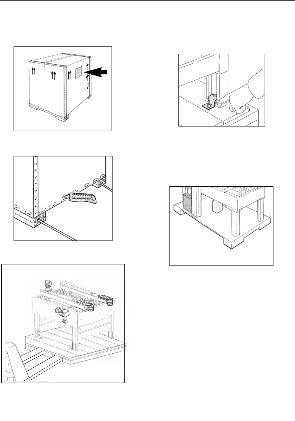
The envelope attached to the shipping box contains
the uncrating instructions of the machine (Figure 6-1).
Cut straps. Cut out staple positions along the bottom
of the shipping box (or remove staples with an
appropriate tool - Figure 6-2).
After cutting out or removing the staples, lift the
shipping box in order to clear the machine
(two persons required).
Transport the machine with a fork-lift truck to the
operating position. Lift the pallet at the point indicat-
ed in Figure 6-3 (weight of machine + pallet = See
Specifi caions).
6.2 Disposal of Packaging Materials
The 800ab-NA package is composed of:
- Wooden pallet
- Cardboard shipping box
- Wooden supports
- Metal fi xing brackets
- PU foam protection
- PP plastic straps
- Dehydrating salts in bag
- Special bag of laminated polyester/aluminium/
Polyethylene (sea freight package only)
- Polyethylene protective material
For the disposal of the above materials, please follow
the environmental directives or the law in your country.
6-UNPACKING
Figure 6-1
Figure 6-2
2010 December
800ab-NA
Figure 6-5
Figure 6-3
Removal of Pallet
Loosen and remove nuts and brackets using the
open end spanner supplied in the tool box (Figure 6-4).
A cardboard box is located under the machine body.
Retrieve the instruction manual for additional proce-
dures of the set up. The box also contains parts re-
moved for shipping, spare parts and tools (Figure 6-5).
Figure 6-4
17 2010 December
800ab-NA
A tool kit containing some tools are supplied
with the machine. These tools should be
adequate to set-up the machine, however,
other tools supplied by the customer will be
required for machine maintenance.
7.3 Tool Kit Supplied with the Machine
7.4 Machine Set-Up / Bed Height
Figure 7-2
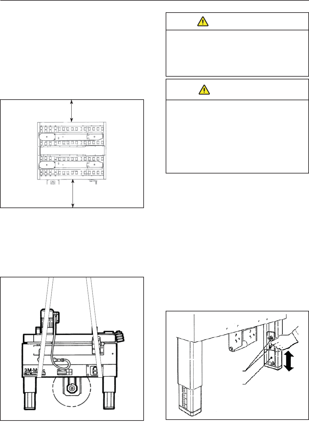
Adjust machine bed height. The case sealer is
equipped with four (4) adjustable legs that are
located at the corners of the machine frame. The
legs can be adjusted to obtain different machine bed
heights from 610mm [24 inches] minimum to 890mm
[35 inches] maximum - See Specifi cations.
Refer to Figure 7-3 and set the machine bed height
as follows:
1. Raise and block up the machine frame to allow
adequate leg adjustment.
2. Loosen, but do not remove, two (2) M8 x 16mm
socket head screws in one leg (use M6 hex
wrench). Adjust the leg length for the desired
machine bed height. Retighten the two screws
to secure the leg. Adjust all four (4) legs equally.
7.1 Operating Conditions
The machine should operate in a dry and relatively
clean environment (See Specifi cations).
7.2 Space Requirements for Machine Operation
and Maintenance Work
Minimum distance from wall (Figure 7-1):
A = 1000mm.
B = 700mm.
Minimum height = 2700mm.
7-INSTALLATION
Figure 7-1
Figure 7-3
M8 x 16mm
Socket Head
Screws
Adjustable
Leg
• To reduce the risk associated with
mechanical and electrical hazards:
− Allow only properly trained and
qualifi ed personnel to operate and service
this equipment.
WARNING
• To reduce the risk associated with
muscle strain:
− Use the appropriate rigging and
material handling equipment when
lifting or repositioning this equipment.
− Use proper body mechanics when
removing or installing taping heads
that are moderately heavy or may be
considered awkward to lift.
WARNING
18
7-INSTALLATION (continued)
2010 December
800ab-NA
7.5 Removal of Plastic Ties 7.6 Assembly Completion
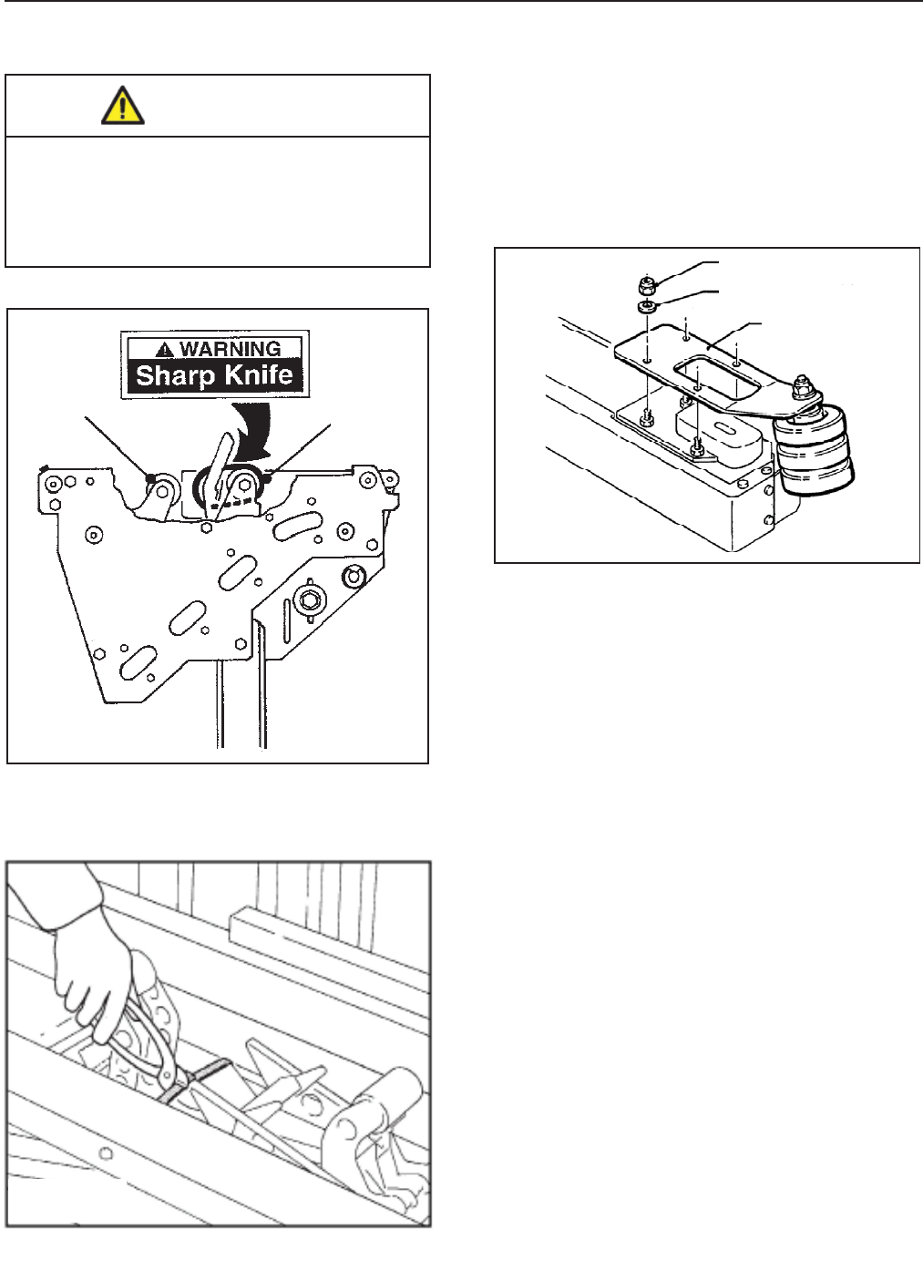
Cut the plastic ties holding the lower taping head in
position (Figure 7-4).
Figure 7-4
Install inclined rollers onto infeed end of each drive belt
assembly. Remove M6 lock nuts (4)and M6 plain wash-
ers (4) from each drive assembly, position inclined roller
on each drive assembly and fasten with M6 plain
washers and M6 locking nuts (See Figure 7-5)
Figure 7-5
• To reduce the risk associated with
sharp blade hazards:
− Keep hands and fi ngers away from
tape cutoff blades under orange blade
guards. The blades are extremely sharp.
WARNING
Inclined Roller
Assembly
M6 Lock Nut (4)
M6 Plain Washer (4)
Cable Tie
Buff ng
Roller
19
7-INSTALLATION (continued)
2010 December
800ab-NA
7.7 Completion of Taping Heads
See Manual 2 for Complete Instructions:
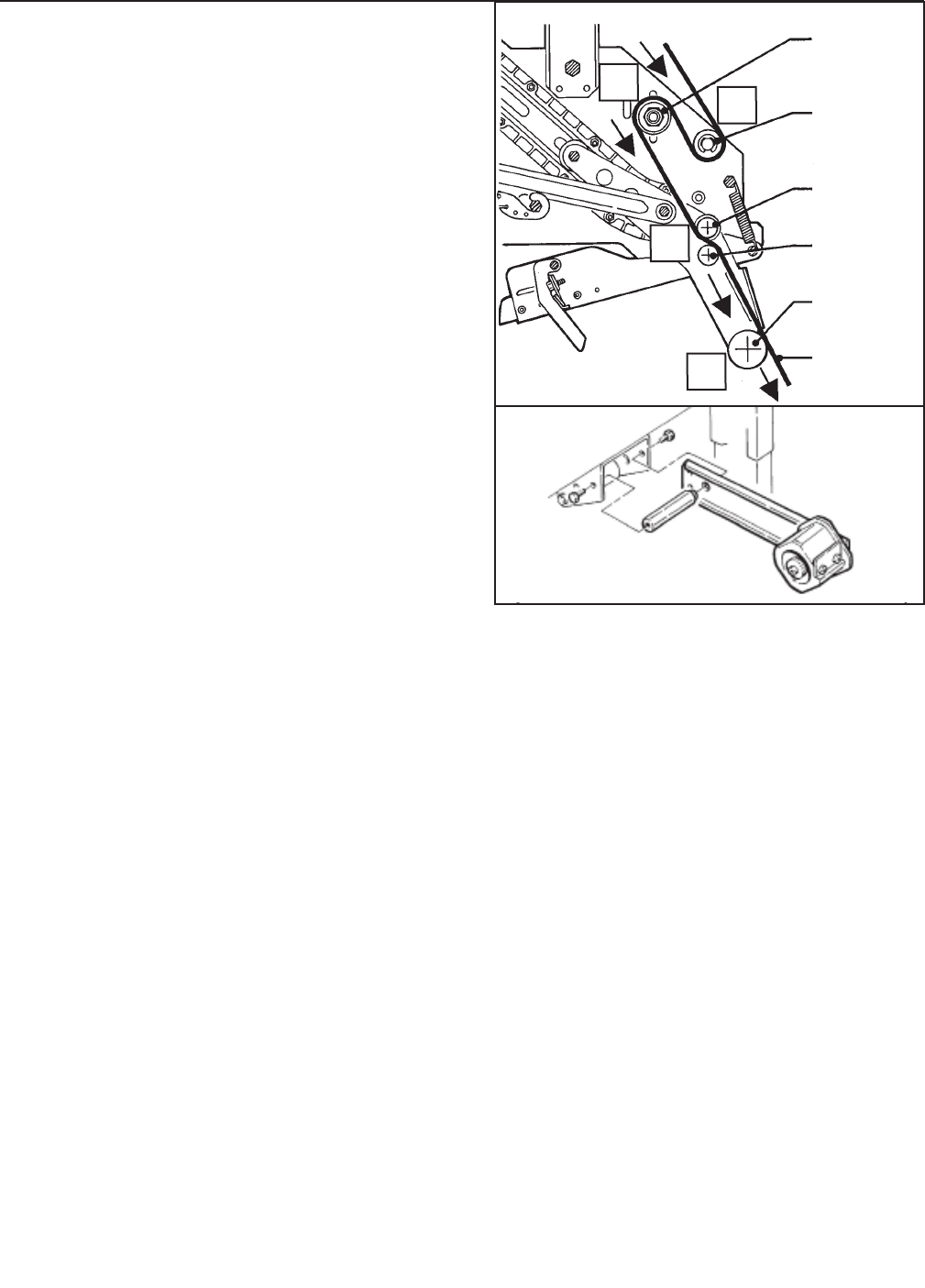
1. Place the Upper Taping Head in a convenient
working position
.2. Use Figure 7-6 and tape threading label.
Position the tape supply roll so the adhesive
side of tape is facing the front of the taping head
as it is pulled from the supply roll.
3. Attach the threading needle to the end of the
roll. Guide the threading needle around the wrap
roller (Position 1) then back around the one-
way tension roller (Position 2).
4. Continue pulling the threading needle down and
guide it between the two (2) rollers on the apply
arm (Position 3).
5. Pull the threading needle down until the tape
travels between the apply plate and the ears of
the apply arm (Position 4) until it extends past
the applying roller. When properly threaded the
adhesive side of the tape should be facing the
knurled rollers at position 2 and also position 3.
6. Cut away any excess tape and repeat steps for
Lower Taping Head.
Important – Do not cut against the apply roller -
roller damage could occur.
7.11 Inspection of Phases
(For Three-Main Phases Only)
N/A for this machine.
7.10 Machine Connection to the Mains
For technical specifi cations: See Section 4 -
Speci f cations
- Push the LATCHING EMERGENCY STOP
BUTTON.
- The main switch is normally OFF.
Connect the power cord supplied with the machine
to a wall socket using a plug which complies with the
safety regulations of your country.
One Way
Tension
Roller
Tension
Wrap
Roller
Knurled
Roller
Wrap
Roller
Applying
Roller
Threading
Needle
#1
#2
#3
#4
Figure 7-6
Figure 7-7
7.8 Outboard Tape Roll Holder
If you intend to use the outboard tape roll holder,
proceed as follows:
1 - Remove the lower taping head from the machine.
2 - Remove the tape drum bracket assembly, stud
spacer, and fasteners from the lower taping head.
3 - Install alternative wrap roller and bracket on the
head in place of tape bracket. Replace lower
head into machine.
4 - Install and secure tape drum bracket assembly
on the entry end of the lower frame (as shown in
Figure 7-7).
7.9 Preliminary Electric Inspection
Before connecting the machine to the mains please
carry out the following operations:
7.9.1 Make sure that the socket is provided with an
earth protection circuit and that both the mains
voltage and the frequency match the specifi -
cations on the name plate.
7.9.2 Check that the connection of the machine
to the mains meets the safety regulations in
your country.
7.9.3 The machine is fi tted with a main switch
and a circuit breaker. The user should check
that the electrical settings of the machine are
compatible with all the components of the
mains system.
20
8.1 Description of the Working Cycle
After having closed the top fl aps of the carton, the
operator pushes it under the top infeed end in order
to avoid the opening of the top fl aps. Further push-
ing causes the two bottom side belts to drive the
box through the taping heads which automatically
seal the top and bottom seams. The carton is then
expelled on the exit conveyor.
8.2 Def nition of Running Mode
The case sealer 800ab-NA has only one (automatic)
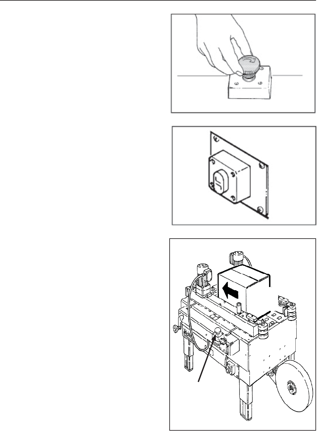
operating mode with:
- The EMERGENCY STOP BUTTON unlocked
(Figure 8-1)
- The main switch start switch “ON”
(Figure 8-2)
8.3.1 Normal Stop Procedure
When the main switch is OFF, the machine stops
immediately at any point of the working cycle. The
same thing happens in case of electrical failure or
when the machine is disconnected from the mains.
8.3.2 Emergency Stop
The LATCHING EMERGENCY STOP BUTTON is
located on the top center of the machine
(Figure 8-1).
8-THEORY OF OPERATION
2010 December
800ab-NA
E-Stop
Location
Belt
Direction
Figure 8-1
Figure 8-2
Figure 8-3

9-CONTROLS
21 2010 December800ab-NA
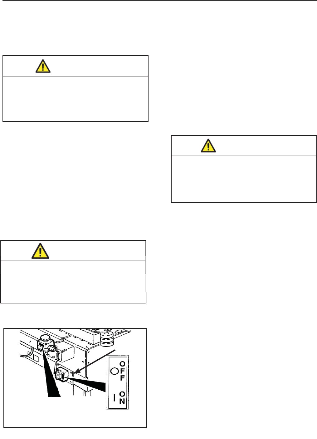
9.1 Box Width Adjusting Knobs
9.2 Start/Stop Button
9.3 Latching Emergency Stop Button
Figure 9-2
Figure 9-1
E-Stop
Switch
Power
Switch
Figure 9-3
10-SAFETY DEVICES OF THE MACHINE
22
E-Stop
Switch
10.1 Blade Guards
Both the top and bottom taping units have a blade
guard. (See Manual 2: AccuGlide™ 3 Taping
Heads - 2 inch).
10.2 Emergency Stop Button
The box drive belts are turned on and off with the
electrical switch on the side of the machine frame.
The machine electrical supply can be turned off
by pressing the latching emergency stop switch.
To restart machine, rotate the emergency stop
switch clockwise to release the switch latch.
Restart machine by Pushing the On/Off switch to
the Off (O) position and then to the On (I) position
(Figure 10-1).
10.3 Electric System / Circuit Breaker
The electric system is protected by a ground wire
whose continuity has been tested during the fi nal
inspection. The system is also subject to insulation
and dielectric strength tests.
2010 December
800ab-NA
• To reduce the risk associated with
hazardous voltage:
− Position electrical cord away from foot
and vehicle traffi c.
WARNING
• To reduce the risk associated with
mechanical and electrical hazards:
− Allow only properly trained and
qualifi ed personnel to operate and service
this equipment.
WARNING
Figure 10-1
The case sealer is equipped with a circuit breaker
which trips if the motors are overloaded. Located
inside the electrical enclosure on the side of the
machine frame just below the machine bed, the
circuit breaker has been pre-set and requires no
further maintenance.
1. Determine cause of overload and correct.
2. Remove electrical enclosure cover.
3. Press the red "Reset" button and then the
green "Start" button.
4. Replace cover.
5. Plug in machine.
6. Press machine "On" button to resume case
sealing.
Circuit Breaker
If circuit is overloaded and circuit breaker trips,
unplug machine from electrical power:
• To reduce the risk associated with
sharp blade hazards:
− Keep hands and fi ngers away from
tape cutoff blades under orange blade
guards. The blades are extremely sharp.
WARNING
Important: The use of an extension cord is not
recommended. However, if one is needed for
temporary use, it must:
• Have a wire size of 1.5mm diameter [AWG 16]
• Have a maximum length of 30.5m [100 ft]
• Be properly grounded.
11 - SET UP AND ADJUSTMENTS
23
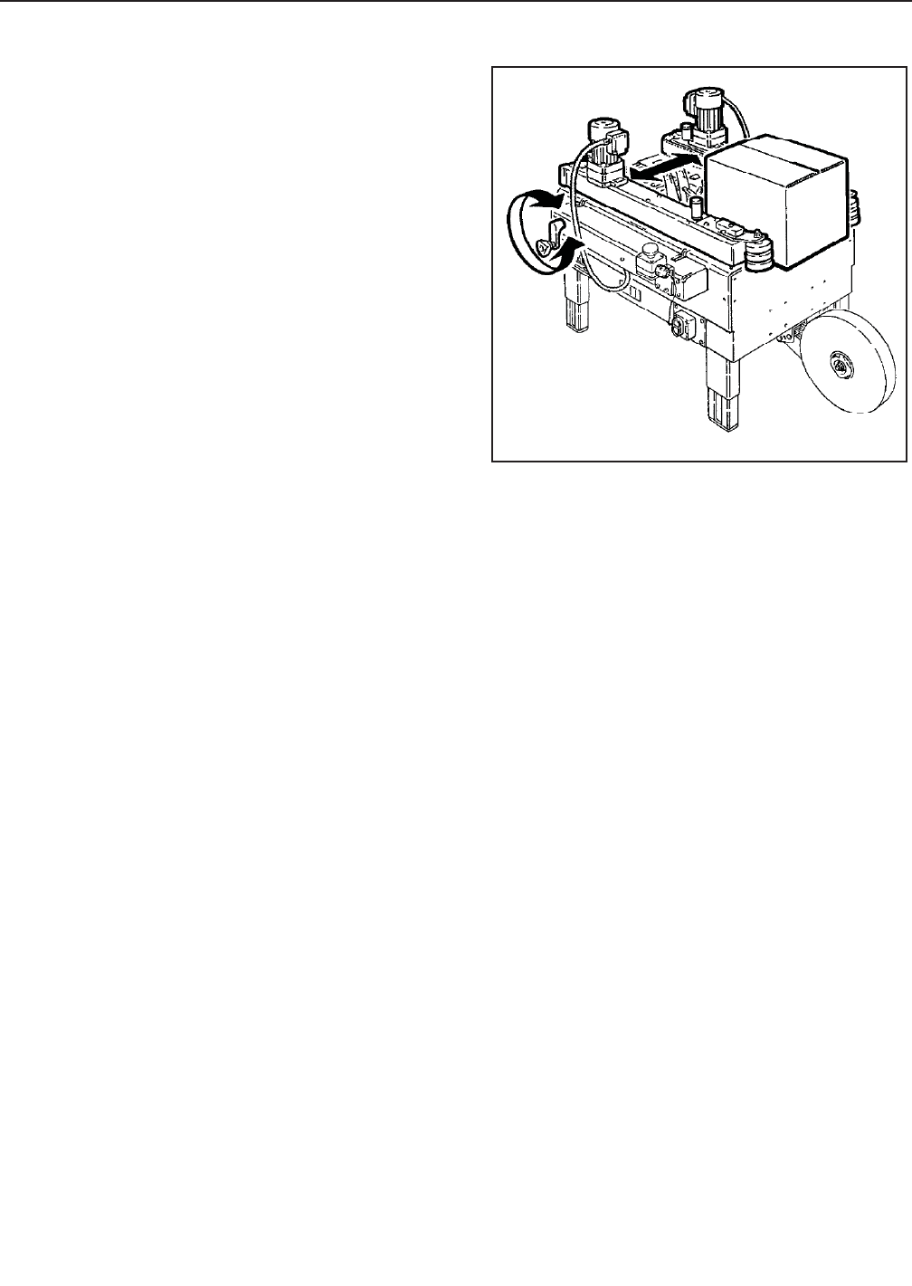
11.1 Box Width Adjustment
Place a product fi lled box on infeed end of machine
bed with top fl aps folded as shown and manually
move box forward to contact lower taping head
applying roller.
Turn drive belt adjustment crank to position both side
drive belts against sides of box (Figure 11-1).
11.2 Box Height Adjustment
Not Applicable to this machine.
11.3 Adjustment of Top Flap Compression Rollers
Not Applicable to this machine.
11.4 Changing the Tape Leg Length
Taping heads are preset to apply 70mm [2.75 inches]
long tape legs. To change tape leg length to 50mm
[2.0 inches], refer to Instructions below and also to
Manual 2, "Removing Taping Heads Procedure -
Changing the Tape Leg Length".
11.5 Run Boxes to Check Adjustment
Push electrical switch "On" to start drive belts.
Move box forward under upper taping head until it
is taken away by drive belts. If box is hard to move
under head or is crushed, raise head slightly.
If the box movement is jerky or stops under the upper
head, move the side drive belts in slightly to add more
pressure between the box and drive belts.
2010 December
800ab-NA
Figure 11-1
IMPORTANT – If drive belts are allowed to slip on
box, excessive belt wear will occur.
24
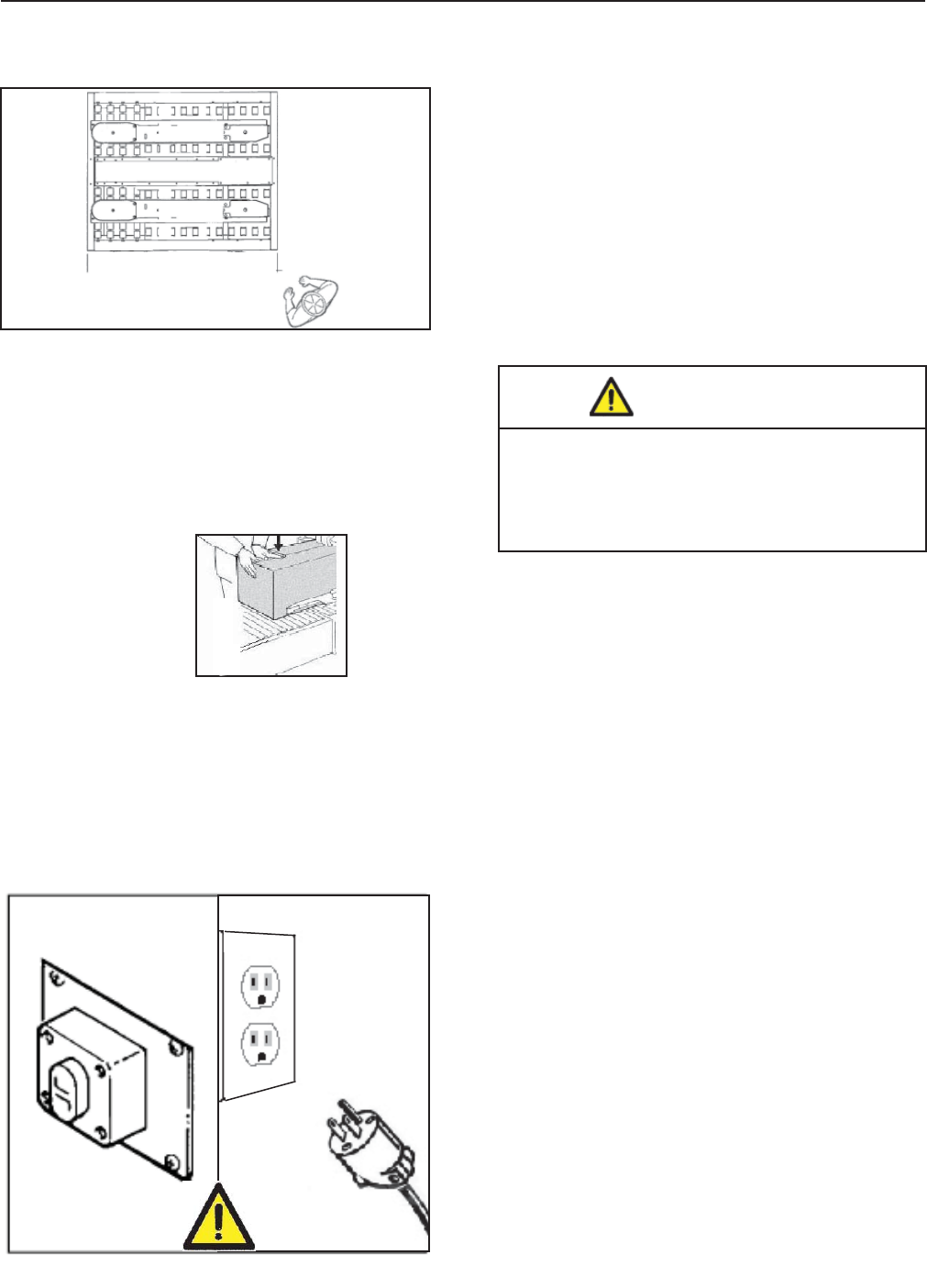
12.1 Operator's Correct Working Position and
Operational Flow (Figure 12-1).
Once the box has been fi lled, close its top fl aps and
push it between the top and bottom drive belts.
Always keep hands in position as shown in
Figure 12-2.
The box will be automatically sealed with adhesive
tape on the top and bottom box seams. Then the
box will be expelled on the exit conveyor.
12-OPERATION
12.3 Starting Production
After having adjusted the machine according to the
box dimensions (height-width), let the machine run
without cartons and check its safety devices. Then
start the working cycle.
12.4 Tape Replacement and Threading
Skill 1 - Operator
See Manual 2: AccuGlide™ 3 High Speed 2 Inch
Taping Heads.
Press the
LATCHING EMERGENCY STOP BUTTON.
12.5 Box Size Adjustment
Repeat all the operations shown in
Section 11 - Set-Up and Adjustments.
12.6 Cleaning
Before carrying out any cleaning or maintenance
operation stop the machine by Pushing the OFF
switch on the main and disconnect the electric power
(Figure 12-3).
12.8 Safety Devices Inspection
1 Taping units blade guard
2 Latching emergency stop button
3 STOP (OFF) main switch
Operator Qualif cations
1 Tape loading and threading 1
2 Tape web alignment 1
3 Adjustment of one way tension roller 1
4 Adjustment to box size (H and W) 1
5 Top fl ap compression rollers 1
6 Adjustment of tape applying spring 1
7 Conveyor bed height adjustment 1
8 Special Adjustment-Changing tape leg length 2
9 Special Adjustment-Column re-positioning 2
12.7 Table of Operation Adjustments -
12.2 Starting the Machine
Important: Before starting the machine, verify that
no tools or other objects are on the conveyor bed.
Push the main switch ON after the EMERGENCY
BUTTON is released.
2010 December
800ab-NA
Figure 12-3
Figure 12-1
• To reduce the risk associated with sharp
blade hazards:
− Keep hands and fi ngers away from tape
cutoff blades under orange blade guards.
The blades are extremely sharp.
WARNING
Hand
Position
Figure 12-2

25
12-OPERATION (continued)
12.9 Troubleshooting Guide
Correction
Check machine specifi cations.
Boxes are narrower than
recommended, causing slippage
and premature belt wear.
Replace drive belts
Adjust the box height adjustment
with the crank
Readjust compression rollers
Replace spring holder
Reduce spring pressure
Replace friction rings
Adjust belt tension
Check power and electrical plug
Evaluate problem and correct
Replace belt
Tension to 3.5 kg [7 lbs] per
adjustment section
Reposition tape drum
Check box specifi cations
Cause
Narrow boxes
Worn drive belts
Top taping head does not apply
enough pressure
Top fl ap compression rollers in too
tight
Taping head applying spring
holder missing
Taping head applying spring set
too high
Worn or missing friction rings
Drive belt tension too low
Electrical disconnect
Motor not turning
Worn belt
Excessive belt tension
Tape drum not centered
Box fl aps not of equal length
Problem
Drive belts do not convey boxes
Drive belts do not turn
Drive belt break
Tape not centered on box seam
2010 December
800ab-NA
26
THIS PAGE IS BLANK
27 2010 December
800ab-NA
13.1 Safety Measures (see section 3)
Carrying out maintenance and repairs may imply
the necessity to work in dangerous situations.
13.2 Tools and Spare Parts Supplied with
the Machine
See Spare Parts Order Section.
13.3 Recommended Frequency of Inspection and Maintenance Operations
Operation Frequency Quali f cation Sections
Inspection safety features daily 1 13.4
Cleaning of machine weekly 1 13.5
Cleaning of cutter blade weekly 2 13.6
Oiling of felt pad weekly 2 13.7
Lubrication monthly 2 13.7-13.8
Blade replacement when worn 2 See Manual 2
Drive belt replacement when worn 2 13.10
13.4 Inspections to be Performed Before and
After Every Maintenance Operation
Before every maintenance operation, Push the main
switch OFF and disconnect. During the maintenance
operation, only properly trained and qualifi ed person-
nel must work on the machine. At the end of every
maintenance operation check the safety devices.
13-MAINTENANCE AND REPAIRS
13.5 Check Eff ciency of Safety Features
1. Blade guard assembly lower taping head
2. Latching Emergency stop button with mechanical
lock (interrupt supply of electrical power)
3. Push the main switch STOP/OFF
13.6 Cleaning of Machine
Qualif cation 1
A weekly cleaning with dry rags or diluted detergents
is necessary. Cardboard boxes produce a signifi cant
quantity of dust and paper chips when processed
or handled in case sealing equipment. If this dust is
allowed to build up on machine components, it can
cause component wear and over-heating of drive
motors. The dust build up is best removed from the
machine with a vacuum cleaner. Depending on the
number of cartons processed, this cleaning should
be done weekly. Excessive build-up that cannot be
removed by vacuuming should be removed with a
damp cloth.
• To reduce the risk associated with
mechanical and electrical hazards:
− Read, understand, and follow all safety
and operating instructions before operating
or servicing the case sealer.
− Allow only properly trained and qualifi ed
personnel to operate and service this
equipment.
• To reduce the risk associated with
pinches, entanglement and hazardous
voltage:
− Turn electrical supply off and disconnect
before performing any adjustments,
maintenance or servicing the machine or
taping heads.
WARNING
13.7 Cleaning of Cutter Blade
Qualif cation 2
Should tape adhesive build-up occur, carefully wipe
clean with oily cloth or brush (Figure 13-1). Oil pre-
vents the build-up of tape adhesive.
(See manual 2.)
13.8 Drive Belt Replacement
Note – 3M recommends the replacement of drive belts in pairs, especially if belts are unevenly worn.
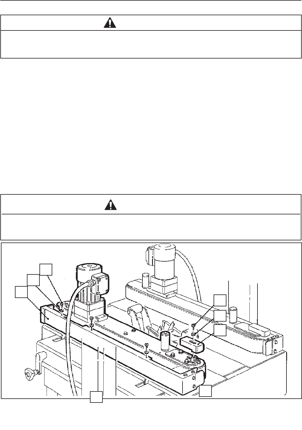
Figure 13-4 – Box Drive Belt (Left Side View – Infeed End)
1. Crank the upper taping head to its fully raised position.
2. Remove and retain the three (3) screws (A), three (3) washers (B) and side cover (C). See Figure 13-4.
3. Remove and retain the screw (D), washer (E) and belt tensioner cover (F).
4. Turn belt adjustment screws (G) counterclockwise on both the upper and lower tension assemblies until belt is
loose. See Figure 13-5.
5. Locate the belt lacing (joint) by turning the belt manually. Remove the pin with pliers. Remove and discard
old belt.
Replacement - See Steps 1 thru 8
Tension Adjustment - See Steps 3, 7 and 9.
• To reduce the risk associated with pinch, entanglement and hazardous voltage:
− Turn electrical supply off and disconnect before performing any adjustments, maintenance or
servicing the machine or taping heads
WARNING
• To reduce the risk associated with mechanical and electrical hazards:
− Allow only properly trained and qualifi ed personnel to operate and/or service this equipment
WARNING
13-MAINTENANCE AND REPAIRS (continued)
28 2010 December
800ab-NA
A
B
C
D
E
F
G
G
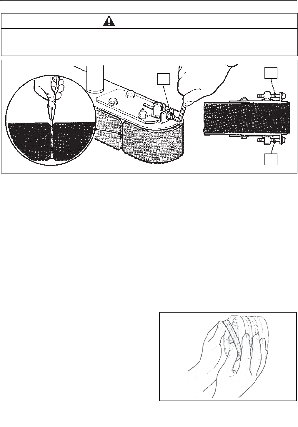
Figure 13-5 – Box Drive Assembly, Infeed End
6. Install the new belt around drive rollers and insert new pin. Pin must not extend beyond edge of belt.
7. To set drive belt tension, turn adjustment screws (G) equally on both the upper and lower tension assemblies.
Turn the screws clockwise to increase tension or counterclockwise to decrease tension. See Figure 13-5.
Use a force gauge to pull the belt outward 25mm [1 inch] at mid span, as shown with a moderate pulling force
of 3.5 kg [7 lbs].
8. Reverse procedures in Steps 1-3 (Figure 13-4) to reassemble the drive belt assembly.
Important – Before installing new drive belt, check the belt inside surface for drive direction arrows and install
belt accordingly. If no arrows are shown, the belt may be installed either way.
13-MAINTENANCE AND REPAIRS (continued)
29
13.9 Drive Pulley Rings Installation :
Before installing a new belt, check the orange plastic
drive pulley rings for wear. If torn, broken, or worn
smooth, replace the rings (Figure 13-6).
Figure 13-6
2010 December
800ab-NA
• To reduce the risk associated with pinch, entanglement and hazardous voltage:
− Turn electrical supply off and disconnect before performing any adjustments, maintenance or
servicing the machine or taping heads
WARNING
G
G
G
13.10 Drive Belt Tension
Tension adjustment of the drive belts may be required during normal operation. Belt tension must be adequate to
positively move the box through the machine and they should run fully on the surface of the pulleys at each end of
the frame. The idler pulleys on the infeed end are adjusted in or out to provide proper belt tension. Each belt is
adjusted separately.
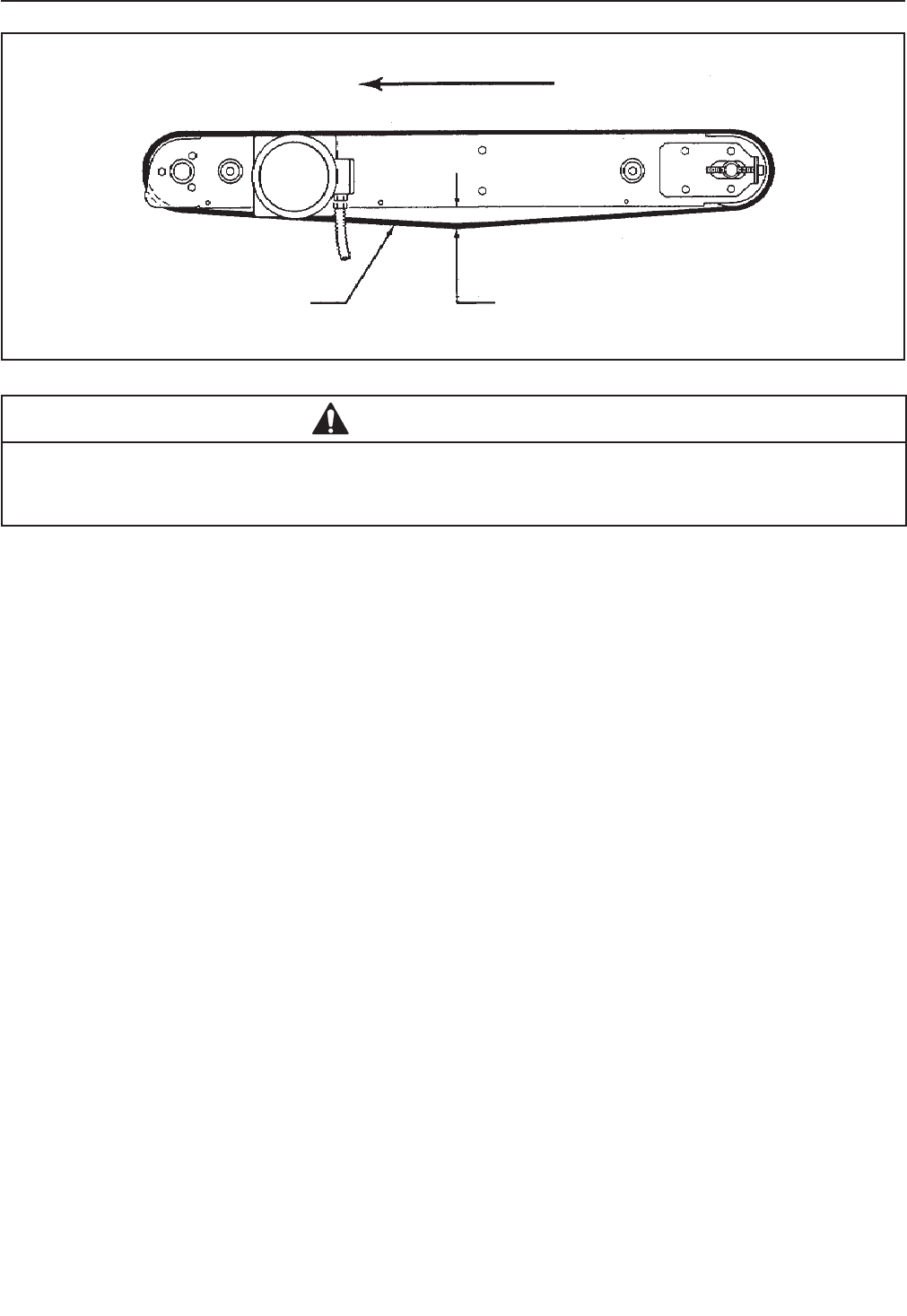
Belt tension is obtained by tightening the adjustment screw so that a moderate pulling force of 3.5 kg [7 lbs]
applied at the midspan, as shown in Figure 13-7, will defl ect the belt 25mm [1 inch]. This will assure positive
contact between the belt and the drive pulley on the discharge end of the taping head.
To adjust belts, see "Maintenance – Drive Belts", steps 3 and 7.
13-MAINTENANCE AND REPAIRS (continued)
30
Figure 13-7 – Box Drive Belt Tension Adjustment, Top View
2010 December
800ab-NA
• To reduce the risk associated with pinch, entanglement and hazardous voltage:
− Turn electrical supply off and disconnect before performing any adjustments, maintenance or
servicing the machine or taping heads
WARNING
Infeed EndDischarge End
Box Drive Belt
Drive Belt
Direction
25mm [2 Inch] Def ection
@ 3.5 kg [7 lbs.] Pull Force at Midspan
13.11.1 Taping Heads
13-MAINTENANCE AND REPAIRS (continued)
31
TAPE WEB ALIGNMENT – Manual 2
TAPE DRUM FRICTION BRAKE – Manual 2
APPLYING MECHANISM SPRING – Manual 2
ONE-WAY TENSION ROLLER – Manual 2
TAPE LEG LENGTH
Leading Tape Leg Length Adjustment – Manual 2
Changing Tape Leg Length from 70 to 48mm [2-3/4 to 2 inches] – Manual 2
Note – Changing tape leg to 48mm [2 inches] requires machine adjustment also. See
"Special Set-Up Procedure – Changing Tape Leg Length".
Taping Head Adjustments
• To reduce the risk associated with sharp blade hazards:
− Keep hands and fi ngers away from tape cutoff blades under orange blade guards. The blades
are extremely sharp
WARNING
13.11 Special Set-Up Procedure
WARNING
2010 December
800ab-NA
• To reduce the risk associated with mechanical and electrical hazards:
− Turn electrical and air supply off and disconnect before performing any adjustments,
maintenance, or servicing the machine or taping heads
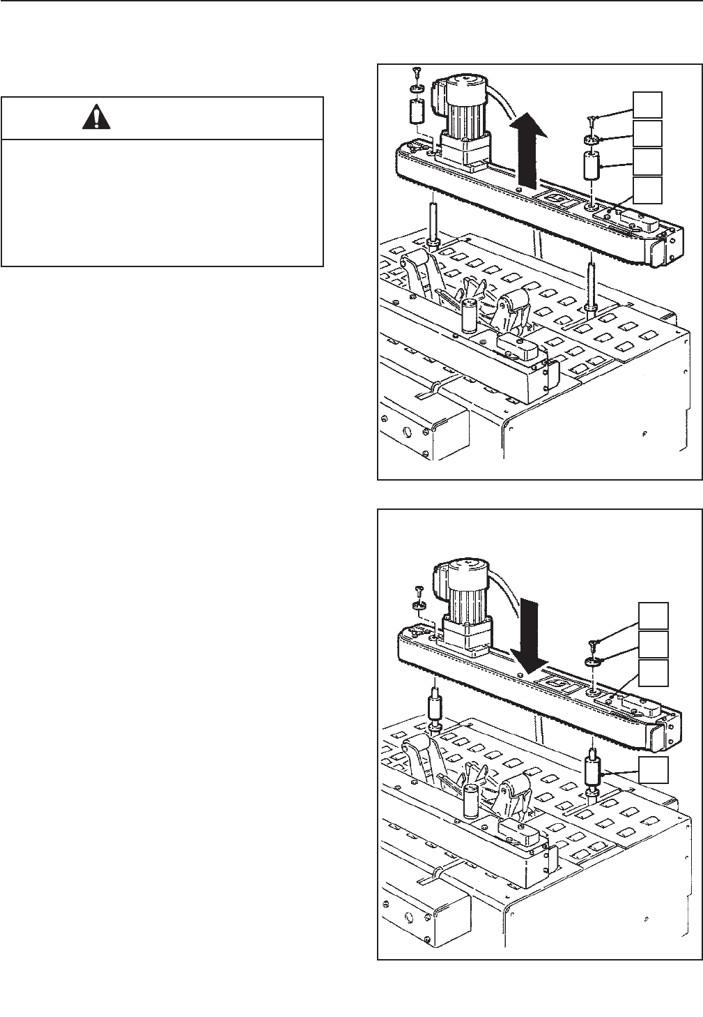
13.11.2 Drive Belt Assembly Height
The drive belt assemblies can be raised 48mm
[2 inches] to provide better conveying of tall boxes.
This change increases the minimum box height that
can be taped to 190mm [7-1/4 inches].
Disassemble – Figure 13-8
1. It is fi rst necessary to raise the top taping head.
Utilize the height adjustment crank and move
the upper taping head to the fully raised position.
2. Remove and retain the screw (A), cap washer
(B) and spacer (C) from the front and rear arm
assembly pivots.
3. Lift belt drive assembly (D) up off the arm
assembly pivots.
Reassemble – Figure 13-9
4. Reassemble the spacer (C) onto the front and
rear arm assembly pivots.
5. Install the belt drive assembly (D) onto the pivots
and secure with the cap washers (B) and screws
(A).
Note – Both drive belt assemblies must be
installed at the same operating height.
Figure 13-8 – Drive Belt Assembly, Disassembly
Figure 13-9 – Drive Belt Assembly, Reassembly
• To reduce the risk associated with
muscle strain:
− Use proper body mechanics when
removing or installing taping heads that
are moderately heavy or may be
considered awkward to lift
WARNING
13-MAINTENANCE AND REPAIRS (continued)
32
Special Set-Up Procedure (continued)
2010 December
800ab-NA
A
A
B
B
C
C
D
D
Special Set-Up Procedure (continued)
• To reduce the risk associated with
mechanical and electrical hazards:
− Turn electrical and air supply off and
disconnect before performing any
adjustments, maintenance, or servicing the
machine or taping heads
WARNING • To reduce the risk associated with
muscle strain:
− Use the appropriate rigging and
material handling equipment when lifting or
repositioning this equipment
− Use proper body mechanics when
removing or installing taping heads that are
moderately heavy or may be considered
awkward to lift
WARNING
13-MAINTENANCE AND REPAIRS (continued)
33
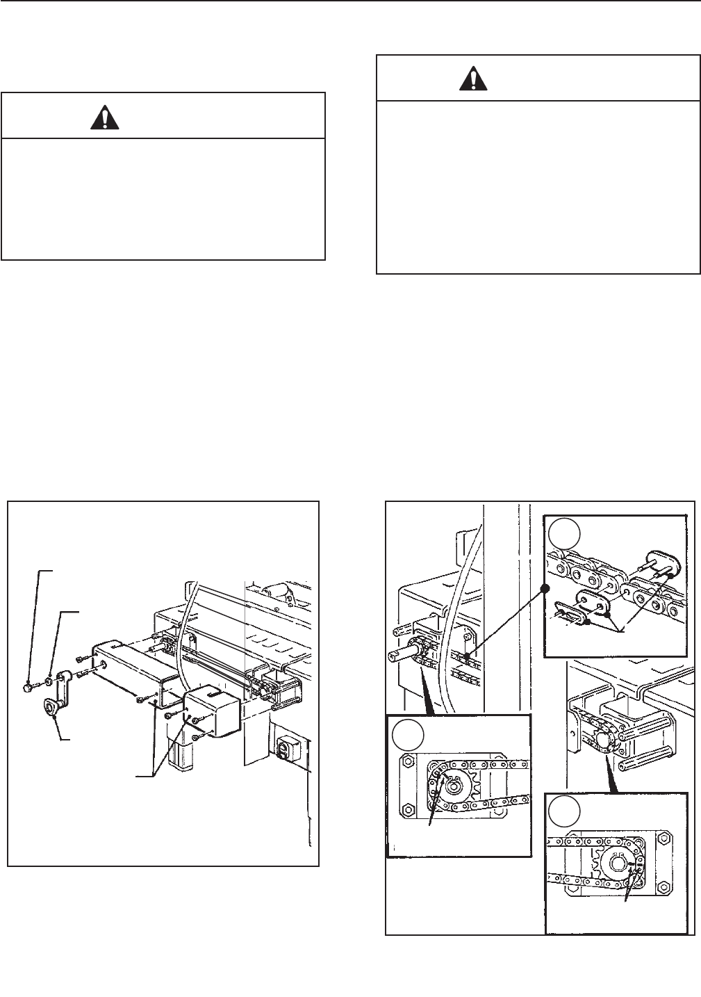
13.11.3 Chain Removal
1. Remove M6 x 16 hex hd screw, special washer
and drive belt width adjustment crank -
Figure 13-10.
2. Remove side covers (2) from each side of ma-
chine bed - Figure 13-10.
3. Remove chain. If necessary, slip width
adjustment crank on shaft and rotate until chain
master link is in convenient position for removal.
Important – Before removing chain, mark both
front and rear sprockets/chain with chalk "
or paint to be sure sprockets/chain when
re-assembled, will be in same position as
before disassembly. Figure 13-11A and
Figure 13-11B. Do not rotate sprockets
once chain is removed. (This would result
in the right and left drive assemblies not
being parallel.)
Remove chain master link and remove chain.
Figure 13-11C.
Figure 13-11 – Chain Removal
Figure 13-10 – Crank/Chain Guards
2010 December
800ab-NA
A
C
B
M6 X 16
Hex Hd Screw
Washer
Crank
Side Covers
Master
Link
Mark Chain
and Sprocket
Mark Chain
and Sprocket
34
THIS PAGE IS BLANK

35
13-MAINTENANCE AND REPAIRS (continued)
13.12 List of the Maintenance Operations
Date: Description of Operation
________ ________________________________________________________________
________ ________________________________________________________________
________ ________________________________________________________________
________ ________________________________________________________________
________ ________________________________________________________________
________ ________________________________________________________________
________ ________________________________________________________________
________ ________________________________________________________________
________ ________________________________________________________________
________ ________________________________________________________________
________ ________________________________________________________________
________ ________________________________________________________________
________ ________________________________________________________________
________ ________________________________________________________________
________ ________________________________________________________________
________ ________________________________________________________________
________ ________________________________________________________________
________ ________________________________________________________________
________ ________________________________________________________________
________ ________________________________________________________________
________ ________________________________________________________________
________ ________________________________________________________________
________ ________________________________________________________________
________ ________________________________________________________________
________ ________________________________________________________________
________ ________________________________________________________________
________ ________________________________________________________________
________ ________________________________________________________________
________ ________________________________________________________________
________ ________________________________________________________________
________ ________________________________________________________________
________ ________________________________________________________________
________ ________________________________________________________________
________ ________________________________________________________________
________ ________________________________________________________________
________ ________________________________________________________________
________ ________________________________________________________________
________ ________________________________________________________________
________ ________________________________________________________________
2010 December
800ab-NA
36
THIS PAGE IS BLANK
37 2010 December
800ab-NA
14-ADDITIONAL INSTRUCTIONS 15-ENCLOSURES / SPECIAL INFO.
14.1 Information for Disposal of Machine (ELV)
The machine is composed of the following materials:
- Steel structure
- Nylon rollers
- Drive belts in PVC
- Nylon pulleys
For machine disposal, follow the regulations
published in each country.
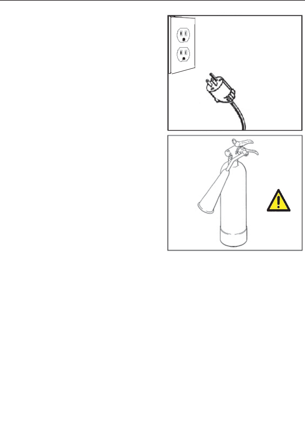
14.2 Emergency Procedures
In case of danger/fi re:
Disconnect plug of power cable from power supply.
(Figure 14-1)
IN CASE OF FIRE
Use a fi re extinguisher that is rated for electrical fi res
(Figure 14-2).
15.1 Statement of Conformity
Not Applicable.
15.2 Emission of Hazardous Substances
Nothing to report
Figure 14-2
Figure 14-1
38
THIS PAGE IS BLANK
39
16-TECHNICAL DIAGRAMS
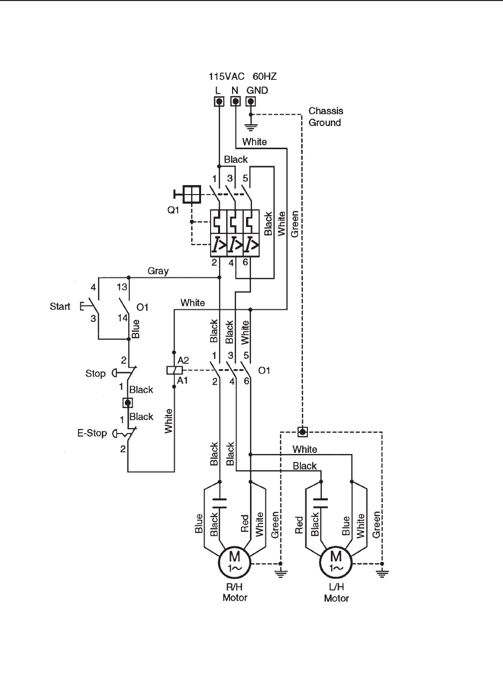
16.1 Electric Diagram
2010 December
800ab-NA

40
16.2 Spare Parts Order
Order parts by quoting the following information:
(Refer to the Identifi cation Plate on the Machine)
• MACHINE MODEL
• SERIAL NUMBER
• FIGURE NO.
• POSITION
• 3M PART NO. (11 DIGITS)
• DESCRIPTION
• QUANTITY
IMPORTANT!
The machine is constantly revised and improved by our designers. The spare parts catalogue is also periodically
updated. It is very important that all the orders of spare parts make reference to the serial number of the machine
(located on the identifi cation plate on the machine).
The manufacturer reserves the right to modify the machine at any time without notice.
It is suggested that the following spare parts be ordered and kept on hand.
800ab
Qty. 3M-Part Number Description
2 78-8076-5452-6 Belt-Drive W/Hook
16-TECHNICAL DOCUMENTATION AND INFORMATION (continued)
2010 December
800ab-NA
Replacement Parts Ordering Information and Service
Refer to the fi rst page of this instruction manual "Replacement Parts and Service Information".
Tool Kit
A tool kit, part number 78-8060-8476-6, is available as a stock item. The kit contains the necessary open end and
hex socket wrenches for use with the metric fasteners on the case sealer. The threading tool, part number
78-8076-4726-4, contained in above kit is also available as a replacement stock item.
Refer to Manual 2 for recommended taping head spare parts.
Label Kit
In the event that any labels are damaged or destroyed, they must be replaced to ensure operator safety. A label
kit, part number 78-8113-6745-3, is available as a stock item. It contains all the safety labels used on the
800ab Adjustable Case Sealer.

41
Part Number Option/Accessory
78-8052-6553-1 Box Hold Down Attachment
78-8069-3983-7 Caster Kit Attachment
70-0066-5081-9 Conveyor Extension Attachment
78-8069-3926-6 Low Tape Sensor Kit
70-0064-4962-6 AccuGlide 3 Lower Taping Head - 2 inch, Type 10800
78-8069-3926-6 Low Tape Sensor Kit
78-8095-4855-1 2 Inch Tape Edge Fold Kit (Lower)
7 Folder Kit
For additional information on the options and accessories listed below, contact your 3M Representative.
Options and Accessories
800ab Adjustable Case Sealer, Type 40800
Frame Assemblies
To Order Parts:
1. Refer to fi rst illustration, Frame Assemblies, for the Figure Number that identifi es a specifi c portion of the
machine.
2. Refer to the appropriate Figure or Figures to determine the parts required and the parts reference number.
3. The Parts List that follows each illustration, includes the Reference Number, Part Number and Part
Description for the parts on that illustration.
Note – The complete description has been included for standard fasteners and some commercially
available components. This has been done to allow obtaining these standard parts locally, if desired.
4. Order parts by Part Number, Part Description and Quantity required. Also include the model/machine name,
machine type, and serial number that are located on the identifi cation plate.
5. Refer to the fi rst page of this instruction manual “Replacement Parts and Service Information” for
replacement parts ordering information.
Important – Not all the parts listed are normally stocked items. Some parts or assemblies shown are
available only on special order. Contact 3M/Tape Dispenser Parts to confi rm item availability.
2010 December
800ab-NA
42
THIS PAGE IS BLANK
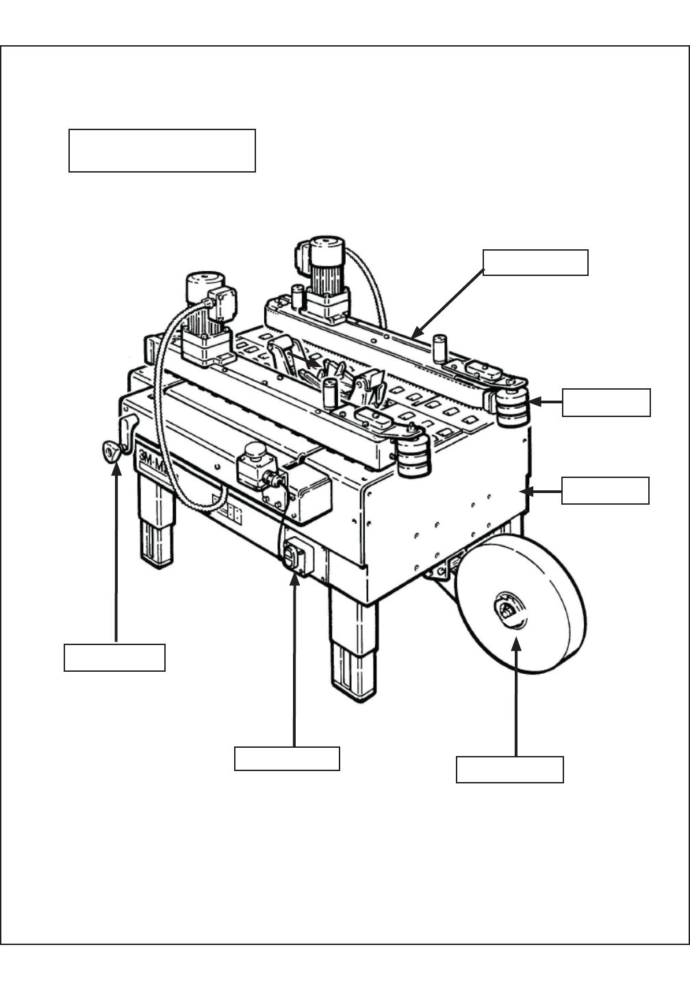
43 2010 December
800ab-NA
Frame
Assemblies
800ab Adjustable Case Sealer
Taping Head Parts
(See Manual 2)
Figure 15231
Figure 15407
Figure 6163
Figure 6174
Figure 6176
Figure 6177
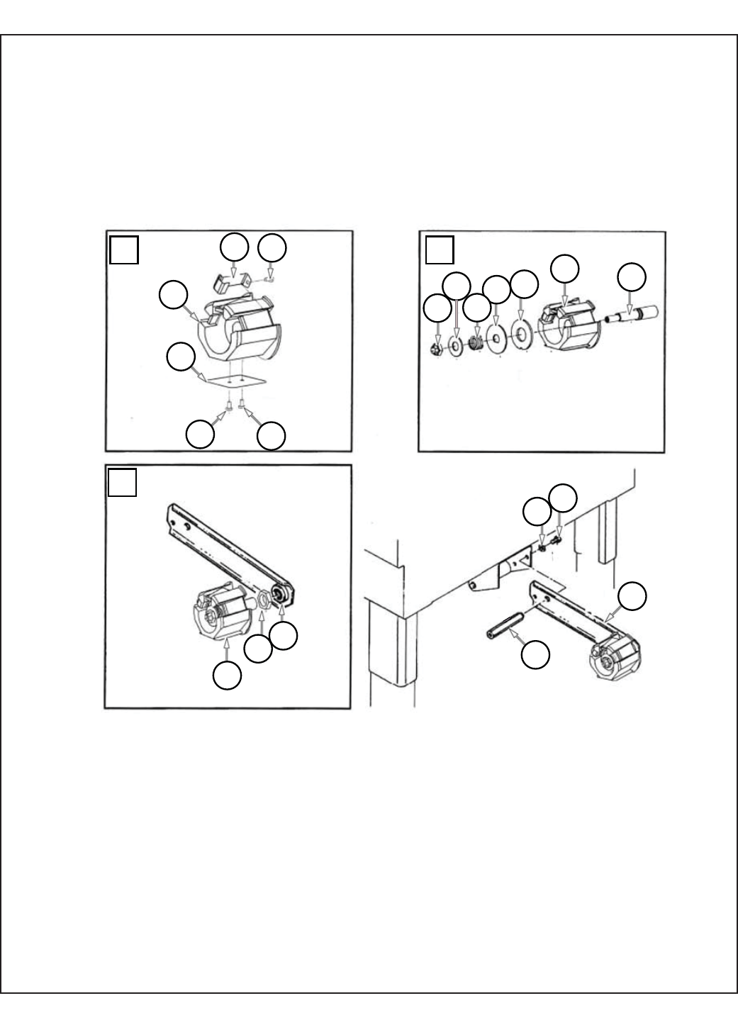
44
4 15
1
15
18 2
7
3
4
7
6
5
7
17
1
12
13 14
8
9
10
11
16
2010 December
800ab-NA
800ab
Figure 15407

45
Figure 10440
Ref. No. 3M Part No. Description
15407-1 78-8070-1565-2 Tape Drum Bracket Assembly
15407-2 78-8070-1395-4 Bracket – Bushing Assembly
15407-3 78-8076-4519-3 Shaft – Tape Drum
15407-4 78-8098-8827-0 Tape Drum Sub-Assembly - 2 Inch
15407-5 78-8098-8749-6 Tape Drum
15407-6 78-8098-8817-1 Leaf Spring
15407-7 26-1002-5753-9 Screw – Self Tapping
15407-8 78-8060-8172-1 Washer – Friction
15407-9 78-8052-6271-0 Washer – Tape Drum
15407-10 78-8100-1048-4 Spring – Core Holder
15407-11 26-1004-5510-9 Washer - Plain, M10
15407-12 78-8070-1215-4 Spacer – Stud
15407-13 26-1000-0010-3 Washer – Flat, M6
15407-14 78-8010-7169-3 Screw – Hex Hd, M6 x 12
15407-15 78-8060-8474-1 Tape Drum Assembly- 2 inch Head
15407-16 78-8017-9077-1 Nut – Self Locking, M10 x 1
15407-17 78-8098-8816-3 Latch - Tape Drum
15407-18 78-8017-9169-5 Nut - M18 x 1
2010 December
800ab-NA
800ab
Figure 2807
Ref. No. 3M Part No. Description
Figure 15407
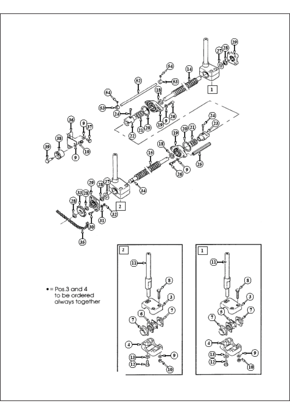
46 2010 December
800ab-NA
800ab
Figure 6163 / 1
Front

47 2010 December
800ab-NA
800ab
Ref. No. 3M Part No. Description
6163-1 78-8100-1229-0 Shaft Assembly – Drive R/H
6163-2 78-8100-1230-8 Shaft Assembly – Drive L/H
6163-3 78-8076-5401-3 Block – Upper
6163-4 78-8076-5402-1 Block – Lower
6163-5 78-8076-5403-9 Nut – Block, R/H
6163-6 78-8076-5404-7 Nut – Block, L/H
6163-7 78-8076-5405-4 Bushing – Block
6163-8 78-8076-5239-7 Screw – Hex Hd, M6 x 50
6163-9 26-1000-0010-3 Washer – Flat M6
6163-10 26-1003-6916-9 Nut – Locking, Plastic Insert M6
6163-11 78-8100-1220-9 Shaft – Drive Mount
6163-12 26-1003-5842-8 Screw – Hex Hd, M8 x 20
6163-13 78-8017-9318-9 Washer – Plain 8 mm
6163-14 78-8076-5407-0 Screw – R/H
6163-15 78-8076-5408-8 Screw – L/H
6163-16 78-8076-5409-6 Screw – Handle, R/H
6163-17 78-8076-5410-4 Screw – Handle, L/H
6163-18 78-8076-5411-2 Spacer – Screw
6163-19 78-8076-5412-0 Flange – W/Bearing
6163-20 78-8060-8010-3 Snap Ring – 42 mm Shaft
6163-21 78-8076-5413-8 Spring
6163-22 78-8076-5414-6 Coupling – Screw, Female
6163-23 78-8076-5415-3 Coupling – Screw, Male
6163-24 26-1003-7946-5 Screw – Soc Hd, M4 x 25
6163-25 78-8076-5416-1 Spacer – Hex, 10 x 107
6163-26 78-8023-2334-1 Screw – Soc Hd, Hex Soc, M6 x 25
6163-27 78-8076-5417-9 Spacer
Figure 6163 / 1
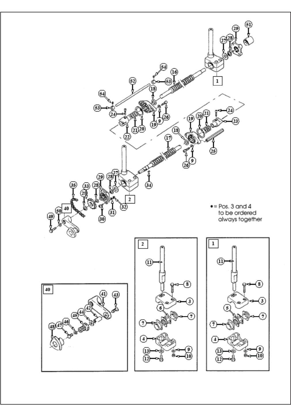
48 2010 December
800ab-NA
800ab
Figure 6166
Figure 6163 / 2
Rear

49 2010 December
800ab-NA
800ab
Ref. No. 3M Part No. Description
6163-28 78-8017-9079-7 Ring – Snap For 15 mm Shaft
6163-29 78-8076-5418-7 Support – Screw
6163-30 26-1003-7949-9 Screw – Soc Hd Hex Soc, M5 x 12
6163-31 78-8005-5741-1 Washer – Plain M5
6163-32 78-8010-7417-6 Nut – Hex M5
6163-33 78-8076-5419-5 Sprocket – 3/8 Inch Z=16
6163-34 78-8046-8135-7 Key – 5 x 5, 12 mm
6163-35 78-8076-5420-3 Chain – 3/8 Inch, 133 Links
6163-36 78-8076-5421-1 Support – Tension Roller
6163-37 78-8010-7169-3 Screw – Hex Hd, M6 x 12
6163-38 78-8070-1503-3 Roller – Chain Tensioning
6163-39 78-8060-7878-4 Idler Screw
6163-40 78-8076-4807-2 Crank Assembly
6163-41 78-8076-5422-9 Crank
6163-42 78-8070-1509-0 Shaft – Crank
6163-43 26-1005-5316-8 Screw – Flat Hd Hex Dr, M5 x 16
6163-44 78-8070-1510-8 Washer – Nylon, 7 x 15 x 1
6163-45 78-8070-1511-6 Bushing
6163-46 78-8005-5740-3 Washer – Plain 4 mm
6163-47 78-8010-7157-8 Screw – Hex Hd, M4 x 10
6163-48 78-8070-1512-4 Knob – VTR-B-M12
6163-49 78-8032-0375-7 Screw – Hex Hd, M6 x 16
6163-50 78-8076-4809-8 Washer – Crank
6163-51 78-8070-1506-6 Cover – Screw
6163-52 78-8076-5423-7 Shaft
6163-53 78-8076-5424-5 Block
6163-54 78-8076-5425-2 Set Screw – M4 x 3
Figure 6163 / 2
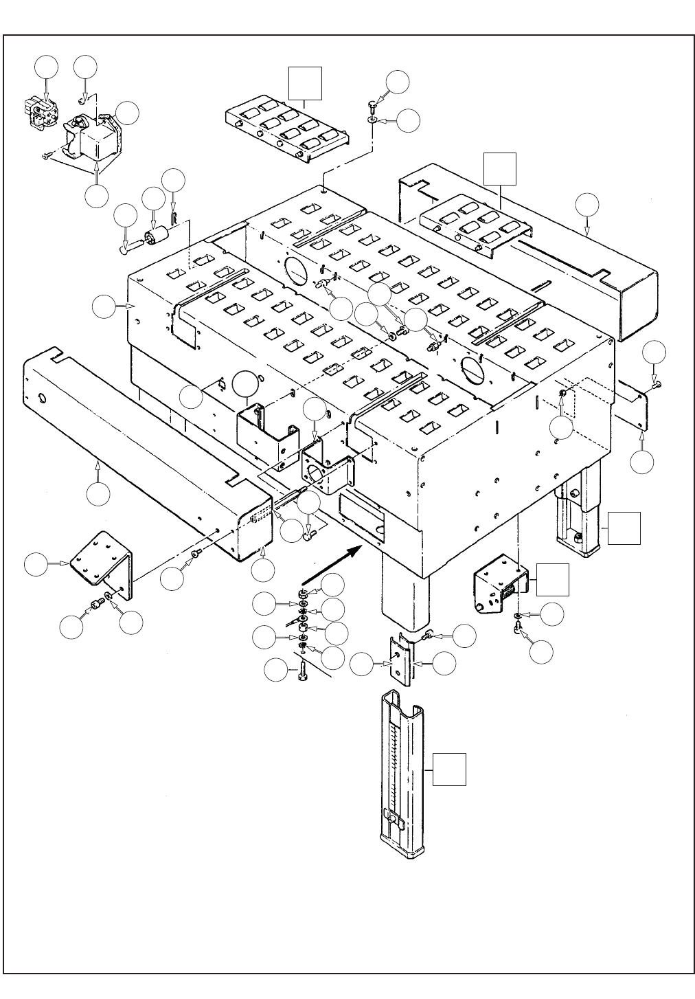
50 2010 December
800ab-NA
800ab
2
22
2
16
24
46
47
47
39
41 40
14
30
32
30
A
A
29
9
7
45 45
36
13 15
1
7
37
32
31
33
38
47
34
28
35
37
29
9
11
12
33
45
43
43
44
44
42
Figure 6174 / 1

51 2010 December
800ab-NA
800ab
Figure 6174 (Page 1 of 2)
Ref. No. 3M Part No. Description
6174-1 78-8076-5380-9 Bed – Conveyor
6174-2 78-8076-5381-7 Leg Assembly – Inner, W/Stop
6174-3 78-8076-5382-5 Leg – Inner
6174-4 78-8060-8480-8 Pad – Foot
6174-5 78-8055-0867-4 Screw – Hex Hd, M8 x 30
6174-6 78-8017-9313-0 Nut –Self-Locking, M8
6174-7 78-8017-9318-9 Washer – Plain 8 mm
6174-8 78-8076-5383-3 Stop – Leg
6174-9 26-1003-7963-0 Screw – Soc Hd, M8 x 16
6174-10 78-8060-8481-6 Label – Height
6174-11 78-8052-6676-0 Clamp – Outer
6174-12 78-8052-6677-8 Clamp – Inner
6174-13 78-8060-7693-7 Roller – 32 x 38
6174-14 78-8076-5384-1 Shaft – Roller
6174-15 78-8076-5385-8 Spring
6174-16 78-8094-6100-3 Conveyor Assembly – Front
6174-17 78-8076-5387-4 Conveyor – Front
6174-18 78-8091-0780-4 Shaft – Central Roller
6174-19 78-8091-0781-2 Shaft – Side Roller
6174-20 26-1003-5828-7 Screw – Hex Hd, M6 x 10 Special
6174-21 78-8076-5389-0 Mounting – Conveyor
6174-22 78-8094-6101-1 Conveyor Assembly – Rear
6174-23 78-8076-5391-6 Conveyor – Rear
6174-24 78-8076-5392-4 Support – Tape Drum
6174-25 78-8060-8483-2 Support – Outboard Roll
6174-26 78-8060-8484-0 Shaft – Roller
Figure 6174 / 1
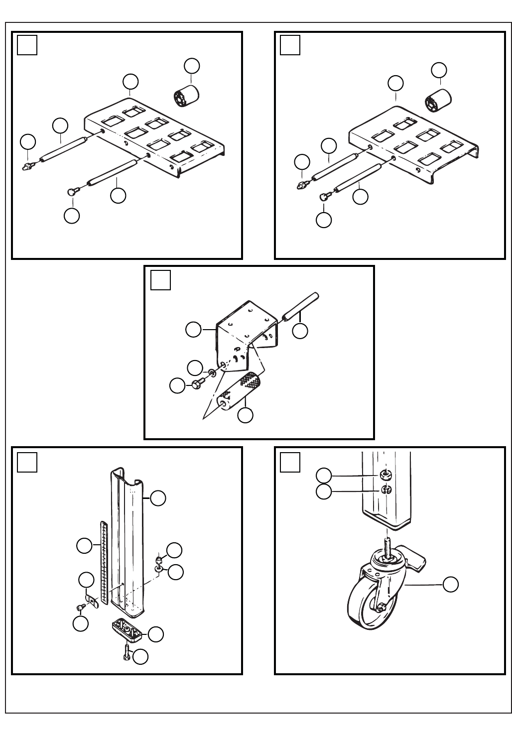
52 2010 December
800ab-NA
800ab
10
13 13
17
19
18
23
7
6
4
9
8
5
3
20
21 19
18
20
21
29
25 26
28
27
51
52
50
2
22
24
49
16
OPTIONAL
Figure 6174/2

53 2010 December
800ab-NA
800ab
Figure 6174 (Page 2 of 2)
Ref. No. 3M Part No. Description
6174-27 78-8060-8485-7 Roller
6174-28 78-8032-0375-7 Screw – Hex Hd M6 x 16
6174-29 26-1000-0010-3 Washer – Flat M6
6174-30 26-1003-7957-2 Screw – Soc Hd Hex Hd M6 x 16
6174-31 78-8060-8487-3 Cover – Switch
6174-32 78-8060-8087-1 Screw – M5 x 10
6174-33 78-8010-7417-6 Nut – Hex M5
6174-34 78-8076-5393-2 Plate – Tape Bracket Support
6174-35 78-8076-5394-0 Spacer
6174-36 78-8076-5483-1 Support – Roller, Chain Tensioning
6174-37 78-8076-5484-9 Cover – R/H
6174-38 78-8113-6836-0 Cover – L/H, W/English Language Label
6174-39 78-8060-7876-8 Cover – Plug, Lateral
6174-40 78-8028-8208-0 Screw – 6P x 9,5
6174-41 78-8060-7873-5 Plug Female
6174-42 78-8060-8488-1 Screw – Hex Hd M5 x 20
6174-43 78-8046-8217-3 Washer – Special
6174-44 78-8005-5741-1 Washer – Plain M5
6174-45 78-8076-4991-4 Spacer
6174-46 26-1003-5841-0 Screw – M8 x 16
6174-47 78-8076-5192-8 Bracket – E-Stop
6174-49 78-8069-3983-7 Caster Assembly
6174-50 26-1009-9096-4 Caster – Dual Locking
6174-51 26-1009-9094-9 Washer – Spring, Helical, M12
6174-52 26-1009-9095-6 Nut – M12
Figure 6174 / 2
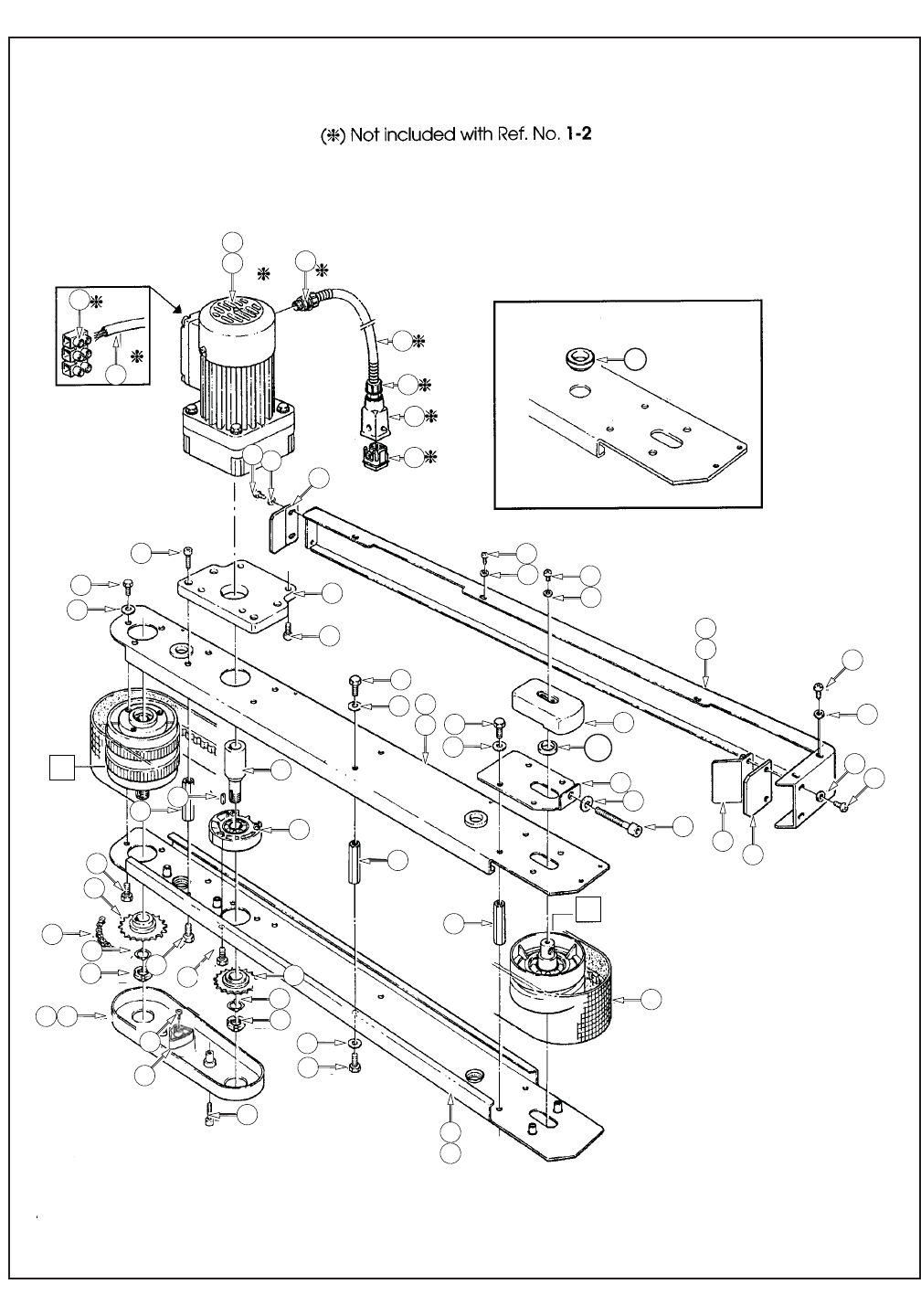
54 2010 December
800ab-NA
800ab
23
35
58
59
60
49
11
15
9
10
20
21
22
55
16
17
48
45 44
45
62
63
57
45
48
13
14
5
6
47
46
12
9
10
48
45
52
56
41
42
39
10
8
43 45
3
4
51
50
10
9
8
19
9
21
34
8
22
54 53
10
9
33
9
18
68
61
67
7
Figure 15230/1
7
40

55 2010 December
800ab-NA
800ab
Figure 15230/1
Ref. No. 3M Part No. Description
15230-1 78-8100-1205-0 Drive Assembly – R/H W/O Motor
15230-2 78-8100-1206-8 Drive Assembly – L/H W/O Motor
15230-3 78-8100-1207-6 Guide – Lower, R/H
15230-4 78-8100-1208-4 Guide – Lower, L/H
15230-5 78-8113-6818-8 Guide – Upper, R/H, W/English Language Label
15230-6 78-8113-6819-6 Guide – Upper, L/H, W/English Language Label
15230-7 78-8091-0500-6 Bushing – Side Drive
15230-8 78-8055-0661-1 Spacer
15230-9 26-1003-5829-5 Screw – Hex Hd, M6 x 12
15230-10 26-1000-0010-3 Washer – Flat M6
15230-11 78-8094-6109-4 Support – Gearmotor
15230-12 78-8023-2334-1 Screw – Soc Hd, Hex Soc, M6 x 25
15230-13 78-8070-1522-3 Gearmotor – Bodine, 42X5BFCI-E2, 15:1, 115V, 60 Hz
78-8100-0865-2 Motor - 220/220v, 50/60 Hz, 3 Phase
78-8052-6718-0 Motor - 220/415v, 50 Hz, 3 Phase
78-8052-6719-8 Motor - 260/440v, 50 Hz, 3 Phase
78-8046-8267-8 Motor - 110/110v, 50/60 Hz, 1 Phase 0.12kw
78-8091-0654-1 Motor - 145v, 60 Hz, 1 Phase
78-8046-8268-6 Motor - 220/240v, 50 Hz, 1 Phase 0.12kw
78-8076-4590-4 Motor - 220/240v, 60 Hz, 1 Phase
15230-14 26-1011-8828-7 Capacitor – 15μF, 300VAC, Motor Run
15230-15 78-8070-1523-1 Screw – 1/4 - 28 x 1/2 SHCS
15230-16 78-8094-6174-8 Extension – Gearmotor
15230-17 78-8076-5439-3 Flange Assembly
15230-18 78-8060-7886-7 Screw – Hex Hd, M6 x 16, Special
15230-19 78-8046-8135-7 Key – 5 x 5, 12 mm
15230-20 78-8137-0934-8 Sprocket – 3/8 Inch, Z-17
15230-21 78-8057-5834-5 Tab Washer
15230-22 78-8057-5835-2 Centering Washer
15230-23 78-8076-5440-1 Pulley Assembly – Drive
15230-24 78-8076-5441-9 Roller – Drive
15230-25 78-8052-6713-1 Ring – Polyurethane
15230-26 78-8055-0669-4 Shaft – Pulley Keyed
15230-27 78-8057-5739-6 Key – M5 x 5 x 30 mm
15230-28 78-8055-0668-6 Washer – 15/26 x 1
15230-29 78-8091-0382-9 Belleville Washer – /16
15230-30 78-8076-5442-7 Flange Assembly
15230-31 26-0001-5862-1 Screw – Flat Hd Soc, M5 x 12
15230-32 78-8054-8877-8 Washer – 5,5/20 x 4
15230-33 78-8137-0935-5 Sprocket 3/8'' Z20
15230-34 78-8076-4933-6 Chain – 3/8 Inch Pitch, 52 Pitch
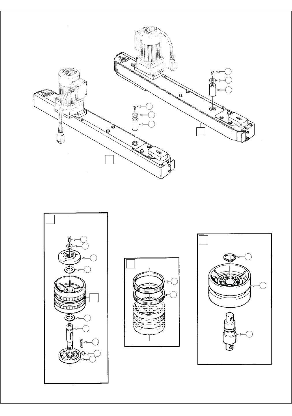
56 2010 December
800ab-NA
800ab
1
2
24
23
35
24
25
66
65
64
66
65
64
31
32
30
29
38
36
28
26
27
19
30
37
25
Figure 15230/2

57 2010 December
800ab-NA
800ab
Figure 15230/2
Ref. No. 3M Part No. Description
15230-35 78-8076-5443-5 Pulley Assembly – Idler
15230-36 78-8055-0660-3 Roller – Idler
15230-37 78-8076-5444-3 Shaft – Idler Pulley
15230-38 12-7997-0272-0 E-Ring – M-25
15230-39 78-8076-5445-0 Tensioning – Belt
15230-40 78-8076-5446-8 Washer – Shaft
15230-41 78-8070-1519-9 Screw – Soc Hd, Hex Hd, M8 x 70
15230-42 78-8017-9318-9 Washer – Plain 8 mm
15230-43 78-8076-5448-4 Cover – Belt Tensioner
15230-44 78-8055-0850-0 Screw – Cap, M4 x 6
15230-45 78-8005-5740-3 Washer – Plain 4 mm
15230-46 78-8100-1211-8 Cover – Drive, R/H
15230-47 78-8100-1212-6 Cover – Drive, L/H
15230-48 26-1002-5753-9 Screw – Self-Tapping
15230-49 78-8100-1213-4 Guard – Belt
15230-50 78-8100-1214-2 Guard – Rubber
15230-51 78-8100-1215-9 Guard – Metal
15230-52 78-8076-5255-3 Screw – Phillips Hd, M4 x 12
15230-53 78-8091-0764-8 Cover – Chain, Right
15230-54 78-8091-0765-5 Cover – Chain, Left
15230-55 78-8010-7165-1 Screw – Flat Hd Soc, M5 x 25
15230-56 78-8076-5452-6 Belt – Box Drive
15230-57 78-8060-7631-7 Connector – 3/8 Inch
15230-58 78-8076-5197-7 Sleeving – /12, 800 mm
15230-59 78-8060-7626-7 Connector – PG 11/12
15230-60 78-8060-7877-6 Plug Housing – Vertical
15230-61 78-8060-7875-0 Plug Male
15230-62 78-8060-8053-3 Wire – 3-Pole, 5 Meters Length
15230-63 78-8076-4968-2 Terminal
15230-64 78-8076-5453-4 Roller
15230-65 78-8054-8577-4 Washer – Special
15230-66 26-1001-9843-6 Screw – Flat Soc Hd, M6 x 16
15230-67 78-8010-7210-5 Screw - Tensioner
15230-68 78-8137-0932-2 Tensioner - Pulley R/H
78-8137-0933-2 Tensioner - Pulley L/H
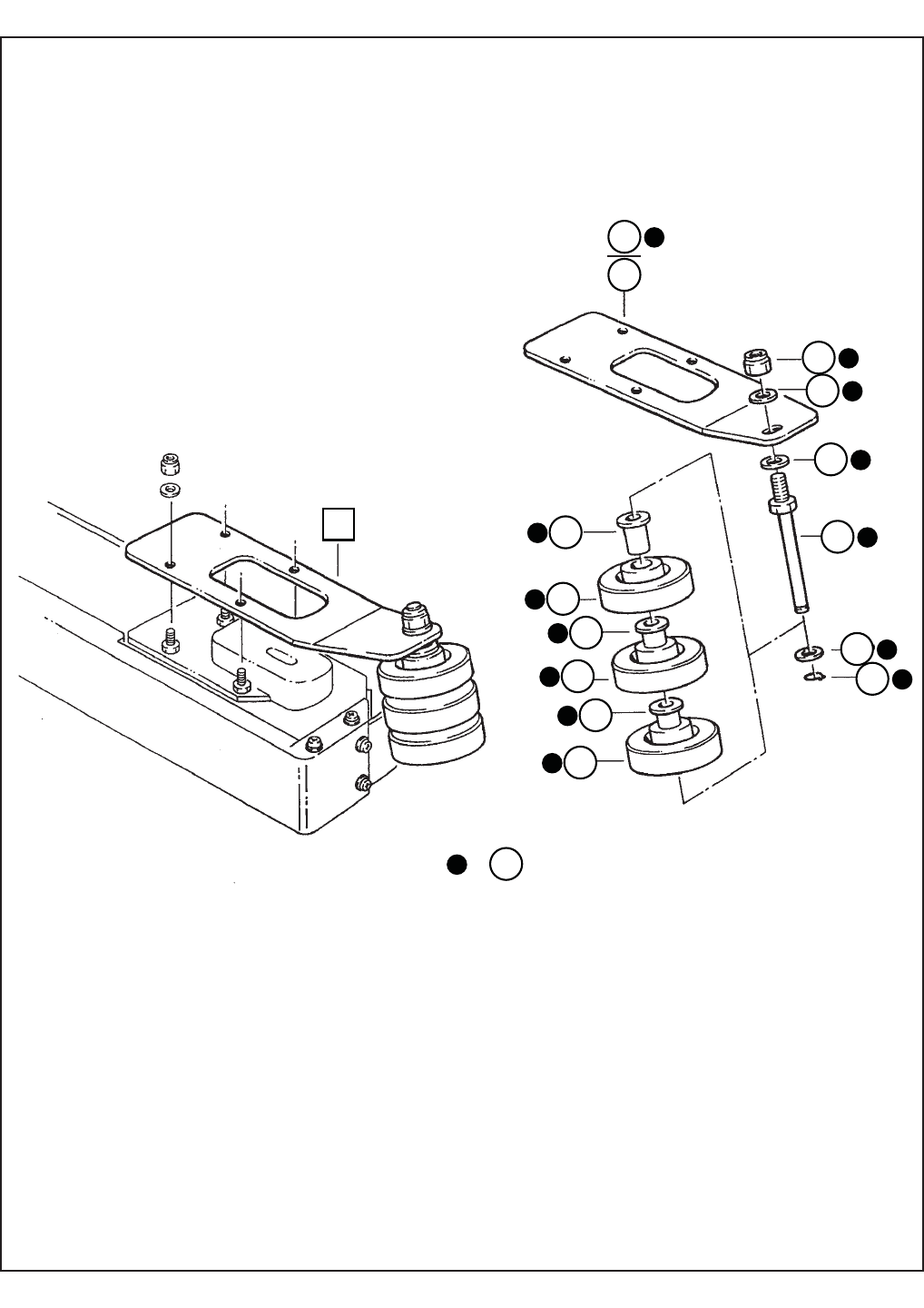
58
800ab
2010 December
800ab-NA
10
2
8
8
89
5
6
6
6
7
7
7
3
4
1
=
Figure 6176

59
Figure 6176
Ref. No. 3M Part No. Description
6176-1 78-8100-1225-8 Slide Compression Roller – R/H
6176-2 78-8100-1226-6 Slide Compression Roller – L/H
6176-3 78-8113-6984-8 Bracket – Roller, R/H, W/English Language Label
6176-4 78-8113-6985-5 Bracket – Roller, L/H, W/English Language Label
6176-5 78-8076-5491-4 Shaft – Roller
6176-6 78-8060-8106-9 Bushing – Nylon
6176-7 78-8055-0821-1 Rubber Roller
6176-8 78-8052-6566-3 Washer – Friction
6176-9 78-8016-5855-6 E-Ring – 10 mm
6176-10 26-1003-6918-5 Nut – Hex Flange M10, Plastic Insert
2010 December
800ab-NA
800ab
Figure 6176
6176-8 26-1004-5510-9 Washer - Plain M10
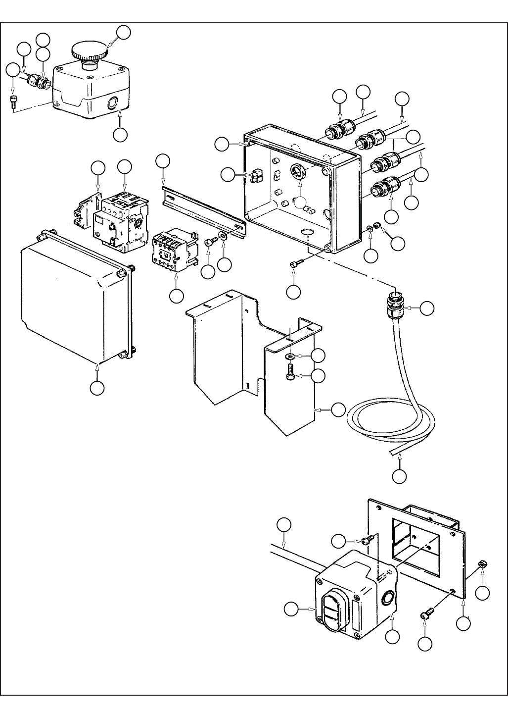
60 2010 December
800ab-NA
800ab
7
3
3
2
2
9
6
6
6
5
4
21
18
18
18
18
15
11
10
12
16
17
19
20
24
1
8
22
21 23
26
25
13
14
17
27
6
7
Figure 6177

61 2010 December
800ab-NA
800ab
Figure 6177
Ref. No. 3M Part No. Description
6177-1 78-8094-6379-3 Support Box
6177-2 78-8113-6759-4 Box – W/English Language Label
6177-3 78-8094-6381-9 Screw – Soc Hd, Hex Hd, M4 x 15
6177-4 78-8005-5740-3 Washer – Plain, 4 mm
6177-5 26-1003-6914-4 Nut – Plastic Insert, M4
6177-6 78-8076-4715-7 Cord Grip
6177-7 78-8076-5211-6 Set Nut – GMP13.5
6177-8 78-8057-5807-1 Cord Grip – ST 16
6177-9 78-8094-6382-7 Guide – Mounting
6177-10 78-8028-8208-0 Screw – 6PX9,5
6177-11 78-8017-9018-5 Washer – Plain, M4 SPEC
6177-12 78-8094-6383-5 Contactor - Allen Bradley 110V, 60Hz
78-8100-0830-6 Contactor - Allen Bradley 220V, 50HZ
78-8100-0831-4 Contactor - Allen Bradley 380V, 50HZ
6177-13 78-8076-5378-3 Circuit Breaker - Allen Bradley 1.6-2.5A
78-8100-0755-5 Circuit Breaker - Allen Bradley 2.5-4 A
78-8114-4600-0 Circuit Breaker - Allen Bradley 6.3-10a
78-8076-5223-1 Circuit Breaker - Allen Bradley 1-1.6A
78-8119-8965-2 Circuit Breaker - Allen Bradley
6177-14 78-8094-6384-3 Clamp – VGPE 4/6
6177-15 78-8076-4968-2 Terminal
6177-16 26-1009-8724-2 Power Cord W/Plug – Type SO
6177-17 78-8100-1038-5 Cable – 3X20 AWG, 5 MT
6177-18 78-8060-8053-3 Wire – 3-Pole, 5 Meters Length
6177-19 26-1003-7957-2 Screw – Soc Hd, Hex Hd, M6 x 16
6177-20 26-1000-0010-3 Washer – Flat, M6
6177-21 78-8119-6528-0 E-Stop Enclosure – W/English Language Label
6177-22 78-8094-6386-8 Switch – On/Off, Sprecher & Schuh, DM3N-C-01/10
6177-23 78-8113-6887-3 Support – On/Off Switch, W/English Language Label
6177-24 78-8017-9257-9 Screw – M4 x 10
6177-25 78-8060-8087-1 Screw – M5 x 10
6177-26 78-8010-7417-6 Nut – Hex, M5
6177-27 78-8094-6385-0 E-Stop - Allen Bradley, 800EP-MTS643LX01
Figure 6177
62
THIS PAGE IS BLANK

TM
AccuGlide™ is a Trademark of
3M, St. Paul, MN 55144-1000
Printed in U.S.A.
© 3M 2009 44-0009-2070-0 (A120709-NA)
AccuGlide 3
Upper and Lower
Taping Heads -
2 Inch
Type 10800
Instructions and
Parts List
Serial No._____________________________________
For reference, record taping head(s) serial number(s) here.
Important Safety
Information
BEFORE INSTALLING
OR OPERATING THIS
EQUIPMENT
Read, understand, and
follow all safety and
operating instructions.
It is recommended you
immediately order the
spare parts listed in the
"Spare Parts/Service
Information" section. These
parts are expected to wear
through normal use, and
should be kept on hand
to minimize production
delays.
Spare Parts
3M Industrial Adhesives and Tapes
3M Center, Building 220-5E-06
St. Paul, MN 55144-1000
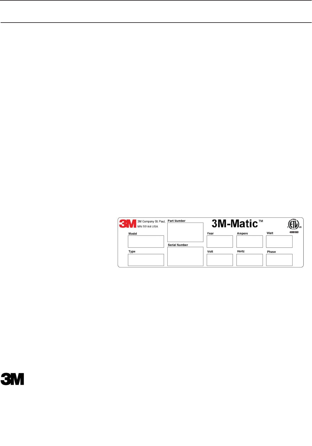
3M-Matic™, AccuGlide™ and Scotch™ are Trademarks of
3M St. Paul, MN 55144-1000
Printed in U.S.A.
© 3M 2009 44-0009-1851-4 (H031008)
3M Industrial Adhesives and Tapes
3M Center, Building 220-5E-06
St. Paul, MN 55144-1000
To Our Customers:
This is the 3M-Matic™/AccuGlide™/Scotch® equipment you ordered. It has been set up and tested in
the factory with Scotch® tapes. If technical assistance or replacement parts are needed, call or fax the
appropriate number listed below.
Included with each machine is an Instructions and Parts List manual.
Technical Assistance / Replacement Parts and Additional Manuals:
Call the 3M-Matic™ Help line at 1-800 328-1390. Provide the customer support coordinator with the model/
machine name, machine type, and serial number that are located on the identif cation plate (For example:
Model 700a - Type 39600 - Serial Number 13282).
Minimum billing on parts orders will be $25.00. Replacement part prices available on request.
$10.00 restocking charge per invoice on returned parts
Note : Outside the U.S., contact the local 3M subsidiary for
parts ordering information.
United States -
3M Tape Dispenser Parts
241 Venture Drive
1-800-344-9883
Amery, WI 54001-1325
Fax: 1-715-268-8153
Identif cation Plate
Replacement Parts and Service Information
i
THIS PAGE IS BLANK

Replacement Parts And Service Information
To Our Customers:
This is the 3M-Matic™/AccuGlide™/Scotch® equipment you ordered. It has been set up
and tested in the factory with Scotch® tapes. If any problems occur when operating this equipment and
you desire a service call or phone consultation, call, write, or fax the appropriate number listed below.
Included with each machine is an Instructions and Parts List manual.
SERVICE, REPLACEMENT PARTS, AND ADDITIONAL MANUALS
AVAILABLE DIRECT FROM:
Order parts by part number, part description, and quantity required. Also, when ordering parts
or additional manuals, include model/machine name, machine type, and serial number that are
located on the identifi cation plate.
3M-Matic™, AccuGlide™ and Scotch™ are Trade-
marks of 3M, St. Paul, MN 55144-1000
Printed in U.S.A.
© 3M 2009 44-0009-1852-2 (F031008)
3M Industrial Adhesives and Tapes
3M Center, Building 220-5E-06
St. Paul, MN 55144-1000
ii
THIS PAGE IS BLANK

7
Instruction Manual
AccuGlide™ 3
Upper and Lower Taping Heads - 2 Inch
Type 10800
Table of Contents Page
Replacement Parts and Service Information ............................................................................................ i - ii
Table of Contents...................................................................................................................................... iii
Equipment Warranty and Limited Remedy ............................................................................................... iv
Intended Use ............................................................................................................................................ 1
Taping Head Contents / How to Use Manual............................................................................................ 3
Important Safeguards ............................................................................................................................... 4 - 5
Specifi cations ........................................................................................................................................... 6 - 7
Dimensional Drawing .................................................................................................................... 7
Installation ................................................................................................................................................ 8
Receiving and Handling ................................................................................................................ 8
Installation Guidelines ................................................................................................................... 8
Tape Leg Length ........................................................................................................................... 8
Tape Width Adjustment ................................................................................................................. 8
Operation .................................................................................................................................................. 9 - 11
Tape Loading – Upper Taping Head .............................................................................................. 10
Tape Loading – Lower Taping Head .............................................................................................. 10 - 11
Maintenance ............................................................................................................................................. 12 - 13
Blade Replacement ....................................................................................................................... 12
Blade Guard .................................................................................................................................. 12
Blade Oiler Pad ............................................................................................................................. 12
Cleaning ........................................................................................................................................ 13
Applying/Buffi ng Roller Replacement ............................................................................................ 13
Adjustments .............................................................................................................................................. 14 - 16
Tape Latch Alignment .................................................................................................................... 14
Tape Drum Friction Brake ............................................................................................................. 14
Applying Mechanism Spring .......................................................................................................... 15
One-Way Tension Roller ............................................................................................................... 15
Tape Leg Length ........................................................................................................................... 16
Leading Tape Leg Length Adjustment ............................................................................ 16
Changing Tape Leg Length From 70 to 50 mm [2-3/4 to 2 Inch] .................................... 16
Troubleshooting Guide ............................................................................................................................. 17 - 18
Spare Parts/Service Information............................................................................................................... 19
Recommended Spare Parts .......................................................................................................... 19
Replacement Parts and Service .................................................................................................... 19
Replacement Parts Illustrations and Parts List ................................................................ ...................... 21 - End of Manual
iii

8
AccuGlide™, Scotch™, and 3M-Matic™ are Trademarks of 3M, St. Paul, Minnesota 55144-1000
Equipment Warranty and Limited Remedy: THE FOLLOWING WARRANTY IS MADE IN LIEU OF ALL OTHER
WARRANTIES, EXPRESS OR IMPLIED, INCLUDING, BUT NOT LIMITED T O, ANY IMPLIED WARRANTY OF
MERCHANTABILITY OR FITNESS FOR A PARTICULAR PURPOSE AND ANY IMPLIED WARRANTY ARISING
OUT OF A COURSE OF DEALING, CUSTOM OR USAGE OF TRADE:
Limitation of Liability: Except where prohibited by law, 3M and seller will not be liable for any loss or damage
arising from this 3M equipment, whether direct, indirect, special, incidental, or consequential, regardless of the legal
theory asserted, including breach of warranty, breach of contract, negligence, or strict liability.
Note: The foregoing Equipment Warranty and Limited Remedy and Limitation of Liability may be changed only by
a written agreement signed by authorized representatives of 3M and seller.
3M sells its AccuGlide™ 3 Upper and Lower Taping Heads - 2 Inch, Type 10800 with the
following warranty:
1. The Taping Head blade, springs and rollers will be free from defects in material and manufacture for
ninety (90) days after delivery.
2. All other Taping Head parts will be free from defects in material and manufacture for three (3) years after
delivery.
If any part is defective within this warranty period, your exclusive remedy and 3M’s and seller’s sole obligation
shall be, at 3M’s option, to repair or replace the part. 3M must receive actual notice of any alleged defect within
a reasonable time after it is discovered, but in no event shall 3M have any obligation under this warranty unless it
receives such notice within fi ve (5) business days after the expiration of the warranty period. All notices required
hereunder shall be given to 3M solely through the 3M-Matic™ Help line (800-328-1390). To be entitled to repair
or replacement as provided under this warranty, the part must be returned as directed by 3M to its factory or other
authorized service station designated by 3M. If 3M is unable to repair or replace the part within a reasonable time
after receipt thereof, 3M, at its option, will replace the equipment or refund the purchase price. 3M shall have no
obligation to provide or pay for the labor required to remove any part or equipment or to install the repaired or
replacement part or equipment. 3M shall have no obligation to repair or replace those parts failing due to normal
wear, inadequate or improper maintenance, inadequate cleaning, non-lubrication, improper operating environ-
ment, improper utilities, operator error or misuse, alteration or modifi cation, mishandling, lack of reasonable care,
or due to any accidental cause.
iv
AccuGlide 3 Taping Head - 2" 2009 February
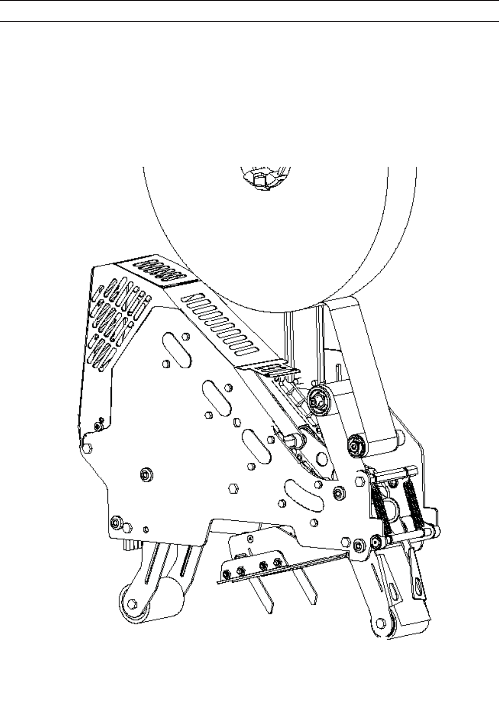
1
Intended Use
The intended use of the AccuGlide™ 3 Upper and
Lower Taping Heads - 2 Inch is to apply a "C" clip of
Scotch® pressure-sensitive fi lm box sealing tape to
the top and/or bottom center seam of regular slotted
containers.
These taping heads are incorporated into most
standard 3M-Matic™ case sealers. The compact
size and simplicity of the taping head also makes
it suitable for mounting in box conveying systems
other than 3M-Matic™ case sealers. This includes
replacement of other types of taping, gluing or
stapling heads in existing case sealing machines.
The AccuGlide™ 3 Upper and Lower Taping Heads
- 2 Inch have been designed and tested for use with
Scotch® pressure-sensitive fi lm box sealing tape.
AccuGlide™ 3 Upper Taping Head - 2 inch, Type 10800
AccuGlide 3 Taping Head - 2" 2009 February
2
THIS PAGE IS BLANK

3
AccuGlide™ 3
Upper and Lower Taping Heads - 2 Inch
- consists of:
Qty. Part Name
1 Taping Head Assembly
1 Tape Drum and Bracket Assembly
1 Hardware and Spare Parts Kit
1 Threading Tool
General Information
How to use this Manual
This instruction manual covers safety aspects, handling and transport, storage, unpacking, preparation, installa-
tion, operation, set-up and adjustments, technical and manufacturing specifi cations, maintenance, troubleshoot-
ing, repair work and servicing, electric diagrams, warranty information, disposal (ELV), a glossary with a defi nition
of symbols, plus a parts list 3M Industrial Adhesives and Tapes Division 3M Center, Bldg. 220-5E-06 St. Paul, MN
55144-1000 (USA) Edition February 2009/Copyright 3M 2009. All rights reserved The manufacturer reserves the
right to change the product at any time without notice Publication
© 3M 2009.
The manual is an important part of the machine; all information contained herein is intended to enable the equip-
ment to be maintained in perfect condition and operated safely. Ensure that the manual is available to all opera-
tors of this equipment and the manual is kept up to date with all subsequent amendments. Should the equipment
be sold or disposed of, please ensure that the manual is passed on with the machine.
Electrical and pneumatic diagrams are included in the manual. Equipment using PLC controls and/or electronic
components will include relevant schematics or programs in the enclosure (or will be delivered separately as
needed)
Keep the manual in a clean and dry place near the machine. Do not remove, tear or rewrite parts of the manual
for any reason. Use the manual without damaging it. However, if the manual has been lost or damaged, ask your
after sale service for a new copy (if it is possible, please have the manual name, part number, and revision infor-
mation and/or model/machine name, machine type, and serial number) that are located on the identifi cation plate
(For example: Model 700a - Type 39600 - Serial Number 13282).
NOTE:
All the important warning notes related to the operation of the machine are identifi ed by the symbol:
Updating the Manual
Modifi cations to the machine are subject to manufacturer's internal procedures. The user may receive pages or
parts of the manual which contain amendment made after its fi rst publication. The user must use them to update
this manual.
Taping Head Contents
AccuGlide 3 Taping Head - 2" 2009 February
4
Important Safeguards
This safety alert symbol identif es
important safety messages in this
manual. READ AND UNDERSTAND
THEM BEFORE INSTALLING OR
OPERATING THIS EQUIPMENT.
• To reduce the risk associated with
mechanical hazards:
− Read, understand and follow all safety
and operating instructions before
operating or servicing the case sealer
− Allow only properly trained and qualifi ed
personnel to operate and/or service this
equipment
• To reduce the risk associated with
shear, pinch, and entanglement
hazards:
− Turn air and electrical supplies off on
associated equipment before perform-
ing any adjustments, maintenance, or
servicing the taping heads
− Never attempt to work on the taping
head or load tape while the box drive
system is running
• To reduce the risk associated with sharp
blade hazards:
− Keep hands and fi ngers away from tape
cutoff blades under orange blade
guards. The blades are extremely sharp
Explanation of Signal Word Consequences
Indicates a potentially hazardous
situation, which, if not avoided,
may result in minor or moderate
injury and/or property damage.
CAUTION
Indicates a potentially hazardous
situation, which, if not avoided,
could result in death or serious
injury and/or property damage.
WARNING:
WARNING
• To reduce the risk associated with muscle
strain:
− Use proper body mechanics when
removing or installing taping heads that are
moderately heavy or may be considered
awkward to lift
• To reduce the risk associated with impact
hazards:
− Place the taping head on a smooth level
surface when maintaining or servicing this
equipment
CAUTION
(Important Safeguards continued on next page)
AccuGlide 3 Taping Head - 2" 2009 February
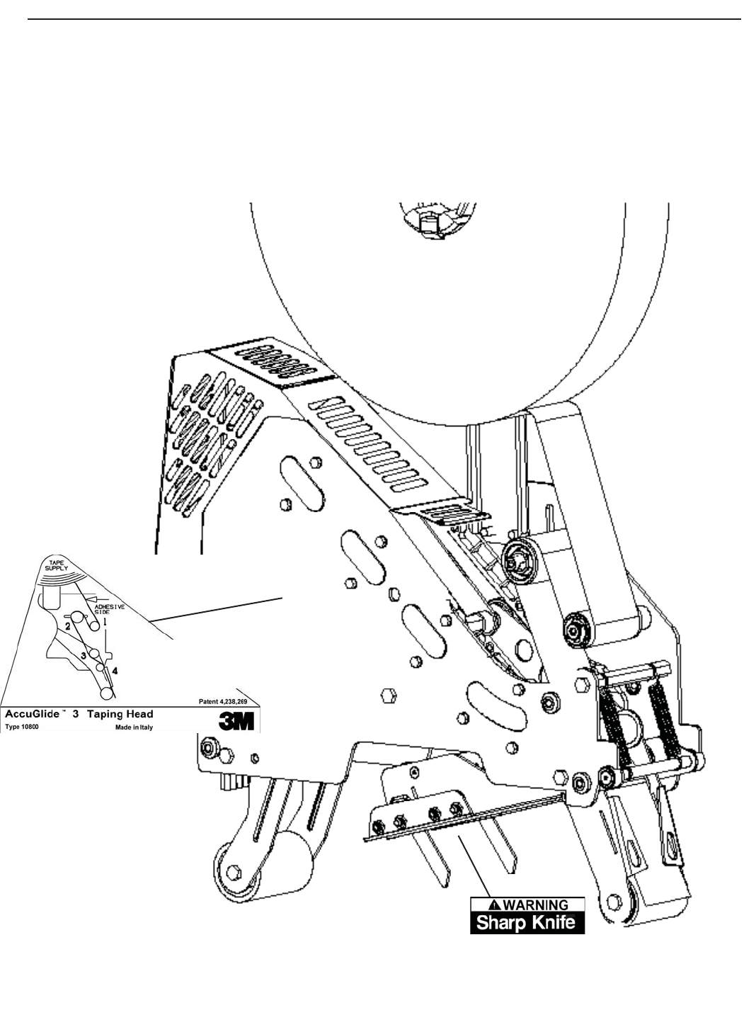
5
Important Safeguards (Continued)
78-8070-1335-0
Figure 1-1 Replacement Labels/3M Part Numbers
AccuGlide 3 Taping Head - 2" 2009 February
Important - In the event the following safety labels are damaged or destroyed, they must be replaced to
ensure operator safety. See "Replacement Parts Illustrations and Parts Lists" for label part numbers.
Upper Taping Head Label 78-8137-3317-3
Lower Taping Head Label 78-8137-3316-5

6
Specif cations
1. Tape:
For use with Scotch® pressure-sensitive fi lm box sealing tapes.
2. Tape Width:
36mm or 1-1/2 inches minimum to 48mm [2 inches] maximum.
3. Tape Roll Diameter:
Up to 405mm [16 inches] maximum on a 76.2mm [3 inch] diameter core.
(Accommodates all system roll lengths of Scotch® fi lm tapes.)
4. Tape Application Leg Length - Standard:
70mm ± 6mm [2-3/4 inches ±1/4 inch]
Tape Application Leg Length - Optional:
50mm ± 6mm [2 inches ± 1/4 inch] (See "Adjustments – Tape Leg Length.")
5. Box Size Capacities:
For use with center seam regular slotted containers.
Length – 443mm [17.44 inches] w/ Guard
Height – 406mm [16 inches] w/ Guard
Width – 107mm [4.2 inches]
When upper and lower taping heads are used on “3M-Matic” case sealers, refer to the respective instruction
manual specifi cations for box weight and size capacities.
6. Operating Rate:
Conveyor speeds up to 0.5 m/s [100 feet per minute].
7. Operating Conditions:
Use in dry, relatively clean environments at 5° to 40°C [40° to 105°F] with clean dry boxes.
Important – Taping heads should not be washed down or subjected to conditions causing moisture
condensation on components.
8. Taping Head Dimensions:
Length – 442mm [17 3/8 inches]
Height – 648mm [25 1/2 inches] (with tape drum)
Width – 105mm [4-1/8 inches] (without mounting spacers)
Weight – Packaged: 8.6kg [19 lbs.] Unpackaged: 7.7kg [17 lbs.]
(Specifi cations continued on next page.)
AccuGlide 3 Taping Head - 2" 2009 February
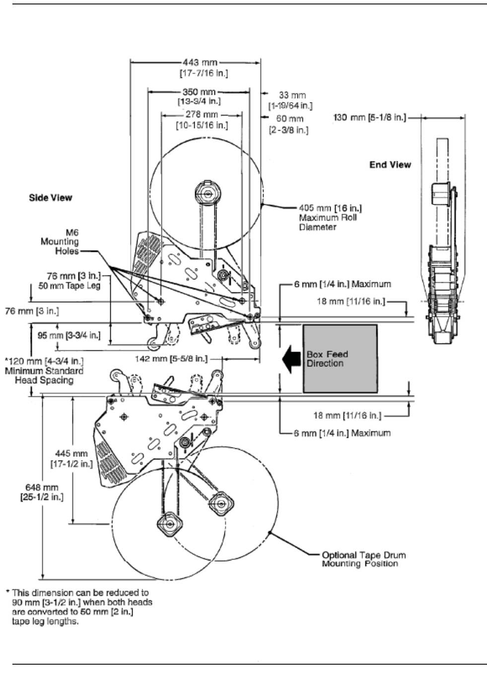
7
AccuGlide 3 Taping Head - 2" 2009 February
Figure 2/1 Dimensional Drawing
Specif cations
8
Installation
1. The box conveying system must positively
propel the box in a continuous motion, not
exceeding 30.5 m/min [100 feet per minute],
past the taping head assembly since the box
motion actuates the taping mechanism.
2. If a pusher or cleated conveyor is being used,
steps should be taken in the conveyor design to
prevent the pusher from contacting the applying
or buffi ng roller arms resulting in damage to the
taping head.
Receiving And Handling
After the taping head assembly has been
unpackaged, examine the unit for damage that
might have occurred during transit. If damage is
evident, fi le a damage claim immediately with the
transportation company and also notify your 3M
Representative.
Installation Guidelines
The taping head assembly can be used in convert-
ing existing or in custom made machinery.
It can be mounted for top taping or bottom taping.
Refer to "Box Size Capacities," as well as Figure
2-1 in the Specifi cations section, for the following
points in making such installations:
4. Mounting studs are provided with the taping
head, but special installations may require
alternate means for mounting.
5. Box hold-down or guides should be provided
and the taping head mounted so that the side
plates are 6mm [1/4 inch] maximum away from
the surface on which the box rides.
Tape Leg Length
Taping heads are factory set to apply standard
70mm [2-3/4 inch] tape legs. The heads can be con-
verted to apply 50 mm [2 inch] tape legs if desired
but both upper and lower heads should be set to
apply the same tape leg length. See "Adjustments –
Changing Tape Leg Length From 70 to 50mm
[2-3/4 to 2 Inches]."
Also, the conveyor speed at which the product
moves through the taping heads, affects the leading
and trailing tape leg length. See "Adjustments sec-
tion – Leading Tape Leg Length Adjustment."
Tape Width Adjustment
Taping heads are factory set to apply 48mm [2 inch]
wide tape. If it is necessary to align the tape or to
apply narrower tapes, refer to "Adjustments – Tape
Web Alignment" for set-up procedure.
Note – AccuGlide™ 3 Upper and Lower Taping
Heads - 2 Inch is supplied with a buffi ng
arm guard. Adjustments may be required to
install the taping head into some older design
3M-Matic™ case sealers.
3. Figure 2-1 illustrates the typical mounting
relationship for opposing taping head
assemblies to allow taping of box heights down
to 90mm [3-1/2 inches].
• To reduce the risk associated with sharp blade hazards:
- Keep hands and fi ngers away from tape cutoff blades under orange blade guards.
The blades are extremely sharp
WARNING
Important – Always conduct a hazard review to
determine appropriate guarding requirements
when the installation is in an application other
than 3M-Matic (TM) equipment
• To reduce risk associated with muscle strain:
- Use proper body mechanics when
removing or installing taping heads
that are moderately heavy or may be
considered awkward to lift
CAUTION
AccuGlide 3 Taping Head - 2" 2009 February
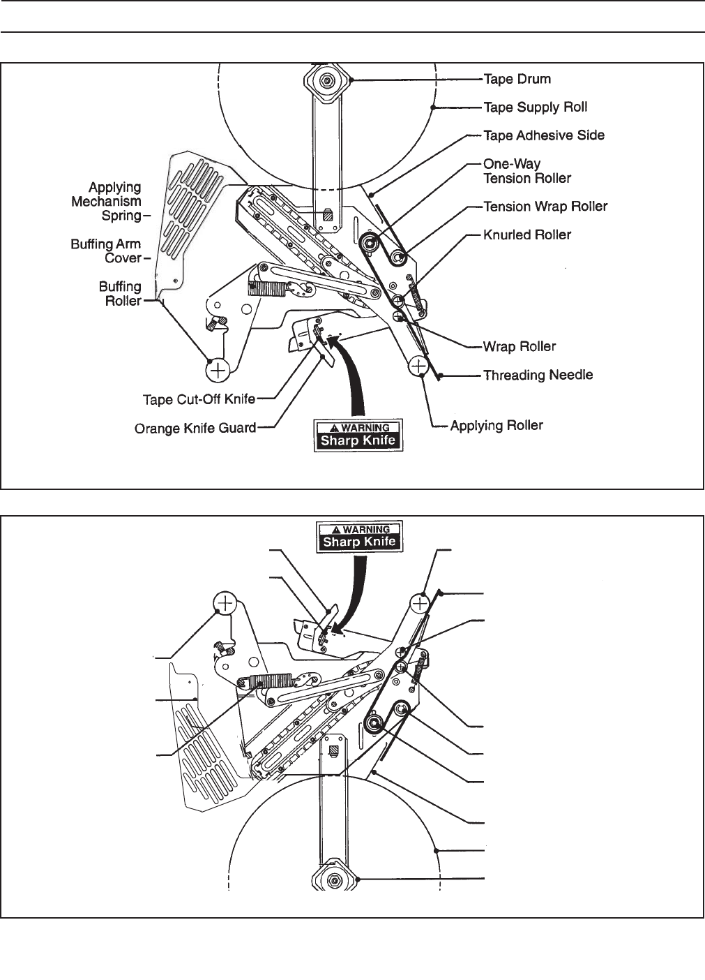
9
Operation
(Operation continued on next page.)
Figure 3-1 Taping Head Components/Threading Diagram - Upper Head (Left Side) View)
Figure 3-2 Taping Head Components/Threading Diagram - Lower Head (Left Side) View)
Tape Drum
Tape Supply Roll
Tape Adhesive Side
Tension Wrap Roller
Knurled Roller
Wrap Roller
Threading Needle
Applying Roller
One-Way
Tension Roller
Applying
Mechanism
Spring
Buff ng Arm
Cover
Buff ng
Roller
Orange Knife Guard
Tape Cut-Off Knife
AccuGlide 3 Taping Head - 2" 2009 February
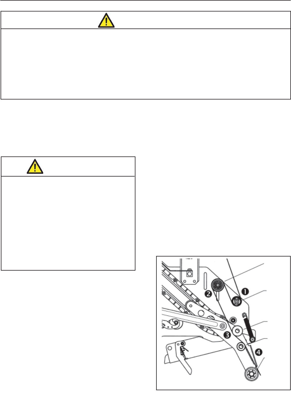
10
It is recommended that the detailed instructions and
sketches in this manual be referred to the fi rst few
times the taping head is loaded/threaded until the
operator becomes thoroughly familiar with the tape
loading operation.
Note – Remove tape roll before removing taping
head from machine to minimize weight.
Operation (Continued)
Figure 3-3
Insert threading needle through rollers in direction
indicated by arrows.
5. Pull the threading needle down until the tape
travels between the apply plate and the ears of
the apply arm (Position 4) until it extends past
the applying roller. When properly threaded the
adhesive side of the tape should be facing the
knurled rollers at position 2 and also position 3.
6. Cut away any excess tape.
Important – Do not cut against the apply roller -
roller damage could occur.
Tape Loading – Lower Taping Head
1. Remove the lower taping head from the
conveyor bed or associated equipment and
place it a convenient working position.
2. The lower taping head is loaded and threaded
in the same manner as the upper head. Follow
the upper taping head tape loading/threading
procedure.
Tape Loading – Upper Taping Head
1. Place the upper taping head in a convenient
working position.
2. Use Figures 3-3 to 3-5 and tape threading la-
bel. Position the tape supply roll so the adhesive
side of tape is facing the front of the taping head
as it is pulled from the supply roll.
3. Attach the threading needle to the end of the
roll. Guide the threading needle around the wrap
roller (Position 1) then back around the one-way
tension roller (Position 2).
4. Continue pulling the threading needle down and
guide it between the two rollers on the apply arm
(Position 3).
• To reduce the risk associated with shear, pinch, and entanglement hazards:
− Turn air and electrical supplies off on associated equipment before performing any adjustments,
maintenance, or servicing the machine or taping heads
− Never attempt to work on the taping heads or load tape when the box drive system is running
• To reduce the risk associated with sharp blade hazards:
− Keep hands and fi ngers away from tape cutoff blades under orange blade guards.
The blades are extremely sharp
WARNING
• To reduce the risk associated with
muscle strain:
− Use proper body mechanics when
removing or installing taping heads that
are moderately heavy or may be
considered awkward to lift
• To reduce the risk associated with impact
hazards:
− Place the taping head on a smooth level
surface when maintaining or servicing this
equipment
CAUTION
Figure 3-3 – Tape Loading/Threading
Tension
Wrap
Roller
Knurled
Roller
Wrap
Roller
One-Way
Tension
Roller
Applying
Roller
AccuGlide 3 Taping Head - 2" 2009 February
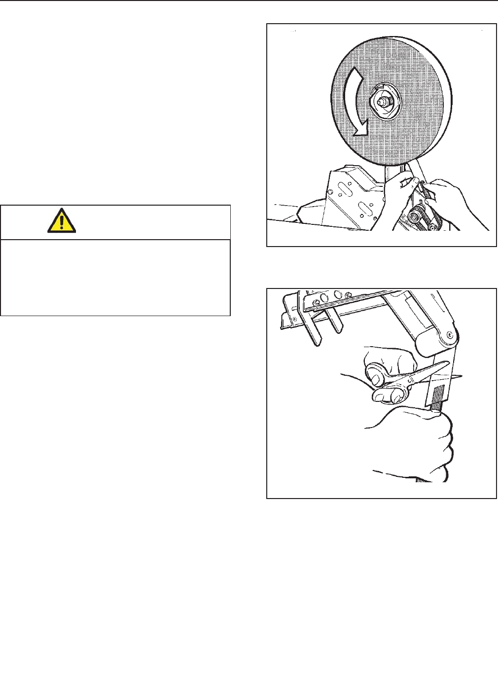
11
Operation (Continued)
Manually turn tape roll to create slack tape while
pulling threading needle through tape applying
mechanism until needle is through and tape is in
alignment with applying roller.
Excess tape can be cut with a scissors at applying
roller.
Figure 3-4
Place tape roll on tape drum to dispense tape with
adhesive side forward. Seat tape roll fully against
back fl ange of drum. Adhere tape lead end to
threading needle as shown.
Figure 3-4 – Tape Loading/Threading
Figure 3-5 – Tape Loading/Threading
WARNING
• To reduce the risk associated with sharp
blade hazards:
- Keep hands and fi ngers away from tape
cutoff blades under orange blade guards.
The blades are extremely sharp.
AccuGlide 3 Taping Head - 2" 2009 February
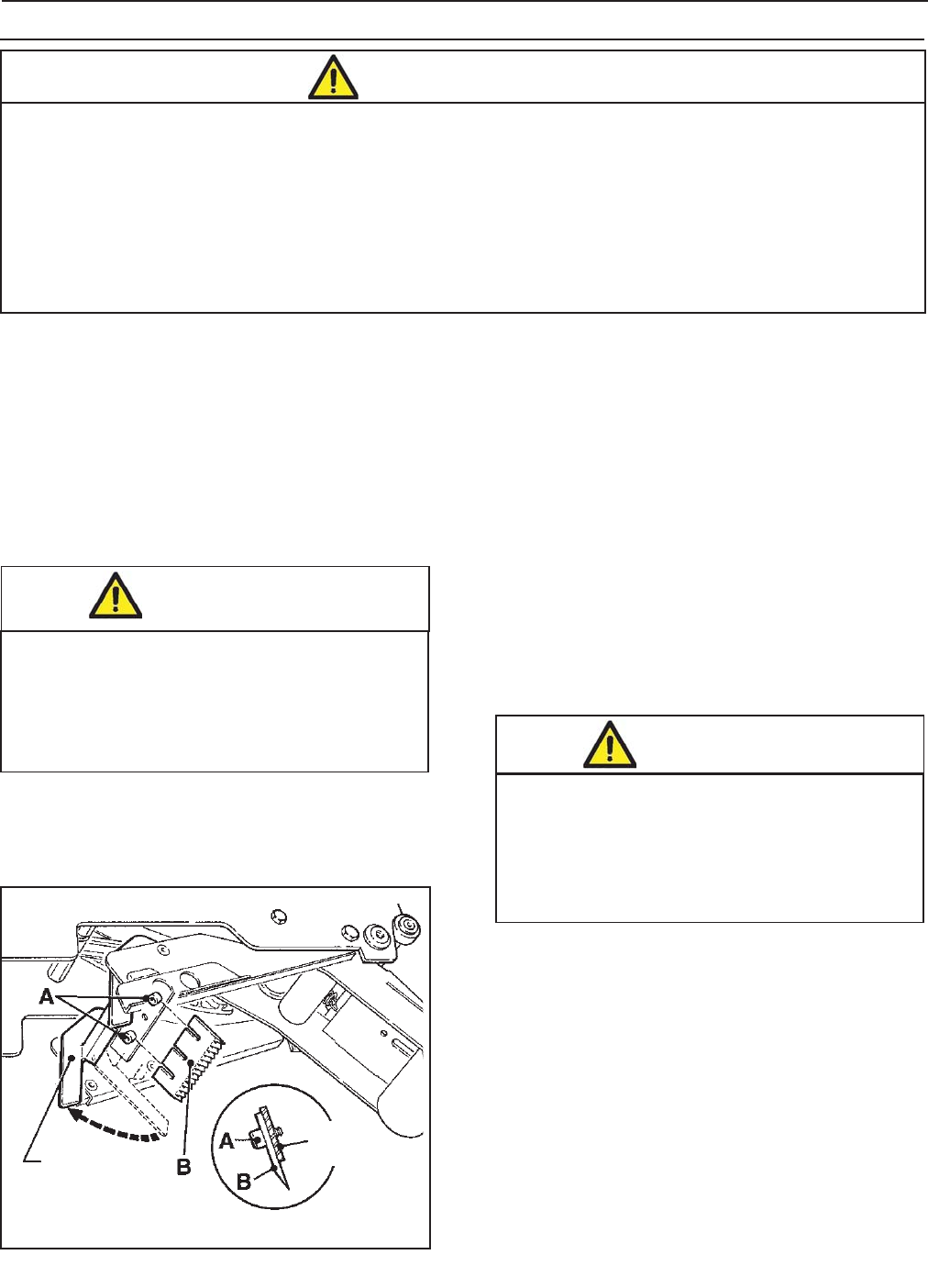
12
3. Bottom the blade slots against the screws. (This
will position the blade at the correct angle.)
Tighten the blade screws to secure the blade.
Blade Guard
The blade guard covers the blade whenever a box
is not being taped. Periodically check to be sure the
blade guard is functioning properly and returning to
cover the blade. Replace any defective parts.
Blade Oiler Pad
The taping heads are equipped with a felt oiler pad
that has been pre-lubricated at the factory to
provide a fi lm of oil on the cutting edge of the blade
to reduce adhesive build-up. Apply SAE #30 non-
detergent oil as needed. Saturate felt oiler pad.
Should tape adhesive build-up occur on blade,
carefully wipe clean with an oily cloth.
Maintenance
• To reduce the risk associated with shear, pinch, and entanglement hazards:
− Turn air and electrical supplies off on associated equipment before performing any adjustments,
maintenance, or servicing the taping heads
− Never attempt to work on the taping head or load tape while the box drive system is running
• To reduce the risk associated with sharp blade hazards:
− Keep hands and fi ngers away from tape cutoff blades under orange blade guards.
The blades are extremely sharp
WARNING
Note – Check the blade position to insure proper
clearance between blade and guard by slowly
pivoting the blade guard back.
WARNING
• To reduce the risk associated with sharp
blade hazards:
- Keep hands and fi ngers away from tape
cutoff blades under orange blade guards.
The blades are extremely sharp WARNING
• To reduce the risk associated with sharp
blade hazards:
- Keep hands and fi ngers away from tape
cutoff blades under orange blade guards.
The blades are extremely sharp
Figure 4-1 – Blade Replacement (Maintenance continued on next page.)
Knife
Guard
Knife
Holder
AccuGlide 3 Taping Head - 2" 2009 February
The AccuGlide™ 3 Upper and Lower Taping
Heads - 2 Inch has been designed for long, trouble
free service. The taping head will perform best when
it receives routine maintenance and cleaning. Taping
head components that fail or wear excessively should
be promptly repaired or replaced to prevent damage to
other portions of the head or to the product.
Blade Replacement, Upper and Lower Taping
Heads (Figure 4-1)
1. Loosen, but do not remove, the blade screws (A).
Remove and discard old blade.
2. Mount the new blade (B) with the beveled side
away from the blade holder.
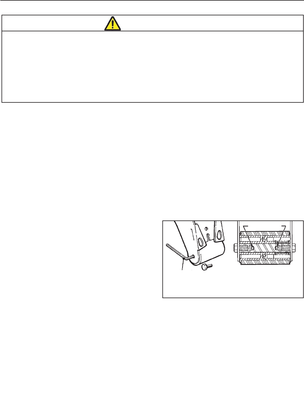
13
Maintenance (Continued)
Applying/Buff ng Roller Replacement
Replacing roller requires removal of shaft and
mounting screws. With no area on the shaft to grip,
the shaft often turns when attempting to remove the
second screw.
To ease removal of second screw, a 5mm hex
socket has been provided at the bottom of the
threads in both ends of the shaft. Insert a 5mm
hex key wrench into this socket after removing one
screw to hold the shaft for removal of the second
screw. See Figure 4-2.
Cleaning
Regular slotted containers produce a great deal
of dust and paper chips when conveyed through
taping heads. If this dust is allowed to build-up
on the heads, it can cause wear on the moving
parts. Excessive dirt build-up should be wiped
off with a damp cloth. Cleaning should be done
once per month, depending on the number and
type of boxes used. If the boxes used are dirty, or
if the environment in which the heads operate is
dusty, cleaning on a more frequent basis may be
necessary.
Note – Never attempt to remove dirt from taping
heads by blowing it out with compressed
air. This can cause the dirt to be blown inside
the components onto sliding surfaces.
Dirt in these areas can cause serious
equipment damage. Never wash down or
subject taping heads to conditions causing
moisture condensation on components.
Serious equipment damage could result.
• To reduce the risk associated with shear, pinch, and entanglement hazards:
− Turn air and electrical supplies off on associated equipment before performing any
adjustments, maintenance, or servicing the taping heads
− Never attempt to work on the taping head or load tape while the box drive system is running
• To reduce the risk associated with sharp blade hazards:
− Keep hands and fi ngers away from tape cutoff blades under orange blade guards.
The blades are extremely sharp
WARNING
Figure 4-2 – Roller Shaft Section View
5mm Hex
Key Wrench
Section View of
Roller/Shaft
Hex Socket
AccuGlide 3 Taping Head - 2" 2009 February
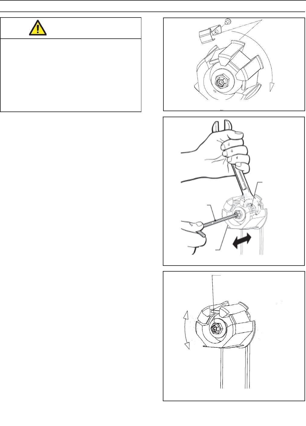
14
Tape Drum Friction Brake – Figure 5-3
The tape drum friction brake on each taping head is
pre-set for normal operation to prevent tape roll over
travel. Should tension adjustment be required, turn
the self-locking nut on the shaft to vary compression
of the spring. Turn the nut clockwise to increase the
braking force, and counterclockwise to decrease the
braking force. Adjust brake to minimum tension to
prevent excessive tape roll over travel.
Tape Latch Alignment – Figure 5-1
The Latching tape drum assembly is pre-set to
accommodate 48mm [2 inch] wide tape. The tape
drum assembly is adjustable to provide alignment of
narrower tapes.
To move the latch to a position that corresponds to a
new tape core width (Figure 5-1):
1. Remove screw from the latch.
2. Move to the latch to the position that
corresponds to the tape core width.
3. Replace screw in the new latch location.
To adjust or center the tape width on the center line
of the taping head, and therefore box center seam,
(Figure 5-2):
1. Loosen the locking hex nut behind tape drum
bracket on tape drum shaft. Use an adjustable
wrench or 25mm open end wrench.
2. Turn tape drum shaft in or out to center the tape
web (use 5mm hex wrench).
3. Tighten locking hex nut to secure the adjustment.
No other components require adjustment for tape
web alignment.
Note – Excess braking force will cause poor tape
application and may lead to tape tabbing
on the trailing tape leg.
Adjustments
WARNING
• To reduce risk associated with shear,
pinch, and entanglement hazards:
- Turn air and electrical supplies off
associated equipment before performing
any adjustments, maintenance, or
servicing the machine or taping heads.
- Never attempt to work on the taping head
or load tape while the box drive system is
running. Figure 5-1 – Tape Latch Alignment
Figure 5-2 – Tape Web Alignment
Figure 5-3 – Tape Drum Friction Brake
(Adjustments continued on next page.)
5mm Hex
Wrench
Shaft
25mm Hex
Wrench
Adjustment Nut,
Tape Drum Brake
AccuGlide 3 Taping Head - 2" 2009 February
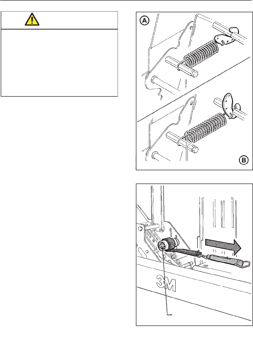
15
Adjustments (Continued)
Applying Mechanism Spring
To obtain access to the spring, remove the taping
head cover (four mounting screws). Replace cover
when fi nished.
The applying mechanism spring, shown in
Figures 5-4A and 5-4B, controls applying and
buffi ng roller pressure on the box and returns
the mechanism to the reset position. The spring
pressure is pre-set, as shown in Figure 5-4A for
normal operation, but is adjustable.
If a tape gap appears on the trailing surface of the
box increase spring pressure. If the front of the box
is being crushed by the applying roller decrease
spring pressure.
Removing the spring end loop from the spring holder
and placing loop in other holes provided, as shown
in Figure 5-4B, will adjust the spring pressure.
To Adjust Tension:
1. Wrap a cord or small strap (non-adhesive) 4-6
turns around the tension roller.
2. Attach a spring scale to the end of the cord or
strap.
3. Turn the adjusting nut with the socket wrench
provided, until a force of approximately 0.5 kg to
0.9 kg [1 to 2 lbs.] is required to turn the roller by
pulling on the spring scale.
One-Way Tension Roller
Figure 5-5
The one-way tension roller is factory set. When
replacing this assembly, the roller must have
approximately 0.5 kg to 0.9 kg [1 to 2 lbs.] force
when turning.
Figure 5-4 – Applying Mechanism Spring
Figure 5-5 – One-Way Tension Roller
WARNING
• To reduce risk associated with shear,
pinch, and entanglement hazards:
- Turn air and electrical supplies off
associated equipment before
performing any adjustments,
maintenance, or servicing the machine
or taping heads.
- Never attempt to work on the taping
head or load tape while the box drive
system is running.
(Adjustments continued on next page.)
0.5 - 0.9kg
[1 - 2 lbs.]
Adjusting Nut
AccuGlide 3 Taping Head - 2" 2009 February
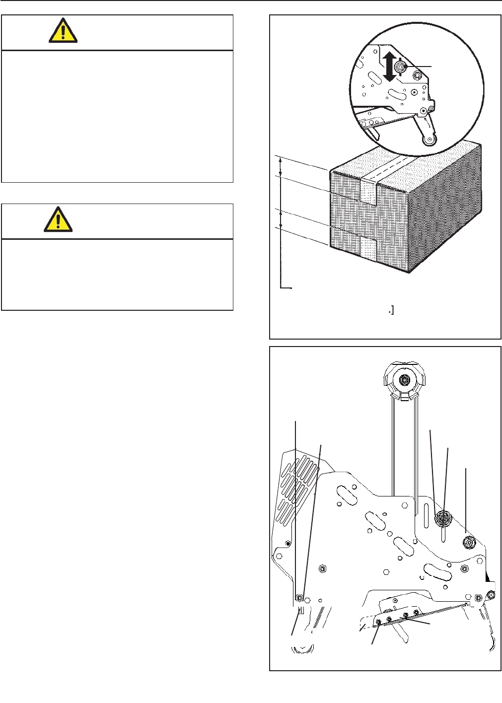
16
Adjustments (Continued)
Tape Leg Length
1. Remove and retain two hex head screws and
remove the brush from normal position “A” on
side frame.
2. Remount and secure brush in position “A-A”
on side frame forward of normal location using
original fasteners.
3. Remove cut-off bracket extensions from position
"B".
4. Remount cut-off bracket extensions in forward
position “B-B”.
5. Remove and retain the one-way tension roller
assembly from slot “C” in frame.
6. Remount tension roller assembly near top of slot
“C-C” in frame using original fasteners.
7. Adjust tension roller according to "Leading Tape
Leg Length Adjustment" above.
Leading Tape Leg Length Adjustment – Figure 5-6
The one-way tension roller position is adjustable to
control the leading tape leg length.
Moving this roller farther away from the box top or
bottom surface will decrease the leading leg length.
Moving it closer to the box top or bottom surface will
increase the leading leg length.
Changing Tape Leg Length from 70 to 50mm
[2-3/4
to 2 Inches] – Figure 5-7
Note – When changing tape leg length, both
upper and lower heads must be adjusted
to apply the same leg lengths.
Figure 5-6 – Leading Tape Leg Length
Figure 5-7 – Changing Tape Leg Length
WARNING
• To reduce the risk associated with
shear, pinch, and entanglement
hazards:
- Turn air and electrical supplies off
associated equipment before perform-
ing any adjustments, maintenance, or
servicing the machine or taping heads.
- Never attempt to work on the taping
head or load tape while the box drive
system is running
WARNING
• To reduce the risk associated with sharp
blade hazards:
- Keep hands and fi ngers away from tape
cutoff blades under orange blade guards.
The blades are extremely sharp
One-Way
Tension
Roller
Tape Leg
50 or 70mm ± 6mm
[2 or 2-3/4in. ± 1/4in.
One-Way
Tension Roller
Assembly
Slot C-C
Slot C
Position A-A
Position A
Position B-B
Position B
Brush
Cut-Off
Bracket
Extension
AccuGlide 3 Taping Head - 2" 2009 February

17
Troubleshooting
Cause
The tape is threaded incorrectly
The tape tension is too low
The knurled roller drags
Tape tracks to one side or drags
on the support tabs of applying
frame
The one-way tension roller is not
correctly positioned
Taping head is not set up properly
The blade is dull and/or has
broken teeth
Tape tension is insuffi cient
Adhesive has built up on the blade
The blade is not positioned
properly
The blade is dry
The blade is in backwards
One or both cutter springs are
missing or stretched
Tension roller surface is not fully
contacting the taping head frame
Correction
The tape must go around the wrap
roller before going around the
one-way tension roller
Adjust the one-way tension roller
Check for adhesive build-up
between the knurled roller and its
shaft. Clean and lubricate shaft.
Remove all lubricant from roller
surfaces.
Adjust the tape web alignments
Position the roller in its mounting
slot so that the tape extends just
beyond the center line of the
applying roller
Check leg length adjustments
Replace the blade
Increase tape tension by adjusting
the one-way tension roller
Clean and adjust the blade
Make sure the blade is bottomed
out against the mounting bolts
Lubricate the blade oiler pad on
the blade guard
Mount the blade so that the
beveled edge is away from the
entrance of the head
Replace the defective spring(s)
Make sure one-way bearing is
below the surface of the tension
roller. If not, press bearing further
into roller or replace roller.
Troubleshooting Guide
Problem
The tape leg on the front of the
case is too long
The blade does not cut tape or the
tape end is jagged or shredded
AccuGlide 3 Taping Head - 2" 2009 February

18
Problem
Tape is tabbing on the trailing leg
on the back of the box
The tape end does not stay in
application position in front of the
applying roller
Tape not centered on box seam
Cause
There is excess tension on the
tape drum assembly and/or the
one-way tension roller assembly
Rollers in the tape path do not
rotate freely
The blade is not cutting tape
properly
The tape is threaded incorrectly
Applying mechanism spring has
too little tension
The tape is incorrectly threaded
Flanged knurled roller overruns on
return of applying mechanism to
its rest position
Applying roller overruns on return
of applying mechanism to its rest
position
The one-way tension roller is not
correctly positioned
The one-way tension roller is
defective
Tape drum not centered
Centering guides not centered
Box fl aps not of equal length
Correction
Adjust the one-way tension roller
and/or the tape drum assembly
Clean adhesive deposits from
the surface, ends, and shafts of
the rollers. Then lubricate roller
shafts. Remove all lubricant from
roller surfaces.
Refer to tape cutting problems
Re thread the tape
Move spring hook to next tighter
hole
Re thread the tape
Adjust tension roller position in
mounting slot to lengthen tape leg
There should be a slight drag
when rotating the applying roller.
If not, check friction springs and/
or friction pins and replace if
necessary
Position roller in it mounting slot
so that tape end extends beyond
center line of applying roller
Replace the one-way tension
roller
Reposition tape drum
Adjust centering guides
Check box specifi cations
Troubleshooting Guide
Troubleshooting (Continued)
AccuGlide 3 Taping Head - 2" 2009 February

19
Spare Parts/Service Information
Recommended Spare Parts
Listed are a set of spare parts that will periodically require replacement due to normal wear. These parts should
be ordered to keep the taping heads in production:
AccuGlide™ 3 Upper Taping Head - 2 inch
Qty. Ref. No. Part Number Description
4 10925-22 78-8076-4500-3 Stud – Mounting
1 10919-10 78-8137-3311-6 Spring – Upper Extension
1 10921-2 78-8017-9173-8 Blade – 65mm/2.56 Inch
2 10921-12 78-8052-6602-6 Spring – Cutter
1 - 78-8076-4726-4 Tool – Tape Threading
AccuGlide™
3 Lower Taping Head - 2 inch
Qty. Ref. No. Part Number Description
1 10921-2 78-8017-9173-8 Blade – 65mm/2.56 Inch
2 10921-12 78-8052-6602-6 Spring – Cutter
4 10924-22 78-8076-4500-3 Stud – Mounting
1 10920-10 78-8137-3312-4 Spring – Lower Extension
1 - 78-8076-4726-4 Tool – Tape Threading
In addition to the above set of spare parts supplied with the taping head, it is suggested that the following spare
parts be maintained which will require replacement under normal wear of the taping head.
Qty. Ref. No. Part Number Description
1 10922-15 78-8057-6179-4 Roller – Applying
1 10919/10389-5 78-8057-6178-6 Roller – Buffi ng
1 10921-18 78-8113-7030-9 Spring – Torsion
Replacement Parts and Service
Refer to the fi rst page of this instruction manual “Replacement Parts and Service Information".
AccuGlide 3 Taping Head - 2" 2009 February

20
Replacement Parts Illustrations and Parts Lists
AccuGlide™ 3 Upper Taping Head - 2 inch, Type 10800
AccuGlide™ 3 Lower Taping Head - 2 inch, Type 10800
1. Refer to the Taping Head Assemblies Figure to fi nd all the parts illustrations identifi ed by f gure numbers.
2. Refer to the fi gure or fi gures to determine the individual parts required and the parts reference number.
3 . The replacement parts list, that follows each illustration, includes the part number and part description
for the parts in that illustration.
Note – The complete description has been included for standard fasteners and some commercially
available components. This has been done to allow obtaining these standard parts locally, should
the customer elect to do so.
4. Refer to the fi rst page of this instruction manual "Replacement Parts and Service Information" for
replacement parts ordering information.
IMPORTANT – Not all the parts listed are normally stocked items. Some parts or assemblies shown
are available only on a special order basis. Contact 3M/Tape Dispenser Parts to
confi rm item availability.
AccuGlide 3 Taping Head - 2" 2009 February
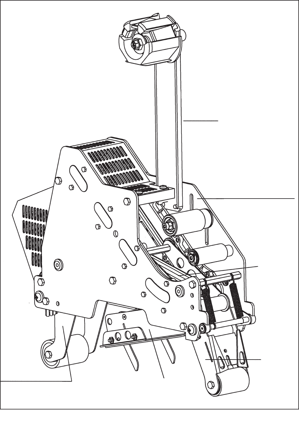
21
Taping Head Assemblies - AccuGlide™ 3 Upper and Lower Taping Heads - 2 Inch
Figure 10919 (Upper)
Figure 10920 (Lower) Figure 10921
Figure
10922
Figure
10923
Figure 10925 (Upper)
Figure 10924 (Lower)
Figure 10401
AccuGlide 3 Taping Head - 2" 2009 February
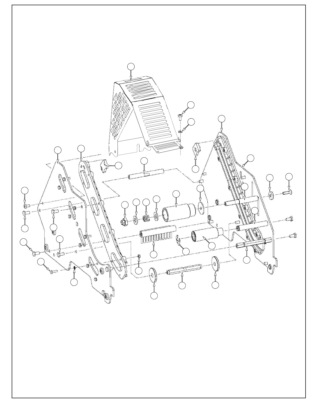
27
28
1
20
21
29 29
13 13
9
13
19 17 18 17 16 15 11
12
8
27
26
2 4
3
25 24
5
13
23
7 23
10
22
Figure 10925 – Upper Head
AccuGlide 3 Taping Head - 2" 2009 February
33
6

23
Figure 10925 – 2" Upper Head
Ref. No. 3M Part No. Description
10925-1 78-8137-3294-4 Frame – Tape Mount Upper Assembly
10925-2 78-8137-3295-1 Frame – Front Upper Assembly
10925-3 78-8068-4143-9 Guide – #1
10925-4 78-8068-4144-7 Guide – #2
10925-5 78-8060-7818-0 Screw – Hex Hd, M4 x 12
10925-6 78-8010-7416-8 Nut – Hex Jam, M4
10925-7 78-8070-1251-9 Spacer – Spring
10925-8 78-8137-3298-5 Shaft - Pivot 90mm
10925-9 78-8052-6560-6 Spacer – Front
10925-10 78-8060-7936-0 Brush Assembly
10925-11 78-8052-6564-8 Shaft – Tension Roller
10925-12 78-8052-6568-9 Shaft – Wrap Roller
10925-13 26-1003-5829-5 Screw – Hex Hd, M6 x 12
10925-15 78-8100-1009-6 Washer – Special
10925-16 78-8052-6565-5 Roller – Top Tension
10925-17 26-1004-5510-9 Washer – Plain, M10
10925-18 78-8052-6567-1 Spring – Compression
10925-19 78-8017-9077-1 Nut – Self Locking, M10 x 1
10925-20 78-8052-6569-7 Roller – Wrap
10925-21 26-1000-1613-3 Ring – Retaining, Tru-Arc #1-420-0120-100
10925-22 78-8076-4500-3 Stud – Mounting
10925-23 78-8076-5242-1 Stop – Cut-Off Frame
10925-24 78-8060-8179-6 Screw – Flat Hd Hex, M6 x 20
10925-25 78-8076-5477-3 Washer – Special /6.5 x 20 x 4
10925-26 78-8137-3299-3 Guard – Head
10925-27 78-8060-8087-1 Screw – M5 x 10
10925-28 78-8005-5741-1 Washer – Flat, M5
10925-29 78-8133-9615-3 Bumper
10925-30 78-8133-9605-4 Label – Threading, English Language
AccuGlide 3 Taping Head - 2" 2009 February
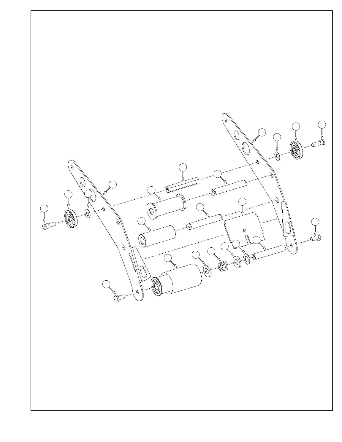
2
1
5
4
6
15
1412 13 12 11 10
4
7
3
15
8
16
9
9
8 16
24
AccuGlide 3 Taping Head - 2" 2009 February
Figure 10922 – Upper and Lower Heads

25
Figure 10922 – 2" Upper and Lower Heads
Ref. No. 3M Part No. Description
10922-1 78-8133-9509-8 Applying Arm #1
10922-2 78-8133-9510-6 Applying Arm #2
10922-3 78-8070-1221-2 Plate – Tape
10922-4 78-8070-1309-5 Shaft Roller
10922-5 78-8070-1367-3 Roller – Knurled Assembly
10922-6 78-8070-1266-7 Roller – Wrap
10922-7 78-8052-6580-4 Spacer
10922-8 78-8017-9082-1 Bearing – Special, 30 mm
10922-9 78-8017-9106-8 Screw – Bearing Shoulder
10922-10 78-8052-6575-4 Shaft – Roller
10922-11 78-8017-9074-8 Washer – Nylon, 15 mm
10922-12 26-1004-5510-9 Washer – Friction
10922-13 78-8052-6567-1 Spring – Compression
10922-14 78-8137-1438-9 Assembly– Applying Roller
10922-15 26-1003-5829-5 Screw – Hex Hd, M6 x 12
10922-16 78-8094-6151-6 Washer - Flat, 6.5 ID x 15 OD x 0.5 Thk
AccuGlide 3 Taping Head - 2" 2009 February
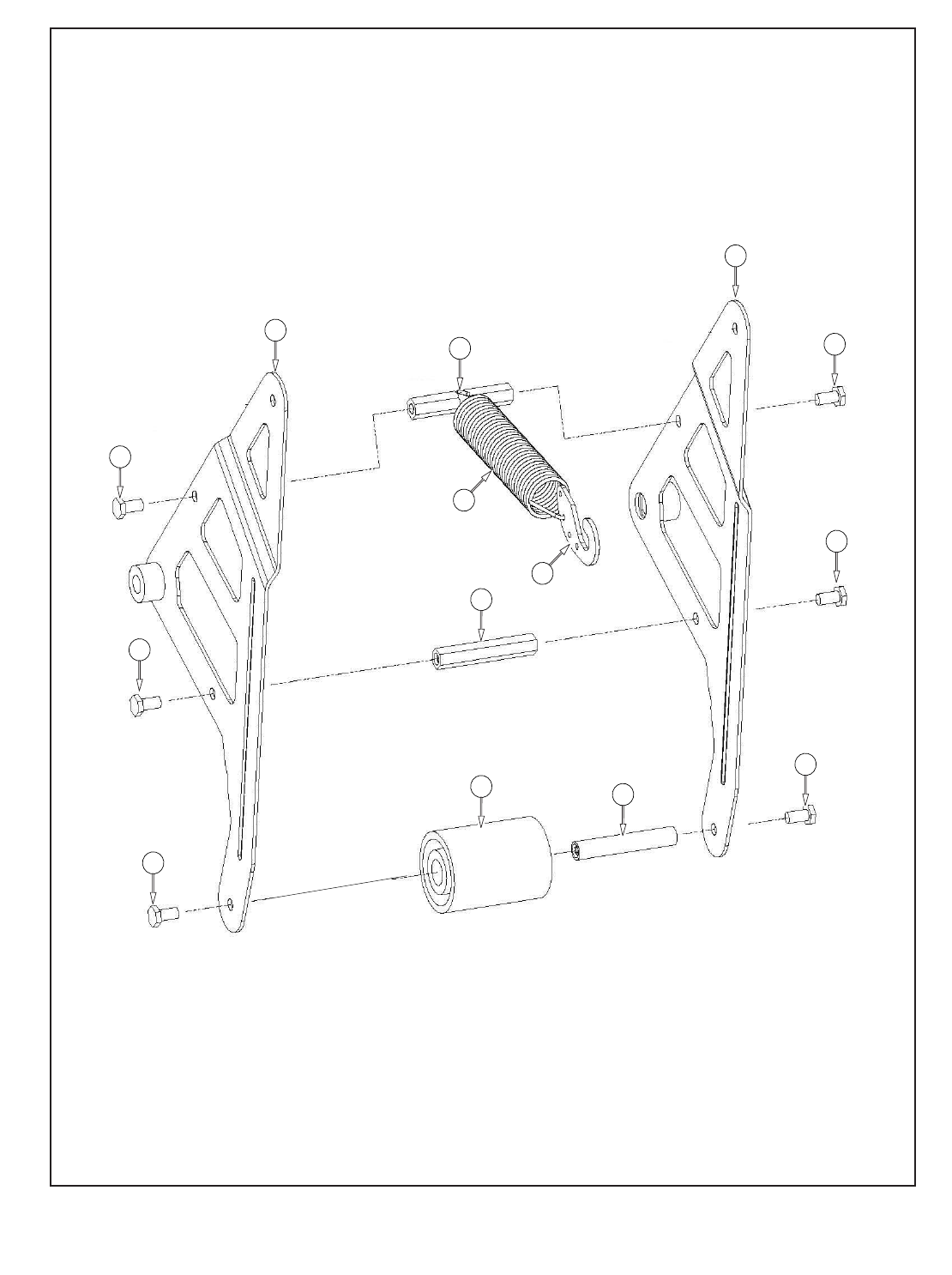
8
9
6
4 3
7
7
7
7
7
7
1
2 5
26
Figure 10919 – Upper Head
AccuGlide 3 Taping Head - 2" 2009 February

27
Figure 10919 – 2" Upper Head
Ref. No. 3M Part No. Description
10919-1 78-8137-3300-9 Buffi ng Arm – Sub Assembly
10919-2 78-8137-3301-7 Buffi ng Arm – Sub Assembly
10919-3 78-8052-6575-4 Shaft – Roller
10919-4 78-8137-1398-5 Roller - Buffi ng Assembly
10919-5 78-8070-1220-4 Spacer – Spring
10919-6 78-8052-6580-4 Spacer
10919-7 26-1003-5829-5 Screw – Hex Hd, M6 x 12
10919-8 78-8137-3311-6 Spring – Upper (100 fpm)
10919-9 78-8070-1244-4 Holder – Spring
AccuGlide 3 Taping Head - 2" 2009 February
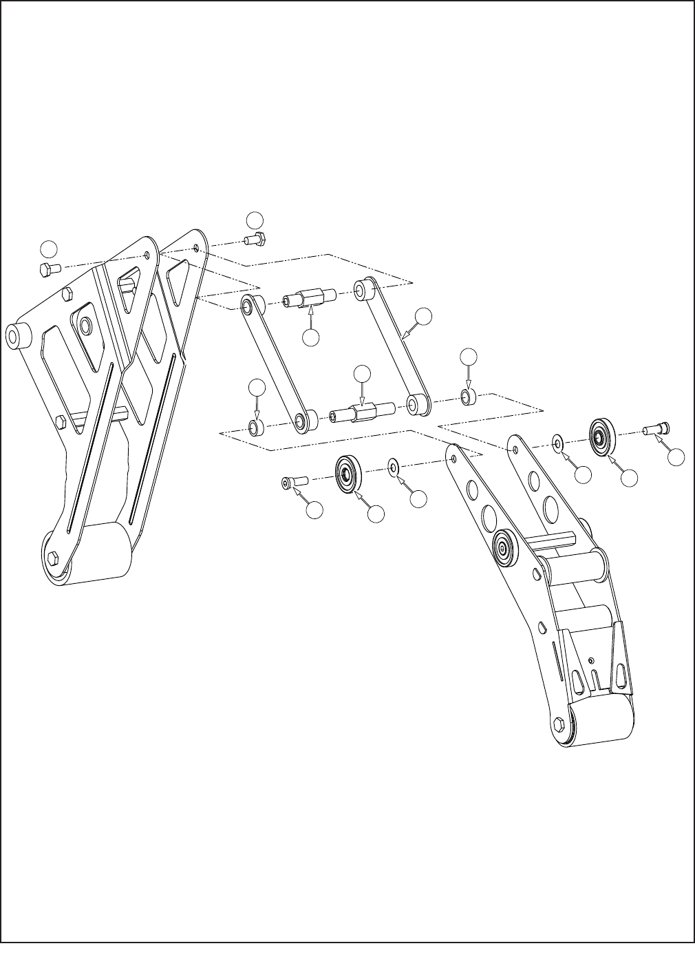
1
5 4 9
9 4
5
3
8
7
7
28
Figure 10923 – Upper and Lower Heads
AccuGlide 3 Taping Head - 2"2009 August
6
6

29
Ref. No. 3M Part No. Description
10923-1 78-8137-3302-5 Link – Assembly
10923-3 78-8137-3304-1 Shaft – Pivot, Buffi ng
10923-4 78-8017-9082-1 Bearing – Special 30 mm
10923-5 78-8017-9106-8 Screw – Bearing Shoulder
10923-6 26-1003-5829-5 Screw – Hex Hd, M6 x 12
10923-7 78-8137-3305-8 Spacer – Applying Pivot
10923-8 78-8137-3306-6 Shaft – Pivot, Applying
10923-9 78-8137-6151-6 Washer - Flat, 6.5 ID x 15 OD x 0.5 Thk
Figure 10923 – 2" Upper and Lower Heads
AccuGlide 3 Taping Head - 2" 2009 February
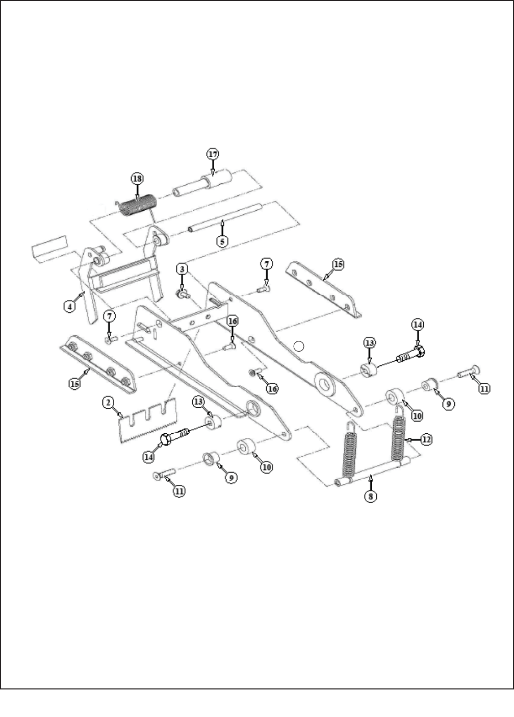
30
Figure 10921 – Upper and Lower Heads
AccuGlide 3 Taping Head - 2" 2009 August
1

31
Figure 10921 – 2" Upper and Lower Heads
Ref. No. 3M Part No. Description
10921-1 78-8137-3307-4 Frame – Cut-Off Weldment
10921-2 78-8017-9173-8 Blade – 65 mm/2.56 Inch
10921-3 26-1003-8596-7 Screw - Hex Hd M5 x 8 w/ Ext. Tooth Lockwasher
10921-4 78-8070-1371-5 Blade Guard Assembly – W/English Language Label
10921-5 78-8052-6597-8 Shaft – Blade Guard
10921-7 26-1005-4758-2 Screw – Flat Hd, Soc Dr, M4 x 10
10921-8 78-8017-9135-7 Shaft – Spacer
10921-9 78-8052-6600-0 Spacer
10921-10 78-8070-1269-1 Bumper
10921-11 26-1005-4757-4 Screw – Flat Hd, Soc Dr, M5 x 20
10921-12 78-8052-6602-6 Spring – Cutter
10921-13 78-8017-9132-4 Pivot – Cutter Lever
10921-14 26-1003-5828-7 Screw – Spec, Hex Hd, M6 x 10
10921-15 78-8137-3308-2 Slide – Extension
10921-16 26-1008-6574-5 Screw – Flat Hd, Phil Dr, M4 x 10
10921-17 78-8113-7031-7 Bushing – 58.5mm Long
10921-18 78-8113-7030-9 Spring – Torsion
10921-19 78-8070-1335-0 Label – Warning, English
AccuGlide 3 Taping Head - 2" 2009 February
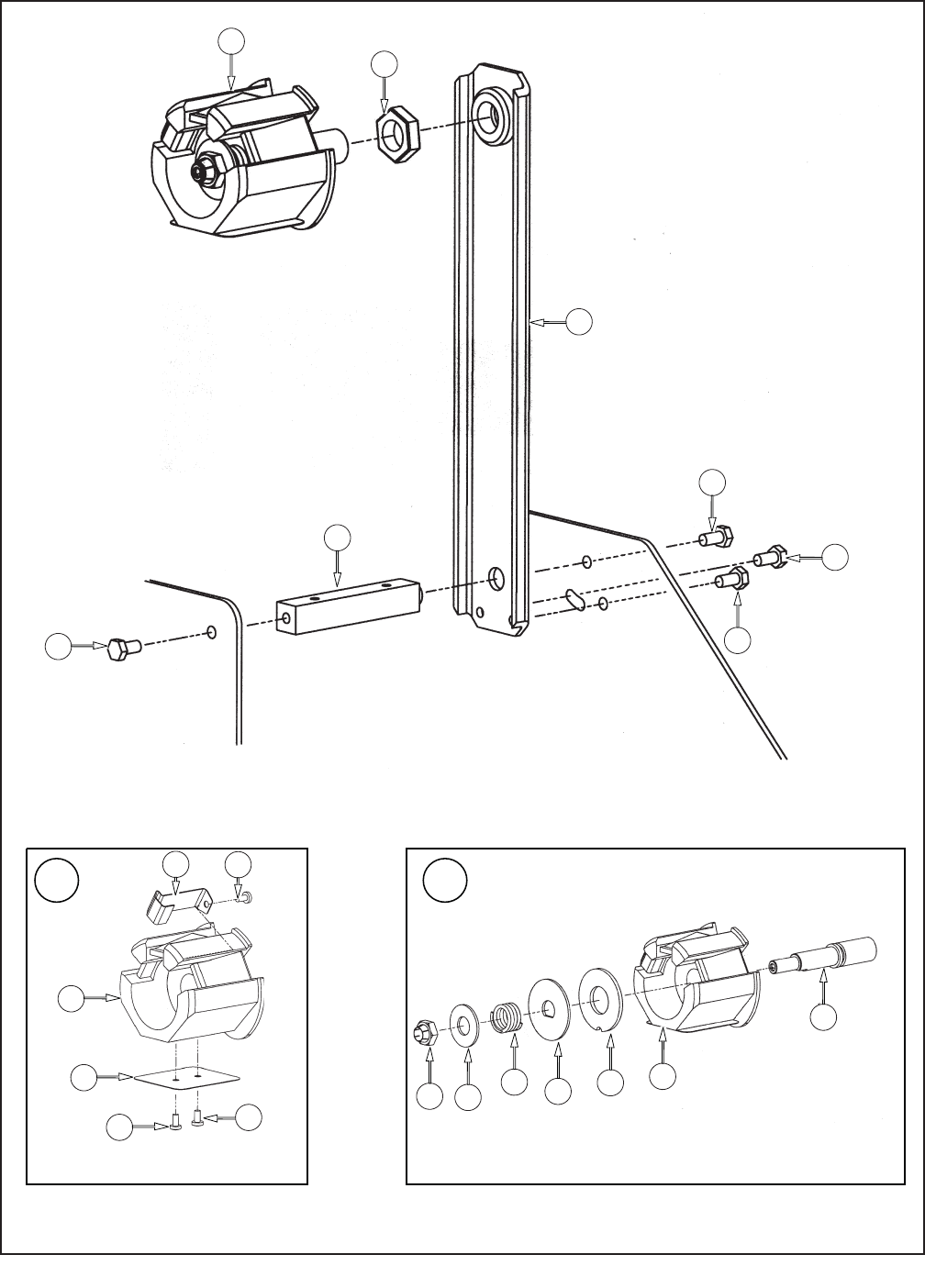
32
Figure 10401 – Upper and Lower Heads
AccuGlide 3 Taping Head - 2" 2009 February
414
11 15
10 9 8 4
2
7
16
5
6
7 7
14
3
1
13
13
12
13
13

33
Figure 10401 – 2" Latch Upper and Lower Heads
Ref. No. 3M Part No. Description
10401-1 78-8070-1395-4 Bracket – Bushing Assembly
10401-2 78-8076-4519-3 Shaft – Tape Drum, 50 mm
10401-3 78-8017-9169-6 Nut – M18 x 1
10401-4 78-8098-8827-0 Tape Drum Sub Assembly – 2 Inch Wide
10401-5 78-8098-8749-6 Tape Drum
10401-6 78-8098-8817-1 Leaf Spring
10401-7 26-1002-5753-9 Screw – Self Tapping
10401-8 78-8060-8172-1 Washer – Friction
10401-9 78-8052-6271-0 Washer – Tape Drum
10401-10 78-8100-1048-4 Spring – Core Holder
10401-11 78-8017-9077-1 Nut – Self Locking, M10 x 1
10401-12 78-8100-1046-8 Spacer – Bracket
10401-13 26-1003-5829-5 Screw – Hex Hd, M6 x 12
10401-14 78-8098-8814-8 Tape Drum Assembly – 2 Inch Head
10401-15 26-1004-5510-9 Washer – Plain, M10
10401-16 78-8098-8816-3 Latch – Tape Drum
AccuGlide 3 Taping Head - 2" 2009 February
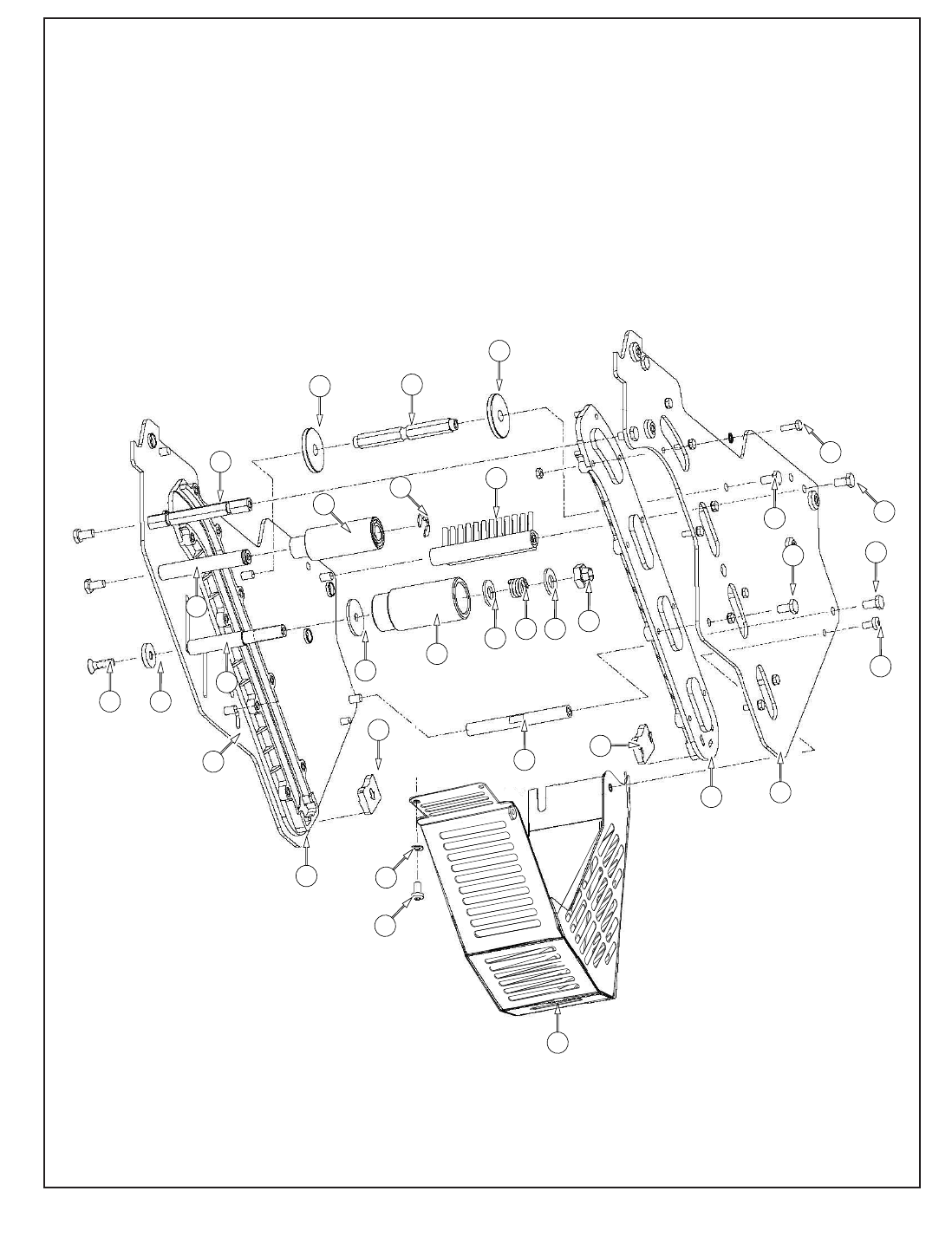
27
28
1
20 21
29
29
13
13
9
13
19
17 18
17
16
15
11
12
27
26
2
4
3
25 24
5
13
23
7
23
10
8
Figure 10924 – Lower Head
34
AccuGlide 3 Taping Head - 2" 2009 February

35
Figure 10924 – 2" Lower Head
Ref. No. 3M Part No. Description
10924-1 78-8137-3296-9 Frame – Tape Mount Lower Assembly
10924-2 78-8137-3297-7 Frame – Front Lower Assembly
10924-3 78-8068-4144-7 Guide – #2
10924-4 78-8068-4143-9 Guide – #1
10924-5 78-8060-7818-0 Screw – Hex Hd, M4 x 12
10924-6 78-8010-7416-8 Nut – Hex, M4
10924-7 78-8070-1251-9 Spacer – Spring
10924-8 78-8054-8764-8 Spacer – 10 x 10 x 90 mm
10924-9 78-8052-6560-6 Spacer – Front
10924-10 78-8060-7936-0 Brush Assembly
10924-11 78-8052-6564-8 Shaft – Tension Roller
10924-12 78-8052-6568-9 Shaft – Wrap Roller
10924-13 26-1003-5829-5 Screw – Hex Hd, M6 x 12
10924-15 78-8100-1009-6 Washer – Special
10924-16 78-8052-6606-7 Roller – Tension Bottom
10924-17 26-1004-5510-9 Washer – Plain, M10
10924-18 78-8052-6567-1 Spring – Compression
10924-19 78-8017-9077-1 Nut – Self Locking, M10 x 1
10924-20 78-8052-6569-7 Roller – Wrap
10924-21 26-1000-1613-3 Ring – Retaining, Tru-Arc #1-420-0120-100
10924-22 78-8076-4500-3 Stud – Mounting
10924-23 78-8076-5242-1 Stop – Cut-Off Frame
10924-24 78-8060-8179-6 Screw – Flat Hd Hex, M6 x 20
10924-25 78-8076-5477-3 Washer – Special /6.5 x 20 x 4
10924-26 78-8137-3299-3 Guard – Head
10924-27 78-8060-8087-1 Screw – M5 x 10
10924-28 78-8005-5741-1 Washer – Flat, M5
10924-29 78-8133-9615-3 Bumper
10924-30 78-8133-9606-2 Label – Threading, English Language
AccuGlide 3 Taping Head - 2" 2009 February
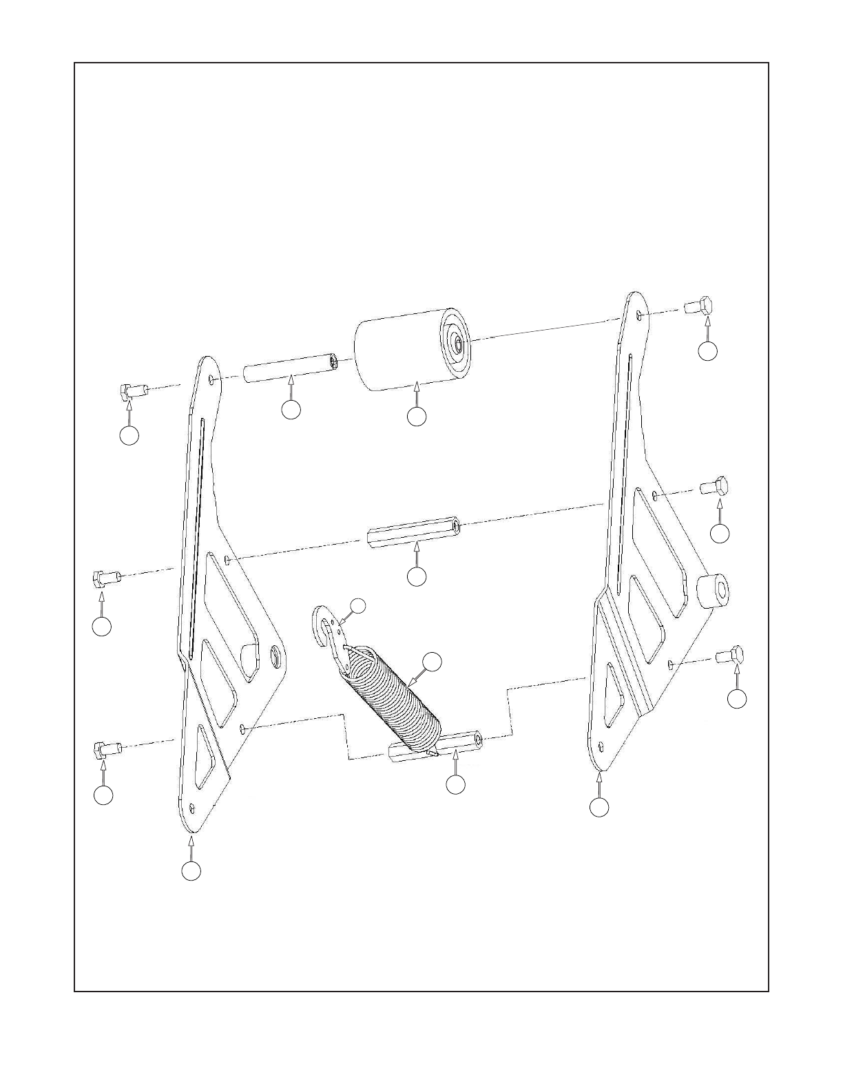
8
6
4
3
7
7
7
7
7
7
1
2
5
9
Figure 10920 – Lower Head
AccuGlide 3 Taping Head - 2"

37
Figure 10920– Lower Head
AccuGlide 3 Taping Head - 2" 2009 February
Ref. No. 3M Part No. Description
10920-1 78-8137-3300-9 Buffi ng Arm – Sub Assembly
10920-2 78-8137-3301-7 Buffi ng Arm – Sub Assembly
10920-3 78-8052-6575-4 Shaft – Roller
10920-4 78-8137-1398-5 Roller - Buffi ng Assembly
10920-5 78-8070-1220-4 Spacer – Spring
10920-6 78-8052-6580-4 Spacer
10920-7 26-1003-5829-5 Screw – Hex Hd, M6 x 12
10920-8 78-8137-3312-4 Spring – Lower (100 fpm)
10920-9 78-8070-1244-4 Holder – Spring
38
THIS PAGE IS BLANK

39

40
