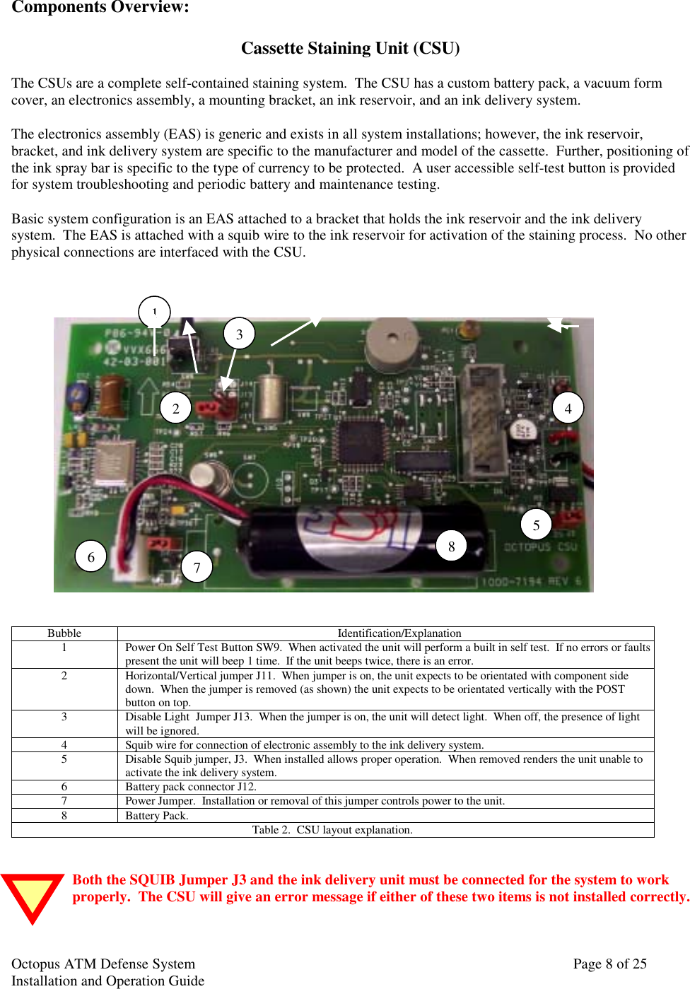
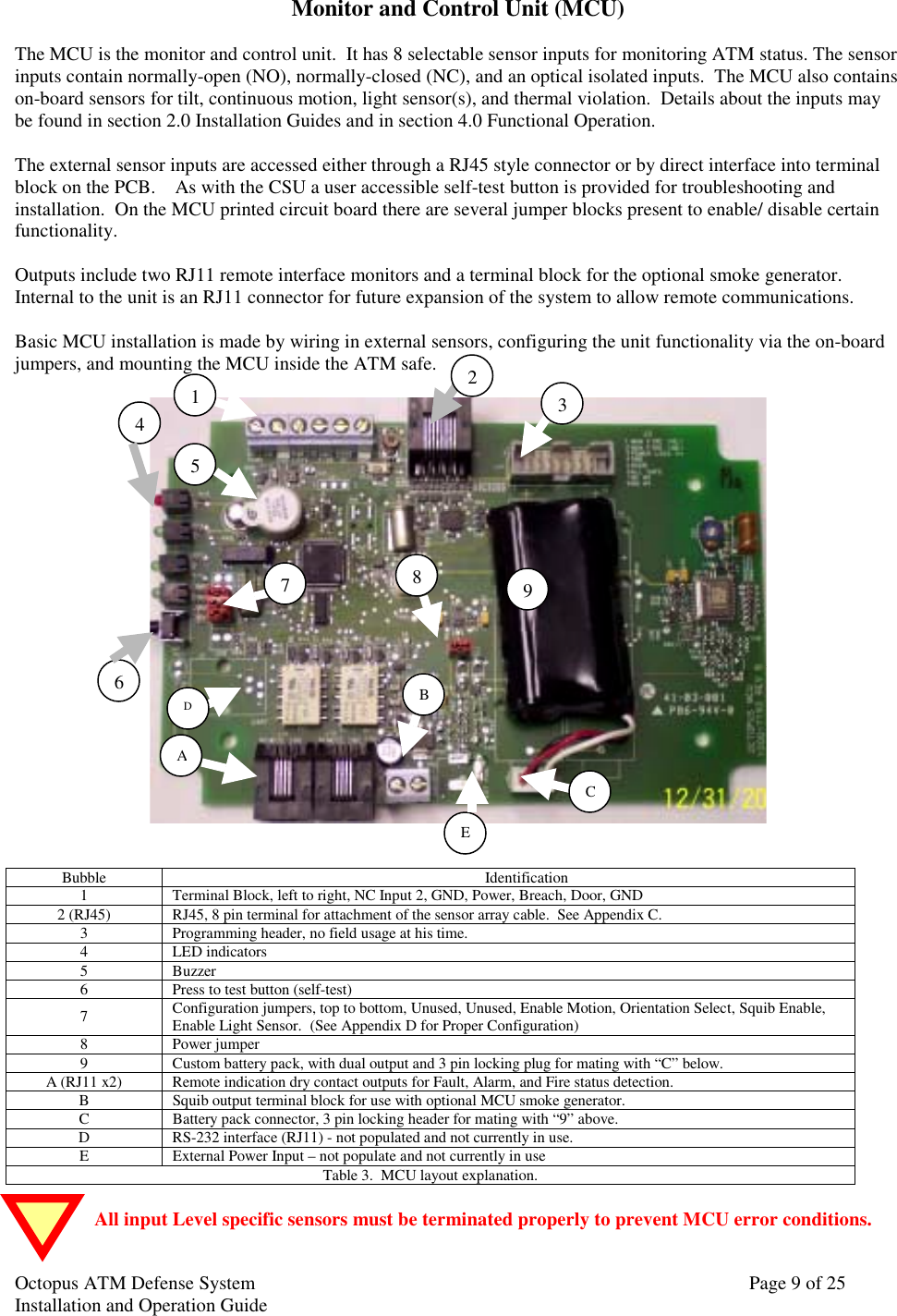
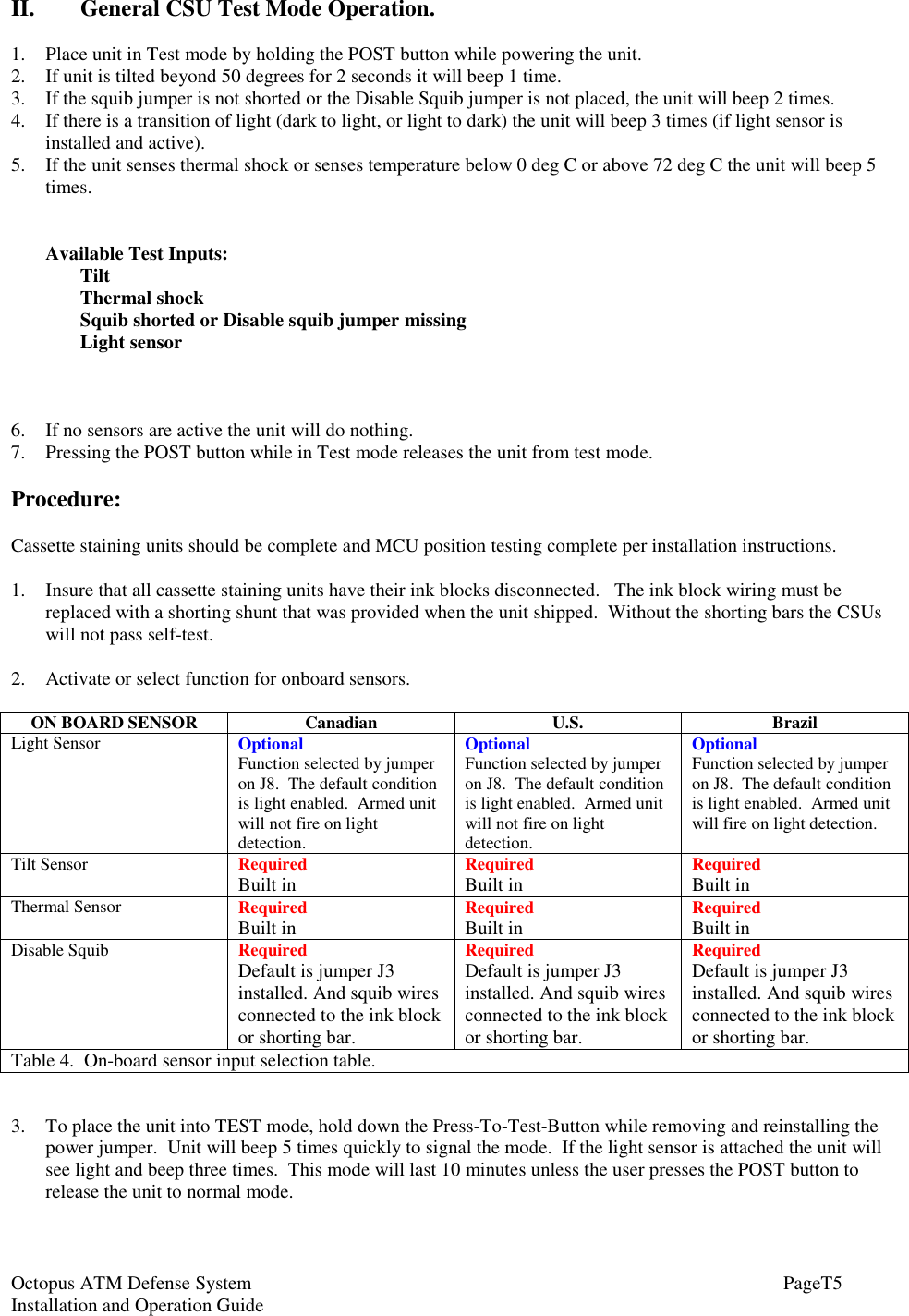
3Si Security Systems 1000-7251 ATM SECURITY SYSTEM User Manual 04 0056 Manual Cover
3Si Security Systems Inc. ATM SECURITY SYSTEM 04 0056 Manual Cover
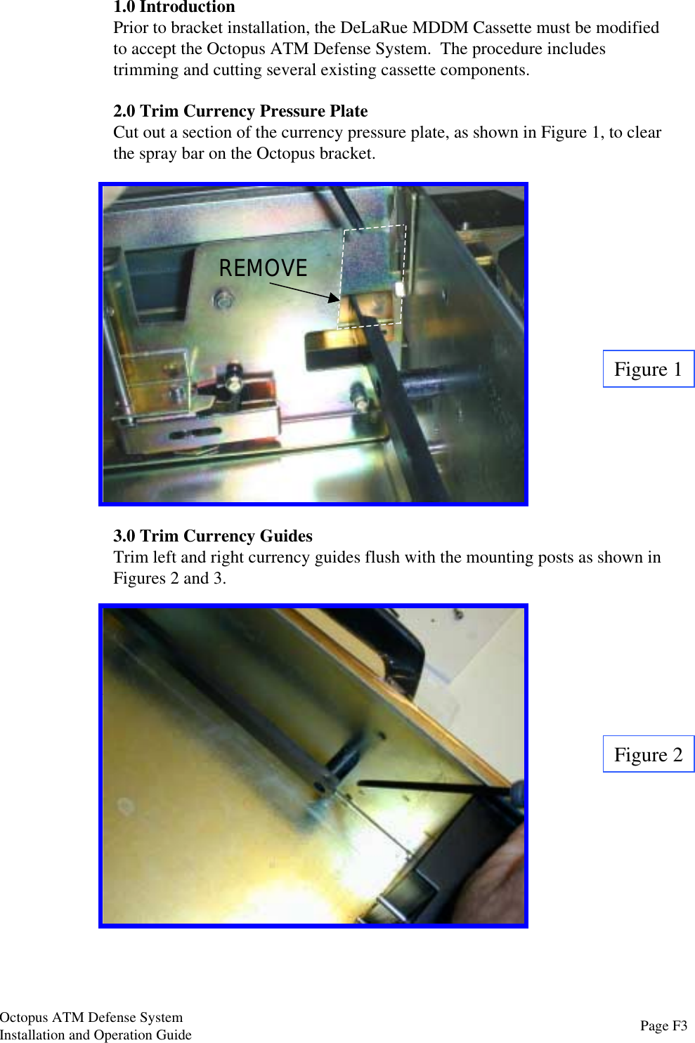
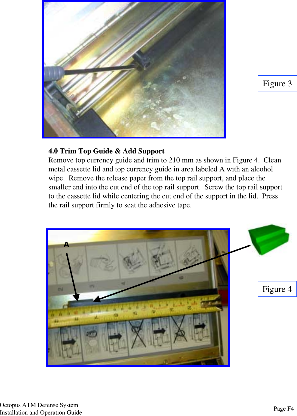
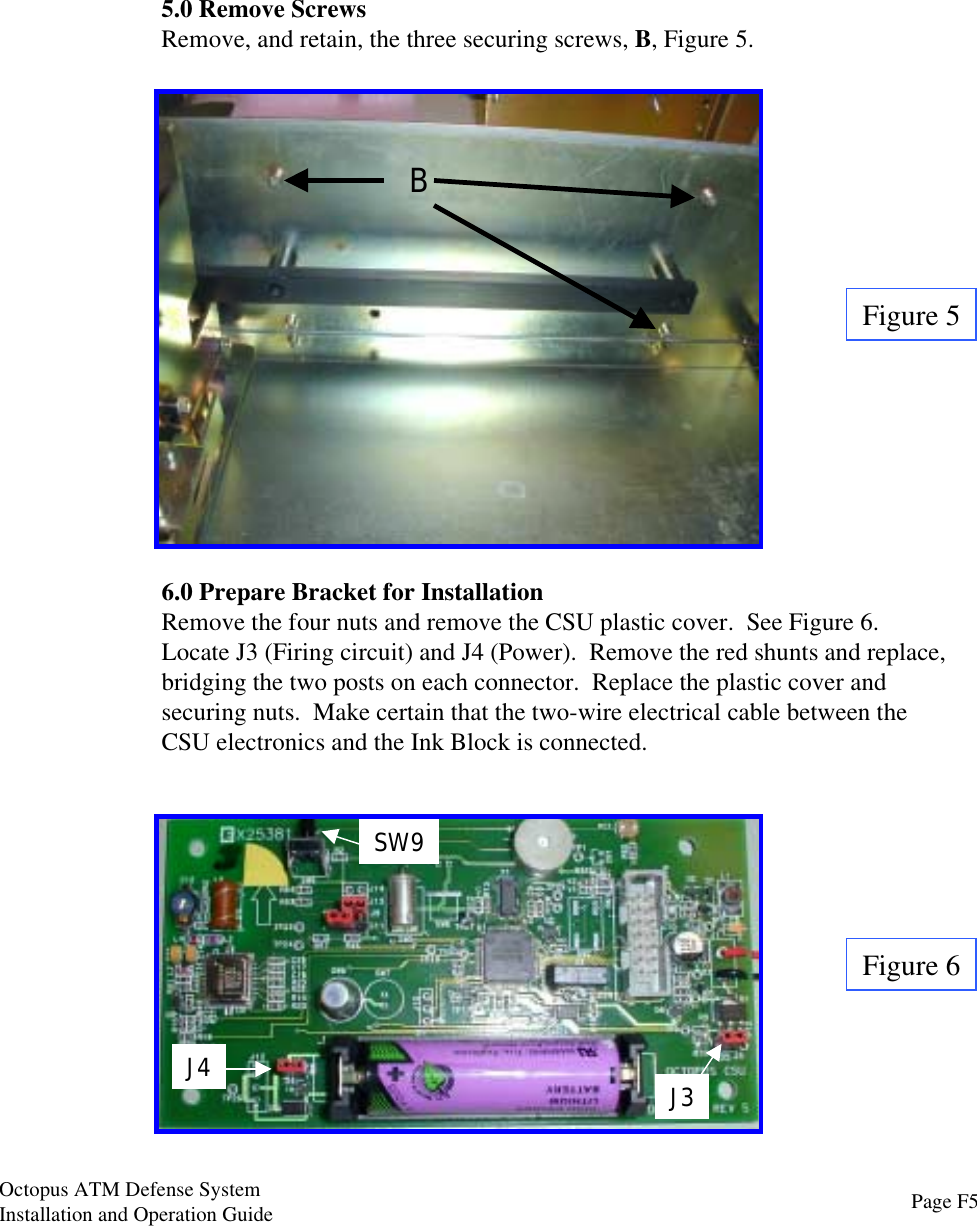
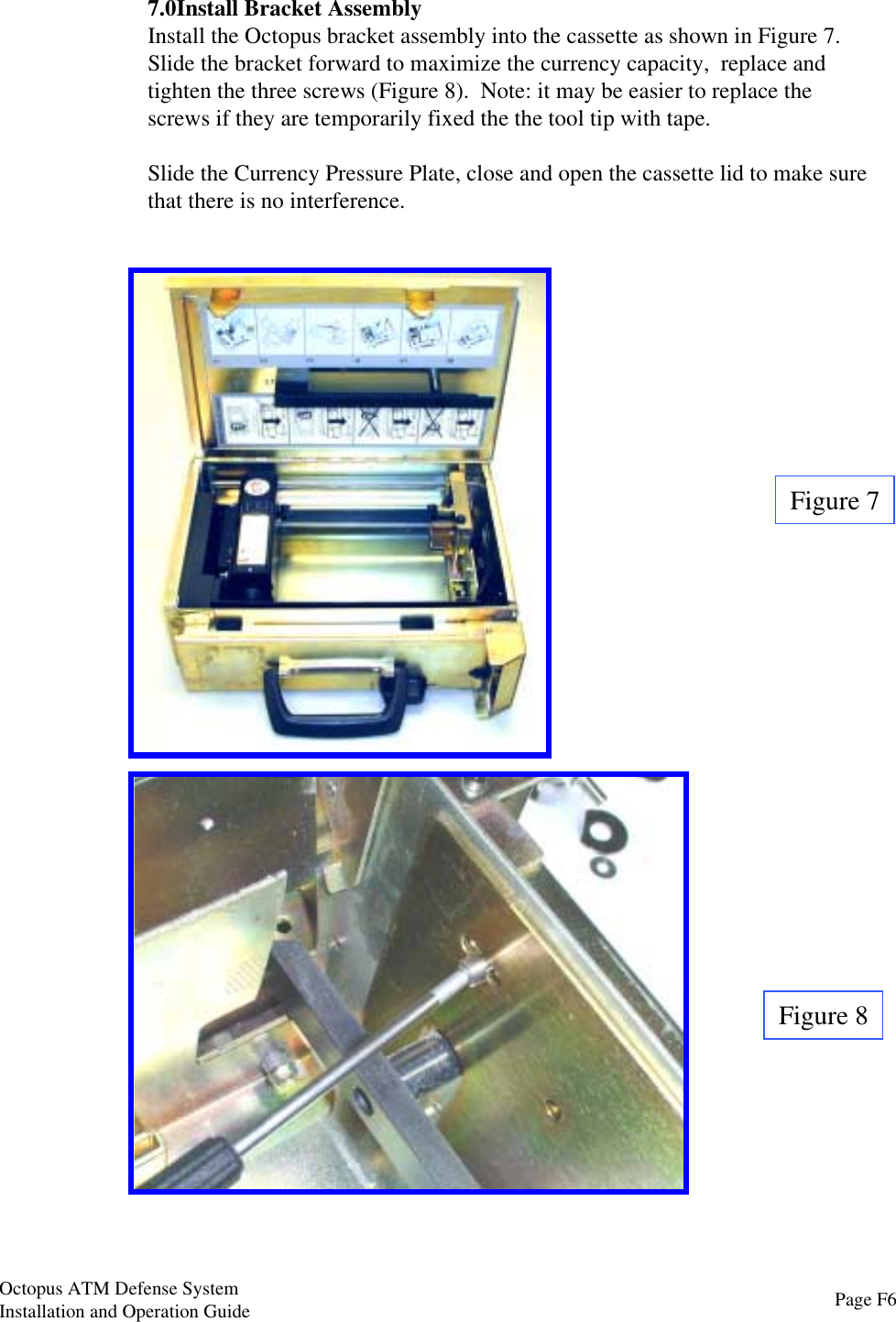
UserManual.wiki
>
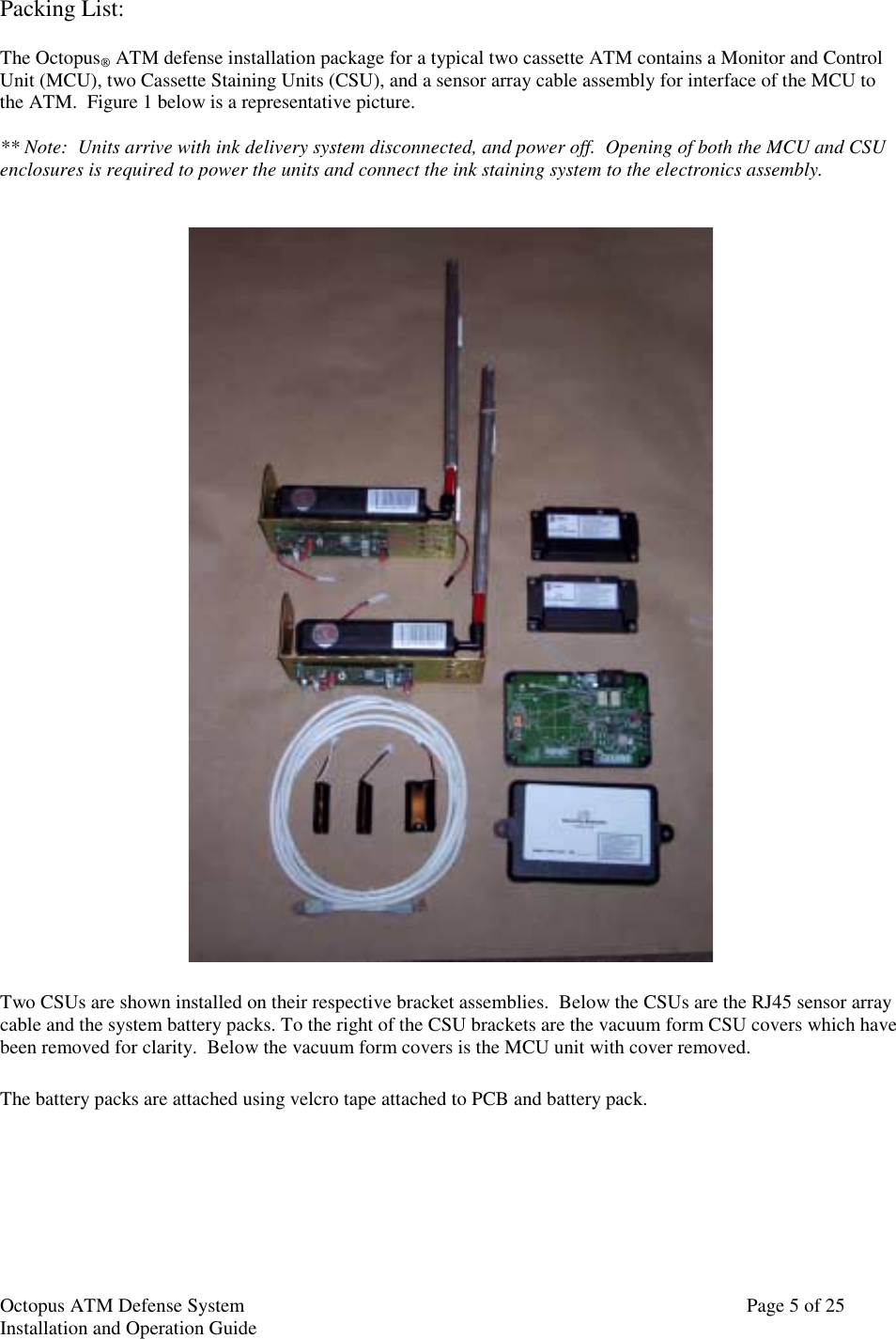
3Si Security Systems
>
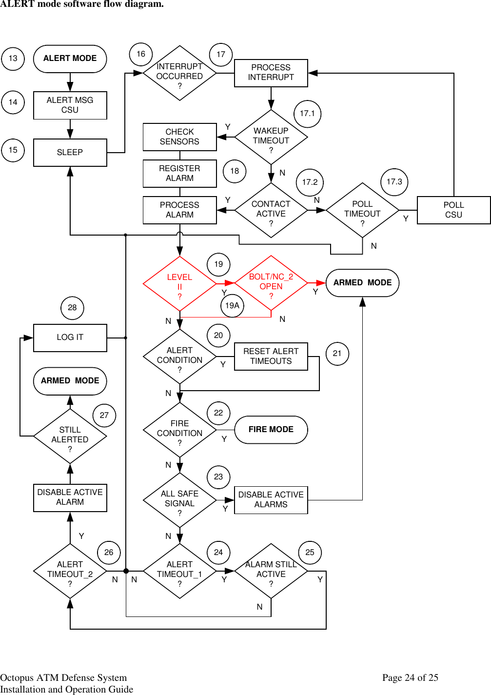
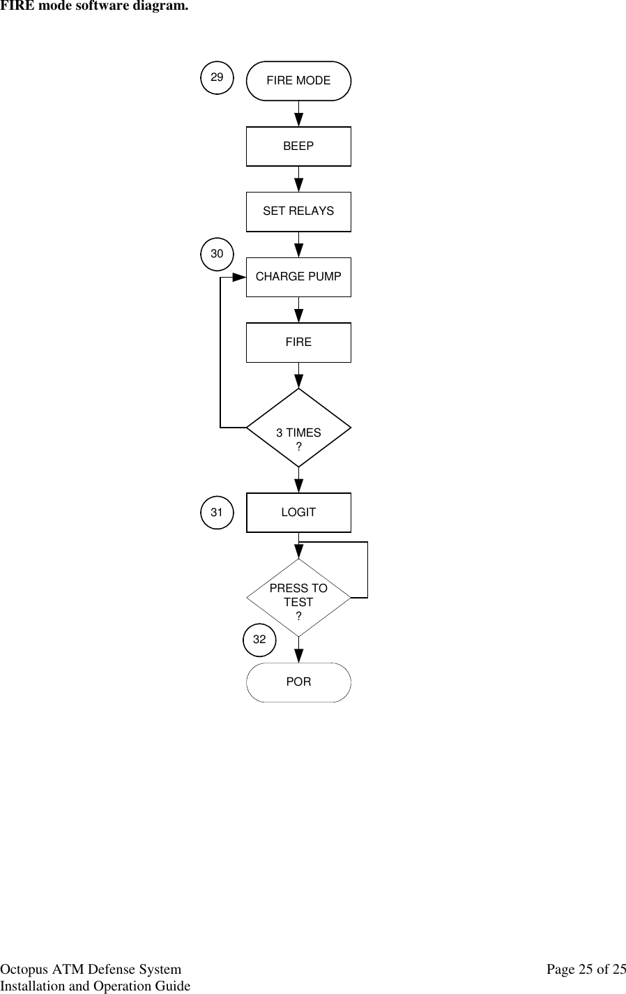
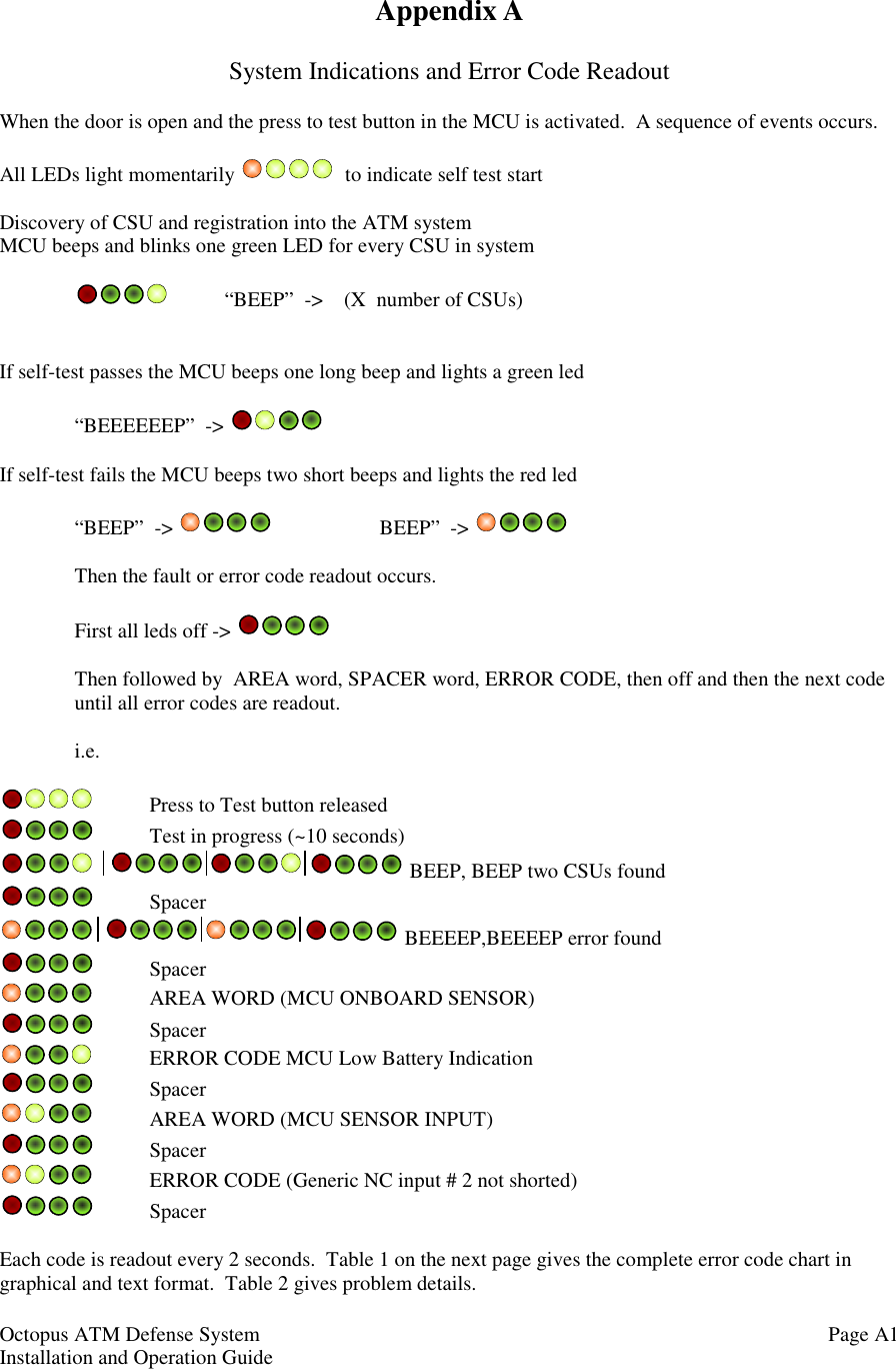
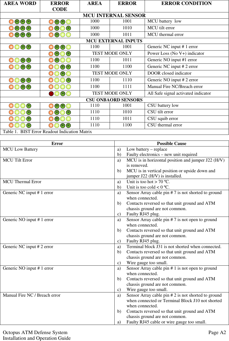
1000 7251 User Manual
USERS MANUAL
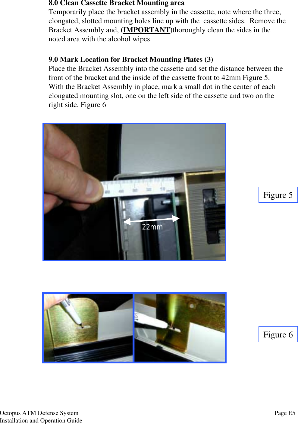
Navigation menu
Upload a User Manual
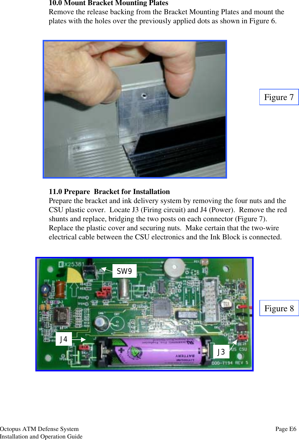
Namespaces
Wiki Guide
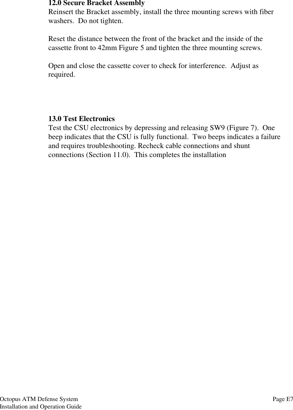
HTML
PDF
Info
Views
User Manual
Discussion / Help
Navigation