3Si Security Systems 1000-7251 ATM SECURITY SYSTEM User Manual 04 0056 Manual Cover
3Si Security Systems Inc. ATM SECURITY SYSTEM 04 0056 Manual Cover
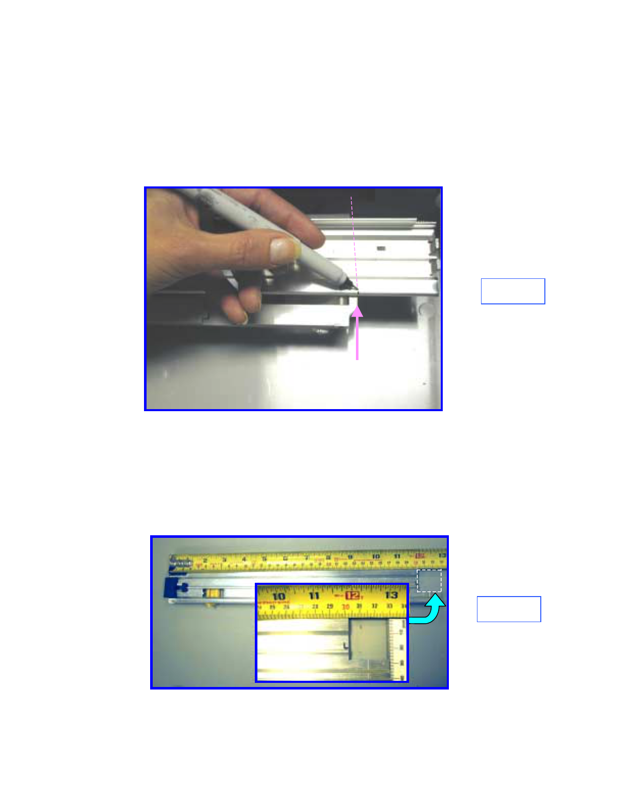
USERS MANUAL

5015 B.U. Bowman Drive Buford, GA 30518 USA Voice: 770-831-8048 Fax: 770-831-8598
Certification Test Report
433.92 MHz Alarm System
FCC ID: Q6K 1000-7251
FCC Rule Part: 15.231
ACS Report Number: 04-0056-15C231
Manufacturer: 3SI Security Systems
Model: MCU
Installation and Operators Guide

486 Thomas Jones Way (800) 523-1430 (V)
Exton, PA 19341 (610)-280-2079 (F)
Overview:
The Octopus ATM Defense System is a wireless system
consisting of an ATM Monitor and Control Unit (MCU) and
Cassette Staining Units (CSU). This system, once installed into
an ATM, becomes a closed wireless protection network within
the ATM.
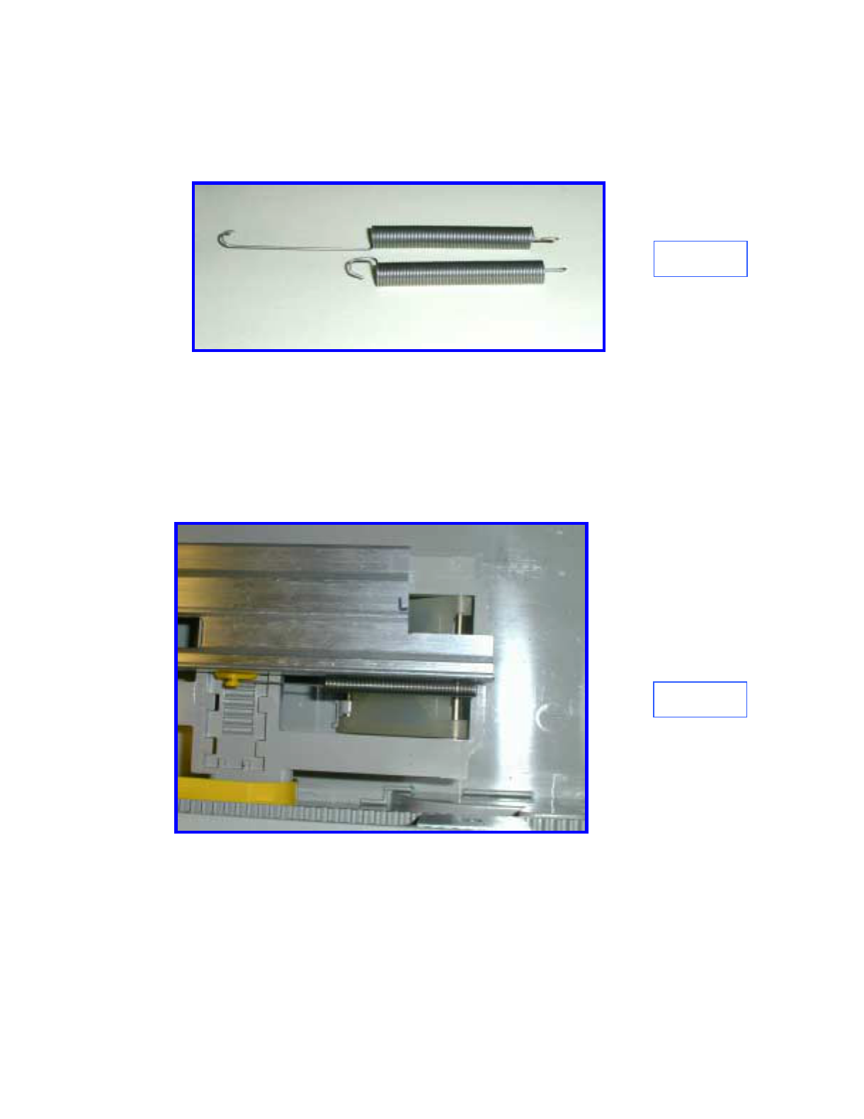
The operational frequency of the system is set to allow worldwide
operation and deployment of the protection system. Currently,
the system is UL, FCC, IC, and CE compliant.
The system is designed for continuous monitoring and protection
of ATM cassette based currency for two years. Both the MCU
and CSU are powered via custom battery packs which allow
installation without requiring interface to external power. The
mechanical dimensions of the product allow the MCU to be
placed almost anywhere within the ATM safe, while the bracket
design of the CSU allows for fast field installation.
Actual Stained Currency ---
Deny the Prize
Features:
• Self-contained battery operated system with life cycle greater than 2 years.
• Continuous wireless communications status monitoring.
• Fast installation time, usually less than 1 hour
• Provides protection against tilt, motion, power failures and breach of the ATM safe.
• Compatible with most leading ATM sensor array packages.
• Requires single wire interface to begin protection
• Uses industry preferred currency staining method.
• Proprietary wireless communications protocol.
• Can provides external remote monitoring signals.
Octopus ATM Defense System
Installation and Operation Guide Page 2 of 25
Table of Contents
Overview: ...................................................................................................................................................................1
Features: .....................................................................................................................................................................1
Table of Contents........................................................................................................................................................2
Product Specification:.................................................................................................................................................6
Components Overview: ..............................................................................................................................................8
Cassette Staining Unit (CSU).....................................................................................................................................8
Monitor and Control Unit (MCU) ..............................................................................................................................9
Installation Instructions: ...........................................................................................................................................10
CSU Installation ..................................................................................................................................................10
MCU Installation .................................................................................................................................................11
Basic Operation:.......................................................................................................................................................13
Detailed Operation:...................................................................................................................................................15
Appendix A: System Indication and Error Code Readout
Appendix B: Optional Components
Appendix C: MCU Sensor Array and RIM Wiring
Appendix D: Configuration Jumper Selection Guide
Appendix E: Installation Instruction Diebold MMD Cassette
Appendix F: Installation Instruction DeLaRue MDDM Cassette
Appendix G: Installation Instruction Perto "A" C-130 Cassette
Appendix H: Installation Instruction DeLaRue NMD Cassette
Appendix I: Installation Instruction NCR Cassette
Appendix J: Mode Jumper Selection (Preliminary Only)
Appendix T: Test Mode
Octopus ATM Defense System
Installation and Operation Guide Page 3 of 25
Copyright 3SI Security Systems, Inc. 2003
All Rights Reserved.
Except as allowed by copyright laws or herein, reproduction, adaptation, or translation without prior written
permission is prohibited. A user of the Octopus ATM Defense System associated with this guide is granted a
license to print hard copies of this guide for internal or company use subject to the restriction not to sell, resell, or
otherwise distribute the hard copies.
Warranty
The information contained in this document is subject to change without notice.
3SI Security Systems makes no warranty of any kind with respect to this information.
3SI SECURITY SYSTEMS SPECIFICALLY DISCLAIMS THE IMPLIED WARRANTY OF
MERCHANTABILITY AND FITNESS FOR A PARTICULAR PURPOSE.
Octopus ATM Defense System
Installation and Operation Guide Page 4 of 25
FCC regulations
NOTE: This equipment has been tested and found to comply with the limits for a Class B digital device, pursuant
to Part 15 of the FCC Rules. These limits are designed to provide reasonable protection against harmful
interference in a residential installation. This equipment generates, uses and can radiate radio frequency energy
and, if not installed and used in accordance with the instructions, may cause harmful interference to radio
communications. However, there is no guarantee that interference will not occur in a particular installation. If this
equipment does cause harmful interference to radio or television reception, which can be determined by turning
the equipment off and on, the user is encouraged to try to correct the interference by one or more of the following
measures:
· Reorient or relocate the receiving antenna.
· Increase the separation between the equipment and receiver.
· Connect the equipment into an outlet on a circuit different
from that to which the receiver is connected.
· Consult the dealer or an experienced radio/TV technician for
help.
All Equipment:
Warning: Changes or modifications to this device not expressly approved by 3SI Security Systems could
void the user’s authority to operate the equipment.
RF Exposure (Intentional Radiators Only)
In accordance with FCC requirements of human exposure to radio frequency fields, the radiating element shall be
installed such that a minimum separation distance of (20cm).
Note: The FCC and IC may require additional information to the user be included in the manual after review of the
application.
Industrie Canada Compliance Statement
This ISM device complies with Canadien ICES-001
Cet appereil ISM est conforme à la norme NMB-001 du Canada.
CE Mark Warning
This is a class B product. IN a domestic environment, this product may cause radio interference, in which the user
may be required to take adequate measures.
Octopus ATM Defense System
Installation and Operation Guide Page 5 of 25
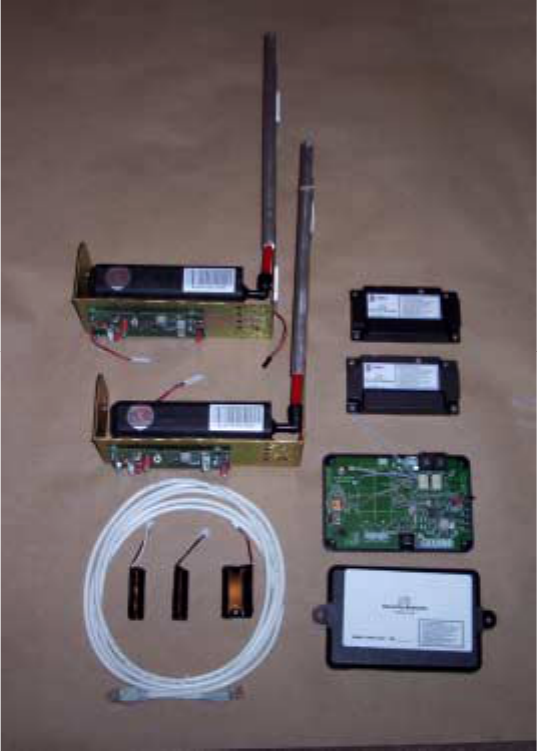
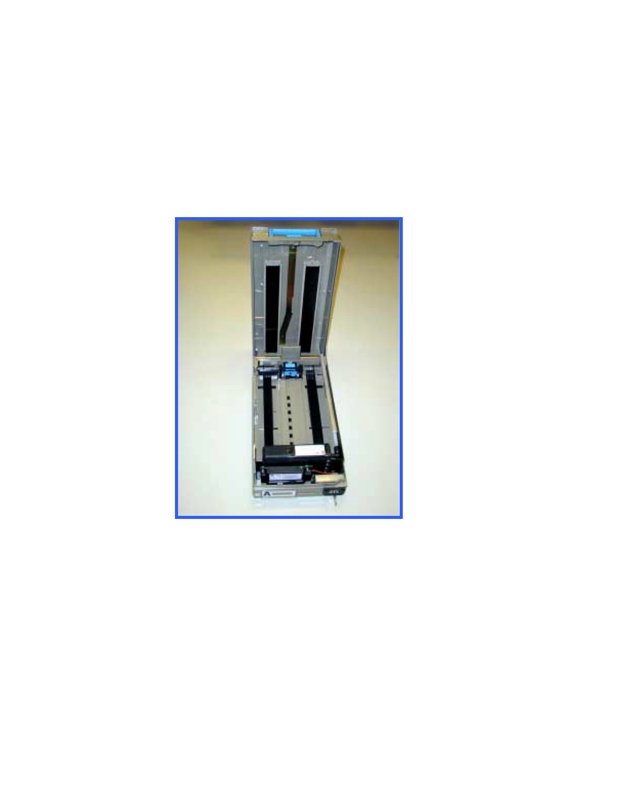
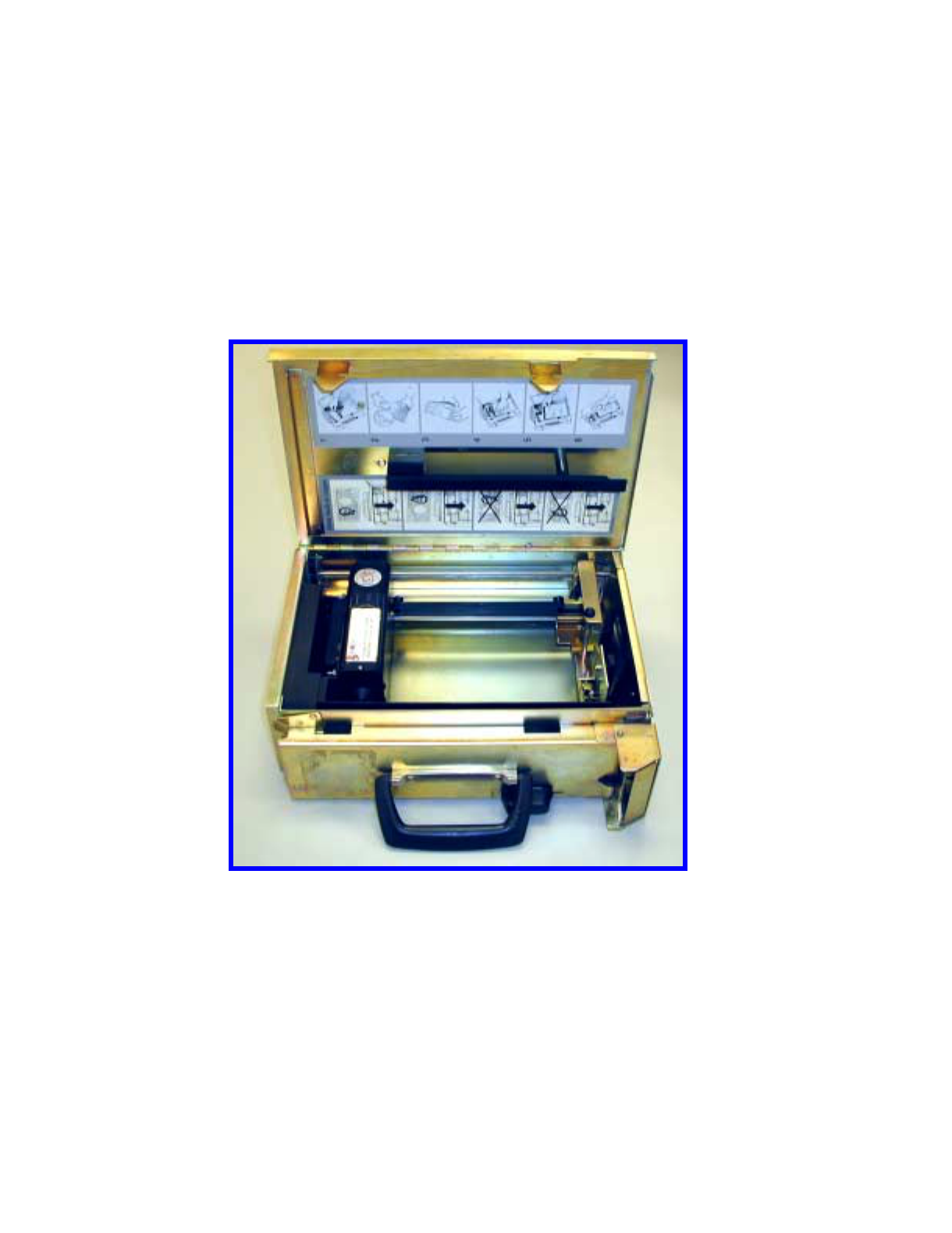
Packing List:
The Octopus ATM defense installation package for a typical two cassette ATM contains a Monitor and Control
Unit (MCU), two Cassette Staining Units (CSU), and a sensor array cable assembly for interface of the MCU to
the ATM. Figure 1 below is a representative picture.
** Note: Units arrive with ink delivery system disconnected, and power off. Opening of both the MCU and CSU
enclosures is required to power the units and connect the ink staining system to the electronics assembly.
Two CSUs are shown installed on their respective bracket assemblies. Below the CSUs are the RJ45 sensor array
cable and the system battery packs. To the right of the CSU brackets are the vacuum form CSU covers which have
been removed for clarity. Below the vacuum form covers is the MCU unit with cover removed.
The battery packs are attached using velcro tape attached to PCB and battery pack.

Octopus ATM Defense System
Installation and Operation Guide Page 6 of 25
Product Specification:
Monitor and Control Unit (MCU)
Description Specification Comments
Size: 3.3 x 5.6x 1.25 “
Operational Frequency: International Acceptance Frequency is not given for
security reasons.
Press-to-test button User accessible allows system
testing during service and
installation.
One RJ45, 8 wire, sensor array
cable
Contains:
Door Contact Interface
Power Loss Interface
All Safe Interface
Manual Fire
1 N/C generic input
2 N/O generic input
1 system ground wire
Door Contact must be used either
through the sensor cable or via
the terminal block in order to
activate the system.
Power Loss Interface is optically
isolated.
Terminal Blocks:
2 system ground inputs
1 Door Contact Interface
1 Manual Fire Interface/Breach
Power Loss Interface
1 N/C generic input
Terminal blocks accept wire from
18-24 AWG.
Manual Fire Interface is generally
used with a breach sensor.
Battery Pack connector
External Power Connector Currently not populated
Inputs:
14 Pin factory programming
header Not for customer use
Three RJ11, 4 wire
2 Remote Indicator connectors
(J14 & J15)
Contains:
Alarm Status Indication
Fault Status Indication
1 RS232 Interface (J2)
An optional remote indicator
assembly will be available to
allow visual and aural indication
of system state to allow
authorized personnel system
status indication.
Remote Indicator connections are
mutually redundant.
Optional siren may be connected
to these connectors.
(Future options - not installed)
Outputs
Squib output For connection to optional smoke
generator.
4 LED indicators See Appendix A for explanation
of operation.
Onboard Sensors Tilt 50° , 2 axis
Motion / Vibration, 2 axis.
Thermal –50 to +150 °C
Light Sensor
Operation using the light sensor
and thermal sensor are optional
on the standard product.

Octopus ATM Defense System
Installation and Operation Guide Page 7 of 25
Battery Pack Custom design dual output Long Life Lithium Technology
for unsurpassed performance.
Onboard jumper options Power jumper, J4
H/V jumper, J22
DM, J24
DS, J3
Configuration jumper J25
Configuration jumper J26
Configuration jumper information
can be found in Appendix D.
Agency compliance UL, FCC, IC, CE
Cassette Staining Unit (CSU)
Size Defined based on manufacturer
and model of the currency
cassette
Supported Currency Cassette: Deibold MMD
Diebold MDDM
NCR narrow-body
NCR wide body
Perto
DeLarue NMD
Wincor-Nixdorf
Press-to-test button User accessible allows system
testing during service and
installation.
Battery Pack Connector
Input
14 Pin factory programming
header
Outputs Two wire Squib output cable
Onboard Sensors
Tilt 50° , 2 axis
Motion / Vibration, 2 axis.
Thermal –50 to +150 °C
Light Sensor
Onboard jumper options
Power jumper, J4
H/V jumper, J11
DS, J3
Configuration jumper J13
Configuration jumper J14
Configuration jumper information
can be found in Appendix D.
Battery Pack Custom design dual output Long Life Lithium Technology
for unsurpassed performance.
Agency Compliance UL, FCC, IC, CE
Table 1. Product Specification
Octopus ATM Defense System
Installation and Operation Guide Page 8 of 25
Components Overview:
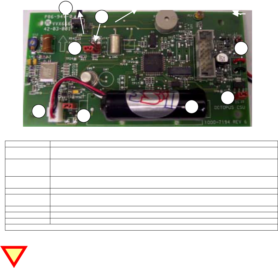
Cassette Staining Unit (CSU)
The CSUs are a complete self-contained staining system. The CSU has a custom battery pack, a vacuum form
cover, an electronics assembly, a mounting bracket, an ink reservoir, and an ink delivery system.
The electronics assembly (EAS) is generic and exists in all system installations; however, the ink reservoir,
bracket, and ink delivery system are specific to the manufacturer and model of the cassette. Further, positioning of
the ink spray bar is specific to the type of currency to be protected. A user accessible self-test button is provided
for system troubleshooting and periodic battery and maintenance testing.
Basic system configuration is an EAS attached to a bracket that holds the ink reservoir and the ink delivery
system. The EAS is attached with a squib wire to the ink reservoir for activation of the staining process. No other
physical connections are interfaced with the CSU.
Bubble Identification/Explanation
1 Power On Self Test Button SW9. When activated the unit will perform a built in self test. If no errors or faults
present the unit will beep 1 time. If the unit beeps twice, there is an error.
2 Horizontal/Vertical jumper J11. When jumper is on, the unit expects to be orientated with component side
down. When the jumper is removed (as shown) the unit expects to be orientated vertically with the POST
button on top.
3 Disable Light Jumper J13. When the jumper is on, the unit will detect light. When off, the presence of light
will be ignored.
4 Squib wire for connection of electronic assembly to the ink delivery system.
5 Disable Squib jumper, J3. When installed allows proper operation. When removed renders the unit unable to
activate the ink delivery system.
6 Battery pack connector J12.
7 Power Jumper. Installation or removal of this jumper controls power to the unit.
8 Battery Pack.
Table 2. CSU layout explanation.
Both the SQUIB Jumper J3 and the ink delivery unit must be connected for the system to work
properly. The CSU will give an error message if either of these two items is not installed correctly.
4
6
5
7
8
1
2
3
Octopus ATM Defense System
Installation and Operation Guide Page 9 of 25
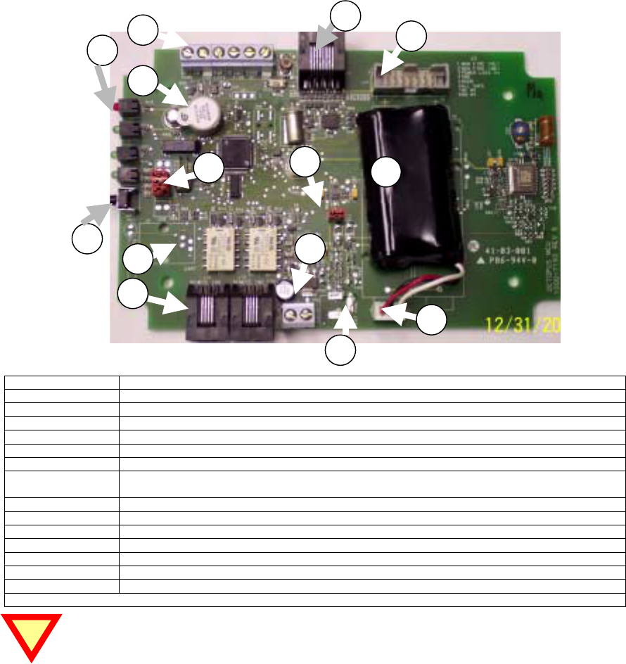
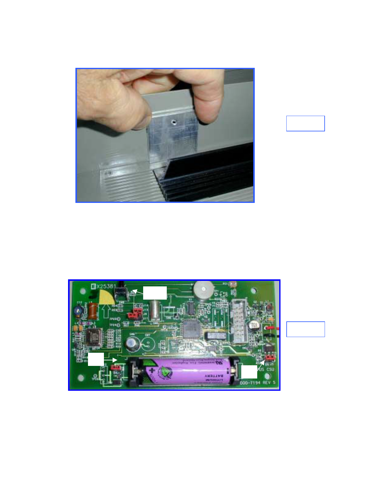
Monitor and Control Unit (MCU)
The MCU is the monitor and control unit. It has 8 selectable sensor inputs for monitoring ATM status. The sensor
inputs contain normally-open (NO), normally-closed (NC), and an optical isolated inputs. The MCU also contains
on-board sensors for tilt, continuous motion, light sensor(s), and thermal violation. Details about the inputs may
be found in section 2.0 Installation Guides and in section 4.0 Functional Operation.
The external sensor inputs are accessed either through a RJ45 style connector or by direct interface into terminal
block on the PCB. As with the CSU a user accessible self-test button is provided for troubleshooting and
installation. On the MCU printed circuit board there are several jumper blocks present to enable/ disable certain
functionality.
Outputs include two RJ11 remote interface monitors and a terminal block for the optional smoke generator.
Internal to the unit is an RJ11 connector for future expansion of the system to allow remote communications.
Basic MCU installation is made by wiring in external sensors, configuring the unit functionality via the on-board
jumpers, and mounting the MCU inside the ATM safe.
Bubble Identification
1 Terminal Block, left to right, NC Input 2, GND, Power, Breach, Door, GND
2 (RJ45) RJ45, 8 pin terminal for attachment of the sensor array cable. See Appendix C.
3 Programming header, no field usage at his time.
4 LED indicators
5 Buzzer
6 Press to test button (self-test)
7Configuration jumpers, top to bottom, Unused, Unused, Enable Motion, Orientation Select, Squib Enable,
Enable Light Sensor. (See Appendix D for Proper Configuration)
8 Power jumper
9 Custom battery pack, with dual output and 3 pin locking plug for mating with “C” below.
A (RJ11 x2) Remote indication dry contact outputs for Fault, Alarm, and Fire status detection.
B Squib output terminal block for use with optional MCU smoke generator.
C Battery pack connector, 3 pin locking header for mating with “9” above.
D RS-232 interface (RJ11) - not populated and not currently in use.
E External Power Input – not populate and not currently in use
Table 3. MCU layout explanation.
All input Level specific sensors must be terminated properly to prevent MCU error conditions.
1
4
5
6
89
A
B
C
E
2
3
7
D

Octopus ATM Defense System
Installation and Operation Guide Page 10 of 25
Installation Instructions:
First the CSUs should be installed into the ATM cassettes, then the MCU can be installed.
Installation of the CSU depends on the manufacturer make and model of the cassette. The instructions for
modification of the supported cassettes are attached in Appendix E through I. Please refer to the table of contents
in order to determine the make and model of the cassette you wish to install.
Insure that all external sensors and switches (DOOR, SMOKE, BREACH, SIREN, etc.) are installed prior to
configuring the MCU. Appendix B contains instruction for these items.
CSU Installation
Upon receipt of the CSU ink delivery system, the vacuum form cover should be removed for initialization and
installation.
1. Verify and install jumpers using Appendix D as required.
The Power jumper (J4), Disable Squib jumper (J3), and either the ink delivery assembly or a squib jumper
attached inside the squib wire connector should be installed.
2. Press the POST button with the unit in the correct orientation for installation into the cassette.
If the self test is good (1 long beep) disconnect the ink delivery system and continue installation.
If there is a fault or error reported use Appendix A to isolate and correct problem.
Squib wires must be shorted or ink block connected for the unit to pass self-test.
3. Follow the bracket installation guides in Appendix E though I depending on the make and manufacturer of the
cassette. • Appendix E -Installation Instruction Diebold MMD
• Appendix F -Installation Instruction DeLaRue MDDM
• Appendix G -Installation Instruction Perto “A” C-130
• Appendix H -Installation Instruction DeLaRue NMD
• Appendix I -Installation Instruction NCR
4. Once the bracket is installed correctly, re-attach the squib connection from the PCB to the ink delivery unit.
5. Press the POST button with the cassette in the correct orientation.
If the self test is good (1 long beep) the installation is complete.
If there is a fault or error reported use Appendix A to isolate and correct problem.
6. Remove ink block from Squib connection and place jumper across CSU wires to safe the system for testing.
CSU INSTALLATION COMPLETE
Test mode may be used to verify unit functionality see Appendix T for instruction.
Octopus ATM Defense System
Installation and Operation Guide Page 11 of 25
Note
MCU Installation
Installation of the MCU is as follows:
1. Open the MCU enclosure by removing the four screws from the cover.
2. Attach power jumper J4. Verify Configuration jumpers using Appendix D.
3. With CSU’s installed into the cassettes with their ink bocks replaced with a jumper on the CSU Squib cable.
Holding it in your hand, place the MCU in the position decided for installation.
4. Press the POST button. Insure proper discovery. Because the MCU will not have all of its input terminated
correctly you should expect error messages; however, ignore them for now. If discovery conditions are good,
proceed to step5. Else move the MCU to a new location and re-initiate the self-test. Repeat until all units are
discovered.
5. Remove power jumper until installation is complete.
6. Place, install, and secure all accessory items. (ie. Bolt indicator switch, door contact switch, siren, breach
sensor, et al.)
7. Run wires to the installation location, with enough slack for later trimming.
8. Determine sensor inputs are to be used. Either the sensor array cable or the onboard terminal block. If using
only the sensor array cable assembly (RJ45 Ethernet cable), skip to step 12.
See picture on page 8.
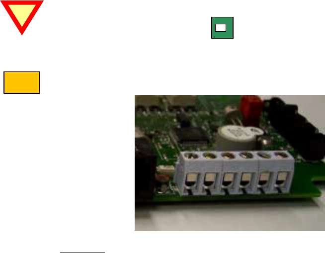
9. Connect all used contacts to the MCU terminal blocks. See picture and note below.
CAUTION: This system uses a common ground. Polarity of the wires is critical to operation. The
ground pins on the terminal block are highlighted with a bold line at back of the
terminal block.
10. Attach wires to the terminal blocks, fastening them by tightening the screw in a clockwise direction.
Loosening the terminal block may be required based on wire guage used and received condition.
NOTE: From right to left the terminal block connections are:
1. Generic NC input # 2
2. GND
3. Power Loss,
4. Manual Fire/Breach
5. ATM Door NC
6. GND
11. Skip to step 16 if the Sensor Array Cable is not used.

Octopus ATM Defense System
Installation and Operation Guide Page 12 of 25
Note
12. Connect all used sensor array wires to the ATM sensor array (or provided sensors). Refer to Appendix C for a
wire color chart of provided cabling.
13. Any unused sensor inputs should be shorted to the ground wire if the are normally closed. If the sensor input
is normally open, caution should be used to insure that they do not make accidental contact to ground.
14. If Test Mode is to be initiated hold down the POST button will re-installing the power jumper J4.
15. If Test Mode is selected got Appendix T for instructions. Else continue below.
16. Fasten case together securely using the 4 screws provided. Insure that no wires or electronic components are
strained or trapped.
17. Using the provided alcohol wipes, insure that the mounting surface is free of debris and oily residue.
18. Remove the protective coating from the velcro strips while they are still attached to the MCU.
19. Place the MCU into place pressing firmly to allow the tape to adhere to the ATM.
20. The cassettes should be installed into the ATM rack.
21. Actuate the MCU’s POST button.
22. Self-test will commence. The first indication will be the flashing of the green LED while the CSU counts the
number of CSUs it found.
23. If all CSUs are reported, then the area of install is acceptable.
24. The second indication will be the self test.
If the self test is good (green led flashed , 1 long beep) proceed to step 26.
If there is a fault or error reported use Appendix A to isolate and correct problem.
Not correcting the fault or error condition may reduce the protection capability of the system.
25. Once all errors and or faults are cleared
26. Clean-up any excess wiring and use cable ties, cable stays, or saddle wires to secure any loose wiring.
27. Close ATM door, listen for CSU beeps, MCU count, and fault indication.
28. If a fault exists go to step 24 repeat until all errors are resolved.
MCU INSTALLATION COMPLETE
29. Remove cassettes, open them, re-attach the ink blocks.
30. Install the cassettes into ATM, replenish as required.
SYSTEM INSTALLATION COMPLETE
Octopus ATM Defense System
Installation and Operation Guide Page 13 of 25
Basic Operation:
A high level functionality follows, but for more detailed operation use the flow diagrams and the discussion on
page 14. Software flow diagrams on pages 15 to 18, shows operation of the Octopus ATM Defense System.
Following the flow diagram each state and its characteristics are discussed in detail.
1. With the CSU installed in the cassettes and the MCU installed in the ATM safe cavity. If power is supplied
to the MCU and CSUs they will be in STANDBY mode. STANDBY is the lowest level of protection,
allowing service and maintenance of the sensors, cassettes, and the ATM itself without fear of activation.
While in this mode, it is possible to detect and correct all sensor errors by using the press-to-test button
located on the MCU.
2. TEST mode may be selected by holding down the POST button while removing and re-installing power to the
unit. See Appendix T for detailed description.
3. Holding the POST button for 2 seconds and then releasing it will perform system self-test. See Appendix A
for Self-Test operation and detailed description.
4. Securing the door will upgrade the system status to ARMED mode. In Level III and Level V operation this is
simply closing the ATM door or actuating the door contact switch. Level II operation requires a bolt indicator
switch to check for authorized door opening. The process steps are discovery (find all units), self-test (find all
errors or faults), report (beep indicate self-test status). This take 10-12 seconds.
5. While armed, the system will wake every second to check for polled alarms, react instantly to interrupt driven
alarms, and periodically poll the CSU to get status and sensor information. Any sensor or input error is
disabled from operation during the STANDBY to ARMED process.
MCU alarms that lead from ARMED to ALERT mode, which are processed every second are:
a) Thermal variation and
b) Motion > 15 seconds.
c) Light detection (in Level V only).
MCU alarms that lead from ARMED to ALERT mode, which are interrupt processed are:
a) Generic NO input # 1,
b) Generic NO input # 2,
c) Generic NC input # 1,
d) Generic NC input # 1 (or Bolt Indicator in Level II), and
e) Power Loss (if power was monitored).
MCU alarms that lead from ARMED to FIRE mode, which are interrupt processed are:
a) Thermal violation (> 72ºC or < 0ºC)
b) Tilt > 2 seconds
c) Manual Fire / Breach.
No CSU alarms lead from ARMED to ALERT or to STANDBY.
6. To disarm an ARMED system follow authorized procedure and open door. In Level III and Level V operation
this is simply opening the ATM door or de-actuating the door contact switch. Level II operation requires a
bolt indicator switch to check for authorized door opening.
7. Activation of any sensor leading to the ALERT mode places the CSUs into ALERT mode. They then activate
their internal sensors (Tilt, Light, Thermal) and listen for instruction from the MCU. The CSUs beep one time
per second to indicate the ALERT mode.
Octopus ATM Defense System
Installation and Operation Guide Page 14 of 25
MCU alarms that lead from ALERT to FIRE mode, which are processed every second are:
a) Thermal violation,
b) Motion > 60 seconds.
c) Light detection (in Level V only).
MCU alarms that leads from ALERT to ALERT mode, which are interrupt processed are:
a) Generic NO input # 1,
b) Generic NO input # 2,
c) Generic NC input # 1,
d) Generic NC input # 1 (or Bolt Indicator in Level II), and
e) Power Loss (if power was monitored).
MCU alarms that leads from ALERT to FIRE mode, which are interrupt processed are:
a) Thermal violation (> 72ºC or < 0ºC)
b) Tilt > 2 seconds
c) Manual Fire / Breach.
CSU alarms that lead from ALERT to FIRE (for a particular CSU) are:
a) Thermal violation (> 72ºC or < 0ºC)
b) Tilt > 2 seconds
Additionally in the Level V Octopus
c) Light Detection
8. The All Safe signal can be used to reset an ALERT system to the ARMED mode. All Safe will ignore any
alarms that may be active in the system.
9. ALERT mode last 60 minutes from the last ALERT event. After 60 minutes if the condition that caused the
event is still asserted, ALERT will continue for 30 minutes longer. If the condition is still asserted it will be
ignored and the system will reset to ARMED mode.
10. Activation of any sensor or condition leading to the FIRE mode will stain the currency. During activation of
the ink staining system, the CSU beep a solid 10 second tone. The MCU also beeps a short tone and sets the
fault and alarm relays while firing its own optional squib.
Level II and Level III functionality will not stain the money if the CSU detects light.
11. After firing the MCU and CSU exchange status information and store this information in an NVRAM log.
The MCU then waits for the POST button to be pressed to reset the system.
12. END BASIC OPERATION

Octopus ATM Defense System
Installation and Operation Guide Page 15 of 25
*
1
2
2A
3
3.1
Detailed Operation:
Software flow diagrams on pages 22 to 25, shows operation of the Octopus ATM Defense System. Following the
flow diagram each state and its characteristics are discussed in detail.
The numbered bubbles ( ) are directly correlated between the flow diagram and the discussion which
follows.
POR
Upon application of power, battery installed and Jumper J4 shorted. The unit will initialize all ports and sensors.
It will the check for the presence of the POST button activation signal.
TEST MODE
Placing the unit in TEST mode:
If the POST button is held down while power is applied (POR) the unit will beep 5 times and go immediately to
test mode. See Appendix T for operation and detailed description of TEST mode operation.
If the POST is not active the unit will go to STANDBY mode.
STANDBY MODE
STANDBY is the lowest level of protection, allowing service and maintenance of the sensors, cassettes, and the
ATM itself without fear of activation. While in this mode, it is possible to detect and correct all sensor errors by
using the press-to-test button located on the MCU.
The Octopus system is automatically placed in this mode, if no alarm is active, by authorized door opening. This
state will remain until either the press-to-test button is pushed, or the door contact switch changes to a normally
closed state.
Arming the system:
For Octopus Level III (US) and Level V (Brazil), closing the door is the action which upgrades the system from
STANDBY mode to ARMED mode. Octopus Level II (Canadian) requires a bolt indicator switch connected to
Generic NC input # 2 before arming the system see 2A..
Arming Octopus Level II (Canadian)
Octopus Level II requires two signals be present, the ATM door contact closed and a Bolt Indicator contact closed
when the bolt is closed to be present before arming the system.
System Self-Test:
While the system is in STANDBY mode it is possible to perform a system test by pressing and holding the POST
button for 2 seconds. The following events will occur:
a) Discovery
A proprietary method for determining how many CSUs are in the system and assigning them
communications channels
b) Beep Count
An indication by the MCU of the number of CSUs in this ATM protection system. This is
accomplished by beeping the MCU buzzer a short beep for each CSU found, while blinking a
green LED. I beep and 1 blink for each CSU.

Octopus ATM Defense System
Installation and Operation Guide Page 16 of 25
3.2
c) CSU self-test
The MCU will cause the CSU to self-test all sensors and inputs. After completion if no errors
are found the CSU will beep once to indicate no faults. If an error exists the CSU will beep 2
times to indicate a fault condition. Further it will report this error to the MCU for BIST code
readout.
d) MCU self-test
The MCU will do an internal self test to determine if errors or faults exist.
e) Fault/error indication
If no errors or fault conditions are found the MCU will beep 1 time and flash the green LED 1
time to indicate good self-test.
If there are any faults or errors which cause BIST errors in the systems both CSU and MCU the
MCU will beep two times and flash the red led 2 times to indicate self-test failure.
BIST error readout:
If during a STANDBY mode self-test a failure occurs which has a BIST error associated with it, each
error will be readout individually using the LEDs to display the errors. The errors will be displayed in
one second intervals until all errors have been shown. See Table 4 below which shoes which errors cause
BIST codes for each Level of the Octopus ATM Defense System. Appendix A should be referenced to
decode and troubleshoot any BIST error code.
Possible BIST error
source Level II (Canadian) Level III (US) Level V (Brazil)
ATM_Door open or
closed
All Safe Signal open or
closed
Power Loss open
MCU motion detection
MCU light detection
CSU light detection
NO BIST ERROR
Generic NC input # 2
closed & ATM Door open BIST Error
ATM Door closed &
Generic NC input # 2
open BIST Error NO BIST Error
Generic NO input # 2
closed
Generic NO input # 2
closed
Generic NC input # 1
open
Power Loss detection
NO BIST Error BIST Error
Generic NC input # 2
open
MCU battery low error
MCU tilt error
MCU thermal error
CSU battery low error
CSU tilt error
CSU thermal error
CSU squib disconnected
or disabled
BIST Error
Table 4. Possible BIST error v/s Octopus Level

Octopus ATM Defense System
Installation and Operation Guide Page 17 of 25
4
5
6
7
8
8.1
ARMED mode operation:
Once a unit enters ARMED mode it is ready to protect the currency inside the ATM cassettes. The beginning of
ARMED mode is very much like the POST operation while in (door open) STANDBY mode. However, now that
the door is secure no BIST readout will occur.
Pre-arm checking of the system.
1) Discovery
A proprietary method for determining how many CSUs are in the system and assigning them
communications channels
2) Beep Count
An indication by the MCU of the number of CSUs in this ATM protection system. This is accomplished
by beeping the MCU buzzer a short beep for each CSU found, while blinking a green LED. I beep and 1
blink for each CSU.
3) CSU self-test
The MCU will cause the CSU to self-test all sensors and inputs. After completion if no errors are found the
CSU will beep once to indicate no faults. If an error exists the CSU will beep 2 times to indicate a fault
condition. Further it will report this error to the MCU for BIST code readout.
4) MCU self-test
The MCU will do an internal self test to determine if errors or faults exist.
Fault/error indication:
If no errors or fault conditions are found the MCU will beep 1 time and flash the green LED 1 time to indicate
good self-test.
If there are any faults or errors which cause BIST errors in the systems both CSU and MCU the MCU will beep
two times and flash the red led 2 times to indicate self-test failure. All active sensors are disabled and not used for
protection of the system.
Sleep / power conservation.
99.84 % of the time the MCU in the ARMED state will be sleep state. It will wake every second to check for
polled sensors (thermal and motion), upon any interrupt capable sensor, or when poll timeout occurs.
Wakeup Event or interrupt:
The system will wake every second to check for polled sensors (thermal and motion), upon any interrupt capable
sensor, or when poll timeout occurs. The CSU listens to determine if a polled communications is pending.
Wakeup Timeout /Check Alarms
=> Every 1 second, the MCU wakes up to check the alarms and sensors.
Regardless of whether the sensor are active all inputs are checked. Then after debounce processing
the alarms are registered as real events. The debounce registration process protects against short
duration glitches and EMI fields.

Octopus ATM Defense System
Installation and Operation Guide Page 18 of 25
8.2
9
10
11
12
8.3
Wakeup Contact Change
Every time a interrupt occurs it is debounce processed and immediately compared for action
based on the software protocol.
Wakeup Polling Timeout
This is a periodic time which causes a interrogation of the CSU status and exchanges information of
state condition between the CSU and MCU.
Alarm verification:
When an alarm event occurs it is said to be “triggered”, this immediately causes the system to verify the validity of
the event by de-bouncing the input. After it is debounced, if the alarm still exists it is verified. Then it is
compared to the logic process to allow determination of action.
Disarming the armed system:
In Level III (US) and Level V (Brazil) the act or disarming an ARMED system is by having the authority to open
the door.
Level II operation requires a bolt indicator switch to check for authorized door opening. Both the Bolt and the
Door must open, in that order. This protects against ATM vandals who remove the ATM door without actuating
the bolt mechanism (unauthorized opening).
Processing ALERT events
The following events can cause an ARMED system to goto ALERT mode, if the sensors are connected and
operational:
a) Generic NC input # 1 open
b) Generic NO input # 1 closed
c) Generic NO input # 1 closed
d) Power Loss
e) Motion > 15 seconds, and
f) Thermal Rise (>30 ºC in two minutes).
In Level III (US) and Level V (Brazil)
g) Generic NC input # 2 open
In Level V (Brazil)
h) Light detection transition from dark to light.
Processing FIRE events
The following events can cause an ARMED system to go to FIRE mode, if the sensors are connected and
operational:
a) Manual Fire/ Breach open
b) Tilt > 2 seconds
In Level II (Canadian)
c) Door opening without bolt (Generic NC input # 2) opening.
If no alarms upgrade the system to ALERT or FIRE mode the unit returns to sleep.

Octopus ATM Defense System
Installation and Operation Guide Page 19 of 25
13
14
15
16
18
19
17.1
17.2
17.3
ALERT mode operation:
ALERT mode is the only mode in which the CSUs can protect themselves. The CSUs are protected againt
thermal, light detection and tilt. This will prevent removal of the CSU from the ATM rack without activation.
Sending ALERT messages to CSU.
The first job of the MCU when going to alert is to notify the CSUs within the ATM system of the event. Including
the reason for the event.
Sleeping.
As with ARMED mode the majority of the ALERT time is spent in a sleep state (~ 98.72%). It will wake every
second to check for polled sensors (thermal and motion), upon any interrupt capable sensor, or when poll timeout
occurs.
Wakeup event or interrupt.
The system will wake every second to check for polled sensors (thermal and motion), upon any interrupt capable
sensor, or when poll timeout occurs. The CSU listens to determine if a polled communications is pending.
Wakeup Timeout /Check Alarms
=> Every 1 second, the MCU wakes up to check the alarms and sensors.
Regardless of whether the sensor are active all inputs are checked. Then after debounce processing
the alarms are registered as real events. The debounce registration process protects against short
duration glitches and EMI fields.
Wakeup Contact Change
Every time a interrupt occurs it is debounce processed and immediately compared for action
based on the software protocol.
Wakeup Polling Timeout
This is a periodic time which causes a interrogation of the CSU status and exchanges information of
state condition between the CSU and MCU.
Alarm verification:
When an alarm event occurs it is said to be “triggered”, this immediately causes the system to verify the validity of
the event by de-bouncing the input. After it is debounced, if the alarm still exists it is verified. Then it is
compared to the logic process to allow determination of action.
Disarming the armed system:
Level II operation requires a bolt indicator switch to check for authorized door opening. Both the Bolt and the
Door must open, in that order. This protects against ATM vandals who remove the ATM door without actuating
the bolt mechanism (unauthorized opening).
Processing ALERT events
The following events can cause an ALERT system to stay in ALERT mode, if the sensors are connected and
operational:
20

Octopus ATM Defense System
Installation and Operation Guide Page 20 of 25
25
a) Generic NC input # 1 open
b) Generic NO input # 1 closed
c) Generic NO input # 1 closed
d) Power Loss
e) Motion > 15 seconds, and
f) Thermal Rise (>30 ºC in two minutes).
Resetting all ALARM counters.
There a two main timers used in ALERT mode:
TIMEOUT_1 = 60 minute alert condition. All alert events cause the unit to stay in ALERT
mode for 60 minutes from the last ALERT event. At the end of TIMEOUT 1
the status of the ALERT event is rechecked see 24.
TIMEOUT_2 = 30 minute secondary timer. If the last ALARM to cause alert is still asserted
After the end of TIMEOUT_1 it is held in ALERT mode for an additional
30 minute interval see 26.
Processing FIRE events
The following events can cause an ALERT system to go to FIRE mode, if the sensors are connected and
operational:
a) Door opening
b) Manual Fire/ Breach open
c) Tilt > 2 seconds
In Level II (Canadian)
d) Door opening without bolt (Generic NC input # 2) opening.
Disarming an ALERT system.
Provision has been made the an ALL_SAFE signal, to denote authorized access, is incorporated in the system for
those who wish to deactivate the system and gain access to the safe without causing a fireable condition. This
signal is a NC to NO transition. The system is not deactivated on ALL_SAFE operation but it is placed in
ARMED mode and all alarm conditions and timers are reset to allow opening the door to DISARM the system.
In Level II (Canadian) operation the bolt indicator acts to disarm the system.
Checking for last ALERT condition timeout.
As stated in 21 above, an ALERT system will remain in ALERT mode for a minimum of 60 minutes unless the
ALL_SAFE signal is applied.
Verifying that the last ALERT event is still active after 60 minutes.
If the event is still active it will be disabled; however, the system will continue in the ALERT state for an
additional 30 minutes.
Checking for last still active ALERT condition timeout.
As stated in 21 above, an ALERT system will remain in ALERT mode for a minimum of 30 minutes after the
initaial 60 minute count if the contact which caused the last alert is still active.
21
22
23
24
26

Octopus ATM Defense System
Installation and Operation Guide Page 21 of 25
Final ALERT event check.
After 90 minutes of ALERT mode, the system looks to make sure that all ALERT events that are inactive have
been held for 60 minutes minimum, and any active ALERT event has been in affect for 90 minutes. Any active
ALERT event at this time is disabled, the system will return to the ARMED mode until either a STANDBY event
or another ALERT event occurs.
Logging all events.
All alert conditions are logged to a LIFO register in non-volatile random access memory (NVRAM). The purpose
of the log file is to generate the trail of events leading to activation. Currently the only way to retrieve the
NVRAM information is to export the unit back to the factory for investigation. Using specialized software a
report can be generated of the events.
Keep in mind that the events are only those which cause the unit to go to ALERT and FIRE mode, no real time
clock is installed to allow event tracking to a specific time.
FIRE mode operation
Fire mode in the last stage of an ATM attack. Any unit elevated to this level will stain the currency. This state is
irrevocable. The unit sends a message to the CSU to degrade the currency, then the MCU warns of the event be
beeping. Further any optional device atached to the MCU (siren or smoke) is also activated.
Setting the output relays.
Two outputs on RJ11 jacks are provided for customer and internal monitoring of system status. The are called
FAULT and ALERT. When an error condition or fault in the system occurs, the FAULT relay is closed. When an
ALERT event occurs, the ALERT RELAY is closed. When a fire EVENT is processed both the FAULT and
ALERT relays are closed. The reasoning is that if both a system fault and an ALERT condition exist, the ATM
need service or police intervention. And, when the system fires the system will require maintenace.
FIRE event.
The Octopus ATM Defense system communicates wirelessly to the CSUs to cause staining. Further, any optional
device attached to the MCU is activated. A charge pump is used to generate sufficient energy density to fire the
pyrotechnic actuators. This pump take > 2 seconds to accomplish this task. Further the charge is pumped and
applied a minimum of 3 times to the pyrotechnic device to insure proper activation.
Logging all events.
All fire conditions are logged to a LIFO register in non-volatile random access memory (NVRAM). The purpose
of the log file is to generate the trail of events leading to activation. Currently the only way to retrieve the
NVRAM information is to export the unit back to the factory for investigation. Using specialized software a
report can be generated of the events.
Keep in mind that the events are only those which cause the unit to go to ALERT and FIRE mode, no real time
clock is installed to allow event tracking to a specific time.
After system activation:
After system activation all units wait for their POST buttons to be pressed before continuing operation. This is the
safe condition to prevent degradation of the NVRAM data with after FIRE event tasks.
End of Detailed Operation.
27
28
29
30
31
32
Octopus ATM Defense System
Installation and Operation Guide Page 22 of 25
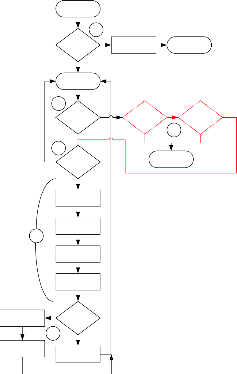
POR and STANDBY mode flow chart
PRESS TO
TEST
?
POR
PRESS TO
TEST
?
DISCOVERY
SELFTEST
CSU
SELFTEST
MCU
BEEP COUNT
DOOR
OPEN
?
BOLT
CLOSED
?
FAULT
EXIST
?
1 BEEP
MCU
2 BEEP
MCU
ERROR
READOUT
TEST MODE
See APPENDIX T
Y
Y
Y
LEVEL
II
?
ARMED MODE
Y
Y
5 BEEPS
STANDBY MODE
2A
2
3.1
3
3.2
1
N
N
N
N
N
Octopus ATM Defense System
Installation and Operation Guide Page 23 of 25
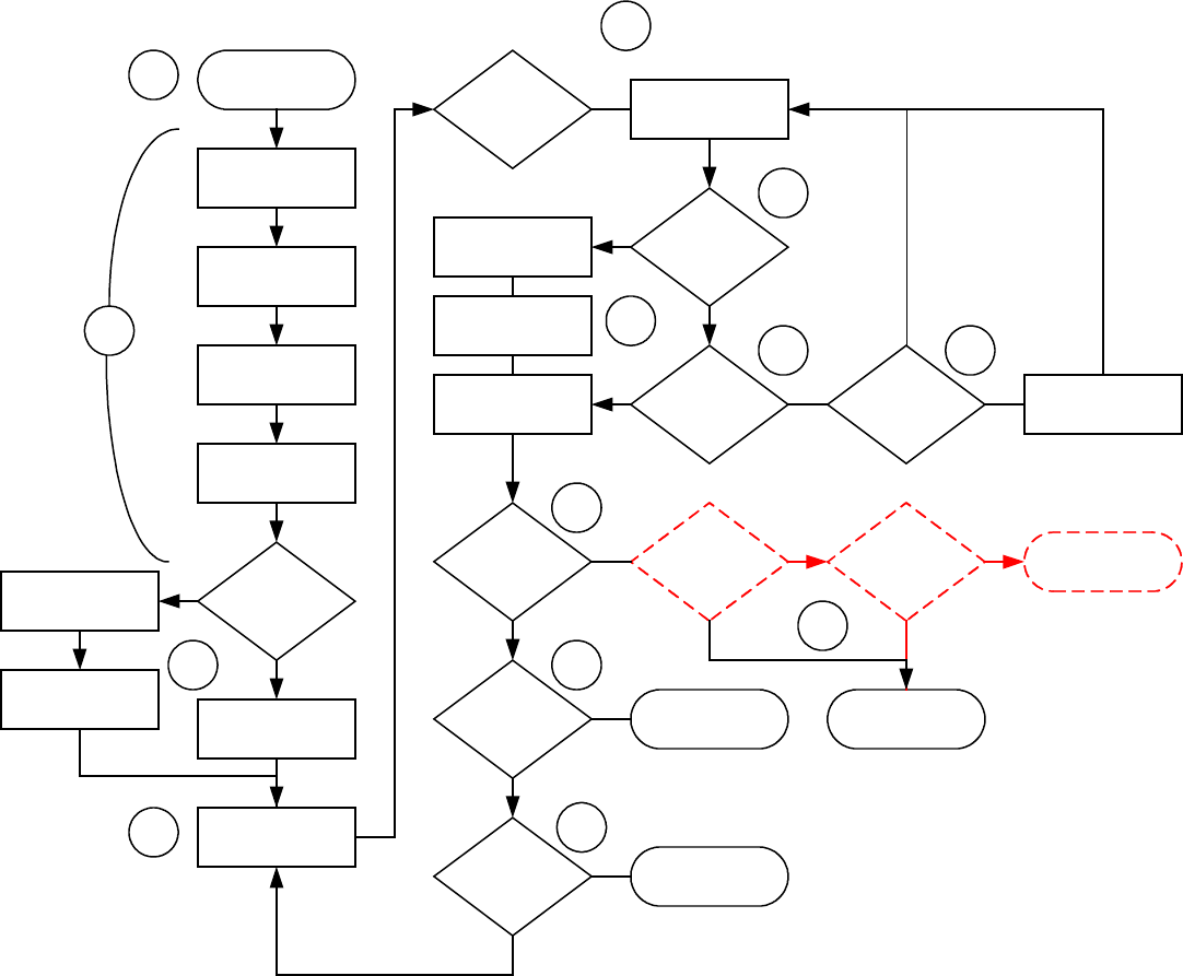
ALERT mode software flow diagram
ARMED
DISCOVERY
SELFTEST
CSU
SELFTEST
MCU
BEEP COUNT
DOOR
CLOSED
?
BOLT/NC_2
CLOSED
?
FAULT
EXIST
?
1 BEEP
MCU
2 BEEP
MCU
Y
N
LEVEL
II
?
STANDBY MODE
YY FIRE MODE
YN
ALERT
CONDITION
?
FIRE
CONDITION
?
POLL
TIMEOUT
?
ALERT MODE
FIRE MODE
POLL
CSU
SLEEP
DISABLE ACTIVE
INPUTS
WAKEUP
OCCURRED
?
WAKEUP
TIMEOUT
?
CONTACT
CHANGE
?
PROCESS
INTERRUPT
REGISTER
ALARM
PROCESS
ALARM
CHECK
SENSORS
4
5
6
7
8
9
8.1
8.2 8.3
10
11
12
10A
Y
N
Y
N
Octopus ATM Defense System
Installation and Operation Guide Page 24 of 25
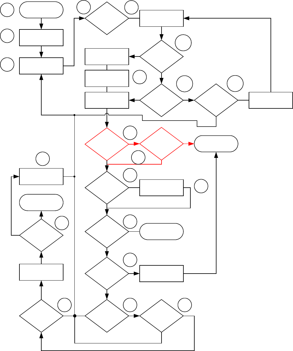
ALERT mode software flow diagram.
ALERT MODE
BOLT/NC_2
OPEN
?
LEVEL
II
?
ARMED MODE
ALERT
CONDITION
?
FIRE
CONDITION
?
POLL
TIMEOUT
?
FIRE MODE
POLL
CSU
SLEEP
INTERRUPT
OCCURRED
?
WAKEUP
TIMEOUT
?
CONTACT
ACTIVE
?
PROCESS
INTERRUPT
REGISTER
ALARM
PROCESS
ALARM
CHECK
SENSORS
16 17
17.1
18
19
21
ALERT MSG
CSU
14
15
17.2 17.3
20
22
ALL SAFE
SIGNAL
?
23
RESET ALERT
TIMEOUTS
ALERT
TIMEOUT_1
?
DISABLE ACTIVE
ALARMS
ALERT
TIMEOUT_2
?
ALARM STILL
ACTIVE
?
DISABLE ACTIVE
ALARM
ARMED MODE
24 2526
27
STILL
ALERTED
?
LOG IT
28 19A
NY
N
Y
N
Y
N
Y
N
Y
N
Y
N
Y
N
Y
N
YNYN
Y
13
Octopus ATM Defense System
Installation and Operation Guide Page 25 of 25
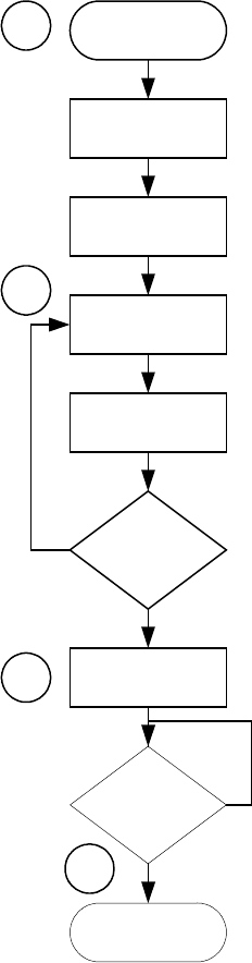
FIRE mode software diagram.
FIRE MODE
BEEP
FIRE
CHARGE PUMP
SET RELAYS
3 TIMES
?
LOGIT
PRESS TO
TEST
?
POR
29
30
31
32

Octopus ATM Defense System
Installation and Operation Guide Page A1
Appendix A
System Indications and Error Code Readout
When the door is open and the press to test button in the MCU is activated. A sequence of events occurs.
All LEDs light momentarily to indicate self test start
Discovery of CSU and registration into the ATM system
MCU beeps and blinks one green LED for every CSU in system
“BEEP” -> (X number of CSUs)
If self-test passes the MCU beeps one long beep and lights a green led
“BEEEEEEP” ->
If self-test fails the MCU beeps two short beeps and lights the red led
“BEEP” -> BEEP” ->
Then the fault or error code readout occurs.
First all leds off ->
Then followed by AREA word, SPACER word, ERROR CODE, then off and then the next code
until all error codes are readout.
i.e.
Press to Test button released
Test in progress (~10 seconds)
BEEP, BEEP two CSUs found
Spacer
BEEEEP,BEEEEP error found
Spacer
AREA WORD (MCU ONBOARD SENSOR)
Spacer
ERROR CODE MCU Low Battery Indication
Spacer
AREA WORD (MCU SENSOR INPUT)
Spacer
ERROR CODE (Generic NC input # 2 not shorted)
Spacer
Each code is readout every 2 seconds. Table 1 on the next page gives the complete error code chart in
graphical and text format. Table 2 gives problem details.

Octopus ATM Defense System
Installation and Operation Guide Page A2
AREA WORD ERROR
CODE AREA ERROR ERROR CONDITION
MCU INTERNAL SENSOR
1000 1001 MCU battery low
1000 1010 MCU tilt error
1000 1011 MCU thermal error
MCU EXTERNAL INPUTS
1100 1001 Generic NC input # 1 error
TEST MODE ONLY Power Loss (No V+) indicator
1100 1011 Generic NO input #1 error
1100 1100 Generic NC input # 2 error
TEST MODE ONLY DOOR closed indicator
1100 1110 Generic NO input # 2 error
1100 1111 Manual Fire NC/Breach error
TEST MODE ONLY All Safe signal activated indicator
CSU ONBAORD SENSORS
1110 1001 CSU battery low
1110 1010 CSU tilt error
1110 1011 CSU squib error
1110 1100 CSU thermal error
Table 1. BIST Error Readout Indication Matrix
Error Possible Cause
MCU Low Battery a) Low battery – replace
b) Faulty electronics – new unit required
MCU Tilt Error a) MCU is in horizontal position and jumper J22 (H/V)
is removed.
b) MCU is in vertical position or upside down and
jumper J22 (H/V) is installed.
MCU Thermal Error a) Unit is too hot > 70 ºC.
b) Unit is too cold < 0 ºC.
Generic NC input # 1 error a) Sensor Array cable pin # 7 is not shorted to ground
when connected.
b) Contacts reversed so that unit ground and ATM
chassis ground are not common.
c) Faulty RJ45 plug.
Generic NO input # 1 error a) Sensor Array cable pin # 7 is not open to ground
when connected.
b) Contacts reversed so that unit ground and ATM
chassis ground are not common.
c) Faulty RJ45 plug.
Generic NC input # 2 error a) Terminal block J31 is not shorted when connected.
b) Contacts reversed so that unit ground and ATM
chassis ground are not common.
c) Wire gauge too small.
Generic NO input # 1 error a) Sensor Array cable pin # 1 is not open to ground
when connected.
b) Contacts reversed so that unit ground and ATM
chassis ground are not common.
c) Wire gauge too small.
Manual Fire NC / Breach error a) Sensor Array cable pin # 2 is not shorted to ground
when connected or Terminal Block J10 not shorted
when connected.
b) Contacts reversed so that unit ground and ATM
chassis ground are not common.
a) Faulty RJ45 cable or wire gauge too small.
Octopus ATM Defense System
Installation and Operation Guide Page A3
Octopus ATM Defense System
Installation and Operation Guide Page B1
Appendix B
Optional Components
1 Door Contact Switch
Required in the basic installation kit, the door contact is a long throw normally-closed to activate. The
purpose of the door contact switch is to detect the door position as open or closed. Most ATMs already
have door contacts available that can be used; however, in the event that a door state indicator is not
available the door contact switch must be used to arm the system.
1 Smoke Generator
A simple two lead smoke canister may be purchased as an additional deterrence against robbery. When the
system activates to stain the currency, the MCU will also fire the smoke canister to fill the ATM safe with
dye staining smoke.
1 Remote Interface Monitor (RIM) – Future Option Unavailable with initial release.
A self-contained remote monitor may be purchased to allow for visual and/or aural indication. Using the
RJ-11 style 4 wire output the RIM may be conveniently placed in a suitable spot to alert service and
maintenance personnel of system status. The RIM has a buzzer and two light emitting diodes (LED’s)
which indicate the state of the system. For complete operational details please refer to the I/O guide for the
Remote Interface Monitor.
1 Remote Light Sensor – Future Option Unavailable with initial release.
A self-contained remote light sensor may be purchased to allow for penetration sensing in the event that the
ATM safe is breached through the side and or top without activation the door switch. This allows the MCU
to be placed anywhere within the ATM safe will still being able to remotely see the penetration attack.
1 Penetration Sensor
The penetration sensor is used to detect drill or torch attempts on the ATM safe through the wall onto
which it is mounted. It is a normally open circuit until penetration occurs. In order to use this device, the
MCU must be a “Nervous” system (see Appendix C). Its two leads should be attached to ground and
Manual Fire NC.
1 External Power Source – Future Option Unavailable with initial release.
A universal input (90-260 VDC) DC output power supply module. This device will allow the MCU to be
powered by line power while conserving it batteries for power outage situations.
1 External RS232 – Future Option Unavailable with initial release.
The external RS232 module will level shift the MCU UART to allow for connection to a remote PC host,
or interface with option 11. At the writing of this document the protocol interface has not been defined.
8 Sensor Array Cable / Assembly
The sensor array cable is envisioned to be a straight through cable with RJ45 termination on the end for
interface the MCU for connecting an ATM alarm suite directly into the MCU. This combination will allow
the ATM sensors to directly control the operation of the system. A PCB which translates the RJ45 inputs
into terminal blocks for ease of installation may be developed.
Octopus ATM Defense System
Installation and Operation Guide Page B1
9 Siren Module – Future Option Unavailable with initial release.
The siren module is a self powered 128 dB swept audio oscillator. It is intended as a deterrent device much
like the smoke generator to warn the crook of imminent staining. It is readily audible outside the
immediate area of the attack to alert onlookers and possible witnesses. Once activated the siren will require
battery replacement before proper operation can be insured.
10 Remote/ Local System Reset Signal – Future Option Unavailable with initial release.
The MCU has an input reserved for a signal which allows the Octopus ATM system to be reset to the
lowest threat level, allowing authorized personnel the ability to open the ATM without fear of staining the
money. This circumvents the alert time-out which usually takes from 60 to 90 minutes to allow access.
This input event is currently used in the Canadian version to allow the monitoring of the ATM bolt/lock
assembly.
11 Status Web Client Server Interface – Future Option Unavailable with initial release.
Along with the RS232 interface, a remote SBC (Single Board Computer) may be used to remotely monitor
the Octopus system and remotely command authorized access, system reset, or remote activation of a
security device like the siren or smoke.

Octopus ATM Defense System
Installation and Operation Guide Page C1
Appendix C
MCU Sensor Array Cable and RIM wiring
On the MCU there is an RJ45 connector for installation of the sensor array cable input.
Table 4 below shows the contact and compares its pin-out to standard wire coloring for Category 5
enhanced ethernet cable. If another cable is used the color schem will be different.
Pin of connector Wire Color CAT5e Contact
1 Orange Stripe NO generic input #2
2 Orange Manual Fire N/O contact
3 Green Stripe Power loss contact (optically isolated)
4 Blue System Common Ground
5 Blue Stripe Door contact N/C
6 Green All Safe contact for authorization before opening (VDC+)
7 Brown Stripe N/C generic input #1
8 Brown N/O generic input #1
RJ11 connector wiring designation.
The sensor array cable must be wired straight through. There are to types of RJ45
cables, cross-over and straight. Crossover cables cannot be used !
Also on the MCU are two RJ11 style connectors for installation of either a remote indication board or
interface into an external monitoring system. These are dry contact outputs, normally closed when
activated.
Table 5 below shows the contact and compares its pin out to standard wire coloring for 4 conductor
modular wire plugged .
2 Green Fault Relay N/C contact
3 Red Fault Relay common return
4 Yellow Alarm Relay N/C contact
5 Black Alarm Relay common return
Table 5. RJ11 connector wiring designation.

Octopus ATM Defense System
Installation and Operation Guide Page D1
Appendix D
Configuration Jumper Selection
On both the MCU and CSU a number of jumpers provided to allow for configuring operation.
Definition:
Jumper, JXX -2 pin header assembly attached to PCB.
Shunt -2 pin shorting bar used to plug onto jumper to change state from open to closed circuit/
Jumper
Silkscreen
Indicator Name Description
MCU
J4 POWER With Battery installed, and connected, installation of this jumper enables power
to the MCU.
J25 UNUSED For future expansion.
J26 UNUSED For future expansion.
J24 ENABLE
MOTION
On power-up of the MCU, if this shunt is installed (default) motion detection for
alert and fire conditions will be enabled.
If motion detection is not required, remove shunt and POWER shunt, re-install
POWER shunt to affect configuration change.
J22 TILT
SELECTION
On power-up of the MCU, if this jumper-shunt is not installed (default), the MCU
expects that it will be mounted in the vertical plane with the sensor array jack
(RJ45) facing upwards.
If horizontal mounting is required, install shunt, cycle power by removing and
installing the POWER shunt.
J3 ENABLE SQUIB
On power-up of the MCU, if this jumper-shunt is installed (default), the MCU
will upon system fire also charge and fir a Squib for use with external smoke, or
ink.
If no external squib device is required remove the shunt. No power cycling is
required.
J28 ENABLE LIGHT
On the Brazil model of ctopus, a light sensor is attached for increased
functionality (see Software Flow Diagram). Placing this shunt enable the light
detection circuitry (only if light sensor, PC1, adjacent to self-test button, is
installed). Removing it will disable the light circuitry. No power cycling is
required.
CSU
J4 POWER With Battery installed, and connected, installation of this jumper enables power
to the CSU.
J13 UNUSED For future expansion.
J14 UNUSED For future expansion.
J9 ENABLE LIGHT
SENSOR
If this jumper-shunt is installed (default), the CSU will use the light detector to
determine if the cassette lid is open or closed.
Removing this shunt disables light detection.
J11 TILT
SELECTION
On power-up of the CSU, if this jumper-shunt is not installed, the CSU expects
that it will be mounted in the vertical plane battery along the lower edge.
If horizontal mounting is required, install shunt, cycle power by removing and
installing the POWER shunt.
Jj3 ENABLE SQUIB If this jumper-shunt is installed (default), the unit is capable of firing the ink
staining system. If not installed the unit will report error during self-test.
Squib Jumper must be installed to pass self-test.
Appendix E
Octopus Installation Instructions for the
Diebold MMD Cassette
Page E1

Octopus ATM Defense System
Installation and Operation Guide
INFORMATION TO THE USER
Tools Required
The following tools(not included in the installation kit) may be required to install the Octopus ATM Defense system:
•Hand Grinder (Dremel™ Type) with cutoff saw, rotary file and ground burs.
•Common Screwdrivers
•Phillips Screwdrivers
•Razor Knife
•Hacksaw w/assorted blades
•Slip-Joint pliers
•Vice Grip, locking pliers
Page E2
1.0 Introduction
Prior to bracket installation, the Diebold MMD Cassette must be modified to
accept the Octopus ATM Defense System. The procedure includes trimming
and cutting several existing cassette components.
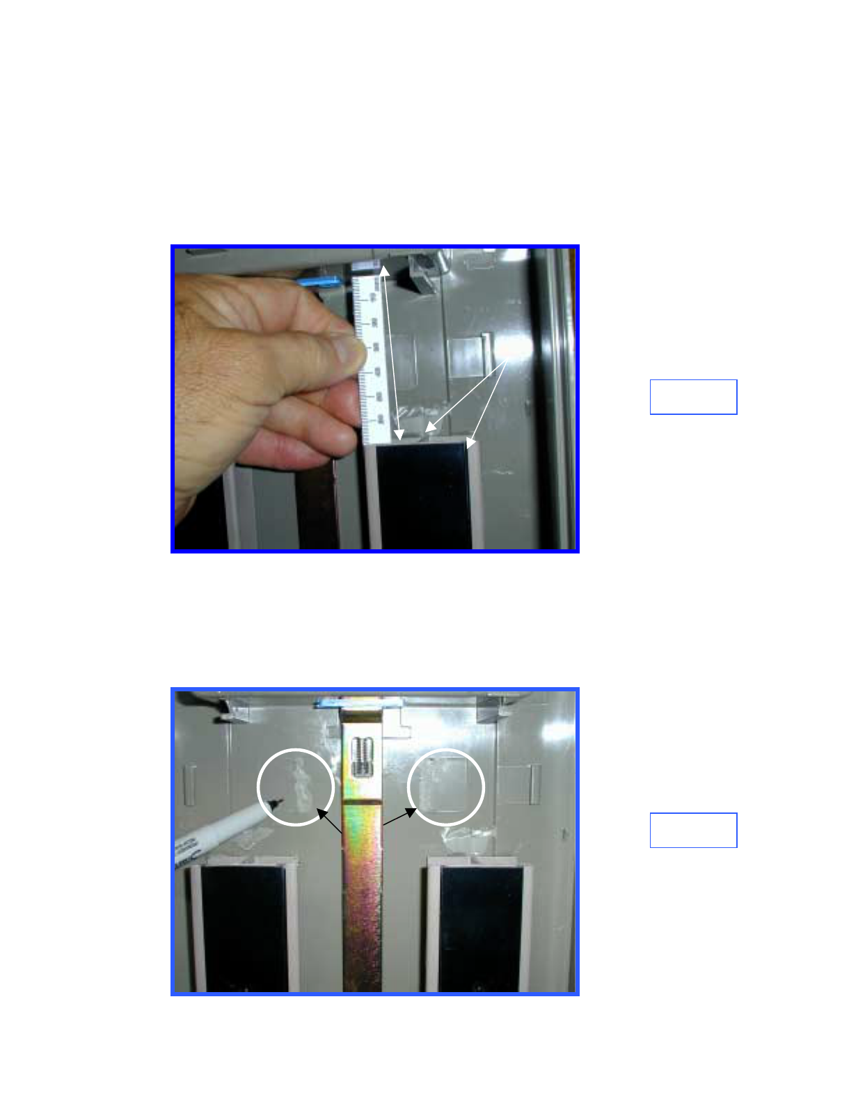
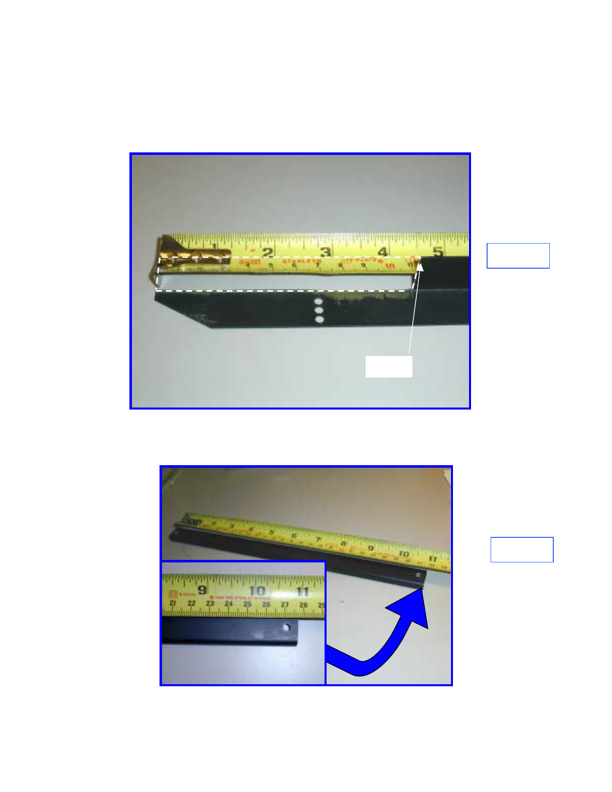
2.0 Shorten Guide Rails
Top, currency guide rails must be trimmed to provide 70mm clearance
between the rail and the inside front of the cassette (A) Figure 1. Measure
70mm, mark rails and cut rails and black inserts. Reinstall Rails.
3.0 Adhesive
Place a small amount of silicone adhesive between the edge of the rails, the
cassette top, and the black insert (B) Figure 2.
4.0 Remove Guide Rail Supports
Grind the two Rail Guide Supports flush with the Cassette top ( C) Figure 2.
C
70mm (A) B
Figure 1
Figure 2
Page E3Octopus ATM Defense System
Installation and Operation Guide
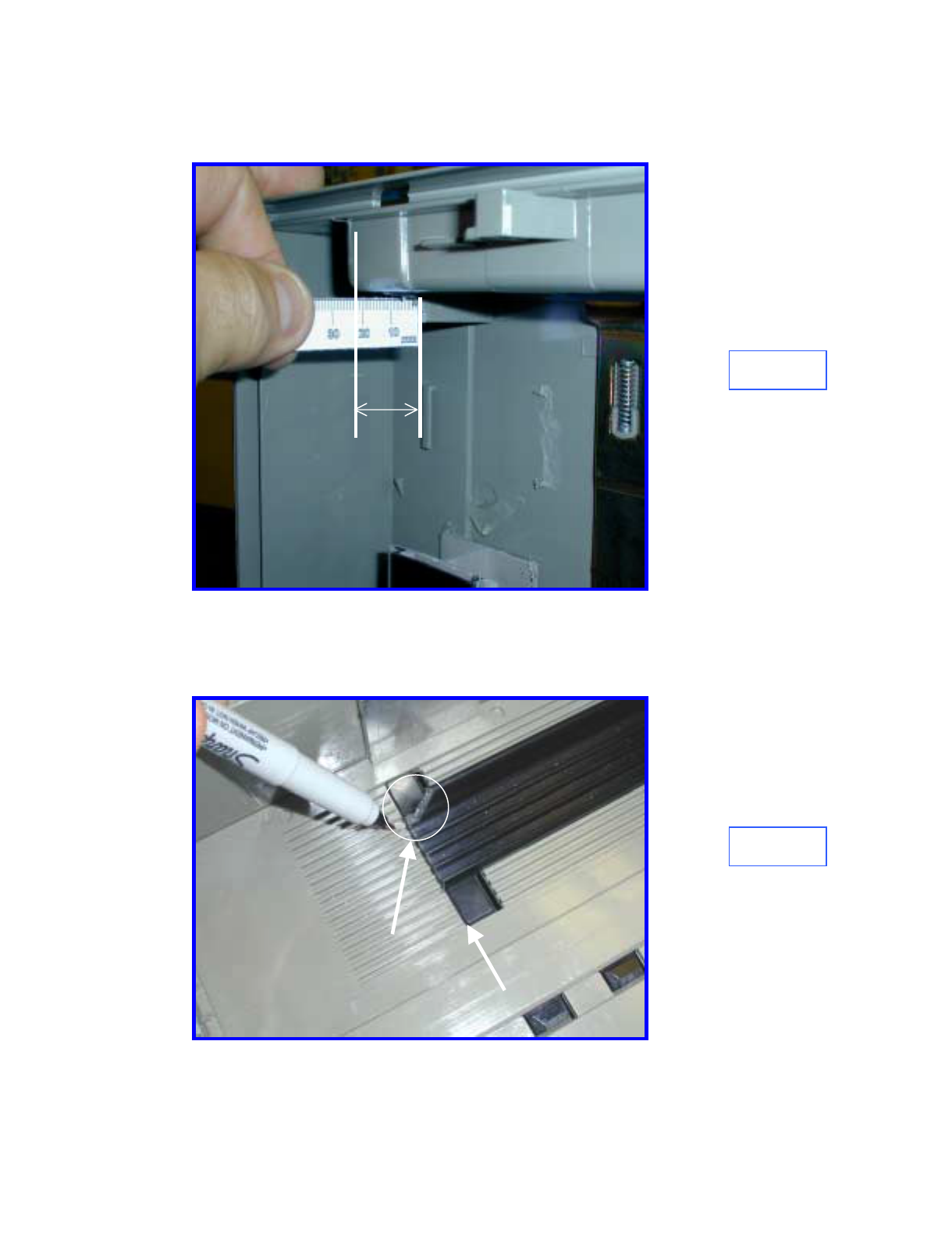
5.0 Trim
Cut-away the left rail-stop for 22mm clearance as shown in Figure 3.
22mm
6.0 Trim Bottom Currency Guides
Trim both bottom currency guides flush with the front edge of the rubber
locking pads (D) Figure 4.
Figure 3
Figure 4
7.0 Trim Bottom Left Currency Guide
Trim the left, bottom currency guide at a 45° angle (E) Figure 4 as
shown.
D
E
Page E4Octopus ATM Defense System
Installation and Operation Guide
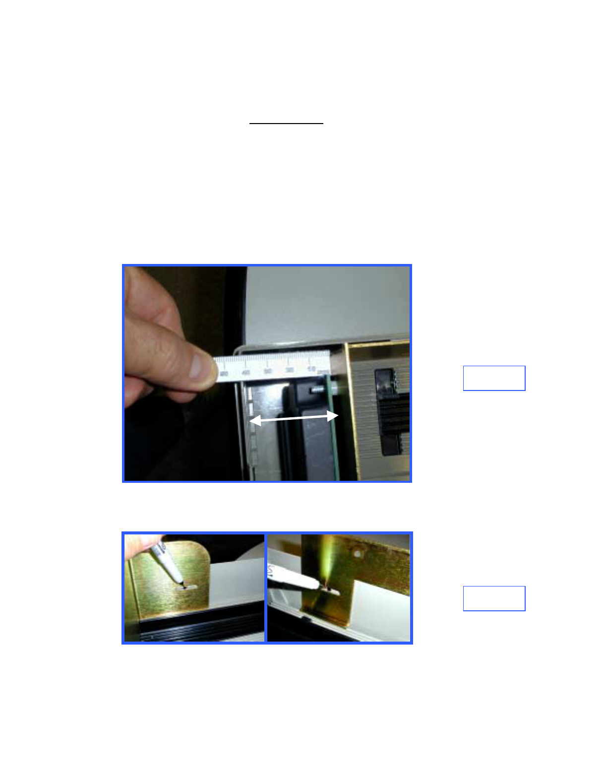
8.0 Clean Cassette Bracket Mounting area
Temporarily place the bracket assembly in the cassette, note where the three,
elongated, slotted mounting holes line up with the cassette sides. Remove the
Bracket Assembly and, (IMPORTANT)thoroughly clean the sides in the
noted area with the alcohol wipes.
Figure 5
9.0 Mark Location for Bracket Mounting Plates (3)
Place the Bracket Assembly into the cassette and set the distance between the
front of the bracket and the inside of the cassette front to 42mm Figure 5.
With the Bracket Assembly in place, mark a small dot in the center of each
elongated mounting slot, one on the left side of the cassette and two on the
right side, Figure 6
Figure 6
22mm
Page E5Octopus ATM Defense System
Installation and Operation Guide
10.0 Mount Bracket Mounting Plates
Remove the release backing from the Bracket Mounting Plates and mount the
plates with the holes over the previously applied dots as shown in Figure 6.
Figure 7
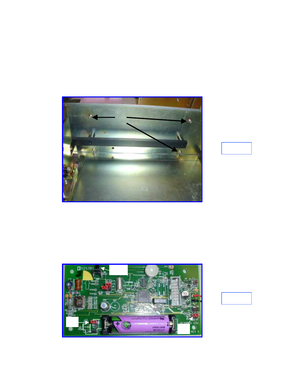
11.0 Prepare Bracket for Installation
Prepare the bracket and ink delivery system by removing the four nuts and the
CSU plastic cover. Locate J3 (Firing circuit) and J4 (Power). Remove the red
shunts and replace, bridging the two posts on each connector (Figure 7).
Replace the plastic cover and securing nuts. Make certain that the two-wire
electrical cable between the CSU electronics and the Ink Block is connected.
J4
J3
SW9
Figure 8
Page E6Octopus ATM Defense System
Installation and Operation Guide

12.0 Secure Bracket Assembly
Reinsert the Bracket assembly, install the three mounting screws with fiber
washers. Do not tighten.
Reset the distance between the front of the bracket and the inside of the
cassette front to 42mm Figure 5 and tighten the three mounting screws.
Open and close the cassette cover to check for interference. Adjust as
required.
13.0 Test Electronics
Test the CSU electronics by depressing and releasing SW9 (Figure 7). One
beep indicates that the CSU is fully functional. Two beeps indicates a failure
and requires troubleshooting. Recheck cable connections and shunt
connections (Section 11.0). This completes the installation
Page E7Octopus ATM Defense System
Installation and Operation Guide
Appendix F
Octopus Installation Instructions for the
DeLaRue MDDM Cassette
Page F1
o

INFORMATION TO THE USER
Tools Required
The following tools(not included in the installation kit) may be required to install the Octopus ATM Defense system:
•Hand Grinder (Dremel™ Type) with cutoff saw, rotary file and ground burs.
•Common Screwdrivers
•Phillips Screwdrivers
•Razor Knife
•Hacksaw w/assorted blades
•Slip-Joint pliers
•Vice Grip, locking pliers
Page F2
Octopus ATM Defense System
Installation and Operation Guide
1.0 Introduction
Prior to bracket installation, the DeLaRue MDDM Cassette must be modified
to accept the Octopus ATM Defense System. The procedure includes
trimming and cutting several existing cassette components.
2.0 Trim Currency Pressure Plate
Cut out a section of the currency pressure plate, as shown in Figure 1, to clear
the spray bar on the Octopus bracket.
3.0 Trim Currency Guides
Trim left and right currency guides flush with the mounting posts as shown in
Figures 2 and 3.
Figure 1
Figure 2
REMOVE
Page F3
Octopus ATM Defense System
Installation and Operation Guide
4.0 Trim Top Guide & Add Support
Remove top currency guide and trim to 210 mm as shown in Figure 4. Clean
metal cassette lid and top currency guide in area labeled A with an alcohol
wipe. Remove the release paper from the top rail support, and place the
smaller end into the cut end of the top rail support. Screw the top rail support
to the cassette lid while centering the cut end of the support in the lid. Press
the rail support firmly to seat the adhesive tape.
Figure 4
Figure 3
A
Page F4
Octopus ATM Defense System
Installation and Operation Guide
5.0 Remove Screws
Remove, and retain, the three securing screws, B, Figure 5.
Figure 5
B
6.0 Prepare Bracket for Installation
Remove the four nuts and remove the CSU plastic cover. See Figure 6.
Locate J3 (Firing circuit) and J4 (Power). Remove the red shunts and replace,
bridging the two posts on each connector. Replace the plastic cover and
securing nuts. Make certain that the two-wire electrical cable between the
CSU electronics and the Ink Block is connected.
J4 J3
SW9
Figure 6
Page F5
Octopus ATM Defense System
Installation and Operation Guide
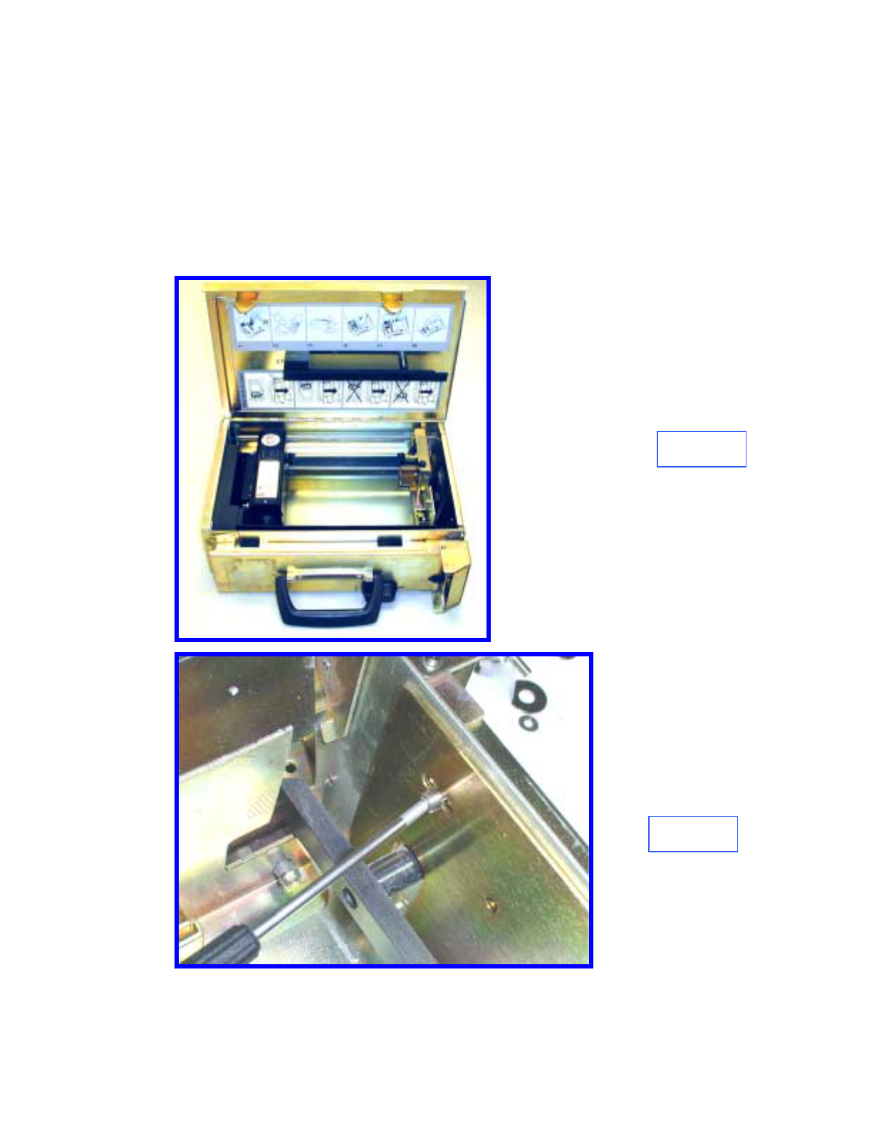
Figure 7
Figure 8
7.0Install Bracket Assembly
Install the Octopus bracket assembly into the cassette as shown in Figure 7.
Slide the bracket forward to maximize the currency capacity, replace and
tighten the three screws (Figure 8). Note: it may be easier to replace the
screws if they are temporarily fixed the the tool tip with tape.
Slide the Currency Pressure Plate, close and open the cassette lid to make sure
that there is no interference.
Page F6
Octopus ATM Defense System
Installation and Operation Guide

8.0 Test Electronics
Test the CSU electronics by depressing and releasing SW9 (Figure 7). One
beep indicates that the CSU is fully functional. Two beeps indicates a failure
and requires troubleshooting. Recheck cable connections and shunt
connections (Section 6.0). This completes the installation
Page F7
Octopus ATM Defense System
Installation and Operation Guide
Appendix G
Octopus Installation Instructions for the
Perto “A” C-130 Cassette
Page G1

INFORMATION TO THE USER
Tools Required
The following tools(not included in the installation kit) may be required to install the Octopus ATM Defense system:
•Hand Grinder (Dremel™ Type) with cutoff saw, rotary file and ground burs.
•Common Screwdrivers
•Phillips Screwdrivers
•Razor Knife
•Hacksaw w/assorted blades
•Slip-Joint pliers
•Vice Grip, locking pliers
Page G2
Octopus ATM Defense System
Installation and Operation Guide
1.0 Introduction
Prior to bracket installation, the Perto Cassette must be modified to accept the
Octopus ATM Defense System. The procedure includes trimming and cutting
several existing cassette components.
2.0 Modify Currency Guides
Remove the left (looking from the front) currency guide. Remove 11 cm of
the vertical portion flush with the horizontal portion (Figure 1).
3.0 Modify Top Guide Length
Trim the top currency guide rails to 278 mm length (Figure 2).
Figure 1
Figure 2
11 cm
Page G3
Octopus ATM Defense System
Installation and Operation Guide
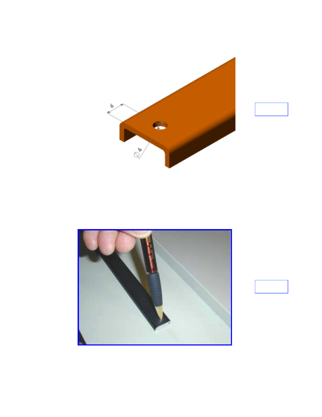
4.0 Drill Top Guides
Drill a 4 mm diameter centered hole 6 mm back from the cut end of the guide
rail on both pieces (Figure 3).
Figure 4
Figure 3
5.0 Drill Lid
Place the currency guides over the rear screws, making sure that the rails are
parallel with the cover mark through the drilled hole onto the lid. Drill the
holes through with a 4 mm drill bit (Figure 4).
Page G4
Octopus ATM Defense System
Installation and Operation Guide
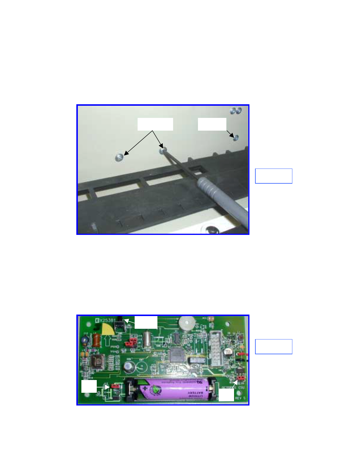
Figure 5
6.0 Replace Top Guides
Reinstall the screws, washers nuts and guide rails. Adjust the height of the
guide rails for the local currency.
7.0 Bracket Securing Screws
Remove and retain the four forward (leave the rear screws in place)screws
holding the left and right external plastic guide rails (Figure 5).
REMOVE LEAVE
8.0 Bracket Preparation
Prepare the bracket and ink delivery system by removing the four nuts and the
CSU plastic cover. Locate J3 (Firing circuit) and J4 (Power). Remove the red
shunts and replace, bridging the two posts on each connector (Figure 6).
Replace the plastic cover and securing nuts. Make certain that the two-wire
electrical cable between the CSU electronics and the Ink Block is connected.
Figure 6
J4 J3
SW9
Page G5
Octopus ATM Defense System
Installation and Operation Guide
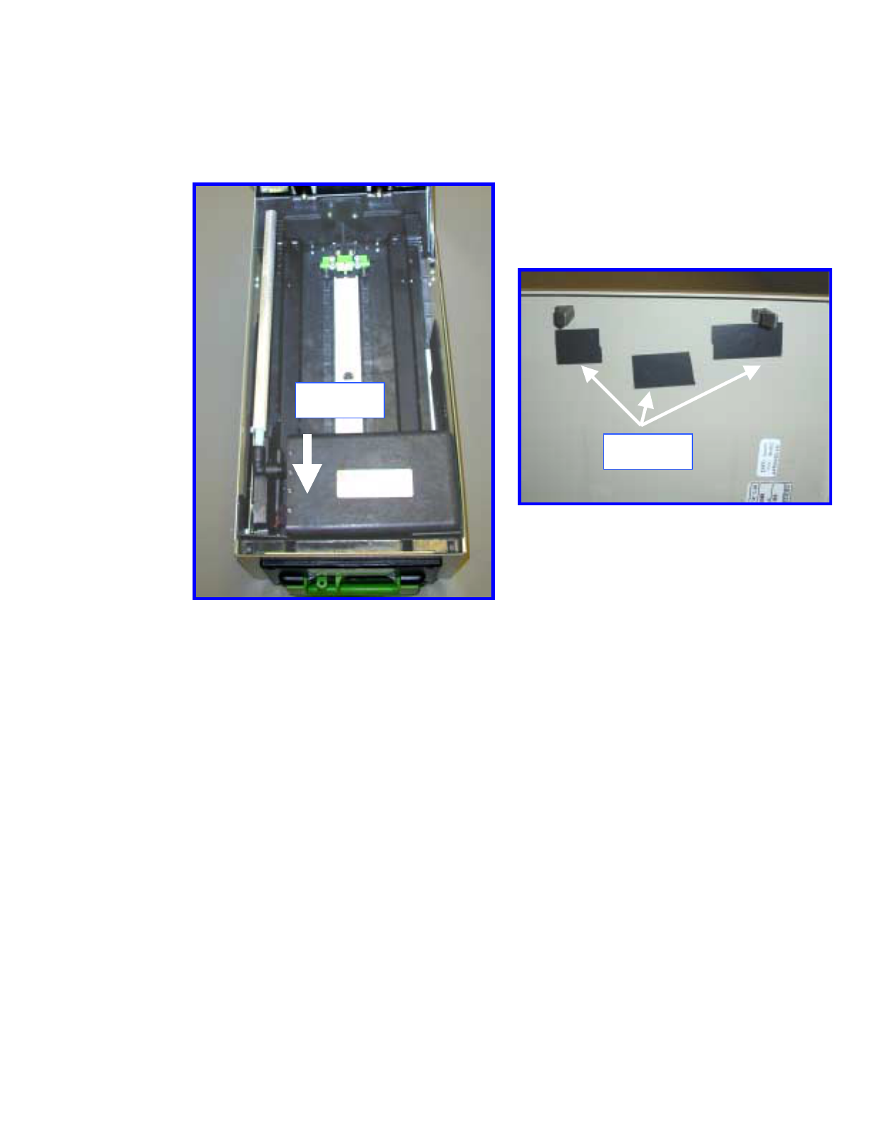
Figure 7
9.0 Install Bracket
Install the bracket assembly into the cassette with the bracket seated firmly on
the bottom and positioned as far to the front of the cassette as possible (Figure
7). Replace the four screws to secure the bracket and external plastic guide
rails.
Figure 8
10.0 Seal Lid Holes
Cover the three holes on the cassette lid with opaque tape (electrical tape) to
shield the CSU light sensor when the lid is closed (Figure 8).
11.0 Check Fit
Close and open the lid several times to make sure that there is no mechanical
interference.
12.0 Test Electronics
Test the CSU electronics by depressing and releasing SW9 (Figure 6). One
beep indicates that the CSU is fully functional. Two beeps indicates a failure
and requires troubleshooting. Recheck cable connections and shunt
connections (Section 8.0)
Page G6
Octopus ATM Defense System
Installation and Operation Guide
Appendix H
Octopus Installation Instructions for the
DeLaRue NMD Cassette
Page H1

INFORMATION TO THE USER
Tools Required
The following tools(not included in the installation kit) may be required to install the Octopus ATM Defense system:
•Hand Grinder (Dremel™ Type) with cutoff saw, rotary file and ground burs.
•Common Screwdrivers
•Phillips Screwdrivers
•Razor Knife
•Hacksaw w/assorted blades
•Slip-Joint pliers
•Vice Grip, locking pliers
Octopus ATM Defense System
Installation and Operation Guide Page H2
1.0 Introduction
Prior to bracket installation, the DeLaRue NMD Cassette must be modified to
accept the Octopus ATM Defense System. The procedure includes trimming
and cutting several existing cassette components.
2.0 Modify Guide Rails
Mark both aluminum guide rails at the edge of the plastic supports as shown
in Figure 1.
Remove the two aluminum currency guide rails and positioning springs and
cut off the forward portion of the rails as marked in Figure 1.
Make an inset in the inside, front edge of the cut rails as shown 33 mm from
the rear of the aluminum and 28 mm from the INSIDE edge as shown in
Figure 2.
Figure 1
Figure 2
REMOVE
REMOVE
Octopus ATM Defense System
Installation and Operation Guide Page H3
5.0 Modify Springs
Trim the straight spring extension and place a hook in the end as shown in
Figure 3. This is to accommodate the shortened guide rail.
6.0 Re-install Guides
Replace currency guides and springs. Adjust separation and height for local
currency size. Guide installation is shown in Figure 4.
Figure 3
Figure 4
Original Spring
Modified Spring
Octopus ATM Defense System
Installation and Operation Guide Page H4
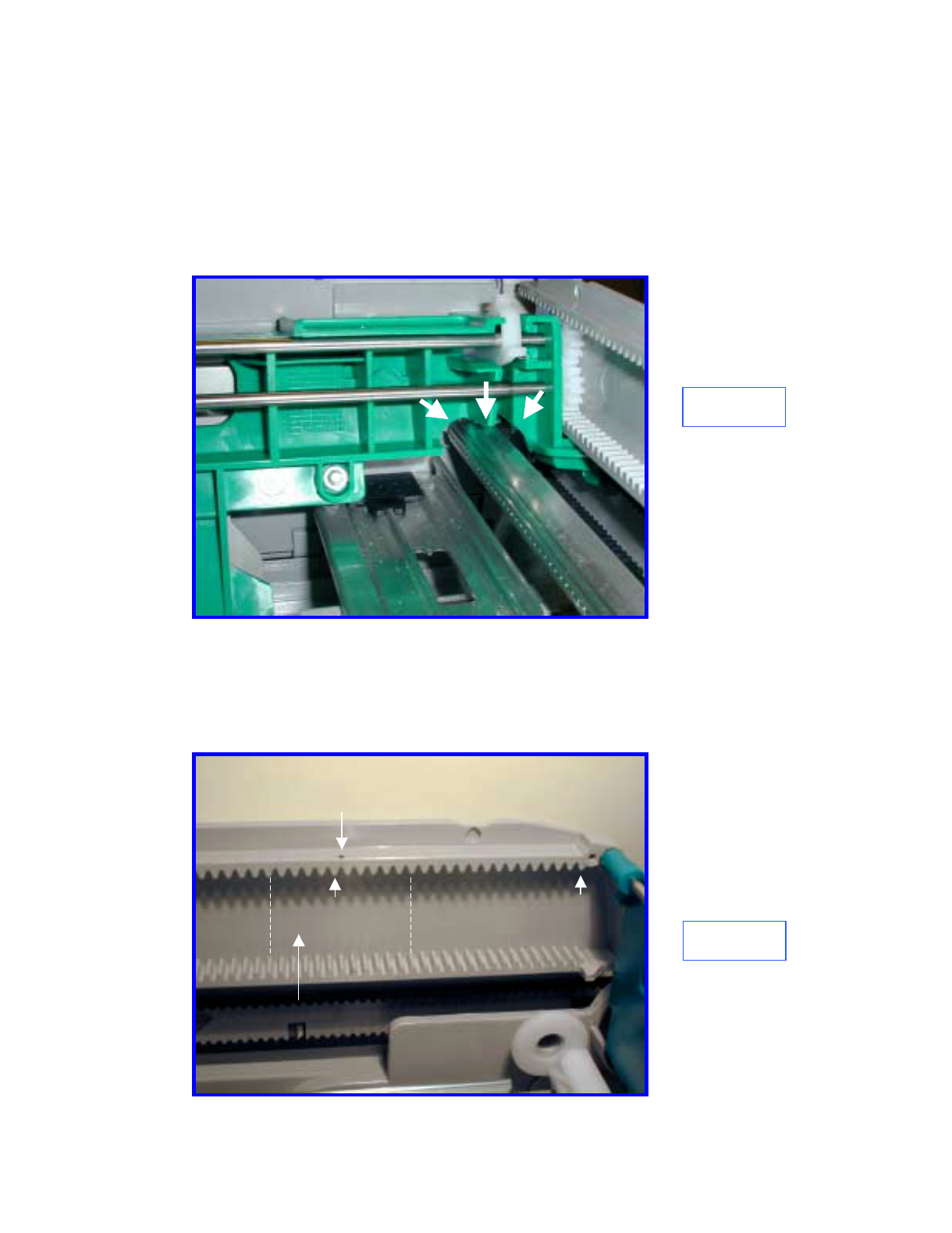
Figure 5
7.0 Modify Currency Pressure Plate
Using a rotational cutter, modify the green plastic pressure plate (Figure 5).
Temporarily place the spray bar and bracket in place to assure that there is no
interference as the plate slides from from to back. The spray bar should be
positioned within a few millimeters of the currency position.
Figure 6
8.0 Prepare for Bracket Mounting Pad Installation
Place a small dot between the 20th and 21st tooth on the gear rack, both sides,
as shown in Figure 6. Thoroughly clean the area between the dotted white
lines with an alcohol wipe, both sides.
1
21
DOT
Clean Area
Octopus ATM Defense System
Installation and Operation Guide Page H5
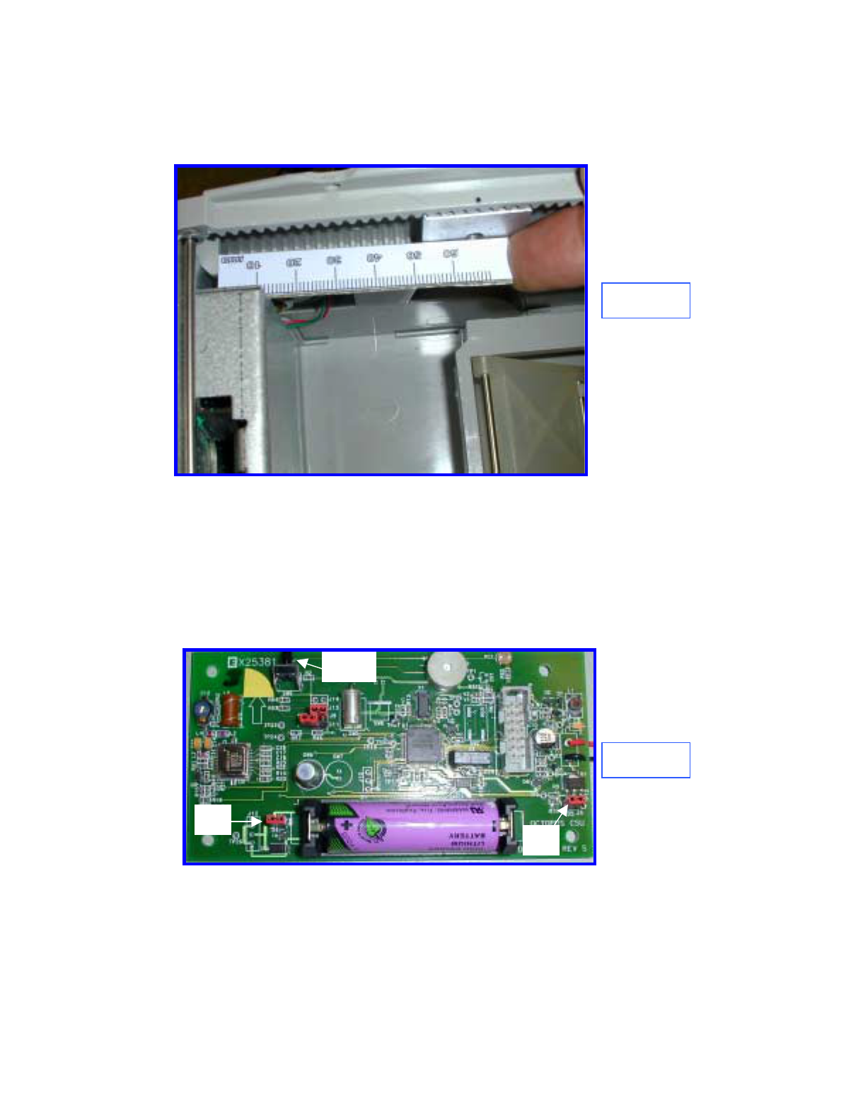
9.0 Install Bracket Mounting Pads
Remove the release backing from the Bracket Mounting Plates and mount the
plates with the holes centered over the dots created in Section 8.0. See Figure
7.
Figure 7
12.0 Secure Bracket Assembly
10.0 Prepare Bracket for Installation
Prepare the bracket and ink delivery system by removing the four nuts and the
CSU plastic cover. Locate J3 (Firing circuit) and J4 (Power). Remove the red
shunts and replace, bridging the two posts on each connector (Figure 6).
Replace the plastic cover and securing nuts. Make certain that the two-wire
electrical cable between the CSU electronics and the Ink Block is connected
(Figure 8).
J4 J3
SW9
Figure 8
Octopus ATM Defense System
Installation and Operation Guide Page H6
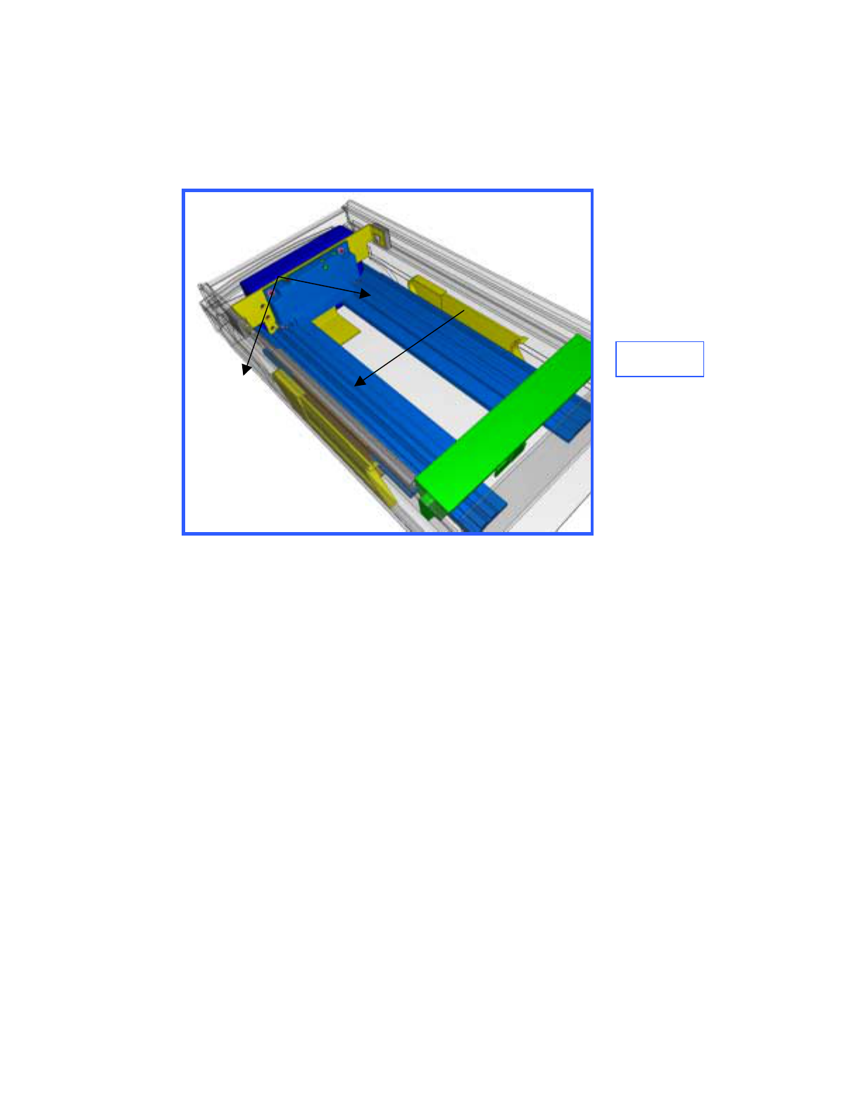
11.0 Clean Cassette Bracket Mounting area
Temporarily place the bracket assembly in the cassette(Figure 9) note where
the bracket bottom flange touches the cassette bottom. Remove the bracket
and thoroughly clean the area with the alcohol wipes.
12.0 Install Bracket Assembly
Remove the release paper from bracket flange and install the bracket making
sure that the bracket assembly clears the green latching mechanism on the
front of the cassette. Install the two screws and tighten to secure the bracket.
Figure 9
Clean area
with alcohol
Screws
Octopus ATM Defense System
Installation and Operation Guide Page H7
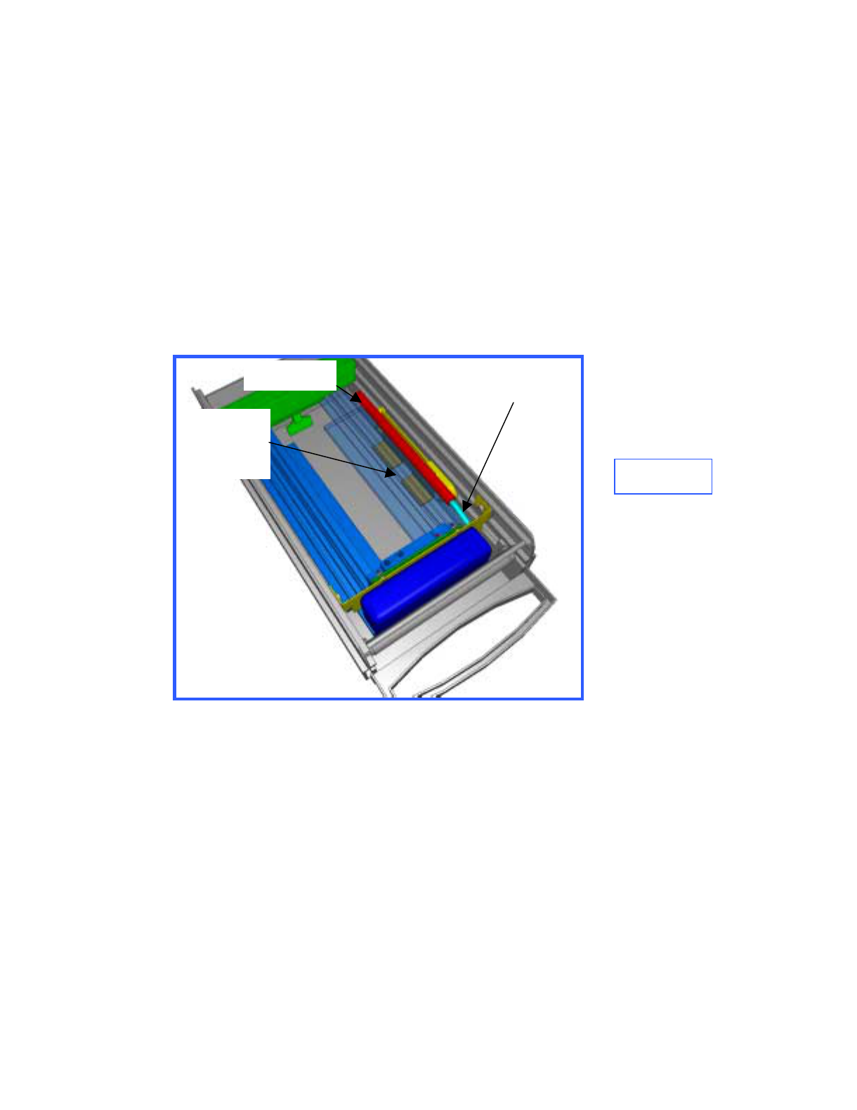
13.0 Install Spray Bar Assembly (Figure 10)
Clean the area under the aluminum currency guides with alcohol. Remove the
release paper from the spray bar bracket.
Connect the ink delivery tube (on the spray bar) to the quick-connect elbow
fitting on the ink block. Make sure that the tube is fully inserted and locked
into the fitting. Rotate the spray bar bracket legs around the aluminum
currency guides and position the spray bar on the bottom of the cassette and
firmly push down to seat. Note: make sure that the spray bar clears the
currency by 1 –2 mm.
Clean
with
alcohol
Ink Delivery Tube
Spray Bar
Figure 10
13.0 Check Fit
Close and open the lid several times to make sure that there
is no mechanical interference.
12.0 Test Electronics
Test the CSU electronics by depressing and releasing SW9 (Figure 8). One
beep indicates that the CSU is fully functional. Two beeps indicates a failure
and requires troubleshooting. Recheck cable connections and shunt
connections (Section 10.0)
Octopus ATM Defense System
Installation and Operation Guide Page H8
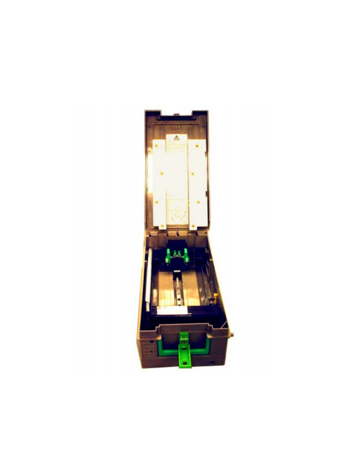
Appendix I
Octopus Installation Instructions for the
NCR Cassette
Page I1

Page 2 of 8
INFORMATION TO THE USER
Tools Required
The following tools(not included in the installation kit) may be required to install the Octopus ATM Defense system:
•Hand Grinder (Dremel™ Type) with cutoff saw, rotary file and ground burs.
•Common Screwdrivers
•Phillips Screwdrivers
•Razor Knife
•Hacksaw w/assorted blades
•Slip-Joint pliers
•Vice Grip, locking pliers
•4MM HEX Driver
Page I2Octopus ATM Defense System
Installation and Operation Guide
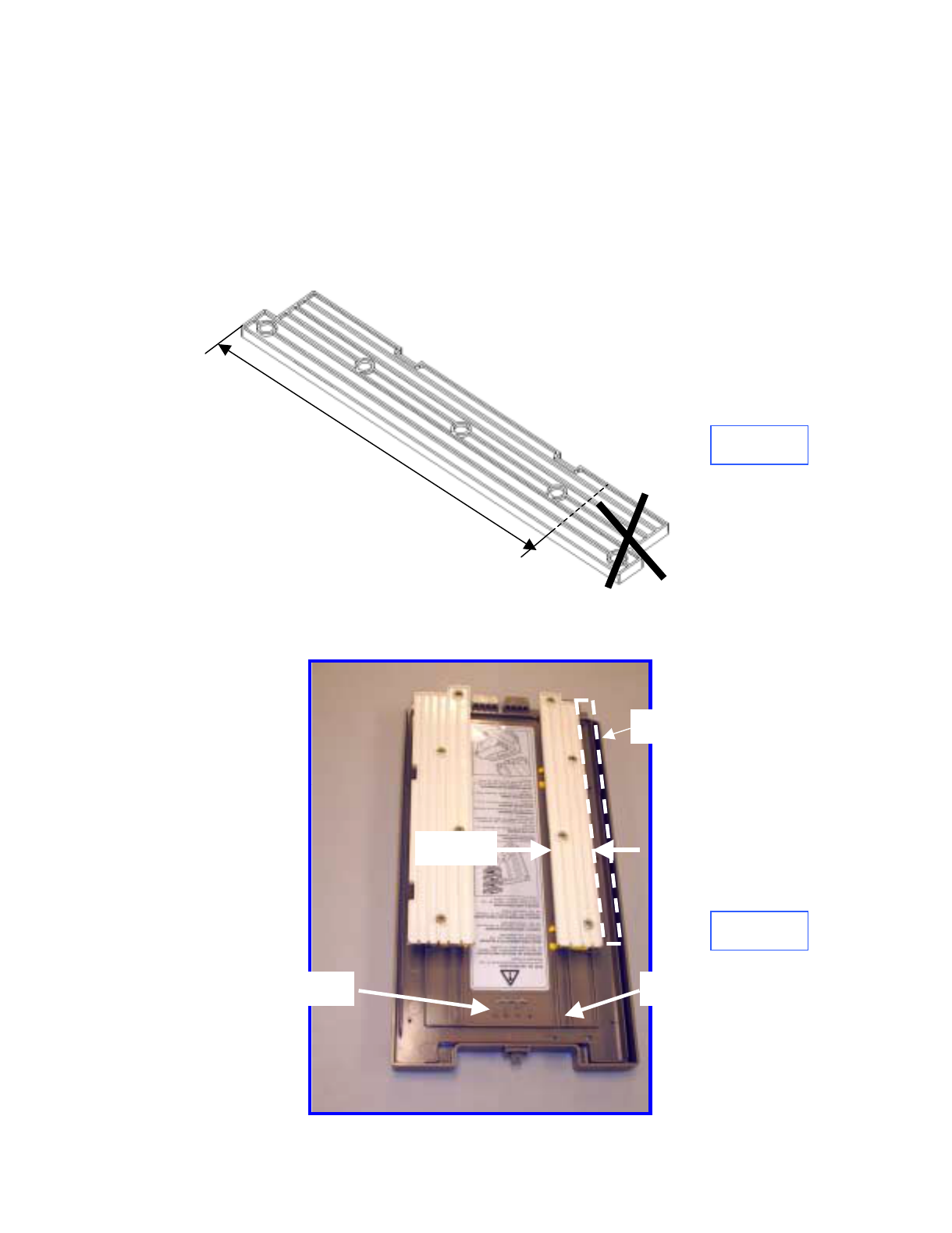
1.0 Introduction
Prior to bracket installation, the NCR Cassette must be modified to accept the
Octopus ATM Defense System. The procedure includes trimming and cutting
several existing cassette components.
Figure 1
Figure 2
2.0 Modify cover
Remove the cover from the cassette. Remove the top currency guides and
trim-off the FRONT portion of each to make the rails 265mm long (Figure 1).
FRONT
Referring to Figure 2, trim the outside edge of the rail identified to make the
rail 37mm wide.
265mm
37mm
Remove
Remove Raised Rib
Page I3Octopus ATM Defense System
Installation and Operation Guide
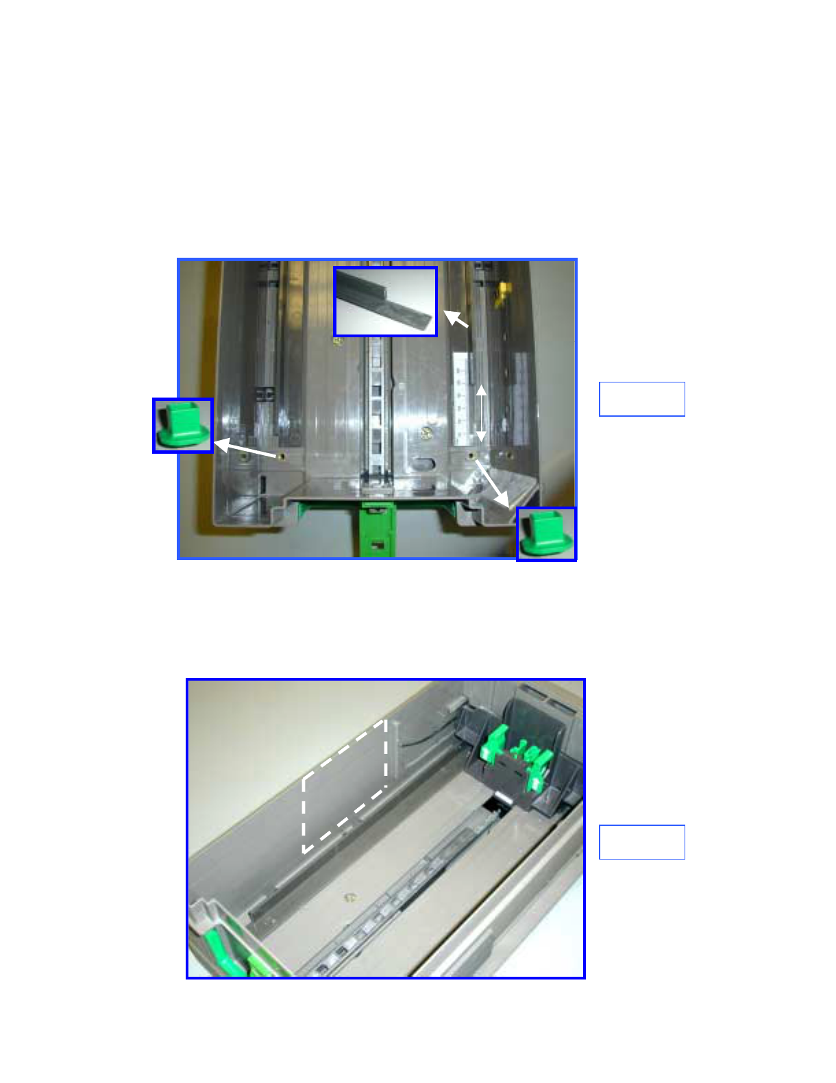
Remove enough of the center raised boss (Figure 2) until the boss is lower that
the surrounding raised rib.
Reinstall top rail guides, this completes the cover modification.
3.0 Modify bottom guide
Remove the two, green, guide securing screws. Remove the right bottom
currency guide and cut away 47mm of the front vertical portion flush with the
horizontal portion (Figure 3).
Figure 3
Reinstall the currency guides, do not reinstall green
securing screws.
Remove
Remove
47mm
4.0 Clean Securing Pad Mounting Area
Thoroughly clean the area identified in Figure 4 with an alcohol wipe.
Figure 4
CLEAN
Page I4Octopus ATM Defense System
Installation and Operation Guide
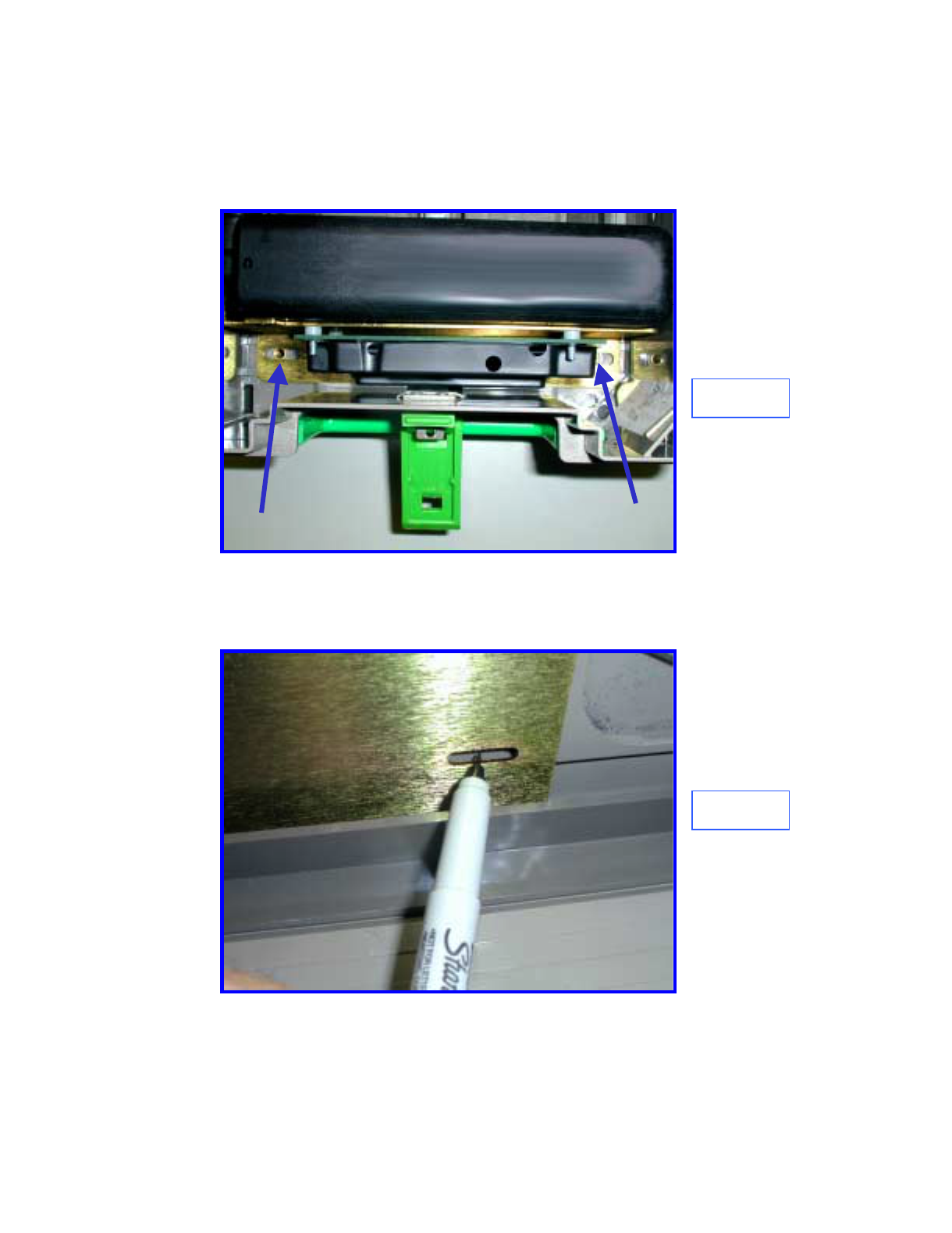
Figure 5
5.0 Install Side Securing Pad
Place the Octopus bracket in the cassette with the forward slotted holes
centered over the 5mm tapped holes in the bottom (Figure 5).
Figure 6
With the bracket aligned with the tapped holes, and making sure that the
bracket is horizontal, place a mark on the cassette wall centered on the slotted
hole in the bracket side under the spray bar (Figure 6).
Page I5Octopus ATM Defense System
Installation and Operation Guide
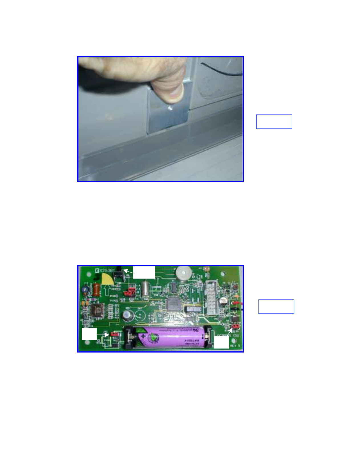
Remove the bracket, remove the release paper from the securing pad and
install with the hole centered over the marked dot on the cassette wall (Figure
7).
Figure 7
6.0 Prepare Bracket for Installation
Prepare the bracket and ink delivery system by removing the four nuts and the
CSU plastic cover. Locate J3 (Firing circuit) and J4 (Power). Remove the red
shunts and replace, bridging the two posts on each connector (Figure 8).
Replace the plastic cover and securing nuts. Make certain that the two-wire
electrical cable between the CSU electronics and the Ink Block is connected.
Figure 8
J4 J3
SW9
Page I6Octopus ATM Defense System
Installation and Operation Guide
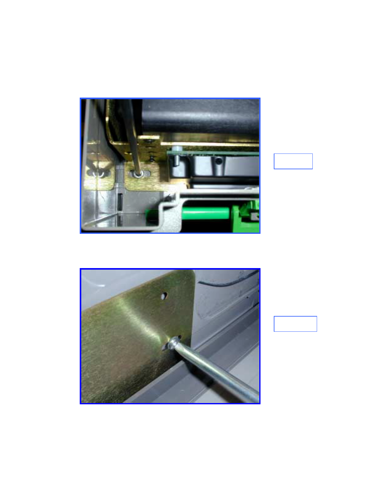
7.0 Install Bracket Assembly
Place the bracket in the cassette and install the two 5mm mounting screws
through the slotted holes in the bracket front. Make sure that the bracket is
adjusted to the left, touching the securing pad. Tighten the screws (Figure 9).
Figure 9
Using the 10-32 screw, attach the bracket to mounted securing pad (Figure
10).
Figure 10
Page I7Octopus ATM Defense System
Installation and Operation Guide

8.0 Check Fit
Close and open the lid several times to make sure that there
is no mechanical interference.
9.0 Test Electronics
Test the CSU electronics by depressing and releasing SW9 (Figure 8). One
beep indicates that the CSU is fully functional. Two beeps indicates a failure
and requires troubleshooting. Recheck cable connections and shunt
connections (Section 6.0). This completes the installation
Page I8Octopus ATM Defense System
Installation and Operation Guide

Octopus ATM Defense System
Installation and Operation Guide Page J1
Appendix J
Mode Jumper Selection
On both the MCU and CSU two of jumpers provided to allow for selecting mode of operation. Addressed
first is the H/V jumper. These jumpers are currently not populated.
If the H/V jumper is installed the unit must be placed horizontal with electronics facing downwards !
There are two other jumpers for selecting operating mode. On the MCU these jumpers are J25 and J26.
On the CSU these jumpers are J13 and J14. In order to change these configurations the unit battery must
be removed for a complete power-on reset. Table 5 below details the mode differences and Figure 6 shows
the physical location of the jumpers on the MCU and CSU.
MCU Jumpers Mode Differences from normal operation
J25 J26
off off LEVEL
IV (US) Operation as described within this document (US VERSION).
off on LEVEL
III (CA) Operation as described within Appendix J (LEVEL III CA VERSION)
on off LEVEL
V (BZ) Operation as described within Appendix K (LEVEL V BZ VERSION)
on on LEVEL
II OPERATION NOT DEFINED
CSU Jumpers
J13 J14
off off Normal Operation as described within this document (US VERSION).
off on Not
Assigned
on off LEVEL
V (BZ) Operation as described within Appendix K (BRAZIL VERSION)
on on Not
Assigned
Table 5. Product Mode Configuration jumper settings.
NEED CLOSEUP PICTURE OF JUMPERS HERE

Octopus ATM Defense System
Installation and Operation Guide PageT1
Appendix T
TEST MODE
I. Definitions:
Switch Terminal Markings
Normally Open, NO or N/O: When the switch is not in an active state (plunger not depressed, switch not
thrown, spring not tensioned). The resistance between the common terminal
and the NO terminal, when measured with an Ohm-meter should be open.
Normally Closed, NC or N/C: When the switch is not in an active state (plunger not depressed, switch not
thrown, spring not tensioned). The resistance between the common terminal
and the NC terminal, when measured with an Ohm-meter should be closed.
Common or COM The terminal which has a common connection to either the NO or NC terminal
when the switch is not active, and to the other terminal when the switch is a
activated. This contact should always be used to connect the system ground.
Most mechanical switches whether they are NO or NC have both terminals available for connection.
II. General MCU Test Mode Operation:
1. Place unit in TEST mode by holding the POST button while powering the unit.
2. See page T7 for software flow diagram.
3. If unit is tilted beyond 50 degrees for 2 seconds it will beep 1 time.
4. If unit senses continuos motion for 15 seconds it will beep 2 times.
5. If there is a transition of light (dark to light, or light to dark) the unit will beep 3 times (if light sensor is
installed and active).
6. If the unit senses thermal shock & senses temperature below 0 deg C or above 70 deg C the unit will beep 5
times.
7. If a sensor is activated (DOOR, BOLT, ALARM SUITE, BREACH, et al) the unit will display a hex code on
the LEDs for the highest priority sensor which is active. This process can take ~ 1 second from event to
display.
Test Mode uses a hierarchy to manage multiple active inputs. This is not an assignment of importance;
however, it will mask the lower priority inputs until higher priority inputs are cleared. See Table 3 for
error code resolution.
Available Sensor Array Cable Inputs: Terminal Block Inputs: (Referenced top-up, left to right)
Pin 1 Manual Fire NC/Breach Pin 1 Generic NC Input #2
Pin 2 Generic NO Input #2 Pin 2 Ground
Pin 3 Power Loss V++ Pin 3 Power Loss V++
Pin 4 Ground Pin 4 Manual Fire NC/Breach
Pin 5 ATM Door Switch Pin 5 ATM Door Switch
Pin 6 All Safe Signal Pin 6 Ground
Pin 7 Generic NC Input #1
Pin 8 Generic NO Input #1
8. If no sensors are active the unit will blink the red LED ~ 1 time per second: When the unit is received it will
blink its red LED 1 time per second. ( , , )
9. Power Loss detection can be enabled by applying 5 VDC to the power loss input on the terminal block or the
sensor array cable.
10. Sensor array input NC_1 detection can be enabled by shorting pin 7 of the sensor array cable to pin 4.
11. Beeping and LED display can occur simultaneously.

Octopus ATM Defense System
Installation and Operation Guide PageT2
12. Pressing the POST button while in Test mode releases the unit from test mode.
Procedure:
Cassette staining units should be complete and MCU position testing complete per installation instructions.
1. Insure that all cassette staining units have their ink blocks disconnected. The ink block wiring must be
replaced with a shorting shunt that was provided when the unit shipped. Without the shorting bars the
CSUs will not pass self-test !
2. Install all used sensor inputs to MCU. (Use caution to make sure polarity is correct as the system uses a
common ground.)
SENSOR INPUT
LOCATION Octopus Level II
(Canadian) Octopus Level III
(US) Octopus Level V
(Brazil)
ATM DOOR
Terminal Block pin 5 &
Ground pin 6.
Or
Array Cable pin 5 &
Ground pin 4
Required.
Connect to door contact
switch.
Required.
Connect to door contact
switch.
Required.
Connect to door contact
Switch.
Generic NC input # 2
Terminal Block pin 1 &
Ground pin 2.
Required
Connect to bolt position
indicator.
Required
Will cause BIST error on
POST.
Required.
Connect to ATM alarm suite,
alerts system only.
Generic NC input # 1
Array Cable pin 7 &
Ground pin 4
Optional
Does not cause BIST error
on POST.
Optional
Does not cause BIST error
on POST.
Required.
Connect to ATM alarm suite,
alerts the system.
Generic NO input # 2
Array Cable pin 2 &
Ground pin 4
Optional
Does not cause BIST error
on POST.
Optional
Does not cause BIST error
on POST.
Required.
Connect to ATM alarm suite,
alerts the system.
Generic NO input # 1
Array Cable pin 8 &
Ground pin 4
Optional.
Does not cause BIST error
on POST.
Optional.
Does not cause BIST error
on POST.
Required.
Connect to ATM alarm suite,
alerts the system.
Power Loss input
Terminal Block pin 3 &
Ground pin 2.
Or
Array Cable pin 3 &
Ground pin 4
Optional.
Does not cause BIST error
on POST.
Optional.
Does not cause BIST error
on POST.
Required.
Connect to ATM alarm suite
power output +5 VDC, alerts
the system.
All Safe signal
Array Cable pin 6 &
Ground pin 4
Optional.
Does not cause BIST error
on POST.
Optional.
Does not cause BIST error
on POST.
Required.
Connect to authorized
opening detection, resets the
system only.
Manual Fire NC/Breach
Terminal Block pin 4 &
Ground pin 2 or 6.
Or
Array Cable pin 1 &
Ground pin 4
Optional.
Will cause BIST error on
POST.
Required.
Will cause BIST error on
POST.
Required.
Terminal Block or Sensor
Array Cable connected to
breach sensor detection, fires
the system. If unused
Terminal block pin 4 must be
shorted to ground with a buss
strap.
Table 1. External sensor input selection table.
Required means that the input must be provided for either by installation of the sensor or using the
provided buss-bar to short the contacts. Required contacts are monitored by the BIST errors during
POST.
Optional means that input may be used; however, no BIST error will occur if contact is mis-wired.
All inputs are testable using the test mode.

Octopus ATM Defense System
Installation and Operation Guide PageT3
3. Activate or select function for onboard sensors.
ON BOARD SENSOR Canadian U.S. Brazil
Light Sensor Not placed Not placed Required
Function selected by jumper
on J2
Tilt Sensor Required
Built in Required
Built in Required
Built in
Thermal Sensor Required
Built in Required
Built in Required
Built in
Motion Sensor Optional
Function selected by jumper
on J24. The default
condition is motion enabled.
Optional
Function selected by jumper
on J24. The default condition
is motion enabled
Optional
Function selected by jumper
on J24. The default condition
is motion enabled
Table 2. On-board sensor input selection table.
4. Pull the signal wires to a convenient place for testing the operation of the system. Depending on the
configuration of the switch the mechanical contacts to be used should be the common connection (usually
marked COM) and the N/O connection (usually marked NO or N/O).
In cases where the indicator switch must be closed (activated) when the door is open the normally closed contact
(usually marked NC or N/C).
5. To place the unit into TEST mode, hold down the Press-To-Test-Button while removing and reinstalling the
power jumper. Unit will beep 5 times quickly to signal the mode. If the light sensor is attached the unit will
see light and beep three times. This mode will last 10 minutes unless the user presses the POST button to
release the unit to normal mode.
6. In its shipped configuration, a buss-bar will be shorting the Manual Fire/Breach input and the Generic NC
input 2. If the unit has no connections or if all connections are in normal STANDBY mode configuration the
unit will blink its red LED 1 time per second. ( , , )
TEST MODE LASTS FOR 10 MINUTES. If during the test the red LED stops blinking, you must remove the
cover, and hold the Press-To-Test-Button while removing/re-installing the power jumper.
7. If any sensor is not in normal condition the LED will display a hex code of the highest priority sensor. With
the following exceptions:
a) Power Loss Detection is not enabled unless +2 to5 VDC is first applied between terminal
block position 3 and ground (position 2 or 6).
b) Generic NC input #1 is ignored unless the Generic NC input # 1 is enabled is enabled by
first shorting pin 7 to pin 4 on the sensor array cable.
Power detection and Generic NC input # 1 must be re-enabled each time the unit is placed in test mode.
If Power Detection is enabled and all inputs except the shorting bar are removed is displayed.
If Generic NC 1 is used is and all inputs except the shorting bar are removed is displayed.
8. Using table 3 below resolve any improper configuration.
The system is wants to see the default STANDBY Mode conditions:
• Door Open
• Generic NC input 2 open
• Manual Fire NC/Breach Closed (buss-bar)
• Generic NC input 1 closed if sensor array inputs are used (see step 7).
• +2 to 5 VDC on Power Loss input either terminal block or sensor array cable if power
detection is to be used (see step 7).

Octopus ATM Defense System
Installation and Operation Guide PageT4
Priority LED Code HEX Active Sensor Detected Expected Input w/ system deactivated.
1 1101 0xD ATM_DOOR Normally Open contact input from door
switch.
2 1100 0xC Generic NC input 2
(Terminal Block Only) Open contact input when bolt is open or
system is in standby – no alarm exists
3 1110 0xE Generic NO input 2 Closed contact input when system is in
standby – no alarm exists
4 1011 0xB Generic NO input 1 Closed contact input when system is in
standby – no alarm exists
5 0101 0x5 All Safe Signal Open contact input when system in standby
for test mode only. Signal transition from
closed to open condition activates this input.
LEDs will blink on for ~ 1 second every time
a transition occurs.
6 1111 0xF Manual Fire Closed contact input Closed contact input
when system is in standby – no breach.
7 1001 0x9 Generic NC input 1 Open contact input when system is in
standby – no alarm exists. Must be activated
to display.
8 1010 0xA Power Loss +5 VDC and ground reference. Must be
activated by applying +5VDC to terminal
block pin 3 and ground. LEDs, will blink
on/off in 1 second intervals while power is
not connected,
Table 3. Test Mode LED Display Table.
= Red LED on, = Red LED off , = Green LED on, and = Green LED off.
9. Once the unit is properly configured, display of 0x9 hexadecimal , ( , 1001) to indicate that
Generic NC input 1 is not closed or by blinking LED . With the inputs in this condition, an input / output test
can be performed and verified using the LEDs.
10. Activate any sensor input (close if open, open if closed) and the view the hex code associated with that sensor.
Use Table 3 to identify the highest priority sensor which is active.
If the Manual Fire is activated it will close the alarm contacts so that the siren or external strobe can be tested.
11. Tilt the unit beyond 50 degrees and hear 1 beep to indicate tilt.
12. Shake, tap, or vibrate unit for 15 seconds and hear 2 beeps to indicate motion.
13. Cover or expose the light sensor (if available) and hear 3 beeps to indicate light transition.
14. Heat or freeze the unit and here 5 beeps to indicate thermal violation.
Unit may be released out of test mode by:
a) Removing/re-installing the power jumper while not pressing the POST button
b) Pressing the POST button.
c) Waiting for it to time out ~ 10 minutes.
15. When released from test mode, the unit will beep 10 times to notify operator of mode transition.
16. When the unit leaves test mode it will return to standby mode if the door sensor is not active. If the door
contact is active, the unit will progress to discovery, error testing, and arming the system.
***For Level II (Canada operation) Functionality both the Generic NC input # 2 (bolt position) and the door
contact must be active (closed) to arm the system.

Octopus ATM Defense System
Installation and Operation Guide PageT5
II. General CSU Test Mode Operation.
1. Place unit in Test mode by holding the POST button while powering the unit.
2. If unit is tilted beyond 50 degrees for 2 seconds it will beep 1 time.
3. If the squib jumper is not shorted or the Disable Squib jumper is not placed, the unit will beep 2 times.
4. If there is a transition of light (dark to light, or light to dark) the unit will beep 3 times (if light sensor is
installed and active).
5. If the unit senses thermal shock or senses temperature below 0 deg C or above 72 deg C the unit will beep 5
times.
Available Test Inputs:
Tilt
Thermal shock
Squib shorted or Disable squib jumper missing
Light sensor
6. If no sensors are active the unit will do nothing.
7. Pressing the POST button while in Test mode releases the unit from test mode.
Procedure:
Cassette staining units should be complete and MCU position testing complete per installation instructions.
1. Insure that all cassette staining units have their ink blocks disconnected. The ink block wiring must be
replaced with a shorting shunt that was provided when the unit shipped. Without the shorting bars the CSUs
will not pass self-test.
2. Activate or select function for onboard sensors.
ON BOARD SENSOR Canadian U.S. Brazil
Light Sensor Optional
Function selected by jumper
on J8. The default condition
is light enabled. Armed unit
will not fire on light
detection.
Optional
Function selected by jumper
on J8. The default condition
is light enabled. Armed unit
will not fire on light
detection.
Optional
Function selected by jumper
on J8. The default condition
is light enabled. Armed unit
will fire on light detection.
Tilt Sensor Required
Built in Required
Built in Required
Built in
Thermal Sensor Required
Built in Required
Built in Required
Built in
Disable Squib Required
Default is jumper J3
installed. And squib wires
connected to the ink block
or shorting bar.
Required
Default is jumper J3
installed. And squib wires
connected to the ink block
or shorting bar.
Required
Default is jumper J3
installed. And squib wires
connected to the ink block
or shorting bar.
Table 4. On-board sensor input selection table.
3. To place the unit into TEST mode, hold down the Press-To-Test-Button while removing and reinstalling the
power jumper. Unit will beep 5 times quickly to signal the mode. If the light sensor is attached the unit will
see light and beep three times. This mode will last 10 minutes unless the user presses the POST button to
release the unit to normal mode.
Octopus ATM Defense System
Installation and Operation Guide PageT6
4. If all sensors are correctly configured (and the unit is in the correct orientation) the unit will do nothing.
TEST MODE LASTS FOR 10 MINUTES.
If during the test the red LED stops blinking, you must remove the cover, and hold the Press-To-Test-Button while
removing/re-installing the power jumper.
The system is wants to see the default STANDBY Mode conditions.
• Light sensor enabled with light detected or disabled.
• Squib wire shorted and Disable Squib jumper installed.
• Unit in correct orientation (H/V)
• Temperature between 0 to +70 ºC
5. Tilt the unit beyond 50 degrees and hear 1 beep to indicate tilt.
6. Remove shorting bar from Squib wire or Remove Disable Squib Jumper (J32) and hear 2 beeps to indicate
system disabled.
7. Cover or expose the light sensor (if enabled) and hear 3 beeps to indicate light transition.
8. Heat or freeze the unit and here 5 beeps to indicate thermal violation.
Unit may be released out of test mode by:
a) Removing/re-installing the power jumper while not pressing the POST button
b) Pressing the POST button.
c) Waiting for it to time out ~ 10 minutes.
9. When released from test mode, the unit will beep 10 times to notify operator of mode transition.
10. When the unit leaves test mode it will return to STANDBY mode.
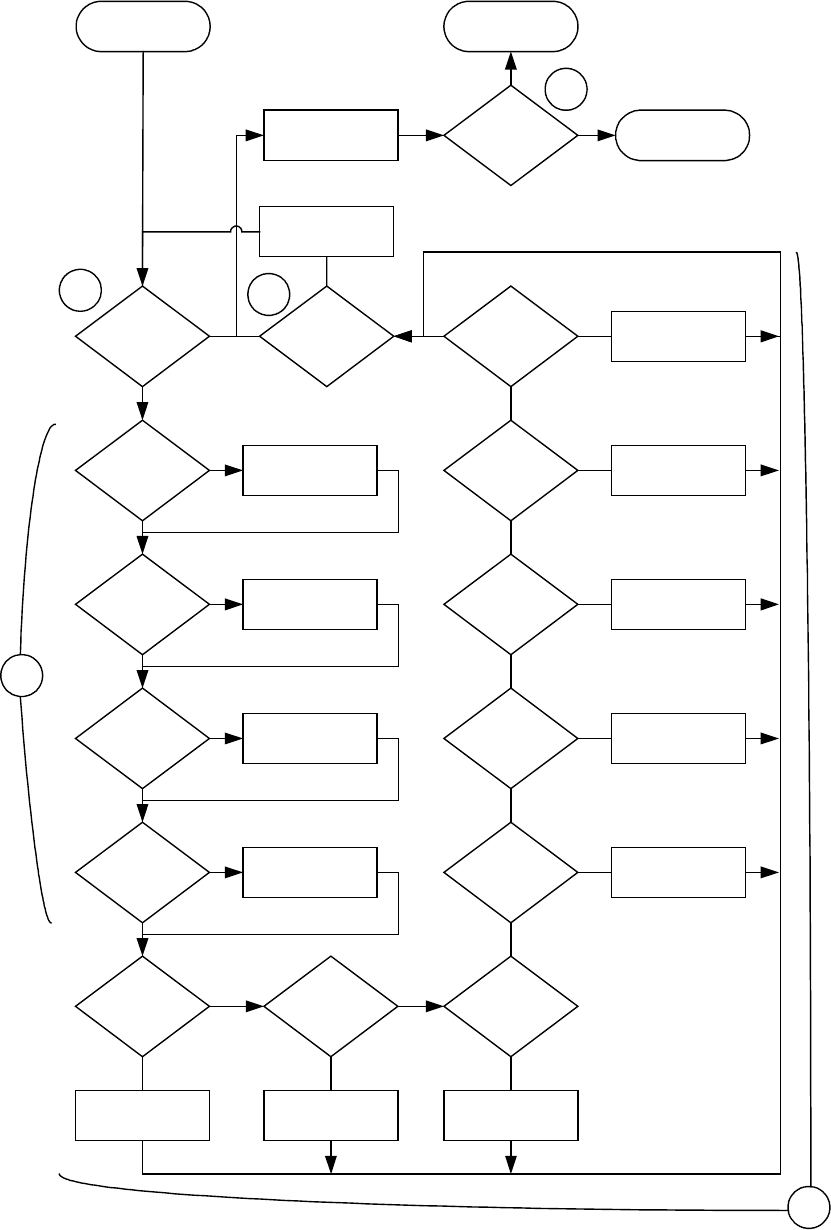
Octopus ATM Defense System
Installation and Operation Guide PageT7
TEST mode software flow diagram.
TEST MODE
TILT
VERIFIED
?
MOTION
TRIGGERED
?
LIGHT
TRANSITION
?
THERMAL
VERIFIED
?
1 BEEP/SEC
2 BEEPS
3 BEEPS
5 BEEPS
DOOR
CLOSED
?
LED CODE
“1101”
NC_2
CLOSED
?
NO_1
OPEN
?
NO_2
OPEN
?
LED CODE
“1100”
ALL_SAFE
SIGNAL
?
MAN_FIRE
OPEN
?
NC_1
CLOSED
?
POWER
LOSS
?
10 MINUTE
TIMEOUT
?
PRESS TO
TEST
?
10 BEEPS DOOR
SECURE
?
STANDBY MODE
ARMED MODE
LED CODE
“1110”
LED CODE
“1100”
LED CODE
“1100”
LED CODE
“1100”
LED CODE
“1100”
LED CODE
“1100”
BLINK RED LED
Y
Y
Y
Y
Y
YYY
Y
Y
Y
Y
Y
N
N
N
N
N
NN
N
N
N
N
N
N
N
Y
T1
T2
T3
T4
T5