3Si Security Systems MCU102A Octopus ATM Defense System User Manual FCC Part 15
3Si Security Systems Inc. Octopus ATM Defense System FCC Part 15
UserManual.wiki
>
3Si Security Systems
>
MCU102A User Manual
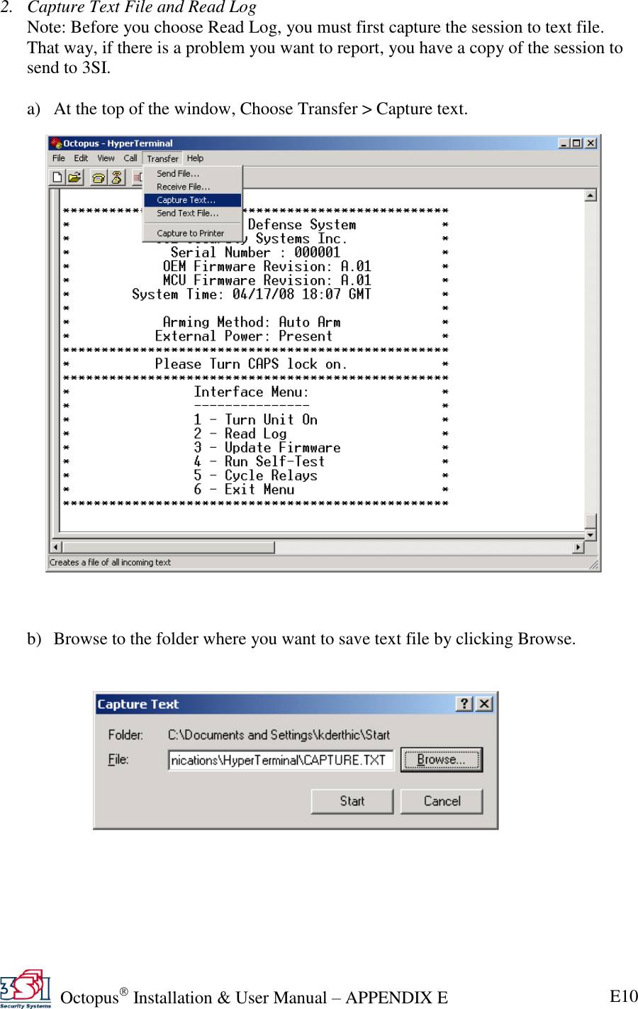
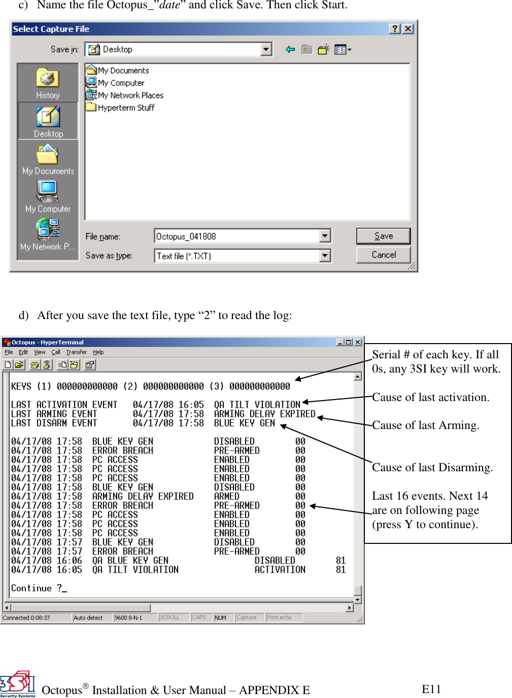
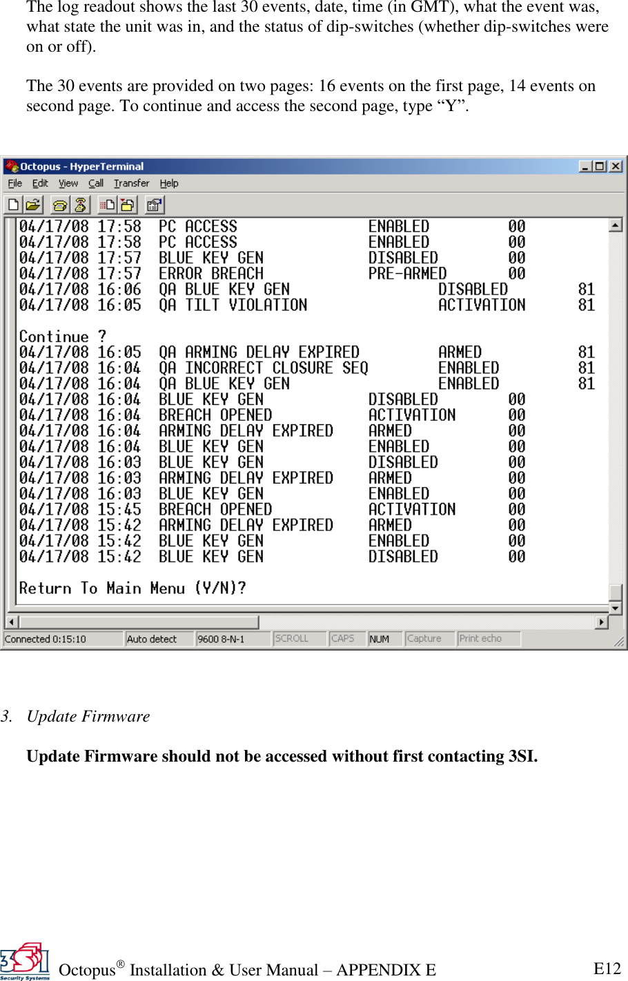
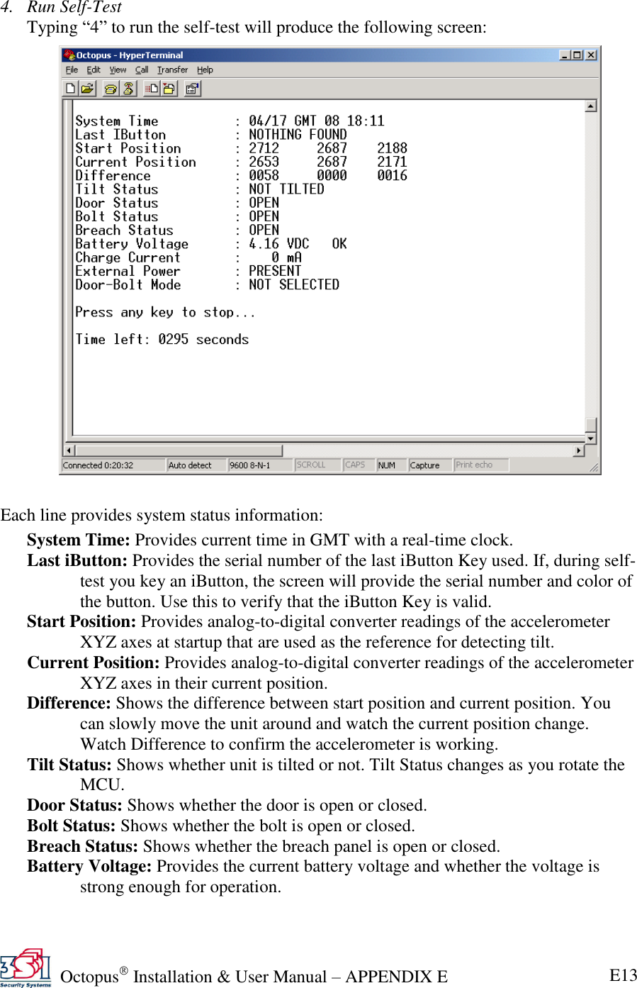
Manual
Navigation menu
Upload a User Manual
Namespaces
Wiki Guide
HTML
PDF
Info
Views
User Manual
Discussion / Help
Navigation