3e Technologies WLAN-MP2 3eTI WLAN mini-PCI Module User Manual Revised
3e Technologies International, Inc. 3eTI WLAN mini-PCI Module Users Manual Revised
Users Manual Revised

Proprietary: This document is issued in strict confidence on condition that it is not copied, reprinted, or disclosed to a third party,
either wholly or in part, without prior written consent of 3e Technologies International, Inc.
3eTI WLAN Mini-PCI Module
CM9
Internal Installation Manual
(FCC ID: QVT-WLAN-MP2)
20000505-001 Revision A
August, 2005
Important Note:
The CM9 module, combined with the proven high-gain antennas, is only for 3e
Technologies International (3eTI) internal use to build Wireless Local Area Network
(WLAN) Equipment. 3eTI does not sell the CM9 WLAN module to either end users or
OEM parties.

20000505-001 Revision A CM9 Internal Installation Manual
Page 2 of 10 Proprietary & Confidential August, 2005
Copyright © 2005 3e Technologies International. All rights reserved. No part of this documentation may be reproduced in any
form or by any means or to make any derivative work (such as translation, transformation, or adaptation) without written
permission from 3e Technologies International.
3e Technologies International reserves the right to revise this documentation and to make changes in content from time to time
without obligation on the part of 3e Technologies International to provide notification of such revision or change.
3e Technologies International provides this documentation without warranty, term or condition of any kind, either implied or
expressed, including, but not limited to, the implied warranties, terms, or conditions of merchantability, satisfactory quality, and
fitness for a particular purpose. 3e Technologies International may make improvements or changes in the product(s) and/or the
program(s) described in this documentation at any time.
If there is any software or removable media described in this documentation, it is furnished under a license agreement included
with the product as a separate document, in the printed documentation, or on the removable media in a readable file such as
license.txt or the like. If you are unable to locate a copy of the license, contact 3e Technologies International and a copy will be
provided to you.
UNITED STATES GOVERNMENT LEGEND
If you are a United States Government agency, then this documentation and the product described herein are provided to you
subject to the following:
All technical data and computer software are commercial in nature and developed solely at private expense. Software
is delivered as “Commercial Computer Software” as defined in DFARS 252.227-7014 (June 1995) or as a “commercial
item” as defined in FAR 2.101(a) and as such is provided with only such rights as are provided in 3e Technologies
International’s standard commercial license for the software. Technical data is provided with limited rights only as
provided in DFAR 252.227-7015 (Nov 1995) or FAR 52.227-14 (June 1987), whichever is applicable. You agree not to
remove or deface any portion of any legend provided on any licensed program or documentation contained in, or
delivered to you in conjunction with, this User Guide.
3e Technologies International and the 3e Technologies International logo are registered trademarks.
Windows is a registered trademark of Microsoft Corporation. Any other company and product name mentioned herein is a
trademark of the respective company with which they are associated.
EXPORT RESTRICTIONS
3e Technologies International products contain encryption and may require U.S. and/or local government authorization prior to
export to another country.
FEDERAL COMMUNICATION COMMISSION STATEMENT
This equipment has been tested and found to comply with the limits for a Class B digital device, pursuant to Part 15 of the FCC
Rules. These limits are designed to provide reasonable protection against harmful interference in a residential installation. This
equipment generates, uses, and can radiate radio frequency energy, and, if not installed and used in accordance with these
instructions, may cause harmful interference to radio communications. However, there is no guarantee that interference will not
occur in a particular installation. If this equipment does cause harmful interference to radio or television reception, which can be
determined by turning the equipment off and on, the user is encouraged to try to correct the interference by one of the following
measures:
• Reorient or relocate the receiving antenna.
• Increase the separation between the equipment and receiver.
• Connect the equipment into an outlet on a circuit different from that to which the receiver is connected.
• Consult the 3eTI for help.
FCC Caution: To assure continued compliance (example - use only shielded interface cables when connecting to computer or
peripheral devices), any changes or modifications not expressly approved by the party responsible for compliance could void the
user's authority to operate this equipment.
This device complies with Part 15 of the FCC Rules. Operation is subject to the following two conditions:
(1) This device may not cause harmful interference, and
(2) This device must accept any interference received, including interference that may cause undesired operation.

CM9 Installation Manual ########-### Revision A
PRINTED COPY UNCONTROLLED UNLESS PRINTED ON IVORY PAPER – VERIFY LATEST REVISION ONLINE.
Revision 00.01.00 Proprietary Page 3 of 10
IMPORTANT NOTES
RF APPLICATION
This FCC ID (QVT-WLAN-MP2) for the combination of the CM9 WLAN module and high gain antennas is restricted to the
outdoor application only. It is only used for 3eTI WLAN outdoor equipment application and the module cannot be sold to end-
users or OEM parties directly. It has to always meet the conditions below:
1. The antenna model 4010 or equipment of the module should be installed and operated with a minimum distance of one (1)
meter between the radiator and all persons. The other antenna model HG5822G or equipment of the module should also
be installed and operated with minimum distance of one (1) meter between the radiator and all persons.
2. The directional antennas should be separated from other WLAN directional antennas with the similar frequency at a
minimum distance of one (1) meter. The antennas cannot be pointed to the same direction.
As long as the two conditions above are met, further transmitter testing will not be required. However, 3eTI is still responsible
for testing the 3eTI end product for any additional compliance requirements required with this module installed (e.g., FCC part
15 for digital device emissions test).
FCC ID
In the event that these conditions listed above cannot be met (e.g., use of the 5.8GHZ high gain antennas for indoor application),
then the FCC authorization is no longer considered valid and the FCC ID cannot be used on the final product. In these
circumstances, the 3eTI will be responsible for re-evaluating the end product (including the transmitter) and obtaining a separate
FCC authorization.
END PRODUCT LABELING
This transmitter module is authorized only for use in devices where the antenna may be installed such that one (1) meter (refer
to RF Application Note above) may be maintained between the antenna and users (e.g., wireless outdoor access points and
bridges). The final end product must be labeled in a visible area with the following: "Contains FCC ID: QVT-WLAN-MP2".
PROHIBITIONS
The end user SHALL NOT be provided with any instructions on how to remove or install the CM9 device.

20000505-001 Revision A CM9 Internal Installation Manual
Page 4 of 10 Proprietary & Confidential August, 2005
APPROVALS
Prepared By:
Frank Li (Date)
Hardware
Engineering:
Norm Lutz (Date)
Software
Engineering
John Fossaceca (Date)
Vice President of
Engineering
Thurston Brooks (Date)
CHANGE HISTORY
Revision
Release
Doc
Approval
Date
Change Description
A ? 08/18/05 Initial Release.
TABLE OF CONTENTS
1. INTRODUCTION .................................................................................................................. 5
1.1. Features ............................................................................................................................................5
1.2. Basic System Requirements............................................................................................................5
1.3. RF Connection .................................................................................................................................5
2. HARDWARE SPECIFICATION............................................................................................ 5
3. HARDWARE INSTALLATION & ANTENNA INFORMATION............................................. 5
4. FCC LABEL ......................................................................................................................... 6
5. ANTENNA INSTALLATION................................................................................................. 6
6. APPENDIX A - FIGURES..................................................................................................... 7
7. APPENDIX B - TABLES .................................................................................................... 10

CM9 Internal Installation Manual 20000505-001 Revision A
August, 2005 Proprietary & Confidential Page 5 of 10
1. INTRODUCTION
The CM9 Wireless Local Area Network (WLAN) module supports the IEEE 802.11a/b/g specification. It
uses the standard mini-PCI interface as the digital port and a special U.FL connector as the RF port.
The CM9 WLAN mini-PCI Module provides a wireless networking function. The dual-band wireless
802.11a/b/g mini-PCI bus adapter operates seamlessly and simultaneously in both the 2.4GHz and 5GHz
frequency spectrums supporting the 802.11b (2.4GHz, 11Mbps) and the newer, faster 802.11a (5.8GHz,
54Mbps/108Mbps turbo mode) and 802.11g (2.4GHz, 54Mbps) wireless standards. It is the best way to
add wireless capability to an existing wired network, or to add bandwidth to a wireless installation.
To protect wireless connectivity, the dual-band wireless 802.11a/b/g mini-PCI bus adapter can encrypt all
wireless transmissions through 64/128/152-bit WEP data encryption. Dynamic Frequency Selection (DFS)
puts the network on the cleanest channel in a given location.
1.1. Features
• High-Speed data transfer rate up to 108Mbps
• 64-bit and 128-bit WEP Encryption
• MAC Address filtering
• Web-Based Network Manager/Telnet for Configuring and Managing Access Points
• SNMP MIB I and MIB II supported
• Capable of acting as a DHCP Server
• Remote Management supported
• Firmware Upgrade via WEB/TFTP
• IEEE802.1x/RADIUS Client (EAP-MD5/TLS/TTLS) Support
1.2. Basic System Requirements
• A computer system that supports the mini- PCI platform and contains:
• 32MB of memory, or greater
• 200MHz processor, or higher
1.3. RF Connection
The CM9 WLAN module uses 50 ohm impedance U.FL connectors with maximum RF power of 18dbm. It
has two RF connectors for the two RF ports (primary and secondary). The two RF ports provided an
antenna diversity feature such that only the port with the best receiving signal quality will be used
dynamically. The two ports support both 802.11b and 802.11g in the 2.4GHZ band, and 802.11a in the
5.8GHZ band with a software switch. See Figure A for details.
2. HARDWARE SPECIFICATION
Table A lists the hardware specification for the CM9 Wireless Local Area Network (WLAN) module.
3. HARDWARE INSTALLATION & ANTENNA INFORMATION
The FCC ID for the CM9 module when combined with proven high gain antennas shall be used only for the
3eTI outdoor WLAN access point or bridge applications. The module is not allowed to be sold to any retail
party or to any OEM party. Due to FCC frequency restrictions and to the requirement of the high gain
antennas for indoor and outdoor applications, the 5.15GHZ to 5.25GHZ indoor frequency band is disabled
in 3eTI outdoor products.
Figure C shows an example of the outdoor bridge 3e-523. Figure D is the open case view of the 3e-523 :
The 3e-523 Processor PCBA loaded with the CM9 module is mounted in the outdoor enclosure.

20000505-001 Revision A CM9 Internal Installation Manual
Page 6 of 10 Proprietary & Confidential August, 2005
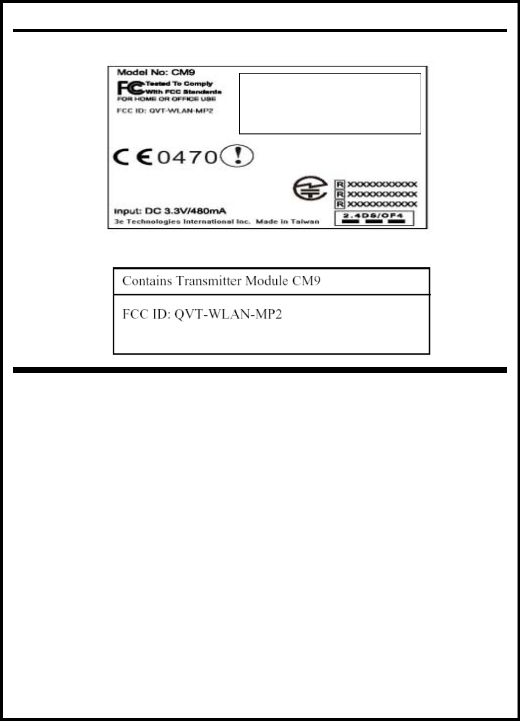
4. FCC LABEL
The CM9 Module must be labeled with its FCC ID (see Figure F). If the FCC ID label shown in Figure F is
not visible when the module is installed inside another (external) device, the external device must also
display a label referring to the enclosed module. The exterior label can be “Contains Transmitter Module
FCC ID:QVT-WLAN-MP2” or similar wording (see Figure G).
5. ANTENNA INSTALLATION
The high gain antennas must be installed outdoors on rooftops, towers, or poles in compliance
with FCC rules. 3eTI enforces the requirement that its products must have professional installation due
to the technical difficulty level during installation for all products that use standard polarity RF connectors.
This professional installation requirement is written into the User Manual and sales agreement for 3eTI
products. The following text provides an example of the requirement from the 3e-525A-2 Users Manual
(Document 29000154-001 Revision A Page 11).
FCC Regulations require that the 3e-525A-2 be professionally installed by an
installer certified by the National Association of Radio and Telecommunications
Engineers or equivalent institution.
Only the following antenna types can be used:
• Antenna 1: Vendor: NEARSON, Model: 4010 (use on the 2400-2483.5 MHz band only).
ALERT!: The module antennae should be installed and operated with minimum distance of one
(1) meter - 100 cm - between the radiator and all persons.
• Antenna 2: Vendor: HyperGain, Model: HG5822G (use on the 5725-5826 MHz band only).
ALERT!: The module antennae should be installed and operated with minimum distance of one
(1) meter - 100 cm - between the radiator and all persons.

CM9 Internal Installation Manual 20000505-001 Revision A
August, 2005 Proprietary & Confidential Page 7 of 10
6. APPENDIX A - FIGURES
Figure A. Front View of the CM9 WLAN Module
Figure B. Rear View of the CM9 WLAN Module
U.FL connector for the
primary antenna port
U.FL connector for the
secondary antenna port

20000505-001 Revision A CM9 Internal Installation Manual
Page 8 of 10 Proprietary & Confidential August, 2005
Figure C. Internal View - CM9 Card Mounted on the 3e-523 Processor PCBA
Figure D. 3e-523 Open Case View
Figure E. 3e-523 Outside View
Reverse Polarity SMA
connector for the RF ports
CM9 Internal Installation Manual 20000505-001 Revision A
August, 2005 Proprietary & Confidential Page 9 of 10
Figure F. CM9 Module FCC ID Label
Figure G. External Device CM9 Module FCC ID Citation Label
This device complies with Part 15 of the FCC Rules
.
Operation is subject to the following two conditions: (1
)
This device may not cause harmful interference, and (2
)
this device must accept any interference received
,
including interference that may cause undesire
d
operation.

20000505-001 Revision A CM9 Internal Installation Manual
Page 10 of 10 Proprietary & Confidential August, 2005
7. APPENDIX B - TABLES
Item Key specifications
Frequency range U-NII: 5.725 ~ 5.825Ghz
2.400 – 2.483GHz
Modulation
technique
802.11b/g
DSSS (DBPSK, DQPSK, CCK)
OFDM for data rate > 20 Mbps
802.11a
OFDM(BPSK,QPSK, 16-QAM, 64-QAM)
Channels support 802.11b/g
US/Canada: 11 (1 ~ 11)
802.11a
1). US/Canada:4 non-overlapping channels (5.725 ~ 5.825GHz)
Operation voltage 3.3V +/- 5%
Maximum Output
Transmit Power 802.11a 802.11b 802.11g
20.27 dBm 22.72 dBm 22.91 dBm
Power
consumption 802.11a 802.11b 802.11g
Continuous Tx 490~510mA @18dBm 570~590mA @18dBm 610~640mA@18dBm
Continuous Rx 340~350mA 360~380mA 420~440mA
FTP Tx 420~440mA 510~530mA 530~545mA
FTP Rx 400~420mA 470~485mA 490~510mA
Standby mode 360~380mA 440~450mA 450~470mA
Power saving mode 50mA 50mA 50mA
RF Kill 40mA 40mA 40mA
Operation
distance
802.11a
Outdoor: 40m@72Mbps,85m@54Mbps,250m@48Mbps,310m@36Mbps
Indoor:20m@72Mbps,25m@54Mbps,35m@48Mbps,40m@36Mbps
802.11b
Outdoor:300m@11Mbps,465m@5.5Mbps,500m@2Mbps,515m@1Mbps
Indoor: 60m@11Mbps,70m@5.5Mbps,83m@2Mbps,85m@1Mbps
802.11g
Outdoor: 82m@54Mbps,100m@48Mbps,300m@36Mbps
Indoor:20m@54Mbps,25m@48Mbps,35m@36Mbps
Operation System
supported
Windows 98SE, ME, 2K, XP
Security 64-bit,128-bit, 152-bit WEP Encryption
802.1x Authentication
AES-CCM & TKIP Encryption
Operation mode
Infrastructure & Ad-hoc mode
Transfer data rate 802.11b/g
11, 5.5, 2, 1 Mbps, auto-fallback, up to 54 Mbps
802.11a (Normal mode)
54, 48, 36, 24, 18, 12, 9, 6Mbps, auto-fallback
802.11a (Turbo mode)
108,96,72,48,36,24,18,12 Mbps, auto-fallback
Operation
temperature
0o ~ 70o C
Storage
temperature
-20o ~ 80o C
Wi-Fi Alliance
WECA Compliant
WHQL Microsoft 2K, XP Complaint
FAA S/W audio On/Off support
Media access
protocol
CSMA/CA with ACK architecture 32-bit MAC