4IPNET 150001 Enterprise Access Point/ Wireless Hotspot Gateway/ Cluster Access Point User Manual 4ipnet EAP706 Handbook EN
4IPNET, INC. Enterprise Access Point/ Wireless Hotspot Gateway/ Cluster Access Point 4ipnet EAP706 Handbook EN
4IPNET >
Contents
- 1. EAP706_User manual
- 2. EAP705_User manual
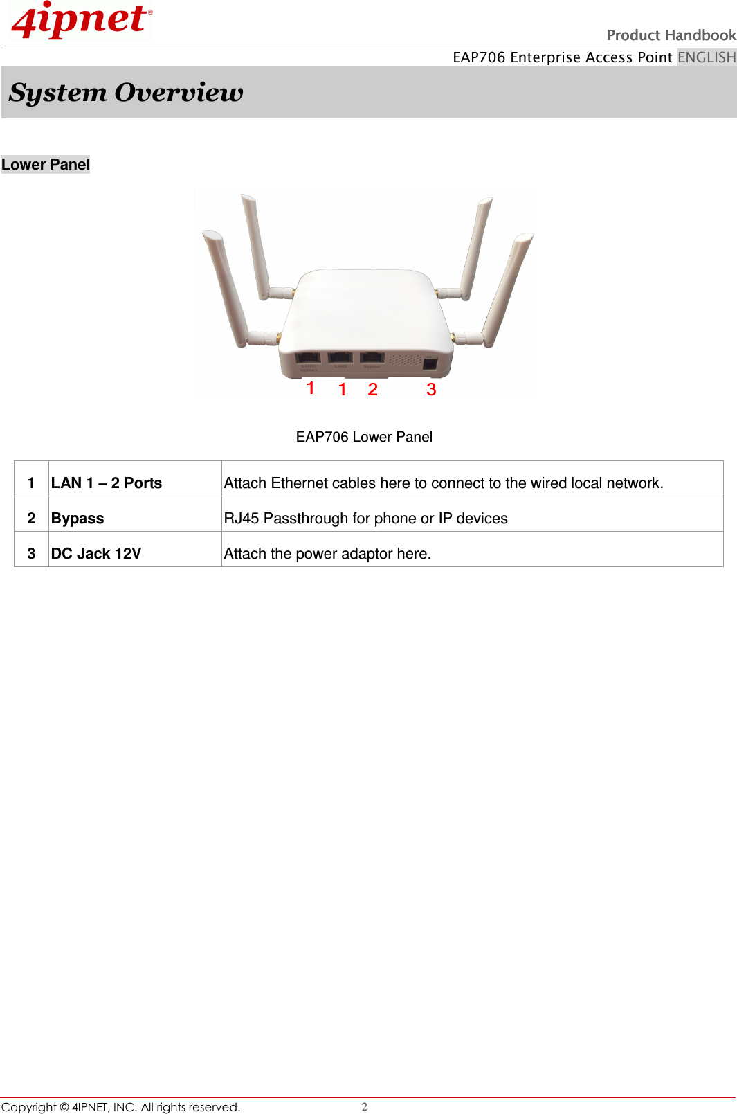
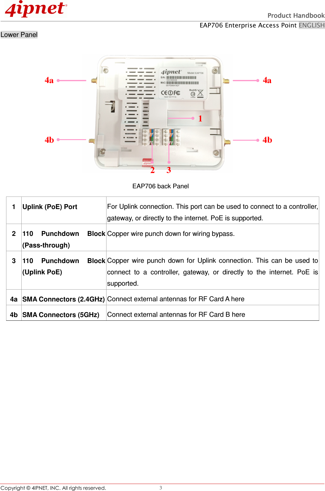
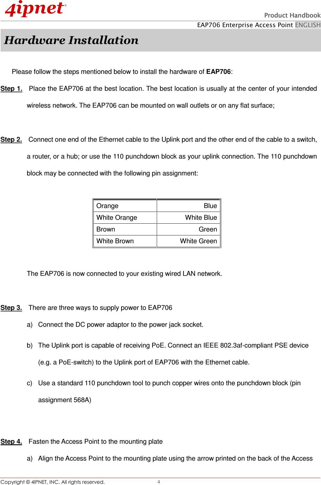
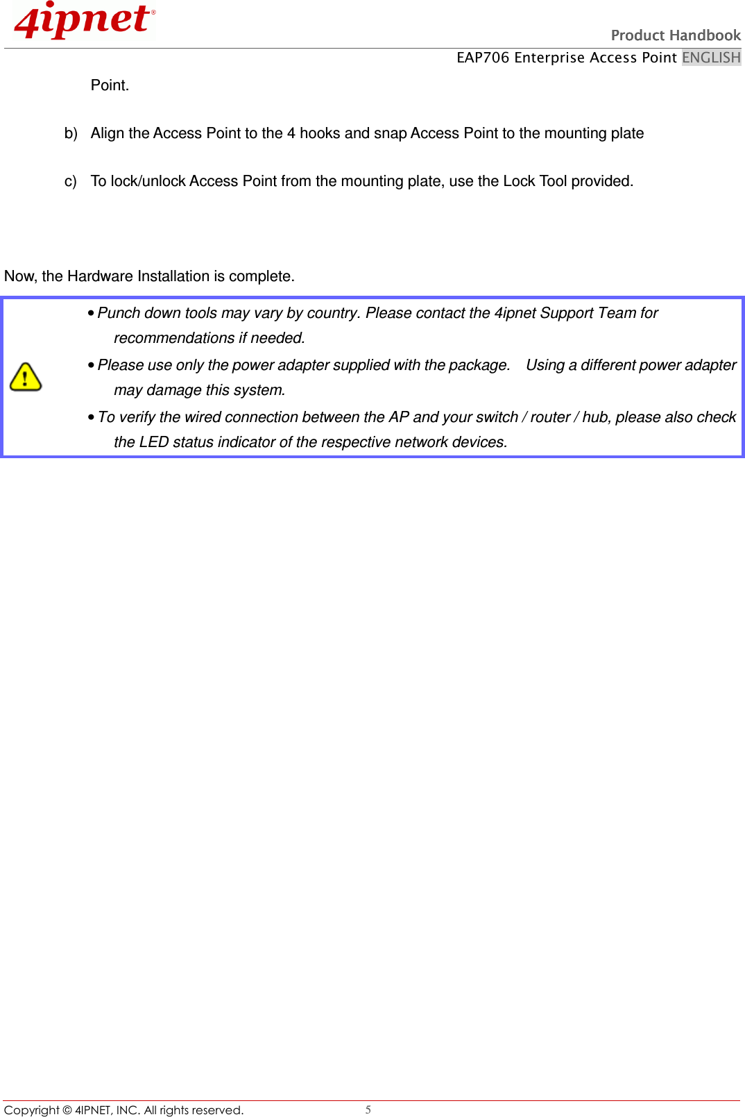
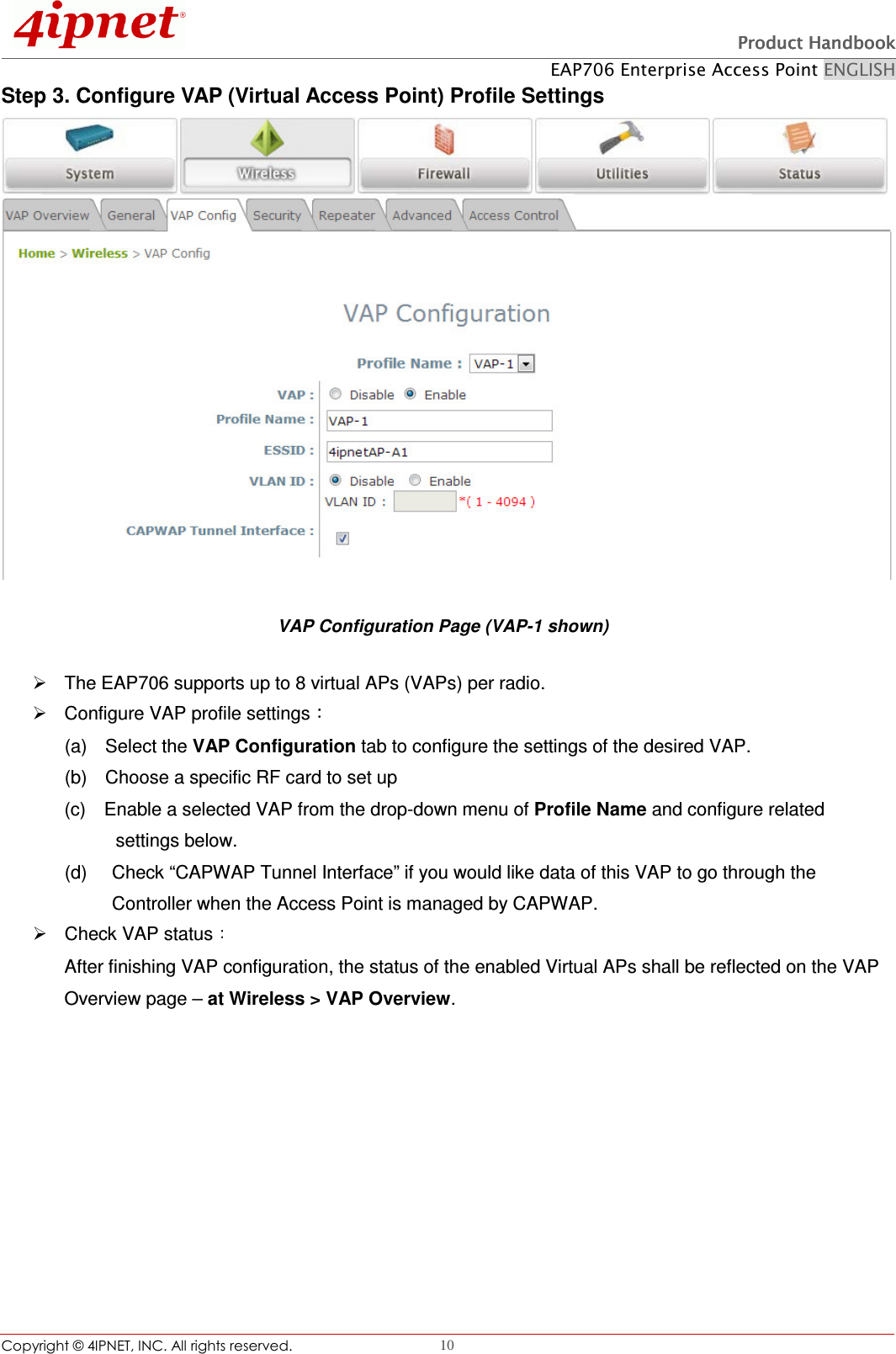
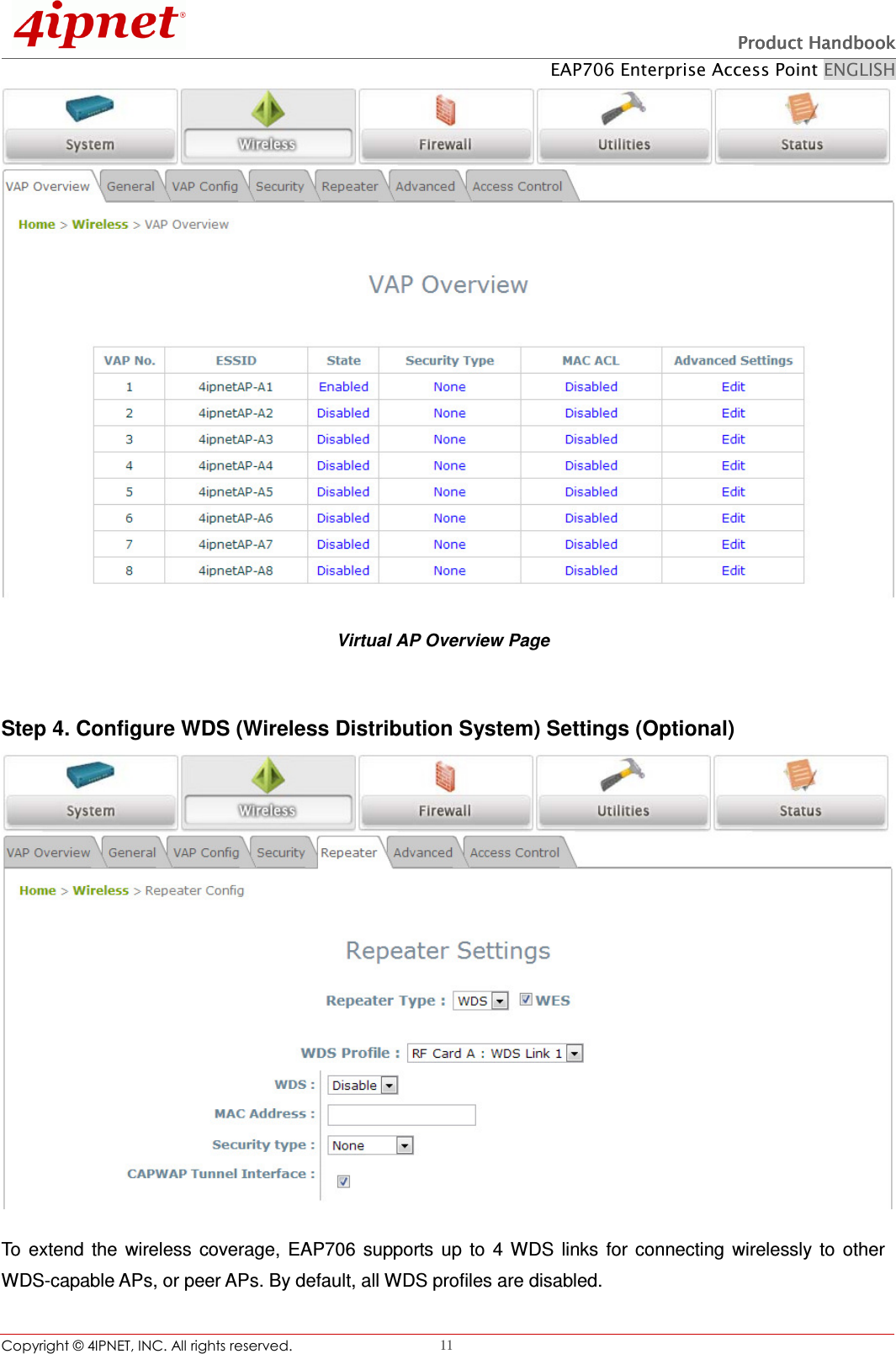
EAP706_User manual