4IPNET 150001 Enterprise Access Point/ Wireless Hotspot Gateway/ Cluster Access Point User Manual 4ipnet EAP706 Handbook EN
4IPNET, INC. Enterprise Access Point/ Wireless Hotspot Gateway/ Cluster Access Point 4ipnet EAP706 Handbook EN
4IPNET >
Contents
- 1. EAP706_User manual
- 2. EAP705_User manual
EAP706_User manual

EAP706 V1.0
0
Enterp
rise Access Point
Product Handbook

Product Handbook
Product HandbookProduct Handbook
Product Handbook
EAP706 Enterprise Access Point ENGLISH
Copyright © 4IPNET, INC. All rights reserved. i
Copyright Notice
This document is protected by USA copyright laws and other laws. Besides, the
document is the property of 4IPNET, INC. You may not copy, reproduce, distribute,
publish, display, perform, or modify any part of this publication in any form or by any
means without prior written permission from 4IPNET, INC. You may not alter or remove any
copyright or other notice from copies of the content. All other brand and product names
are claimed or registered marks of their respective companies or organizations.
All rights reserved.
To download up-to-date version, please visit www.4ipnet.com.

Product Handbook
Product HandbookProduct Handbook
Product Handbook
EAP706 Enterprise Access Point ENGLISH
Copyright © 4IPNET, INC. All rights reserved. ii
FCC CAUTION
This equipment has been tested and proven to comply with the limits for a class B digital device,
pursuant to part 15 of the FCC Rules. These limits are designed to provide reasonable protection
against harmful interference in a residential installation. This equipment generates uses and can
radiate radio frequency energy and, if not installed and used in accordance with the instructions, may
cause harmful interference to radio communications. However, there is no guarantee that
interference will not occur in a particular installation. If this equipment does cause harmful
interference to radio or television reception, which can be determined by turning the equipment off
and on, the user is encouraged to try to correct the interference by one or more of the following
measures:
---Reorient or relocate the receiving antenna.
---Increase the separation between the equipment and receiver.
---Connect the equipment into an outlet on a circuit different from that to which the receiver is
connected.
---Consult the dealer or an experienced radio/TV technician for help.
The device contains a low power transmitter which will send out Radio Frequency (RF) signal when
transmitting. This equipment complies with FCC RF radiation exposure limits set forth for an uncontrolled
environment. This equipment should be installed and operated with a minimum distance of 20 centimeters
between the radiator and your body.
This device complies with Part 15 of the FCC Rules. Operation is subject to the following two conditions:
(1) This device may not cause harmful interference, and
(2) This device must accept any interference received, including interference that may cause undesired
operation.
Any changes or modifications not expressly approved by the party responsible for compliance could
void the user's authority to operate this equipment.
This transmitter must not be co-located or operating in conjunction with any other antenna or
transmitter.

Product Handbook
Product HandbookProduct Handbook
Product Handbook
EAP706 Enterprise Access Point ENGLISH
Copyright © 4IPNET, INC. All rights reserved. iii
CE CAUTION
Declaration of Conformity with Regard to the 1999/5/EC (R&TTE Directive) for
European Community, Switzerland, Norway, Iceland, and Liechtenstein
Model: EAP706
For 2.4 GHz radios, the device has been tested and passed the requirements of the following standards, and
hence fulfills the EMC and safety requirements of R&TTE Directive within the CE marking requirement.
• Radio: EN 300.328
:
• EMC: EN 301.489-1, EN 301.489-17,
• EMC: EN 55022
Class B, EN 55024
:
+ A1 + A2
including the followings:
EN 61000-3-2, EN 61000-3-3.
EN 61000-4-2, EN 61000-4-3, EN 61000-4-4,
EN 61000-4-5, EN 61000-4-6, EN 61000-4-11
• Safety: EN 60950-1 + A11,
Caution:
This declaration is only valid for configurations (combinations of software, firmware, and hardware)
provided and supported by 4ipnet Inc. The use of software or firmware not provided and supported by
4ipnet Inc. may result in the equipment no longer being compliant with the regulatory requirements.
European standards dictate maximum radiated transmit power of 100mW EIRP and frequency range
2.400-2.4835 GHz. This equipment is intended to be used in all EU and EFTA countries. Outdoor use may be
restricted to certain frequencies and/or may require a license for operation. Contact your local regulatory
authority for compliance.
Taiwan NCC Statement
NCC :
Product Handbook
Product HandbookProduct Handbook
Product Handbook
EAP706 Enterprise Access Point ENGLISH
Copyright © 4IPNET, INC. All rights reserved. 1
Preface Package Contents
The 4ipnet EAP706 Wall Jack Access Point is an
on-the-wall as well as a ceiling-mounted dual radio
Wi-Fi IEEE 802.11b/g/n + a/n/ac 2 X 2 MIMO
access point, designed to blend into a working or
a living environment practically and elegantly with
its simplistic yet sleek design.
The compact EAP706 in a small form factor lays
snug in a standard wall outlet box. Its side panel
features LED status indicators and two RJ45 ports.
It has the interfaces to serve both wireless and
wired LAN access. The RJ45 pass-through port
allows phone or IP-based devices to pass through
EAP706 without the need for additional outlets.
When coupled with the 4ipnet WHG series
Controller, the EAP706 supports Tunnel-based AP
Management, and comes with all standards
demanded by enterprise applications, including
business-grade security (802.1X, WPA and WPA2),
and multiple ESSIDs with VLAN tags to separate
the traffics of different departments. A centralized
WLAN management allows enterprises and
organizations to support a wide array of value
added applications, such as load balancing,
bandwidth control, and access control. The
patent-pending 4ipWES (Press-n-Connect)
technology bridges multiple EAP706s at the touch
of a button, which enables a quick and automatic
WDS Easy Setup by pressing the WES button on
EAP706. Extending wireless network coverage is a
breeze, be it across conference rooms or along
hallways.
EAP706’s high performance, security and optimal
invisibility make it a perfect choice of wireless
connectivity for your business.
1. 4ipnet EAP706 x 1
2. Quick Installation Guide (QIG) x 1
3. Power Adapter (DC 12V) x 1 (Optional)
4. Mounting Screws x 2
5. Mounting Panel x 1
6. Mounting Plate Lock Tool x 1
7. Detachable Antenna x 4
It is recommended to keep the original
packing material for possible future shipment
when repair or maintenance is required. Any
returned product should be packed in its
original packaging to prevent damage during
delivery.
Product Handbook
Product HandbookProduct Handbook
Product Handbook
EAP706 Enterprise Access Point ENGLISH
Copyright © 4IPNET, INC. All rights reserved.
2
System Overview
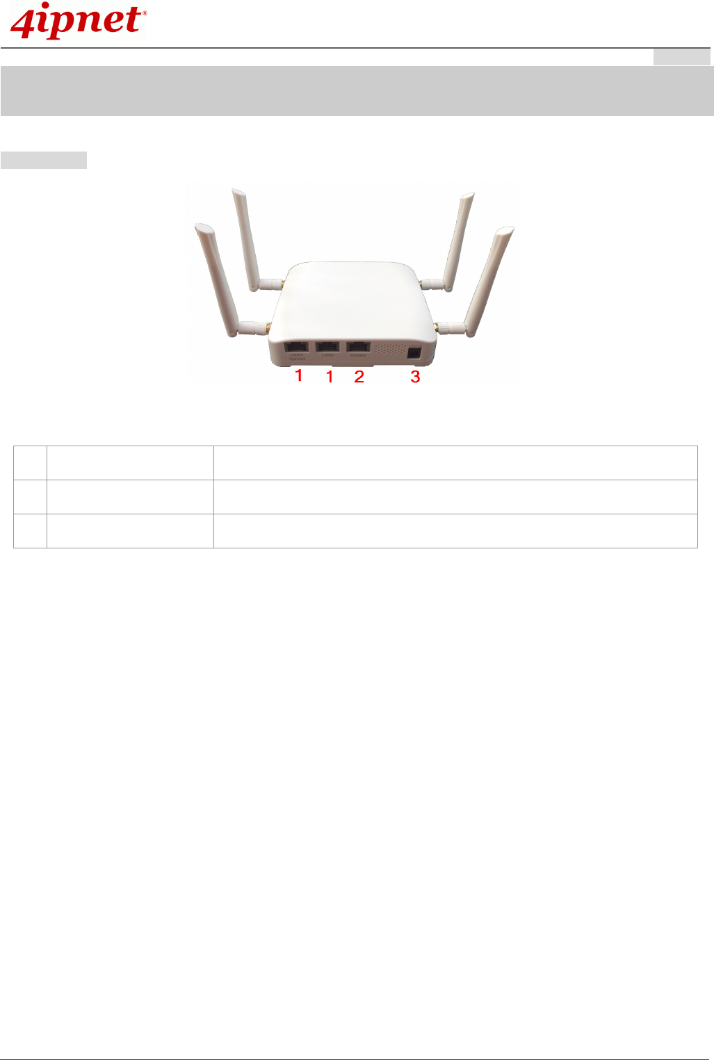
Lower Panel
EAP706 Lower Panel
1
LAN 1 – 2 Ports Attach Ethernet cables here to connect to the wired local network.
2
Bypass RJ45 Passthrough for phone or IP devices
3
DC Jack 12V Attach the power adaptor here.
Product Handbook
Product HandbookProduct Handbook
Product Handbook
EAP706 Enterprise Access Point ENGLISH
Copyright © 4IPNET, INC. All rights reserved.
3
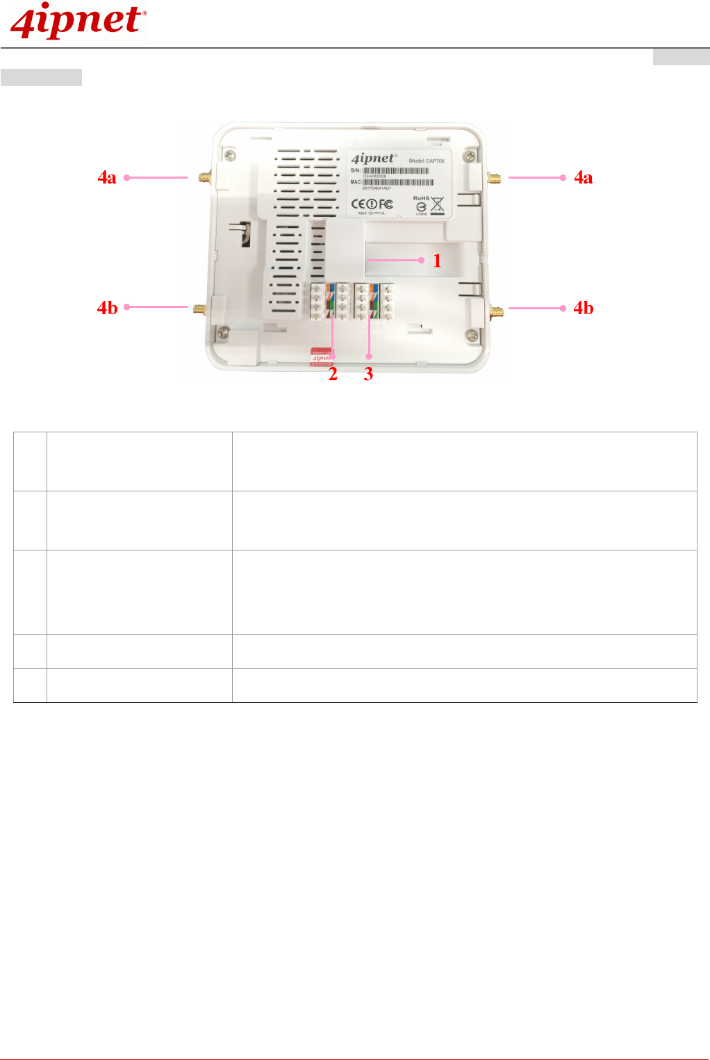
Lower Panel
EAP706 back Panel
1
Uplink (PoE) Port
For Uplink connection. This port can be used to connect to a controller,
gateway, or directly to the internet. PoE is supported.
2
110 Punchdown Block
(Pass-through)
Copper wire punch down for wiring bypass.
3
110 Punchdown Block
(Uplink PoE)
Copper wire punch down f
or Uplink connection. This can be used to
connect to a controller, gateway, or directly to the internet. PoE is
supported.
4a
SMA Connectors (2.4GHz)
Connect external antennas for RF Card A here
4b
SMA Connectors (5GHz) Connect external antennas for RF Card B here
Product Handbook
Product HandbookProduct Handbook
Product Handbook
EAP706 Enterprise Access Point ENGLISH
Copyright © 4IPNET, INC. All rights reserved.
4
Hardware Installation
Please follow the steps mentioned below to install the hardware of EAP706:
Step 1. Place the EAP706 at the best location. The best location is usually at the center of your intended
wireless network. The EAP706 can be mounted on wall outlets or on any flat surface;
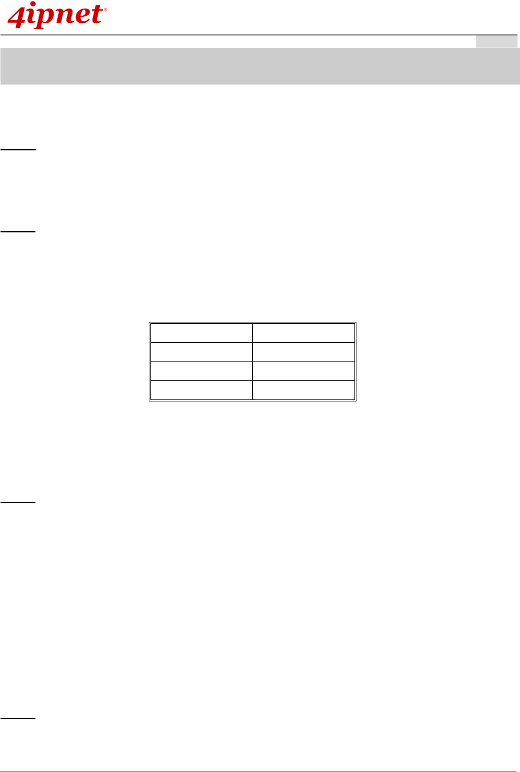
Step 2. Connect one end of the Ethernet cable to the Uplink port and the other end of the cable to a switch,
a router, or a hub; or use the 110 punchdown block as your uplink connection. The 110 punchdown
block may be connected with the following pin assignment:
Orange Blue
White Orange White Blue
Brown Green
White Brown White Green
The EAP706 is now connected to your existing wired LAN network.
Step 3. There are three ways to supply power to EAP706
a) Connect the DC power adaptor to the power jack socket.
b) The Uplink port is capable of receiving PoE. Connect an IEEE 802.3af-compliant PSE device
(e.g. a PoE-switch) to the Uplink port of EAP706 with the Ethernet cable.
c) Use a standard 110 punchdown tool to punch copper wires onto the punchdown block (pin
assignment 568A)
Step 4. Fasten the Access Point to the mounting plate
a) Align the Access Point to the mounting plate using the arrow printed on the back of the Access
Product Handbook
Product HandbookProduct Handbook
Product Handbook
EAP706 Enterprise Access Point ENGLISH
Copyright © 4IPNET, INC. All rights reserved.
5
Point.
b) Align the Access Point to the 4 hooks and snap Access Point to the mounting plate
c) To lock/unlock Access Point from the mounting plate, use the Lock Tool provided.
Now, the Hardware Installation is complete.
• Punch down tools may vary by country. Please contact the 4ipnet Support Team for
recommendations if needed.
• Please use only the power adapter supplied with the package. Using a different power adapter
may damage this system.
• To verify the wired connection between the AP and your switch / router / hub, please also check
the LED status indicator of the respective network devices.

Product Handbook
Product HandbookProduct Handbook
Product Handbook
EAP706 Enterprise Access Point ENGLISH
Copyright © 4IPNET, INC. All rights reserved.
6
Getting Started
4ipnet EAP706 supports web-based configuration. When hardware installation is complete, EAP706 can be
configured through a PC by using a web browser such as Mozilla Firefox 2.0 or Internet Explorer version 6.0
and above.
The default values of LAN IP address and subnet mask of EAP706 are:
IP Address: 192.168.1.1
Subnet Mask: 255.255.255.0
Steps:
1. To access the Web Management Interface, connect the administrator PC to the LAN port of EAP706 via
an Ethernet cable. Then, set a static IP address on the same subnet mask as EAP706 in TCP/IP of your
PC, such as the following example:
IP Address: 192.168.1.100
Subnet Mask: 255.255.255.0
2. Launch the web browser on your PC by entering the IP address of EAP706 (http://192.168.1.1) at the
address field, and then press Enter.
3. The following Admin Login Page will appear. Enter “admin” for both the Username and Password fields,
and then click Login.
Administrator Login Page
Product Handbook
Product HandbookProduct Handbook
Product Handbook
EAP706 Enterprise Access Point ENGLISH
Copyright © 4IPNET, INC. All rights reserved.
7
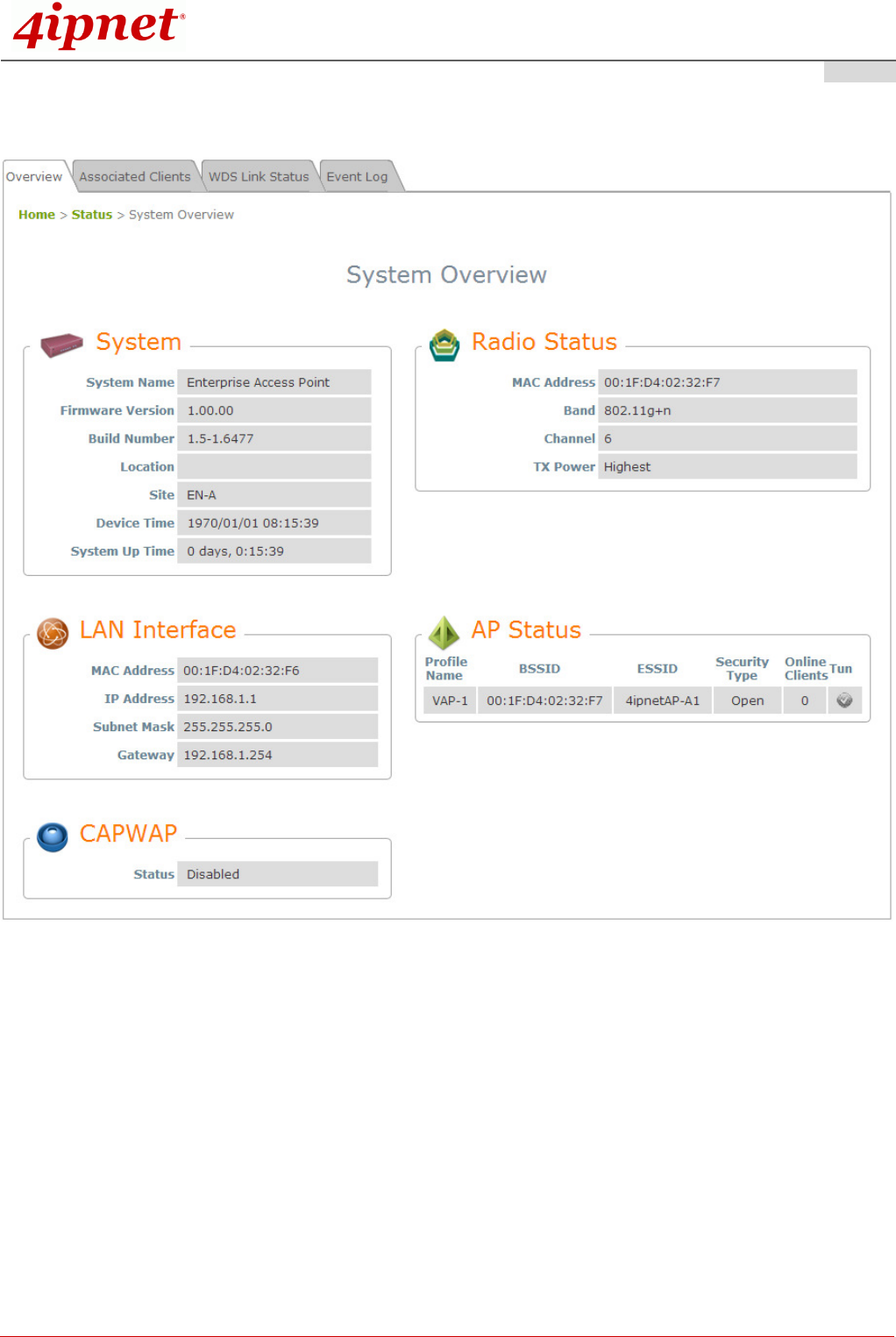
4. After a successful login to EAP706, a System Overview page of the Web Management Interface will
appear, as depicted below. The Radio Status and AP Status will be shown.
The Web Management Interface - System Overview Page
5. To logout, simply click on the Logout button at the upper-right corner of the interface to return to the
Administrator Login Page. Click OK to logout.
Product Handbook
Product HandbookProduct Handbook
Product Handbook
EAP706 Enterprise Access Point ENGLISH
Copyright © 4IPNET, INC. All rights reserved.
8
Common Settings
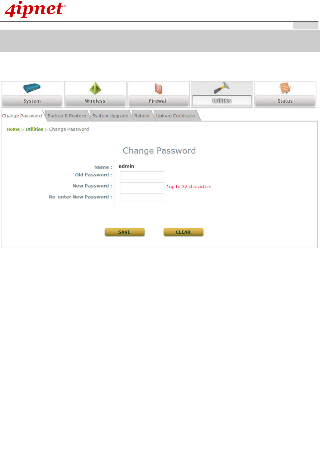
Step 1. Change Administrator’s Password
Change Password Page
Click on the Utilities icon on the main menu, and select the Change Password tab.
Enter the old password and then a new password with a length of up to 32 characters, and retype it in
the Re-enter New Password field.
Click SAVE to save the changes.
Product Handbook
Product HandbookProduct Handbook
Product Handbook
EAP706 Enterprise Access Point ENGLISH
Copyright © 4IPNET, INC. All rights reserved.
9
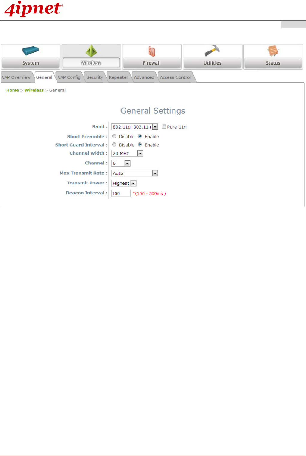
Step 2. Configure General AP (Access Point) Settings
Wireless General Settings Page
Click on the Wireless icon on the main menu, and then select the General tab.
Select the RF card you would like to set up.
Determine the Band and Channel settings:
Select your preferred Band and Channel for you wireless connection. For example, select
802.11g+802.11n for the band and 6 for the channel.
Product Handbook
Product HandbookProduct Handbook
Product Handbook
EAP706 Enterprise Access Point ENGLISH
Copyright © 4IPNET, INC. All rights reserved.
10
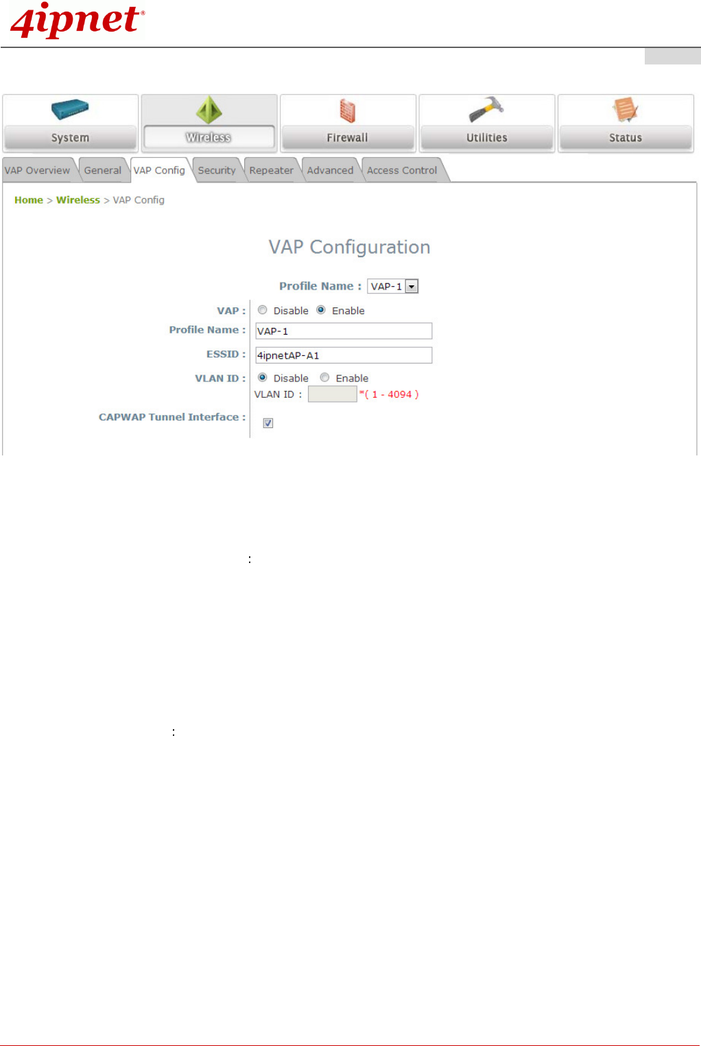
Step 3. Configure VAP (Virtual Access Point) Profile Settings
VAP Configuration Page (VAP-1 shown)
The EAP706 supports up to 8 virtual APs (VAPs) per radio.
Configure VAP profile settings
(a) Select the VAP Configuration tab to configure the settings of the desired VAP.
(b) Choose a specific RF card to set up
(c) Enable a selected VAP from the drop-down menu of Profile Name and configure related
settings below.
(d) Check “CAPWAP Tunnel Interface” if you would like data of this VAP to go through the
Controller when the Access Point is managed by CAPWAP.
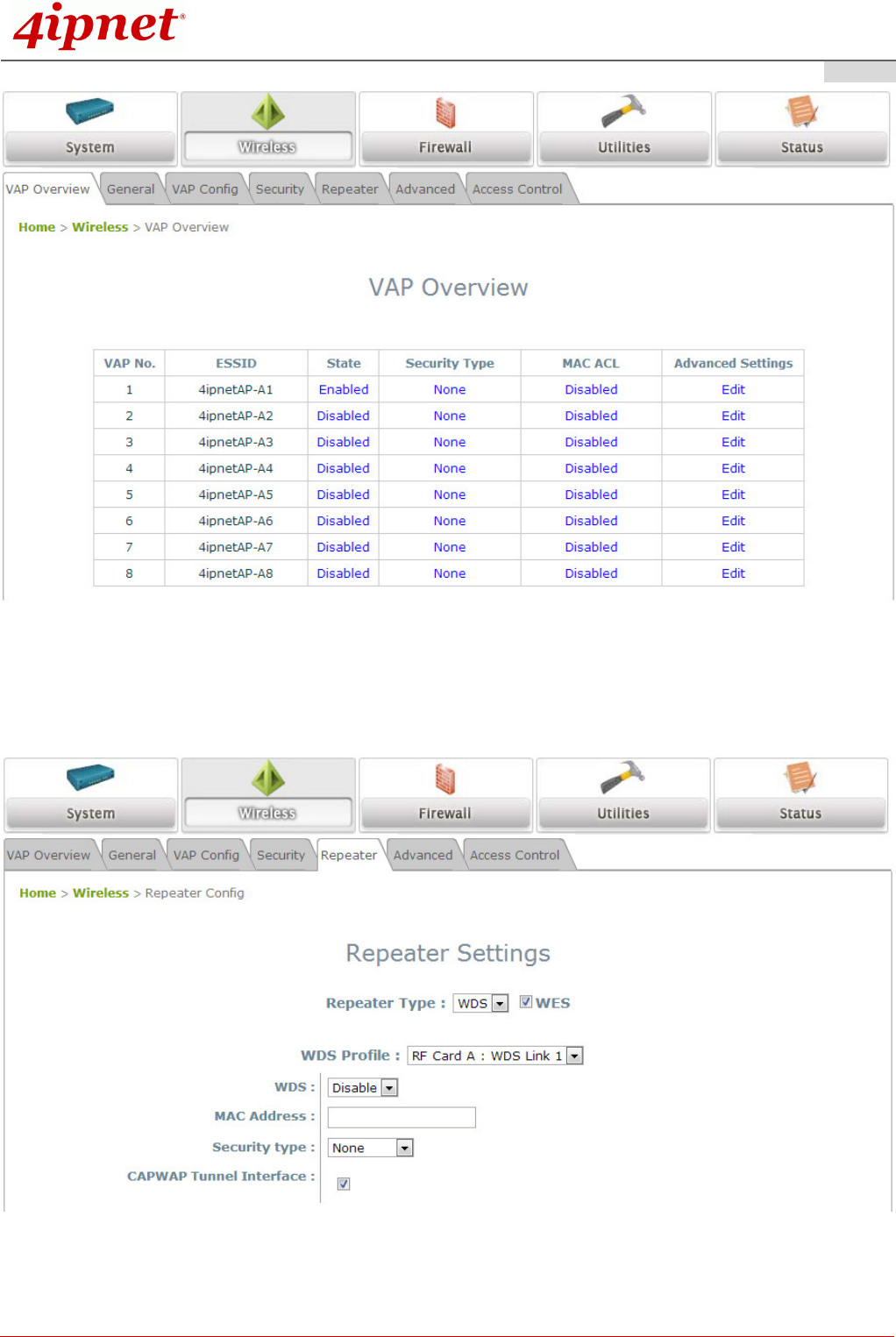
Check VAP status
After finishing VAP configuration, the status of the enabled Virtual APs shall be reflected on the VAP
Overview page – at Wireless > VAP Overview.
Product Handbook
Product HandbookProduct Handbook
Product Handbook
EAP706 Enterprise Access Point ENGLISH
Copyright © 4IPNET, INC. All rights reserved.
11
Virtual AP Overview Page
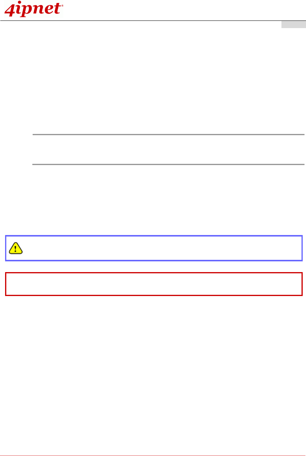
Step 4. Configure WDS (Wireless Distribution System) Settings (Optional)
To extend the wireless coverage, EAP706 supports up to 4 WDS links for connecting wirelessly to other
WDS-capable APs, or peer APs. By default, all WDS profiles are disabled.
Product Handbook
Product HandbookProduct Handbook
Product Handbook
EAP706 Enterprise Access Point ENGLISH
Copyright © 4IPNET, INC. All rights reserved.
12
Click on the Wireless button on the main menu.
Select the Repeater tab.
Choose WDS as the Repeater Type.
Choose the desired RF card and WDS profile:
(a) Enable WDS.
(b) Enter the MAC Address (peer AP) and then Click SAVE.
If you are using another EAP706 as the peer AP, simply repeat the above-mentioned steps to configure
another peer AP(s).
Note:
On each and every configuration page, you may click SAVE to save the changes of your configured
settings, but you must reboot the system for the changes to take effect. After clicking SAVE, the
following message will appear: “Some modifications have been saved and will take effect after
Reboot.”
Congratulations!
Now, 4ipnet EAP706 is installed and configured successfully.
After EAP706's network configuration is completed, please remember to change the IP Address of
your PC Connection Properties back to its original settings in order to ensure that your PC functions
properly in its real network environments.
It is strongly recommended to back up your configuration settings.
For further configuration and information, please refer to the User’s Manual.
P/N: V10020150519