4IPNET 150002 Enterprise Access Point User Manual Model OWL630
4IPNET, INC. Enterprise Access Point Model OWL630
4IPNET >
Contents
- 1. User Manual (for EAP330)
- 2. User Manual (for model-OWL630)
- 3. User Manual - Model EAP330
- 4. User Manual - Model OWL630
User Manual - Model OWL630

OWL630
Enterprise Access Point
Handbook

Handbook
OWL630 Enterprise Access Point ENGLISH
Copyright © 4IPNET, INC. All rights reserved.
i
Copyright Notice
This document is protected by USA copyright laws and other laws. Besides, the
document is the property of 4IPNET, INC. You may not copy, reproduce, distribute,
publish, display, perform, or modify any part of this publication in any form or by any
means without prior written permission from 4IPNET, INC. You may not alter or remove any
copyright or other notice from copies of the content. All other brand and product names
are claimed or registered marks of their respective companies or organizations.
All rights reserved.
To download up-to-date version, please visit www.4ipnet.com.

Handbook
OWL630 Enterprise Access Point ENGLISH
Copyright © 4IPNET, INC. All rights reserved.
ii
FCC CAUTION
This equipment has been tested and found to comply with the limits for a Class B digital device,
pursuant to Part 15 of the FCC Rules. These limits are designed to provide reasonable protection
against harmful interference in a residential installation. This equipment generates, uses and can
radiate radio frequency energy and, if not installed and used in accordance with the instructions, may
cause harmful interference to radio communications. However, there is no guarantee that
interference will not occur in a particular installation. If this equipment does cause harmful
interference to radio or television reception, which can be determined by turning the equipment off
and on, the user is encouraged to try to correct the interference by one or more of the following
measures:
Reorient or relocate the receiving antenna.
Increase the separation between the equipment and receiver.
Connect the equipment into an outlet on a circuit different from that to which the receiver is
connected.
Consult the dealer or an experienced radio/TV technician for help.
Any changes or modifications not expressly approved by the party responsible for compliance could void the
user's authority to operate this equipment.
This device complies with Part 15 of the FCC Rules. Operation is subject to the following two conditions: (1)
This device may not cause harmful interference, and (2) this device must accept any interference received,
including interference that may cause undesired operation.
This device and its antenna(s) must not be co-located or operating in conjunction with any other antenna or
transmitter.
For product available in the USA/Canada market, only channel 1~11 can be operated. Selection of other
channels is not possible.
This device is restricted to indoor use when operated in the 5.15 to 5.25 GHz frequency range.
※ FCC requires this product to be used indoors for the frequency range 5.15 to 5.25 GHz to reduce the
potential for harmful interference to co-channel Mobile Satellite systems.
IMPORTANT NOTE:
FCC Radiation Exposure Statement:
This equipment complies with FCC radiation exposure limits set forth for an uncontrolled environment. This
equipment should be installed and operated with minimum distance 20cm between the radiator & your body.

Handbook
OWL630 Enterprise Access Point ENGLISH
Copyright © 4IPNET, INC. All rights reserved.
iii
CE CAUTION
Declaration of Conformity with Regard to the 1999/5/EC (R&TTE Directive) for
European Community, Switzerland, Norway, Iceland, and Liechtenstein
Model: OWL630
For 2.4 GHz radios, the device has been tested and passed the requirements of the following standards, and
hence fulfills the EMC and safety requirements of R&TTE Directive within the CE marking requirement.
• Radio: EN 300.328:
• Radio: EN 50392
• EMC: EN 301.489-1, EN 301.489-17,
• EMC: EN 55022 Class B, EN 55024:+ A1 + A2 including the followings:
EN 61000-3-2, EN 61000-3-3.
EN 61000-4-2, EN 61000-4-3, EN 61000-4-4,
EN 61000-4-5, EN 61000-4-6, EN 61000-4-11
• Safety: EN 60950-1 + A11,
Caution:
This declaration is only valid for configurations (combinations of software, firmware, and hardware)
provided and supported by 4ipnet Inc. The use of software or firmware not provided and supported by
4ipnet Inc. may result in the equipment no longer being compliant with the regulatory requirements.
European standards dictate maximum radiated transmit power of 100mW EIRP and frequency range
2.400-2.4835 GHz. This equipment is intended to be used in all EU and EFTA countries. Outdoor use
may be restricted to certain frequencies and/or may require a license for operation. Contact your local
regulatory authority for compliance.
Taiwan NCC Statement
根據 NCC 低功率電波輻射性電機管理辦法 規定:
第十二條
經型式認證合格之低功率射頻電機,非經許可,公司、商號或使用者均不得擅自變更頻率、加大功率或
變更原設計之特性及功能。
第十四條
低功率射頻電機之使用不得影響飛航安全及干擾合法通信;經發現有干擾現象時,應立即停用,並改善
至無干擾時方得繼續使用。前項合法通信,指依電信法規定作業之無線電通信。低功率射頻電機須忍受
合法通信或工業、科學及醫療用電波輻射性電機設備之干擾。
在5.25 ~ 5.35 秭赫頻帶內操作之無線資訊傳輸設備,限於室內使用。
減少電磁波影響,請妥適使用

Handbook
OWL630 Enterprise Access Point ENGLISH
Copyright © 4IPNET, INC. All rights reserved.
1
Preface
Package Contents
The OWL630 is a rugged multi-mode, high-end dual
radio 802.11 b/g/n + ac MIMO Access Point (AP),
specifically designed for building municipal or
campus wide wireless networks. There are two
system modes that can be used for dual purposes.
It can be deployed as a traditional multi-wireless
Access Point (AP) or a Relay. The OWL630 access
points make wireless communication fast, secure
and easy.
The die-cast Aluminum sealed OWL630 is rust-free
and IP68 compliant. It is high wind load resilient and
is designed to operate in a wide range of
temperature. Flexible deployment with a variety of
antennas allows OWL630 to easily serve clients
located in different directions as well as for
coverage extension.
This handbook provides instructions for getting
started with the OWL Access Point.
1. 4ipnet OWL630 x 1
2. Handbook x 1
3. Power Sourcing Equipment (PSE) X 1
(Optional)
4. Mounting Kit x 1
5. Ground Cable x 1
6. Waterproof M12 Connector Pack x 1
7. Waterproof RJ45 Connector Pack x 2
It is recommended to keep the original
packing material for possible future shipment
when repair or maintenance is required. Any
returned product should be packed in its
original packaging to prevent damage during
delivery.
Handbook
OWL630 Enterprise Access Point ENGLISH
Copyright © 4IPNET, INC. All rights reserved.
2
System Overview
OWL630
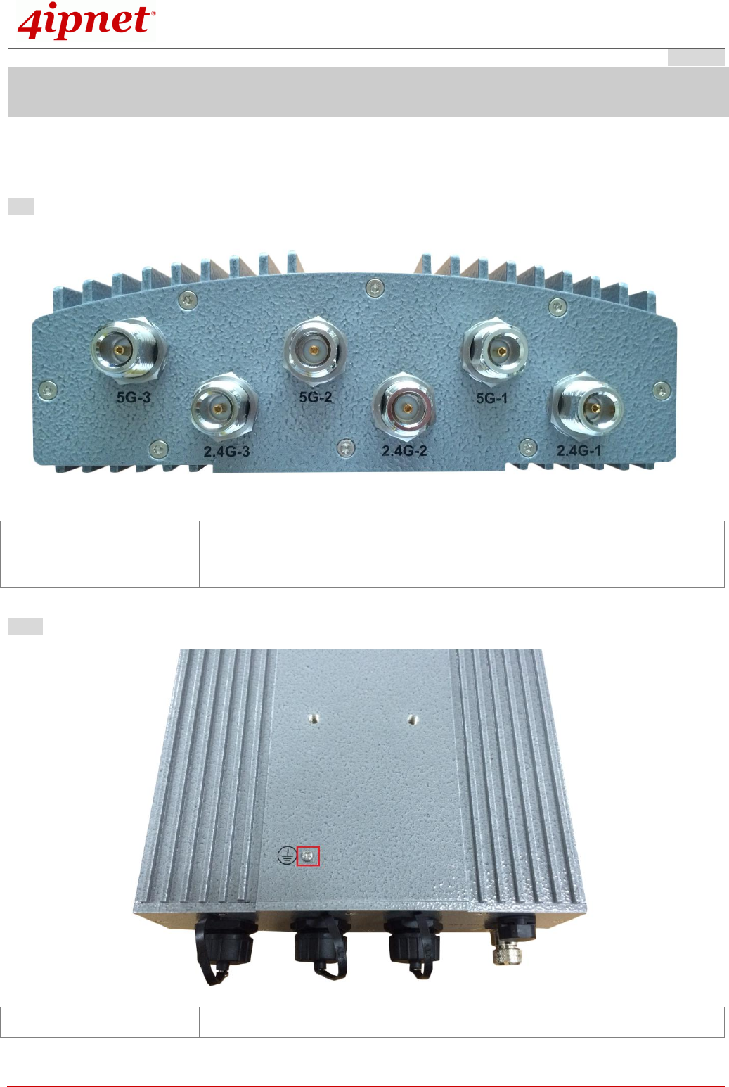
Top
Back
N-type Connector x 4
For connecting to an antenna (RF Card A x 2, RF Card B x 2)
Connector marked –1 is for the primary antenna when the AP is not in 802.11n
or 802.11ac mode. Utilize all connectors for optimized MIMO performance.
Ground Connector
For connecting the ground wire
Handbook
OWL630 Enterprise Access Point ENGLISH
Copyright © 4IPNET, INC. All rights reserved.
3
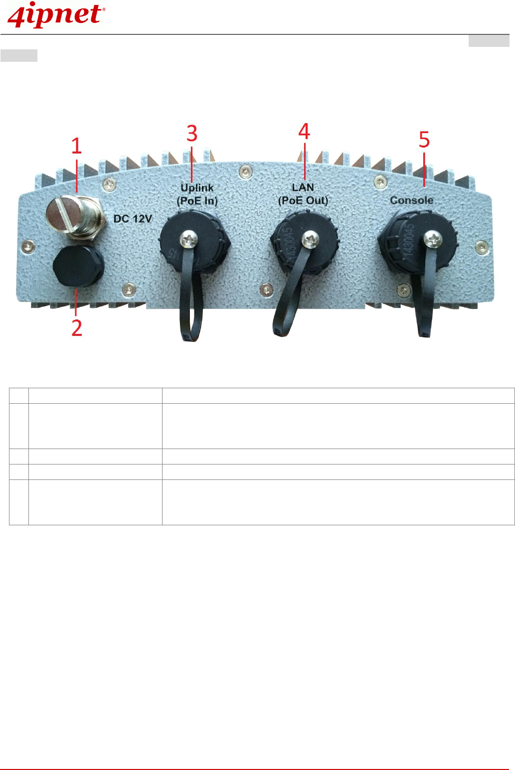
Bottom
1
M12 DC Connector
DC input (12V) is supported on OWL630
2
Ventilation Valve
Due to extreme weather conditions, water vapor in the OWL630 may
condense. The valve allows ventilation to prevent moisture buildup within
the OWL630.
3
Uplink (PoE Connector)
For connecting to the Power Sourcing Equipment (PSE)
4
Ethernet LAN
Attach Ethernet cables here for connecting to the wired local network
5
Console
The system can be configured via a serial console port. The administrator
can use a terminal emulation program such as Microsoft’s Hyper Terminal
for troubleshooting purposes.

Handbook
OWL630 Enterprise Access Point ENGLISH
Copyright © 4IPNET, INC. All rights reserved.
4
Hardware Installation
The following are the basic installation steps which can be used for testing and configuring the OWL630.
Installation Steps:
Step 1. Connect an antenna to the connector.
Step 2. Connect the Ethernet Port of OWL630 to the POWER & DATA OUT Port of the PSE.
Step 3. Connect one end of an Ethernet cable to the Data Port of PSE and the other end to the computer.
Step 4. Power on the PSE in order to supply power to the OWL630.
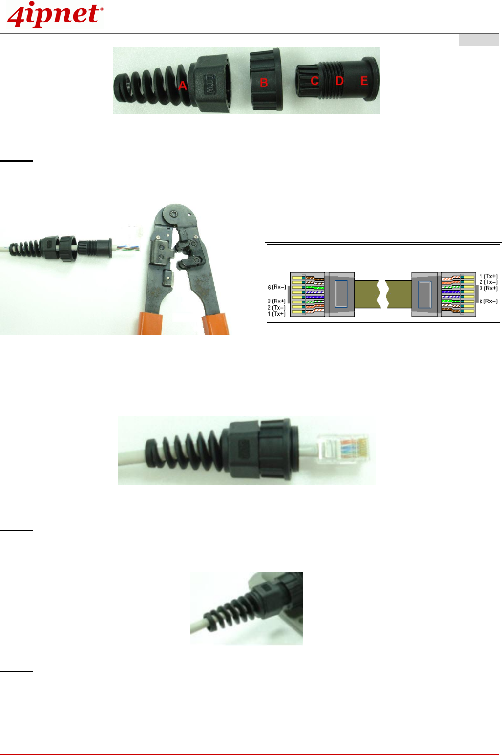
Installing the Waterproof Connection Pack:
A connector pack as shown in the figure below is included with the system.
Parts Included: 5 Parts – Part-A ~ Part-E
Step 1. Take the white sticker off Part E and attach it to Part-D.
Step 2. Plug Part-C into Part-D. There will be three main parts as shown below.
Handbook
OWL630 Enterprise Access Point ENGLISH
Copyright © 4IPNET, INC. All rights reserved.
5
Step 3. Insert the cable through the main parts and install a RJ-45 connector using straight-through method
(both ends are in the same wiring order: 1 (Tx+), 2 (Tx-), 3 (Rx+), 6 (Rx-)).
Example after the RJ-45 connector is installed,
Step 4. Plug the RJ-45 Connector into the system and make sure the locking ring is locked in well.
Step 5. Coil waterproof tape to secure the parts of the Waterproof Connector Pack.
Straight-Through Cable Wiring
Handbook
OWL630 Enterprise Access Point ENGLISH
Copyright © 4IPNET, INC. All rights reserved.
6
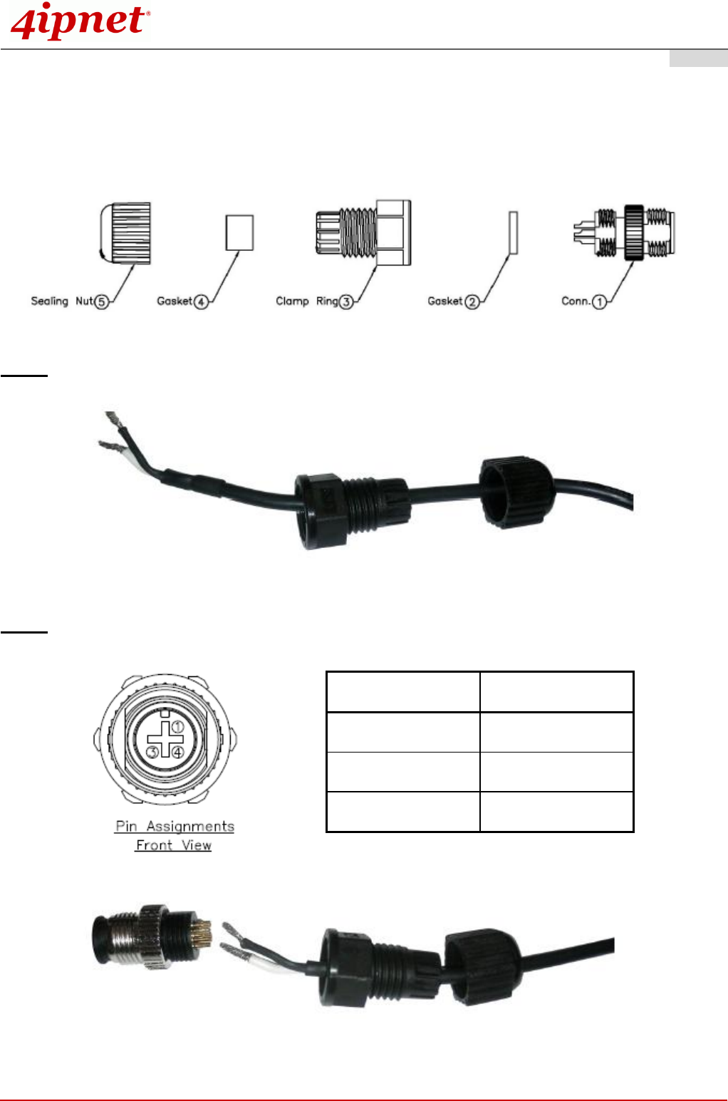
Installing the Waterproof Connection Pack (Optional):
The M12 Waterproof Connector Pack is used for DC power supply, and it consists of 5 parts:
Step 1. Pass power cable through the Sealing Nut, Gaskets, and Clamp Ring (items 2-5)
Step 2. Solder power pins with reference to the pin definition below
Pin Number
Pin Definition
1
V+
3
V–
4
NC

Handbook
OWL630 Enterprise Access Point ENGLISH
Copyright © 4IPNET, INC. All rights reserved.
7
Step 3. Seal all connectors and fasten sealing nuts
Now, the Hardware Installation is complete. For installation instruction on mounting, please refer to the Installation
Guide.

Handbook
OWL630 Enterprise Access Point ENGLISH
Copyright © 4IPNET, INC. All rights reserved.
8
Getting Started
4ipnet OWL630 supports web-based configuration. Upon the completion of hardware installation, Access
Point can be configured through a PC by using its web browser such as Mozilla Firefox 2.0 or Internet
Explorer version 6.0 and above.
The default values of LAN IP address and subnet mask of OWL630 are:
IP Address
192.168.1.1
Subnet Mask
255.255.255.0
Steps:
1. To access the web management interface, connect the administrator PC to the LAN port of OWL630 via
an Ethernet cable. Then, set a static IP address on the same subnet mask as OWL630 in TCP/IP of your
PC, such as the following example:
IP Address: 192.168.1.100
Subnet Mask: 255.255.255.0
2. Launch the web browser on your PC by entering the IP address of OWL630 (http://192.168.1.1) at the
address field, and then press Enter.
Example of entering OWL630's default IP Address via a web browser
3. The following Admin Login Page will appear. Enter “admin” for both the Username and Password fields,
and then click Login.
Administrator Login Page
Handbook
OWL630 Enterprise Access Point ENGLISH
Copyright © 4IPNET, INC. All rights reserved.
9
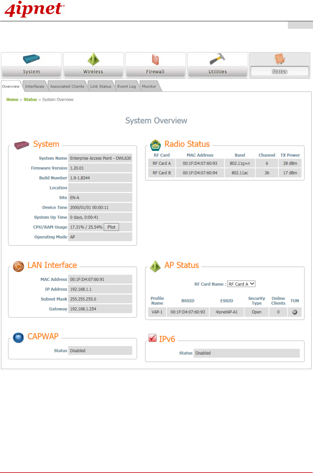
4. After a successful login into OWL630’s Web user interface (Web UI), a System Overview page of web
management interface will appear, as depicted below.
The Web Management Interface - System Overview Page
5. To logout, simply click on the Logout button at the upper right hand corner of the interface to return to the
Administrator Login Page. Click OK to logout.

Handbook
OWL630 Enterprise Access Point ENGLISH
Copyright © 4IPNET, INC. All rights reserved.
10
Common Settings
Step 1. Change Administrator’s Password
Change Password Page
Click on the Utilities main menu button, and then select the Change Password tab.
Enter a new password with a length of up to 32 characters, and retype it in the Re-enter New
Password field.
Click SAVE to save the changes.
Handbook
OWL630 Enterprise Access Point ENGLISH
Copyright © 4IPNET, INC. All rights reserved.
11
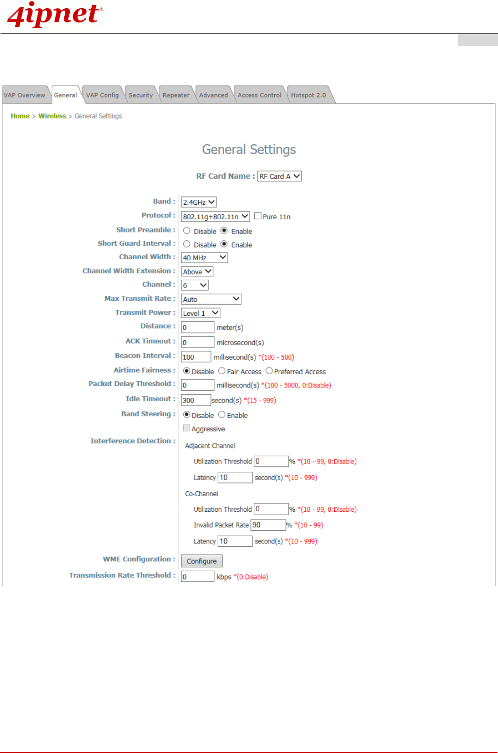
Step 2. Configure General AP (Access Point) Settings
Wireless General Settings Page
Click on the Wireless icon on the main menu, and then select the General tab.
Determine the Band, Protocol and Channel settings:
Select your preferred Band, Protocol and Channel for you wireless connection. For example, select
2.4GHz for the band, 802.11g+802.11n for the protocol and 6 for the channel.

Handbook
OWL630 Enterprise Access Point ENGLISH
Copyright © 4IPNET, INC. All rights reserved.
12
Note:
Admin should be aware of Dynamic Frequency Selection (DFS) mandated on some channels of the
5GHz band. When an OWL630 detects interference, this mechanism will limit the ability to broadcast
the SSID on one of the channels listed below:
1) Country Code: 841 (US)
DFS Channels: 52 56 60 64 100 104 108 112 116 132 136 140 149 153 157 161 165
2) Country Code: 250 (EU)
DFS Channels: 52 56 60 64 100 104 108 112 116 120 124 128 132 136 140
Handbook
OWL630 Enterprise Access Point ENGLISH
Copyright © 4IPNET, INC. All rights reserved.
13
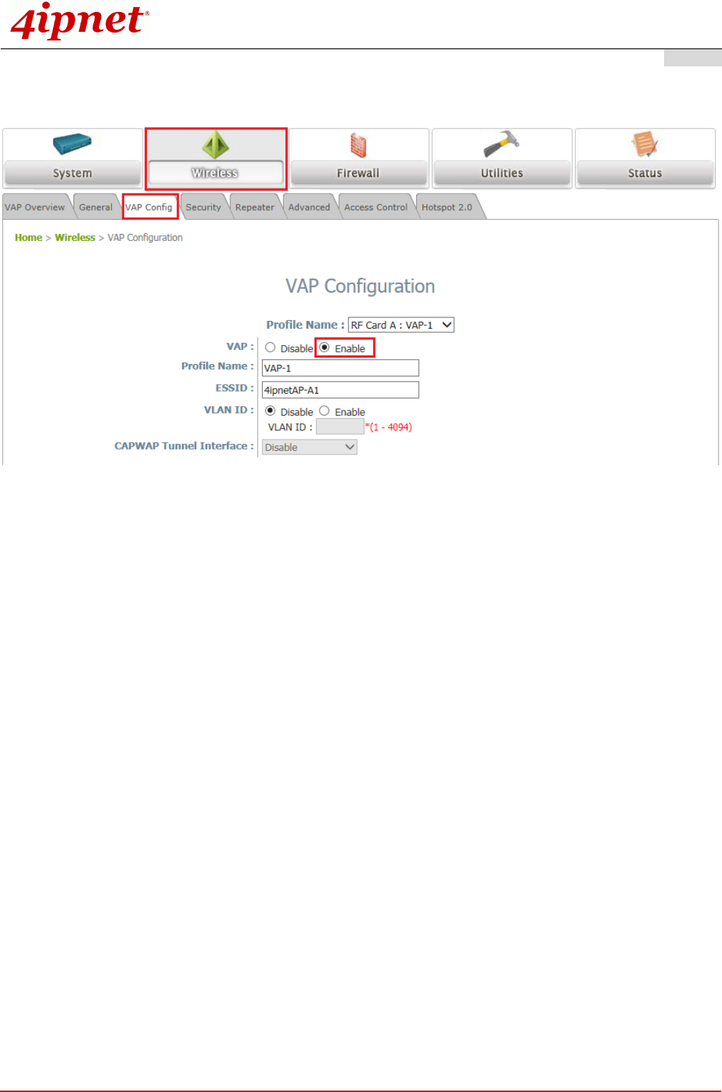
Step 3. Configure VAP (Virtual Access Point) Profile Settings
VAP Configuration Page (VAP-1 shown)
OWL630 supports up to 16 virtual APs (VAPs) per RF card.
Configure VAP profile settings:
(a) Select the VAP Config tab to configure the settings of the desired VAP.
(b) Enable a specific VAP from the drop-down menu of Profile Name and configure related settings
below.
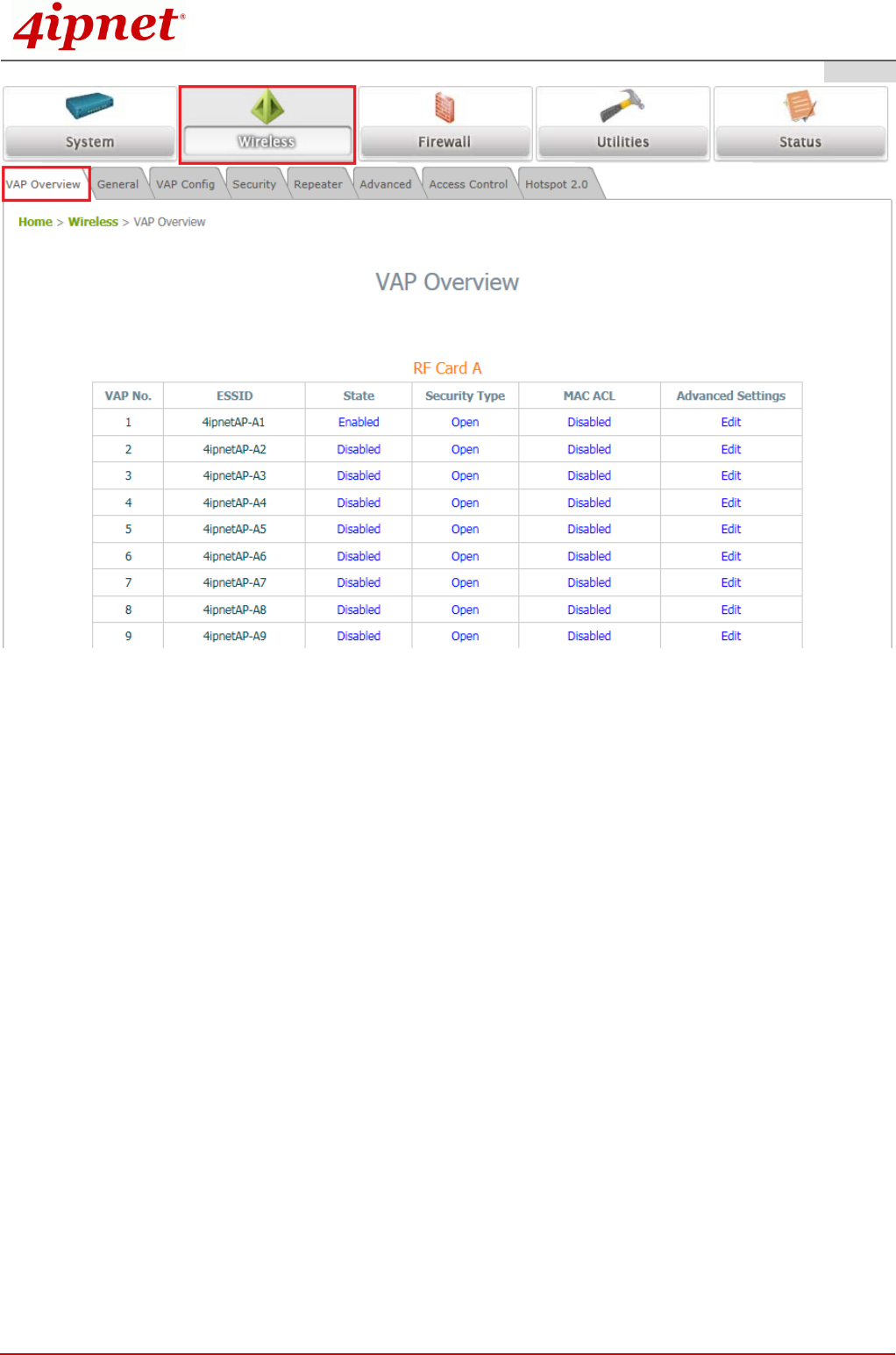
Check VAP status:
After finishing VAP configuration, the status of enabled Virtual APs shall be reflected on the VAP
Overview page.
Handbook
OWL630 Enterprise Access Point ENGLISH
Copyright © 4IPNET, INC. All rights reserved.
14
Virtual AP Overview Page
Handbook
OWL630 Enterprise Access Point ENGLISH
Copyright © 4IPNET, INC. All rights reserved.
15
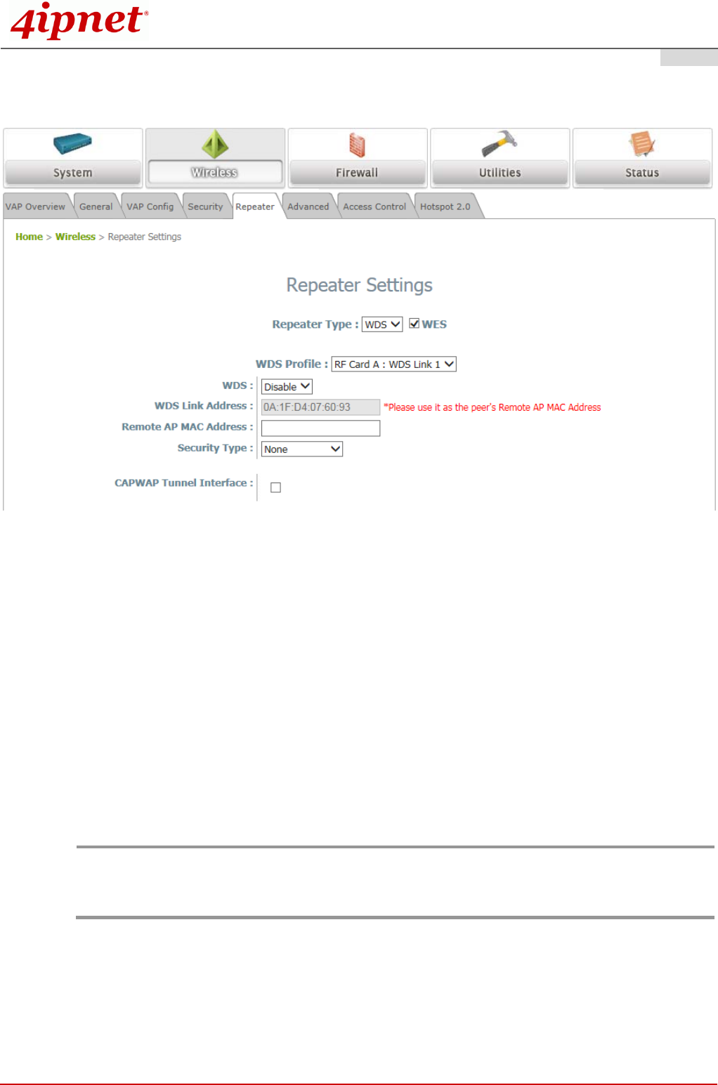
Step 4. Configure WDS (Wireless Distribution System) Settings (Optional)
To extend the wireless coverage, OWL630 supports up to 8 WDS links for connecting wirelessly to other
WDS-capable APs (peer APs). By default, all WDS profiles are disabled.
Click on the Wireless main menu button.
Select the Repeater tab.
Choose WDS as the Repeater Type.
Choose the desired WDS profile:
(a) Enable the WDS.
(b) Enter the Remote AP MAC Address (peer AP) and then Click SAVE.
If you use another OWL630 as the peer AP, simply repeat the above-mentioned steps to configure another
peer AP(s).
Note:
On each and every configuration page, you may click SAVE to save the changes of your configured
settings, but you must reboot the system for the changes to take effect. After clicking SAVE, the
following message will appear: “Some modifications have been saved and will take effect after
APPLY.”

Handbook
OWL630 Enterprise Access Point ENGLISH
Copyright © 4IPNET, INC. All rights reserved.
16
Congratulations!
Now, 4ipnet OWL630 is installed and configured successfully.
After OWL630's network configuration is completed, please remember to change the IP Address of
your PC Connection Properties back to its original settings in order to ensure that your PC functions
properly in its real network environments.
It is strongly recommended to make a backup copy of the configuration settings.
For further configuration and backup information, please refer to the User’s Manual.
P/N: V10020160331