4IPNET MSG100G001 Multi Service Wireless Office Gateway User Manual manual
4IPNET, INC. Multi Service Wireless Office Gateway manual
UserManual.wiki
>
4IPNET
>
MSG100G001 User Manual
manual
Navigation menu
Upload a User Manual
Namespaces
Wiki Guide
HTML
PDF
Info
Views
User Manual
Discussion / Help
Navigation
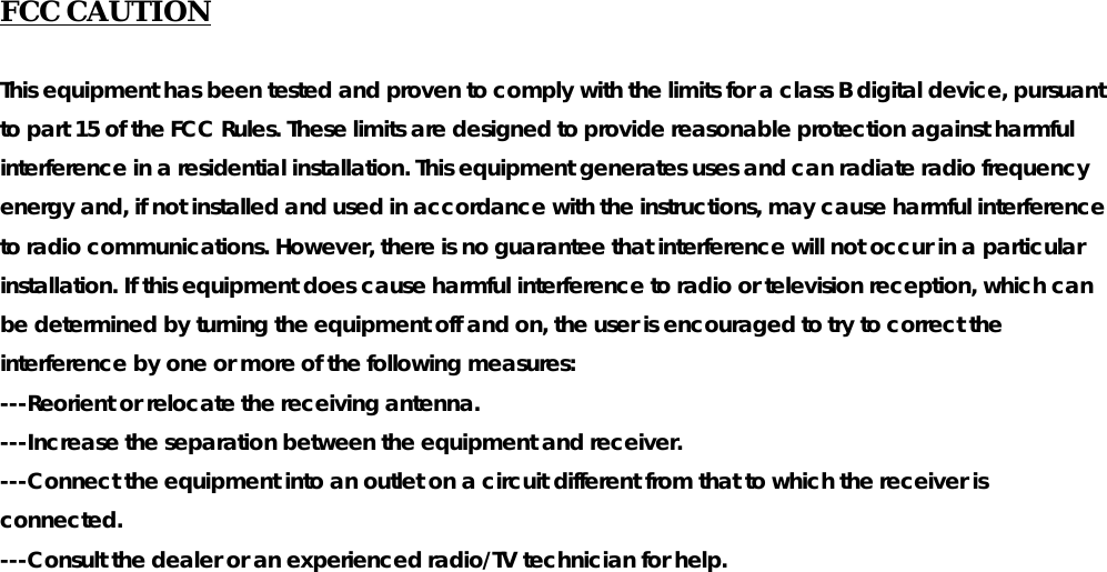
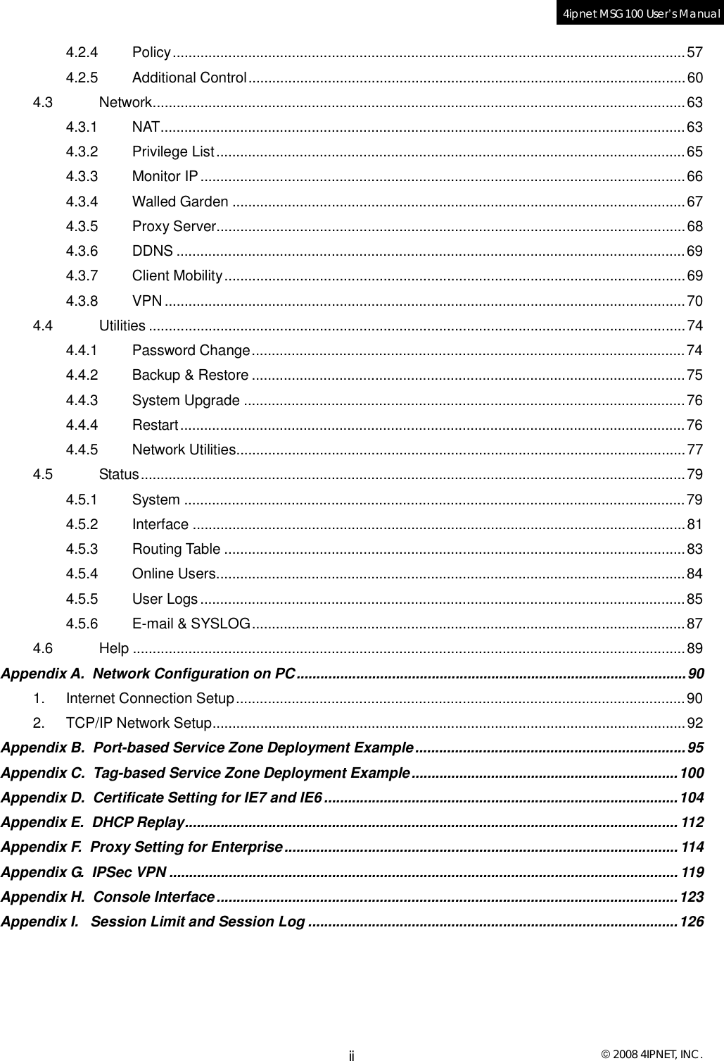
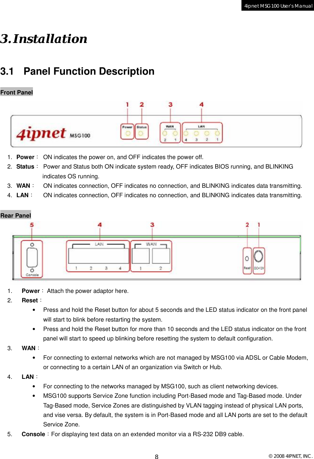
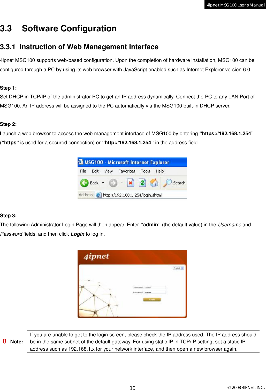
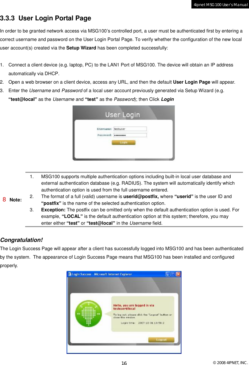
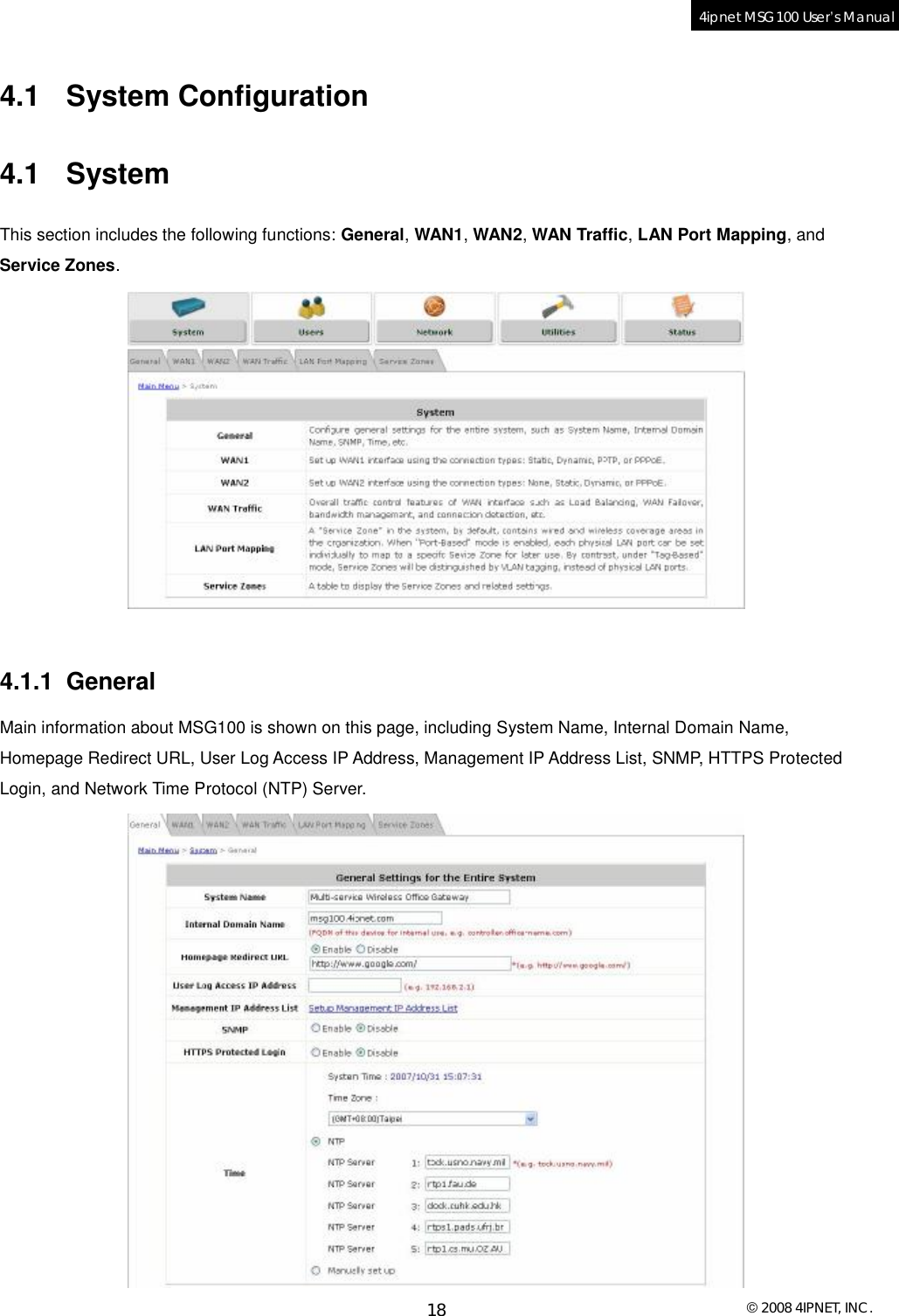
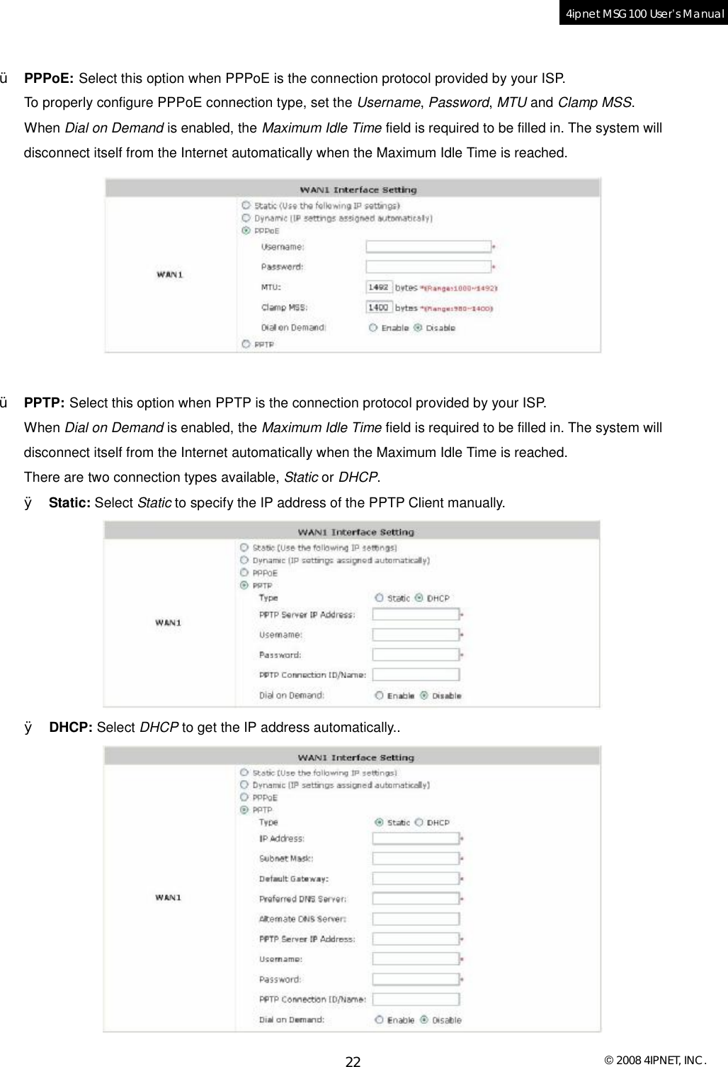
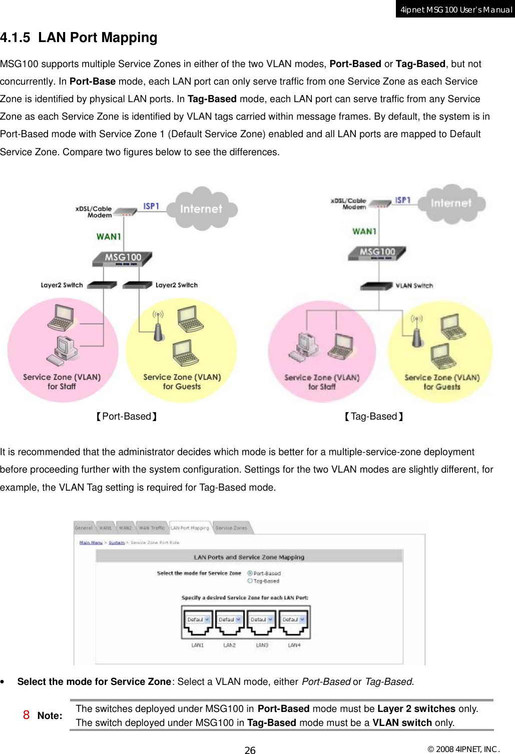
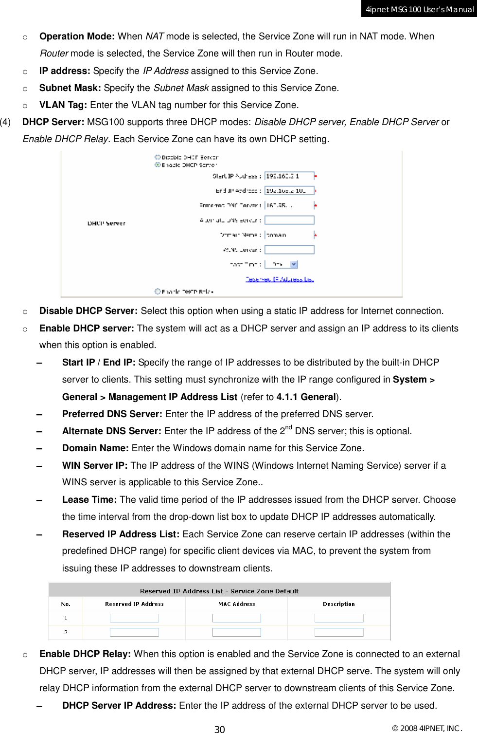
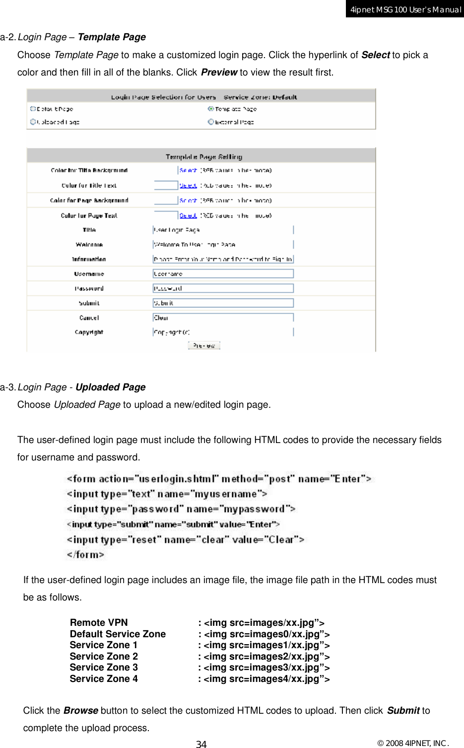
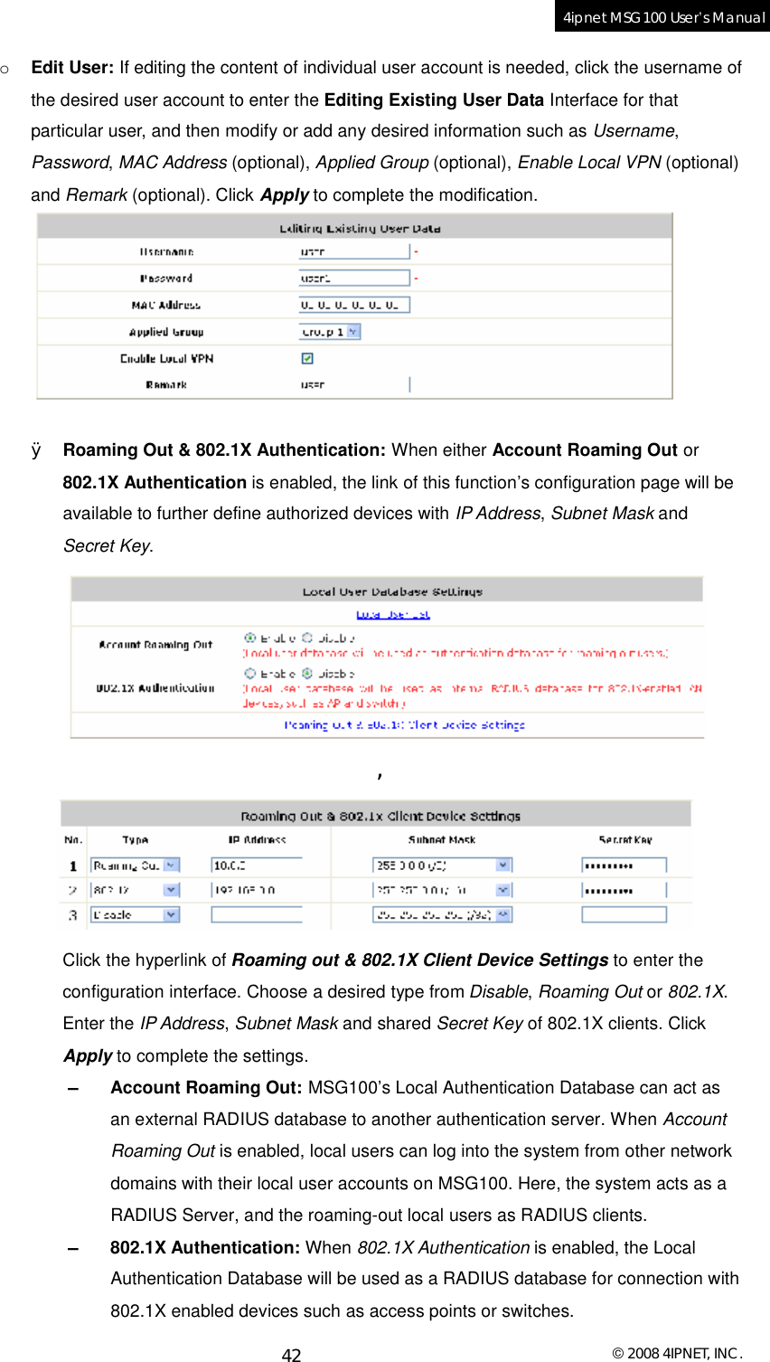
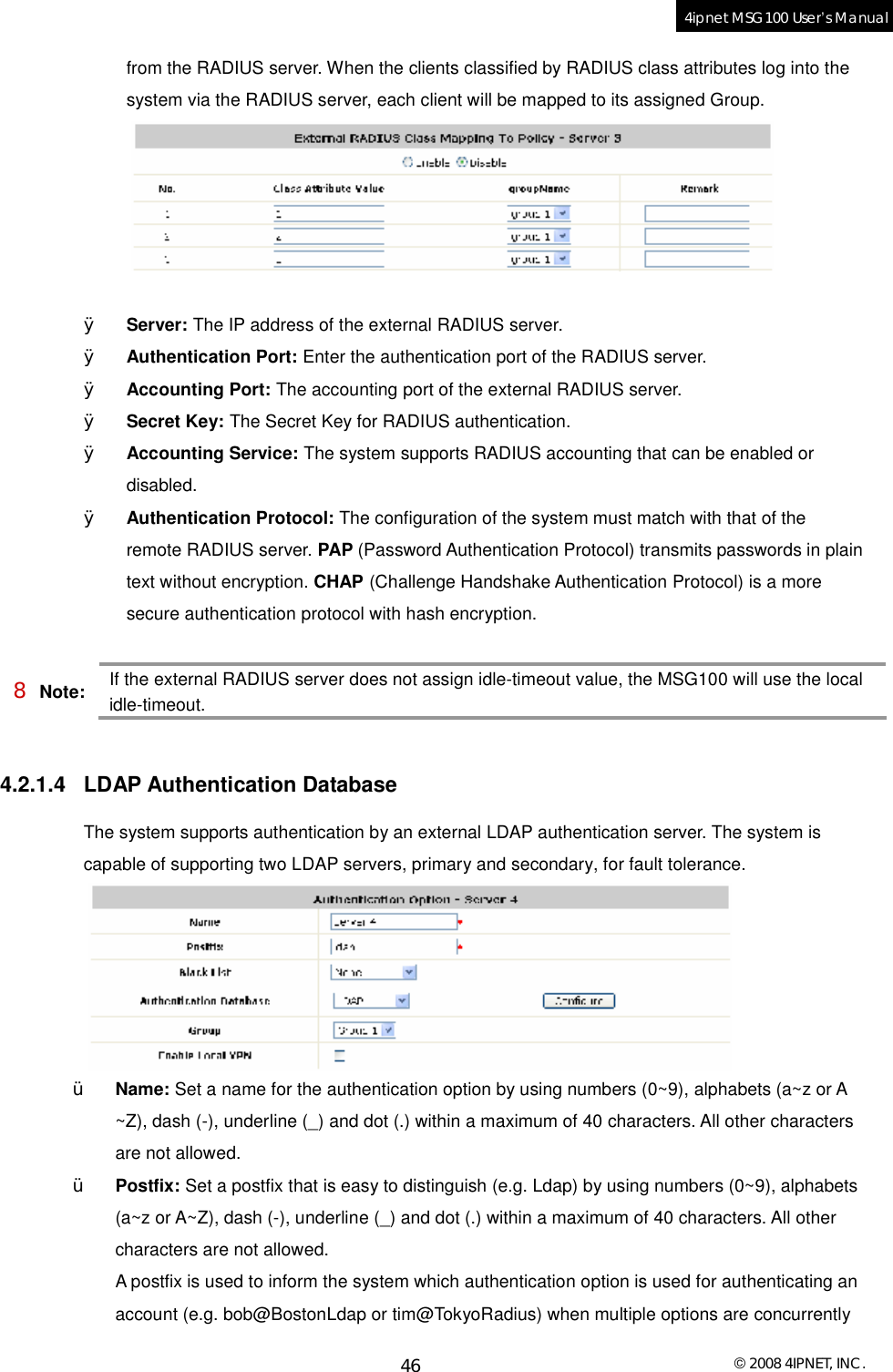
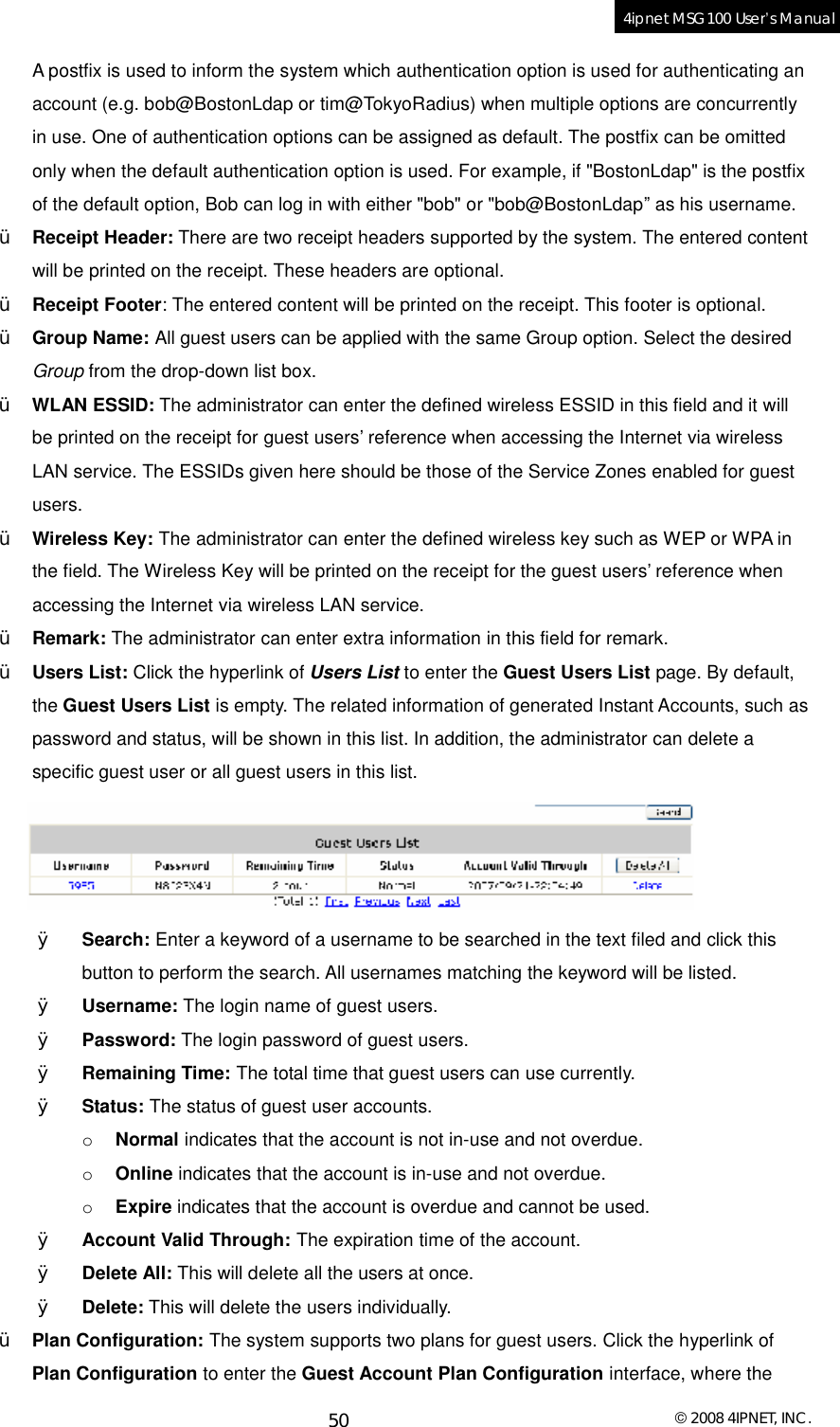
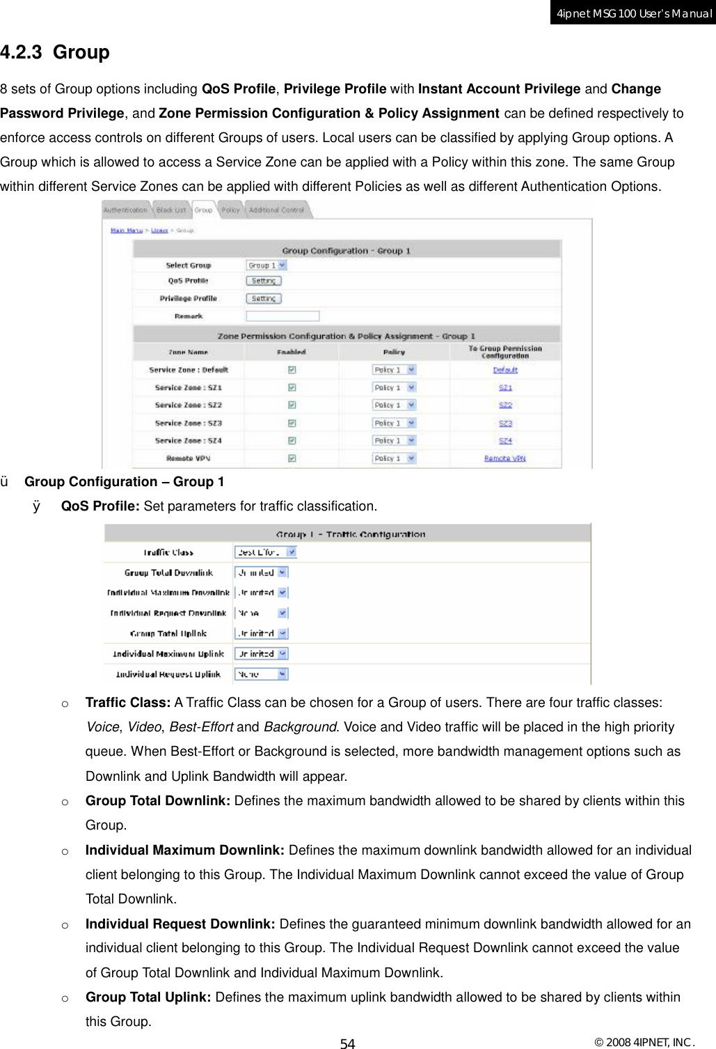
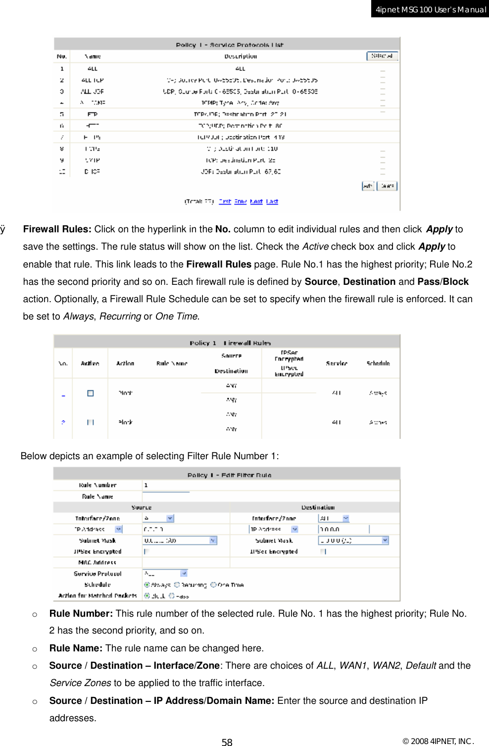
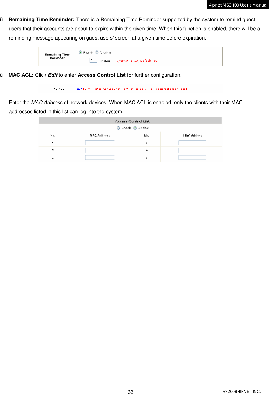
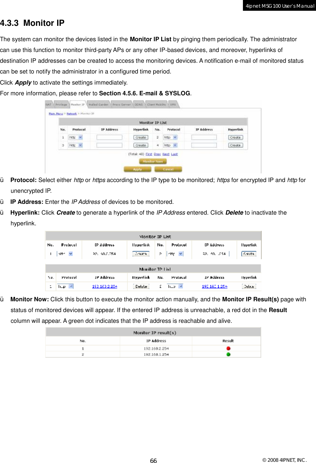
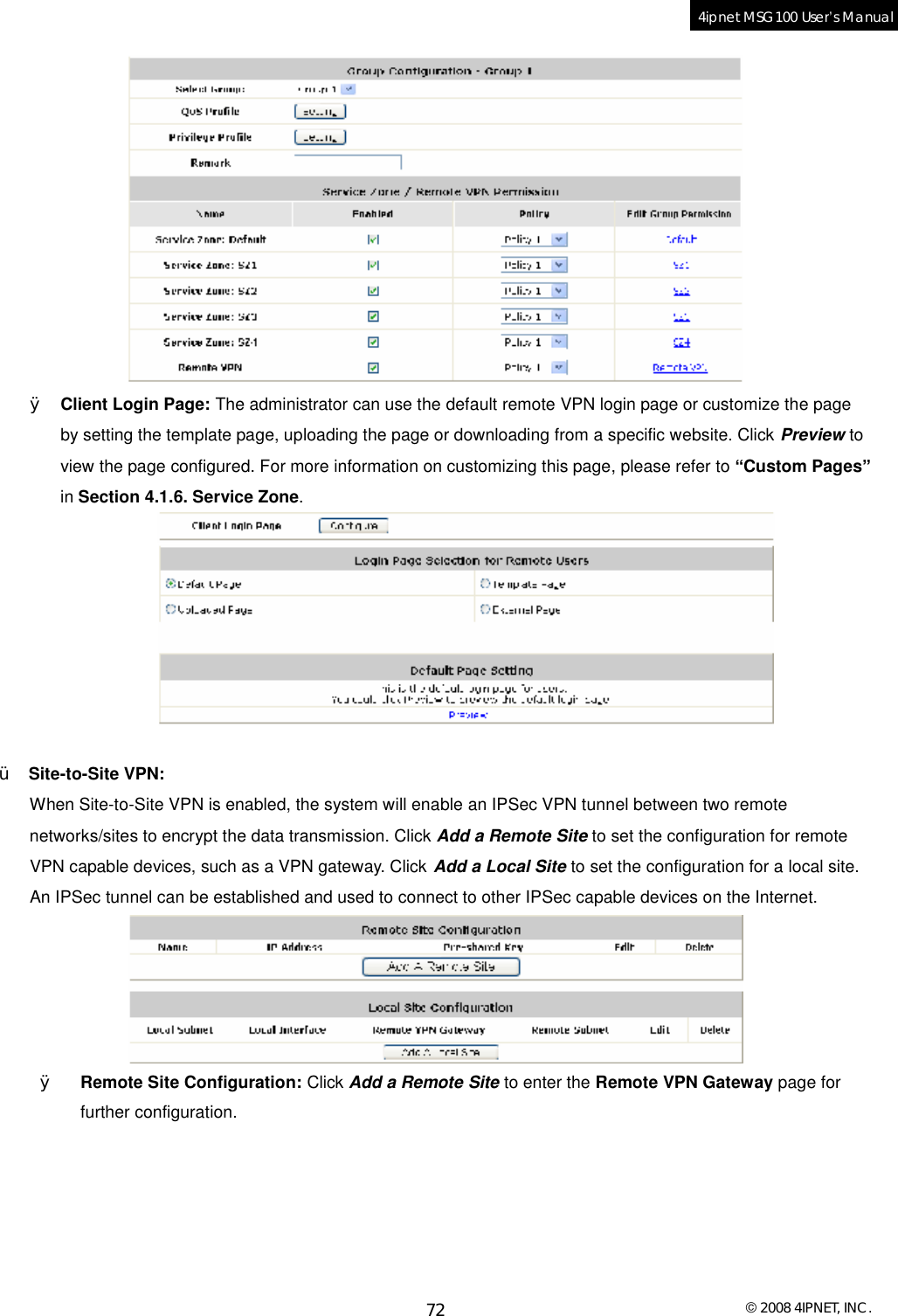
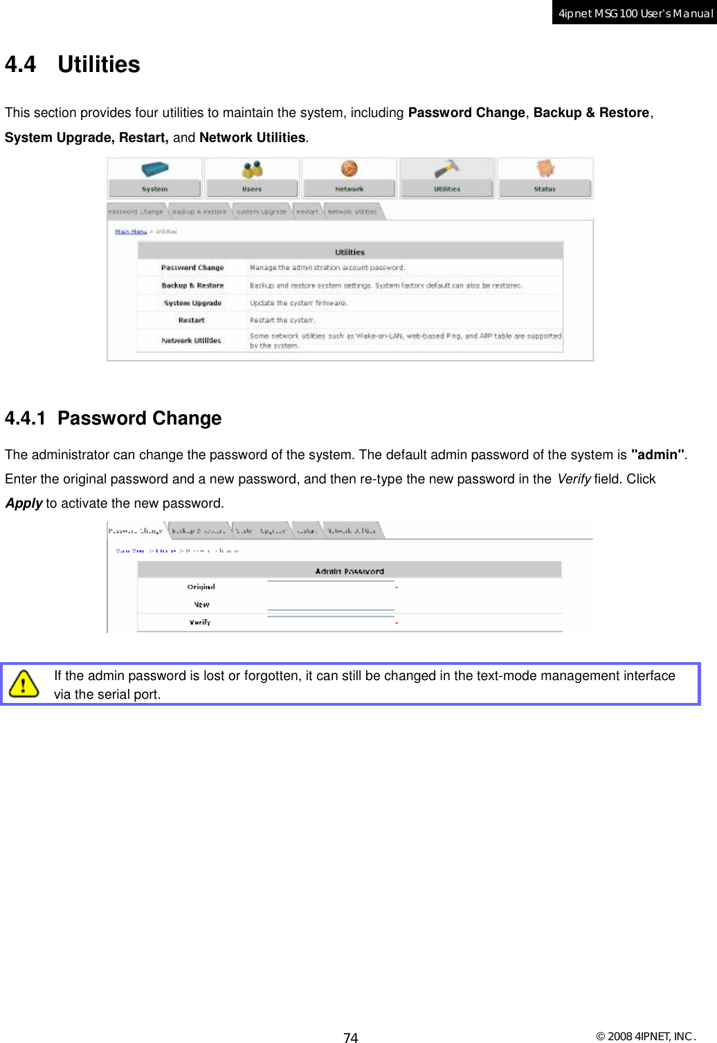
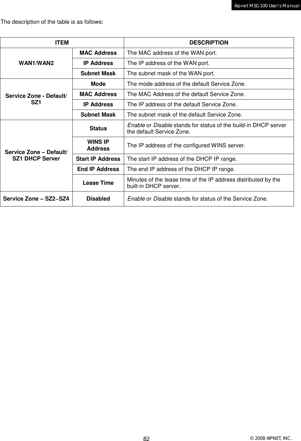
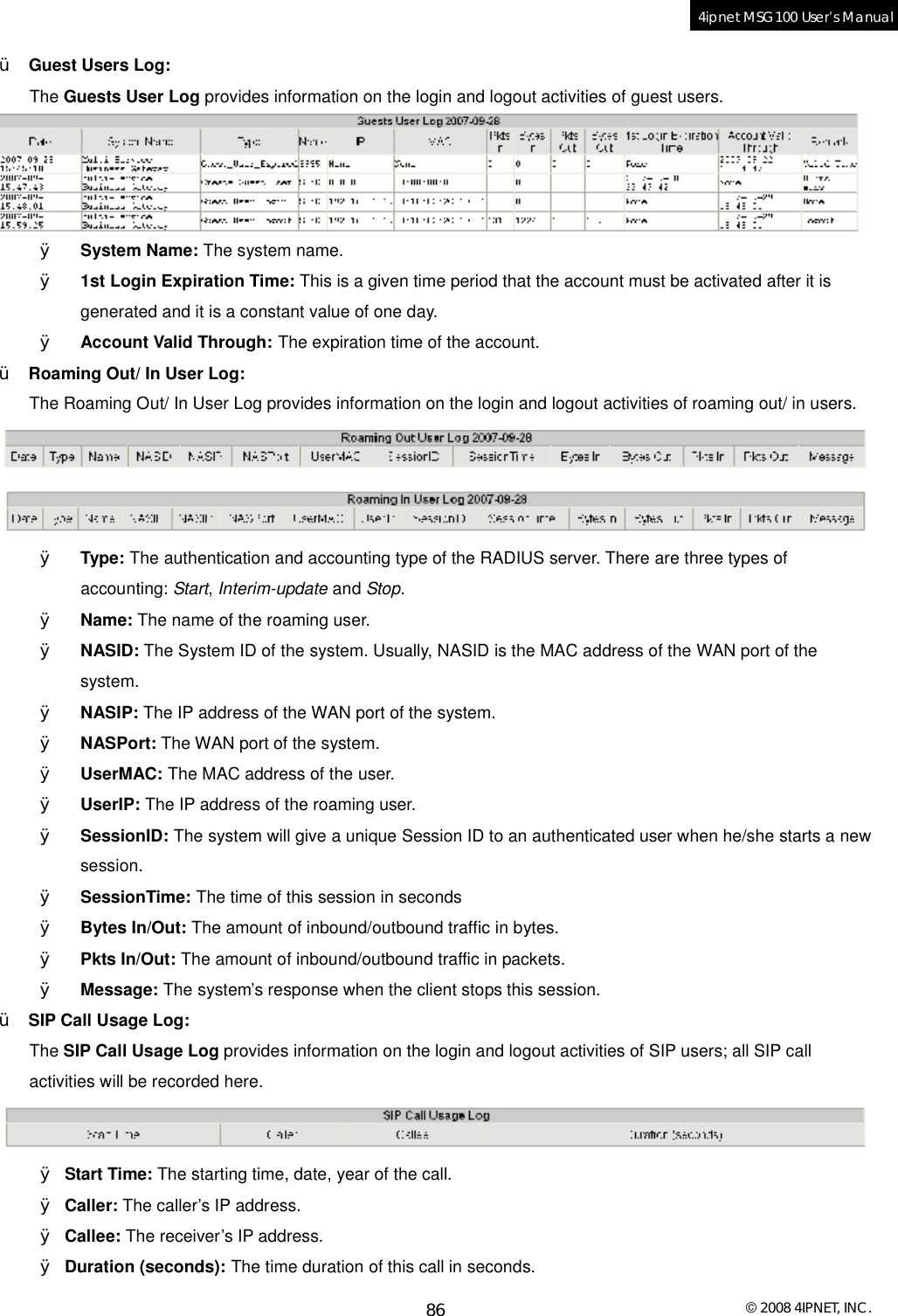
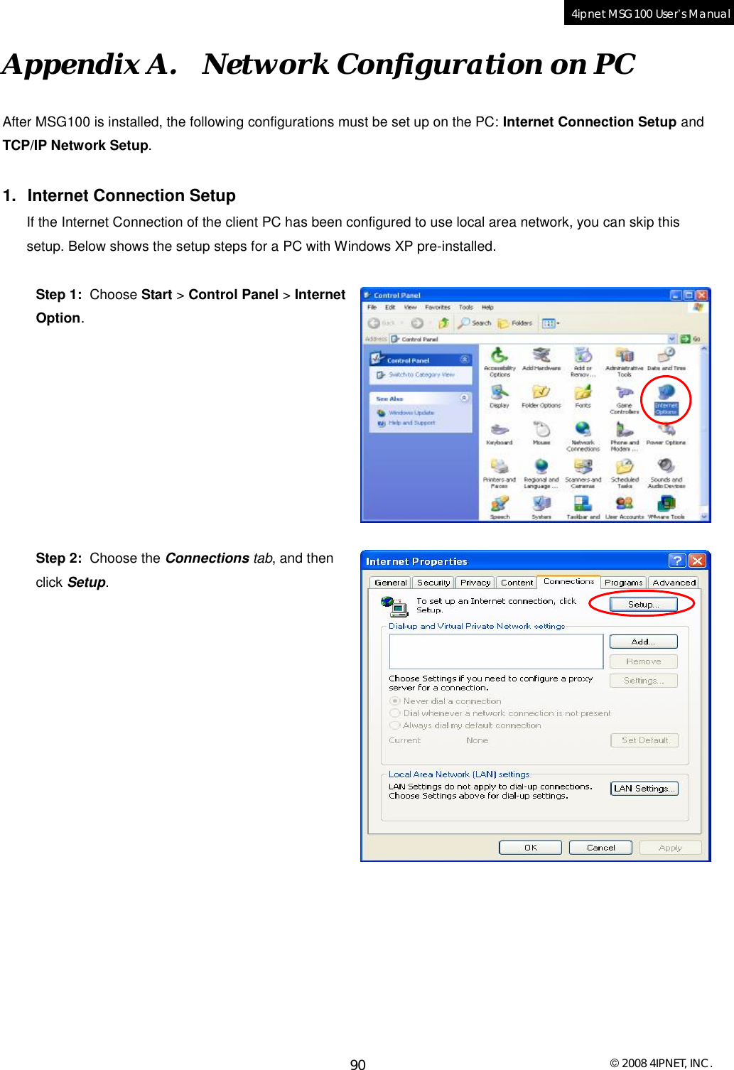

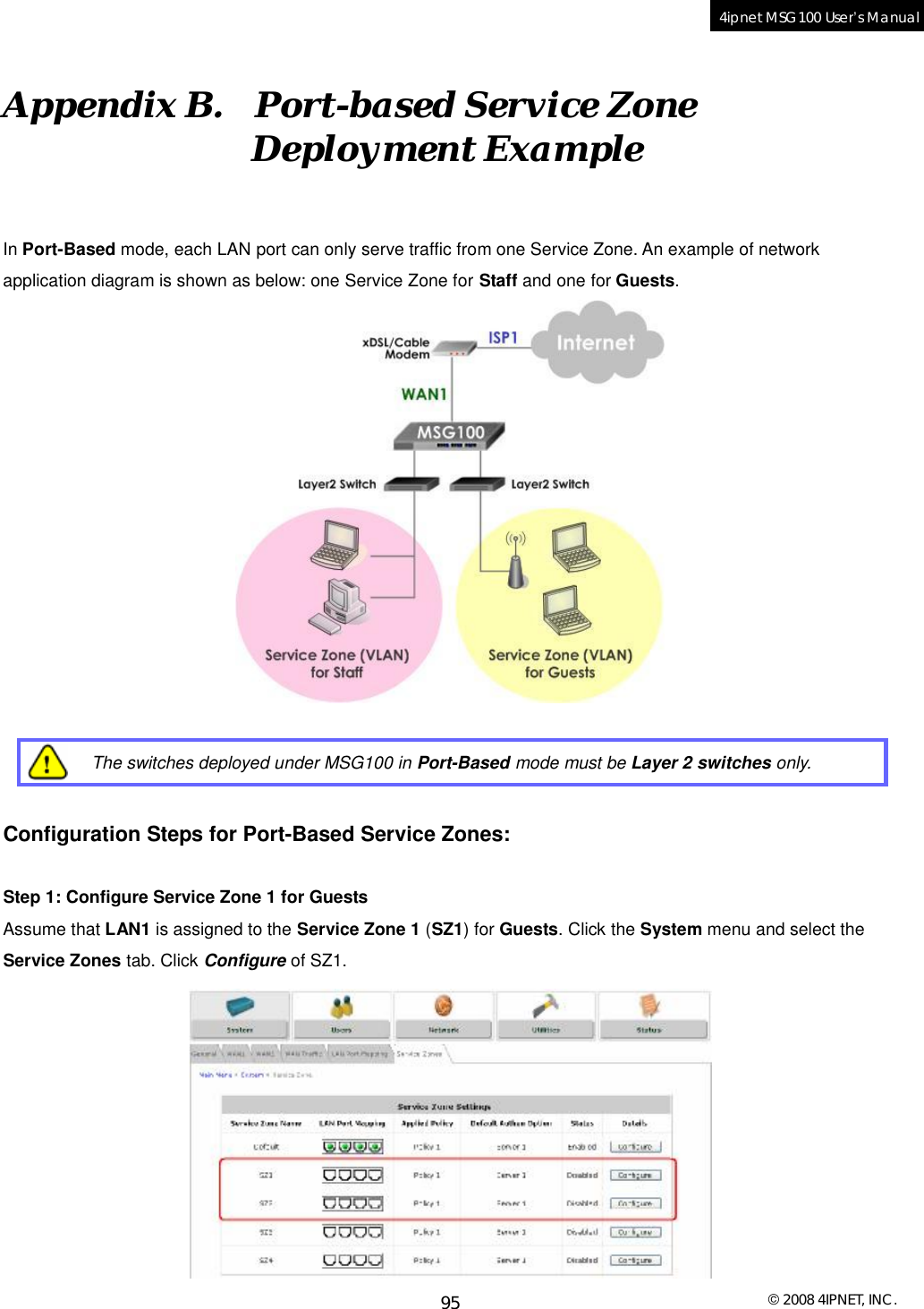
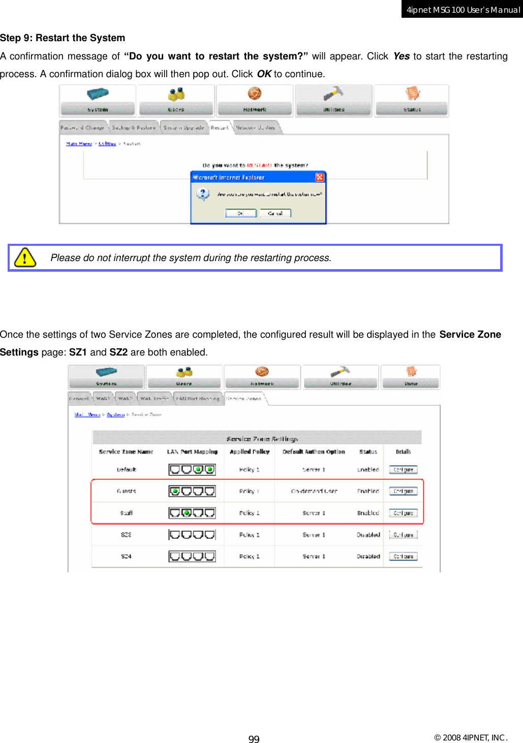
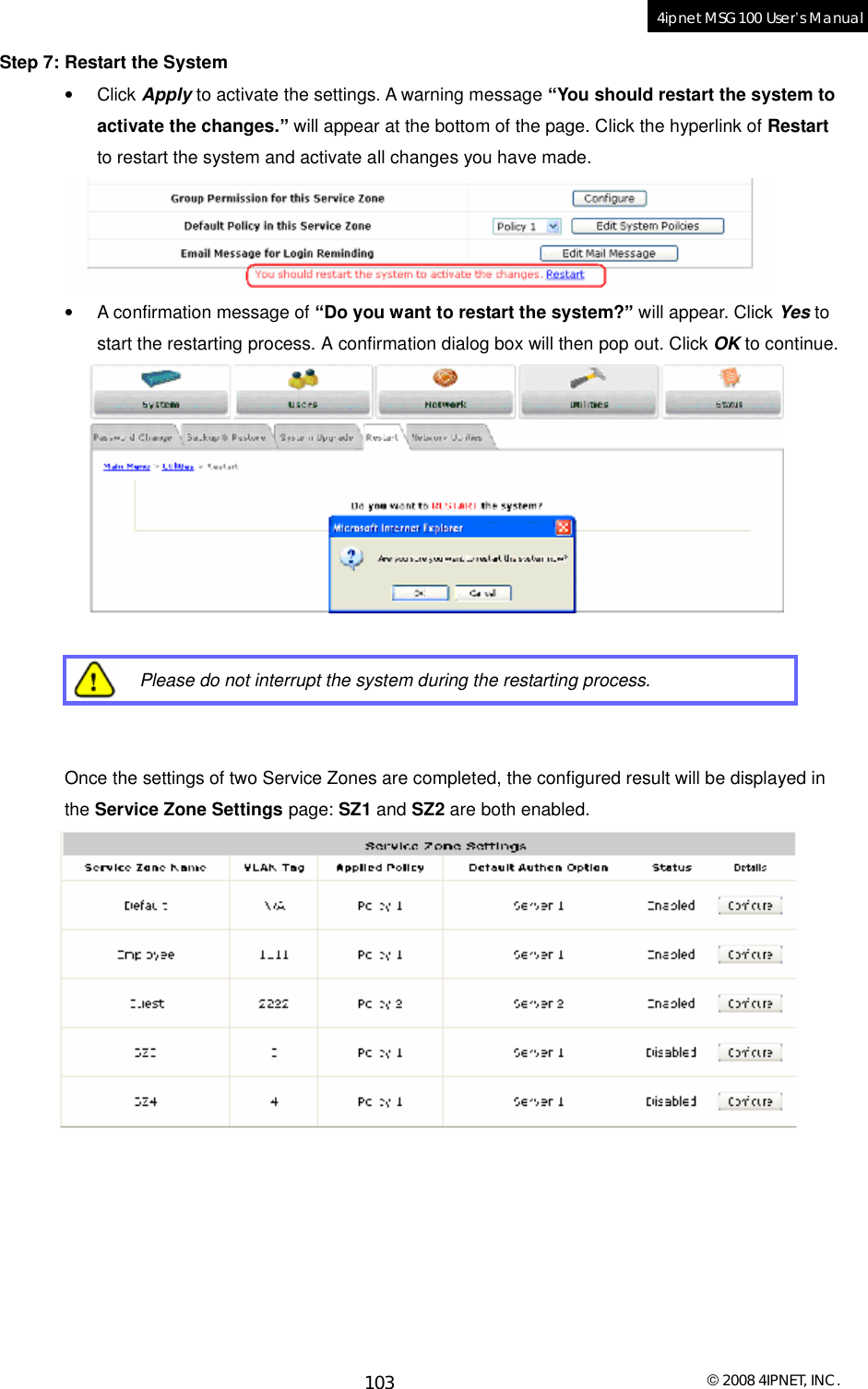
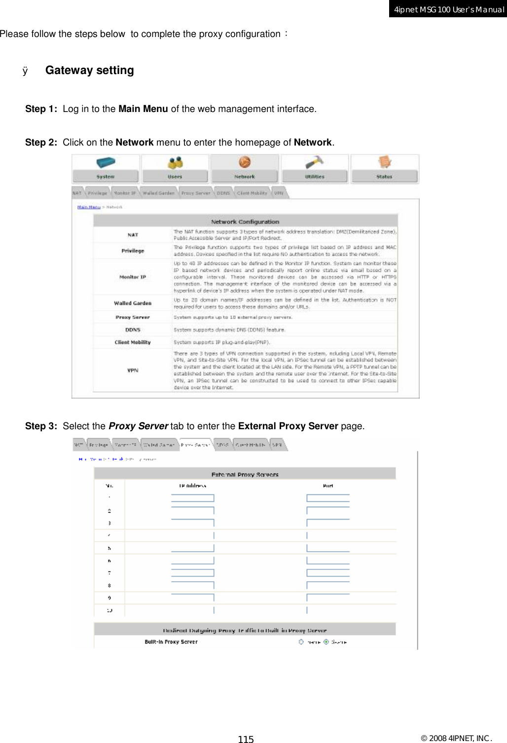
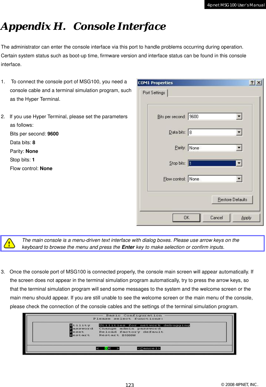
![© 2008 4IPNET, INC. 126 4ipnet MSG100 User’s Manual Appendix I. Session Limit and Session Log • Session Limit To prevent ill-behaved clients or malicious software from using up system’s connection resources, the administrator will have to restrict the number of concurrent sessions that a user can establish. Ø The maximum number of concurrent sessions (TCP and UDP) for each user can be specified in the policy setting, which can be chosen to apply to all users including authenticated users, users on non-authenticated ports, privileged users, and clients in virtual server and DMZ zones. Ø When the number of a user’s sessions reaches the session limit (a choice of Unlimited, 10, 25, 50, 100, 200, 350, and 500), the user will be implicitly suspended upon receipt of any new connection request. In this case, a record will be logged to the Syslog server specified in the Email & SYSLOG. Ø Since this basic protection mechanism may not be able to protect the system from all malicious DoS attacks, it is strongly recommended to build some immune capabilities (such as IDS or IPS solutions) in the network deployment to protect the network in daily operation. • Session Log The system can record connection details of each client while accessing the Internet. In addition, the log data can be sent out to a specified Syslog Server, Email Box or FTP Server based on pre-defined interval time. Ø The following table shows the fields of a session log record. Field Description Date and Time The date and time that the session is established Session Type [New]: This is a newly established session. [Blocked]: This session is blocked by a Firewall rule. Username The account name (with postfix) of the user. When it shows “N.A.”, it indicates that the user or device does not need to log in with a username, for example, the user or device is on a non-authenticated port or on the privileged MAC/IP list. Change the account name accordingly, if the name is not identifiable in the record. 8 Note: Only 31 characters are allowed for the combination of Session Type plus Username. Protocol The communication protocol of session: TCP or UDP MAC The MAC address of the client computer or device SIP The source IP address of the client computer or device SPort The source port number of the client computer or device DIP The destination IP address of the client computer or device DPort The destination port number of the client computer or device](https://usermanual.wiki/4IPNET/MSG100G001/User-Guide-910821-Page-129.png)
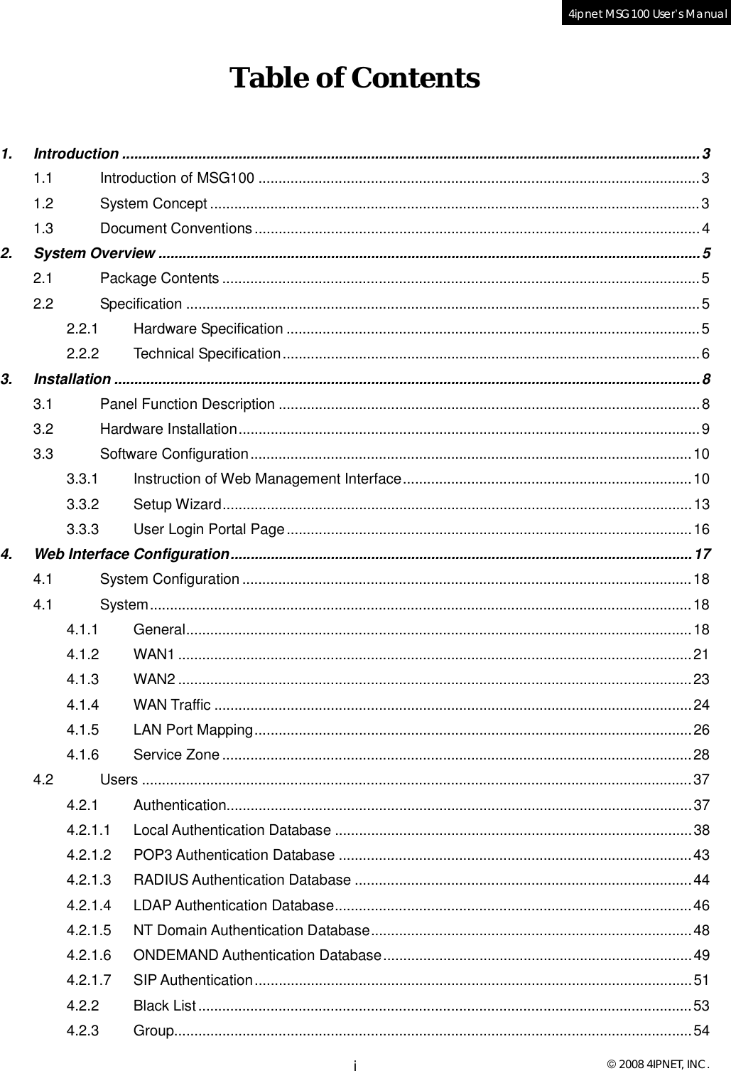
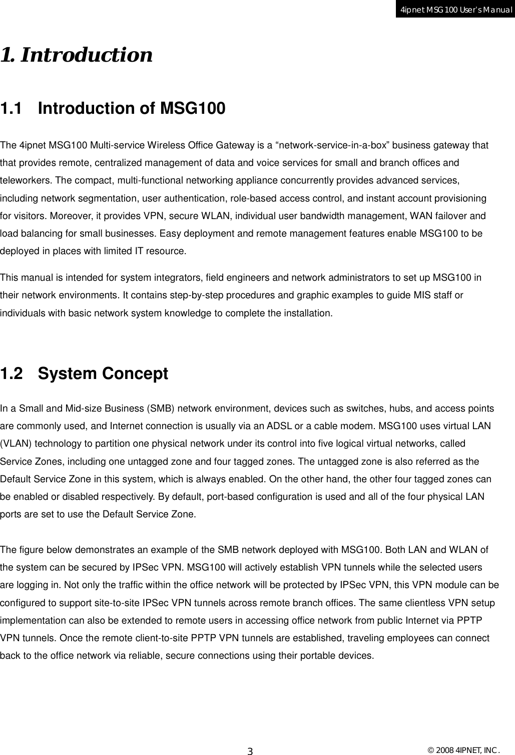
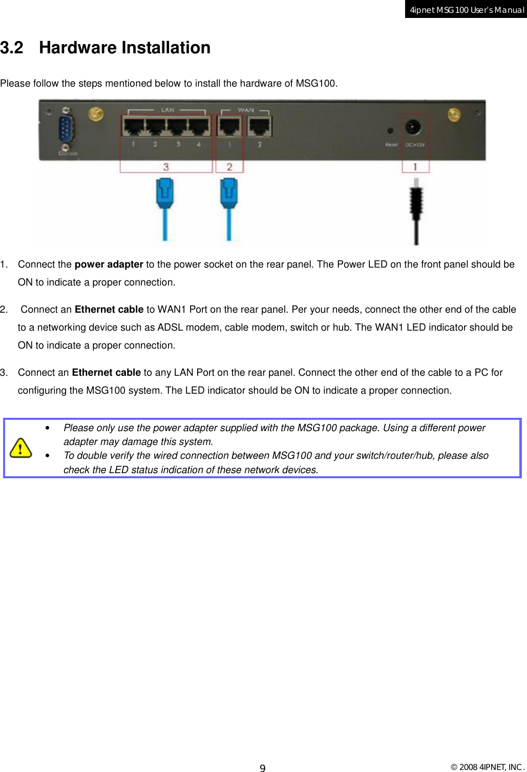
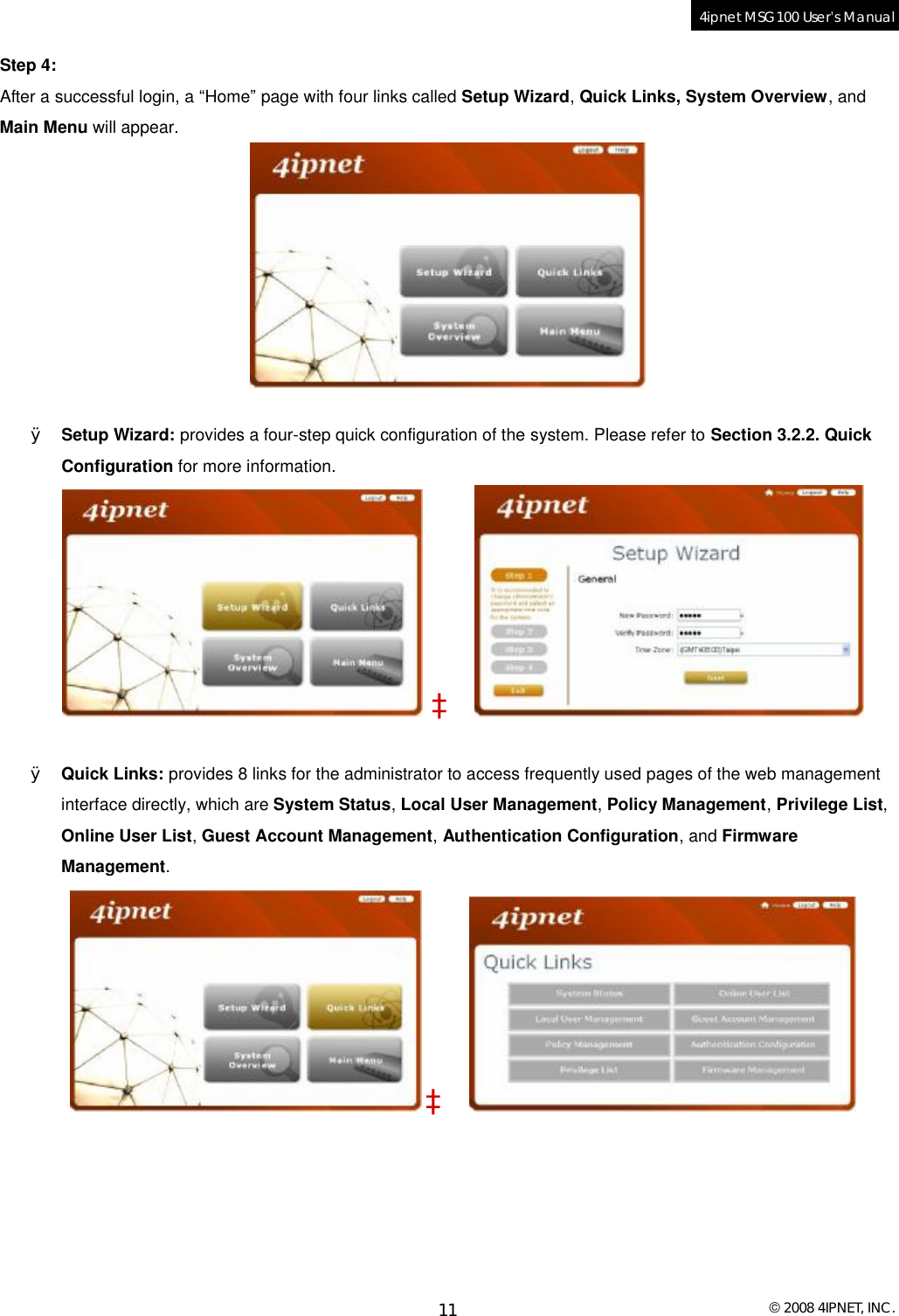
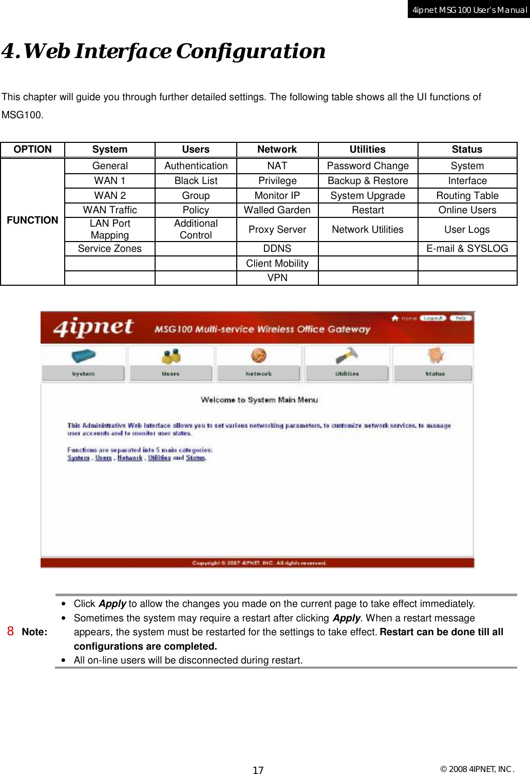
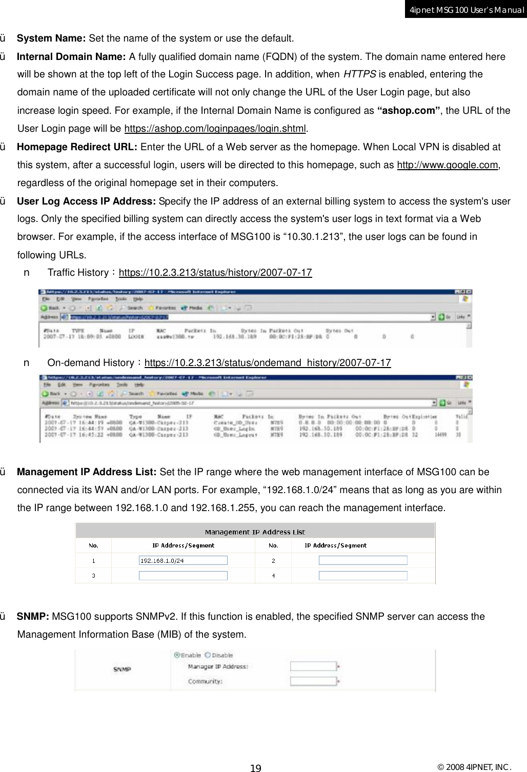
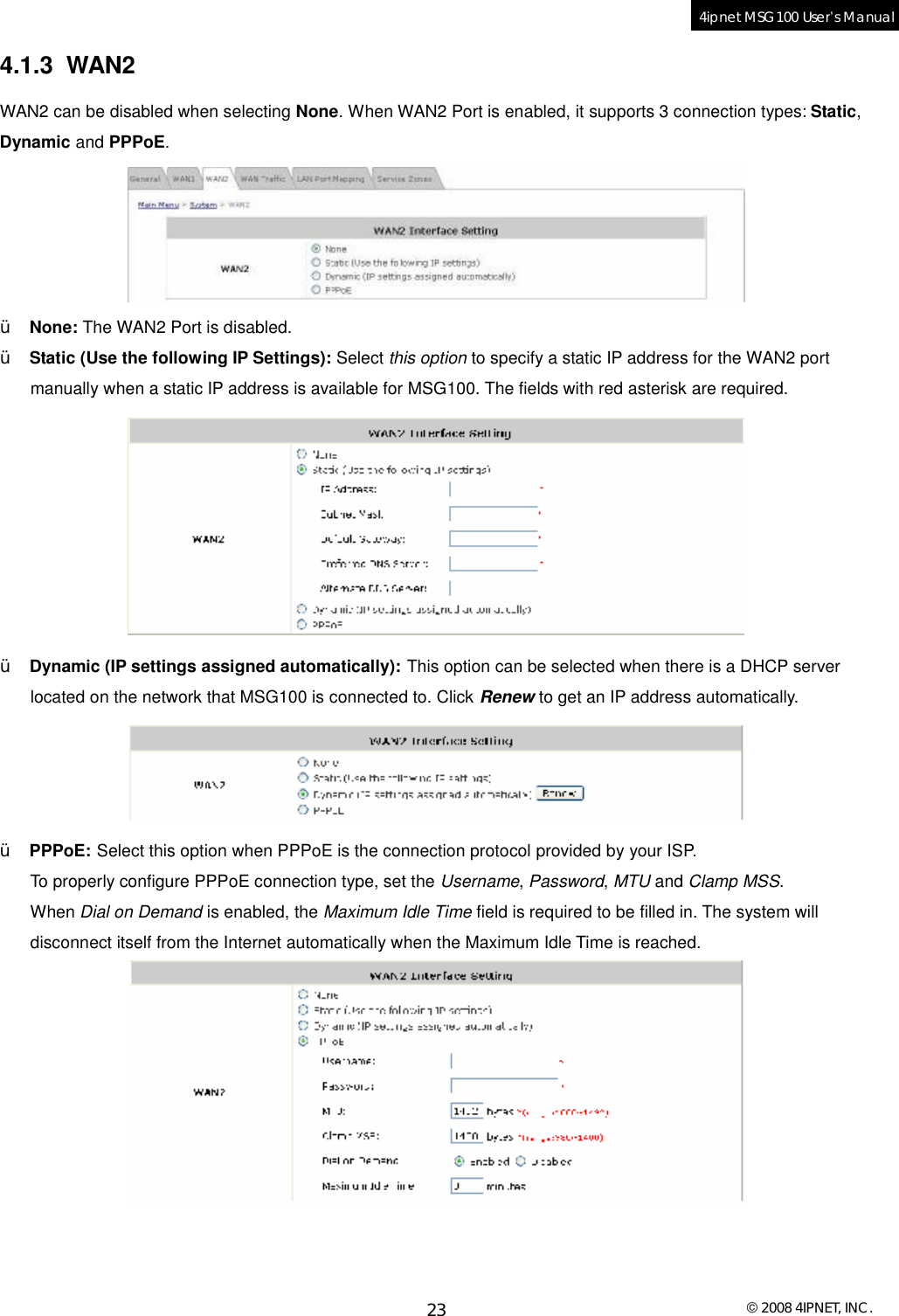
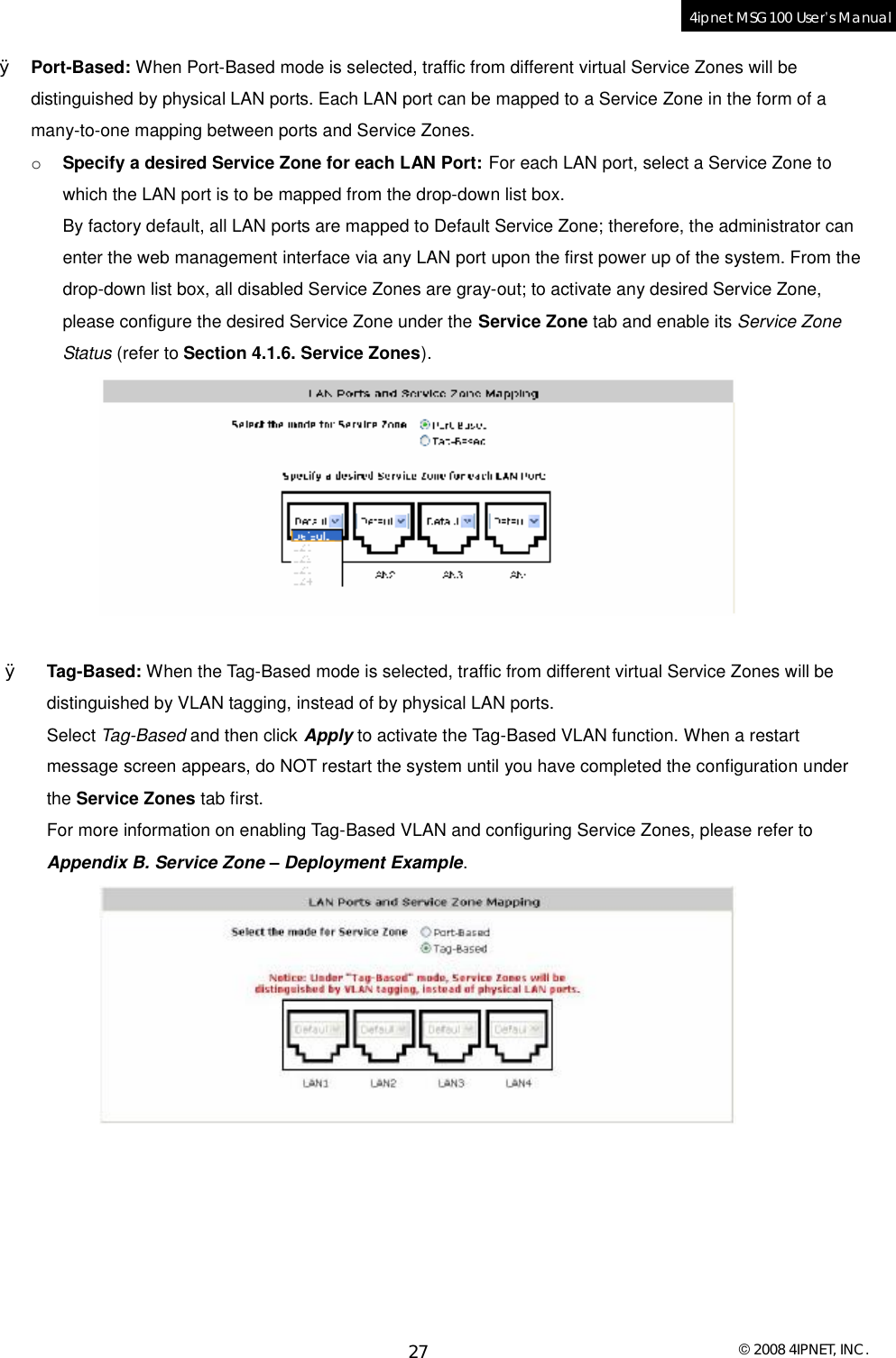
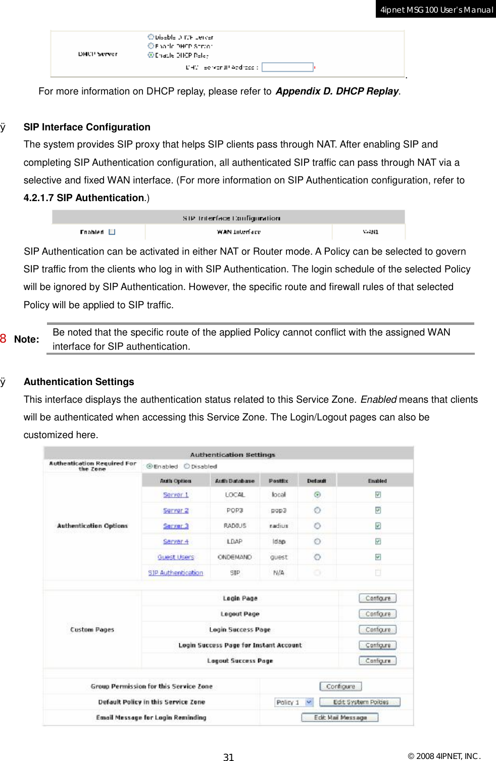
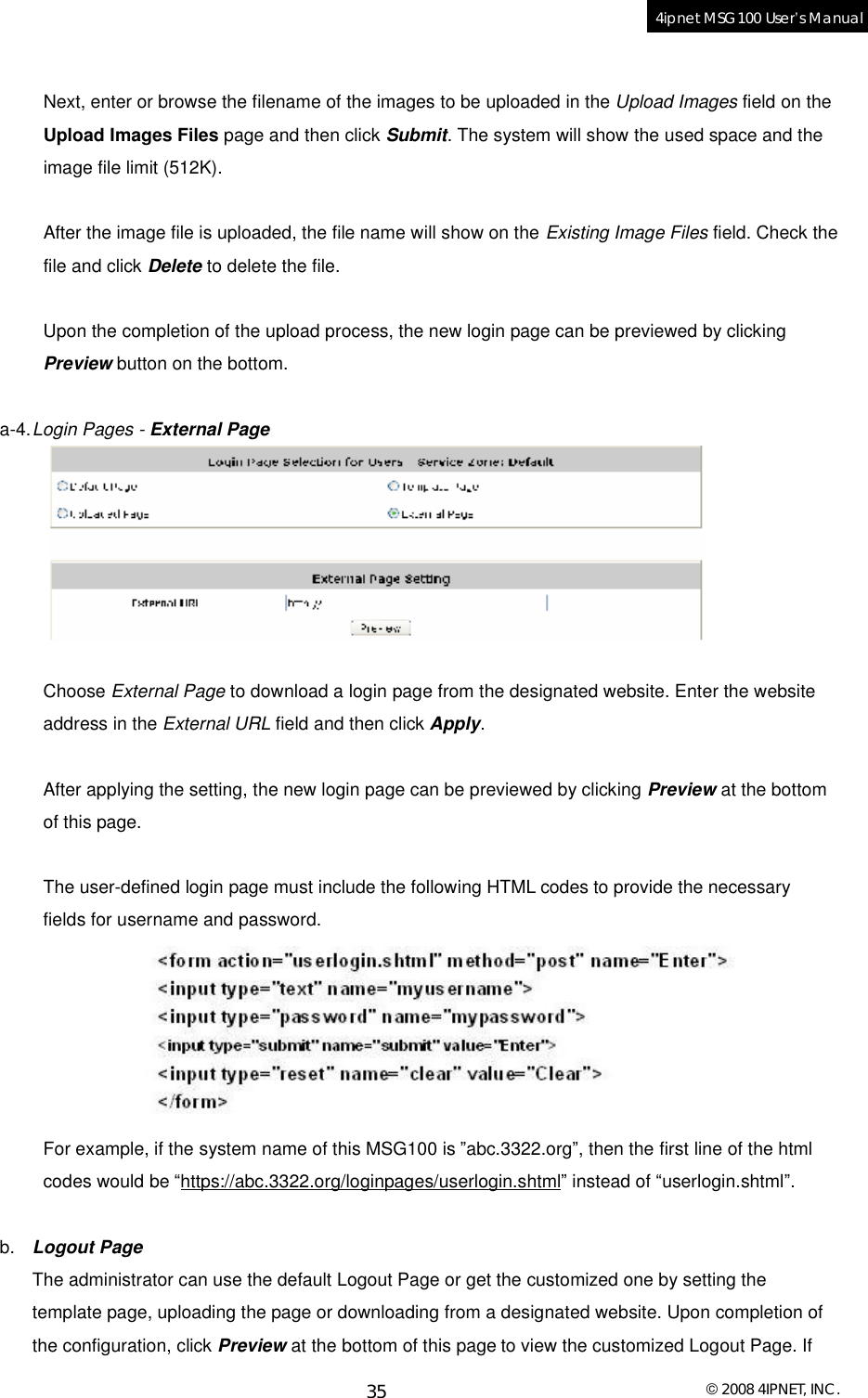
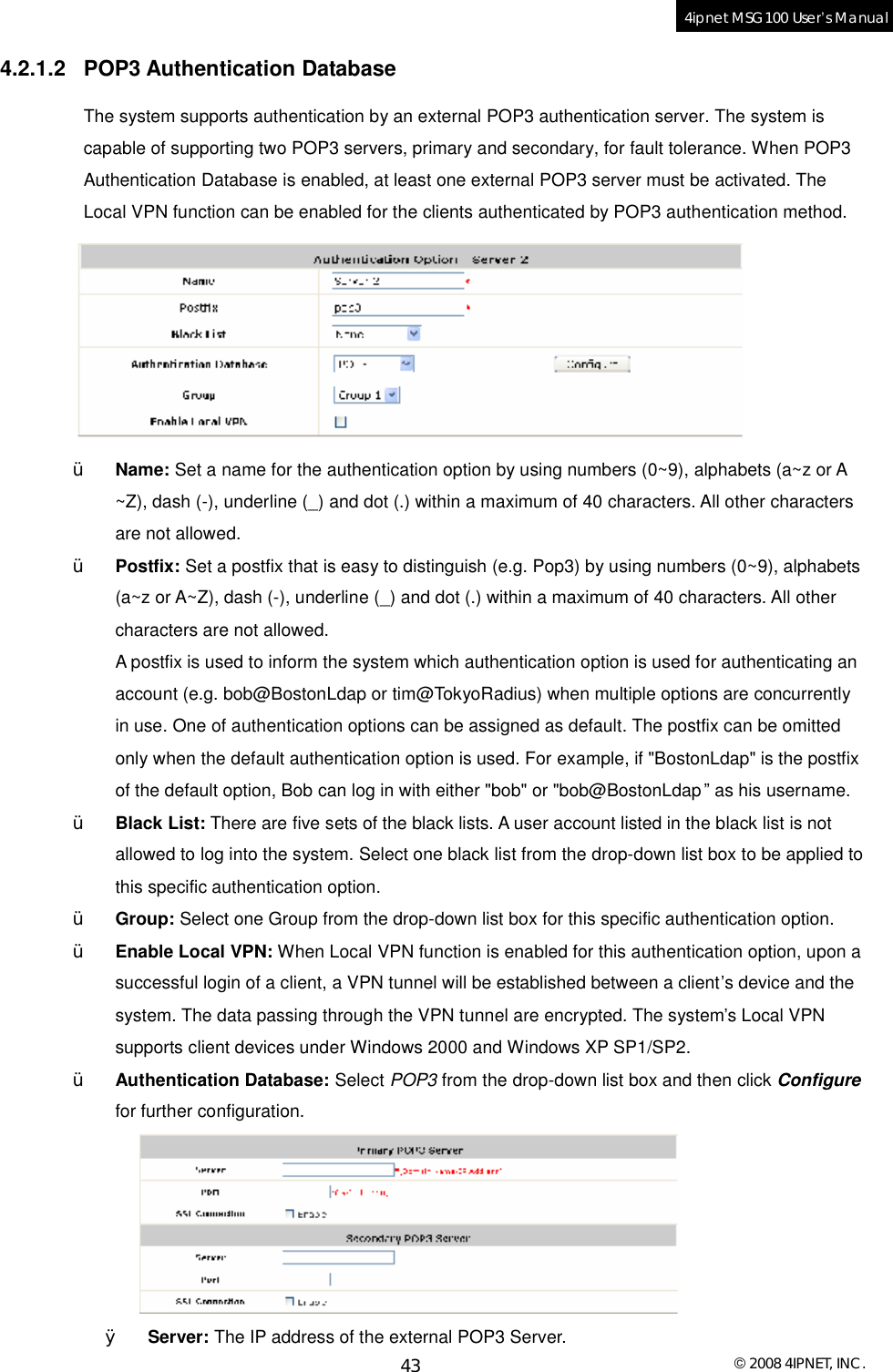
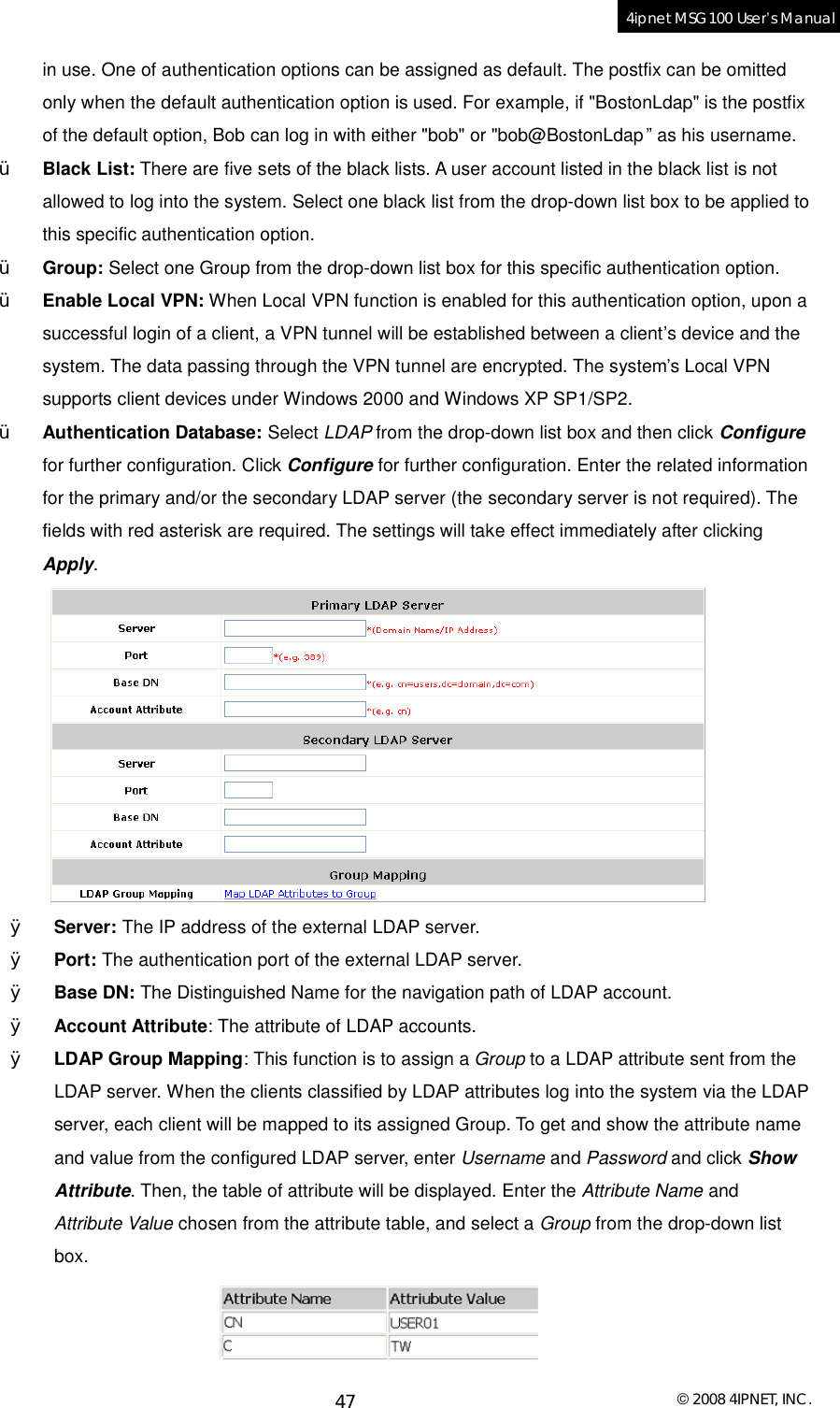
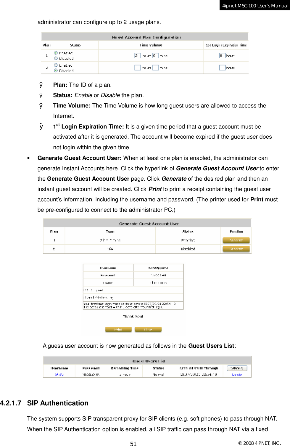
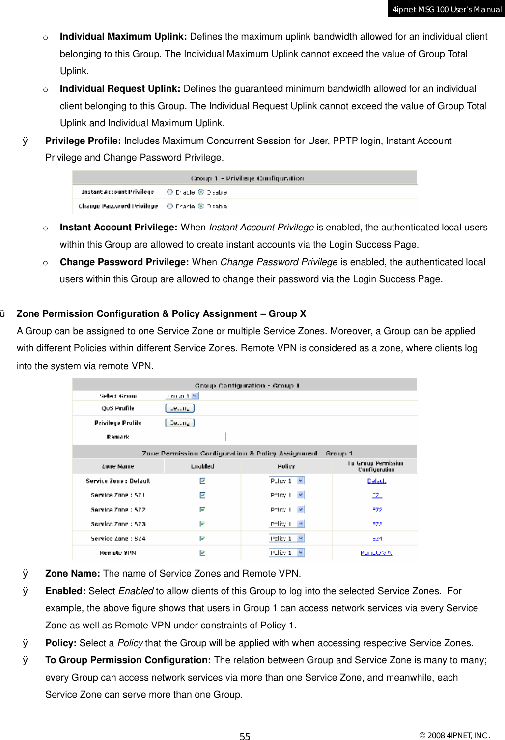
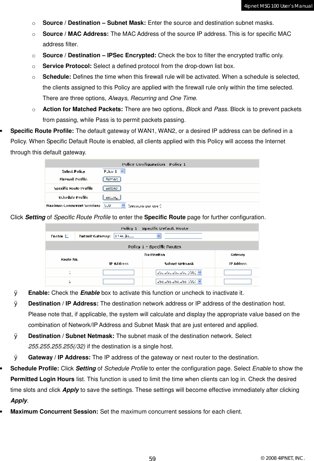
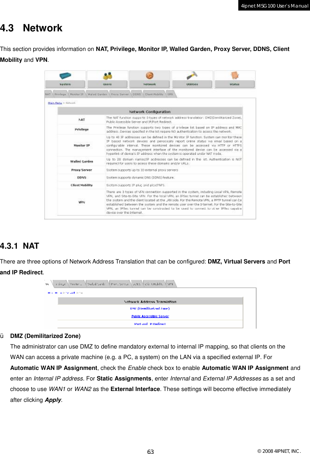
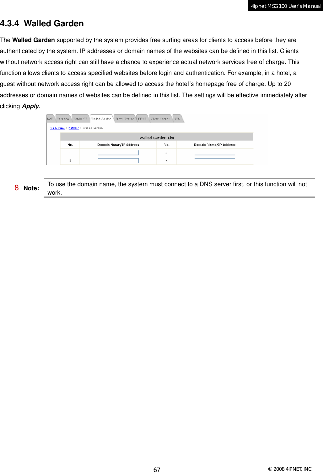
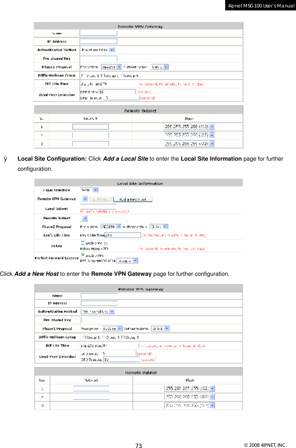
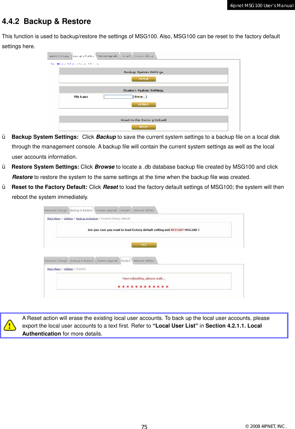
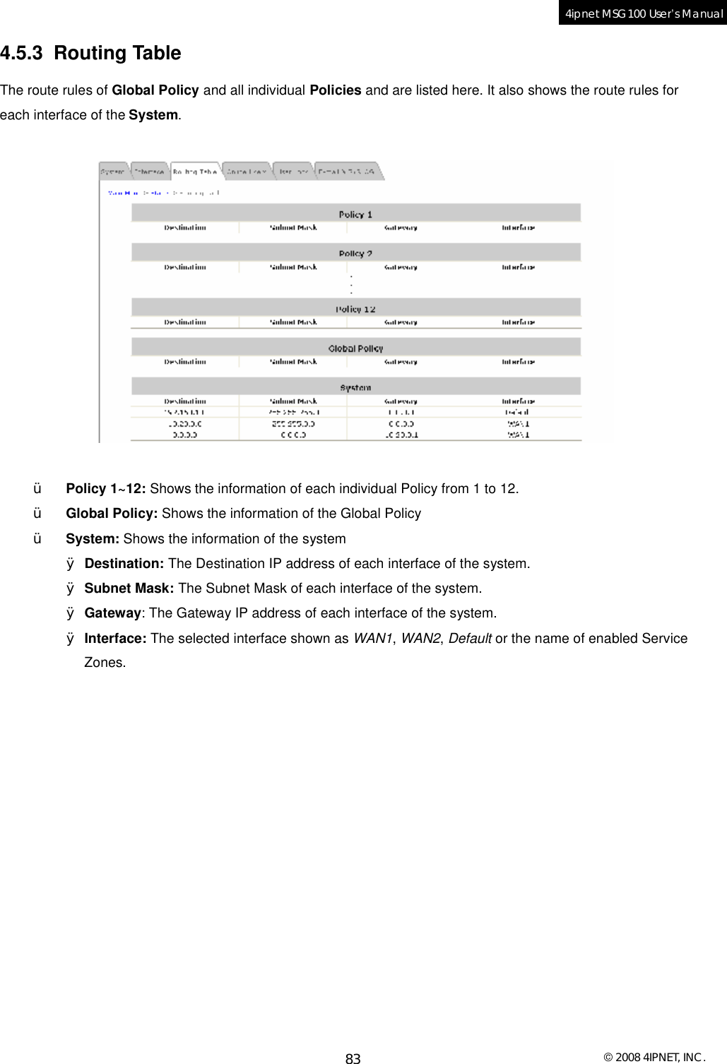
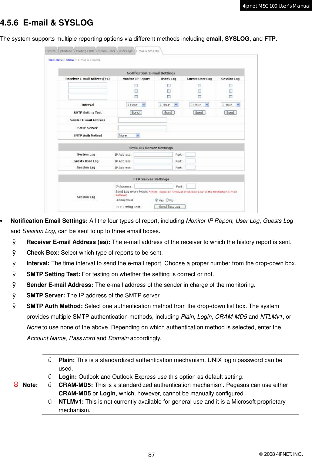
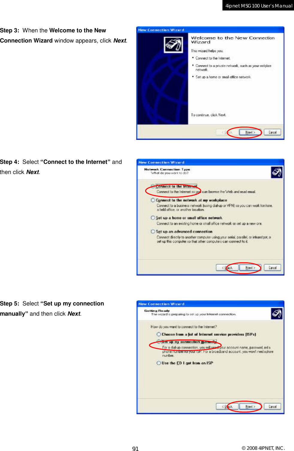
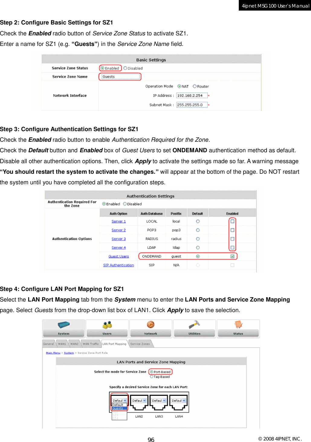
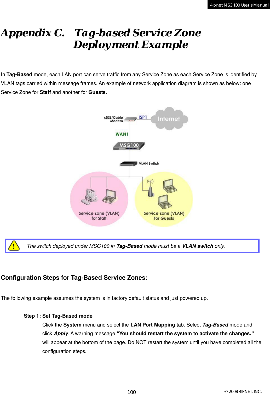
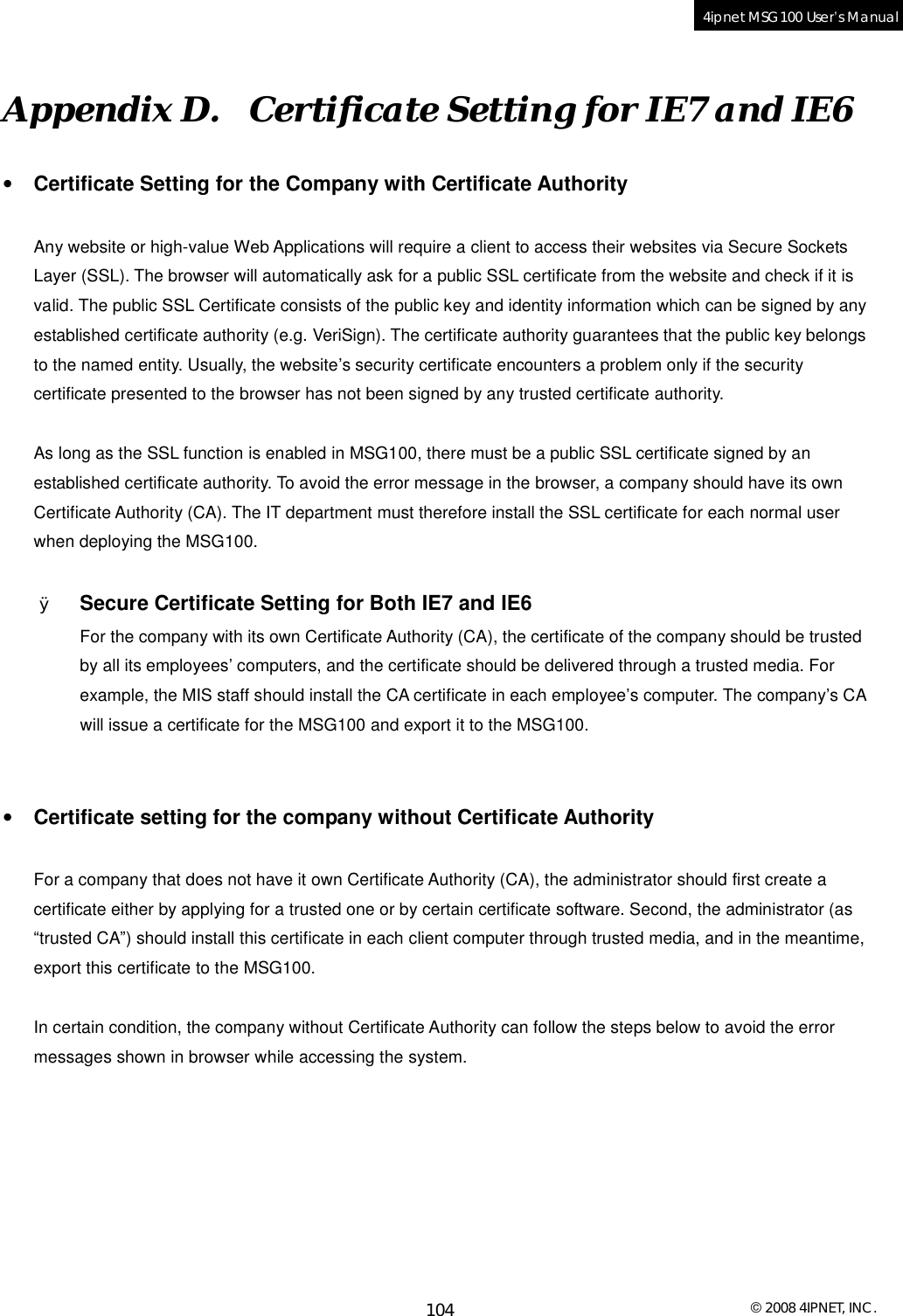
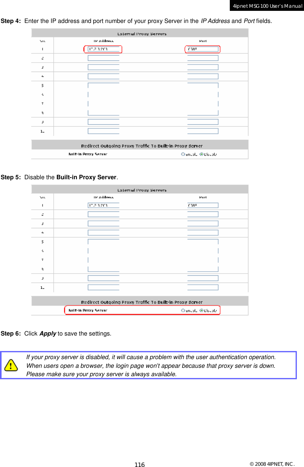
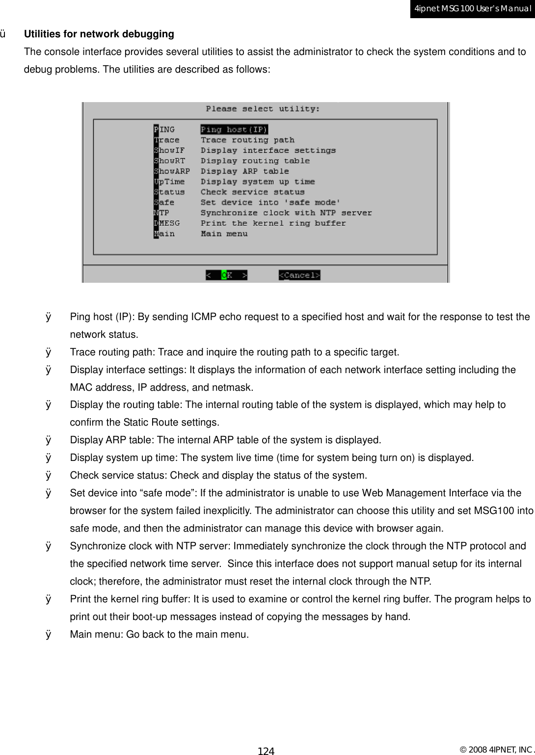
![© 2008 4IPNET, INC. 127 4ipnet MSG100 User’s Manual Ø An example of session log data is shown as below: Aug 30 12:35:05 2007 [New]user1@local TCP MAC=00:09:6b:cd:83:8c SIP=10.1.1.37 SPort=1626 DIP=203.125.164.132 DPort=80 Aug 30 12:35:05 2007 [New]user1@local TCP MAC=00:09:6b:cd:83:8c SIP=10.1.1.37 SPort=1627 DIP=203.125.164.132 DPort=80 Aug 30 12:35:06 2007 [New]user1@local TCP MAC=00:09:6b:cd:83:8c SIP=10.1.1.37 SPort=1628 DIP=203.125.164.142 DPort=80 Aug 30 12:35:06 2007 [New]user1@local TCP MAC=00:09:6b:cd:83:8c SIP=10.1.1.37 SPort=1629 DIP=203.125.164.142 DPort=80 Aug 30 12:35:07 2007 [New]user1@local TCP MAC=00:09:6b:cd:83:8c SIP=10.1.1.37 SPort=1630 DIP=67.18.163.154 DPort=80 Aug 30 12:35:09 2007 [New]user1@local TCP MAC=00:09:6b:cd:83:8c SIP=10.1.1.37 SPort=1631 DIP=202.43.195.52 DPort=80 Aug 30 12:35:10 2007 [New]user1@local TCP MAC=00:09:6b:cd:83:8c SIP=10.1.1.37 SPort=1632 DIP=203.84.196.242 DPort=80 P/N: V10020080124](https://usermanual.wiki/4IPNET/MSG100G001/User-Guide-910821-Page-130.png)