4IPNET MSG100G001 Multi Service Wireless Office Gateway User Manual manual
4IPNET, INC. Multi Service Wireless Office Gateway manual
4IPNET >
manual

4ipnet MSG100
User’s Manual
V1.00
Copyright Notice
The contents of this publication may not be reproduced in any part or as a whole, stored,
transcribed in an information retrieval system, translated into any language, or transmitted in any
form or by any means, mechanical, magnetic, electronic, optical, photocopying, manual, or
otherwise, without the prior written permission of 4IPNET, INC.
Disclaimer
4IPNET, INC. does not assume any liability arising out the application or use of any products, or software
described herein. Neither does it convey any license under its parent rights not the parent rights of others.
4IPNET further reserves the right to make changes in any products described herein without notice. The
publication is subject to change without notice.
Trademarks
4IPNET (4ipnet) is a registered trademark of 4IPNET, INC. Other trademarks mentioned in this publication
are used for identification purposes only and may be properties of their respective owners.

FCC CAUTION
This equipment has been tested and proven to comply with the limits for a class B digital device, pursuant
to part 15 of the FCC Rules. These limits are designed to provide reasonable protection against harmful
interference in a residential installation. This equipment generates uses and can radiate radio frequency
energy and, if not installed and used in accordance with the instructions, may cause harmful interference
to radio communications. However, there is no guarantee that interference will not occur in a particular
installation. If this equipment does cause harmful interference to radio or television reception, which can
be determined by turning the equipment off and on, the user is encouraged to try to correct the
interference by one or more of the following measures:
---Reorient or relocate the receiving antenna.
---Increase the separation between the equipment and receiver.
---Connect the equipment into an outlet on a circuit different from that to which the receiver is
connected.
---Consult the dealer or an experienced radio/TV technician for help.

© 2008 4IPNET, INC.
i
4ipnet
MSG
100
User
’
s
Manual
Table of Contents
1. Introduction................................................................................................................................................3
1.1 Introduction of MSG100..............................................................................................................3
1.2 System Concept..........................................................................................................................3
1.3 Document Conventions...............................................................................................................4
2. System Overview.......................................................................................................................................5
2.1 Package Contents.......................................................................................................................5
2.2 Specification................................................................................................................................5
2.2.1 Hardware Specification.......................................................................................................5
2.2.2 Technical Specification........................................................................................................6
3. Installation..................................................................................................................................................8
3.1 Panel Function Description.........................................................................................................8
3.2 Hardware Installation...................................................................................................................9
3.3 Software Configuration..............................................................................................................10
3.3.1 Instruction of Web Management Interface........................................................................10
3.3.2 Setup Wizard.....................................................................................................................13
3.3.3 User Login Portal Page.....................................................................................................16
4. Web Interface Configuration...................................................................................................................17
4.1 System Configuration................................................................................................................18
4.1 System.......................................................................................................................................18
4.1.1 General..............................................................................................................................18
4.1.2 WAN1................................................................................................................................21
4.1.3 WAN2................................................................................................................................23
4.1.4 WAN Traffic.......................................................................................................................24
4.1.5 LAN Port Mapping.............................................................................................................26
4.1.6 Service Zone.....................................................................................................................28
4.2 Users.........................................................................................................................................37
4.2.1 Authentication....................................................................................................................37
4.2.1.1 Local Authentication Database.........................................................................................38
4.2.1.2 POP3 Authentication Database........................................................................................43
4.2.1.3 RADIUS Authentication Database....................................................................................44
4.2.1.4 LDAP Authentication Database.........................................................................................46
4.2.1.5 NT Domain Authentication Database................................................................................48
4.2.1.6 ONDEMAND Authentication Database.............................................................................49
4.2.1.7 SIP Authentication.............................................................................................................51
4.2.2 Black List...........................................................................................................................53
4.2.3 Group.................................................................................................................................54

© 2008 4IPNET, INC.
ii
4ipnet
MSG
100
User
’
s
Manual
4.2.4 Policy.................................................................................................................................57
4.2.5 Additional Control..............................................................................................................60
4.3 Network......................................................................................................................................63
4.3.1 NAT....................................................................................................................................63
4.3.2 Privilege List......................................................................................................................65
4.3.3 Monitor IP..........................................................................................................................66
4.3.4 Walled Garden..................................................................................................................67
4.3.5 Proxy Server......................................................................................................................68
4.3.6 DDNS................................................................................................................................69
4.3.7 Client Mobility....................................................................................................................69
4.3.8 VPN...................................................................................................................................70
4.4 Utilities.......................................................................................................................................74
4.4.1 Password Change.............................................................................................................74
4.4.2 Backup & Restore.............................................................................................................75
4.4.3 System Upgrade...............................................................................................................76
4.4.4 Restart...............................................................................................................................76
4.4.5 Network Utilities.................................................................................................................77
4.5 Status.........................................................................................................................................79
4.5.1 System..............................................................................................................................79
4.5.2 Interface............................................................................................................................81
4.5.3 Routing Table....................................................................................................................83
4.5.4 Online Users......................................................................................................................84
4.5.5 User Logs..........................................................................................................................85
4.5.6 E-mail & SYSLOG.............................................................................................................87
4.6 Help...........................................................................................................................................89
Appendix A. Network Configuration on PC..................................................................................................90
1. Internet Connection Setup.................................................................................................................90
2. TCP/IP Network Setup.......................................................................................................................92
Appendix B. Port-based Service Zone Deployment Example....................................................................95
Appendix C. Tag-based Service Zone Deployment Example...................................................................100
Appendix D. Certificate Setting for IE7 and IE6.........................................................................................104
Appendix E. DHCP Replay............................................................................................................................112
Appendix F. Proxy Setting for Enterprise...................................................................................................114
Appendix G. IPSec VPN................................................................................................................................119
Appendix H. Console Interface....................................................................................................................123
Appendix I. Session Limit and Session Log.............................................................................................126

© 2008 4IPNET, INC.
3
4ipnet
MSG
100
User
’
s
Manual
1. Introduction
1.1 Introduction of MSG100
The 4ipnet MSG100 Multi-service Wireless Office Gateway is a “network-service-in-a-box” business gateway that
that provides remote, centralized management of data and voice services for small and branch offices and
teleworkers. The compact, multi-functional networking appliance concurrently provides advanced services,
including network segmentation, user authentication, role-based access control, and instant account provisioning
for visitors. Moreover, it provides VPN, secure WLAN, individual user bandwidth management, WAN failover and
load balancing for small businesses. Easy deployment and remote management features enable MSG100 to be
deployed in places with limited IT resource.
This manual is intended for system integrators, field engineers and network administrators to set up MSG100 in
their network environments. It contains step-by-step procedures and graphic examples to guide MIS staff or
individuals with basic network system knowledge to complete the installation.
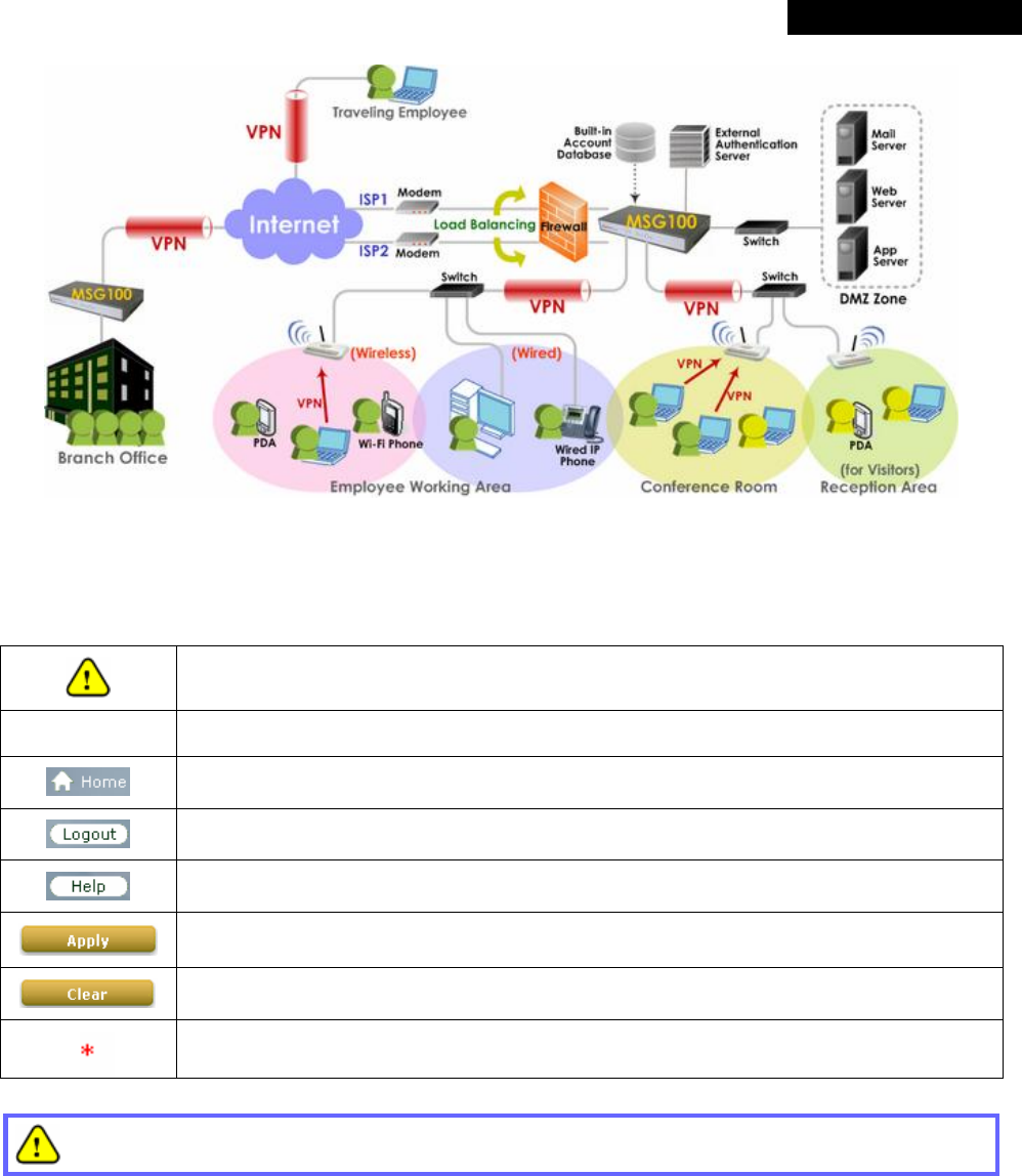
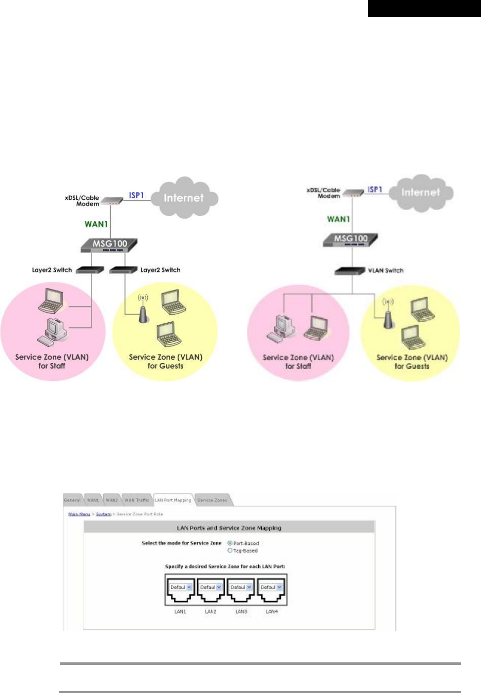
1.2 System Concept
In a Small and Mid-size Business (SMB) network environment, devices such as switches, hubs, and access points
are commonly used, and Internet connection is usually via an ADSL or a cable modem. MSG100 uses virtual LAN
(VLAN) technology to partition one physical network under its control into five logical virtual networks, called
Service Zones, including one untagged zone and four tagged zones. The untagged zone is also referred as the
Default Service Zone in this system, which is always enabled. On the other hand, the other four tagged zones can
be enabled or disabled respectively. By default, port-based configuration is used and all of the four physical LAN
ports are set to use the Default Service Zone.
The figure below demonstrates an example of the SMB network deployed with MSG100. Both LAN and WLAN of
the system can be secured by IPSec VPN. MSG100 will actively establish VPN tunnels while the selected users
are logging in. Not only the traffic within the office network will be protected by IPSec VPN, this VPN module can be
configured to support site-to-site IPSec VPN tunnels across remote branch offices. The same clientless VPN setup
implementation can also be extended to remote users in accessing office network from public Internet via PPTP
VPN tunnels. Once the remote client-to-site PPTP VPN tunnels are established, traveling employees can connect
back to the office network via reliable, secure connections using their portable devices.
© 2008 4IPNET, INC.
4
4ipnet
MSG
100
User
’
s
Manual
1.3 Document Conventions
Represents essential steps, actions, or messages that should not be ignored.
8 Note: Contains related information that corresponds to a topic.
Indicates that clicking this button will return to the system Homepage.
Logout the system.
Access Online Help interface.
Indicates that clicking this button will apply all of your settings.
Indicates that clicking this button will clear what you have set before the settings are applied.
The red asterisk indicates that information in this field is compulsory.
Screen captures and pictures used in this manual may be displayed in part or in whole, and may vary or
differ slightly from the actual product, depending on versioning and menu accessed.
© 2008 4IPNET, INC.
5
4ipnet
MSG
100
User
’
s
Manual
2. System Overview
2.1 Package Contents
The standard package of MSG100 includes:
Ÿ MSG100 x 1
Ÿ Quick Installation Guide (QIG) x 1
Ÿ CD-ROM (with User’s Manual and QIG) x 1
Ÿ Power Cord x 1
Ÿ Power Adapter (12DC, 2A) x 1
Ÿ Cross-over Ethernet RJ-45 Cable x 1
Ÿ RS-232 DB9 Console Cable x 1
It is recommended to keep the original packing material for possible future shipment when repair or
maintenance is required. Any returned product should be packed in its original packaging to prevent
damage during delivery.
2.2 Specification
2.2.1 Hardware Specification
General
† Form Factor: Mini book
† Dimensions (W x D x H): 11.8" x 6.1" x 1.7" (300 mm x 155 mm x 43 mm)
† Weight: 2.5 lbs (1.15 kg)
† Operating Temperature: 0 ~ 40 oC
† Storage Temperature: -20 ~ 65 oC
† Power Adapter: 100~240 VAC, 50/60 Hz
† Built-in real-time clock
Connectors & Display
† WAN Ports: 2 x 10BASE-T/100BASE-TX RJ-45
† LAN Ports: 4 x 10BASE-T/100BASE-TX RJ-45
† Console Port: 1 x RS-232 DB9
† LED indicators: 1 x Power, 1 x Status, 2 x WAN, 4 x LAN

© 2008 4IPNET, INC.
6
4ipnet
MSG
100
User
’
s
Manual
2.2.2 Technical Specification
Networking
† Support Router, NAT mode
† Support Static IP, DHCP, PPPoE mode on WAN interfaces and PPTP (WAN 1 only)
† Controllable LAN ports requiring authentication
† Support IP Plug and Play (IP PnP)
† Built-in DHCP server and support for DHCP relay
† Support NAT:
(1) IP/Port Destination Redirection
(2) DMZ Server Mapping
(3) Virtual Server Mapping
(4) H.323 Pass-Through
(5) SIP Pass-Through
† Support static route
† Support Wake on LAN, Web-based utilities (Ping, Trace Route and ARP) and Dynamic DNS
† Walled Garden (free surfing zone): 20
† Support MAC Address Pass-Through
† HTTP Proxy Servers: 10
† WAN failover and local balancing on dual WANs
† Support multiple Service Zones in Port-based or Tag-based mode
Security
† Local VPN tunnels to enhance wireless security: 50
† Client-to-stie remote VPN of PPTP over public Internet: 10
† Site-to-site VPN tunnels over public Internet: 3
† Support VPN Pass-Through (IPSec and PPTP)
† Support built-in DoS attack protection
† Support MAC Access Control List
† Support user Black List: 5 lists x 40 sets
† Allows MAC address and user identity binding for local user authentication
† Support QoS and WMM
User Management
† Simultaneous support for multiple authentication methods (Local, POP3(S), LDAP, RADIUS, NT
Domain, on-demand and SIP)
† Role-based access control (including Firewall policies, Specific route, Login Schedule, and Bandwidth
management)
† Support time-based firewall
† User Session Management:
(1) SSL protected login portal page
(2) Support multiple logins with one single account
(3) Session idle timer

© 2008 4IPNET, INC.
7
4ipnet
MSG
100
User
’
s
Manual
(4) Session/account expiration control
(5) Email message with a hyperlink and login reminder for accessing login page
(6) Windows domain transparent login
(7) Configurable login time frame
† Instant account (200 accounts) generation for guests by authorized users without IT’s intervention
† User account roaming support
† Support local account Grouping to classify users
System Administration
† Multi-lingual, web-based management UI
† Customizable login and logout portal pages
† SSH remote management
† Remote firmware upgrade
† NTP time synchronization
† Console management interface support (CLI)
† Backup and restore of system configuration
† SNMP v2 support
Monitoring and Reporting
† Status monitoring of on-line users
† Monitoring of IP-based network devices
† WAN connection detection and failure alert message
† Support SYSLOG for diagnosing, troubleshooting and logging
† User traffic session log
† Traffic history report in an automatic email to administrator
† Support RADIUS accounting
† Notification email of status monitoring and reporting
© 2008 4IPNET, INC.
8
4ipnet
MSG
100
User
’
s
Manual
3. Installation
3.1 Panel Function Description
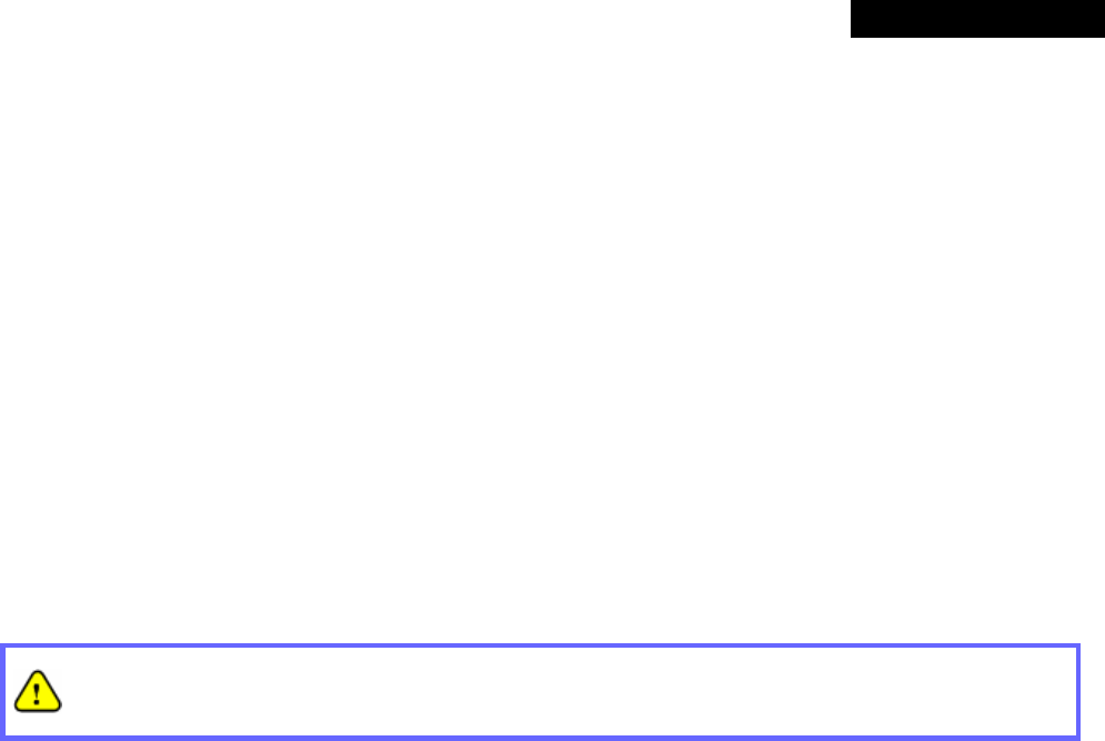
Front Panel
1. Power: ON indicates the power on, and OFF indicates the power off.
2. Status: Power and Status both ON indicate system ready, OFF indicates BIOS running, and BLINKING
indicates OS running.
3. WAN: ON indicates connection, OFF indicates no connection, and BLINKING indicates data transmitting.
4. LAN: ON indicates connection, OFF indicates no connection, and BLINKING indicates data transmitting.
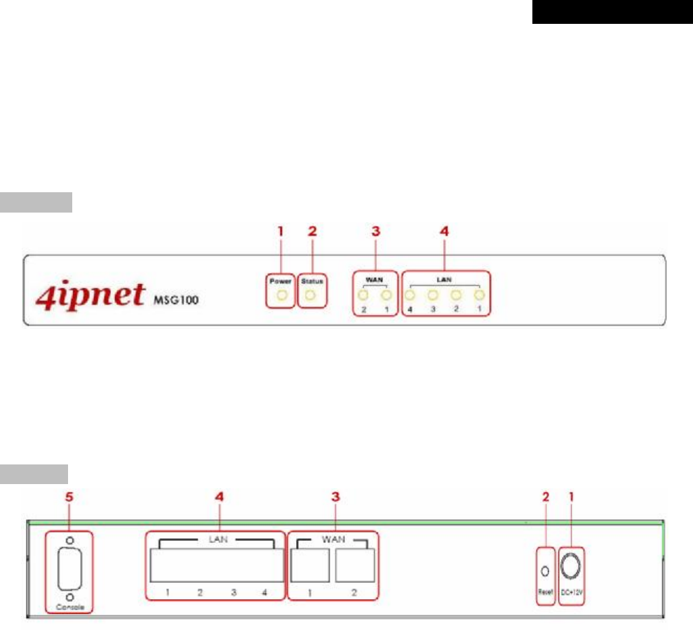
Rear Panel
1. Power: Attach the power adaptor here.
2. Reset:
• Press and hold the Reset button for about 5 seconds and the LED status indicator on the front panel
will start to blink before restarting the system.
• Press and hold the Reset button for more than 10 seconds and the LED status indicator on the front
panel will start to speed up blinking before resetting the system to default configuration.
3. WAN:
• For connecting to external networks which are not managed by MSG100 via ADSL or Cable Modem,
or connecting to a certain LAN of an organization via Switch or Hub.
4. LAN:
• For connecting to the networks managed by MSG100, such as client networking devices.
• MSG100 supports Service Zone function including Port-Based mode and Tag-Based mode. Under
Tag-Based mode, Service Zones are distinguished by VLAN tagging instead of physical LAN ports,
and vise versa. By default, the system is in Port-Based mode and all LAN ports are set to the default
Service Zone.
5. Console:For displaying text data on an extended monitor via a RS-232 DB9 cable.
© 2008 4IPNET, INC.
9
4ipnet
MSG
100
User
’
s
Manual
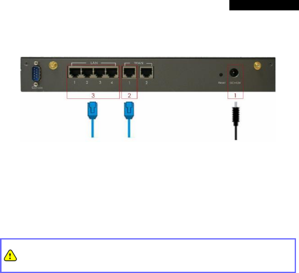
3.2 Hardware Installation
Please follow the steps mentioned below to install the hardware of MSG100.
1. Connect the power adapter to the power socket on the rear panel. The Power LED on the front panel should be
ON to indicate a proper connection.
2. Connect an Ethernet cable to WAN1 Port on the rear panel. Per your needs, connect the other end of the cable
to a networking device such as ADSL modem, cable modem, switch or hub. The WAN1 LED indicator should be
ON to indicate a proper connection.
3. Connect an Ethernet cable to any LAN Port on the rear panel. Connect the other end of the cable to a PC for
configuring the MSG100 system. The LED indicator should be ON to indicate a proper connection.
• Please only use the power adapter supplied with the MSG100 package. Using a different power
adapter may damage this system.
• To double verify the wired connection between MSG100 and your switch/router/hub, please also
check the LED status indication of these network devices.
© 2008 4IPNET, INC.
10
4ipnet
MSG
100
User
’
s
Manual
3.3 Software Configuration
3.3.1 Instruction of Web Management Interface
4ipnet MSG100 supports web-based configuration. Upon the completion of hardware installation, MSG100 can be
configured through a PC by using its web browser with JavaScript enabled such as Internet Explorer version 6.0.
Step 1:
Set DHCP in TCP/IP of the administrator PC to get an IP address dynamically. Connect the PC to any LAN Port of
MSG100. An IP address will be assigned to the PC automatically via the MSG100 built-in DHCP server.
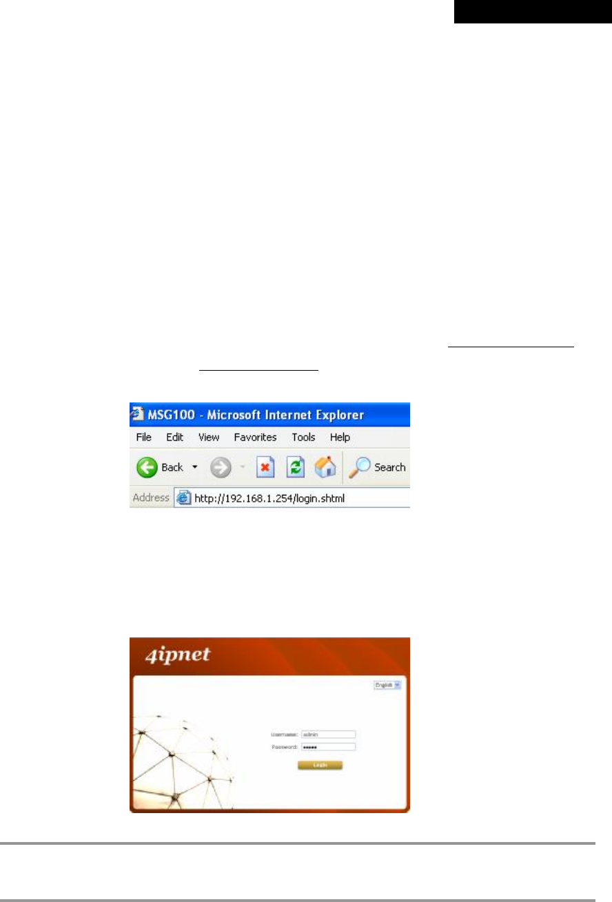
Step 2:
Launch a web browser to access the web management interface of MSG100 by entering “https://192.168.1.254”
(“https” is used for a secured connection) or “http://192.168.1.254” in the address field.
Step 3:
The following Administrator Login Page will then appear. Enter “admin” (the default value) in the Username and
Password fields, and then click Login to log in.
8 Note:
If you are unable to get to the login screen, please check the IP address used. The IP address should
be in the same subnet of the default gateway. For using static IP in TCP/IP setting, set a static IP
address such as 192.168.1.x for your network interface, and then open a new browser again.
© 2008 4IPNET, INC.
11
4ipnet
MSG
100
User
’
s
Manual
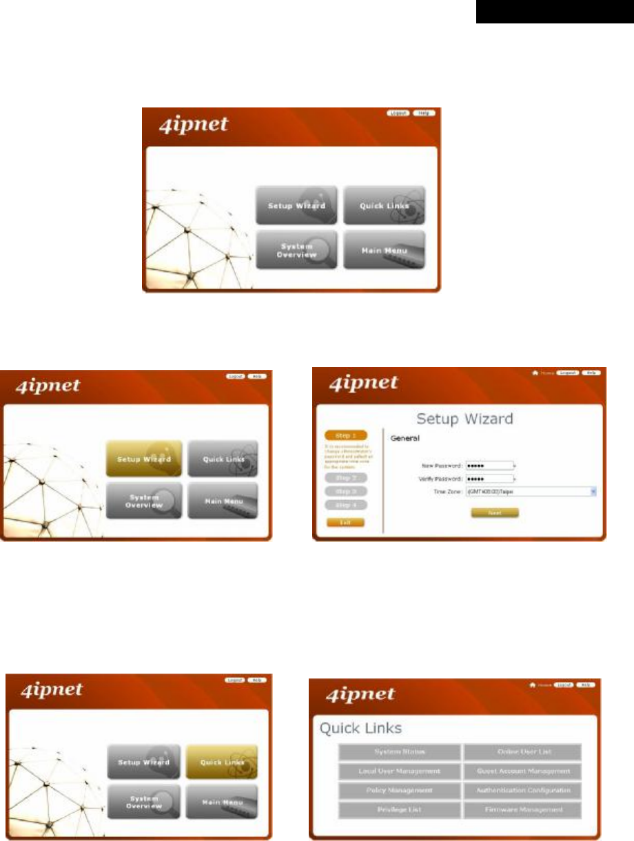
Step 4:
After a successful login, a “Home” page with four links called Setup Wizard, Quick Links, System Overview, and
Main Menu will appear.
Ø Setup Wizard: provides a four-step quick configuration of the system. Please refer to Section 3.2.2. Quick
Configuration for more information.
à
Ø Quick Links: provides 8 links for the administrator to access frequently used pages of the web management
interface directly, which are System Status, Local User Management, Policy Management, Privilege List,
Online User List, Guest Account Management, Authentication Configuration, and Firmware
Management.
à
© 2008 4IPNET, INC.
12
4ipnet
MSG
100
User
’
s
Manual
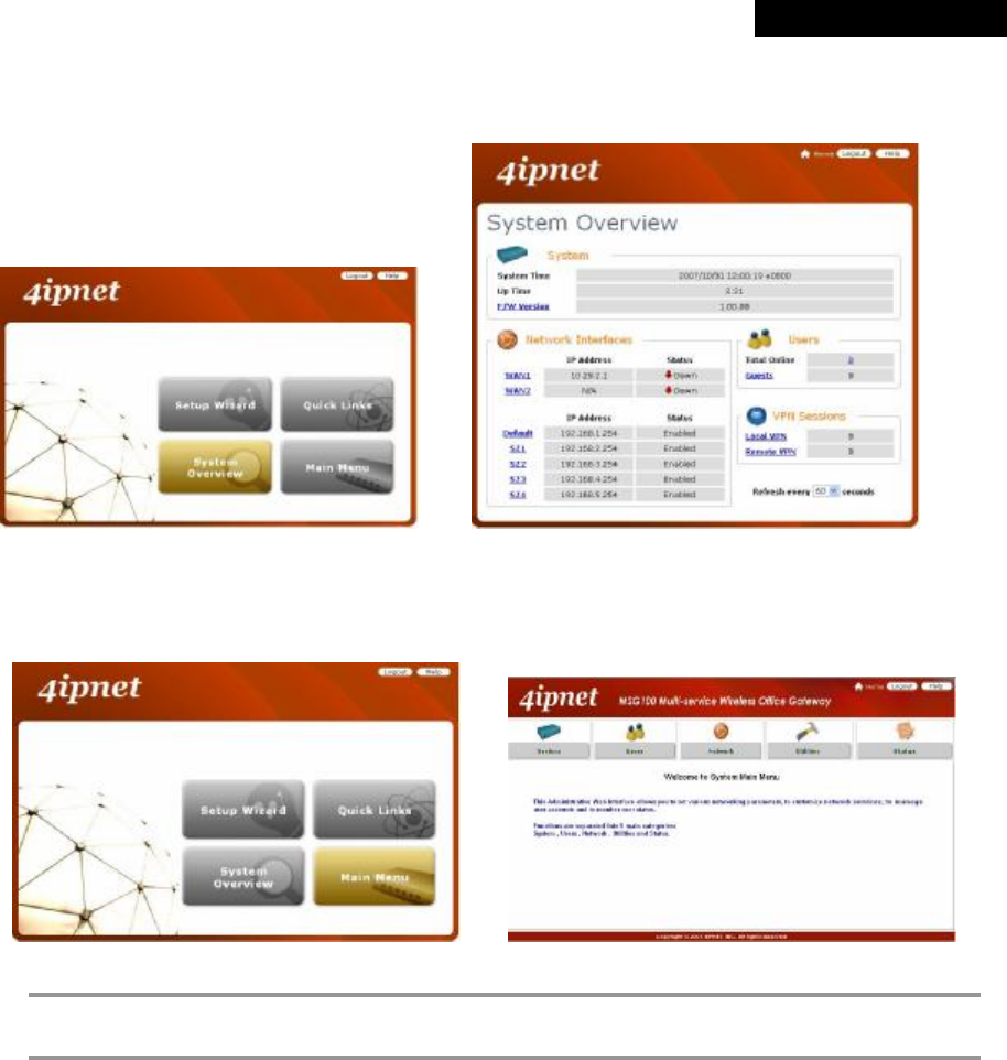
Ø System Overview: provides an overview of the system status for the administrator. Certain hyperlinks of
associated configuration pages are provided in this page for the administrator to access directly.
à
Ø Main Menu: provides detailed configuration pages for administrators to configure the system manually.
Please refer to Section 4. Main Menu for more information.
à
8 Note:
Quick Links and System Overview are not accessible until the system is configured via Setup
Wizard.
© 2008 4IPNET, INC.
13
4ipnet
MSG
100
User
’
s
Manual
3.3.2 Setup Wizard
MSG100 provides a Setup Wizard for quick configuration. The Configuration Wizard comprises of four basic steps.
Follow the instructions of Configuration Wizard to enter the required information step by step, save your settings, and
restart MSG100. Then, the system is ready to use. The four steps of Configuration Wizard are listed below:
Step I. General
Step 2. WAN1 Interface
Step 3. Local User Account (Optional)
Step 4. Confirm and Restart
Please follow the steps below to complete the Setup Wizard configuration.
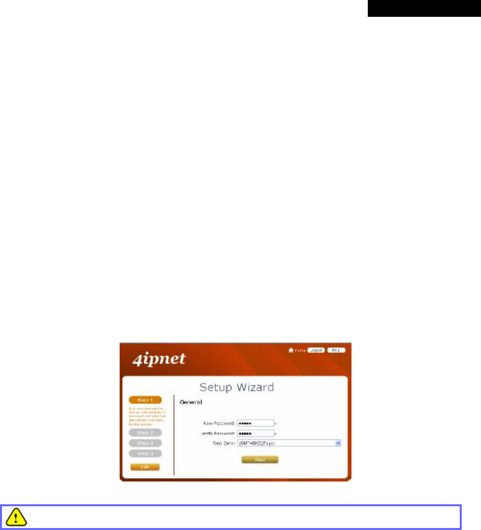
Step 1: General
• Click the Setup Wizard in the Home page to start the configuration process.
• Enter a new password in the New Password field, and re-enter it again in the Verify Password field (a maximum
of 20 characters and no spaces allowed in between).
• Select an appropriate time zone from the Time Zone drop-down list box to set up the system time.
• Click Next to continue.
For security concern, it is strongly recommended to change the administrator's password.
© 2008 4IPNET, INC.
14
4ipnet
MSG
100
User
’
s
Manual
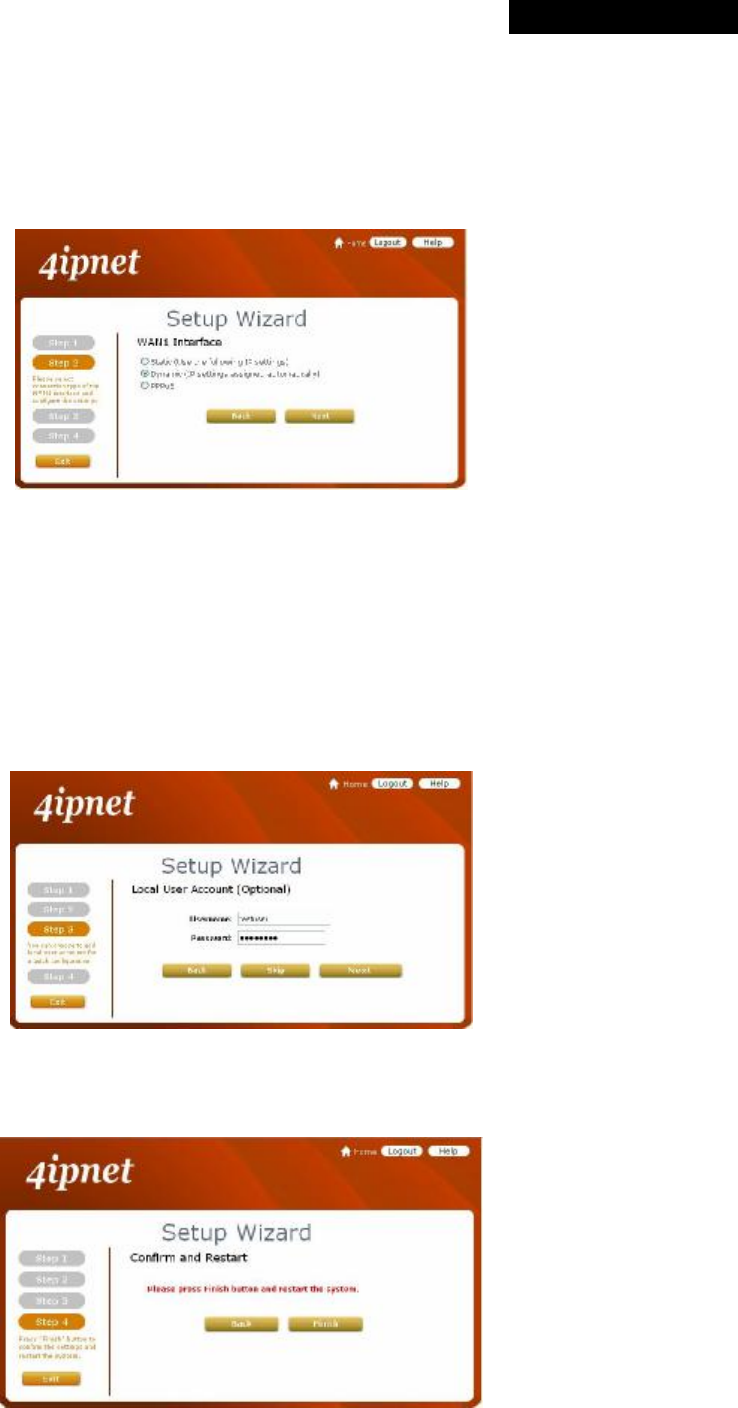
Step 2: WAN1 Interface and Wireless
• Select a proper type of Internet connection for WAN1 interface from the following three available connections:
Static, Dynamic, or PPPoE. Your ISP or network administrator can advise on the connection type available to
you. Below depicts an example for Dynamic.
• Click Next to continue.
Step 3: Local User Account (Optional)
New local accounts can be created and added into the database via this optional function. If local user accounts are
not required, click Skip to go directly to Step 4. However, it is recommended to create at least one local user account
in order to verify the system‘s readiness upon completion of this Setup Wizard.
• Enter the Username (e.g. “testuser”) and Password (e.g. “testuser”) to create a new local account.
• Click Next to continue.
• More local accounts can be added by clicking the Back button in Step 4.
Step 4: Confirm and Restart
• Click Finish to save current settings and restart the system.
© 2008 4IPNET, INC.
15
4ipnet
MSG
100
User
’
s
Manual
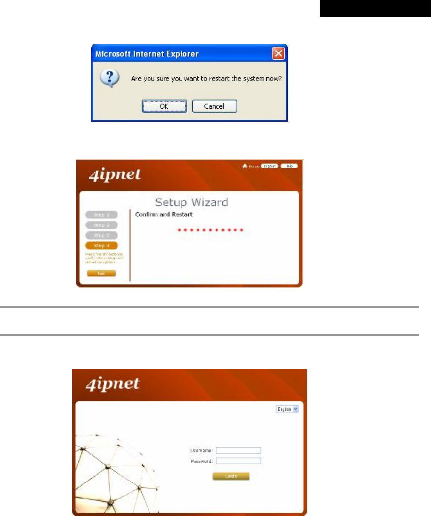
• A confirmation dialog box will then appear. Click OK to continue.
• A Confirm and Restart message will appear on the screen during the restarting process. Please do not
interrupt the system until the Administrator Login Page appears.
8 Note:
The system is trying to locate a DNS server at this stage. Therefore, a longer startup time is required
if the configured DNS cannot be found.
• When the following Administrator Login Page appears, it means the restart process is now completed.
© 2008 4IPNET, INC.
16
4ipnet
MSG
100
User
’
s
Manual
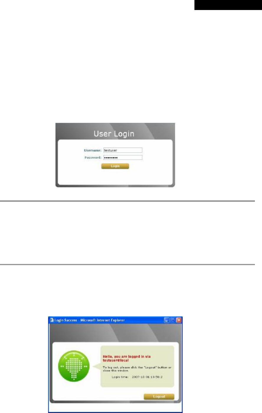
3.3.3 User Login Portal Page
In order to be granted network access via MSG100’s controlled port, a user must be authenticated first by entering a
correct username and password on the User Login Portal Page. To verify whether the configuration of the new local
user account(s) created via the Setup Wizard has been completed successfully:
1. Connect a client device (e.g. laptop, PC) to the LAN1 Port of MSG100. The device will obtain an IP address
automatically via DHCP.
2. Open a web browser on a client device, access any URL, and then the default User Login Page will appear.
3. Enter the Username and Password of a local user account previously generated via Setup Wizard (e.g.
“test@local” as the Username and “test” as the Password); then Click Login
8 Note:
1. MSG100 supports multiple authentication options including built-in local user database and
external authentication database (e.g. RADIUS). The system will automatically identify which
authentication option is used from the full username entered.
2. The format of a full (valid) username is userid@postfix, where “userid” is the user ID and
“postfix” is the name of the selected authentication option.
3. Exception: The postfix can be omitted only when the default authentication option is used. For
example, “LOCAL” is the default authentication option at this system; therefore, you may
enter either “test” or “test@local” in the Username field.
Congratulation!
The Login Success Page will appear after a client has successfully logged into MSG100 and has been authenticated
by the system. The appearance of Login Success Page means that MSG100 has been installed and configured
properly.
© 2008 4IPNET, INC.
17
4ipnet
MSG
100
User
’
s
Manual
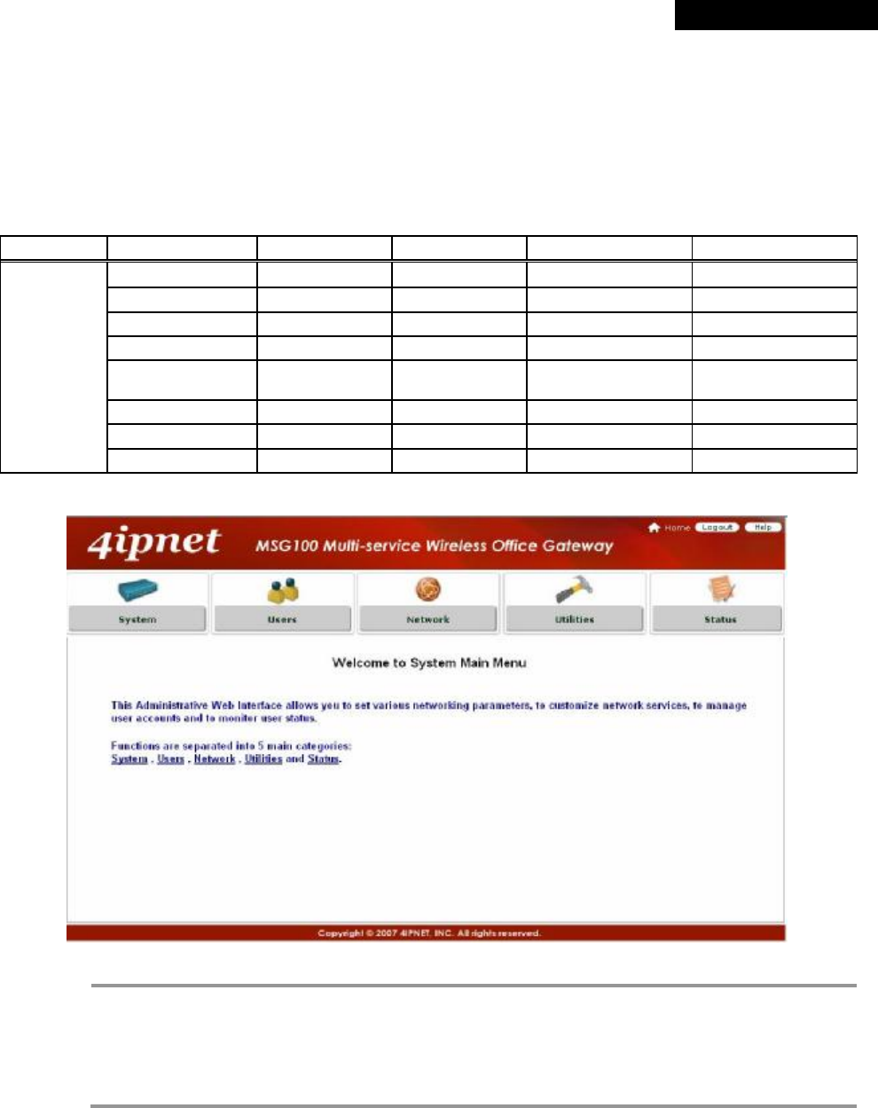
4. Web Interface Configuration
This chapter will guide you through further detailed settings. The following table shows all the UI functions of
MSG100.
OPTION System Users Network Utilities Status
General Authentication
NAT Password Change
System
WAN 1 Black List Privilege Backup & Restore
Interface
WAN 2 Group Monitor IP System Upgrade Routing Table
WAN Traffic Policy Walled Garden
Restart Online Users
LAN Port
Mapping Additional
Control Proxy Server Network Utilities User Logs
Service Zones DDNS E-mail & SYSLOG
Client Mobility
FUNCTION
VPN
8 Note:
• Click Apply to allow the changes you made on the current page to take effect immediately.
• Sometimes the system may require a restart after clicking Apply. When a restart message
appears, the system must be restarted for the settings to take effect. Restart can be done till all
configurations are completed.
• All on-line users will be disconnected during restart.
© 2008 4IPNET, INC.
18
4ipnet
MSG
100
User
’
s
Manual
4.1 System Configuration
4.1 System
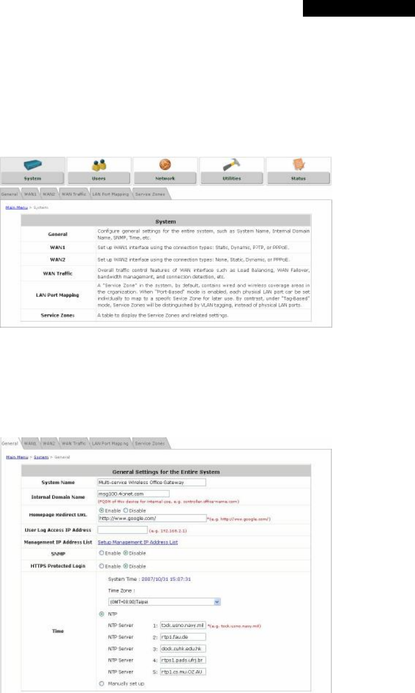
This section includes the following functions: General, WAN1, WAN2, WAN Traffic, LAN Port Mapping, and
Service Zones.
4.1.1 General
Main information about MSG100 is shown on this page, including System Name, Internal Domain Name,
Homepage Redirect URL, User Log Access IP Address, Management IP Address List, SNMP, HTTPS Protected
Login, and Network Time Protocol (NTP) Server.
© 2008 4IPNET, INC.
19
4ipnet
MSG
100
User
’
s
Manual
Ÿ System Name: Set the name of the system or use the default.
Ÿ Internal Domain Name: A fully qualified domain name (FQDN) of the system. The domain name entered here
will be shown at the top left of the Login Success page. In addition, when HTTPS is enabled, entering the
domain name of the uploaded certificate will not only change the URL of the User Login page, but also
increase login speed. For example, if the Internal Domain Name is configured as “ashop.com”, the URL of the
User Login page will be https://ashop.com/loginpages/login.shtml.
Ÿ Homepage Redirect URL: Enter the URL of a Web server as the homepage. When Local VPN is disabled at
this system, after a successful login, users will be directed to this homepage, such as http://www.google.com,
regardless of the original homepage set in their computers.
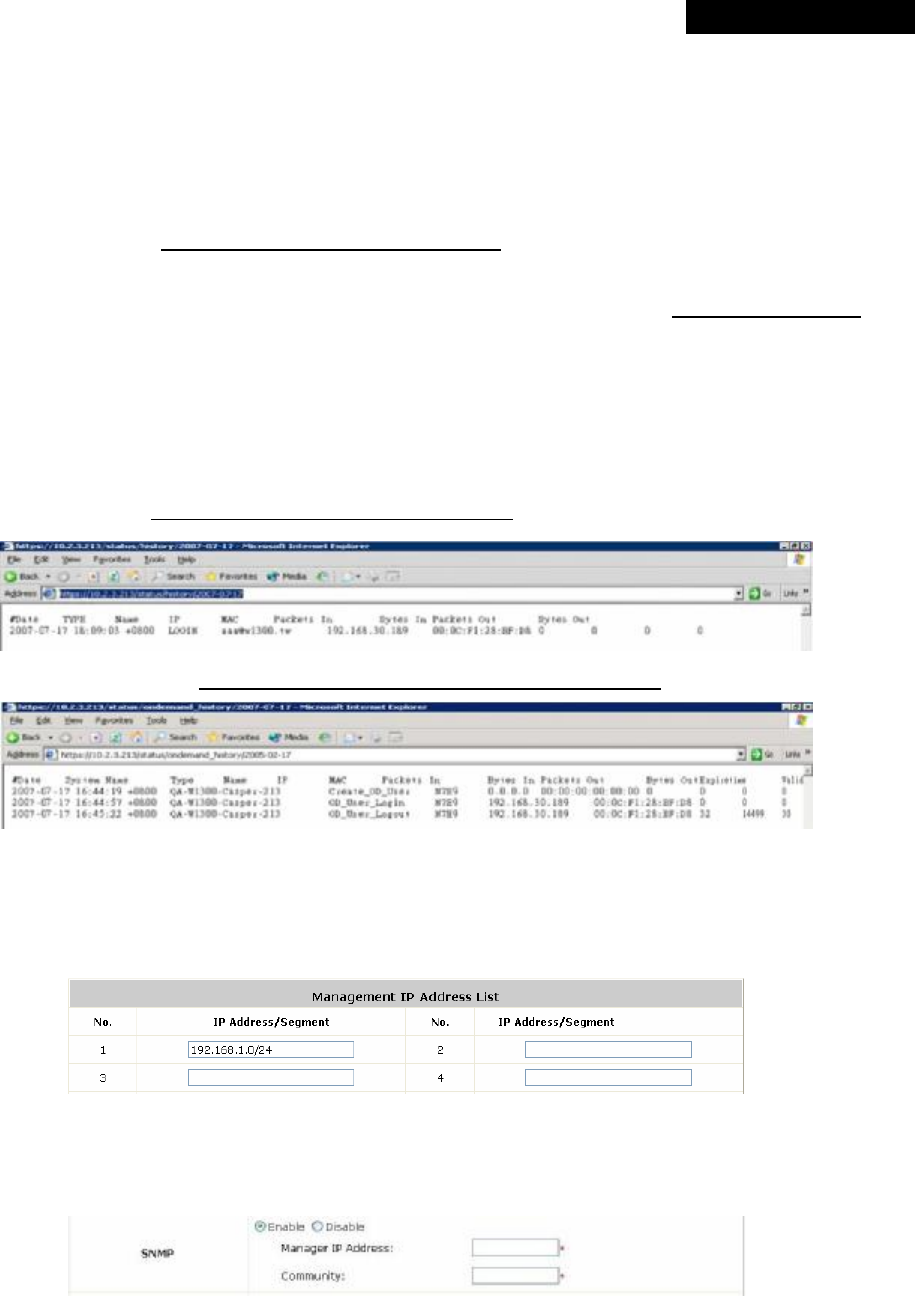
Ÿ User Log Access IP Address: Specify the IP address of an external billing system to access the system's user
logs. Only the specified billing system can directly access the system's user logs in text format via a Web
browser. For example, if the access interface of MSG100 is “10.30.1.213”, the user logs can be found in
following URLs.
n Traffic History:https://10.2.3.213/status/history/2007-07-17
n On-demand History:https://10.2.3.213/status/ondemand_history/2007-07-17
Ÿ Management IP Address List: Set the IP range where the web management interface of MSG100 can be
connected via its WAN and/or LAN ports. For example, “192.168.1.0/24” means that as long as you are within
the IP range between 192.168.1.0 and 192.168.1.255, you can reach the management interface.
Ÿ SNMP: MSG100 supports SNMPv2. If this function is enabled, the specified SNMP server can access the
Management Information Base (MIB) of the system.
© 2008 4IPNET, INC.
20
4ipnet
MSG
100
User
’
s
Manual
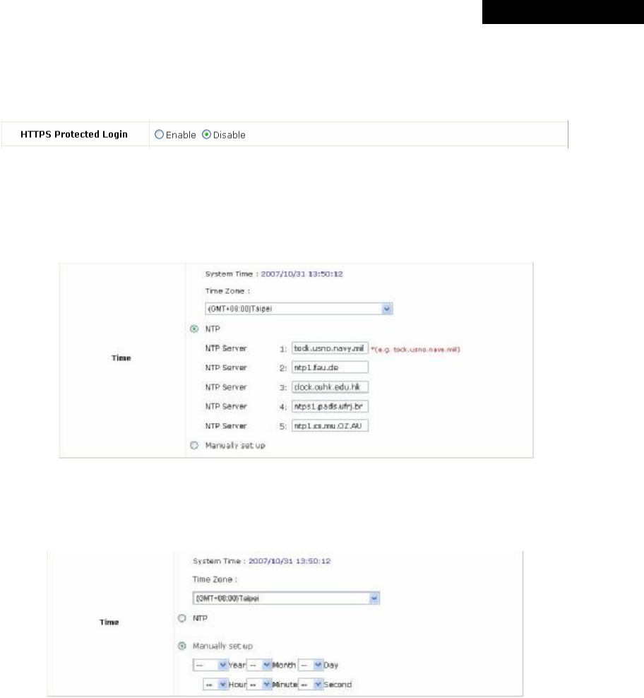
Ÿ HTTPS Protected Login: The system supports HTTPS (encrypted) and HTTP (non-encrypted) for clients to
log into the system. When this function is enabled, the Secured Socket Layer (SSL) will be activated and
implemented into the Web-based user login page.
Ÿ Time: The system time can be set up manually or synchronized with remote NTP (Network Time Protocol)
servers. It supports up to five NTP servers. When NTP is enabled, the information of at least one NTP server
must be provided.
The system time can also be set up manually by selecting Manually set up. Then select the date and time from
the drop-down list box.
© 2008 4IPNET, INC.
21
4ipnet
MSG
100
User
’
s
Manual
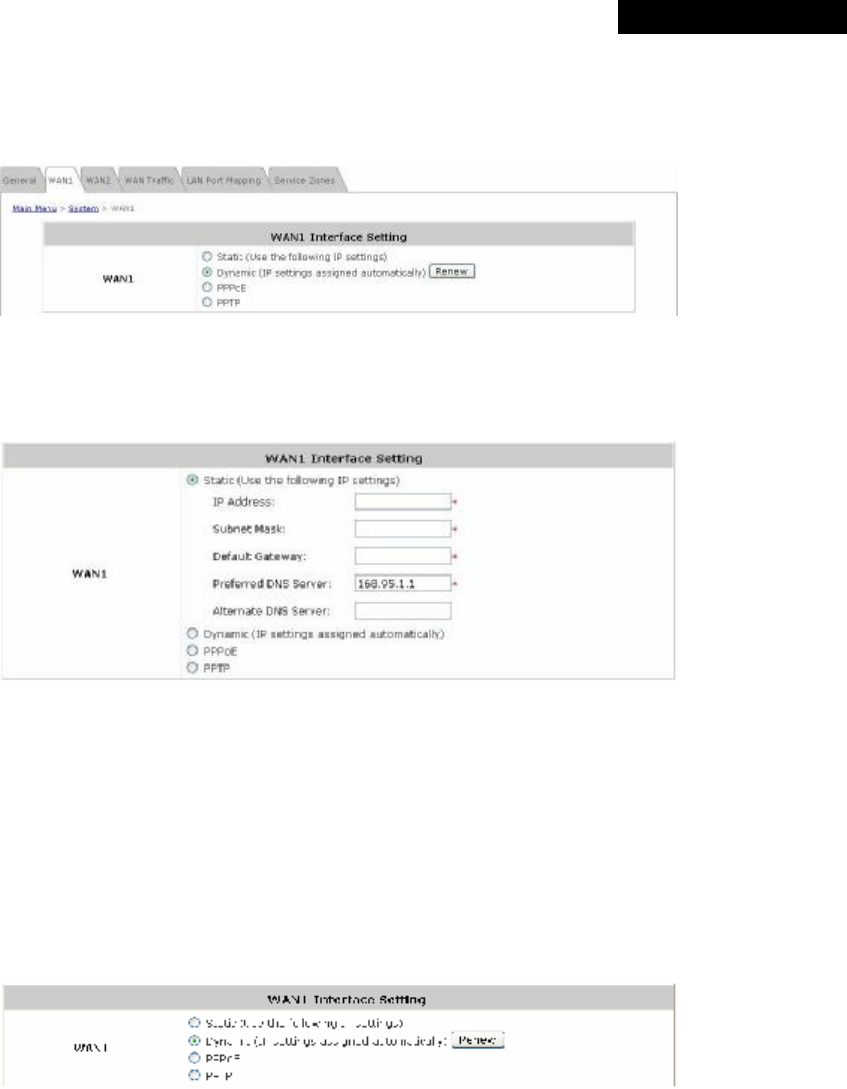
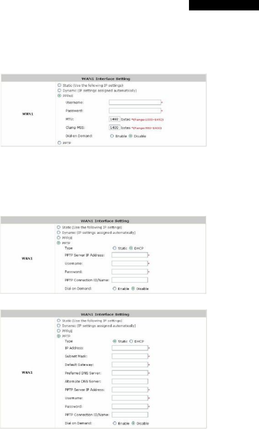
4.1.2 WAN1
There are 4 connection types supported on the WAN1 Port: Static, Dynamic, PPPoE and PPTP.
Ÿ Static (Use the following IP Settings): Select this option to specify a static IP address for the WAN1 port
manually when a static IP address is available for MSG100. The fields with red asterisk are required.
Ø IP Address: The IP address of the WAN1 port.
Ø Subnet Mask: The subnet mask of the WAN1 port.
Ø Default Gateway: The gateway of the WAN1 port.
Ø Preferred DNS Server: The primary DNS Server of the WAN1 port.
Ø Alternate DNS Server: The substitute DNS Server of the WAN1 port. This is optional.
Ÿ Dynamic (IP settings assigned automatically): This option can be selected when there is a DHCP server
located on the network that MSG100 is connected to. Click Renew to get an IP address automatically.
© 2008 4IPNET, INC.
22
4ipnet
MSG
100
User
’
s
Manual
Ÿ PPPoE: Select this option when PPPoE is the connection protocol provided by your ISP.
To properly configure PPPoE connection type, set the Username, Password, MTU and Clamp MSS.
When Dial on Demand is enabled, the Maximum Idle Time field is required to be filled in. The system will
disconnect itself from the Internet automatically when the Maximum Idle Time is reached.
Ÿ PPTP: Select this option when PPTP is the connection protocol provided by your ISP.
When Dial on Demand is enabled, the Maximum Idle Time field is required to be filled in. The system will
disconnect itself from the Internet automatically when the Maximum Idle Time is reached.
There are two connection types available, Static or DHCP.
Ø Static: Select Static to specify the IP address of the PPTP Client manually.
Ø DHCP: Select DHCP to get the IP address automatically..
© 2008 4IPNET, INC.
23
4ipnet
MSG
100
User
’
s
Manual
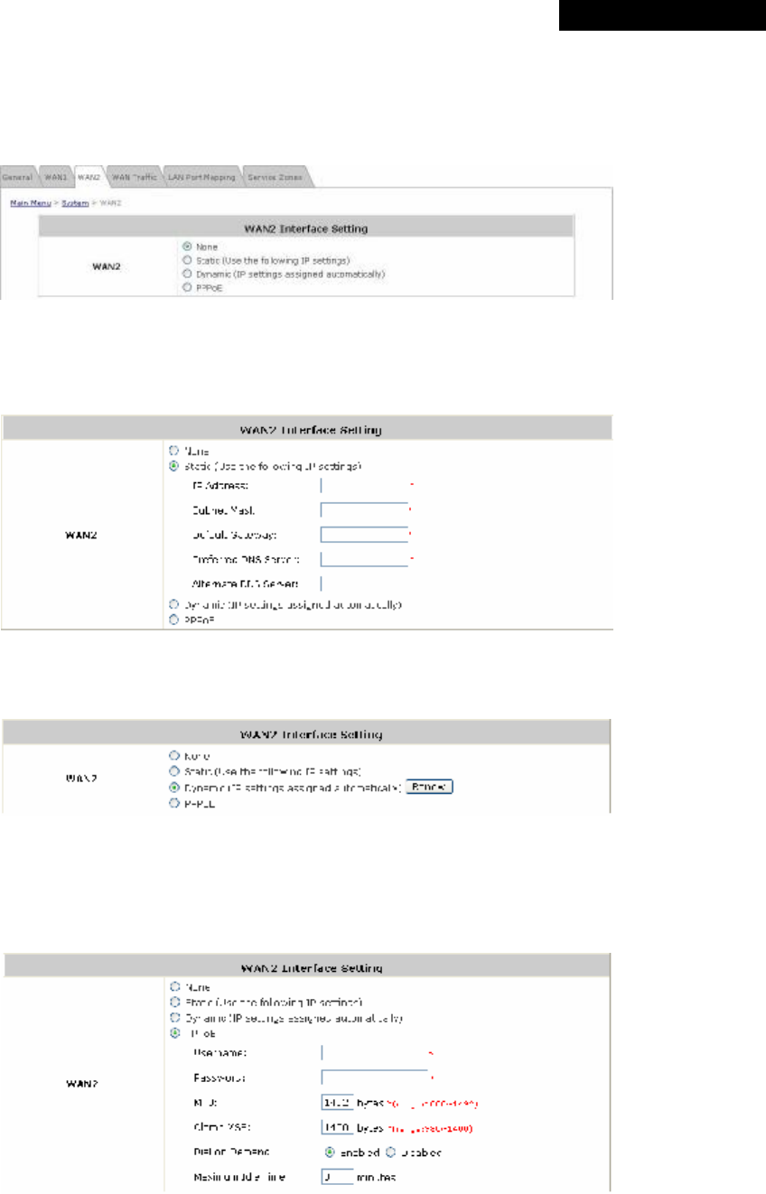
4.1.3 WAN2
WAN2 can be disabled when selecting None. When WAN2 Port is enabled, it supports 3 connection types: Static,
Dynamic and PPPoE.
Ÿ None: The WAN2 Port is disabled.
Ÿ Static (Use the following IP Settings): Select this option to specify a static IP address for the WAN2 port
manually when a static IP address is available for MSG100. The fields with red asterisk are required.
Ÿ Dynamic (IP settings assigned automatically): This option can be selected when there is a DHCP server
located on the network that MSG100 is connected to. Click Renew to get an IP address automatically.
Ÿ PPPoE: Select this option when PPPoE is the connection protocol provided by your ISP.
To properly configure PPPoE connection type, set the Username, Password, MTU and Clamp MSS.
When Dial on Demand is enabled, the Maximum Idle Time field is required to be filled in. The system will
disconnect itself from the Internet automatically when the Maximum Idle Time is reached.
© 2008 4IPNET, INC.
24
4ipnet
MSG
100
User
’
s
Manual
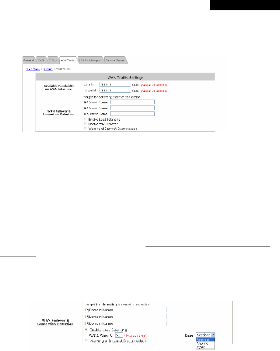
4.1.4 WAN Traffic
MSG100 supports uplink/downlink bandwidth management features, including Load Balancing and WAN Failover,
and Connection Detection.
• Available Bandwidth on WAN Interface:
Ø Uplink Bandwidth: The maximum uplink bandwidth of the WAN interface to be shared by clients. The
same setting will be applied to WAN1 and WAN2.
Ø Downlink Bandwidth: The maximum downlink bandwidth of the WAN interface to be shared by clients.
The same setting will be applied to WAN1 and WAN2.
• WAN Failover & Connection Detection: MSG100 supports WAN Failover, Load Balancing and the ability to
detect WAN connection.
Ø Target for detecting Internet connection: Enter the IP address or domain name of up to three targets to
which the system will send packets for detecting Internet connection status. If there is a problem in the
connection in the WAN port, and the specified IP address(es) or domain name(s) cannot be reached, there
will be a warning message appearing on clients’ screens. To enable WAN Failover, at least one target must
be configured.
Ø Enable Load Balancing: MSG100 supports outbound load balancing. Select to enable the system’s Load
Balancing function. The system will distribute traffics to WAN1 and WAN2 based on the weight ratio
assigned; the weight ratio can be based on Sessions, Packets or Bytes. When this function is enabled, the
WAN Failover check box will disappear because WAN Failover is covered by Load Balancing.
o WAN1 Weight: Enter a value ranging from 1~99. The default value is 50.
o Base: Three Base types can be selected from: Sessions, Packets or Bytes. Packets and Bytes are
based on historic downlink data. New connection sessions will be distributed between WAN1 and
WAN2 based on the Base selected and WAN1 Weight set.
© 2008 4IPNET, INC.
25
4ipnet
MSG
100
User
’
s
Manual
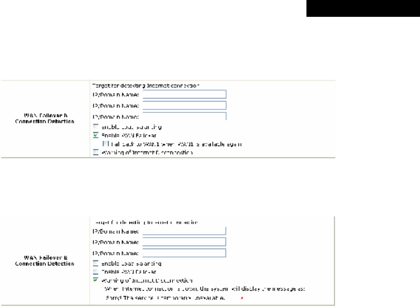
Ø Enable WAN Failover: Select to enable the WAN Failover function to ensure continuous uptime for
Internet connection. Furthermore, select “Fall back to WAN1 when WAN1 is available again” to allow the
traffic goes back to WAN1 when WAN1 becomes active again after a disconnection.
Ø Warning of Internet Disconnection: MSG100 supports Internet disconnection detection feature. When
this function is enabled, a text box will appear for the administrator to enter a warning message. This
warning message will appear on clients' screens when Internet connection is down.
© 2008 4IPNET, INC.
26
4ipnet
MSG
100
User
’
s
Manual
4.1.5 LAN Port Mapping
MSG100 supports multiple Service Zones in either of the two VLAN modes, Port-Based or Tag-Based, but not
concurrently. In Port-Base mode, each LAN port can only serve traffic from one Service Zone as each Service
Zone is identified by physical LAN ports. In Tag-Based mode, each LAN port can serve traffic from any Service
Zone as each Service Zone is identified by VLAN tags carried within message frames. By default, the system is in
Port-Based mode with Service Zone 1 (Default Service Zone) enabled and all LAN ports are mapped to Default
Service Zone. Compare two figures below to see the differences.
【Port-Based】 【Tag-Based】
It is recommended that the administrator decides which mode is better for a multiple-service-zone deployment
before proceeding further with the system configuration. Settings for the two VLAN modes are slightly different, for
example, the VLAN Tag setting is required for Tag-Based mode.
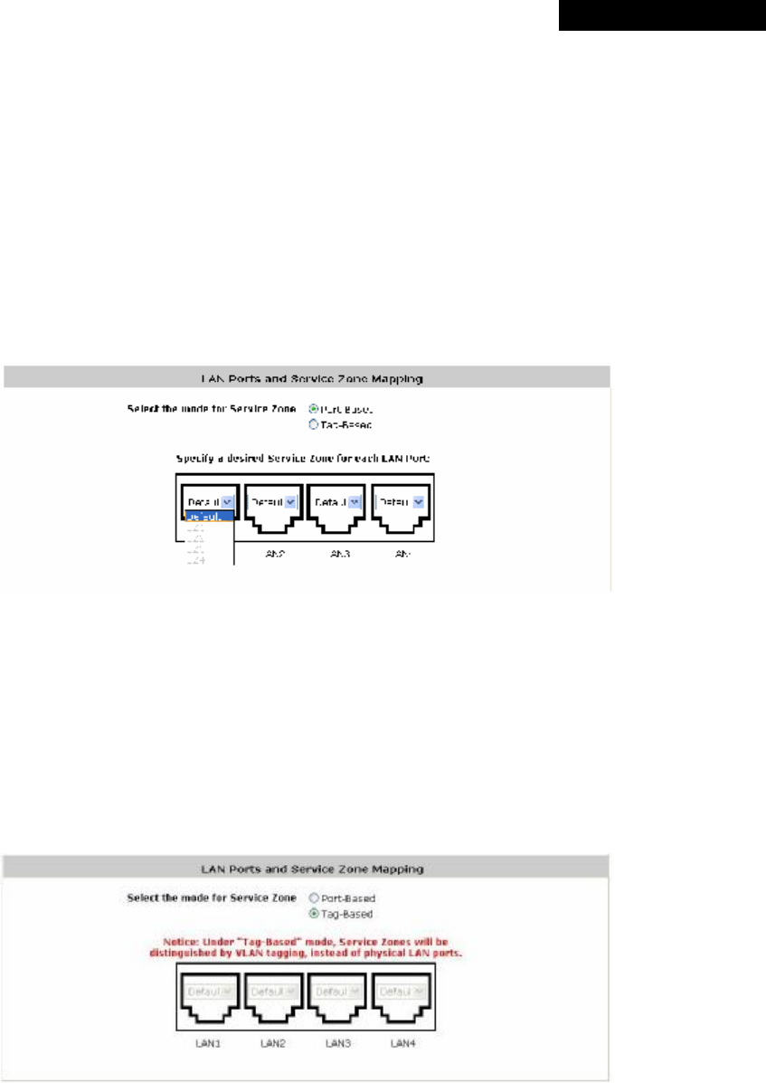
• Select the mode for Service Zone: Select a VLAN mode, either Port-Based or Tag-Based.
8 Note:
The switches deployed under MSG100 in Port-Based mode must be Layer 2 switches only.
The switch deployed under MSG100 in Tag-Based mode must be a VLAN switch only.
© 2008 4IPNET, INC.
27
4ipnet
MSG
100
User
’
s
Manual
Ø Port-Based: When Port-Based mode is selected, traffic from different virtual Service Zones will be
distinguished by physical LAN ports. Each LAN port can be mapped to a Service Zone in the form of a
many-to-one mapping between ports and Service Zones.
o Specify a desired Service Zone for each LAN Port: For each LAN port, select a Service Zone to
which the LAN port is to be mapped from the drop-down list box.
By factory default, all LAN ports are mapped to Default Service Zone; therefore, the administrator can
enter the web management interface via any LAN port upon the first power up of the system. From the
drop-down list box, all disabled Service Zones are gray-out; to activate any desired Service Zone,
please configure the desired Service Zone under the Service Zone tab and enable its Service Zone
Status (refer to Section 4.1.6. Service Zones).
Ø Tag-Based: When the Tag-Based mode is selected, traffic from different virtual Service Zones will be
distinguished by VLAN tagging, instead of by physical LAN ports.
Select Tag-Based and then click Apply to activate the Tag-Based VLAN function. When a restart
message screen appears, do NOT restart the system until you have completed the configuration under
the Service Zones tab first.
For more information on enabling Tag-Based VLAN and configuring Service Zones, please refer to
Appendix B. Service Zone – Deployment Example.
© 2008 4IPNET, INC.
28
4ipnet
MSG
100
User
’
s
Manual
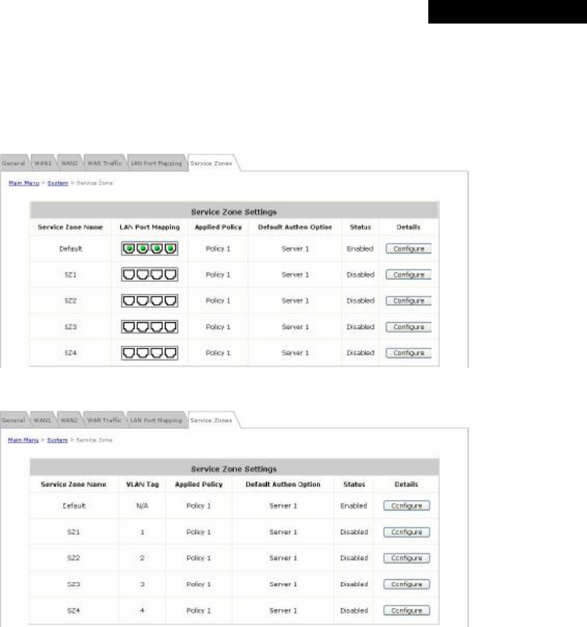
4.1.6 Service Zone
There are five Service Zones: Default, SZ1, SZ2, SZ3 and SZ4. Click Configure to complete the settings of each
Service Zone. The management interface of the Port-Based Service Zone is different from that of the Tag-Based
Service Zone
【Port-Based】
【Tag-Based】
Ÿ Service Zone Name: The name of the respective Service Zones.
Ÿ LAN Port Mapping: The Green Light indicates which physical LAN port (from left to right: LAN1, LAN2, LAN3,
and LAN4) is currently mapped to the Service Zone. This column will only appear when the system is in Port-
Based mode.
Ÿ VLAN Tag: The VLAN tag assigned to the Service Zone.
Ÿ Applied Policy: The policy applied to the Service Zone.
Ÿ Default Authentication Option: The authentication option selected for the Service Zone such as Local, POP3,
RADIUS, LDAP, NT Domain, Ondemand or SIP will be shown in this column.
Ÿ Status: Indicates whether the Service Zone is currently active or not; Enabled represents the SZ is in an active
state, and Disable represents an inactive state.
© 2008 4IPNET, INC.
29
4ipnet
MSG
100
User
’
s
Manual
Ÿ Details: Detailed settings of the Service Zone.
Click Configure to enter the Basic Settings, SIP Interface Configuration and Authentication Setting interfaces
for further configuration.
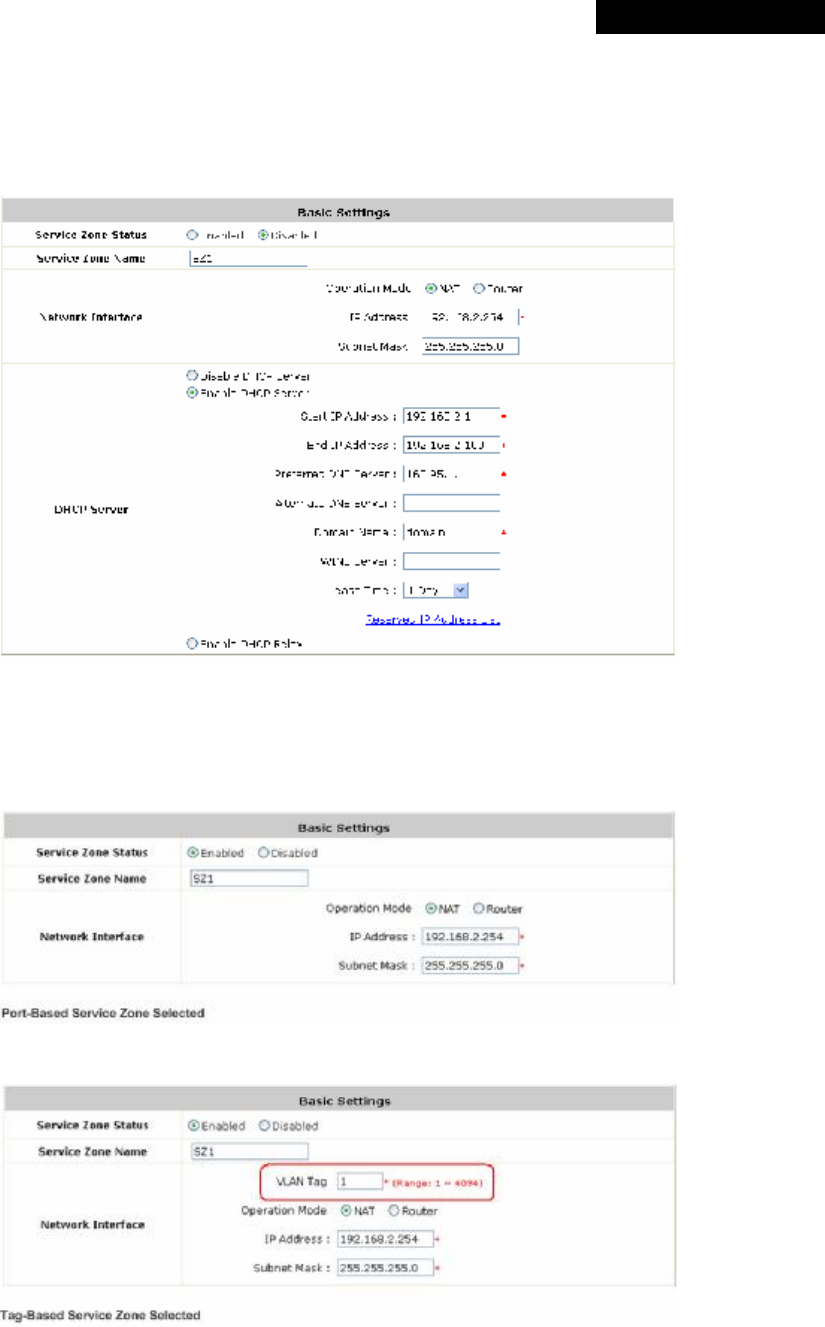
Ø Basic Settings
(1) Service Zone Status: Indicates the current activating status of the Service Zone.
(2) Service Zone Name: The name of the Service Zone.
(3) Network Interface: When the system is in Tag-Based Service Zone mode, the VLAN Tag column will
appear.
【Port-Based】
【Tag-Based】
© 2008 4IPNET, INC.
30
4ipnet
MSG
100
User
’
s
Manual
o Operation Mode: When NAT mode is selected, the Service Zone will run in NAT mode. When
Router mode is selected, the Service Zone will then run in Router mode.
o IP address: Specify the IP Address assigned to this Service Zone.
o Subnet Mask: Specify the Subnet Mask assigned to this Service Zone.
o VLAN Tag: Enter the VLAN tag number for this Service Zone.
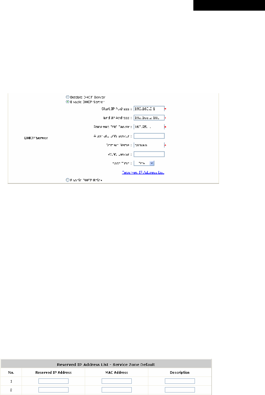
(4) DHCP Server: MSG100 supports three DHCP modes: Disable DHCP server, Enable DHCP Server or
Enable DHCP Relay. Each Service Zone can have its own DHCP setting.
o Disable DHCP Server: Select this option when using a static IP address for Internet connection.
o Enable DHCP server: The system will act as a DHCP server and assign an IP address to its clients
when this option is enabled.
▬ Start IP / End IP: Specify the range of IP addresses to be distributed by the built-in DHCP
server to clients. This setting must synchronize with the IP range configured in System >
General > Management IP Address List (refer to 4.1.1 General).
▬ Preferred DNS Server: Enter the IP address of the preferred DNS server.
▬ Alternate DNS Server: Enter the IP address of the 2nd DNS server; this is optional.
▬ Domain Name: Enter the Windows domain name for this Service Zone.
▬ WIN Server IP: The IP address of the WINS (Windows Internet Naming Service) server if a
WINS server is applicable to this Service Zone..
▬ Lease Time: The valid time period of the IP addresses issued from the DHCP server. Choose
the time interval from the drop-down list box to update DHCP IP addresses automatically.
▬ Reserved IP Address List: Each Service Zone can reserve certain IP addresses (within the
predefined DHCP range) for specific client devices via MAC, to prevent the system from
issuing these IP addresses to downstream clients.
o Enable DHCP Relay: When this option is enabled and the Service Zone is connected to an external
DHCP server, IP addresses will then be assigned by that external DHCP serve. The system will only
relay DHCP information from the external DHCP server to downstream clients of this Service Zone.
▬ DHCP Server IP Address: Enter the IP address of the external DHCP server to be used.

© 2008 4IPNET, INC.
31
4ipnet
MSG
100
User
’
s
Manual
.
For more information on DHCP replay, please refer to Appendix D. DHCP Replay.
Ø SIP Interface Configuration
The system provides SIP proxy that helps SIP clients pass through NAT. After enabling SIP and
completing SIP Authentication configuration, all authenticated SIP traffic can pass through NAT via a
selective and fixed WAN interface. (For more information on SIP Authentication configuration, refer to
4.2.1.7 SIP Authentication.)
SIP Authentication can be activated in either NAT or Router mode. A Policy can be selected to govern
SIP traffic from the clients who log in with SIP Authentication. The login schedule of the selected Policy
will be ignored by SIP Authentication. However, the specific route and firewall rules of that selected
Policy will be applied to SIP traffic.
8 Note:
Be noted that the specific route of the applied Policy cannot conflict with the assigned WAN
interface for SIP authentication.
Ø Authentication Settings
This interface displays the authentication status related to this Service Zone. Enabled means that clients
will be authenticated when accessing this Service Zone. The Login/Logout pages can also be
customized here.
© 2008 4IPNET, INC.
32
4ipnet
MSG
100
User
’
s
Manual
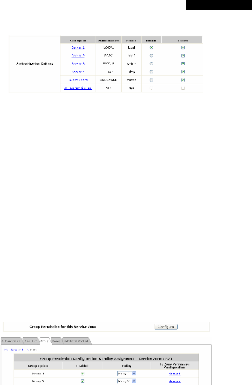
(1) Authentication Required for the Zone: Enable or disable this feature.
(2) Authentication Options:
o Auth Option: The authentication options supported by MSG100. Click the hyperlink of the
respective options, including Server1 to Server4, Guest Users, and SIP Authentication, to enter the
Authentication Option configuration page.
o Authentication Database: The type of authentication database used. The system supports five
types of authentication databases: Local, POP3, RADIUS, LDAP, and NT Domain.
o Postfix: A postfix is used to inform the system which authentication option is used for authenticating
an account (e.g. bob@BostonLdap or tim@TokyoRadius) when multiple options are concurrently in
use. One of authentication options can be assigned as default. The postfix can be omitted only when
the default authentication option is used. For example, if "BostonLdap" is the postfix of the default
option, Bob can log in with either "bob" or "bob@BostonLdap” as his username.
o Default: Select an Auth Option to be default authentication option. If clients log in the system via the
default authentication option, the postfix can be omitted when typing username.
o Enabled: Check to activate the authentication options, and uncheck to inactivate. For more
information on Authentication Methods, please refer to Section 4.2.1. Authentication.
(3) Group Permission for this Service Zone:
To configure Group permission based on the role of this Service Zone.
Click Configure to have further configuration or view the details.
Click Enabled of the desired Group option(s) to allow the clients of the selected Group(s) to log into this
Service Zone after a successful authentication. Moreover, a pre-defined Policy can be applied to any
Group in this Service Zone.
Click the hyperlink of the respective Group names in the To Zone Permission Configuration column to
enter the Group tab, where zone permission and policy assignment can be further configured (refer to
Section 4.2.3. Group).
(4) Default Policy in this Service Zone: A Policy selected from the drop-down list box can be applied to
the Service Zone. Click on Edit System Policies, the Policy Configuration interface will appear for
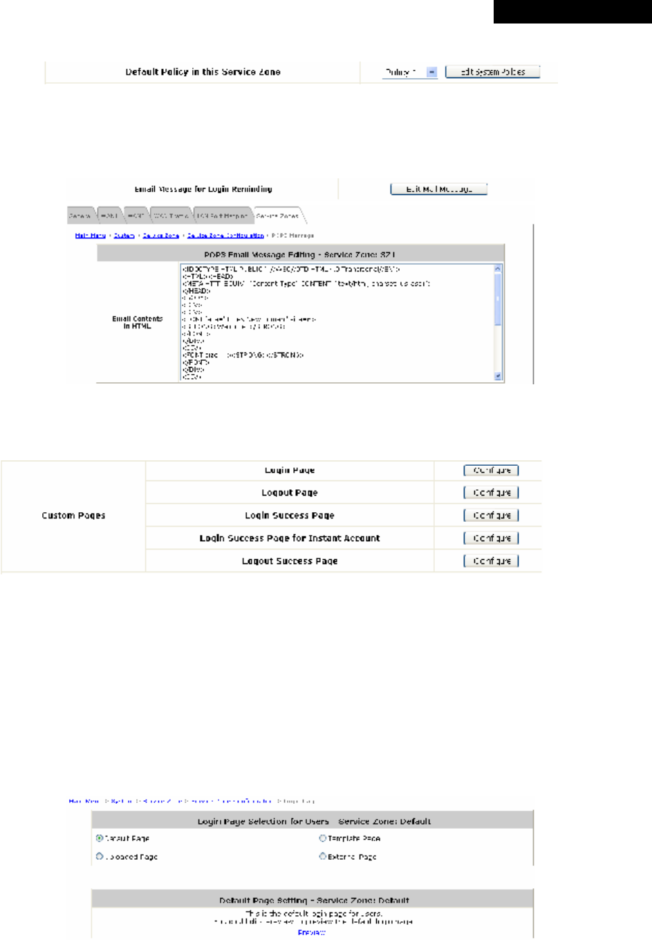
© 2008 4IPNET, INC.
33
4ipnet
MSG
100
User
’
s
Manual
detailed settings (refer to Section 4.2.4. Policy).
(5) E-mail Message for Login Reminding: The system will send an automatic POP3 e-mail to notify
clients who should have logged into the system. The administrator can customize the content of this
notification e-mail. Each Service Zone can have its own message.
Click on Edit Mail Message to enter the POP3 Email Message Editing page.
(6) Custom Pages: There are five users’ login and logout pages that can be customized by the
administrator for each Service Zone. Click Configure to have further configuration of these pages.
a. Login Page
The administrator can use the default Login Page or get the customized one by setting the template
page, uploading the page or downloading from a designated website. Upon completion of the
configuration, click Preview at the bottom of this page to view the customized Login Page. If the
administrator wishes to restore the factory default setting of Login Page, click the Use Default Page
button.
a-1. Login Page - Default Page
Choose Default Page to use the default login page.
© 2008 4IPNET, INC.
34
4ipnet
MSG
100
User
’
s
Manual
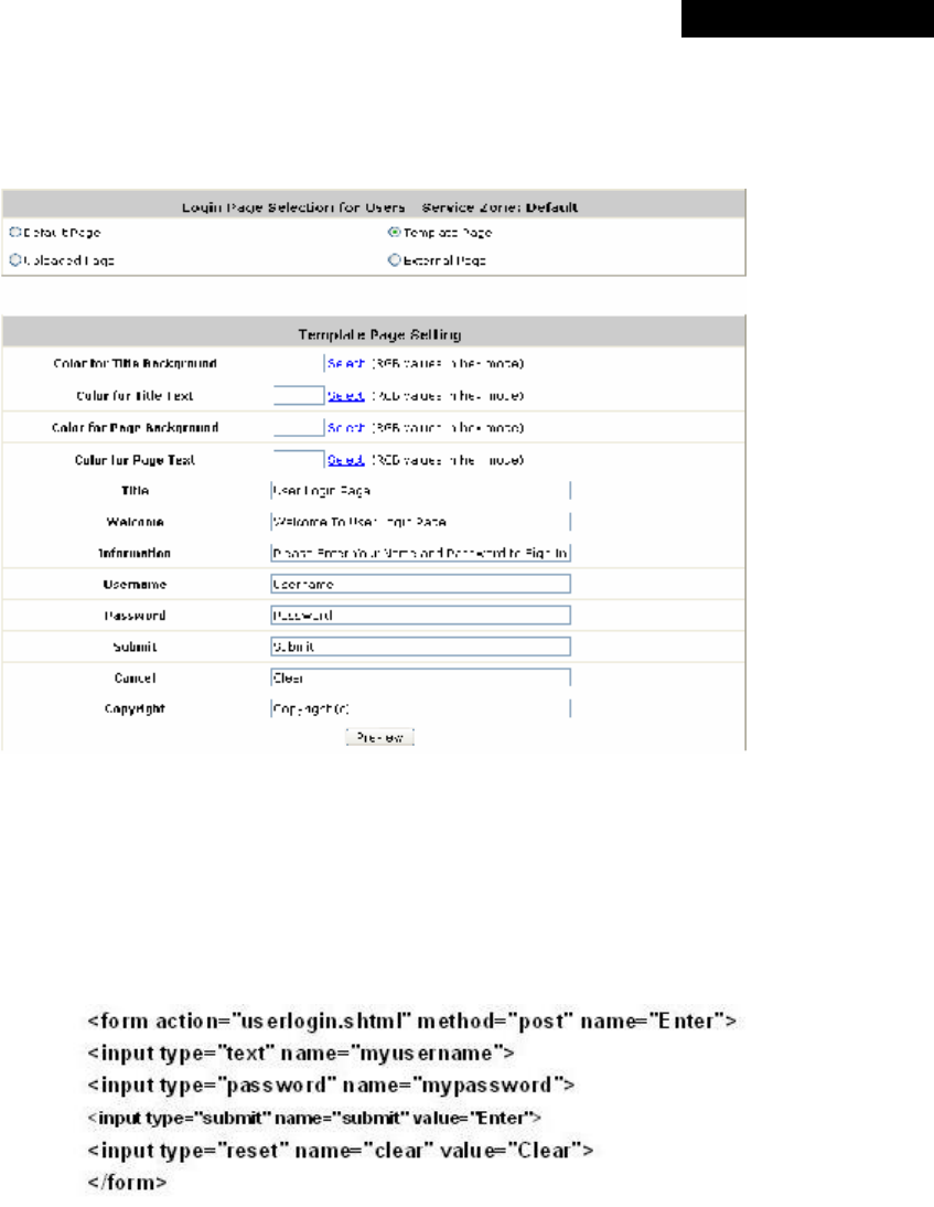
a-2. Login Page – Template Page
Choose Template Page to make a customized login page. Click the hyperlink of Select to pick a
color and then fill in all of the blanks. Click Preview to view the result first.
a-3. Login Page - Uploaded Page
Choose Uploaded Page to upload a new/edited login page.
The user-defined login page must include the following HTML codes to provide the necessary fields
for username and password.
If the user-defined login page includes an image file, the image file path in the HTML codes must
be as follows.
Remote VPN : <img src=images/xx.jpg”>
Default Service Zone : <img src=images0/xx.jpg”>
Service Zone 1 : <img src=images1/xx.jpg”>
Service Zone 2 : <img src=images2/xx.jpg”>
Service Zone 3 : <img src=images3/xx.jpg”>
Service Zone 4 : <img src=images4/xx.jpg”>
Click the Browse button to select the customized HTML codes to upload. Then click Submit to
complete the upload process.
© 2008 4IPNET, INC.
35
4ipnet
MSG
100
User
’
s
Manual
Next, enter or browse the filename of the images to be uploaded in the Upload Images field on the
Upload Images Files page and then click Submit. The system will show the used space and the
image file limit (512K).
After the image file is uploaded, the file name will show on the Existing Image Files field. Check the
file and click Delete to delete the file.
Upon the completion of the upload process, the new login page can be previewed by clicking
Preview button on the bottom.
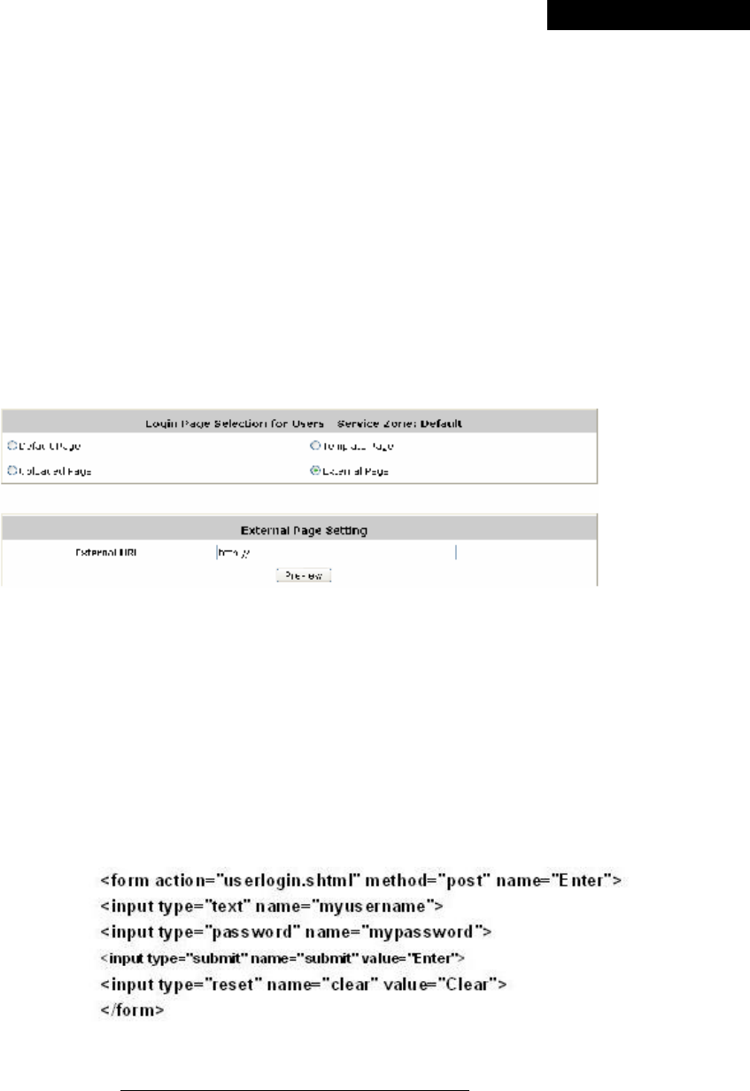
a-4. Login Pages - External Page
Choose External Page to download a login page from the designated website. Enter the website
address in the External URL field and then click Apply.
After applying the setting, the new login page can be previewed by clicking Preview at the bottom
of this page.
The user-defined login page must include the following HTML codes to provide the necessary
fields for username and password.
For example, if the system name of this MSG100 is ”abc.3322.org”, then the first line of the html
codes would be “https://abc.3322.org/loginpages/userlogin.shtml” instead of “userlogin.shtml”.
b. Logout Page
The administrator can use the default Logout Page or get the customized one by setting the
template page, uploading the page or downloading from a designated website. Upon completion of
the configuration, click Preview at the bottom of this page to view the customized Logout Page. If

© 2008 4IPNET, INC.
36
4ipnet
MSG
100
User
’
s
Manual
the administrator wishes to restore the factory default setting of Logout Page, click the Use Default
Page button. As the process is similar to that of Login Page, please refer to the configuration
instructions of Login Page for more details.
8 Note:
The HTML codes of the admin-defined logout interface are different from those of Login Page. The
following HTML codes must be included to allow users to enter the username and password.
c. Login Success Page
The administrator can use the default Login Success Page or get the customized one by
setting the template page, uploading the page or downloading from a designated website.
Upon completion of the configuration, click Preview at the bottom of this page to view the
customized Login Success Page. If the administrator wishes to restore the factory default
setting of Login Success Page, click the Use Default Page button. As the process is similar to
that of Login Page, please refer to the configuration instructions of Login Page for more
details.
d. Login Success Page for Instant Account
The administrator can use the default Login Success Page for Instant Account or get the customized
one by setting the template page, uploading the page or downloading from a designated website.
Upon completion of the setting, click Preview at the bottom of this page to view the customized
Login Success Page for Instant Account. If the administrator wishes to restore the factory default
setting of Login Success Page for Instant Account, click the Use Default Page button. As the
process is similar to that of Login Page, please refer to the configuration instructions of Login Page
for more details.
e. Logout Success Page
The administrator can use the default Logout Success Page or get the customized one by setting
the template page, uploading the page or downloading from a designated website. Upon completion
of the setting, click Preview at the bottom of this page to view the customized Logout Success Page.
If the administrator wishes to restore the factory default setting of Logout Success Page, click the
Use Default Page button. As the process is similar to that of Login Page, please refer to the
configuration instructions of Login Page for more details.
© 2008 4IPNET, INC.
37
4ipnet
MSG
100
User
’
s
Manual
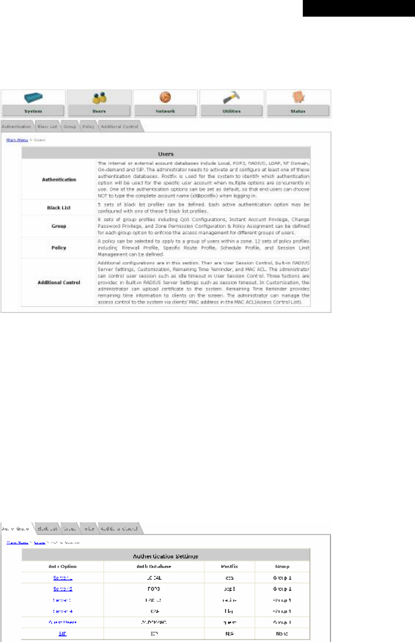
4.2 Users
This section includes the following functions: Authentication, Black List, Group, Policy and Additional Control.
4.2.1 Authentication
The function is used to configure a list of authentication options which can be enabled or disabled in the
management interface of each Service Zone. When “Authentication required for the Zone” of a Service Zone
(shown on each Service Zone’s management interface) is enabled, at least one of the authentication options must
be activated.
The system allows up to four authentication servers plus one Guest Users authentication option and SIP
authentication option. Each option ties to a user account database. The system is capable of authenticating clients
against the built-in Local authentication database and multiple external authentication servers such as POP3,
RADIUS, LDAP, and NT Domain.
Ÿ Authentication Option: The authentication options supported by MSG100. Click the hyperlink of the
respective options, including Server1 to Server4, Guest Users, and SIP Authentication, to enter the
Authentication Option configuration page.
© 2008 4IPNET, INC.
38
4ipnet
MSG
100
User
’
s
Manual
Ÿ Authentication Database: The system supports five types of authentication databases: Local, POP3, RADIUS,
LDAP, and NT Domain.
Ÿ Postfix: A postfix is used to inform the system which authentication option is used for authenticating an
account (e.g. bob@BostonLdap or tim@TokyoRadius) when multiple options are concurrently in use. One of
authentication options can be assigned as default. The postfix can be omitted only when the default
authentication option is used. For example, if "BostonLdap" is the postfix of the default option, Bob can log in
with either "bob" or "bob@BostonLdap” as his username.
8 Note:
The format of a valid username is userid@postfix, where “userid” is the user ID and “postfix” is
the name of the selected authentication option.
Ÿ Group: An authentication option, such as POP3 or NT Domain, can be set as a Group with the same QoS or
Privilege Profile setting.
For more information on Group, please refer to Section 4.2.3. Group.
Only RADIUS, POP3, and LDAP authentication databases are allowed to be enabled in more than one
Auth Option.
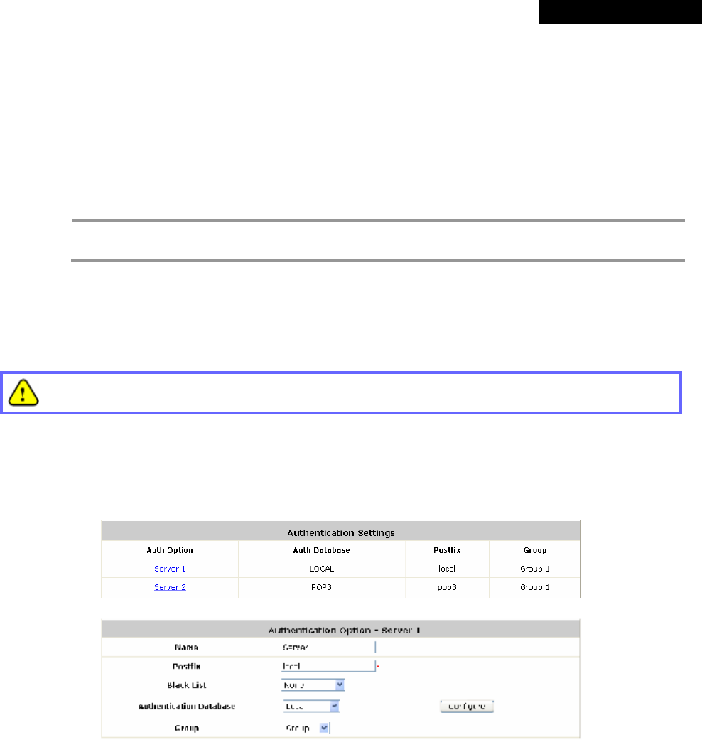
4.2.1.1 Local Authentication Database
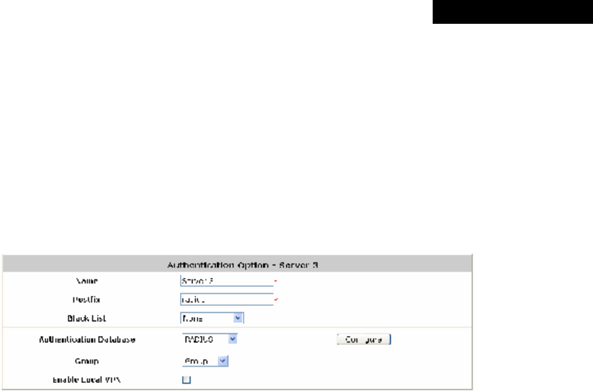
Click the hyperlink of Server 1 to enter the Authentication Option - Server 1 page.
Ÿ Name: Set a name for the authentication option by using numbers (0~9), alphabets (a~z or A
~Z), dash (-), underline (_), space and dot (.) within a maximum of 40 characters. The purpose
is that the administrator can identify the authentication options easily by their names such as
HQ-RADIUS.
Ÿ Postfix: Set a postfix that is easy to distinguish (e.g. Local) by using numbers (0~9), alphabets
(a~z or A~Z), dash (-), underline (_) and dot (.) within a maximum of 40 characters. All other
characters are not allowed.
A postfix is used to inform the system which authentication option is used for authenticating an
account (e.g. bob@BostonLdap or tim@TokyoRadius) when multiple options are concurrently
in use. One of authentication options can be assigned as default. The postfix can be omitted
only when the default authentication option is used. For example, if "BostonLdap" is the postfix
© 2008 4IPNET, INC.
39
4ipnet
MSG
100
User
’
s
Manual
of the default option, Bob can log in with either "bob" or "bob@BostonLdap” as his username.
Ÿ Black List: There are 5 sets of black lists provided by the system. A user account listed in the
black list is not allowed to log into the system. Select one black list from the drop-down list box
to be applied to this specific authentication option.
Ÿ Group: Select one Group from the drop-down list box for this specific authentication option.
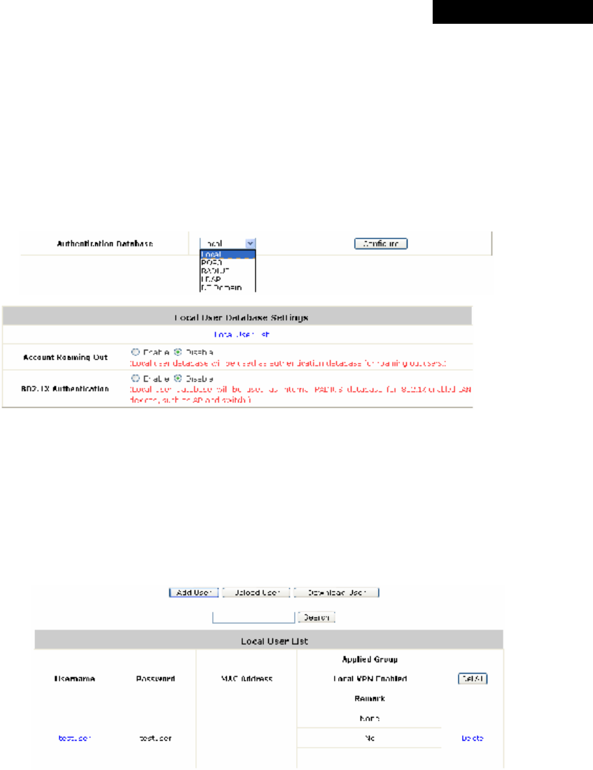
Ÿ Authentication Database: Select Local from the drop-down list box and then click Configure
to enter the Local User Database Settings.
Then, click the hyperlink of Local User List:
Ø Local User List: The administrator can view, add, and delete local user accounts here.
The Upload User button is for importing a list of user accounts from a text file. The
Download User button is for exporting all local user accounts into a text file.
Click the hyperlink of the respective usernames to enter a configuration page for further
settings. Local user accounts can be assigned to a Group and forced to apply Local VPN
respectively.
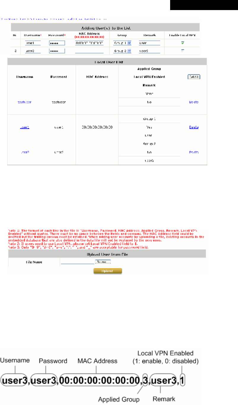
o Add User: Click this button to enter the Adding User(s) to the List interface. Then, fill in
the necessary information such as Username, Password, MAC Address (to bind the MAC
address of a networking device to a local user) and Remark. Select a desired Group to
classify local users. Check to enable Local VPN in the Enable Local VPN column. Click
Apply to complete adding the use(s).
© 2008 4IPNET, INC.
40
4ipnet
MSG
100
User
’
s
Manual
For more information on Group configuration, please refer to Section 4.2.3. Group.
o Upload User: Click Upload User to enter the Upload User from File interface. Click the
Browse button to select the text file for uploading user accounts, then click Upload to
complete the upload process.
The uploading file must be a text file and each line should contain the following information
in this specific order: Username, Password, MAC Address, Applied Group, Remark,
and Enable Local VPN. No spaces are allowed between fields and commas. The MAC
field can be omitted, but the trailing comma must be retained. When adding user accounts
by uploading a file, the existing accounts in the embedded database will be remained but
not replaced by new ones.
© 2008 4IPNET, INC.
41
4ipnet
MSG
100
User
’
s
Manual
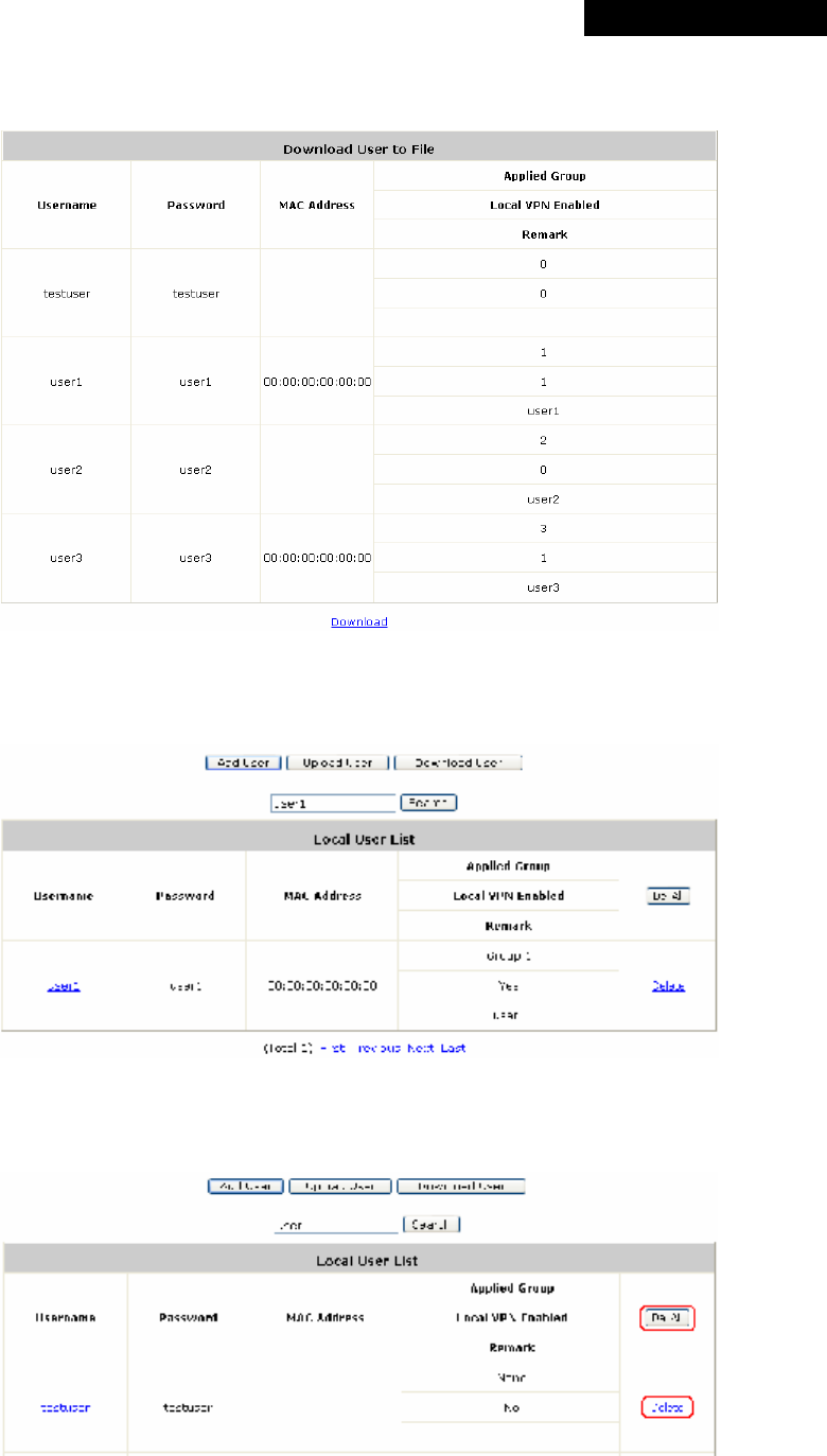
o Download User: Use this function to create a .txt file with all built-in user account
information and then save it on disk.
o Search: Enter a keyword of a username to be searched in the text filed, and click Search
to perform the search. All usernames matching the keyword will be listed.
o Del All: Click on Del All to delete all the users at once, and click on Delete to delete the
user individually.
© 2008 4IPNET, INC.
42
4ipnet
MSG
100
User
’
s
Manual
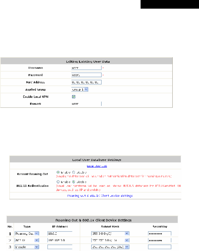
o Edit User: If editing the content of individual user account is needed, click the username of
the desired user account to enter the Editing Existing User Data Interface for that
particular user, and then modify or add any desired information such as Username,
Password, MAC Address (optional), Applied Group (optional), Enable Local VPN (optional)
and Remark (optional). Click Apply to complete the modification.
Ø Roaming Out & 802.1X Authentication: When either Account Roaming Out or
802.1X Authentication is enabled, the link of this function’s configuration page will be
available to further define authorized devices with IP Address, Subnet Mask and
Secret Key.
â
Click the hyperlink of Roaming out & 802.1X Client Device Settings to enter the
configuration interface. Choose a desired type from Disable, Roaming Out or 802.1X.
Enter the IP Address, Subnet Mask and shared Secret Key of 802.1X clients. Click
Apply to complete the settings.
▬ Account Roaming Out: MSG100’s Local Authentication Database can act as
an external RADIUS database to another authentication server. When Account
Roaming Out is enabled, local users can log into the system from other network
domains with their local user accounts on MSG100. Here, the system acts as a
RADIUS Server, and the roaming-out local users as RADIUS clients.
▬ 802.1X Authentication: When 802.1X Authentication is enabled, the Local
Authentication Database will be used as a RADIUS database for connection with
802.1X enabled devices such as access points or switches.
© 2008 4IPNET, INC.
43
4ipnet
MSG
100
User
’
s
Manual
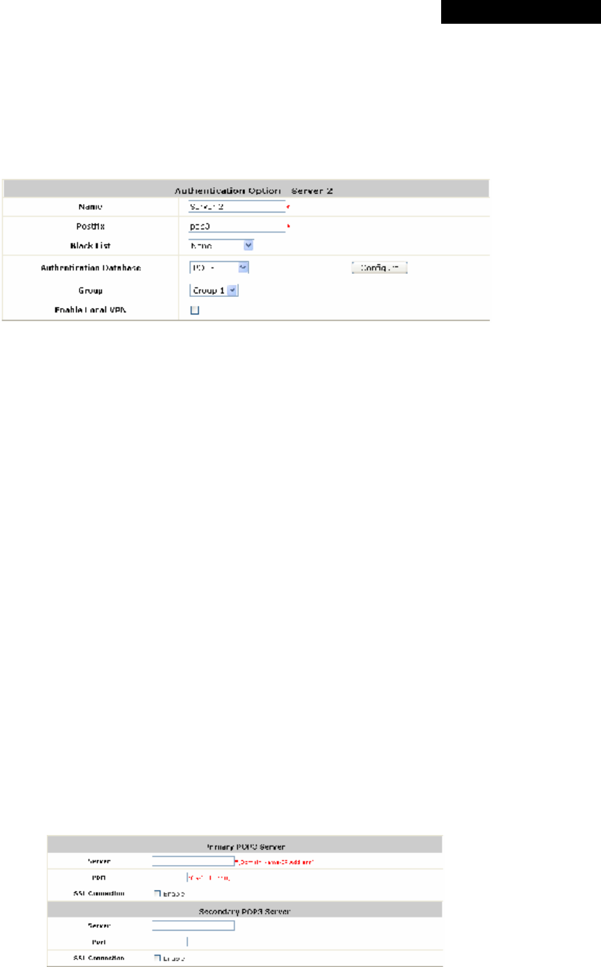
4.2.1.2 POP3 Authentication Database
The system supports authentication by an external POP3 authentication server. The system is
capable of supporting two POP3 servers, primary and secondary, for fault tolerance. When POP3
Authentication Database is enabled, at least one external POP3 server must be activated. The
Local VPN function can be enabled for the clients authenticated by POP3 authentication method.
Ÿ Name: Set a name for the authentication option by using numbers (0~9), alphabets (a~z or A
~Z), dash (-), underline (_) and dot (.) within a maximum of 40 characters. All other characters
are not allowed.
Ÿ Postfix: Set a postfix that is easy to distinguish (e.g. Pop3) by using numbers (0~9), alphabets
(a~z or A~Z), dash (-), underline (_) and dot (.) within a maximum of 40 characters. All other
characters are not allowed.
A postfix is used to inform the system which authentication option is used for authenticating an
account (e.g. bob@BostonLdap or tim@TokyoRadius) when multiple options are concurrently
in use. One of authentication options can be assigned as default. The postfix can be omitted
only when the default authentication option is used. For example, if "BostonLdap" is the postfix
of the default option, Bob can log in with either "bob" or "bob@BostonLdap” as his username.
Ÿ Black List: There are five sets of the black lists. A user account listed in the black list is not
allowed to log into the system. Select one black list from the drop-down list box to be applied to
this specific authentication option.
Ÿ Group: Select one Group from the drop-down list box for this specific authentication option.
Ÿ Enable Local VPN: When Local VPN function is enabled for this authentication option, upon a
successful login of a client, a VPN tunnel will be established between a client’s device and the
system. The data passing through the VPN tunnel are encrypted. The system’s Local VPN
supports client devices under Windows 2000 and Windows XP SP1/SP2.
Ÿ Authentication Database: Select POP3 from the drop-down list box and then click Configure
for further configuration.
Ø Server: The IP address of the external POP3 Server.
© 2008 4IPNET, INC.
44
4ipnet
MSG
100
User
’
s
Manual
Ø Port: The authentication port of the external POP3 Server.
Ø SSL Setting: The system supports POP3S. Check the Enable check box to enable
POP3S.
4.2.1.3 RADIUS Authentication Database
The system supports authentication by an external RADIUS authentication server by functioning as
a RADIUS authenticator for the RADIUS server. The system is capable of supporting two RADIUS
servers, primary and secondary, for fault tolerance.
Ÿ Name: Set a name for the authentication option by using numbers (0~9), alphabets (a~z or A
~Z), dash (-), underline (_) and dot (.) within a maximum of 40 characters. All other characters
are not allowed.
Ÿ Postfix: Set a postfix that is easy to distinguish (e.g. Radius) by using numbers (0~9),
alphabets (a~z or A~Z), dash (-), underline (_) and dot (.) within a maximum of 40 characters.
All other characters are not allowed.
A postfix is used to inform the system which authentication option is used for authenticating an
account (e.g. bob@BostonLdap or tim@TokyoRadius) when multiple options are concurrently
in use. One of authentication options can be assigned as default. The postfix can be omitted
only when the default authentication option is used. For example, if "BostonLdap" is the postfix
of the default option, Bob can log in with either "bob" or "bob@BostonLdap” as his username.
Ÿ Black List: There are five sets of the black lists. A user account listed in the black list is not
allowed to log into the system. Select one black list from the drop-down list box to be applied to
this specific authentication option.
Ÿ Group: Select one Group from the drop-down list box for this specific authentication option.
Ÿ Enable Local VPN: When Local VPN function is enabled for this authentication option, upon a
successful login of a client, a VPN tunnel will be established between a client’s device and the
system. The data passing through the VPN tunnel are encrypted. The system’s Local VPN
supports client devices under Windows 2000 and Windows XP SP1/SP2.
Ÿ Authentication Database: Select RADIUS from the drop-down list box and then click
Configure for further configuration as below. Enter the related information for the primary
and/or the secondary RADIUS server (the secondary server is not required). The fields with
red asterisk are required. The settings will take effect immediately after clicking Apply.
© 2008 4IPNET, INC.
45
4ipnet
MSG
100
User
’
s
Manual
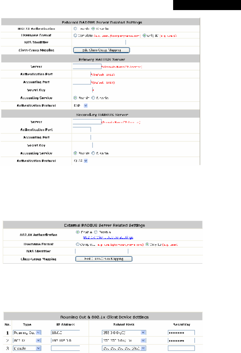
Ø 802.1X Authentication:
The system supports 802.1X. When 802.1X Authentication is enabled, the Local
Authentication Database will be used as a RADIUS database for connection with 802.1X
enabled devices such as access points or switches.
When the option is enabled, the hyperlink of 802.1X Client Device Settings will appear.
Click the hyperlink of 802.1X Client Device Settings to enter the Roaming Out and 802.1X
Client Device Settings page. Choose a desired type from Disable, Roaming Out or 802.1X.
Enter the IP Address, Subnet Mask and Secret Key of 802.1X clients. Click Apply to
complete the settings.
Ø Username Format: Select Complete to transmit both the username and postfix from the
systems’ Local Authentication Database to the external RADIUS server for user
authentication purpose, or select Only ID to transmit the username only.
Ø NAS Identifier: The Network Access Server (NAS) Identifier of the system for the external
RADIUS server.
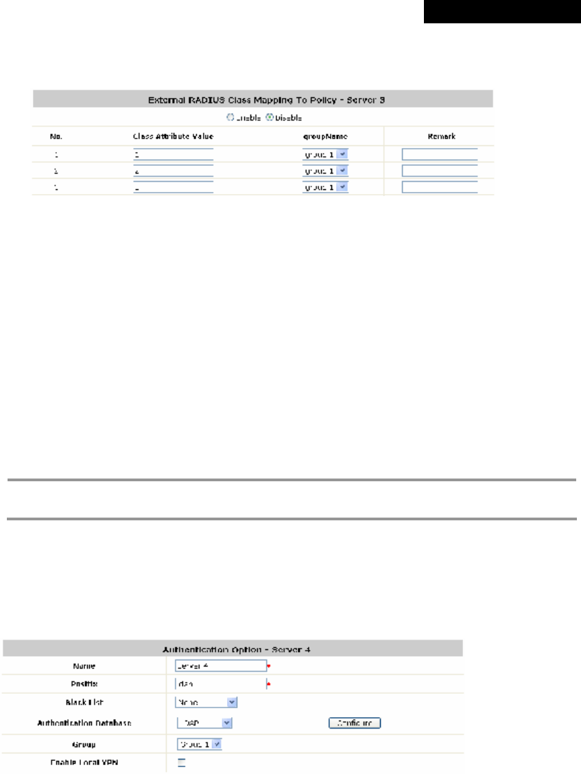
Ø Class-Group Mapping: This function is to assign a Group to a RADIUS class attribute sent
© 2008 4IPNET, INC.
46
4ipnet
MSG
100
User
’
s
Manual
from the RADIUS server. When the clients classified by RADIUS class attributes log into the
system via the RADIUS server, each client will be mapped to its assigned Group.
Ø Server: The IP address of the external RADIUS server.
Ø Authentication Port: Enter the authentication port of the RADIUS server.
Ø Accounting Port: The accounting port of the external RADIUS server.
Ø Secret Key: The Secret Key for RADIUS authentication.
Ø Accounting Service: The system supports RADIUS accounting that can be enabled or
disabled.
Ø Authentication Protocol: The configuration of the system must match with that of the
remote RADIUS server. PAP (Password Authentication Protocol) transmits passwords in plain
text without encryption. CHAP (Challenge Handshake Authentication Protocol) is a more
secure authentication protocol with hash encryption.
8 Note:
If the external RADIUS server does not assign idle-timeout value, the MSG100 will use the local
idle-timeout.
4.2.1.4 LDAP Authentication Database
The system supports authentication by an external LDAP authentication server. The system is
capable of supporting two LDAP servers, primary and secondary, for fault tolerance.
Ÿ Name: Set a name for the authentication option by using numbers (0~9), alphabets (a~z or A
~Z), dash (-), underline (_) and dot (.) within a maximum of 40 characters. All other characters
are not allowed.
Ÿ Postfix: Set a postfix that is easy to distinguish (e.g. Ldap) by using numbers (0~9), alphabets
(a~z or A~Z), dash (-), underline (_) and dot (.) within a maximum of 40 characters. All other
characters are not allowed.
A postfix is used to inform the system which authentication option is used for authenticating an
account (e.g. bob@BostonLdap or tim@TokyoRadius) when multiple options are concurrently
© 2008 4IPNET, INC.
47
4ipnet
MSG
100
User
’
s
Manual
in use. One of authentication options can be assigned as default. The postfix can be omitted
only when the default authentication option is used. For example, if "BostonLdap" is the postfix
of the default option, Bob can log in with either "bob" or "bob@BostonLdap” as his username.
Ÿ Black List: There are five sets of the black lists. A user account listed in the black list is not
allowed to log into the system. Select one black list from the drop-down list box to be applied to
this specific authentication option.
Ÿ Group: Select one Group from the drop-down list box for this specific authentication option.
Ÿ Enable Local VPN: When Local VPN function is enabled for this authentication option, upon a
successful login of a client, a VPN tunnel will be established between a client’s device and the
system. The data passing through the VPN tunnel are encrypted. The system’s Local VPN
supports client devices under Windows 2000 and Windows XP SP1/SP2.
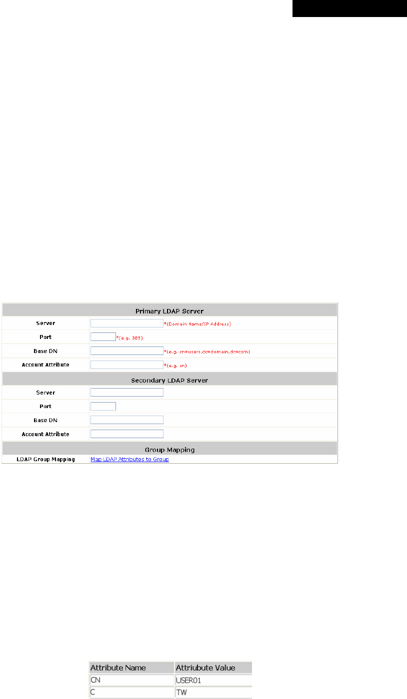
Ÿ Authentication Database: Select LDAP from the drop-down list box and then click Configure
for further configuration. Click Configure for further configuration. Enter the related information
for the primary and/or the secondary LDAP server (the secondary server is not required). The
fields with red asterisk are required. The settings will take effect immediately after clicking
Apply.
Ø Server: The IP address of the external LDAP server.
Ø Port: The authentication port of the external LDAP server.
Ø Base DN: The Distinguished Name for the navigation path of LDAP account.
Ø Account Attribute: The attribute of LDAP accounts.
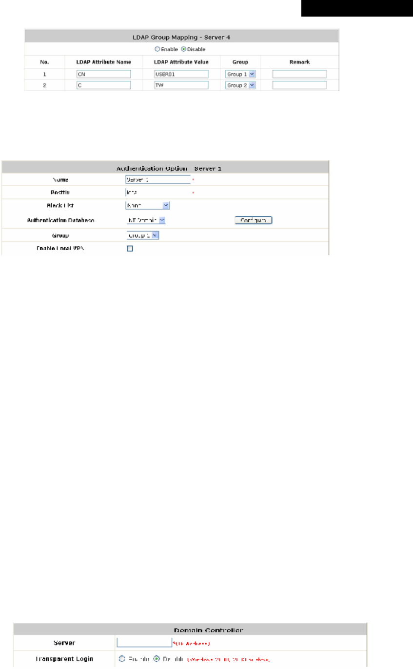
Ø LDAP Group Mapping: This function is to assign a Group to a LDAP attribute sent from the
LDAP server. When the clients classified by LDAP attributes log into the system via the LDAP
server, each client will be mapped to its assigned Group. To get and show the attribute name
and value from the configured LDAP server, enter Username and Password and click Show
Attribute. Then, the table of attribute will be displayed. Enter the Attribute Name and
Attribute Value chosen from the attribute table, and select a Group from the drop-down list
box.
© 2008 4IPNET, INC.
48
4ipnet
MSG
100
User
’
s
Manual
4.2.1.5 NT Domain Authentication Database
The system supports authentication by an external NT Domain authentication server.
Ÿ Name: Set a name for the authentication option by using numbers (0~9), alphabets (a~z or A
~Z), dash (-), underline (_) and dot (.) within a maximum of 40 characters. All other characters
are not allowed.
Ÿ Postfix: Set a postfix that is easy to distinguish (e.g. NT-Domain) by using numbers (0~9),
alphabets (a~z or A~Z), dash (-), underline (_) and dot (.) within a maximum of 40 characters.
All other characters are not allowed.
A postfix is used to inform the system which authentication option is used for authenticating an
account (e.g. bob@BostonLdap or tim@TokyoRadius) when multiple options are concurrently
in use. One of authentication options can be assigned as default. The postfix can be omitted
only when the default authentication option is used. For example, if "BostonLdap" is the postfix
of the default option, Bob can log in with either "bob" or "bob@BostonLdap” as his username.
Ÿ Black List: There are five sets of the black lists. A user account listed in the black list is not
allowed to log into the system. Select one black list from the drop-down list box to be applied to
this specific authentication option.
Ÿ Group: Select one Group from the drop-down list box for this specific authentication option.
Ÿ Enable Local VPN: When Local VPN function is enabled for this authentication option, upon a
successful login of a client, a VPN tunnel will be established between a client’s device and the
system. The data passing through the VPN tunnel are encrypted. The system’s Local VPN
supports client devices under Windows 2000 and Windows XP SP1/SP2.
Ÿ Authentication Database: Select NT Domain from the drop-down list box and click Configure
to enter the Domain Controller page. The settings will take effect immediately after clicking
Apply.
Ø Server: The IP address of the external NT Domain Server.
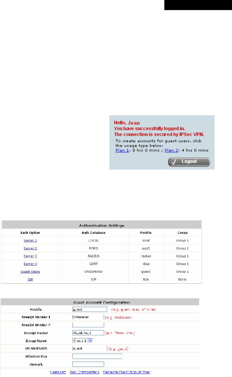
© 2008 4IPNET, INC.
49
4ipnet
MSG
100
User
’
s
Manual
Ø Transparent Login: This function refers to Windows NT Domain single sign on. When
Transparent Login is enabled, clients will log in to the system automatically after they have
logged in to the NT domain, which means that clients only need to log in once.
4.2.1.6 ONDEMAND Authentication Database
The system provides an ONDEMAND Authentication Database of Instant Accounts for temporary
users such as visitors. For example, when visitors need to use Internet service, they can be
granted a temporary Internet access account.
>> To generate Instant Accounts
(1) As the example figure on the right, authorized
users can generate Instant Accounts by clicking
links on their Login Success Page on their
computers. (2) The administrator can also click the
hyperlink of the Generate Guest Account User
link on the Guest Account Generation page to
generate Instant Accounts.
A newly generated account will be displayed on a pop-up window and can be printed through a
network printer if available. The pop-up window will show two lines of header and one line of footer
along with a Username/Password pair and other information required.
Click Guest Users to enter the Guest Account Configuration page.
Ÿ Postfix: Set a postfix that is easy to distinguish (e.g. Guest) by using numbers (0~9),
alphabets (a~z or A~Z), dash (-), underline (_) and dot (.) within a maximum of 40 characters.
All other characters are not allowed.
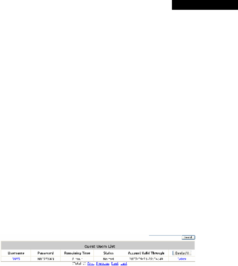
© 2008 4IPNET, INC.
50
4ipnet
MSG
100
User
’
s
Manual
A postfix is used to inform the system which authentication option is used for authenticating an
account (e.g. bob@BostonLdap or tim@TokyoRadius) when multiple options are concurrently
in use. One of authentication options can be assigned as default. The postfix can be omitted
only when the default authentication option is used. For example, if "BostonLdap" is the postfix
of the default option, Bob can log in with either "bob" or "bob@BostonLdap” as his username.
Ÿ Receipt Header: There are two receipt headers supported by the system. The entered content
will be printed on the receipt. These headers are optional.
Ÿ Receipt Footer: The entered content will be printed on the receipt. This footer is optional.
Ÿ Group Name: All guest users can be applied with the same Group option. Select the desired
Group from the drop-down list box.
Ÿ WLAN ESSID: The administrator can enter the defined wireless ESSID in this field and it will
be printed on the receipt for guest users’ reference when accessing the Internet via wireless
LAN service. The ESSIDs given here should be those of the Service Zones enabled for guest
users.
Ÿ Wireless Key: The administrator can enter the defined wireless key such as WEP or WPA in
the field. The Wireless Key will be printed on the receipt for the guest users’ reference when
accessing the Internet via wireless LAN service.
Ÿ Remark: The administrator can enter extra information in this field for remark.
Ÿ Users List: Click the hyperlink of Users List to enter the Guest Users List page. By default,
the Guest Users List is empty. The related information of generated Instant Accounts, such as
password and status, will be shown in this list. In addition, the administrator can delete a
specific guest user or all guest users in this list.
Ø Search: Enter a keyword of a username to be searched in the text filed and click this
button to perform the search. All usernames matching the keyword will be listed.
Ø Username: The login name of guest users.
Ø Password: The login password of guest users.
Ø Remaining Time: The total time that guest users can use currently.
Ø Status: The status of guest user accounts.
o Normal indicates that the account is not in-use and not overdue.
o Online indicates that the account is in-use and not overdue.
o Expire indicates that the account is overdue and cannot be used.
Ø Account Valid Through: The expiration time of the account.
Ø Delete All: This will delete all the users at once.
Ø Delete: This will delete the users individually.
Ÿ Plan Configuration: The system supports two plans for guest users. Click the hyperlink of
Plan Configuration to enter the Guest Account Plan Configuration interface, where the
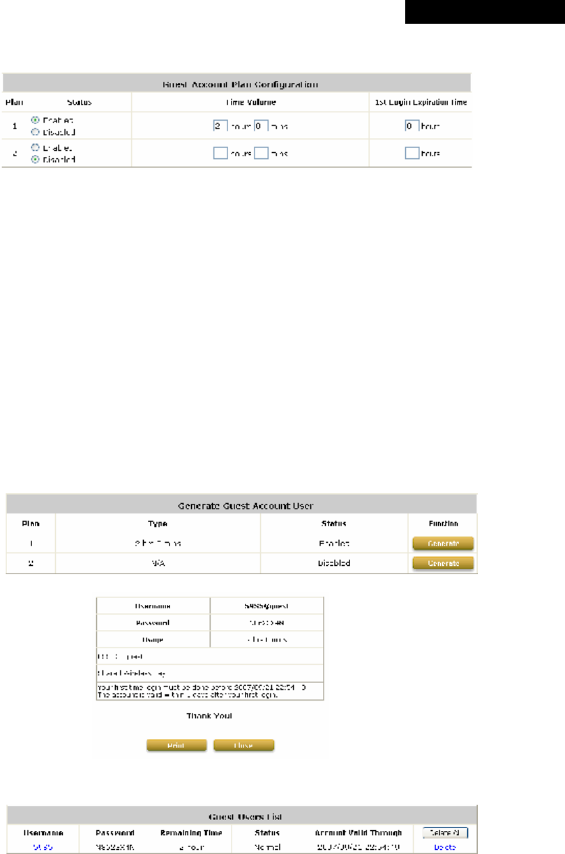
© 2008 4IPNET, INC.
51
4ipnet
MSG
100
User
’
s
Manual
administrator can configure up to 2 usage plans.
Ø Plan: The ID of a plan.
Ø Status: Enable or Disable the plan.
Ø Time Volume: The Time Volume is how long guest users are allowed to access the
Internet.
Ø 1st Login Expiration Time: It is a given time period that a guest account must be
activated after it is generated. The account will become expired if the guest user does
not login within the given time.
• Generate Guest Account User: When at least one plan is enabled, the administrator can
generate Instant Accounts here. Click the hyperlink of Generate Guest Account User to enter
the Generate Guest Account User page. Click Generate of the desired plan and then an
instant guest account will be created. Click Print to print a receipt containing the guest user
account’s information, including the username and password. (The printer used for Print must
be pre-configured to connect to the administrator PC.)
A guess user account is now generated as follows in the Guest Users List:
4.2.1.7 SIP Authentication
The system supports SIP transparent proxy for SIP clients (e.g. soft phones) to pass through NAT.
When the SIP Authentication option is enabled, all SIP traffic can pass through NAT via a fixed
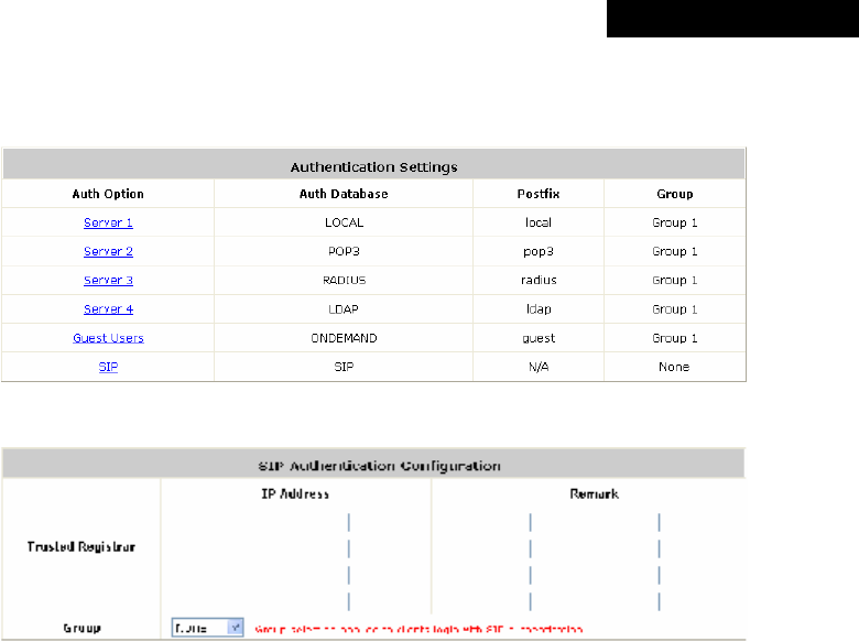
© 2008 4IPNET, INC.
52
4ipnet
MSG
100
User
’
s
Manual
WAN interface. Up to four trusted SIP Registrars can be set in the SIP Authentication
Configuration page. All SIP clients can be selected as a Group.
Click SIP to enter the SIP Authentication Configuration page.
Ÿ Trusted Registrar: The SIP Authentication supports up to 4 trusted SIP registrars. When SIP
clients try to use the network service, they must be authenticated by one of the configured SIP
registrars. SIP traffic can pass through NAT after a successful authentication.
Ÿ IP Address: The IP address of the Trusted SIP Registrar.
Ÿ Remark: The administrator can enter extra information in this field for remark.
Ÿ Group: A Group option can be applied to the clients who login with SIP Authentication. Be noted
that the specific route of the applied Policy for the selected Group cannot conflict with the
assigned WAN interface for SIP authentication.
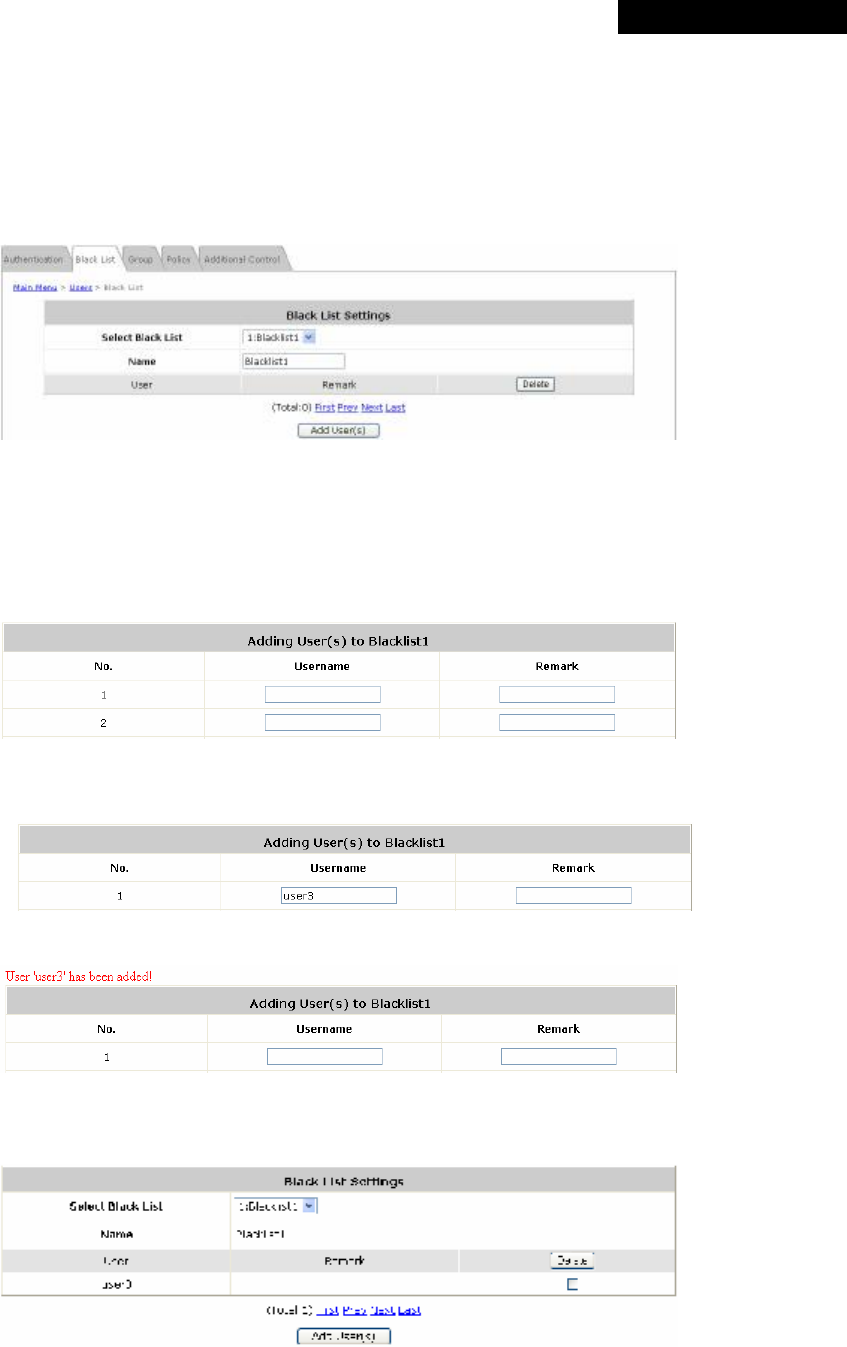
© 2008 4IPNET, INC.
53
4ipnet
MSG
100
User
’
s
Manual
4.2.2 Black List
The administrator can add or delete users in the black list for user access control. There are 5 sets of black lists
provided by the system. A user account listed in the black list is not allowed to log into the system. The
administrator can select one black list from the drop-down list box to be applied to this specific authentication
option.
Ÿ Select Black List: Select one black list from the drop-down list box.
Ÿ Name: Set the name for the selected black list, which will show in the above drop-down list.
Ÿ Add User(s): After clicking Add User(s), the Add User(s) to Blacklist page will appear for adding users to the
selected black list.
Enter usernames in the Username field and the related information in the Remark field (not compulsory).
Click Apply to save the settings and the following page will appear
If the administrator wants to remove a user from the black list, just select the user’s Delete check box, and then
click Delete to remove the selected user from the black list.
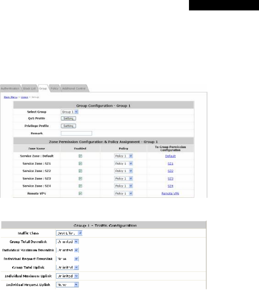
© 2008 4IPNET, INC.
54
4ipnet
MSG
100
User
’
s
Manual
4.2.3 Group
8 sets of Group options including QoS Profile, Privilege Profile with Instant Account Privilege and Change
Password Privilege, and Zone Permission Configuration & Policy Assignment can be defined respectively to
enforce access controls on different Groups of users. Local users can be classified by applying Group options. A
Group which is allowed to access a Service Zone can be applied with a Policy within this zone. The same Group
within different Service Zones can be applied with different Policies as well as different Authentication Options.
Ÿ Group Configuration – Group 1
Ø QoS Profile: Set parameters for traffic classification.
o Traffic Class: A Traffic Class can be chosen for a Group of users. There are four traffic classes:
Voice, Video, Best-Effort and Background. Voice and Video traffic will be placed in the high priority
queue. When Best-Effort or Background is selected, more bandwidth management options such as
Downlink and Uplink Bandwidth will appear.
o Group Total Downlink: Defines the maximum bandwidth allowed to be shared by clients within this
Group.
o Individual Maximum Downlink: Defines the maximum downlink bandwidth allowed for an individual
client belonging to this Group. The Individual Maximum Downlink cannot exceed the value of Group
Total Downlink.
o Individual Request Downlink: Defines the guaranteed minimum downlink bandwidth allowed for an
individual client belonging to this Group. The Individual Request Downlink cannot exceed the value
of Group Total Downlink and Individual Maximum Downlink.
o Group Total Uplink: Defines the maximum uplink bandwidth allowed to be shared by clients within
this Group.
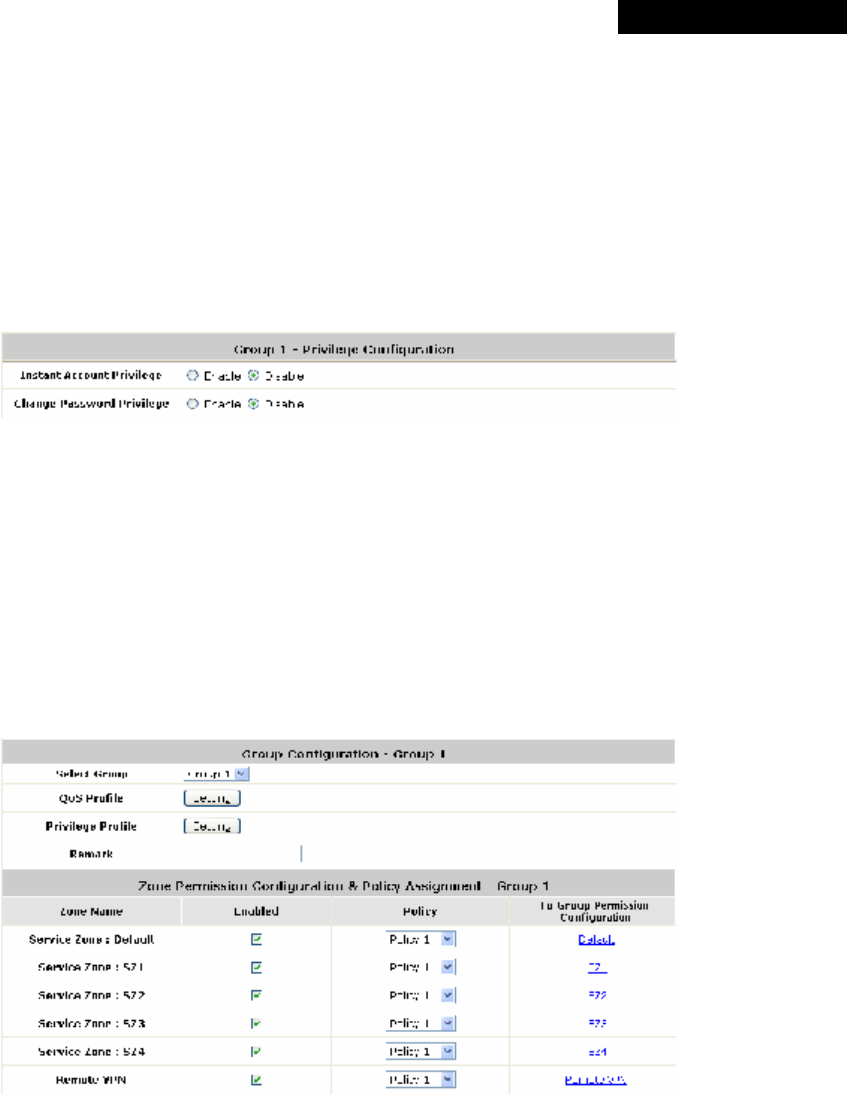
© 2008 4IPNET, INC.
55
4ipnet
MSG
100
User
’
s
Manual
o Individual Maximum Uplink: Defines the maximum uplink bandwidth allowed for an individual client
belonging to this Group. The Individual Maximum Uplink cannot exceed the value of Group Total
Uplink.
o Individual Request Uplink: Defines the guaranteed minimum bandwidth allowed for an individual
client belonging to this Group. The Individual Request Uplink cannot exceed the value of Group Total
Uplink and Individual Maximum Uplink.
Ø Privilege Profile: Includes Maximum Concurrent Session for User, PPTP login, Instant Account
Privilege and Change Password Privilege.
o Instant Account Privilege: When Instant Account Privilege is enabled, the authenticated local users
within this Group are allowed to create instant accounts via the Login Success Page.
o Change Password Privilege: When Change Password Privilege is enabled, the authenticated local
users within this Group are allowed to change their password via the Login Success Page.
Ÿ Zone Permission Configuration & Policy Assignment – Group X
A Group can be assigned to one Service Zone or multiple Service Zones. Moreover, a Group can be applied
with different Policies within different Service Zones. Remote VPN is considered as a zone, where clients log
into the system via remote VPN.
Ø Zone Name: The name of Service Zones and Remote VPN.
Ø Enabled: Select Enabled to allow clients of this Group to log into the selected Service Zones. For
example, the above figure shows that users in Group 1 can access network services via every Service
Zone as well as Remote VPN under constraints of Policy 1.
Ø Policy: Select a Policy that the Group will be applied with when accessing respective Service Zones.
Ø To Group Permission Configuration: The relation between Group and Service Zone is many to many;
every Group can access network services via more than one Service Zone, and meanwhile, each
Service Zone can serve more than one Group.
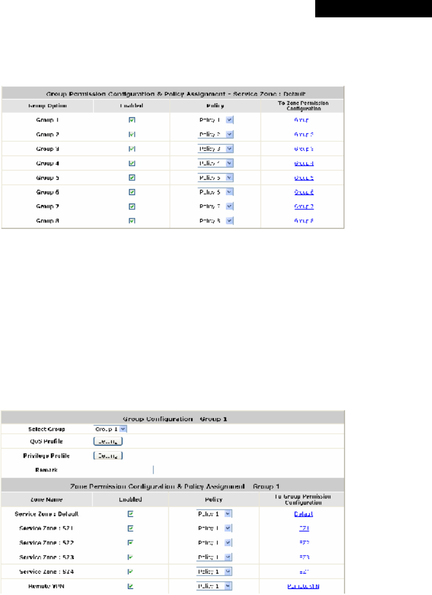
© 2008 4IPNET, INC.
56
4ipnet
MSG
100
User
’
s
Manual
Click the hyperlink in the To Group Permission Configuration column to enter the Group Permission
Configuration & Policy Assignment interface, which is based on the role of Service Zone, to configure the
relation between Group and Zone.
o Group Option: The name of Group options available for selection.
o Enabled: Select Enabled to allow clients of the enabled Groups to log in to this Service Zone under
constraints of the selected Policies.
Check Enabled of each individual Group to assign it to the Service Zone listed. For example, the
above figure shows that clients in Group 1~8 can access Default Service Zone, where they are
governed by Policy 1~8 respectively.
o Policy: Select a Policy that the Group will be applied with when accessing this Service Zone.
o To Zone Permission Configuration: Click the hyperlink in the To Zone Permission Configuration
column to enter Zone Permission Configuration & Policy Assignment interface, which is based
on the role of Group, to configure the relation between Group and Zone.
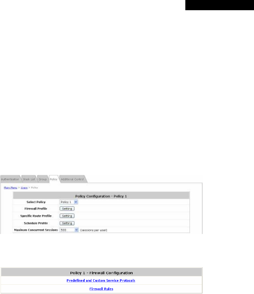
© 2008 4IPNET, INC.
57
4ipnet
MSG
100
User
’
s
Manual
4.2.4 Policy
MSG100 supports multiple Policies, including one Global Policy and 12 individual Policy. Each Policy consists of
access control profiles that can be configured respectively and applied to a certain Group of users. Global Policy
is the system’s universal policy and applied to all clients, while other individual Policy can be selected and defined
to be applied to any Service Zone.
The clients belonging to a Service Zone will be bound by an applied Policy. In addition, a Policy can be applied at a
Group basis; a Group of users can be bound by a Policy. The same Group can be applied with different Policies
within different Service Zones.
When the type of authentication database is RADIUS, the Class-Group Mapping function will be available to allow
the administrator to assign a Group for a RADIUS class attribute; therefore, a Policy applied to this Group will be
mapped to a user Group of a RADIUS class attribute. When the type of authentication database is LDAP, the
Attribute-Group Mapping function will be available to allow the administrator to assign a Group for a LDAP
attribute; therefore, a Policy applied to this Group will be mapped to a user Group of a LDAP attribute. When the
type of database is SIP, the Group selection function will be available to allow the administrator to assign a Group
option for all SIP clients.
• Select Policy: Select a Policy for further configuration. Below depicts an example of selecting Policy 1.
• Firewall Profile: Each Policy has a firewall service list and a set of firewall profile consisting of firewall rules.
Ø Predefined and Custom Service Protocols: This link leads to a Service Protocols List where the
administrator can define a list of service by protocols (TCP/UDP/ICMP/IP). There are predefined service
protocols available for firewall rules editing. The administrator is able to add new customized service
protocols by clicking Add, and delete the added protocols by clicking Delete.
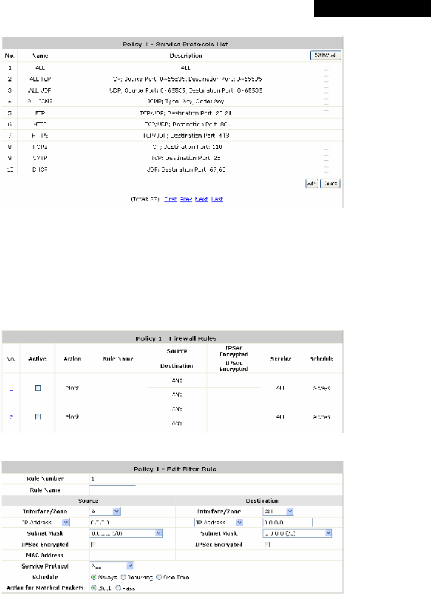
© 2008 4IPNET, INC.
58
4ipnet
MSG
100
User
’
s
Manual
Ø Firewall Rules: Click on the hyperlink in the No. column to edit individual rules and then click Apply to
save the settings. The rule status will show on the list. Check the Active check box and click Apply to
enable that rule. This link leads to the Firewall Rules page. Rule No.1 has the highest priority; Rule No.2
has the second priority and so on. Each firewall rule is defined by Source, Destination and Pass/Block
action. Optionally, a Firewall Rule Schedule can be set to specify when the firewall rule is enforced. It can
be set to Always, Recurring or One Time.
Below depicts an example of selecting Filter Rule Number 1:
o Rule Number: This rule number of the selected rule. Rule No. 1 has the highest priority; Rule No.
2 has the second priority, and so on.
o Rule Name: The rule name can be changed here.
o Source / Destination – Interface/Zone: There are choices of ALL, WAN1, WAN2, Default and the
Service Zones to be applied to the traffic interface.
o Source / Destination – IP Address/Domain Name: Enter the source and destination IP
addresses.
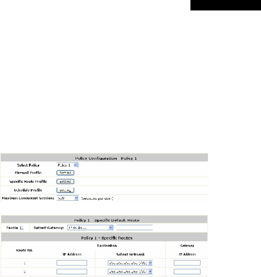
© 2008 4IPNET, INC.
59
4ipnet
MSG
100
User
’
s
Manual
o Source / Destination – Subnet Mask: Enter the source and destination subnet masks.
o Source / MAC Address: The MAC Address of the source IP address. This is for specific MAC
address filter.
o Source / Destination – IPSec Encrypted: Check the box to filter the encrypted traffic only.
o Service Protocol: Select a defined protocol from the drop-down list box.
o Schedule: Defines the time when this firewall rule will be activated. When a schedule is selected,
the clients assigned to this Policy are applied with the firewall rule only within the time selected.
There are three options, Always, Recurring and One Time.
o Action for Matched Packets: There are two options, Block and Pass. Block is to prevent packets
from passing, while Pass is to permit packets passing.
• Specific Route Profile: The default gateway of WAN1, WAN2, or a desired IP address can be defined in a
Policy. When Specific Default Route is enabled, all clients applied with this Policy will access the Internet
through this default gateway.
Click Setting of Specific Route Profile to enter the Specific Route page for further configuration.
Ø Enable: Check the Enable box to activate this function or uncheck to inactivate it.
Ø Destination / IP Address: The destination network address or IP address of the destination host.
Please note that, if applicable, the system will calculate and display the appropriate value based on the
combination of Network/IP Address and Subnet Mask that are just entered and applied.
Ø Destination / Subnet Netmask: The subnet mask of the destination network. Select
255.255.255.255(/32) if the destination is a single host.
Ø Gateway / IP Address: The IP address of the gateway or next router to the destination.
• Schedule Profile: Click Setting of Schedule Profile to enter the configuration page. Select Enable to show the
Permitted Login Hours list. This function is used to limit the time when clients can log in. Check the desired
time slots and click Apply to save the settings. These settings will become effective immediately after clicking
Apply.
• Maximum Concurrent Session: Set the maximum concurrent sessions for each client.
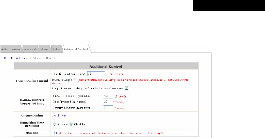
© 2008 4IPNET, INC.
60
4ipnet
MSG
100
User
’
s
Manual
4.2.5 Additional Control
In this section, additional settings are provided for user management.
Ÿ User Session Control: Functions under this section applies to all general users.
Ø Idle Timeout: Defines the time when the system will log out a user when he has been inactive for a time
period set in this field. This setting will be applied to all users.
Ø Multiple Login: When Multiple Login is enabled, different clients can log in with the same account at the
same time. This function is not valid for Instant Account and RADIUS Account.
Ø Logout upon closing the “Login Success” window: When this feature is enabled, there will be a new
popup window for the users to confirm if they want to log out the system when they try to close the Login
Success Page in case it is closed by accident.
Ÿ Built-in RADIUS Server Settings
Ø Session Timeout: Defines the time limit for Internet access for users who are authenticated by the built-in
RADIUS server. The system will log out such users when Session Timeout is reached.
Ø Idle Timeout: Defines the time when the system will log out a user when he has been inactive for a time
period set in this field. This setting will be applied to users who are authenticated by the built-in RADIUS
server.
Ø Interim Update: Defines the time when the system will update records of users who are authenticated by
the built-in RADIUS server constantly.
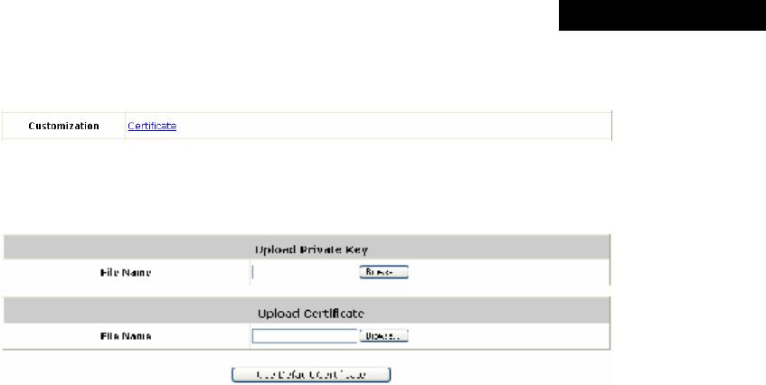
© 2008 4IPNET, INC.
61
4ipnet
MSG
100
User
’
s
Manual
Ÿ Customization: The administrator can upload a new private key and an external certificate issued by public or
private authority. Click Certificate button to enter the configuration interface.
Click the first Browse button to locate the file of the Private Key. Click the second Browse button to locate the
file of the Certificate to be uploaded. Next, click Apply to complete the upload process.
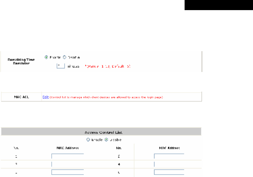
© 2008 4IPNET, INC.
62
4ipnet
MSG
100
User
’
s
Manual
Ÿ Remaining Time Reminder: There is a Remaining Time Reminder supported by the system to remind guest
users that their accounts are about to expire within the given time. When this function is enabled, there will be a
reminding message appearing on guest users’ screen at a given time before expiration.
Ÿ MAC ACL: Click Edit to enter Access Control List for further configuration.
Enter the MAC Address of network devices. When MAC ACL is enabled, only the clients with their MAC
addresses listed in this list can log into the system.
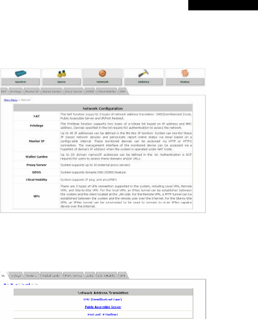
© 2008 4IPNET, INC.
63
4ipnet
MSG
100
User
’
s
Manual
4.3 Network
This section provides information on NAT, Privilege, Monitor IP, Walled Garden, Proxy Server, DDNS, Client
Mobility and VPN.
4.3.1 NAT
There are three options of Network Address Translation that can be configured: DMZ, Virtual Servers and Port
and IP Redirect.
Ÿ DMZ (Demilitarized Zone)
The administrator can use DMZ to define mandatory external to internal IP mapping, so that clients on the
WAN can access a private machine (e.g. a PC, a system) on the LAN via a specified external IP. For
Automatic WAN IP Assignment, check the Enable check box to enable Automatic WAN IP Assignment and
enter an Internal IP address. For Static Assignments, enter Internal and External IP Addresses as a set and
choose to use WAN1 or WAN2 as the External Interface. These settings will become effective immediately
after clicking Apply.
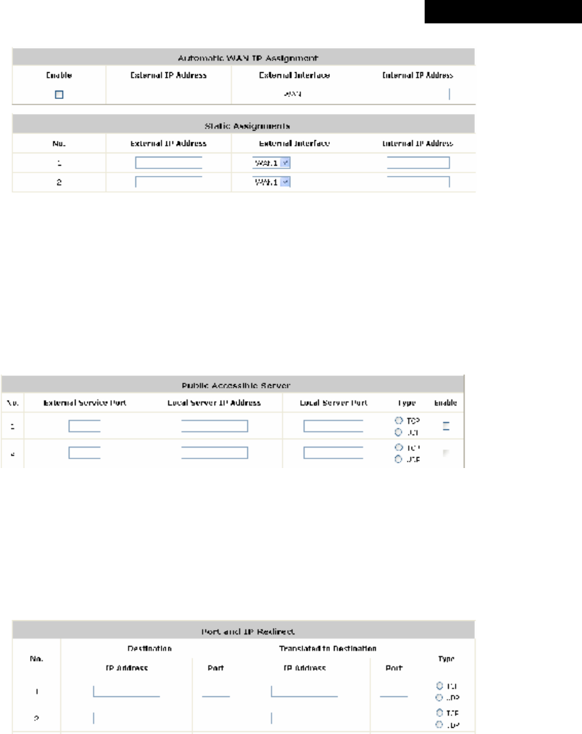
© 2008 4IPNET, INC.
64
4ipnet
MSG
100
User
’
s
Manual
Ÿ Public Accessible Server
The administrator can set virtual servers by using this function, so that the computers outside the managed
network can access the servers within the managed network via WAN ports of MSG100. Enter the External
Service Port, Local Server IP Address and Local Server Port accordingly. Different virtual servers can be
configured for different sets of physical services, such as TCP and UDP services in general. Select TCP or
UDP protocol for the service’s type. In the Enable column, check the desired server to be enabled. These
settings will be effective immediately after clicking Apply.
Ÿ Port and IP Redirect
In this function, the administrator can set up to 40 sets of the IP address ports for redirection purpose. When
users attempt to connect to the port of a Destination IP Address listed here, the connection packet will be
converted and redirected to the port of the Translated to Destination IP Address. Enter the IP Address and
Port of Destination, and the IP Address and Port of Translated to Destination. Select TCP or UDP protocol
for the service’s type. These settings will become effective immediately after clicking Apply.
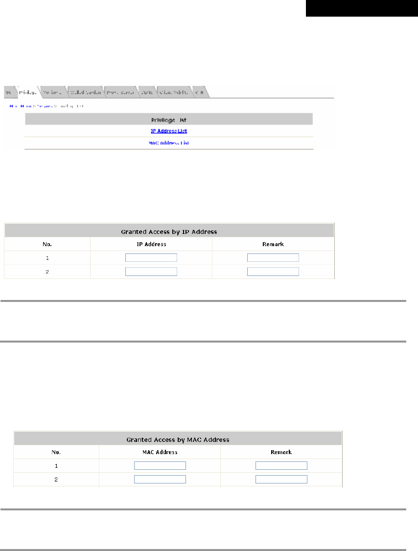
© 2008 4IPNET, INC.
65
4ipnet
MSG
100
User
’
s
Manual
4.3.2 Privilege List
MSG100 provides two privilege lists: IP Address List and MAC Address List. The IP addresses and MAC
addresses stated in these lists are allowed to access the network without authentication.
Ÿ IP Address List
The clients (such as workstations) in the Granted Access by IP Address list are allowed to access the Internet
directly without authentication. Enter the IP Address of the clients. The Remark is optional but useful for
tracking purpose. These settings will become effective immediately after clicking Apply.
8 Note:
Permitting specific IP addresses to have network access rights without going through standard
authentication process at the authentication-required Service Zones may cause security
problems.
Ÿ MAC Address List
The clients in the Granted Access by MAC Address list are allowed to access the Internet directly without
authentication. Enter the MAC Address of the clients (in format: xx:xx:xx:xx:xx:xx). The Remark is optional but
useful for tracking purpose. These settings will be effective immediately after clicking Apply.
8 Note:
Permitting specific MAC addresses to have network access rights without going through standard
authentication process at the authentication-required Service Zones may cause security
problems.
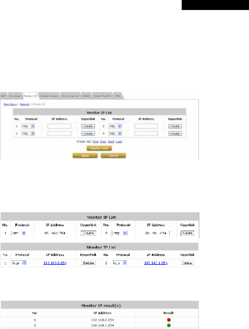
© 2008 4IPNET, INC.
66
4ipnet
MSG
100
User
’
s
Manual
4.3.3 Monitor IP
The system can monitor the devices listed in the Monitor IP List by pinging them periodically. The administrator
can use this function to monitor third-party APs or any other IP-based devices, and moreover, hyperlinks of
destination IP addresses can be created to access the monitoring devices. A notification e-mail of monitored status
can be set to notify the administrator in a configured time period.
Click Apply to activate the settings immediately.
For more information, please refer to Section 4.5.6. E-mail & SYSLOG.
Ÿ Protocol: Select either http or https according to the IP type to be monitored; https for encrypted IP and http for
unencrypted IP.
Ÿ IP Address: Enter the IP Address of devices to be monitored.
Ÿ Hyperlink: Click Create to generate a hyperlink of the IP Address entered. Click Delete to inactivate the
hyperlink.
Ÿ Monitor Now: Click this button to execute the monitor action manually, and the Monitor IP Result(s) page with
status of monitored devices will appear. If the entered IP address is unreachable, a red dot in the Result
column will appear. A green dot indicates that the IP address is reachable and alive.
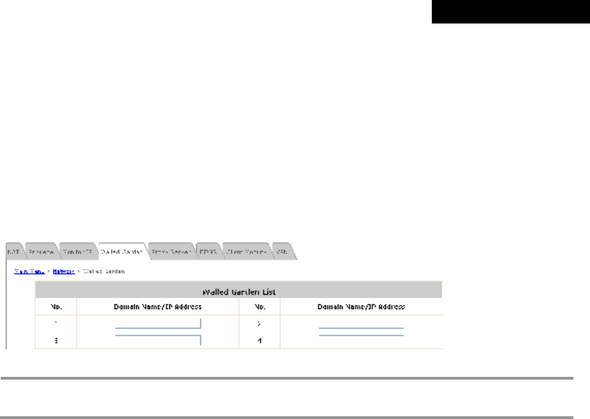
© 2008 4IPNET, INC.
67
4ipnet
MSG
100
User
’
s
Manual
4.3.4 Walled Garden
The Walled Garden supported by the system provides free surfing areas for clients to access before they are
authenticated by the system. IP addresses or domain names of the websites can be defined in this list. Clients
without network access right can still have a chance to experience actual network services free of charge. This
function allows clients to access specified websites before login and authentication. For example, in a hotel, a
guest without network access right can be allowed to access the hotel’s homepage free of charge. Up to 20
addresses or domain names of websites can be defined in this list. The settings will be effective immediately after
clicking Apply.
8 Note:
To use the domain name, the system must connect to a DNS server first, or this function will not
work.
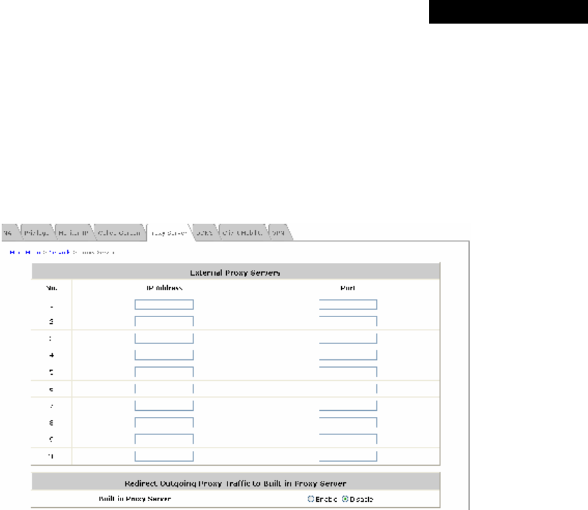
© 2008 4IPNET, INC.
68
4ipnet
MSG
100
User
’
s
Manual
4.3.5 Proxy Server
This feature can be used for clients whose computers are with proxy server enabled configuration. The system
supports external proxy servers and will match the proxy settings of External Proxy Servers listed here to that of
clients in their browsers when they are trying to access the Internet. If there is no match, clients will not be able to
get User Login Page, and therefore, be unable to access the Internet. If there is a match, clients will be directed to
User Login Page for authentication. After a successful authentication, clients will be redirected back to the desired
proxy servers.
Ÿ External Proxy Servers: The system will match the proxy setting of External Proxy Servers listed here to
that of clients to see if there is a match found in their browsers. If there is no match, clients will not be able to
get User Login Page, and therefore, be unable to access the Internet. If there is a match, clients will be directed
to User Login Page for authentication.
Ÿ Redirect Outgoing Proxy Traffic To Built-in Proxy Server: The system has a built-in proxy server. If this
function is enabled, clients will be forced to use the built-in proxy server regardless of clients’ original proxy
settings after being successfully authenticated, and then all traffic will be redirected through the built-in proxy
server.
For more information on setting up the proxy servers, please refer to Appendix E – Proxy Setting.
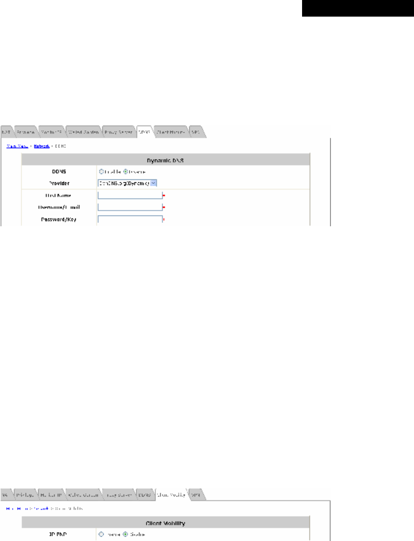
© 2008 4IPNET, INC.
69
4ipnet
MSG
100
User
’
s
Manual
4.3.6 DDNS
The system provides a convenient dynamic DNS (DDNS) function to translate the IP address of WAN port to a
domain name that helps the administrator memorize and connect to WAN1 port. When the DDNS is enabled, the
system will send the latest IP address regularly to the specified DNS server if the WAN1 interface is set to Dynamic.
These settings will become effective immediately after clicking Apply.
Ÿ DDNS: Enable or disable this function.
Ÿ Provider: Select a DNS provider.
Ÿ Host name: The IP address/domain name of the WAN port.
Ÿ Username/E-mail: The registered ID (username or e-mail) with the DNS provider.
Ÿ Password/Key: The registered password with the DNS provider.
For more information on setting up the proxy servers, please refer to Appendix E – Proxy Setting.
4.3.7 Client Mobility
The system supports IP PNP function. When enabled, this function allows clients with fixed or assigned IP
addresses to be authenticated by the system to access the network. By enabling IP PNP, a PC with a completed
static IP address configuration will be able to access the network even if the built-in DHCP server of the system is
enabled. No TCP/IP reconfiguration is needed.
Ÿ IP PNP: When IP PNP is enabled, a PC with a static IP address can still access the network even if the built-in
DHCP server of the system is enabled. No TCP/IP reconfiguration is needed.
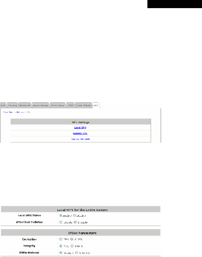
© 2008 4IPNET, INC.
70
4ipnet
MSG
100
User
’
s
Manual
4.3.8 VPN
Virtual Private Network (VPN) is designed to increase the security of information transmitted over the Internet. VPN
can work with wired or wireless networks and create a private encrypted independent tunnel from a client device to
the system, or through the Internet to corporate servers and databases. There are 3 types of VPN connection
supported by the system: Local, Remote, and Site-to-Site.
Windows Vista clients are supported to use Local VPN, which is implemented by PPTP for the limitation of
Microsoft. Therefore, a VPN tunnel of Windows Vista behaves differently from that of Windows XP or 2000, and
moreover, Windows Vista’s Local VPN uses the configuration of Remote VPN. When Remote VPN is disabled,
Windows Vista clients can only login via non-VPN even though they are configured as Local VPN required.
Ÿ Local VPN:
When Local VPN is enabled, the system will create a VPN tunnel between a client and the system to encrypt
the data transmission. Local VPN is supported by client devices with Windows 2000, Windows XP SP1, SP2 or
Windows Vista enabled. Some IPSec parameters are configurable. To use this function, check Enable and
choose the desired parameters. Click Apply to activate Local VPN.
For more information on IPSec VPN, please refer to Appendix F – IPSec VPN.
Ÿ Remote VPN:
By enabling this function, the system creates a VPN tunnel via PPTP between a remote client and the system
to encrypt the data transmission. Remote VPN is supported by client devices with Windows 2000, Windows XP
SP1, SP2 or Windows Vista enabled.
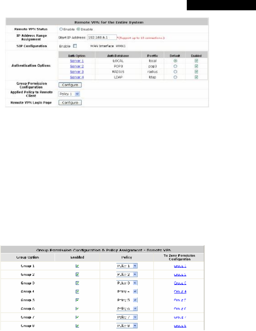
© 2008 4IPNET, INC.
71
4ipnet
MSG
100
User
’
s
Manual
Ø Remote VPN Status: Check Enable to activate Remote VPN and allow client devices with Windows Vista
enabled to use Local VPN, or Disable to inactivate it.
Ø IP Address Range Assignment: Enter the start IP address to be used, and the system will automatically
assign up to 10 IP address for clients as the system supports up to 10 remote VPN connections.
Ø SIP Configuration: The system supports SIP transparent proxy for SIP traffic from authenticated Remote
VPN clients with Windows Vista enabled to pass through NAT via a fixed WAN interface. When this
function is enabled, remote clients can access SIP services.
Ø Authentication Option: Check the Enable check box to activate the VPN function for the respective Auth
Options. Check the Default radio button to select a default authentication option. For more information on
Auth Option setting, please refer to Section 4.2.1. Authentication.
Ø Applied Policy to Remote Client: Select a Policy, where the remote VPN function will be applied with.
Ø Group Permission Configuration: Click Configure to enter the Group Permission-Remote VPN
interface for further configuration.
o Group Option: The name of the respective Group Options.
o Enabled: Check the Enable check box to activate the respective Group Options; the above figure
shows that Group 1 to 8 are all allowed to use the Remote VPN service.
o Policy: Select a desired Policy from the drop-down list box; the above figure shows that Policy 1-8
are assigned to Group 1-8 respectively for accessing the remote VPN service.
o To Zone Permission Configuration: Click on the hyperlink of Group options in the To Zone
Permission Configuration column for further configuration. Please refer to Section 4.2.3. Group
for more information.
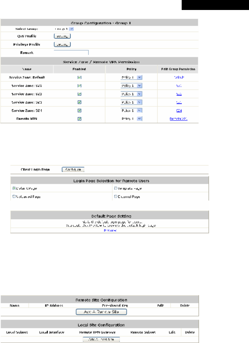
© 2008 4IPNET, INC.
72
4ipnet
MSG
100
User
’
s
Manual
Ø Client Login Page: The administrator can use the default remote VPN login page or customize the page
by setting the template page, uploading the page or downloading from a specific website. Click Preview to
view the page configured. For more information on customizing this page, please refer to “Custom Pages”
in Section 4.1.6. Service Zone.
Ÿ Site-to-Site VPN:
When Site-to-Site VPN is enabled, the system will enable an IPSec VPN tunnel between two remote
networks/sites to encrypt the data transmission. Click Add a Remote Site to set the configuration for remote
VPN capable devices, such as a VPN gateway. Click Add a Local Site to set the configuration for a local site.
An IPSec tunnel can be established and used to connect to other IPSec capable devices on the Internet.
Ø Remote Site Configuration: Click Add a Remote Site to enter the Remote VPN Gateway page for
further configuration.
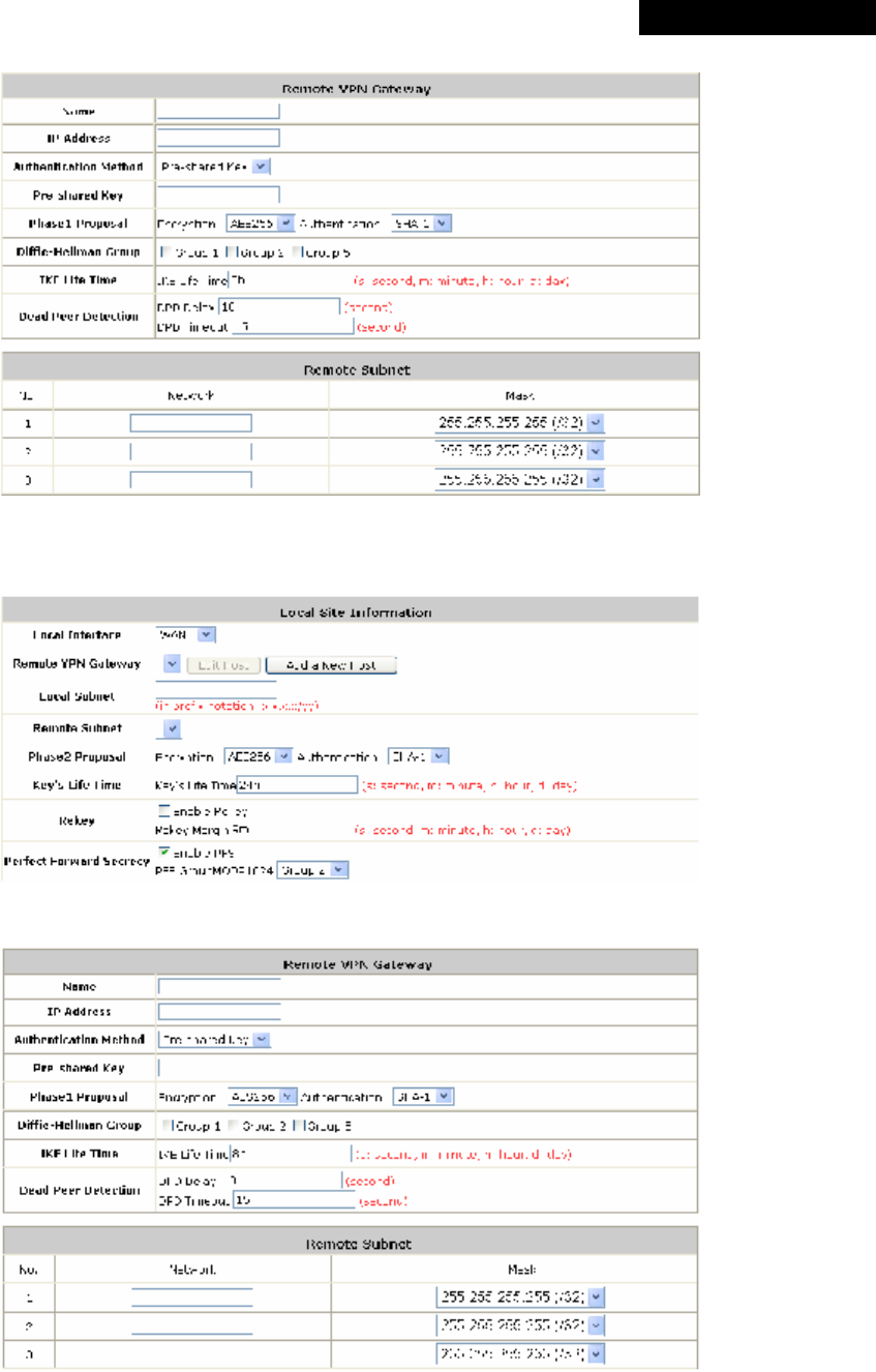
© 2008 4IPNET, INC.
73
4ipnet
MSG
100
User
’
s
Manual
Ø Local Site Configuration: Click Add a Local Site to enter the Local Site Information page for further
configuration.
Click Add a New Host to enter the Remote VPN Gateway page for further configuration.
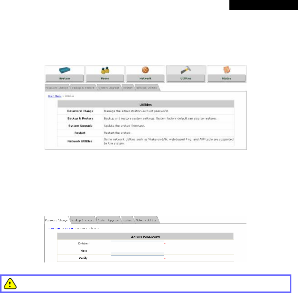
© 2008 4IPNET, INC.
74
4ipnet
MSG
100
User
’
s
Manual
4.4 Utilities
This section provides four utilities to maintain the system, including Password Change, Backup & Restore,
System Upgrade, Restart, and Network Utilities.
4.4.1 Password Change
The administrator can change the password of the system. The default admin password of the system is "admin".
Enter the original password and a new password, and then re-type the new password in the Verify field. Click
Apply to activate the new password.
If the admin password is lost or forgotten, it can still be changed in the text-mode management interface
via the serial port.
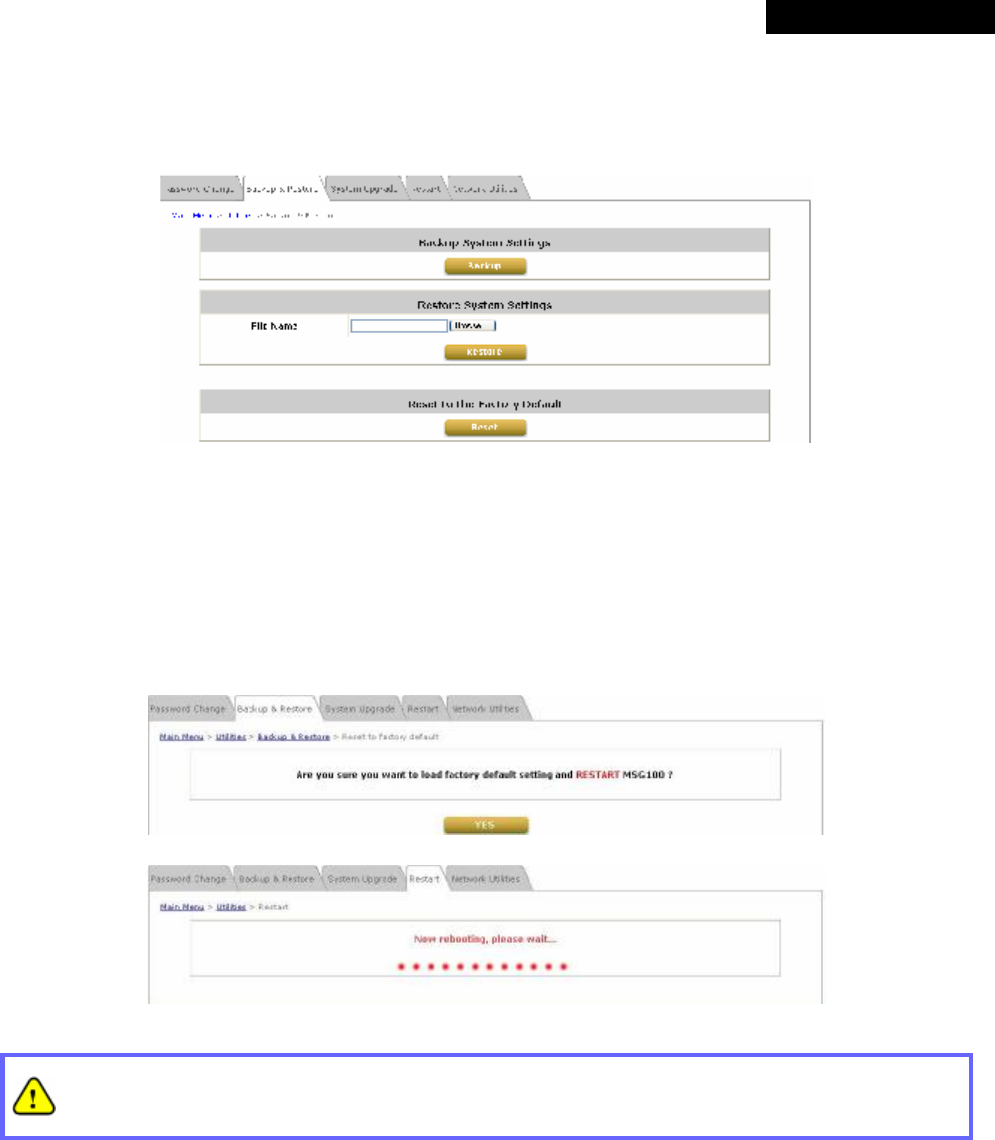
© 2008 4IPNET, INC.
75
4ipnet
MSG
100
User
’
s
Manual
4.4.2 Backup & Restore
This function is used to backup/restore the settings of MSG100. Also, MSG100 can be reset to the factory default
settings here.
Ÿ Backup System Settings: Click Backup to save the current system settings to a backup file on a local disk
through the management console. A backup file will contain the current system settings as well as the local
user accounts information.
Ÿ Restore System Settings: Click Browse to locate a .db database backup file created by MSG100 and click
Restore to restore the system to the same settings at the time when the backup file was created.
Ÿ Reset to the Factory Default: Click Reset to load the factory default settings of MSG100; the system will then
reboot the system immediately.
A Reset action will erase the existing local user accounts. To back up the local user accounts, please
export the local user accounts to a text first. Refer to “Local User List” in Section 4.2.1.1. Local
Authentication for more details.
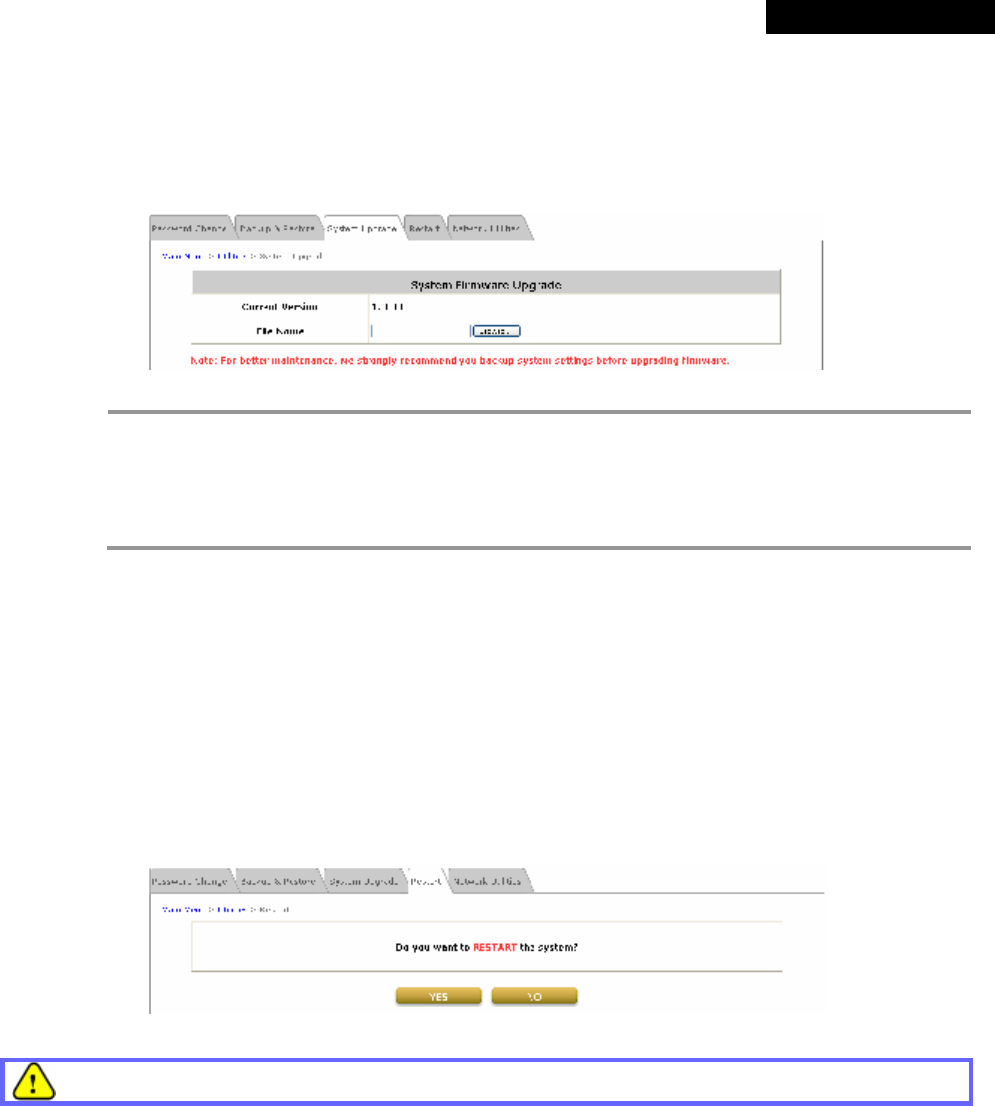
© 2008 4IPNET, INC.
76
4ipnet
MSG
100
User
’
s
Manual
4.4.3 System Upgrade
To upgrade the system firmware, click Browse to locate a new firmware file and then click Apply to execute the
upgrade process. It may take a few minutes before the upgrade process completes. Upon completion, the system
must be restarted for the new firmware to take effect.
8 Note:
Ÿ Firmware upgrade may sometimes result in data loss. Please ensure you read the release note
thoroughly before installing.
Ÿ Please restart the system after the upgrade. Do not interrupt the system, i.e. power on/off, during
the upgrade or restart process as this may damage the system.
Ÿ Current setting will not be altered after firmware upgrade.
4.4.4 Restart
This function allows the administrator to safely restart the system. The process shall take about three minutes. Do
NOT interrupt the restart process until it completes.
Click YES to restart the system. Please wait for the blinking timer to complete its countdown before accessing the
system web management interface again. Or click NO to go back to the previous screen.
All on-line users will be disconnected during reboot/restart.
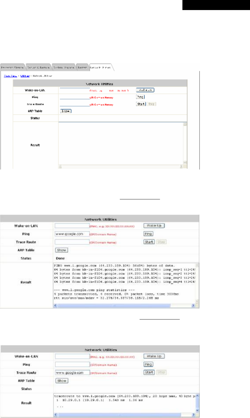
© 2008 4IPNET, INC.
77
4ipnet
MSG
100
User
’
s
Manual
4.4.5 Network Utilities
The administrator can remotely boot up a local powered off device with Wake-on-LAN enabled, via the system’s
Wake-on-LAN feature, and also be able to diagnose the network status via web-based PING, Trace Route, and
ARP Table functions.
• Wake-on-LAN: Enter the MAC address of the desired device and click Wake Up to execute this function.
• Ping: Enter the desired IP address or domain name such as “www.4ipnet.com” and click PING to execute this
function. Then, the ping result will be shown in the Result field.
• Trace Route: Enter the desired IP address or domain name such as “www.4ipnet.com” and click Start to
execute this function. Then, the progressing status will be shown in the Status field and the Trace Route result
will be shown in the Result field.
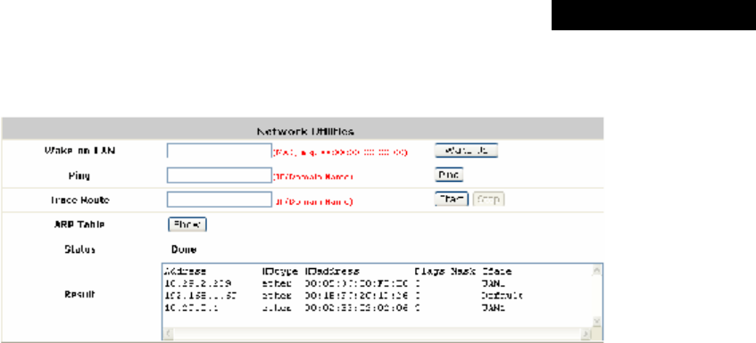
© 2008 4IPNET, INC.
78
4ipnet
MSG
100
User
’
s
Manual
• ARP Table: Click Show, and then all the IP address and MAC address of devices linked to this gateway will be
displayed in the Result field.
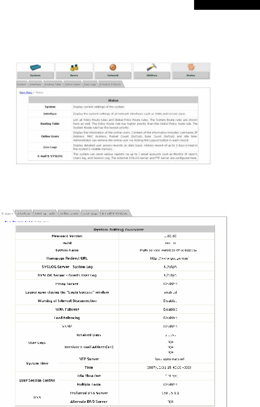
© 2008 4IPNET, INC.
79
4ipnet
MSG
100
User
’
s
Manual
4.5 Status
This section states the status on System, Interface, Routing Table, Online Users, User Logs, and E-mail &
SYSLOG.
4.5.1 System
This section provides an overview of the system status for the administrator.

© 2008 4IPNET, INC.
80
4ipnet
MSG
100
User
’
s
Manual
The description of the table is as follows:
ITEM DESCRIPTION
Firmware Version The current firmware version of MSG100.
Build The current build version of firmware.
System Name The system name. The default is MSG100.
Homepage Redirect URL The page to which the users are directed after successful login.
SYSLOG server - System Log The IP address and port number of the external SYSLOG Server. N/A
means that it is not configured.
SYSLOG server - Guests User log The IP address and port number of the external SYSLOG Server. N/A
means that it is not configured.
Proxy Server Enabled or Disabled indicates that the system is currently using the proxy
server or not.
Logout upon closing the “Login
Success” window
Enabled or Disabled indicates stands for the setting of hiding or displaying
an extra confirmation window when users try to close the login successful
window.
Warning of Internet Disconnection
Enabled or Disabled indicates that this function is active or inactive..
WAN Failover Shows the connection status of WAN1 and WAN2.
Load Balancing Shows the status of Load Balancing.
SNMP Enabled or Disabled stands for the current status of the SNMP
management function.
Retained Days
The maximum number of days for the system to retain users’ information.
User Logs Receiver E-mail
Address(es) The e-mail address that the traffic history information will be sent to.
NTP Server The network time server that the system is set to sync with.
System Time
Time The system time is shown as the local time.
Idle Time Out
The number of minutes allowed for the users to be inactive.
User Session
Control Multiple Login
Enabled or Disabled stands for the current setting of allowing or not
allowing multiple logins from the same account.
Preferred DNS
Server The IP address of the preferred DNS Server.
DNS Alternate DNS
Server The IP address of the alternate DNS Server.
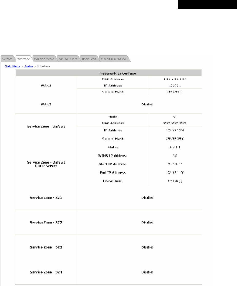
© 2008 4IPNET, INC.
81
4ipnet
MSG
100
User
’
s
Manual
4.5.2 Interface
This section provides an overview of the interface for the administrator including WAN1, WAN2, Service Zone –
Default, Service Zone – Default DHCP Server, Service Zone – SZ1/SZ2/SZ3/SZ4, and Service Zone –
SZ1/SZ2/SZ3/SZ4 DHCP Server..

© 2008 4IPNET, INC.
82
4ipnet
MSG
100
User
’
s
Manual
The description of the table is as follows:
ITEM DESCRIPTION
MAC Address The MAC address of the WAN port.
IP Address The IP address of the WAN port.
WAN1/WAN2
Subnet Mask The subnet mask of the WAN port.
Mode The mode address of the default Service Zone.
MAC Address The MAC Address of the default Service Zone.
IP Address The IP address of the default Service Zone.
Service Zone - Default/
SZ1
Subnet Mask The subnet mask of the default Service Zone.
Status Enable or Disable stands for status of the build-in DHCP server
the default Service Zone.
WINS IP
Address The IP address of the configured WINS server.
Start IP Address
The start IP address of the DHCP IP range.
End IP Address
The end IP address of the DHCP IP range.
Service Zone – Default/
SZ1 DHCP Server
Lease Time Minutes of the lease time of the IP address distributed by the
built-in DHCP server.
Service Zone – SZ2~SZ4
Disabled Enable or Disable stands for status of the Service Zone.
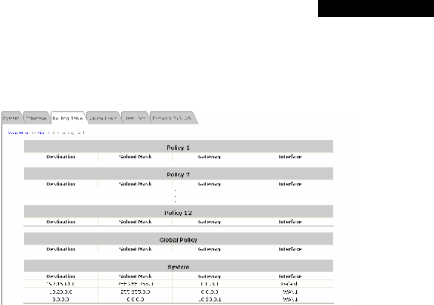
© 2008 4IPNET, INC.
83
4ipnet
MSG
100
User
’
s
Manual
4.5.3 Routing Table
The route rules of Global Policy and all individual Policies and are listed here. It also shows the route rules for
each interface of the System.
Ÿ Policy 1~12: Shows the information of each individual Policy from 1 to 12.
Ÿ Global Policy: Shows the information of the Global Policy
Ÿ System: Shows the information of the system
Ø Destination: The Destination IP address of each interface of the system.
Ø Subnet Mask: The Subnet Mask of each interface of the system.
Ø Gateway: The Gateway IP address of each interface of the system.
Ø Interface: The selected interface shown as WAN1, WAN2, Default or the name of enabled Service
Zones.
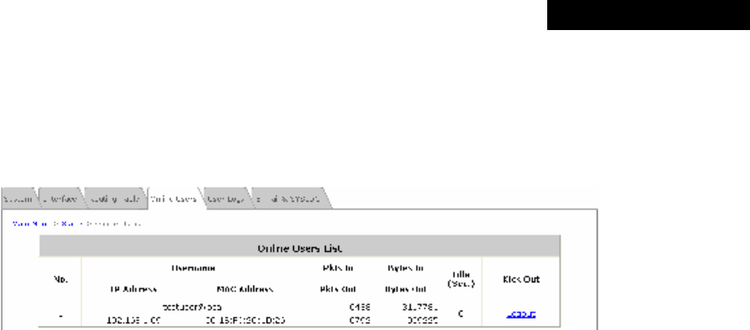
© 2008 4IPNET, INC.
84
4ipnet
MSG
100
User
’
s
Manual
4.5.4 Online Users
In this function, each online user’s information can be obtained, including Username, IP Address, MAC Address,
Pkts In, Pkts Out, Bytes In, Bytes Out, Idle, and Kick Out. The administrator can use this function to force a
specific online user to log out, or terminate any user session by clicking the hyperlink of Logout.
Click Refresh to renew the current users list.
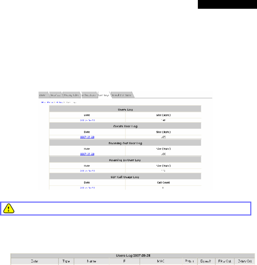
© 2008 4IPNET, INC.
85
4ipnet
MSG
100
User
’
s
Manual
4.5.5 User Logs
This function is used to check the history of the system. The history of each day will be saved separately for at least
3 days (72 full hours). Please note that these records are stored in the volatile memory and will be lost if the system
is powered off.
If the Receiver E-mail Address has been provided and Users Log has been selected under the E-mail & SYSLOG
tab, then the system will automatically send the history report to that e-mail address.
Since the history is saved in the DRAM, if you need to restart the system, and at the same time, keep the
history, please manually copy and save the history information before restarting.
Ÿ Users Log:
The Users Log provides information on each user’s login and logout activities except guest users and RADIUS
roaming in/out users.
Ø Date: The date and time that the activities took place.
Ø Type: The activity type such as Login, Logout, Create, Expired and so on.
Ø Name: The name of the user.
Ø IP: The IP address of the user.
Ø MAC: The MAC address of the user.
Ø Pkts In/Out: The amount of inbound/outbound traffic in packets.
Ø Bytes In/Out: The amount of inbound/outbound traffic in bytes.
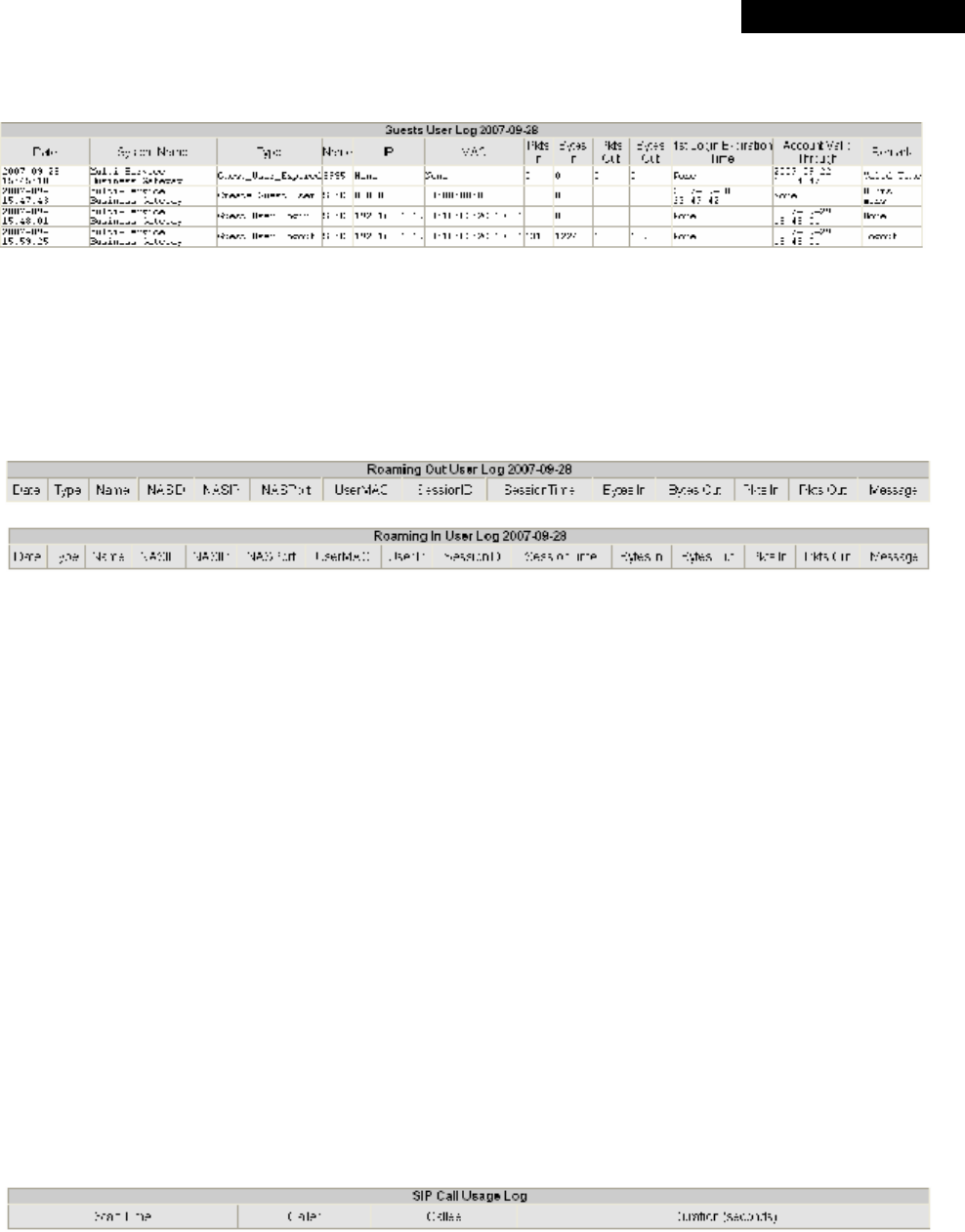
© 2008 4IPNET, INC.
86
4ipnet
MSG
100
User
’
s
Manual
Ÿ Guest Users Log:
The Guests User Log provides information on the login and logout activities of guest users.
Ø System Name: The system name.
Ø 1st Login Expiration Time: This is a given time period that the account must be activated after it is
generated and it is a constant value of one day.
Ø Account Valid Through: The expiration time of the account.
Ÿ Roaming Out/ In User Log:
The Roaming Out/ In User Log provides information on the login and logout activities of roaming out/ in users.
Ø Type: The authentication and accounting type of the RADIUS server. There are three types of
accounting: Start, Interim-update and Stop.
Ø Name: The name of the roaming user.
Ø NASID: The System ID of the system. Usually, NASID is the MAC address of the WAN port of the
system.
Ø NASIP: The IP address of the WAN port of the system.
Ø NASPort: The WAN port of the system.
Ø UserMAC: The MAC address of the user.
Ø UserIP: The IP address of the roaming user.
Ø SessionID: The system will give a unique Session ID to an authenticated user when he/she starts a new
session.
Ø SessionTime: The time of this session in seconds
Ø Bytes In/Out: The amount of inbound/outbound traffic in bytes.
Ø Pkts In/Out: The amount of inbound/outbound traffic in packets.
Ø Message: The system’s response when the client stops this session.
Ÿ SIP Call Usage Log:
The SIP Call Usage Log provides information on the login and logout activities of SIP users; all SIP call
activities will be recorded here.
Ø Start Time: The starting time, date, year of the call.
Ø Caller: The caller’s IP address.
Ø Callee: The receiver’s IP address.
Ø Duration (seconds): The time duration of this call in seconds.
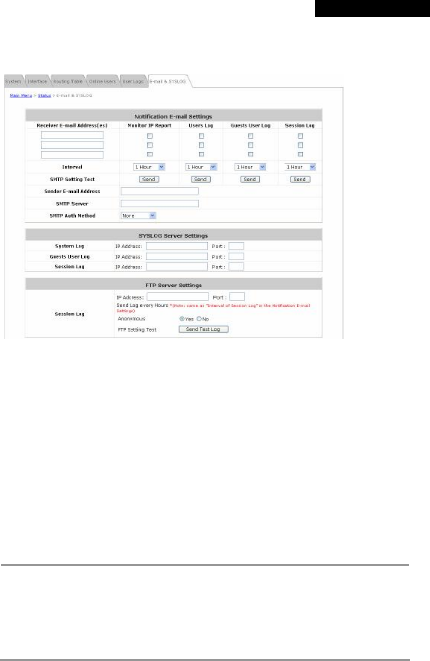
© 2008 4IPNET, INC.
87
4ipnet
MSG
100
User
’
s
Manual
4.5.6 E-mail & SYSLOG
The system supports multiple reporting options via different methods including email, SYSLOG, and FTP.
• Notification Email Settings: All the four types of report, including Monitor IP Report, User Log, Guests Log
and Session Log, can be sent to up to three email boxes.
Ø Receiver E-mail Address (es): The e-mail address of the receiver to which the history report is sent.
Ø Check Box: Select which type of reports to be sent.
Ø Interval: The time interval to send the e-mail report. Choose a proper number from the drop-down box.
Ø SMTP Setting Test: For testing on whether the setting is correct or not.
Ø Sender E-mail Address: The e-mail address of the sender in charge of the monitoring.
Ø SMTP Server: The IP address of the SMTP server.
Ø SMTP Auth Method: Select one authentication method from the drop-down list box. The system
provides multiple SMTP authentication methods, including Plain, Login, CRAM-MD5 and NTLMv1, or
None to use none of the above. Depending on which authentication method is selected, enter the
Account Name, Password and Domain accordingly.
8 Note:
Ÿ Plain: This is a standardized authentication mechanism. UNIX login password can be
used.
Ÿ Login: Outlook and Outlook Express use this option as default setting.
Ÿ CRAM-MD5: This is a standardized authentication mechanism. Pegasus can use either
CRAM-MD5 or Login, which, however, cannot be manually configured.
Ÿ NTLMv1: This is not currently available for general use and it is a Microsoft proprietary
mechanism.
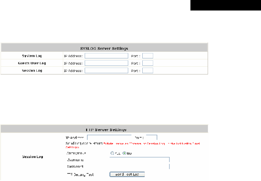
© 2008 4IPNET, INC.
88
4ipnet
MSG
100
User
’
s
Manual
Ÿ SYSLOG Server Settings: Three types of report, including System Log, Guests User Log and Session Log,
can be sent to a specified syslog server.
Ø IP Address: The IP address of the syslog server for receiving the respective reports.
Ø Port: The port number of the IP address.
Ÿ FTP Server Settings: Session logs can be uploaded to a specified FTP server periodically.
Ø Session Log:
o IP Address: The IP address of the FTP server.
o Port: The port number of the FTP server.
o Send Log every Hours: The interval to send session logs, which can be configured in the
Notification E-mail Settings page.
o Anonymous: If No is checked, username and password for accessing the records in the specified
FTP server are required.
o FTP Setting Test: Click Send Test Log to send a test log to verify if the setting is correct.
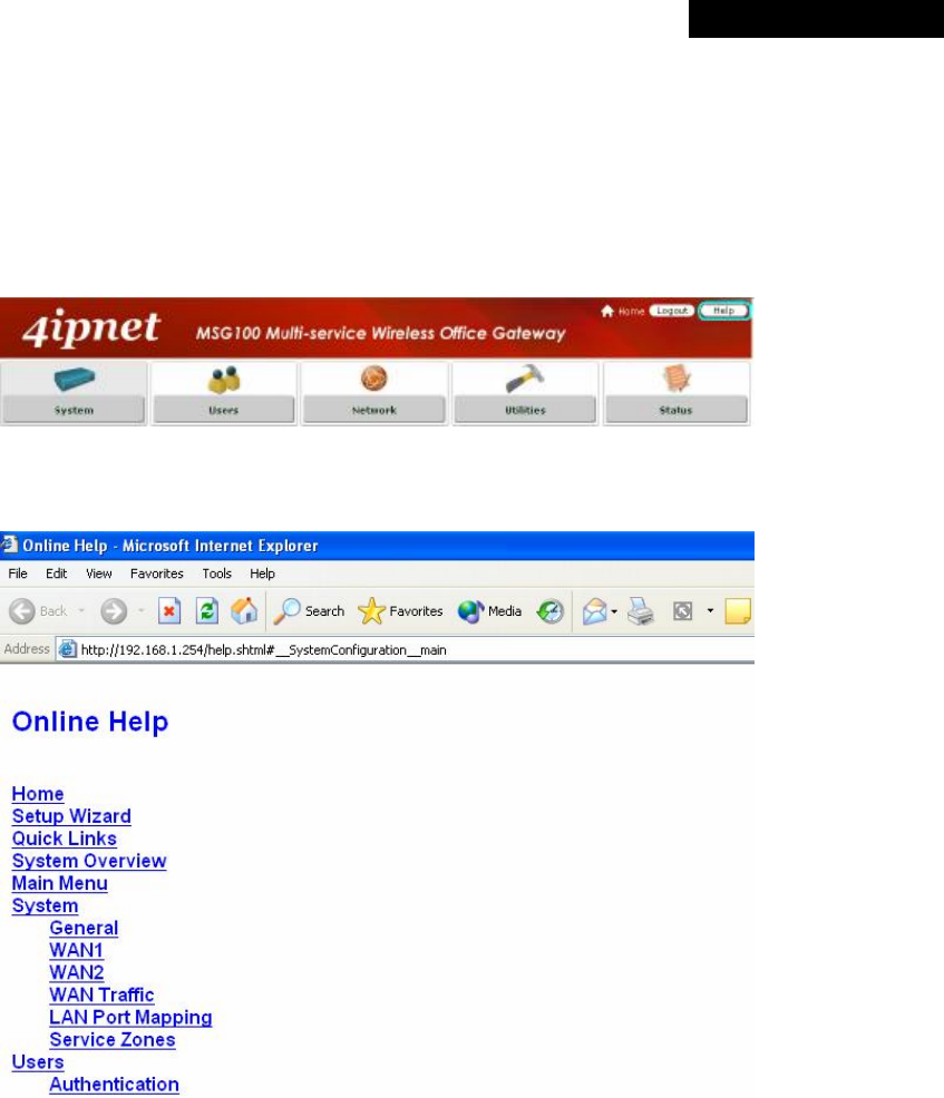
© 2008 4IPNET, INC.
89
4ipnet
MSG
100
User
’
s
Manual
4.6 Help
On the screen, the Help button is at the top right hand corner.
Click Help for the Online Help window and then click the hyperlink of the items for more information.
â
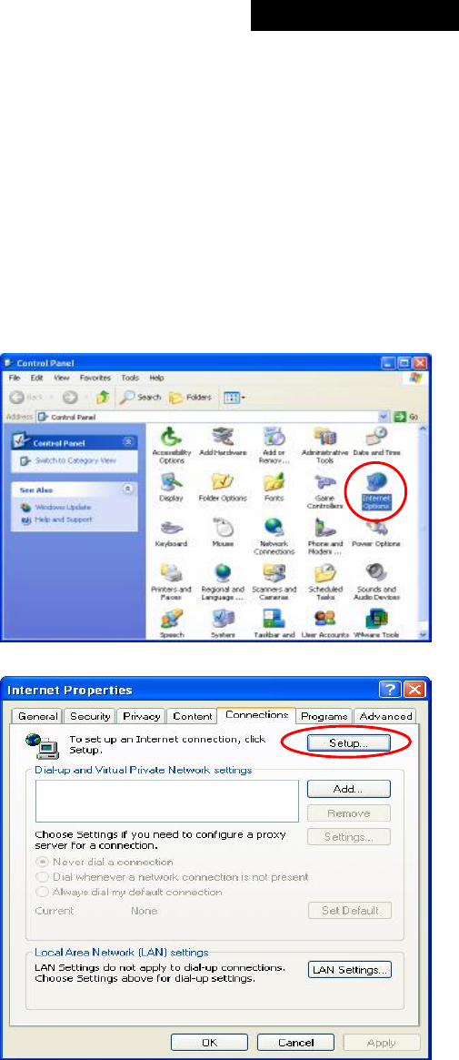
© 2008 4IPNET, INC.
90
4ipnet
MSG
100
User
’
s
Manual
Appendix A. Network Configuration on PC
After MSG100 is installed, the following configurations must be set up on the PC: Internet Connection Setup and
TCP/IP Network Setup.
1. Internet Connection Setup
If the Internet Connection of the client PC has been configured to use local area network, you can skip this
setup. Below shows the setup steps for a PC with Windows XP pre-installed.
Step 1: Choose Start > Control Panel > Internet
Option.
Step 2: Choose the Connections tab, and then
click Setup.
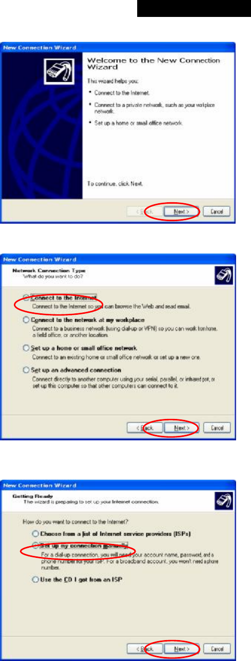
© 2008 4IPNET, INC.
91
4ipnet
MSG
100
User
’
s
Manual
Step 3: When the Welcome to the New
Connection Wizard window appears, click Next.
Step 4: Select “Connect to the Internet” and
then click Next.
Step 5: Select “Set up my connection
manually” and then click Next.
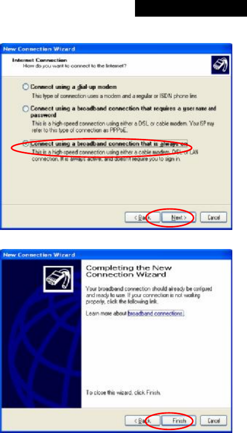
© 2008 4IPNET, INC.
92
4ipnet
MSG
100
User
’
s
Manual
Step 6: Select “Connect using a broadband
connection that is always on” and then click
Next.
Step 7: Finally, click Finish to exit the
Connection Wizard. Now, the setup is completed.
2. TCP/IP Network Setup
By default, MSG100 will assign an appropriate IP address to a client PC configured to use DHCP to obtain IP
addresses automatically. However, you can also use a static IP to connect to MSG100 LAN port. The default
TCP/IP setting of Windows 95/98/2000/XP is “Obtain an IP address automatically”. Please follow the steps
below to check the TCP/IP setting in a PC with Windows XP pre-installed.
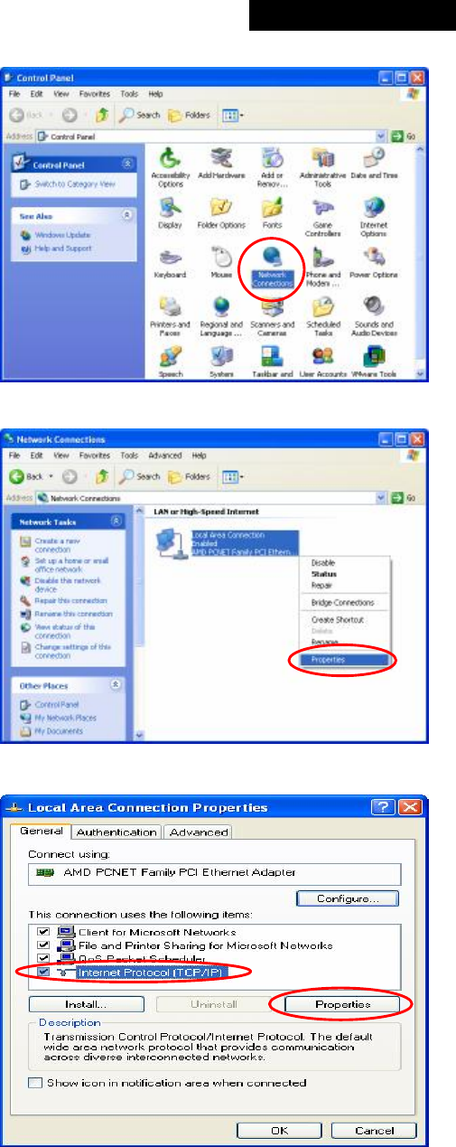
© 2008 4IPNET, INC.
93
4ipnet
MSG
100
User
’
s
Manual
Step 1: Select Start > Control Panel > Network
Connection.
Step 2: Right click on the Local Area
Connection icon and select Properties.
Step 3: Select General tab, and check “Internet
Protocol (TCP/IP)” and then click Properties.
Now, you can choose to use DHCP or a specific IP
address.
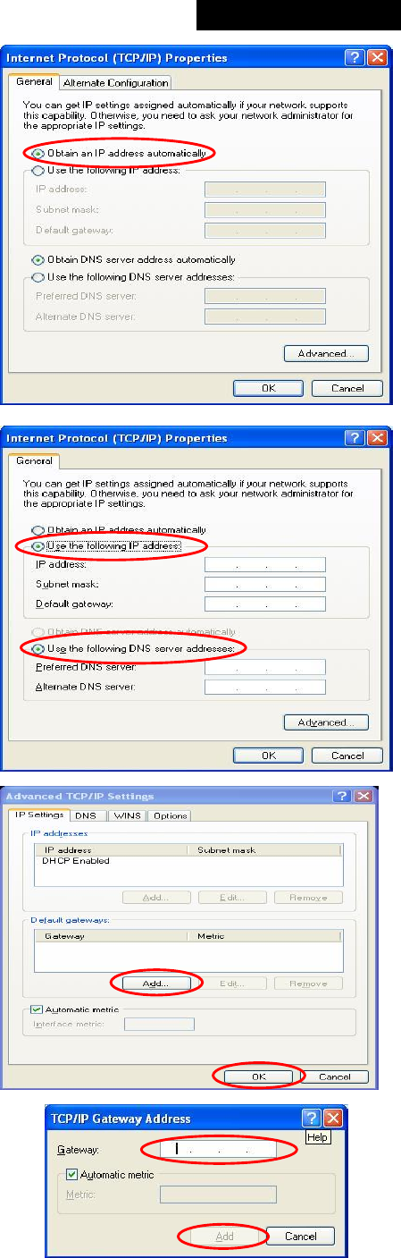
© 2008 4IPNET, INC.
94
4ipnet
MSG
100
User
’
s
Manual
3-1: Using DHCP: If you want to use DHCP, choose
“Obtain an IP address automatically” and click
OK. This is also the default setting of Windows.
Then, reboot the PC to make sure an IP address is
obtained from MSG100.
3-2: Using Specific IP Address: If you want to use a
specific IP address, acquire the following information
from the network administrator: the IP Address,
Subnet Mask and DNS Server address provided by
your ISP and the Gateway address of MSG100.
Choose “Use the following IP address” and enter
the IP address, Subnet mask. If the DNS Server
field is empty, select “Using the following DNS
server addresses” and enter the DNS Server
address. Then, click OK.
Click Advanced to enter the Advanced TCP/IP
Settings window.
Click on the IP Settings tab and click Add below
the “Default gateways” column and the TCP/IP
Gateway Address window will appear.
Enter the gateway address of MSG100 in the “Gateway”
field, and then click Add. After back to the IP Settings tab,
click OK to finish the configuration.
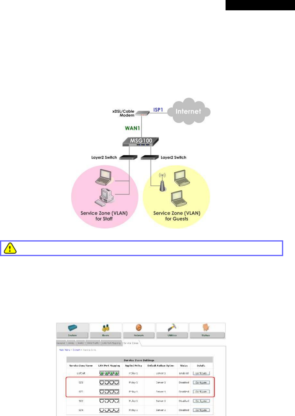
© 2008 4IPNET, INC.
95
4ipnet
MSG
100
User
’
s
Manual
Appendix B. Port-based Service Zone
Deployment Example
In Port-Based mode, each LAN port can only serve traffic from one Service Zone. An example of network
application diagram is shown as below: one Service Zone for Staff and one for Guests.
The switches deployed under MSG100 in Port-Based mode must be Layer 2 switches only.
Configuration Steps for Port-Based Service Zones:
Step 1: Configure Service Zone 1 for Guests
Assume that LAN1 is assigned to the Service Zone 1 (SZ1) for Guests. Click the System menu and select the
Service Zones tab. Click Configure of SZ1.
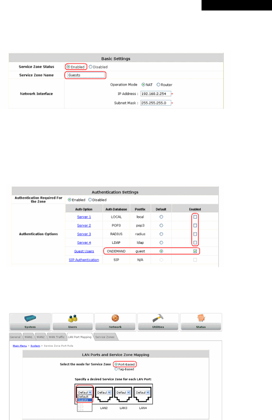
© 2008 4IPNET, INC.
96
4ipnet
MSG
100
User
’
s
Manual
Step 2: Configure Basic Settings for SZ1
Check the Enabled radio button of Service Zone Status to activate SZ1.
Enter a name for SZ1 (e.g. “Guests”) in the Service Zone Name field.
Step 3: Configure Authentication Settings for SZ1
Check the Enabled radio button to enable Authentication Required for the Zone.
Check the Default button and Enabled box of Guest Users to set ONDEMAND authentication method as default.
Disable all other authentication options. Then, click Apply to activate the settings made so far. A warning message
“You should restart the system to activate the changes.” will appear at the bottom of the page. Do NOT restart
the system until you have completed all the configuration steps.
Step 4: Configure LAN Port Mapping for SZ1
Select the LAN Port Mapping tab from the System menu to enter the LAN Ports and Service Zone Mapping
page. Select Guests from the drop-down list box of LAN1. Click Apply to save the selection.
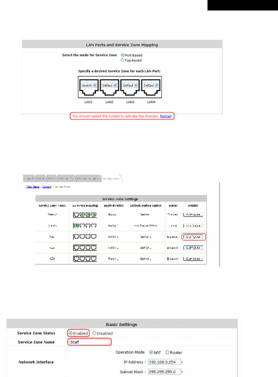
© 2008 4IPNET, INC.
97
4ipnet
MSG
100
User
’
s
Manual
A warning message “You should restart the system to activate the changes.” will appear at the bottom of the
page. Do NOT restart the system until you have completed all the configuration steps.
LAN1 is now configured for Guests.
Step 5: Configure Service Zone 2 for Staff
Assume that LAN2 is assigned to the Service Zone 2 (SZ2) for Staff. Select the Service Zones tab and click
Configure of SZ2.
Step 6: Configure Basic Settings for SZ2
Check the Enabled radio button of Service Zone Status to activate SZ2.
Enter a name for SZ2 (e.g. “Staff”) in the Service Zone Name field.
Step 7: Configure Authentication Settings for SZ2
Check the Enabled radio button to enable Authentication Required for the Zone.
Check the Default button and Enabled box of Server 1 to set LOCAL authentication method as default. Disable all
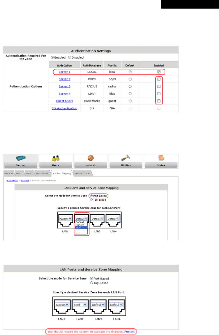
© 2008 4IPNET, INC.
98
4ipnet
MSG
100
User
’
s
Manual
other authentication options. Then, click Apply to activate the settings made so far. A warning message “You
should restart the system to activate the changes.” will appear at the bottom of the page. Do NOT restart the
system until you have completed all the configuration steps.
Step 8: Configure LAN Port Mapping for SZ2
Select the LAN Port Mapping tab from the System menu to enter the LAN Ports and Service Zone Mapping
page. Select Staff from the drop-down list box of LAN2. Click Apply to save the selection.
A warning message “You should restart the system to activate the changes.” will appear at the bottom of the
page. Click the hyperlink of Restart to restart the system and activate all configurations.
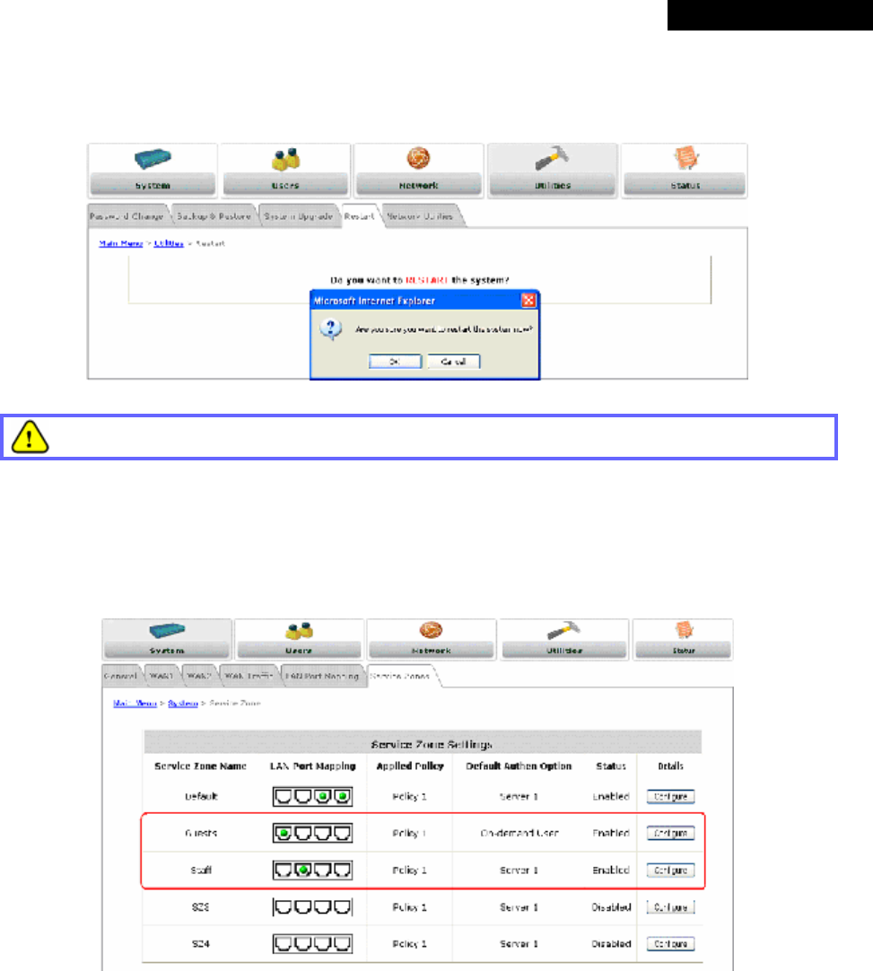
© 2008 4IPNET, INC.
99
4ipnet
MSG
100
User
’
s
Manual
Step 9: Restart the System
A confirmation message of “Do you want to restart the system?” will appear. Click Yes to start the restarting
process. A confirmation dialog box will then pop out. Click OK to continue.
Please do not interrupt the system during the restarting process.
Once the settings of two Service Zones are completed, the configured result will be displayed in the Service Zone
Settings page: SZ1 and SZ2 are both enabled.
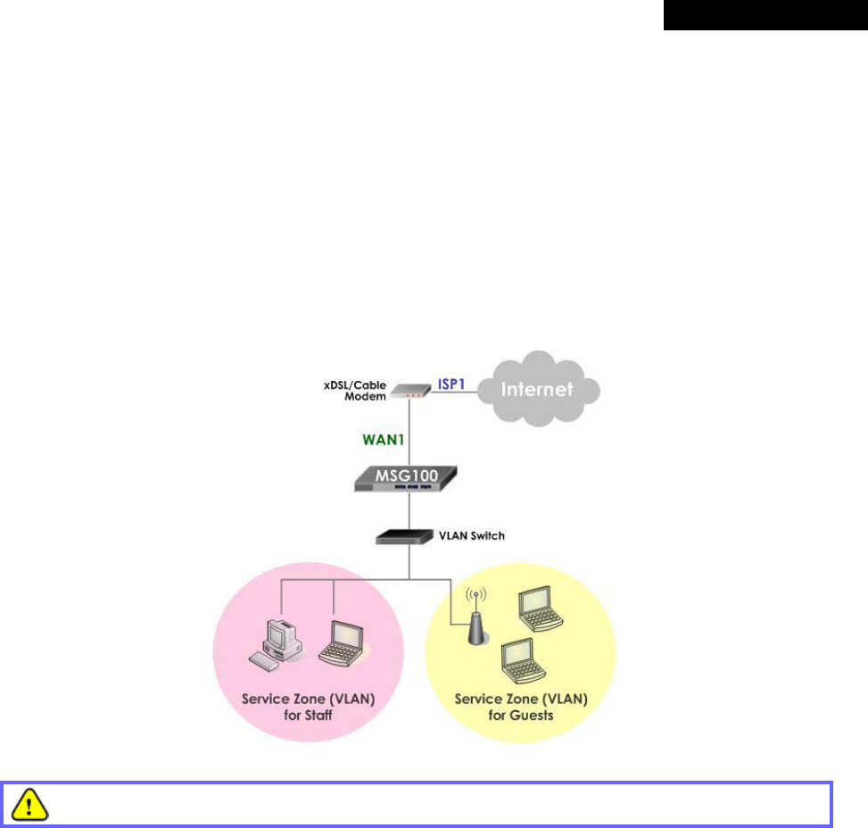
© 2008 4IPNET, INC.
100
4ipnet
MSG
100
User
’
s
Manual
Appendix C. Tag-based Service Zone
Deployment Example
In Tag-Based mode, each LAN port can serve traffic from any Service Zone as each Service Zone is identified by
VLAN tags carried within message frames. An example of network application diagram is shown as below: one
Service Zone for Staff and another for Guests.
The switch deployed under MSG100 in Tag-Based mode must be a VLAN switch only.
Configuration Steps for Tag-Based Service Zones:
The following example assumes the system is in factory default status and just powered up.
Step 1: Set Tag-Based mode
Click the System menu and select the LAN Port Mapping tab. Select Tag-Based mode and
click Apply. A warning message “You should restart the system to activate the changes.”
will appear at the bottom of the page. Do NOT restart the system until you have completed all the
configuration steps.
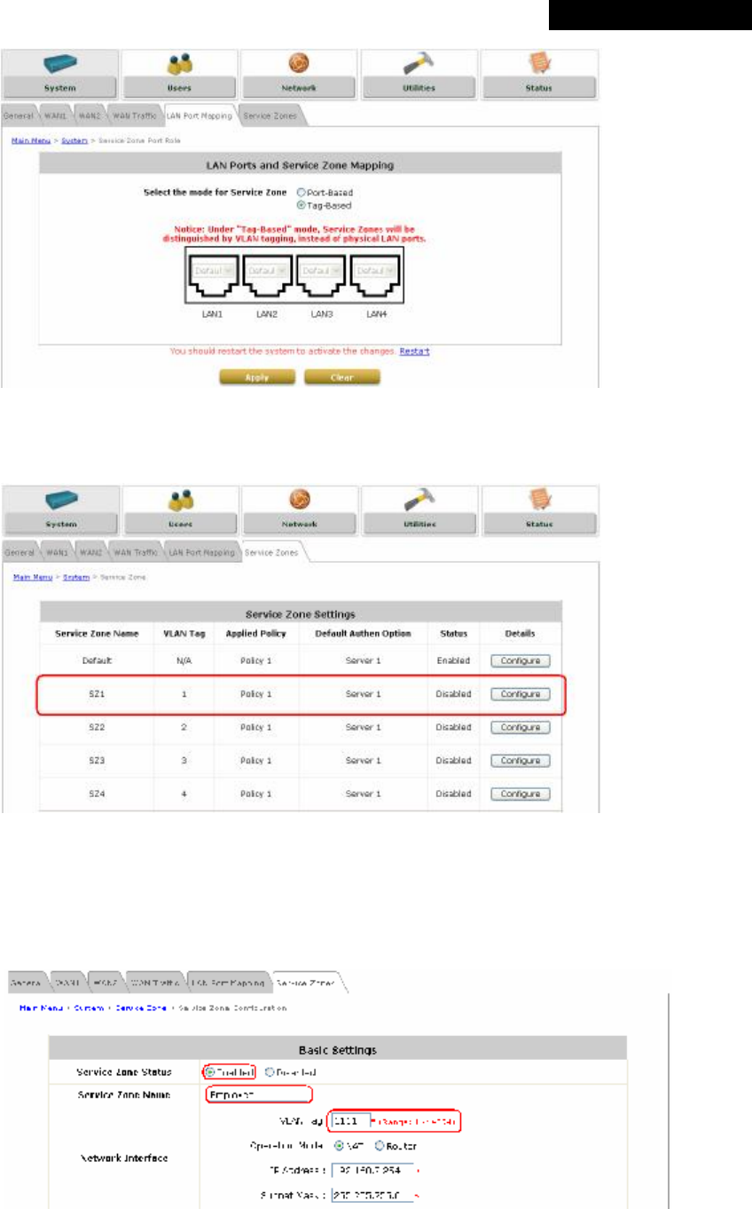
© 2008 4IPNET, INC.
101
4ipnet
MSG
100
User
’
s
Manual
Step 2: Configure Service Zone 1 for Staff
Select the Service Zones tab and click Configure of SZ1.
Step 3: Configure Basic Settings for SZ1
• Check the Enabled radio button of Service Zone Status to activate SZ1.
• Enter a name for SZ1 (e.g. “Employee”) in the Service Zone Name field.
• Enter a VLAN tag for SZ1 (e.g. “1111”) in the VLAN Tag field.
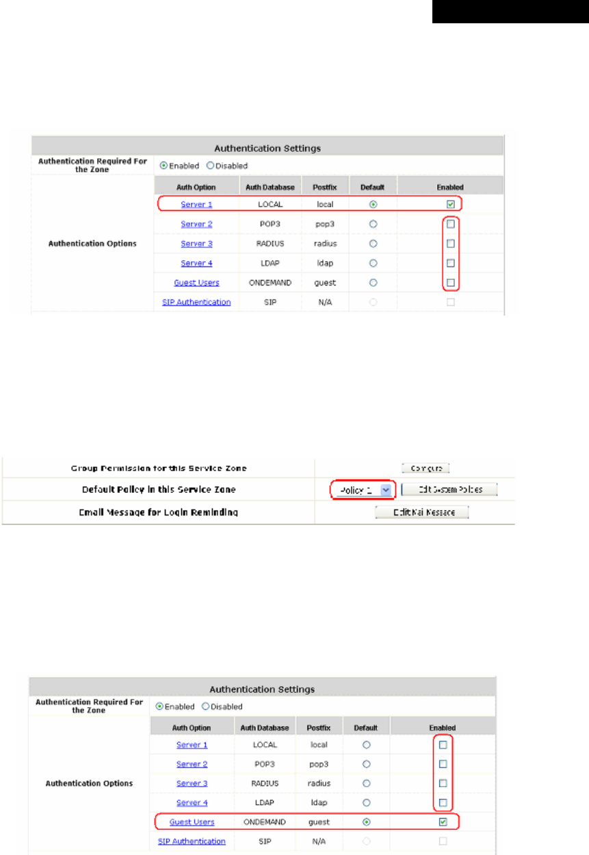
© 2008 4IPNET, INC.
102
4ipnet
MSG
100
User
’
s
Manual
Step 4: Configure Authentication Settings for SZ1
• Check the Enabled radio button to enable Authentication Required for the Zone.
• Check the Default button and Enabled box of Server 1 to set LOCAL authentication method
as default. Disable all other authentication options.
Step 5: Set Policy SZ1
• Select Policy 1 from the drop-down list box.
• Click Apply to activate the settings made so far. A warning message “You should restart
the system to activate the changes.” will appear at the bottom of the page. Do NOT restart
the system until you have completed all the configuration steps.
Step 6: Configure Service Zone 2 for Guests
• Follow Step 2 to Step 5 to configure SZ2.
• In the Authentication Settings section, check the Default button and Enabled box of Guest
Users to set ONDEMAND authentication method as default. Disable all other authentication
options.
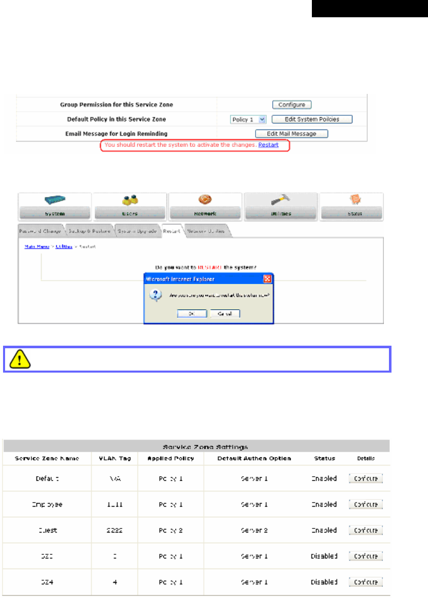
© 2008 4IPNET, INC.
103
4ipnet
MSG
100
User
’
s
Manual
Step 7: Restart the System
• Click Apply to activate the settings. A warning message “You should restart the system to
activate the changes.” will appear at the bottom of the page. Click the hyperlink of Restart
to restart the system and activate all changes you have made.
• A confirmation message of “Do you want to restart the system?” will appear. Click Yes to
start the restarting process. A confirmation dialog box will then pop out. Click OK to continue.
Please do not interrupt the system during the restarting process.
Once the settings of two Service Zones are completed, the configured result will be displayed in
the Service Zone Settings page: SZ1 and SZ2 are both enabled.

© 2008 4IPNET, INC.
104
4ipnet
MSG
100
User
’
s
Manual
Appendix D. Certificate Setting for IE7 and IE6
• Certificate Setting for the Company with Certificate Authority
Any website or high-value Web Applications will require a client to access their websites via Secure Sockets
Layer (SSL). The browser will automatically ask for a public SSL certificate from the website and check if it is
valid. The public SSL Certificate consists of the public key and identity information which can be signed by any
established certificate authority (e.g. VeriSign). The certificate authority guarantees that the public key belongs
to the named entity. Usually, the website’s security certificate encounters a problem only if the security
certificate presented to the browser has not been signed by any trusted certificate authority.
As long as the SSL function is enabled in MSG100, there must be a public SSL certificate signed by an
established certificate authority. To avoid the error message in the browser, a company should have its own
Certificate Authority (CA). The IT department must therefore install the SSL certificate for each normal user
when deploying the MSG100.
Ø Secure Certificate Setting for Both IE7 and IE6
For the company with its own Certificate Authority (CA), the certificate of the company should be trusted
by all its employees’ computers, and the certificate should be delivered through a trusted media. For
example, the MIS staff should install the CA certificate in each employee’s computer. The company’s CA
will issue a certificate for the MSG100 and export it to the MSG100.
• Certificate setting for the company without Certificate Authority
For a company that does not have it own Certificate Authority (CA), the administrator should first create a
certificate either by applying for a trusted one or by certain certificate software. Second, the administrator (as
“trusted CA”) should install this certificate in each client computer through trusted media, and in the meantime,
export this certificate to the MSG100.
In certain condition, the company without Certificate Authority can follow the steps below to avoid the error
messages shown in browser while accessing the system.
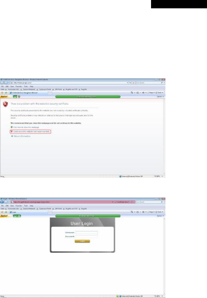
© 2008 4IPNET, INC.
105
4ipnet
MSG
100
User
’
s
Manual
Ø Certificate setting for Internet Explorer 7
o For IE7, the certificate issue may be caused because the certificate publisher is not trusted by
IE7. The following steps may be taken to provide a workaround or to bypass this issue.
Step 1: Open the IE7 browser, and you should be redirected to the default User Login Page. If
the certificate is not trusted, the following page will appear.
Click “Continue to this website”.
Step 2: Next, the default User Login Page will appear, so that clients can login normally.
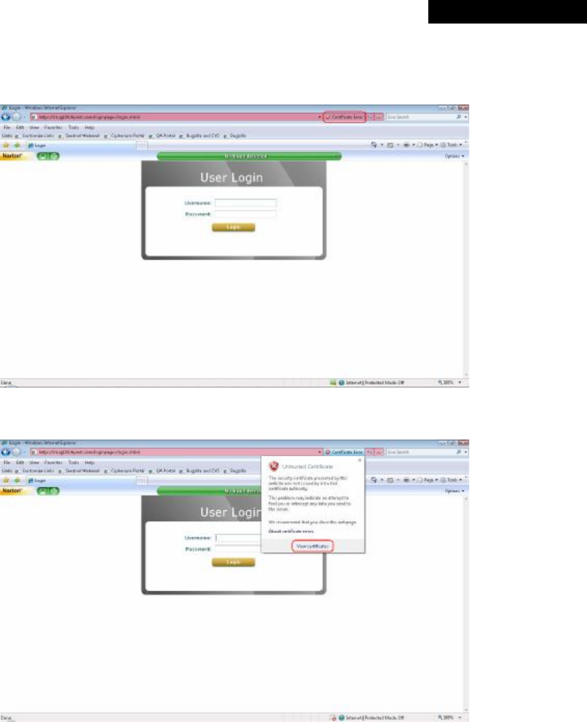
© 2008 4IPNET, INC.
106
4ipnet
MSG
100
User
’
s
Manual
o To install a trusted certificate to solve the IE7 certificate issue, please follow instructions below:
Step 1: When the User Login page appears, click Certificate Error on the top.
Step 2: Click View Certificate.
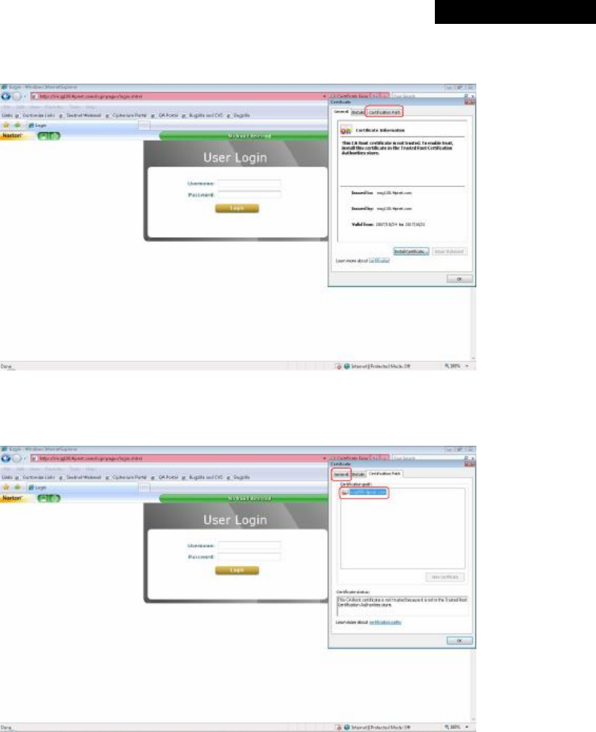
© 2008 4IPNET, INC.
107
4ipnet
MSG
100
User
’
s
Manual
Step 3: Click Certification Path. This is to check whether the certificate is currently in the
correct path.
Step 4: Make sure the certificate path is correct as shown in the following figure. Click OK to
continue.
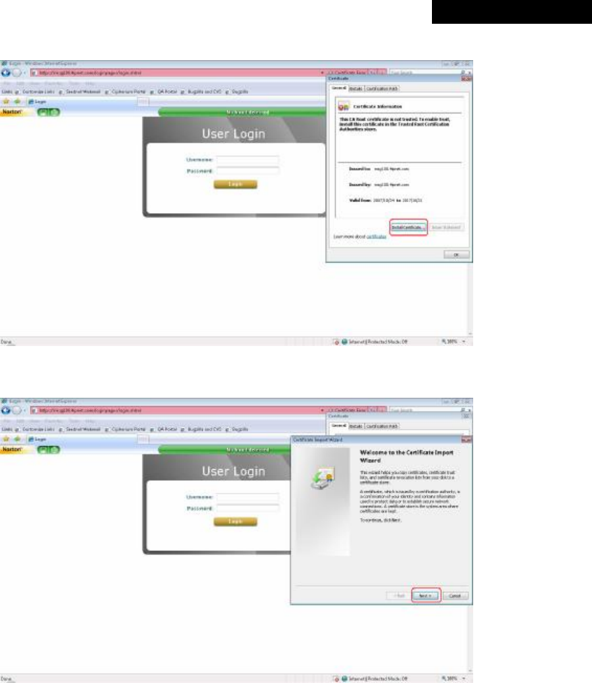
© 2008 4IPNET, INC.
108
4ipnet
MSG
100
User
’
s
Manual
Step 5: Select the General tab. Click Install Certificate to install the certificate.
Step 6: Click Next to continue.
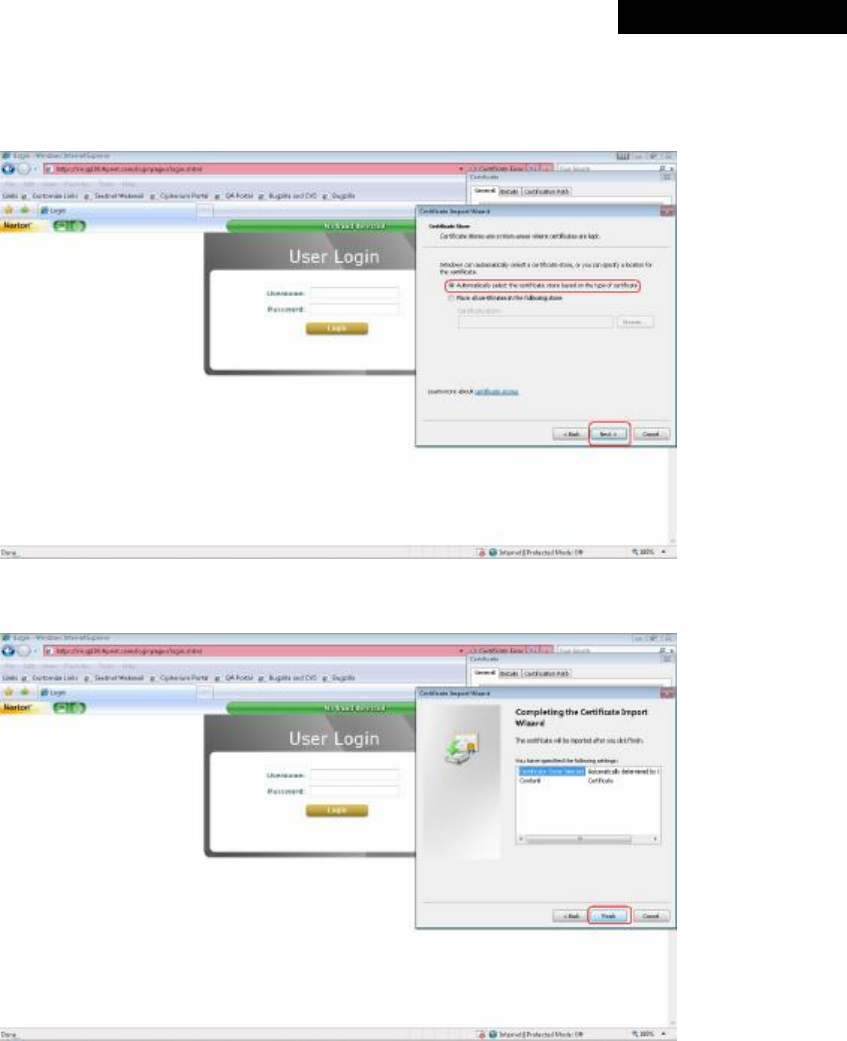
© 2008 4IPNET, INC.
109
4ipnet
MSG
100
User
’
s
Manual
Step 7: Select “Automatically select the certificate store based on the type of certificate”
and then click Next.
Step 8: Click Finish.
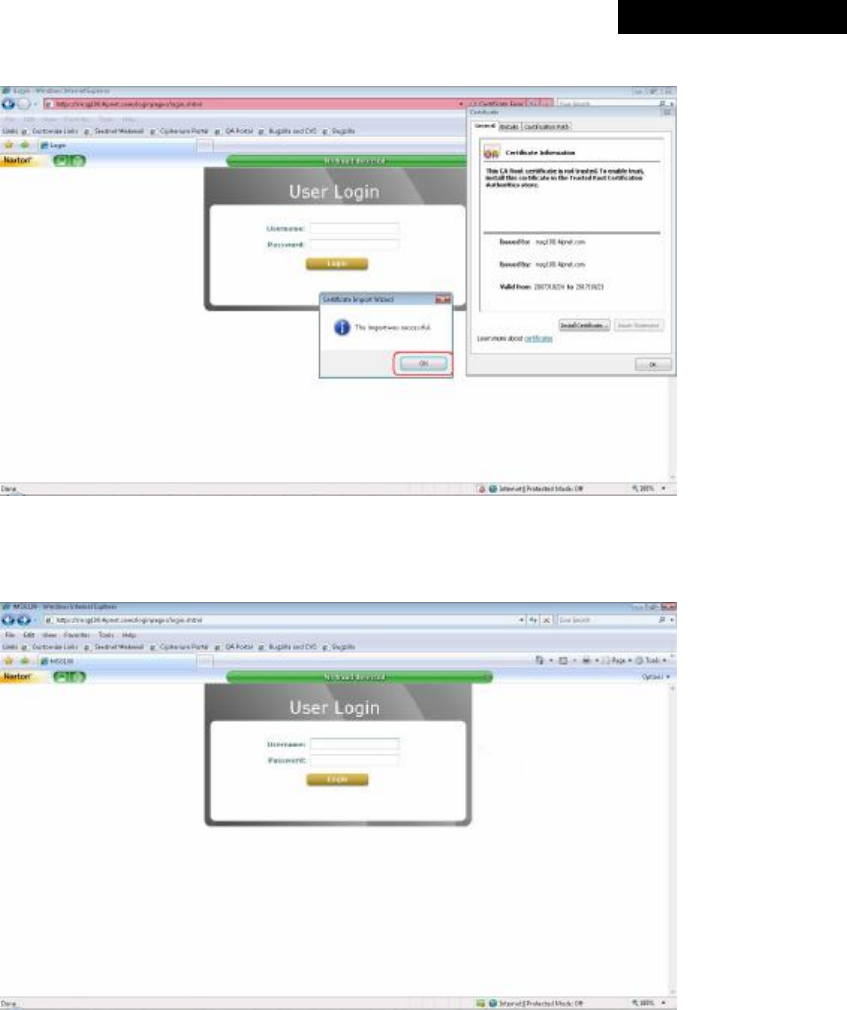
© 2008 4IPNET, INC.
110
4ipnet
MSG
100
User
’
s
Manual
Step 9: Click OK.
Step 10: Launch a new IE7 browser. The key symbol will appear on the top next to the address
field, which means the certificate is now trusted via IE7.
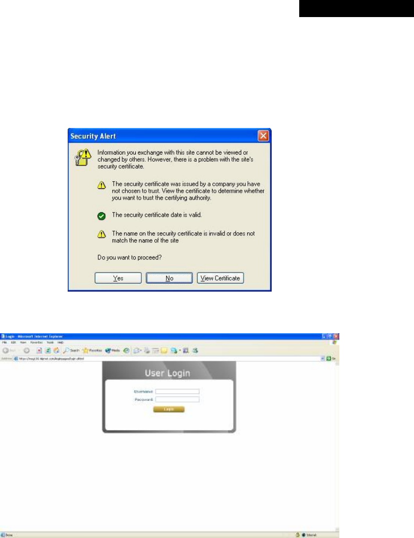
© 2008 4IPNET, INC.
111
4ipnet
MSG
100
User
’
s
Manual
Ø Certificate setting for Internet Explorer 6
For IE6, the certificate issue may be caused because the certificate publisher is not trusted by IE6. The
following steps may be taken to provide a workaround or to bypass this issue.
Step 1: Open an IE6 browser, the Security Alert message will appear if the certificate is not trusted. Click
Yes to bypass this issue and proceed.
Step 2: Next, the User Login Page will appear, so that users can now login normally.
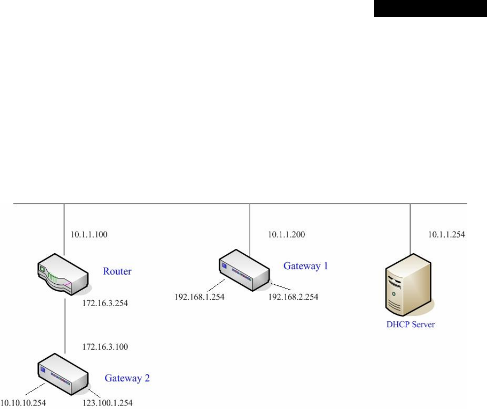
© 2008 4IPNET, INC.
112
4ipnet
MSG
100
User
’
s
Manual
Appendix E. DHCP Replay
MSG100 supports DHCP Relay defined in RFC 3046. When forwarding client-originated DHCP packets to an
external DHCP server, a new option called the “Relay Agent Information option” is inserted by the DHCP relay
agent of MSG100. External DHCP servers that recognize the Relay Agent Information option may use the
information to implement IP address or other parameter assignment policies. The external DHCP server then
echoes the option back to the relay agent in server-to-client replies, and the relay agent strips the option before
forwarding the reply to the client.
An example of connecting 2 gateways with an external DHCP server is shown as below:
Please note that the Router and Gateway 1 connected to the DHCP Server must be under the same network
segment as DHCP Server.
When a client requests an IP address from Gateway 1 through the build-in DHCP relay agent of MSG100, the
DHCP server will receive a DHCP REQUEST packet with Option 82 (a code defined in RFC 3046). Also a Circuit
ID will be sent by MSG100 when DHCP relay is enabled to define where the packet is sent from, and this Circuit ID
must have a format of MAC_IP, such as 00:E0:22:DF:AC:DF_192.168.1.254. Therefore, when the external DHCP
server gets the request packet, it knows where to reply and which IP to assign.
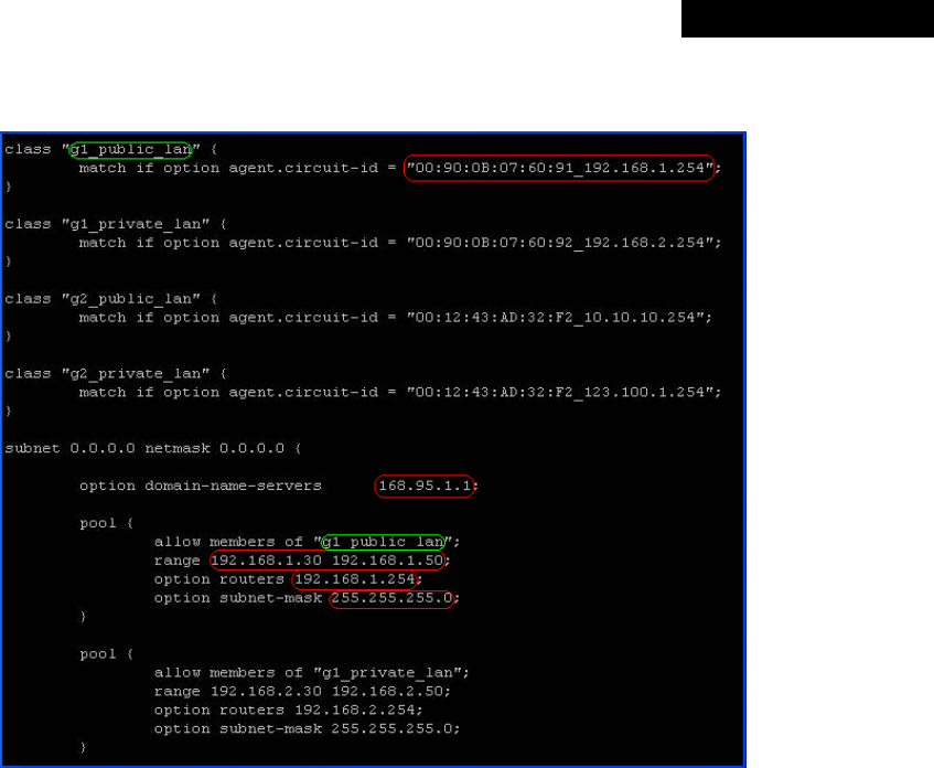
© 2008 4IPNET, INC.
113
4ipnet
MSG
100
User
’
s
Manual
Here is an example of configuration file of the DHCP server:
From the file, a client that connects to MSG100 sends out a DHCP request. DHCP relay function in MSG100 is
enabled and sending a Circuit ID 00:90:0B:07:60:91_192.168.1.254 to the external DHCP server. When DHCP
server gets the Circuit ID, it recognizes that the request is sent from g1_public_lan and thus assigns the client a
DNS server of 169.95.1.1, an IP that can be in the range of 192.168.1.30 and 192.168.1.50, a default gateway of
192.168.1.254, and a subnet-mask of 255.255.255.0.
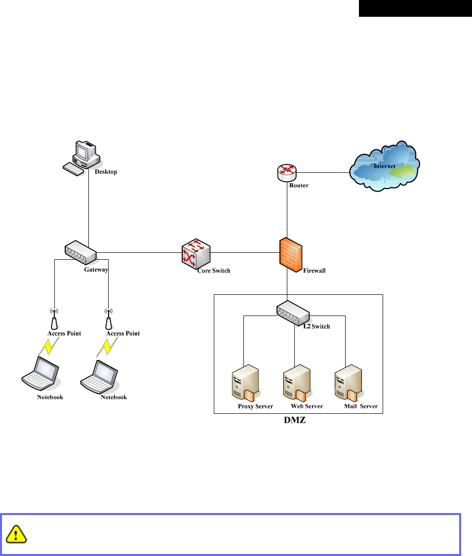
© 2008 4IPNET, INC.
114
4ipnet
MSG
100
User
’
s
Manual
Appendix F. Proxy Setting for Enterprise
Enterprises usually isolate their intranet and the Internet by using more elaborated network architecture. Many
enterprises have their own proxy server which is usually at the intranet or DMZ under firewall protection.
In enterprises, network managers or MIS staff may often ask their users to enable the proxy setting of their
browsers (e.g. IE and Firefox) to reduce Internet access loading. Therefore, the proxy setting in MSG100 must
be configured.
Some enterprises will automatically redirect packets to a proxy server by using core switches or
Layer 7 devices. Therefore, clients don’t need to enable the proxy setting of their browsers, and the
administrator doesn’t need to configure any proxy setting in this system.
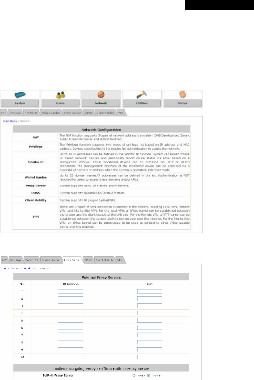
© 2008 4IPNET, INC.
115
4ipnet
MSG
100
User
’
s
Manual
Please follow the steps below to complete the proxy configuration:
Ø Gateway setting
Step 1: Log in to the Main Menu of the web management interface.
Step 2: Click on the Network menu to enter the homepage of Network.
Step 3: Select the Proxy Server tab to enter the External Proxy Server page.
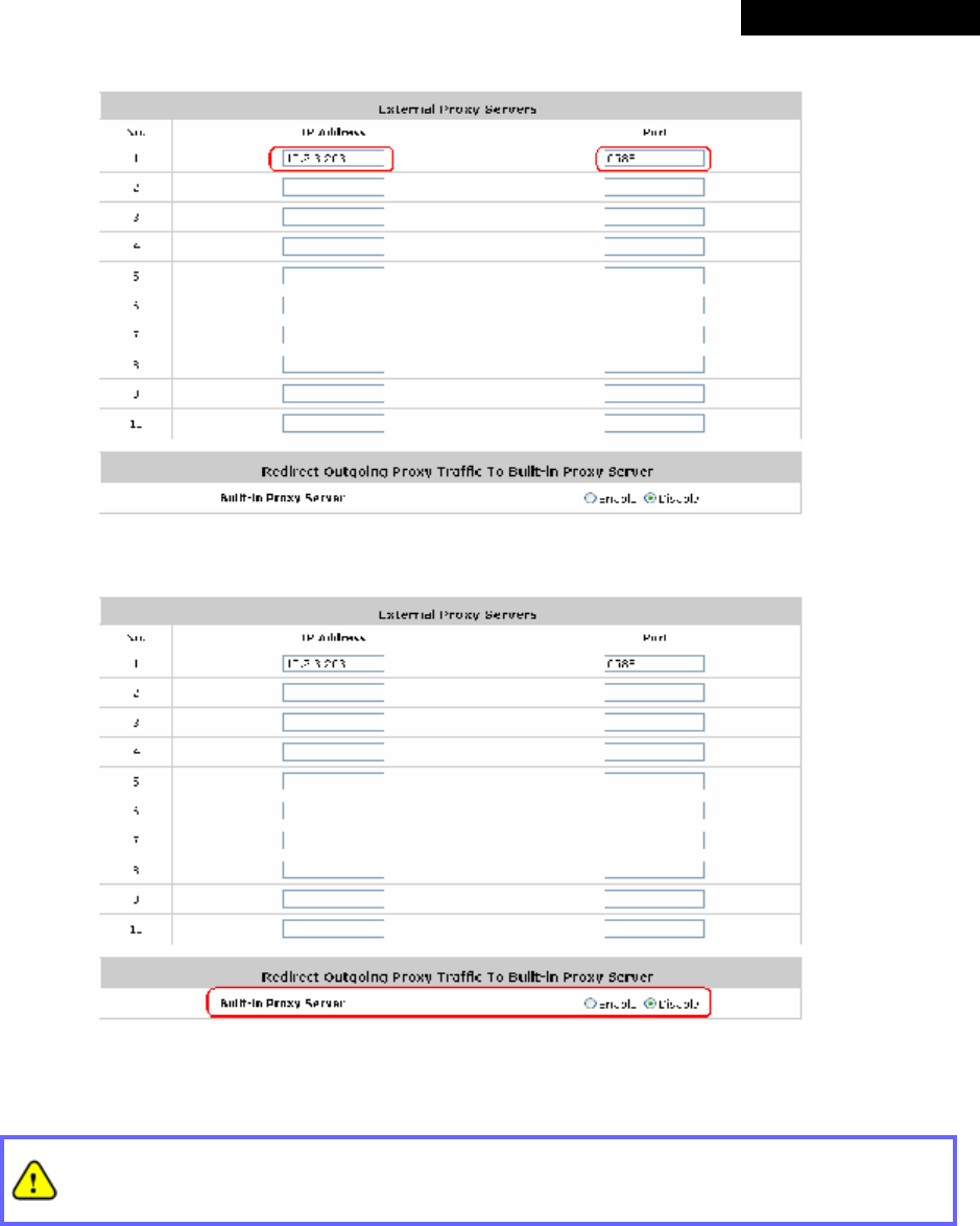
© 2008 4IPNET, INC.
116
4ipnet
MSG
100
User
’
s
Manual
Step 4: Enter the IP address and port number of your proxy Server in the IP Address and Port fields.
Step 5: Disable the Built-in Proxy Server.
Step 6: Click Apply to save the settings.
If your proxy server is disabled, it will cause a problem with the user authentication operation.
When users open a browser, the login page won’t appear because that proxy server is down.
Please make sure your proxy server is always available.
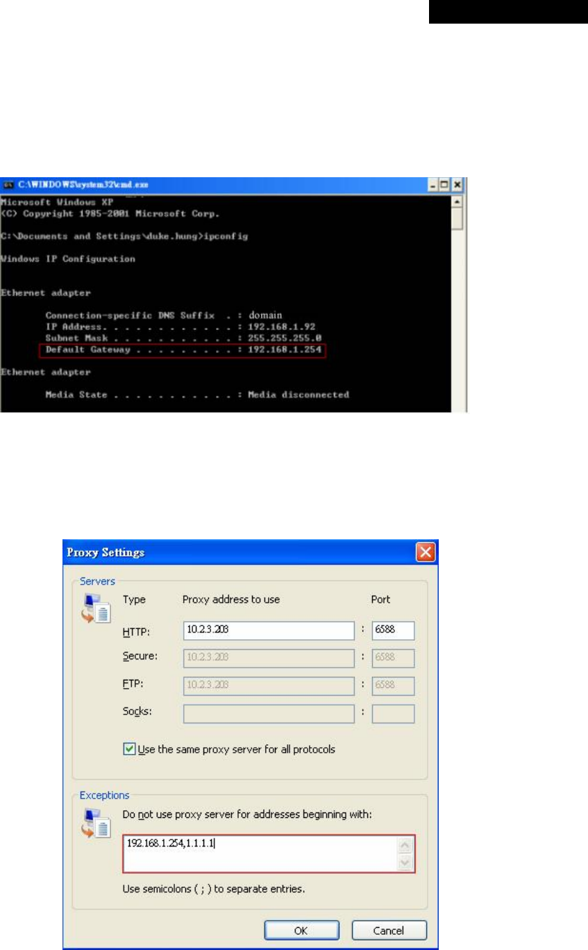
© 2008 4IPNET, INC.
117
4ipnet
MSG
100
User
’
s
Manual
Ø Client setting
It is necessary for clients to specify the default gateway IP address in the proxy exceptions box, so that
the user login successful page can show up normally.
Step 1: Use command “ipconfig” to get Default Gateway IP Address.
Step 2: Open a browser to specify the default gateway IP address (e.g. 192.168.1.254) and logout page
IP address “1.1.1.1” in the proxy exceptions box.
o For I.E
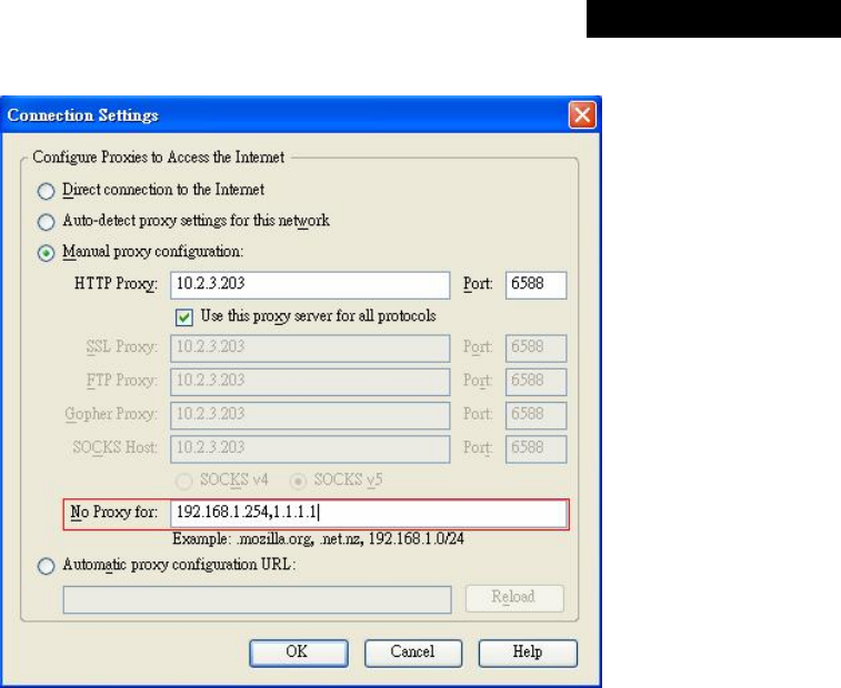
© 2008 4IPNET, INC.
118
4ipnet
MSG
100
User
’
s
Manual
o For Firefox
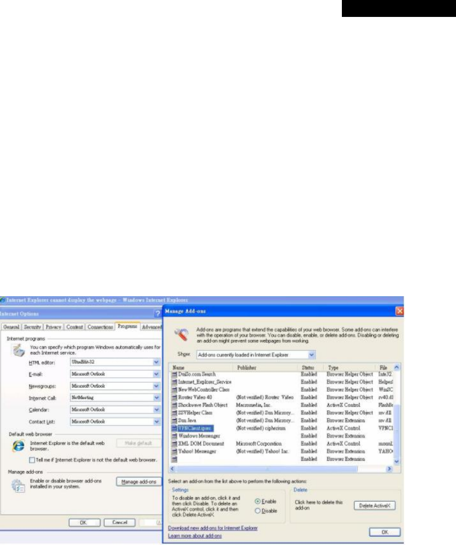
© 2008 4IPNET, INC.
119
4ipnet
MSG
100
User
’
s
Manual
Appendix G. IPSec VPN
MSG100 supports IPSec VPN for clients with Windows XP SP2 (with patch) and Windows 2000. To fully utilize the
nature supported IPSec VPN by Microsoft Windows XP SP2 (with patch) and Windows 2000 operating systems,
MSG100 implements IPSec VPN tunnels between clients and MSG100 itself, no matter through wired or wireless
network.
By pushing down an ActiveX to clients from MSG100, no extra client software needs to be installed except the
ActiveX, where a so-called “clientless” IPSec VPN setting will be configured automatically. Upon completion of the
setup, a build-in IPSec VPN feature is enabled and ready to serve.
• ActiveX Component
The ActiveX is a software component running inside Internet Explorer. The ActiveX component can be checked
by the following windows.
Windows Internet Explorer: From the Tools menu, click on Internet Options. Select the Programs tab and
click Manage add-ons button to enter the Manage add-ons dialogue box, where you can see
VPNClient.ipsec is enabled.
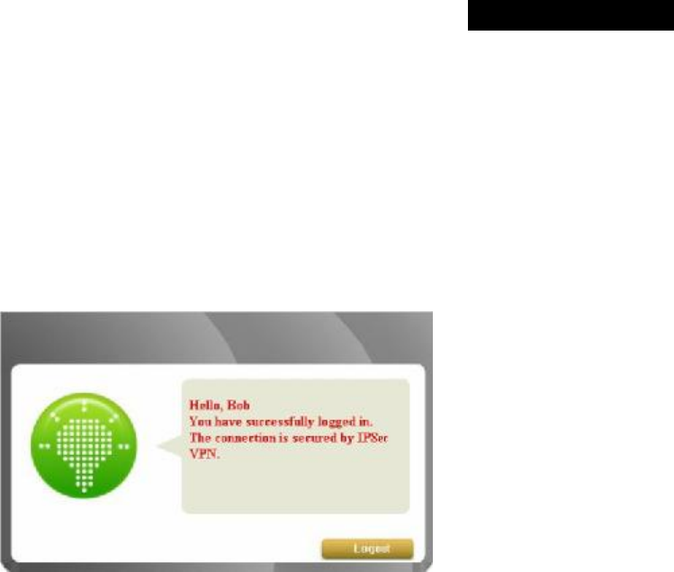
© 2008 4IPNET, INC.
120
4ipnet
MSG
100
User
’
s
Manual
During the first-time login to MSG100, Internet Explorer will ask clients to download an ActiveX component of
IPSec VPN. Once this ActiveX component is downloaded, it will run in parallel with the “Login Success Page”
after the page being brought up successfully. The ActiveX component helps set up individual IPSec VPN
tunnels between clients and MSG100 and check the validity of IPSec VPN tunnels between them. If the
connection is down, the ActiveX component will detect the broken link and decompose the IPSec tunnel. Once
the IPSec VPN tunnel was built, all sent packets will be encrypted. Without connecting to the original IPSec
VPN tunnel, a client has no alternative way to gain network connection beyond this. IPSec VPN feature
supported by MSG100 directly solves possible data security leak problem between clients and the system via
either wireless or wired connections without extra hardware or client software installed.
• Limitations
The limitation on the client side due to ActiveX and Windows OS includes:
Ø Internet Connection Firewall of Windows XP or Windows XP SP1 is not compatible with IPSec protocol.
It shall be turned off to allow IPSec packets to pass through.
Ø Without patch, ICMP (Ping) and PORT command of FTP can not work in Windows XP SP2.
Ø The Forced termination (through CTRL+ALT+DEL, Task Manager) of the Internet Explorer will stop the
running of ActiveX. It causes that IPSec tunnel cannot be cleared properly at client device. A reboot of
client device is needed to clear the IPSec tunnel.
Ø The crash of Windows Internet Explorer may cause the same result.
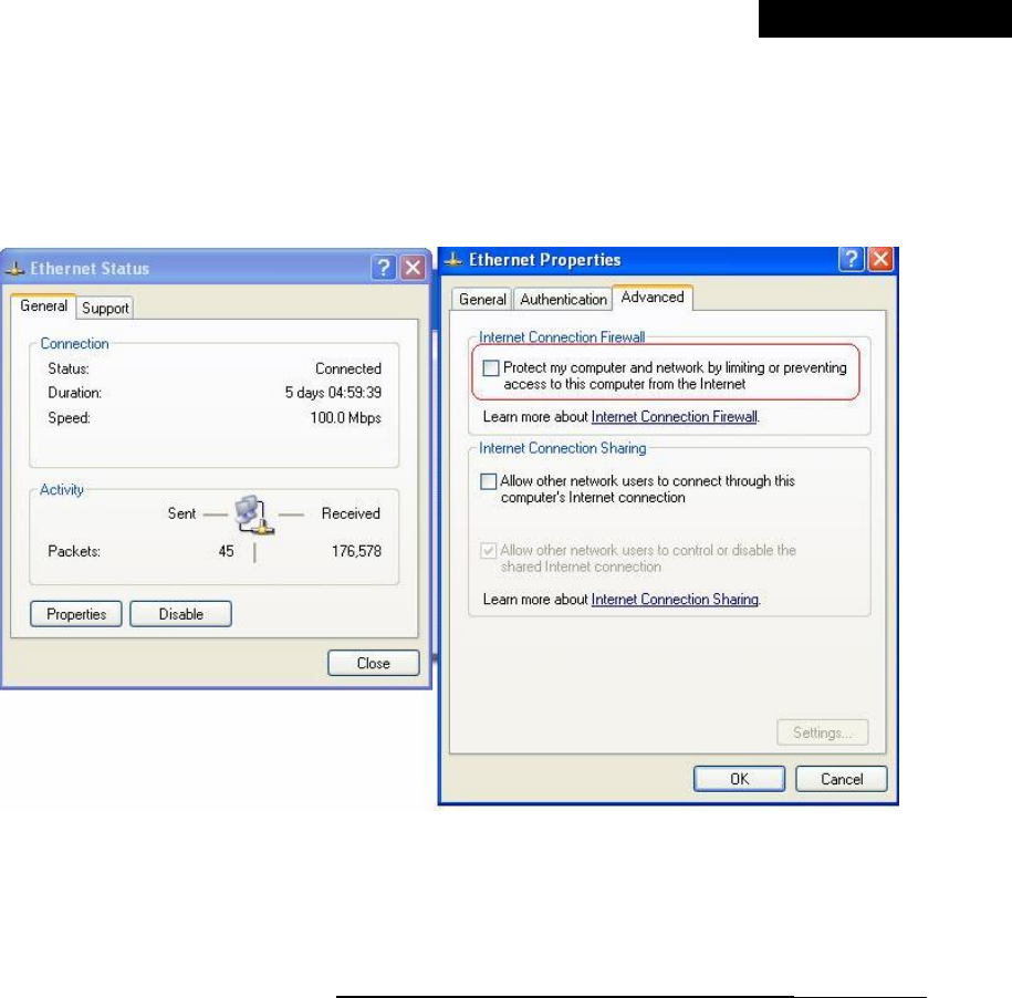
© 2008 4IPNET, INC.
121
4ipnet
MSG
100
User
’
s
Manual
• Internet Connection Firewall
In Windows XP and Windows XP SP1, the Internet Connection Firewall is not compatible with IPSec. Internet
Connection Firewall will drop packets from tunneling of IPSec VPN. Please TURN OFF Internet Connection
Firewall feature or upgrade the Windows OS into Windows XP SP2.
• ICMP and Active Mode FTP
In Windows XP SP2 without patching by KB889527, it will drop ICMP packets from IPSec tunnel. This problem
can be fixed by upgrading patch KB889527. Before enabling IPSec VPN function on client devices, please
access the patch from Microsoft’s web at http://support.microsoft.com/default.aspx?scid=kb;en-us;889527.
This patch also fixes the problem of supporting active mode FTP inside IPSec VPN tunnel of Windows XP SP2.
Please UPDATE clients’ Windows XP SP2 with this patch.
• The Termination of ActiveX
The ActiveX component for IPSec VPN is running in parallel with the web page of “Login Success”. To ensure
that the built-in IPSec VPN tunnel is always alive, unless clients decide to close the session and to disconnect
from MSG100, the following conditions or behaviors, which may cause the Internet Explorer to stop the
ActiveX, should be avoided.
(1) The crash of Internet Explorer on running ActiveX.
If it happens, please reboot the client computer. Once Windows service is resumed, go through the login
process again.
(2) Termination of the Internet Explorer Task from Windows Task Manager.
Do NOT terminate this VPN task of Internet Explorer.
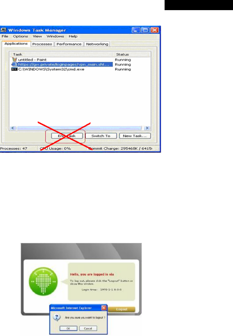
© 2008 4IPNET, INC.
122
4ipnet
MSG
100
User
’
s
Manual
(3) Execution of instructions given by the following Windows messages:
† Close the Windows Internet Explorer.
† Click Logout on Login Success page.
† Click Back or Refresh of the same Internet Explorer browser page.
† Enter a new URL in the same Internet Explorer browser page.
† Open a URL from the other application (e.g. email of Outlook) that occupies this existing Internet
Explorer.
Click Cancel if you do not intend to stop the IPSec VPN connection.
• Non-supported OS and Browser
In current version, Windows Internet Explorer is the only browser supported by MSG100. Windows XP,
Windows 2000, and Windows Vista are the supported OS.
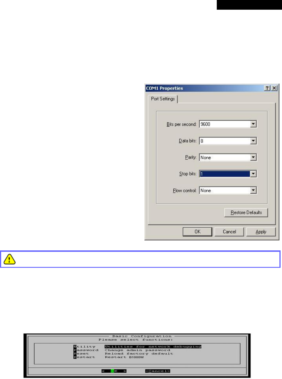
© 2008 4IPNET, INC.
123
4ipnet
MSG
100
User
’
s
Manual
Appendix H. Console Interface
The administrator can enter the console interface via this port to handle problems occurring during operation.
Certain system status such as boot-up time, firmware version and interface status can be found in this console
interface.
1. To connect the console port of MSG100, you need a
console cable and a terminal simulation program, such
as the Hyper Terminal.
2. If you use Hyper Terminal, please set the parameters
as follows:
Bits per second: 9600
Data bits: 8
Parity: None
Stop bits: 1
Flow control: None
The main console is a menu-driven text interface with dialog boxes. Please use arrow keys on the
keyboard to browse the menu and press the Enter key to make selection or confirm inputs.
3. Once the console port of MSG100 is connected properly, the console main screen will appear automatically. If
the screen does not appear in the terminal simulation program automatically, try to press the arrow keys, so
that the terminal simulation program will send some messages to the system and the welcome screen or the
main menu should appear. If you are still unable to see the welcome screen or the main menu of the console,
please check the connection of the console cables and the settings of the terminal simulation program.
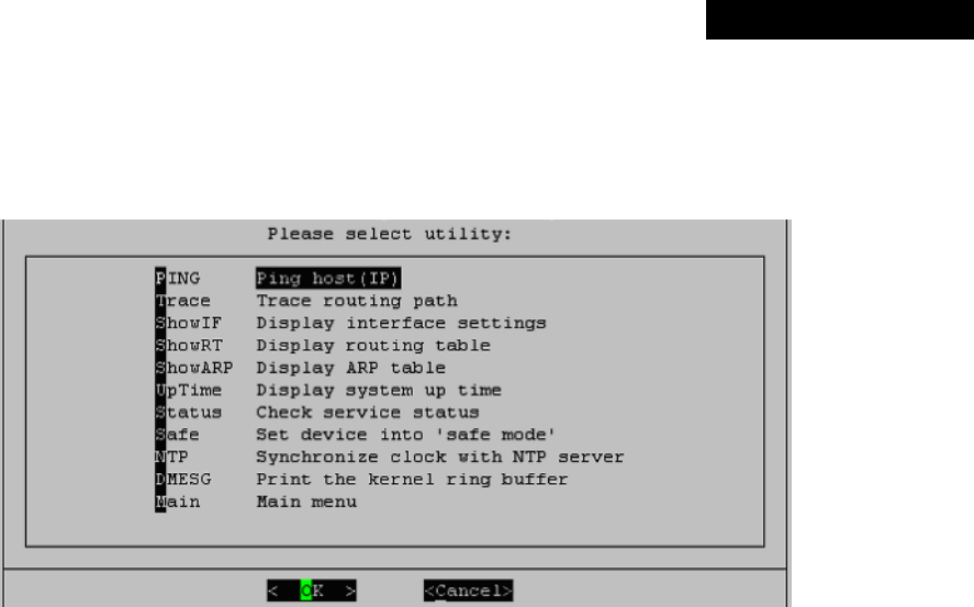
© 2008 4IPNET, INC.
124
4ipnet MSG100 User’s Manual
Ÿ Utilities for network debugging
The console interface provides several utilities to assist the administrator to check the system conditions and to
debug problems. The utilities are described as follows:
Ø Ping host (IP): By sending ICMP echo request to a specified host and wait for the response to test the
network status.
Ø Trace routing path: Trace and inquire the routing path to a specific target.
Ø Display interface settings: It displays the information of each network interface setting including the
MAC address, IP address, and netmask.
Ø Display the routing table: The internal routing table of the system is displayed, which may help to
confirm the Static Route settings.
Ø Display ARP table: The internal ARP table of the system is displayed.
Ø Display system up time: The system live time (time for system being turn on) is displayed.
Ø Check service status: Check and display the status of the system.
Ø Set device into “safe mode”: If the administrator is unable to use Web Management Interface via the
browser for the system failed inexplicitly. The administrator can choose this utility and set MSG100 into
safe mode, and then the administrator can manage this device with browser again.
Ø Synchronize clock with NTP server: Immediately synchronize the clock through the NTP protocol and
the specified network time server. Since this interface does not support manual setup for its internal
clock; therefore, the administrator must reset the internal clock through the NTP.
Ø Print the kernel ring buffer: It is used to examine or control the kernel ring buffer. The program helps to
print out their boot-up messages instead of copying the messages by hand.
Ø Main menu: Go back to the main menu.

© 2008 4IPNET, INC.
125
4ipnet MSG100 User’s Manual
Ÿ Change admin password
The default username and password are both “admin”, the same setting for web management interface. You
can use this option to change the system administrator password. Even if you forget the password and are
unable to log in the web management interface or the remote end of the SSH, you can still use the null modem to
connect the console management interface and set the administrator password again.
Ÿ Reload factory default
Choosing this option will reset the system configuration to the factory defaults.
Ÿ Restart MSG100
Choosing this option will restart MSG100.

© 2008 4IPNET, INC.
126
4ipnet
MSG
100
User
’
s
Manual
Appendix I. Session Limit and Session Log
• Session Limit
To prevent ill-behaved clients or malicious software from using up system’s connection resources, the
administrator will have to restrict the number of concurrent sessions that a user can establish.
Ø The maximum number of concurrent sessions (TCP and UDP) for each user can be specified in the policy
setting, which can be chosen to apply to all users including authenticated users, users on non-
authenticated ports, privileged users, and clients in virtual server and DMZ zones.
Ø When the number of a user’s sessions reaches the session limit (a choice of Unlimited, 10, 25, 50, 100,
200, 350, and 500), the user will be implicitly suspended upon receipt of any new connection request. In
this case, a record will be logged to the Syslog server specified in the Email & SYSLOG.
Ø Since this basic protection mechanism may not be able to protect the system from all malicious DoS
attacks, it is strongly recommended to build some immune capabilities (such as IDS or IPS solutions) in
the network deployment to protect the network in daily operation.
• Session Log
The system can record connection details of each client while accessing the Internet. In addition, the log data
can be sent out to a specified Syslog Server, Email Box or FTP Server based on pre-defined interval time.
Ø The following table shows the fields of a session log record.
Field Description
Date and Time The date and time that the session is established
Session Type [New]: This is a newly established session.
[Blocked]: This session is blocked by a Firewall rule.
Username
The account name (with postfix) of the user. When it shows “N.A.”, it
indicates that the user or device does not need to log in with a
username, for example, the user or device is on a non-authenticated
port or on the privileged MAC/IP list. Change the account name
accordingly, if the name is not identifiable in the record.
8 Note: Only 31 characters are allowed for the combination of
Session Type plus Username.
Protocol The communication protocol of session: TCP or UDP
MAC The MAC address of the client computer or device
SIP The source IP address of the client computer or device
SPort The source port number of the client computer or device
DIP The destination IP address of the client computer or device
DPort The destination port number of the client computer or device

© 2008 4IPNET, INC.
127
4ipnet
MSG
100
User
’
s
Manual
Ø An example of session log data is shown as below:
Aug 30 12:35:05 2007 [New]user1@local TCP MAC=00:09:6b:cd:83:8c SIP=10.1.1.37 SPort=1626 DIP=203.125.164.132 DPort=80
Aug 30 12:35:05 2007 [New]user1@local TCP MAC=00:09:6b:cd:83:8c SIP=10.1.1.37 SPort=1627 DIP=203.125.164.132 DPort=80
Aug 30 12:35:06 2007 [New]user1@local TCP MAC=00:09:6b:cd:83:8c SIP=10.1.1.37 SPort=1628 DIP=203.125.164.142 DPort=80
Aug 30 12:35:06 2007 [New]user1@local TCP MAC=00:09:6b:cd:83:8c SIP=10.1.1.37 SPort=1629 DIP=203.125.164.142 DPort=80
Aug 30 12:35:07 2007 [New]user1@local TCP MAC=00:09:6b:cd:83:8c SIP=10.1.1.37 SPort=1630 DIP=67.18.163.154 DPort=80
Aug 30 12:35:09 2007 [New]user1@local TCP MAC=00:09:6b:cd:83:8c SIP=10.1.1.37 SPort=1631 DIP=202.43.195.52 DPort=80
Aug 30 12:35:10 2007 [New]user1@local TCP MAC=00:09:6b:cd:83:8c SIP=10.1.1.37 SPort=1632 DIP=203.84.196.242 DPort=80
P/N: V10020080124