4IPNET WHG301L001 WLAN Controller User Manual 1 of 2
4IPNET, INC. WLAN Controller 1 of 2
UserManual.wiki
>
4IPNET
>
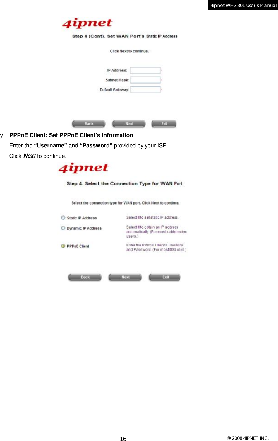
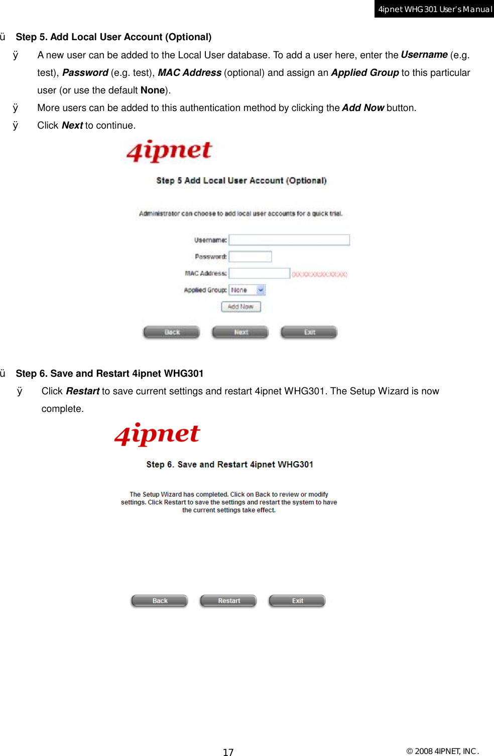
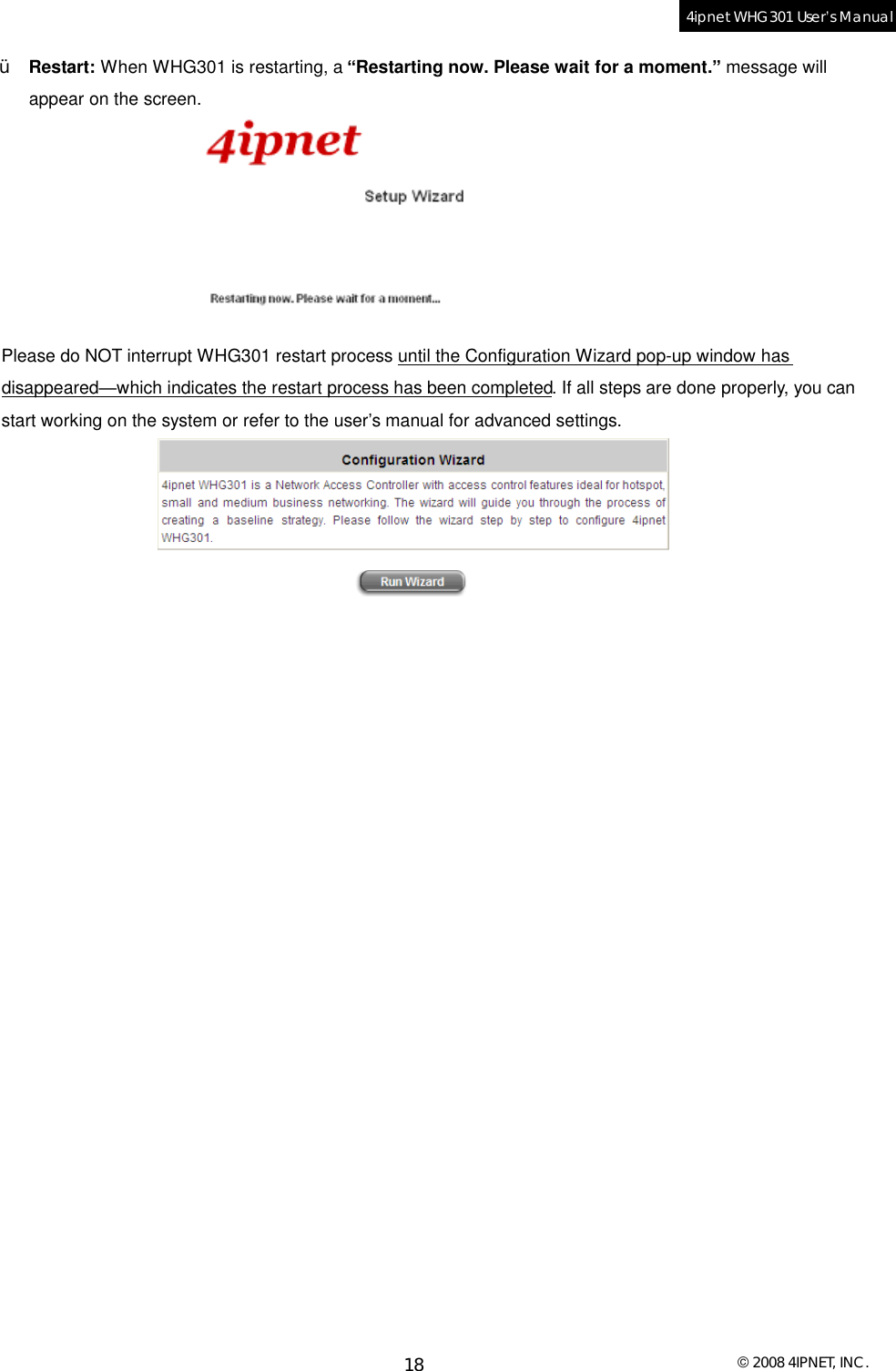
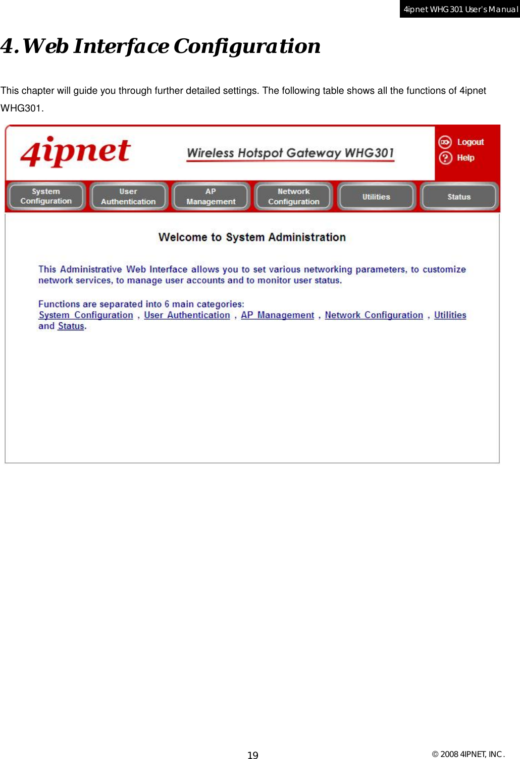
WHG301L001 User Manual
>
User manual 1 of 2
Contents
1.
User manual 1 of 2
2.
User manual 2 of 2
User manual 1 of 2
Navigation menu
Upload a User Manual
Namespaces
Wiki Guide
HTML
PDF
Info
Views
User Manual
Discussion / Help
Navigation