4RF SI902M160 900 MHz Band Frequency Hopping Radio User Manual Aprisa SRi 1 0 0
4RF Limited 900 MHz Band Frequency Hopping Radio Aprisa SRi 1 0 0
UserManual.wiki
>
4RF
>
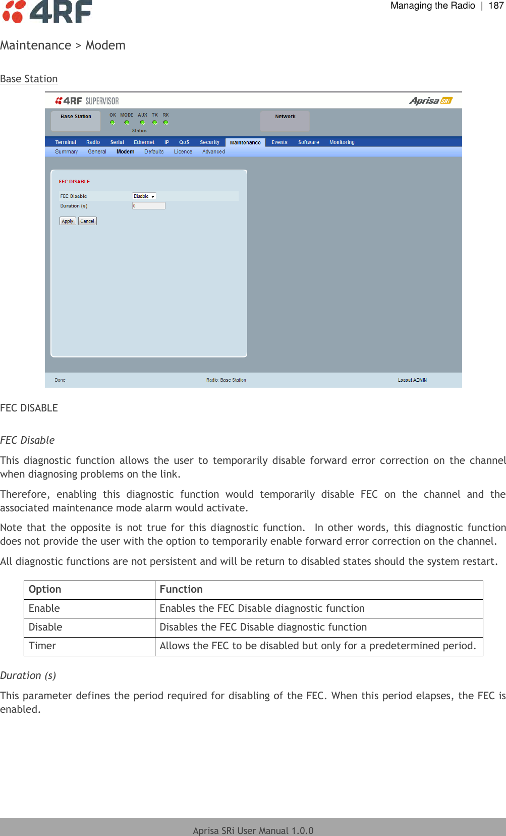
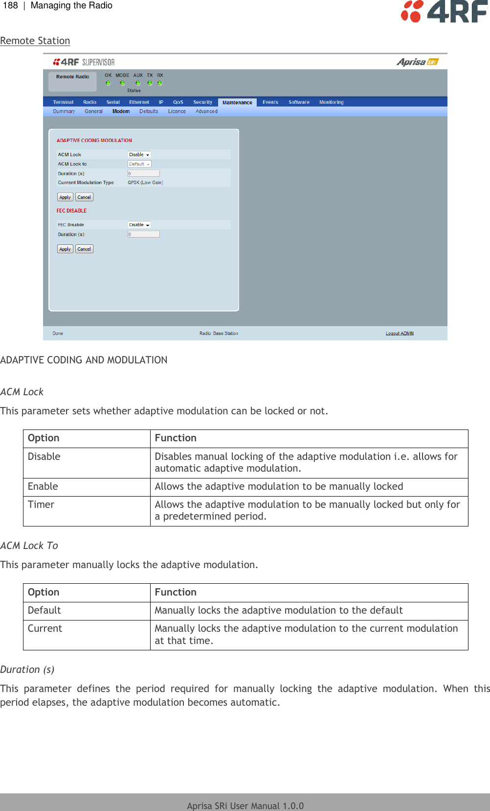
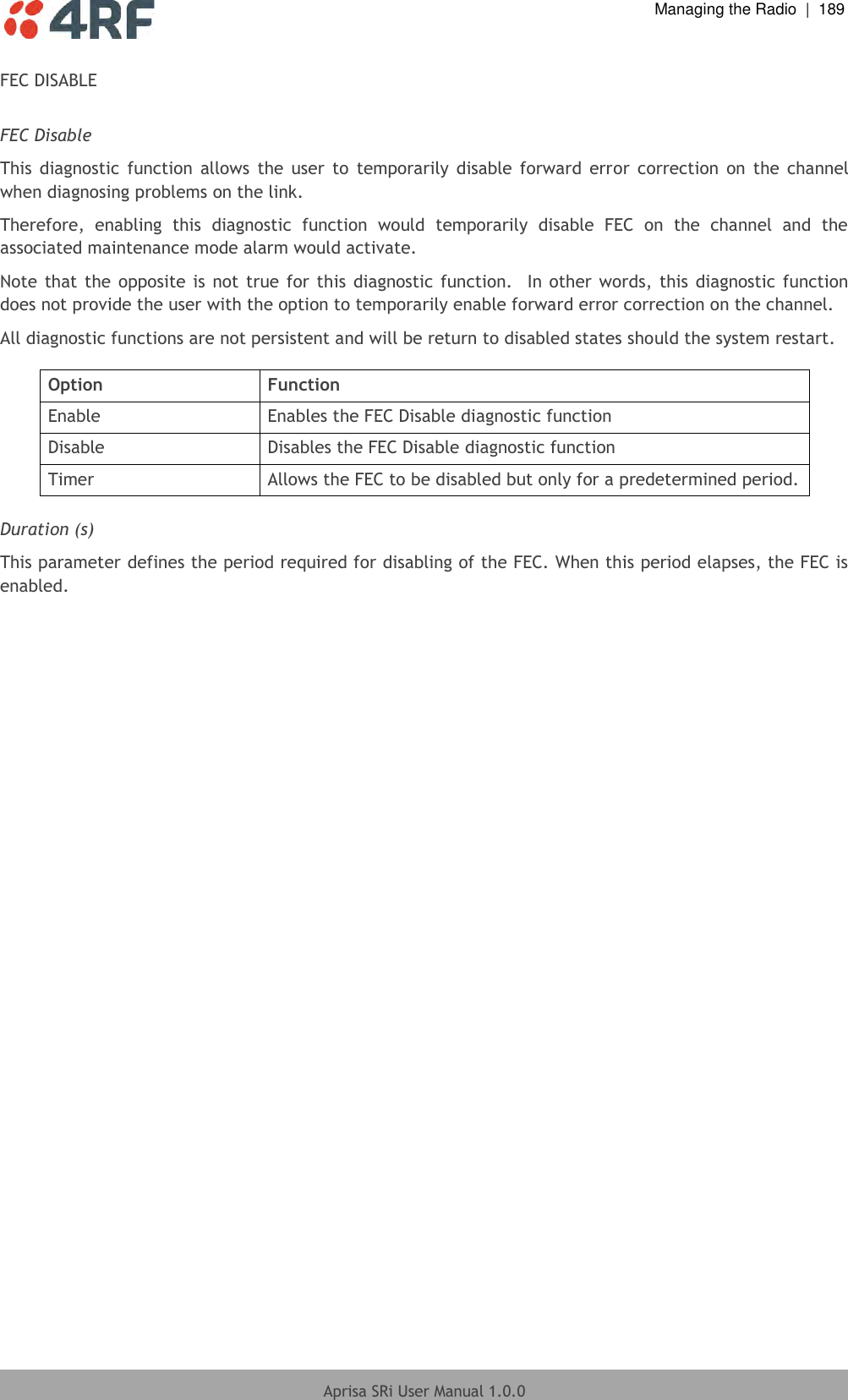
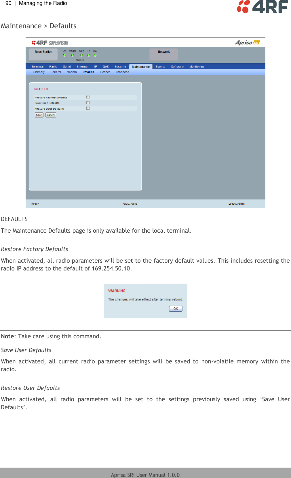
SI902M160 User Manual
User Manual
Navigation menu
Upload a User Manual
Namespaces
Wiki Guide
HTML
PDF
Info
Views
User Manual
Discussion / Help
Navigation


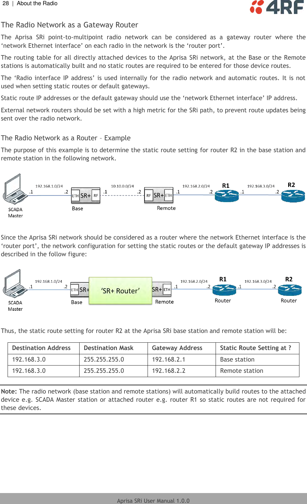
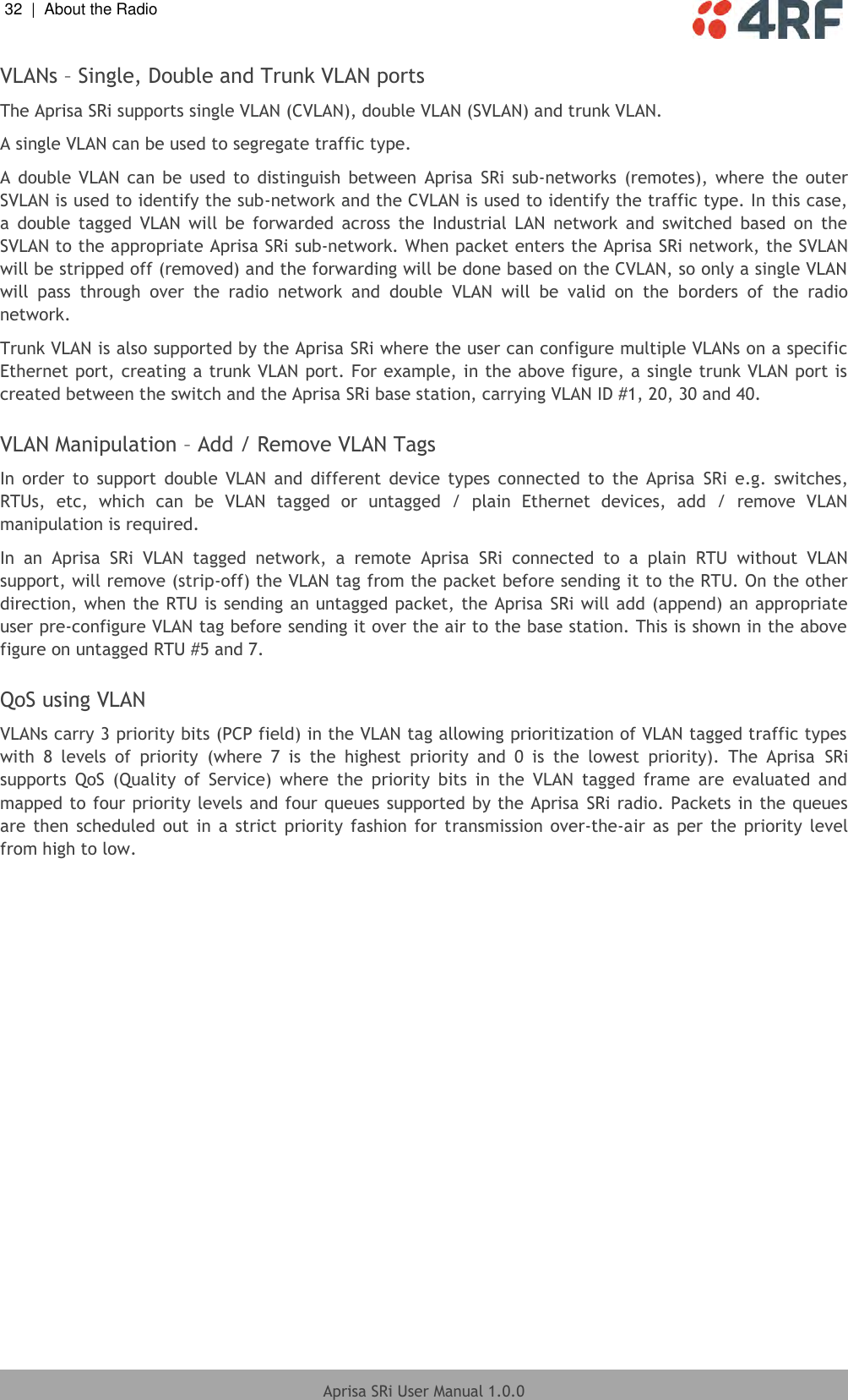
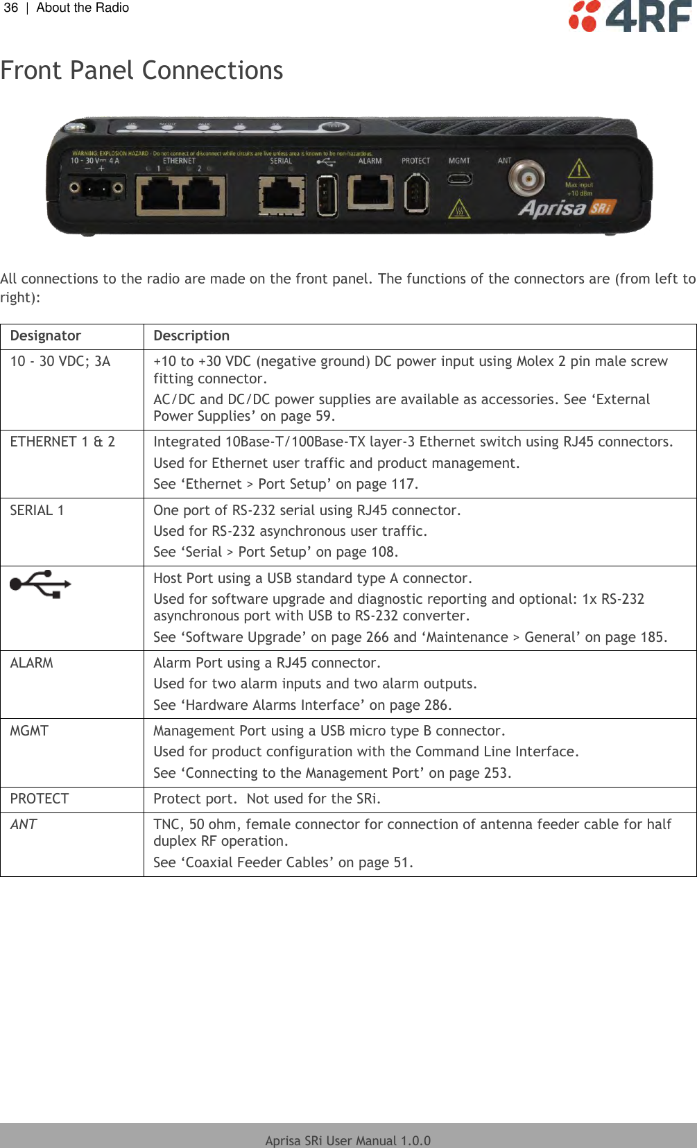

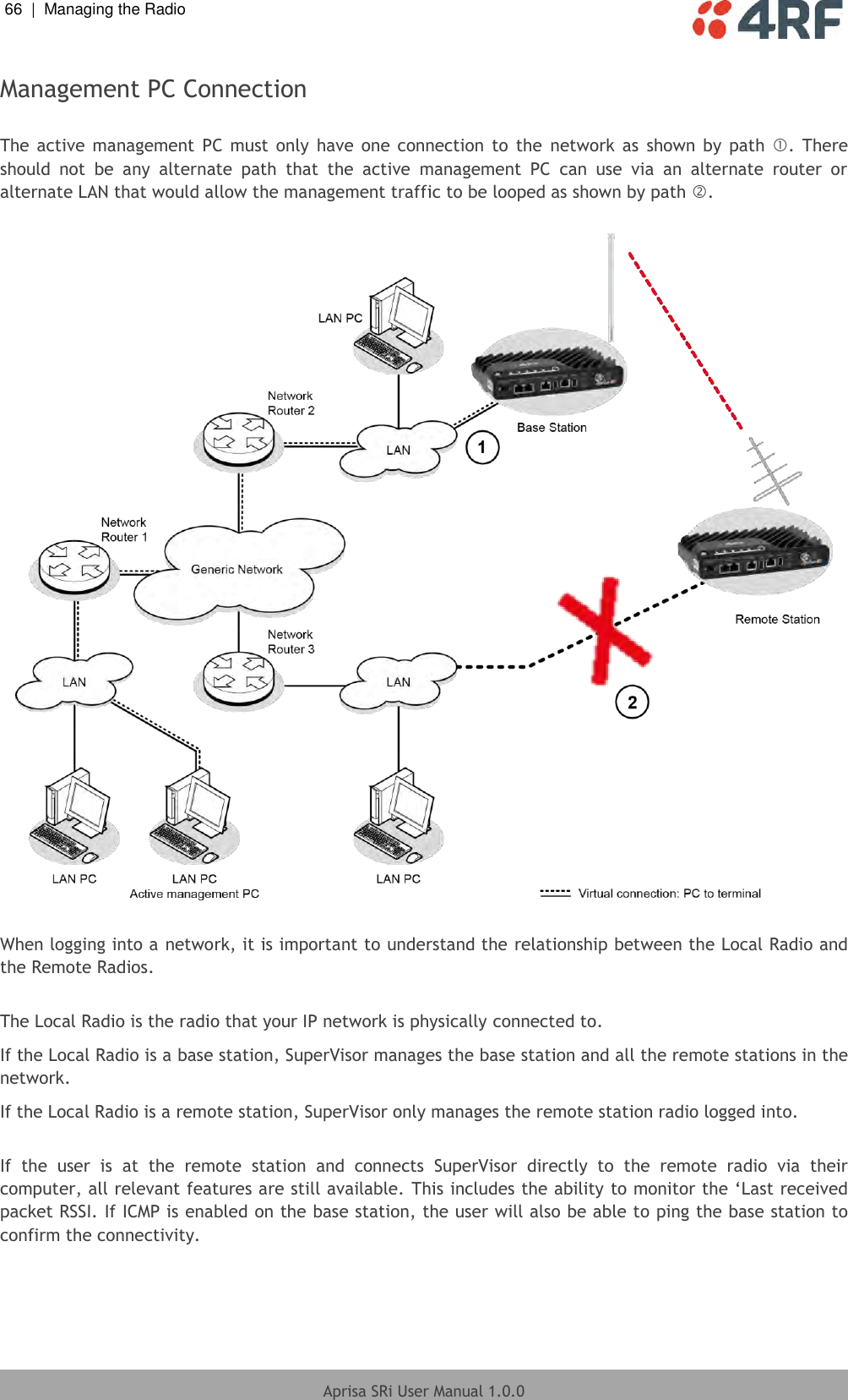
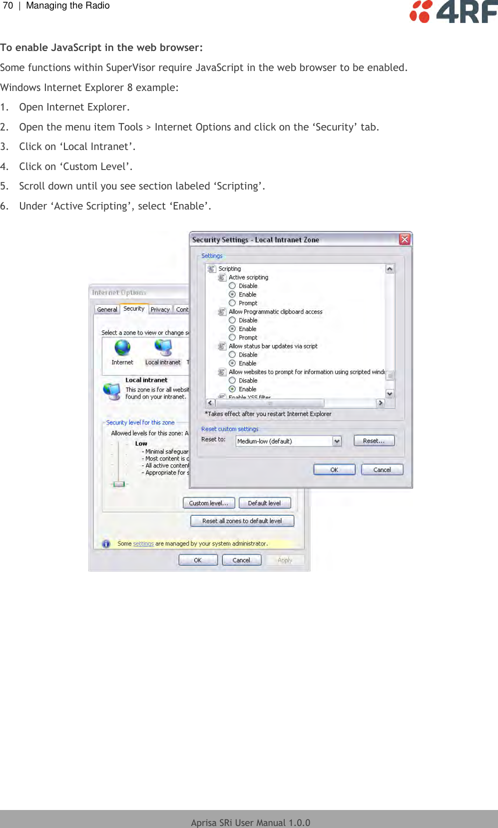
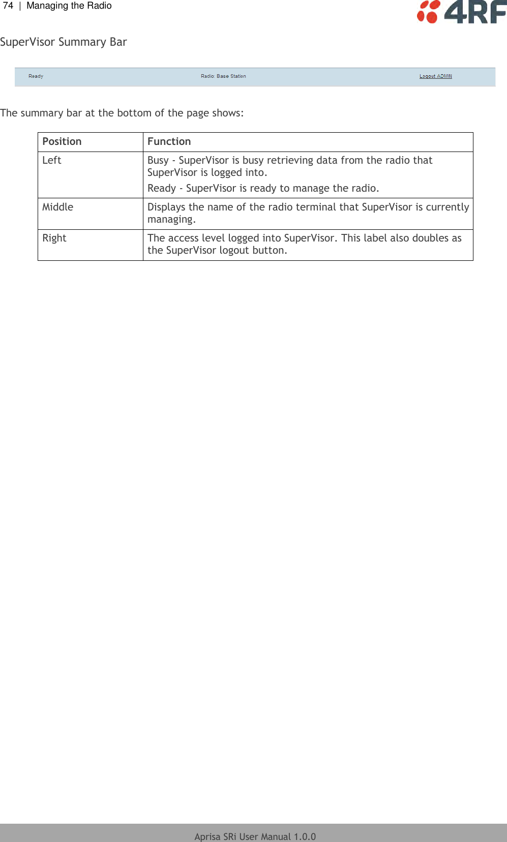
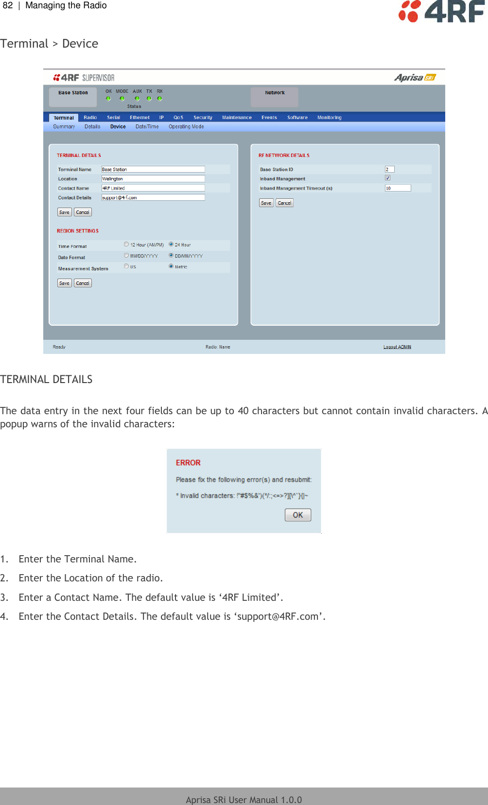
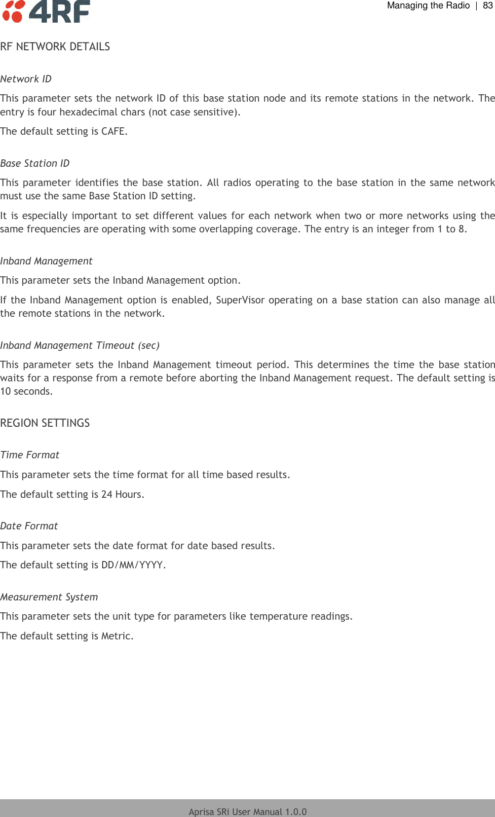
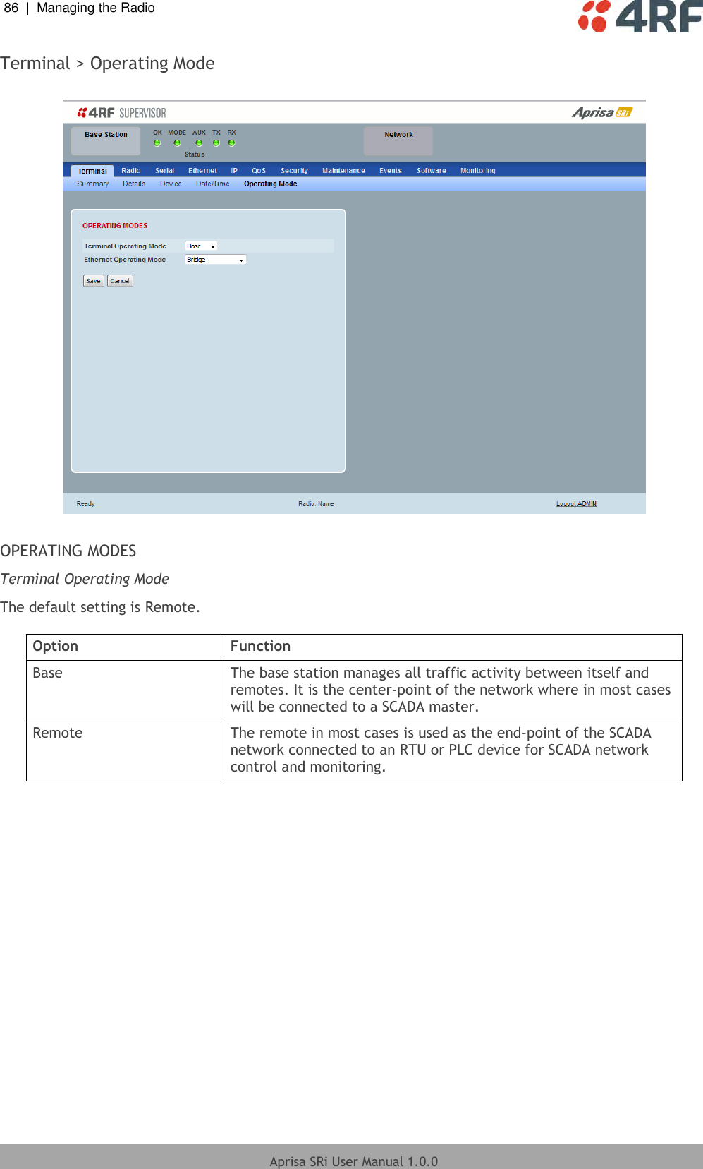
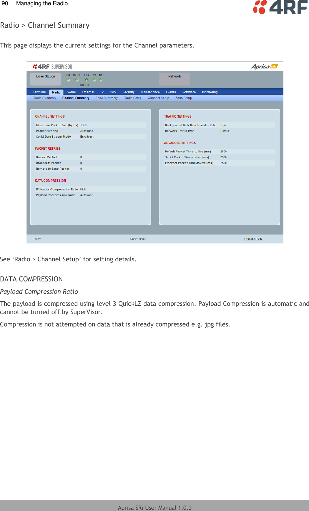
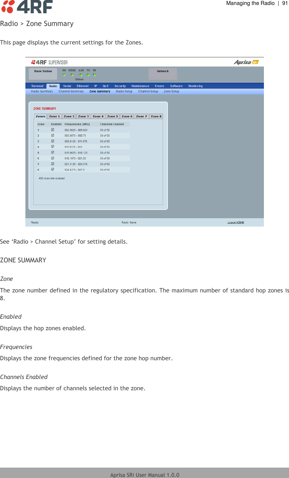
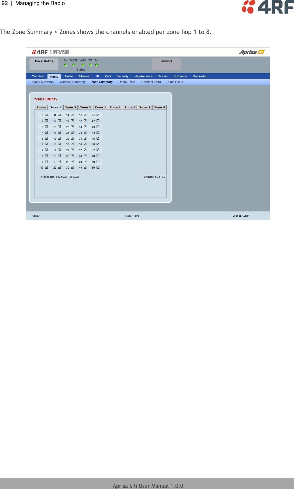
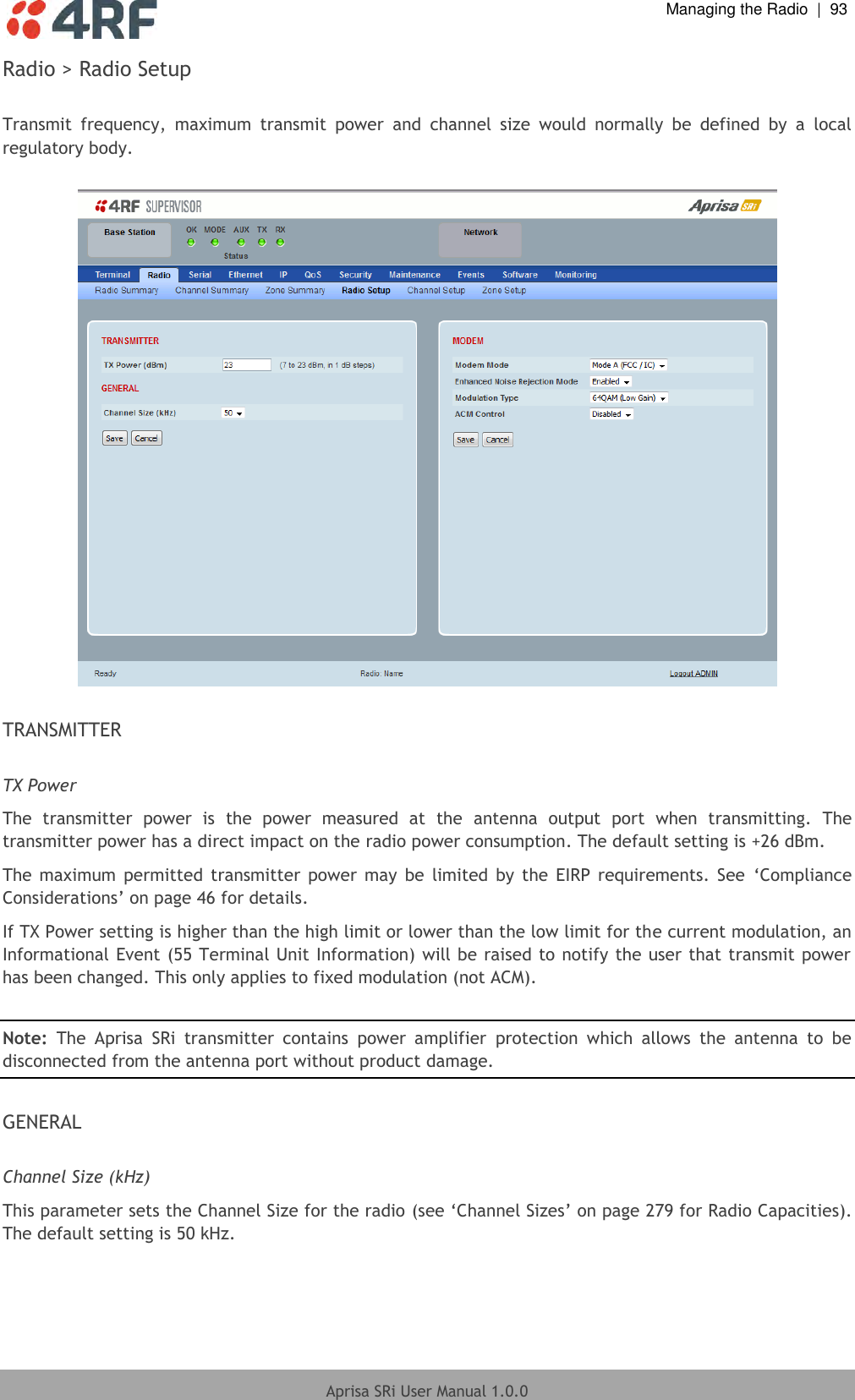
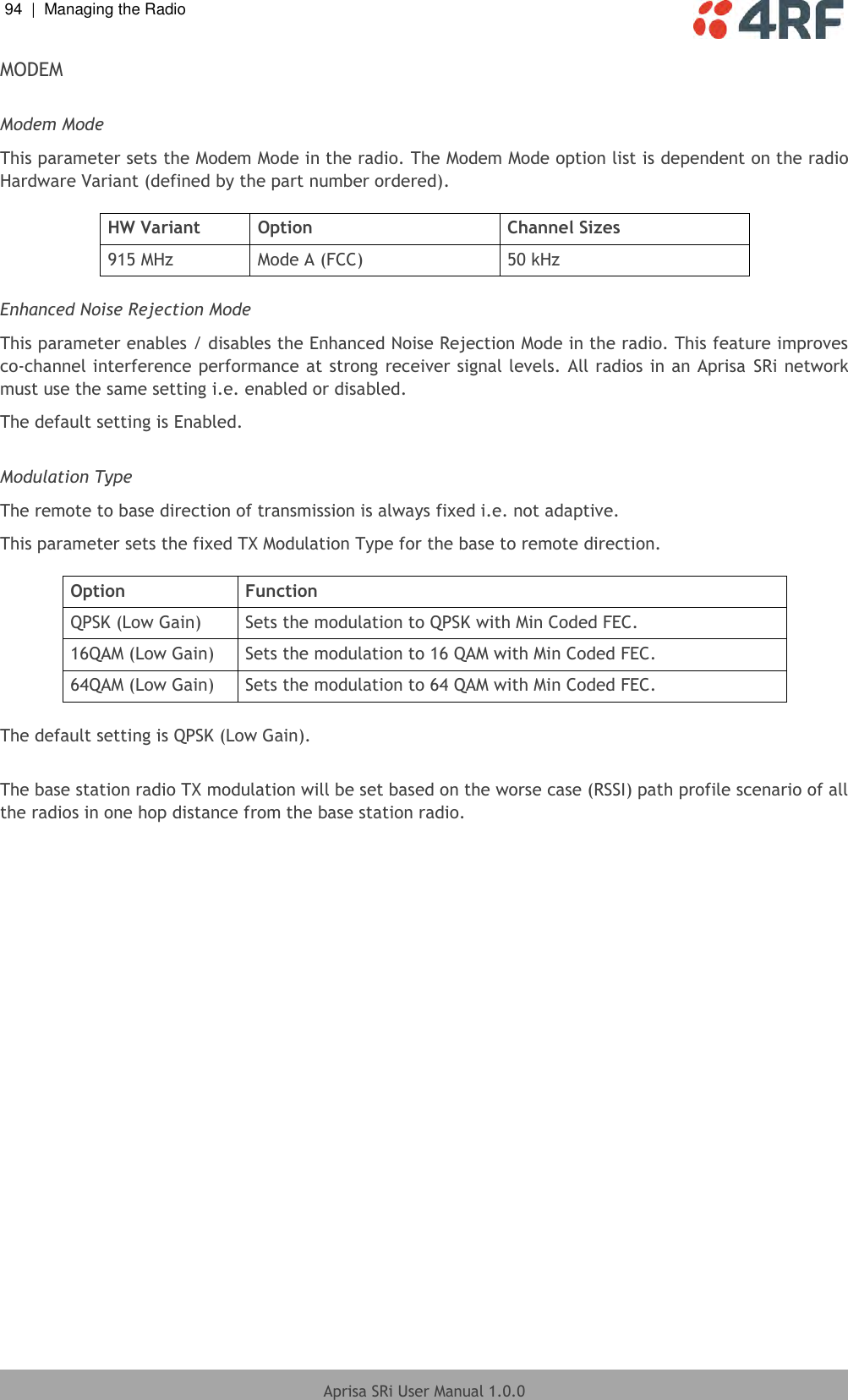
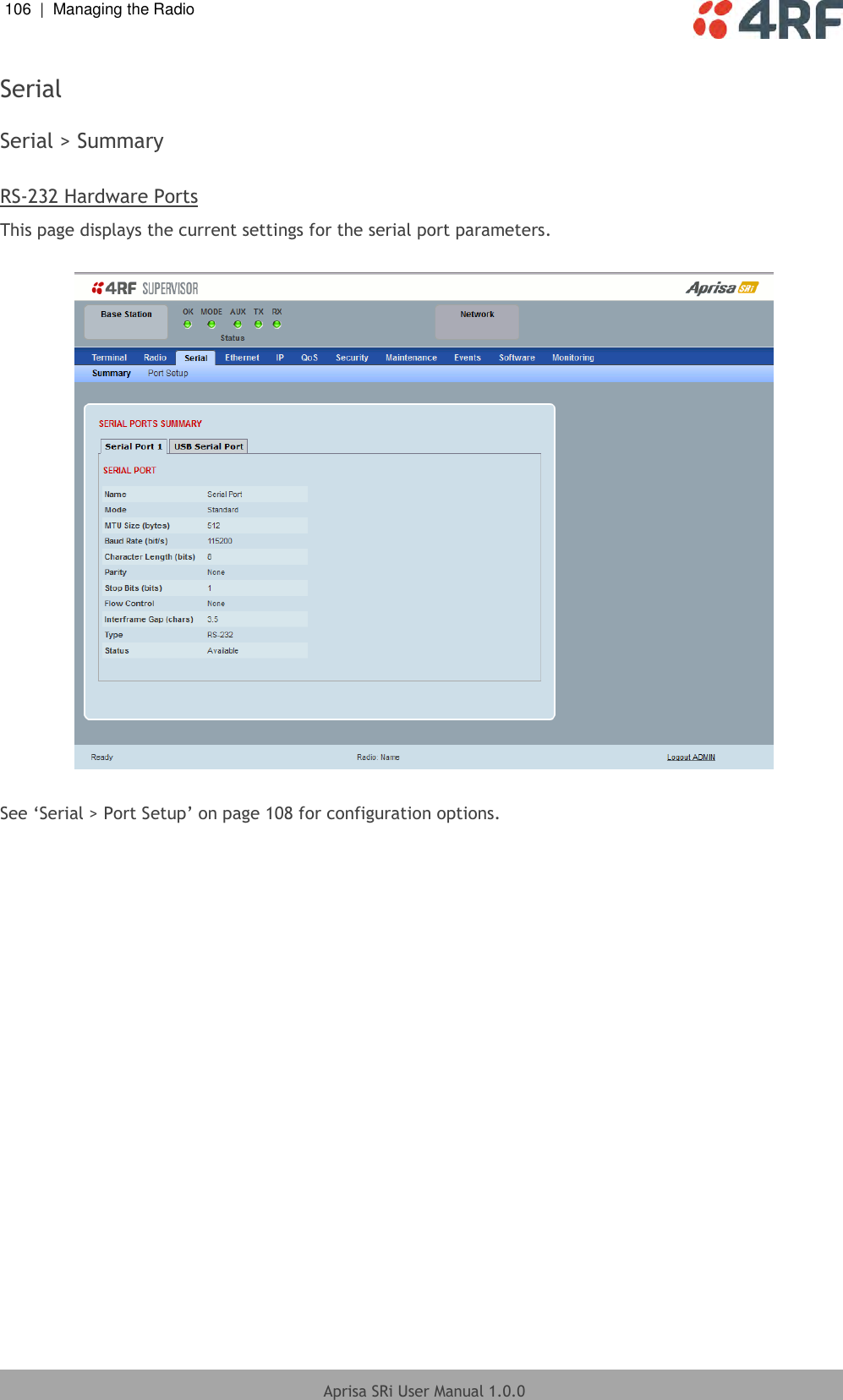
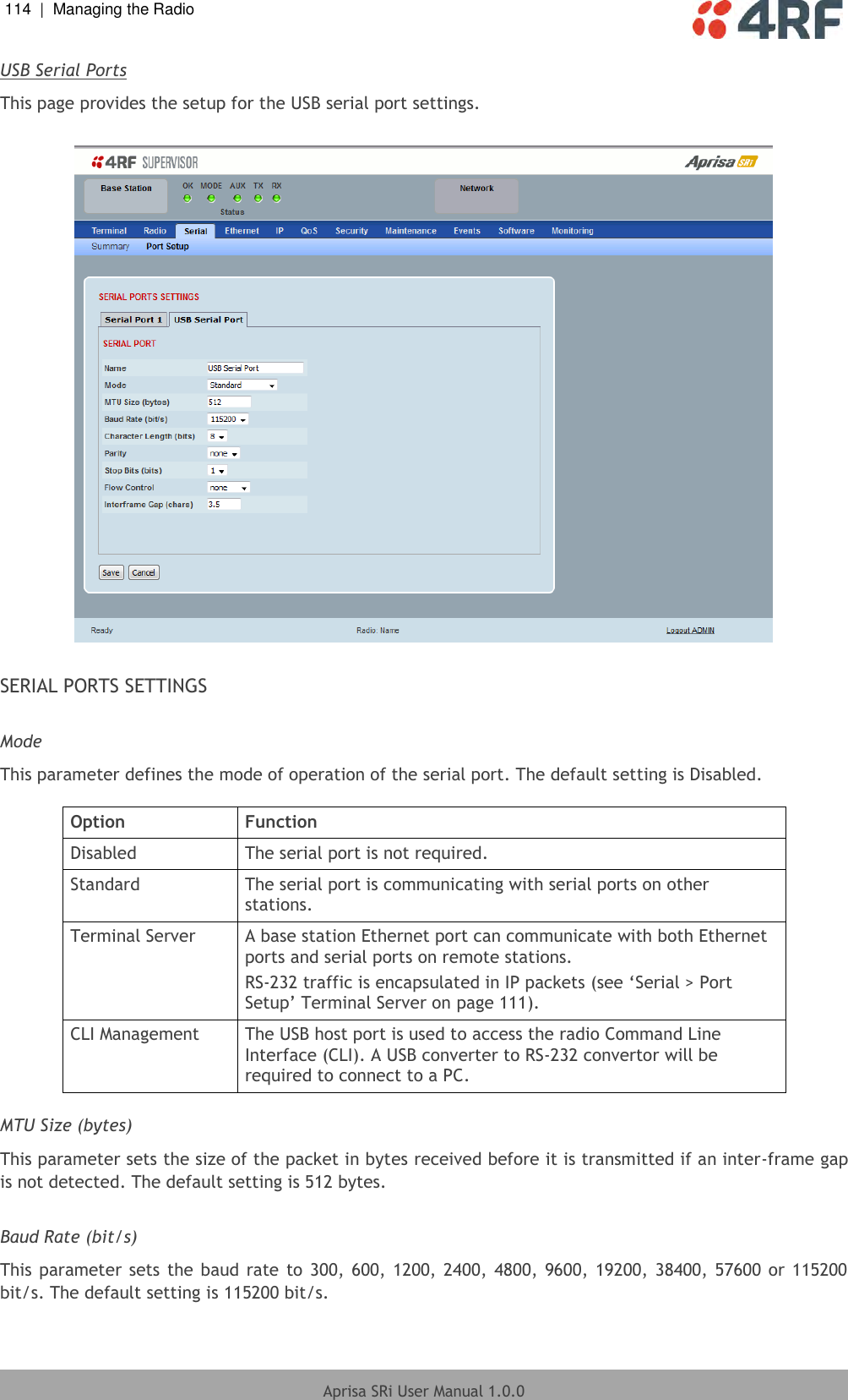


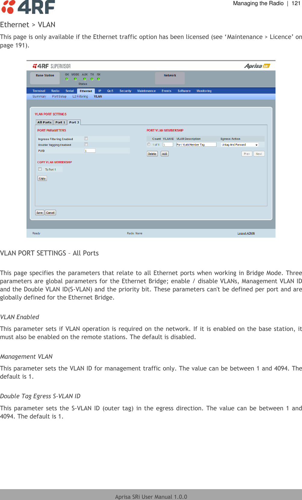

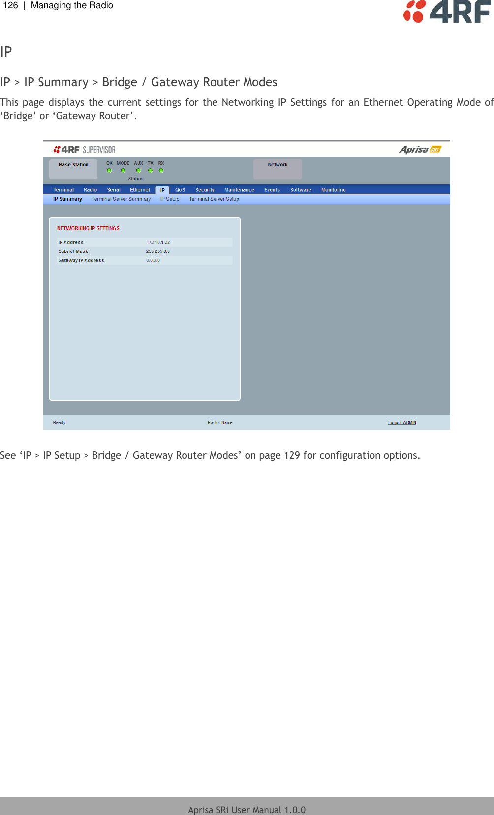
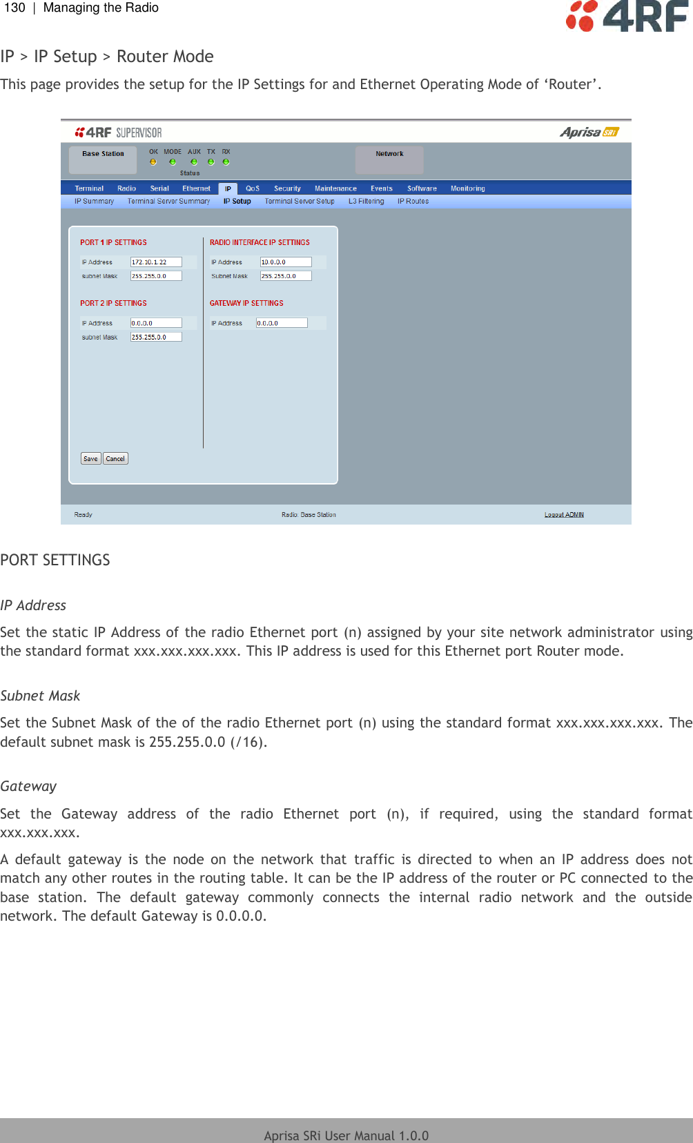

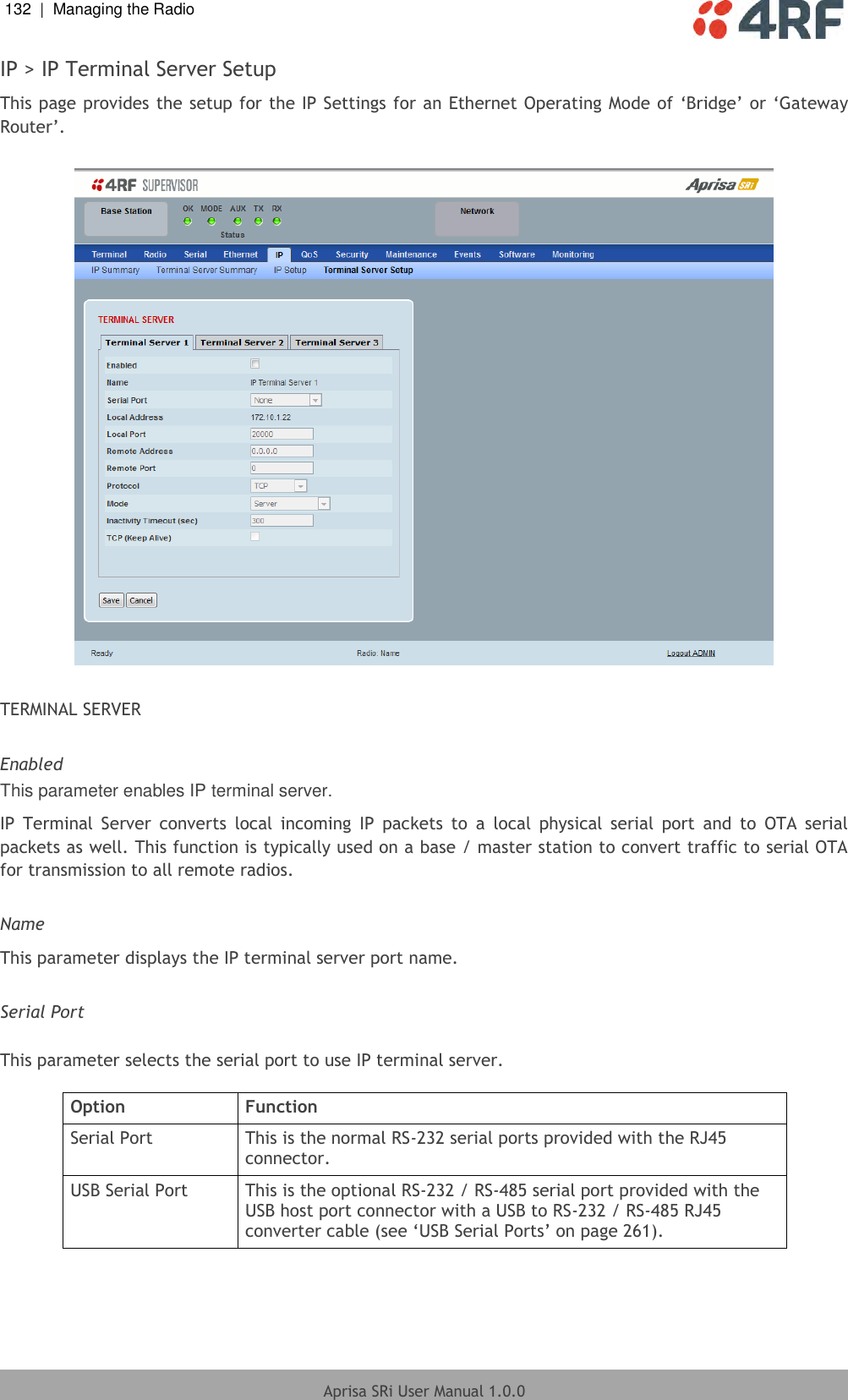
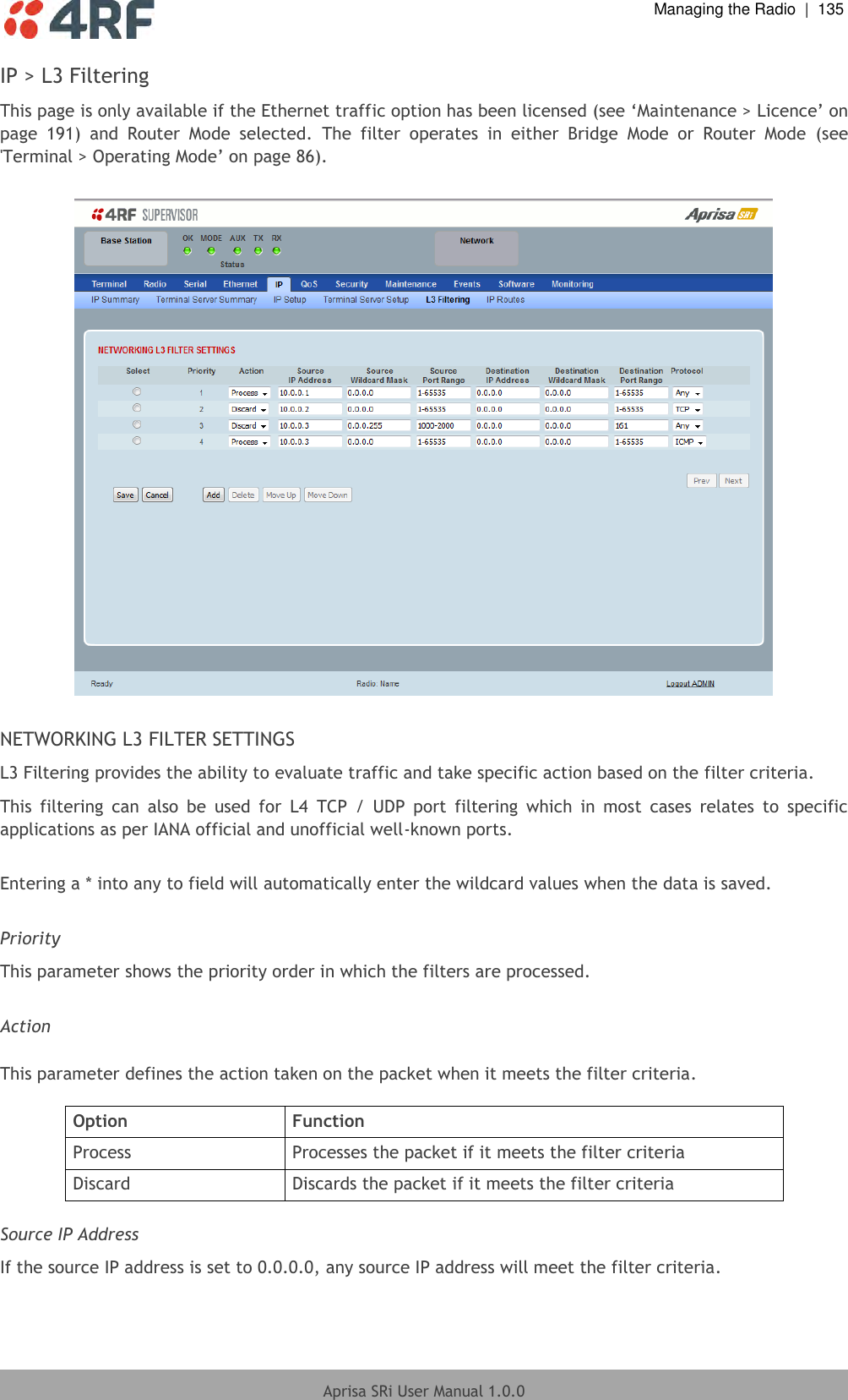
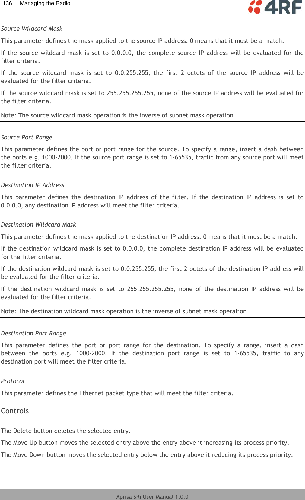

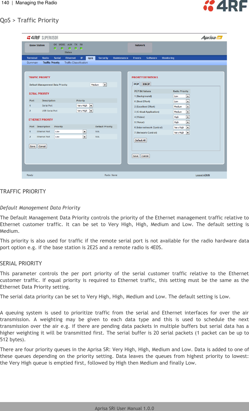

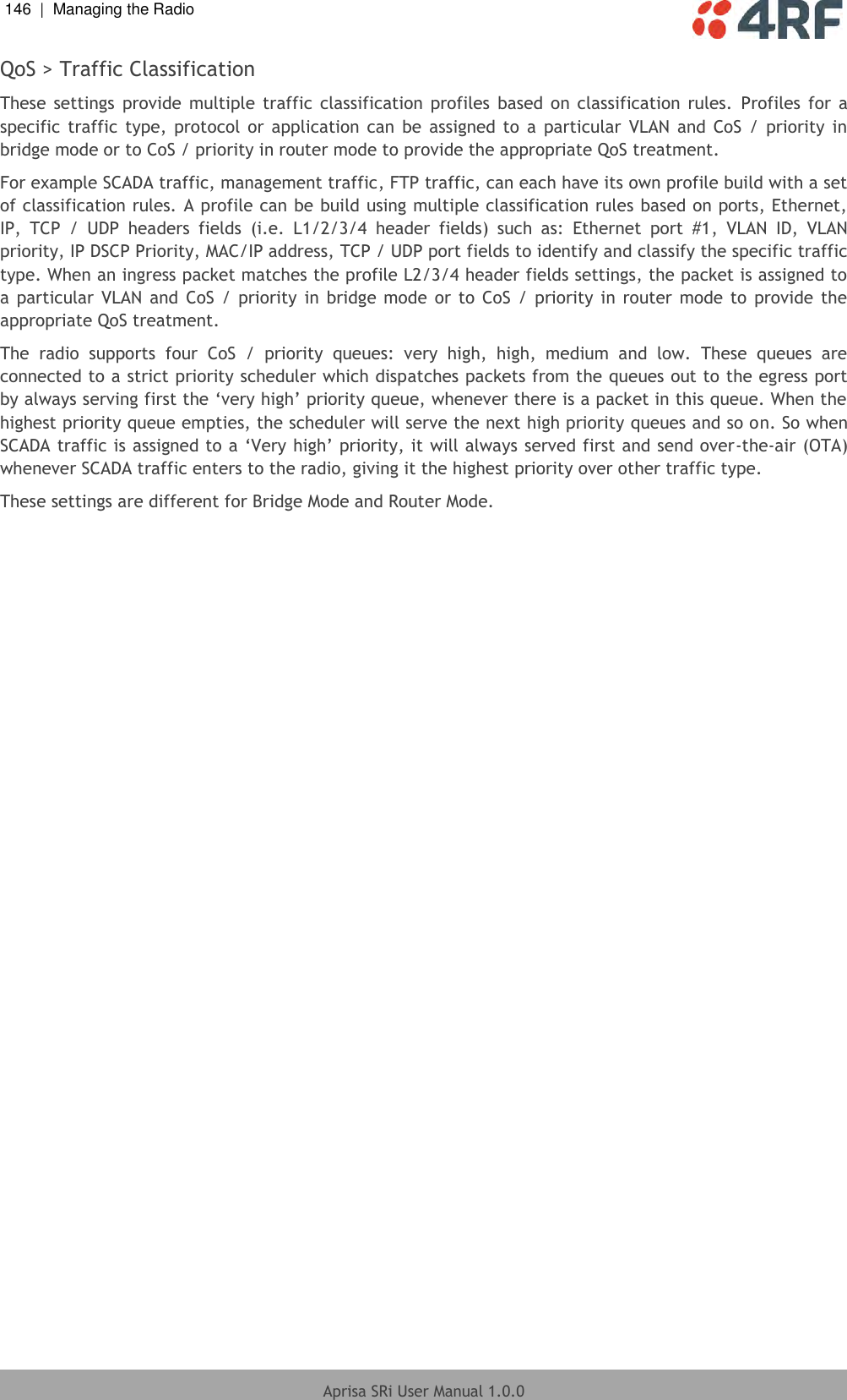

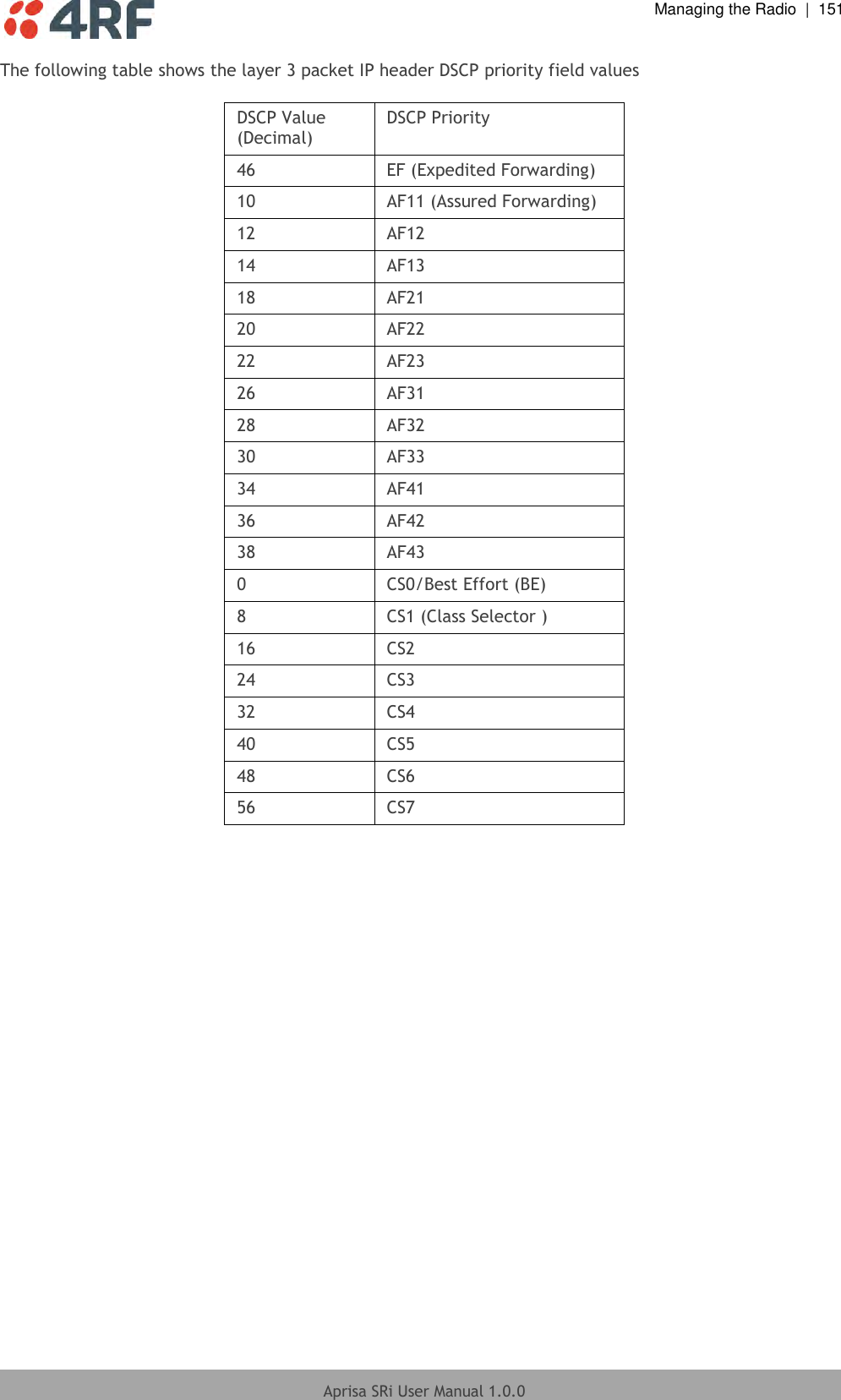
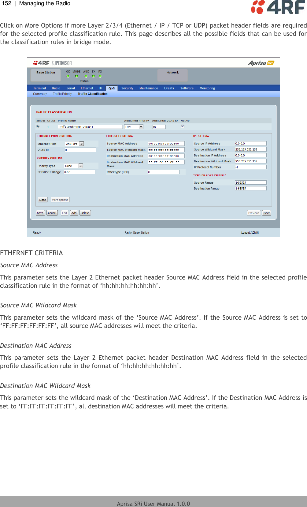
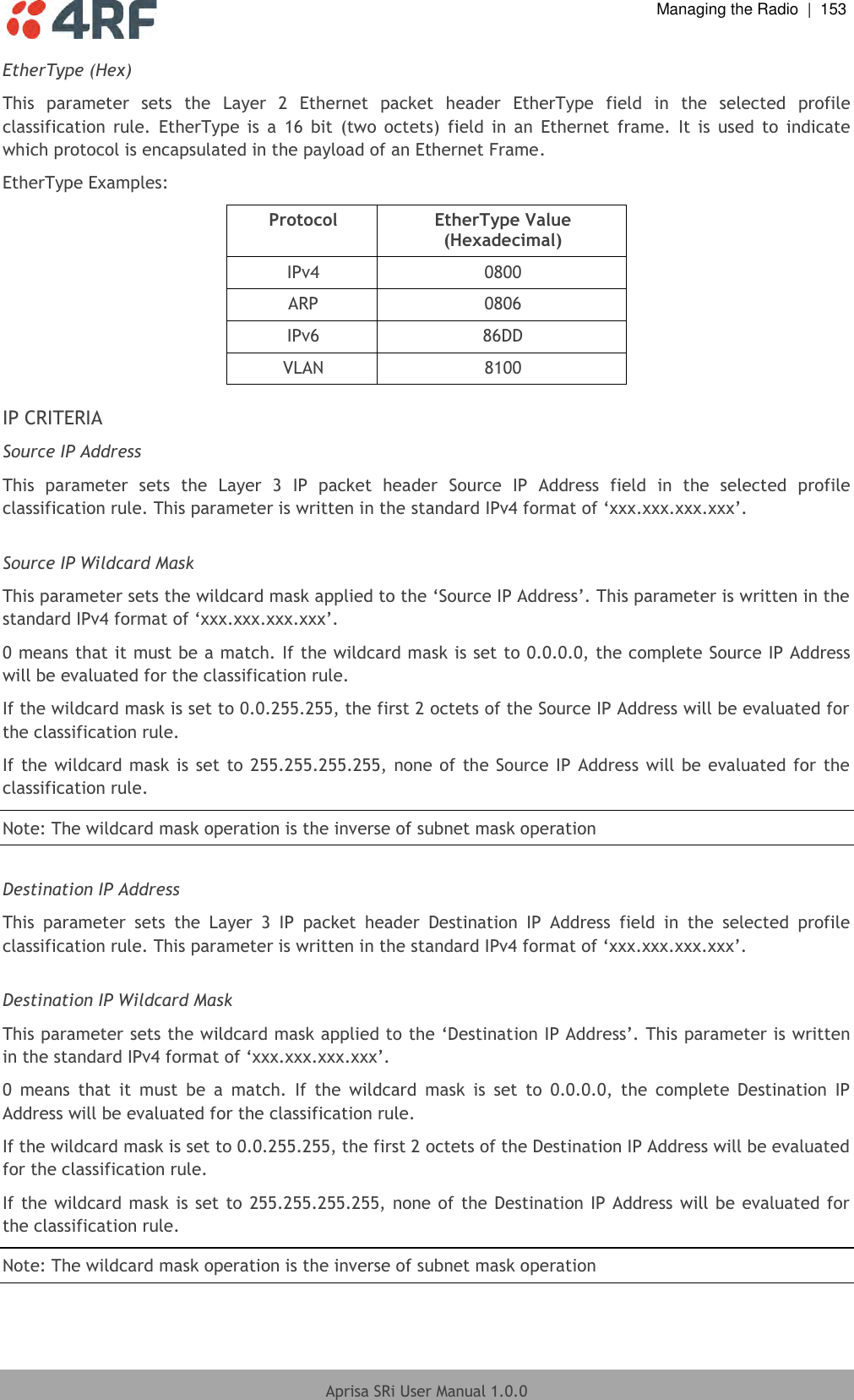
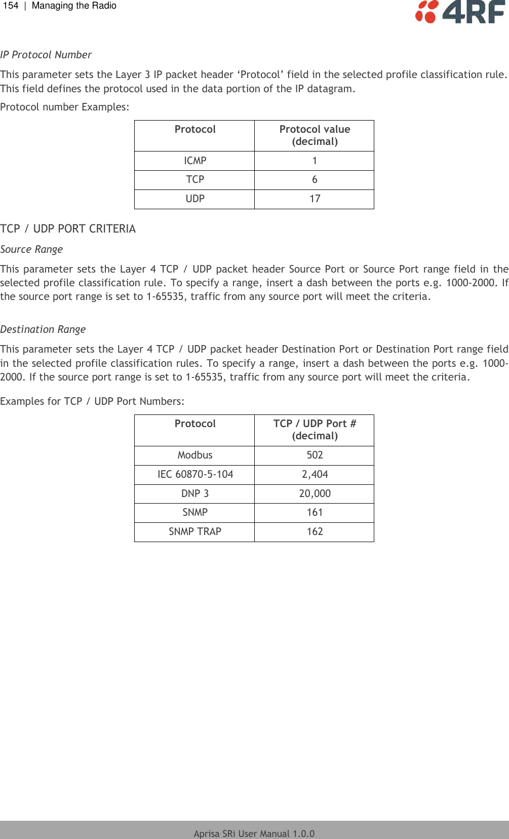
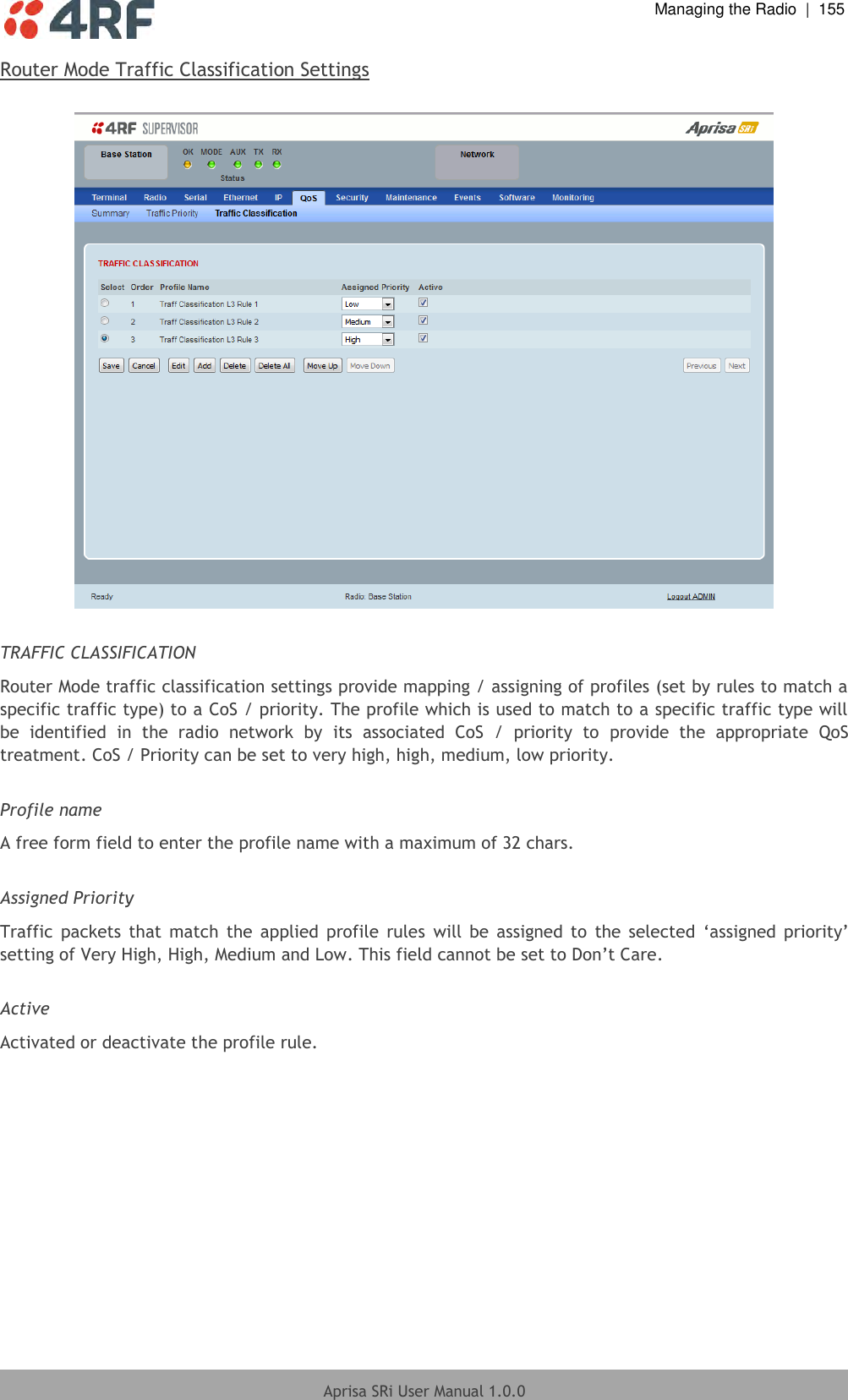
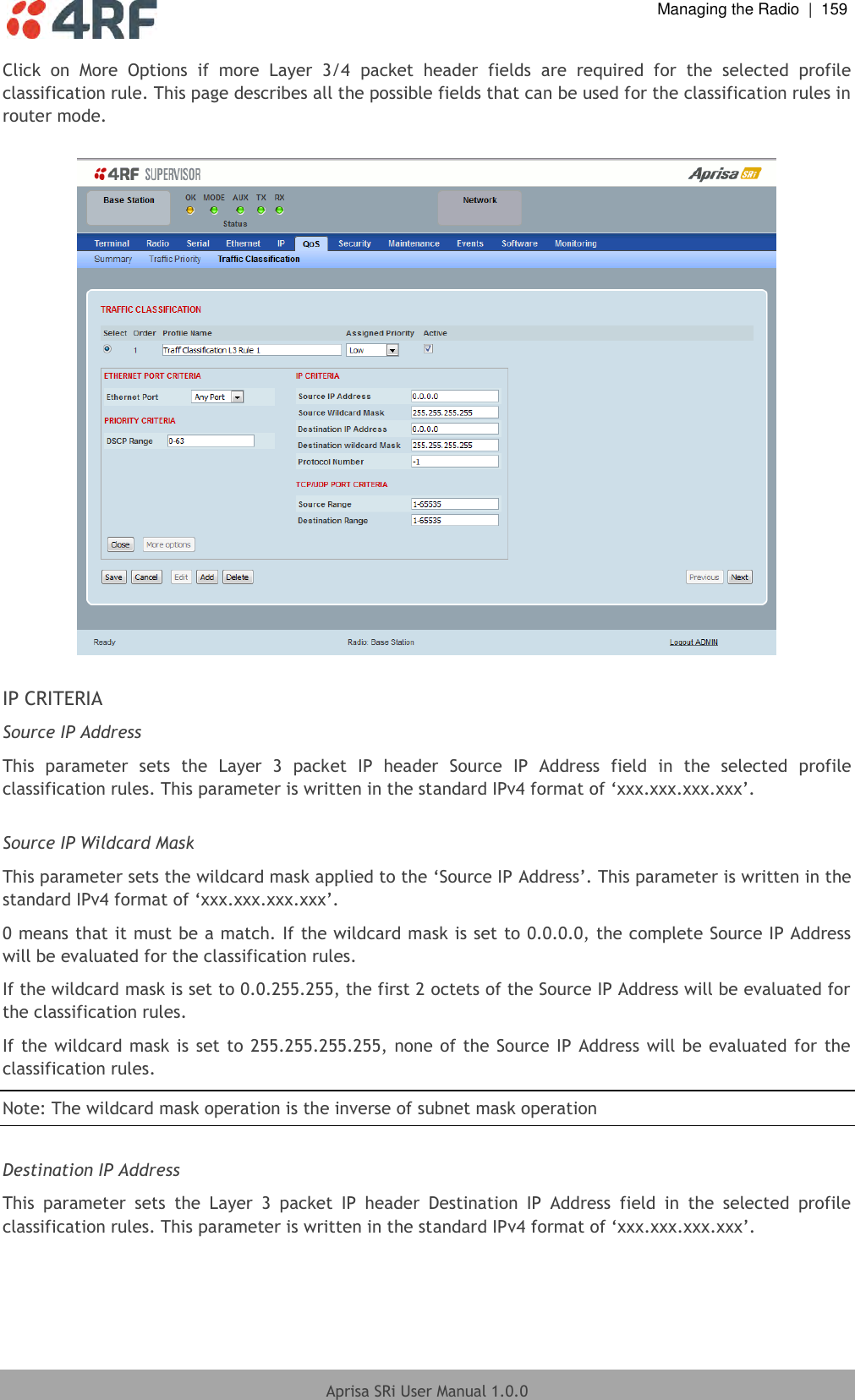
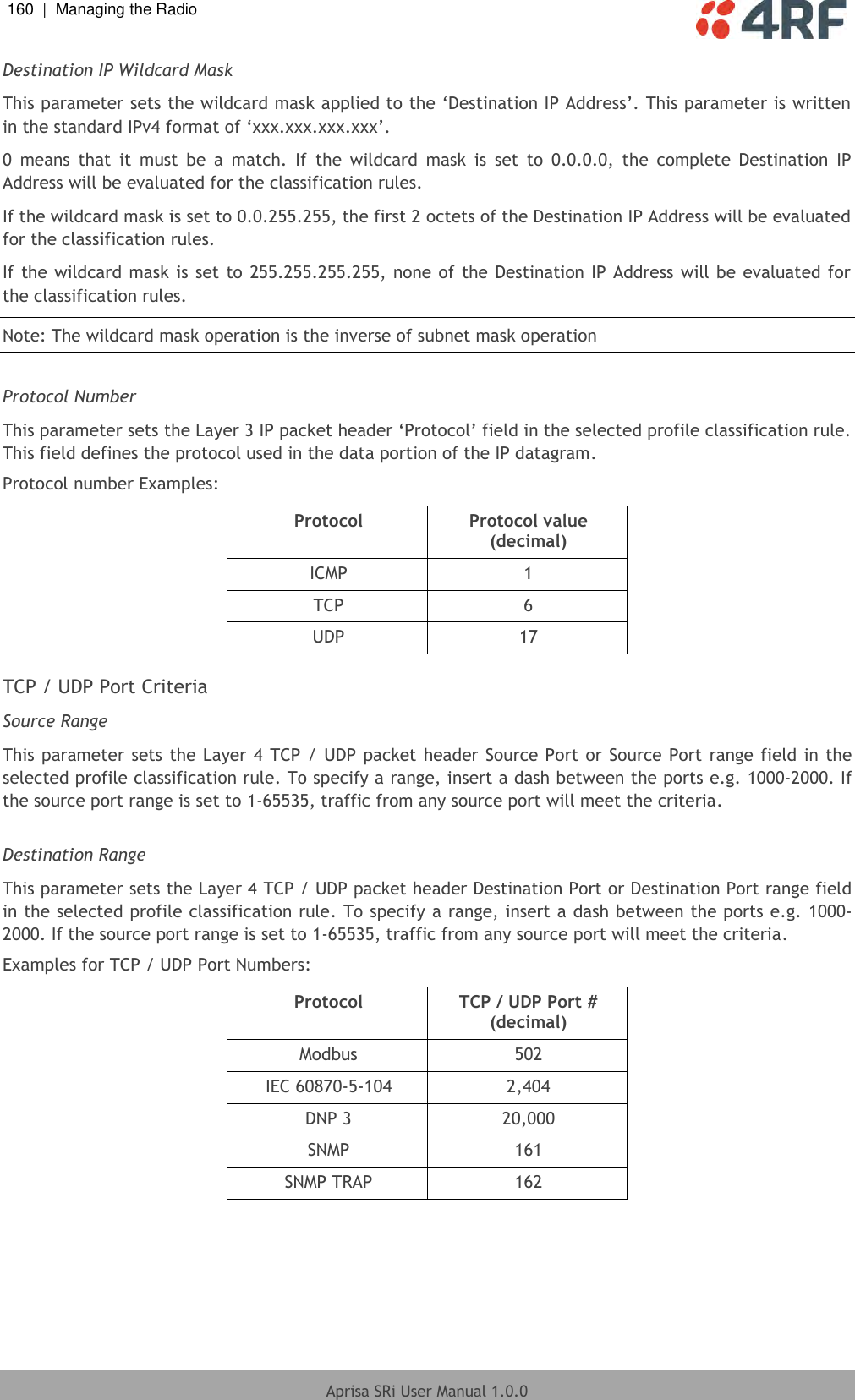
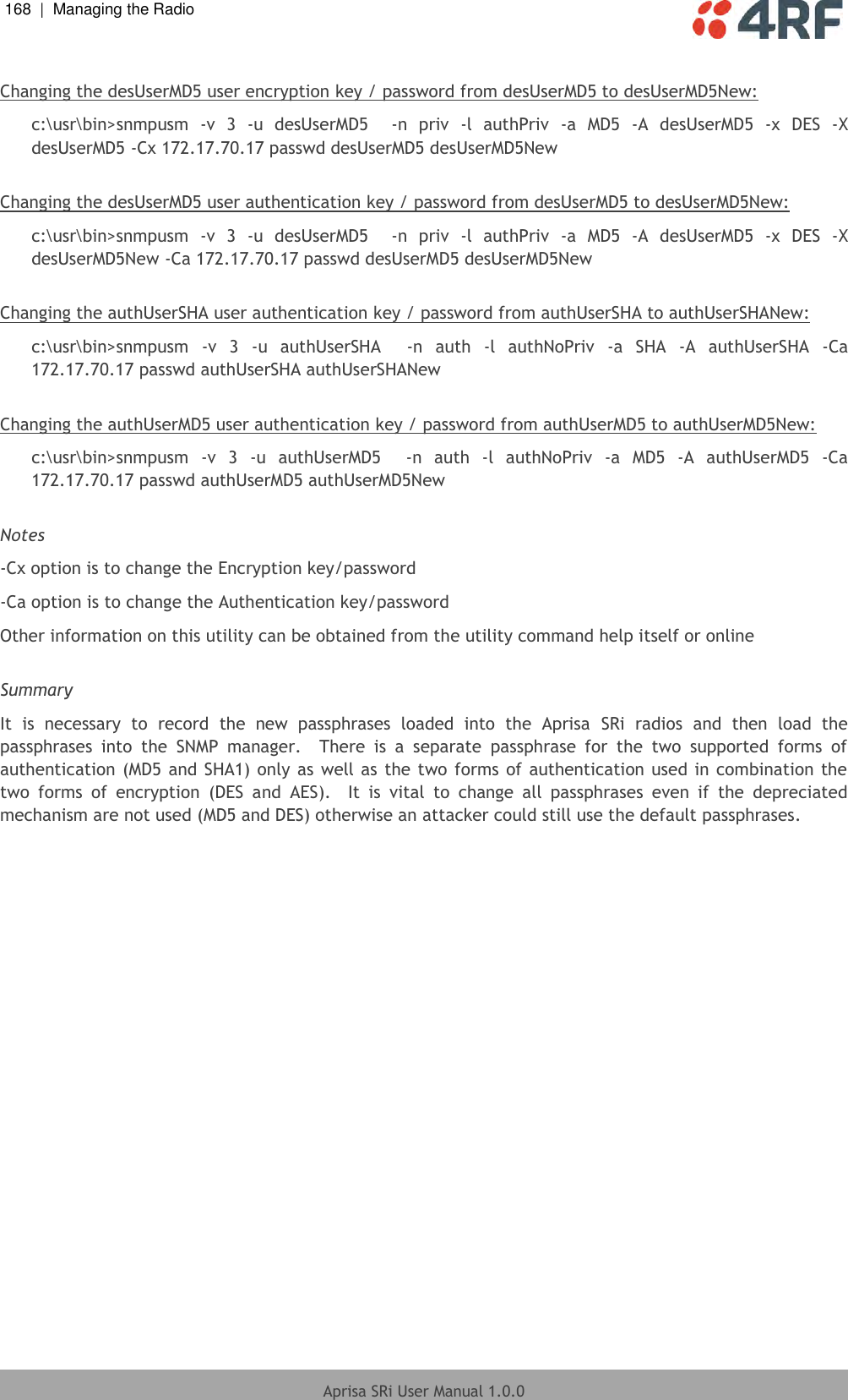
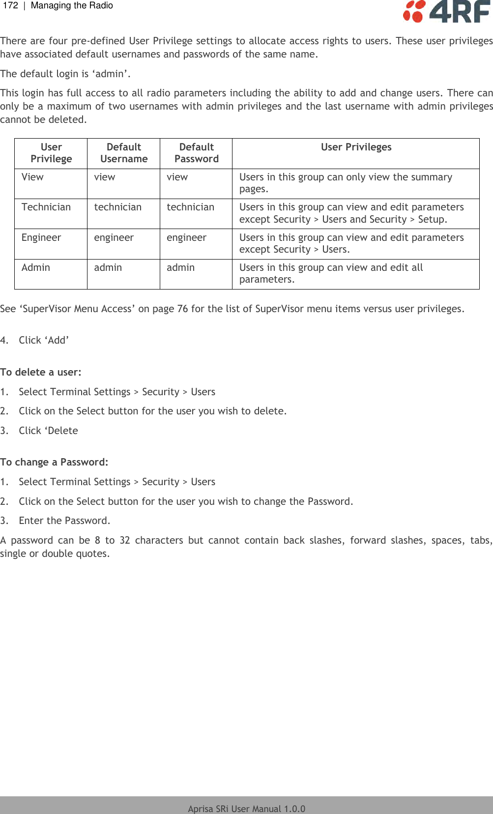
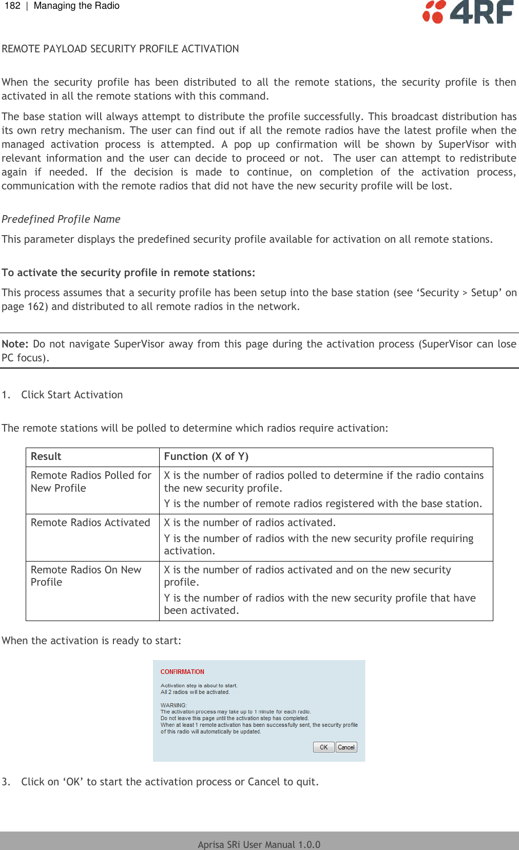
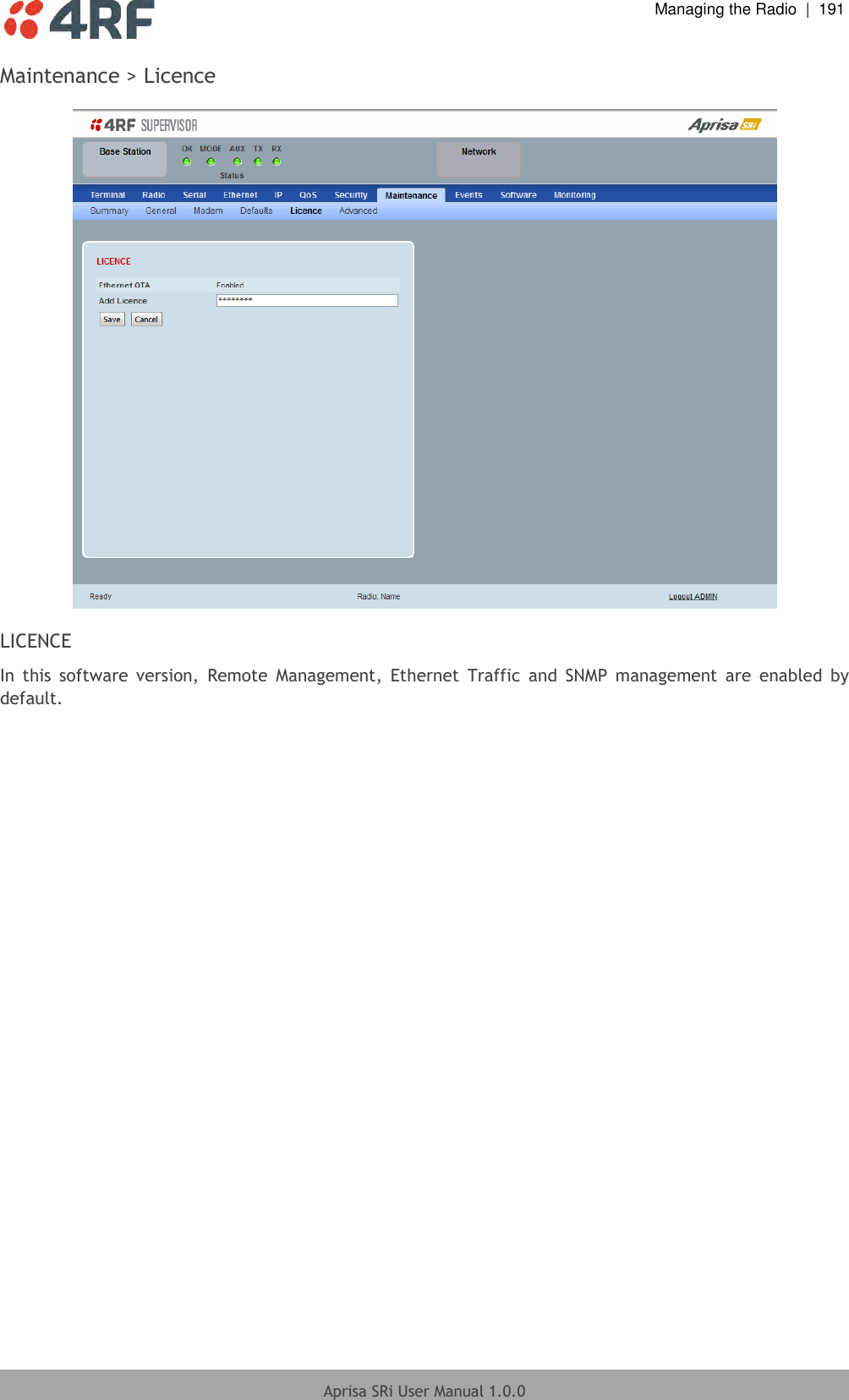
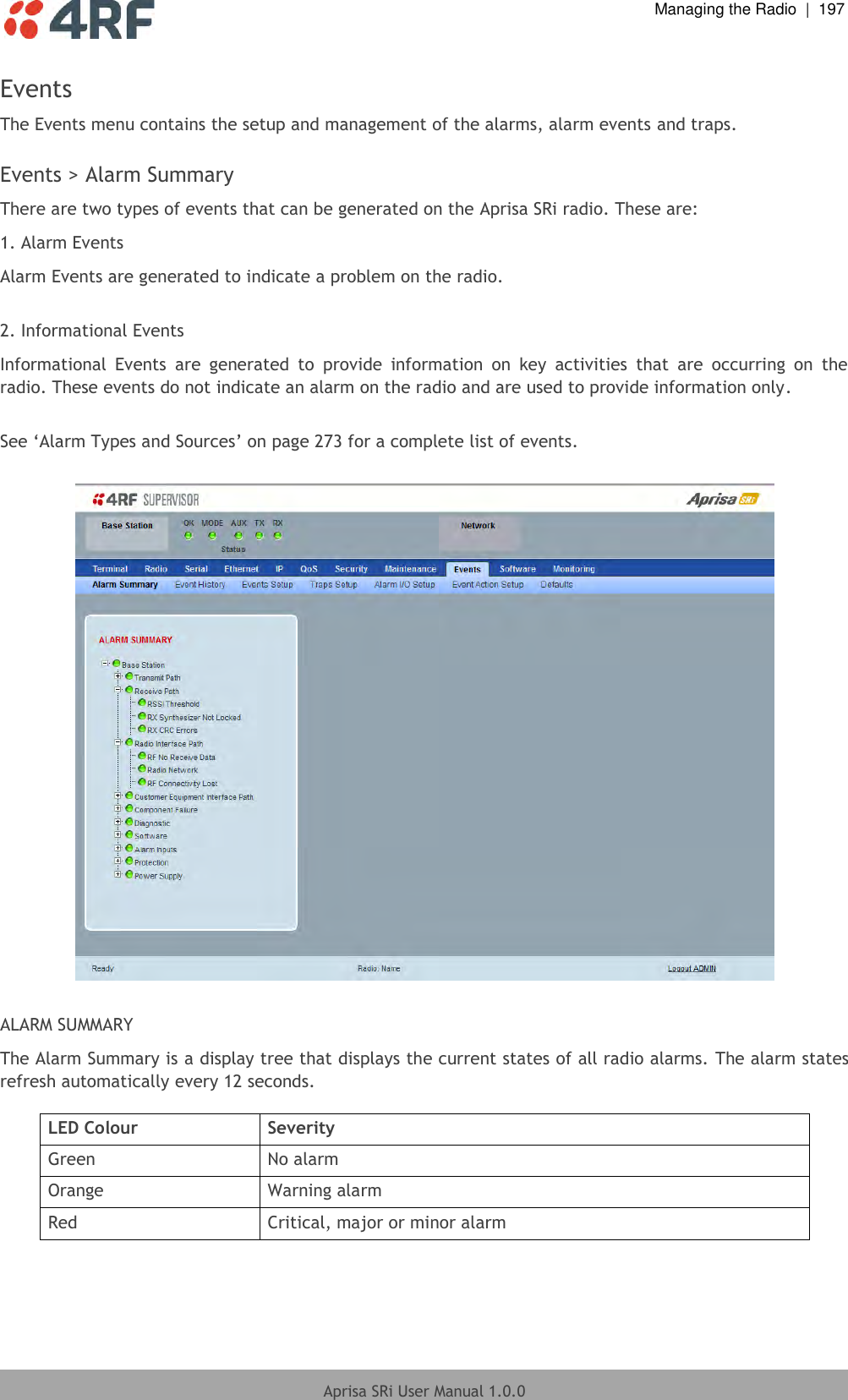
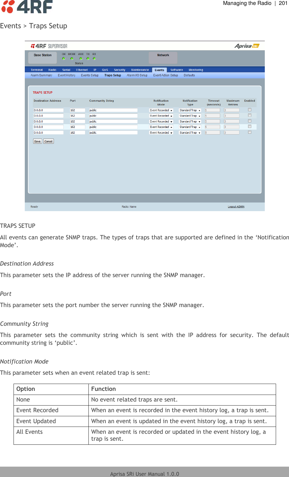
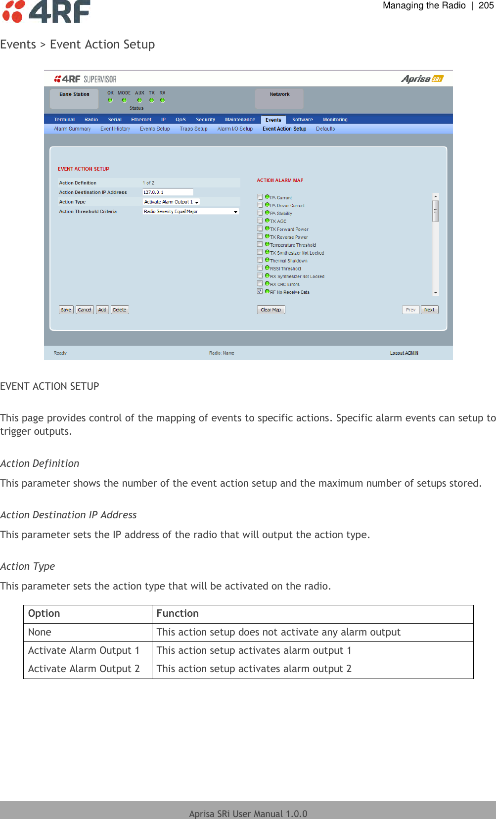
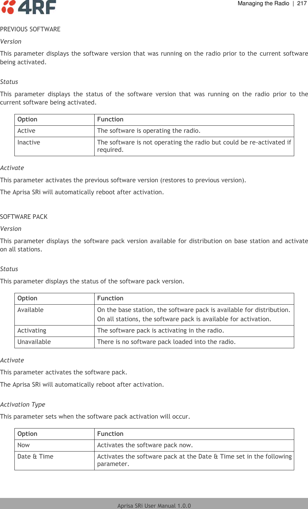
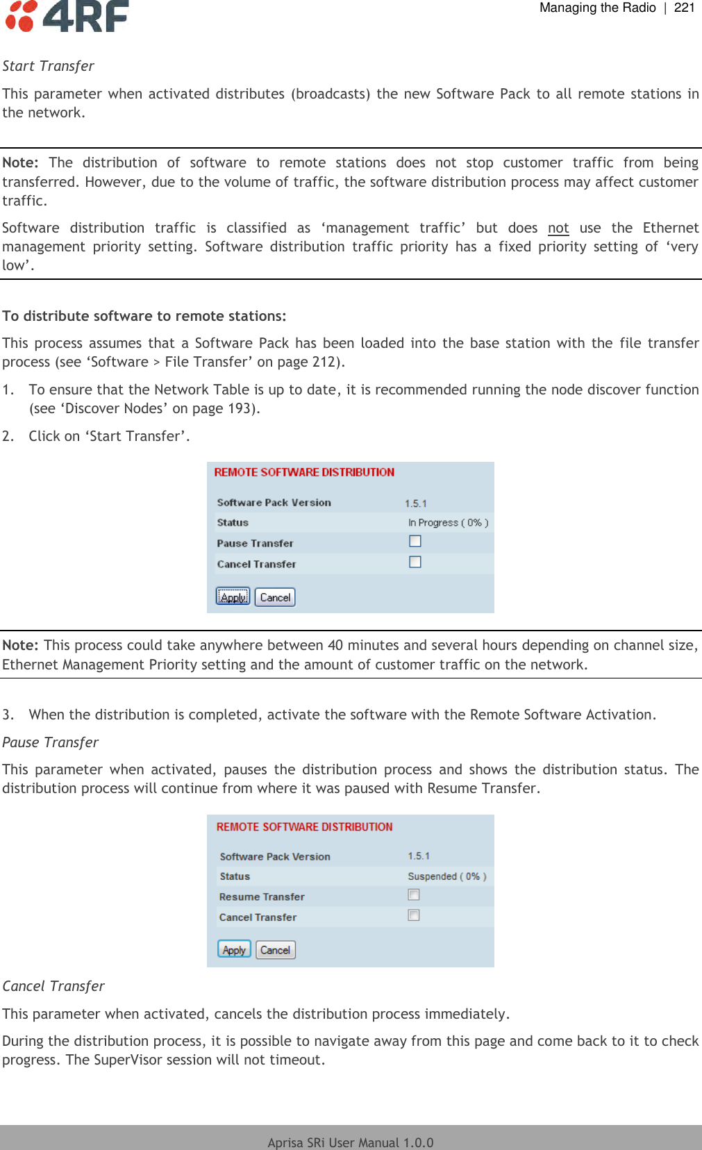
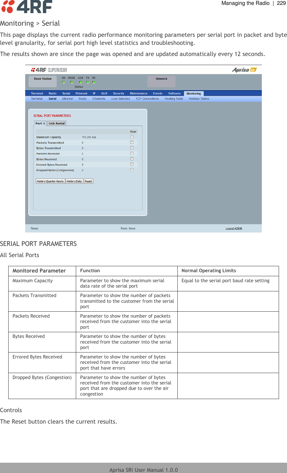
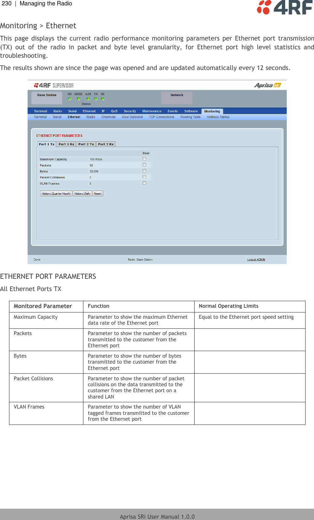
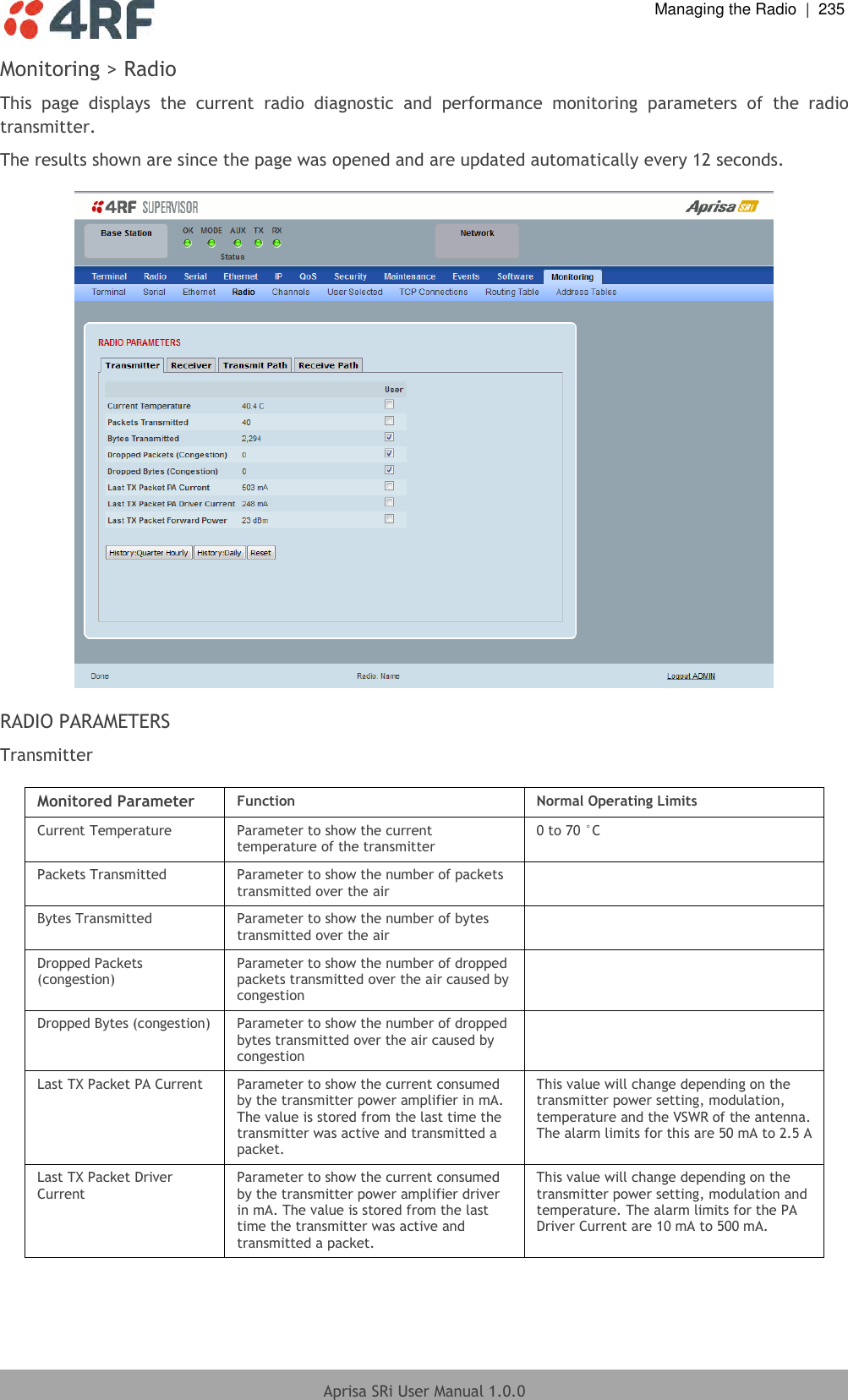
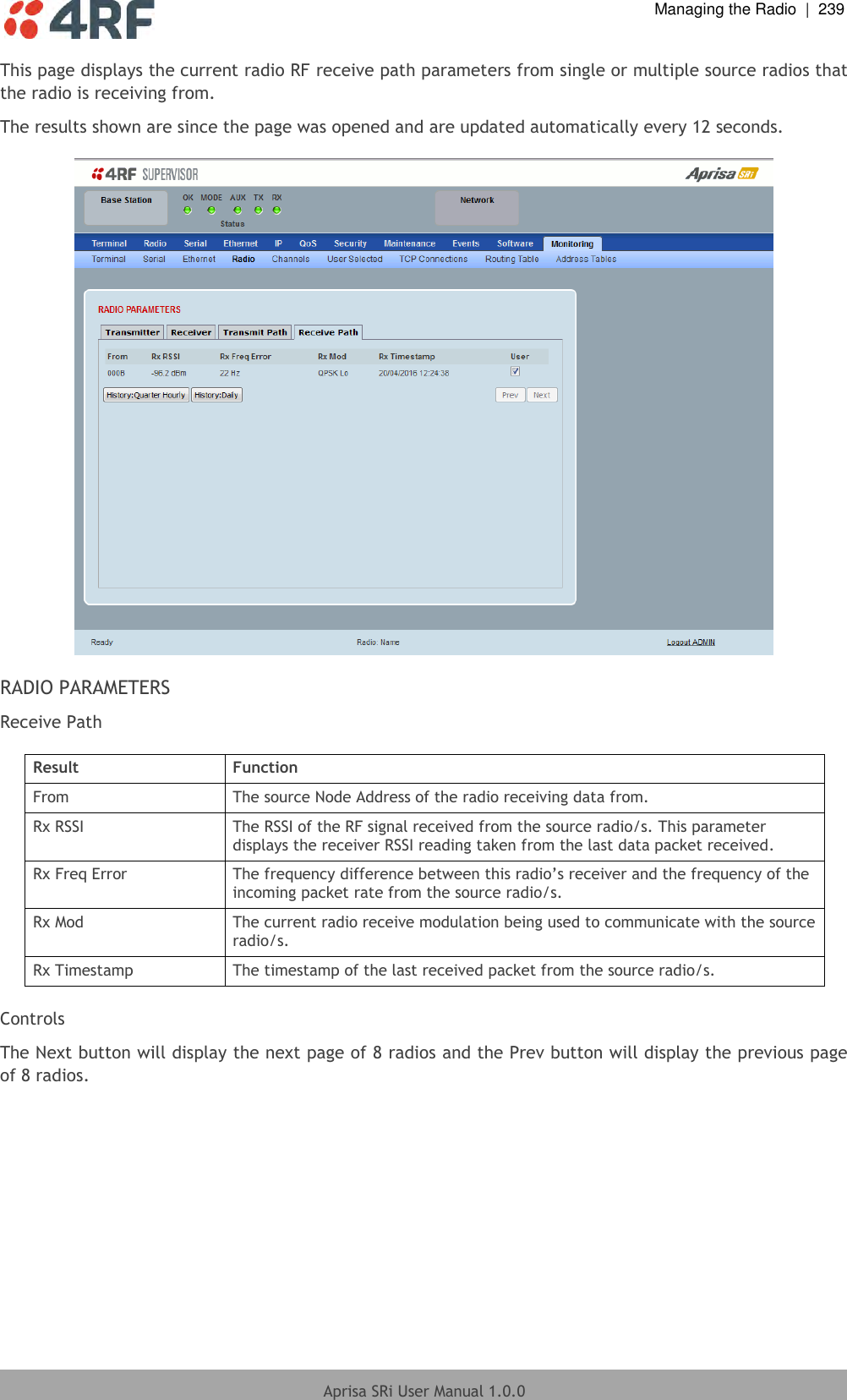
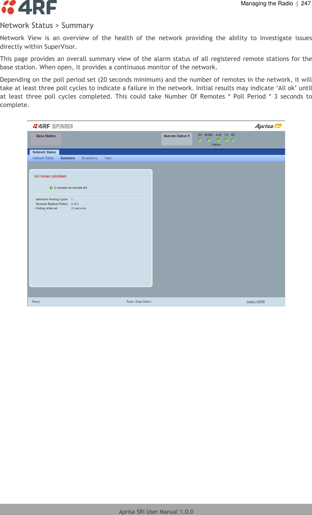
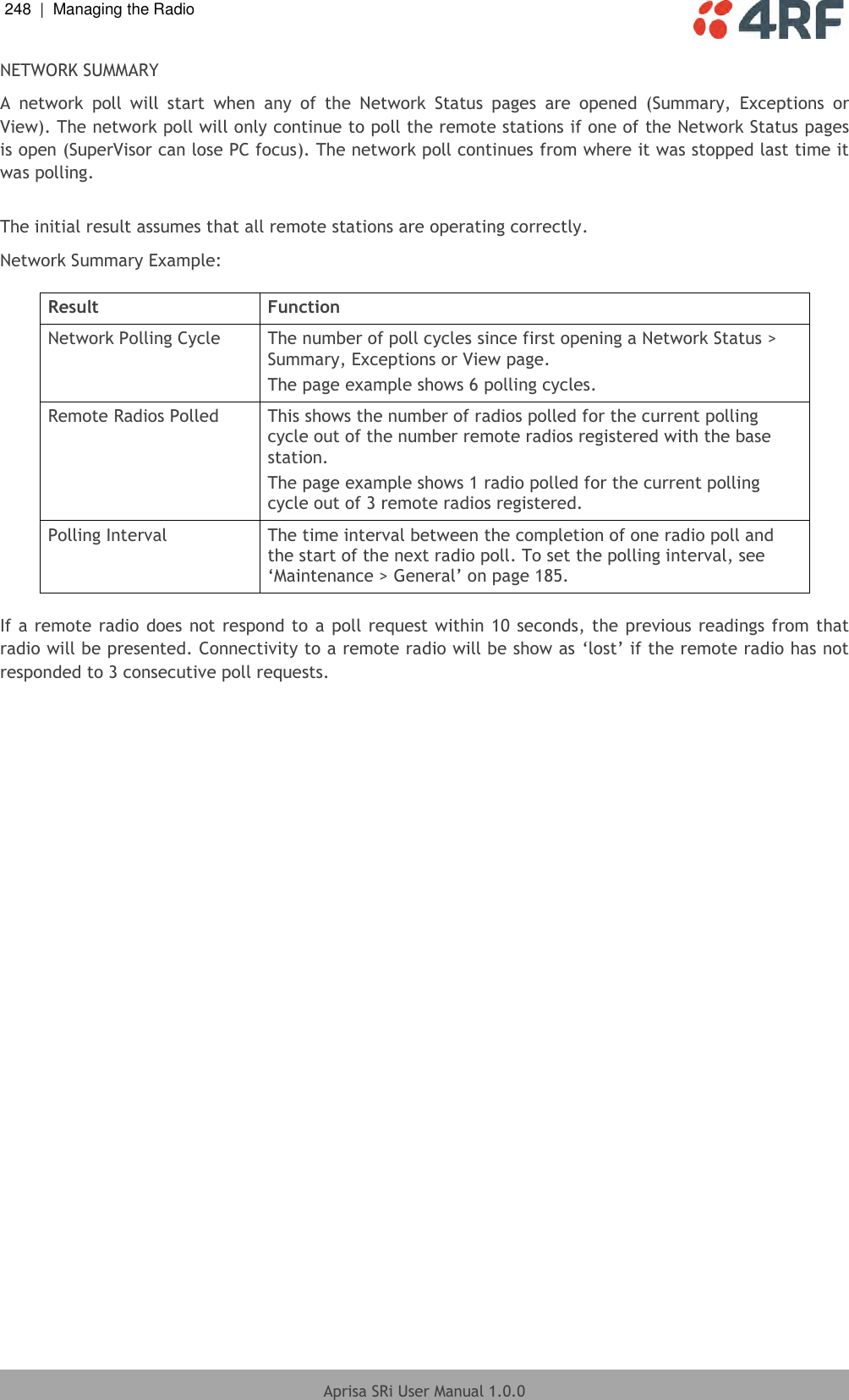
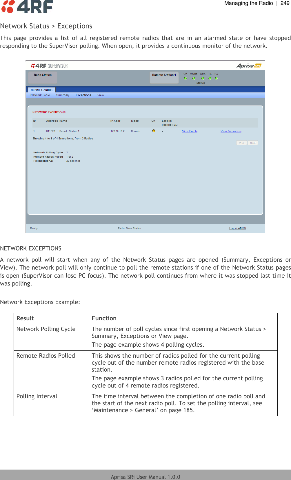
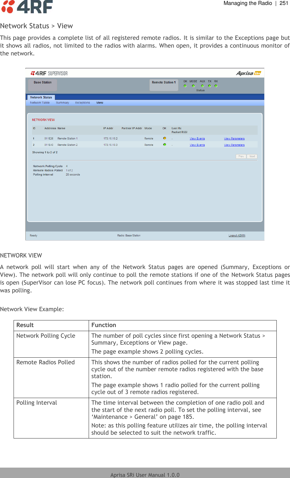
![150 | Managing the Radio Aprisa SRi User Manual 1.0.0 PRIORITY CRITERIA Priority Type Set the layer 2 Ethernet or layer 3 IP packet header priority type fields in the selected profile classification rules. Priority Type Description None Do not use any layer 2 / 3 Ethernet or IP header priority fields in the selected profile classification rules. PCP Use the layer 2 Ethernet header priority field of PCP (Priority Code Point) VLAN priority bits (per IEEE 802.1p/q) in the selected profile classification rules. DSCP Use the layer 3 IP header TOS field used as DSCP (Differentiated Services Code Point per RFC 2474 and RFC 2475) priority bit in the selected profile classification rules. PCP / DSCP Range As per the ‘priority type’ selection, this parameter sets the PCP priority value/s or DSCP priority value/s fields in the selected profile classification rule. The value can be set to a single priority or a single range (no multiple ranges are allowed), for example, the PCP selected priority value can be 7 or a range of priority values like 4-7. The following table shows the layer 2 packet VLAN tag header PCP priority field values PCP Value (Decimal) PCP Priority Priority Level 7 Priority [7] Highest 6 Priority [6] 5 Priority [5] 4 Priority [4] 3 Priority [3] 2 Priority [2] 1 Priority [1] 0 Priority [0] Lowest](https://usermanual.wiki/4RF/SI902M160/User-Guide-3092666-Page-152.png)
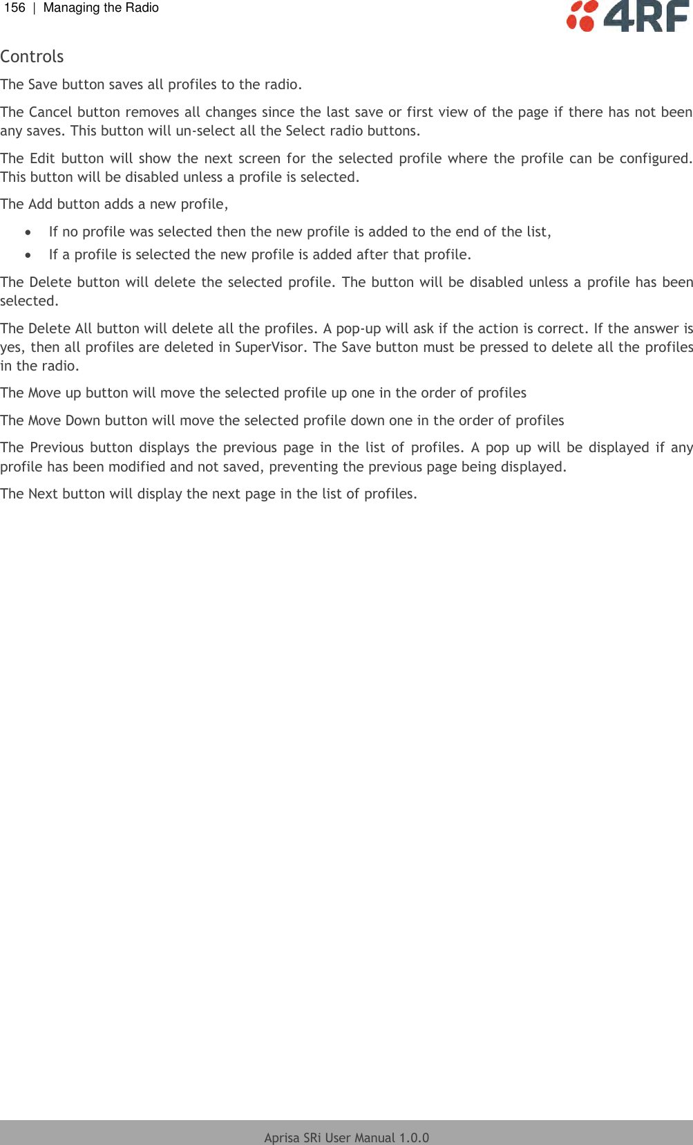
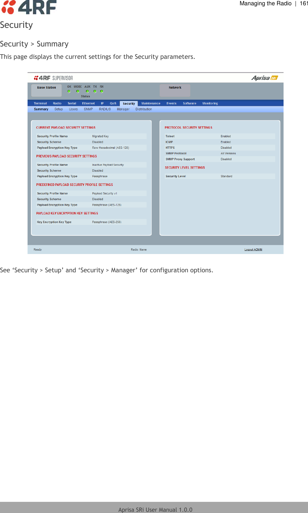
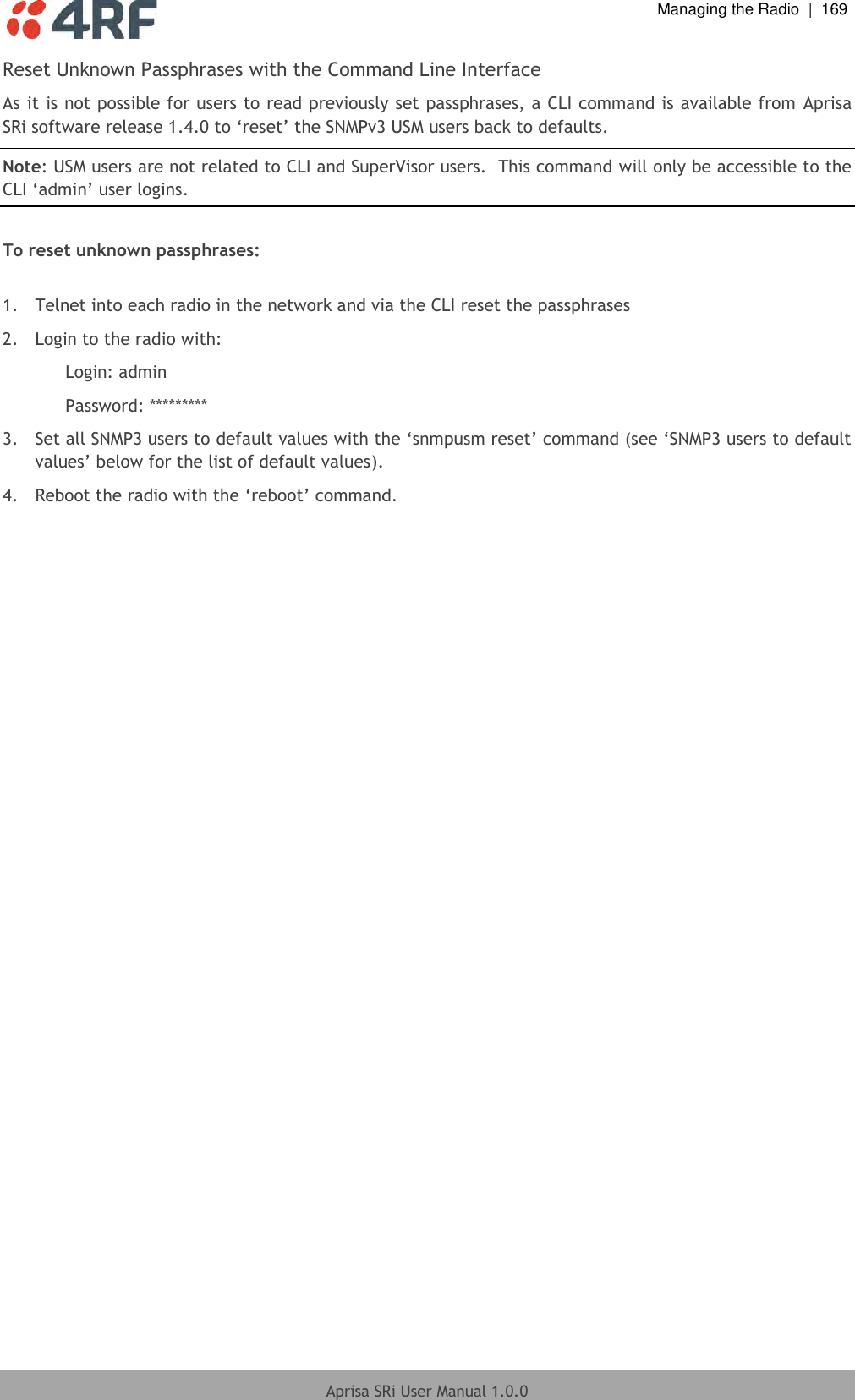
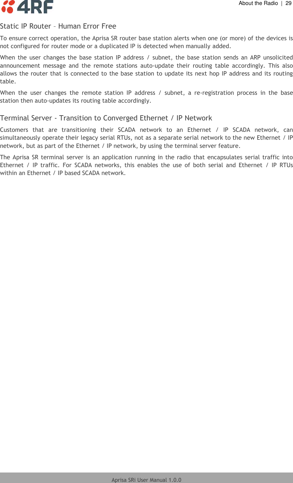
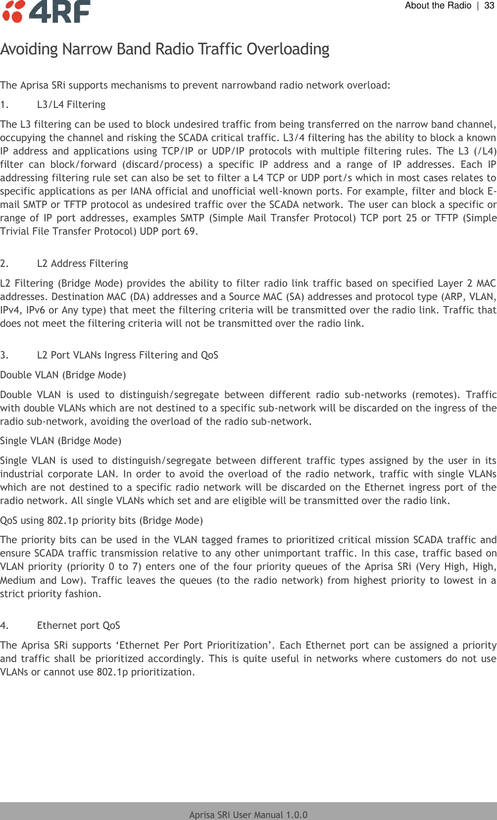
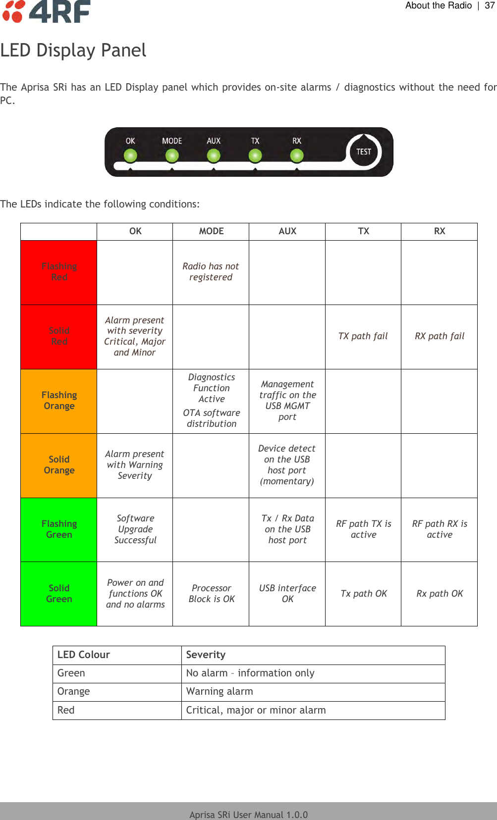
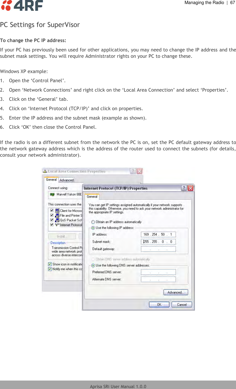
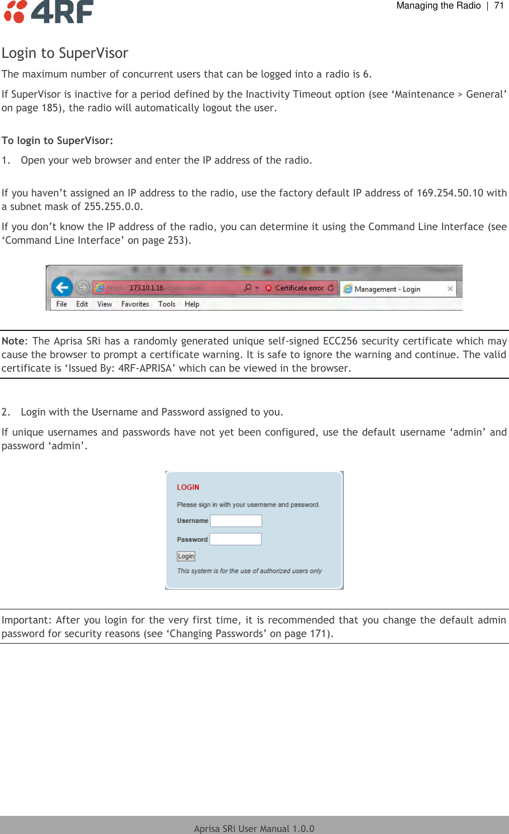
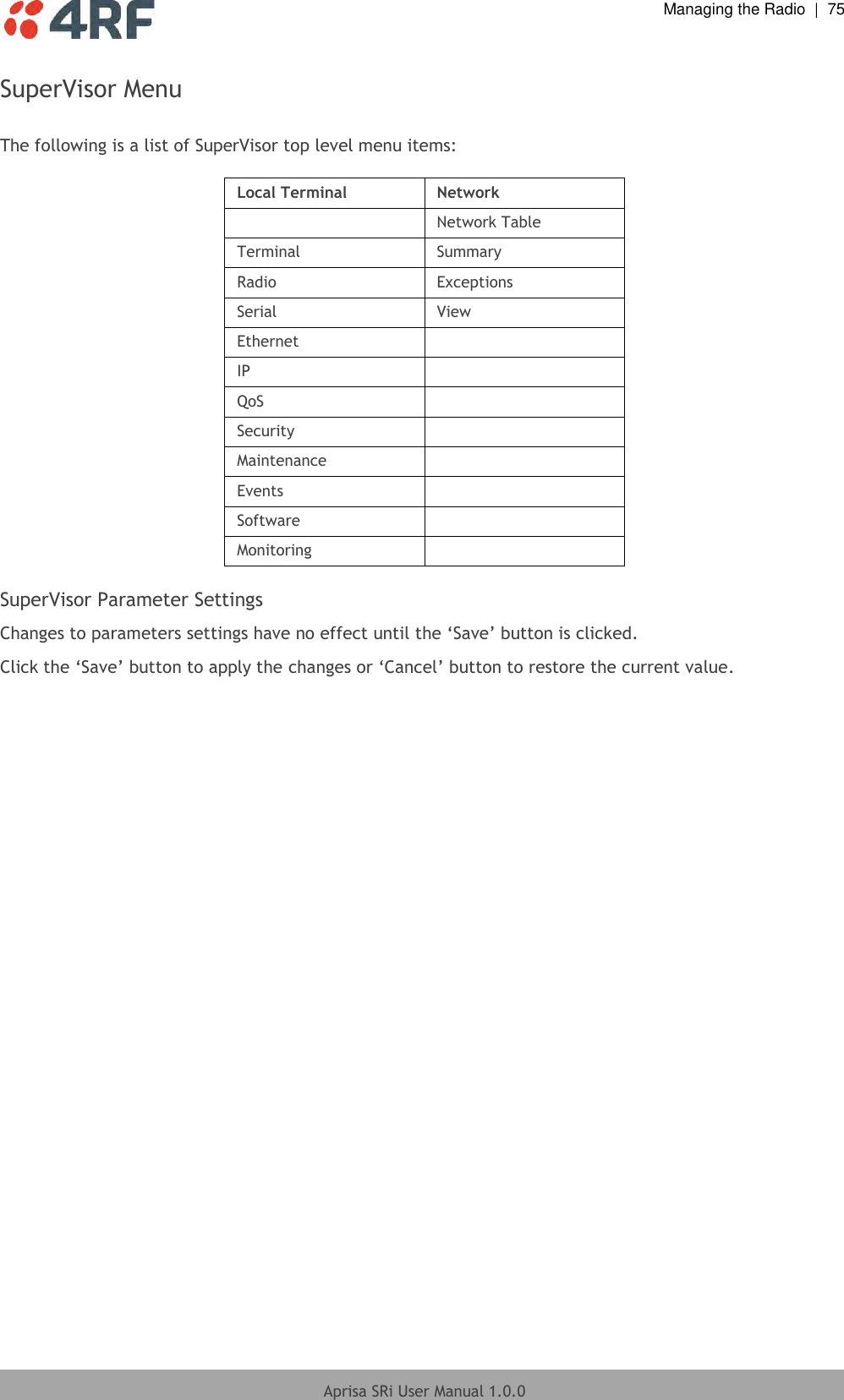
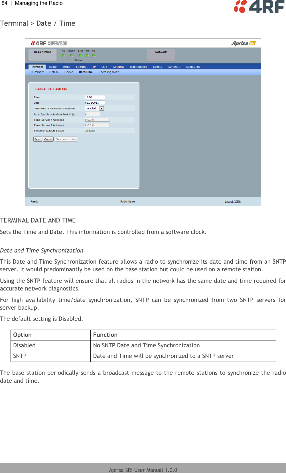
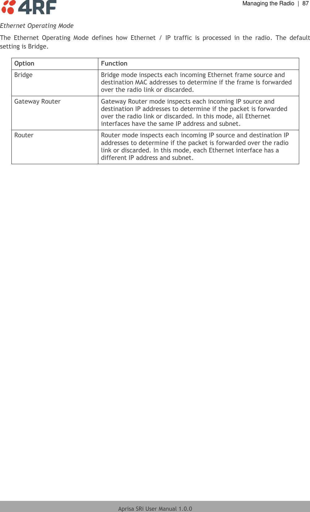
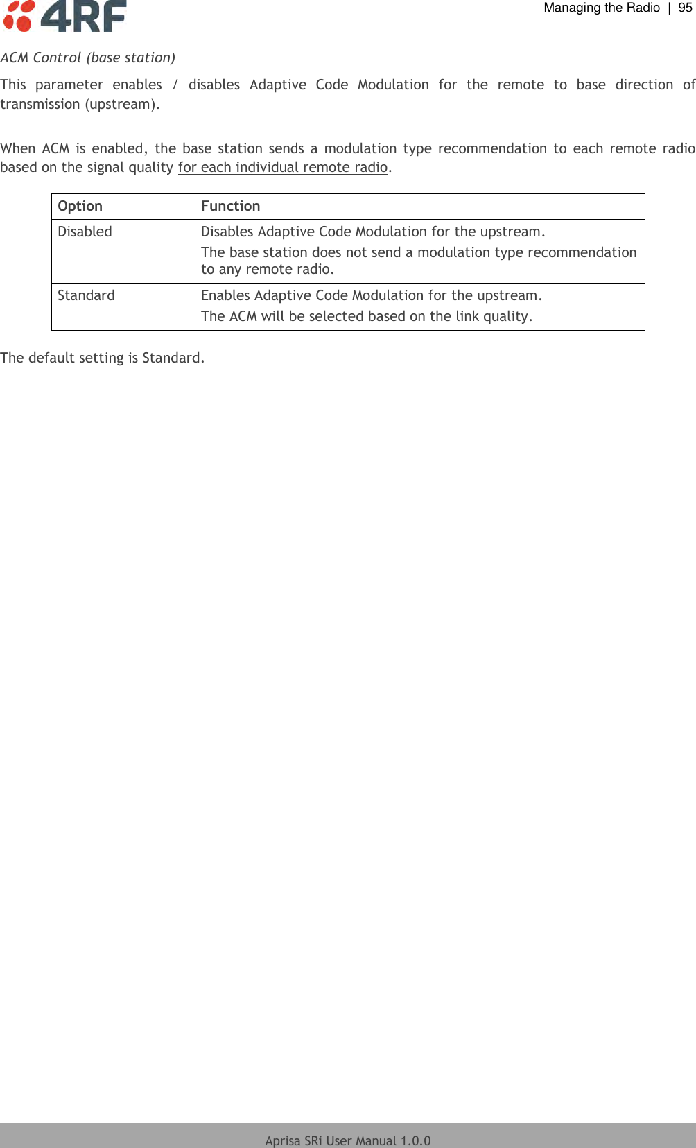
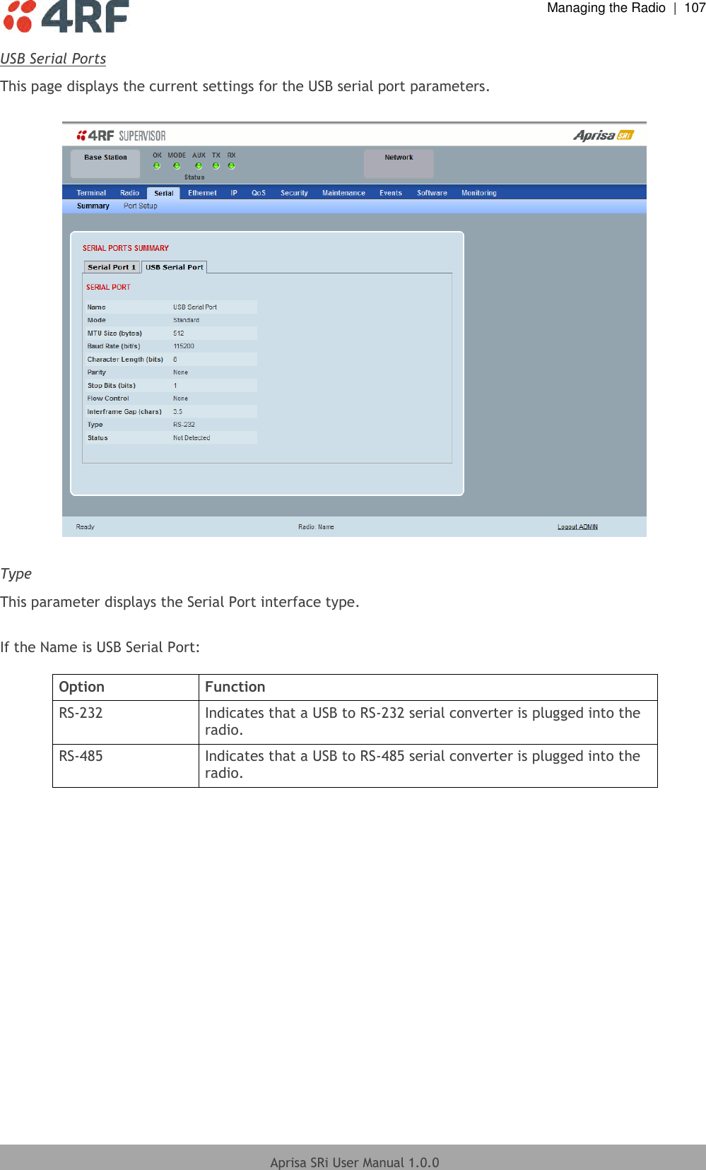
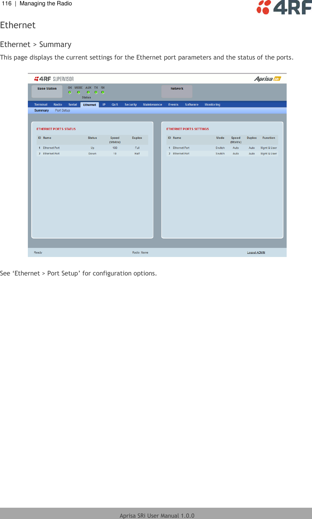
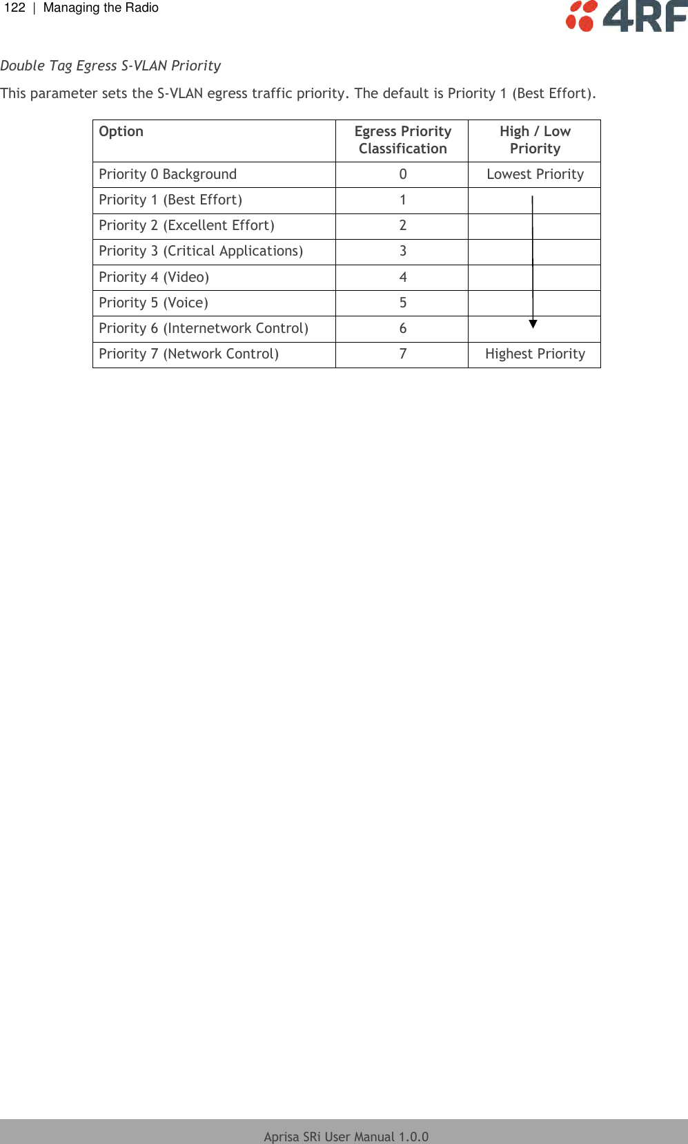
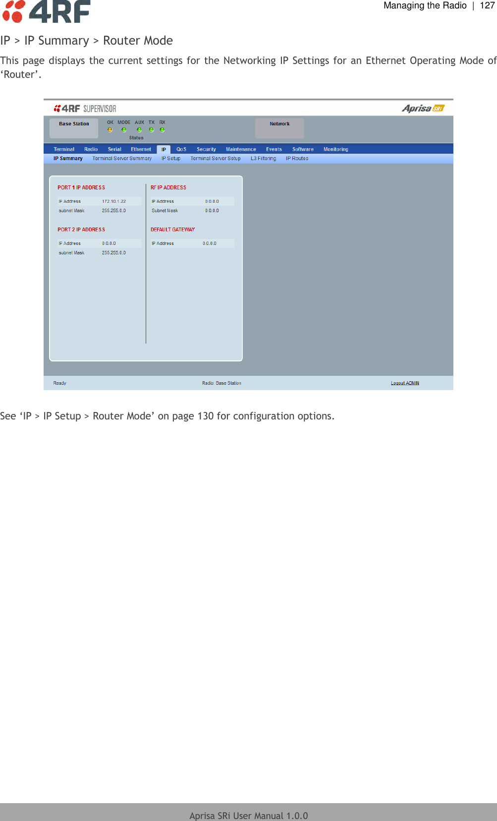
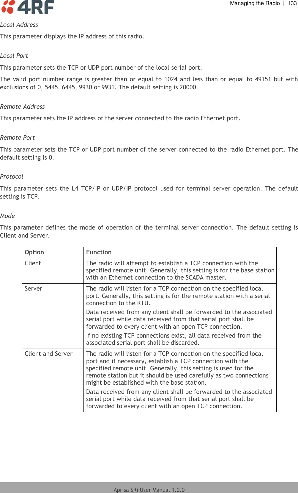
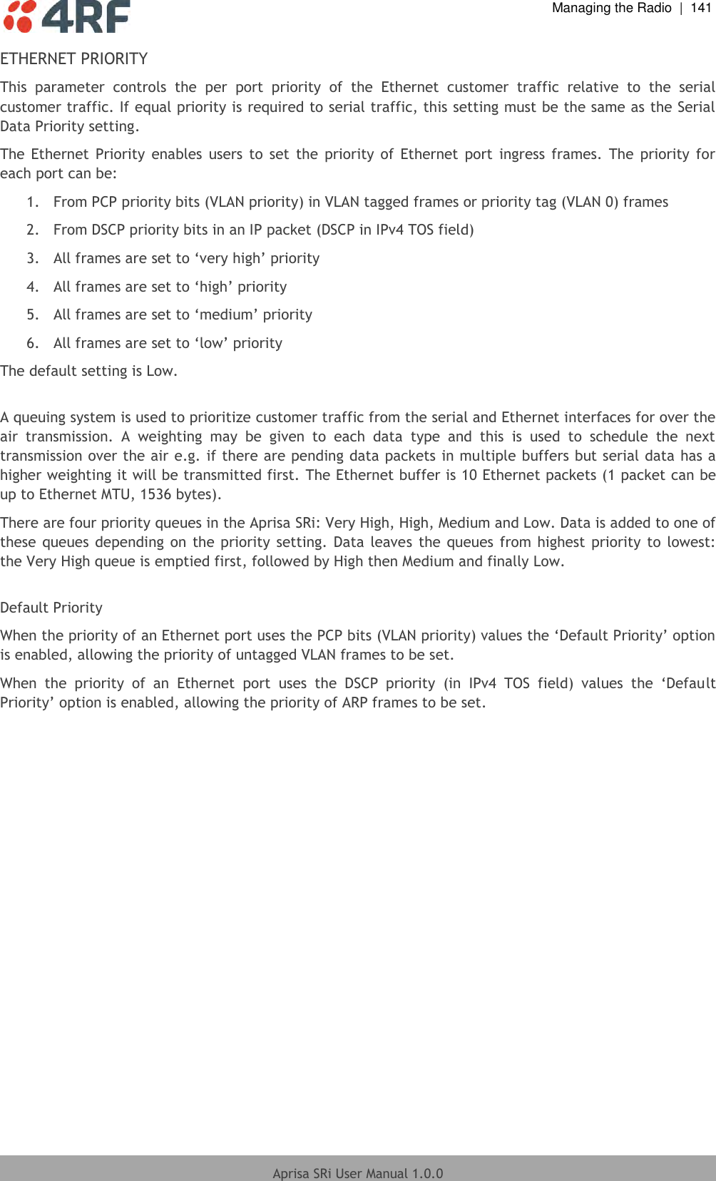
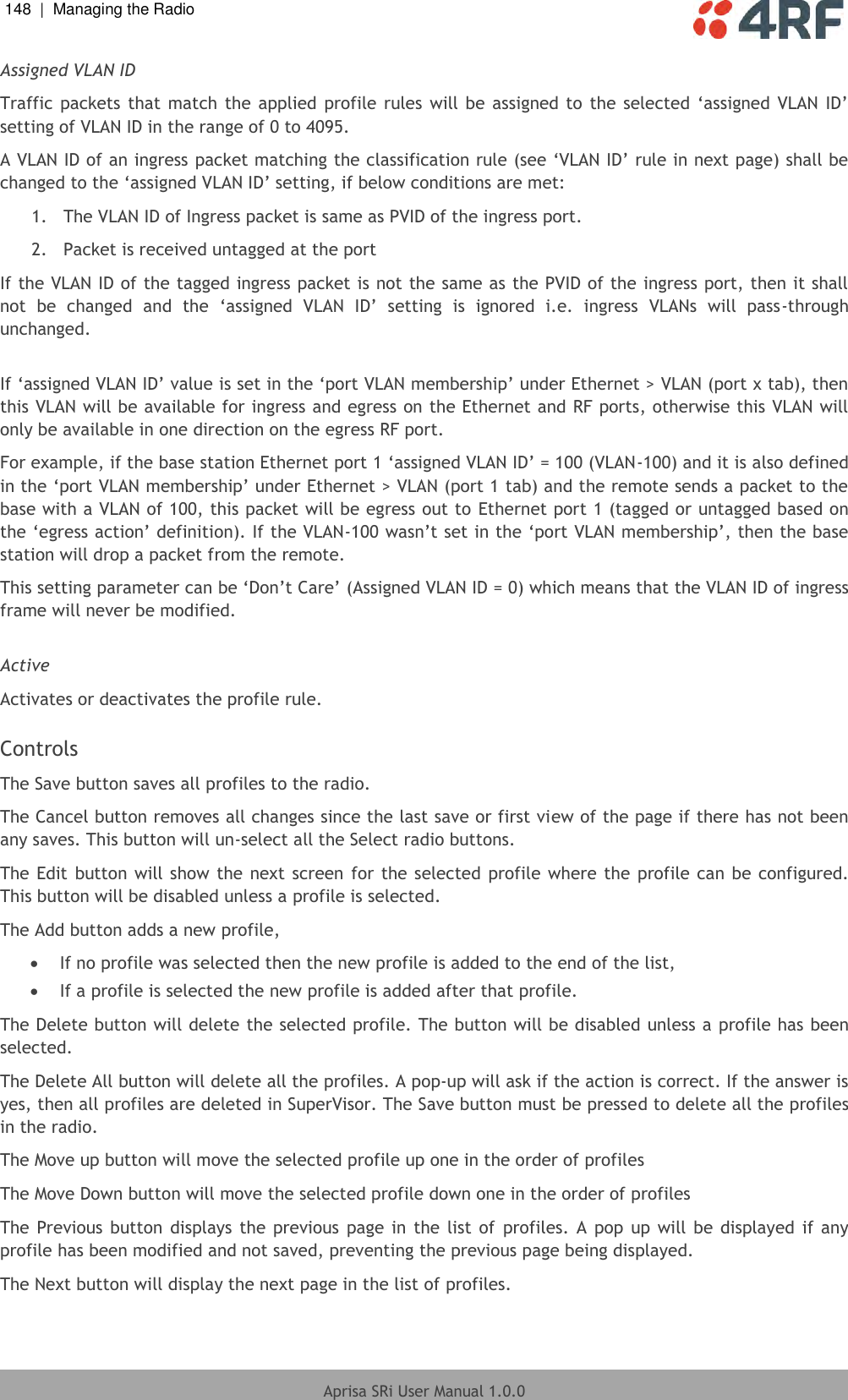
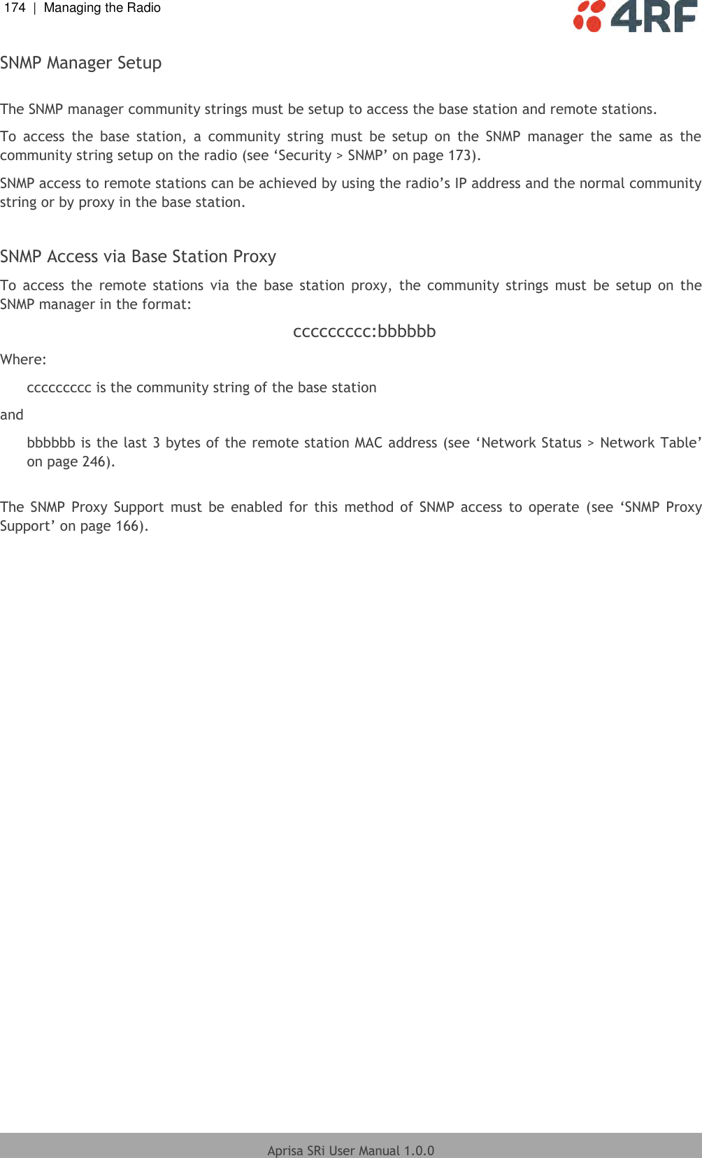
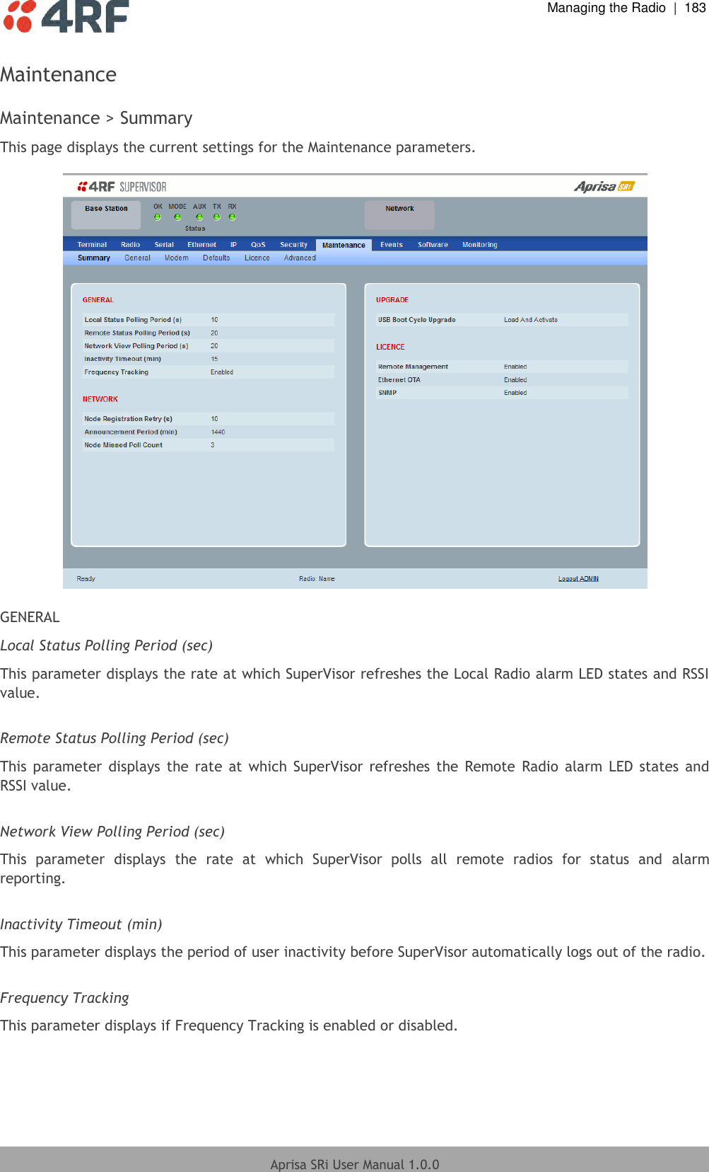
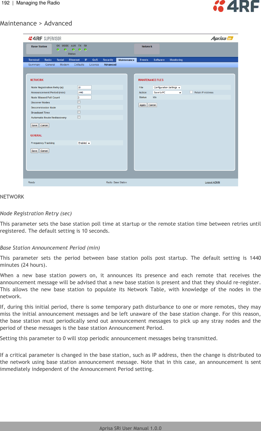
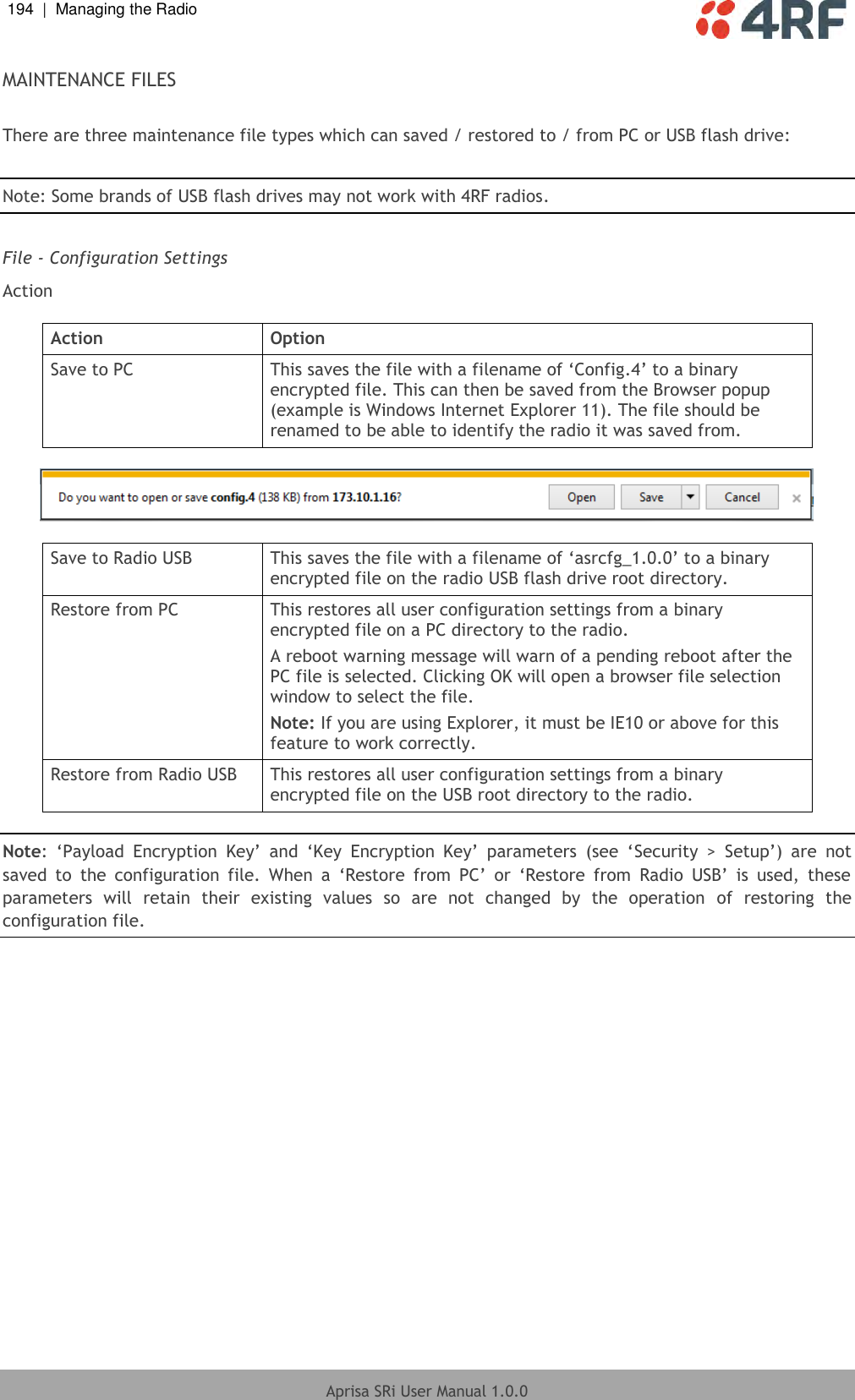
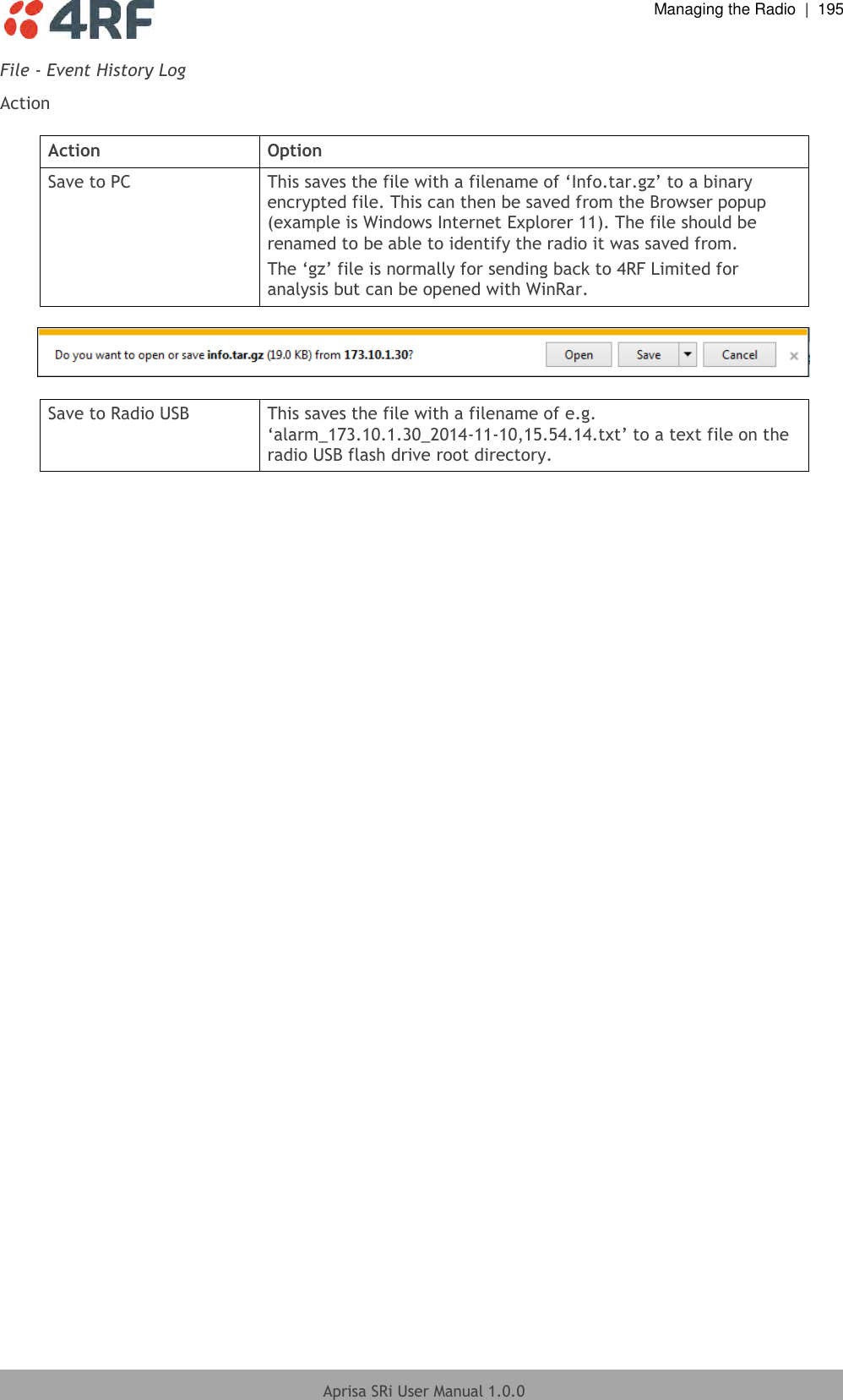
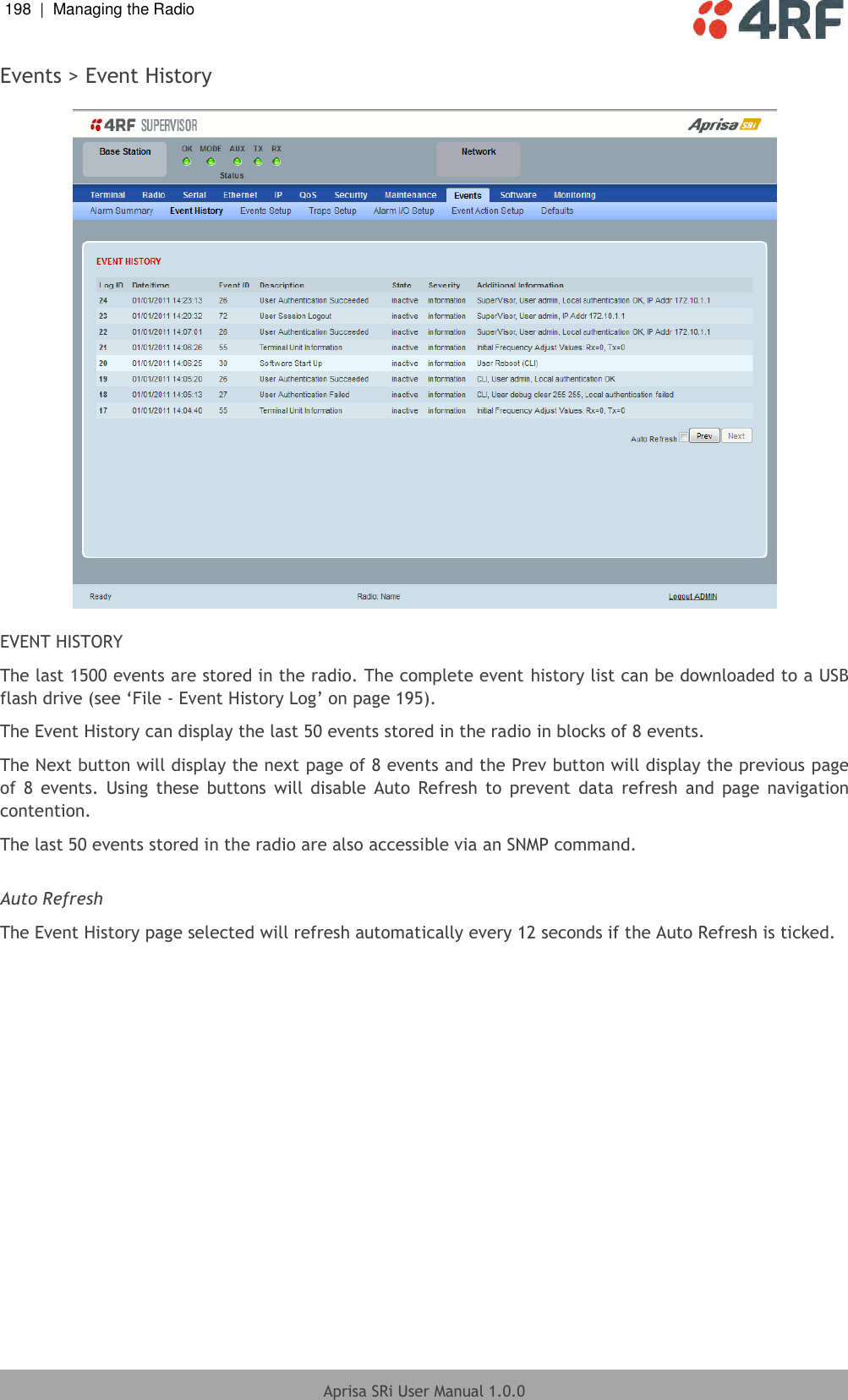
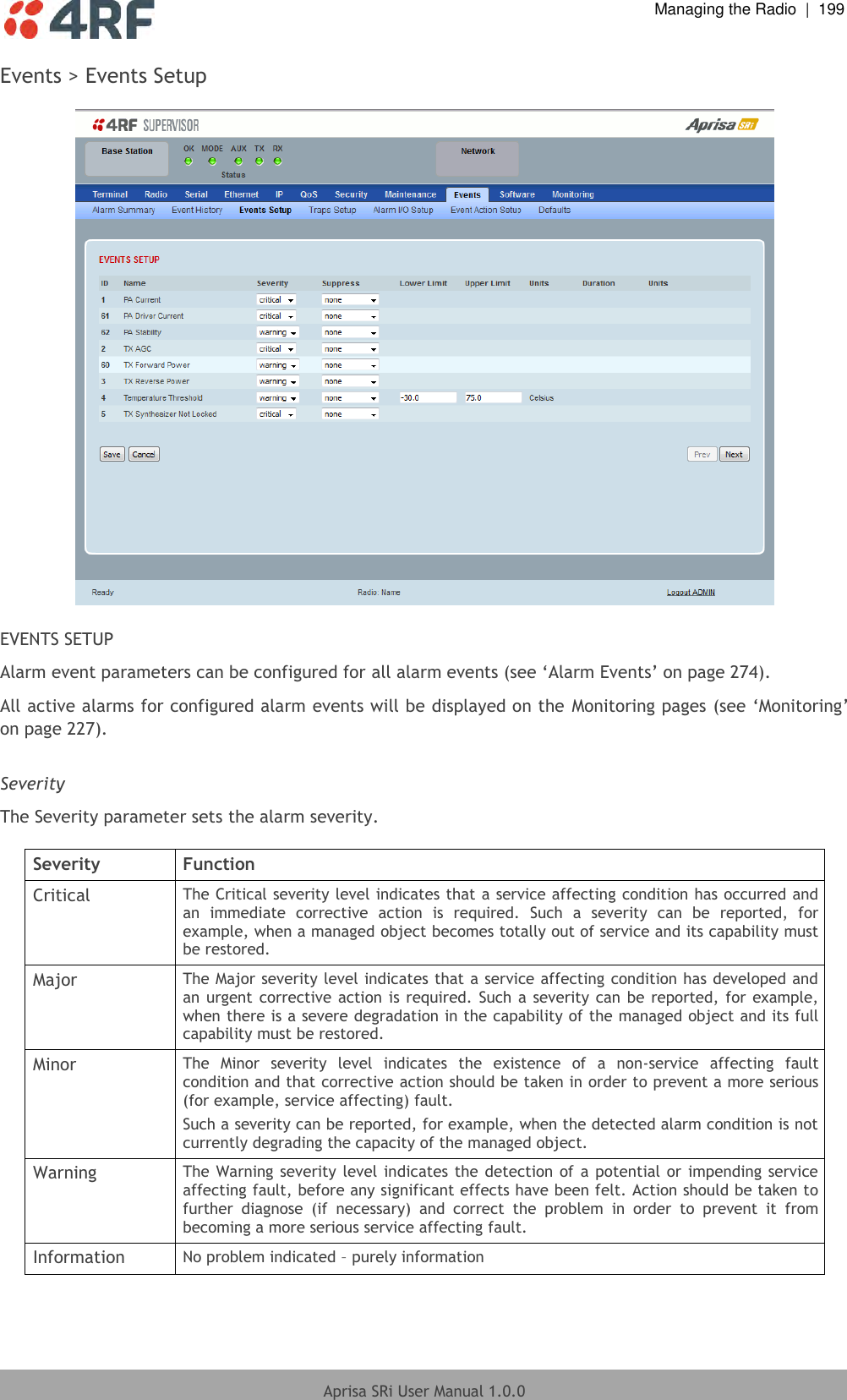
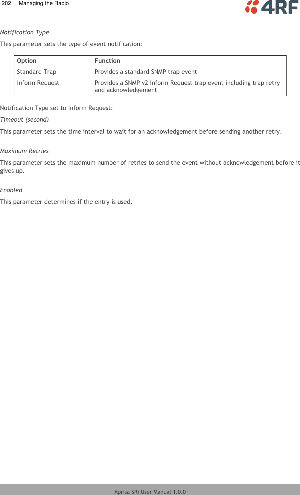
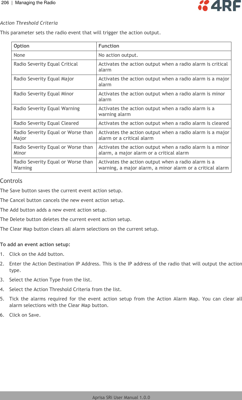
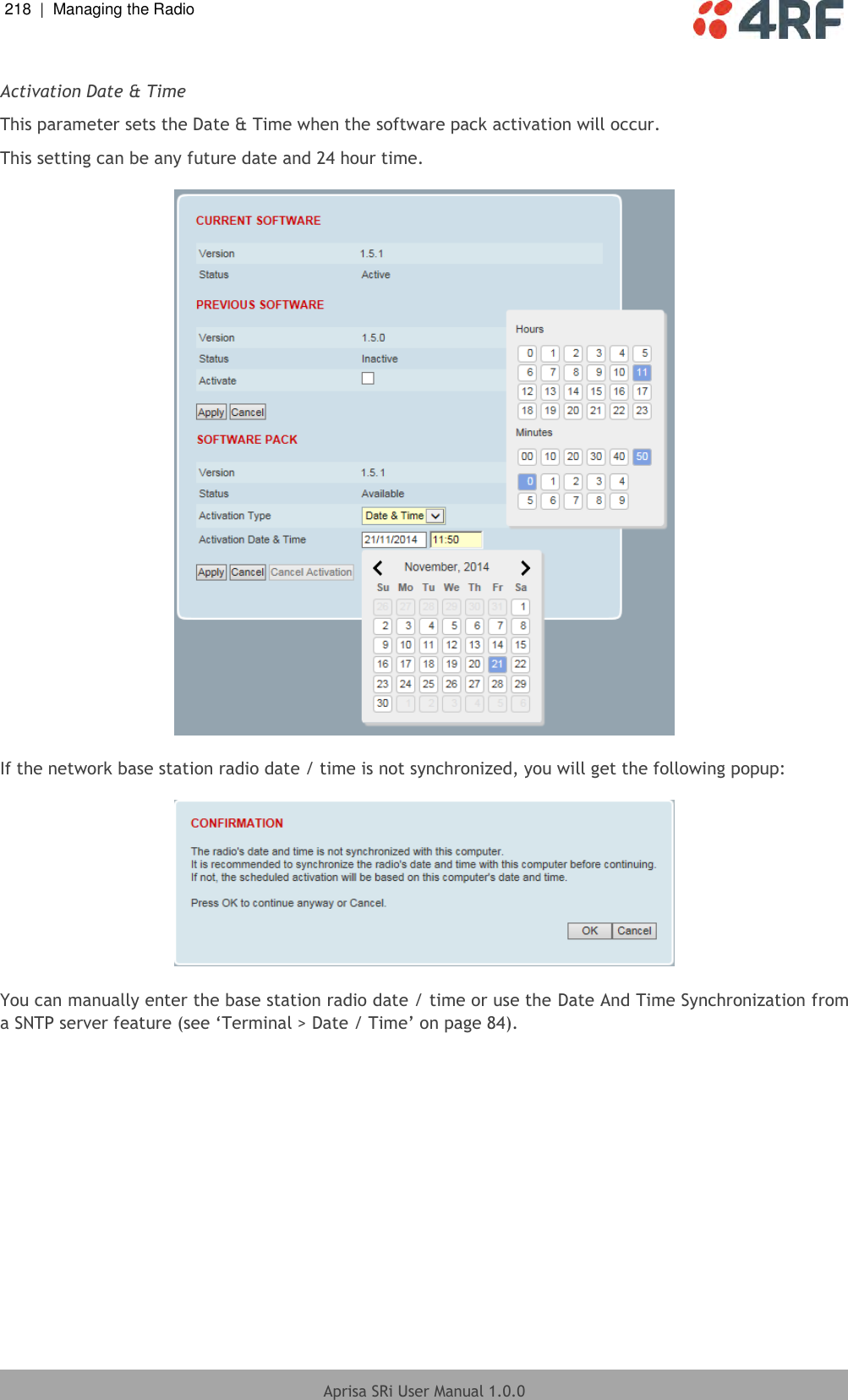
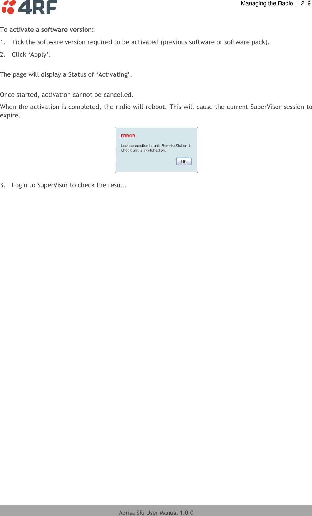
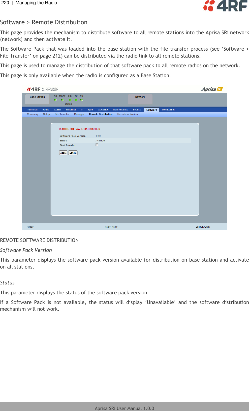
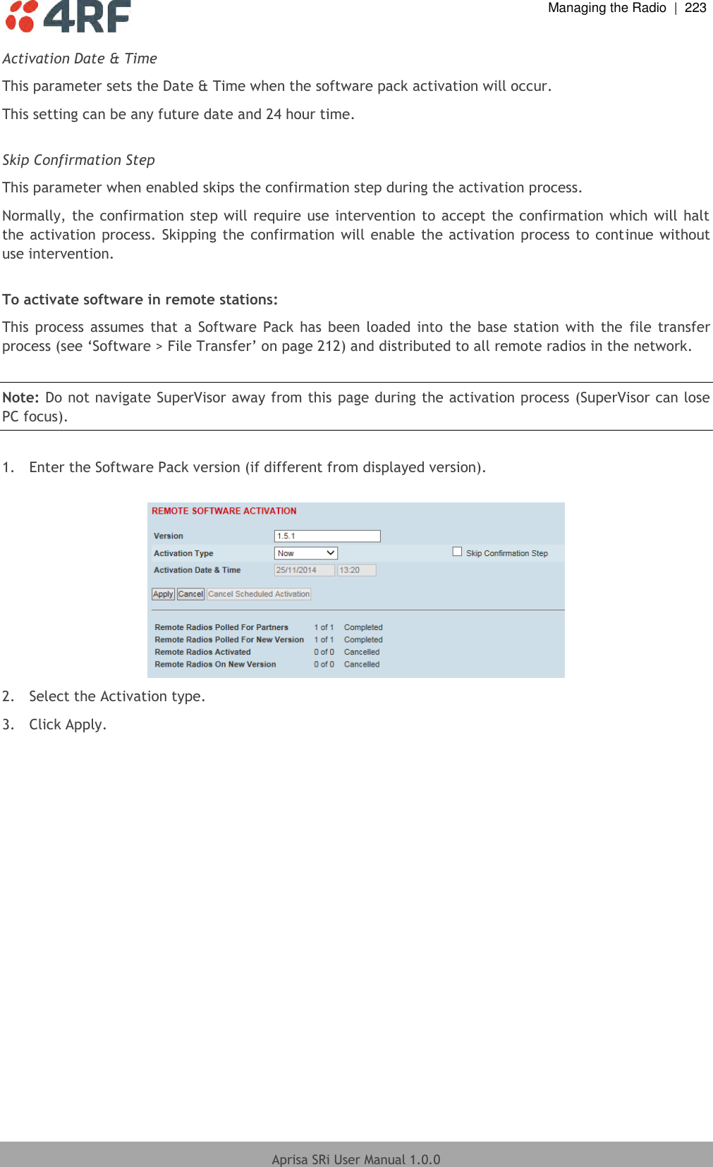
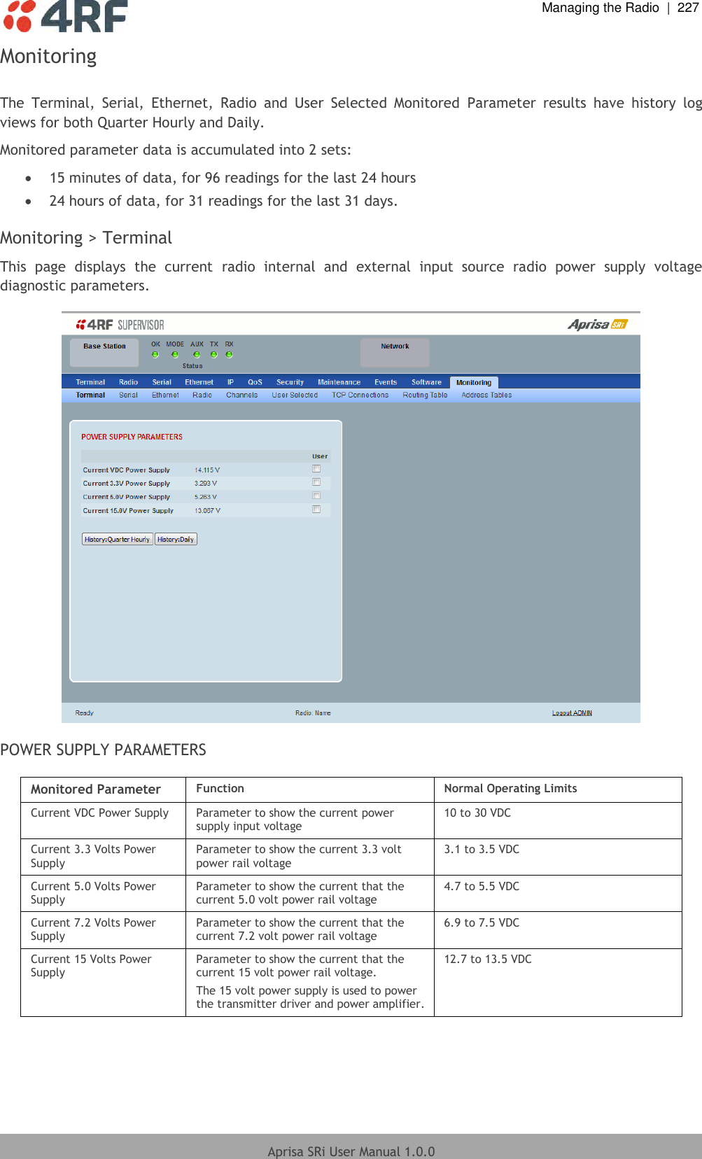
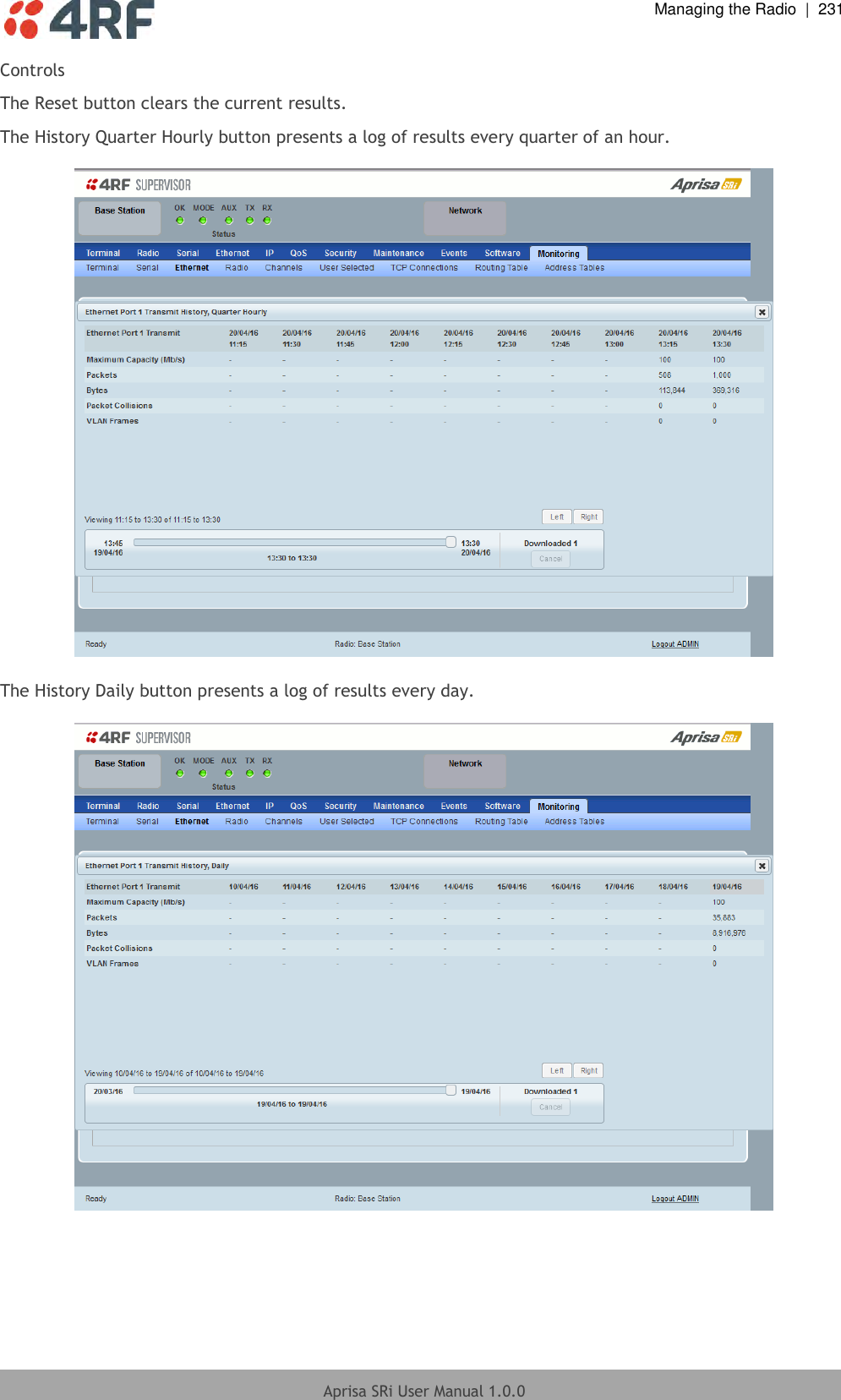
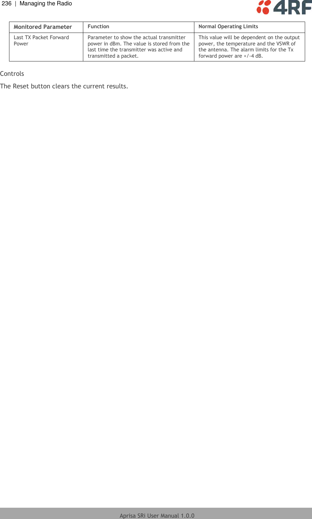
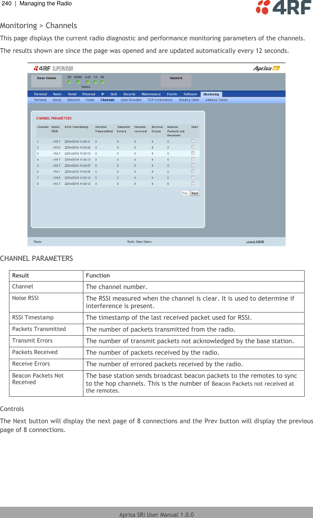
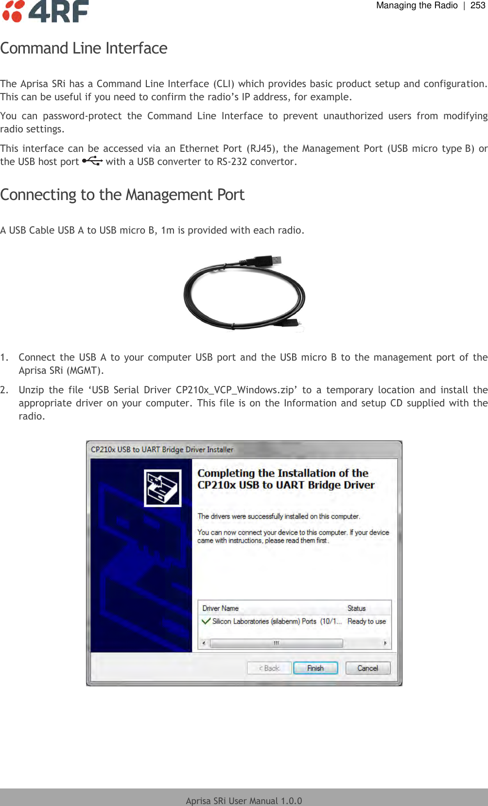
![Managing the Radio | 171 Aprisa SRi User Manual 1.0.0 Security > Users Note: You must login with ‘admin’ privileges to add, disable, delete a user or change a password. USER DETAILS Shows a list of the current users setup in the radio. ADD NEW USER To add a new user: 1. Enter the Username. A username can be up to 32 characters but cannot contain back slashes, forward slashes, spaces, tabs, single or double quotes. Usernames are case sensitive. 2. Enter the Password. A password can be 8 to 32 printable characters but cannot contain a tab. Passwords are case sensitive. Good password policy: contains at least eight characters, and contains at least one upper case letter, and contains at least one lower case letter, and contains at least one digit or another character such as !@#$%^&(){}[]<>... , and is not a term in a familiar language or jargon, and is not identical to or derived from the accompanying account name, from personal characteristics or from information from one’s family/social circle, and is easy to remember, for instance by means of a key sentence 3. Select the User Privileges](https://usermanual.wiki/4RF/SI902M160/User-Guide-3092666-Page-173.png)

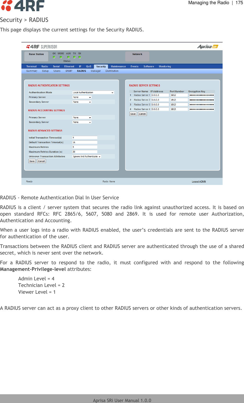


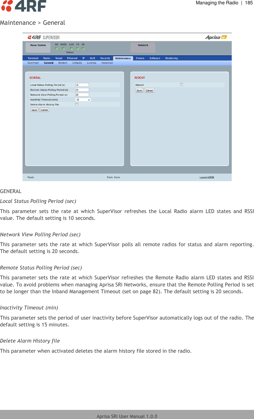


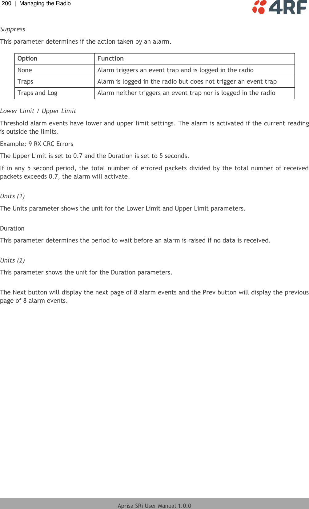
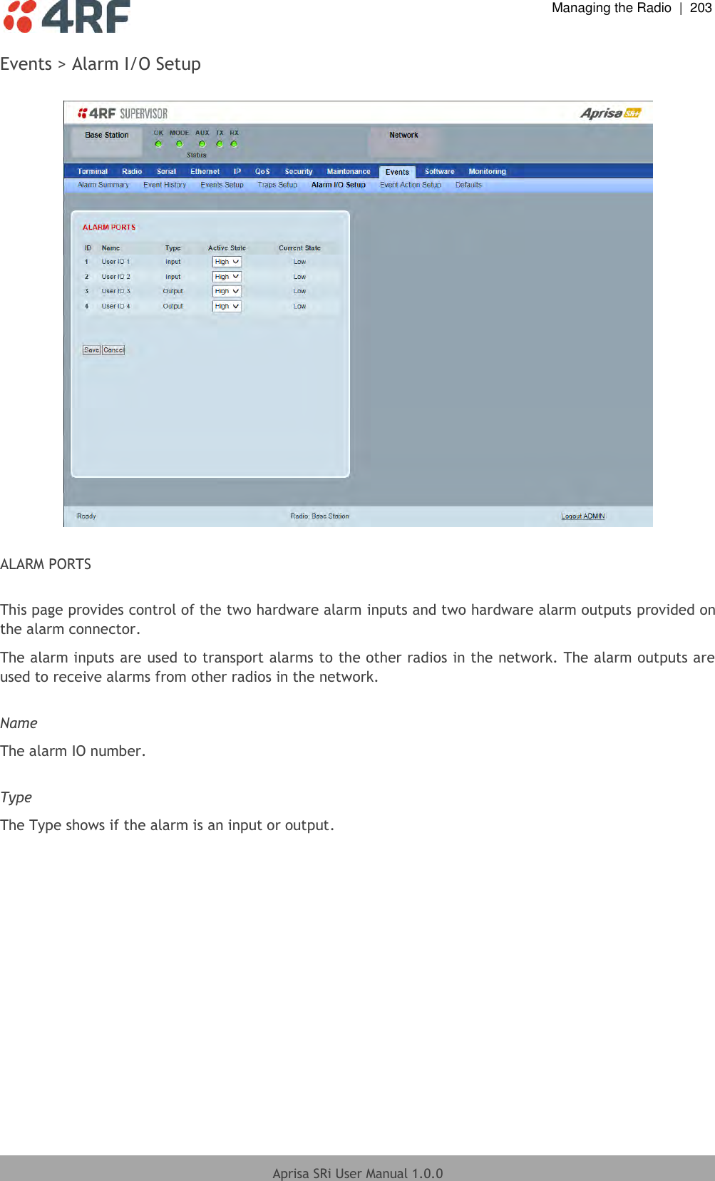
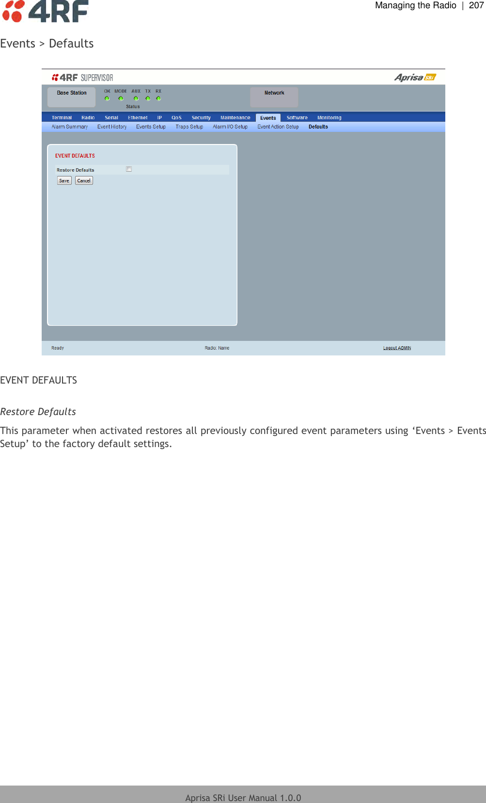

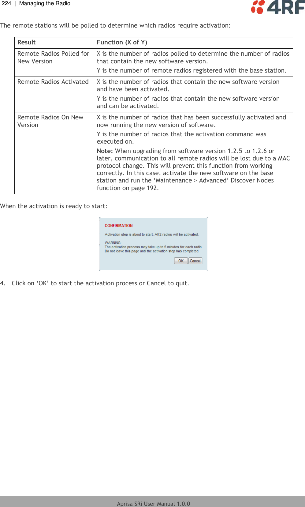
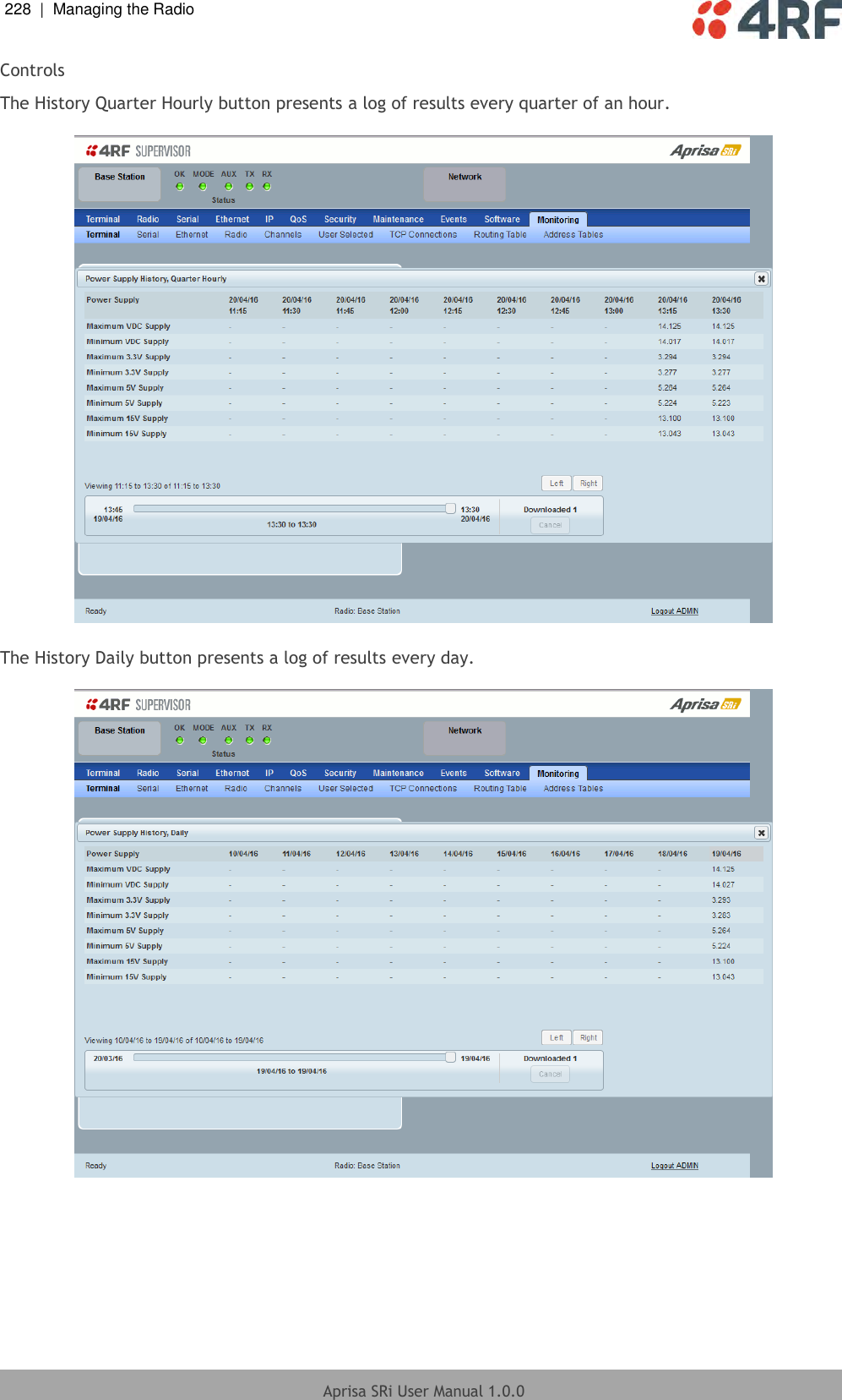
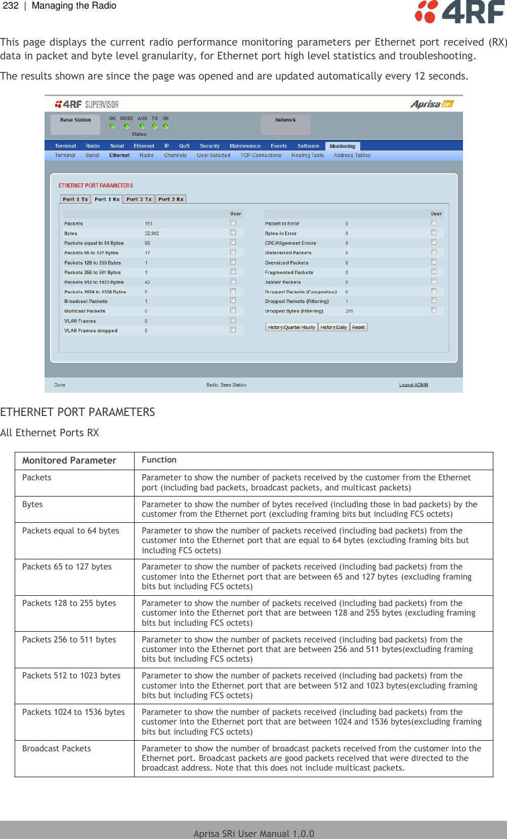

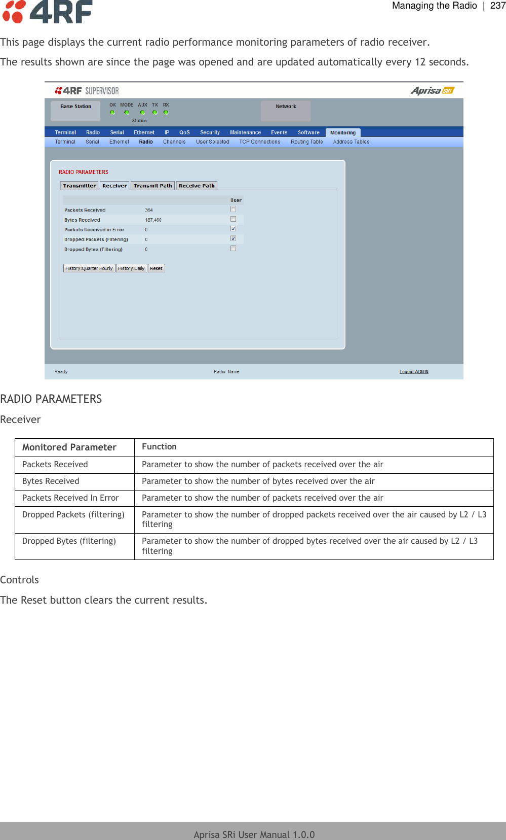
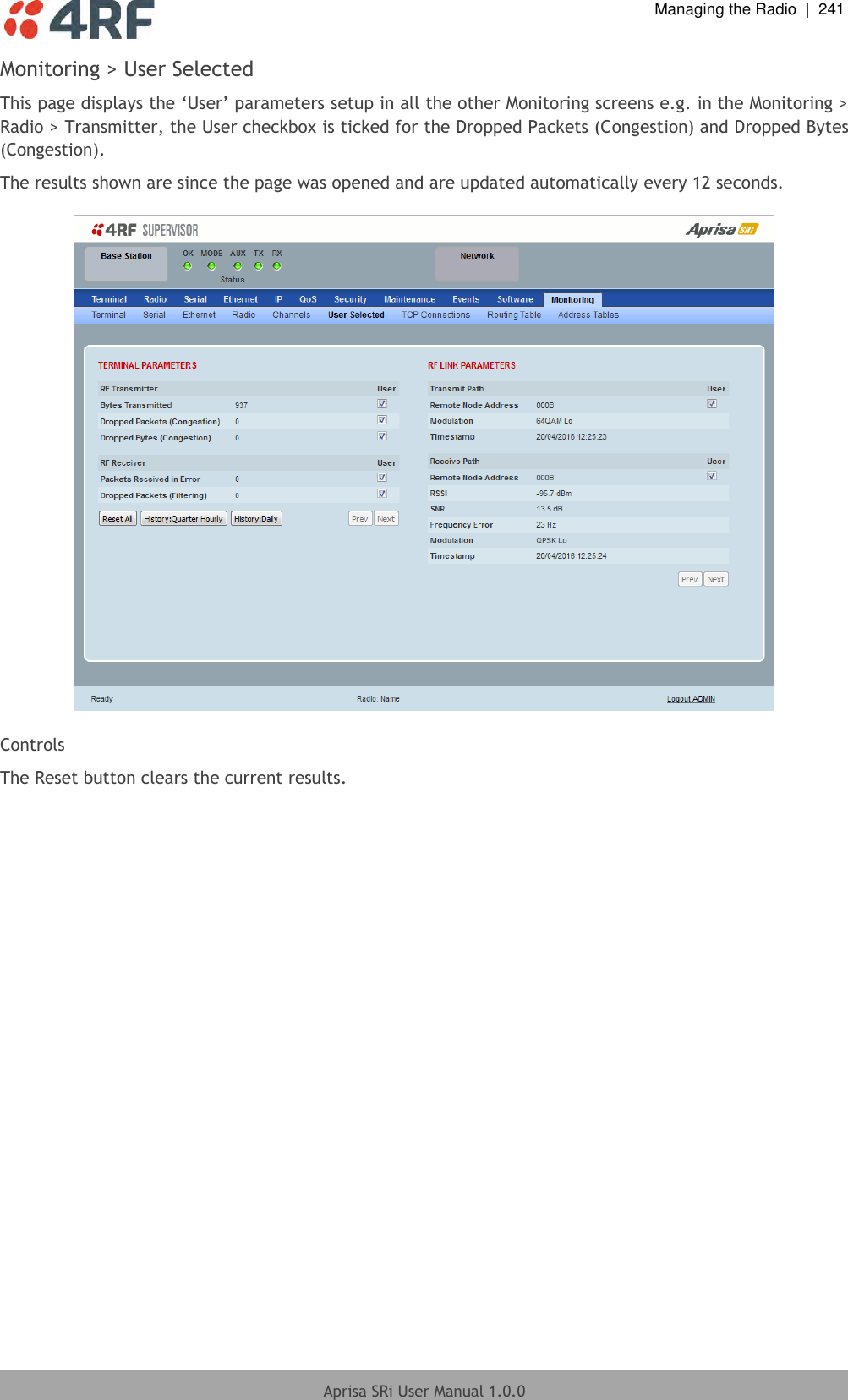

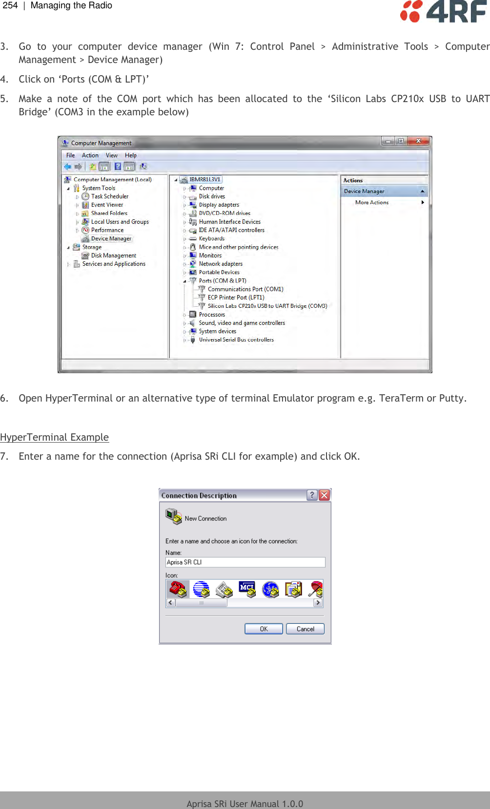
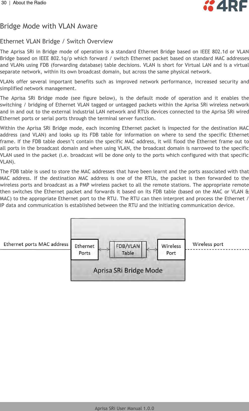
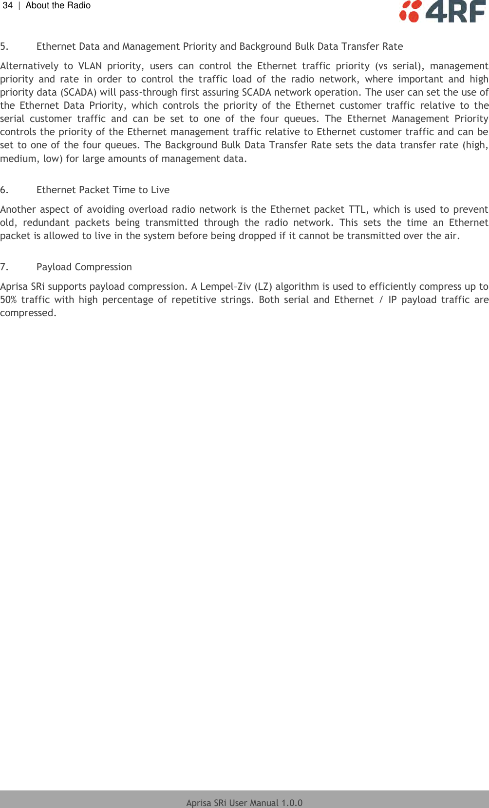
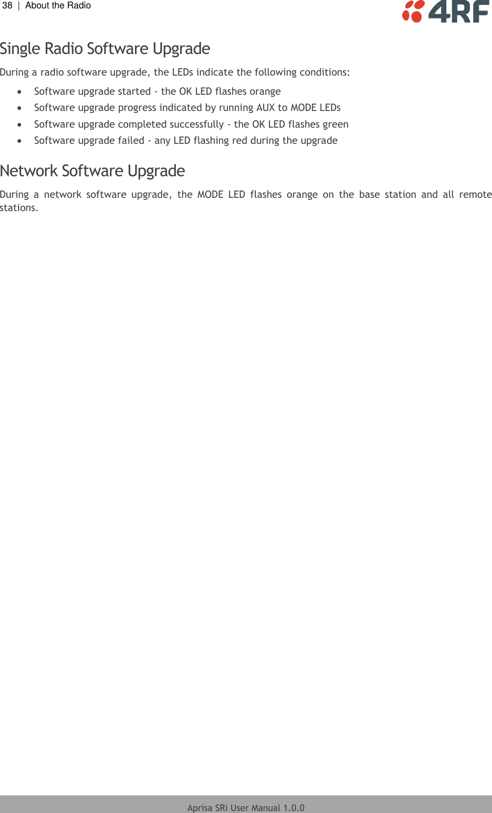
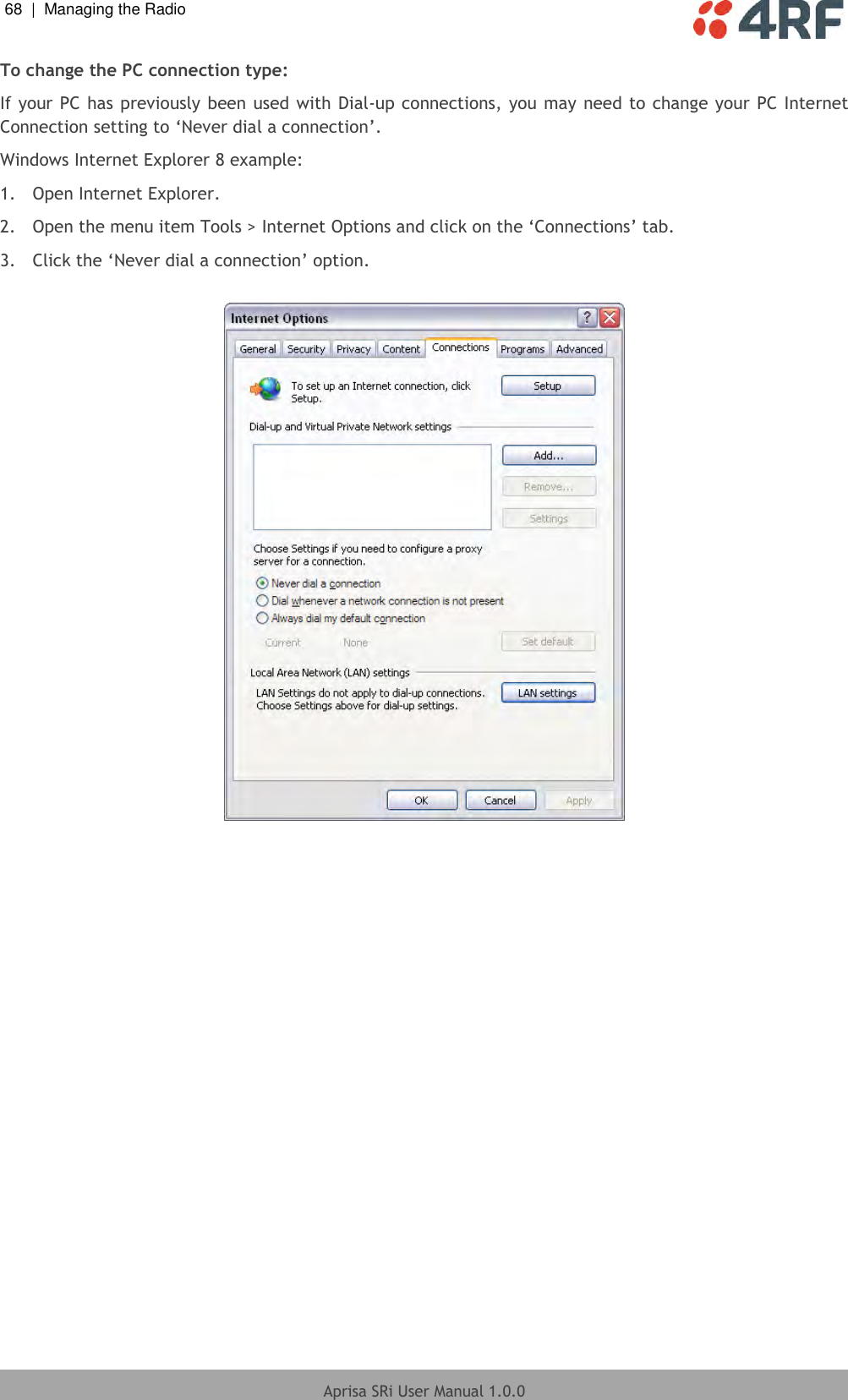
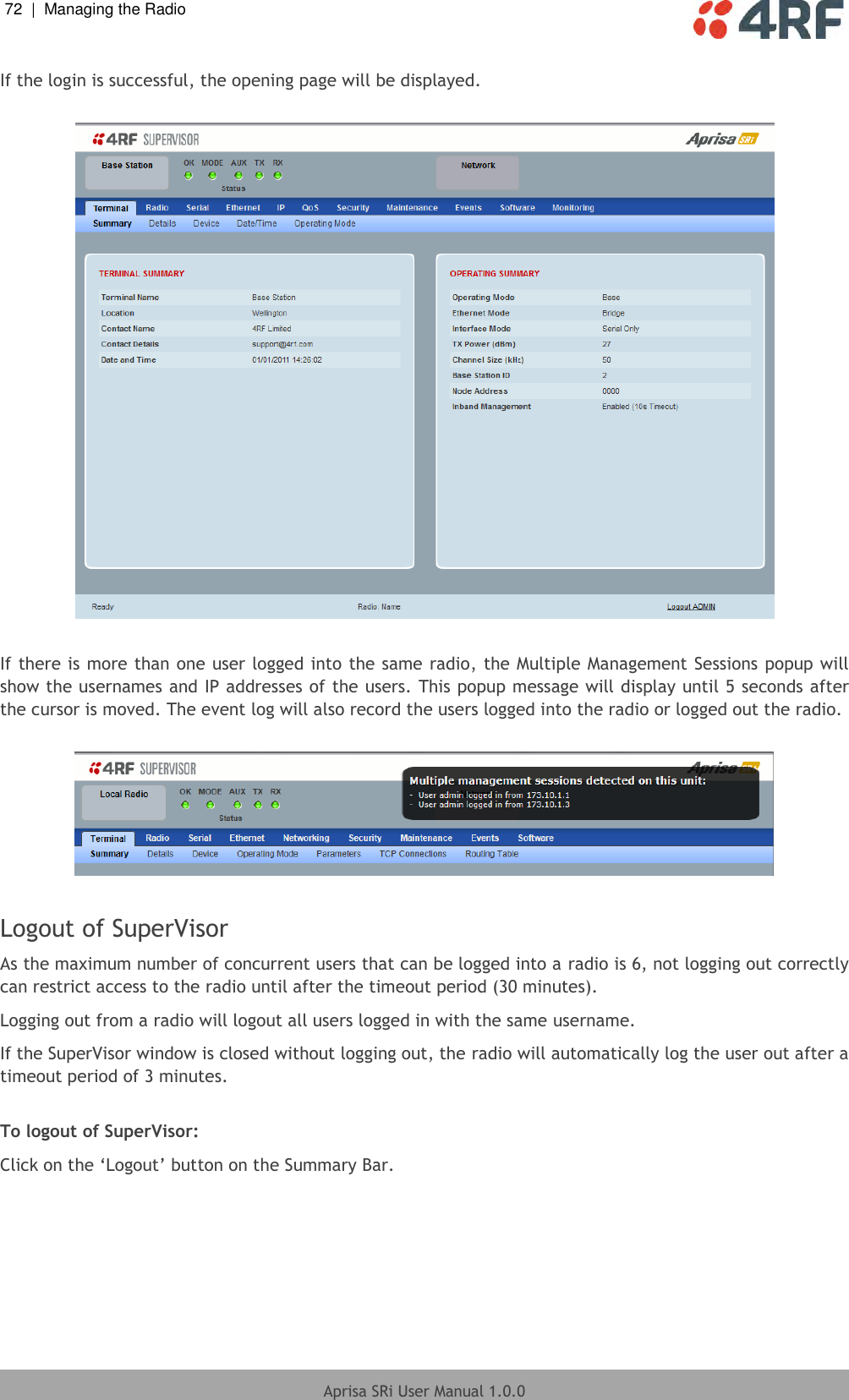
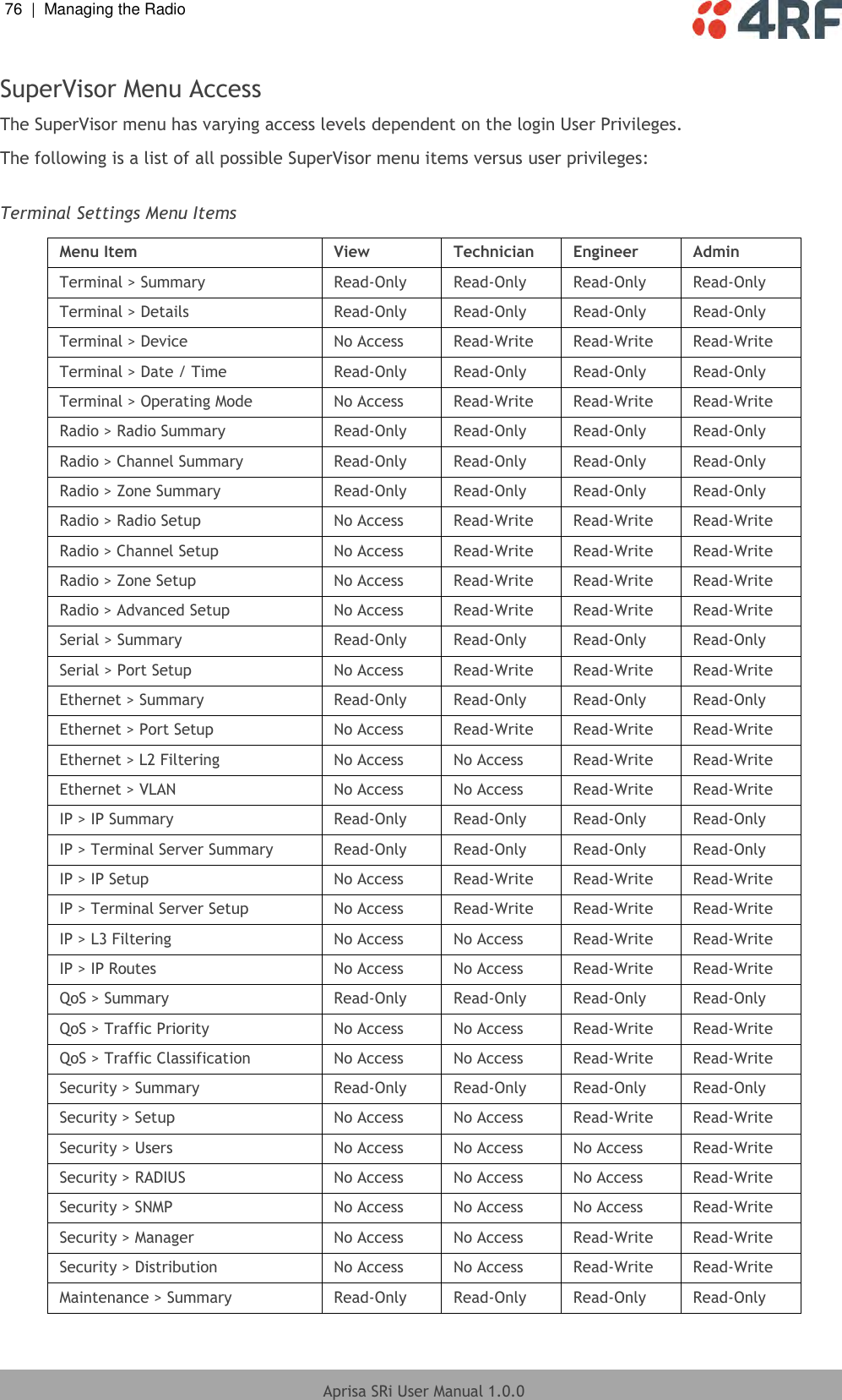
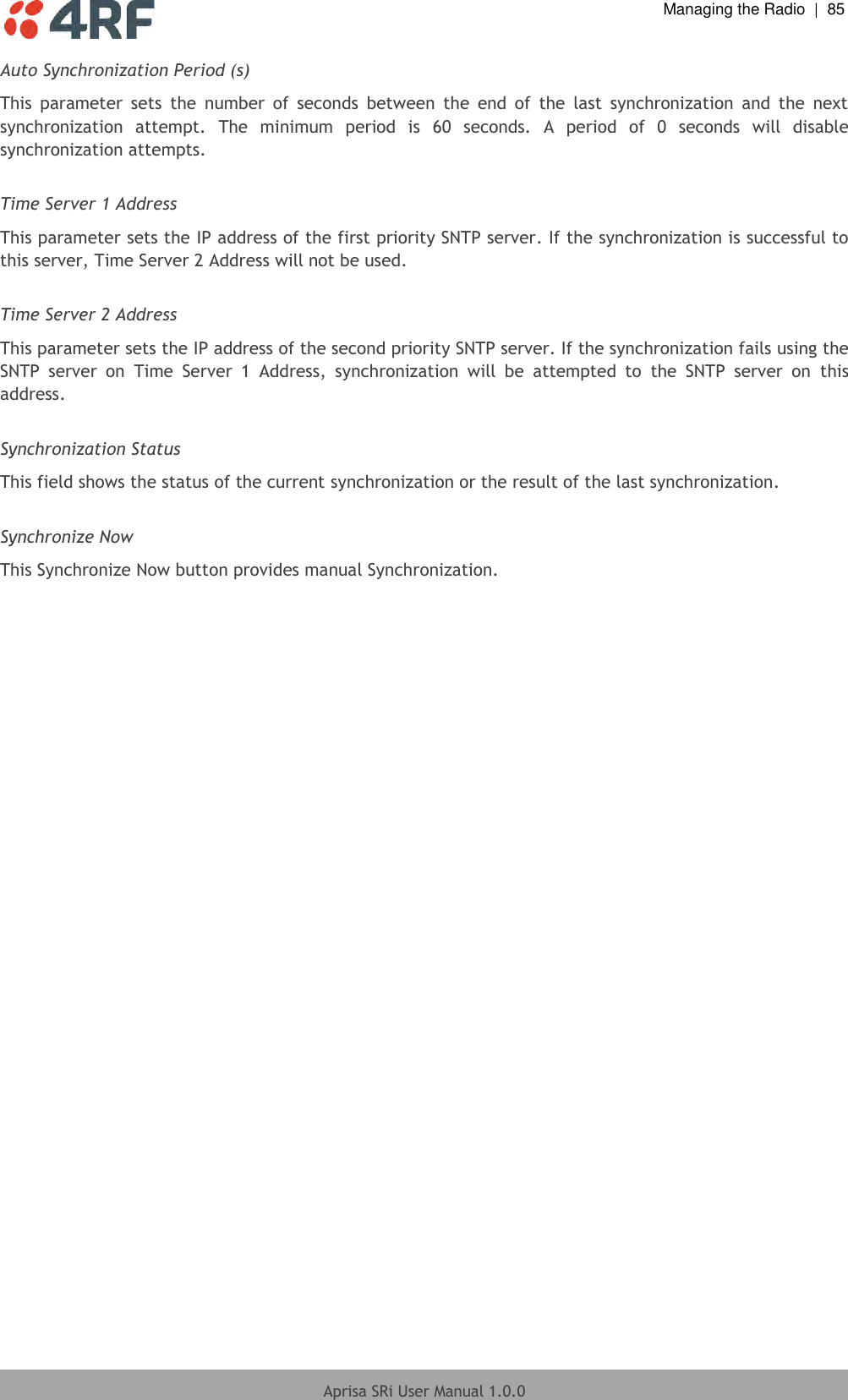
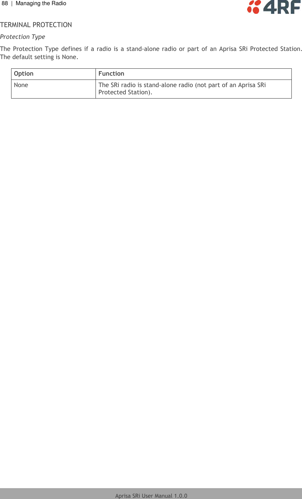
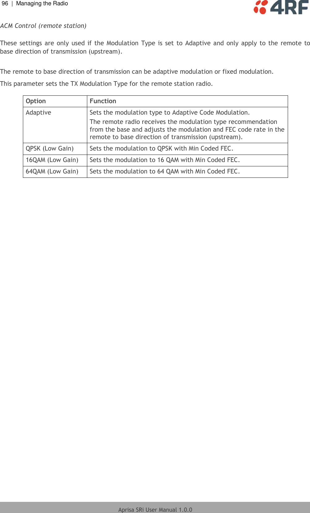
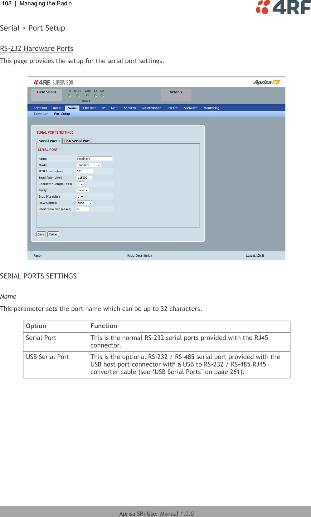
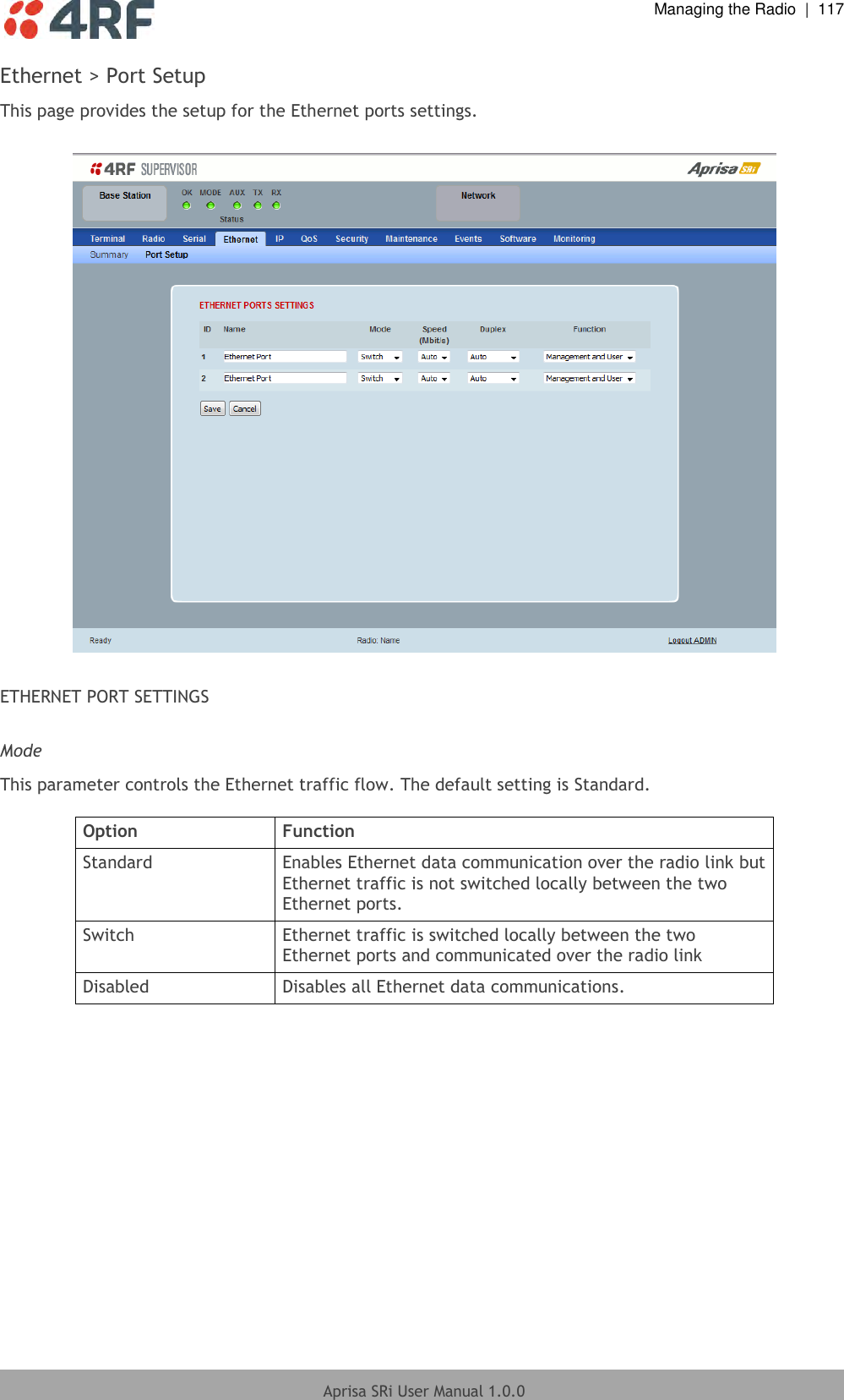
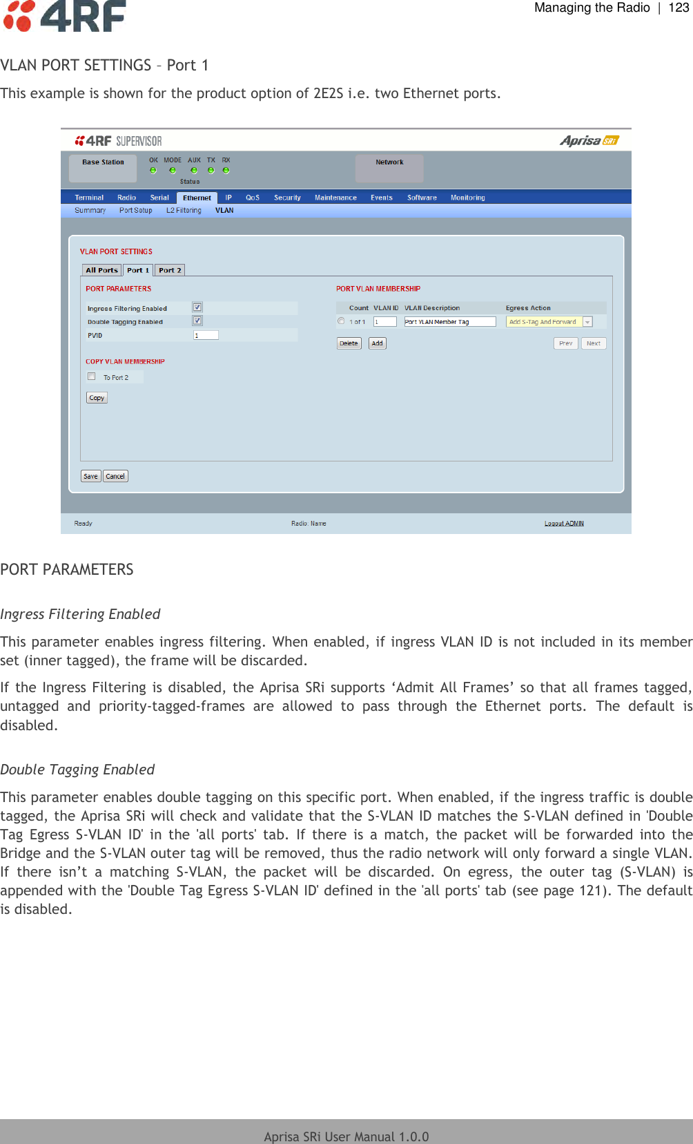
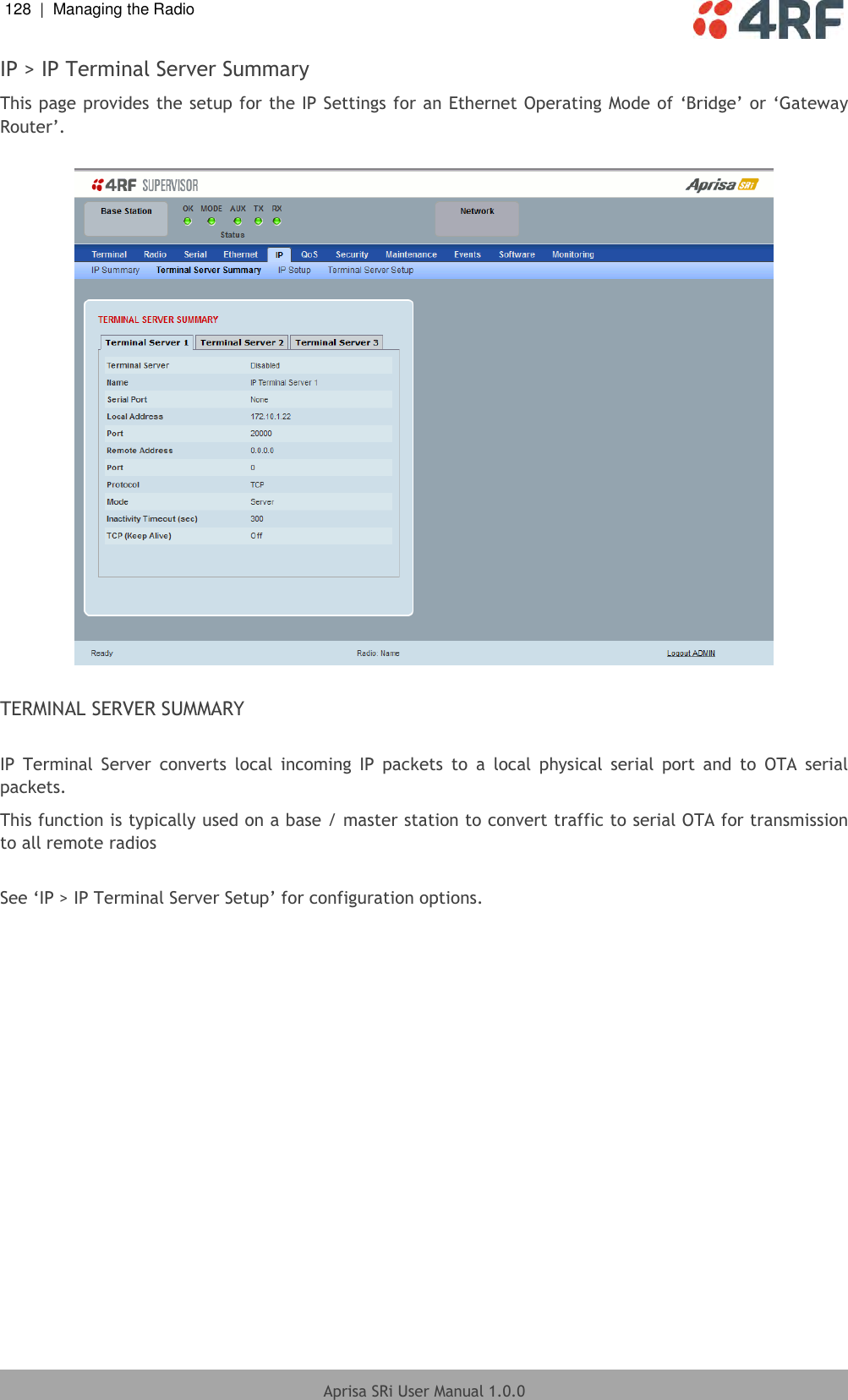
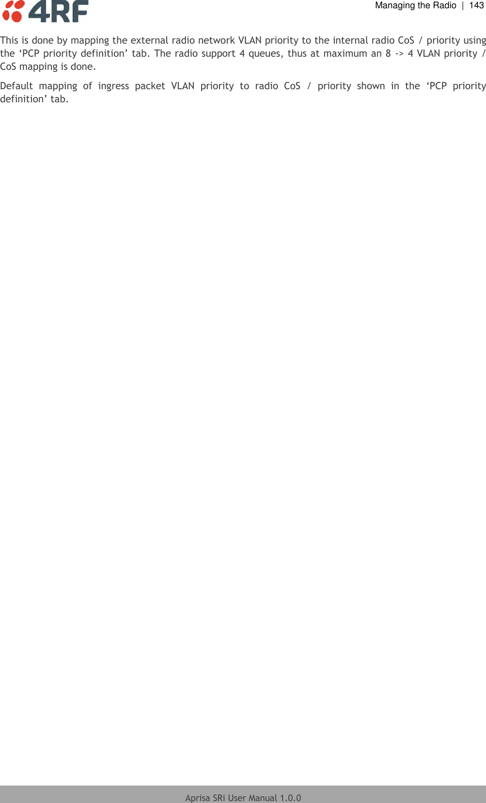
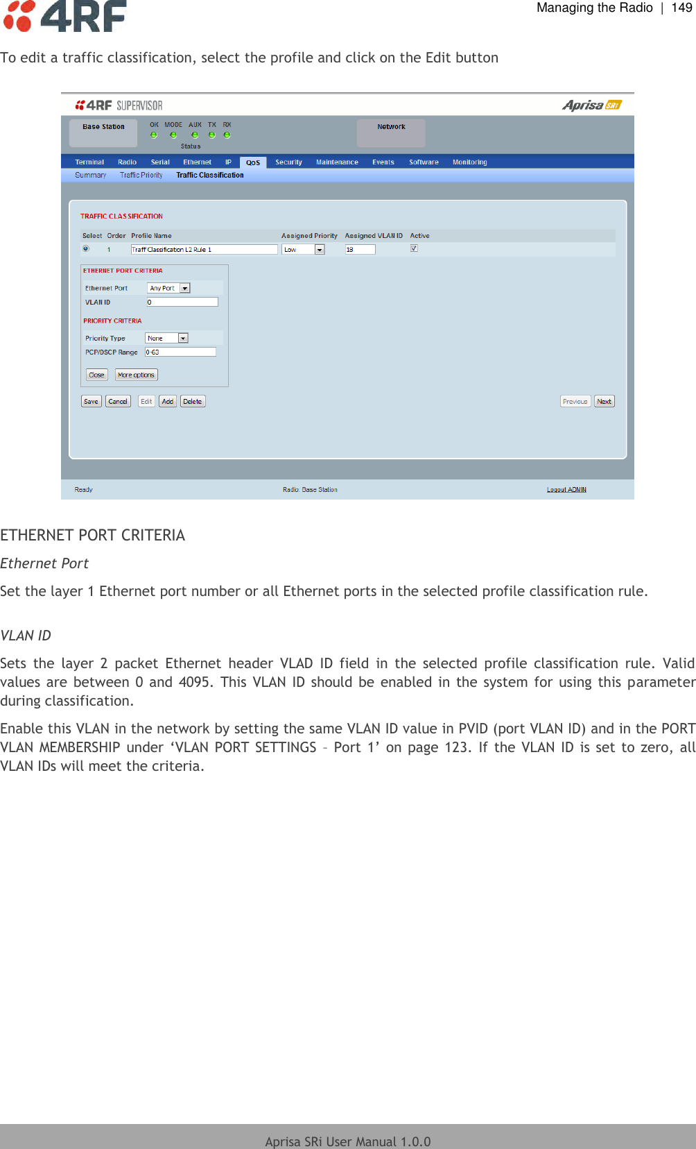
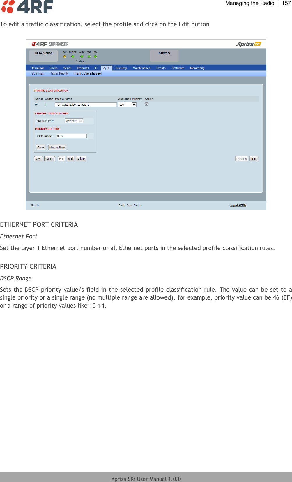
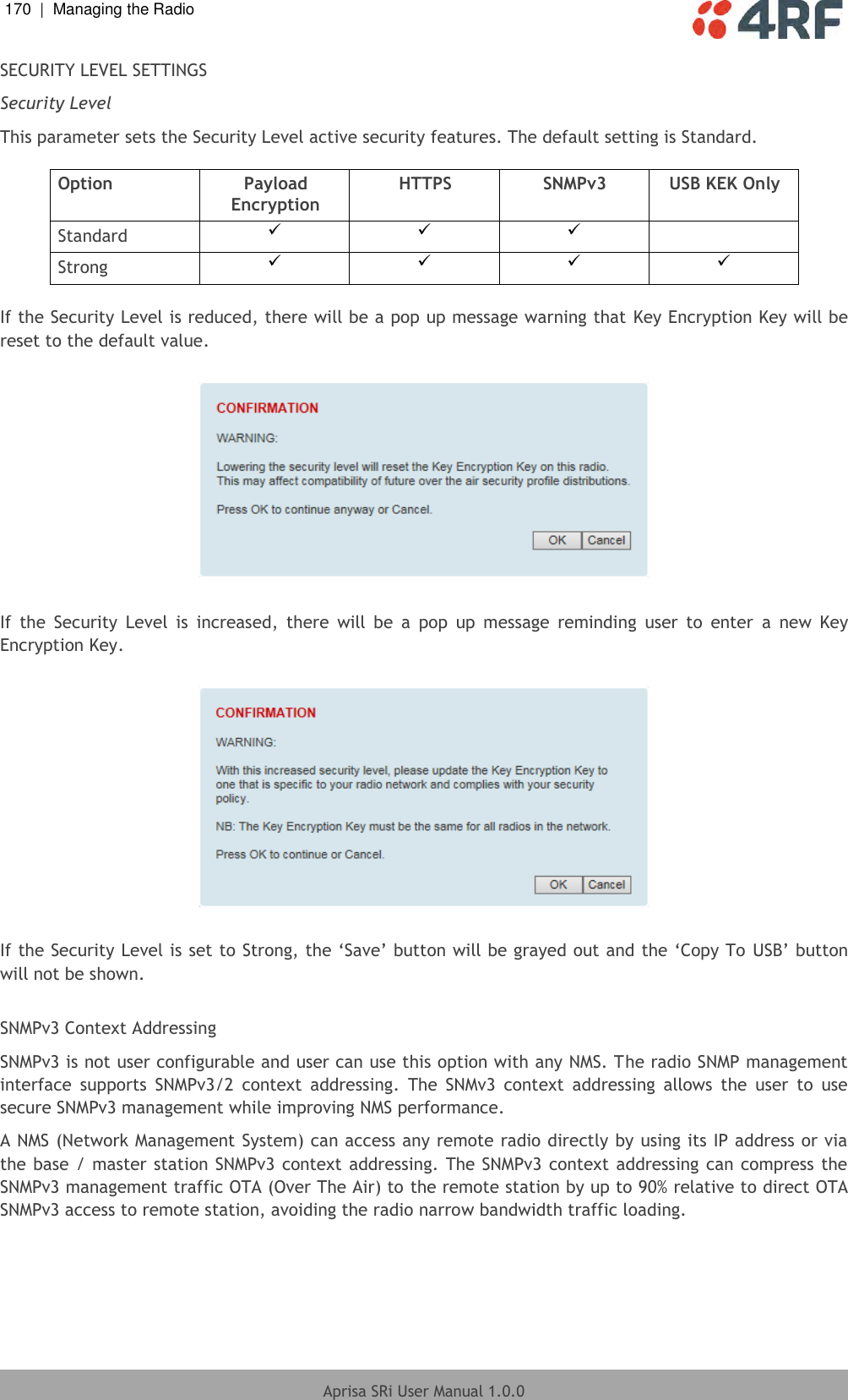
![256 | Managing the Radio Aprisa SRi User Manual 1.0.0 CLI Commands To enter a CLI command: 1. Type the first few characters of the command and hit Tab. This auto completes the command. 2. Enter the command string and enter. Note: All CLI commands are case sensitive. The top level CLI command list is displayed by typing a ? at the command prompt. The following is a list of the top level CLI commands and their usage: CLI Command Usage adduser adduser [-g <password aging>] [-a <account aging>] [-i <role>] <userName> <userPassword> browser browser <state(STR)> cd cd <changeMode(STR)> clear Clears the screen config config userdefault save restore factorydefault restore debug set subsystem param(INT) level param(INT) get clear subsystem param(INT) level param(INT) help log dump clear deleteuser deleteuser <userName> editpasswd editpasswd <oldpassword> <newpassword> edituser edituser [-p <password>] [-g <password aging>] [-a <account aging>] [-i] get get [-m <mib name>] [-n <module name>] <attribute name> [indexes] list list <tablename> logout Logs out from the CLI ls Displays the next level menu items pwd Displays the current working directory reboot Reboots the radio set set [-m <mib name> ] [-n <module name>] <attribute name> <attribute set value> [indexes] who Shows the users currently logged into the radio](https://usermanual.wiki/4RF/SI902M160/User-Guide-3092666-Page-258.png)