4RF SI902M160 900 MHz Band Frequency Hopping Radio User Manual Aprisa SRi 1 0 0
4RF Limited 900 MHz Band Frequency Hopping Radio Aprisa SRi 1 0 0
4RF >
User Manual
Standard Radio
July 2016
Version 1.0.0b

| 1
Aprisa SRi User Manual 1.0.0
Copyright
Copyright © 2016 4RF Limited. All rights reserved.
This document is protected by copyright belonging to 4RF Limited and may not be reproduced or
republished in whole or part in any form without the prior written permission of 4RF Limited.
Trademarks
Aprisa and the 4RF logo are trademarks of 4RF Limited.
Windows is a registered trademark of Microsoft Corporation in the United States and other countries. Java
and all Java-related trademarks are trademarks or registered trademarks of Sun Microsystems, Inc. in the
United States and other countries. All other marks are the property of their respective owners.
Disclaimer
Although every precaution has been taken preparing this information, 4RF Limited assumes no liability for
errors and omissions, or any damages resulting from use of this information. This document or the
equipment may change, without notice, in the interests of improving the product.
RoHS and WEEE Compliance
The Aprisa SRi is fully compliant with the European Commission’s RoHS (Restriction of Certain Hazardous
Substances in Electrical and Electronic Equipment) and WEEE (Waste Electrical and Electronic Equipment)
environmental directives.
Restriction of hazardous substances (RoHS)
The RoHS Directive prohibits the sale in the European Union of electronic equipment containing these
hazardous substances: lead, cadmium, mercury, hexavalent chromium, polybrominated biphenyls (PBBs),
and polybrominated diphenyl ethers (PBDEs).
4RF has worked with its component suppliers to ensure compliance with the RoHS Directive which came
into effect on the 1st July 2006.
End-of-life recycling programme (WEEE)
The WEEE Directive concerns the recovery, reuse, and recycling of electronic and electrical equipment.
Under the Directive, used equipment must be marked, collected separately, and disposed of properly.
4RF has instigated a programme to manage the reuse, recycling, and recovery of waste in an
environmentally safe manner using processes that comply with the WEEE Directive (EU Waste Electrical
and Electronic Equipment 2002/96/EC).
4RF invites questions from customers and partners on its environmental programmes and compliance with
the European Commission’s Directives (sales@4RF.com).

2 |
Aprisa SRi User Manual 1.0.0
Compliance General
The Aprisa SRi radio predominantly operates within frequency bands that are covered under a class license
or general user license which is a license is issued to ‘every person’.
Changes or modifications not approved by the party responsible for compliance could void the user’s
authority to operate the equipment.
Equipment authorizations sought by 4RF are based on the Aprisa SRi radio equipment being installed at a
fixed restricted access location and operated in point-to-multipoint or point-to-point mode within the
environmental profile defined by EN 300 019, Class 3.4. Operation outside these criteria may invalidate
the authorizations and / or license conditions.
The term ‘Radio’ with reference to the Aprisa SRi User Manual, is a generic term for one end station of a
point-to-multipoint Aprisa SRi network and does not confer any rights to connect to any public network or
to operate the equipment within any territory.

| 3
Aprisa SRi User Manual 1.0.0
Compliance Federal Communications Commission
The Aprisa SRi radio is designed to comply with the USA Federal Communications Commission (FCC)
specifications as follows:
Radio
47CFR part 15.247
EMC
47CFR part 15 Radio Frequency Devices
Environmental
EN 300 019, Class 3.4
Ingress Protection IP51
Safety
EN 60950-1:2006
Class 1 division 2 for hazardous locations
Frequency Band *
Channel size
Power
input
Authorization
FCC ID
902-928 MHz
50 kHz
13.8 VDC
Part 15.247
Pending
NOTE: This equipment has been tested and found to comply with the limits for a Class A digital device,
pursuant to part 15 of the FCC Rules. These limits are designed to provide reasonable protection against
harmful interference when the equipment is operated in a commercial environment. This equipment
generates, uses, and can radiate radio frequency energy and, if not installed and used in accordance with
the instruction manual, may cause harmful interference to radio communications. Operation of this
equipment in a residential area is likely to cause harmful interference in which case the user will be
required to correct the interference at his own expense.
* The Frequency Band is not an indication of the exact frequencies approved by FCC.

4 |
Aprisa SRi User Manual 1.0.0
Compliance Industry Canada
The Aprisa SRi radio is designed to comply with Industry Canada (IC) specifications as follows:
Radio
RSS-247
EMC
This Class A digital apparatus complies with Canadian
standard ICES-003.
Cet appareil numérique de la classe A est conforme à la
norme NMB-003 du Canada.
Environmental
EN 300 019, Class 3.4
Ingress Protection IP51
Safety
EN 60950-1:2006
Class 1 division 2 for hazardous locations
Frequency Band *
Channel size
Power
input
Authorization
IC
902-928 MHz
50 kHz
13.8 VDC
RSS-247
Pending
* The Frequency Band is not an indication of the exact frequencies approved by IC.
This device complies with Part 15 of the FCC Rules and Industry Canada’s licence exempt RSSs. Operation
is subject to the following two conditions: (1) This device may not cause interference; and (2) This device
must accept any interference, including interference that may cause undesired operation of the device.
Ce dispositif est conforme à la partie 15 des règles de la Federal Communications Commission (FCC) des
États Unis et d'Industrie Canada (IC) exempts de licence RSS norme(s). Son fonctionnement est assujetti
aux deux conditions suivantes: (1) Ce dispositive nedoit pas provoquer de brouillage préjudiciable, et (2) il
doit accepter tout brouillagereçu, y compris le brouillage pouvant entraîner unmauvais fonctionnement.
| 5
Aprisa SRi User Manual 1.0.0
Compliance ACMA
The Aprisa SRi radio is designed to comply with Australia ACMA specifications as follows:
Radio
Radio Communications (Short Range Devices) Standard
2004
EMC
AS/NZS 4268
Environmental
EN 300 019, Class 3.4
Ingress Protection IP51
Safety
EN 60950-1:2006
Class 1 division 2 for hazardous locations
Frequency Band *
Channel size
Power
input
Authorization
ACMA
915-928 MHz
50 kHz
13.8 VDC
Pending
Compliance RSM
The Aprisa SRi radio is designed to comply with New Zealand RSM specifications as follows:
Radio / EMC
AS/NZS 4268
Environmental
EN 300 019, Class 3.4
Ingress Protection IP51
Safety
EN 60950-1:2006
Class 1 division 2 for hazardous locations
Frequency Band *
Channel size
Power
input
Authorization
RSM
915-928 MHz
50 kHz
13.8 VDC
Licence 252286
Pending

6 |
Aprisa SRi User Manual 1.0.0
Compliance Hazardous Locations Notice
This product is suitable for use in Class 1, Division 2, Groups A - D hazardous locations or non-hazardous
locations.
The following text is printed on the Aprisa SRi fascia:
WARNING: EXPLOSION HAZARD - Do not connect or disconnect while circuits are live unless area is known
to be non-hazardous.
The following text is printed on the Aprisa SRi where the end user is in Canada:
AVERTISSEMENT: RISQUE D'EXPLOSION - Ne pas brancher ou débrancher tant que le circuit est sous
tension, à moins qu'il ne s'agisse d'un emplacement non dangereux.
The USB service ports are not to be used unless the area is known to be non-hazardous.
| 7
Aprisa SRi User Manual 1.0.0
RF Exposure Warning
WARNING:
The installer and / or user of Aprisa SRi radios shall ensure that a separation distance
as given in the following table is maintained between the main axis of the terminal’s
antenna and the body of the user or nearby persons.
Minimum separation distances given are based on the maximum values of the
following methodologies:
1. Maximum Permissible Exposure non-occupational limit (B or general public) of
47 CFR 1.1310 and the methodology of FCC’s OST/OET Bulletin number 65.
2. Reference levels as given in Annex III, European Directive on the limitation of
exposure of the general public to electromagnetic fields (0 Hz to 300 GHz)
(1999/519/EC). These distances will ensure indirect compliance with the
requirements of EN 50385:2002.
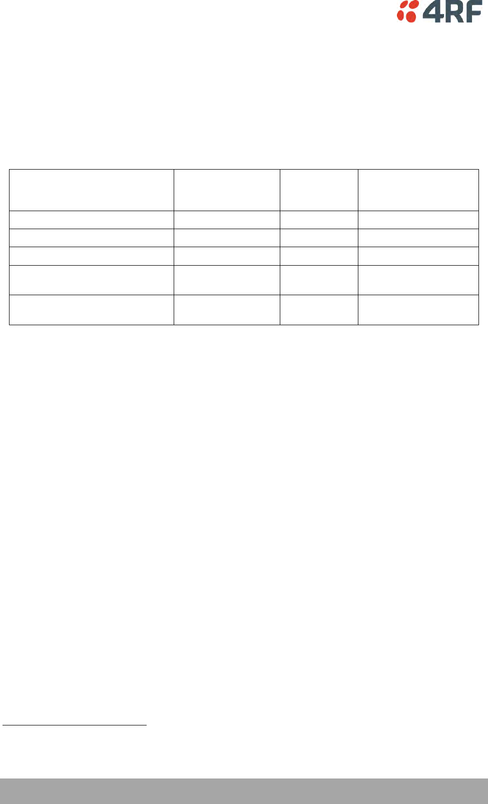
Frequency (MHz)
Maximum Power
(dBm) Note 1
Maximum Antenna
Gain (dBi)
Minimum Separation
Distance
(m)
915
+ 26
10 dBi
0.3
Note 1: The Peak Envelope Power (PEP) at maximum set power level is 1.0 W ,+30 dBm.

Contents | 9
Aprisa SRi User Manual 1.0.0
Contents
1. Getting Started ........................................................................ 13
2. Introduction ............................................................................ 15
About This Manual ............................................................................... 15
What It Covers ............................................................................ 15
Who Should Read It ...................................................................... 15
Contact Us ................................................................................. 15
What’s in the Box ............................................................................... 15
Aprisa SRi Accessory Kit ................................................................. 16
Aprisa SRi CD Contents .................................................................. 16
Software ............................................................................ 16
Documentation .................................................................... 16
3. About the Radio ....................................................................... 17
The 4RF Aprisa SRi Radio ....................................................................... 17
Product Overview ............................................................................... 18
Network Coverage and Capacity ....................................................... 18
Automatic Registration .................................................................. 18
Remote Messaging ........................................................................ 18
Product Features ................................................................................ 19
Functions .................................................................................. 19
Security .................................................................................... 20
Performance .............................................................................. 21
Usability ................................................................................... 21
System Gain vs FEC Coding ............................................................. 22
Architecture ...................................................................................... 23
Product Operation ........................................................................ 23
Physical Layer ............................................................................. 23
Data Link Layer / MAC layer ............................................................ 24
Channel Access .................................................................... 24
Hop by Hop Transmission ......................................................... 25
Adaptive Coding and Modulation ................................................ 25
Network Layer ............................................................................ 26
Packet Routing ..................................................................... 26
Static IP Router .................................................................... 27
Bridge Mode with VLAN Aware .................................................. 30
VLAN Bridge Mode Description .................................................. 31
Avoiding Narrow Band Radio Traffic Overloading .................................... 33
Interfaces ......................................................................................... 35
Antenna Interface ........................................................................ 35
Ethernet Interface ....................................................................... 35
RS-232 / RS-485 Interface ............................................................... 35
USB Interfaces ............................................................................ 35
Protect Interface ......................................................................... 35
Alarms Interface .......................................................................... 35
Front Panel Connections ....................................................................... 36
LED Display Panel ............................................................................... 37
Single Radio Software Upgrade ......................................................... 38
Network Software Upgrade ............................................................. 38
Test Mode ................................................................................. 39

10 | Contents
Aprisa SRi User Manual 1.0.0
Network Management.................................................................... 40
Hardware Alarm Inputs / Outputs ............................................................ 41
Alarm Input to SNMP Trap ............................................................... 41
Alarm Input to Alarm Output ........................................................... 41
Aprisa SR Alarm Input to Aprisa SRi Alarm Output ................................... 41
4. Implementing the Network.......................................................... 42
Network Topologies ............................................................................. 42
Point-To-Point Network .......................................................... 42
Point-to-Multipoint Network ..................................................... 42
Initial Network Deployment ................................................................... 43
Install the Base Station .................................................................. 43
Installing the Remote Stations ......................................................... 43
Network Changes ................................................................................ 44
Adding a Remote Station ................................................................ 44
5. Preparation ............................................................................ 45
Bench Setup ...................................................................................... 45
Compliance Considerations .................................................................... 46
Path Planning .................................................................................... 48
Antenna Selection and Siting ........................................................... 48
Base Station ........................................................................ 48
Remote station .................................................................... 49
Antenna Siting ..................................................................... 50
Coaxial Feeder Cables ................................................................... 51
Linking System Plan ...................................................................... 51
Site Requirements ............................................................................... 52
Power Supply .............................................................................. 52
Equipment Cooling ....................................................................... 52
Earthing and Lightning Protection ..................................................... 53
Feeder Earthing .................................................................... 53
Radio Earthing ..................................................................... 53
6. Installing the Radio ................................................................... 54
Mounting .......................................................................................... 54
Required Tools ............................................................................ 54
DIN Rail Mounting ........................................................................ 55
Rack Shelf Mounting ..................................................................... 56
Wall Mounting ............................................................................. 57
Installing the Antenna and Feeder Cable .................................................... 58
Connecting the Power Supply ................................................................. 59
External Power Supplies ................................................................. 59
Spare Fuses ................................................................................ 60
Additional Spare Fuses ............................................................ 61

Contents | 11
Aprisa SRi User Manual 1.0.0
7. Managing the Radio ................................................................... 63
SuperVisor ........................................................................................ 63
PC Requirements for SuperVisor ....................................................... 64
Connecting to SuperVisor ............................................................... 65
Management PC Connection ..................................................... 66
PC Settings for SuperVisor ....................................................... 67
Login to SuperVisor................................................................ 71
Logout of SuperVisor .............................................................. 72
SuperVisor Page Layout ........................................................... 73
SuperVisor Menu ................................................................... 75
SuperVisor Menu Access .......................................................... 76
Standard Radio............................................................................ 78
Terminal ............................................................................ 78
Radio ................................................................................ 89
Serial .............................................................................. 106
Ethernet .......................................................................... 116
IP................................................................................... 126
QoS ................................................................................ 139
Security ........................................................................... 161
Maintenance ..................................................................... 183
Events ............................................................................. 197
Software .......................................................................... 208
Monitoring ........................................................................ 227
Network Status .................................................................. 246
Command Line Interface .............................................................. 253
Connecting to the Management Port ................................................ 253
CLI Commands .......................................................................... 256
Viewing the CLI Terminal Summary ........................................... 257
Changing the Radio IP Address with the CLI ................................. 257
8. In-Service Commissioning .......................................................... 258
Before You Start ............................................................................... 258
What You Will Need .................................................................... 258
Antenna Alignment ............................................................................ 259
Aligning the Antennas ................................................................. 259
9. Product Options ...................................................................... 260
Country Specific Products .................................................................... 260
USB Serial Ports ................................................................................ 261
USB RS-232 / RS-485 Serial Port ...................................................... 261
USB RS-232 / RS-485 operation ....................................................... 261
USB RS-232 Cabling Options ........................................................... 262
USB RS-485 Cabling Options ........................................................... 262
USB Retention Clip .............................................................. 263
10. Maintenance .......................................................................... 265
No User-Serviceable Components ........................................................... 265
Software Upgrade ............................................................................. 266
Network Software Upgrade ........................................................... 266
Single Radio Software Upgrade ....................................................... 268
File Transfer Method ............................................................ 268
USB Boot Upgrade Method ..................................................... 269
Software Downgrade ............................................................ 269

12 | Contents
Aprisa SRi User Manual 1.0.0
11. Interface Connections ............................................................... 270
RJ45 Connector Pin Assignments ............................................................ 270
Ethernet Interface Connections ............................................................. 270
RS-232 Serial Interface Connections ........................................................ 271
RS-232 Pinout .................................................................... 271
RS-232 Customer Cable Wiring ................................................ 271
RS-232 RJ45 LED Indicators .................................................... 271
Alarm Interface Connections ................................................................ 272
12. Alarm Types and Sources ........................................................... 273
Alarm Types .................................................................................... 273
Alarm Events ............................................................................ 274
Informational Events ................................................................... 278
13. Specifications ......................................................................... 279
RF Specifications .............................................................................. 279
Frequency Bands ....................................................................... 279
Channel Sizes ........................................................................... 279
Receiver ................................................................................. 280
Transmitter ............................................................................. 282
Spread Spectrum ....................................................................... 282
Modem ................................................................................... 283
Data Payload Security ................................................................. 283
Interface Specifications ...................................................................... 284
Ethernet Interface ..................................................................... 284
RS-232 Asynchronous Interface ....................................................... 285
Hardware Alarms Interface ........................................................... 286
Power Specifications .......................................................................... 287
Power Supply ............................................................................ 287
Power Consumption .................................................................... 287
Power Dissipation ...................................................................... 287
General Specifications ........................................................................ 288
Environmental .......................................................................... 288
Mechanical .............................................................................. 288
Compliance .............................................................................. 289
14. Product End Of Life .................................................................. 290
End-of-Life Recycling Programme (WEEE) ................................................. 290
The WEEE Symbol Explained .......................................................... 290
WEEE Must Be Collected Separately ................................................. 290
YOUR ROLE in the Recovery of WEEE ................................................ 290
EEE Waste Impacts the Environment and Health .................................. 290
15. Copyrights ............................................................................. 291
16. Abbreviations ......................................................................... 293
17. Index ................................................................................... 294

Getting Started | 13
Aprisa SRi User Manual 1.0.0
1. Getting Started
This section is an overview of the steps required to commission an Aprisa SRi radio network in the field:
Phase 1:
Pre-installation
1.
Confirm path planning.
Page 48
2.
Ensure that the site preparation is complete:
Power requirements
Tower requirements
Environmental considerations, for example, temperature control
Mounting space
Page 51
Phase 2:
Installing the radios
1.
Mount the radio.
Page 54
2.
Connect earthing to the radio.
Page 53
3.
Confirm that the:
Antenna is mounted and visually aligned
Feeder cable is connected to the antenna
Feeder connections are tightened to recommended level
Tower earthing is complete
4.
Install lightning protection.
Page 53
5.
Connect the coaxial jumper cable between the lightning protection and the
radio antenna port.
Page 58
6.
Connect the power to the radio.
Page 59

14 | Getting Started
Aprisa SRi User Manual 1.0.0
Phase 3:
Establishing the link
1.
If radio’s IP address is not the default IP address (169.254.50.10 with a subnet
mask of 255.255.0.0) and you don’t know the radio’s IP address see ‘Command
Line Interface’ on page 253.
Page 253
2.
Connect the Ethernet cable between the radio’s Ethernet port and the PC.
3.
Confirm that the PC IP settings are correct for the Ethernet connection:
IP address
Subnet mask
Gateway IP address
Page 67
4.
Open a web browser and login to the radio.
Page 71
5.
Set or confirm the RF characteristics:
TX / RX frequency
TX output power
Zone / channel selection
Page 101
6.
Compare the actual RSSI to the expected RSSI value (from your path planning).
Page 235
7.
Align the antennas.
Page 259
8.
Confirm that the radio is operating correctly; the OK, MODE and AUX LEDs are
green.

Introduction | 15
Aprisa SRi User Manual 1.0.0
2. Introduction
About This Manual
What It Covers
This user manual describes how to install and configure an Aprisa SRi point-to-multipoint digital radio
network.
It specifically documents an Aprisa SRi radio running system software version 1.0.0 .
It is recommended that you read the relevant sections of this manual before installing or operating the
radios.
Who Should Read It
This manual has been written for professional field technicians and engineers who have an appropriate
level of training and experience.
Contact Us
If you experience any difficulty installing or using Aprisa SRi after reading this manual, please contact
Customer Support or your local 4RF representative.
Our area representative contact details are available from our website:
4RF Limited
26 Glover Street, Ngauranga
PO Box 13-506
Wellington 6032
New Zealand
E-mail
support@4rf.com
Web site
www.4rf.com
Telephone
+64 4 499 6000
Facsimile
+64 4 473 4447
Attention
Customer Services
What’s in the Box
Inside the box you will find:
One Aprisa SRi radio fitted with a power connector.
One Aprisa SRi Accessory kit containing the following:
Aprisa SRi CD
Aprisa SRi Quick Start Guide
Management Cable
16 | Introduction
Aprisa SRi User Manual 1.0.0
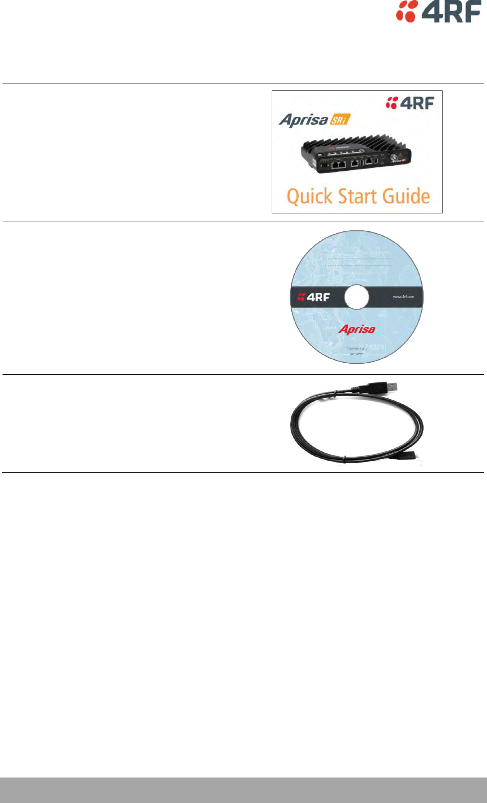
Aprisa SRi Accessory Kit
The accessory kit contains the following items:
Aprisa SRi Quick Start Guide
Aprisa SRi CD
Management Cable
USB Cable USB A to USB micro B, 1m
Aprisa SRi CD Contents
The Aprisa SRi CD contains the following:
Software
The latest version of the radio software (see ‘Software Upgrade’ on page 266)
USB Serial Driver
Web browsers - Mozilla Firefox and Internet Explorer are included for your convenience
Adobe™ Acrobat® Reader® which you need to view the PDF files on the Aprisa SRi CD
Documentation
User manual - an electronic (PDF) version for you to view online or print
Product collateral - application overviews, product description, quick start guide, case studies,
software release notes and technical papers
About the Radio | 17
Aprisa SRi User Manual 1.0.0
3. About the Radio
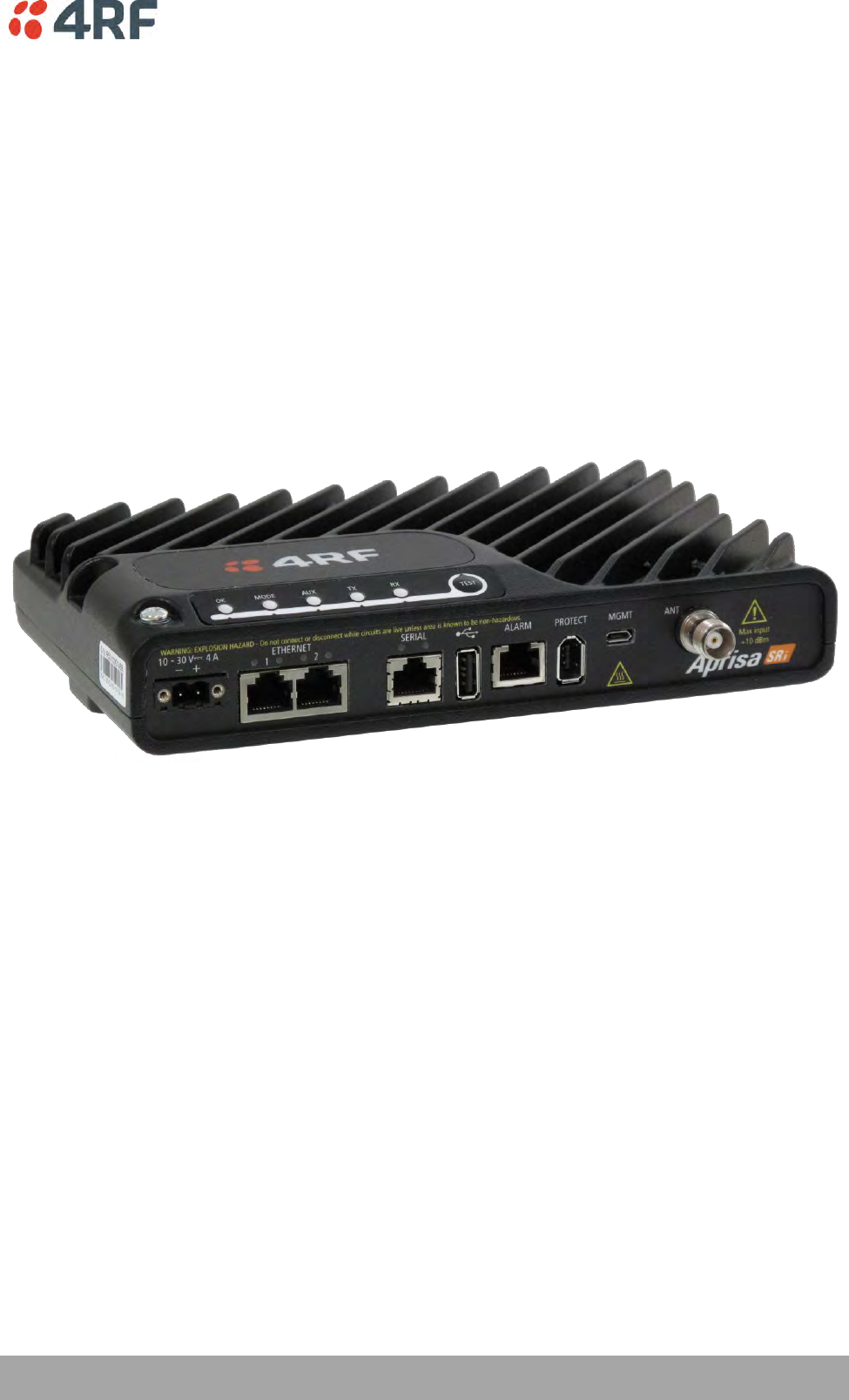
The 4RF Aprisa SRi Radio
The 4RF Aprisa SRi is a Point-To-Multipoint (PMP) digital radio providing 915 MHz Industrial Licence Free
Spread Spectrum communications.
The radios carry a combination of serial data and Ethernet data between the base station and remote
stations.
A single Aprisa SRi is configurable as a Point-To-Multipoint base station or remote station.

18 | About the Radio
Aprisa SRi User Manual 1.0.0
Product Overview
Network Coverage and Capacity
The Aprisa SRi has a typical link range of up to 50 km, however, geographic features, such as hills,
mountains, trees and foliage, or other path obstructions, such as buildings, will limit radio coverage.
Additionally, geography may reduce network capacity at the edge of the network where errors may occur
and require retransmission. However, the Aprisa SRi uses 0.4 W (+26 dBm) output power and Forward Error
Correction (FEC) which greatly improves the sensitivity and system gain performance of the radio resulting
in less retries and minimal reduction in capacity.
Ultimately, the overall performance of any specific network will be defined by a range of factors including
the RF output power, the modulation used and its related receiver sensitivity, the geographic location,
the number of remote stations in the base station coverage area and the traffic profile across the
network. Effective network design will distribute the total number of remote stations across the available
base stations to ensure optimal geographic coverage and network capacity.
One base station can register and operate with up to 500 remote stations.
The practical limit of remote stations that can operate with one base station is determined by a range of
factors including the number of services, the packet sizes, the protocols used, the message types and
network timeouts.
Automatic Registration
On start-up, the remote station listens for the base station before attempting registration. It then
transmits a registration message to the base station which responds with a registration response. The base
station records the details of all the remote stations active in the network.
If a remote station cannot register with the base station after multiple attempts within 10 minutes, it will
automatically reboot. If remote is not able to register with base station in 5 attempts, then a ‘Network
Configuration Warning’ alarm event will be raised indicating that a remote is not registered with the base
station.
If a remote station has registered with the base station but then loses communication, it will
automatically reboot within 2 minutes.
Remote Messaging
There are two message types in the Aprisa SRi network, broadcast messages and unicast messages.
Broadcast messages are transmitted by the base station to the remote stations and unicast messages are
transmitted by the remote station to the base station. These messages are commonly referred to as uplink
(unicast remote to base) and downlink (broadcast base to remote).
All remotes within the coverage area will receive broadcast messages and pass them on to either the
Ethernet or serial interface. The RTU determines if the message is intended for it and will accept it or
discard it.

About the Radio | 19
Aprisa SRi User Manual 1.0.0
Product Features
Functions
Point-to-Multipoint (PMP) operation
Unlicensed frequency bands in the frequency range of 902-928 MHz as permitted by the local
regulator
Channel size of 50 kHz
Half duplex RF Point-To-Multipoint operation
Military style jam resistant frequency hopping spread spectrum technology operating where other
licence free radios have difficulty in break through
Full band and reduced non-overlapping zone options allow a tailored approach to interference
management for maximum range
Ethernet data interface and RS-232 / RS-485 asynchronous
Data encryption and authentication using 128,192 and 256 bit AES and CCM security standards
Terminal server operation for transporting RS-232 / RS-485 traffic over IP or Ethernet and
converting IP packets to a local physical serial port
SLIP support for RS-232
IEEE 802.1Q VLAN support with single and double VLAN tagged and add/remove VLAN manipulation
to adapt to the appropriate RTU / PLCs
QoS supports using IEEE 802.1p VLAN priority bits to prioritize and handle the VLAN / traffic types
QoS per port (Ethernet, serial, management)
L2 / L3 / L4 filtering for security and avoiding narrow band radio network overload
L3 Gateway Router mode with standard static IP route for simple routing network integration
L3 Router mode with per Ethernet interface IP address and subnet
L2 Bridge mode with VLAN aware for standard Industrial LAN integration
Ethernet and serial payload compression to increase the narrow band radio capacity
SuperVisor web management support for element and sub-network management
SNMPv1/2/3 & encryption MIB supports for 4RF SNMP manager or third party SNMP agent network
management
SNMP context addressing for compressed SNMP access to remote stations
SNTP for accurate wide radio network time and date
RADIUS security for remote user authorization, authentication and accounting
Transparent to all common SCADA protocols; e.g. Modbus, IEC 60870-5-101/104, DNP3 or similar
Complies with international standards, including FCC, EMC, safety and environmental standards

20 | About the Radio
Aprisa SRi User Manual 1.0.0
Security
The Aprisa SRi provides security features to implement the key recommendations for industrial control
systems. The security provided builds upon the best in class from multiple standards bodies, including:
IEC/TR 62443 (TC65) ‘Industrial Communications Networks – Network and System Security’
IEC/TS 62351 (TC57) ‘Power System Control and Associated Communications – Data and
Communication Security’
FIPS PUB 197, NIST SP 800-38C, IETF RFC3394, RFC3610 and IEEE P1711/P1689/P1685
FIPS 140-2: Security Requirements for Cryptographic Modules
The security features implemented are:
Data encryption
Counter Mode Encryption (CTR) using Advanced Encryption Standard (AES) 128, 192, 256 bit,
based on FIPS PUB 197 AES encryption (using Rijndael version 3.0)
Data authentication
NIST SP 800-38C Cipher Block Chaining Message Authentication Code (CBC-MAC) based on RFC
3610 using Advanced Encryption Standard (AES)
Data payload security
CCM Counter with CBC-MAC integrity (NIST special publication 800-38C)
Secured management interface protects configuration
L2 / L3 / L4 Address filtering enables traffic source authorization
Proprietary physical layer protocol and modified MAC layer protocol based on standardized IEEE
802.15.4
SNMPv3 with Encryption for NMS secure access
Secure USB software upgrade
Key Encryption Key (KEK) based on RFC 3394, for secure Over The Air Re-keying (OTAR) of
encryption keys
User privilege allows the accessibility control of the different radio network users and the user
permissions

About the Radio | 21
Aprisa SRi User Manual 1.0.0
Performance
Typical deployment of 30 remote stations from one base station with a practical limit of a few
hundred remote stations
Low noise receiver
Forward Error Correction
Electronic tuning over the frequency band
Thermal management for high power over a wide temperature range
Usability
Configuration / diagnostics via front panel Management Port USB interface, Ethernet interface
Built-in webserver SuperVisor with full configuration, diagnostics and monitoring functionality,
including remote station configuration / diagnostics over the radio link
LED display for on-site diagnostics
Dedicated alarm port
Software upgrade and diagnostic reporting via the host port USB flash drive
Over-the-air software distribution and upgrades
Simple installation with integrated mounting holes for wall, DIN rail and rack shelf mounting

22 | About the Radio
Aprisa SRi User Manual 1.0.0
System Gain vs FEC Coding
Minimum FEC coding results in lower system gain, lower coverage but higher capacity.
This table defines the modulation order based on gross capacity:
Modulation
FEC Coding
Capacity
QPSK (Low Gain)
Min Coded FEC
Minimum
16QAM (Low Gain)
Min Coded FEC
64QAM (Low Gain)
Min Coded FEC
Maximum
This table defines the modulation order based on receiver sensitivity:
Modulation
FEC Coding
Coverage
QPSK (Low Gain)
Min Coded FEC
Maximum
16QAM (Low Gain)
Min Coded FEC
64QAM (Low Gain)
Min Coded FEC
Minimum

About the Radio | 23
Aprisa SRi User Manual 1.0.0
Architecture
The Aprisa SRi Architecture is based around a layered TCP/IP protocol stack:
Physical
Proprietary wireless
RS-232 and Ethernet interfaces
Link
Proprietary wireless (channel access, ARQ, segmentation)
VLAN aware Ethernet bridge
Network
Standard IP
Proprietary automatic radio routing table population algorithm
Transport
TCP, UDP
Application
HTTPS web management access through base station with proprietary management application
software including management of remote stations over the radio link
SNMPv1/2/3 for network management application software
Product Operation
There are three components to the wireless interface: the Physical Layer (PHY), the Data Link Layer (DLL)
and the Network Layer. These three layers are required to transport data across the wireless channel in
the Point-to-Multipoint (PMP) configuration. The Aprisa SRi DLL is largely based on the 802.15.4 Media
Access Control (MAC) layer using a proprietary implementation.
Physical Layer
The Aprisa SRi PHY uses a one frequency half duplex transmission mode which eliminates the need for a
duplexer.
Remote nodes are predominantly in receive mode with only sporadic bursts of transmit data. This reduces
power consumption.
The Aprisa SRi is a packet based radio. Data is sent over the wireless channel in discrete packets / frames,
separated in time. The PHY demodulates data within these packets with coherent detection.
The Aprisa SRi PHY provides carrier, symbol and frame synchronization predominantly through the use of
preambles. This preamble prefixes all packets sent over the wireless channel which enables fast
Synchronization.

24 | About the Radio
Aprisa SRi User Manual 1.0.0
Data Link Layer / MAC layer
The Aprisa SRi PHY enables multiple users to be able to share a single wireless channel; however a DLL is
required to manage data transport. The two key components to the DLL are channel access and hop by
hop transmission.
Channel Access
The Aprisa SRi radio uses a channel access of Access Request. Channel access scheme where the base
stations controls the communication on the channel. Remotes ask for access to the channel, and the base
station grants access if the channel is not occupied.
Access Request
This scheme is particularly suited to digital SCADA systems where all data flows through the base station.
In this case it is important that the base station has contention-free access as it is involved in every
transaction. The channel access scheme assigns the base station as the channel access arbitrator and
therefore inherently it has contention-free access to the channel. This means that there is no possibility
of contention on data originating from the base station. As all data flows to or from the base station, this
significantly improves the robustness of the system.
All data messages are controlled via the AG (access grant) control message and therefore there is no
possibility of contention on the actual end user data. If a remote station accesses the channel, the only
contention risk is on the AR (access request) control message. These control messages are designed to be
as short as possible and therefore the risk of collision of these control messages is significantly reduced.
Should collisions occur these are resolved using a random back off and retry mechanism.
As the base station controls all data transactions multiple applications can be effectively handled,
including a mixture of polling and report by exception.
About the Radio | 25
Aprisa SRi User Manual 1.0.0
Hop by Hop Transmission
Hop by Hop Transmission is realized in the Aprisa SRi by adding a MAC address header to the packet. For
802.15.4, there are 2 addresses, the source and destination addresses.
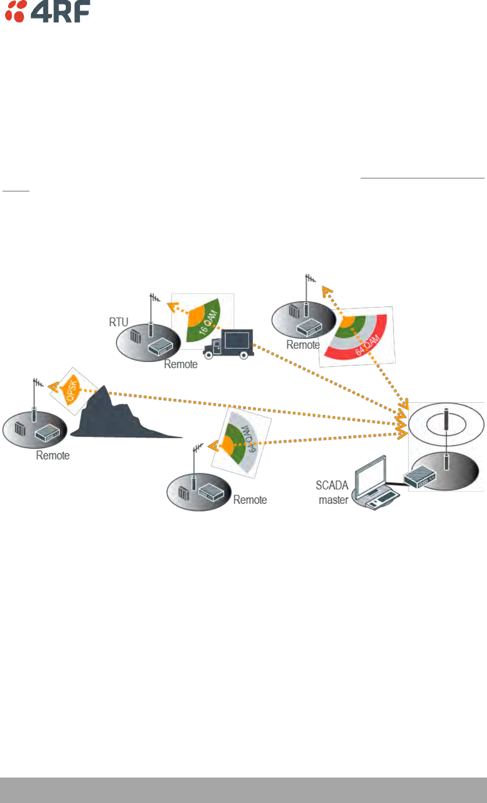
Adaptive Coding and Modulation
The Aprisa SRi provides Adaptive Coding and Modulation (ACM) which maximizes the use of the RF path to
provide the highest radio capacity available.
ACM automatically adjusts the modulation coding and FEC code rate in the remote to base direction of
transmission over the defined modulation range based on the signal quality for each individual remote
radio.
When the RF path is healthy (no fading), modulation coding is increased and the FEC code rate is
decreased to maximize the data capacity.
If the RF path quality degrades, modulation coding is decreased and the FEC code rate is increased for
maximum robustness to maintain path connectivity.
26 | About the Radio
Aprisa SRi User Manual 1.0.0
Network Layer
Packet Routing
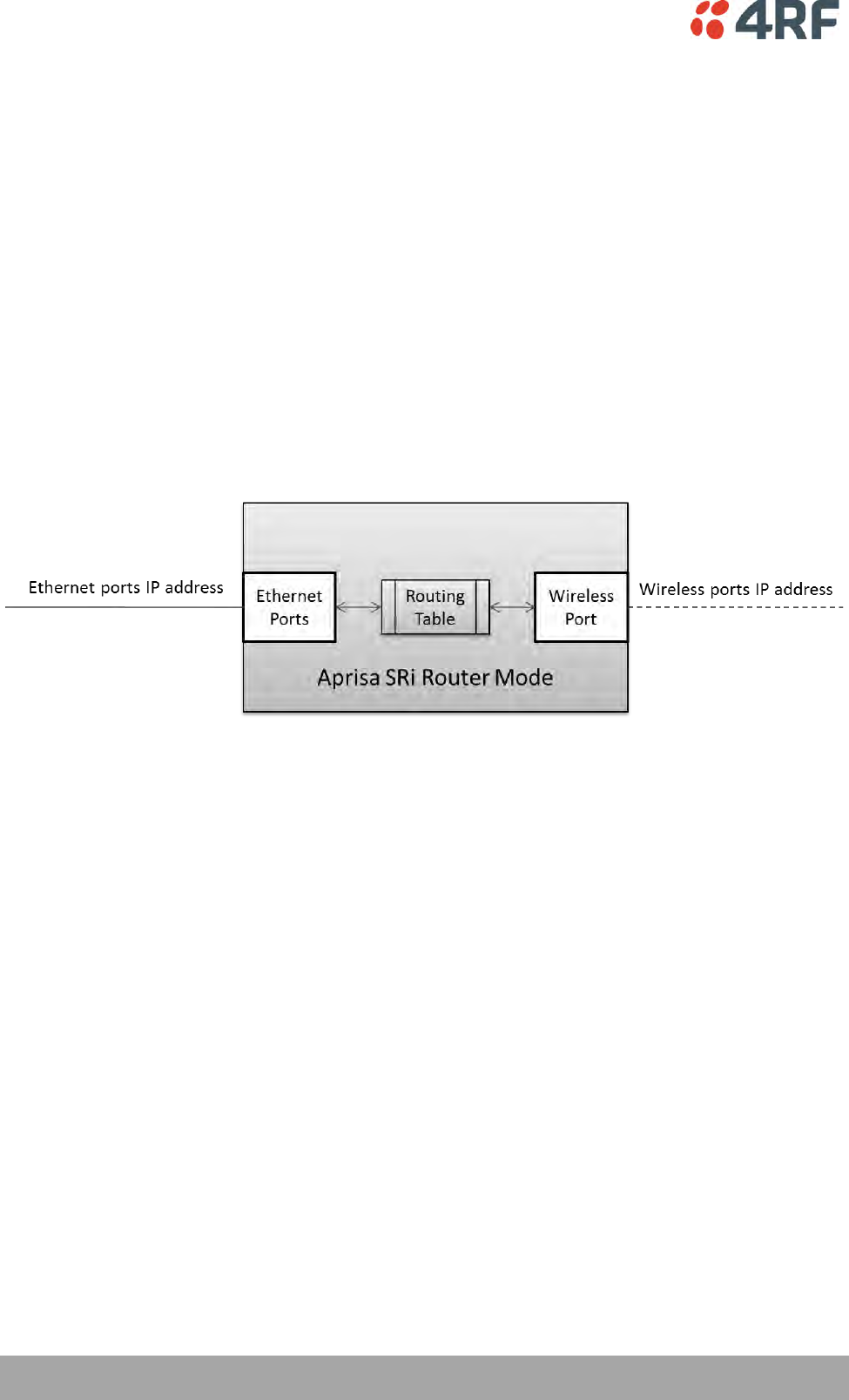
Aprisa SRi is a standard static IP router which routes and forwards IP packet based on standard IP address
and routing table decisions.
Aprisa SRi router mode (see figure below), enables the routing of IP packets within the Aprisa SRi wireless
network and in and out to the external router / IP RTUs devices connected to the Aprisa SRi wired
Ethernet ports.
Within the Aprisa SRi Router mode, each incoming Ethernet packet on the Ethernet port is stripped from
its Ethernet header to reveal the IP packet and to route the IP packet based on its routing table. If the
destination IP address is one of the RTUs, the packet is then forwarded to the wireless ports and
broadcasted as a PMP wireless packet to all the remote stations. The appropriate remote then routes the
IP packet and forwards it based on its routing table to the appropriate Ethernet port, encapsulating the
appropriate next hop MAC header and forwarding it to the RTU. The RTU can then interpret and process
the IP data and communication is established between the RTU and the initiating communication device.
About the Radio | 27
Aprisa SRi User Manual 1.0.0
Static IP Router
The Aprisa SRi works in the point-to-multipoint (PMP) network as a standard static IP router with the
Ethernet and wireless / radio as interfaces and serial ports using terminal server as a virtual interface.
The Aprisa SRi static router is semi-automated operation, where the routing table is automatically created
in the base station and populated with routes to all remote stations in the network during the registration
process and vice versa, where the routing table is automatically created in remote stations and populated
with routes to base station during the registration process. Updates occur when remote is disconnected
from network for any reason, with the routing table updated in a controlled fashion.
Also, in decommission operation, the base station routing tables are completely flushed allowing an
automatic rebuild. This avoids the user manually inserting / removing of multiple static routes to build /
change the routes in the network which might be tedious and introduce significant human error. The
Aprisa SRi works as a static IP router without using any routing protocol and therefore does not have the
overhead of a routing protocol for better utilization of the narrow bandwidth network.
In addition to the semi-automated routes, the user can manually add / remove routes in the routing table
for the radio interface, Ethernet Interface and for routers which are connected to the radio network.
The Aprisa SRi base station is used as a gateway to other networks. Thus, a configurable IP address default
gateway can be set using a static route in the routing table with a destination IP address of the
destination network address. It is recommended to use a real network IP address (actual device IP) for the
gateway and not 0.0.0.0.
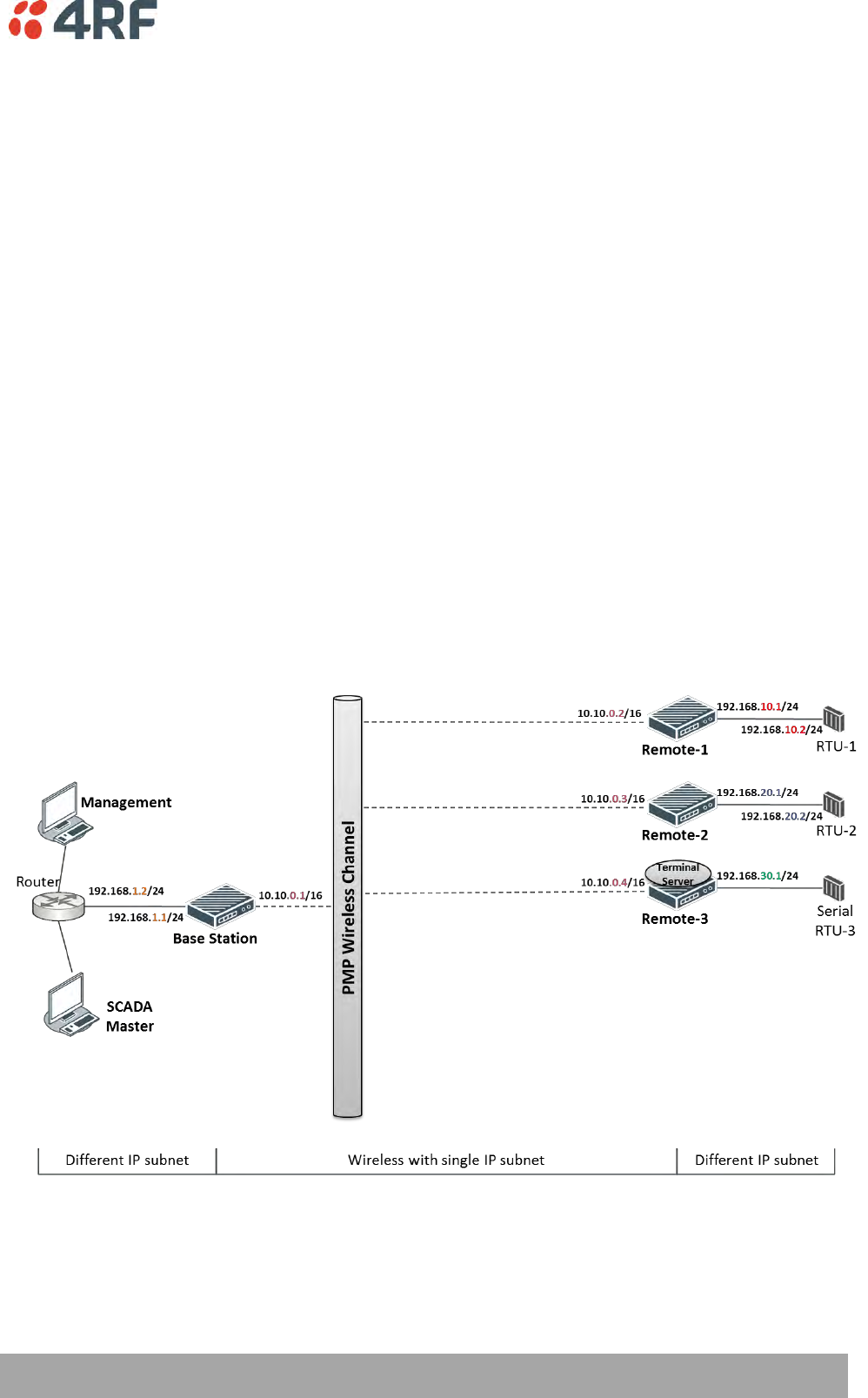
The Aprisa SRi sub-netting rules distinguish between the wireless interface and the remote Ethernet
interface where RTUs are connected. The entire wireless network is set on a single IP subnet, while each
Aprisa SRi remote’s Ethernet interface is set to a different subnet network. In this way, the user can easily
distinguish between the remotes subnet IP addresses.
28 | About the Radio
Aprisa SRi User Manual 1.0.0
The Radio Network as a Gateway Router
The Aprisa SRi point-to-multipoint radio network can be considered as a gateway router where the
‘network Ethernet interface’ on each radio in the network is the ‘router port’.
The routing table for all directly attached devices to the Aprisa SRi network, at the Base or the Remote
stations is automatically built and no static routes are required to be entered for those device routes.
The ‘Radio interface IP address’ is used internally for the radio network and automatic routes. It is not
used when setting static routes or default gateways.
Static route IP addresses or the default gateway should use the ‘network Ethernet interface’ IP address.
External network routers should be set with a high metric for the SRi path, to prevent route updates being
sent over the radio network.
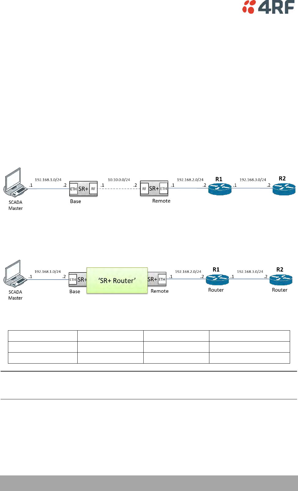
The Radio Network as a Router – Example
The purpose of this example is to determine the static route setting for router R2 in the base station and
remote station in the following network.
Since the Aprisa SRi network should be considered as a router where the network Ethernet interface is the
‘router port’, the network configuration for setting the static routes or the default gateway IP addresses is
described in the follow figure:
Thus, the static route setting for router R2 at the Aprisa SRi base station and remote station will be:
Destination Address
Destination Mask
Gateway Address
Static Route Setting at ?
192.168.3.0
255.255.255.0
192.168.2.1
Base station
192.168.3.0
255.255.255.0
192.168.2.2
Remote station
Note: The radio network (base station and remote stations) will automatically build routes to the attached
device e.g. SCADA Master station or attached router e.g. router R1 so static routes are not required for
these devices.

About the Radio | 29
Aprisa SRi User Manual 1.0.0
Static IP Router – Human Error Free
To ensure correct operation, the Aprisa SR router base station alerts when one (or more) of the devices is
not configured for router mode or a duplicated IP is detected when manually added.
When the user changes the base station IP address / subnet, the base station sends an ARP unsolicited
announcement message and the remote stations auto-update their routing table accordingly. This also
allows the router that is connected to the base station to update its next hop IP address and its routing
table.
When the user changes the remote station IP address / subnet, a re-registration process in the base
station then auto-updates its routing table accordingly.
Terminal Server - Transition to Converged Ethernet / IP Network
Customers that are transitioning their SCADA network to an Ethernet / IP SCADA network, can
simultaneously operate their legacy serial RTUs, not as a separate serial network to the new Ethernet / IP
network, but as part of the Ethernet / IP network, by using the terminal server feature.
The Aprisa SR terminal server is an application running in the radio that encapsulates serial traffic into
Ethernet / IP traffic. For SCADA networks, this enables the use of both serial and Ethernet / IP RTUs
within an Ethernet / IP based SCADA network.
30 | About the Radio
Aprisa SRi User Manual 1.0.0
Bridge Mode with VLAN Aware
Ethernet VLAN Bridge / Switch Overview
The Aprisa SRi in Bridge mode of operation is a standard Ethernet Bridge based on IEEE 802.1d or VLAN
Bridge based on IEEE 802.1q/p which forward / switch Ethernet packet based on standard MAC addresses
and VLANs using FDB (forwarding database) table decisions. VLAN is short for Virtual LAN and is a virtual
separate network, within its own broadcast domain, but across the same physical network.
VLANs offer several important benefits such as improved network performance, increased security and
simplified network management.
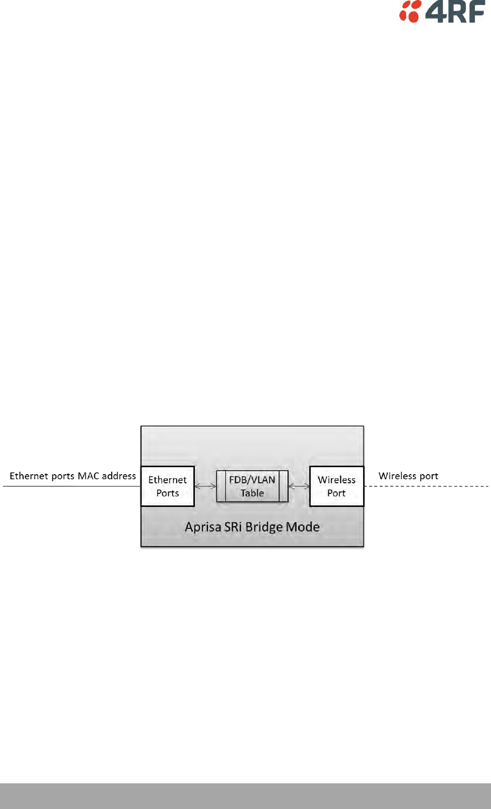
The Aprisa SRi Bridge mode (see figure below), is the default mode of operation and it enables the
switching / bridging of Ethernet VLAN tagged or untagged packets within the Aprisa SRi wireless network
and in and out to the external Industrial LAN network and RTUs devices connected to the Aprisa SRi wired
Ethernet ports or serial ports through the terminal server function.
Within the Aprisa SRi Bridge mode, each incoming Ethernet packet is inspected for the destination MAC
address (and VLAN) and looks up its FDB table for information on where to send the specific Ethernet
frame. If the FDB table doesn’t contain the specific MAC address, it will flood the Ethernet frame out to
all ports in the broadcast domain and when using VLAN, the broadcast domain is narrowed to the specific
VLAN used in the packet (i.e. broadcast will be done only to the ports which configured with that specific
VLAN).
The FDB table is used to store the MAC addresses that have been learnt and the ports associated with that
MAC address. If the destination MAC address is one of the RTUs, the packet is then forwarded to the
wireless ports and broadcast as a PMP wireless packet to all the remote stations. The appropriate remote
then switches the Ethernet packet and forwards it based on its FDB table (based on the MAC or VLAN &
MAC) to the appropriate Ethernet port to the RTU. The RTU can then interpret and process the Ethernet /
IP data and communication is established between the RTU and the initiating communication device.
About the Radio | 31
Aprisa SRi User Manual 1.0.0
VLAN Bridge Mode Description
General – Aprisa SRi VLAN Bridge
The Aprisa SRi works in a point-to-multipoint (PMP) network as a standard VLAN bridge with the Ethernet
and wireless / radio as interfaces and serial ports using terminal server as a virtual interface.
The Aprisa SRi is a standard IEEE 802.1q VLAN bridge, where the FDB table is created by the bridge
learning / aging process. New MACs are learnt and the FDB table updated. Unused MACs are aged out and
flushed automatically after aging period.
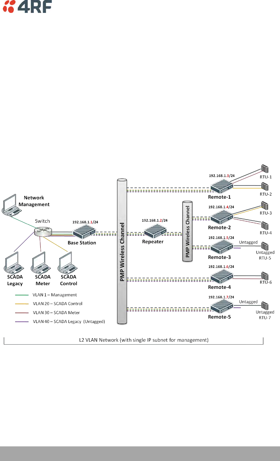
VLANs are statically configured by the user on the ports where a Virtual LAN is required across the radio
network. An example of VLAN isolation of traffic type is shown in the figure below, where RTUs #1, 4 and
6 together with SCADA meter master form a Virtual LAN which is isolated from the other devices, even
though they are on the same physical network. VLAN management can be used to manage with external
NMS all the Aprisa SRi devices on the radio network and is automatically created with a VLAN ID = 1
default value. The VLAN ID can be changed by the user later on.
Each device in the Aprisa SRi bridge is identified by its own IP address, as shown in the figure.

32 | About the Radio
Aprisa SRi User Manual 1.0.0
VLANs – Single, Double and Trunk VLAN ports
The Aprisa SRi supports single VLAN (CVLAN), double VLAN (SVLAN) and trunk VLAN.
A single VLAN can be used to segregate traffic type.
A double VLAN can be used to distinguish between Aprisa SRi sub-networks (remotes), where the outer
SVLAN is used to identify the sub-network and the CVLAN is used to identify the traffic type. In this case,
a double tagged VLAN will be forwarded across the Industrial LAN network and switched based on the
SVLAN to the appropriate Aprisa SRi sub-network. When packet enters the Aprisa SRi network, the SVLAN
will be stripped off (removed) and the forwarding will be done based on the CVLAN, so only a single VLAN
will pass through over the radio network and double VLAN will be valid on the borders of the radio
network.
Trunk VLAN is also supported by the Aprisa SRi where the user can configure multiple VLANs on a specific
Ethernet port, creating a trunk VLAN port. For example, in the above figure, a single trunk VLAN port is
created between the switch and the Aprisa SRi base station, carrying VLAN ID #1, 20, 30 and 40.
VLAN Manipulation – Add / Remove VLAN Tags
In order to support double VLAN and different device types connected to the Aprisa SRi e.g. switches,
RTUs, etc, which can be VLAN tagged or untagged / plain Ethernet devices, add / remove VLAN
manipulation is required.
In an Aprisa SRi VLAN tagged network, a remote Aprisa SRi connected to a plain RTU without VLAN
support, will remove (strip-off) the VLAN tag from the packet before sending it to the RTU. On the other
direction, when the RTU is sending an untagged packet, the Aprisa SRi will add (append) an appropriate
user pre-configure VLAN tag before sending it over the air to the base station. This is shown in the above
figure on untagged RTU #5 and 7.
QoS using VLAN
VLANs carry 3 priority bits (PCP field) in the VLAN tag allowing prioritization of VLAN tagged traffic types
with 8 levels of priority (where 7 is the highest priority and 0 is the lowest priority). The Aprisa SRi
supports QoS (Quality of Service) where the priority bits in the VLAN tagged frame are evaluated and
mapped to four priority levels and four queues supported by the Aprisa SRi radio. Packets in the queues
are then scheduled out in a strict priority fashion for transmission over-the-air as per the priority level
from high to low.

About the Radio | 33
Aprisa SRi User Manual 1.0.0
Avoiding Narrow Band Radio Traffic Overloading
The Aprisa SRi supports mechanisms to prevent narrowband radio network overload:
1. L3/L4 Filtering
The L3 filtering can be used to block undesired traffic from being transferred on the narrow band channel,
occupying the channel and risking the SCADA critical traffic. L3/4 filtering has the ability to block a known
IP address and applications using TCP/IP or UDP/IP protocols with multiple filtering rules. The L3 (/L4)
filter can block/forward (discard/process) a specific IP address and a range of IP addresses. Each IP
addressing filtering rule set can also be set to filter a L4 TCP or UDP port/s which in most cases relates to
specific applications as per IANA official and unofficial well-known ports. For example, filter and block E-
mail SMTP or TFTP protocol as undesired traffic over the SCADA network. The user can block a specific or
range of IP port addresses, examples SMTP (Simple Mail Transfer Protocol) TCP port 25 or TFTP (Simple
Trivial File Transfer Protocol) UDP port 69.
2. L2 Address Filtering
L2 Filtering (Bridge Mode) provides the ability to filter radio link traffic based on specified Layer 2 MAC
addresses. Destination MAC (DA) addresses and a Source MAC (SA) addresses and protocol type (ARP, VLAN,
IPv4, IPv6 or Any type) that meet the filtering criteria will be transmitted over the radio link. Traffic that
does not meet the filtering criteria will not be transmitted over the radio link.
3. L2 Port VLANs Ingress Filtering and QoS
Double VLAN (Bridge Mode)
Double VLAN is used to distinguish/segregate between different radio sub-networks (remotes). Traffic
with double VLANs which are not destined to a specific sub-network will be discarded on the ingress of the
radio sub-network, avoiding the overload of the radio sub-network.
Single VLAN (Bridge Mode)
Single VLAN is used to distinguish/segregate between different traffic types assigned by the user in its
industrial corporate LAN. In order to avoid the overload of the radio network, traffic with single VLANs
which are not destined to a specific radio network will be discarded on the Ethernet ingress port of the
radio network. All single VLANs which set and are eligible will be transmitted over the radio link.
QoS using 802.1p priority bits (Bridge Mode)
The priority bits can be used in the VLAN tagged frames to prioritized critical mission SCADA traffic and
ensure SCADA traffic transmission relative to any other unimportant traffic. In this case, traffic based on
VLAN priority (priority 0 to 7) enters one of the four priority queues of the Aprisa SRi (Very High, High,
Medium and Low). Traffic leaves the queues (to the radio network) from highest priority to lowest in a
strict priority fashion.
4. Ethernet port QoS
The Aprisa SRi supports ‘Ethernet Per Port Prioritization’. Each Ethernet port can be assigned a priority
and traffic shall be prioritized accordingly. This is quite useful in networks where customers do not use
VLANs or cannot use 802.1p prioritization.

34 | About the Radio
Aprisa SRi User Manual 1.0.0
5. Ethernet Data and Management Priority and Background Bulk Data Transfer Rate
Alternatively to VLAN priority, users can control the Ethernet traffic priority (vs serial), management
priority and rate in order to control the traffic load of the radio network, where important and high
priority data (SCADA) will pass-through first assuring SCADA network operation. The user can set the use of
the Ethernet Data Priority, which controls the priority of the Ethernet customer traffic relative to the
serial customer traffic and can be set to one of the four queues. The Ethernet Management Priority
controls the priority of the Ethernet management traffic relative to Ethernet customer traffic and can be
set to one of the four queues. The Background Bulk Data Transfer Rate sets the data transfer rate (high,
medium, low) for large amounts of management data.
6. Ethernet Packet Time to Live
Another aspect of avoiding overload radio network is the Ethernet packet TTL, which is used to prevent
old, redundant packets being transmitted through the radio network. This sets the time an Ethernet
packet is allowed to live in the system before being dropped if it cannot be transmitted over the air.
7. Payload Compression
Aprisa SRi supports payload compression. A Lempel–Ziv (LZ) algorithm is used to efficiently compress up to
50% traffic with high percentage of repetitive strings. Both serial and Ethernet / IP payload traffic are
compressed.

About the Radio | 35
Aprisa SRi User Manual 1.0.0
Interfaces
Antenna Interface
1 x TNC, 50 ohm, female connector
Ethernet Interface
2 ports 10/100 base-T Ethernet layer 2 switch using RJ45
Used for Ethernet user traffic and radio sub-network management.
RS-232 / RS-485 Interface
1 port RS-232 asynchronous ports using RJ45 connector
Optional 1x RS-232 or RS-485 asynchronous port using USB host port with USB to RS-232 or USB to
RS-485 converters
USB Interfaces
1 x Management port using USB micro type B connector
Used for product configuration with the Command Line Interface (CLI).
1 x Host port using USB standard type A connector
Used for software upgrade, diagnostic reporting and configuration save / restore.
Protect Interface
1x Protect interface port
Not Used.
Alarms Interface
1x Alarm port using RJ45 connector
Used to provide 2 x hardware alarm inputs and 2 x hardware alarm outputs
36 | About the Radio
Aprisa SRi User Manual 1.0.0
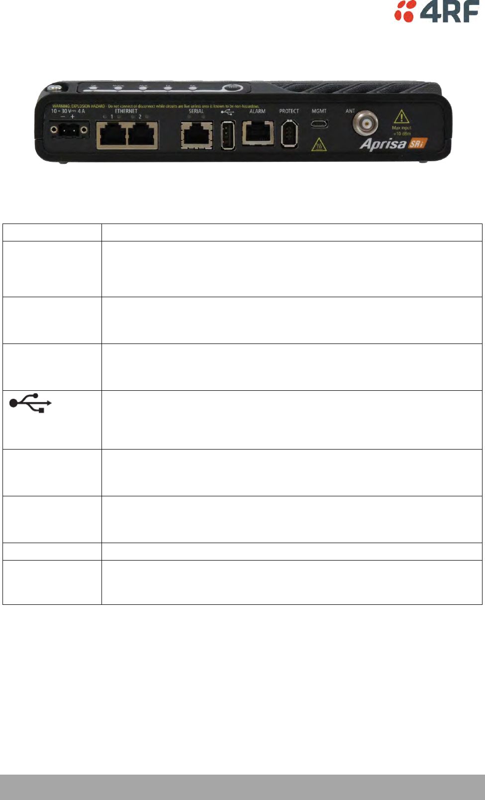
Front Panel Connections
All connections to the radio are made on the front panel. The functions of the connectors are (from left to
right):
Designator
Description
10 - 30 VDC; 3A
+10 to +30 VDC (negative ground) DC power input using Molex 2 pin male screw
fitting connector.
AC/DC and DC/DC power supplies are available as accessories. See ‘External
Power Supplies’ on page 59.
ETHERNET 1 & 2
Integrated 10Base-T/100Base-TX layer-3 Ethernet switch using RJ45 connectors.
Used for Ethernet user traffic and product management.
See ‘Ethernet > Port Setup’ on page 117.
SERIAL 1
One port of RS-232 serial using RJ45 connector.
Used for RS-232 asynchronous user traffic.
See ‘Serial > Port Setup’ on page 108.
Host Port using a USB standard type A connector.
Used for software upgrade and diagnostic reporting and optional: 1x RS-232
asynchronous port with USB to RS-232 converter.
See ‘Software Upgrade’ on page 266 and ‘Maintenance > General’ on page 185.
ALARM
Alarm Port using a RJ45 connector.
Used for two alarm inputs and two alarm outputs.
See ‘Hardware Alarms Interface’ on page 286.
MGMT
Management Port using a USB micro type B connector.
Used for product configuration with the Command Line Interface.
See ‘Connecting to the Management Port’ on page 253.
PROTECT
Protect port. Not used for the SRi.
ANT
TNC, 50 ohm, female connector for connection of antenna feeder cable for half
duplex RF operation.
See ‘Coaxial Feeder Cables’ on page 51.
About the Radio | 37
Aprisa SRi User Manual 1.0.0
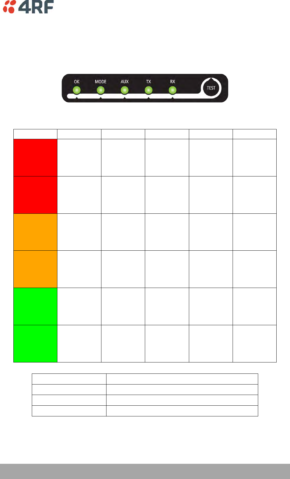
LED Display Panel
The Aprisa SRi has an LED Display panel which provides on-site alarms / diagnostics without the need for
PC.
The LEDs indicate the following conditions:
OK
MODE
AUX
TX
RX
Flashing
Red
Radio has not
registered
Solid
Red
Alarm present
with severity
Critical, Major
and Minor
TX path fail
RX path fail
Flashing
Orange
Diagnostics
Function
Active
OTA software
distribution
Management
traffic on the
USB MGMT
port
Solid
Orange
Alarm present
with Warning
Severity
Device detect
on the USB
host port
(momentary)
Flashing
Green
Software
Upgrade
Successful
Tx / Rx Data
on the USB
host port
RF path TX is
active
RF path RX is
active
Solid
Green
Power on and
functions OK
and no alarms
Processor
Block is OK
USB interface
OK
Tx path OK
Rx path OK
LED Colour
Severity
Green
No alarm – information only
Orange
Warning alarm
Red
Critical, major or minor alarm

38 | About the Radio
Aprisa SRi User Manual 1.0.0
Single Radio Software Upgrade
During a radio software upgrade, the LEDs indicate the following conditions:
Software upgrade started - the OK LED flashes orange
Software upgrade progress indicated by running AUX to MODE LEDs
Software upgrade completed successfully - the OK LED flashes green
Software upgrade failed - any LED flashing red during the upgrade
Network Software Upgrade
During a network software upgrade, the MODE LED flashes orange on the base station and all remote
stations.

About the Radio | 39
Aprisa SRi User Manual 1.0.0
Test Mode
Remote station radios have a Test Mode which presents a real time visual display of the RSSI on the LED
Display panel. This can be used to adjust the antenna for optimum signal strength.
To enter Test Mode, press and hold the TEST button on the radio LED panel until all the LEDs flash green
(about 3 - 5 seconds). The response time is variable and can be up to 5 seconds.
To exit Test Mode, press and hold the TEST button until all the LEDs flash red (about 3 – 5 seconds).
Note: Test Mode traffic has a low priority but could affect customer traffic depending on the relative
priorities setup.
The RSSI result is displayed on the LED Display panel as a combination of LED states:

40 | About the Radio
Aprisa SRi User Manual 1.0.0
Network Management
The Aprisa SRi contains an embedded web server application (SuperVisor) to enable element management
with any major web browser (such as Mozilla Firefox or Microsoft® Internet Explorer).
SuperVisor enables operators to configure and manage the Aprisa SRi base station radio and remote station
radios over the radio link.
The key features of SuperVisor are:
Full element management, configuration and diagnostics
Manage the entire network from the Base Station (remote management of elements)
Managed network software distribution and upgrades
Performance and alarm monitoring of the entire network, including RSSI, alarm states, time-
stamped events, etc.
View and set standard radio configuration parameters including frequencies, transmit power,
channel access, serial, Ethernet port settings
Set and view security parameters
User management
Operates over a secure HTTPS session on the access connection to the base station
SuperVisor, when connected to the base station radio allows management of all radios in the network. The
Network Table displays a list of all the registered remote stations for the base station and provides
management access to each of the remote stations (see ‘Network Status > Network Table’ on page 246).
About the Radio | 41
Aprisa SRi User Manual 1.0.0
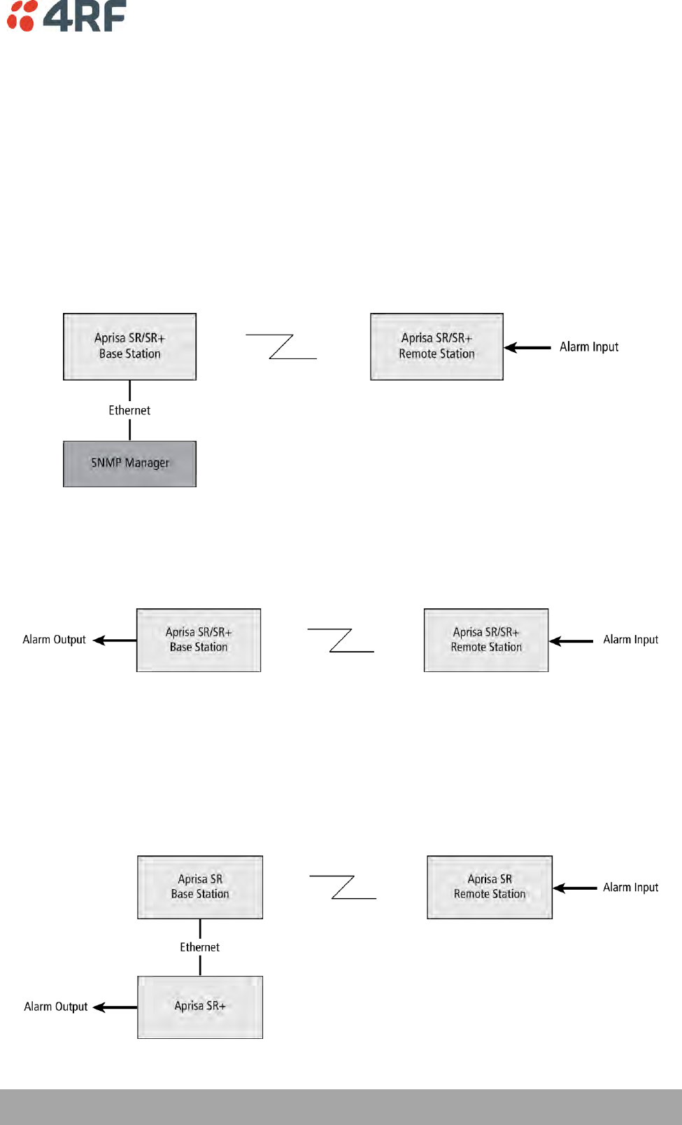
Hardware Alarm Inputs / Outputs
The Aprisa SRi provides two hardware alarm inputs to generate alarm events in the network and two
hardware alarm outputs to receive alarm events from the network.
The hardware alarm inputs and outputs are part of the event system. All alarm events can be viewed in
SuperVisor event history log (see ‘Events > Event History’ on page 198). These include the alarm events
generated by the hardware alarm inputs.
Alarm Input to SNMP Trap
An alarm event from an Aprisa SRi hardware alarm input can be sent over the air to any SNMP Manager
using SNMP traps.
Alarm Input to Alarm Output
An alarm event from an Aprisa SRi hardware alarm input can be mapped to an hardware alarm output of
another SRi using an event action setup (see ‘Events > Event Action Setup’ on page 205).
Aprisa SR Alarm Input to Aprisa SRi Alarm Output
The Aprisa SRi event action setup feature is compatible with the Aprisa SR.
Since, the Aprisa SR only supports hardware alarm inputs, the Aprisa SRi can be used as an option to
provide a hardware alarm output. As shown in the figure below, an Aprisa SRi connected on the same IP
network of the Aprisa SR, alarm events from the SR hardware alarm input can be mapped to the hardware
alarm output of the SRi using an event action setup.
42 | Implementing the Network
Aprisa SRi User Manual 1.0.0
4. Implementing the Network
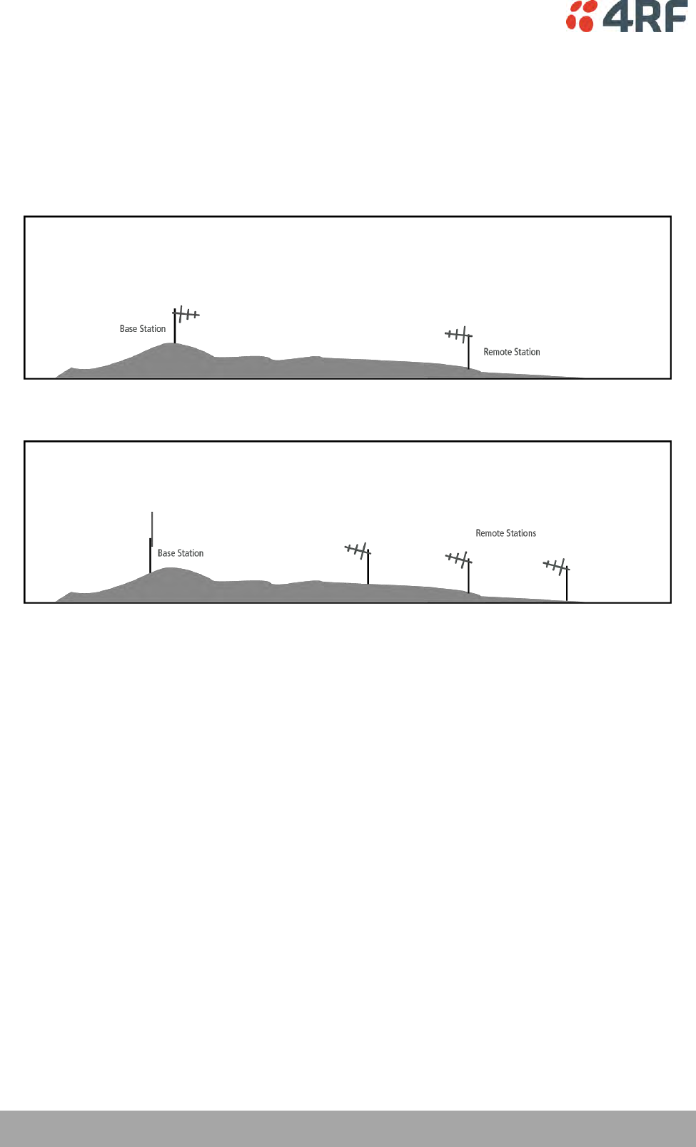
Network Topologies
The following are examples of typical network topologies:
Point-To-Point Network
Point-to-Multipoint Network

Implementing the Network | 43
Aprisa SRi User Manual 1.0.0
Initial Network Deployment
Install the Base Station
To install the base station in your network:
1. Install the base station radio (see ‘Installing the Radio’ on page 54).
2. Set the radio Network ID to a unique ID in your entire network (see ‘Terminal > Device’ on page 82).
3. Set the radio operating mode to ‘base station’ (see ‘Terminal > Operating Mode’ on page 86).
4. Set the radio IP address (see ‘IP > IP Setup > Bridge / Gateway Router Modes’ on page 129).
5. Set the radio zones / channels.
6. Set the radio security settings (see ‘Security > Setup’ on page 162).
Installing the Remote Stations
To install the remote stations in your network:
1. Install the remote station radio (see ‘Installing the Radio’ on page 54).
2. Set the radio Network ID to the same ID as the other stations in the network (see ‘Terminal > Device’
on page 82).
3. Set the radio operating mode to ‘remote station’ (see ‘Terminal > Operating Mode’ on page 86).
4. Set the radio IP address (see ‘IP > IP Setup > Bridge / Gateway Router Modes’ on page 129).
5. Set the radio zones / channels to be compatible with the base station.
6. Set the radio security settings to the same as the base station (see ‘Security > Setup’ on page 162).
The base station will automatically allocate a node address to the new remote station.

44 | Implementing the Network
Aprisa SRi User Manual 1.0.0
Network Changes
Adding a Remote Station
To add a remote station to your network:
1. Install the remote station radio (see ‘Installing the Radio’ on page 54).
2. Set the radio Network ID to the same ID as the other stations in the network (see ‘Terminal > Device’
on page 82).
3. Set the radio IP address (see ‘IP > IP Setup > Bridge / Gateway Router Modes’ on page 129).).
4. Set the radio zones / channels to be compatible with the base station.
5. Set the radio operating mode to ‘remote station’ (see ‘Terminal > Operating Mode’ on page 86).
The base station will automatically allocate a node address to the new remote station.
To remove a remote station from your network:
1. Turn the power off on the remote station radio you wish to remove. This is the only action that is
required.
Note: The remote station will continue to show in the Network Table list.
Preparation | 45
Aprisa SRi User Manual 1.0.0
5. Preparation
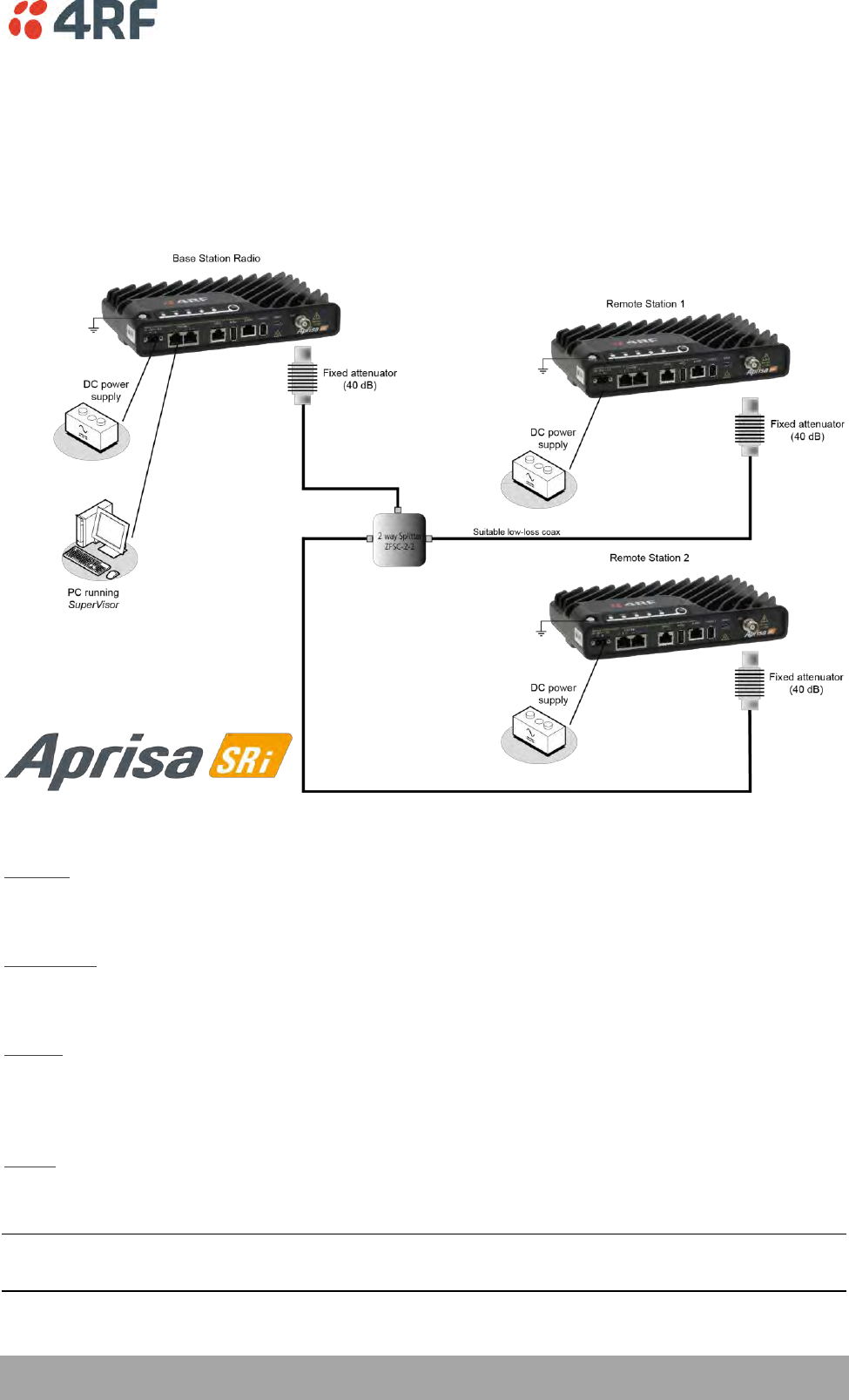
Bench Setup
Before installing the links in the field, it is recommended that you bench-test the links. A suggested setup
for basic bench testing is shown below:
When setting up the equipment for bench testing, note the following:
Earthing
Each radio should be earthed at all times. The radio earth point should be connected to a protection
earth.
Attenuators
In a bench setup, there should be 60 - 80 dB at up to 1 GHz of 50 ohm coaxial attenuation, capable of
handling the transmit power of +26 dBm (0.4 W) between the radios’ antenna connectors.
Splitter
If more than two radios are required in your bench setup, a multi-way splitter is required. The diagram
shows a two way splitter. This splitter should be 50 ohm coaxial up to 1 GHz and capable of handling the
transmit power of +26 dBm (0.4 W).
Cables
Use double-screened coaxial cable that is suitable for use up to 1 GHz at ≈ 1 metre.
CAUTION: Do not apply signals greater than +10 dBm to the antenna connection as they can damage the
receiver.
46 | Preparation
Aprisa SRi User Manual 1.0.0
Compliance Considerations
The Aprisa SRi is a professional radio product and as such must be installed by a suitably trained and
qualified installer who is aware of the local regulatory requirements existing at the time of installation
and is capable of ensuring that the regulations are adhered to.
The maximum Equivalent Isotropic Radiated Power (EIRP) permitted from the Aprisa SRi is regulated and
must not exceed the limits provided in the following table. To meet this regulatory requirement;
knowledge of the antenna gain and feeder cable loss must be known before setting the transmitter output
power.
Regulatory Requirement
Frequency Range
Maximum
EIRP1
SRi Equivalent
Maximum Average
Power (RdBm)
USA, FCC Part 15.247
902 MHz to 928 MHz
+36 dBm PEP
+32 dBm
Canada, IC RSS-247
902 MHz to 928 MHz
+36 dBm PEP
+32 dBm
Australia, ACMA AS/NZS 4268
915 MHz to 928 MHz
+30 dBm
+30 dBm
New Zealand, General User Radio
Licence for Short Rage Devices
915 MHz to 928 MHz
+30 dBm
+30 dBm
New Zealand, General User Radio
Licence for Short Rage Devices
920 MHz to 928 MHz
+36 dBm
+36 dBm
The Aprisa SRi has a maximum mean output power of +26 dBm into a 50 ohm antenna which equates to a
maximum peak power of +30 dBm PEP. To determine the maximum power to be set on the Aprisa SRi, the
following installation parameters must be known:
1.
Aprisa SRi equivalent average power for maximum permitted EIRP (specified in dBm)
RdBm
2.
Antenna isotropic gain (specified in dBi)
GdBi
3.
Feeder coax loss between Aprisa SRi and antenna (specified in dB/m)
LdB/m
4.
Length of feeder coax between Aprisa SRi and antenna (specified in metres)
dm
From these the above information, the power setting of the Aprisa SRi (PdBm) can be calculated to ensure
operation within the regulatory requirements using the formula:
Antenna gain information can be obtained from the Antenna manufacturer and is either expressed in
terms of dBi, referenced to an isotropic radiator, or dBd, referenced to a dipole.
If the gain is expressed in dBd, it can be converted to dBi by adding 2.15 dB to the gain value.
1
These are correct at the time of printing. The installer must ensure that the installation complies with the
regulatory requirements at the time of installation.

Preparation | 47
Aprisa SRi User Manual 1.0.0
This radio transmitter Aprisa SRi IC: 6772A-SI902M160 has been approved by Industry Canada to operate
with the antenna types listed below with the maximum permissible gain indicated. Antenna types not
included in this list, having a gain greater than the maximum gain indicated for that type, are strictly
prohibited for use with this device.
The following is an example of transmitter power calculations:
Antenna Type
and Gain
Feeder Coax Length and Loss
Regulatory
Limit
Maximum SRi
Power Setting
Yagi, 11 dBi
10 m of ½” Heliax @ 0.11 dB/m gives 1.1 dB loss
+36 dBm PEP
22 dBm
Panel, 12 dBi
33 m of RG214 @ 0.22 dB/m gives 7.3 dB loss
+30 dBm
25 dBm
Dipole, 3.5 dBi
3 m of RG214 @ 0.22 dB/m gives 0.66 dB loss
+30 dBm
26 dBm
Grid, 18 dBi
15 m of ½” Heliax @ 0.11 dB/m gives 1.65 dB loss
+30 dBm
13 dBm
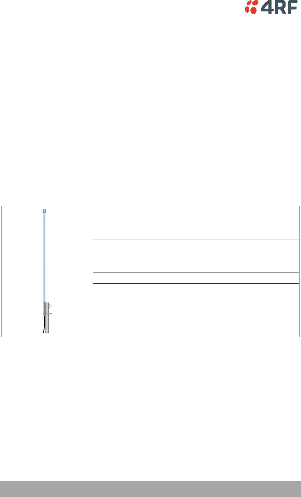
48 | Preparation
Aprisa SRi User Manual 1.0.0
Path Planning
The following factors should be considered to achieve optimum path planning:
Antenna Selection and Siting
Coaxial Cable Selection
Linking System Plan
Antenna Selection and Siting
Selecting and siting antennas are important considerations in your system design. The antenna choice for
the site is determined primarily by the frequency of operation and the gain required to establish reliable
links.
Base Station
The predominant antenna for a base station is an omni-directional collinear gain antenna.
Omni Directional Collinear Antennas
Factor
Explanation
Frequency
Often used in 380-530 MHz bands
Gain
Varies with size (5 dBi to 8 dBi typical)
Wind loading
Minimal
Tower aperture required
Minimal
Size
Range from 2 m to 3 m length
Polarization
Vertical
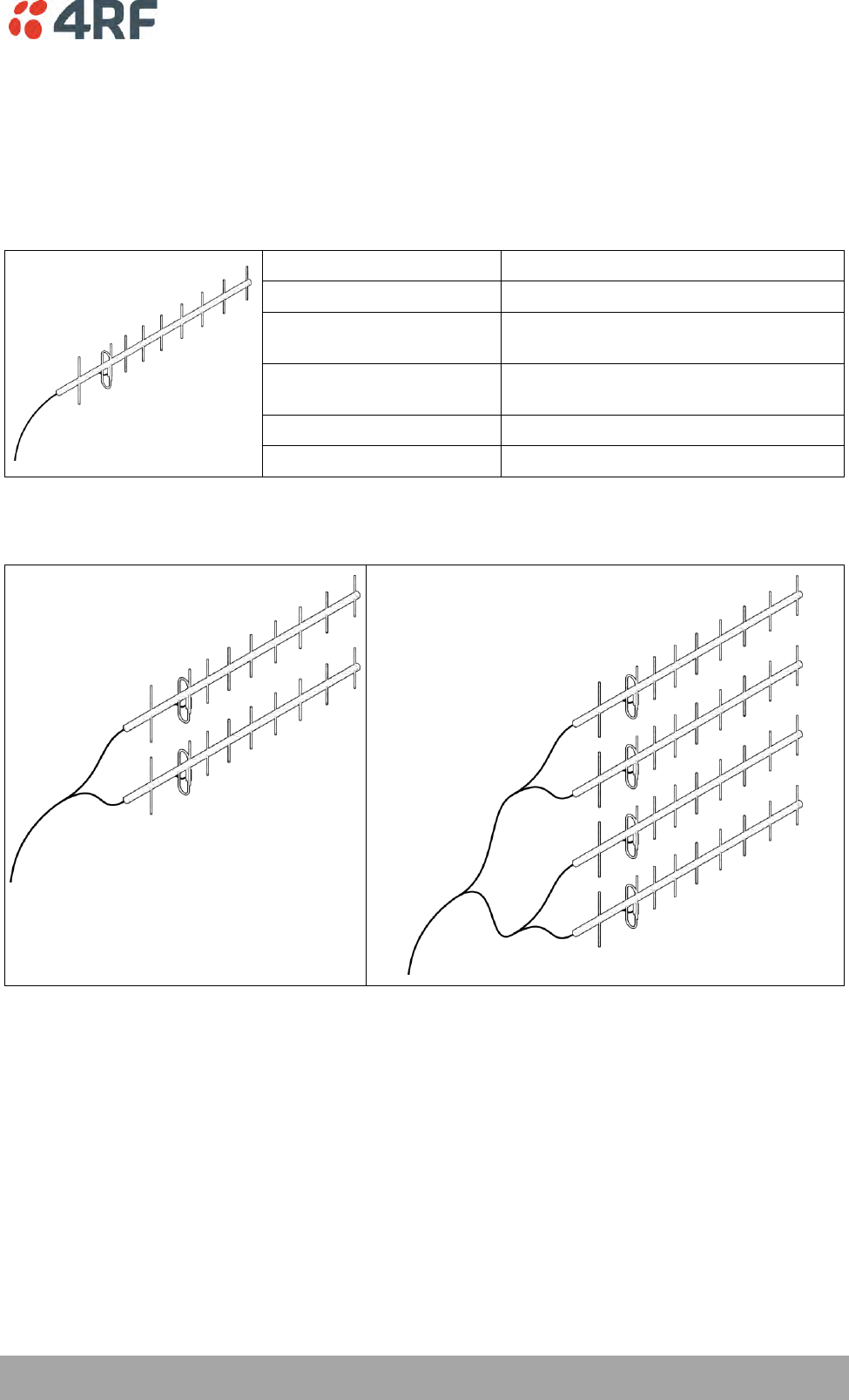
Preparation | 49
Aprisa SRi User Manual 1.0.0
Remote station
There are two main types of directional antenna that are commonly used for remote stations, Yagi and
corner reflector antennas.
Yagi Antennas
Factor
Explanation
Frequency
Often used in 350-600 MHz bands
Gain
Varies with size (typically 11 dBi to 16
dBi)
Stackable gain increase
2 Yagi antennas (+ 2.8 dB)
4 Yagi antennas (+ 5.6 dB)
Size
Range from 0.6 m to 3 m in length
Front to back ratio
Low (typically 18 to 20 dB)
It is possible to increase the gain of a Yagi antenna installation by placing two or more of them in a stack.
The relative position of the antennas is critical.
Example of stacked antennas
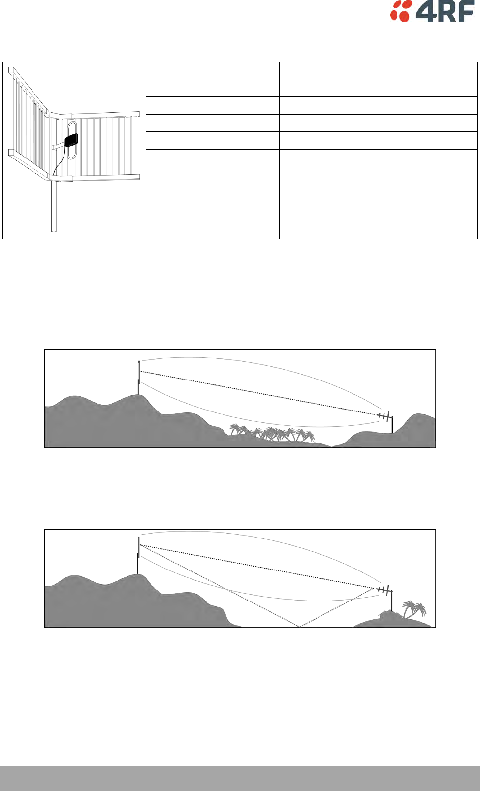
50 | Preparation
Aprisa SRi User Manual 1.0.0
Corner Reflector Antennas
Factor
Explanation
Frequency
Often used in 330-960 MHz bands
Gain
Typically 12 dBi
Size
Range from 0.36 m to 0.75 m in length
Front to back ratio
High (typically 30 dB)
Beamwidth
Broad (up to 60°)
Antenna Siting
When siting antennas, consider the following points:
A site with a clear line of sight to the remote radio is recommended. Pay particular attention to trees,
buildings, and other obstructions close to the antenna site.
Example of a clear line-of-sight path
Any large flat areas that reflect RF energy along the link path, for instance, water, could cause multipath
fading. If the link path crosses a feature that is likely to cause RF reflections, shield the antenna from the
reflected signals by positioning it on the far side of the roof of the equipment shelter or other structure.
Example of a mid-path reflection path
The antenna site should be as far as possible from other potential sources of RF interference such as
electrical equipment, power lines and roads. The antenna site should be as close as possible to the
equipment shelter.
Wide angle and zoom photographs taken at the proposed antenna location (looking down the proposed
path), can be useful when considering the best mounting positions.
Preparation | 51
Aprisa SRi User Manual 1.0.0
Coaxial Feeder Cables
To ensure maximum performance, it is recommended that you use good quality low-loss coaxial cable for
all feeder runs. When selecting a coaxial cable consider the following:
Factor
Effect
Attenuation
Short cables and larger diameter cables have less attenuation
Cost
Smaller diameter cables are cheaper
Ease of installation
Easier with smaller diameter cables or short cables
For installations requiring long feeder cable runs, use the RFI AVA5 50, RFI LDF4 50A or RFI CNT-400 feeder
cable or equivalent:
Part Number
Part Description
Specification
RFI AVA5 50
Feeder Cable, 7/8", HELIAX, Low loss
7/8" foam dielectric. Standard Jacket
Outer conductor corrugated copper, inner
conductor copper-clad aluminum
Bending radius of 250 mm min
Attenuation of 2.65 dB / 100m @ 520 MHz
RFI LDF4 50A
Feeder cable, 1/2", HELIAX, Loss Loss
1/2" foam dielectric. Standard Jacket
Outer conductor corrugated copper, inner
conductor copper-clad aluminum
Bending radius of 125 mm min
Attenuation of 5.1 dB / 100m @ 520 MHz
RFI CNT 400
Feeder, CNT-400, 10.8mm, Double
Shielded Solid Polyethylene
Low loss 0.4’ (10.8 mm) feeder cable
UV protected black Polyethylene, bonded
AL tape outer conductor
Bending radius of 30 mm min
Attenuation of 8.8 dB / 100m @ 450 MHz
For installations requiring short feeder cable runs, use the RFI 8223 feeder cable or equivalent:
Part Number
Part Description
Specification
RFI 8223
Feeder, RG 223 5.4mm d, Double
Shielded Solid Polyethylene
Bending radius of 20 mm min
Attenuation of 30.5 dB / 100m @ 450 MHz
When running cables:
Run coaxial feeder cable from the installation to the antenna, ensuring you leave enough extra cable at
each end to allow drip loops to be formed.
Terminate and ground the feeder cables in accordance with the manufacturers’ instructions. Bond the
outer conductor of the coaxial feeder cables to the base of the tower mast.
Linking System Plan
All of the above factors combine in any proposed installation to create a Linking System Plan. The Linking
System Plan predicts how well the radios will perform after it is installed.
Use the outputs of the Linking System Plan during commissioning to confirm the radios have been installed
correctly and that it will provide reliable service.
52 | Preparation
Aprisa SRi User Manual 1.0.0
Site Requirements
Power Supply
Ensure a suitable power supply is available for powering the radio.
The nominal input voltage for a radio is +13.8 VDC (negative earth) with an input voltage range of +10 to
+30 VDC. The maximum power input is 25 W.
WARNING:
Before connecting power to the radio, ensure that the radio is grounded via the
negative terminal of the DC power connection.
Equipment Cooling
If the Aprisa SRi is operated in an environment where the ambient temperature exceeds 50°C, the Aprisa
SRi convection air flow over the heat sinks must be considered.
The environmental operating conditions are as follows:
Operating temperature
-40 to +70˚ C
Storage temperature
-40 to +80˚ C
Humidity
Maximum 95% non-condensing
WARNING:
If the Aprisa SRi is operated in an environment where the ambient temperature
exceeds 50°C, the Aprisa SRi must be installed within a restricted access location to
prevent human contact with the enclosure heat sink.
WARNING:
The Aprisa SRi can be operated in an environment where the ambient temperature
exceeds 50°C. The heat sink will be a hot surface - do not touch.
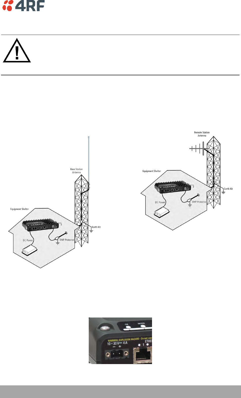
Preparation | 53
Aprisa SRi User Manual 1.0.0
Earthing and Lightning Protection
WARNING:
Lightning can easily damage electronic equipment.
To avoid this risk, install primary lightning protection devices on any interfaces that
are reticulated in the local cable network.
You should also install a coaxial surge suppressor on the radio antenna port.
Feeder Earthing
Earth the antenna tower, feeders and lightning protection devices in accordance with the appropriate
local and national standards. The diagram below shows the minimum requirements.
Use grounding kits as specified or supplied by the coaxial cable manufacturer to properly ground or bond
the cable outer.
Radio Earthing
The Aprisa SRi has an earth connection point on the top left of the enclosure. M4 8mm pan pozi machine
screws and M4 lock washers are supplied fitted to the radio. These screws can be used to earth the
enclosure to a protection earth.
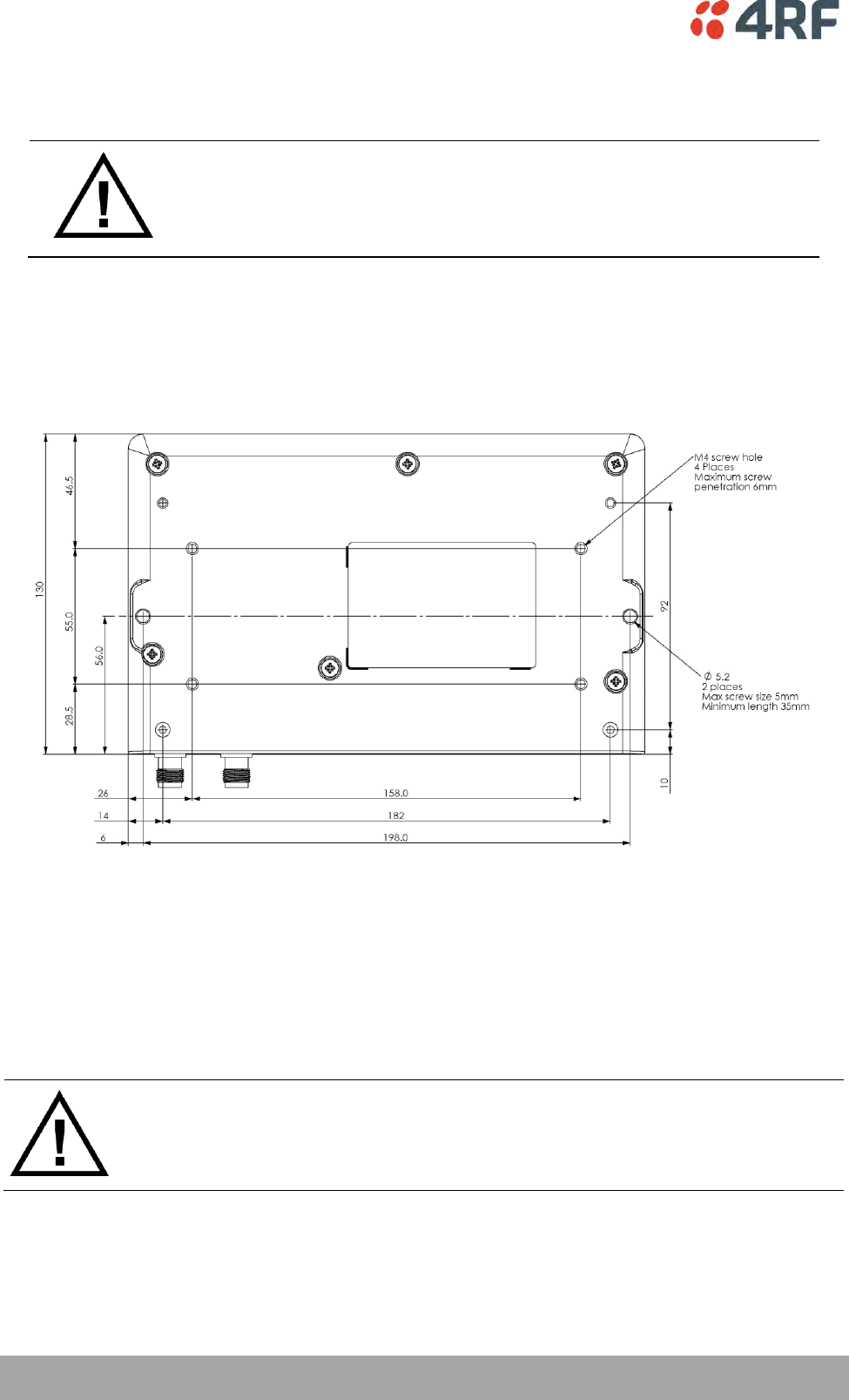
54 | Installing the Radio
Aprisa SRi User Manual 1.0.0
6. Installing the Radio
CAUTION:
You must comply with the safety precautions in this manual or on the product
itself.
4RF does not assume any liability for failure to comply with these precautions.
Mounting
The Aprisa SRi has four threaded holes (M4) in the enclosure base and two holes (5.2 mm) through the
enclosure for mounting.
Mounting options include:
DIN rail mounting with the Aprisa SRi DIN Rail Mounting Bracket
Rack shelf mounting
Wall mounting
Outdoor enclosure mounting
WARNING:
If the Aprisa SRi is operated in an environment where the ambient temperature
exceeds 50°C, the Aprisa SRi must be installed within a restricted access location to
prevent human contact with the enclosure heatsink.
Required Tools
No special tools are needed to install the radio.
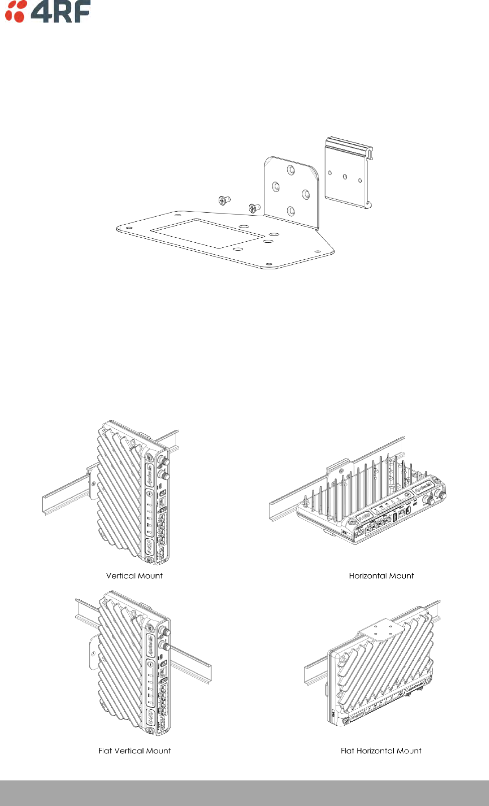
Installing the Radio | 55
Aprisa SRi User Manual 1.0.0
DIN Rail Mounting
The Aprisa SRi has an optional accessory part to enable the mounting on a standard DIN rail:
Part Number
Part Description
APSB-MBRK-DIN
4RF SRi Acc, Mounting, Bracket, DIN Rail
The Aprisa SRi is mounted into the DIN rail mounting bracket using the four M4 threaded holes in the
Aprisa SRi enclosure base. Four 8 mm M4 pan pozi machine screws are supplied with the bracket.
The Aprisa SRi DIN rail mounting bracket can be mounted in four positions on a horizontal DIN rail:
Vertical Mount (vertical enclosure perpendicular to the mount)
Horizontal Mount (horizontal enclosure perpendicular to the mount)
Flat Vertical Mount (vertical enclosure parallel to the mount)
Flat Horizontal Mount (horizontal enclosure parallel to the mount)
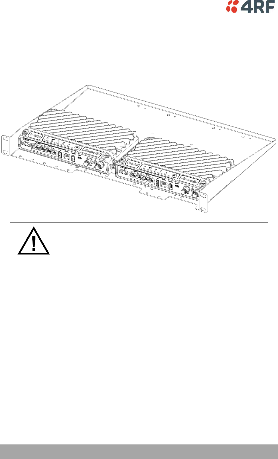
56 | Installing the Radio
Aprisa SRi User Manual 1.0.0
Rack Shelf Mounting
The Aprisa SRi can be mounted on a rack mount shelf using the four M4 threaded holes in the Aprisa SRi
enclosure base. The following picture shows Aprisa SRi mounted on a 1 RU rack mounted shelf.
Part Number
Part Description
APSB-MR19-X1U
4RF SRi Acc, Mounting, 19" Rack Mount Shelf, 1U
WARNING:
If the Aprisa SRi is operated in an environment where the ambient temperature
exceeds 50°C, the Aprisa SRi convection air flow over the heat sinks must be
considered.
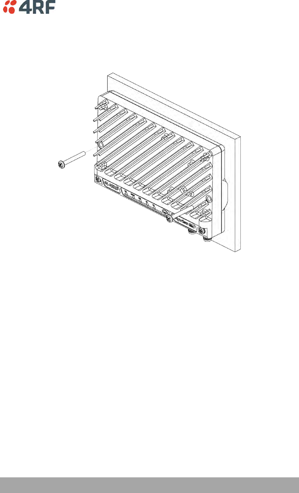
Installing the Radio | 57
Aprisa SRi User Manual 1.0.0
Wall Mounting
The Aprisa SRi can be mounted on a wall using the two holes through the enclosure (5.2 mm diameter).
Typically, M5 screws longer than 35 mm would be used.
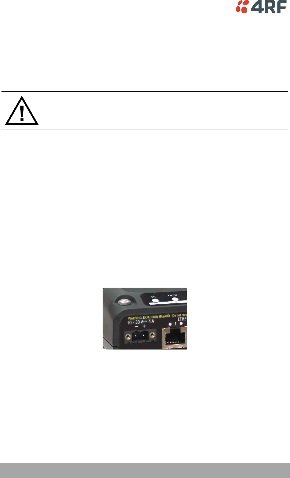
58 | Installing the Radio
Aprisa SRi User Manual 1.0.0
Installing the Antenna and Feeder Cable
Carefully mount the antenna following the antenna manufacturers’ instructions. Run feeder cable from
the antenna to the radio location.
Lightning protection must be incorporated into the antenna system (see ‘Earthing and Lightning
Protection’ on page 53).
WARNING:
When the link is operating, there is RF energy radiated from the antenna.
Do not stand in front of the antenna while the radio is operating (see the ‘RF
Exposure Warning’ on page 3).
Fit the appropriate male or female connector (usually N-type) to the antenna feeder at the antenna end.
Carefully follow the connector manufacturers’ instructions.
Securely attach the feeder cable to the mast and cable trays using cable ties or cable hangers. Follow the
cable manufacturer’s recommendations about the use of feeder clips, and their recommended spacing.
Connect the antenna and feeder cable. Weatherproof the connection with a boot, tape or other approved
method.
The Aprisa SRi antenna connection is a TNC female connector so the feeder / jumper must be fitted with a
TNC male connector.
If a jumper is used between the feeder and the radio, connect a coaxial surge suppressor or similar
lightning protector between the feeder and jumper cables (or at the point where the cable enters the
equipment shelter). Connect the feeder cable to the antenna port on the radio.
Earth the case of the lightning protector to the site Lightning Protection Earth.
The Aprisa SRi has an earth connection point on the top left of the enclosure. M4 8mm pan pozi machine
screws and M4 lock washers are supplied fitted to the radio. These screws can be used to earth the
enclosure to a protection earth.

Installing the Radio | 59
Aprisa SRi User Manual 1.0.0
Connecting the Power Supply
The nominal input voltage for a radio is +13.8 VDC (negative earth) with an input voltage range of +10 to
+30 VDC. The maximum power input is 25 W.
The power connector required is a Molex 2 pin female screw fitting part. This connector is supplied fitted
to the radio.
The negative supply of the Aprisa SRi power connection is internally connected to the Aprisa SRi
enclosure. Power must be supplied from a Negative Earthed power supply.
Wire your power source to power connector and plug the connector into the radio. The connector screws
can be fastened to secure the connector.
Spare Molex 2 pin female power connectors can be ordered from 4RF:
Part Number
Part Description
APST-CML2-FEM-01
4RF SRi Spare, Connector, Molex 2 pin, Female, 1 item
Turn your power source on:
All the radio LEDs will flash orange for one second and then the OK, MODE and AUX LEDs will light
green, the TX and RX LEDs will flash red.
The Aprisa SRi radio is ready to operate
The TX and RX LEDs will be green (steady or flashing) when the radio is registered with the
network.
If the LEDs fail to light, carefully check the supply polarity. If the power supply connections have been
accidentally reversed, internal fuses will have blown to protect the unit.
Spare fuses are contained within the radio, see ‘Spare Fuses’ on page 60 for instructions on how to locate
and replace the fuses.
External Power Supplies
The following external power supplies are available from 4RF as accessories:
Part Number
Part Description
APSB-P230-030-24-TS
4RF SRi Acc, PSU, 230 VAC, 30W, 24 VDC, -10 to +60C
APSB-P230-048-24-TE
4RF SRi Acc, PSU, 230 VAC, 48W, 24 VDC, -20 to +75C
APSB-P230-060-24-TS
4RF SRi Acc, PSU, 230 VAC, 60W, 24 VDC, -10 to +60C
APSB-P48D-050-24-TA
4RF SRi Acc, PSU, 48 VDC, 50W, 24 VDC, 0 to +50C
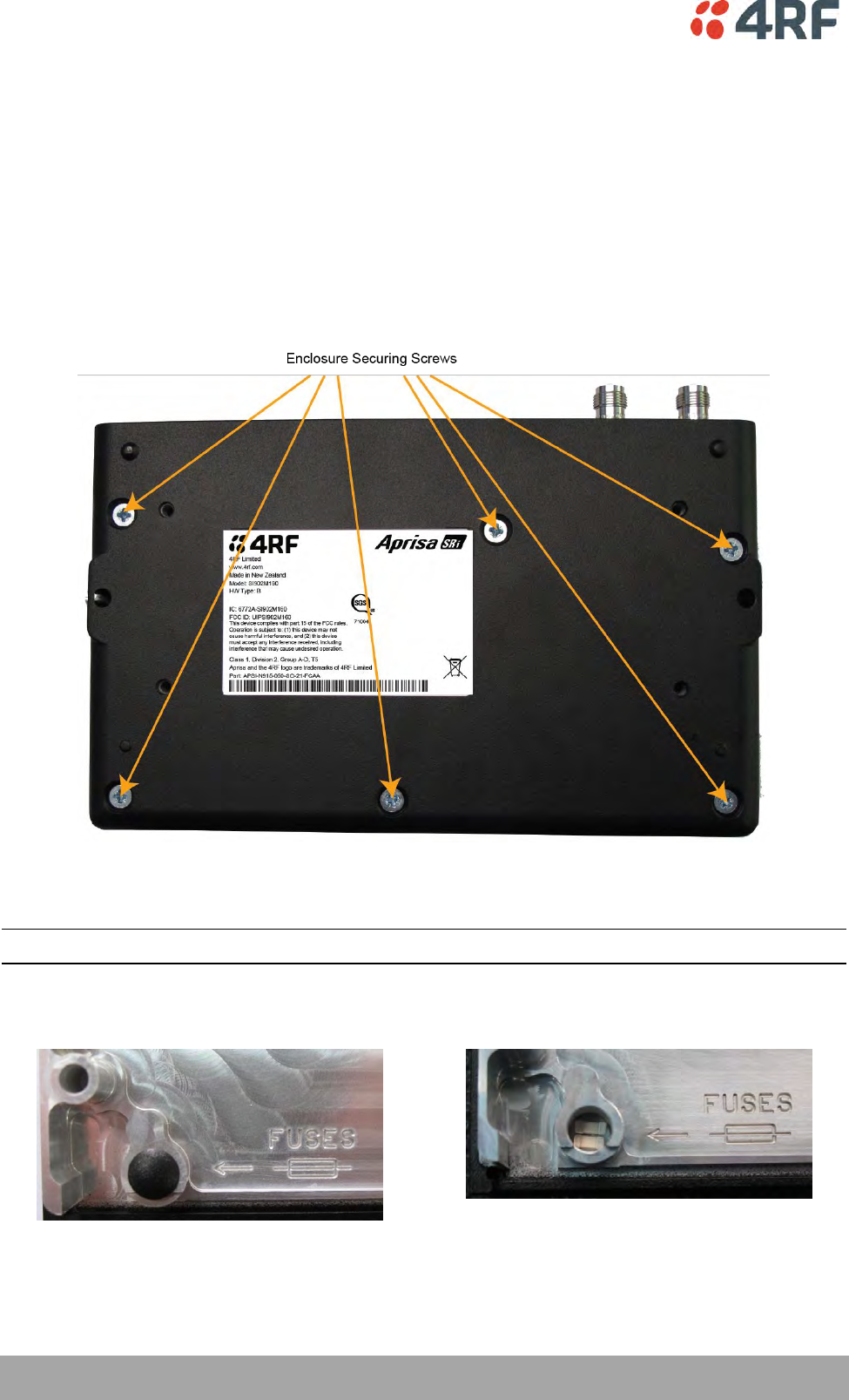
60 | Installing the Radio
Aprisa SRi User Manual 1.0.0
Spare Fuses
The Aprisa SRi PBA contains two fuses in the power input with designators F1 and F2. Both the positive and
negative power connections are fused. The fuse type is a Littelfuse 0454007 with a rating of 7 A, 75 V,
very fast acting.
To replace the fuses:
1. Remove the input power and antenna cable.
2. Unscrew the enclosure securing screws (posi 2).
2. Separate the enclosure halves.
CAUTION: Antistatic precautions must be taken as the internal components are static sensitive.
3. Access the enclosure spare fuses under the plastic cap.
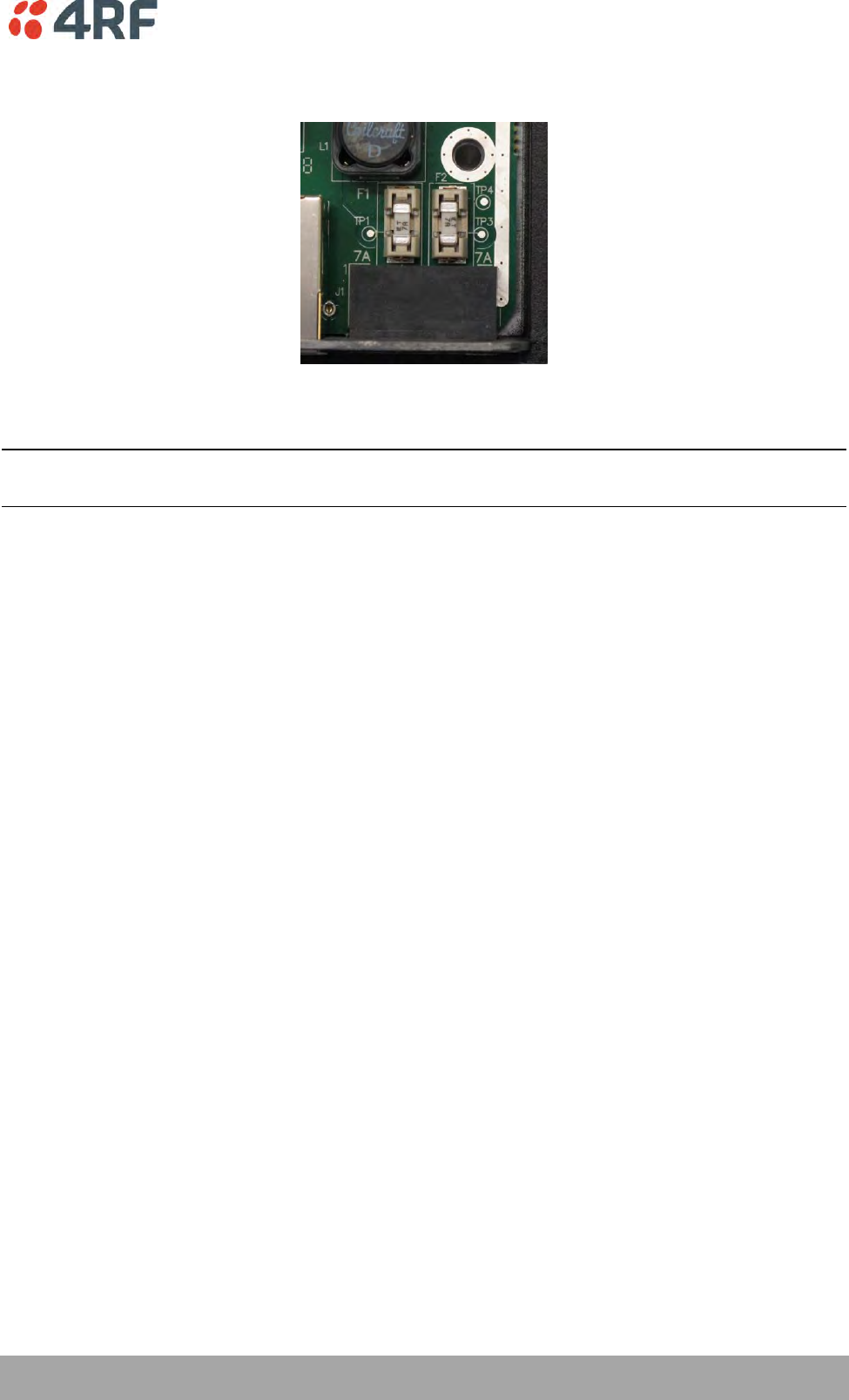
Installing the Radio | 61
Aprisa SRi User Manual 1.0.0
4. Replace the two fuses.
5. Close the enclosure and tighten the screws.
Note: Is it critical that the screws are re-tightened to 1.2 Nm. The transmitter adjacent channel
performance can be degraded if the screws are not tightened correctly.
Additional Spare Fuses
Additional spare fuses can be ordered from 4RF:
Part Number
Part Description
APST-FNAN-454-07-02
4RF SRi Spare, Fuse, Nano SMF, 454 Series, 7A, 2 items

Managing the Radio | 63
Aprisa SRi User Manual 1.0.0
7. Managing the Radio
SuperVisor
The Aprisa SRi contains an embedded web server application (SuperVisor) to enable element management
with any major web browser (such as Mozilla Firefox or Microsoft® Internet Explorer).
SuperVisor enables operators to configure and manage the Aprisa SRi base station radio and remote station
radios over the radio link.
The key features of SuperVisor are:
Full element management, configuration and diagnostics
Manage the entire network from the Base Station (remote management of elements)
Managed network software distribution and upgrades
Performance and alarm monitoring of the entire network, including alarm states, time-stamped
events, etc.
View and set standard radio configuration parameters including frequencies, transmit power,
channel access, serial, Ethernet port settings
Set and view security parameters
User management
Operates over a secure HTTPS session on the access connection to the base station

64 | Managing the Radio
Aprisa SRi User Manual 1.0.0
PC Requirements for SuperVisor
SuperVisor requires the following minimum PC requirements:
Browser
Operating System
Processor
RAM
Internet Explorer 7
(oldest browser supported)
IE7 can operate with less but will be
very slow.
MS-Windows XP
Service Pack 2
1 GHz processor
1 GB Ram
Internet Explorer 9
Does not support config file upload
from PC
MS-Windows Vista
Service Pack 2
1 GHz processor
2 GB Ram
Internet Explorer 10
(recommended minimum browser)
MS-Windows 7
Service Pack 1
1 GHz processor
2 GB Ram
Internet Explorer 11
MS-Windows 8.1
1 GHz processor
2 GB Ram
Mozilla Firefox (MS-Windows)
MS-Windows XP
Service Pack 2
1 GHz processor,
Pentium 4 and above
1 GB Ram
Mozilla Firefox (Linux)
Gnome desktop 2.18 and above
1 GHz processor,
Pentium 4 and above
1 GB Ram
Mozilla Firefox (Apple Mac)
(4RF does not support retina displays)
Mac OS X 10.6
1 GHz processor,
Pentium 4 and above
1 GB Ram
Note: 4RF does not support Google Chrome, Opera browser or Apple Safari but when they have been used
they have worked correctly.

Managing the Radio | 65
Aprisa SRi User Manual 1.0.0
Connecting to SuperVisor
The predominant management connection to the Aprisa SRi radio is with an Ethernet interface using
standard IP networking. There should be only one Ethernet connection from the base station to the
management network.
The Aprisa SRi has a factory default IP address of 169.254.50.10 with a subnet mask of 255.255.0.0. This is
an IPv4 Link Local (RFC3927) address which simplifies the connection to a PC.
Each radio in the network must be set up with a unique IP address on the same subnet.
To change the Aprisa SRi IP address:
1. Set up your PC for a compatible IP address e.g. 169.254.50.1 with a subnet mask of 255.255.0.0.
2. Connect your PC network port to one of the Aprisa SRi Ethernet ports.
3. Open a browser and enter https://169.254.50.10.
4. Login to the radio with the default Username ‘admin’ and Password ‘admin’.
5. Change the IP address to conform to the network plan in use.
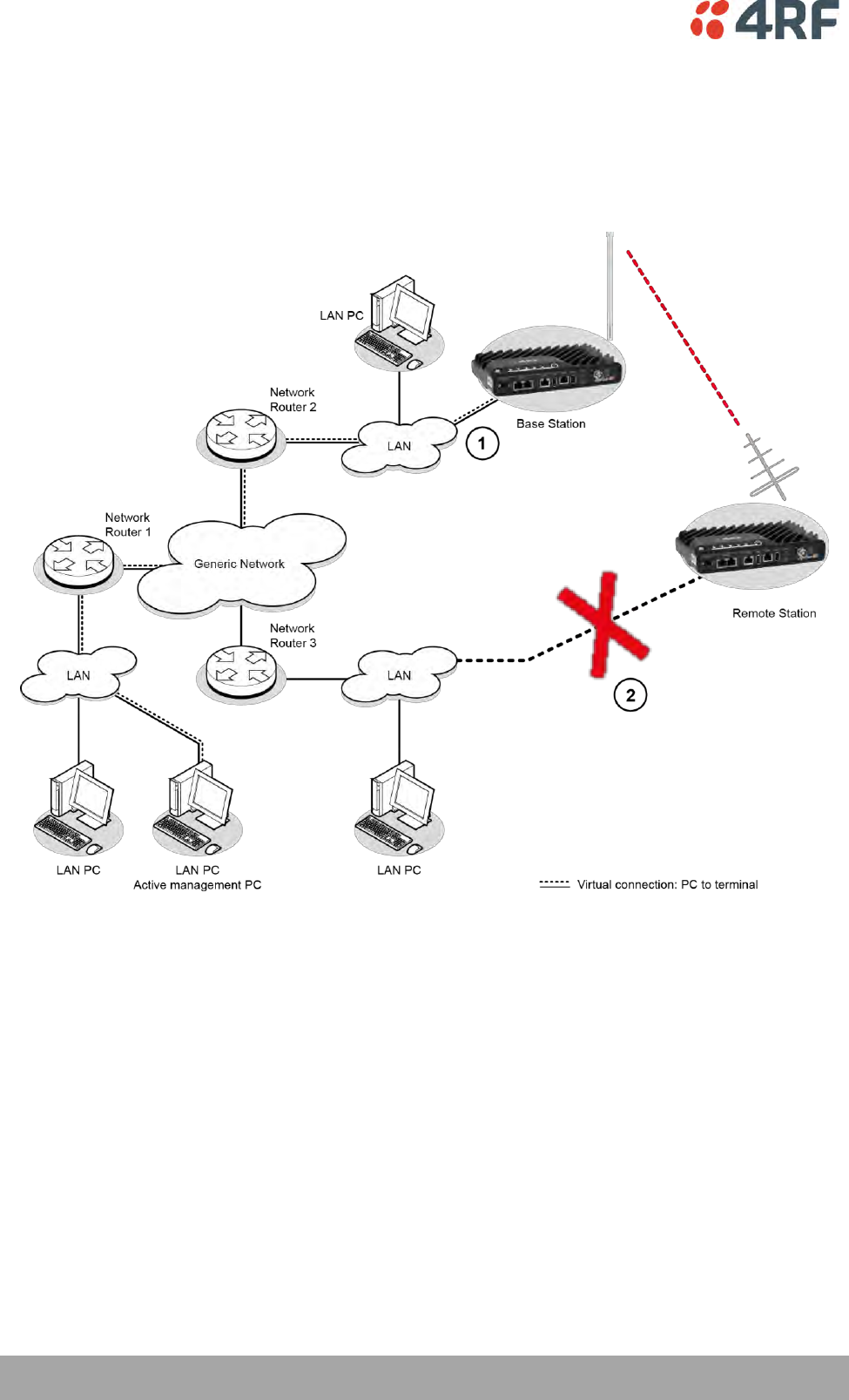
66 | Managing the Radio
Aprisa SRi User Manual 1.0.0
Management PC Connection
The active management PC must only have one connection to the network as shown by path . There
should not be any alternate path that the active management PC can use via an alternate router or
alternate LAN that would allow the management traffic to be looped as shown by path .
When logging into a network, it is important to understand the relationship between the Local Radio and
the Remote Radios.
The Local Radio is the radio that your IP network is physically connected to.
If the Local Radio is a base station, SuperVisor manages the base station and all the remote stations in the
network.
If the Local Radio is a remote station, SuperVisor only manages the remote station radio logged into.
If the user is at the remote station and connects SuperVisor directly to the remote radio via their
computer, all relevant features are still available. This includes the ability to monitor the ‘Last received
packet RSSI. If ICMP is enabled on the base station, the user will also be able to ping the base station to
confirm the connectivity.
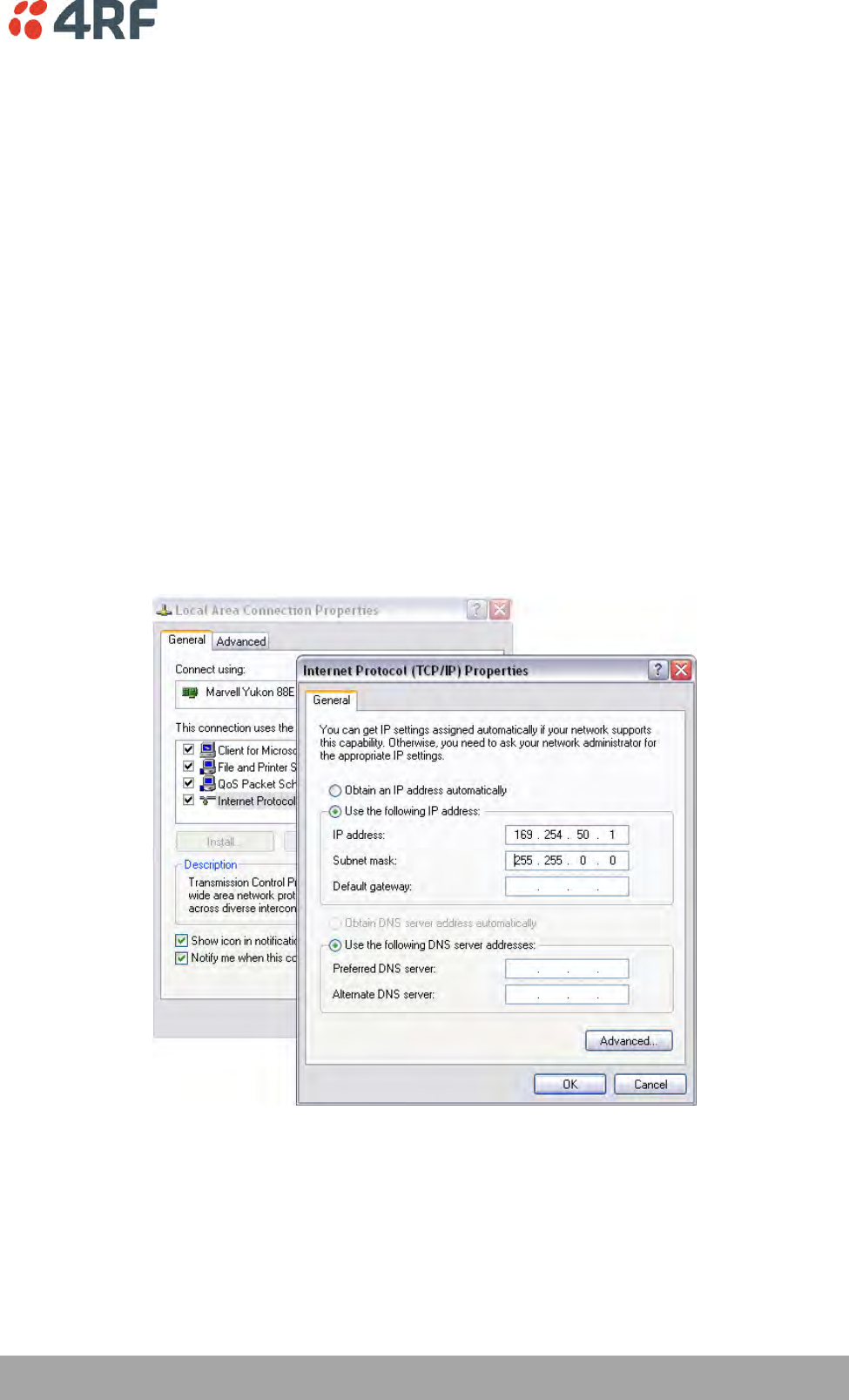
Managing the Radio | 67
Aprisa SRi User Manual 1.0.0
PC Settings for SuperVisor
To change the PC IP address:
If your PC has previously been used for other applications, you may need to change the IP address and the
subnet mask settings. You will require Administrator rights on your PC to change these.
Windows XP example:
1. Open the ‘Control Panel’.
2. Open ‘Network Connections’ and right click on the ‘Local Area Connection’ and select ‘Properties’.
3. Click on the ‘General’ tab.
4. Click on ‘Internet Protocol (TCP/IP)’ and click on properties.
5. Enter the IP address and the subnet mask (example as shown).
6. Click ‘OK’ then close the Control Panel.
If the radio is on a different subnet from the network the PC is on, set the PC default gateway address to
the network gateway address which is the address of the router used to connect the subnets (for details,
consult your network administrator).
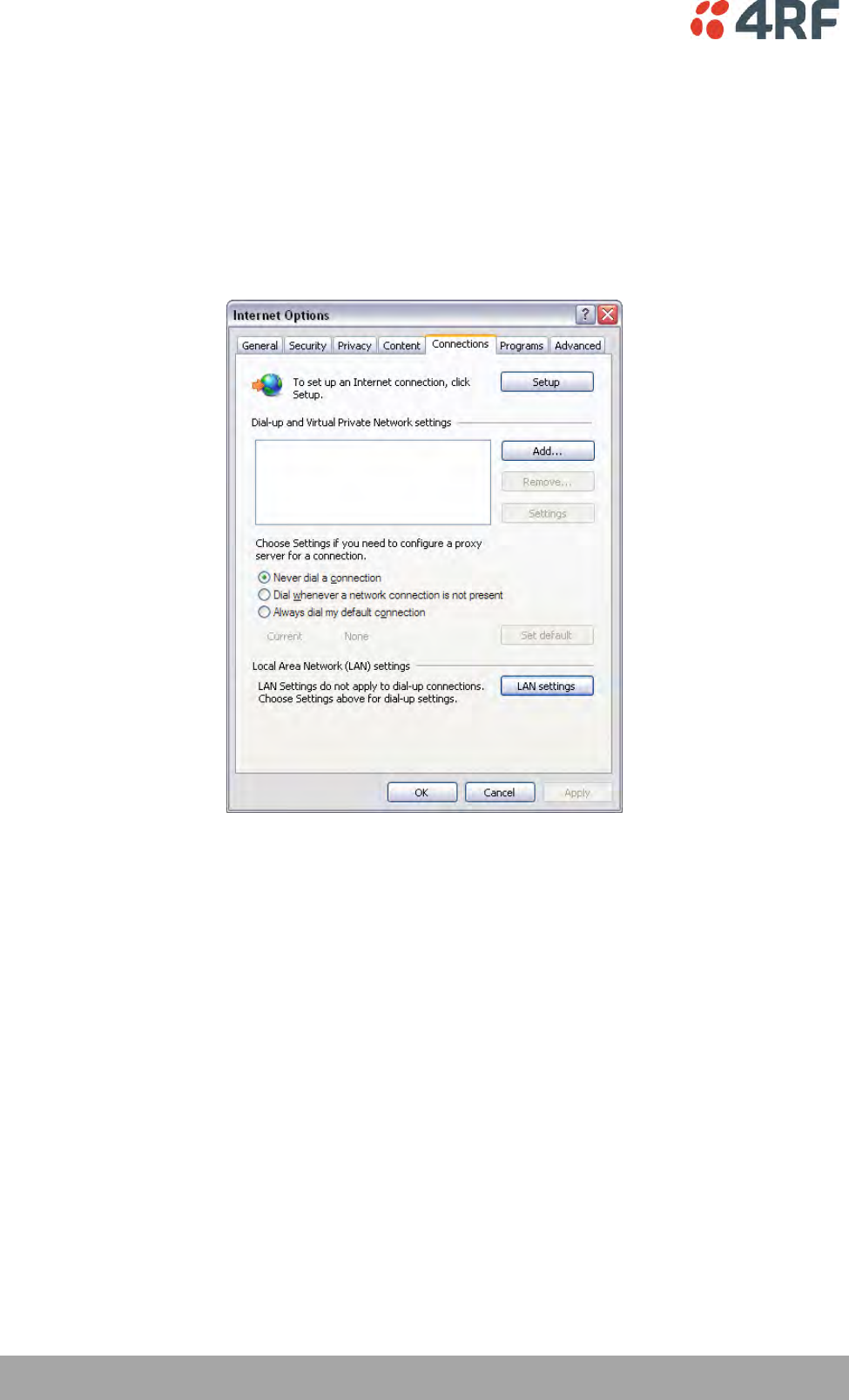
68 | Managing the Radio
Aprisa SRi User Manual 1.0.0
To change the PC connection type:
If your PC has previously been used with Dial-up connections, you may need to change your PC Internet
Connection setting to ‘Never dial a connection’.
Windows Internet Explorer 8 example:
1. Open Internet Explorer.
2. Open the menu item Tools > Internet Options and click on the ‘Connections’ tab.
3. Click the ‘Never dial a connection’ option.
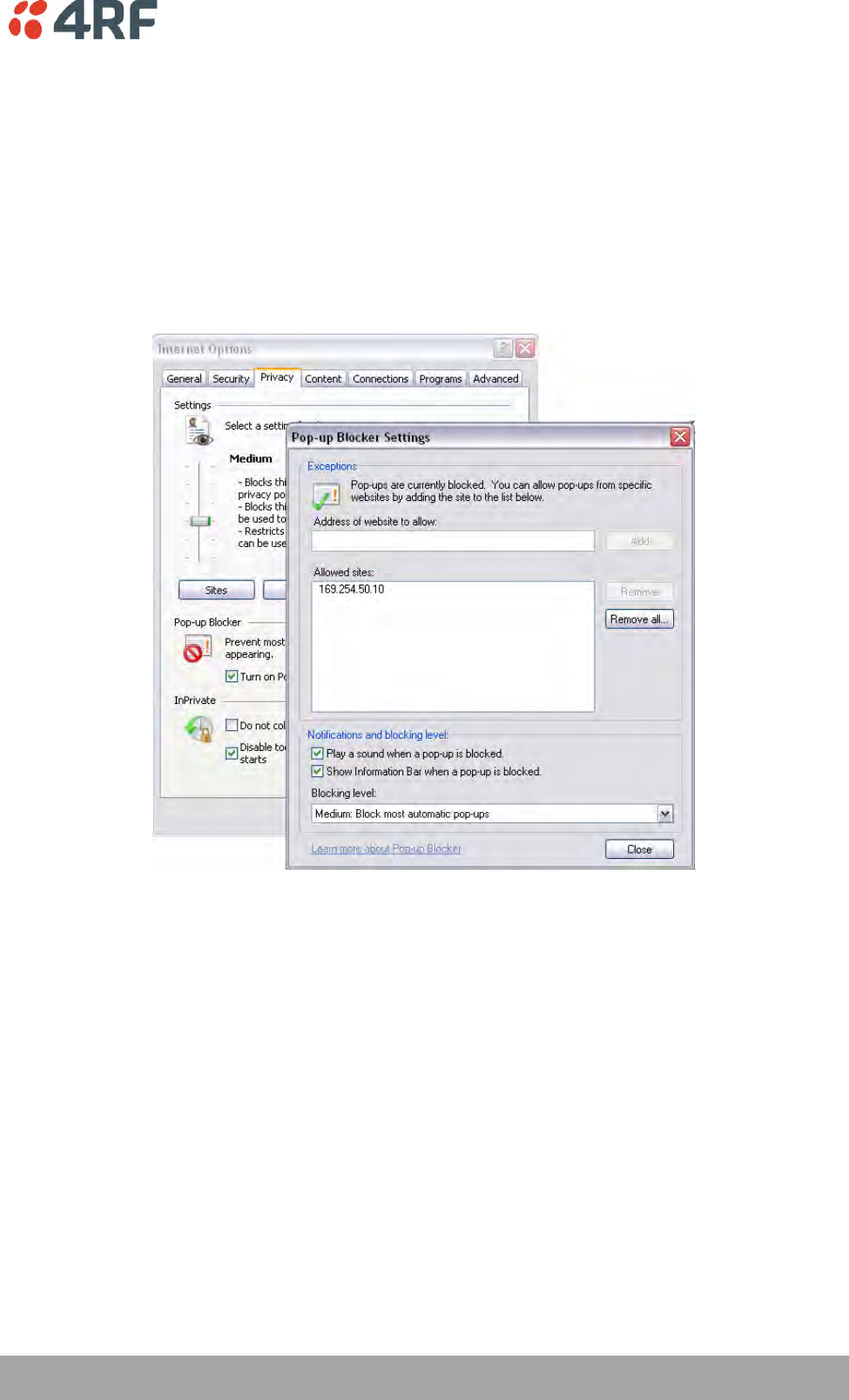
Managing the Radio | 69
Aprisa SRi User Manual 1.0.0
To change the PC pop-up status:
Some functions within SuperVisor require Pop-ups enabled e.g. saving a MIB
Windows Internet Explorer 8 example:
1. Open Internet Explorer.
2. Open the menu item Tools > Internet Options and click on the ‘Privacy’ tab.
3. Click on ‘Pop-up Blocker Settings’.
4. Set the ‘Address of Web site to allow’ to the radio address or set the ‘Blocking Level’ to ‘Low: Allow
Pop-ups from secure sites’ and close the window.
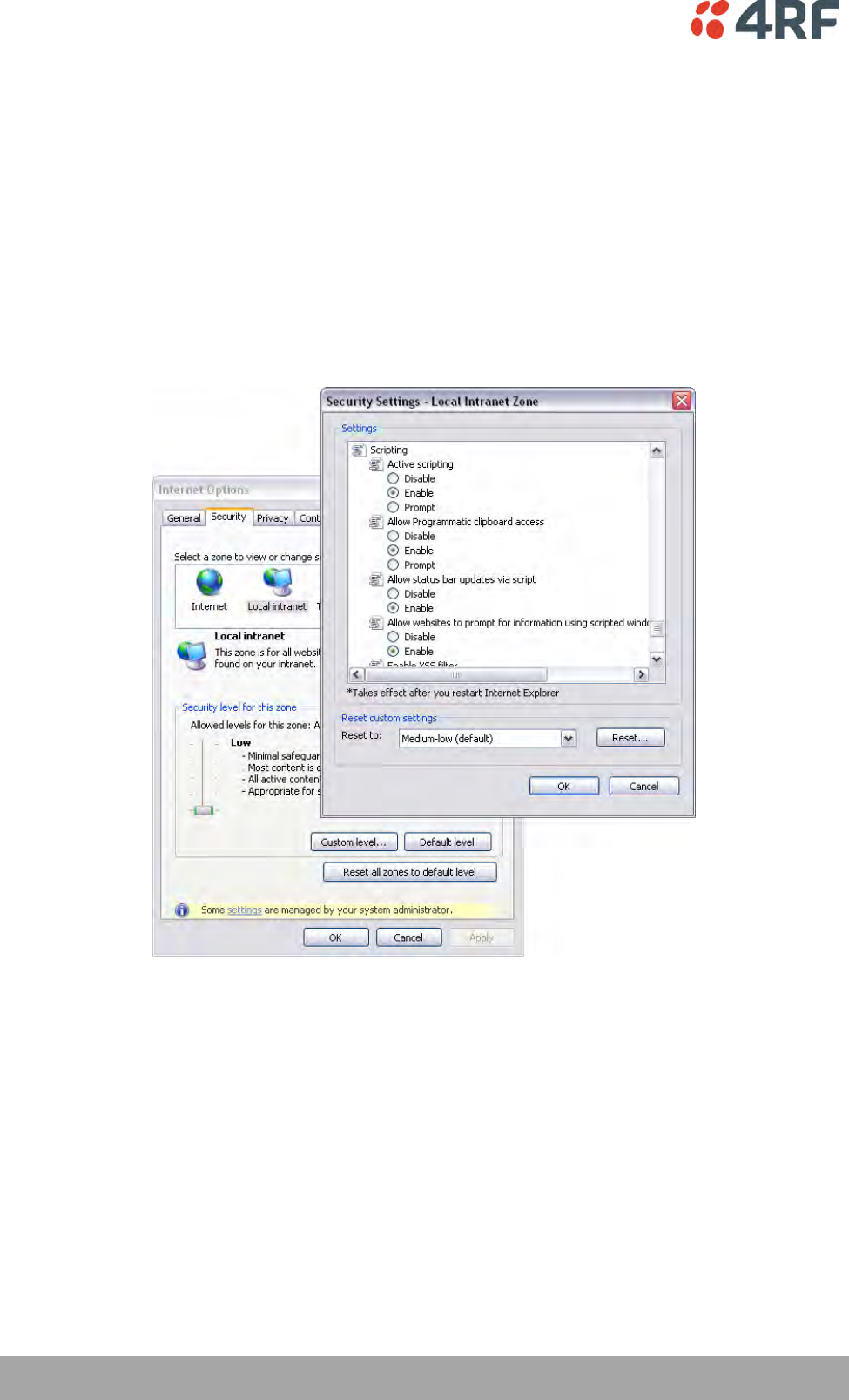
70 | Managing the Radio
Aprisa SRi User Manual 1.0.0
To enable JavaScript in the web browser:
Some functions within SuperVisor require JavaScript in the web browser to be enabled.
Windows Internet Explorer 8 example:
1. Open Internet Explorer.
2. Open the menu item Tools > Internet Options and click on the ‘Security’ tab.
3. Click on ‘Local Intranet’.
4. Click on ‘Custom Level’.
5. Scroll down until you see section labeled ‘Scripting’.
6. Under ‘Active Scripting’, select ‘Enable’.
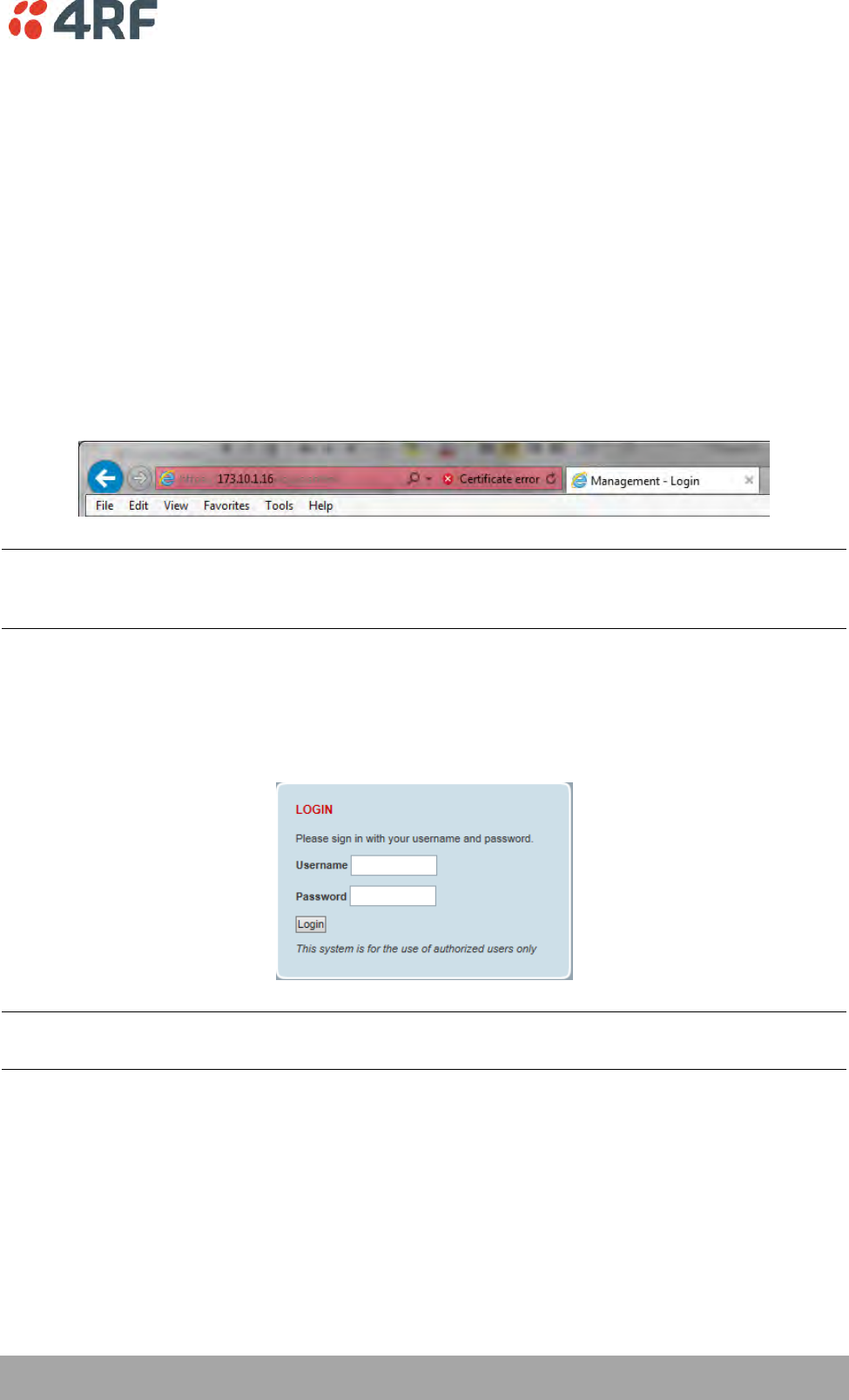
Managing the Radio | 71
Aprisa SRi User Manual 1.0.0
Login to SuperVisor
The maximum number of concurrent users that can be logged into a radio is 6.
If SuperVisor is inactive for a period defined by the Inactivity Timeout option (see ‘Maintenance > General’
on page 185), the radio will automatically logout the user.
To login to SuperVisor:
1. Open your web browser and enter the IP address of the radio.
If you haven’t assigned an IP address to the radio, use the factory default IP address of 169.254.50.10 with
a subnet mask of 255.255.0.0.
If you don’t know the IP address of the radio, you can determine it using the Command Line Interface (see
‘Command Line Interface’ on page 253).
Note: The Aprisa SRi has a randomly generated unique self-signed ECC256 security certificate which may
cause the browser to prompt a certificate warning. It is safe to ignore the warning and continue. The valid
certificate is ‘Issued By: 4RF-APRISA’ which can be viewed in the browser.
2. Login with the Username and Password assigned to you.
If unique usernames and passwords have not yet been configured, use the default username ‘admin’ and
password ‘admin’.
Important: After you login for the very first time, it is recommended that you change the default admin
password for security reasons (see ‘Changing Passwords’ on page 171).
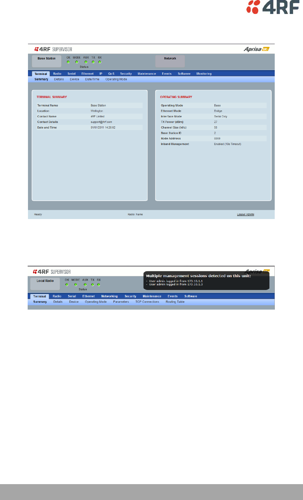
72 | Managing the Radio
Aprisa SRi User Manual 1.0.0
If the login is successful, the opening page will be displayed.
If there is more than one user logged into the same radio, the Multiple Management Sessions popup will
show the usernames and IP addresses of the users. This popup message will display until 5 seconds after
the cursor is moved. The event log will also record the users logged into the radio or logged out the radio.
Logout of SuperVisor
As the maximum number of concurrent users that can be logged into a radio is 6, not logging out correctly
can restrict access to the radio until after the timeout period (30 minutes).
Logging out from a radio will logout all users logged in with the same username.
If the SuperVisor window is closed without logging out, the radio will automatically log the user out after a
timeout period of 3 minutes.
To logout of SuperVisor:
Click on the ‘Logout’ button on the Summary Bar.
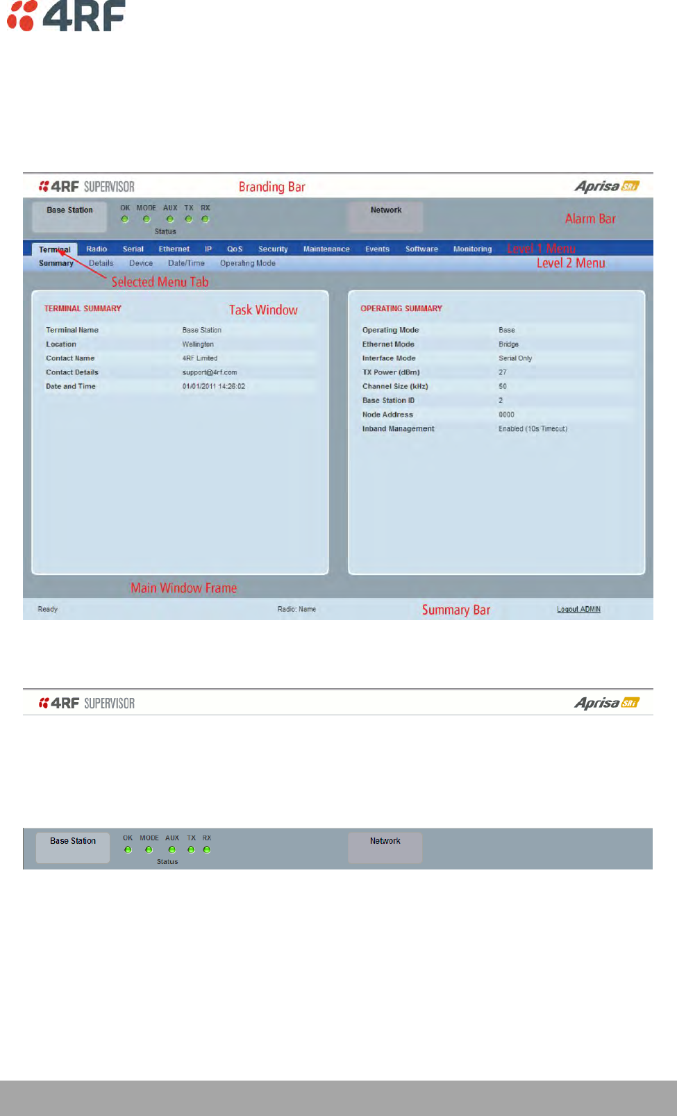
Managing the Radio | 73
Aprisa SRi User Manual 1.0.0
SuperVisor Page Layout
Standard Radio
The following shows the components of the SuperVisor page layout for a standard radio:
SuperVisor Branding Bar
The branding bar at the top of the SuperVisor frame shows the branding of SuperVisor on the left and the
product branding on the right.
SuperVisor Alarm Bar
The alarm bar shows the name of the radio terminal that SuperVisor is logged into (the local radio) on the
left.
If the local radio is a base station, the page shows the name of the current remote station (the remote
radio) on the right. SuperVisor will manage all the remote stations in the network.
If the local radio is a remote station, the page shows the name of the remote station on the left. The right
side of the Alarm Bar will be blank. SuperVisor manages only the remote station logged into.
The LED alarm indicators reflect the status of the front panel LEDs on the radio.

74 | Managing the Radio
Aprisa SRi User Manual 1.0.0
SuperVisor Summary Bar
The summary bar at the bottom of the page shows:
Position
Function
Left
Busy - SuperVisor is busy retrieving data from the radio that
SuperVisor is logged into.
Ready - SuperVisor is ready to manage the radio.
Middle
Displays the name of the radio terminal that SuperVisor is currently
managing.
Right
The access level logged into SuperVisor. This label also doubles as
the SuperVisor logout button.

Managing the Radio | 75
Aprisa SRi User Manual 1.0.0
SuperVisor Menu
The following is a list of SuperVisor top level menu items:
Local Terminal
Network
Network Table
Terminal
Summary
Radio
Exceptions
Serial
View
Ethernet
IP
QoS
Security
Maintenance
Events
Software
Monitoring
SuperVisor Parameter Settings
Changes to parameters settings have no effect until the ‘Save’ button is clicked.
Click the ‘Save’ button to apply the changes or ‘Cancel’ button to restore the current value.

76 | Managing the Radio
Aprisa SRi User Manual 1.0.0
SuperVisor Menu Access
The SuperVisor menu has varying access levels dependent on the login User Privileges.
The following is a list of all possible SuperVisor menu items versus user privileges:
Terminal Settings Menu Items
Menu Item
View
Technician
Engineer
Admin
Terminal > Summary
Read-Only
Read-Only
Read-Only
Read-Only
Terminal > Details
Read-Only
Read-Only
Read-Only
Read-Only
Terminal > Device
No Access
Read-Write
Read-Write
Read-Write
Terminal > Date / Time
Read-Only
Read-Only
Read-Only
Read-Only
Terminal > Operating Mode
No Access
Read-Write
Read-Write
Read-Write
Radio > Radio Summary
Read-Only
Read-Only
Read-Only
Read-Only
Radio > Channel Summary
Read-Only
Read-Only
Read-Only
Read-Only
Radio > Zone Summary
Read-Only
Read-Only
Read-Only
Read-Only
Radio > Radio Setup
No Access
Read-Write
Read-Write
Read-Write
Radio > Channel Setup
No Access
Read-Write
Read-Write
Read-Write
Radio > Zone Setup
No Access
Read-Write
Read-Write
Read-Write
Radio > Advanced Setup
No Access
Read-Write
Read-Write
Read-Write
Serial > Summary
Read-Only
Read-Only
Read-Only
Read-Only
Serial > Port Setup
No Access
Read-Write
Read-Write
Read-Write
Ethernet > Summary
Read-Only
Read-Only
Read-Only
Read-Only
Ethernet > Port Setup
No Access
Read-Write
Read-Write
Read-Write
Ethernet > L2 Filtering
No Access
No Access
Read-Write
Read-Write
Ethernet > VLAN
No Access
No Access
Read-Write
Read-Write
IP > IP Summary
Read-Only
Read-Only
Read-Only
Read-Only
IP > Terminal Server Summary
Read-Only
Read-Only
Read-Only
Read-Only
IP > IP Setup
No Access
Read-Write
Read-Write
Read-Write
IP > Terminal Server Setup
No Access
Read-Write
Read-Write
Read-Write
IP > L3 Filtering
No Access
No Access
Read-Write
Read-Write
IP > IP Routes
No Access
No Access
Read-Write
Read-Write
QoS > Summary
Read-Only
Read-Only
Read-Only
Read-Only
QoS > Traffic Priority
No Access
No Access
Read-Write
Read-Write
QoS > Traffic Classification
No Access
No Access
Read-Write
Read-Write
Security > Summary
Read-Only
Read-Only
Read-Only
Read-Only
Security > Setup
No Access
No Access
Read-Write
Read-Write
Security > Users
No Access
No Access
No Access
Read-Write
Security > RADIUS
No Access
No Access
No Access
Read-Write
Security > SNMP
No Access
No Access
No Access
Read-Write
Security > Manager
No Access
No Access
Read-Write
Read-Write
Security > Distribution
No Access
No Access
Read-Write
Read-Write
Maintenance > Summary
Read-Only
Read-Only
Read-Only
Read-Only
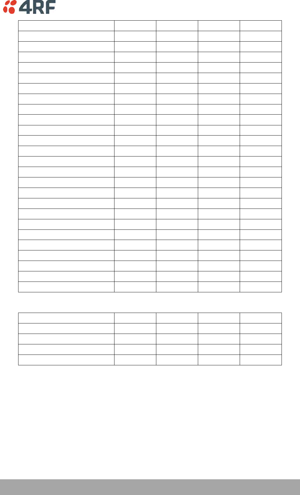
Managing the Radio | 77
Aprisa SRi User Manual 1.0.0
Menu Item
View
Technician
Engineer
Admin
Maintenance > General
No Access
Read-Write
Read-Write
Read-Write
Maintenance > Defaults
No Access
No Access
No Access
Read-Write
Maintenance > Licence
No Access
No Access
Read-Write
Read-Write
Maintenance > Advanced
No Access
No Access
Read-Write
Read-Write
Events > Alarm Summary
Read-Only
Read-Only
Read-Only
Read-Only
Events > Event History
Read-Only
Read-Only
Read-Only
Read-Only
Events > Events Setup
No Access
No Access
Read-Write
Read-Write
Events > Traps Setup
No Access
No Access
Read-Write
Read-Write
Events > Alarm I/O Setup
Read-Only
Read-Only
Read-Write
Read-Write
Events > Event Action Setup
No Access
No Access
Read-Write
Read-Write
Events > Defaults
No Access
No Access
Read-Write
Read-Write
Software > Summary
Read-Only
Read-Only
Read-Only
Read-Only
Software > Setup
No Access
No Access
Read-Write
Read-Write
Software > File Transfer
No Access
No Access
Read-Write
Read-Write
Software > Manager
No Access
No Access
Read-Write
Read-Write
Software > Remote Distribution
No Access
No Access
Read-Write
Read-Write
Software > Remote Activation
No Access
No Access
Read-Write
Read-Write
Monitoring > Terminal
Read-Only
Read-Only
Read-Only
Read-Only
Monitoring > Serial
Read-Only
Read-Only
Read-Only
Read-Only
Monitoring > Ethernet
Read-Only
Read-Only
Read-Only
Read-Only
Monitoring > Radio
Read-Only
Read-Only
Read-Only
Read-Only
Monitoring > User Selected
Read-Only
Read-Only
Read-Only
Read-Only
Monitoring > TCP Connections
Read-Only
Read-Only
Read-Only
Read-Only
Monitoring > Routing Table
Read-Only
Read-Only
Read-Only
Read-Only
Monitoring > Address Tables
Read-Only
Read-Only
Read-Only
Read-Only
Network Settings Menu Items
Menu Item
View
Technician
Engineer
Admin
Network Table
Read-Only
Read-Only
Read-Only
Read-Only
Summary
Read-Only
Read-Only
Read-Only
Read-Only
Exceptions
Read-Only
Read-Only
Read-Only
Read-Only
View
Read-Only
Read-Only
Read-Only
Read-Only
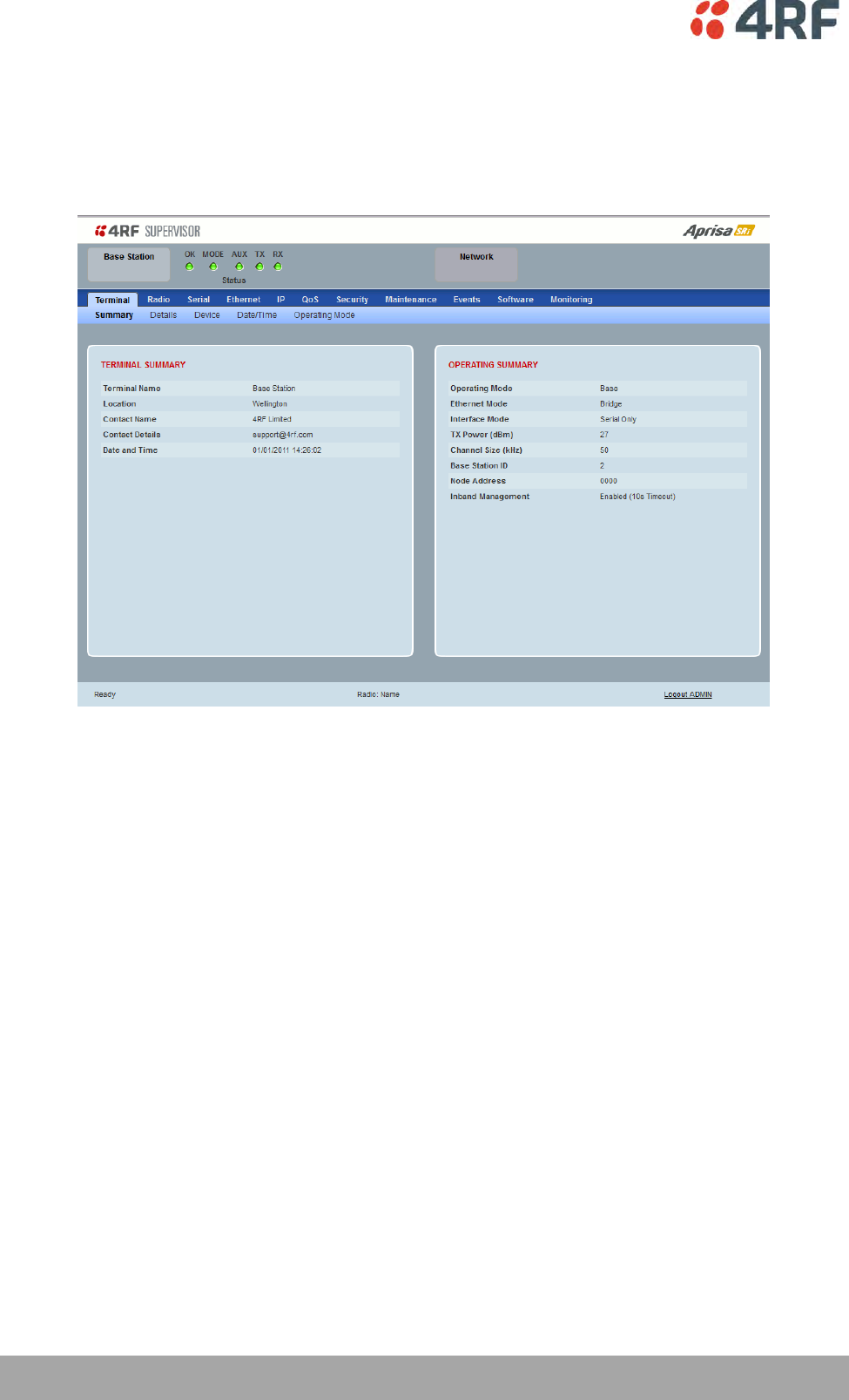
78 | Managing the Radio
Aprisa SRi User Manual 1.0.0
Standard Radio
Terminal
Terminal > Summary
TERMINAL SUMMARY
This page displays the current settings for the Terminal parameters. See ‘Terminal > Details’ on page 80,
‘Terminal > Device’ on page 82 and ‘Terminal > Operating Mode’ on page 86 for setting details.
OPERATING SUMMARY
Operating Mode
This parameter displays the current Operating Mode i.e. if the radio is operating as a base station or
remote station and the network operating mode of Bridge Mode or Router Mode.
Interface Mode
This parameter displays the Interfaces available for traffic on the radio such as Ethernet and Serial. For
Ethernet availability on the radio see ‘Maintenance > Licence’ on page 191.
TX Power (dBm)
This parameter displays the current Transmit Power in dBm.
Channel Size (kHz)
This parameter displays the current Channel Size in kHz.

Managing the Radio | 79
Aprisa SRi User Manual 1.0.0
Base Station ID
This parameter identifies the base station. All radios operating to the base station in the same network
must use the same Base Station ID setting.
It is especially important to set different values for each network when two or more networks using the
same frequencies are operating with some overlapping coverage. The entry is an integer from 1 to 8.
Node Address
The Node Address of the base station is 0000.
If the Node Address shown is FFFE, this radio is a remote station but has not been registered with the base
station.
The base station will automatically allocate a Node Address to all its registered remote station radios. This
address can be between 000B to 01FE.
Inband Management
This parameter displays the status of the Inband Management option.
Inband Management Timeout (sec)
This parameter displays the number of seconds that the base station waits for a response from a remote
station before aborting the Inband Management request.
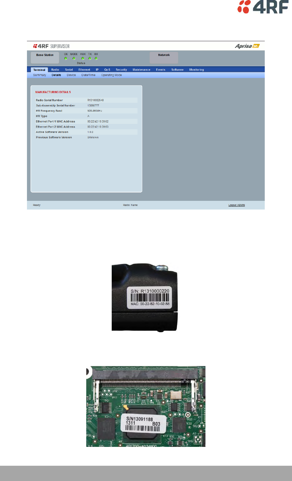
80 | Managing the Radio
Aprisa SRi User Manual 1.0.0
Terminal > Details
MANUFACTURING DETAILS
Radio Serial Number
This parameter displays the Serial Number of the radio (shown on the enclosure label).
Sub-Assembly Serial Number
This parameter displays the Serial Number of the printed circuit board assembly (shown on the PCB label).

Managing the Radio | 81
Aprisa SRi User Manual 1.0.0
HW Frequency Band
This parameter displays the hardware radio frequency operating range.
HW Type
This parameter displays the hardware board assembly type.
Radio MAC Address
This parameter displays the MAC address of the radio (the management Ethernet MAC address).
Active Software Version
This parameter displays the version of the software currently operating the radio.
Previous Software Version
This parameter displays the software version that was running on the radio prior to the current software
being activated.
A new radio from the factory will display ‘None’ for the Previous SW Version.
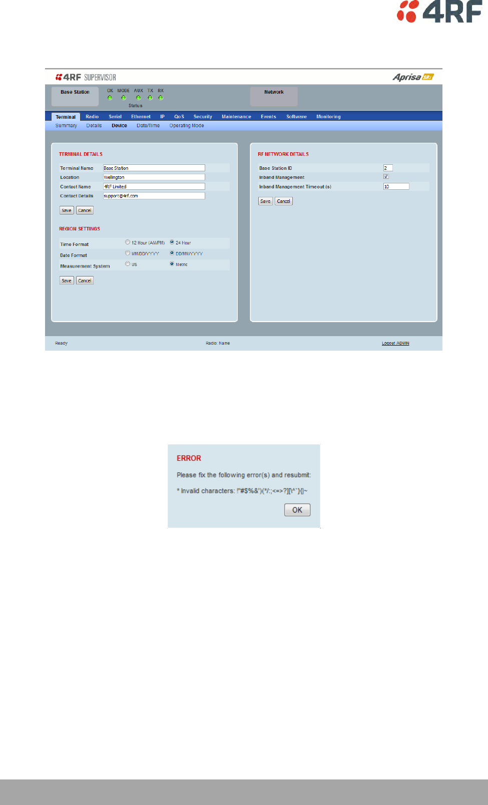
82 | Managing the Radio
Aprisa SRi User Manual 1.0.0
Terminal > Device
TERMINAL DETAILS
The data entry in the next four fields can be up to 40 characters but cannot contain invalid characters. A
popup warns of the invalid characters:
1. Enter the Terminal Name.
2. Enter the Location of the radio.
3. Enter a Contact Name. The default value is ‘4RF Limited’.
4. Enter the Contact Details. The default value is ‘support@4RF.com’.

Managing the Radio | 83
Aprisa SRi User Manual 1.0.0
RF NETWORK DETAILS
Network ID
This parameter sets the network ID of this base station node and its remote stations in the network. The
entry is four hexadecimal chars (not case sensitive).
The default setting is CAFE.
Base Station ID
This parameter identifies the base station. All radios operating to the base station in the same network
must use the same Base Station ID setting.
It is especially important to set different values for each network when two or more networks using the
same frequencies are operating with some overlapping coverage. The entry is an integer from 1 to 8.
Inband Management
This parameter sets the Inband Management option.
If the Inband Management option is enabled, SuperVisor operating on a base station can also manage all
the remote stations in the network.
Inband Management Timeout (sec)
This parameter sets the Inband Management timeout period. This determines the time the base station
waits for a response from a remote before aborting the Inband Management request. The default setting is
10 seconds.
REGION SETTINGS
Time Format
This parameter sets the time format for all time based results.
The default setting is 24 Hours.
Date Format
This parameter sets the date format for date based results.
The default setting is DD/MM/YYYY.
Measurement System
This parameter sets the unit type for parameters like temperature readings.
The default setting is Metric.
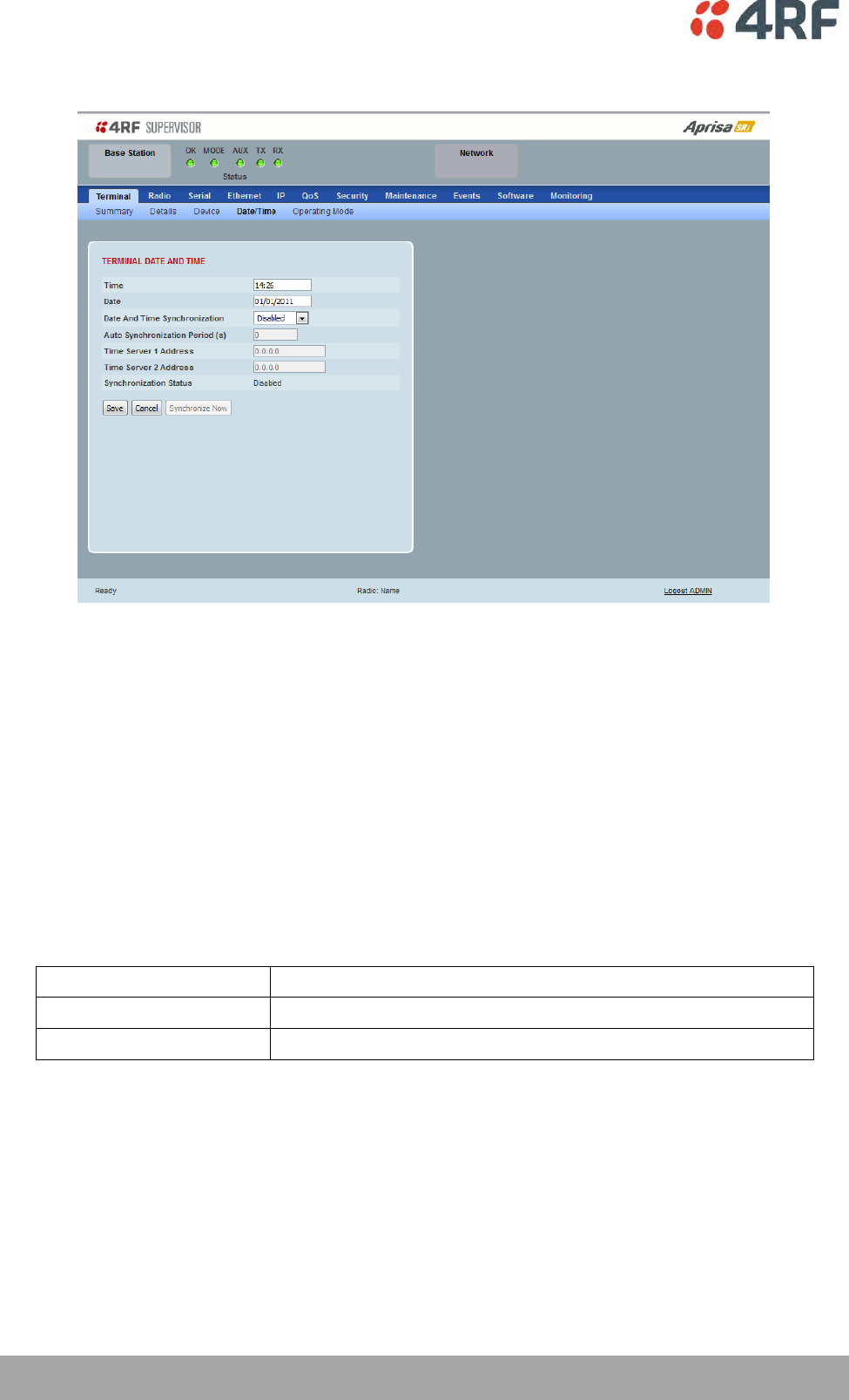
84 | Managing the Radio
Aprisa SRi User Manual 1.0.0
Terminal > Date / Time
TERMINAL DATE AND TIME
Sets the Time and Date. This information is controlled from a software clock.
Date and Time Synchronization
This Date and Time Synchronization feature allows a radio to synchronize its date and time from an SNTP
server. It would predominantly be used on the base station but could be used on a remote station.
Using the SNTP feature will ensure that all radios in the network has the same date and time required for
accurate network diagnostics.
For high availability time/date synchronization, SNTP can be synchronized from two SNTP servers for
server backup.
The default setting is Disabled.
Option
Function
Disabled
No SNTP Date and Time Synchronization
SNTP
Date and Time will be synchronized to a SNTP server
The base station periodically sends a broadcast message to the remote stations to synchronize the radio
date and time.

Managing the Radio | 85
Aprisa SRi User Manual 1.0.0
Auto Synchronization Period (s)
This parameter sets the number of seconds between the end of the last synchronization and the next
synchronization attempt. The minimum period is 60 seconds. A period of 0 seconds will disable
synchronization attempts.
Time Server 1 Address
This parameter sets the IP address of the first priority SNTP server. If the synchronization is successful to
this server, Time Server 2 Address will not be used.
Time Server 2 Address
This parameter sets the IP address of the second priority SNTP server. If the synchronization fails using the
SNTP server on Time Server 1 Address, synchronization will be attempted to the SNTP server on this
address.
Synchronization Status
This field shows the status of the current synchronization or the result of the last synchronization.
Synchronize Now
This Synchronize Now button provides manual Synchronization.
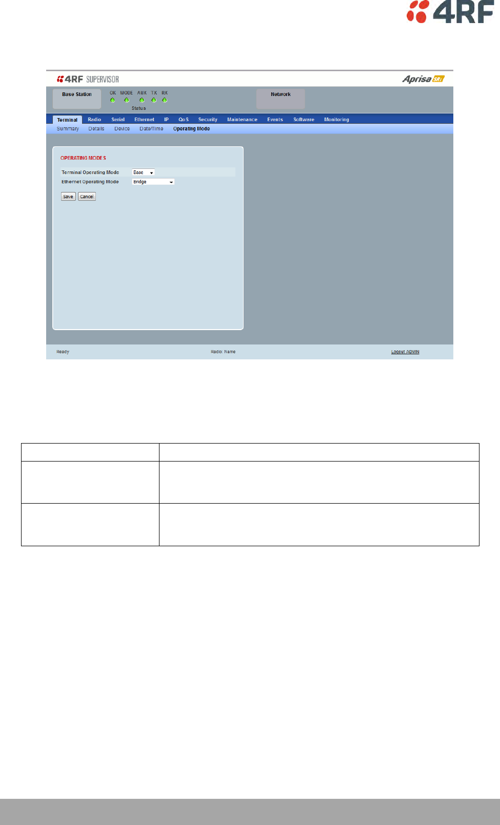
86 | Managing the Radio
Aprisa SRi User Manual 1.0.0
Terminal > Operating Mode
OPERATING MODES
Terminal Operating Mode
The default setting is Remote.
Option
Function
Base
The base station manages all traffic activity between itself and
remotes. It is the center-point of the network where in most cases
will be connected to a SCADA master.
Remote
The remote in most cases is used as the end-point of the SCADA
network connected to an RTU or PLC device for SCADA network
control and monitoring.

Managing the Radio | 87
Aprisa SRi User Manual 1.0.0
Ethernet Operating Mode
The Ethernet Operating Mode defines how Ethernet / IP traffic is processed in the radio. The default
setting is Bridge.
Option
Function
Bridge
Bridge mode inspects each incoming Ethernet frame source and
destination MAC addresses to determine if the frame is forwarded
over the radio link or discarded.
Gateway Router
Gateway Router mode inspects each incoming IP source and
destination IP addresses to determine if the packet is forwarded
over the radio link or discarded. In this mode, all Ethernet
interfaces have the same IP address and subnet.
Router
Router mode inspects each incoming IP source and destination IP
addresses to determine if the packet is forwarded over the radio
link or discarded. In this mode, each Ethernet interface has a
different IP address and subnet.

88 | Managing the Radio
Aprisa SRi User Manual 1.0.0
TERMINAL PROTECTION
Protection Type
The Protection Type defines if a radio is a stand-alone radio or part of an Aprisa SRi Protected Station.
The default setting is None.
Option
Function
None
The SRi radio is stand-alone radio (not part of an Aprisa SRi
Protected Station).
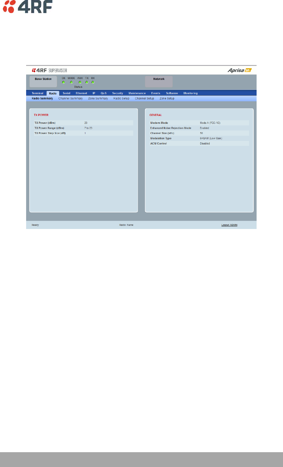
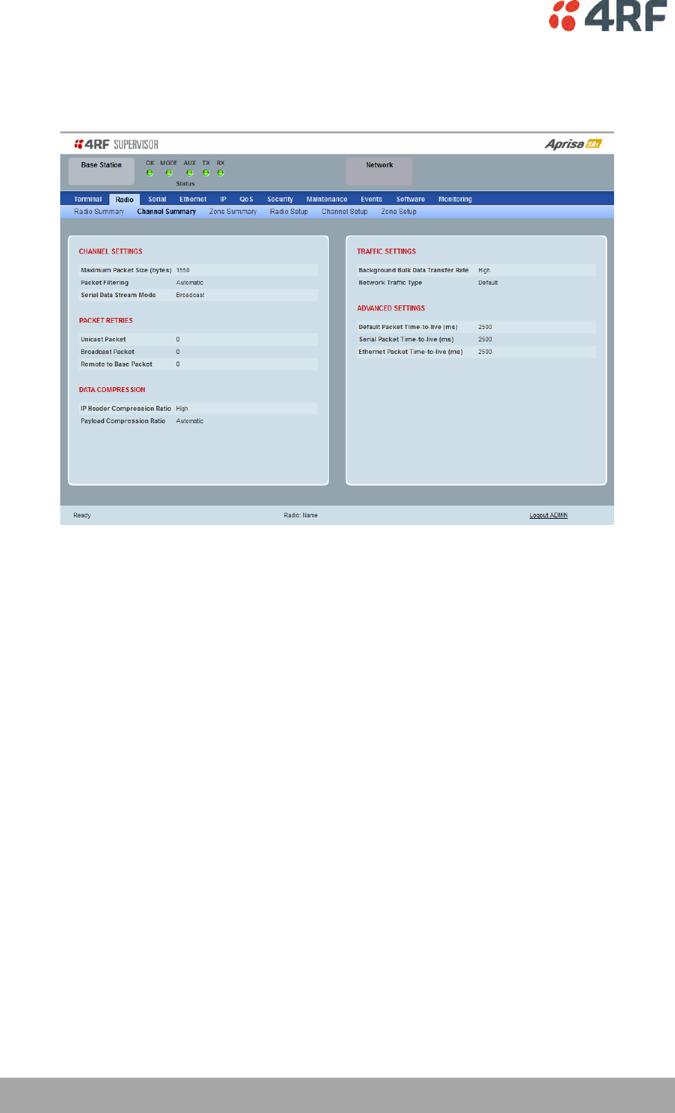
90 | Managing the Radio
Aprisa SRi User Manual 1.0.0
Radio > Channel Summary
This page displays the current settings for the Channel parameters.
See ‘Radio > Channel Setup’ for setting details.
DATA COMPRESSION
Payload Compression Ratio
The payload is compressed using level 3 QuickLZ data compression. Payload Compression is automatic and
cannot be turned off by SuperVisor.
Compression is not attempted on data that is already compressed e.g. jpg files.
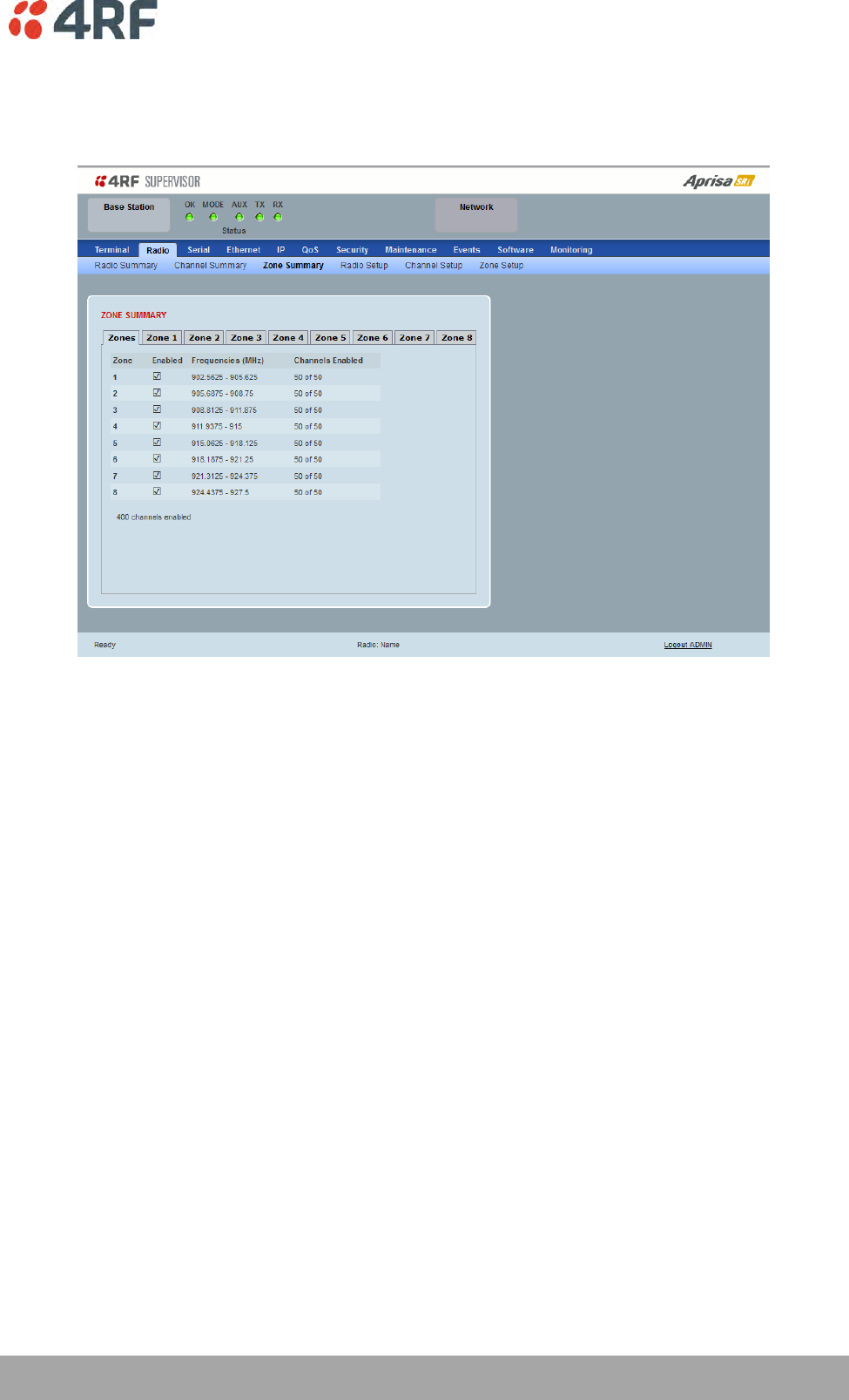
Managing the Radio | 91
Aprisa SRi User Manual 1.0.0
Radio > Zone Summary
This page displays the current settings for the Zones.
See ‘Radio > Channel Setup’ for setting details.
ZONE SUMMARY
Zone
The zone number defined in the regulatory specification. The maximum number of standard hop zones is
8.
Enabled
Displays the hop zones enabled.
Frequencies
Displays the zone frequencies defined for the zone hop number.
Channels Enabled
Displays the number of channels selected in the zone.
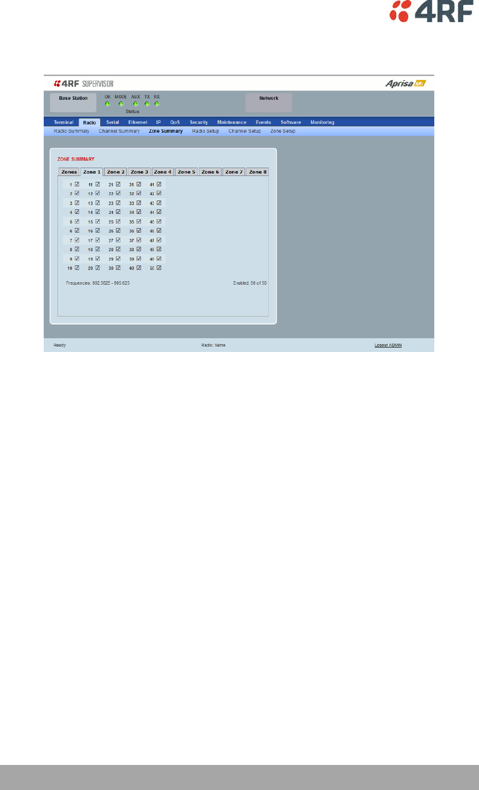
92 | Managing the Radio
Aprisa SRi User Manual 1.0.0
The Zone Summary > Zones shows the channels enabled per zone hop 1 to 8.
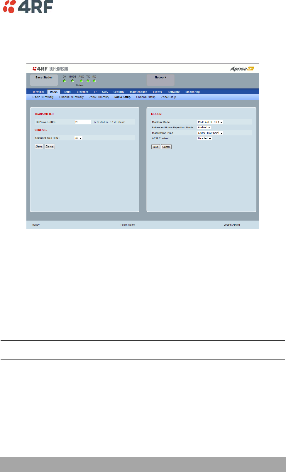
Managing the Radio | 93
Aprisa SRi User Manual 1.0.0
Radio > Radio Setup
Transmit frequency, maximum transmit power and channel size would normally be defined by a local
regulatory body.
TRANSMITTER
TX Power
The transmitter power is the power measured at the antenna output port when transmitting. The
transmitter power has a direct impact on the radio power consumption. The default setting is +26 dBm.
The maximum permitted transmitter power may be limited by the EIRP requirements. See ‘Compliance
Considerations’ on page 46 for details.
If TX Power setting is higher than the high limit or lower than the low limit for the current modulation, an
Informational Event (55 Terminal Unit Information) will be raised to notify the user that transmit power
has been changed. This only applies to fixed modulation (not ACM).
Note: The Aprisa SRi transmitter contains power amplifier protection which allows the antenna to be
disconnected from the antenna port without product damage.
GENERAL
Channel Size (kHz)
This parameter sets the Channel Size for the radio (see ‘Channel Sizes’ on page 279 for Radio Capacities).
The default setting is 50 kHz.
94 | Managing the Radio
Aprisa SRi User Manual 1.0.0
MODEM
Modem Mode
This parameter sets the Modem Mode in the radio. The Modem Mode option list is dependent on the radio
Hardware Variant (defined by the part number ordered).
HW Variant
Option
Channel Sizes
915 MHz
Mode A (FCC)
50 kHz
Enhanced Noise Rejection Mode
This parameter enables / disables the Enhanced Noise Rejection Mode in the radio. This feature improves
co-channel interference performance at strong receiver signal levels. All radios in an Aprisa SRi network
must use the same setting i.e. enabled or disabled.
The default setting is Enabled.
Modulation Type
The remote to base direction of transmission is always fixed i.e. not adaptive.
This parameter sets the fixed TX Modulation Type for the base to remote direction.
Option
Function
QPSK (Low Gain)
Sets the modulation to QPSK with Min Coded FEC.
16QAM (Low Gain)
Sets the modulation to 16 QAM with Min Coded FEC.
64QAM (Low Gain)
Sets the modulation to 64 QAM with Min Coded FEC.
The default setting is QPSK (Low Gain).
The base station radio TX modulation will be set based on the worse case (RSSI) path profile scenario of all
the radios in one hop distance from the base station radio.

Managing the Radio | 95
Aprisa SRi User Manual 1.0.0
ACM Control (base station)
This parameter enables / disables Adaptive Code Modulation for the remote to base direction of
transmission (upstream).
When ACM is enabled, the base station sends a modulation type recommendation to each remote radio
based on the signal quality for each individual remote radio.
Option
Function
Disabled
Disables Adaptive Code Modulation for the upstream.
The base station does not send a modulation type recommendation
to any remote radio.
Standard
Enables Adaptive Code Modulation for the upstream.
The ACM will be selected based on the link quality.
The default setting is Standard.

96 | Managing the Radio
Aprisa SRi User Manual 1.0.0
ACM Control (remote station)
These settings are only used if the Modulation Type is set to Adaptive and only apply to the remote to
base direction of transmission (upstream).
The remote to base direction of transmission can be adaptive modulation or fixed modulation.
This parameter sets the TX Modulation Type for the remote station radio.
Option
Function
Adaptive
Sets the modulation type to Adaptive Code Modulation.
The remote radio receives the modulation type recommendation
from the base and adjusts the modulation and FEC code rate in the
remote to base direction of transmission (upstream).
QPSK (Low Gain)
Sets the modulation to QPSK with Min Coded FEC.
16QAM (Low Gain)
Sets the modulation to 16 QAM with Min Coded FEC.
64QAM (Low Gain)
Sets the modulation to 64 QAM with Min Coded FEC.
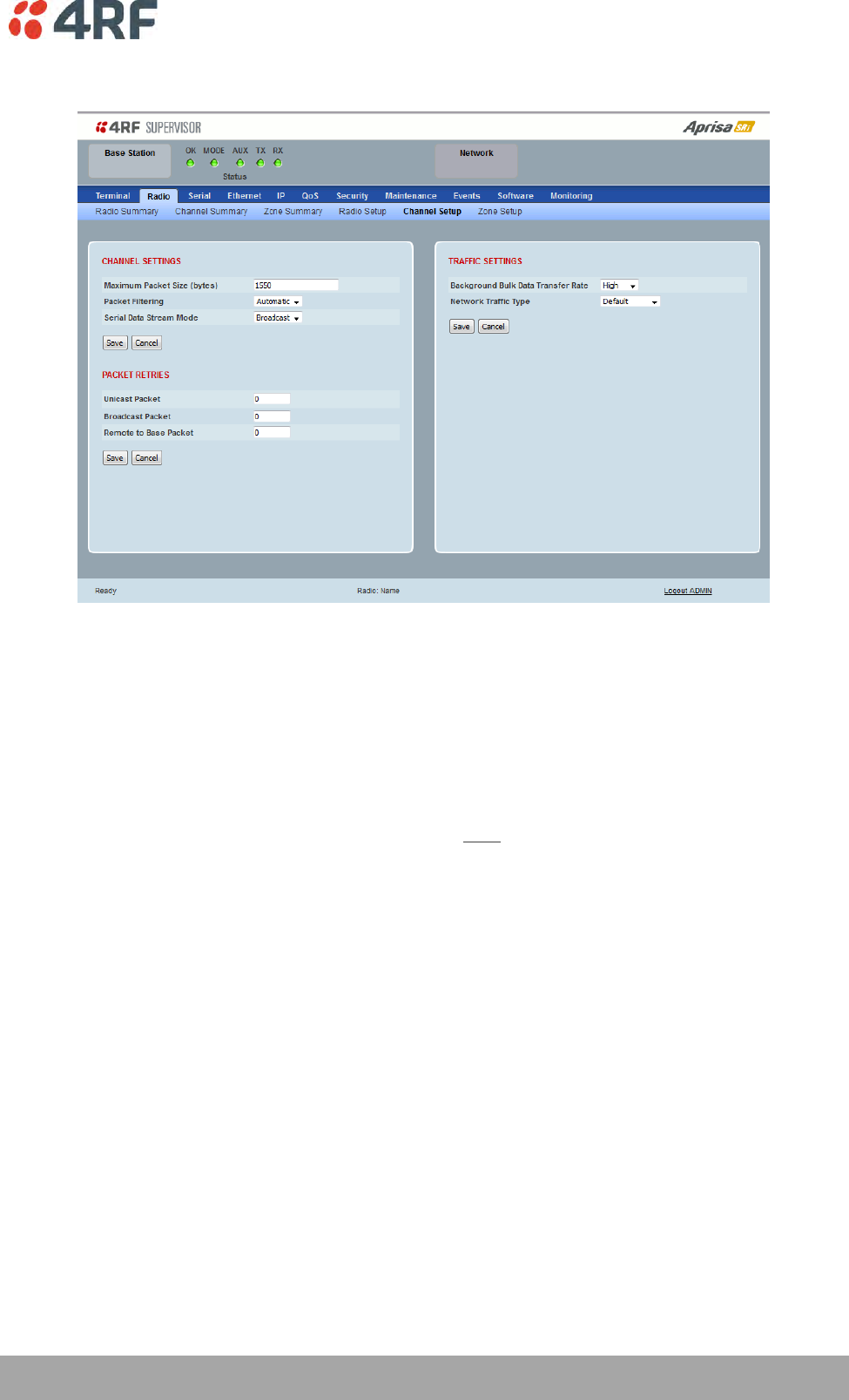
Managing the Radio | 97
Aprisa SRi User Manual 1.0.0
Radio > Channel Setup
CHANNEL SETTINGS
Maximum Packet Size (Bytes)
This parameter sets the maximum over-the-air packet size in bytes. A smaller maximum Packet Size is
beneficial when many remote stations are trying to access the channel. The default setting is 1550 bytes.
As radios dispatched from the factory have a Packet Size set to the maximum value of 1550 bytes, if a new
radio is installed in an existing network, the Packet Size must be changed to ensure it is the same value
for all radios in the network. The new radio will not register an existing network if the Packet Size is not
the same as the other radios in the network.
This packet size includes the wireless protocol header and security payload (0 to 16 bytes). The length of
the security header depends on the level of security selected.
When the security setting is 0, the maximum user data transfer over-the-air is 1516 bytes.
When encryption is enabled, the entire packet of user data (payload) is encrypted. If authentication is
being used, the security frame will be added (up to 16 bytes). The wireless protocol header is then added
which is proprietary to the Aprisa SRi. This is not encrypted.
98 | Managing the Radio
Aprisa SRi User Manual 1.0.0
Packet Filtering
Each Aprisa SRi radio can filter packets not destined for itself. The Packet Filtering parameter controls
this functionality.
In an Aprisa SRi network, all communication from remote stations is destined for the base station in the
Aprisa SRi network communication protocol.
Option
Function
Disabled
Every packet received by the radio will be forwarded to the
relevant interface.
Automatic
The radio will filter (discard) packets not destined for itself
according to the Aprisa SRi traffic protocols
The default setting is Automatic.
Note: The Aprisa SRi network is transparent to the protocol being transmitted; therefore the Packet
Filtering parameter is based on the Aprisa SRi addressing and network protocols, not the user (SCADA,
etc.) traffic protocols.
Serial Data Stream Mode
This parameter controls the traffic flow in the radio serial ports.
Option
Function
Broadcast
Serial port traffic from the network is broadcast on all serial ports
on this radio. This will include the RS-232 port derived from the
USB port.
Segregate
Serial port traffic from the network from a specific port number is
directed to the respective serial port only (see Segregated Port
Directions).
The default setting is Broadcast.

Managing the Radio | 99
Aprisa SRi User Manual 1.0.0
PACKET RETRIES
The larger the number of retries, the greater the chance the packet will be delivered but reduces overall
packet throughput.
Unicast Packet
Sets the number of unicast packet retries for the radio.
Base Station
The base station unicast packet retries sets the number of retries for a packet sent to remote radios.
Remote Radios
The remote radio unicast packet sets the number of retries for a packet sent to the base station.
If the Auto is ticked, remote radios will use the unicast packet retries setting sent from the base station
If the Auto is unticked, remote radios will use the unicast packet retries set on the remote radio.
Broadcast Packet
The base station broadcast packet retries sets the number of broadcast packet retries for packets sent to
all remote radios.
Remote To Base Packet
Sets all remote radio unicast packet retries setting if the remote radio unicast packet Auto is ticked.
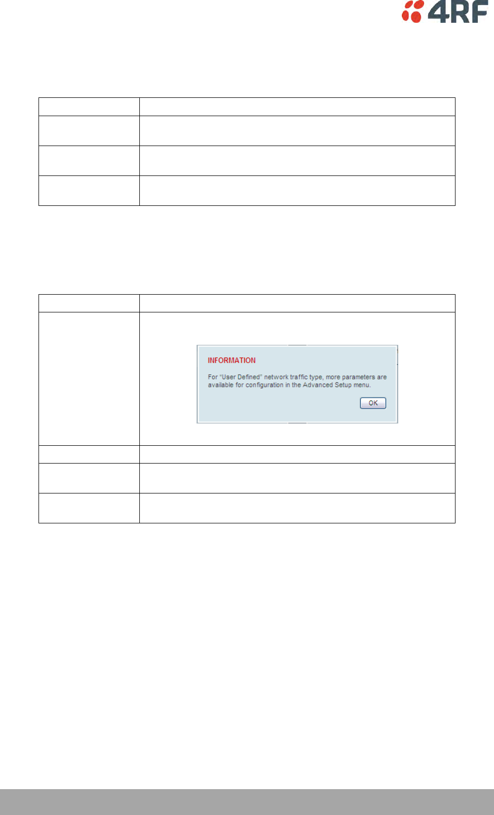
100 | Managing the Radio
Aprisa SRi User Manual 1.0.0
TRAFFIC SETTINGS
Background Bulk Data Transfer Rate
This parameter sets the data transfer rate for large amounts of management data.
Option
Function
High
Utilizes more of the available capacity for large amounts of
management data. Highest impact on user traffic.
Medium
Utilizes a moderate of the available capacity for large amounts of
management data. Medium impact on user traffic.
Low
Utilizes a minimal of the available capacity for large amounts of
management data. Lowest impact on user traffic.
The default setting is high.
Network Traffic Type
This parameter optimizes the channel settings for the predominant traffic type.
Option
Function
User Defined
Allows the user to define the channel settings (see ‘Radio >
Advanced Setup’ on page 104).
Serial Only
Optimizes the channel settings for the predominantly serial traffic.
Ethernet Only
Optimizes the channel settings for the predominantly Ethernet
traffic.
Mixed
Optimizes the channel settings for a mix of Ethernet and serial
traffic.
The default setting is Mixed.
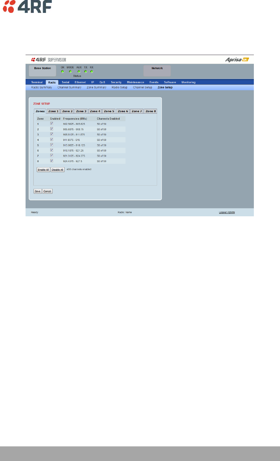
Managing the Radio | 101
Aprisa SRi User Manual 1.0.0
Radio > Zone Setup
This page configures the Zone / Channel settings.
ZONE SETUP
Specific channels within the selected zone hop can be disabled if there is a known transmission within the
channel that may cause interference to the operation of this network. The minimum number of enabled
channels is 50.
Initially, remote radio channels are enabled to allow communication with the base station.
When a remote radio registers with the base station, the remote radio will automatically configure to use
the zone channel list distributed by the base station. The zone channels displayed on the remote radio will
continue to display the radio channels initially enabled (not the zone channel list distributed by the base
station).
Zone
The zone number from 1 to 8.
Enabled
Enables / disables the entire hop zone of channels. If a channel is selected in a zone that is disabled, the
zone will be enabled when the channel selection is saved. The default is all zones enabled.

102 | Managing the Radio
Aprisa SRi User Manual 1.0.0
Frequencies
The zone frequencies are pre-defined in the Aprisa SRi for the zone number. The zone frequencies are
spaced at the hop frequency of 62.5 kHz.
Channels Enabled
Displays the number of channels selected in the zone.
Controls
The Enable All button enables all zones and all channels in each zone.
The Disable All button disables all zones and all channels in each zone.
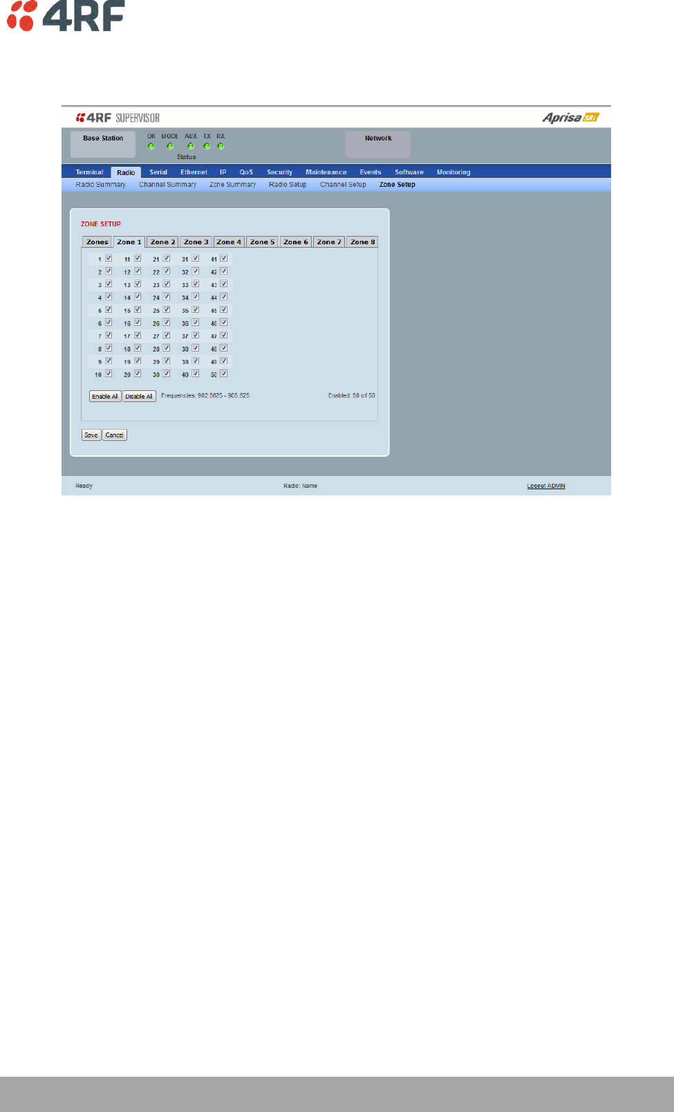
Managing the Radio | 103
Aprisa SRi User Manual 1.0.0
The Zone Setup > Zones 1 to 8 setup the channels per zone hop.
ZONE SETUP
Specific channels within the selected zone hop can be disabled if there is a known transmission within the
channel that may cause interference to the operation of this network. The minimum number of enabled
channels is 50.
Initially, remote radio channels are enabled to allow communication with the base station.
When a remote radio registers with the base station, the remote radio will automatically configure to use
the zone channel list distributed by the base station. The zone channels displayed on the remote radio will
continue to display the radio channels initially enabled (not the zone channel list distributed by the base
station).
Controls
The Enable All button enables all channels in the zone.
The disable All button disables all channels in the zone.
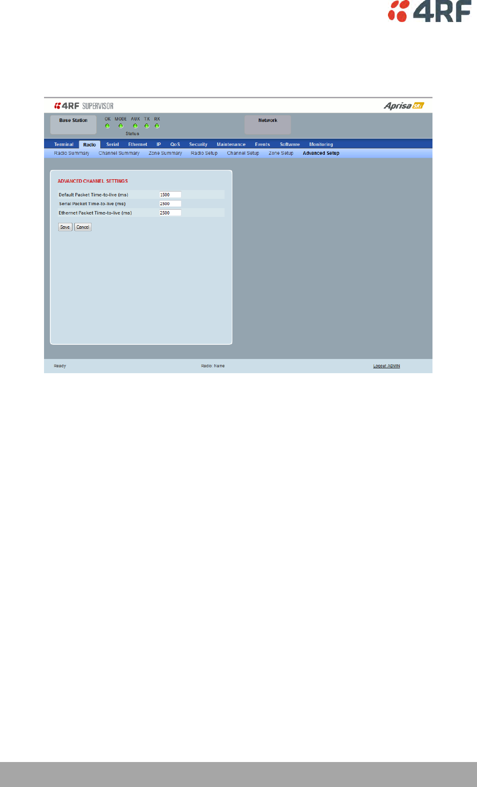
104 | Managing the Radio
Aprisa SRi User Manual 1.0.0
Radio > Advanced Setup
This page is only visible when the Channel Setup > Network Traffic Type is set to User Defined.
ADVANCED CHANNEL SETTINGS
Default Packet Time to Live (ms)
This parameter sets the default time a packet is allowed to live in the system before being dropped if it
cannot be transmitted over the air. It is used to prevent old, redundant packets being transmitted through
the Aprisa SRi network. The default setting is 1500 ms.
In the case of serial poll SCADA networks such as MODBUS and IEC 60870.50.101, it is important to ensure
the replies from the RTU are in the correct sequence and are not timed out replies from Master requests.
If the TTL value is too long, the SCADA master will detect sequence errors.
It is recommended to use a TTL which is half the serial SCADA timeout. This is commonly called the ‘scan
timeout’ or ‘link layer time out’ or ‘retry timeout’.
When using TCP protocols, a TTL of 1500 ms is recommended because a TCP re-transmission usually occurs
after approximately 3 seconds.
In SCADA networks which use both serial and Ethernet, it is recommended that the TTL is set to half the
serial SCADA timeout for serial remotes, and 1500 ms for Ethernet (TCP) remotes. For example, if the
serial SCADA timeout is 1000 ms, a remote radio which is connected to the serial RTU should be set to
500 ms, a remote radio which is connected to an Ethernet (TCP) RTU should have a 1500 ms timeout.
In this case, the base station TTL should be set to 1500 ms as well; or whichever is the longer TTL of serial
or Ethernet.

Managing the Radio | 105
Aprisa SRi User Manual 1.0.0
Serial Packet Time to Live (ms)
This parameter sets the time a serial packet is allowed to live in the system before being dropped if it
cannot be transmitted over the air. The default setting is 800 ms.
Ethernet Packet Time to Live (ms)
This parameter sets the time an Ethernet packet is allowed to live in the system before being dropped if it
cannot be transmitted over the air. The default setting is 600 ms.
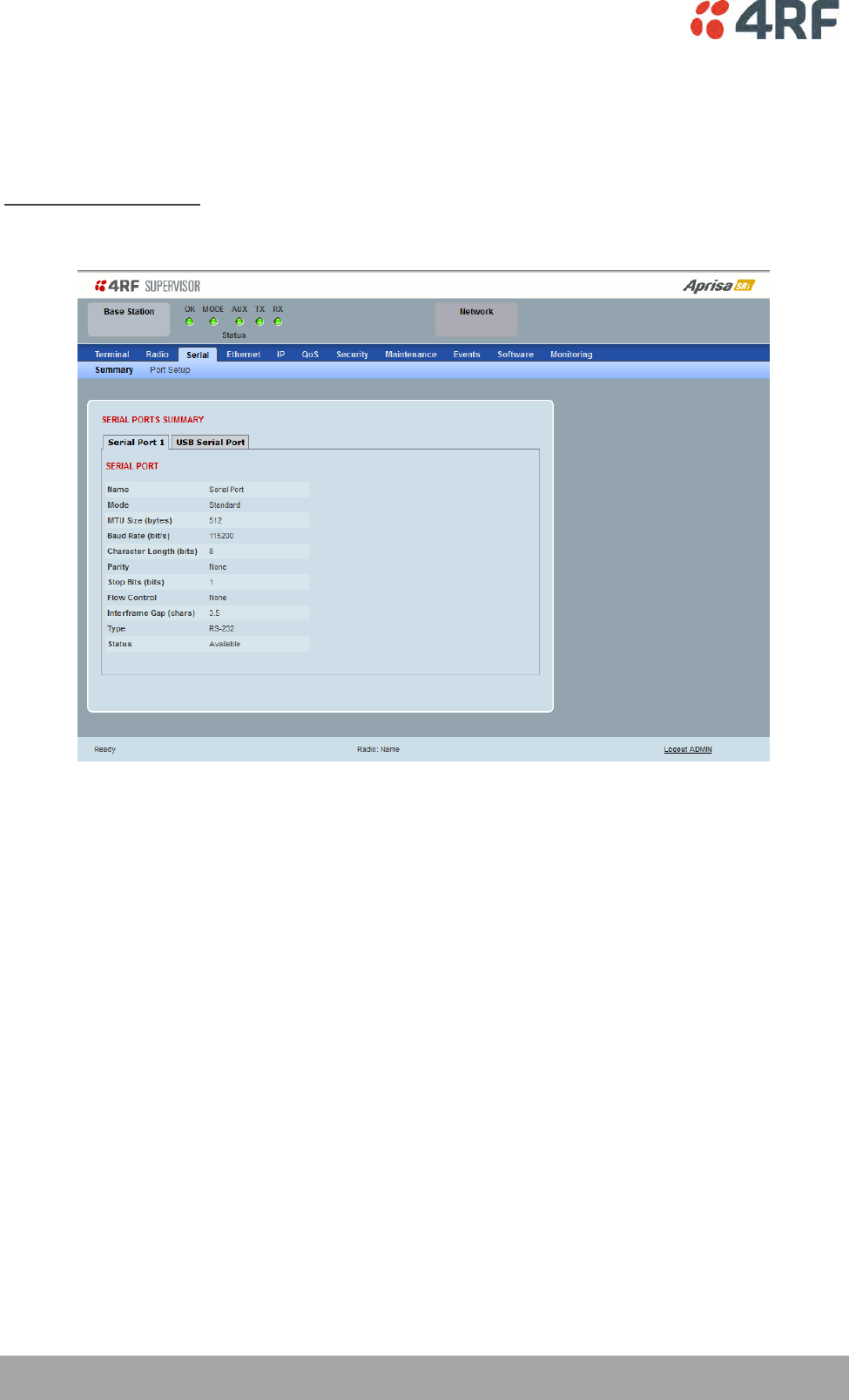
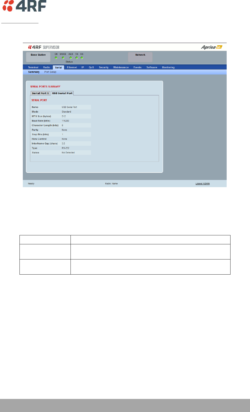
Managing the Radio | 107
Aprisa SRi User Manual 1.0.0
USB Serial Ports
This page displays the current settings for the USB serial port parameters.
Type
This parameter displays the Serial Port interface type.
If the Name is USB Serial Port:
Option
Function
RS-232
Indicates that a USB to RS-232 serial converter is plugged into the
radio.
RS-485
Indicates that a USB to RS-485 serial converter is plugged into the
radio.
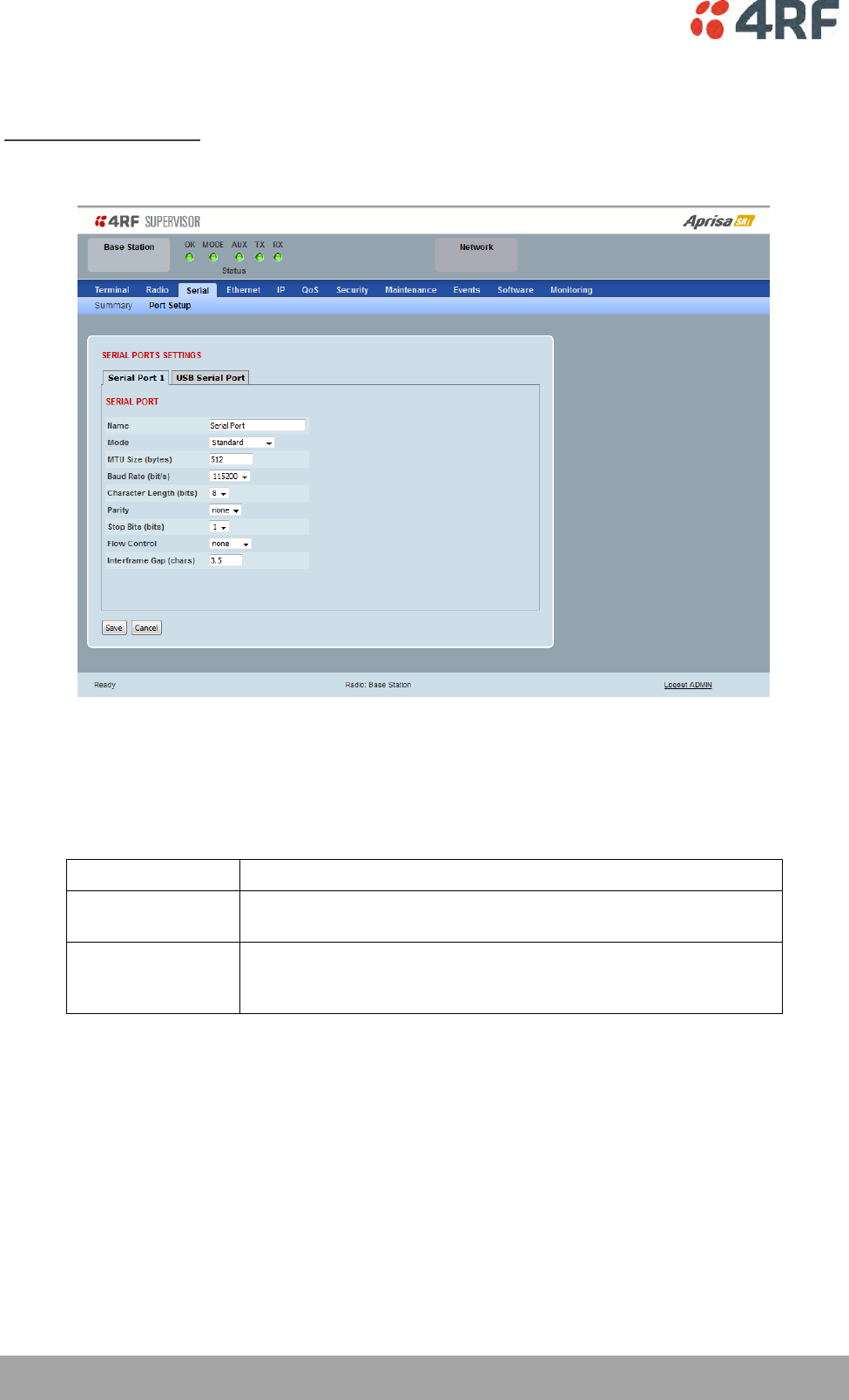
108 | Managing the Radio
Aprisa SRi User Manual 1.0.0
Serial > Port Setup
RS-232 Hardware Ports
This page provides the setup for the serial port settings.
SERIAL PORTS SETTINGS
Name
This parameter sets the port name which can be up to 32 characters.
Option
Function
Serial Port
This is the normal RS-232 serial ports provided with the RJ45
connector.
USB Serial Port
This is the optional RS-232 / RS-485 serial port provided with the
USB host port connector with a USB to RS-232 / RS-485 RJ45
converter cable (see ‘USB Serial Ports’ on page 261).

Managing the Radio | 109
Aprisa SRi User Manual 1.0.0
Mode
This parameter defines the mode of operation of the serial port. The default setting is Standard.
Option
Function
Disabled
The serial port is not required.
Standard
The serial port is communicating with serial ports on other
stations.
Terminal Server
A base station Ethernet port can communicate with both Ethernet
ports and serial ports on remote stations.
RS-232 traffic is encapsulated in IP packets (see ‘Serial > Port
Setup’ Terminal Server on page 111).
SLIP
IP packets are encapsulated over RS-232 interface port (see ‘Serial
> Port Setup’ Serial Line Interface Protocol (SLIP)’ on page 113).
MTU Size (bytes)
This parameter sets the size of the packet in bytes received before it is transmitted if an inter-frame gap
is not detected. The default setting is 512 bytes.
Baud Rate (bit/s)
This parameter sets the baud rate to 300, 600, 1200, 2400, 4800, 9600, 19200, 38400, 57600 or 115200
bit/s. The default setting is 115200 bit/s.
Character Length (bits)
This parameter sets the character length to 7 or 8 bits. The default setting is 8 bits.
Parity
This parameter sets the parity to Even, Odd or None. The default setting is None.
Stop Bits (bits)
This parameter sets the number of stop bits to 1 or 2 bits. The default setting is 1 bit.

110 | Managing the Radio
Aprisa SRi User Manual 1.0.0
Flow Control
This parameter sets the flow control of the serial port. The default setting is Disabled.
Option
Function
None
The Aprisa SRi radio port (DCE) CTS is in a permanent ON (+ve)
state.
This does not go to OFF if the radio link fails.
CTS-RTS
CTS / RTS hardware flow control between the DTE and the Aprisa
SRi radio port (DCE) is enabled.
If the Aprisa SRi buffer is full, the CTS goes OFF.
In the case of radio link failure the signal goes to OFF (-ve) state.
In terminal server mode, the serial packet is no different from an Ethernet packet and travels through
various packet queues before being transmitted over the air. Thus, the serial flow control has no affect in
terminal server mode.
Inter-Frame Gap (chars)
This parameter defines the gap between successive serial data frames. It is used to delimit the serial data
to define the end of a packet. The Inter-Frame Gap limits are 0 to 20 chars in steps of 0.1 char. The
default setting is 3.5 chars.
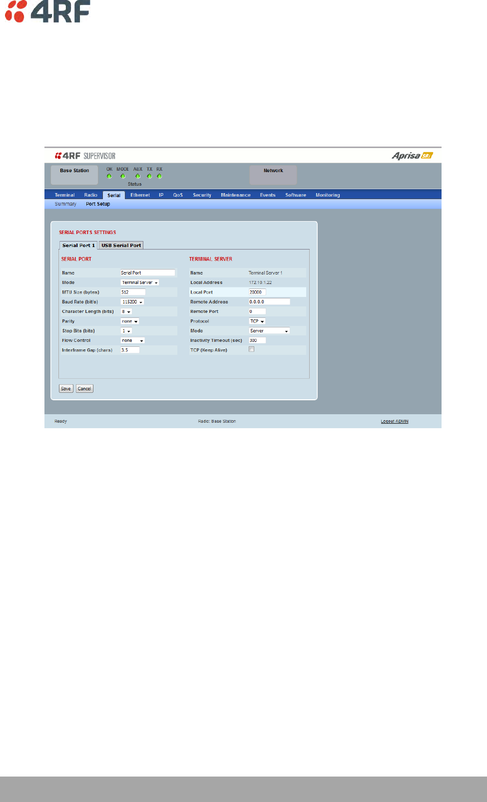
Managing the Radio | 111
Aprisa SRi User Manual 1.0.0
Terminal Server
This menu item is only applicable if the serial port has an operating mode of Terminal Server.
The Terminal Server operating mode provides encapsulation of serial data into an IP packet (over TCP or
UDP).
A server connected to a base station Ethernet port can communicate with all remote station Ethernet
ports and serial ports.
Local Address
This parameter displays the IP address of this radio.
Local Port
This parameter sets the TCP or UDP port number of the local serial port.
The valid port number range is greater than or equal to 1024 and less than or equal to 49151 but with
exclusions of 0, 5445, 6445, 9930 or 9931. The default setting is 20000.
Remote Address
This parameter sets the IP address of the server connected to the radio Ethernet port.
Remote Port
This parameter sets the TCP or UDP port number of the server connected to the radio Ethernet port. The
default setting is 0.

112 | Managing the Radio
Aprisa SRi User Manual 1.0.0
Protocol
This parameter sets the L4 TCP/IP or UDP/IP protocol used for terminal server operation. The default
setting is TCP.
Mode
This parameter defines the mode of operation of the terminal server connection. The default setting is
Client and Server.
Option
Function
Client
The radio will attempt to establish a TCP connection with the
specified remote unit. Generally, this setting is for the base station
with an Ethernet connection to the SCADA master.
Server
The radio will listen for a TCP connection on the specified local
port. Generally, this setting is for the remote station with a serial
connection to the RTU.
Data received from any client shall be forwarded to the associated
serial port while data received from that serial port shall be
forwarded to every client with an open TCP connection.
If no existing TCP connections exist, all data received from the
associated serial port shall be discarded.
Client and Server
The radio will listen for a TCP connection on the specified local
port and if necessary, establish a TCP connection with the
specified remote unit. Generally, this setting is used for the
remote station but it should be used carefully as two connections
might be established with the base station.
Data received from any client shall be forwarded to the associated
serial port while data received from that serial port shall be
forwarded to every client with an open TCP connection.
Inactivity Timeout (seconds)
This specifies the duration (in seconds) to automatically terminate the connection with the remote TCP
server if no data has been received from either the remote TCP server or its associated serial port for the
duration of the configured inactivity time.
TCP Keep Alive
A TCP keep alive is a message sent by one device to another to check that the link between the two is
operating, or to prevent the link from being broken.
If the TCP keep alive is enabled, the radio will be notified if the TCP connection fails.
If the TCP keep alive is disabled, the radio relies on the Inactivity Timeout to detect a TCP connection
failure. The default setting is disabled.
Note: An active TCP keep alive will generate a small amount of extra network traffic.
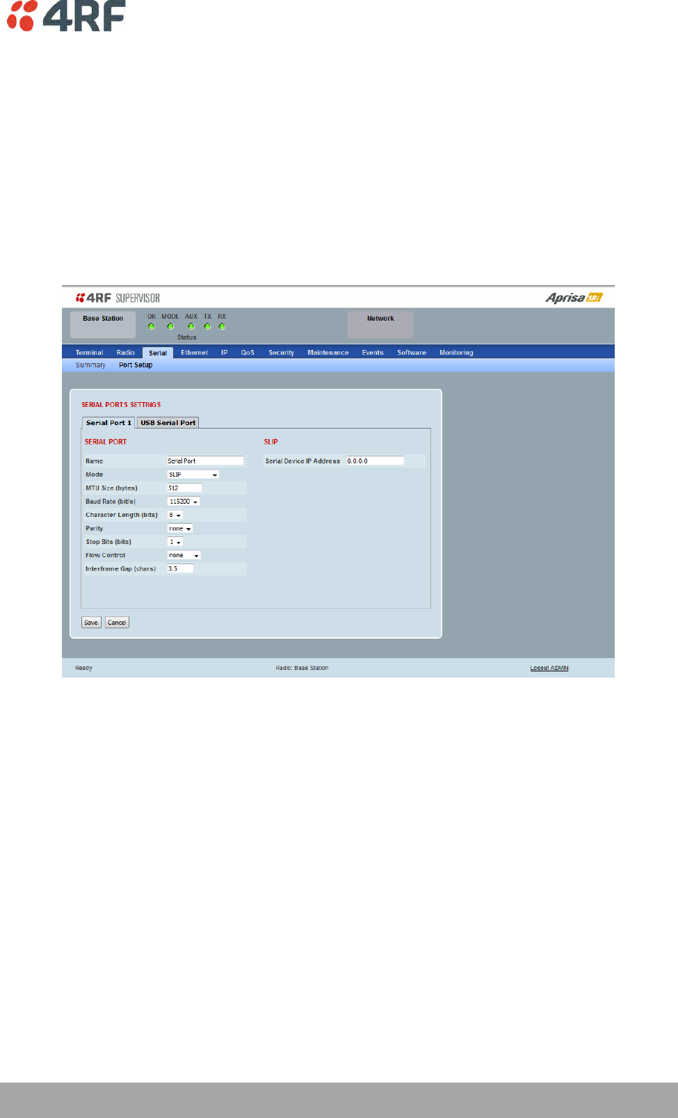
Managing the Radio | 113
Aprisa SRi User Manual 1.0.0
Serial Line Interface Protocol (SLIP)
This menu item is only applicable if the serial port has an operating mode of SLIP.
The SLIP operating mode provides IP packet encapsulation over RS-232 serial interface as per the SLIP
protocol RFC 1055.
A SLIP serial interface contains the IP address of the serially connected RTU as per the RTU/PLC SLIP
protocol. The SLIP interfaces on the remote radios can be part of the bridge network and can coexist and
operate with a mix of Ethernet interfaces, serial SLIP and terminal server interfaces.
As the RTU/PLC serial SLIP interface doesn't support MAC addresses, a remote radio SLIP interface uses a
proxy ARP function that returns its own MAC address for ARP requests based on the IP address of the
RTU/PLC SLIP interface.
Serial Device IP Address
This parameter sets the IP address of the RTU connected on the configured serial port.
Baud Rate (bit/s)
This parameter sets the baud rate to 1200, 2400, 4800, 9600, 19200, 38400, 57600 or 115200 bit/s. The
default setting is 115200 bit/s. The minimum supported baud rate is 1200 bit/s as SLIP will not work on
baud rates below 1200.
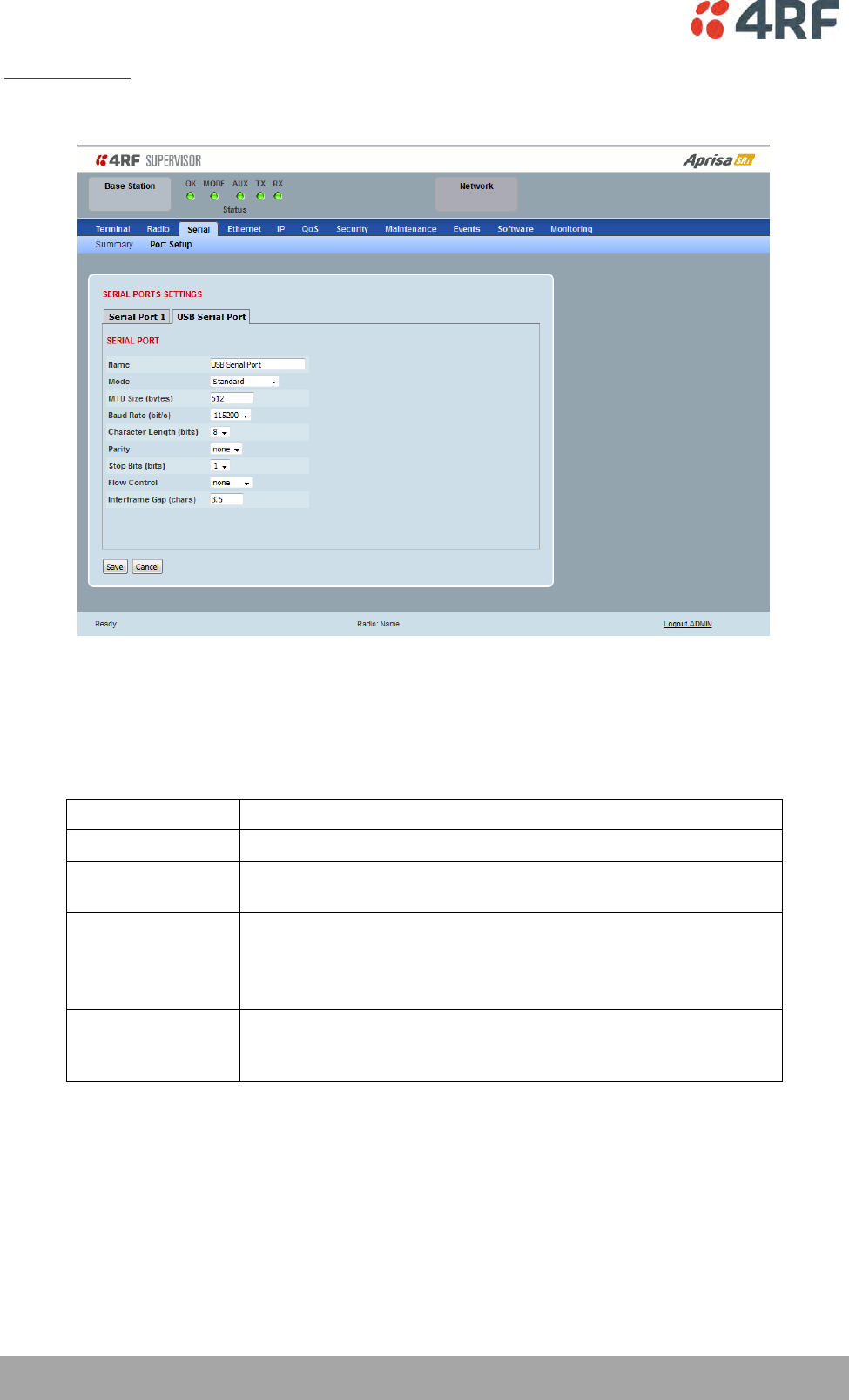
114 | Managing the Radio
Aprisa SRi User Manual 1.0.0
USB Serial Ports
This page provides the setup for the USB serial port settings.
SERIAL PORTS SETTINGS
Mode
This parameter defines the mode of operation of the serial port. The default setting is Disabled.
Option
Function
Disabled
The serial port is not required.
Standard
The serial port is communicating with serial ports on other
stations.
Terminal Server
A base station Ethernet port can communicate with both Ethernet
ports and serial ports on remote stations.
RS-232 traffic is encapsulated in IP packets (see ‘Serial > Port
Setup’ Terminal Server on page 111).
CLI Management
The USB host port is used to access the radio Command Line
Interface (CLI). A USB converter to RS-232 convertor will be
required to connect to a PC.
MTU Size (bytes)
This parameter sets the size of the packet in bytes received before it is transmitted if an inter-frame gap
is not detected. The default setting is 512 bytes.
Baud Rate (bit/s)
This parameter sets the baud rate to 300, 600, 1200, 2400, 4800, 9600, 19200, 38400, 57600 or 115200
bit/s. The default setting is 115200 bit/s.
Managing the Radio | 115
Aprisa SRi User Manual 1.0.0
Character Length (bits)
This parameter sets the character length to 7 or 8 bits. The default setting is 8 bits.
Parity
This parameter sets the parity to Even, Odd or None. The default setting is None.
Stop Bits (bits)
This parameter sets the number of stop bits to 1 or 2 bits. The default setting is 1 bit.
Flow Control
This parameter sets the flow control of the serial port. The default setting is Disabled.
Option
Function
None
The Aprisa SRi radio port (DCE) CTS is in a permanent ON (+ve)
state.
This does not go to OFF if the radio link fails.
CTS-RTS
CTS / RTS hardware flow control between the DTE and the Aprisa
SRi radio port (DCE) is enabled.
If the Aprisa SRi buffer is full, the CTS goes OFF.
In the case of radio link failure the signal goes to OFF (-ve) state.
In terminal server mode, the serial packet is no different from an Ethernet packet and travels through
various packet queues before being transmitted over the air. Thus, the serial flow control has no affect in
terminal server mode.
Inter-Frame Gap (chars)
This parameter defines the gap between successive serial data frames. It is used to delimit the serial data
to define the end of a packet. The Inter-Frame Gap limits are 0 to 20 chars in steps of 0.1 char. The
default setting is 3.5 chars.
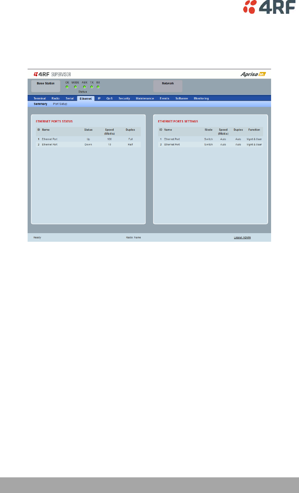
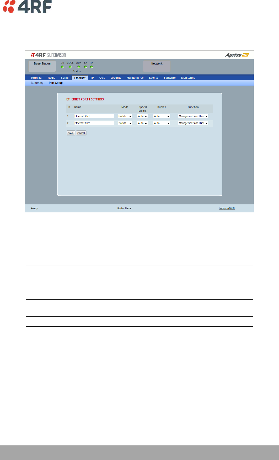
Managing the Radio | 117
Aprisa SRi User Manual 1.0.0
Ethernet > Port Setup
This page provides the setup for the Ethernet ports settings.
ETHERNET PORT SETTINGS
Mode
This parameter controls the Ethernet traffic flow. The default setting is Standard.
Option
Function
Standard
Enables Ethernet data communication over the radio link but
Ethernet traffic is not switched locally between the two
Ethernet ports.
Switch
Ethernet traffic is switched locally between the two
Ethernet ports and communicated over the radio link
Disabled
Disables all Ethernet data communications.
118 | Managing the Radio
Aprisa SRi User Manual 1.0.0
Speed (Mbit/s)
This parameter controls the traffic rate of the Ethernet port. The default setting is Auto.
Option
Function
Auto
Provides auto selection of Ethernet Port Speed
10/100 Mbit/s
10
The Ethernet Port Speed is manually set to 10 Mbit/s
100
The Ethernet Port Speed is manually set to 100 Mbit/s
Duplex
This parameter controls the transmission mode of the Ethernet port. The default setting is Auto.
Option
Function
Auto
Provides auto selection of Ethernet Port duplex setting.
Half Duplex
The Ethernet Port is manually set to Half Duplex.
Full Duplex
The Ethernet Port is manually set to Full Duplex.
Function
This parameter controls the use for the Ethernet port. The default setting is Management and User.
Option
Function
Management Only
The Ethernet port is only used for management of the
network.
Management and User
The Ethernet port is used for management of the network
and User traffic over the radio link.
User Only
The Ethernet port is only used for User traffic over the radio
link.
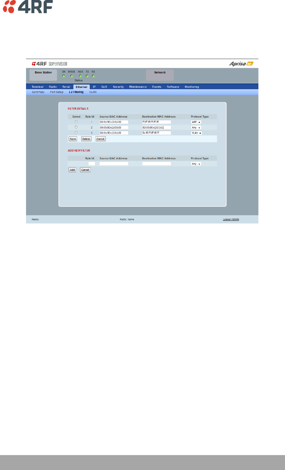
Managing the Radio | 119
Aprisa SRi User Manual 1.0.0
Ethernet > L2 Filtering
This page is only available if the Ethernet traffic option has been licensed (see ‘Maintenance > Licence’ on
page 191).
FILTER DETAILS
L2 Filtering provides the ability to filter (white list) radio link user traffic based on specified Layer 2 MAC
addresses.
User traffic originating from specified Source MAC Addresses destined for specified Destination MAC
Addresses that meets the protocol type criteria will be transmitted over the radio link.
User traffic that does not meet the filtering criteria will not be transmitted over the radio link.
Management traffic to the radio will never be blocked.
Source MAC Address
This parameter sets the filter to the Source MAC address of the packet in the format ‘hh:hh:hh:hh:hh:hh’.
If the Source MAC Address is set to ‘FF:FF:FF:FF:FF:FF’, traffic will be accepted from any source MAC
address.
Destination MAC Address
This parameter sets the filter to the Destination MAC address of the packet in the format
‘hh:hh:hh:hh:hh:hh’.
If the Destination MAC Address is set to ‘FF:FF:FF:FF:FF:FF’, traffic will be delivered to any destination
MAC address.
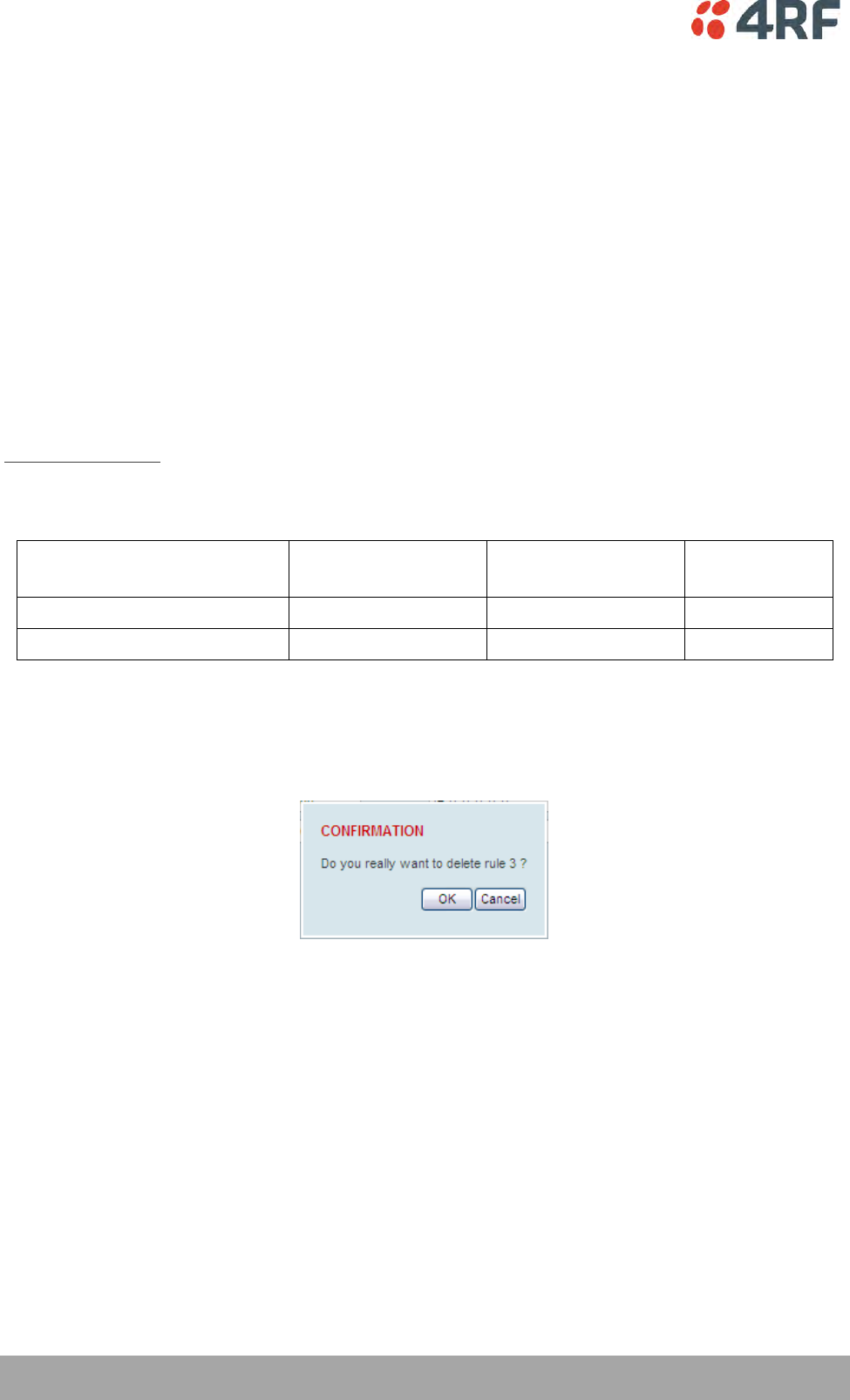
120 | Managing the Radio
Aprisa SRi User Manual 1.0.0
Protocol Type
This parameter sets the EtherType accepted ARP, VLAN, IPv4, IPv6 or Any type.
Example:
In the screen shot, the rules are configured in the base station which controls the Ethernet traffic to the
radio link.
Traffic from an external device with the Source MAC address 00:01:50:c2:01:00 is forwarded over the
radio link if it meets the criteria. All other traffic will be blocked.
Rule 1 If the Protocol Type is ARP going to any destination MAC address or
Rule 2 If the Protocol Type is Any and the destination MAC address is 01:00:50:c2:01:02 or
Rule 3 If the Protocol Type is VLAN tagged packets going to any unicast destination MAC address.
Special L2 Filtering Rules:
Unicast Only Traffic
This L2 filtering allows for Unicast only traffic and drop broadcast and multicast traffic. This filtering is
achieved by adding the two rules:
Rule
Source
MAC Address
Destination
MAC Address
Protocol Type
Allow ARPS
FF:FF:FF:FF:FF:FF
FF:FF:FF:FF:FF:FF
ARP
Allow Unicasts from Any source
FF:FF:FF:FF:FF:FF
FE:FF:FF:FF:FF:FF
Any
To delete a L2 Filter:
1. Click on an existing rule ‘Select’.
2. Click on Delete.
3. Click on OK.
ADD NEW FILTER
To add a L2 Filter:
1. Enter the Rule ID number. This is a unique rule number between 1 and 25.
2. Enter the Source MAC address of the packet or ‘FF:FF:FF:FF:FF:FF’ to accept traffic from any MAC
address.
3. Enter the Destination MAC address of the packet or ‘FF:FF:FF:FF:FF:FF’ to deliver traffic to any MAC
address.
4. Select the Protocol Type to ARP, VLAN, IPv4, IPv6 or Any type.
5. Click on Add.
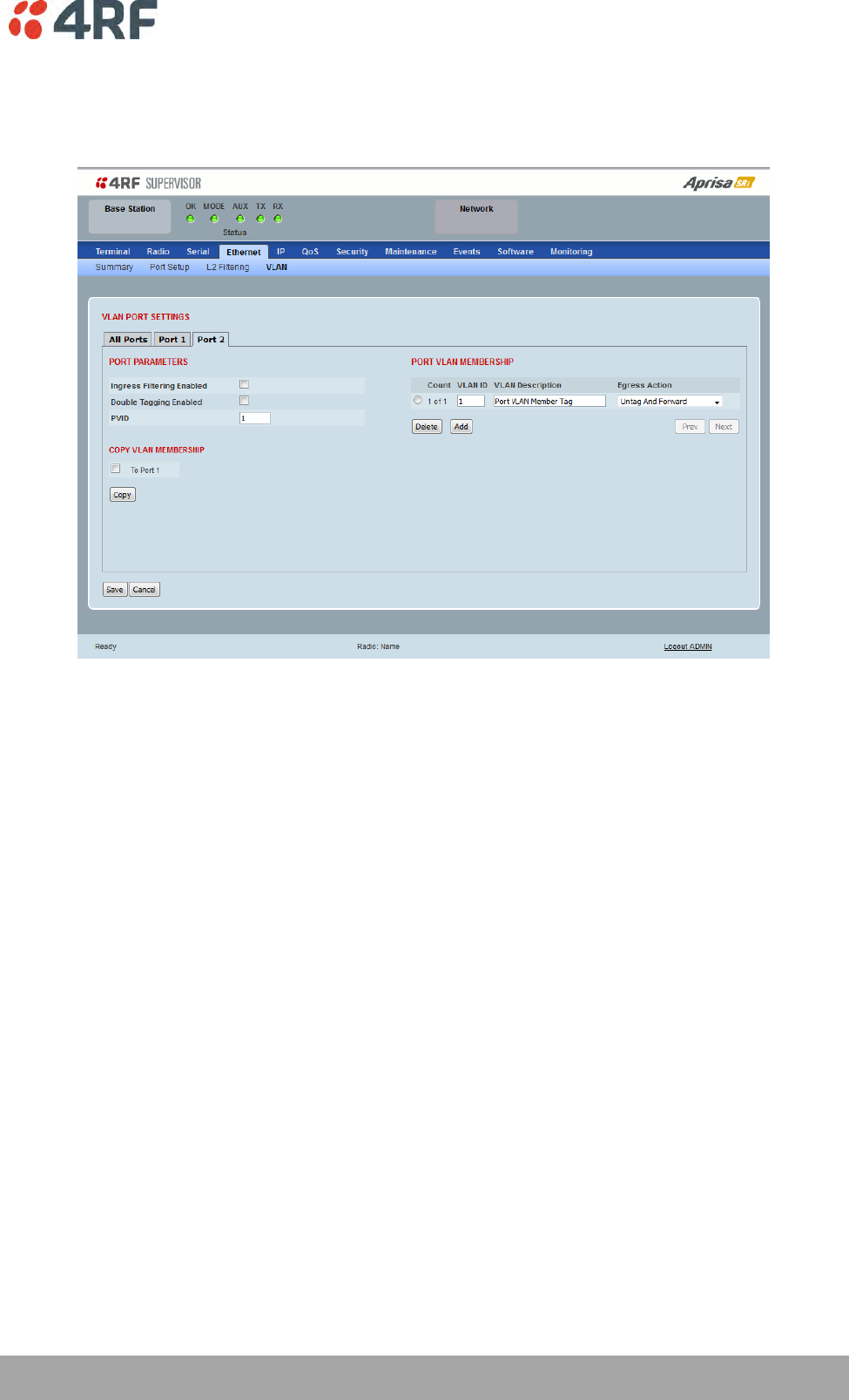
Managing the Radio | 121
Aprisa SRi User Manual 1.0.0
Ethernet > VLAN
This page is only available if the Ethernet traffic option has been licensed (see ‘Maintenance > Licence’ on
page 191).
VLAN PORT SETTINGS – All Ports
This page specifies the parameters that relate to all Ethernet ports when working in Bridge Mode. Three
parameters are global parameters for the Ethernet Bridge; enable / disable VLANs, Management VLAN ID
and the Double VLAN ID(S-VLAN) and the priority bit. These parameters can't be defined per port and are
globally defined for the Ethernet Bridge.
VLAN Enabled
This parameter sets if VLAN operation is required on the network. If it is enabled on the base station, it
must also be enabled on the remote stations. The default is disabled.
Management VLAN
This parameter sets the VLAN ID for management traffic only. The value can be between 1 and 4094. The
default is 1.
Double Tag Egress S-VLAN ID
This parameter sets the S-VLAN ID (outer tag) in the egress direction. The value can be between 1 and
4094. The default is 1.

122 | Managing the Radio
Aprisa SRi User Manual 1.0.0
Double Tag Egress S-VLAN Priority
This parameter sets the S-VLAN egress traffic priority. The default is Priority 1 (Best Effort).
Option
Egress Priority
Classification
High / Low
Priority
Priority 0 Background
0
Lowest Priority
Priority 1 (Best Effort)
1
Priority 2 (Excellent Effort)
2
Priority 3 (Critical Applications)
3
Priority 4 (Video)
4
Priority 5 (Voice)
5
Priority 6 (Internetwork Control)
6
Priority 7 (Network Control)
7
Highest Priority
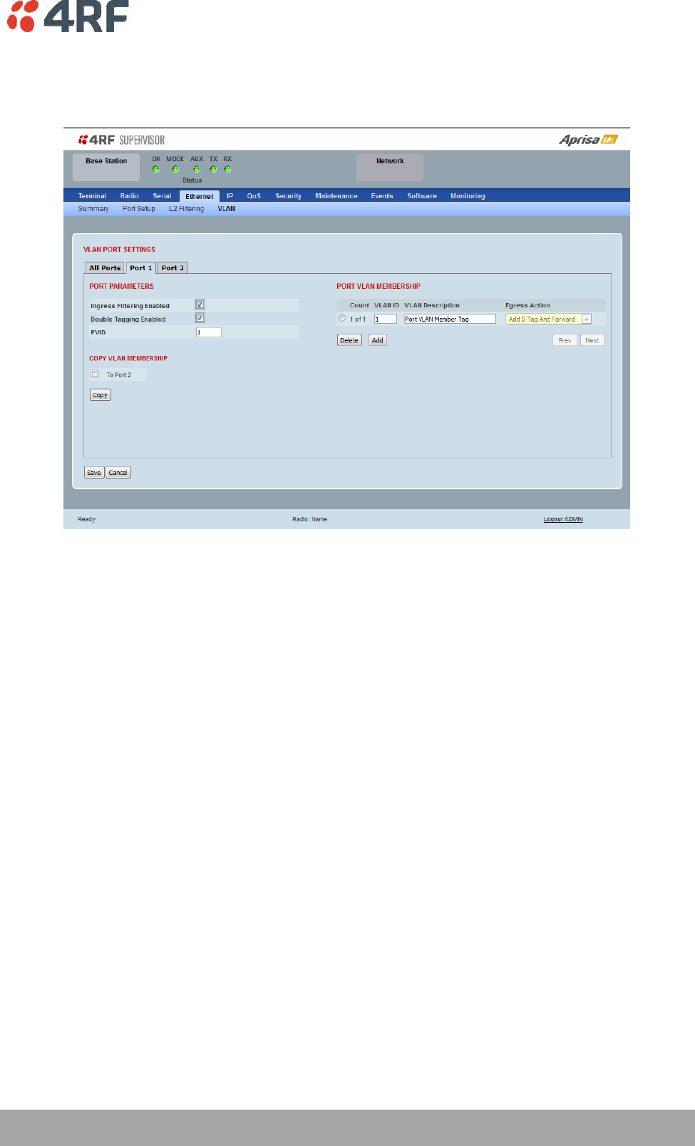
Managing the Radio | 123
Aprisa SRi User Manual 1.0.0
VLAN PORT SETTINGS – Port 1
This example is shown for the product option of 2E2S i.e. two Ethernet ports.
PORT PARAMETERS
Ingress Filtering Enabled
This parameter enables ingress filtering. When enabled, if ingress VLAN ID is not included in its member
set (inner tagged), the frame will be discarded.
If the Ingress Filtering is disabled, the Aprisa SRi supports ‘Admit All Frames’ so that all frames tagged,
untagged and priority-tagged-frames are allowed to pass through the Ethernet ports. The default is
disabled.
Double Tagging Enabled
This parameter enables double tagging on this specific port. When enabled, if the ingress traffic is double
tagged, the Aprisa SRi will check and validate that the S-VLAN ID matches the S-VLAN defined in 'Double
Tag Egress S-VLAN ID' in the 'all ports' tab. If there is a match, the packet will be forwarded into the
Bridge and the S-VLAN outer tag will be removed, thus the radio network will only forward a single VLAN.
If there isn’t a matching S-VLAN, the packet will be discarded. On egress, the outer tag (S-VLAN) is
appended with the 'Double Tag Egress S-VLAN ID' defined in the 'all ports' tab (see page 121). The default
is disabled.

124 | Managing the Radio
Aprisa SRi User Manual 1.0.0
If double tagging is enabled on the port, incoming frames should always be double tagged.
If the incoming frame is untagged, then the PVID (port VLAN ID) is used and forwarded with the Port
Ingress priority provided the PVID is configured in the Port VLAN Membership of any of the Ethernet
ports. If not, the frames are dropped.
If the incoming frame is single tagged, then PVID is used and forwarded with the Port Ingress priority
provided the PVID is configured in the Port VLAN Membership of any of the Ethernet ports. If not the
frames are dropped.
If double tagging is disabled on the port, incoming frames should always be single tagged, untagged or
priority–tagged frames.
Double tagged frames are simply forwarded treating them as if they were single tagged frames. At the
egress of the Ethernet port, such frames are forwarded only if the S-VLAN ID of that frame is a member of
the Port VLAN Membership.
PVID (Port VLAN ID)
This parameter sets the frame VLAN ID when the ingress frame is untagged (e.g. when in 'port VLAN
membership' the 'egress action' is set to 'untagged and forward') or priority-tagged (VLAN=0). The value
can be between 1 and 4094. The default is 1.
Note: The Port VLAN Membership must contain the PVID. If the Port VLAN Membership does not contain
the PVID, untagged or priority-tagged frames will be discarded.
COPY VLAN MEMBERSHIP
To Port
This parameter when set copies the port VLAN Membership settings to the other ports.
PORT VLAN MEMBERSHIP
VLAN ID
This parameter sets the VLAN ID of the port for a maximum 64 active VLANs. The value can be between 1
and 4094. The default is 1.
VLAN Description
This parameter is a freeform field used to identify the VLAN. It can be up to a maximum of 32 characters.

Managing the Radio | 125
Aprisa SRi User Manual 1.0.0
Egress Action
This parameter sets the action taken on the frame on egress from the Ethernet port. The default is Untag
and forward.
Option
Function
Untag and forward
Removes the tagged information and forwards the
frame. On Ingress, the VLAN tag will be added to the
PVID tag.
Forward
Forwards the tagged frame as it is on egress.
On Ingress, traffic is expected to include the VLAN tag
with a member VLAN ID, otherwise the packet will be
dropped.
Controls
The Add button adds the selected entry.
The Delete button deletes the selected entry.
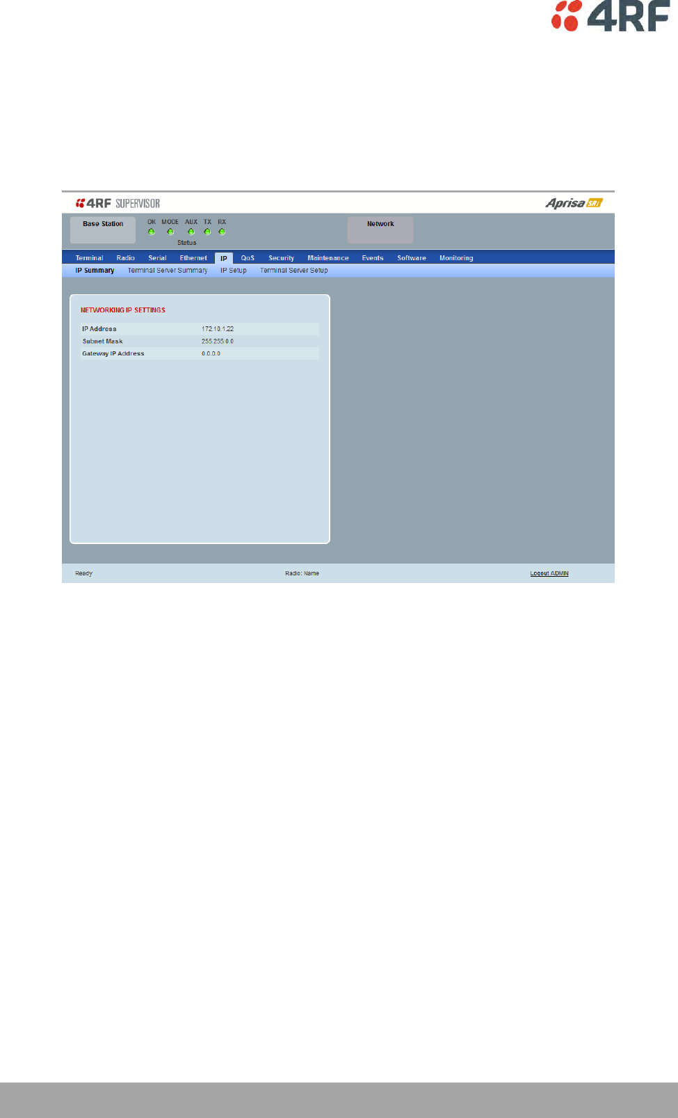
126 | Managing the Radio
Aprisa SRi User Manual 1.0.0
IP
IP > IP Summary > Bridge / Gateway Router Modes
This page displays the current settings for the Networking IP Settings for an Ethernet Operating Mode of
‘Bridge’ or ‘Gateway Router’.
See ‘IP > IP Setup > Bridge / Gateway Router Modes’ on page 129 for configuration options.
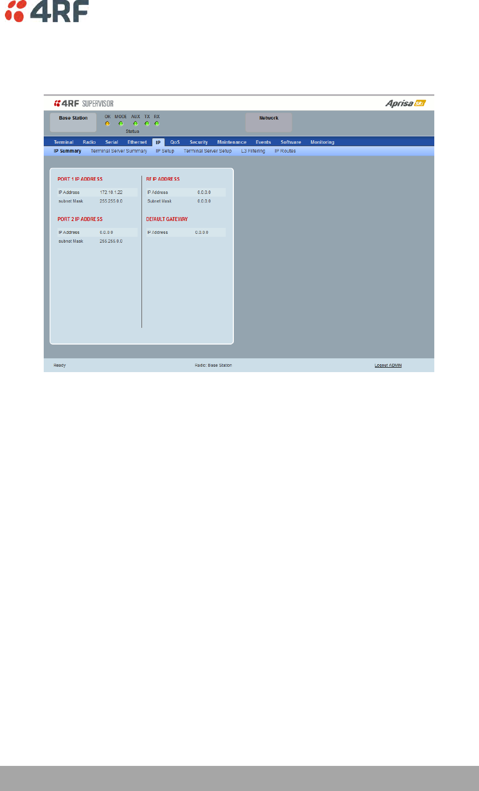
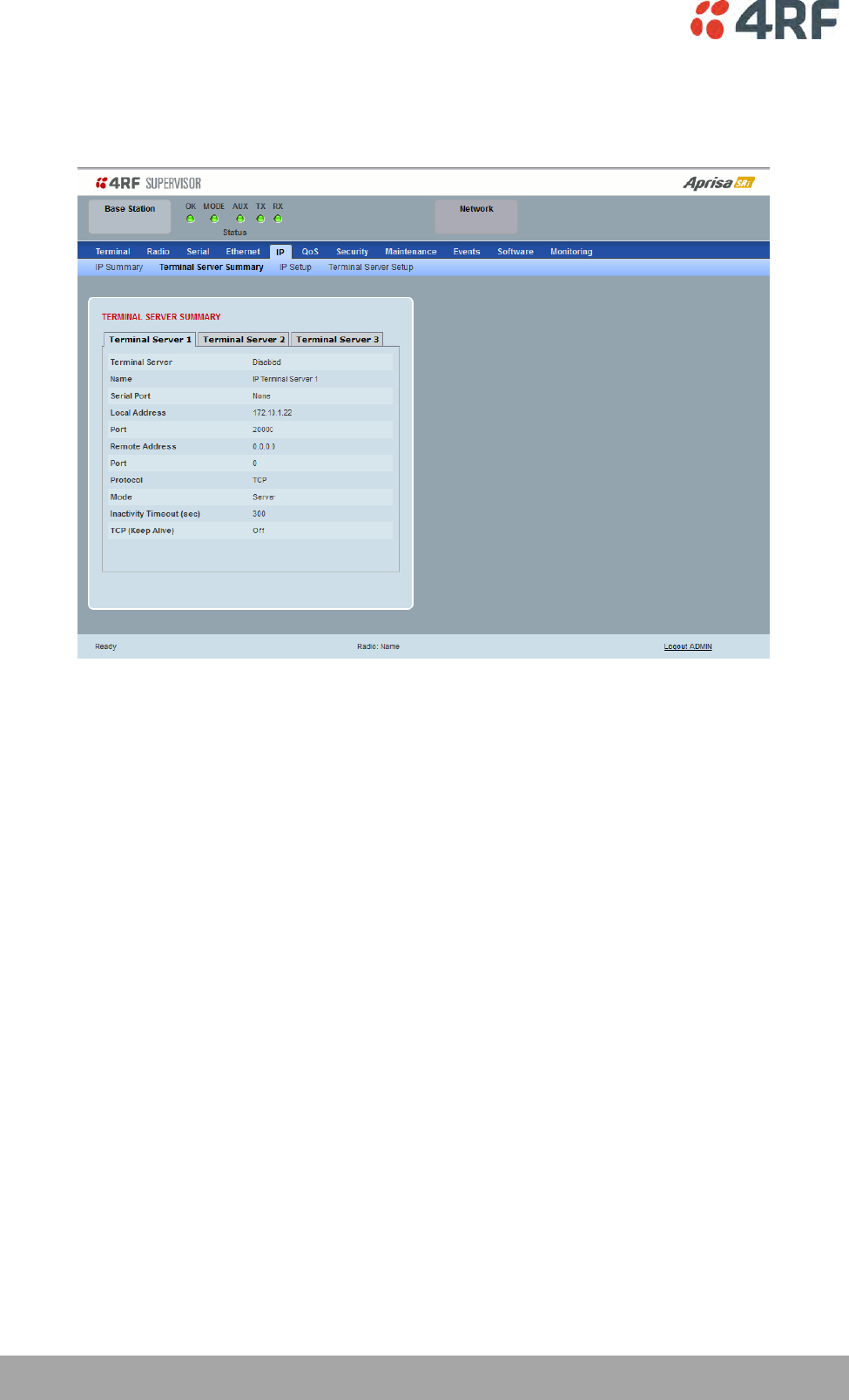
128 | Managing the Radio
Aprisa SRi User Manual 1.0.0
IP > IP Terminal Server Summary
This page provides the setup for the IP Settings for an Ethernet Operating Mode of ‘Bridge’ or ‘Gateway
Router’.
TERMINAL SERVER SUMMARY
IP Terminal Server converts local incoming IP packets to a local physical serial port and to OTA serial
packets.
This function is typically used on a base / master station to convert traffic to serial OTA for transmission
to all remote radios
See ‘IP > IP Terminal Server Setup’ for configuration options.
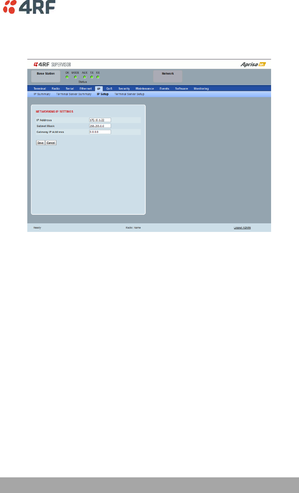
Managing the Radio | 129
Aprisa SRi User Manual 1.0.0
IP > IP Setup > Bridge / Gateway Router Modes
This page provides the setup for the IP Settings for an Ethernet Operating Mode of ‘Bridge’ or ‘Gateway
Router’.
NETWORKING IP SETTINGS
IP Address
Set the static IP Address of the radio (Management and Ethernet ports) assigned by your site network
administrator using the standard format xxx.xxx.xxx.xxx. This IP address is used both in Bridge mode and
in Router mode. The default IP address is in the range 169.254.50.10.
Subnet Mask
Set the Subnet Mask of the radio (Management and Ethernet ports) using the standard format
xxx.xxx.xxx.xxx. The default subnet mask is 255.255.0.0 (/16).
Gateway
Set the Gateway address of the radio, if required, using the standard format xxx.xxx.xxx.
A default gateway is the node on the network that traffic is directed to when an IP address does not
match any other routes in the routing table. It can be the IP address of the router or PC connected to the
base station. The default gateway commonly connects the internal radio network and the outside
network. The default Gateway is 0.0.0.0.
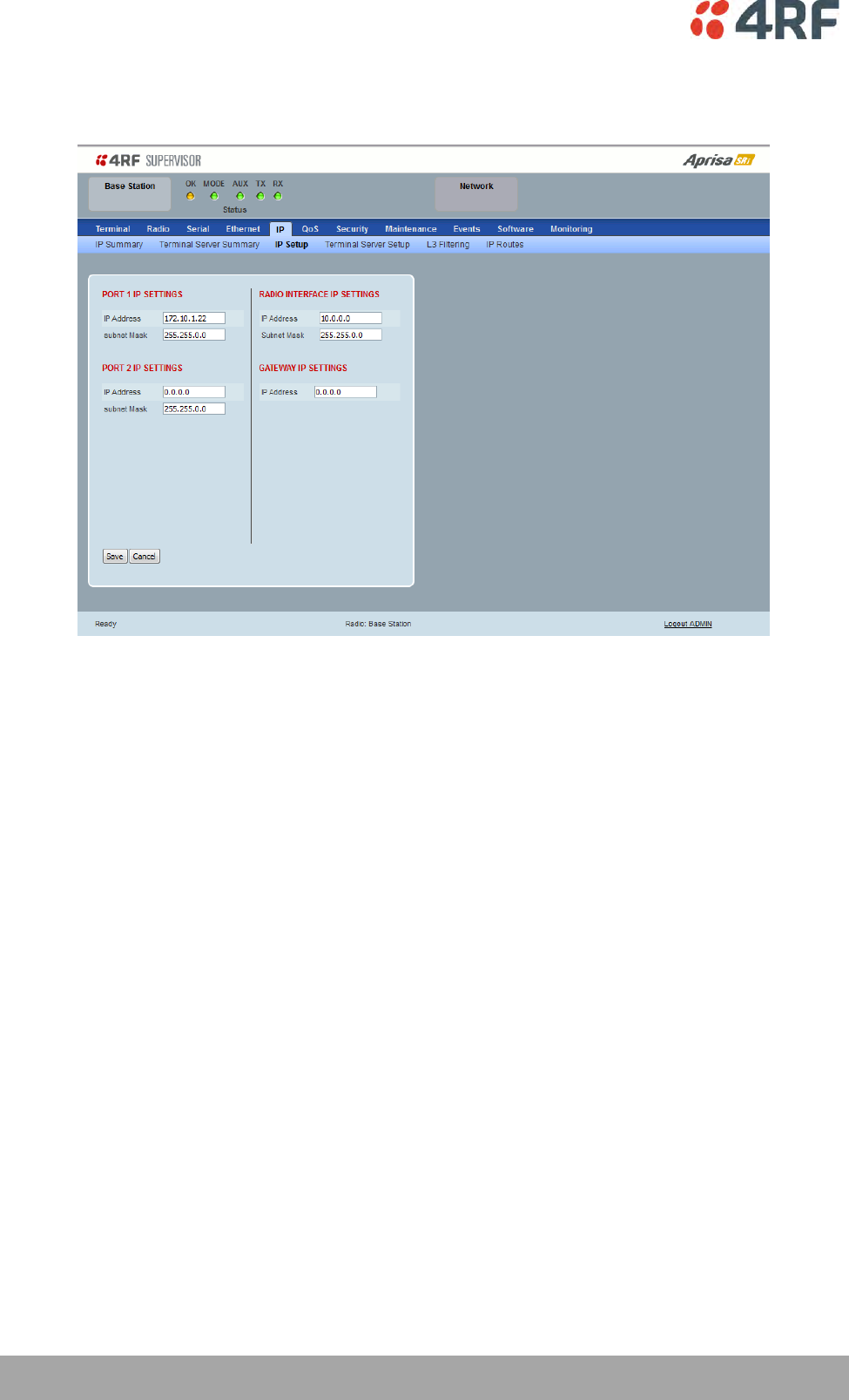
130 | Managing the Radio
Aprisa SRi User Manual 1.0.0
IP > IP Setup > Router Mode
This page provides the setup for the IP Settings for and Ethernet Operating Mode of ‘Router’.
PORT SETTINGS
IP Address
Set the static IP Address of the radio Ethernet port (n) assigned by your site network administrator using
the standard format xxx.xxx.xxx.xxx. This IP address is used for this Ethernet port Router mode.
Subnet Mask
Set the Subnet Mask of the of the radio Ethernet port (n) using the standard format xxx.xxx.xxx.xxx. The
default subnet mask is 255.255.0.0 (/16).
Gateway
Set the Gateway address of the radio Ethernet port (n), if required, using the standard format
xxx.xxx.xxx.
A default gateway is the node on the network that traffic is directed to when an IP address does not
match any other routes in the routing table. It can be the IP address of the router or PC connected to the
base station. The default gateway commonly connects the internal radio network and the outside
network. The default Gateway is 0.0.0.0.

Managing the Radio | 131
Aprisa SRi User Manual 1.0.0
RADIO INTERFACE IP SETTINGS
The RF interface IP address is the address that traffic is routed to for transport over the radio link. This IP
address is only used when Router Mode is selected i.e. not used in Bridge Mode.
Radio Interface IP Address
Set the IP Address of the RF interface using the standard format xxx.xxx.xxx.xxx. The default IP address is
in the range 10.0.0.0.
Radio Interface Subnet Mask
Set the Subnet Mask of the RF interface using the standard format xxx.xxx.xxx.xxx. The default subnet
mask is 255.255.0.0 (/16).
Note 1: If the base station RF interface IP address is a network IP address, and if the remote radio is also
using a network IP address within the same subnet or different subnet, then the base radio will assign an
automatic RF interface IP address from its own subnet.
When the base radio has a host specific RF interface IP address, then all the remotes must have a host
specific RF interface IP address from the same subnet.
Note 2: When a remote radio is configured for Router Mode and the base radio is changed from Bridge
Mode to Router Mode and the RF interface IP address is set to AUTO IP configuration (at least the last
octet of the RF interface IP address is zero), it is mandatory to configure the network topology by using
the ‘Decommission Node’ and ‘Discover Nodes’ (see ‘Maintenance > Advanced’ on page 192).
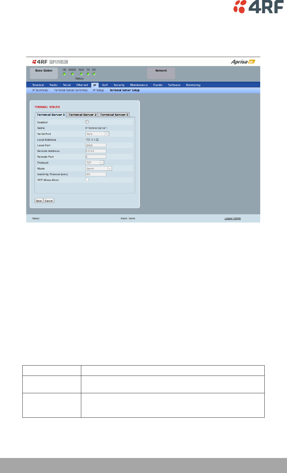
132 | Managing the Radio
Aprisa SRi User Manual 1.0.0
IP > IP Terminal Server Setup
This page provides the setup for the IP Settings for an Ethernet Operating Mode of ‘Bridge’ or ‘Gateway
Router’.
TERMINAL SERVER
Enabled
This parameter enables IP terminal server.
IP Terminal Server converts local incoming IP packets to a local physical serial port and to OTA serial
packets as well. This function is typically used on a base / master station to convert traffic to serial OTA
for transmission to all remote radios.
Name
This parameter displays the IP terminal server port name.
Serial Port
This parameter selects the serial port to use IP terminal server.
Option
Function
Serial Port
This is the normal RS-232 serial ports provided with the RJ45
connector.
USB Serial Port
This is the optional RS-232 / RS-485 serial port provided with the
USB host port connector with a USB to RS-232 / RS-485 RJ45
converter cable (see ‘USB Serial Ports’ on page 261).

Managing the Radio | 133
Aprisa SRi User Manual 1.0.0
Local Address
This parameter displays the IP address of this radio.
Local Port
This parameter sets the TCP or UDP port number of the local serial port.
The valid port number range is greater than or equal to 1024 and less than or equal to 49151 but with
exclusions of 0, 5445, 6445, 9930 or 9931. The default setting is 20000.
Remote Address
This parameter sets the IP address of the server connected to the radio Ethernet port.
Remote Port
This parameter sets the TCP or UDP port number of the server connected to the radio Ethernet port. The
default setting is 0.
Protocol
This parameter sets the L4 TCP/IP or UDP/IP protocol used for terminal server operation. The default
setting is TCP.
Mode
This parameter defines the mode of operation of the terminal server connection. The default setting is
Client and Server.
Option
Function
Client
The radio will attempt to establish a TCP connection with the
specified remote unit. Generally, this setting is for the base station
with an Ethernet connection to the SCADA master.
Server
The radio will listen for a TCP connection on the specified local
port. Generally, this setting is for the remote station with a serial
connection to the RTU.
Data received from any client shall be forwarded to the associated
serial port while data received from that serial port shall be
forwarded to every client with an open TCP connection.
If no existing TCP connections exist, all data received from the
associated serial port shall be discarded.
Client and Server
The radio will listen for a TCP connection on the specified local
port and if necessary, establish a TCP connection with the
specified remote unit. Generally, this setting is used for the
remote station but it should be used carefully as two connections
might be established with the base station.
Data received from any client shall be forwarded to the associated
serial port while data received from that serial port shall be
forwarded to every client with an open TCP connection.

134 | Managing the Radio
Aprisa SRi User Manual 1.0.0
Inactivity Timeout (seconds)
This specifies the duration (in seconds) to automatically terminate the connection with the remote TCP
server if no data has been received from either the remote TCP server or its associated serial port for the
duration of the configured inactivity time.
TCP Keep Alive
A TCP keep alive is a message sent by one device to another to check that the link between the two is
operating, or to prevent the link from being broken.
If the TCP keep alive is enabled, the radio will be notified if the TCP connection fails.
If the TCP keep alive is disabled, the radio relies on the Inactivity Timeout to detect a TCP connection
failure. The default setting is disabled.
Note: An active TCP keep alive will generate a small amount of extra network traffic.
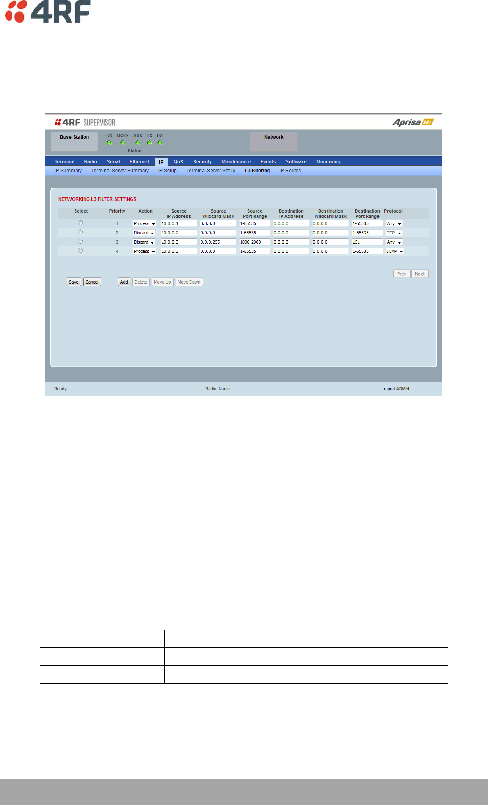
Managing the Radio | 135
Aprisa SRi User Manual 1.0.0
IP > L3 Filtering
This page is only available if the Ethernet traffic option has been licensed (see ‘Maintenance > Licence’ on
page 191) and Router Mode selected. The filter operates in either Bridge Mode or Router Mode (see
'Terminal > Operating Mode’ on page 86).
NETWORKING L3 FILTER SETTINGS
L3 Filtering provides the ability to evaluate traffic and take specific action based on the filter criteria.
This filtering can also be used for L4 TCP / UDP port filtering which in most cases relates to specific
applications as per IANA official and unofficial well-known ports.
Entering a * into any to field will automatically enter the wildcard values when the data is saved.
Priority
This parameter shows the priority order in which the filters are processed.
Action
This parameter defines the action taken on the packet when it meets the filter criteria.
Option
Function
Process
Processes the packet if it meets the filter criteria
Discard
Discards the packet if it meets the filter criteria
Source IP Address
If the source IP address is set to 0.0.0.0, any source IP address will meet the filter criteria.

136 | Managing the Radio
Aprisa SRi User Manual 1.0.0
Source Wildcard Mask
This parameter defines the mask applied to the source IP address. 0 means that it must be a match.
If the source wildcard mask is set to 0.0.0.0, the complete source IP address will be evaluated for the
filter criteria.
If the source wildcard mask is set to 0.0.255.255, the first 2 octets of the source IP address will be
evaluated for the filter criteria.
If the source wildcard mask is set to 255.255.255.255, none of the source IP address will be evaluated for
the filter criteria.
Note: The source wildcard mask operation is the inverse of subnet mask operation
Source Port Range
This parameter defines the port or port range for the source. To specify a range, insert a dash between
the ports e.g. 1000-2000. If the source port range is set to 1-65535, traffic from any source port will meet
the filter criteria.
Destination IP Address
This parameter defines the destination IP address of the filter. If the destination IP address is set to
0.0.0.0, any destination IP address will meet the filter criteria.
Destination Wildcard Mask
This parameter defines the mask applied to the destination IP address. 0 means that it must be a match.
If the destination wildcard mask is set to 0.0.0.0, the complete destination IP address will be evaluated
for the filter criteria.
If the destination wildcard mask is set to 0.0.255.255, the first 2 octets of the destination IP address will
be evaluated for the filter criteria.
If the destination wildcard mask is set to 255.255.255.255, none of the destination IP address will be
evaluated for the filter criteria.
Note: The destination wildcard mask operation is the inverse of subnet mask operation
Destination Port Range
This parameter defines the port or port range for the destination. To specify a range, insert a dash
between the ports e.g. 1000-2000. If the destination port range is set to 1-65535, traffic to any
destination port will meet the filter criteria.
Protocol
This parameter defines the Ethernet packet type that will meet the filter criteria.
Controls
The Delete button deletes the selected entry.
The Move Up button moves the selected entry above the entry above it increasing its process priority.
The Move Down button moves the selected entry below the entry above it reducing its process priority.
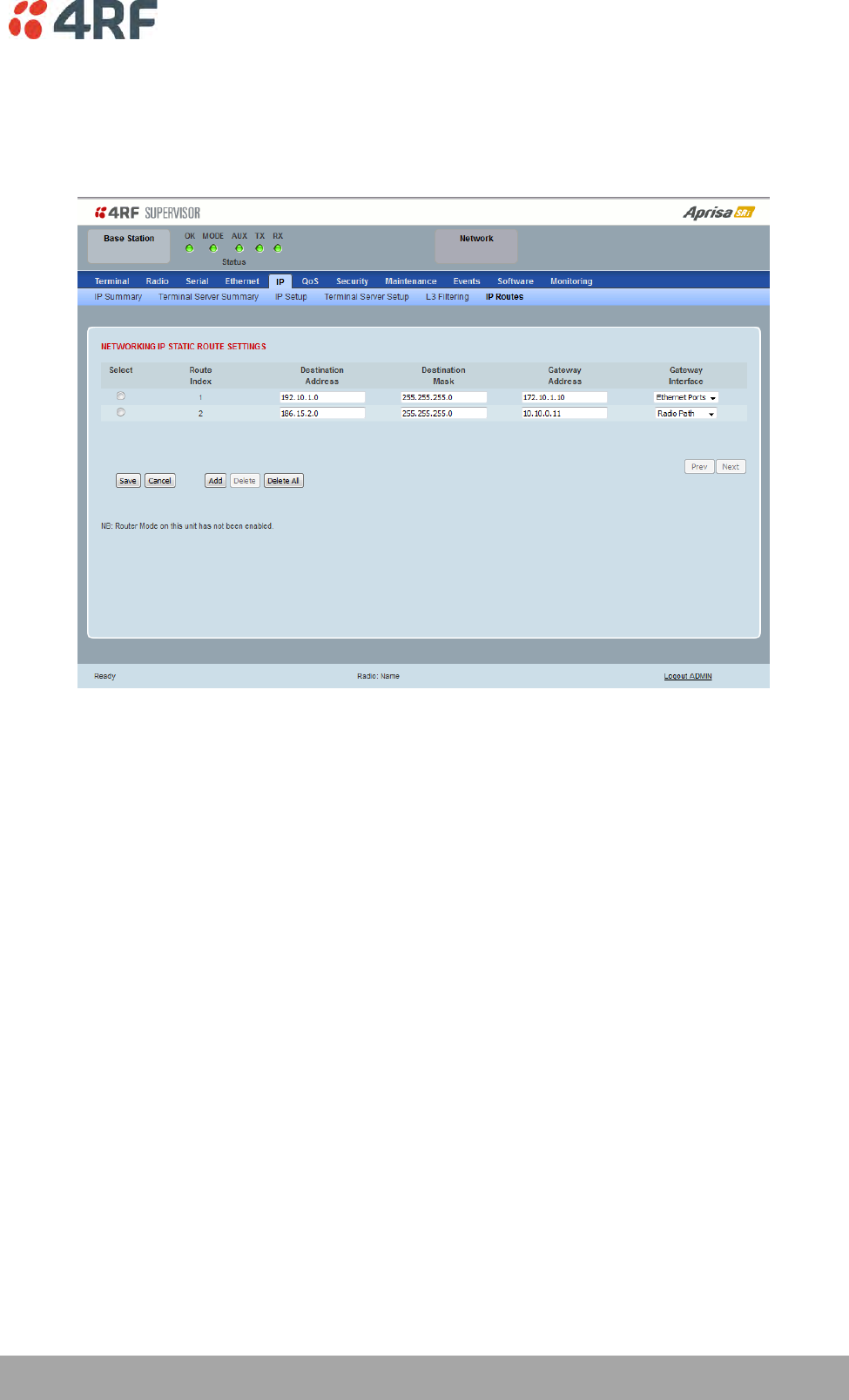
Managing the Radio | 137
Aprisa SRi User Manual 1.0.0
IP > IP Routes
This page is only available if the Ethernet traffic option has been licensed (see ‘Maintenance > Licence’ on
page 191) and Router Mode selected. It is not valid for Bridge Mode (see 'Terminal > Operating Mode’ on
page 86).
NETWORKING IP STATIC ROUTE SETTINGS
Static routing provides the ability to evaluate traffic to determine if packets are forwarded over the radio
link or discarded based on the route criteria.
Route Index
This parameter shows the route index.
Destination Address
This parameter defines the destination IP address of the route criteria.
Destination Mask
This parameter defines the subnet mask applied to the Destination IP Address. 255 means that it must be a
match.
If the destination subnet mask is set to 255.255.255.255, all octets of the Destination IP Address will be
evaluated for the route criteria.
If the destination subnet mask is set to 255.255. 0.0, the first 2 octets of the Destination IP Address will be
evaluated for the route criteria.

138 | Managing the Radio
Aprisa SRi User Manual 1.0.0
Gateway Address
This parameter sets the gateway address where packets will be forwarded to.
If the gateway interface is set to Ethernet Ports, the gateway address is the IP address of the
device connected to the Ethernet port.
If the gateway interface is set to Radio Path, the gateway address is the IP address of the remote
radio.
Gateway Interface
This parameter sets the destination interface.
Option
Function
Ethernet Ports
Packets are forwarded to the Ethernet interface port.
Radio Path
Packets are forwarded to the RF Interface radio path.
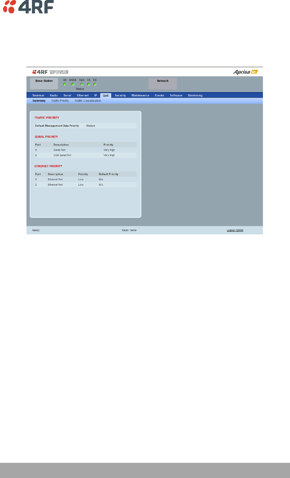

140 | Managing the Radio
Aprisa SRi User Manual 1.0.0
QoS > Traffic Priority
TRAFFIC PRIORITY
Default Management Data Priority
The Default Management Data Priority controls the priority of the Ethernet management traffic relative to
Ethernet customer traffic. It can be set to Very High, High, Medium and Low. The default setting is
Medium.
This priority is also used for traffic if the remote serial port is not available for the radio hardware data
port option e.g. if the base station is 2E2S and a remote radio is 4E0S.
SERIAL PRIORITY
This parameter controls the per port priority of the serial customer traffic relative to the Ethernet
customer traffic. If equal priority is required to Ethernet traffic, this setting must be the same as the
Ethernet Data Priority setting.
The serial data priority can be set to Very High, High, Medium and Low. The default setting is Low.
A queuing system is used to prioritize traffic from the serial and Ethernet interfaces for over the air
transmission. A weighting may be given to each data type and this is used to schedule the next
transmission over the air e.g. if there are pending data packets in multiple buffers but serial data has a
higher weighting it will be transmitted first. The serial buffer is 20 serial packets (1 packet can be up to
512 bytes).
There are four priority queues in the Aprisa SR: Very High, High, Medium and Low. Data is added to one of
these queues depending on the priority setting. Data leaves the queues from highest priority to lowest:
the Very High queue is emptied first, followed by High then Medium and finally Low.

Managing the Radio | 141
Aprisa SRi User Manual 1.0.0
ETHERNET PRIORITY
This parameter controls the per port priority of the Ethernet customer traffic relative to the serial
customer traffic. If equal priority is required to serial traffic, this setting must be the same as the Serial
Data Priority setting.
The Ethernet Priority enables users to set the priority of Ethernet port ingress frames. The priority for
each port can be:
1. From PCP priority bits (VLAN priority) in VLAN tagged frames or priority tag (VLAN 0) frames
2. From DSCP priority bits in an IP packet (DSCP in IPv4 TOS field)
3. All frames are set to ‘very high’ priority
4. All frames are set to ‘high’ priority
5. All frames are set to ‘medium’ priority
6. All frames are set to ‘low’ priority
The default setting is Low.
A queuing system is used to prioritize customer traffic from the serial and Ethernet interfaces for over the
air transmission. A weighting may be given to each data type and this is used to schedule the next
transmission over the air e.g. if there are pending data packets in multiple buffers but serial data has a
higher weighting it will be transmitted first. The Ethernet buffer is 10 Ethernet packets (1 packet can be
up to Ethernet MTU, 1536 bytes).
There are four priority queues in the Aprisa SRi: Very High, High, Medium and Low. Data is added to one of
these queues depending on the priority setting. Data leaves the queues from highest priority to lowest:
the Very High queue is emptied first, followed by High then Medium and finally Low.
Default Priority
When the priority of an Ethernet port uses the PCP bits (VLAN priority) values the ‘Default Priority’ option
is enabled, allowing the priority of untagged VLAN frames to be set.
When the priority of an Ethernet port uses the DSCP priority (in IPv4 TOS field) values the ‘Default
Priority’ option is enabled, allowing the priority of ARP frames to be set.
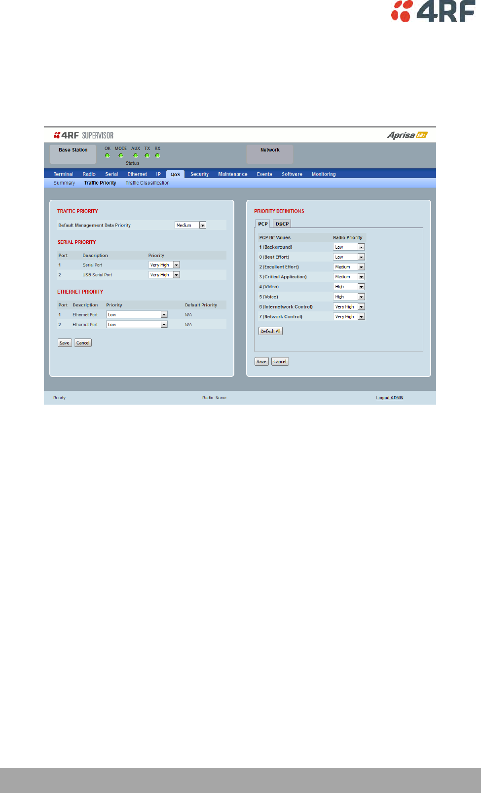
142 | Managing the Radio
Aprisa SRi User Manual 1.0.0
PRIORITY DEFINITIONS
PCP (Priority Code Point)
These settings provide priority translation / mapping between the external radio LAN VLAN priority
network and the radio internal VLAN priority network, using the VLAN tagged PCP (Priority Code Point)
priority field in the Ethernet/VLAN frame.
The IEEE 802.1Q specification defines a standards-based mechanism for providing VLAN tagging and class
of service (CoS) across Ethernet networks. This is accomplished through an additional VLAN tag, which
carries VLAN tag ID and frame prioritization information (PCP field), inserted within the header of a Layer
2 Ethernet frame.
Priority Code Point (PCP) is a 3-bit field that indicates the frame priority level (or CoS). The operation of
the PCP field is defined within the IEEE 802.1p standard, which is an extension of 802.1Q. The standard
establishes eight levels of priority, referred to as CoS values, where CoS 7 (‘111’ in PCP filed) is the
highest priority and CoS 0 (‘000’) is the lowest priority.
The radio in bridge mode used the PCP value in the VLAN tag to prioritize packets and provide the
appropriate QoS treatment per traffic type. The radio implements 4 priority queuing techniques that base
its QoS on the VLAN priority (PCP). Based on VLAN priority bits, traffic can be put into a particular Class of
Service (CoS) queue. Packets with higher CoS will always serve first for OTA transfer and on ingress/egress
Ethernet ports.
The ‘PCP priority definition’ tab is used to map ingress VLAN packet with PCP priority to the radio internal
CoS (priority). Since, in most of the cases the radio VLAN network is connected to the corporate VLAN
networks, the network administrator might like to have a different VLAN priority scheme of the radio
network CoS. For example, management traffic in the multi-gigabit corporate VLAN network might be
prioritize with priority 7 (highest priority) and SCADA traffic with priority 5, but in the narrow bandwidth
radio network, SCADA traffic will be map to radio very high CoS / priority (i.e. set PCP 5 = Very high) and
management traffic might will be map to radio medium CoS / priority (i.e. set PCP 7 = medium) in order
to serve first the mission-critical SCADA traffic over the radio network.

Managing the Radio | 143
Aprisa SRi User Manual 1.0.0
This is done by mapping the external radio network VLAN priority to the internal radio CoS / priority using
the ‘PCP priority definition’ tab. The radio support 4 queues, thus at maximum an 8 -> 4 VLAN priority /
CoS mapping is done.
Default mapping of ingress packet VLAN priority to radio CoS / priority shown in the ‘PCP priority
definition’ tab.
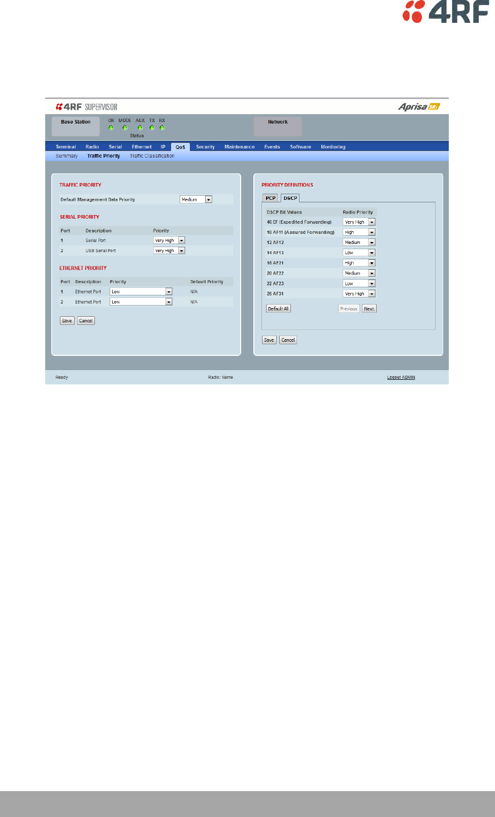
144 | Managing the Radio
Aprisa SRi User Manual 1.0.0
DSCP (Differentiated Services Code Point)
These settings provide translation / mapping between the external radio IP priority network and the radio
internal IP priority network, using the DSCP (DiffServ Code Point) priority field in the IP packet header.
Differentiated Services (DiffServ) is a new model in which traffic is treated by routers with relative
priorities based on the IPv4 type of services (ToS) field. DSCP (DiffServ Code Point) standard defined in
RFC 2474 and RFC 2475. DiffServ increases the number of definable priority levels by reallocating bits of
an IP packet for priority marking.
The DiffServ architecture defines the DiffServ (DS) field, which supersedes the ToS field in IPv4 to make
per-hop behaviour (PHB) decisions about packet classification and traffic scheduling functions. The six
most significant bits of the DiffServ field (in the IPv4 TOS field) is called as the DSCP. The standardized
DiffServ field of the packet is marked with a value so that the packet receives a particular
routing/forwarding treatment or PHB, at each router node. Using DSCP packet classification, traffic can be
partition into multiple priority levels.
The radio in router mode uses the DSCP value in the IP header to select a PHB behaviour for the packet
and provide the appropriate QoS treatment. The radio implements 4 priority queuing techniques that base
its PHB on the DSCP in the IP header of a packet. Based on DSCP, traffic can be put into a particular
priority / CoS (Class of Service) queue. Packets with higher CoS will always serve first for OTA transfer and
on ingress / egress Ethernet ports.
The ‘DSCP priority definition’ tab is used to map ingress IP packet with DSCP priority to the radio internal
priority / CoS. Since, in most of the cases the radio routed network is connected to the corporate routed
networks, the network administrator might like to have a different routed network priority scheme of the
radio network, for example management traffic in the multi-gigabit corporate routed network might be
prioritize with DSCP EF (expedite forwarding) code (DSCP highest priority), and SCADA traffic with DSCP
AF11 (assured forwarding) code (high priority), but in the narrow bandwidth radio network, SCADA traffic
will be map to radio very high CoS / priority (i.e. set AF11 = Very high) and management traffic might map
to radio low CoS / priority (i.e. set EF = Low) in order to serve first the mission-critical SCADA traffic over
the radio network.

Managing the Radio | 145
Aprisa SRi User Manual 1.0.0
This is done by mapping the external radio network DSCP priority to the internal radio CoS / priority levels
using the ‘DSCP priority definition’ tab. The radio support four queues, thus at maximum a 64 -> 4 CoS /
priority mapping is done.
Default mapping of ingress packet DSCP priority to radio CoS shown in the ‘DSCP priority definition’ tab.
The radio maps all 64 DSCP values. The user can configure most common used 21 DSCP codes and the rest
are mapped by default to low CoS / priority.

146 | Managing the Radio
Aprisa SRi User Manual 1.0.0
QoS > Traffic Classification
These settings provide multiple traffic classification profiles based on classification rules. Profiles for a
specific traffic type, protocol or application can be assigned to a particular VLAN and CoS / priority in
bridge mode or to CoS / priority in router mode to provide the appropriate QoS treatment.
For example SCADA traffic, management traffic, FTP traffic, can each have its own profile build with a set
of classification rules. A profile can be build using multiple classification rules based on ports, Ethernet,
IP, TCP / UDP headers fields (i.e. L1/2/3/4 header fields) such as: Ethernet port #1, VLAN ID, VLAN
priority, IP DSCP Priority, MAC/IP address, TCP / UDP port fields to identify and classify the specific traffic
type. When an ingress packet matches the profile L2/3/4 header fields settings, the packet is assigned to
a particular VLAN and CoS / priority in bridge mode or to CoS / priority in router mode to provide the
appropriate QoS treatment.
The radio supports four CoS / priority queues: very high, high, medium and low. These queues are
connected to a strict priority scheduler which dispatches packets from the queues out to the egress port
by always serving first the ‘very high’ priority queue, whenever there is a packet in this queue. When the
highest priority queue empties, the scheduler will serve the next high priority queues and so on. So when
SCADA traffic is assigned to a ‘Very high’ priority, it will always served first and send over-the-air (OTA)
whenever SCADA traffic enters to the radio, giving it the highest priority over other traffic type.
These settings are different for Bridge Mode and Router Mode.

Managing the Radio | 147
Aprisa SRi User Manual 1.0.0
Bridge Mode Traffic Classification Settings
TRAFFIC CLASSIFICATION
VLAN bridge mode traffic classification settings provide mapping / assigning of profiles (set by rules to
match a specific traffic type) to a VLAN ID and VLAN CoS / priority. The profile which is used to match to
a specific traffic type will be identified in the radio network by its associated VLAN ID and VLAN CoS /
priority to provide the appropriate QoS treatment. CoS / Priority can be set to very high, high, medium,
low priority.
Profile name
A free form field to enter the profile name with a maximum of 32 chars.
Assigned Priority
Traffic packets that match the applied profile rules will be assigned to the selected ‘assigned priority’
setting of Very High, High, Medium and Low. This field cannot be set to Don’t Care.
This applies profile rule mapping to the VLAN CoS / Priority with the appropriate internal radio assigned
priority setting of Very High, High, Medium and Low.

148 | Managing the Radio
Aprisa SRi User Manual 1.0.0
Assigned VLAN ID
Traffic packets that match the applied profile rules will be assigned to the selected ‘assigned VLAN ID’
setting of VLAN ID in the range of 0 to 4095.
A VLAN ID of an ingress packet matching the classification rule (see ‘VLAN ID’ rule in next page) shall be
changed to the ‘assigned VLAN ID’ setting, if below conditions are met:
1. The VLAN ID of Ingress packet is same as PVID of the ingress port.
2. Packet is received untagged at the port
If the VLAN ID of the tagged ingress packet is not the same as the PVID of the ingress port, then it shall
not be changed and the ‘assigned VLAN ID’ setting is ignored i.e. ingress VLANs will pass-through
unchanged.
If ‘assigned VLAN ID’ value is set in the ‘port VLAN membership’ under Ethernet > VLAN (port x tab), then
this VLAN will be available for ingress and egress on the Ethernet and RF ports, otherwise this VLAN will
only be available in one direction on the egress RF port.
For example, if the base station Ethernet port 1 ‘assigned VLAN ID’ = 100 (VLAN-100) and it is also defined
in the ‘port VLAN membership’ under Ethernet > VLAN (port 1 tab) and the remote sends a packet to the
base with a VLAN of 100, this packet will be egress out to Ethernet port 1 (tagged or untagged based on
the ‘egress action’ definition). If the VLAN-100 wasn’t set in the ‘port VLAN membership’, then the base
station will drop a packet from the remote.
This setting parameter can be ‘Don’t Care’ (Assigned VLAN ID = 0) which means that the VLAN ID of ingress
frame will never be modified.
Active
Activates or deactivates the profile rule.
Controls
The Save button saves all profiles to the radio.
The Cancel button removes all changes since the last save or first view of the page if there has not been
any saves. This button will un-select all the Select radio buttons.
The Edit button will show the next screen for the selected profile where the profile can be configured.
This button will be disabled unless a profile is selected.
The Add button adds a new profile,
If no profile was selected then the new profile is added to the end of the list,
If a profile is selected the new profile is added after that profile.
The Delete button will delete the selected profile. The button will be disabled unless a profile has been
selected.
The Delete All button will delete all the profiles. A pop-up will ask if the action is correct. If the answer is
yes, then all profiles are deleted in SuperVisor. The Save button must be pressed to delete all the profiles
in the radio.
The Move up button will move the selected profile up one in the order of profiles
The Move Down button will move the selected profile down one in the order of profiles
The Previous button displays the previous page in the list of profiles. A pop up will be displayed if any
profile has been modified and not saved, preventing the previous page being displayed.
The Next button will display the next page in the list of profiles.

Managing the Radio | 149
Aprisa SRi User Manual 1.0.0
To edit a traffic classification, select the profile and click on the Edit button
ETHERNET PORT CRITERIA
Ethernet Port
Set the layer 1 Ethernet port number or all Ethernet ports in the selected profile classification rule.
VLAN ID
Sets the layer 2 packet Ethernet header VLAD ID field in the selected profile classification rule. Valid
values are between 0 and 4095. This VLAN ID should be enabled in the system for using this parameter
during classification.
Enable this VLAN in the network by setting the same VLAN ID value in PVID (port VLAN ID) and in the PORT
VLAN MEMBERSHIP under ‘VLAN PORT SETTINGS – Port 1’ on page 123. If the VLAN ID is set to zero, all
VLAN IDs will meet the criteria.
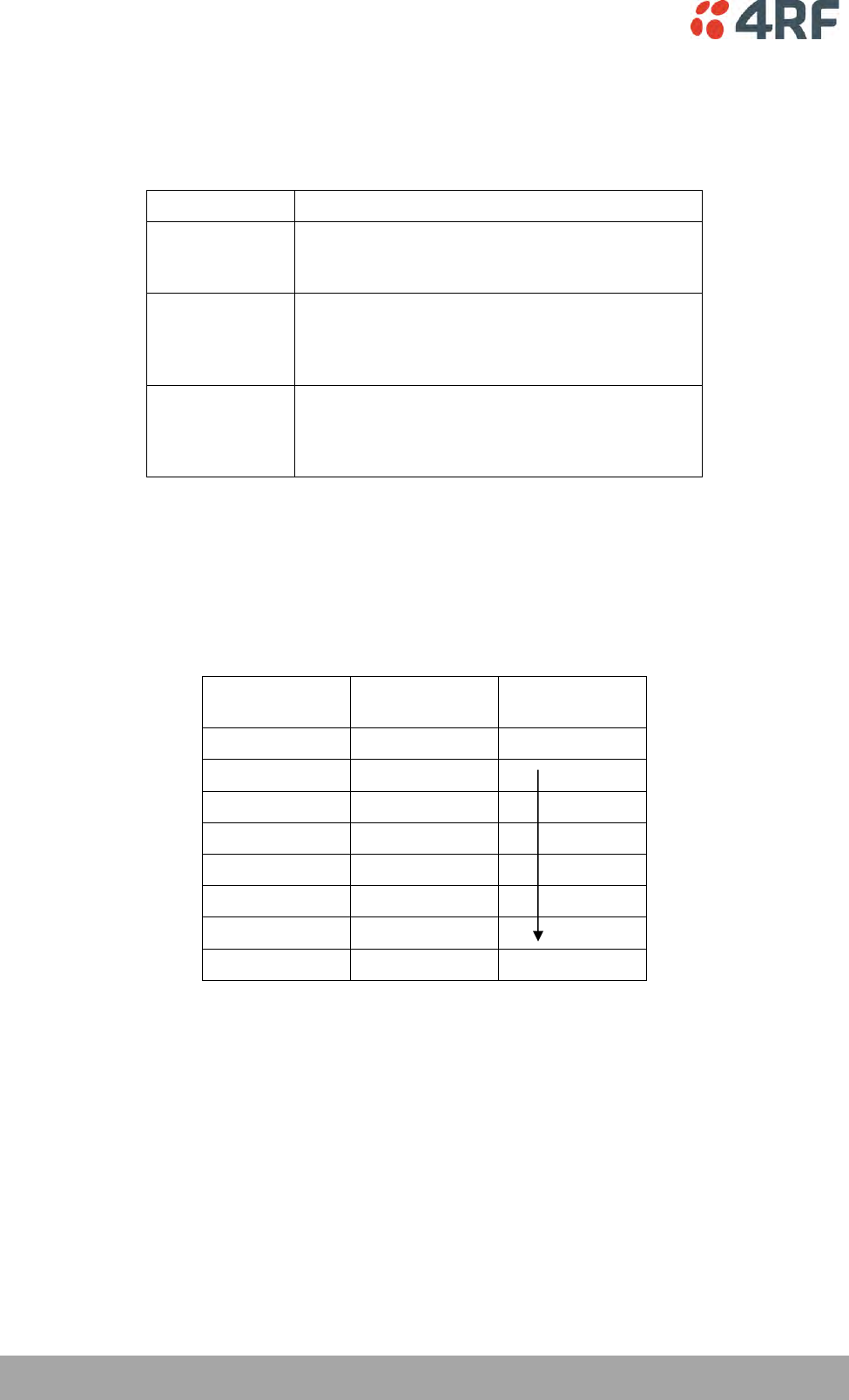
150 | Managing the Radio
Aprisa SRi User Manual 1.0.0
PRIORITY CRITERIA
Priority Type
Set the layer 2 Ethernet or layer 3 IP packet header priority type fields in the selected profile
classification rules.
Priority Type
Description
None
Do not use any layer 2 / 3 Ethernet or IP header
priority fields in the selected profile classification
rules.
PCP
Use the layer 2 Ethernet header priority field of
PCP (Priority Code Point) VLAN priority bits (per
IEEE 802.1p/q) in the selected profile
classification rules.
DSCP
Use the layer 3 IP header TOS field used as DSCP
(Differentiated Services Code Point per RFC 2474
and RFC 2475) priority bit in the selected profile
classification rules.
PCP / DSCP Range
As per the ‘priority type’ selection, this parameter sets the PCP priority value/s or DSCP priority value/s
fields in the selected profile classification rule. The value can be set to a single priority or a single range
(no multiple ranges are allowed), for example, the PCP selected priority value can be 7 or a range of
priority values like 4-7.
The following table shows the layer 2 packet VLAN tag header PCP priority field values
PCP Value
(Decimal)
PCP Priority
Priority Level
7
Priority [7]
Highest
6
Priority [6]
5
Priority [5]
4
Priority [4]
3
Priority [3]
2
Priority [2]
1
Priority [1]
0
Priority [0]
Lowest
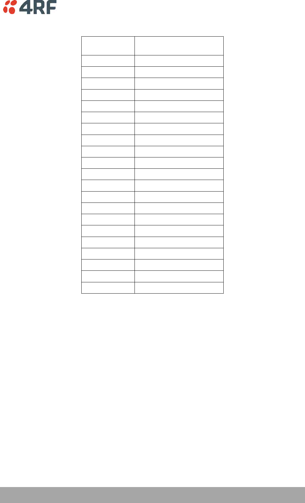
Managing the Radio | 151
Aprisa SRi User Manual 1.0.0
The following table shows the layer 3 packet IP header DSCP priority field values
DSCP Value
(Decimal)
DSCP Priority
46
EF (Expedited Forwarding)
10
AF11 (Assured Forwarding)
12
AF12
14
AF13
18
AF21
20
AF22
22
AF23
26
AF31
28
AF32
30
AF33
34
AF41
36
AF42
38
AF43
0
CS0/Best Effort (BE)
8
CS1 (Class Selector )
16
CS2
24
CS3
32
CS4
40
CS5
48
CS6
56
CS7
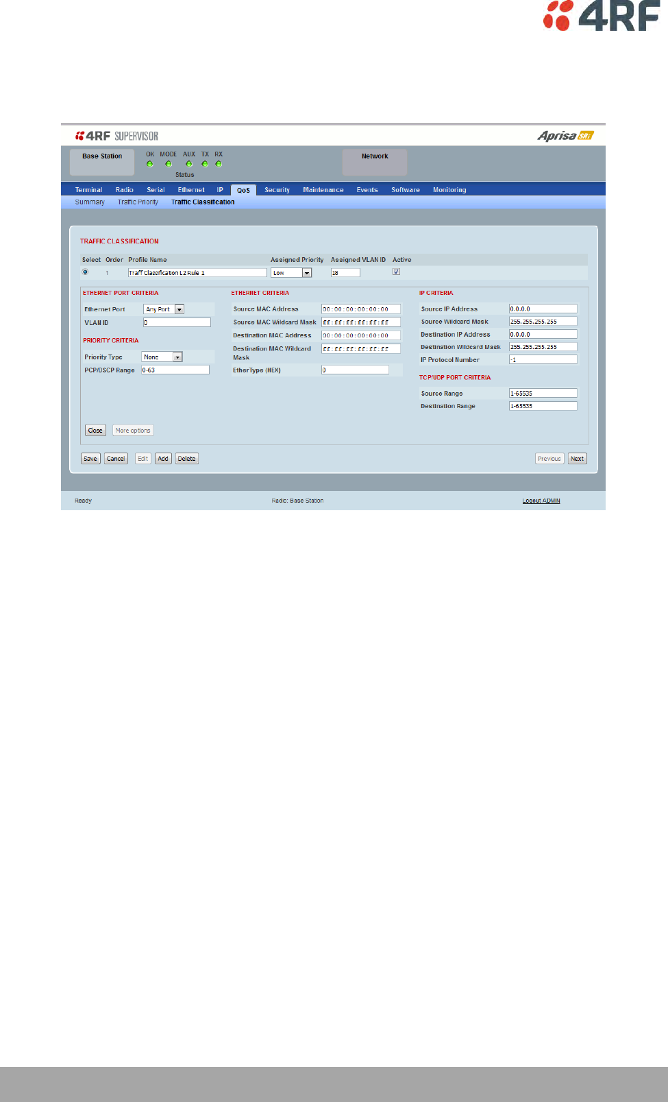
152 | Managing the Radio
Aprisa SRi User Manual 1.0.0
Click on More Options if more Layer 2/3/4 (Ethernet / IP / TCP or UDP) packet header fields are required
for the selected profile classification rule. This page describes all the possible fields that can be used for
the classification rules in bridge mode.
ETHERNET CRITERIA
Source MAC Address
This parameter sets the Layer 2 Ethernet packet header Source MAC Address field in the selected profile
classification rule in the format of ‘hh:hh:hh:hh:hh:hh’.
Source MAC Wildcard Mask
This parameter sets the wildcard mask of the ‘Source MAC Address’. If the Source MAC Address is set to
‘FF:FF:FF:FF:FF:FF’, all source MAC addresses will meet the criteria.
Destination MAC Address
This parameter sets the Layer 2 Ethernet packet header Destination MAC Address field in the selected
profile classification rule in the format of ‘hh:hh:hh:hh:hh:hh’.
Destination MAC Wildcard Mask
This parameter sets the wildcard mask of the ‘Destination MAC Address’. If the Destination MAC Address is
set to ‘FF:FF:FF:FF:FF:FF’, all destination MAC addresses will meet the criteria.

Managing the Radio | 153
Aprisa SRi User Manual 1.0.0
EtherType (Hex)
This parameter sets the Layer 2 Ethernet packet header EtherType field in the selected profile
classification rule. EtherType is a 16 bit (two octets) field in an Ethernet frame. It is used to indicate
which protocol is encapsulated in the payload of an Ethernet Frame.
EtherType Examples:
Protocol
EtherType Value
(Hexadecimal)
IPv4
0800
ARP
0806
IPv6
86DD
VLAN
8100
IP CRITERIA
Source IP Address
This parameter sets the Layer 3 IP packet header Source IP Address field in the selected profile
classification rule. This parameter is written in the standard IPv4 format of ‘xxx.xxx.xxx.xxx’.
Source IP Wildcard Mask
This parameter sets the wildcard mask applied to the ‘Source IP Address’. This parameter is written in the
standard IPv4 format of ‘xxx.xxx.xxx.xxx’.
0 means that it must be a match. If the wildcard mask is set to 0.0.0.0, the complete Source IP Address
will be evaluated for the classification rule.
If the wildcard mask is set to 0.0.255.255, the first 2 octets of the Source IP Address will be evaluated for
the classification rule.
If the wildcard mask is set to 255.255.255.255, none of the Source IP Address will be evaluated for the
classification rule.
Note: The wildcard mask operation is the inverse of subnet mask operation
Destination IP Address
This parameter sets the Layer 3 IP packet header Destination IP Address field in the selected profile
classification rule. This parameter is written in the standard IPv4 format of ‘xxx.xxx.xxx.xxx’.
Destination IP Wildcard Mask
This parameter sets the wildcard mask applied to the ‘Destination IP Address’. This parameter is written
in the standard IPv4 format of ‘xxx.xxx.xxx.xxx’.
0 means that it must be a match. If the wildcard mask is set to 0.0.0.0, the complete Destination IP
Address will be evaluated for the classification rule.
If the wildcard mask is set to 0.0.255.255, the first 2 octets of the Destination IP Address will be evaluated
for the classification rule.
If the wildcard mask is set to 255.255.255.255, none of the Destination IP Address will be evaluated for
the classification rule.
Note: The wildcard mask operation is the inverse of subnet mask operation
154 | Managing the Radio
Aprisa SRi User Manual 1.0.0
IP Protocol Number
This parameter sets the Layer 3 IP packet header ‘Protocol’ field in the selected profile classification rule.
This field defines the protocol used in the data portion of the IP datagram.
Protocol number Examples:
Protocol
Protocol value
(decimal)
ICMP
1
TCP
6
UDP
17
TCP / UDP PORT CRITERIA
Source Range
This parameter sets the Layer 4 TCP / UDP packet header Source Port or Source Port range field in the
selected profile classification rule. To specify a range, insert a dash between the ports e.g. 1000-2000. If
the source port range is set to 1-65535, traffic from any source port will meet the criteria.
Destination Range
This parameter sets the Layer 4 TCP / UDP packet header Destination Port or Destination Port range field
in the selected profile classification rules. To specify a range, insert a dash between the ports e.g. 1000-
2000. If the source port range is set to 1-65535, traffic from any source port will meet the criteria.
Examples for TCP / UDP Port Numbers:
Protocol
TCP / UDP Port #
(decimal)
Modbus
502
IEC 60870-5-104
2,404
DNP 3
20,000
SNMP
161
SNMP TRAP
162
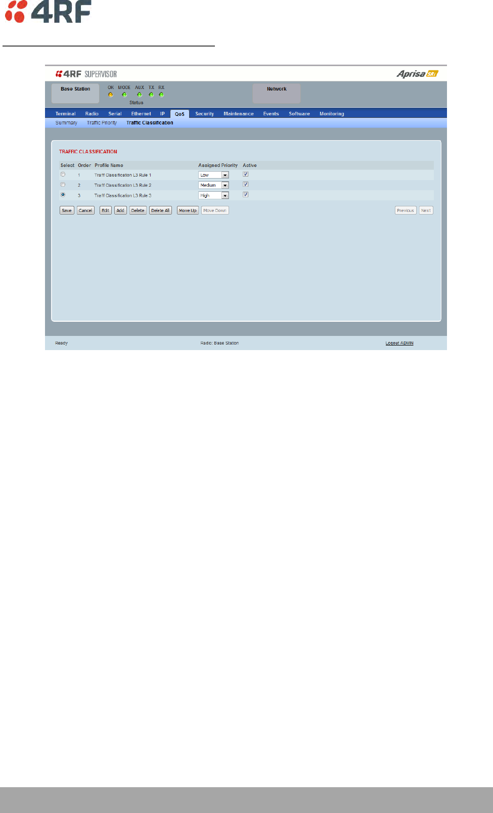
Managing the Radio | 155
Aprisa SRi User Manual 1.0.0
Router Mode Traffic Classification Settings
TRAFFIC CLASSIFICATION
Router Mode traffic classification settings provide mapping / assigning of profiles (set by rules to match a
specific traffic type) to a CoS / priority. The profile which is used to match to a specific traffic type will
be identified in the radio network by its associated CoS / priority to provide the appropriate QoS
treatment. CoS / Priority can be set to very high, high, medium, low priority.
Profile name
A free form field to enter the profile name with a maximum of 32 chars.
Assigned Priority
Traffic packets that match the applied profile rules will be assigned to the selected ‘assigned priority’
setting of Very High, High, Medium and Low. This field cannot be set to Don’t Care.
Active
Activated or deactivate the profile rule.

156 | Managing the Radio
Aprisa SRi User Manual 1.0.0
Controls
The Save button saves all profiles to the radio.
The Cancel button removes all changes since the last save or first view of the page if there has not been
any saves. This button will un-select all the Select radio buttons.
The Edit button will show the next screen for the selected profile where the profile can be configured.
This button will be disabled unless a profile is selected.
The Add button adds a new profile,
If no profile was selected then the new profile is added to the end of the list,
If a profile is selected the new profile is added after that profile.
The Delete button will delete the selected profile. The button will be disabled unless a profile has been
selected.
The Delete All button will delete all the profiles. A pop-up will ask if the action is correct. If the answer is
yes, then all profiles are deleted in SuperVisor. The Save button must be pressed to delete all the profiles
in the radio.
The Move up button will move the selected profile up one in the order of profiles
The Move Down button will move the selected profile down one in the order of profiles
The Previous button displays the previous page in the list of profiles. A pop up will be displayed if any
profile has been modified and not saved, preventing the previous page being displayed.
The Next button will display the next page in the list of profiles.
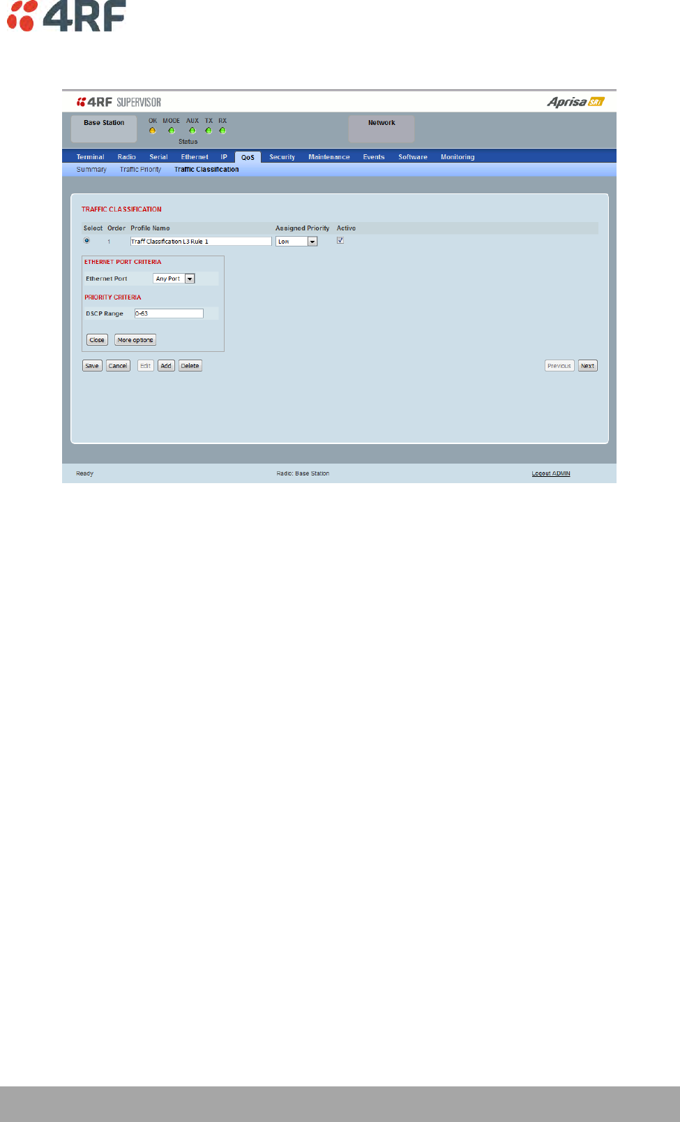
Managing the Radio | 157
Aprisa SRi User Manual 1.0.0
To edit a traffic classification, select the profile and click on the Edit button
ETHERNET PORT CRITERIA
Ethernet Port
Set the layer 1 Ethernet port number or all Ethernet ports in the selected profile classification rules.
PRIORITY CRITERIA
DSCP Range
Sets the DSCP priority value/s field in the selected profile classification rule. The value can be set to a
single priority or a single range (no multiple range are allowed), for example, priority value can be 46 (EF)
or a range of priority values like 10-14.
158 | Managing the Radio
Aprisa SRi User Manual 1.0.0
The following table shows the layer 3 packet IP header DSCP priority field values
DSCP Value
(Decimal)
DSCP Priority
46
EF (Expedited Forwarding)
10
AF11 (Assured Forwarding)
12
AF12
14
AF13
18
AF21
20
AF22
22
AF23
26
AF31
28
AF32
30
AF33
34
AF41
36
AF42
38
AF43
0
CS0/Best Effort (BE)
8
CS1 (Class Selector )
16
CS2
24
CS3
32
CS4
40
CS5
48
CS6
56
CS7
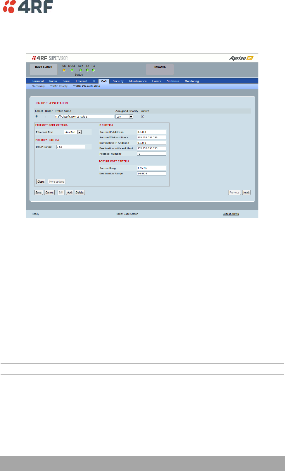
Managing the Radio | 159
Aprisa SRi User Manual 1.0.0
Click on More Options if more Layer 3/4 packet header fields are required for the selected profile
classification rule. This page describes all the possible fields that can be used for the classification rules in
router mode.
IP CRITERIA
Source IP Address
This parameter sets the Layer 3 packet IP header Source IP Address field in the selected profile
classification rules. This parameter is written in the standard IPv4 format of ‘xxx.xxx.xxx.xxx’.
Source IP Wildcard Mask
This parameter sets the wildcard mask applied to the ‘Source IP Address’. This parameter is written in the
standard IPv4 format of ‘xxx.xxx.xxx.xxx’.
0 means that it must be a match. If the wildcard mask is set to 0.0.0.0, the complete Source IP Address
will be evaluated for the classification rules.
If the wildcard mask is set to 0.0.255.255, the first 2 octets of the Source IP Address will be evaluated for
the classification rules.
If the wildcard mask is set to 255.255.255.255, none of the Source IP Address will be evaluated for the
classification rules.
Note: The wildcard mask operation is the inverse of subnet mask operation
Destination IP Address
This parameter sets the Layer 3 packet IP header Destination IP Address field in the selected profile
classification rules. This parameter is written in the standard IPv4 format of ‘xxx.xxx.xxx.xxx’.
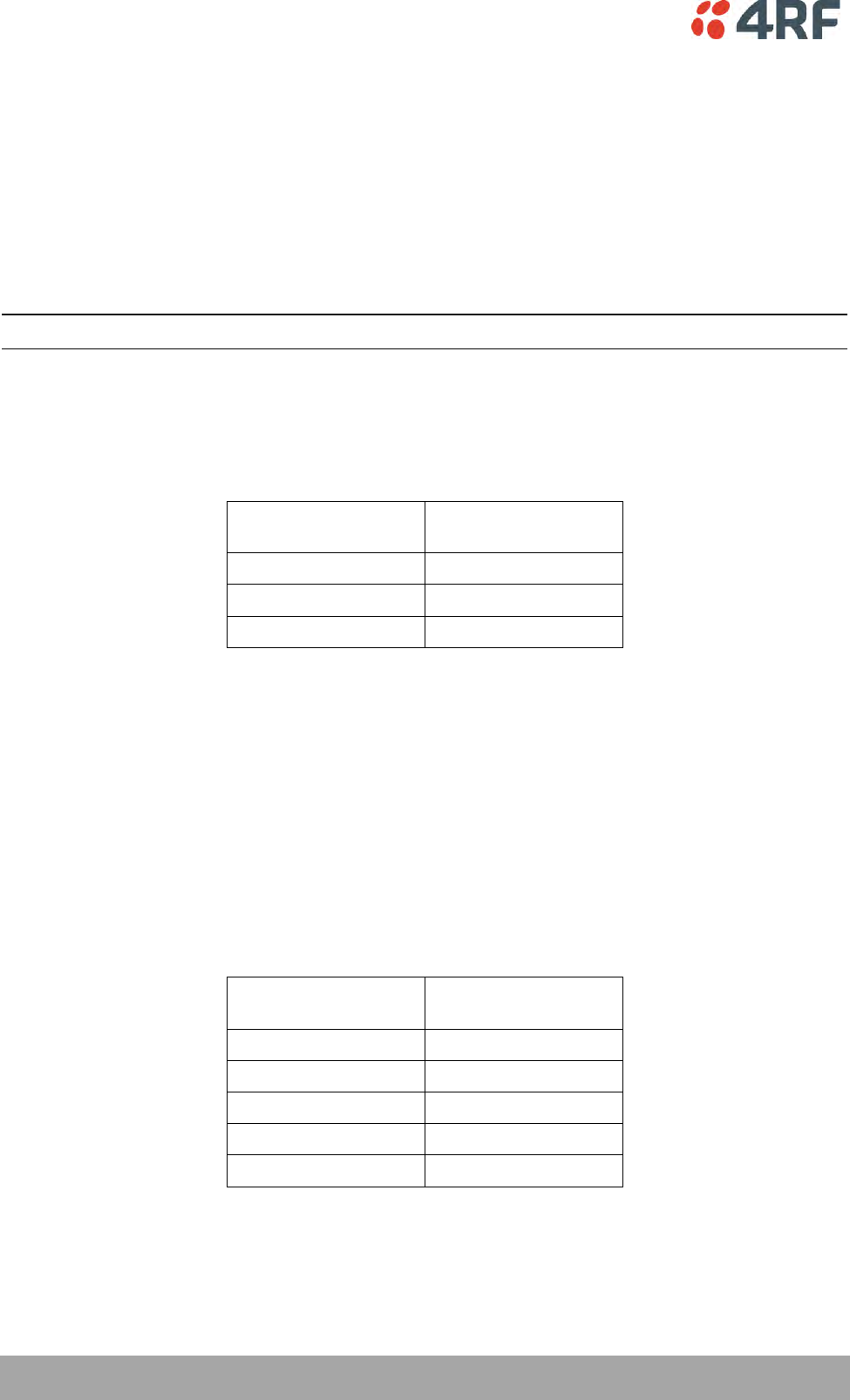
160 | Managing the Radio
Aprisa SRi User Manual 1.0.0
Destination IP Wildcard Mask
This parameter sets the wildcard mask applied to the ‘Destination IP Address’. This parameter is written
in the standard IPv4 format of ‘xxx.xxx.xxx.xxx’.
0 means that it must be a match. If the wildcard mask is set to 0.0.0.0, the complete Destination IP
Address will be evaluated for the classification rules.
If the wildcard mask is set to 0.0.255.255, the first 2 octets of the Destination IP Address will be evaluated
for the classification rules.
If the wildcard mask is set to 255.255.255.255, none of the Destination IP Address will be evaluated for
the classification rules.
Note: The wildcard mask operation is the inverse of subnet mask operation
Protocol Number
This parameter sets the Layer 3 IP packet header ‘Protocol’ field in the selected profile classification rule.
This field defines the protocol used in the data portion of the IP datagram.
Protocol number Examples:
Protocol
Protocol value
(decimal)
ICMP
1
TCP
6
UDP
17
TCP / UDP Port Criteria
Source Range
This parameter sets the Layer 4 TCP / UDP packet header Source Port or Source Port range field in the
selected profile classification rule. To specify a range, insert a dash between the ports e.g. 1000-2000. If
the source port range is set to 1-65535, traffic from any source port will meet the criteria.
Destination Range
This parameter sets the Layer 4 TCP / UDP packet header Destination Port or Destination Port range field
in the selected profile classification rule. To specify a range, insert a dash between the ports e.g. 1000-
2000. If the source port range is set to 1-65535, traffic from any source port will meet the criteria.
Examples for TCP / UDP Port Numbers:
Protocol
TCP / UDP Port #
(decimal)
Modbus
502
IEC 60870-5-104
2,404
DNP 3
20,000
SNMP
161
SNMP TRAP
162
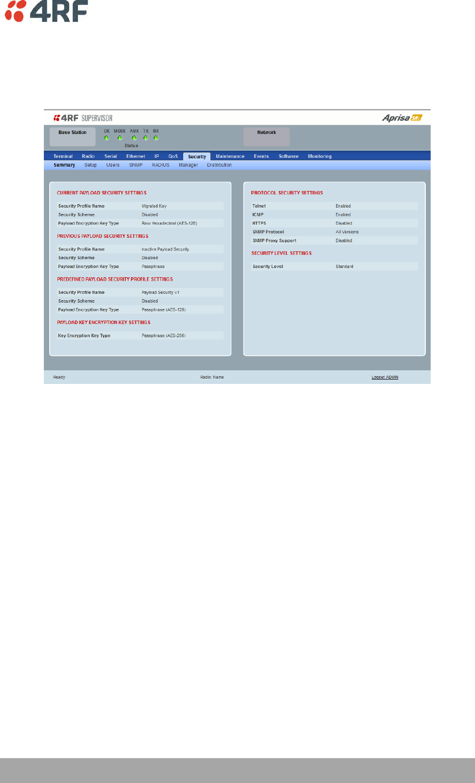
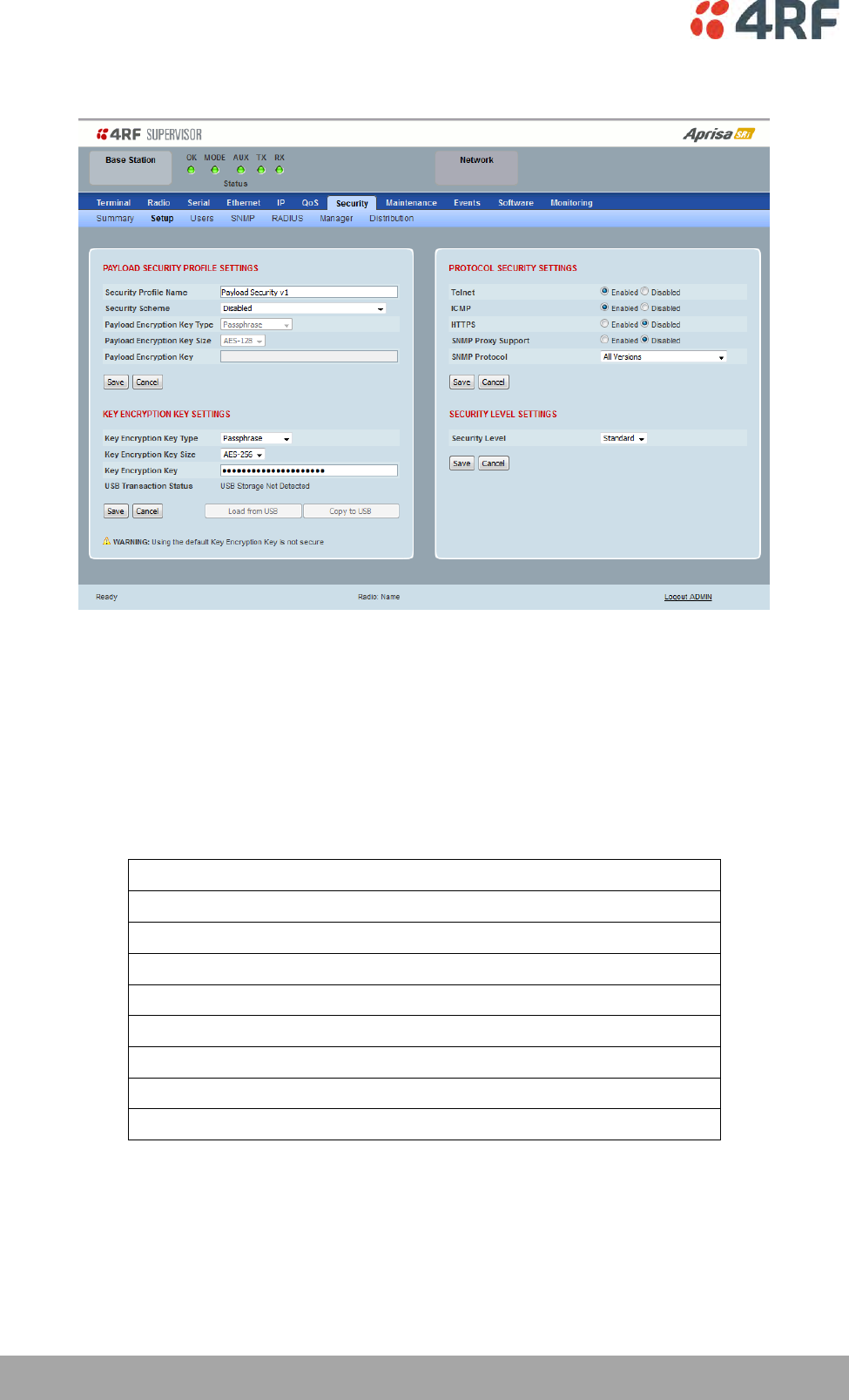
162 | Managing the Radio
Aprisa SRi User Manual 1.0.0
Security > Setup
PAYLOAD SECURITY PROFILE SETTINGS
Security Profile Name
This parameter enables the user to predefine a security profile with a specified name.
Security Scheme
This parameter sets the security scheme to one of the values in the following table:
Security Scheme
Disabled (No encryption and no Message Authentication Code)
AES Encryption + CCM Authentication 128 bit
AES Encryption + CCM Authentication 64 bit
AES Encryption + CCM Authentication 32 bit
AES Encryption only
CCM Authentication 128 bit
CCM Authentication 64 bit
CCM Authentication 32 bit
The default setting is Disabled.

Managing the Radio | 163
Aprisa SRi User Manual 1.0.0
Payload Encryption Key Type
This parameter sets the Payload Encryption Key Type:
Option
Function
Pass Phrase
Use the Pass Phrase password format for standard security.
Raw Hexadecimal
Use the Raw Hexadecimal key format for better security. It
must comply with the specified encryption key size e.g. if
Encryption Type to AES128, the encryption key must be 16
bytes (32 chars)
The default setting is Pass Phrase.
Payload Encryption Key Size
This parameter sets the Encryption Type to AES128, AES192 or AES256. The default setting is AES128.
The higher the encryption size the better the security.
Payload Encryption Key
This parameter sets the Payload Encryption password. This key is used to encrypt the payload.
Pass Phrase
Good password policy:
contains at least eight characters, and
contains at least one upper case letter, and
contains at least one lower case letter, and
contains at least one digit or another character such as @+... , and
is not a term in a familiar language or jargon, and
is not identical to or derived from the accompanying account name, from personal characteristics
or from information from one’s family/social circle, and
is easy to remember, for instance by means of a key sentence
Raw Hexadecimal
The Raw Hexadecimal key must comply with the specified encryption key size e.g. if Encryption Type to
AES128, the encryption key must be 16 bytes (32 chars).
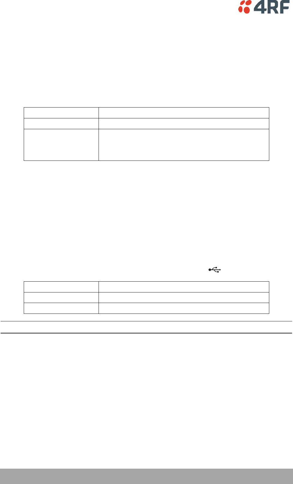
164 | Managing the Radio
Aprisa SRi User Manual 1.0.0
KEY ENCRYPTION KEY SETTINGS
The Key Encryption Key provides the ability to encrypt the Payload Encryption Key so it can be safely
transmitted over the radio link to remote radios.
The Key Encryption Key Type, Key Encryption Key Size and Key Encryption Key must be the same on all
radios in the network.
Key Encryption Key Type
This parameter sets the Payload Encryption Key Type:
Option
Function
Pass Phrase
Use the Pass Phrase password format for standard security.
Raw Hexadecimal
Use the Raw Hexadecimal key format for better security. It
must comply with the specified encryption key size
e.g. if Encryption Type to AES128, the encryption key must
be 16 bytes (32 chars)
The default setting is Pass Phrase.
Key Encryption Key Size
This parameter sets the Encryption Type to AES128, AES192 or AES256. The default setting is AES128.
The higher the encryption type the better the security.
Key Encryption Key
This parameter sets the Key Encryption Key. This is used to encrypt the payload encryption key.
USB Transaction Status
This parameter shows if a USB flash drive is plugged into the radio host port .
Option
Function
USB Storage Not Detected
A USB flash drive is not plugged into the radio host port.
USB Storage Detected
A USB flash drive is plugged into the radio host port.
Note: Some brands of USB flash drives may not work with 4RF radios.
Controls
The ‘Save’ button saves the Key Encryption Key settings to the radio. If the Security Level is set to Strong
(see ‘Security Level’ on page 170), this button will be grayed out.
The ‘Load From USB’ button loads the Key Encryption Key settings from the USB flash drive. If a USB flash
drive is not detected, this button will be grayed out
The ‘Copy To USB’ button copies the Key Encryption Key settings to a file called ‘asrkek.txt’ on the USB
flash drive. This settings file can be used to load into other radios. If a USB flash drive is not detected or
the Security Level is set to Strong (see ‘Security Level’ on page 170), this button will not be shown.

Managing the Radio | 165
Aprisa SRi User Manual 1.0.0
Key Encryption Key Summary
The security of over-the-air-rekeying depends on a truly random Key Encryption Key. This is why the use
of a Raw Hexadecimal key is recommended as a plain text phrase based on known spelling and grammar
constructs is not very random. The default Key Encryption Key is provided only to allow testing of the
security mechanism and is not intended for operational use. Using the default Key Encryption Key
undermines the security of the AES payload encryption because an attacker using the default Key
Encryption Key would immediately recover the AES payload key after the first over-the-air-rekeying event.
When the Security Level is set to Strong, various protections are applied to the Key Encryption Key setting
to prevent tampering. In addition, the Key Encryption Key Type, Key Encryption Key Size, and the Key
Encryption Key itself are all loaded from a customer prepared USB key. This is a one way operation to
prevent key recovery from radios. While the ability to save a Key Encryption Key to USB exists in Standard
Security Level, the Strong Security Level Key Encryption Key is not compromised because the Strong Key
Encryption Key is not the same as the Standard Security Level Key Encryption Key.
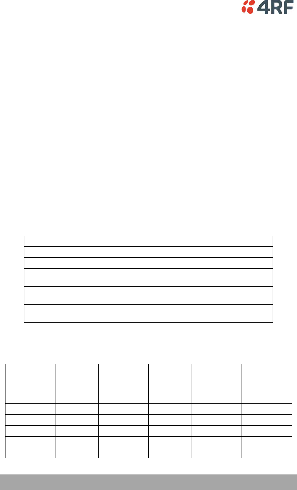
166 | Managing the Radio
Aprisa SRi User Manual 1.0.0
PROTOCOL SECURITY SETTINGS
Telnet option
This parameter option determines if you can manage the radio via a Telnet session. The default setting is
disabled.
ICMP option (Internet Control Message Protocol)
This parameter option determines whether the radio will respond to a ping. The default setting is
disabled.
HTTPS option
This parameter option determines if you can manage the radio via a HTTPS session (via a Browser). The
default setting is enabled.
SNMP Proxy Support
This parameter option enables an SNMP proxy server in the base station. This proxy server reduces the
radio link traffic during SNMP communication to remote stations. This option applies to the base station
only. The default setting is disabled.
This option can also be used if the radio has Serial Only interfaces.
SNMP Protocol
This parameter sets the SNMP Protocol:
Option
Function
Disabled
All SNMP functions are disabled.
All Versions
Allows all SNMP protocol versions.
SNMPv3 Only
Only SNMPv3 transactions will be accepted including
authenticated or encrypted transactions
SNMPv3 With
Authentication Only
Only SNMPv3 transactions authenticated using HMAC-MD5 or
HMAC-SHA will be accepted (as per table below).
SNMPv3 With Encryption
Only
Only SNMPv3 transactions with an encrypted type of DES or
AES will be accepted (as per table below).
The default setting is All Versions.
The default SNMPv3 with Authentication User Details provided are:
User Name
Encryption
Type
Authentication
Type
Context
Name
Authentication
Passphrase
Encryption
Passphrase
noAuthUser
-
-
noAuth
noAuthUser
noAuthUser
desUserMD5
DES
MD5
priv
desUserMD5
desUserMD5
desUserSHA
DES
SHA
priv
desUserSHA
desUserSHA
authUserMD5
-
MD5
auth
authUserMD5
authUserMD5
authUserSHA
-
SHA
auth
authUserSHA
authUserSHA
privUserMD5
AES
MD5
priv
privUserMD5
privUserMD5
privUserSHA
AES
SHA
priv
privUserSHA
privUserSHA

Managing the Radio | 167
Aprisa SRi User Manual 1.0.0
SNMPv3 Authentication Passphrase
The SNMPv3 Authentication Passphrase can be changed via the SNMPv3 secure management protocol
interface (not via SuperVisor).
When viewing / managing the details of the users via SNMPv3, the standard SNMP-USER-BASED-SM-MIB
interface is used. This interface can be used to change the SNMPv3 Authentication Passphrase of the users.
The SNMPv3 Authentication Passphrase of a user required to be changed cannot be changed by the same
user i.e. a different user must be used for the transactions.
Generate New Keys from SNMPv3 USM User Passphrases
Net-SNMP is a suite of open source software for using and deploying the SNMP protocol. Similar
functionality is built into many commercial SNMP managers.
This next step of loading the Aprisa SRi radios with keys generated from USM user passphrases requires the
SNMPv3 USM Management utility provided as part of NET-SNMP.
The utility is called ‘snmpusm’. It provides a range of commands including the management of changing
passwords for SNMPv3 users. In order to use this utility, the user will need to install NET-SNMP on a Linux
(or Windows®) or machine. The examples below are from the Linux environment. This tool automatically
obtains the engine ID from the target radio before generating the keys and loading them into the target.
To change a user authentication passphrase:
The following are examples of:
Changing the privUserSHA user encryption key / password from privUserSHA to privUserSHANew:
c:\usr\bin>snmpusm -v 3 -u privUserSHA -n priv -l authPriv -a SHA -A privUserSHA -x AES -X
privUserSHA -Cx 172.17.70.17 passwd privUserSHA privUserSHANew
Changing the privUserSHA user authentication key / password from privUserSHA to privUserSHANew:
c:\usr\bin>snmpusm -v 3 -u privUserSHA -n priv -l authPriv -a SHA -A privUserSHA -x AES -X
privUserSHANew -Ca 172.17.70.17 passwd privUserSHA privUserSHANew
Changing the desUserSHA user encryption key / password from desUserSHA to desUserSHANew:
c:\usr\bin>snmpusm -v 3 -u desUserSHA -n priv -l authPriv -a SHA -A desUserSHA -x DES -X desUserSHA
-Cx 172.17.70.17 passwd desUserSHA desUserSHANew
Changing the desUserSHA user authentication key / password from desUserSHA to desUserSHANew:
c:\usr\bin>snmpusm -v 3 -u desUserSHA -n priv -l authPriv -a SHA -A desUserSHA -x DES -X
desUserSHANew -Ca 172.17.70.17 passwd desUserSHA desUserSHANew
Changing the privUserMD5 user encryption key / password from privUserMD5 to privUserMD5New:
c:\usr\bin>snmpusm -v 3 -u privUserMD5 -n priv -l authPriv -a MD5 -A privUserMD5 -x AES -X
privUserMD5 -Cx 172.17.70.17 passwd privUserMD5 privUserMD5New
Changing the privUserMD5 user authentication key / password from privUserMD5 to privUserMD5New:
c:\usr\bin>snmpusm -v 3 -u privUserMD5 -n priv -l authPriv -a MD5 -A privUserMD5 -x AES -X
privUserMD5New -Ca 172.17.70.17 passwd privUserMD5 privUserMD5New

168 | Managing the Radio
Aprisa SRi User Manual 1.0.0
Changing the desUserMD5 user encryption key / password from desUserMD5 to desUserMD5New:
c:\usr\bin>snmpusm -v 3 -u desUserMD5 -n priv -l authPriv -a MD5 -A desUserMD5 -x DES -X
desUserMD5 -Cx 172.17.70.17 passwd desUserMD5 desUserMD5New
Changing the desUserMD5 user authentication key / password from desUserMD5 to desUserMD5New:
c:\usr\bin>snmpusm -v 3 -u desUserMD5 -n priv -l authPriv -a MD5 -A desUserMD5 -x DES -X
desUserMD5New -Ca 172.17.70.17 passwd desUserMD5 desUserMD5New
Changing the authUserSHA user authentication key / password from authUserSHA to authUserSHANew:
c:\usr\bin>snmpusm -v 3 -u authUserSHA -n auth -l authNoPriv -a SHA -A authUserSHA -Ca
172.17.70.17 passwd authUserSHA authUserSHANew
Changing the authUserMD5 user authentication key / password from authUserMD5 to authUserMD5New:
c:\usr\bin>snmpusm -v 3 -u authUserMD5 -n auth -l authNoPriv -a MD5 -A authUserMD5 -Ca
172.17.70.17 passwd authUserMD5 authUserMD5New
Notes
-Cx option is to change the Encryption key/password
-Ca option is to change the Authentication key/password
Other information on this utility can be obtained from the utility command help itself or online
Summary
It is necessary to record the new passphrases loaded into the Aprisa SRi radios and then load the
passphrases into the SNMP manager. There is a separate passphrase for the two supported forms of
authentication (MD5 and SHA1) only as well as the two forms of authentication used in combination the
two forms of encryption (DES and AES). It is vital to change all passphrases even if the depreciated
mechanism are not used (MD5 and DES) otherwise an attacker could still use the default passphrases.

Managing the Radio | 169
Aprisa SRi User Manual 1.0.0
Reset Unknown Passphrases with the Command Line Interface
As it is not possible for users to read previously set passphrases, a CLI command is available from Aprisa
SRi software release 1.4.0 to ‘reset’ the SNMPv3 USM users back to defaults.
Note: USM users are not related to CLI and SuperVisor users. This command will only be accessible to the
CLI ‘admin’ user logins.
To reset unknown passphrases:
1. Telnet into each radio in the network and via the CLI reset the passphrases
2. Login to the radio with:
Login: admin
Password: *********
3. Set all SNMP3 users to default values with the ‘snmpusm reset’ command (see ‘SNMP3 users to default
values’ below for the list of default values).
4. Reboot the radio with the ‘reboot’ command.
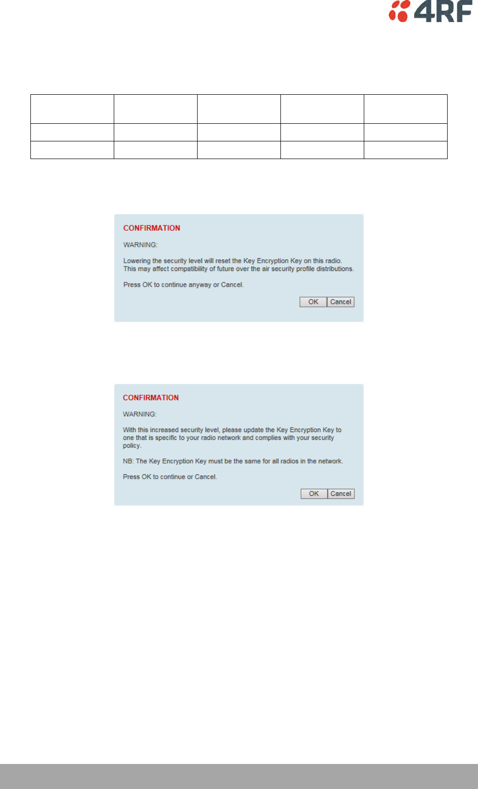
170 | Managing the Radio
Aprisa SRi User Manual 1.0.0
SECURITY LEVEL SETTINGS
Security Level
This parameter sets the Security Level active security features. The default setting is Standard.
Option
Payload
Encryption
HTTPS
SNMPv3
USB KEK Only
Standard
Strong
If the Security Level is reduced, there will be a pop up message warning that Key Encryption Key will be
reset to the default value.
If the Security Level is increased, there will be a pop up message reminding user to enter a new Key
Encryption Key.
If the Security Level is set to Strong, the ‘Save’ button will be grayed out and the ‘Copy To USB’ button
will not be shown.
SNMPv3 Context Addressing
SNMPv3 is not user configurable and user can use this option with any NMS. The radio SNMP management
interface supports SNMPv3/2 context addressing. The SNMv3 context addressing allows the user to use
secure SNMPv3 management while improving NMS performance.
A NMS (Network Management System) can access any remote radio directly by using its IP address or via
the base / master station SNMPv3 context addressing. The SNMPv3 context addressing can compress the
SNMPv3 management traffic OTA (Over The Air) to the remote station by up to 90% relative to direct OTA
SNMPv3 access to remote station, avoiding the radio narrow bandwidth traffic loading.
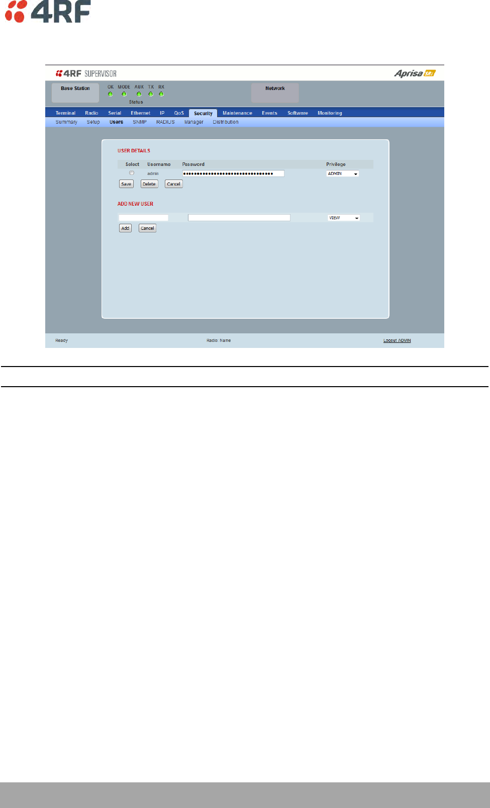
Managing the Radio | 171
Aprisa SRi User Manual 1.0.0
Security > Users
Note: You must login with ‘admin’ privileges to add, disable, delete a user or change a password.
USER DETAILS
Shows a list of the current users setup in the radio.
ADD NEW USER
To add a new user:
1. Enter the Username.
A username can be up to 32 characters but cannot contain back slashes, forward slashes, spaces, tabs,
single or double quotes. Usernames are case sensitive.
2. Enter the Password.
A password can be 8 to 32 printable characters but cannot contain a tab. Passwords are case sensitive.
Good password policy:
contains at least eight characters, and
contains at least one upper case letter, and
contains at least one lower case letter, and
contains at least one digit or another character such as !@#$%^&(){}[]<>... , and
is not a term in a familiar language or jargon, and
is not identical to or derived from the accompanying account name, from personal characteristics
or from information from one’s family/social circle, and
is easy to remember, for instance by means of a key sentence
3. Select the User Privileges

172 | Managing the Radio
Aprisa SRi User Manual 1.0.0
There are four pre-defined User Privilege settings to allocate access rights to users. These user privileges
have associated default usernames and passwords of the same name.
The default login is ‘admin’.
This login has full access to all radio parameters including the ability to add and change users. There can
only be a maximum of two usernames with admin privileges and the last username with admin privileges
cannot be deleted.
User
Privilege
Default
Username
Default
Password
User Privileges
View
view
view
Users in this group can only view the summary
pages.
Technician
technician
technician
Users in this group can view and edit parameters
except Security > Users and Security > Setup.
Engineer
engineer
engineer
Users in this group can view and edit parameters
except Security > Users.
Admin
admin
admin
Users in this group can view and edit all
parameters.
See ‘SuperVisor Menu Access’ on page 76 for the list of SuperVisor menu items versus user privileges.
4. Click ‘Add’
To delete a user:
1. Select Terminal Settings > Security > Users
2. Click on the Select button for the user you wish to delete.
3. Click ‘Delete
To change a Password:
1. Select Terminal Settings > Security > Users
2. Click on the Select button for the user you wish to change the Password.
3. Enter the Password.
A password can be 8 to 32 characters but cannot contain back slashes, forward slashes, spaces, tabs,
single or double quotes.
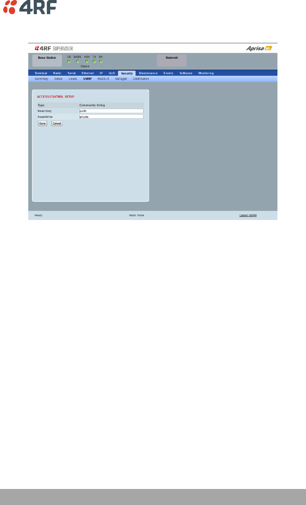
Managing the Radio | 173
Aprisa SRi User Manual 1.0.0
Security > SNMP
In addition to web-based management (SuperVisor), the network can also be managed using the Simple
Network Management Protocol (SNMP) using any version of SNMP v1/2/3. MIB files are supplied, and these
can be used by a dedicated SNMP Manager, such as Castle Rock’s SNMPc, to access most of the radio’s
configurable parameters.
For communication between the SNMP manager and the radio, Access Controls and Community strings
must be set up as described in the following sections.
A SNMP Community String is used to protect against unauthorized access (similar to a password). The
SNMP agent (radio or SNMP manager) will check the community string before performing the task
requested in the SNMP message.
ACCESS CONTROL SETUP
A SNMP Access Control is the IP address of the radio used by an SNMP manager or any other SNMP device
to access the radio. The Aprisa SRi allows access to the radio from any IP address.
Read Only
The default Read Only community string is public.
Read Write
The default ReadWrite community string is private.

174 | Managing the Radio
Aprisa SRi User Manual 1.0.0
SNMP Manager Setup
The SNMP manager community strings must be setup to access the base station and remote stations.
To access the base station, a community string must be setup on the SNMP manager the same as the
community string setup on the radio (see ‘Security > SNMP’ on page 173).
SNMP access to remote stations can be achieved by using the radio’s IP address and the normal community
string or by proxy in the base station.
SNMP Access via Base Station Proxy
To access the remote stations via the base station proxy, the community strings must be setup on the
SNMP manager in the format:
ccccccccc:bbbbbb
Where:
ccccccccc is the community string of the base station
and
bbbbbb is the last 3 bytes of the remote station MAC address (see ‘Network Status > Network Table’
on page 246).
The SNMP Proxy Support must be enabled for this method of SNMP access to operate (see ‘SNMP Proxy
Support’ on page 166).
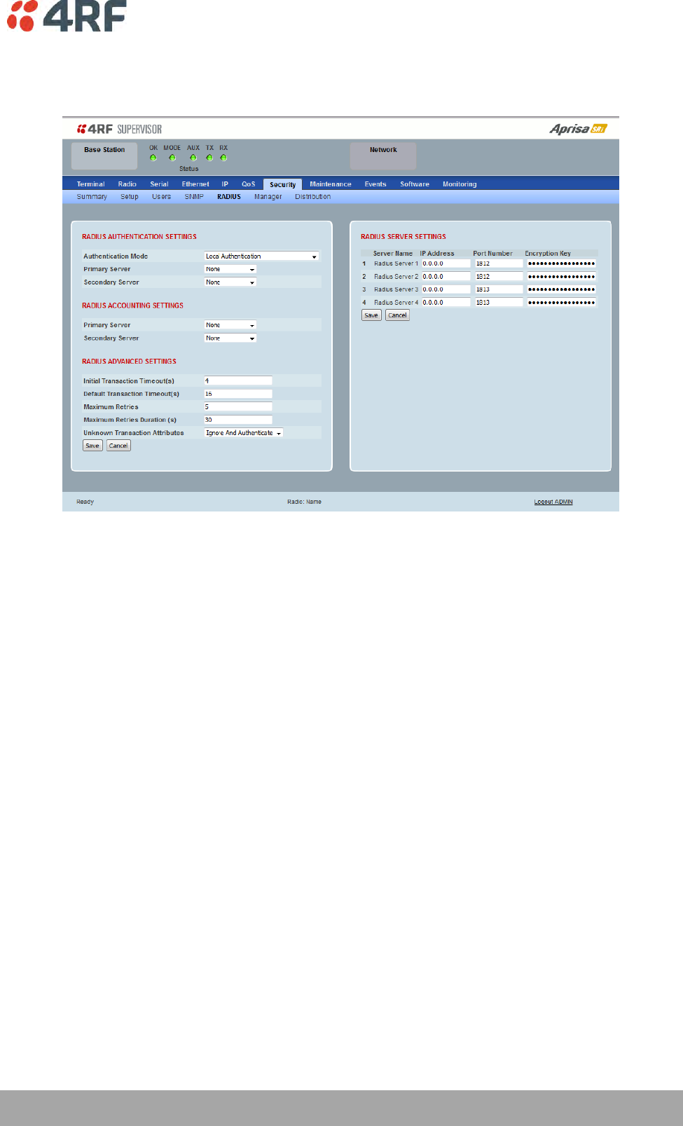
Managing the Radio | 175
Aprisa SRi User Manual 1.0.0
Security > RADIUS
This page displays the current settings for the Security RADIUS.
RADIUS - Remote Authentication Dial In User Service
RADIUS is a client / server system that secures the radio link against unauthorized access. It is based on
open standard RFCs: RFC 2865/6, 5607, 5080 and 2869. It is used for remote user Authorization,
Authentication and Accounting.
When a user logs into a radio with RADIUS enabled, the user’s credentials are sent to the RADIUS server
for authentication of the user.
Transactions between the RADIUS client and RADIUS server are authenticated through the use of a shared
secret, which is never sent over the network.
For a RADIUS server to respond to the radio, it must configured with and respond to the following
Management-Privilege-level attributes:
Admin Level = 4
Technician Level = 2
Viewer Level = 1
A RADIUS server can act as a proxy client to other RADIUS servers or other kinds of authentication servers.

176 | Managing the Radio
Aprisa SRi User Manual 1.0.0
RADIUS AUTHENTICATION SETTINGS
Authentication Mode
This parameter sets the Authentication Mode.
Option
Function
Local Authentication
No radius Authentication – allows any local user privilege
Radius Authentication
Only radius Authentication – no local user privilege
Radius Authentication
and Local admin
Uses radius Authentication if it is available.
If radius Authentication is not available, uses local Admin login
Radius Then Local
Authentication
If the user is not authenticated in the radius server, it allows any
local user privilege.
Local Then Radius
Authentication
If the user is not allowed in the local user privilege, radius
authentication is used.
Primary Server
This parameter sets which radius server is used as the primary server for authentication. Select one of the
possible authentication servers setup in Radius Server Settings.
Secondary Server
This parameter sets which radius server is used as the secondary server for authentication. Select one of
the possible authentication servers setup in Radius Server Settings.
RADIUS ACCOUNTING SETTINGS
Primary Server
This parameter sets which radius server is used as the primary server for accounting (log of user activity).
Select one of the possible accounting servers setup in Radius Server Settings.
Secondary Server
This parameter sets which radius server is used as the secondary server for accounting. Select one of the
possible accounting servers setup in Radius Server Settings.
RADIUS ADVANCED SETTINGS
Initial Transaction Timeouts (IRT) (seconds)
This parameter sets the initial time to wait before the retry mechanism starts when the server is not
responding.
Default Transaction Timeouts (MRT) (seconds)
This parameter sets the maximum time between retries.
Maximum Retries (MRC)
This parameter sets the maximum number of retry attempts when the server is not responding.

Managing the Radio | 177
Aprisa SRi User Manual 1.0.0
Maximum Retries Duration (MRD) (seconds)
This parameter sets the maximum duration it will attempt retries when the server is not responding.
Unknown Transaction Attributes
This parameter sets the radio’s response to unknown attributes received from the radius server.
Option
Function
Ignore and Authenticate
Ignore the unknown attributes and accept the authentication
received from the radius server
Reject and Deny
Reject the authentication received from the radius server
RADIUS SERVER SETTINGS
Server Name
You can enter up to four radius servers 1-4.
IP Address
The IP address of the Radius server.
Port Number
The Port Number of the Radius server. RADIUS uses UDP as the transport protocol.
UDP port 1812 is used for authentication / authorization
UDP port 1813 is used for accounting.
Old RADIUS servers may use unofficial UDP ports 1645 and 1646.
Encryption Key
The password of the Radius server.
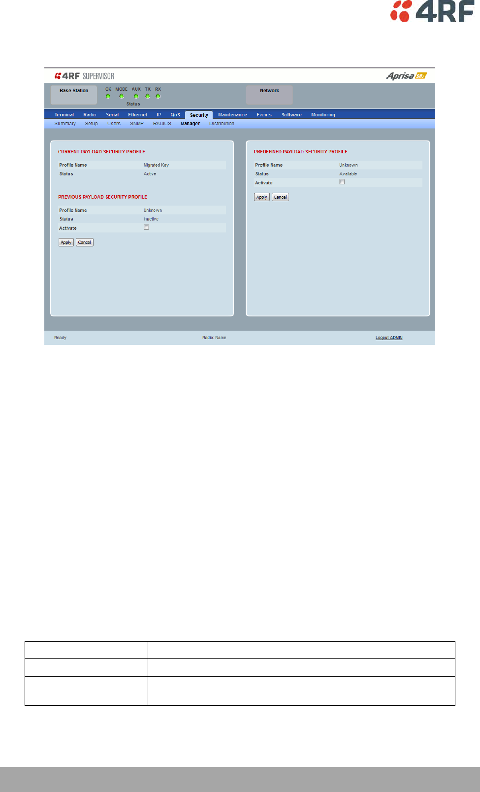
178 | Managing the Radio
Aprisa SRi User Manual 1.0.0
Security > Manager
CURRENT PAYLOAD SECURITY PROFILE
Profile Name
This parameter shows the predefined security profile active on the radio.
Status
This parameter displays the status of the predefined security profile on the radio (always active).
PREVIOUS PAYLOAD SECURITY PROFILE
Profile Name
This parameter displays the security profile that was active on the radio prior to the current profile being
activated.
Status
This parameter displays the status of the security profile that was active on the radio prior to the current
profile being activated.
Option
Function
Active
The security profile is active on the radio.
Inactive
The security profile is not active on the radio but could be
activated if required.

Managing the Radio | 179
Aprisa SRi User Manual 1.0.0
Activate
This parameter activates the previous security profile (restores to previous version).
PREDEFINED PAYLOAD SECURITY PROFILE
Profile Name
This parameter displays the new security profile that could be activated on the radio or distributed to all
remote radios with Security > Distribution.
Status
This parameter displays the status of the new security profile.
Option
Function
Unavailable
A predefined security profile is not available on this radio.
To create a predefined security profile, go to ‘Security > Setup’ on
page 162.
Available
A predefined security profile is available on this radio for
distribution and activation.
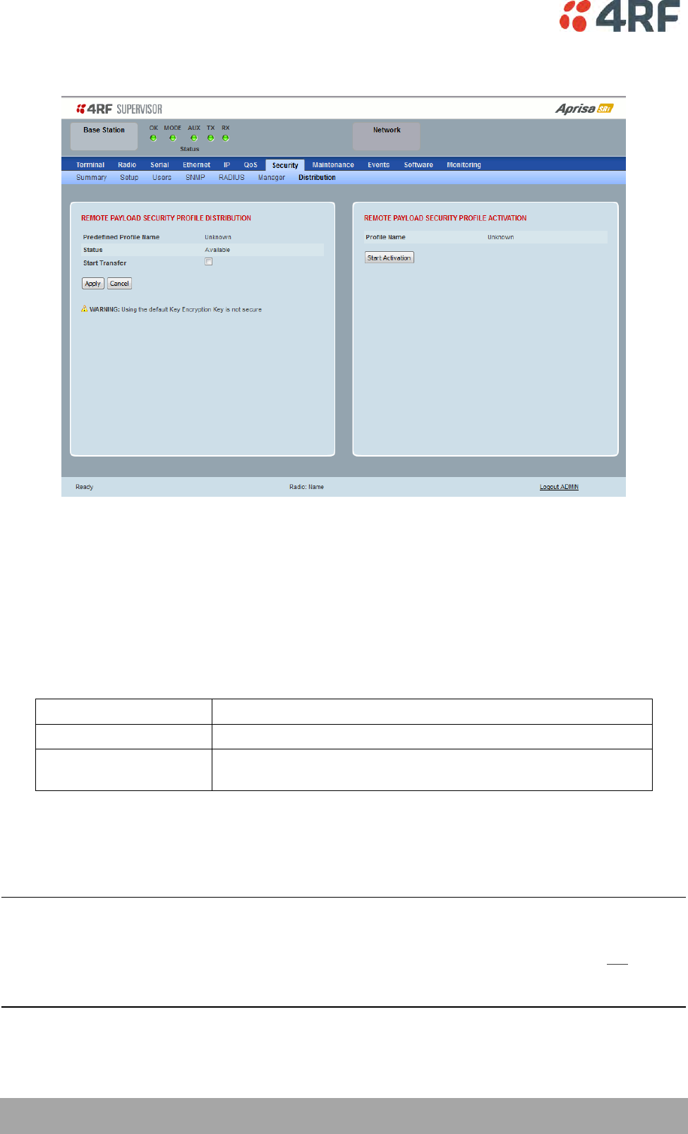
180 | Managing the Radio
Aprisa SRi User Manual 1.0.0
Security > Distribution
REMOTE PAYLOAD SECURITY PROFILE DISTRIBUTION
Predefined Profile Name
This parameter displays the predefined security profile available for distribution to remote stations.
Status
This parameter shows if a predefined security profile is available for distribution to remote stations.
Option
Function
Unavailable
A predefined payload security profile is not available on this radio.
Available
A predefined payload security profile is available on this radio for
distribution and activation.
Start Transfer
This parameter when activated distributes (broadcasts) the new payload security profile to all remote
stations in the network.
Note: The distribution of the payload security profile to remote stations does not stop customer traffic
from being transferred.
Payload security profile distribution traffic is classified as ‘management traffic’ but does not use the
Ethernet management priority setting. Security profile distribution traffic priority has a fixed priority
setting of ‘very low’.
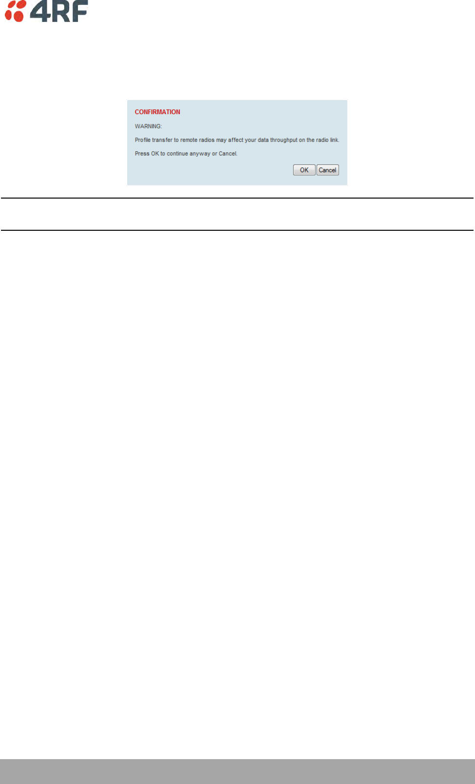
Managing the Radio | 181
Aprisa SRi User Manual 1.0.0
To distribute the payload security profile to remote stations:
This process assumes that a payload security profile has been setup (see ‘Security > Setup’ on page 162).
1. Tick Start Transfer and click Apply.
Note: This process could take up to 1 minute per radio depending on channel size, Ethernet Management
Priority setting and the amount of customer traffic on the network.
2. When the distribution is completed, activate the software with the Remote Payload Security Profile
Activation.
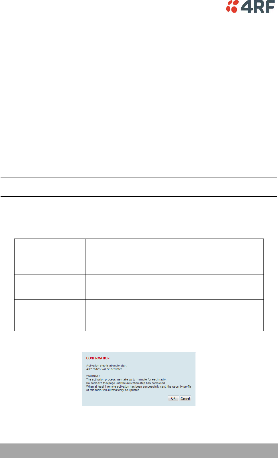
182 | Managing the Radio
Aprisa SRi User Manual 1.0.0
REMOTE PAYLOAD SECURITY PROFILE ACTIVATION
When the security profile has been distributed to all the remote stations, the security profile is then
activated in all the remote stations with this command.
The base station will always attempt to distribute the profile successfully. This broadcast distribution has
its own retry mechanism. The user can find out if all the remote radios have the latest profile when the
managed activation process is attempted. A pop up confirmation will be shown by SuperVisor with
relevant information and the user can decide to proceed or not. The user can attempt to redistribute
again if needed. If the decision is made to continue, on completion of the activation process,
communication with the remote radios that did not have the new security profile will be lost.
Predefined Profile Name
This parameter displays the predefined security profile available for activation on all remote stations.
To activate the security profile in remote stations:
This process assumes that a security profile has been setup into the base station (see ‘Security > Setup’ on
page 162) and distributed to all remote radios in the network.
Note: Do not navigate SuperVisor away from this page during the activation process (SuperVisor can lose
PC focus).
1. Click Start Activation
The remote stations will be polled to determine which radios require activation:
Result
Function (X of Y)
Remote Radios Polled for
New Profile
X is the number of radios polled to determine if the radio contains
the new security profile.
Y is the number of remote radios registered with the base station.
Remote Radios Activated
X is the number of radios activated.
Y is the number of radios with the new security profile requiring
activation.
Remote Radios On New
Profile
X is the number of radios activated and on the new security
profile.
Y is the number of radios with the new security profile that have
been activated.
When the activation is ready to start:
3. Click on ‘OK’ to start the activation process or Cancel to quit.
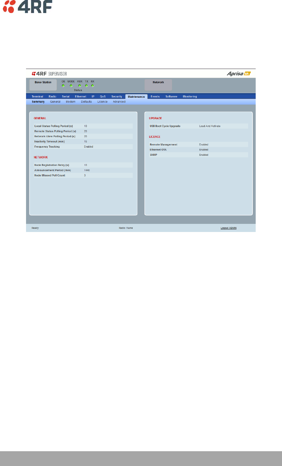
Managing the Radio | 183
Aprisa SRi User Manual 1.0.0
Maintenance
Maintenance > Summary
This page displays the current settings for the Maintenance parameters.
GENERAL
Local Status Polling Period (sec)
This parameter displays the rate at which SuperVisor refreshes the Local Radio alarm LED states and RSSI
value.
Remote Status Polling Period (sec)
This parameter displays the rate at which SuperVisor refreshes the Remote Radio alarm LED states and
RSSI value.
Network View Polling Period (sec)
This parameter displays the rate at which SuperVisor polls all remote radios for status and alarm
reporting.
Inactivity Timeout (min)
This parameter displays the period of user inactivity before SuperVisor automatically logs out of the radio.
Frequency Tracking
This parameter displays if Frequency Tracking is enabled or disabled.

184 | Managing the Radio
Aprisa SRi User Manual 1.0.0
NETWORK
Node Registration Retry (sec)
This parameter displays the base station poll time at startup or the remote station time between retries
until registered.
Announcement Period (min)
This parameter displays the period between base station polls post startup. The default setting is 1440
minutes (24 hours).
Node Missed Poll Count
This parameter displays the number of times the base station attempts to poll the network at startup or if
a duplicate IP is detected when a remote station is replaced.
UPGRADE
USB Boot Cycle Upgrade
This parameter shows the type of USB Boot Cycle upgrade defined in ‘Software Setup > USB Boot Upgrade’
on page 211.
LICENCE
Remote Management
This parameter displays if Remote Management is enabled or disabled. The default setting is enabled.
Ethernet OTA (over the air)
This parameter displays if Ethernet traffic is enabled or disabled. The Ethernet OTA will be enabled if the
Ethernet feature licence has been purchased (see ‘Maintenance > Licence’ on page 191).
SNMP Management
This parameter displays if SNMP management is enabled or disabled. The default setting is enabled.
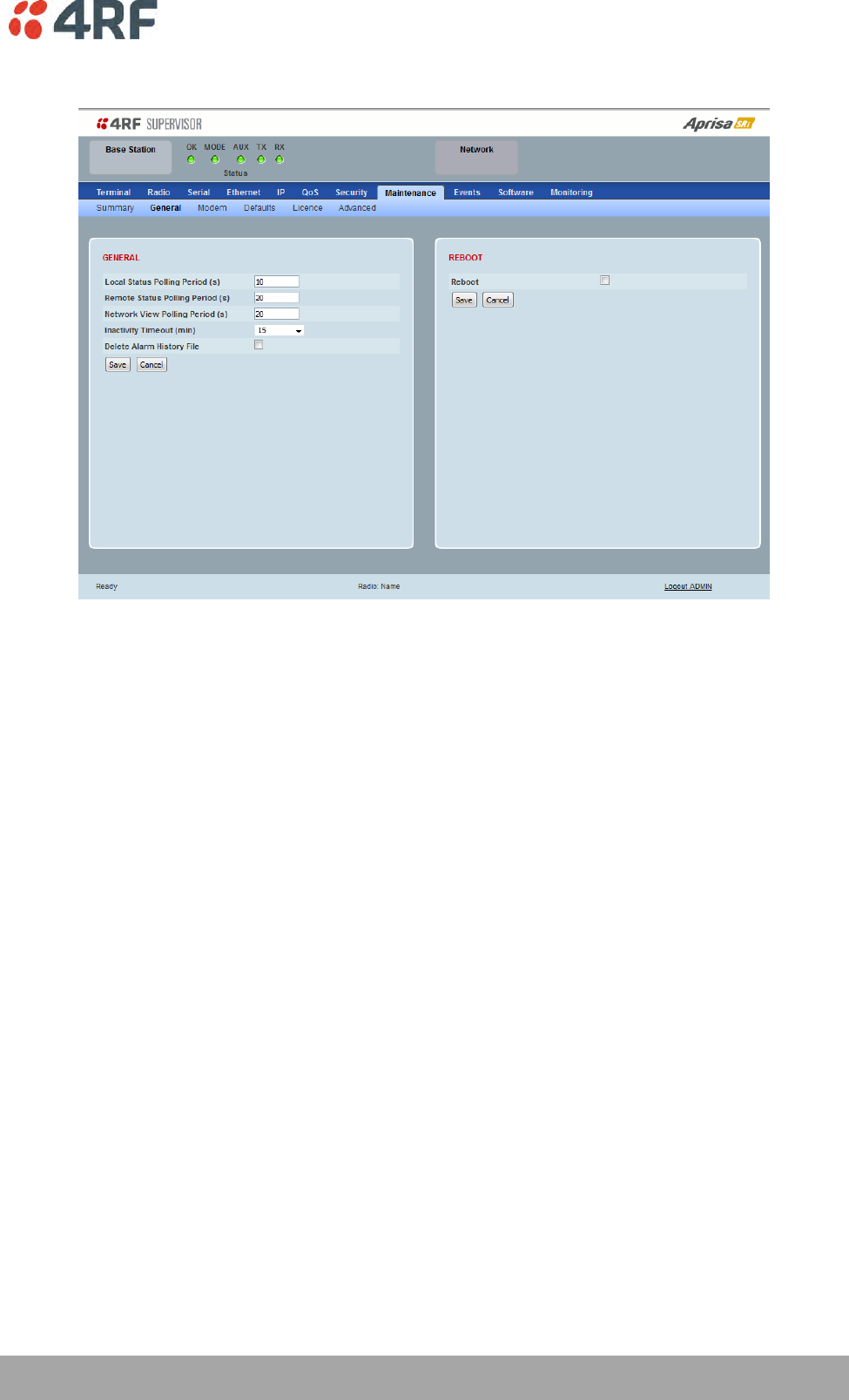
Managing the Radio | 185
Aprisa SRi User Manual 1.0.0
Maintenance > General
GENERAL
Local Status Polling Period (sec)
This parameter sets the rate at which SuperVisor refreshes the Local Radio alarm LED states and RSSI
value. The default setting is 10 seconds.
Network View Polling Period (sec)
This parameter sets the rate at which SuperVisor polls all remote radios for status and alarm reporting.
The default setting is 20 seconds.
Remote Status Polling Period (sec)
This parameter sets the rate at which SuperVisor refreshes the Remote Radio alarm LED states and RSSI
value. To avoid problems when managing Aprisa SRi Networks, ensure that the Remote Polling Period is set
to be longer than the Inband Management Timeout (set on page 82). The default setting is 20 seconds.
Inactivity Timeout (min)
This parameter sets the period of user inactivity before SuperVisor automatically logs out of the radio. The
default setting is 15 minutes.
Delete Alarm History file
This parameter when activated deletes the alarm history file stored in the radio.
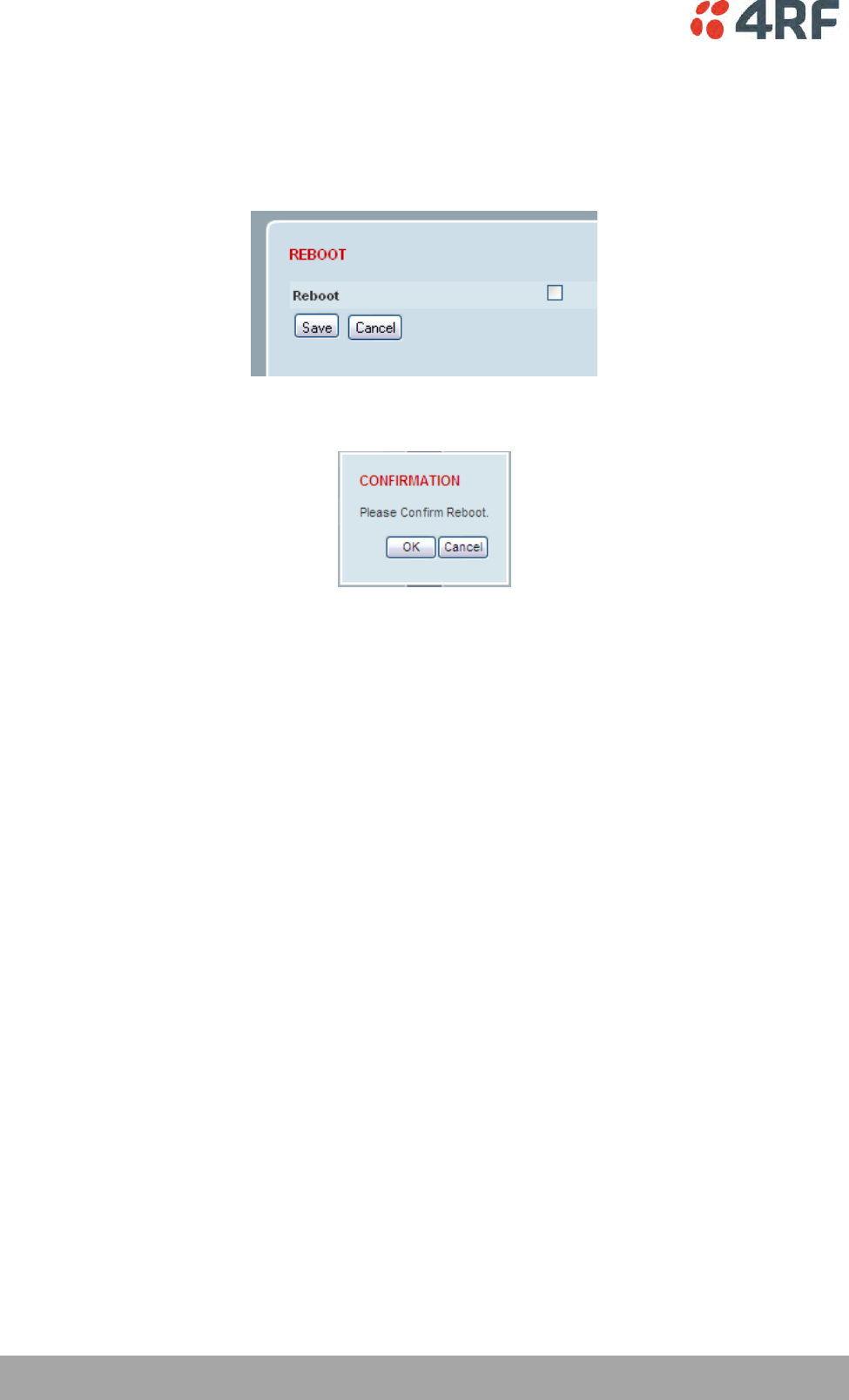
186 | Managing the Radio
Aprisa SRi User Manual 1.0.0
REBOOT
To reboot the radio:
1. Select Maintenance > General.
2. Tick the ‘Reboot’ checkbox.
3. Click ‘Save’ to apply the changes or ‘Cancel’ to restore the current value.
4. Click ‘OK’ to reboot the radio or ‘Cancel’ to abort.
All the radio LEDs will flash repeatedly for 1 second.
The radio will be operational again in about 10 seconds.
The OK, MODE, and AUX LEDs will light green and the TX and RX LEDs will be green (steady or flashing) if
the network is operating correctly.
5. Login to SuperVisor.
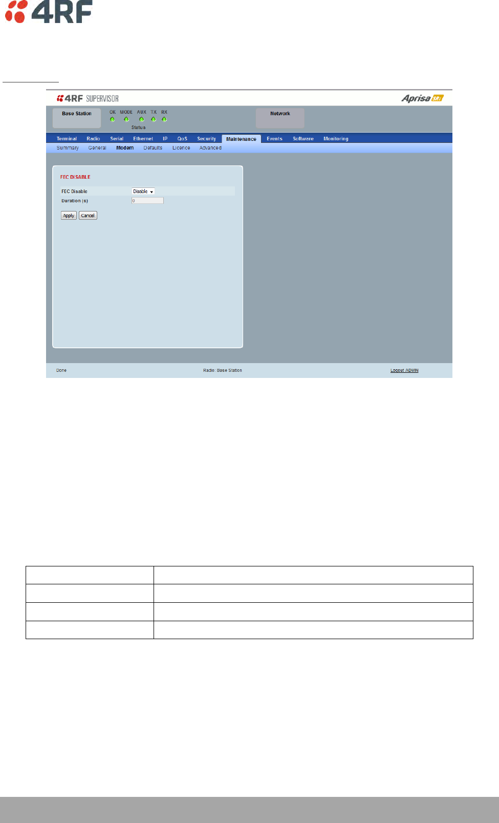
Managing the Radio | 187
Aprisa SRi User Manual 1.0.0
Maintenance > Modem
Base Station
FEC DISABLE
FEC Disable
This diagnostic function allows the user to temporarily disable forward error correction on the channel
when diagnosing problems on the link.
Therefore, enabling this diagnostic function would temporarily disable FEC on the channel and the
associated maintenance mode alarm would activate.
Note that the opposite is not true for this diagnostic function. In other words, this diagnostic function
does not provide the user with the option to temporarily enable forward error correction on the channel.
All diagnostic functions are not persistent and will be return to disabled states should the system restart.
Option
Function
Enable
Enables the FEC Disable diagnostic function
Disable
Disables the FEC Disable diagnostic function
Timer
Allows the FEC to be disabled but only for a predetermined period.
Duration (s)
This parameter defines the period required for disabling of the FEC. When this period elapses, the FEC is
enabled.
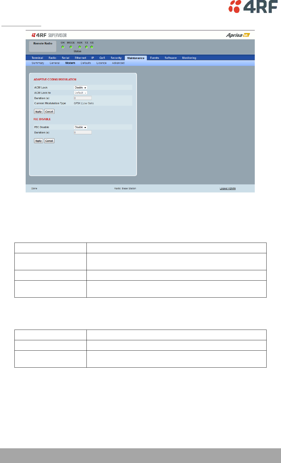
188 | Managing the Radio
Aprisa SRi User Manual 1.0.0
Remote Station
ADAPTIVE CODING AND MODULATION
ACM Lock
This parameter sets whether adaptive modulation can be locked or not.
Option
Function
Disable
Disables manual locking of the adaptive modulation i.e. allows for
automatic adaptive modulation.
Enable
Allows the adaptive modulation to be manually locked
Timer
Allows the adaptive modulation to be manually locked but only for
a predetermined period.
ACM Lock To
This parameter manually locks the adaptive modulation.
Option
Function
Default
Manually locks the adaptive modulation to the default
Current
Manually locks the adaptive modulation to the current modulation
at that time.
Duration (s)
This parameter defines the period required for manually locking the adaptive modulation. When this
period elapses, the adaptive modulation becomes automatic.

Managing the Radio | 189
Aprisa SRi User Manual 1.0.0
FEC DISABLE
FEC Disable
This diagnostic function allows the user to temporarily disable forward error correction on the channel
when diagnosing problems on the link.
Therefore, enabling this diagnostic function would temporarily disable FEC on the channel and the
associated maintenance mode alarm would activate.
Note that the opposite is not true for this diagnostic function. In other words, this diagnostic function
does not provide the user with the option to temporarily enable forward error correction on the channel.
All diagnostic functions are not persistent and will be return to disabled states should the system restart.
Option
Function
Enable
Enables the FEC Disable diagnostic function
Disable
Disables the FEC Disable diagnostic function
Timer
Allows the FEC to be disabled but only for a predetermined period.
Duration (s)
This parameter defines the period required for disabling of the FEC. When this period elapses, the FEC is
enabled.
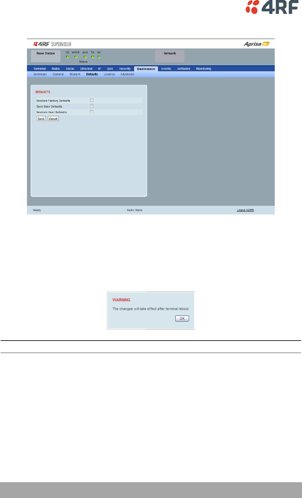
190 | Managing the Radio
Aprisa SRi User Manual 1.0.0
Maintenance > Defaults
DEFAULTS
The Maintenance Defaults page is only available for the local terminal.
Restore Factory Defaults
When activated, all radio parameters will be set to the factory default values. This includes resetting the
radio IP address to the default of 169.254.50.10.
Note: Take care using this command.
Save User Defaults
When activated, all current radio parameter settings will be saved to non-volatile memory within the
radio.
Restore User Defaults
When activated, all radio parameters will be set to the settings previously saved using ‘Save User
Defaults’.
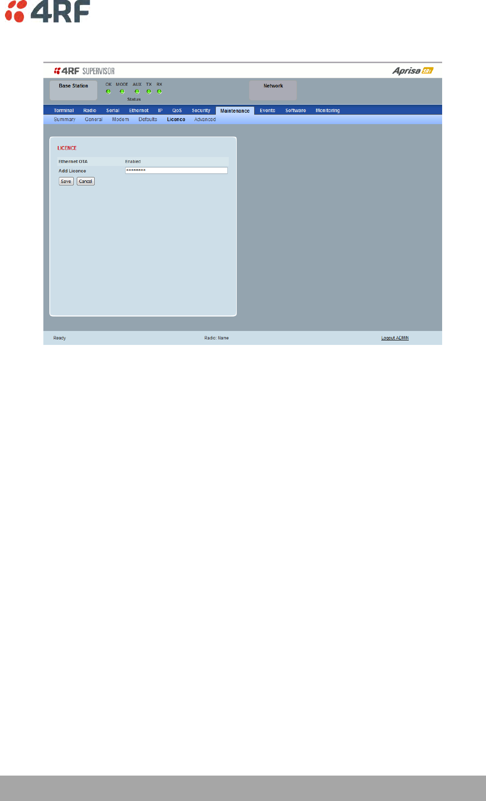
Managing the Radio | 191
Aprisa SRi User Manual 1.0.0
Maintenance > Licence
LICENCE
In this software version, Remote Management, Ethernet Traffic and SNMP management are enabled by
default.
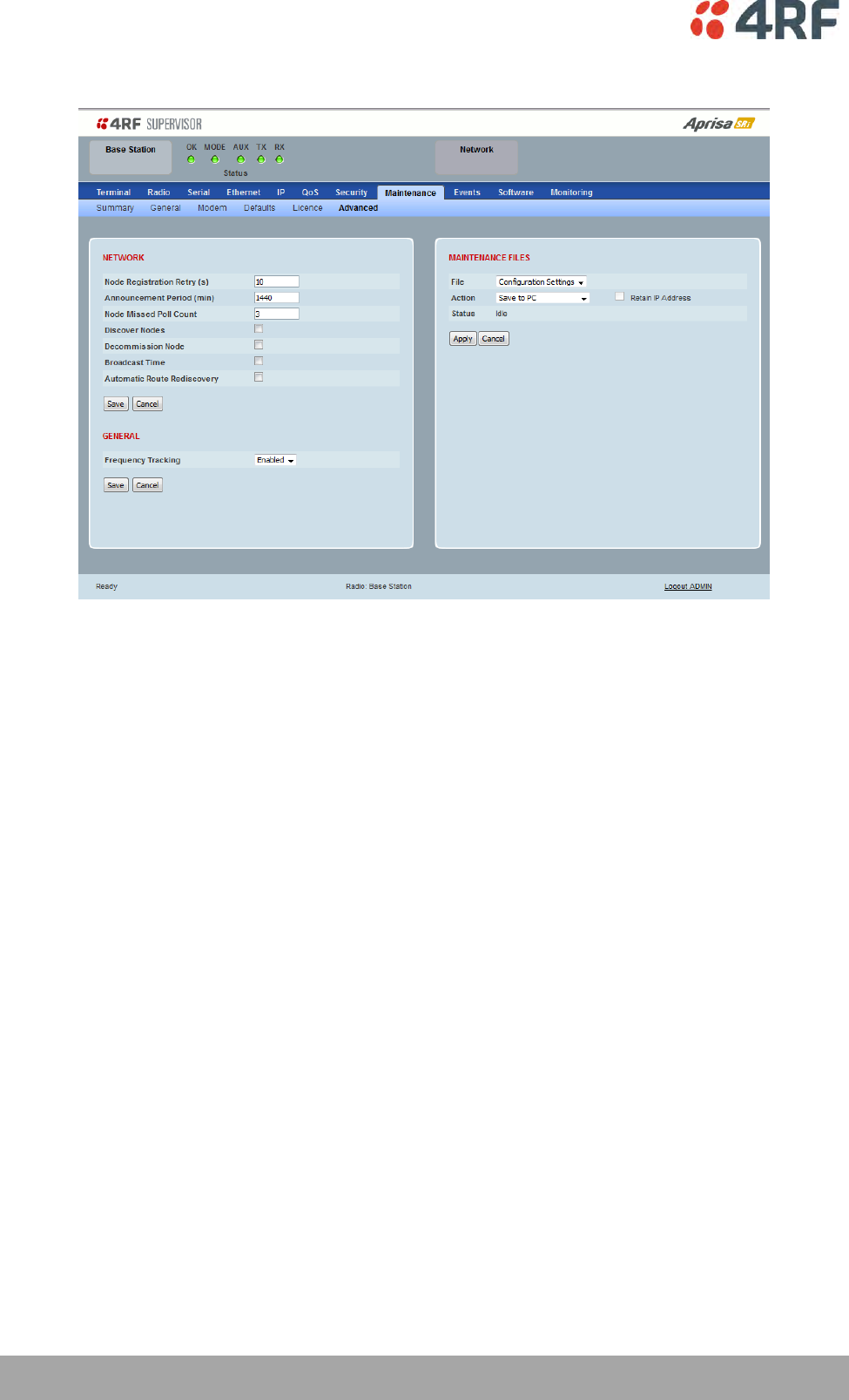
192 | Managing the Radio
Aprisa SRi User Manual 1.0.0
Maintenance > Advanced
NETWORK
Node Registration Retry (sec)
This parameter sets the base station poll time at startup or the remote station time between retries until
registered. The default setting is 10 seconds.
Base Station Announcement Period (min)
This parameter sets the period between base station polls post startup. The default setting is 1440
minutes (24 hours).
When a new base station powers on, it announces its presence and each remote that receives the
announcement message will be advised that a new base station is present and that they should re-register.
This allows the new base station to populate its Network Table, with knowledge of the nodes in the
network.
If, during this initial period, there is some temporary path disturbance to one or more remotes, they may
miss the initial announcement messages and be left unaware of the base station change. For this reason,
the base station must periodically send out announcement messages to pick up any stray nodes and the
period of these messages is the base station Announcement Period.
Setting this parameter to 0 will stop periodic announcement messages being transmitted.
If a critical parameter is changed in the base station, such as IP address, then the change is distributed to
the network using base station announcement message. Note that in this case, an announcement is sent
immediately independent of the Announcement Period setting.

Managing the Radio | 193
Aprisa SRi User Manual 1.0.0
Node Missed Poll Count
This parameter sets the number of times the base station attempts to poll the network at startup or if a
duplicate IP is detected when a remote station is replaced. The default setting is 3.
Discover Nodes
This parameter when activated triggers the base station to poll the network with Node Missed Poll Count
and Node Registration Retry values.
Decommission Node(s)
This parameter when activated resets the network registrations to remove the entire network from
service.
Note: Take care using this option.
Broadcast Time
This parameter when activated sends the base station Date / Time setting to all the remote stations in the
network and sets their Date / Time. This option applies to the base station only.
Automatic Route Rediscovery
This parameter enables the radio to transmit route discovery messages when packets are unacknowledged.
When enabled, unacknowledged unicast packets are converted into uni-broadcast messages and sent
through the network. All nodes see the message and populate their routing tables accordingly.
When the destination node is reached, it sends a route response message via the shortest path. The
intermediate nodes see this message and populate their routing tables in the reverse direction, thus re-
establishing the route.
The default setting is disabled.
Delete Received Channel List – Remote Radios Only
This parameter deletes the existing zone channel list and uses the configured zone channel allocation
setup with Zone Setup on page 101 until it re-registers with the base station and receives the new
distributed zone channel list.
GENERAL
Frequency Tracking
Frequency Tracking enables the receiver to track any frequency drift in the transmitter to maintain
optimum SNR and radio link performance over the full temperature range.
When enabled, remote stations adjust their receive frequency to the frequency of the incoming packet
rate and the base station notifies remote stations if their transmit frequency requires adjustment.
The default setting is Enabled.
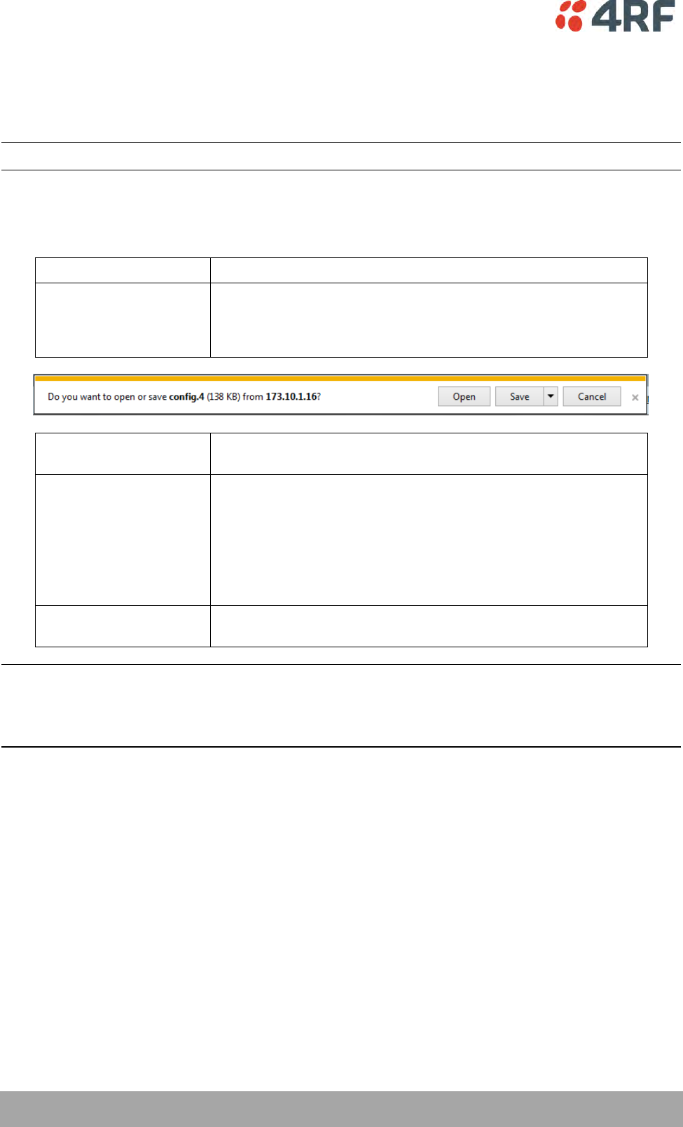
194 | Managing the Radio
Aprisa SRi User Manual 1.0.0
MAINTENANCE FILES
There are three maintenance file types which can saved / restored to / from PC or USB flash drive:
Note: Some brands of USB flash drives may not work with 4RF radios.
File - Configuration Settings
Action
Action
Option
Save to PC
This saves the file with a filename of ‘Config.4’ to a binary
encrypted file. This can then be saved from the Browser popup
(example is Windows Internet Explorer 11). The file should be
renamed to be able to identify the radio it was saved from.
Save to Radio USB
This saves the file with a filename of ‘asrcfg_1.0.0’ to a binary
encrypted file on the radio USB flash drive root directory.
Restore from PC
This restores all user configuration settings from a binary
encrypted file on a PC directory to the radio.
A reboot warning message will warn of a pending reboot after the
PC file is selected. Clicking OK will open a browser file selection
window to select the file.
Note: If you are using Explorer, it must be IE10 or above for this
feature to work correctly.
Restore from Radio USB
This restores all user configuration settings from a binary
encrypted file on the USB root directory to the radio.
Note: ‘Payload Encryption Key’ and ‘Key Encryption Key’ parameters (see ‘Security > Setup’) are not
saved to the configuration file. When a ‘Restore from PC’ or ‘Restore from Radio USB’ is used, these
parameters will retain their existing values so are not changed by the operation of restoring the
configuration file.
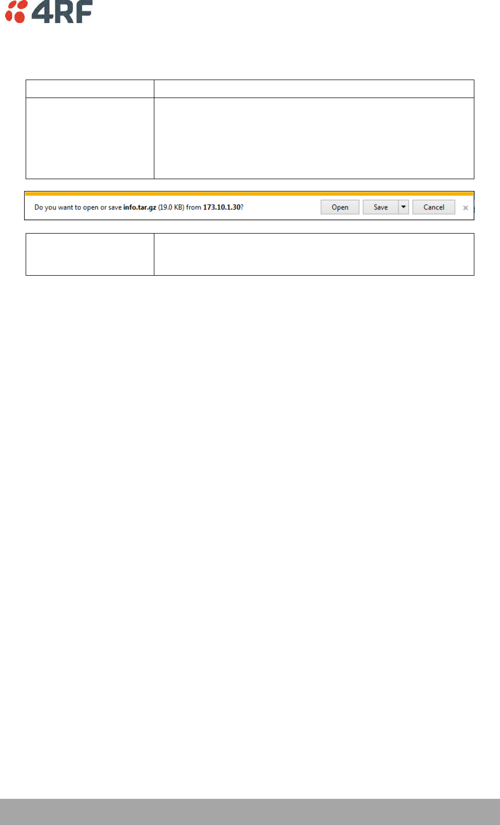
Managing the Radio | 195
Aprisa SRi User Manual 1.0.0
File - Event History Log
Action
Action
Option
Save to PC
This saves the file with a filename of ‘Info.tar.gz’ to a binary
encrypted file. This can then be saved from the Browser popup
(example is Windows Internet Explorer 11). The file should be
renamed to be able to identify the radio it was saved from.
The ‘gz’ file is normally for sending back to 4RF Limited for
analysis but can be opened with WinRar.
Save to Radio USB
This saves the file with a filename of e.g.
‘alarm_173.10.1.30_2014-11-10,15.54.14.txt’ to a text file on the
radio USB flash drive root directory.

196 | Managing the Radio
Aprisa SRi User Manual 1.0.0
File - Configuration Script
Action
Action
Option
Load and Execute
This loads and executes configuration script files.
There are sample configuration script files on the product CD in a
directory called ‘Master Configuration’.
The purpose of these files is to use as templates to create your
own configuration scripts.
Note: Be careful using this feature as incompatible configurations
will change the radios settings and break radio connectivity.
Note: Activating this function will over-write all existing configuration settings in the radio (except for the
non-saved settings e.g. security passwords, licence keys etc) without any verification of the command
setting in the radio. Precautions should be taken to prevent radio outages with incorrect radio
configurations. The following process steps are recommended:
a. Save the current radio configuration to a PC or USB before uploading the new configuration script
file
b. Upload the new configuration script file to the radio
c. If for some reason the radio doesn’t work as expected, the saved configuration file can be
uploaded to the radio (roll back to previous configuration).
Retain IP Address
This parameter when enabled ensures that the radio IP address is not changed when the radio
configuration settings are restored from a configuration file with a different IP radio address. It prevents
the radio losing connectivity when the configuration settings are restored from a configuration file.
Revert Config if Connection Lost
When the Maintenance Files feature is used on remote radios from the base station, this parameter allows
the configurations to be restored to the previous configuration if the connection is lost.
This must be set before executing the Configuration Settings / Configuration Script restore functions.
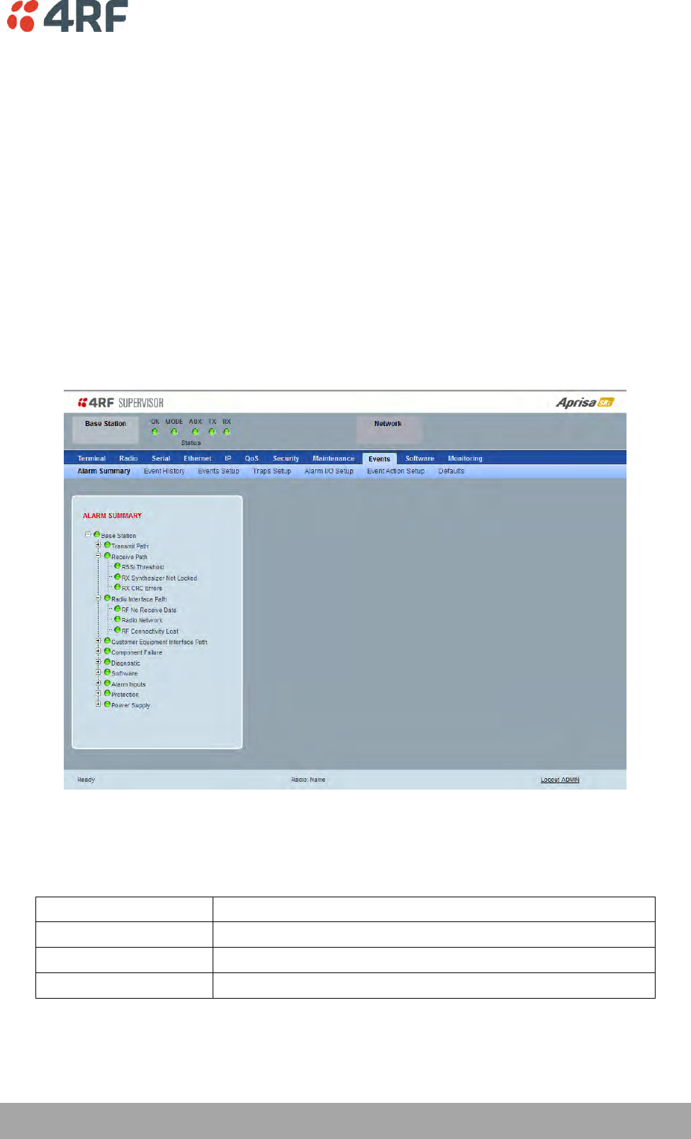
Managing the Radio | 197
Aprisa SRi User Manual 1.0.0
Events
The Events menu contains the setup and management of the alarms, alarm events and traps.
Events > Alarm Summary
There are two types of events that can be generated on the Aprisa SRi radio. These are:
1. Alarm Events
Alarm Events are generated to indicate a problem on the radio.
2. Informational Events
Informational Events are generated to provide information on key activities that are occurring on the
radio. These events do not indicate an alarm on the radio and are used to provide information only.
See ‘Alarm Types and Sources’ on page 273 for a complete list of events.
ALARM SUMMARY
The Alarm Summary is a display tree that displays the current states of all radio alarms. The alarm states
refresh automatically every 12 seconds.
LED Colour
Severity
Green
No alarm
Orange
Warning alarm
Red
Critical, major or minor alarm
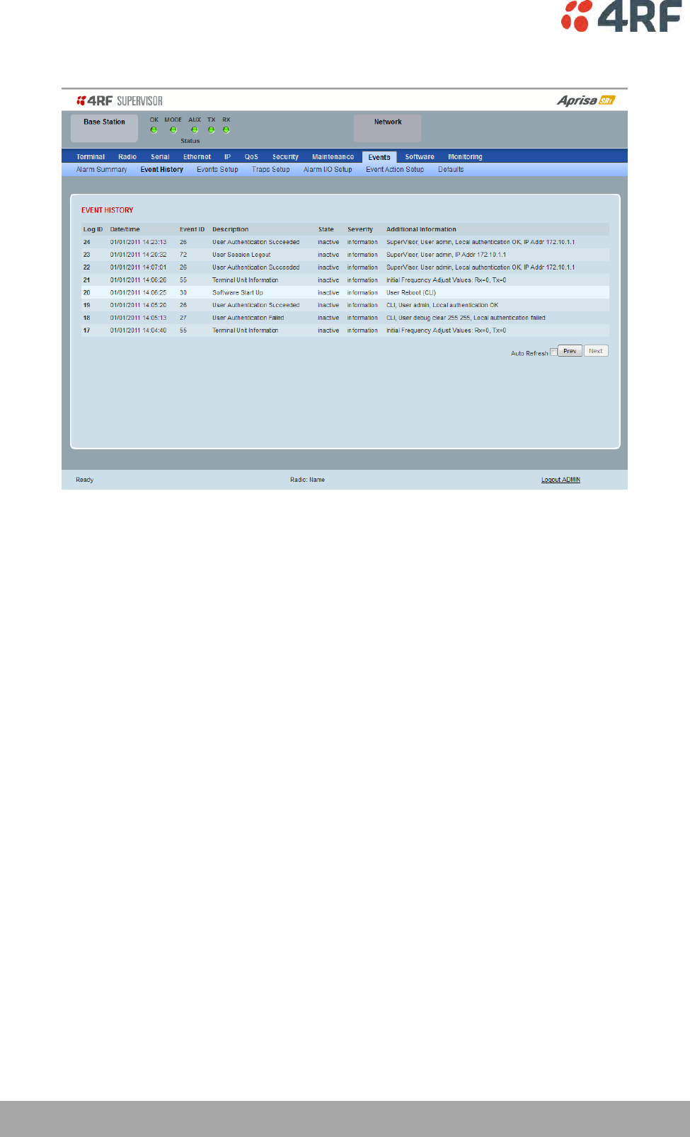
198 | Managing the Radio
Aprisa SRi User Manual 1.0.0
Events > Event History
EVENT HISTORY
The last 1500 events are stored in the radio. The complete event history list can be downloaded to a USB
flash drive (see ‘File - Event History Log’ on page 195).
The Event History can display the last 50 events stored in the radio in blocks of 8 events.
The Next button will display the next page of 8 events and the Prev button will display the previous page
of 8 events. Using these buttons will disable Auto Refresh to prevent data refresh and page navigation
contention.
The last 50 events stored in the radio are also accessible via an SNMP command.
Auto Refresh
The Event History page selected will refresh automatically every 12 seconds if the Auto Refresh is ticked.
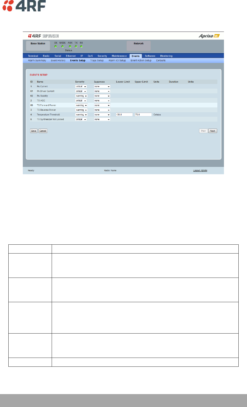
Managing the Radio | 199
Aprisa SRi User Manual 1.0.0
Events > Events Setup
EVENTS SETUP
Alarm event parameters can be configured for all alarm events (see ‘Alarm Events’ on page 274).
All active alarms for configured alarm events will be displayed on the Monitoring pages (see ‘Monitoring’
on page 227).
Severity
The Severity parameter sets the alarm severity.
Severity
Function
Critical
The Critical severity level indicates that a service affecting condition has occurred and
an immediate corrective action is required. Such a severity can be reported, for
example, when a managed object becomes totally out of service and its capability must
be restored.
Major
The Major severity level indicates that a service affecting condition has developed and
an urgent corrective action is required. Such a severity can be reported, for example,
when there is a severe degradation in the capability of the managed object and its full
capability must be restored.
Minor
The Minor severity level indicates the existence of a non-service affecting fault
condition and that corrective action should be taken in order to prevent a more serious
(for example, service affecting) fault.
Such a severity can be reported, for example, when the detected alarm condition is not
currently degrading the capacity of the managed object.
Warning
The Warning severity level indicates the detection of a potential or impending service
affecting fault, before any significant effects have been felt. Action should be taken to
further diagnose (if necessary) and correct the problem in order to prevent it from
becoming a more serious service affecting fault.
Information
No problem indicated – purely information

200 | Managing the Radio
Aprisa SRi User Manual 1.0.0
Suppress
This parameter determines if the action taken by an alarm.
Option
Function
None
Alarm triggers an event trap and is logged in the radio
Traps
Alarm is logged in the radio but does not trigger an event trap
Traps and Log
Alarm neither triggers an event trap nor is logged in the radio
Lower Limit / Upper Limit
Threshold alarm events have lower and upper limit settings. The alarm is activated if the current reading
is outside the limits.
Example: 9 RX CRC Errors
The Upper Limit is set to 0.7 and the Duration is set to 5 seconds.
If in any 5 second period, the total number of errored packets divided by the total number of received
packets exceeds 0.7, the alarm will activate.
Units (1)
The Units parameter shows the unit for the Lower Limit and Upper Limit parameters.
Duration
This parameter determines the period to wait before an alarm is raised if no data is received.
Units (2)
This parameter shows the unit for the Duration parameters.
The Next button will display the next page of 8 alarm events and the Prev button will display the previous
page of 8 alarm events.
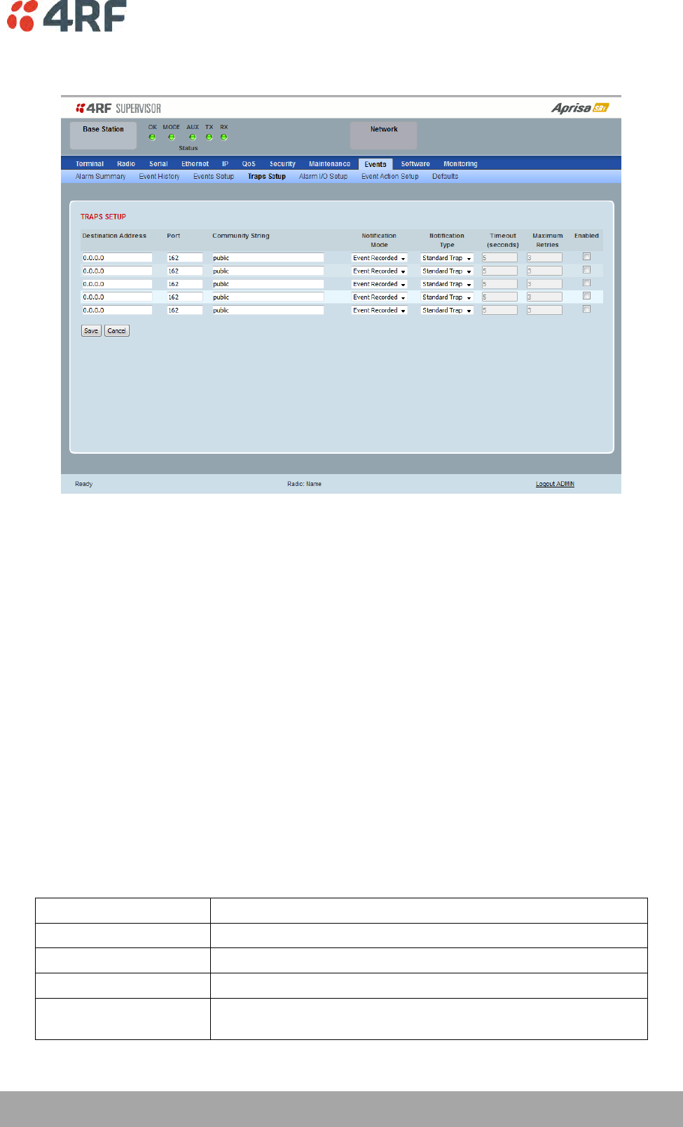
Managing the Radio | 201
Aprisa SRi User Manual 1.0.0
Events > Traps Setup
TRAPS SETUP
All events can generate SNMP traps. The types of traps that are supported are defined in the ‘Notification
Mode’.
Destination Address
This parameter sets the IP address of the server running the SNMP manager.
Port
This parameter sets the port number the server running the SNMP manager.
Community String
This parameter sets the community string which is sent with the IP address for security. The default
community string is ‘public’.
Notification Mode
This parameter sets when an event related trap is sent:
Option
Function
None
No event related traps are sent.
Event Recorded
When an event is recorded in the event history log, a trap is sent.
Event Updated
When an event is updated in the event history log, a trap is sent.
All Events
When an event is recorded or updated in the event history log, a
trap is sent.

202 | Managing the Radio
Aprisa SRi User Manual 1.0.0
Notification Type
This parameter sets the type of event notification:
Option
Function
Standard Trap
Provides a standard SNMP trap event
Inform Request
Provides a SNMP v2 Inform Request trap event including trap retry
and acknowledgement
Notification Type set to Inform Request:
Timeout (second)
This parameter sets the time interval to wait for an acknowledgement before sending another retry.
Maximum Retries
This parameter sets the maximum number of retries to send the event without acknowledgement before it
gives up.
Enabled
This parameter determines if the entry is used.
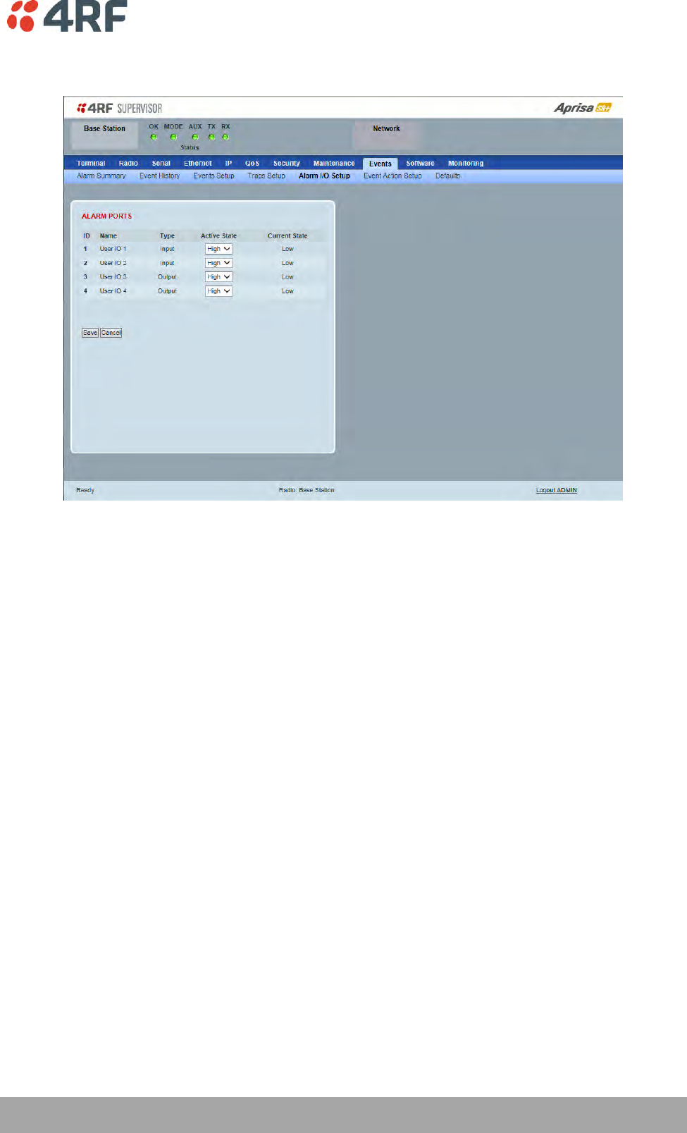
Managing the Radio | 203
Aprisa SRi User Manual 1.0.0
Events > Alarm I/O Setup
ALARM PORTS
This page provides control of the two hardware alarm inputs and two hardware alarm outputs provided on
the alarm connector.
The alarm inputs are used to transport alarms to the other radios in the network. The alarm outputs are
used to receive alarms from other radios in the network.
Name
The alarm IO number.
Type
The Type shows if the alarm is an input or output.

204 | Managing the Radio
Aprisa SRi User Manual 1.0.0
Active State
The Active State parameter sets the alarm state when the alarm is active.
Alarm Input
Option
Function
Low
The alarm is active low i.e. a ground contact on the port will cause
an active alarm state
High
The alarm is active high i.e. an open contact on the port will cause
an active alarm state
Alarm Output
Option
Function
Low
The alarm is active low i.e. the active alarm state will generate a
ground contact output
High
The alarm is active high i.e. the active alarm state will generate a
open contact output
Current State
The Current State shows the current state of the alarm.
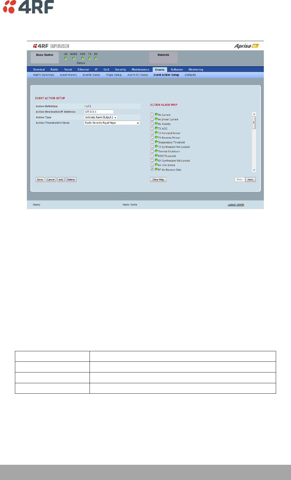
Managing the Radio | 205
Aprisa SRi User Manual 1.0.0
Events > Event Action Setup
EVENT ACTION SETUP
This page provides control of the mapping of events to specific actions. Specific alarm events can setup to
trigger outputs.
Action Definition
This parameter shows the number of the event action setup and the maximum number of setups stored.
Action Destination IP Address
This parameter sets the IP address of the radio that will output the action type.
Action Type
This parameter sets the action type that will be activated on the radio.
Option
Function
None
This action setup does not activate any alarm output
Activate Alarm Output 1
This action setup activates alarm output 1
Activate Alarm Output 2
This action setup activates alarm output 2

206 | Managing the Radio
Aprisa SRi User Manual 1.0.0
Action Threshold Criteria
This parameter sets the radio event that will trigger the action output.
Option
Function
None
No action output.
Radio Severity Equal Critical
Activates the action output when a radio alarm is critical
alarm
Radio Severity Equal Major
Activates the action output when a radio alarm is a major
alarm
Radio Severity Equal Minor
Activates the action output when a radio alarm is minor
alarm
Radio Severity Equal Warning
Activates the action output when a radio alarm is a
warning alarm
Radio Severity Equal Cleared
Activates the action output when a radio alarm is cleared
Radio Severity Equal or Worse than
Major
Activates the action output when a radio alarm is a major
alarm or a critical alarm
Radio Severity Equal or Worse than
Minor
Activates the action output when a radio alarm is a minor
alarm, a major alarm or a critical alarm
Radio Severity Equal or Worse than
Warning
Activates the action output when a radio alarm is a
warning, a major alarm, a minor alarm or a critical alarm
Controls
The Save button saves the current event action setup.
The Cancel button cancels the new event action setup.
The Add button adds a new event action setup.
The Delete button deletes the current event action setup.
The Clear Map button clears all alarm selections on the current setup.
To add an event action setup:
1. Click on the Add button.
2. Enter the Action Destination IP Address. This is the IP address of the radio that will output the action
type.
3. Select the Action Type from the list.
4. Select the Action Threshold Criteria from the list.
5. Tick the alarms required for the event action setup from the Action Alarm Map. You can clear all
alarm selections with the Clear Map button.
6. Click on Save.
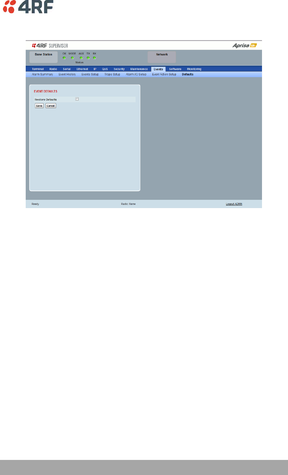

208 | Managing the Radio
Aprisa SRi User Manual 1.0.0
Software
The Software menu contains the setup and management of the system software including network
software distribution and activation. The distribution of the system software to the remote radios is
encrypted by the AES session key over-the-air.
Single Radio Software Upgrade
The radio software can be upgraded on a single Aprisa SRi radio (see ‘Single Radio Software Upgrade’ on
page 268). This process would only be used if the radio was a replacement or a new station in an existing
network.
Network Software Upgrade
The radio software can be upgraded on an entire Aprisa SRi radio network remotely over the radio link
(see ‘Network Software Upgrade’ on page 266). This process involves following steps:
1. Transfer the new software to base station with ‘Software > File Transfer’
2. Distribute the new software to all remote stations with ‘Software > Remote Distribution’
3. Activate of the new software on remote stations with ‘Software > Remote Activation’.
4. Finally, activate the new software on the base station radio with ‘Software > Manager’. Note:
activating the software will reboot the radio.
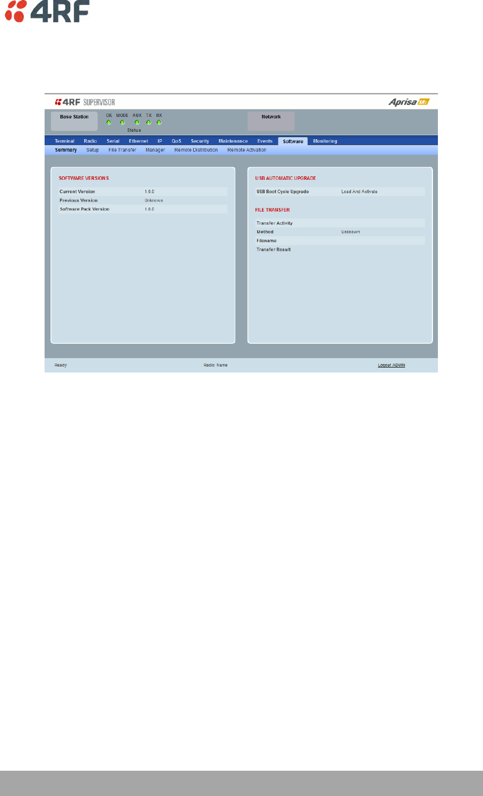
Managing the Radio | 209
Aprisa SRi User Manual 1.0.0
Software > Summary
This page provides a summary of the software versions installed on the radio, the setup options and the
status of the File Transfer.
SOFTWARE VERSIONS
Current Version
This parameter displays the software version running on the radio.
Previous Version
This parameter displays the software version that was running on the radio prior to the current software
being activated.
Software Pack Version
On the base station, this parameter displays the software version available for distribution to all radios in
the network.
On the all stations, this parameter displays the software version ready for activation.
USB AUTOMATIC UPGRADE
USB Boot Upgrade
This parameter shows the type of USB Boot upgrade defined in ‘Software Setup > USB Boot Upgrade’ on
page 211.

210 | Managing the Radio
Aprisa SRi User Manual 1.0.0
FILE TRANSFER
Transfer Activity
This parameter shows the status of the transfer, ‘Idle’, ‘In Progress’ or ‘Completed’.
Method
This parameter shows the file transfer method. When the software distribution is in progress, this
parameter will change to ‘Over the Air’ (from xx.xx.xx.xx) to show that the interface is busy and the
transfer is in progress.
File
This parameter shows the software file source.
Transfer Result
This parameter shows the progress of the transfer.
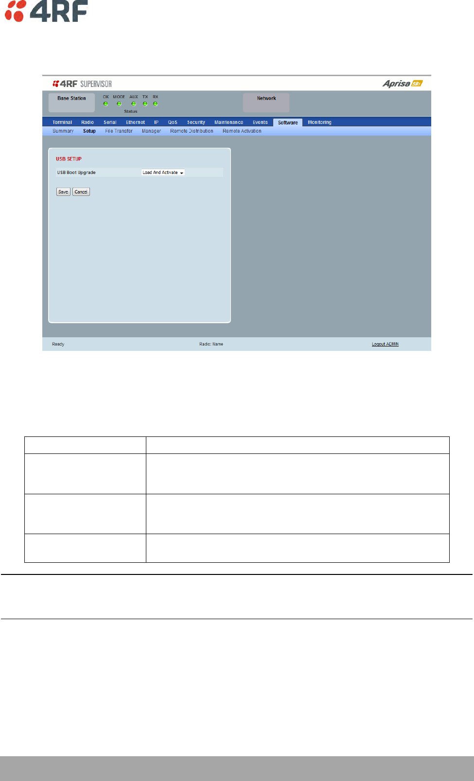
Managing the Radio | 211
Aprisa SRi User Manual 1.0.0
Software > Setup
This page provides the setup of the USB flash drive containing a Software Pack.
USB SETUP
USB Boot Upgrade
This parameter determines the action taken when the radio power cycles and finds a USB flash drive in the
Host port. The default setting is ‘Load and Activate’.
Option
Function
Load and Activate
New software will be uploaded from a USB flash drive in to the
Aprisa SRi when the radio is power cycled and activated
automatically.
Load Only
New software will be uploaded from a USB flash drive in to the
Aprisa SRi when the radio is power cycled. The software will need
to be manually activated (see ‘Software > Manager’ on page 216).
Disabled
Software will not be uploaded from a USB flash drive into the
Aprisa SRi when the radio is power cycled.
Note: This parameter must be set to ‘Disabled’ if the ‘File Transfer and Activate’ method of upgrade is
used. This ‘Disabled’ setting prevents the radio from attempting another software upload when the radio
boots (which it does automatically after activation).
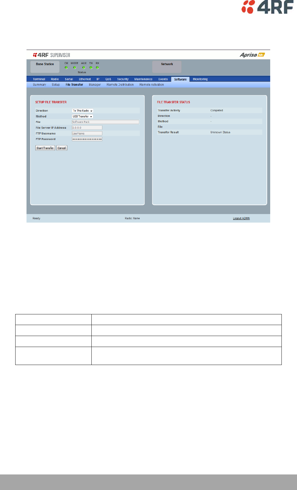
212 | Managing the Radio
Aprisa SRi User Manual 1.0.0
Software > File Transfer
This page provides the mechanism to transfer new software from a file source into the radio.
SETUP FILE TRANSFER
Direction
This parameter sets the direction of file transfer. In this software version, the only choice is ‘To the
Radio’.
Method
This parameter sets the method of file transfer.
Option
Function
USB Transfer
Transfers the software from the USB flash drive to the radio.
FTP
Transfers the software from an FTP server to the radio.
HTTP / HTTPS
Transfers the software directly from a PC software pack file to the
radio.
File
This parameter shows the software file source.
FTP Username
This parameter sets the Username to access the FTP server.
FTP Password
This parameter sets the Password to access the FTP server.
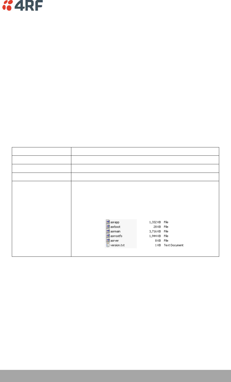
Managing the Radio | 213
Aprisa SRi User Manual 1.0.0
FILE TRANSFER STATUS
Transfer Activity
This parameter shows the status of the transfer, ‘Idle’, ‘In Progress’ or ‘Completed’.
Direction
This parameter shows the direction of file transfer. In this software version, the only choice is ‘To The
Radio’.
Method
This parameter shows the file transfer method.
File
This parameter shows the software file source.
Transfer Result
This parameter shows the progress of the transfer:
Transfer Result
Function
Starting Transfer
The transfer has started but no data has transferred.
In Progress (x %)
The transfer has started and has transferred x % of the data.
Successful
The transfer has finished successfully.
File Error
The transfer has failed.
Possible causes of failure are:
Is the source file available e.g. USB flash drive plugged in
Does the file source contain the Aprisa SRi software release
files;
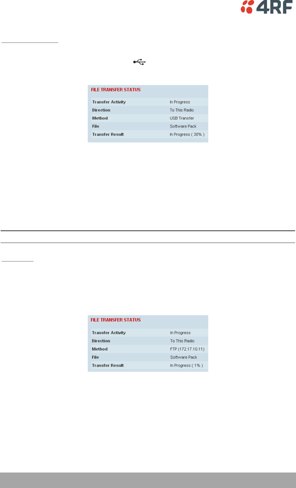
214 | Managing the Radio
Aprisa SRi User Manual 1.0.0
To transfer software into the Aprisa SRi radio:
USB Transfer Method
1. Unzip the software release files in to the root directory of a USB flash drive.
2. Insert the USB flash drive into the host port .
3. Click on ‘Start Transfer’.
4. When the transfer is completed, remove the USB flash drive from the host port. If the SuperVisor ‘USB
Boot Upgrade’ setting is set to ‘Disabled’ (see ‘USB Boot Upgrade’ on page 211), the USB flash drive
doesn’t need to be removed as the radio won’t try to load from it.
Go to Supervisor > Software > Manager and activate the Software Pack (see ‘Software > Manager’ on page
216). The radio will reboot automatically.
If the file transfer fails, check the Event History page (see ‘Events > Event History’ on page 198) for more
details of the transfer.
Note: Some brands of USB flash drives may not work with 4RF radios.
FTP Method
1. Unzip the software release files in to a temporary directory.
2. Open the FTP server and point it to the temporary directory.
3. Enter the FTP server IP address, Username and password into SuperVisor.
4. Click on ‘Start Transfer’.
Go to Supervisor > Software > Manager and activate the Software Pack (see ‘Software > Manager’ on page
216). The radio will reboot automatically.
If the file transfer fails, check the Event History page (see ‘Events > Event History’ on page 198) for more
details of the transfer.

Managing the Radio | 215
Aprisa SRi User Manual 1.0.0
HTTP / HTTPS Method
1. Unzip the software release files in to a temporary directory.
2. Click on ‘Start Transfer’.
3. Browse to the *.swpack file in the temporary directory and open the file.
Go to Supervisor > Software > Manager and activate the Software Pack (see ‘Software > Manager’ on page
216). The radio will reboot automatically.
If the file transfer fails, check the Event History page (see ‘Events > Event History’ on page 198) for more
details of the transfer.
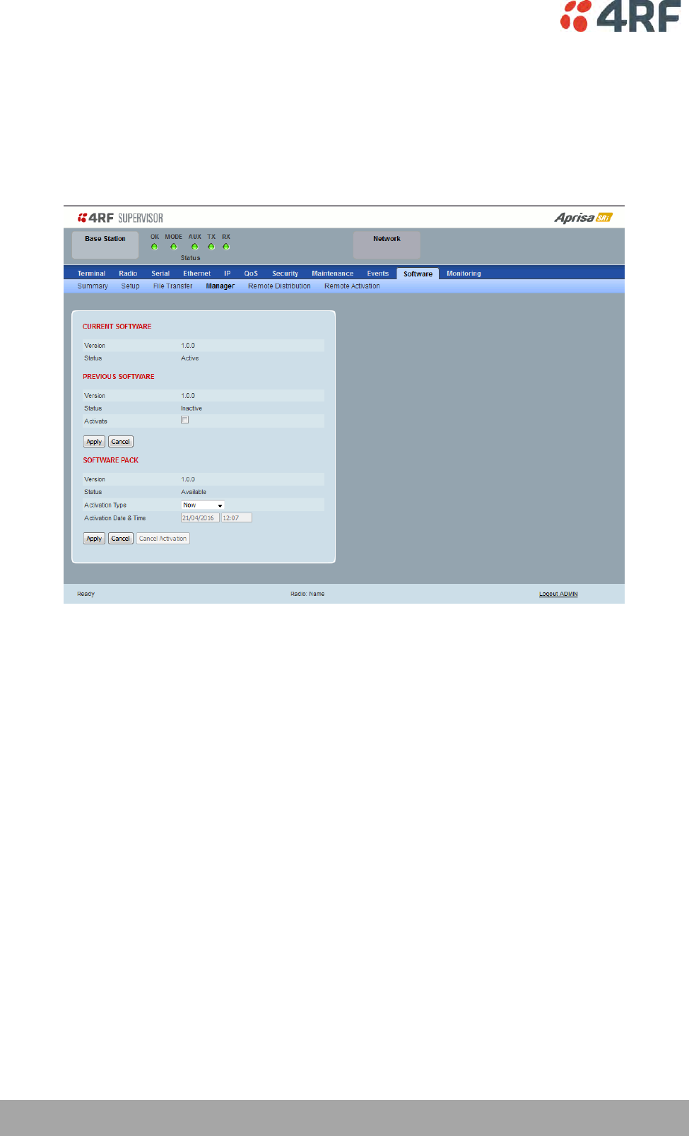
216 | Managing the Radio
Aprisa SRi User Manual 1.0.0
Software > Manager
This page summarises and manages the software versions available in the radio.
The manager is predominantly used to activate new software on single radios. Network activation is
performed with ‘Software > Remote Activation’.
Both the previous software (if available) and Software Pack versions can be activated on the radio from
this page.
CURRENT SOFTWARE
Version
This parameter displays the software version running on the radio.
Status
This parameter displays the status of the software version running on the radio (always active).
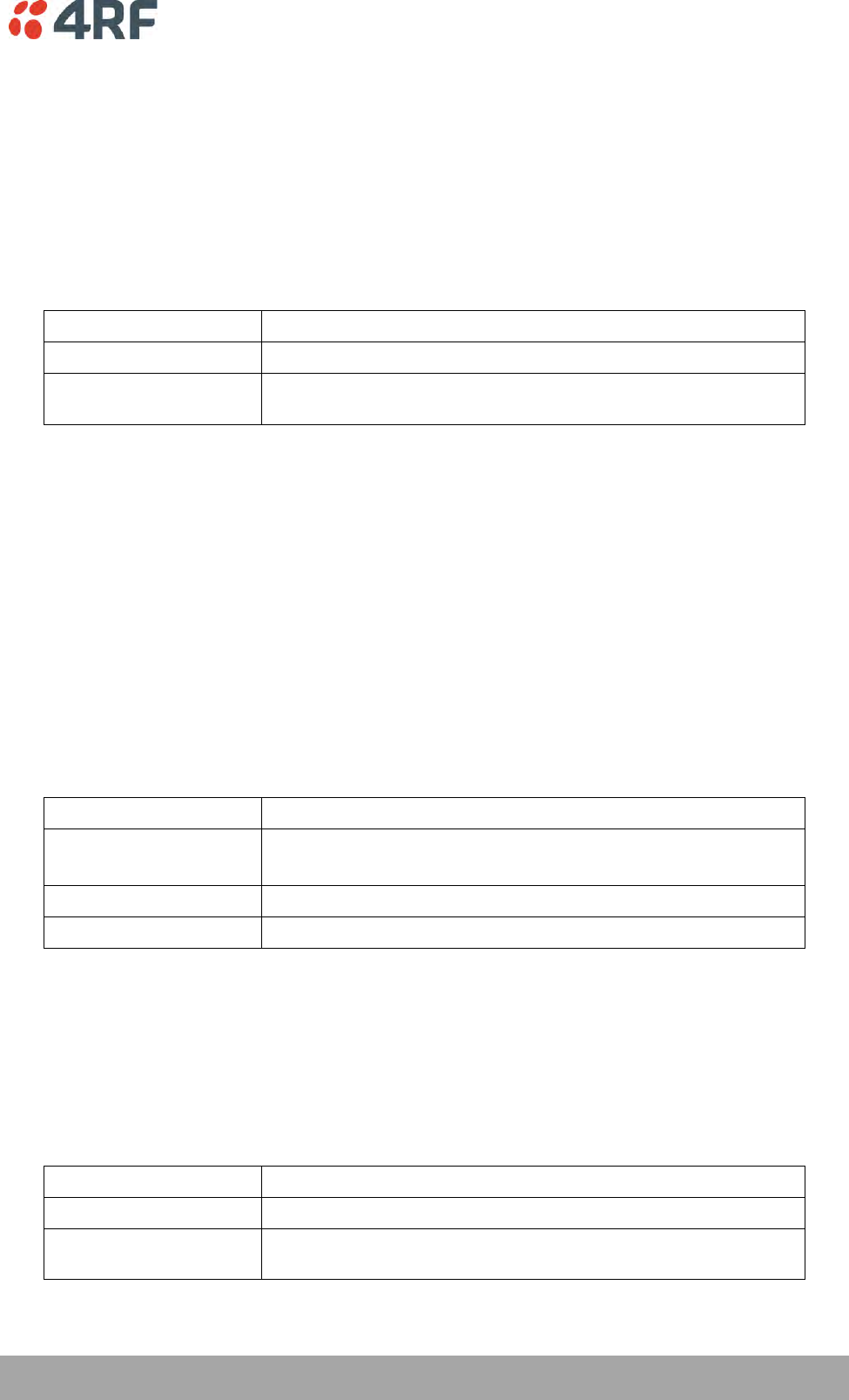
Managing the Radio | 217
Aprisa SRi User Manual 1.0.0
PREVIOUS SOFTWARE
Version
This parameter displays the software version that was running on the radio prior to the current software
being activated.
Status
This parameter displays the status of the software version that was running on the radio prior to the
current software being activated.
Option
Function
Active
The software is operating the radio.
Inactive
The software is not operating the radio but could be re-activated if
required.
Activate
This parameter activates the previous software version (restores to previous version).
The Aprisa SRi will automatically reboot after activation.
SOFTWARE PACK
Version
This parameter displays the software pack version available for distribution on base station and activate
on all stations.
Status
This parameter displays the status of the software pack version.
Option
Function
Available
On the base station, the software pack is available for distribution.
On all stations, the software pack is available for activation.
Activating
The software pack is activating in the radio.
Unavailable
There is no software pack loaded into the radio.
Activate
This parameter activates the software pack.
The Aprisa SRi will automatically reboot after activation.
Activation Type
This parameter sets when the software pack activation will occur.
Option
Function
Now
Activates the software pack now.
Date & Time
Activates the software pack at the Date & Time set in the following
parameter.
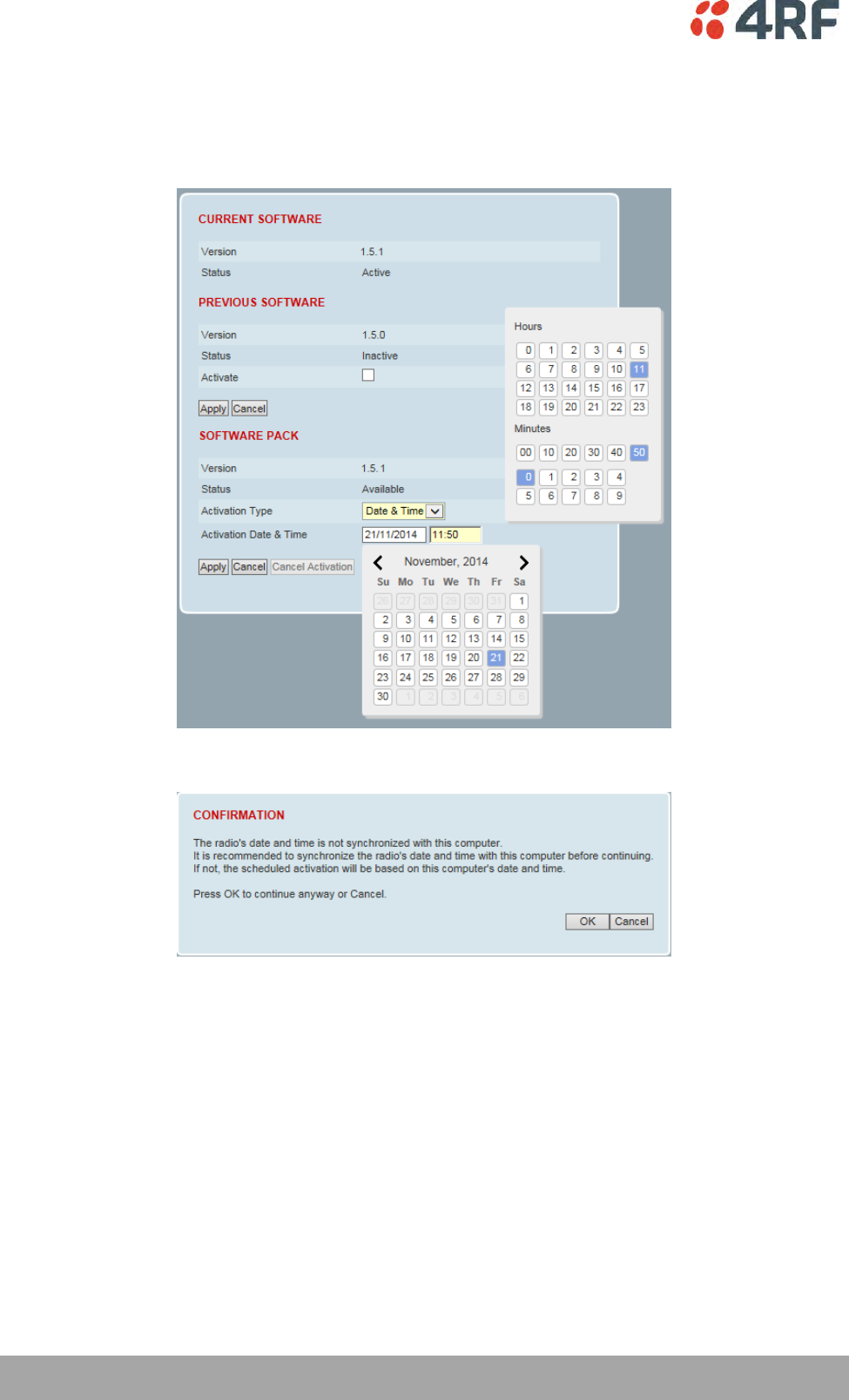
218 | Managing the Radio
Aprisa SRi User Manual 1.0.0
Activation Date & Time
This parameter sets the Date & Time when the software pack activation will occur.
This setting can be any future date and 24 hour time.
If the network base station radio date / time is not synchronized, you will get the following popup:
You can manually enter the base station radio date / time or use the Date And Time Synchronization from
a SNTP server feature (see ‘Terminal > Date / Time’ on page 84).

Managing the Radio | 219
Aprisa SRi User Manual 1.0.0
To activate a software version:
1. Tick the software version required to be activated (previous software or software pack).
2. Click ‘Apply’.
The page will display a Status of ‘Activating’.
Once started, activation cannot be cancelled.
When the activation is completed, the radio will reboot. This will cause the current SuperVisor session to
expire.
3. Login to SuperVisor to check the result.
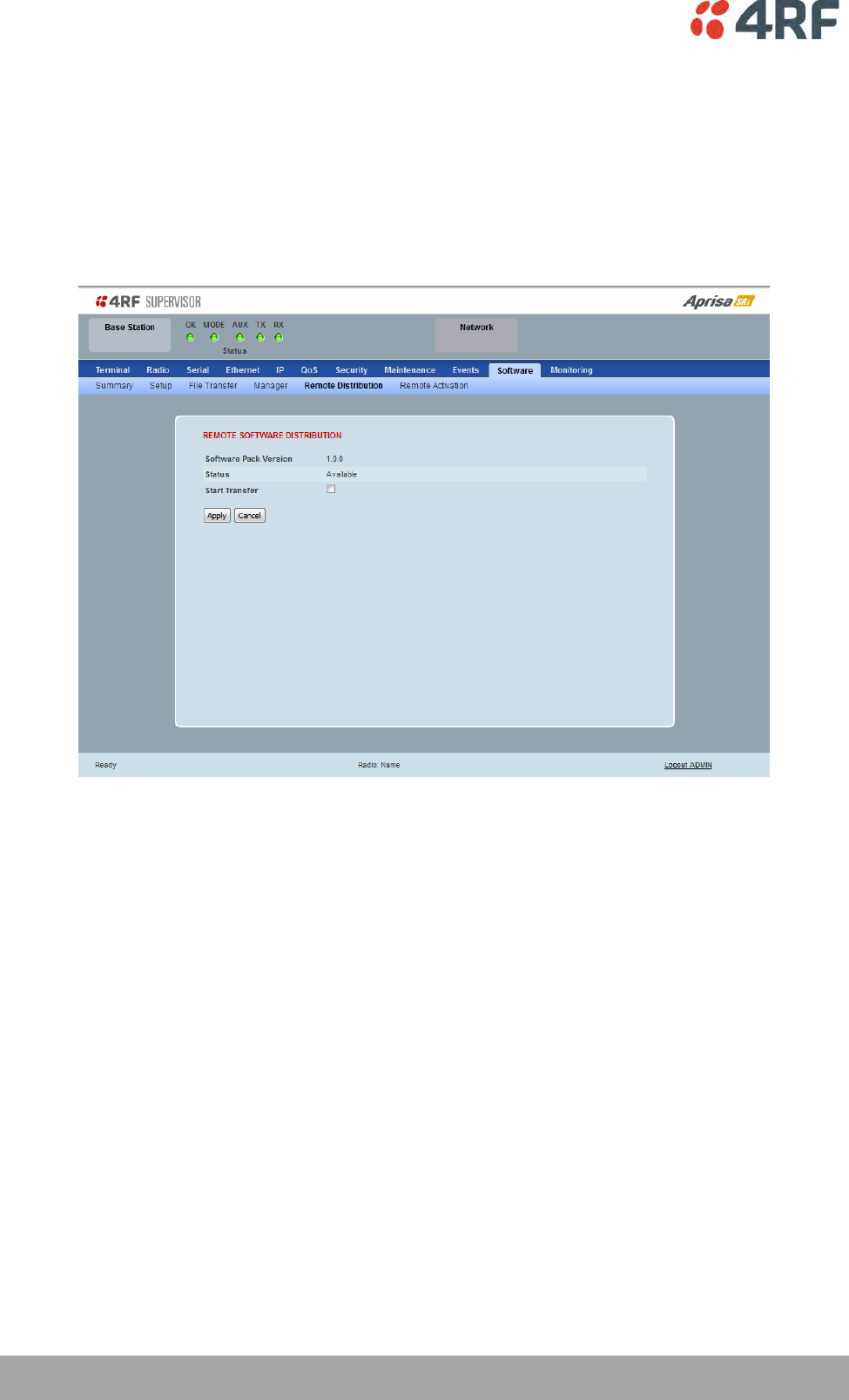
220 | Managing the Radio
Aprisa SRi User Manual 1.0.0
Software > Remote Distribution
This page provides the mechanism to distribute software to all remote stations into the Aprisa SRi network
(network) and then activate it.
The Software Pack that was loaded into the base station with the file transfer process (see ‘Software >
File Transfer’ on page 212) can be distributed via the radio link to all remote stations.
This page is used to manage the distribution of that software pack to all remote radios on the network.
This page is only available when the radio is configured as a Base Station.
REMOTE SOFTWARE DISTRIBUTION
Software Pack Version
This parameter displays the software pack version available for distribution on base station and activate
on all stations.
Status
This parameter displays the status of the software pack version.
If a Software Pack is not available, the status will display ‘Unavailable’ and the software distribution
mechanism will not work.
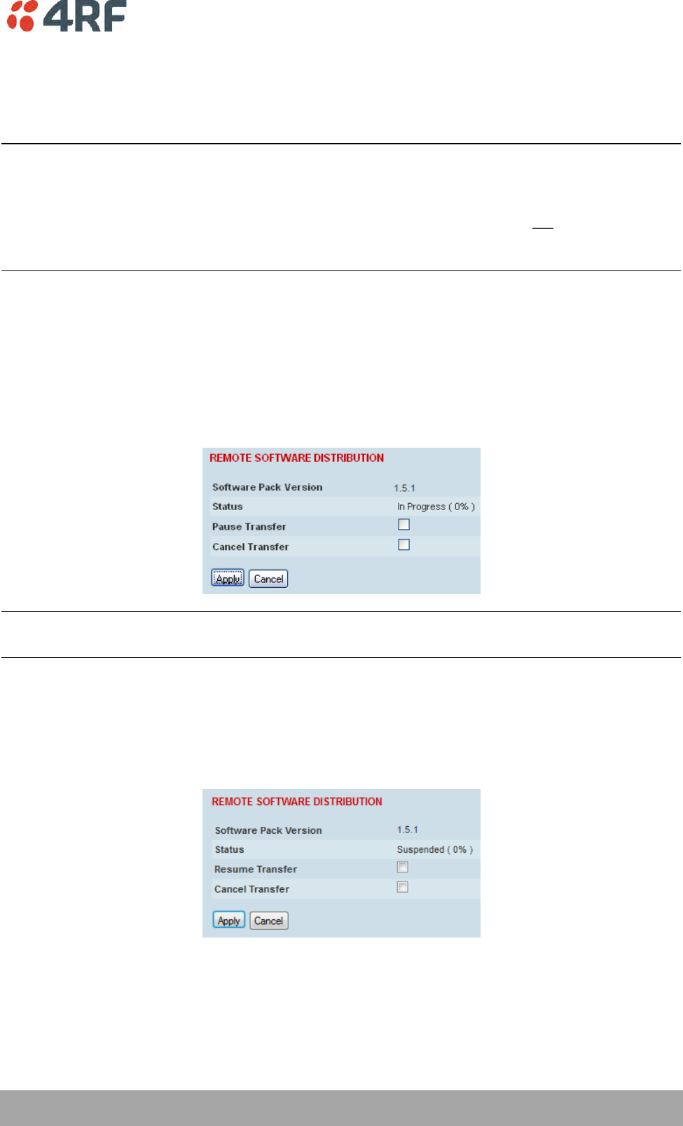
Managing the Radio | 221
Aprisa SRi User Manual 1.0.0
Start Transfer
This parameter when activated distributes (broadcasts) the new Software Pack to all remote stations in
the network.
Note: The distribution of software to remote stations does not stop customer traffic from being
transferred. However, due to the volume of traffic, the software distribution process may affect customer
traffic.
Software distribution traffic is classified as ‘management traffic’ but does not use the Ethernet
management priority setting. Software distribution traffic priority has a fixed priority setting of ‘very
low’.
To distribute software to remote stations:
This process assumes that a Software Pack has been loaded into the base station with the file transfer
process (see ‘Software > File Transfer’ on page 212).
1. To ensure that the Network Table is up to date, it is recommended running the node discover function
(see ‘Discover Nodes’ on page 193).
2. Click on ‘Start Transfer’.
Note: This process could take anywhere between 40 minutes and several hours depending on channel size,
Ethernet Management Priority setting and the amount of customer traffic on the network.
3. When the distribution is completed, activate the software with the Remote Software Activation.
Pause Transfer
This parameter when activated, pauses the distribution process and shows the distribution status. The
distribution process will continue from where it was paused with Resume Transfer.
Cancel Transfer
This parameter when activated, cancels the distribution process immediately.
During the distribution process, it is possible to navigate away from this page and come back to it to check
progress. The SuperVisor session will not timeout.
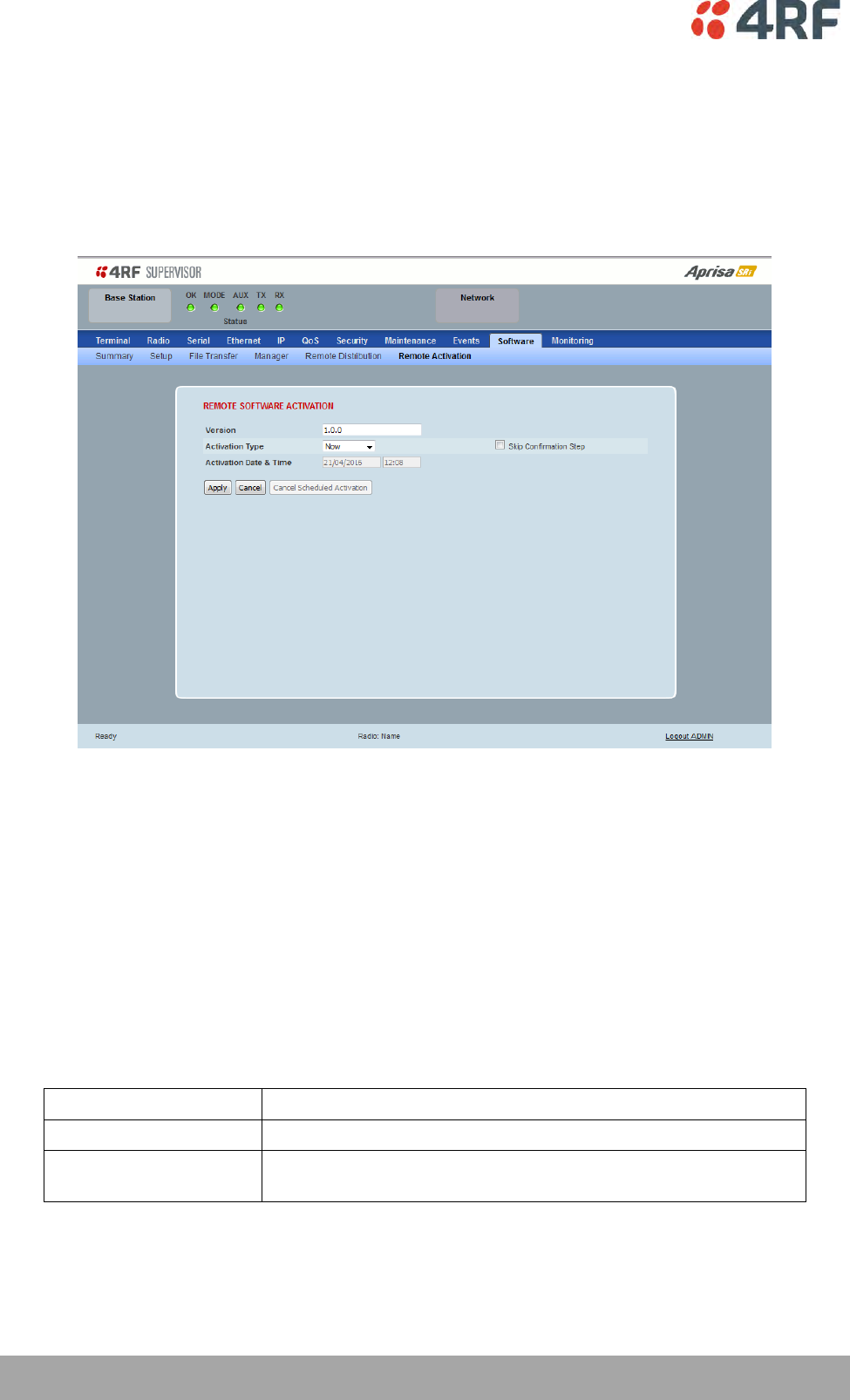
222 | Managing the Radio
Aprisa SRi User Manual 1.0.0
Software > Remote Activation
This page provides the mechanism to activate software on all remote stations.
The Software Pack was loaded into the base station with the file transfer process (see ‘Software > File
Transfer’ on page 212) and was distributed via the radio link to all remote stations.
This page is used to manage the activation of that software pack on all remote radios on the network.
This page is only available when the radio is configured as a Base Station.
REMOTE SOFTWARE ACTIVATION
When the software pack version has been distributed to all the remote stations, the software is then
activated in all the remote stations with this command. If successful, then activate the software pack in
the base station to complete the network upgrade.
Version
This parameter displays the software version for activation. The default version is the software pack
version but any valid software version can be entered in the format ‘n.n.n’.
Activation Type
This parameter sets when the software pack activation will occur.
Option
Function
Now
Activates the software pack now.
Date & Time
Activates the software pack at the Date & Time set in the following
parameter.
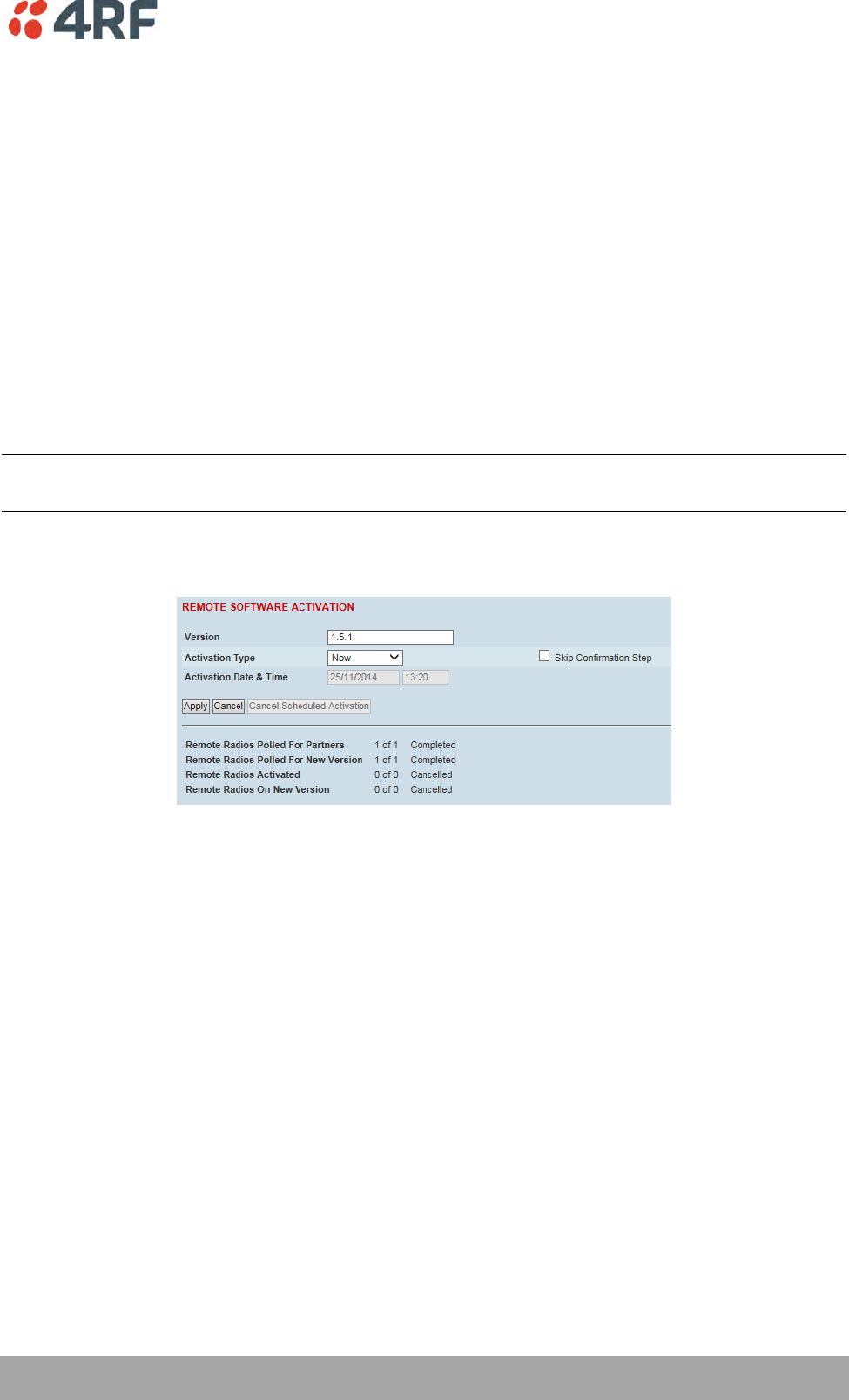
Managing the Radio | 223
Aprisa SRi User Manual 1.0.0
Activation Date & Time
This parameter sets the Date & Time when the software pack activation will occur.
This setting can be any future date and 24 hour time.
Skip Confirmation Step
This parameter when enabled skips the confirmation step during the activation process.
Normally, the confirmation step will require use intervention to accept the confirmation which will halt
the activation process. Skipping the confirmation will enable the activation process to continue without
use intervention.
To activate software in remote stations:
This process assumes that a Software Pack has been loaded into the base station with the file transfer
process (see ‘Software > File Transfer’ on page 212) and distributed to all remote radios in the network.
Note: Do not navigate SuperVisor away from this page during the activation process (SuperVisor can lose
PC focus).
1. Enter the Software Pack version (if different from displayed version).
2. Select the Activation type.
3. Click Apply.
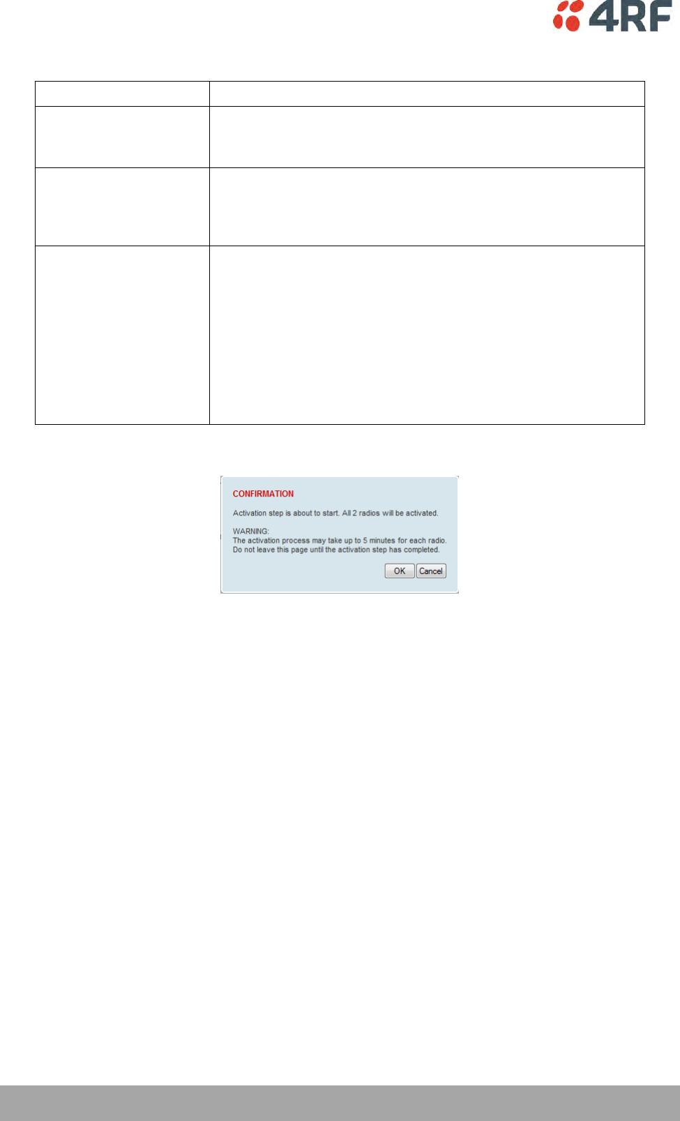
224 | Managing the Radio
Aprisa SRi User Manual 1.0.0
The remote stations will be polled to determine which radios require activation:
Result
Function (X of Y)
Remote Radios Polled for
New Version
X is the number of radios polled to determine the number of radios
that contain the new software version.
Y is the number of remote radios registered with the base station.
Remote Radios Activated
X is the number of radios that contain the new software version
and have been activated.
Y is the number of radios that contain the new software version
and can be activated.
Remote Radios On New
Version
X is the number of radios that has been successfully activated and
now running the new version of software.
Y is the number of radios that the activation command was
executed on.
Note: When upgrading from software version 1.2.5 to 1.2.6 or
later, communication to all remote radios will be lost due to a MAC
protocol change. This will prevent this function from working
correctly. In this case, activate the new software on the base
station and run the ‘Maintenance > Advanced’ Discover Nodes
function on page 192.
When the activation is ready to start:
4. Click on ‘OK’ to start the activation process or Cancel to quit.
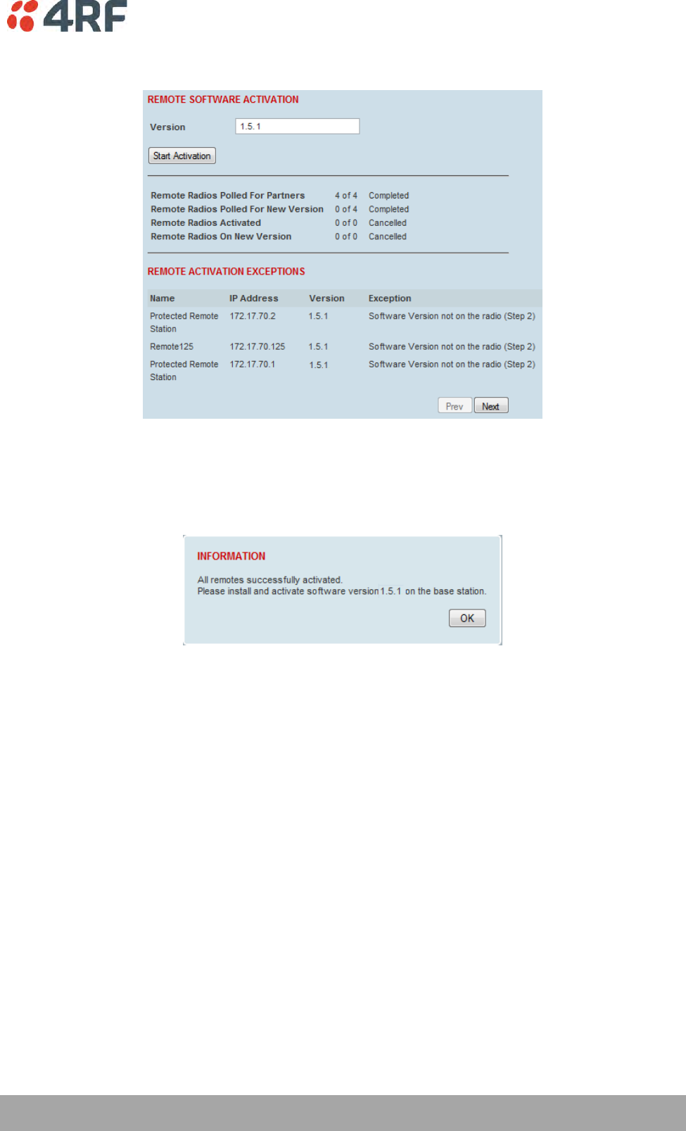
Managing the Radio | 225
Aprisa SRi User Manual 1.0.0
The page will display the progress of the activation.
The example shows that during the activation process there were exceptions that may need to be
investigated.
When all the remote radios have been activated, the base station radio must now be activated with (see
‘Software > Manager’ on page 216).
4. Click on ‘OK’ to start the activation on the base station.
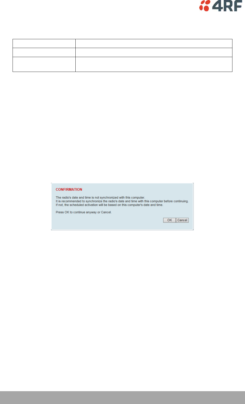
226 | Managing the Radio
Aprisa SRi User Manual 1.0.0
Activation Type
This parameter sets when the remote software activation will occur.
Option
Function
Now
Activates the remote software now.
Date & Time
Activates the remote software at the Date & Time set in the
following parameter.
Skip Confirmation Step
This parameter when enabled skips the confirmation step during the activation process.
Normally, the confirmation step will require use intervention to accept the confirmation which will halt
the activation process. Skipping the confirmation will enable the activation process to continue without
use intervention.
Activation Date & Time
This parameter sets the Date & Time when the remote software activation will occur.
This setting can be any future date and 24 hour time.
When the date and time is set, the remotes will be polled to setup the scheduled activation date and
time.
If the network base station radio date / time is not synchronized, you will get the following popup:
You can manually enter the base station radio date / time or use the Date And Time Synchronization from
a SNTP server feature (see ‘Terminal > Date / Time’ on page 84).
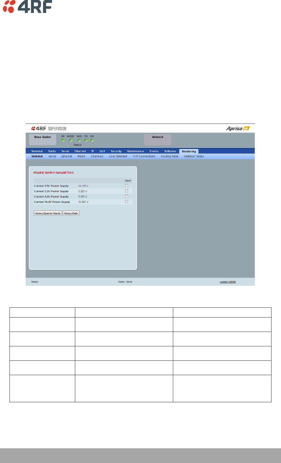
Managing the Radio | 227
Aprisa SRi User Manual 1.0.0
Monitoring
The Terminal, Serial, Ethernet, Radio and User Selected Monitored Parameter results have history log
views for both Quarter Hourly and Daily.
Monitored parameter data is accumulated into 2 sets:
15 minutes of data, for 96 readings for the last 24 hours
24 hours of data, for 31 readings for the last 31 days.
Monitoring > Terminal
This page displays the current radio internal and external input source radio power supply voltage
diagnostic parameters.
POWER SUPPLY PARAMETERS
Monitored Parameter
Function
Normal Operating Limits
Current VDC Power Supply
Parameter to show the current power
supply input voltage
10 to 30 VDC
Current 3.3 Volts Power
Supply
Parameter to show the current 3.3 volt
power rail voltage
3.1 to 3.5 VDC
Current 5.0 Volts Power
Supply
Parameter to show the current that the
current 5.0 volt power rail voltage
4.7 to 5.5 VDC
Current 7.2 Volts Power
Supply
Parameter to show the current that the
current 7.2 volt power rail voltage
6.9 to 7.5 VDC
Current 15 Volts Power
Supply
Parameter to show the current that the
current 15 volt power rail voltage.
The 15 volt power supply is used to power
the transmitter driver and power amplifier.
12.7 to 13.5 VDC
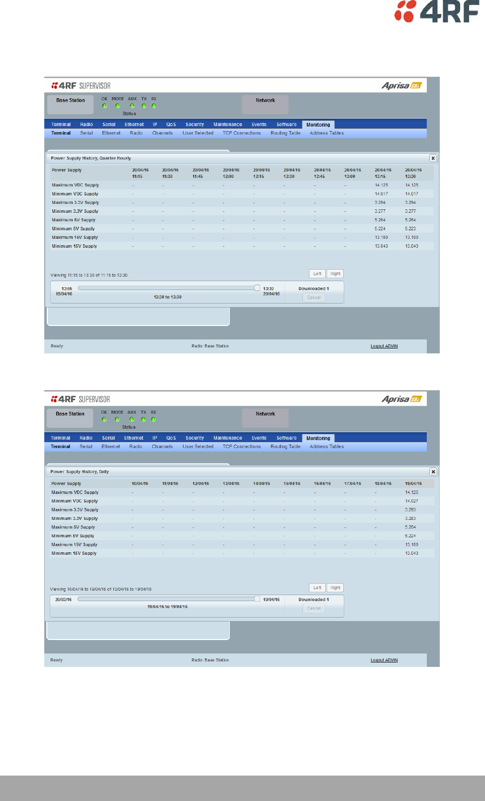
228 | Managing the Radio
Aprisa SRi User Manual 1.0.0
Controls
The History Quarter Hourly button presents a log of results every quarter of an hour.
The History Daily button presents a log of results every day.
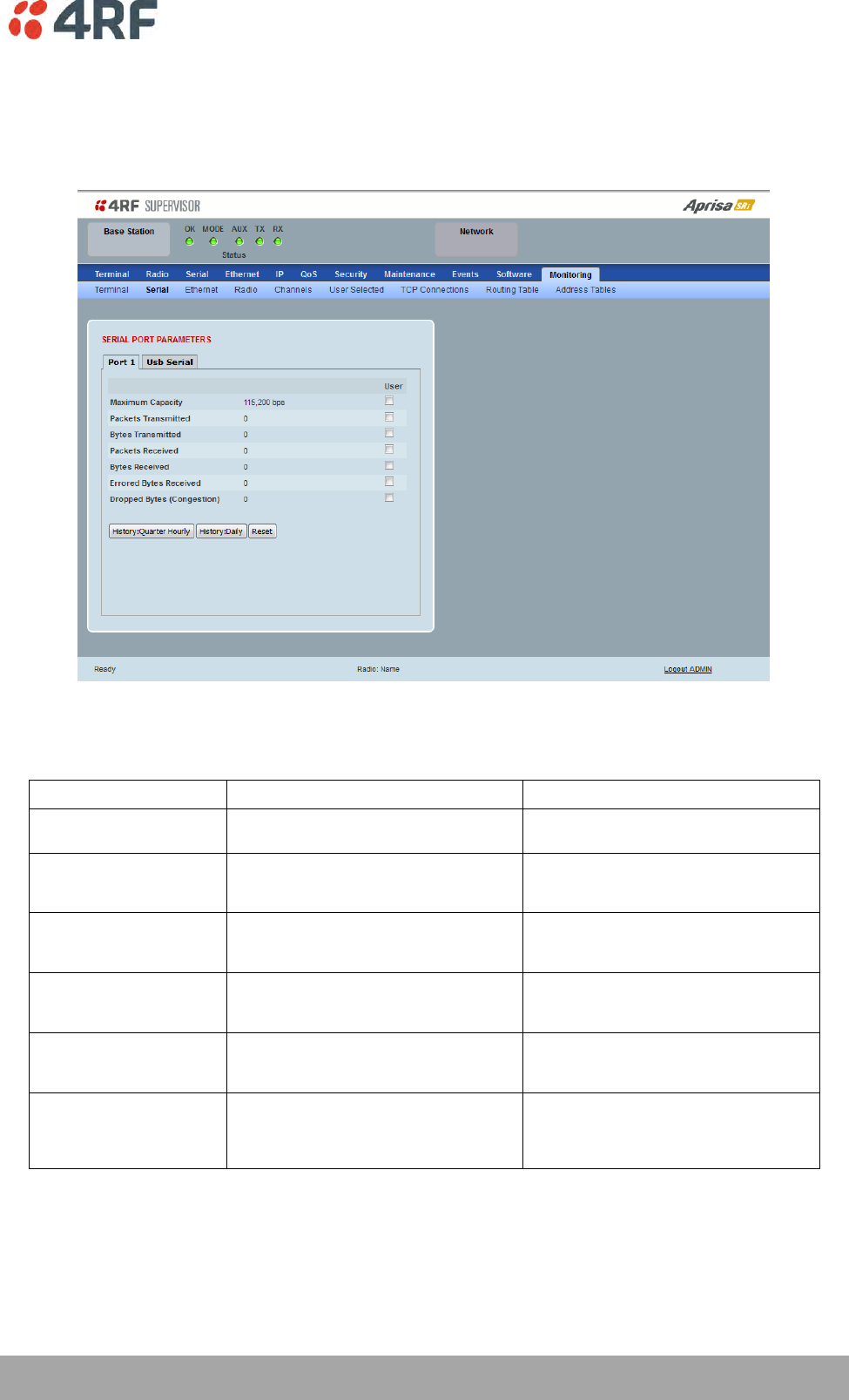
Managing the Radio | 229
Aprisa SRi User Manual 1.0.0
Monitoring > Serial
This page displays the current radio performance monitoring parameters per serial port in packet and byte
level granularity, for serial port high level statistics and troubleshooting.
The results shown are since the page was opened and are updated automatically every 12 seconds.
SERIAL PORT PARAMETERS
All Serial Ports
Monitored Parameter
Function
Normal Operating Limits
Maximum Capacity
Parameter to show the maximum serial
data rate of the serial port
Equal to the serial port baud rate setting
Packets Transmitted
Parameter to show the number of packets
transmitted to the customer from the serial
port
Packets Received
Parameter to show the number of packets
received from the customer into the serial
port
Bytes Received
Parameter to show the number of bytes
received from the customer into the serial
port
Errored Bytes Received
Parameter to show the number of bytes
received from the customer into the serial
port that have errors
Dropped Bytes (Congestion)
Parameter to show the number of bytes
received from the customer into the serial
port that are dropped due to over the air
congestion
Controls
The Reset button clears the current results.
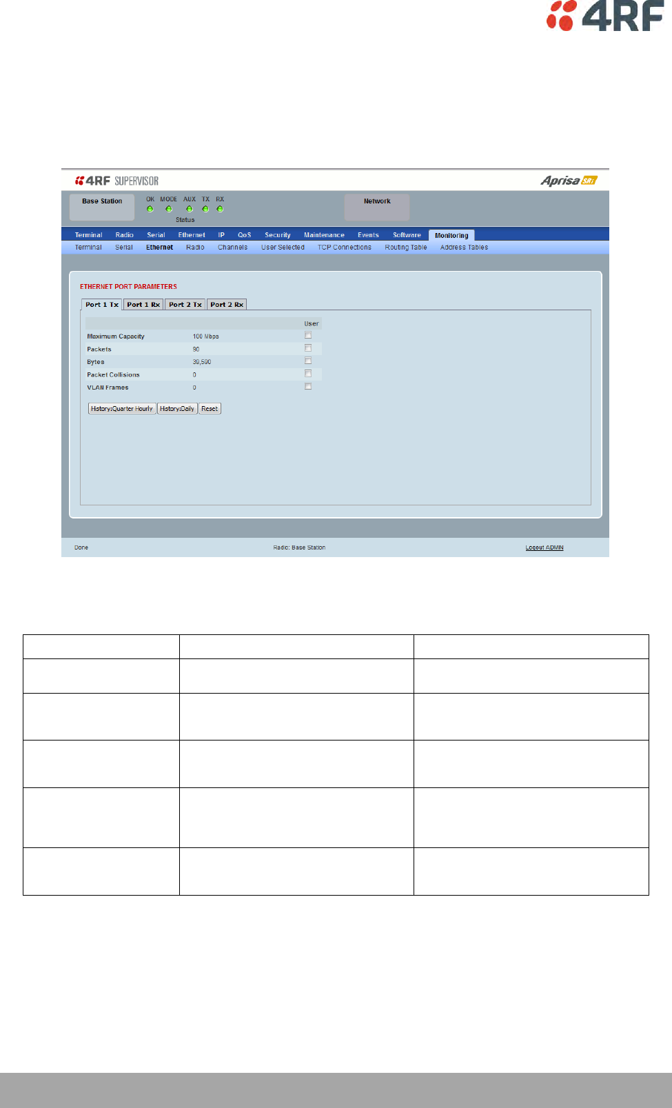
230 | Managing the Radio
Aprisa SRi User Manual 1.0.0
Monitoring > Ethernet
This page displays the current radio performance monitoring parameters per Ethernet port transmission
(TX) out of the radio in packet and byte level granularity, for Ethernet port high level statistics and
troubleshooting.
The results shown are since the page was opened and are updated automatically every 12 seconds.
ETHERNET PORT PARAMETERS
All Ethernet Ports TX
Monitored Parameter
Function
Normal Operating Limits
Maximum Capacity
Parameter to show the maximum Ethernet
data rate of the Ethernet port
Equal to the Ethernet port speed setting
Packets
Parameter to show the number of packets
transmitted to the customer from the
Ethernet port
Bytes
Parameter to show the number of bytes
transmitted to the customer from the
Ethernet port
Packet Collisions
Parameter to show the number of packet
collisions on the data transmitted to the
customer from the Ethernet port on a
shared LAN
VLAN Frames
Parameter to show the number of VLAN
tagged frames transmitted to the customer
from the Ethernet port
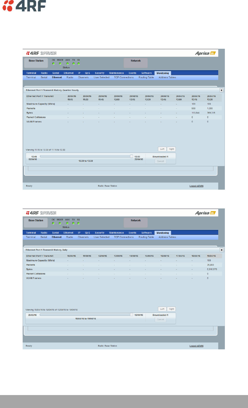
Managing the Radio | 231
Aprisa SRi User Manual 1.0.0
Controls
The Reset button clears the current results.
The History Quarter Hourly button presents a log of results every quarter of an hour.
The History Daily button presents a log of results every day.
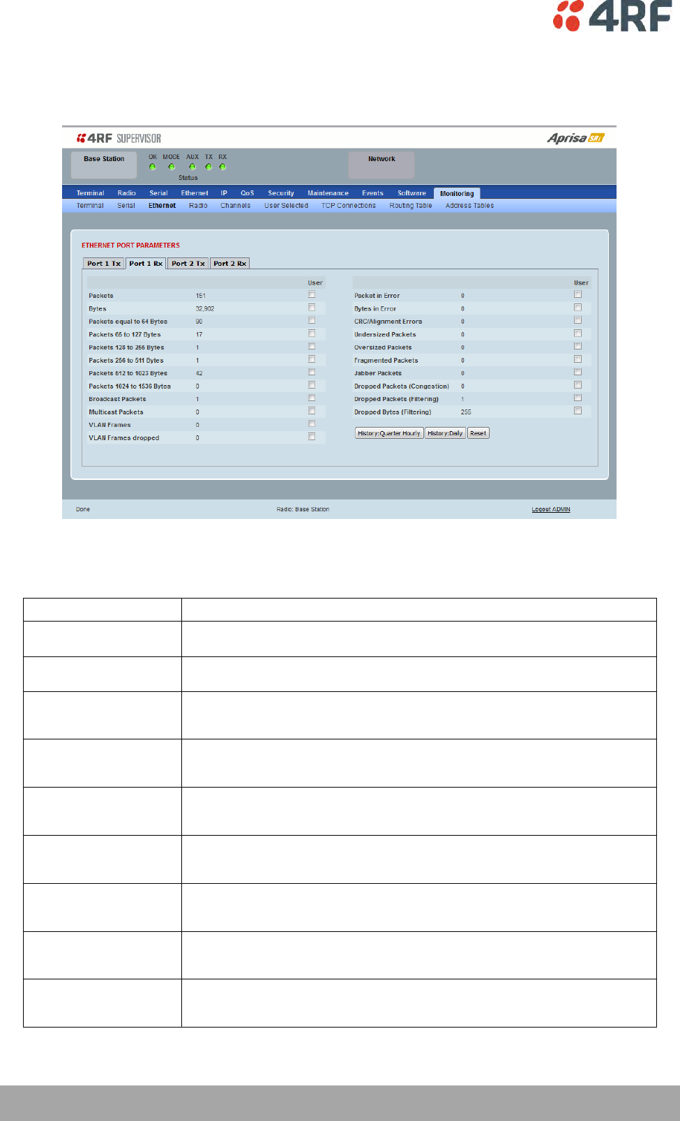
232 | Managing the Radio
Aprisa SRi User Manual 1.0.0
This page displays the current radio performance monitoring parameters per Ethernet port received (RX)
data in packet and byte level granularity, for Ethernet port high level statistics and troubleshooting.
The results shown are since the page was opened and are updated automatically every 12 seconds.
ETHERNET PORT PARAMETERS
All Ethernet Ports RX
Monitored Parameter
Function
Packets
Parameter to show the number of packets received by the customer from the Ethernet
port (including bad packets, broadcast packets, and multicast packets)
Bytes
Parameter to show the number of bytes received (including those in bad packets) by the
customer from the Ethernet port (excluding framing bits but including FCS octets)
Packets equal to 64 bytes
Parameter to show the number of packets received (including bad packets) from the
customer into the Ethernet port that are equal to 64 bytes (excluding framing bits but
including FCS octets)
Packets 65 to 127 bytes
Parameter to show the number of packets received (including bad packets) from the
customer into the Ethernet port that are between 65 and 127 bytes (excluding framing
bits but including FCS octets)
Packets 128 to 255 bytes
Parameter to show the number of packets received (including bad packets) from the
customer into the Ethernet port that are between 128 and 255 bytes (excluding framing
bits but including FCS octets)
Packets 256 to 511 bytes
Parameter to show the number of packets received (including bad packets) from the
customer into the Ethernet port that are between 256 and 511 bytes(excluding framing
bits but including FCS octets)
Packets 512 to 1023 bytes
Parameter to show the number of packets received (including bad packets) from the
customer into the Ethernet port that are between 512 and 1023 bytes(excluding framing
bits but including FCS octets)
Packets 1024 to 1536 bytes
Parameter to show the number of packets received (including bad packets) from the
customer into the Ethernet port that are between 1024 and 1536 bytes(excluding framing
bits but including FCS octets)
Broadcast Packets
Parameter to show the number of broadcast packets received from the customer into the
Ethernet port. Broadcast packets are good packets received that were directed to the
broadcast address. Note that this does not include multicast packets.

Managing the Radio | 233
Aprisa SRi User Manual 1.0.0
Monitored Parameter
Function
Multicast Packets
Parameter to show the number of multicast packets received from the customer into the
Ethernet port. Multicast packets are packets that were directed to a multicast address.
Note that this number does not include packets directed to the broadcast address.
VLAN Frames
Parameter to show the number of VLAN tagged frames received from the customer into
the Ethernet port
VLAN Frames Dropped
Parameter to show the number of VLAN tagged frames received from the customer into
the Ethernet port that were dropped due to CRC errored frames, filtered VLAN frames,
undersized frames or oversized frames.
Packet In Error
Parameter to show the number of errored packets received from the customer into the
Ethernet port caused by CRC errors, FCS Errors, alignment errors, oversized packets,
undersized packets, fragmented packets and jabber packets
Bytes In Error
Parameter to show the number of errored bytes received from the customer into the
Ethernet port
CRC / Alignment Error
Parameter to show the number of CRC / alignment errors received from the customer into
the Ethernet port. CRC / alignment errors are defined as frames that had a length
excluding framing bits, but including FCS octets of between 64 and 1518 octets, inclusive,
but had either a bad Frame Check Sequence (FCS) with an integral number of octets (FCS
Error) or a bad FCS with a non-integral number of octets.
Undersized Packets
Parameter to show the number of undersized packets received from the customer into the
Ethernet port. Undersized packets are less than 64 octets long excluding framing bits, but
including FCS octets.
Oversized Packets
Parameter to show the number of oversized packets received from the customer into the
Ethernet port. Oversized packets are longer than 1518 octets excluding framing bits, but
including FCS octets.
Fragmented Packets
Parameter to show the number of fragmented packets received from the customer into
the Ethernet port. Fragmented packets have either a bad Frame Check Sequence (FCS)
with an integral number of octets (FCS Error) or a bad FCS.
Jabber Packets
Parameter to show the number of jabber packets received from the customer into the
Ethernet port
Dropped Packets
(congestion)
Parameter to show the number of dropped packets received from the customer into the
Ethernet port caused by congestion
Dropped Packets (filtering)
Parameter to show the number of dropped packets received from the customer into the
Ethernet port caused by packet L2 / L3 filtering
Dropped Bytes (filtering)
Parameter to show the number of dropped bytes received from the customer into the
Ethernet port caused by packet L2 / L3 filtering
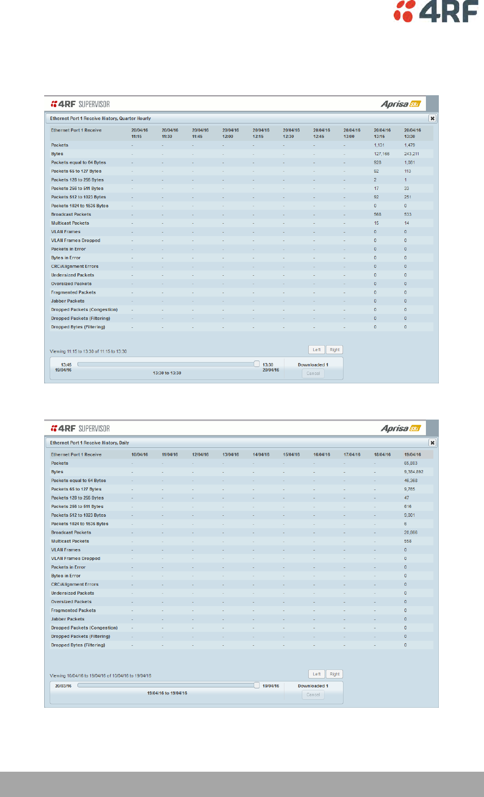
234 | Managing the Radio
Aprisa SRi User Manual 1.0.0
Controls
The Reset button clears the current results.
The History Quarter Hourly button presents a log of results every quarter of an hour.
The History Daily button presents a log of results every day.
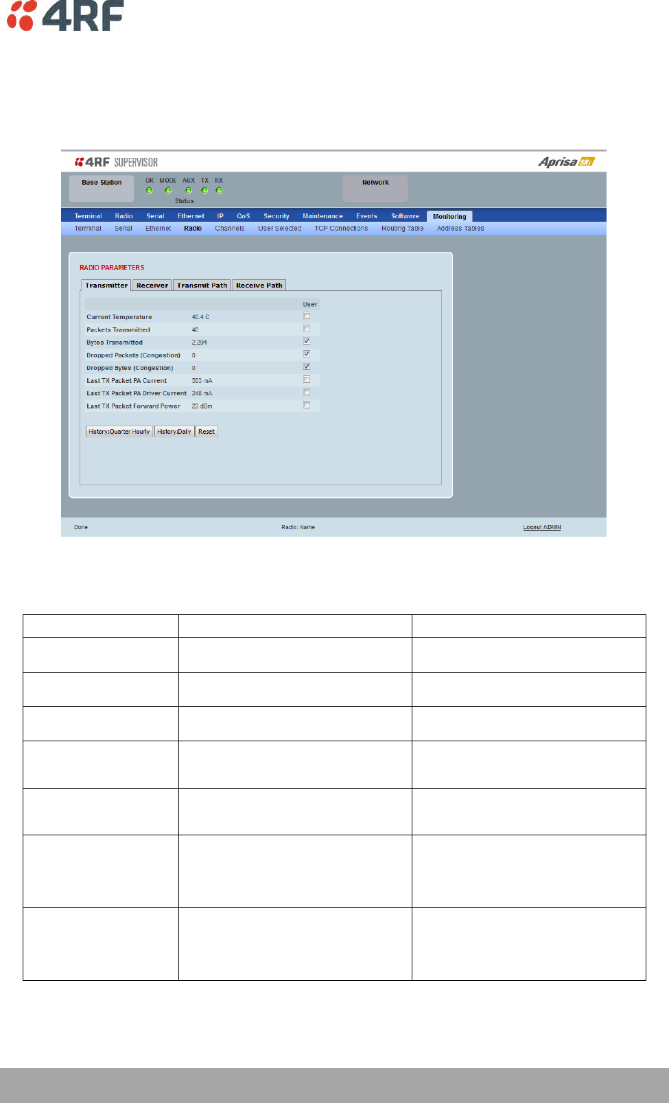
Managing the Radio | 235
Aprisa SRi User Manual 1.0.0
Monitoring > Radio
This page displays the current radio diagnostic and performance monitoring parameters of the radio
transmitter.
The results shown are since the page was opened and are updated automatically every 12 seconds.
RADIO PARAMETERS
Transmitter
Monitored Parameter
Function
Normal Operating Limits
Current Temperature
Parameter to show the current
temperature of the transmitter
0 to 70 °C
Packets Transmitted
Parameter to show the number of packets
transmitted over the air
Bytes Transmitted
Parameter to show the number of bytes
transmitted over the air
Dropped Packets
(congestion)
Parameter to show the number of dropped
packets transmitted over the air caused by
congestion
Dropped Bytes (congestion)
Parameter to show the number of dropped
bytes transmitted over the air caused by
congestion
Last TX Packet PA Current
Parameter to show the current consumed
by the transmitter power amplifier in mA.
The value is stored from the last time the
transmitter was active and transmitted a
packet.
This value will change depending on the
transmitter power setting, modulation,
temperature and the VSWR of the antenna.
The alarm limits for this are 50 mA to 2.5 A
Last TX Packet Driver
Current
Parameter to show the current consumed
by the transmitter power amplifier driver
in mA. The value is stored from the last
time the transmitter was active and
transmitted a packet.
This value will change depending on the
transmitter power setting, modulation and
temperature. The alarm limits for the PA
Driver Current are 10 mA to 500 mA.

236 | Managing the Radio
Aprisa SRi User Manual 1.0.0
Monitored Parameter
Function
Normal Operating Limits
Last TX Packet Forward
Power
Parameter to show the actual transmitter
power in dBm. The value is stored from the
last time the transmitter was active and
transmitted a packet.
This value will be dependent on the output
power, the temperature and the VSWR of
the antenna. The alarm limits for the Tx
forward power are +/-4 dB.
Controls
The Reset button clears the current results.
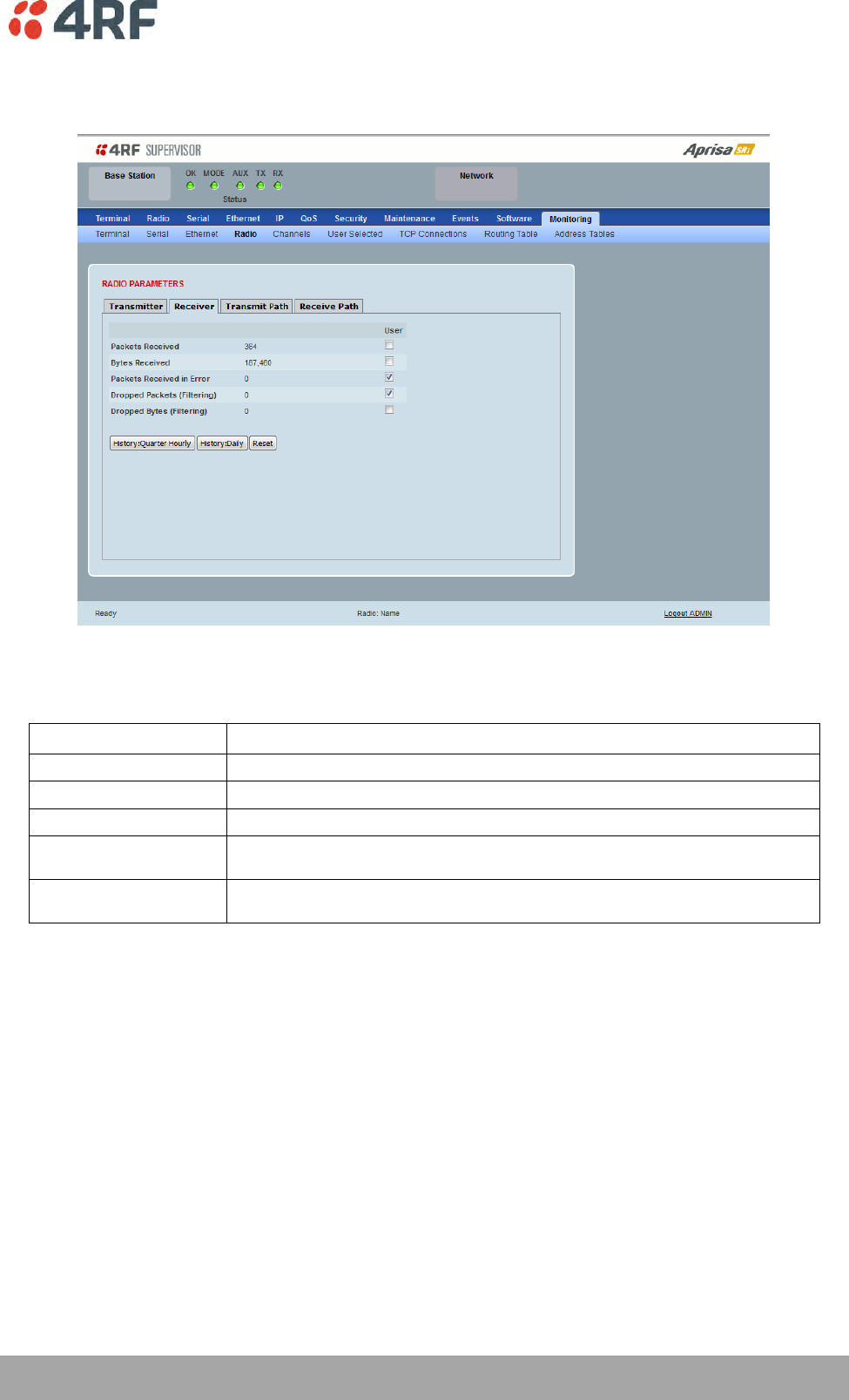
Managing the Radio | 237
Aprisa SRi User Manual 1.0.0
This page displays the current radio performance monitoring parameters of radio receiver.
The results shown are since the page was opened and are updated automatically every 12 seconds.
RADIO PARAMETERS
Receiver
Monitored Parameter
Function
Packets Received
Parameter to show the number of packets received over the air
Bytes Received
Parameter to show the number of bytes received over the air
Packets Received In Error
Parameter to show the number of packets received over the air
Dropped Packets (filtering)
Parameter to show the number of dropped packets received over the air caused by L2 / L3
filtering
Dropped Bytes (filtering)
Parameter to show the number of dropped bytes received over the air caused by L2 / L3
filtering
Controls
The Reset button clears the current results.
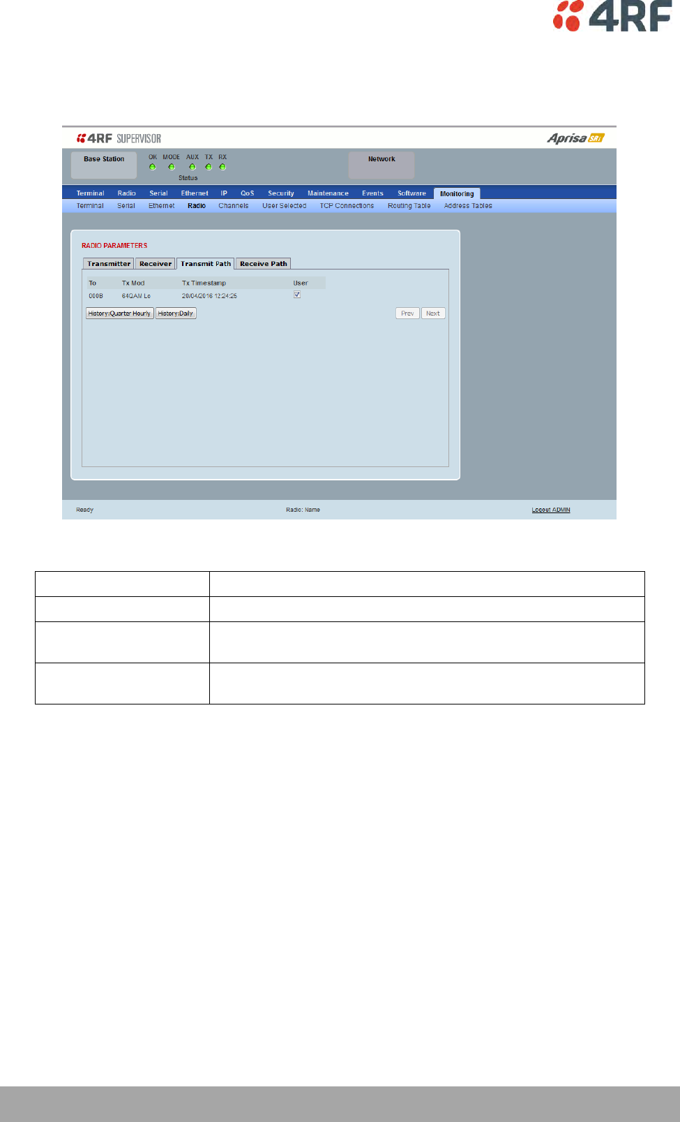
238 | Managing the Radio
Aprisa SRi User Manual 1.0.0
This page displays the current radio RF transmit path modulation setting to single or multiple destination
radios that the radio is transmitting to.
The results shown are since the page was opened and are updated automatically every 12 seconds.
RADIO PARAMETERS
Result
Function
To
The destination Node Address of the radio/s transmitting data to.
Tx Mod
The current radio transmitter modulation being used to
communicate with the destination radio/s.
Tx Timestamp
The timestamp of the last transmitted packet to the destination
radio/s.
Controls
The Next button will display the next page of 8 radios and the Prev button will display the previous page
of 8 radios.
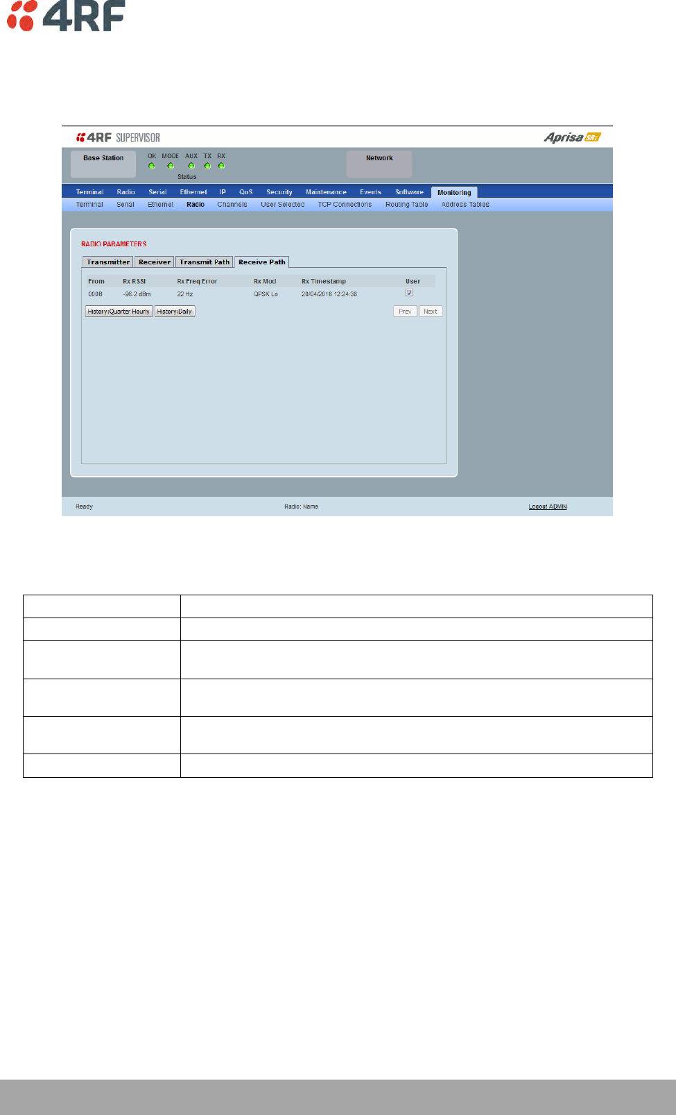
Managing the Radio | 239
Aprisa SRi User Manual 1.0.0
This page displays the current radio RF receive path parameters from single or multiple source radios that
the radio is receiving from.
The results shown are since the page was opened and are updated automatically every 12 seconds.
RADIO PARAMETERS
Receive Path
Result
Function
From
The source Node Address of the radio receiving data from.
Rx RSSI
The RSSI of the RF signal received from the source radio/s. This parameter
displays the receiver RSSI reading taken from the last data packet received.
Rx Freq Error
The frequency difference between this radio’s receiver and the frequency of the
incoming packet rate from the source radio/s.
Rx Mod
The current radio receive modulation being used to communicate with the source
radio/s.
Rx Timestamp
The timestamp of the last received packet from the source radio/s.
Controls
The Next button will display the next page of 8 radios and the Prev button will display the previous page
of 8 radios.
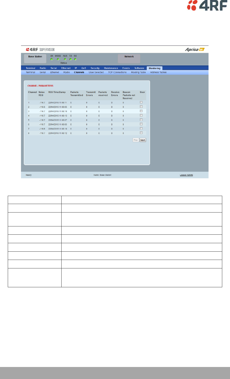
240 | Managing the Radio
Aprisa SRi User Manual 1.0.0
Monitoring > Channels
This page displays the current radio diagnostic and performance monitoring parameters of the channels.
The results shown are since the page was opened and are updated automatically every 12 seconds.
CHANNEL PARAMETERS
Result
Function
Channel
The channel number.
Noise RSSI
The RSSI measured when the channel is clear. It is used to determine if
interference is present.
RSSI Timestamp
The timestamp of the last received packet used for RSSI.
Packets Transmitted
The number of packets transmitted from the radio.
Transmit Errors
The number of transmit packets not acknowledged by the base station.
Packets Received
The number of packets received by the radio.
Receive Errors
The number of errored packets received by the radio.
Beacon Packets Not
Received
The base station sends broadcast beacon packets to the remotes to sync
to the hop channels. This is the number of Beacon Packets not received at
the remotes.
Controls
The Next button will display the next page of 8 connections and the Prev button will display the previous
page of 8 connections.
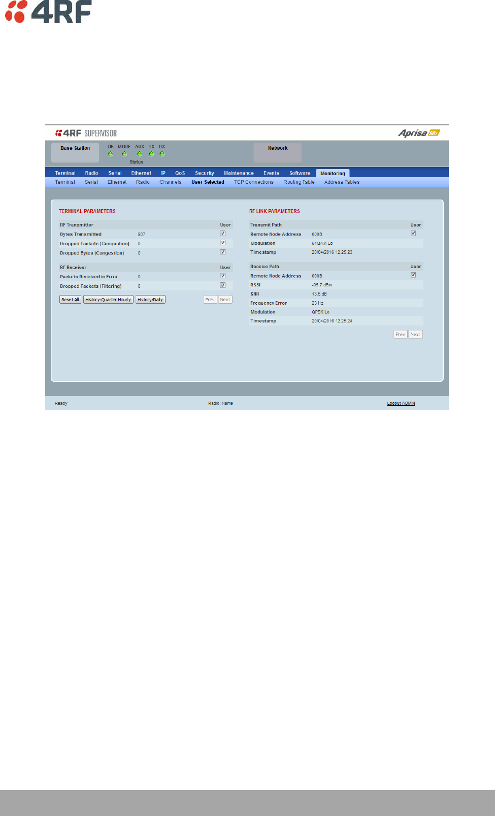
Managing the Radio | 241
Aprisa SRi User Manual 1.0.0
Monitoring > User Selected
This page displays the ‘User’ parameters setup in all the other Monitoring screens e.g. in the Monitoring >
Radio > Transmitter, the User checkbox is ticked for the Dropped Packets (Congestion) and Dropped Bytes
(Congestion).
The results shown are since the page was opened and are updated automatically every 12 seconds.
Controls
The Reset button clears the current results.
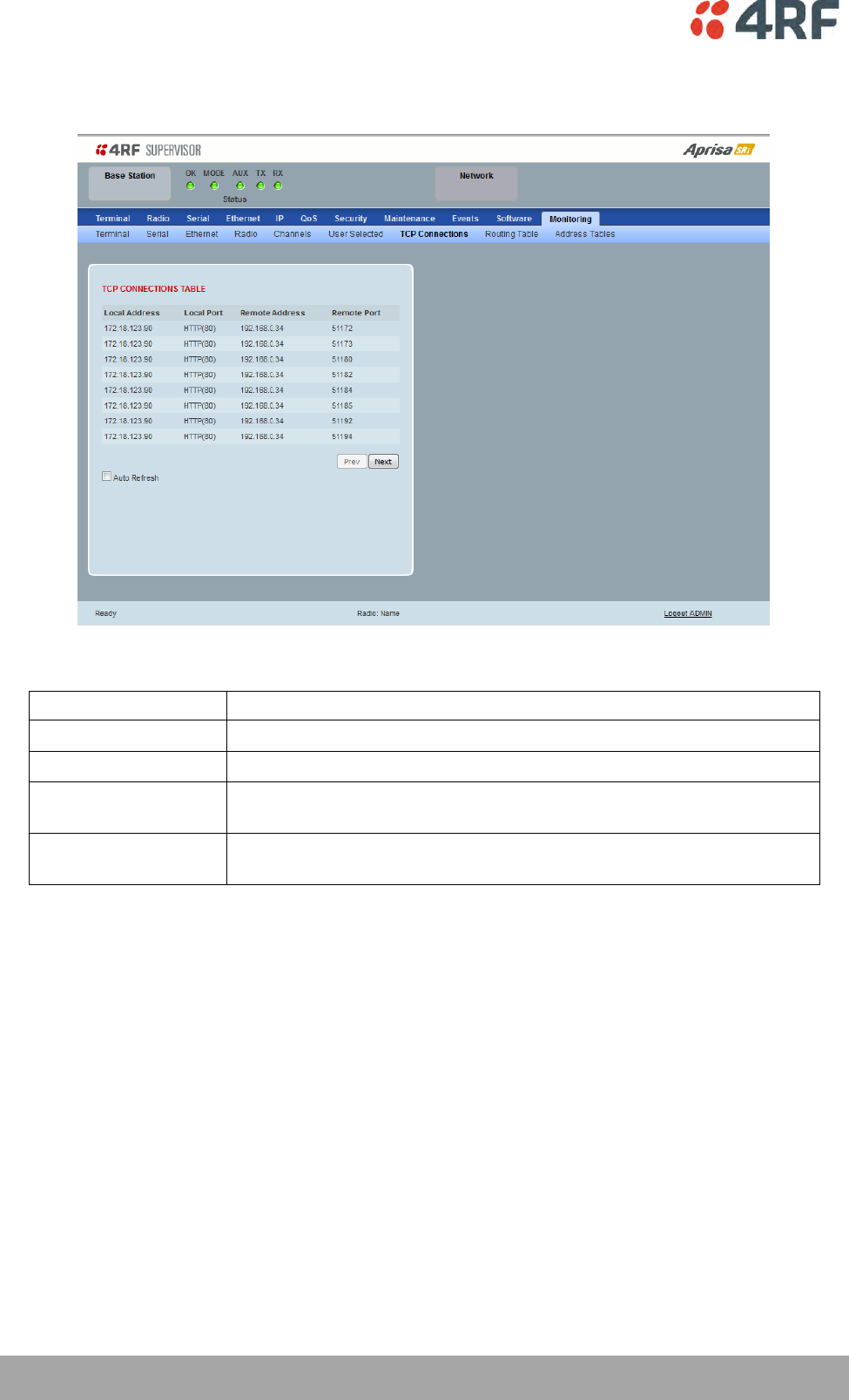
242 | Managing the Radio
Aprisa SRi User Manual 1.0.0
Monitoring > TCP Connections
This page displays the list of active TCP connections on the radio.
TCP CONNECTIONS TABLE
Result
Function
Local Address
The local radio IP address
Local Port
The local radio TCP port number
Remote Address
The remote host IP address (in most case a host PC connected to
radio/network)
Remote Port
The local radio TCP port number (in most case a host PC connected to
radio / network)
Controls
The Next button will display the next page of 8 connections and the Prev button will display the previous
page of 8 connections.
If the Auto Refresh option is ticked, the TCP Connections table will refresh every 12 seconds.

Managing the Radio | 243
Aprisa SRi User Manual 1.0.0
Monitoring > Routing Table
This page displays the list of active routes on the radio.
ROUTING TABLE
Result
Function
Index
The routing table index
Destination
The target destination IP address of the route
Mask
The subnet mask of the destination IP address of the route
Next Hop
The next hop IP address on the path to the destination IP address of the
route
Interface
The physical interface output on the path to the destination IP address of
the route
Controls
The Next button will display the next page of 8 routes and the Prev button will display the previous page
of 8 routes.
If the Auto Refresh option is ticked, the routing table will refresh every 12 seconds.
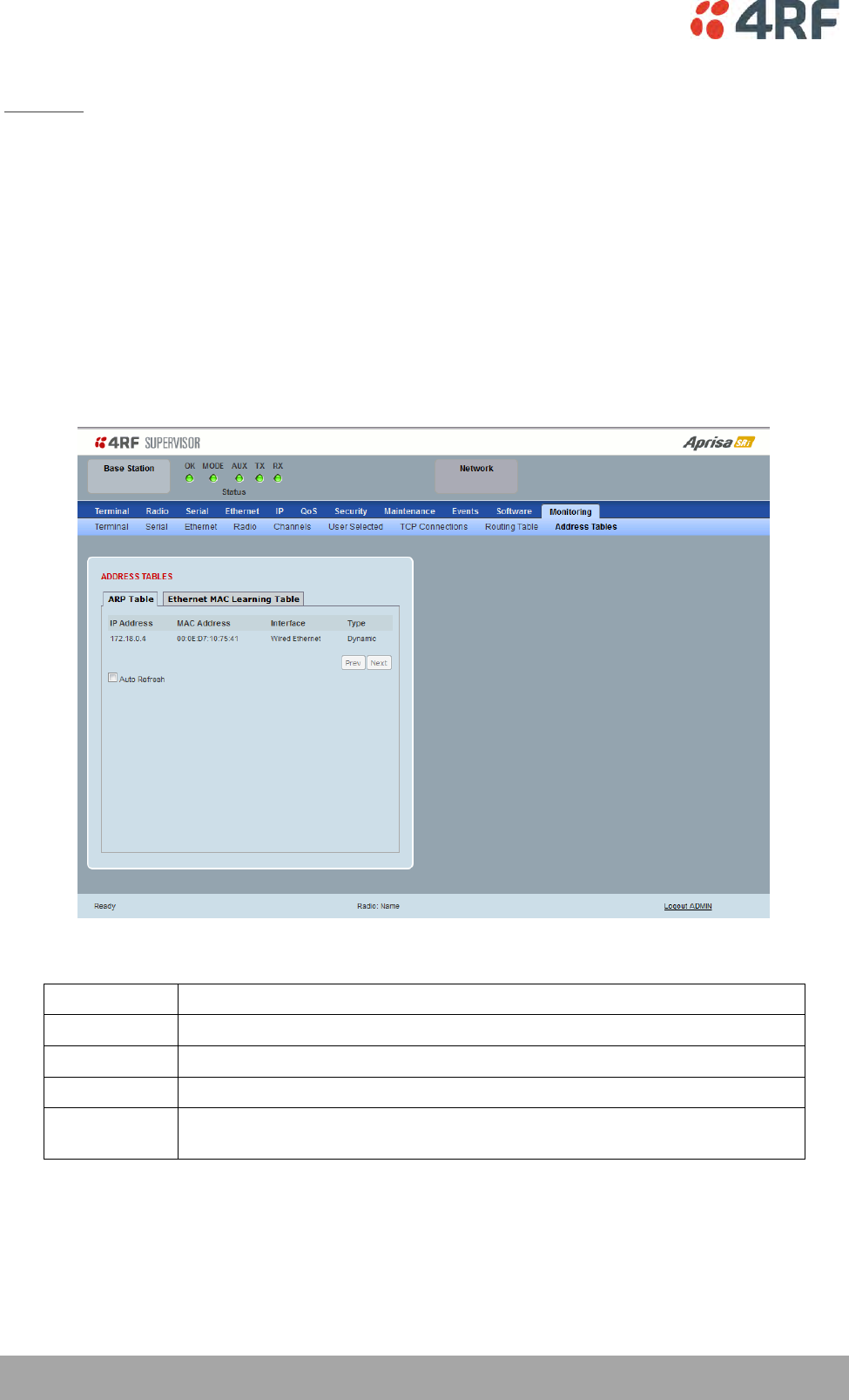
244 | Managing the Radio
Aprisa SRi User Manual 1.0.0
Monitoring > Address Tables
ARP Table
This page displays the current Address Resolution Protocols (ARP) on the radio. The radio implemented
ARP protocol is used for resolution of network layer addresses into link layer addresses. It is used to map a
IPv4 address to an Ethernet MAC address. The ARP table shows the results of the ARP protocol linkage
between IPv4 address and Ethernet MAC address of the devices attached to the radio.
In a layer 2 bridge LAN, an upper layer protocol may include the IP address of the destination, but since it
is an Ethernet LAN network, it also needs to know the destination MAC address. First, the radio uses a
cached ARP table to look up the IPv4 destination address for the matching MAC address records. If the
MAC address is found, it sends the IPv4 packet encapsulated in Ethernet frame with the found MAC
address. If the ARP cache table did not produce a result for the destination IPv4 address, the radio sends a
broadcast ARP message requesting an answer (of MAC address that matches) for IP address. The
destination device responds with its MAC address (and IP). The response information is cached in radios’
ARP table and the message can now be sent with the appropriate destination MAC address.
ADDRESS TABLES
Title
Function
IP Address
The IPv4 address of a neighboring device in the radio LAN network
MAC Address
The ARP result matching or mapping MAC address from the IPv4 address.
Interface
The Ethernet port interface the ARP results found the matching/mapping
Type
‘Dynamic’ indicates an ARP result and ‘Static’ indicates a user static
mapping.
Controls
The Next button will display the next page of 8 addresses and the Prev button will display the previous
page of 8 addresses.
If the Auto Refresh option is ticked, the ARP table will refresh every 12 seconds.
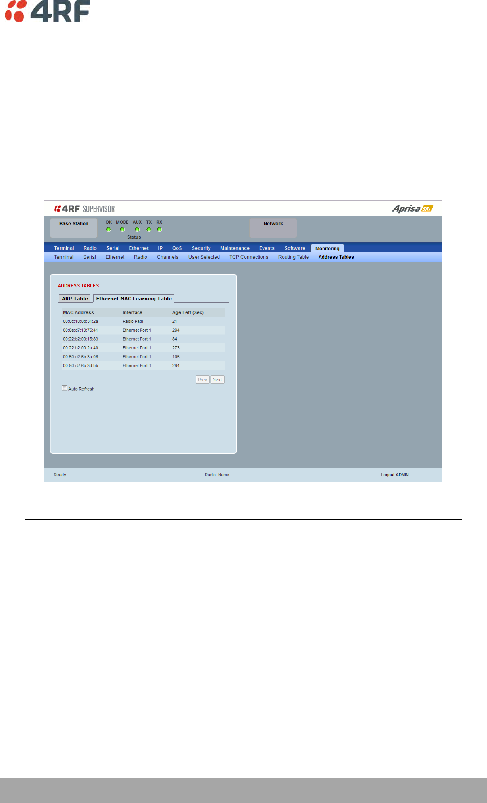
Managing the Radio | 245
Aprisa SRi User Manual 1.0.0
Ethernet MAC Learning Table
This page displays the current Ethernet Media Access Control (MAC) Address table on the radio LAN
network. In order for the radio to switch frames between Ethernet LAN ports efficiently, the radio layer 2
bridge maintains a MAC address table. When the radio bridge receives a frame, it associates the MAC
address of the sending network device with the LAN port on which it was received.
The bridge dynamically learns and builds the MAC address table by using the MAC source address of the
frames received. When the radio bridge receives a frame for a MAC destination address not listed in its
address table, it floods the frame to all LAN ports of the same LAN (or in case of VLAN, to the specific
VLAN) except the port that received the frame. When the destination bridge device replies, the radio
bridge adds its relevant MAC source address and interface port number to the MAC address table. The
switch then forwards subsequent frames to a single LAN port without flooding all LAN ports.
ADDRESS TABLES
Title
Function
MAC Address
The learned MAC address of a neighboring bridge device in the LAN network.
Interface
The Ethernet port interface the MAC address has learned
Age left
The aging time of this MAC entry will stay in the table, even if this MAC
address is not used. Every time this MAC address is used, the aging time
restarts from its maximum. Default is 300 sec.
Controls
The Next button will display the next page of 8 addresses and the Prev button will display the previous
page of 8 addresses.
If the Auto Refresh option is ticked, the routing table will refresh every 12 seconds.
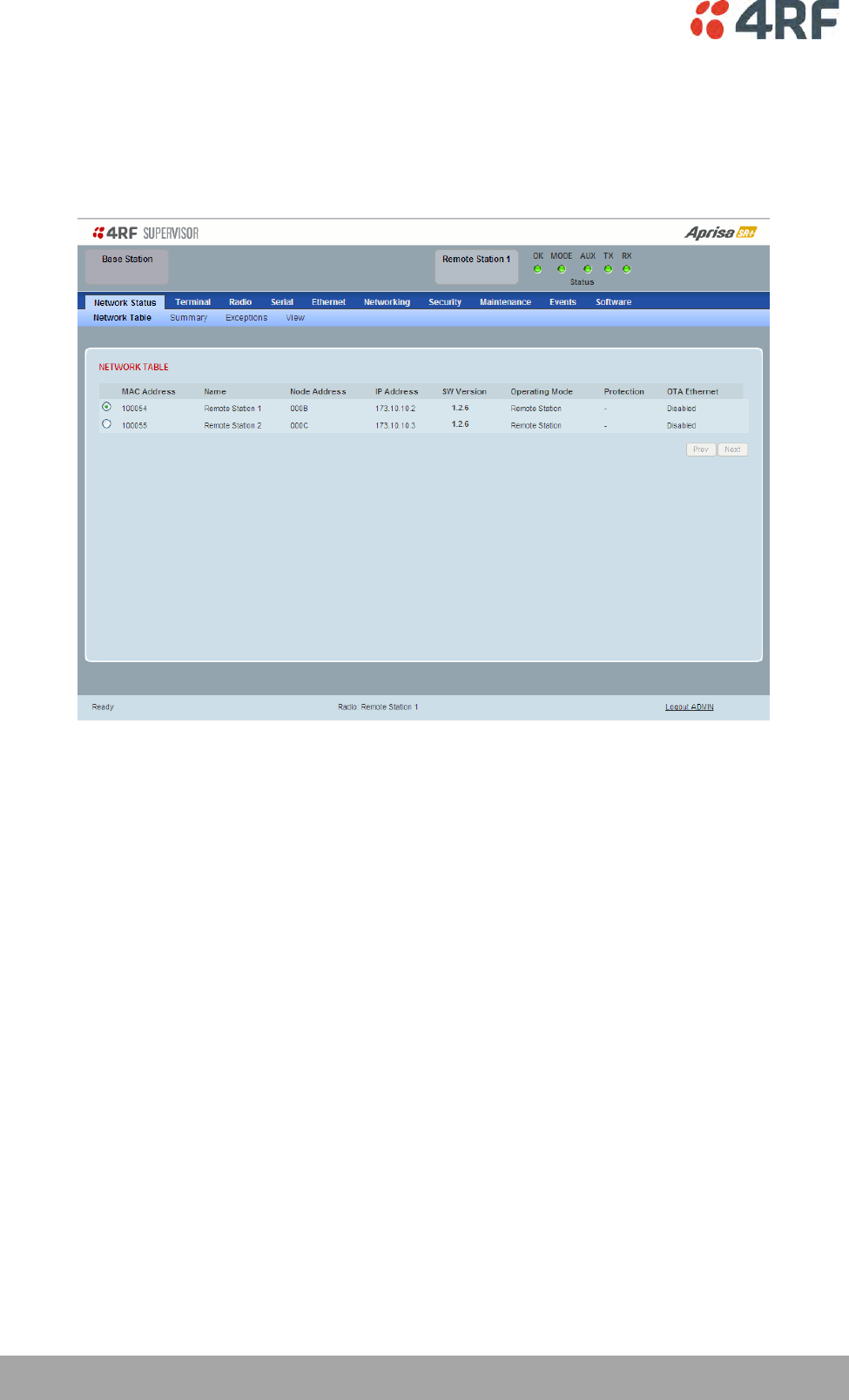
246 | Managing the Radio
Aprisa SRi User Manual 1.0.0
Network Status
Network Status > Network Table
This page displays a list of all the registered remote stations for the base station and provides
management access to each of the remote stations.
NETWORK TABLE
This Network Table is only available when the local radio is the base station i.e. SuperVisor is logged into
the base station.
To manage a remote station with SuperVisor:
Click on the radio button of the required station. The remaining menu items then apply to the selected
remote station.
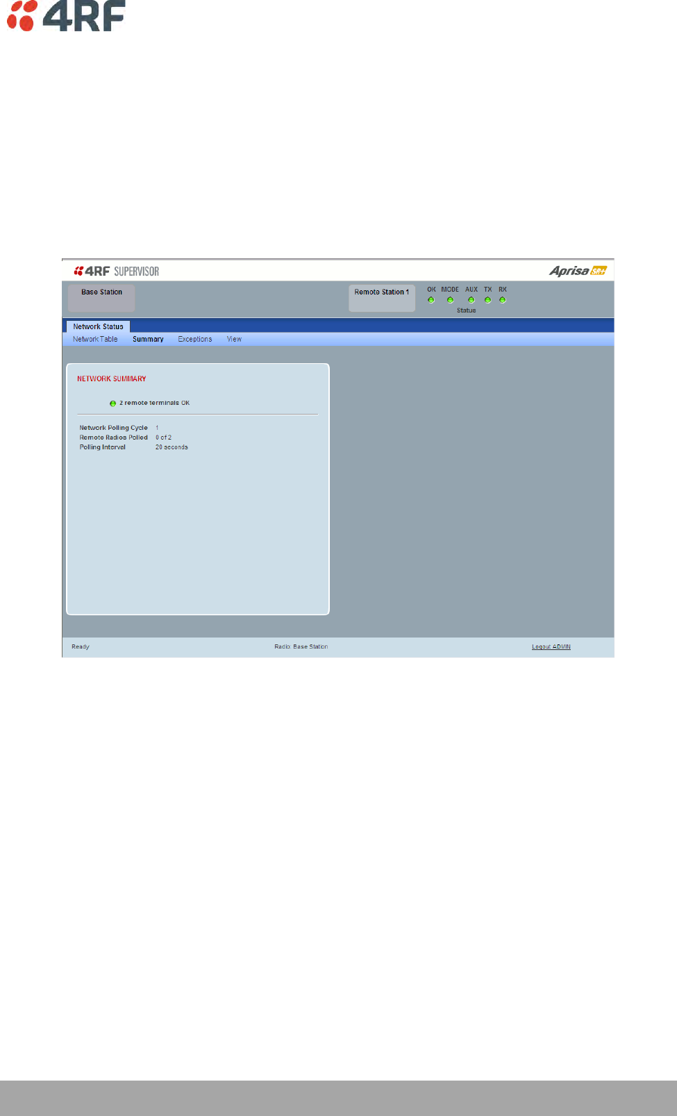
Managing the Radio | 247
Aprisa SRi User Manual 1.0.0
Network Status > Summary
Network View is an overview of the health of the network providing the ability to investigate issues
directly within SuperVisor.
This page provides an overall summary view of the alarm status of all registered remote stations for the
base station. When open, it provides a continuous monitor of the network.
Depending on the poll period set (20 seconds minimum) and the number of remotes in the network, it will
take at least three poll cycles to indicate a failure in the network. Initial results may indicate ‘All ok’ until
at least three poll cycles completed. This could take Number Of Remotes * Poll Period * 3 seconds to
complete.

248 | Managing the Radio
Aprisa SRi User Manual 1.0.0
NETWORK SUMMARY
A network poll will start when any of the Network Status pages are opened (Summary, Exceptions or
View). The network poll will only continue to poll the remote stations if one of the Network Status pages
is open (SuperVisor can lose PC focus). The network poll continues from where it was stopped last time it
was polling.
The initial result assumes that all remote stations are operating correctly.
Network Summary Example:
Result
Function
Network Polling Cycle
The number of poll cycles since first opening a Network Status >
Summary, Exceptions or View page.
The page example shows 6 polling cycles.
Remote Radios Polled
This shows the number of radios polled for the current polling
cycle out of the number remote radios registered with the base
station.
The page example shows 1 radio polled for the current polling
cycle out of 3 remote radios registered.
Polling Interval
The time interval between the completion of one radio poll and
the start of the next radio poll. To set the polling interval, see
‘Maintenance > General’ on page 185.
If a remote radio does not respond to a poll request within 10 seconds, the previous readings from that
radio will be presented. Connectivity to a remote radio will be show as ‘lost’ if the remote radio has not
responded to 3 consecutive poll requests.
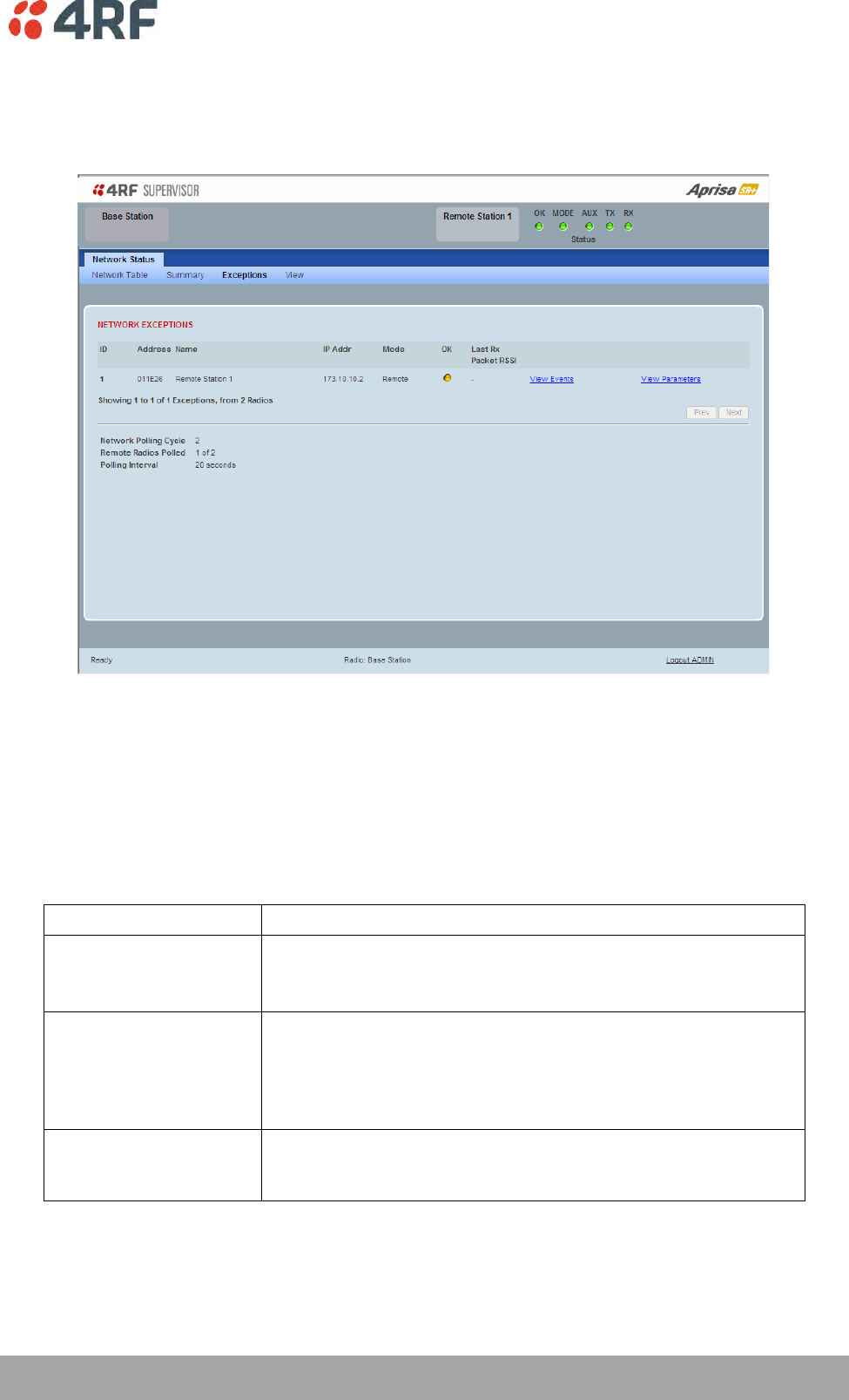
Managing the Radio | 249
Aprisa SRi User Manual 1.0.0
Network Status > Exceptions
This page provides a list of all registered remote radios that are in an alarmed state or have stopped
responding to the SuperVisor polling. When open, it provides a continuous monitor of the network.
NETWORK EXCEPTIONS
A network poll will start when any of the Network Status pages are opened (Summary, Exceptions or
View). The network poll will only continue to poll the remote stations if one of the Network Status pages
is open (SuperVisor can lose PC focus). The network poll continues from where it was stopped last time it
was polling.
Network Exceptions Example:
Result
Function
Network Polling Cycle
The number of poll cycles since first opening a Network Status >
Summary, Exceptions or View page.
The page example shows 4 polling cycles.
Remote Radios Polled
This shows the number of radios polled for the current polling
cycle out of the number remote radios registered with the base
station.
The page example shows 3 radios polled for the current polling
cycle out of 4 remote radios registered.
Polling Interval
The time interval between the completion of one radio poll and
the start of the next radio poll. To set the polling interval, see
‘Maintenance > General’ on page 185.

250 | Managing the Radio
Aprisa SRi User Manual 1.0.0
If a remote radio does not respond to a poll request within 10 seconds, the previous readings from that
radio will be presented. Connectivity to a remote radio will be show as ‘lost’ if the remote radio has not
responded to 3 consecutive poll requests.
If a remote radio on the list is detected to be responding to a poll request and no longer be in an alarmed
state, the entry for this remote radio will be removed from the list.
View Events
Clicking on View Events navigates to the Events page (see ‘Events’ on page 197) for the specific remote
radio where the radio events will be displayed.
View Parameters
Clicking on View Parameters navigates to the Monitoring page (see ‘Monitoring’ on page 227) for the
specific remote radio where the radio parameters will be displayed.
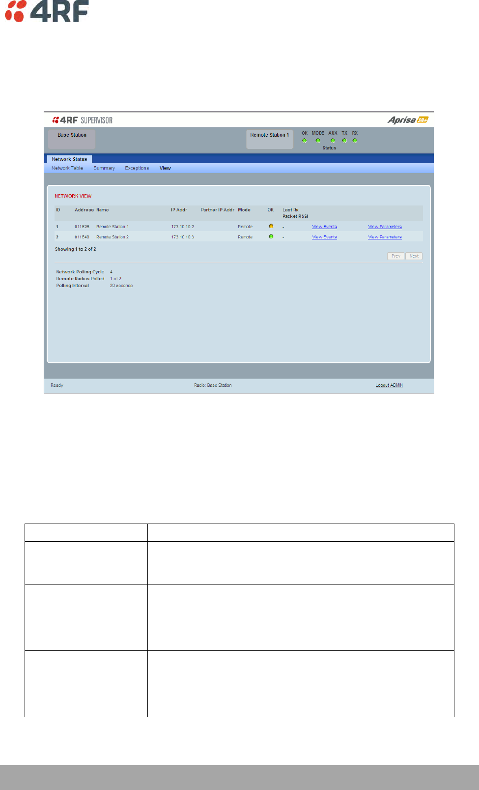
Managing the Radio | 251
Aprisa SRi User Manual 1.0.0
Network Status > View
This page provides a complete list of all registered remote radios. It is similar to the Exceptions page but
it shows all radios, not limited to the radios with alarms. When open, it provides a continuous monitor of
the network.
NETWORK VIEW
A network poll will start when any of the Network Status pages are opened (Summary, Exceptions or
View). The network poll will only continue to poll the remote stations if one of the Network Status pages
is open (SuperVisor can lose PC focus). The network poll continues from where it was stopped last time it
was polling.
Network View Example:
Result
Function
Network Polling Cycle
The number of poll cycles since first opening a Network Status >
Summary, Exceptions or View page.
The page example shows 2 polling cycles.
Remote Radios Polled
This shows the number of radios polled for the current polling
cycle out of the number remote radios registered with the base
station.
The page example shows 1 radio polled for the current polling
cycle out of 3 remote radios registered.
Polling Interval
The time interval between the completion of one radio poll and
the start of the next radio poll. To set the polling interval, see
‘Maintenance > General’ on page 185.
Note: as this polling feature utilizes air time, the polling interval
should be selected to suit the network traffic.

252 | Managing the Radio
Aprisa SRi User Manual 1.0.0
If a remote radio does not respond to a poll request within 10 seconds, the previous readings from that
radio will be presented. Connectivity to a remote radio will be show as ‘lost’ if the remote radio has not
responded to 3 consecutive poll requests.
View Events
Clicking on View Events navigates to the Events page (see ‘Events’ on page 197) for the specific remote
radio where the radio events will be displayed.
View Parameters
Clicking on View Parameters navigates to the Monitoring page (see ‘Monitoring’ on page 227) for the
specific remote radio where the radio parameters will be displayed.
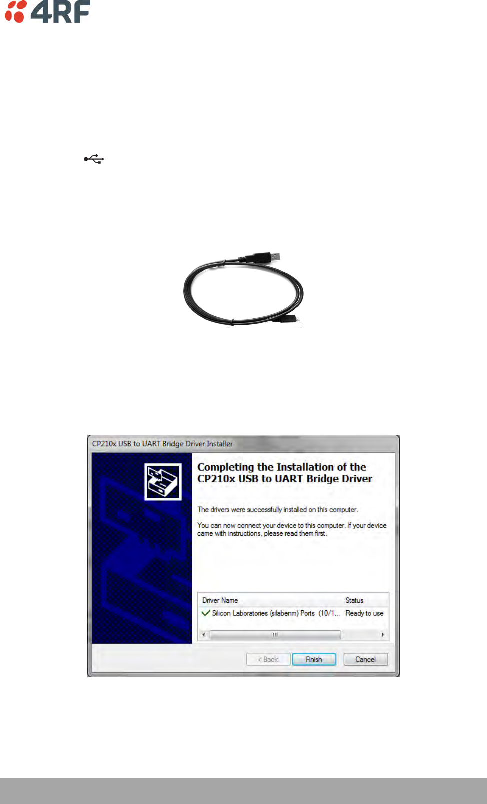
Managing the Radio | 253
Aprisa SRi User Manual 1.0.0
Command Line Interface
The Aprisa SRi has a Command Line Interface (CLI) which provides basic product setup and configuration.
This can be useful if you need to confirm the radio’s IP address, for example.
You can password-protect the Command Line Interface to prevent unauthorized users from modifying
radio settings.
This interface can be accessed via an Ethernet Port (RJ45), the Management Port (USB micro type B) or
the USB host port with a USB converter to RS-232 convertor.
Connecting to the Management Port
A USB Cable USB A to USB micro B, 1m is provided with each radio.
1. Connect the USB A to your computer USB port and the USB micro B to the management port of the
Aprisa SRi (MGMT).
2. Unzip the file ‘USB Serial Driver CP210x_VCP_Windows.zip’ to a temporary location and install the
appropriate driver on your computer. This file is on the Information and setup CD supplied with the
radio.
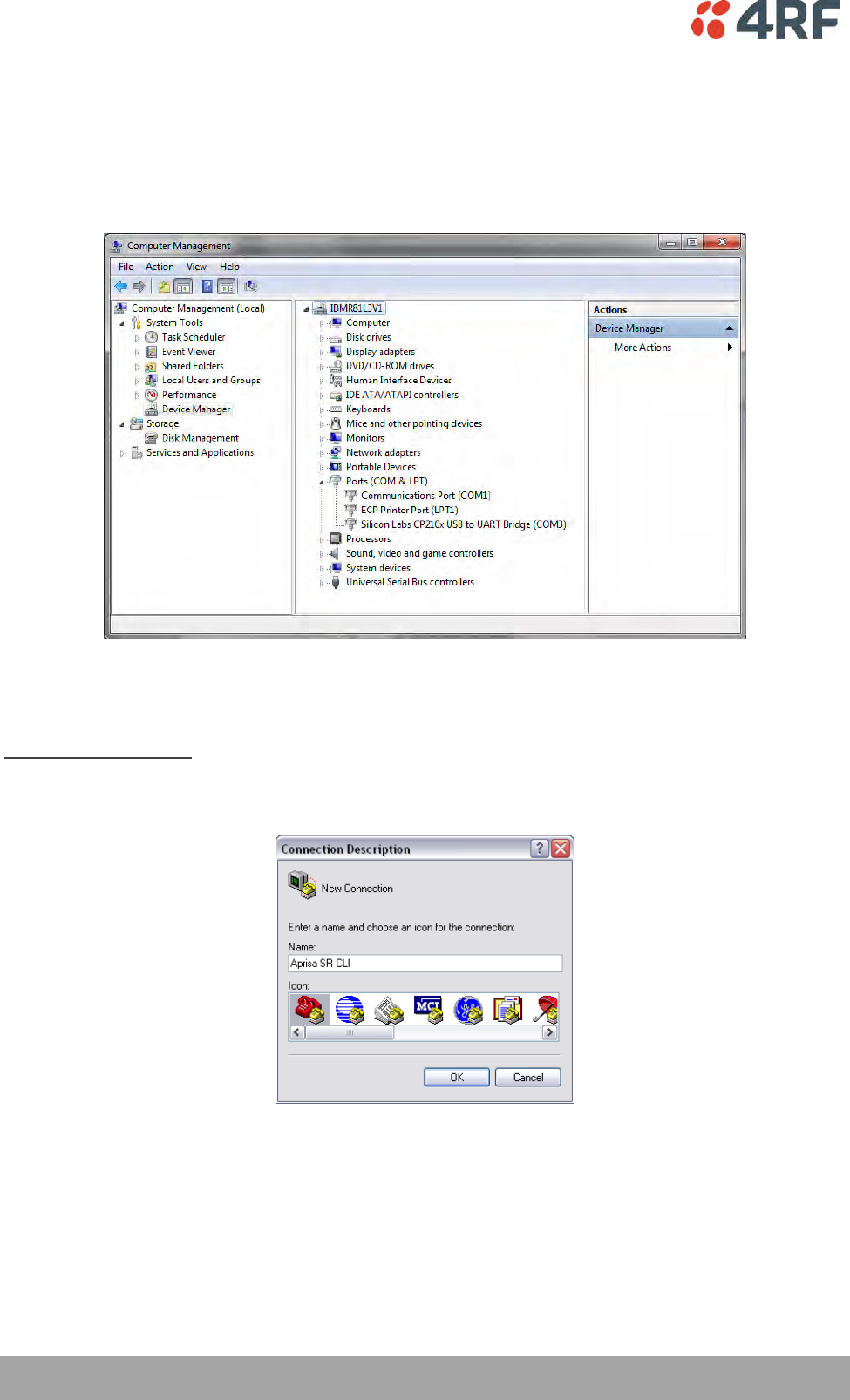
254 | Managing the Radio
Aprisa SRi User Manual 1.0.0
3. Go to your computer device manager (Win 7: Control Panel > Administrative Tools > Computer
Management > Device Manager)
4. Click on ‘Ports (COM & LPT)’
5. Make a note of the COM port which has been allocated to the ‘Silicon Labs CP210x USB to UART
Bridge’ (COM3 in the example below)
6. Open HyperTerminal or an alternative type of terminal Emulator program e.g. TeraTerm or Putty.
HyperTerminal Example
7. Enter a name for the connection (Aprisa SRi CLI for example) and click OK.
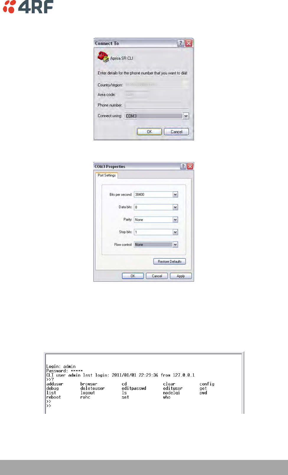
Managing the Radio | 255
Aprisa SRi User Manual 1.0.0
8. Select the COM port from the Connect Using drop-down box that was allocated to the UART USB.
9. Set the COM port settings as follows:
10. Click OK. The HyperTerminal window will open.
11. Press the Enter key to initiate the session.
12. Login to the Aprisa SRi CLI with a default Username ‘admin’ and Password ‘admin’.
The Aprisa SRi CLI menu is shown:
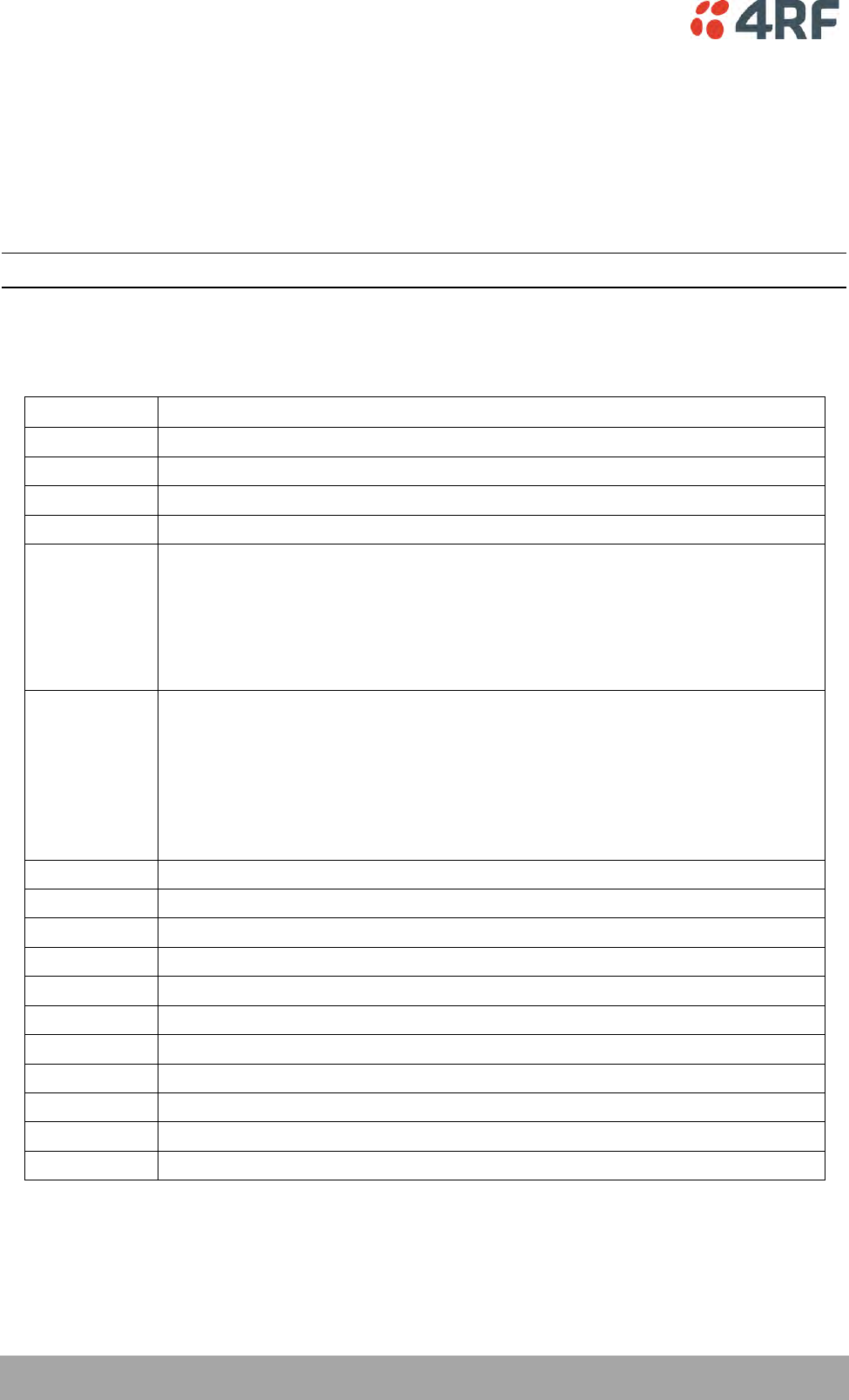
256 | Managing the Radio
Aprisa SRi User Manual 1.0.0
CLI Commands
To enter a CLI command:
1. Type the first few characters of the command and hit Tab. This auto completes the command.
2. Enter the command string and enter.
Note: All CLI commands are case sensitive.
The top level CLI command list is displayed by typing a ? at the command prompt.
The following is a list of the top level CLI commands and their usage:
CLI Command
Usage
adduser
adduser [-g <password aging>] [-a <account aging>] [-i <role>] <userName> <userPassword>
browser
browser <state(STR)>
cd
cd <changeMode(STR)>
clear
Clears the screen
config
config
userdefault
save
restore
factorydefault
restore
debug
set subsystem param(INT) level param(INT)
get
clear subsystem param(INT) level param(INT)
help
log
dump
clear
deleteuser
deleteuser <userName>
editpasswd
editpasswd <oldpassword> <newpassword>
edituser
edituser [-p <password>] [-g <password aging>] [-a <account aging>] [-i]
get
get [-m <mib name>] [-n <module name>] <attribute name> [indexes]
list
list <tablename>
logout
Logs out from the CLI
ls
Displays the next level menu items
pwd
Displays the current working directory
reboot
Reboots the radio
set
set [-m <mib name> ] [-n <module name>] <attribute name> <attribute set value> [indexes]
who
Shows the users currently logged into the radio
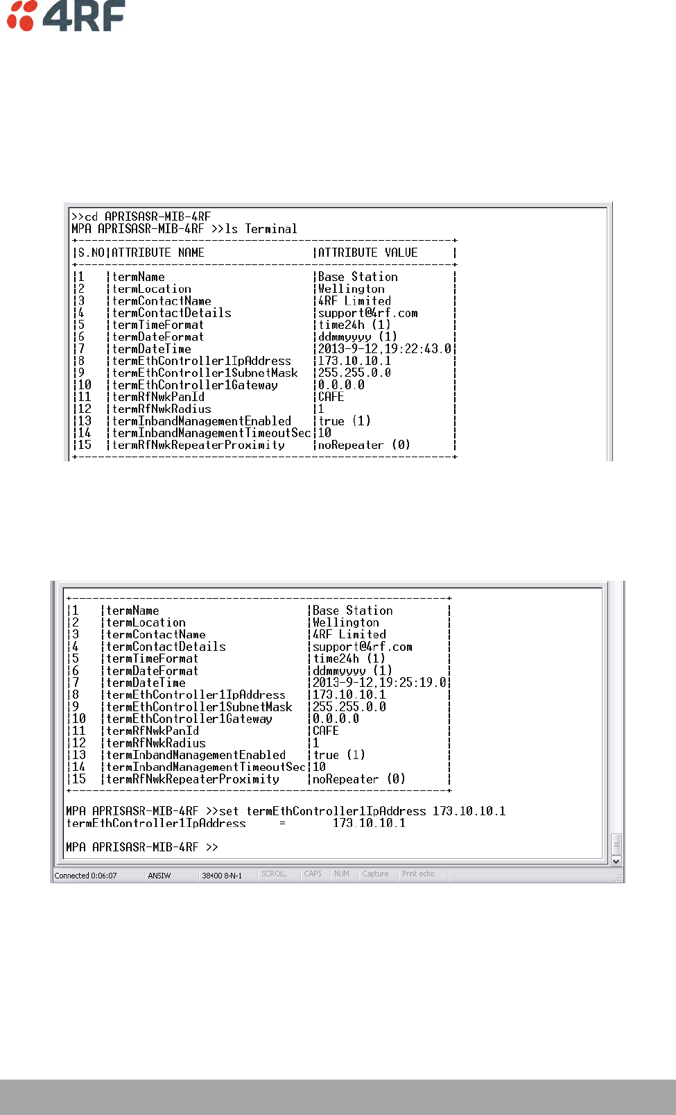
Managing the Radio | 257
Aprisa SRi User Manual 1.0.0
Viewing the CLI Terminal Summary
At the command prompt, type:
cd APRISASR-MIB-4RF
MPA APRISASR-MIB-4RF >>ls Terminal
Changing the Radio IP Address with the CLI
At the command prompt, type ‘set termEthController1IpAddress xxx.xxx.xxx.xxx’

258 | In-Service Commissioning
Aprisa SRi User Manual 1.0.0
8. In-Service Commissioning
Before You Start
When you have finished installing the hardware, RF and the traffic interface cabling, the system is ready
to be commissioned. Commissioning the radio is a simple process and consists of:
1. Powering up the radios.
2. Configuring all radios in the network using SuperVisor.
3. Aligning the antennas.
4. Testing that the links are operating correctly.
5. Connecting up the client or user interfaces.
What You Will Need
Appropriately qualified commissioning staff at both ends of each link.
Safety equipment appropriate for the antenna location at both ends of each link.
Communication equipment, that is, mobile phones or two-way radios.
SuperVisor software running on an appropriate laptop, computer, or workstation at the base
station radio.
Tools to facilitate loosening and re-tightening the antenna pan and tilt adjusters.
Predicted receiver input levels and fade margin figures from the radio link budget.

In-Service Commissioning | 259
Aprisa SRi User Manual 1.0.0
Antenna Alignment
A base station omni-directional collinear antenna has a vertical polarization. The remote station yagi
antennas must also have vertical polarization.
Aligning the Antennas
Align the remote station yagi antennas by making small adjustments while monitoring the RSSI. The Aprisa
SRi has a Test Mode which presents a real time visual display of the RSSI on the front panel LEDs. This can
be used to adjust the antenna for optimum signal strength (see ‘Test Mode’ on page 39).
Note: Low gain antennas need less adjustment in elevation as they are simply aimed at the horizon. They
should always be panned horizontally to find the peak signal.
1. Press and hold the TEST button on the radio LED panel until all the LEDs flash green (about 3 - 5
seconds).
Note: The time for the LEDs to display the RSSI result is variable, depending on the network traffic,
and can be up to 5 seconds. Small antenna adjustments should be made and then wait for the display
to refresh.
2. Move the antenna through a complete sweep horizontally (pan). Note down the RSSI reading for all the
peaks in RSSI that you discover in the pan.
3. Move the antenna to the position corresponding to the maximum RSSI value obtained during the pan.
Move the antenna horizontally slightly to each side of this maximum to find the two points where the
RSSI drops slightly.
4. Move the antenna halfway between these two points and tighten the clamp.
5. If the antenna has an elevation adjustment, move the antenna through a complete sweep (tilt)
vertically. Note down the RSSI reading for all the peaks in RSSI that you discover in the tilt.
6. Move the antenna to the position corresponding to the maximum RSSI value obtained during the tilt.
Move the antenna slightly up and then down from the maximum to find the two points where the RSSI
drops slightly.
7. Move the antenna halfway between these two points and tighten the clamp.
8. Recheck the pan (steps 2-4) and tighten all the clamps firmly.
9. To exit Test Mode, press and hold the TEST button until all the LEDs flash red (about 3 – 5 seconds).

260 | Product Options
Aprisa SRi User Manual 1.0.0
9. Product Options
Country Specific Products
The standard Aprisa SRi provides product option part numbers for the following country compliance
bodies;
APSI-N915-050-SO-21-C1AA
Country
Compliance Body
United States Of America
FCC
Canada
IC
APSI-N915-050-SO-21-C2AA
Country
Compliance Body
Australia
ACMA
New Zealand
R-NZ
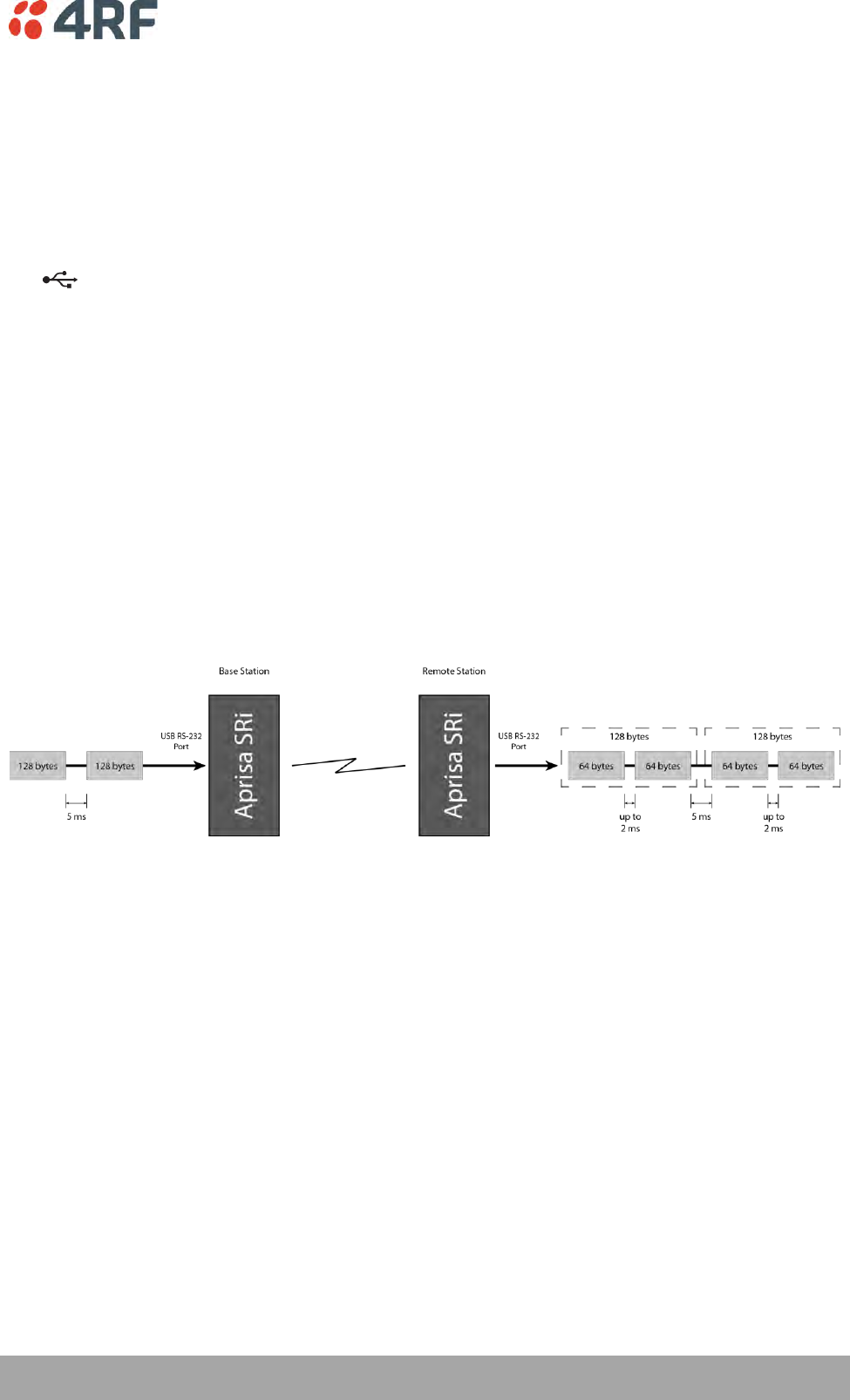
Product Options | 261
Aprisa SRi User Manual 1.0.0
USB Serial Ports
USB RS-232 / RS-485 Serial Port
The Aprisa SRi USB host port is predominantly used for software upgrade and diagnostic reporting.
However, it can also be used to provide an additional RS-232 DCE or RS-485 serial port for customer
traffic.
This is accomplished with a USB to RS-232 / RS-485 serial converter cable. This plugs into the USB host
port connector and can be terminated with the required customer connector.
This additional RS-232 / RS-485serial port is enabled with the SuperVisor mode setting in Serial Port
Settings (see ‘Serial > Port Setup’ on page 108).
The Aprisa SRi USB port has driver support for these USB serial converters. Other USB serial converters
may not operate correctly.
USB RS-232 / RS-485 operation
The USB serial converter buffers the received data frames into 64 byte blocks separated by a small inter-
frame gap.
For the majority of applications, this fragmentation of egress frames is not an issue. However, there are
some applications that may be sensitive to the inter-frame gap, therefore, these applications need
consideration.
A 5 ms inter-frame is recommended for the applications that are sensitive to inter-frame gap timings.
On a USB RS-232 port, Modbus RTU can operate up to 9600 bit/s with all packet sizes and up to 115200
bit/s if the packet size is less than 64 bytes. The standard RS-232 port is fully compatible with Modbus RTU
at all baud rates.
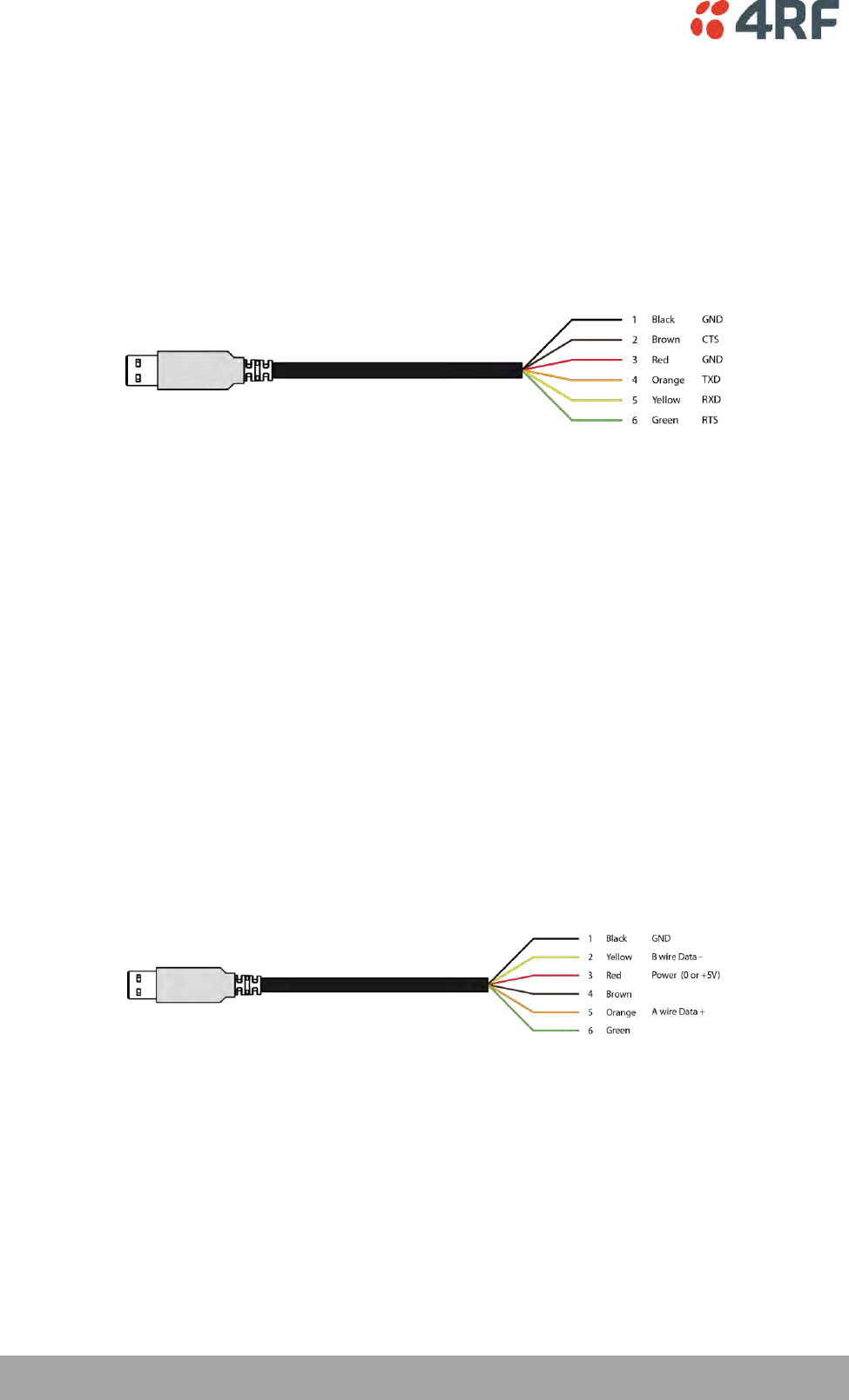
262 | Product Options
Aprisa SRi User Manual 1.0.0
USB RS-232 Cabling Options
The following converter cables are available as Aprisa SRi accessories to provide the customer interface.
The kit contains a USB connector retention clip (see ‘USB Retention Clip’ on page 263).
1. USB Converter to 1.8 metre multi-strand cable 6 wire for termination of customer connector
Part Number
Part Description
APSB-KFCA-USB-23-MS-18
4RF SRi Acc, Kit, Interface, USB Conv, RS-232, Multi-strand, 1.8m
2. USB converter to RJ45 female kit for USB to RS-232 DCE conversion.
Part Number
Part Description
APSB-KFCA-USB-23-45-MF18
4RF SRi Acc, Kit, Interface, USB Conv, RS-232, RJ45, Female, 1.8m
3. USB converter to DB9 female kit for USB to RS-232 DCE conversion.
Part Number
Part Description
APSB-KFCA-USB-23-D9-MF18
4RF SRi Acc, Kit, Interface, USB Conv, RS-232, DB9, Female, 1.8m
USB RS-485 Cabling Options
The following converter cable is available as an Aprisa SRi accessory to provide the customer interface RS-
485 2 wire. The kit contains a USB connector retention clip (see ‘USB Retention Clip’ on page 263).
1. USB Converter to 1.8 metre multi-strand cable 6 wire for termination of customer interface
Part Number
Part Description
APSB-KFCA-USB-48-MS-18
4RF SRi Acc, Kit, Interface, USB Conv, RS-485, Multi-strand, 1.8m
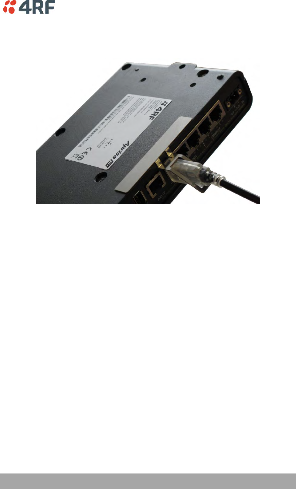
Product Options | 263
Aprisa SRi User Manual 1.0.0
USB Retention Clip
The USB Retention Clip attaches to the underside of the Aprisa SRi enclosure adjacent to the USB
connector.
To attach the USB Retention Clip:
1. Clean the enclosure surface where the retention clip will attach with an alcohol based cleaner e.g.
Isopropanol.
2. Peel off the retention clip protective backing.
3. Stick the clip onto the Aprisa SRi enclosure ensuring that it aligns to the middle of the radio USB
connector.

Maintenance | 265
Aprisa SRi User Manual 1.0.0
10. Maintenance
No User-Serviceable Components
Except for fuse replacement, there are no user-serviceable components within the radio.
All hardware maintenance must be completed by 4RF or an authorized service centre.
Do not attempt to carry out repairs to any boards or parts.
Return all faulty radios to 4RF or an authorized service centre.
For more information on maintenance and training, please contact 4RF Customer Services at
support@4rf.com.
CAUTION: Electro Static Discharge (ESD) can damage or destroy the sensitive electrical components in the
radio.

266 | Maintenance
Aprisa SRi User Manual 1.0.0
Software Upgrade
A software upgrade can be performed on a single Aprisa SRi radio or an entire Aprisa SRi network.
Network Software Upgrade
This process allows customers to upgrade their Aprisa SRi network from the central base station location
without need for visiting remote sites.
The Software Pack is loaded into the base station with the file transfer process (see ‘Software > File
Transfer’ on page 212) and distributed via the radio link to all remote stations.
When all remote stations receive the Software Pack version, the software can be remotely activated on all
remote stations.
To upgrade the entire Aprisa SRi network software:
1. Using File Transfer, load the software pack into the base station (see ‘Software > File Transfer’ on
page 212). The software can be transferred to the radio via an FTP transfer or from a USB flash drive.
The Aprisa SRi network file transfer operation is indicated in base station and remote stations by a
flashing orange AUX LED.
2. Distribute the software to the entire network of remote radios (see ‘Software > Remote Distribution’
on page 220). Note that the distribution process over the air will take some time, depending on RF
and Transfer rate settings.
The Aprisa SRi network software distribution operation is indicated in base station and remote stations
by a flashing orange MODE LED.
Note: The distribution of software to remote stations does not stop customer traffic from being
transferred. However, due to the volume of traffic, the software distribution process may affect
customer traffic.
Software distribution traffic is classified as ‘management traffic’ but does not use the Ethernet
management priority setting. Software distribution traffic priority has a fixed priority setting of ‘very
low’.
3. Activate the software on the entire network of remote radios (see ‘Software > Remote Activation’ on
page 222).
Note: When the new software activates on the remote radios, all link communication from the base
station to the remote will be lost. The base station will attempt to re-establish connectivity to the
remote radios for the new version verification but this will fail. However, when the new software
activates on the remote radios, the remote radio will reboot automatically and link communication
will restore when the base station software is activated.
When the Remote Activation process gets to the ‘Remote Radios On New Version’ step, don’t wait for
this to complete but proceed to step 4.
4. Activate the software on the base station radio (see ‘Software > Manager’ on page 216).
5. When the new software has been activated, remote stations will re-register with the base station. The
remote stations software version can verified with ‘Network Status > Network Table’ on page 246.
6. When the base station restarts with the new software, rediscover the nodes (see ‘Discover Nodes’ on
page 193).

Maintenance | 267
Aprisa SRi User Manual 1.0.0
7. Check that all remote radios are now running on the new software (see ‘Network Status > Network
Table’ on page 246).
Note: The following steps will only be necessary if for some reason steps 1-7 did not operate correctly
or if software activation is attempted before the distribution process ends or the remote radio was off
during steps 1-7 and turns on later. Thus, the following steps will most likely not be required.
8. If step 7 shows that not all remote radios are running the latest software version, restore the base /
master station to the previous software version (see ‘Software > Manager’ on page 216).
9. Attempt to re-establish connectivity to the remote radios that have failed to upgrade by navigating to
and remotely managing the remote radios individually.
10. Navigate to the remote radio history log and review the logs to determine the reason for the failure to
activate the new software version.
11. Take appropriate actions to address the reported issue. If connectivity restores with the failed
remotes, repeat steps 2-7 if required.

268 | Maintenance
Aprisa SRi User Manual 1.0.0
Single Radio Software Upgrade
This upgrade process is for upgrading the software on a single Aprisa SRi radio.
File Transfer Method
The Software Pack is loaded into the radio with the file transfer process (see ‘Software > File Transfer’ on
page 212) and activated (see ‘Software > Manager’ on page 216).
The Aprisa SRi upgrade operation is indicated by a flashing orange AUX LED.
To upgrade the Aprisa SRi radio software:
1. Unzip the software release files in to the root directory of a USB flash drive.
2. Insert the USB flash drive into the host port .
3. Using File Transfer, load the software pack into the radio (see ‘Software > File Transfer’ on page 212).
4. Remove the USB flash drive from the host port .
5. Activate the software on the radio (see ‘Software > Manager’ on page 216).

Maintenance | 269
Aprisa SRi User Manual 1.0.0
USB Boot Upgrade Method
A single Aprisa SRi radio can also be upgraded simply by plugging a USB flash drive containing the new
software into the USB A host port on the Aprisa SRi front panel and power cycling the radio.
To upgrade the Aprisa SRi radio software:
1. Unzip the software release files in to the root directory of a USB flash drive.
2. Check that the SuperVisor USB Boot Upgrade setting is set to ‘Load and Activate’ (see ‘Software >
Setup’ on page 211).
3. Power off the Aprisa SRi and insert the USB flash drive into the host port .
4. Power on the Aprisa SRi.
5. The software upgrade process is complete when the OK LED flashes green. This can take about 2
minutes.
The software will have loaded in to the radio current software version.
6. Remove the USB flash drive from the host port .
7. Power cycle the Aprisa SR.
Login to the radio being upgraded and go to SuperVisor ‘Software > Manager’ on page 216.
The version of the uploaded software will be displayed in the Software Pack ‘Version’ field and the
current software version.
If the upgrade process did not start, the Aprisa SRi could already be operating on the version of software
on the USB flash drive. This will be indicated by flashing OK LED and then the OK, MODE and AUX will light
steady green.
If the radio is not operating on the new software (after the power cycle), it could be caused by the
SuperVisor ‘USB Boot Upgrade’ setting set to ‘Load Only’ (see ‘Software > Setup’ on page 211).
In this case, go to SuperVisor see ‘Software > Manager’ on page 216 and tick the Software Pack ‘Activate’
checkbox and click ‘Apply’.
If any Display Panel LED flashes red or is steady red during the upgrade process, it indicates that the
upgrade has failed. This could be caused by incorrect files on the USB flash drive or a radio hardware
failure.
Software Downgrade
Radio software can also be downgraded if required. This may be required if a new radio is purchased for
an existing network which is operating on an earlier software release.
The downgrade process is the same as the upgrade process.
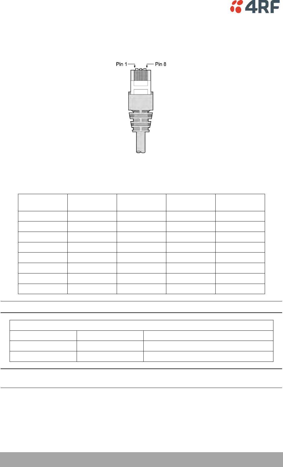
270 | Interface Connections
Aprisa SRi User Manual 1.0.0
11. Interface Connections
RJ45 Connector Pin Assignments
RJ45 pin numbering
Ethernet Interface Connections
Pin Number
Pin Function
Direction
TIA-568A Wire
Colour
TIA-568B Wire
Colour
1
Transmit
Output
Green/white
Orange/white
2
Transmit
Output
Green
Orange
3
Receive
Input
Orange/white
Green/white
4
Not used
Blue
Blue
5
Not used
Blue/white
Blue/white
6
Receive
Input
Orange
Green
7
Not used
Brown/white
Brown/white
8
Not used
Brown
Brown
Note: The TIA-568B wiring is the most commonly used and matches the cables we supply.
RJ45 connector LED indicators
LED
Status
Explanation
Green
On
Ethernet signal received
Orange
Flashing
Data traffic present on the interface
Note: Do not connect Power over Ethernet (PoE) connections to the Aprisa SRi Ethernet ports as this will
damage the port.

Interface Connections | 271
Aprisa SRi User Manual 1.0.0
RS-232 Serial Interface Connections
RS-232 Pinout
The Aprisa RS-232 Serial Interface is always configured as a DCE:
RJ45
Pin Number
Pin Function
Direction
TIA-568A Wire
Colour
TIA-568B Wire
Colour
1
RTS
Input
Green / white
Orange/white
2
DTR
Input
Green
Orange
3
TXD
Input
Orange / white
Green/white
4
Ground
Blue
Blue
5
DCD
Output
Blue / white
Blue/white
6
RXD
Output
Orange
Green
7
DSR
Output
Brown / white
Brown/white
8
CTS
Output
Brown
Brown
Note: The TIA-568B wiring is the most commonly used and matches the cables we supply.
RS-232 Customer Cable Wiring
Aprisa RS-232 Interface - DCE
DTE Customer Interface
DCE Customer Interface
RJ45
Pin Number
Pin
Function
Direction
Pin
Function
DB9 Male
Pinout
Pin
Function
DB9 Female
Pinout
1
RTS
Input
RTS
7
CTS
8
2
DTR / Sleep
Mode
Input
DTR
4
DSR
6
3
TXD
Input
TXD
3
RXD
2
4
Ground
Ground
5
Ground
5
5
DCD
Output
DCD
1
6
RXD
Output
RXD
2
TXD
3
7
DSR
Output
DSR
6
DTR
4
8
CTS
Output
CTS
8
RTS
7
RS-232 RJ45 LED Indicators
LED
Status
Explanation
Green
On
RS-232 device connected
Orange
Flashing
Data present on the interface

272 | Interface Connections
Aprisa SRi User Manual 1.0.0
Alarm Interface Connections
RJ45
Pin Number
Pin Function
Direction
TIA-568A Wire
Colour
TIA-568B Wire
Colour
1
Alarm 1 Input
Input
Green / white
Orange/white
2
Ground
Green
Orange
3
Alarm 2 Input
Input
Orange / white
Green/white
4
Ground
Blue
Blue
5
Alarm 1 Output
/ Sleep Mode
Output
Blue / white
Blue/white
6
Ground
Orange
Green
7
Alarm 2 Output
Output
Brown / white
Brown/white
8
Ground
Brown
Brown
Note: The TIA-568B wiring is the most commonly used and matches the cables we supply.

Alarm Types and Sources | 273
Aprisa SRi User Manual 1.0.0
12. Alarm Types and Sources
Alarm Types
There are three types of alarm event configuration types:
1. Threshold Type
These alarm events have lower and upper limits. An alarm is raised if current reading is outside the limits.
Note: the limits for PA Current, TX AGC, TX Reverse Power and Thermal shutdown are not user
configurable.
2. Error Ratio Type
This is the ratio of bad packets vs total packets in the defined sample duration.
For Serial, it is the ratio of bad characters vs total characters in the duration seconds. An alarm is raised if
current error ratio is greater than the configured ratio. The error ratio is configured in ‘Upper Limit’ field
and accepts value between 0 and 1. Monitoring of these events can be disabled by setting the duration
parameter to 0.
3. Sample Duration Type
Used for No Receive data events type. An alarm is raised if no data is received in the defined sample
duration. Monitoring of these events can be disabled by setting the duration parameter to 0.
See ‘Events > Events Setup’ on page 199 for setup of alarm thresholds / sample durations etc.

274 | Alarm Types and Sources
Aprisa SRi User Manual 1.0.0
Alarm Events
Transmitter Alarm Events
Event
ID
Event Display
Text
Default
Severity
Configuration
Type
Function
Recommended Actions
1
PA Current
critical(1)
Threshold Type
Alarm to indicate that the
current drawn by the
transmitter power amplifier
is outside defined limits.
Check antenna is not open or
shorted, check duplexer
correctly connected and
tuned, if OK replace radio.
61
PA Driver Current
critical(1)
Threshold Type
Alarm to indicate that the
current drawn by the
transmitter power amplifier
driver is outside defined
limits.
Check antenna is not open or
shorted, check duplexer
correctly connected and
tuned, if OK replace radio.
62
PA Stability
warning(4)
Threshold Type
Alarm to indicate that the
power amplifier is oscillating
which may cause corruption
of the TX signal
Check antenna is not open or
shorted, check duplexer
correctly connected and
tuned, if OK replace radio.
2
TX AGC
critical(1)
Threshold Type
Alarm to indicate that the
variable gain control of the
transmitter is outside
defined limits.
Check antenna is not open or
shorted, check duplexer
correctly connected and
tuned, if OK replace radio.
3
TX Reverse Power
warning(4)
Threshold Type
Alarm to indicate that the
antenna is not connected to
the radio
Check antenna is not open or
shorted, check duplexer
correctly connected and
tuned, and confirm VSWR at
TX port is less than 2:1. If
OK replace radio.
60
TX Forward
Power
warning(4)
Threshold Type
Alarm to indicate that the
transmitter power is outside
the selected TX power
setting.
Check antenna is not open or
shorted, check duplexer
correctly connected and
tuned, and confirm VSWR at
TX port is less than 2:1. If
OK replace radio.
4
Temperature
Threshold
warning(4)
Threshold Type
Alarm to indicate that the
transmitter temperature is
outside defined limits.
Check ambient temperature
and for airflow obstructions.
5
TX Synthesizer
Not Locked
critical(1)
Threshold Type
Alarm to indicate that the
transmitter synthesizer is not
locked.
Power off radio and restart.
If condition persists replace
radio.
31
Thermal
Shutdown
critical(1)
Threshold Type
Alarm to indicate that the
transmitter has shutdown
due to excessively high
temperature.
Check ambient temperature
and for airflow obstructions.
Receiver Alarm Events
Event
ID
Event Display
Text
Default
Severity
Configuration
Type
Function
Recommended Actions
7
RSSI Threshold
warning(4)
Threshold Type
Alarm to indicate that the
receiver RSSI reading taken
on the last packet received is
outside defined limits.
Check antenna is not open or
shorted. If the antenna is
directional check for off-
pointing.
8
RX Synthesizer
Not Locked
critical(1)
Not Configurable
Alarm to indicate that the
receiver Synthesizer is not
locked on the RF received
signal.
Power off radio and restart.
If condition persists replace
radio.
9
RX CRC Errors
warning(4)
Error Ratio Type
Alarm to indicate that the
data received on the RF path
contains errors at a higher
rate than the defined error
rate threshold.
Check antenna is not open or
shorted. Check duplexer is
correctly tuned. If the
antenna is directional check
for off-pointing. Power off
radio and restart. If
condition persists replace
radio.

Alarm Types and Sources | 275
Aprisa SRi User Manual 1.0.0
Radio Interface Path Alarm Events
Event
ID
Event Display
Text
Default
Severity
Configuration
Type
Function
Recommended Actions
34
RF No Receive
Data
warning(4)
Sample Duration
Type
Alarm to indicate that there
is no data received on the RF
path in the defined duration
period.
Check master is operational.
If new deployment check set-
up, frequencies, and
duplexer (if used). Check
antenna is not open or
shorted. If the antenna is
directional check for off-
pointing. Power off radio
and restart. If condition
persists replace radio.
Modem Alarm Events
Event
ID
Event Display
Text
Default
Severity
Configuration
Type
Function
Recommended Actions
68
Modem FEC
disable
warning(4)
Not Configurable
Alarm to indicate that FEC
has been disabled. This could
be a permanent event or a
timed event.
Alarm to indicate that FEC
has been disabled. This could
be a permanent event or a
timed event.
70
Modem ACM
locked
warning(4)
Not Configurable
Alarm to indicate that the
ACM has been locked to a
fixed coding and modulation.
This could be a permanent
event or a timed event.
Alarm to indicate that the
ACM has been locked to a
fixed coding and modulation.
This could be a permanent
event or a timed event.
Customer Equipment Interface Path Alarm Events
Event
ID
Event Display
Text
Default
Severity
Configuration
Type
Function
Recommended Actions
10
Port 1 Eth No
Receive Data
warning(4)
Sample Duration
Type
Alarm to indicate that
Ethernet port 1 has no
received input signal in the
defined duration period.
Check Ethernet cable and
connector. Check switch
port or RTU is active. Check
IP and VLAN configuration.
11
Port 1 Eth Data
Receive Errors
warning(4)
Error Ratio Type
Alarm to indicate that
Ethernet port 1 received
input signal contains errors
at a higher rate than the
defined error rate threshold.
Check Ethernet cable and
connector. Check switch
port or RTU is active. Check
IP and VLAN configuration.
12
Port 1 Eth Data
Transmit Errors
warning(4)
Error Ratio Type
Alarm to indicate that
Ethernet port 1 transmitted
output signal contains errors
at a higher rate than the
defined error rate threshold.
Check Ethernet cable and
connector. Check switch
port or RTU is active. Check
IP and VLAN configuration.
35
Port 2 Eth No
Receive Data
warning(4)
Sample Duration
Type
Alarm to indicate that
Ethernet port 2 has no
received input signal in the
defined duration period.
Check Ethernet cable and
connector. Check switch
port or RTU is active. Check
IP and VLAN configuration.
36
Port 2 Eth Data
Receive Errors
warning(4)
Error Ratio Type
Alarm to indicate that
Ethernet port 2 received
input signal contains errors
at a higher rate than the
defined error rate threshold.
Check Ethernet cable and
connector. Check switch
port or RTU is active. Check
IP and VLAN configuration.
37
Port 2 Eth Data
Transmit Errors
warning(4)
Error Ratio Type
Alarm to indicate that
Ethernet port 2 transmitted
output signal contains errors
at a higher rate than the
defined error rate threshold.
Check Ethernet cable and
connector. Check switch
port or RTU is active. Check
IP and VLAN configuration.
44
Port 3 Eth No
Receive Data
warning(4)
Sample Duration
Type
Alarm to indicate that
Ethernet port 3 has no
received input signal in the
defined duration period.
Check Ethernet cable and
connector. Check switch
port or RTU is active. Check
IP and VLAN configuration.

276 | Alarm Types and Sources
Aprisa SRi User Manual 1.0.0
Event
ID
Event Display
Text
Default
Severity
Configuration
Type
Function
Recommended Actions
45
Port 3 Eth Data
Receive Errors
warning(4)
Error Ratio Type
Alarm to indicate that
Ethernet port 3 received
input signal contains errors
at a higher rate than the
defined error rate threshold.
Check Ethernet cable and
connector. Check switch
port or RTU is active. Check
IP and VLAN configuration.
46
Port 3 Eth Data
Transmit Errors
warning(4)
Error Ratio Type
Alarm to indicate that
Ethernet port 3 transmitted
output signal contains errors
at a higher rate than the
defined error rate threshold.
Check Ethernet cable and
connector. Check switch
port or RTU is active. Check
IP and VLAN configuration.
48
Port 4 Eth No
Receive Data
warning(4)
Sample Duration
Type
Alarm to indicate that
Ethernet port 4 has no
received input signal in the
defined duration period.
Check Ethernet cable and
connector. Check switch
port or RTU is active. Check
IP and VLAN configuration.
49
Port 4 Eth Data
Receive Errors
warning(4)
Error Ratio Type
Alarm to indicate that
Ethernet port 4 received
input signal contains errors
at a higher rate than the
defined error rate threshold.
Check Ethernet cable and
connector. Check switch
port or RTU is active. Check
IP and VLAN configuration.
50
Port 4 Eth Data
Transmit Errors
warning(4)
Error Ratio Type
Alarm to indicate that
Ethernet port 4 transmitted
output signal contains errors
at a higher rate than the
defined error rate threshold.
Check Ethernet cable and
connector. Check switch
port or RTU is active. Check
IP and VLAN configuration.
13
Port 1 Serial Data
No Receive Data
warning(4)
Sample Duration
Type
Alarm to indicate that the
RS-232 port 1 has no received
input signal in the defined
duration period.
Check serial ports settings,
check serial cable and
connector.
14
Port 1 Serial Data
Receive Errors
warning(4)
Error Ratio Type
Alarm to indicate that the
RS-232 port 1 received input
signal contains errors at a
higher rate than the defined
error rate threshold.
Check serial ports settings,
check serial cable and
connector.
52
Port 2 Serial Data
No Receive Data
warning(4)
Sample Duration
Type
Alarm to indicate that the
RS-232 port 2 has no received
input signal in the defined
duration period.
Check serial ports settings,
check serial cable and
connector.
53
Port 2 Serial Data
Receive Errors
warning(4)
Error Ratio Type
Alarm to indicate that the
RS-232 port 2 received input
signal contains errors at a
higher rate than the defined
error rate threshold.
Check serial ports settings,
check serial cable and
connector.
63
USB Port Serial
Data No Receive
Data
warning(4)
Sample Duration
Type
Alarm to indicate that the
USB port has no received
input signal in the defined
duration period.
Check serial ports settings,
check USB serial cable and
adapter, check serial
connector.
64
USB Port Serial
Data Receive
Errors
warning(4)
Error Ratio Type
Alarm to indicate that the
USB port received input
signal contains errors at a
higher rate than the defined
error rate threshold.
Check serial ports settings,
check USB serial cable and
adapter, check serial
connector.
Component Failure Alarm Events
Event
ID
Event Display
Text
Default
Severity
Configuration
Type
Function
Recommended Actions
16
Component
Failure
major(2)
Not Configurable
Alarm to indicate that a
hardware component has
failed.
Power off and restart radio.
If fault persists replace
radio.

Alarm Types and Sources | 277
Aprisa SRi User Manual 1.0.0
Hardware Alarm Events
Event
ID
Event Display
Text
Default
Severity
Configuration
Type
Function
Recommended Actions
56
VDC Power
Supply
warning(4)
Not Configurable
Alarm to indicate that the
input power source is outside
the operating limits of 10 to
30 VDC
Check DC connection to
radio. Replace power supply.
57
3.3 Volts Power
Supply
warning(4)
Not Configurable
Alarm to indicate that the
3.3 volt power rail is outside
defined limits.
Power off and restart radio.
If fault persists replace
radio.
58
5.0 Volts Power
Supply
warning(4)
Not Configurable
Alarm to indicate that the
5.0 volt power rail is outside
defined limits.
Power off and restart radio.
If fault persists replace
radio.
59
7.2 Volts Power
Supply
warning(4)
Not Configurable
Alarm to indicate that the
7.2 volt power rail is outside
defined limits.
Power off and restart radio.
If fault persists replace
radio.
71
15 Volts Power
Supply
warning(4)
Not Configurable
Alarm to indicate that the 15
volt power rail is outside
defined limits.
Power off and restart radio.
If fault persists replace
radio.
Software Alarm Events
Event
ID
Event Display
Text
Default
Severity
Configuration
Type
Function
Recommended Actions
20
Calibration
Failure
major(2)
Not Configurable
Alarm to indicate that the RF
calibration has failed.
Power off and restart radio.
If fault persists replace
radio.
21
Configuration Not
Supported
major(2)
Not Configurable
Alarm to indicate that a
configuration has entered
that is invalid.
Restore previous
configuration, remove out of
range or invalid parameters,
updated software.
32
Network
Configuration
Warning
warning(4)
Not Configurable
Alarm to indicate a network
configuration problem e.g.
remote not registered.
Check for invalid parameters.
Audit network settings.
73
Radio Network
warning(4)
Not Configurable
Alarm to indicate that there
is an alarm in the radio
network e.g. a remote radio
has not registered or
duplicate IP address.
Check for duplicate or invalid
parameters. Audit network
settings.
39
Software Restart
Required
warning(4)
Not Configurable
Alarm to indicate that a
configuration has changed
that requires a software
reboot.
Reboot radio.
Hardware Alarm Input Alarm Events
Event
ID
Event Display
Text
Default
Severity
Configuration
Type
Function
Recommended Actions
24
Alarm Input 1
warning(4)
Not Configurable
Alarm to indicate that there
is an active alarm on
hardware alarm input 1
Action depends on nature of
third-party alarm.
25
Alarm Input 2
warning(4)
Not Configurable
Alarm to indicate that there
is an active alarm on
hardware alarm input 2
Action depends on nature of
third-party alarm.

278 | Alarm Types and Sources
Aprisa SRi User Manual 1.0.0
Informational Events
Event
ID
Event Display
Text
Default
Severity
Function
Recommended Actions
26
User
authentication
succeeded
information
(5)
Event to indicate that a user is
successfully authenticated on the radio
during login. The information on the
user that was successfully
authenticated is provided in the
eventHistoryInfo object of the Event
History Log.
Information
No action required unless unexpected
27
User
authentication
failed
information
(5)
Event to indicate that a user has failed
to be authenticated on the radio during
login. The information on the user that
was unsuccessfully authenticated is
provided in the eventHistoryInfo object
of the Event History Log.
Check for possible intrusion attempt.
If unexpected follow cyber incident
report procedure.
28
Protection switch
failed
information
(5)
Event to indicate that a protection
switch-over cannot occur for some
reason. The reason for the failure to
switch is described in the
eventHistoryInfo object of the Event
History Log.
Investigate reason for switch over and
take remedial action.
29
Software System
Check
information
(5)
Event to indicate that the software has
done a system check on the radio. Any
information relevant to the cause of the
event is provided in the
eventHistoryInfo object of the Event
History Log.
Information
No action required unless unexpected
30
Software Start Up
information
(5)
Event to indicate that the radio
software has started. Any information
relevant to the software start up is
provided in the eventHistoryInfo object
of the Event History Log.
Information
No action required unless unexpected
33
Protection Switch
Occurred
information
(5)
Event to indicate that a protection
switch-over occurs for some reason.
The reason for the switch-over is
described in the eventHistoryInfo
object of the Event History Log.
Investigate reason for switch over and
take remedial action.
41
File Transfer
Activity
information
(5)
Event to indicate that a data file is
being transferred to or from the radio.
Information
No action required unless unexpected
42
Software
Management
Activity
information
(5)
Event to indicate that software is being
distributed to remote radios.
Information
No action required unless unexpected
43
Terminal Server
TCP Activity
information
(5)
Event to indicate TCP packets are being
transferred from the terminal server.
Information
No action required unless unexpected
55
Terminal Unit
Information
information
(5)
Event to indicate a miscellaneous
activity occurring on the radio
Information no action required unless
unexpected.
65
Event Action
Activity
information
(5)
Event to indicate an event action
occurring on the radio
Information
No action required unless unexpected
72
User SuperVisor
Session Logout
information
(5)
Event to indicate that a user has logged
out or the user session has timed out
Information
No action required unless unexpected

Specifications | 279
Aprisa SRi User Manual 1.0.0
13. Specifications
RF Specifications
Blocking (desensitization), intermodulation, spurious response rejection, and adjacent channel selectivity
values determined according to the methods introduced in V1.7.1 of ETSI standards EN 300 113-1.
Frequency Bands
Compliance Body
Frequency Band
Frequency Range
Synthesizer
Step Size
FCC
915 MHz
902-928 MHz
6.250 kHz
IC
915 MHz
902-928 MHz
6.250 kHz
ACMA
915 MHz
915-928 MHz
6.250 kHz
RSM
915 MHz
915-928 MHz
6.250 kHz
Channel Sizes
Minimum Coded Forward Error Correction
Channel Size
Gross Radio Capacity less FEC
64 QAM
16 QAM
QPSK
50 kHz
187.1 kbit/s
83.2 kbit/s
41.6 kbit/s
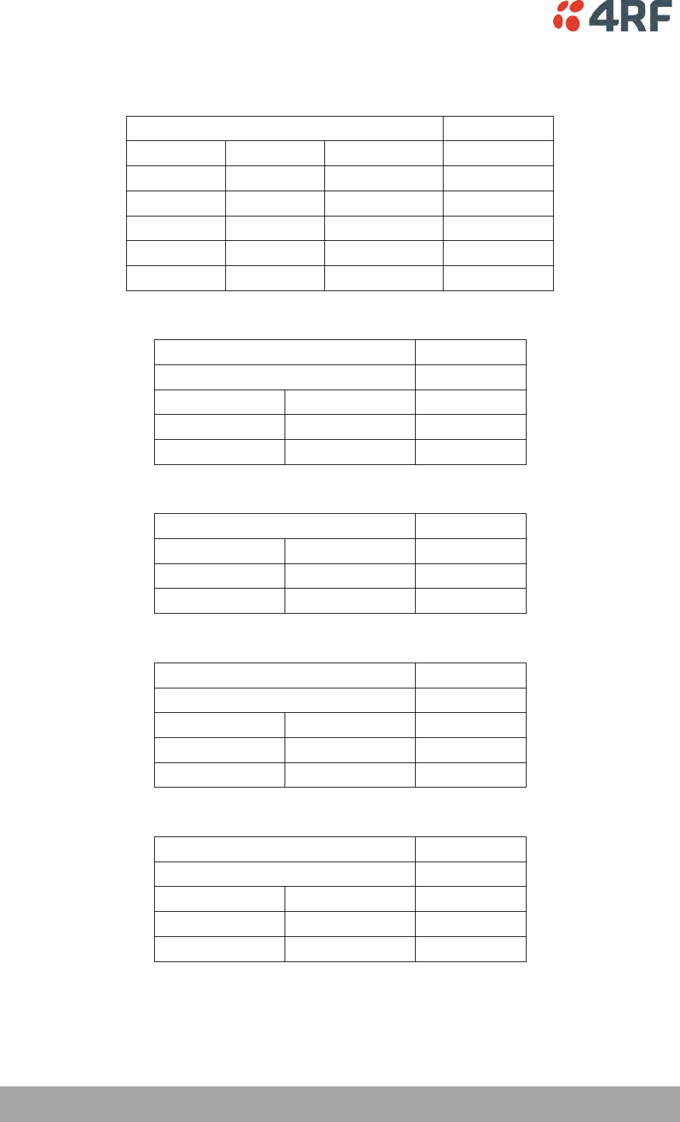
280 | Specifications
Aprisa SRi User Manual 1.0.0
Receiver
Receiver Sensitivity
50 kHz
BER < 10-2
64 QAM
Min coded FEC
-98 dBm
BER < 10-2
16 QAM
Min coded FEC
-106 dBm
BER < 10-2
QPSK
Min coded FEC
-111 dBm
BER < 10-6
64 QAM
Min coded FEC
-94 dBm
BER < 10-6
16 QAM
Min coded FEC
-102 dBm
BER < 10-6
QPSK
Min coded FEC
-107 dBm
Adjacent Channel Selectivity
50 kHz
Adjacent channel selectivity
> -37 dBm
BER < 10-2
64 QAM
> 53 dB
BER < 10-2
16 QAM
> 53 dB
BER < 10-2
QPSK
> 58 dB
Co-Channel Rejection
50 kHz
BER < 10-2
64 QAM
> –23 dB
BER < 10-2
16 QAM
> –19 dB
BER < 10-2
QPSK
> –12 dB
Intermodulation Response Rejection
50 kHz
Intermodulation response rejection
> -35 dBm
BER < 10-2
64 QAM
> 55 dB
BER < 10-2
16 QAM
> 55 dB
BER < 10-2
QPSK
> 60 dB
Blocking or Desensitization
50 kHz
Blocking or desensitization
> -17 dBm
BER < 10-2
64 QAM
> 73 dB
BER < 10-2
16 QAM
> 73 dB
BER < 10-2
QPSK
> 78 dB

Specifications | 281
Aprisa SRi User Manual 1.0.0
Spurious Response Rejection
50 kHz
Spurious response rejection
> -32 dBm
BER < 10-2
64 QAM
> 58 dB
BER < 10-2
16 QAM
> 58 dB
BER < 10-2
QPSK
> 63 dB
Receiver Spurious Radiation
50 kHz
Receiver spurious radiation
> -57 dBm
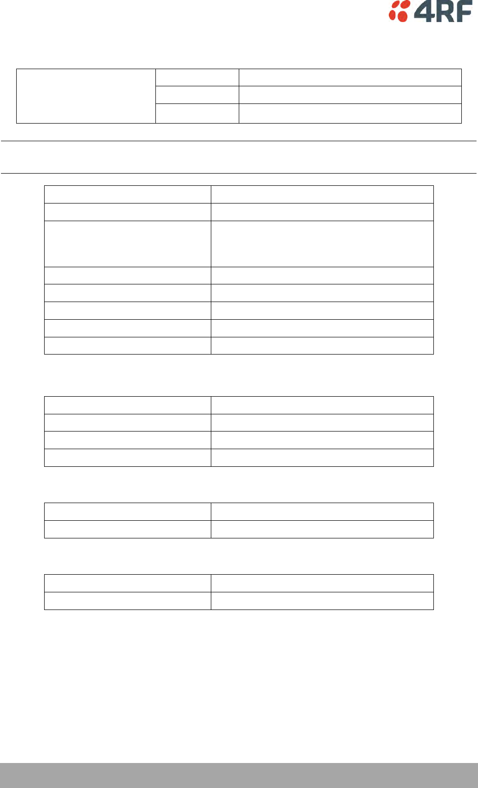
282 | Specifications
Aprisa SRi User Manual 1.0.0
Transmitter
Average Power output
64 QAM
0.005 to 0.2 W (+7 to +23 dBm, in 1 dB steps)
Note: The Peak Envelope Power
(PEP) at maximum set power
level is 1.0 W (+30 dBm).
16 QAM
0.006 to 0.25 W (+8 to +24 dBm, in 1 dB steps)
QPSK
0.01 to 0.4 W (+10 to +26 dBm, in 1 dB steps)
Note: The Aprisa SRi transmitter contains power amplifier protection which allows the antenna to be
disconnected from the antenna port without product damage.
Adjacent channel power
< - 60 dBc
Transient adjacent channel power
< - 60 dBc
Spurious emissions
< -20 dBc
< -49 dBm 800 MHz to 915 MHz
< -33 dBm 928 MHz to 1 GHz
Attack time
< 1.5 ms
Release time
< 0.5 ms
Data turnaround time
< 2 ms
Frequency stability
± 1.0 ppm
Frequency aging
< 1 ppm / annum
Spread Spectrum
Number of standard hop zones
8 (non-overlapping)
Zone / channel selection
Zone selection list and channel black list
Hop Frequency
62.5 kHz
Minimum number of channels
50
FCC / IC
Number of channels per hop zone
50
Full band option
400 channels full band single zone
ACMA / RSM
Number of channels per hop zone
25
Full band option
200 channels full band single zone

Specifications | 283
Aprisa SRi User Manual 1.0.0
Modem
Forward Error Correction
Variable length concatenated Reed Solomon
plus convolutional code
Adaptive Burst Support
Adaptive FEC
Adaptive Coding and Modulation
Data Payload Security
Data payload security
CCM* Counter with CBC-MAC
Data encryption
Counter Mode Encryption (CTR) using Advanced
Encryption Standard (AES) 128, 192 or 256
Data authentication
Cipher Block Chaining Message Authentication
Code (CBC-MAC) using Advanced Encryption
Standard (AES) 128, 192 or 256

284 | Specifications
Aprisa SRi User Manual 1.0.0
Interface Specifications
Ethernet Interface
The Aprisa SRi radio features an integrated 10Base-T/100Base-TX layer-2 Ethernet switch.
To simplify network setup, each port supports auto-negotiation and auto-sensing MDI/MDIX. Operators can
select from the following preset modes:
Auto negotiate
10Base-T half or full duplex
100Base-TX half or full duplex
The Ethernet ports are IEEE 802.3-compatible. The L2 Bridge (Switch) is IEEE 802.1d/q/p compatible, and
supports VLANs and VLAN manipulation of add/remove VLANs.
General
Interface
RJ45 x 2 (Integrated 2-port switch)
Cabling
CAT-5/6 UTP, supports auto MDIX (Standard Ethernet)
Maximum line length
100 metres on cat-5 or better
Bandwidth allocation
The Ethernet capacity maximum is determined by the
available radio link capacity.
Maximum transmission unit
Option setting of 1522 or 1536 octets
Address table size
1024 MAC addresses
Ethernet mode
10Base-T or 100Base-TX
Full duplex or half duplex
(Auto-negotiating and auto-sensing)
Diagnostics
Left Green LED
Off: no Ethernet signal received
On: Ethernet signal received
Right Orange LED
Off: no data present on the interface
Flashing: data present on the interface
Note: Do not connect Power over Ethernet (PoE) connections to the Aprisa SRi Ethernet ports as this will
damage the port.

Specifications | 285
Aprisa SRi User Manual 1.0.0
RS-232 Asynchronous Interface
The Aprisa SRi radio’s ITU-T V.24 compliant RS-232 interface is configured as a Cisco® pinout DCE. The
interface terminates to a DTE using a straight-through cable or to a DCE with a crossover cable (null
modem).
The interface uses two handshaking control lines between the DTE and the DCE.
General
Interface
ITU-T V.24 / EIA/TIA RS-232E
Interface direction
DCE only
Maximum line length
10 metres (dependent on baud rate)
Async
parameters
Standard mode data bits
7 or 8 bits
Standard mode parity
Configurable for None, Even or Odd
Standard mode stop bits
1 or 2 bits
Interface baud rates
300, 600, 1200, 2400, 4800, 9600, 19200, 38400, 57600 and
115200 bit/s
Control signals
DCE to DTE
CTS, RTS, DSR, DTR
Diagnostics
Left Green LED
Off: no RS-232 device connected
On: RS-232 device connected
Right Orange LED
Off: no data present on the interface
Flashing: data present on the interface
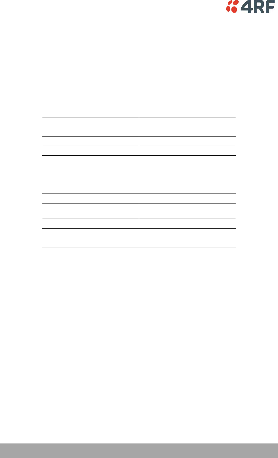
286 | Specifications
Aprisa SRi User Manual 1.0.0
Hardware Alarms Interface
The hardware alarms interface supports two alarm inputs and two alarms outputs.
Alarm Inputs
The alarm connector provides two hardware alarm inputs for alarm transmission to the other radios in the
network.
Interface
RJ45 connector
Detector type
Non-isolated ground referenced voltage
detector
Detection voltage - on
> +10 VDC
Detection voltage - off
< +4 VDC
Maximum applied input voltage
30 VDC
Maximum input current limit
10 mA
Alarm Outputs
The alarm connector provides two hardware alarm outputs for alarm reception from other radios in the
network.
Interface
RJ45 connector
Output type
Non-isolated ground referenced open
collector output
Maximum applied voltage
30 VDC
Maximum drive current
100 mA
Overload protection
Thermally resettable fuse
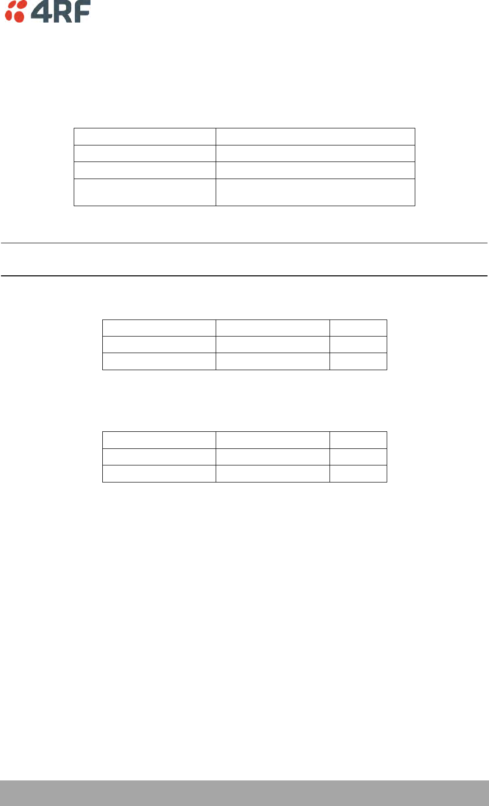
Specifications | 287
Aprisa SRi User Manual 1.0.0
Power Specifications
Power Supply
Aprisa SRi Radio
Nominal voltage
+13.8 VDC (negative earth)
Absolute input voltage range
+10 to +30 VDC
Maximum power input
20 W
Connector
Molex 2 pin male screw fitting
39526-4002
Power Consumption
Note: The radio power consumption is dependent on transmitter power, the type of traffic and network
activity.
Aprisa SRi Radio
Mode
Transmit Peak Power
13.8 VDC
Transmit / Receive
1.0 W
< 20 W
Receive only
< 7 W
Power Dissipation
Aprisa SRi Radio
Mode
Transmit Peak Power
13.8 VDC
Transmit / Receive
1.0 W
< 19 W
Receive only
< 7 W
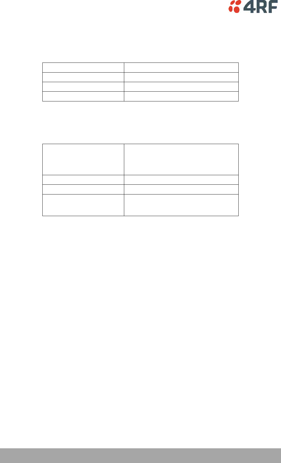
288 | Specifications
Aprisa SRi User Manual 1.0.0
General Specifications
Environmental
Operating temperature range
-40 to +70˚ C (-40 to +158˚ F)
Storage temperature range
-40 to +80˚ C (-40 to +176˚ F)
Operating humidity
Maximum 95% non-condensing
Acoustic noise emission
No audible noise emission
Mechanical
Aprisa SRi Radio
Dimensions
Width 210 mm (8.27”)
Depth 130 mm (5.12”) and 146 mm (5.748”)
with TNC connector
Height 41.5 mm (1.63”)
Weight
1.25 kg (2.81 lbs)
Colour
Matt black
Mounting
Wall (2 x M5 screws)
Rack shelf (4 x M4 screws)
DIN rail bracket

Specifications | 289
Aprisa SRi User Manual 1.0.0
Compliance
FCC
Radio
FCC CFR47 Part 15.247
EMC
47CFR part 15 Radio Frequency Devices
Safety
EN 60950-1:2006
Class 1 division 2 for hazardous locations
Environmental
ETS 300 019 Class 3.4
Ingress Protection IP51
IC
Radio
RSS-247
EMC
This Class A digital apparatus complies with
Canadian standard ICES-003.
Cet appareil numérique de la classe A est
conforme à la norme NMB-003 du Canada.
Safety
EN 60950-1:2006
Class 1 division 2 for hazardous locations
Environmental
ETS 300 019 Class 3.4
Ingress Protection IP51
ACMA
Radio
Radio Communications (Short Range Devices)
Standard 2004
EMC
AS/NZS 4268
Safety
EN 60950-1:2006
Class 1 division 2 for hazardous locations
Environmental
ETS 300 019 Class 3.4
Ingress Protection IP51
ACMA
Radio / EMC
AS/NZS 4268
Safety
EN 60950-1:2006
Class 1 division 2 for hazardous locations
Environmental
ETS 300 019 Class 3.4
Ingress Protection IP51

290 | Product End Of Life
Aprisa SRi User Manual 1.0.0
14. Product End Of Life
End-of-Life Recycling Programme (WEEE)
The WEEE Directive concerns the recovery, reuse, and recycling of electronic and electrical equipment.
Under the Directive, used equipment must be marked, collected separately, and disposed of properly.
4RF has implemented an end-of-life recycling programme to manage the reuse, recycling, and recovery of
waste in an environmentally safe manner using processes that comply with the WEEE Directive (EU Waste
Electrical and Electronic Equipment 2002/96/EC).
The WEEE Symbol Explained
This symbol appears on Electrical and Electronic Equipment (EEE) as part of the WEEE (Waste EEE)
directive. It means that the EEE may contain hazardous substances and must not be thrown away with
municipal or other waste.
WEEE Must Be Collected Separately
You must not dispose of electrical and electronic waste with municipal and other waste. You must
separate it from other waste and recycling so that it can be easily collected by the proper regional WEEE
collection system in your area.
YOUR ROLE in the Recovery of WEEE
By separately collecting and properly disposing of WEEE, you are helping to reduce the amount of WEEE
that enters the waste stream.
One of the aims of the WEEE directive is to divert EEE away from landfill and encourage recycling.
Recycling EEE means that valuable resources such as metals and other materials (which require energy to
source and manufacture) are not wasted. Also, the pollution associated with accessing new materials and
manufacturing new products is reduced.
EEE Waste Impacts the Environment and Health
Electrical and electronic equipment (EEE) contains hazardous substances which have potential effects on
the environment and human health. If you want environmental information on the Aprisa SRi radio,
contact us (see page 15).

Copyrights | 291
Aprisa SRi User Manual 1.0.0
15. Copyrights

Abbreviations | 293
Aprisa SRi User Manual 1.0.0
16. Abbreviations
AES Advanced Encryption Standard
AGC Automatic Gain Control
BER Bit Error Rate
CBC Cipher Block Chaining
CCM Counter with CBC-MAC integrity
DCE Data Communications Equipment
DTE Data Radio Equipment
EMC Electro-Magnetic Compatibility
EMI Electro-Magnetic Interference
ESD Electro-Static Discharge
ETSI European Telecommunications Standards
Institute
FW Firmware
HW Hardware
IF Intermediate Frequency
IP Internet Protocol
I/O Input/Output
ISP Internet Service Provider
kbit/s Kilobits per second
kHz Kilohertz
LAN Local Area Network
LED Light Emitting Diode
mA Milliamps
MAC Media Access Control
MAC Message Authentication Code
Mbit/s Megabits per second
MHz Megahertz
MIB Management Information Base
MTBF Mean Time Between Failures
MTTR Mean Time To Repair
ms milliseconds
NMS Network Management System
PC Personal Computer
PCA Printed Circuit Assembly
PLL Phase Locked Loop
ppm Parts Per Million
PMR Public Mobile Radio
RF Radio Frequency
RoHS Restriction of Hazardous Substances
RSSI Received Signal Strength Indication
RX Receiver
SNMP Simple Network Management Protocol
SNR Signal to Noise Ratio
SWR Standing Wave Ratio
TCP/IP Transmission Control Protocol/Internet
Protocol
TCXO Temperature Compensated Crystal Oscillator
TFTP Trivial File Transfer Protocol
TMR Trunk Mobile Radio
TX Transmitter
UTP Unshielded Twisted Pair
VAC Volts AC
VCO Voltage Controlled Oscillator
VDC Volts DC
WEEE Waste Electrical and Electronic Equipment

294 | Index
Aprisa SRi User Manual 1.0.0
17. Index
A
access rights 169
accessory kit 16
antennas
aligning 257
installing 57
selection and siting 47
siting 49
attenuators 45
B
bench setup 45
C
cabling
accessory kit 16
coaxial feeder 45, 50
CD contents 16
E
earthing 45, 50, 52
environmental requirements 51
F
feeder cables 50
front panel
connections 36
H
hardware
accessory kit 16
installing 57
humidity 51
I
interface connections 268
Ethernet 268
RS-232 Serial 269, 270
J
Java
requirement for 16, 62
L
lightning protection 52
linking system plan 50
logging in
SuperVisor 69
logging out
SuperVisor 70
M
maintenance summary 181
mounting kit 16
O
operating temperature 51
P
passwords
changing 170
path planning 47
path propagation calculator 47
pinouts
Ethernet 268
RS-232 Serial 269, 270
power supply 51
R
radio
earthing 45, 52
logging into 69
logging out 70
operating temperature 51
rebooting 184
storage temperature 51
rebooting the radio 184
RS-232
serial data 106
RS-232 Serial interface 105, 106, 112, 115
interface connections for 269, 270
port settings for 106

Index | 295
Aprisa SRi User Manual 1.0.0
S
security
settings160, 171, 176, 178, 195, 199, 201, 203,
205
summary 159, 173
security users
user privileges 169
SuperVisor
logging into 69
logging out 70
PC requirements for 62
PC settings for 65
T
temperature 51
tools 53
U
users
adding 169
changing passwords 170
deleting 170
user details 169
user privilege 170
W
WEEE 288