4RF SQ757M160 Digital Transceiver User Manual Part 3 of 3
4RF Limited Digital Transceiver Part 3 of 3
UserManual.wiki
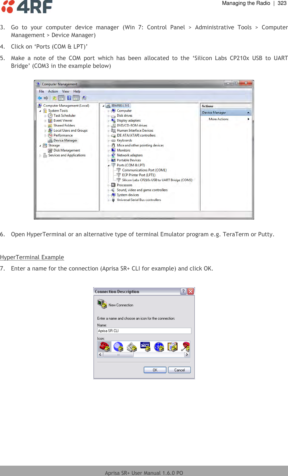
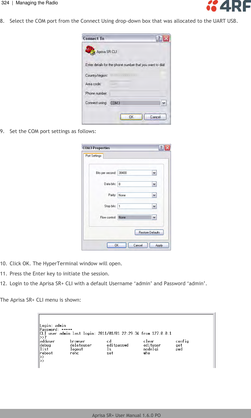
>
4RF
>
SQ757M160 User Manual
>
User Manual - Part 3 of 3
Contents
1.
User Manual - Part 1 of 3
2.
User Manual - Part 2 of 3
3.
User Manual - Part 3 of 3
User Manual - Part 3 of 3
Navigation menu
Upload a User Manual
Namespaces
Wiki Guide
HTML
PDF
Info
Views
User Manual
Discussion / Help
Navigation
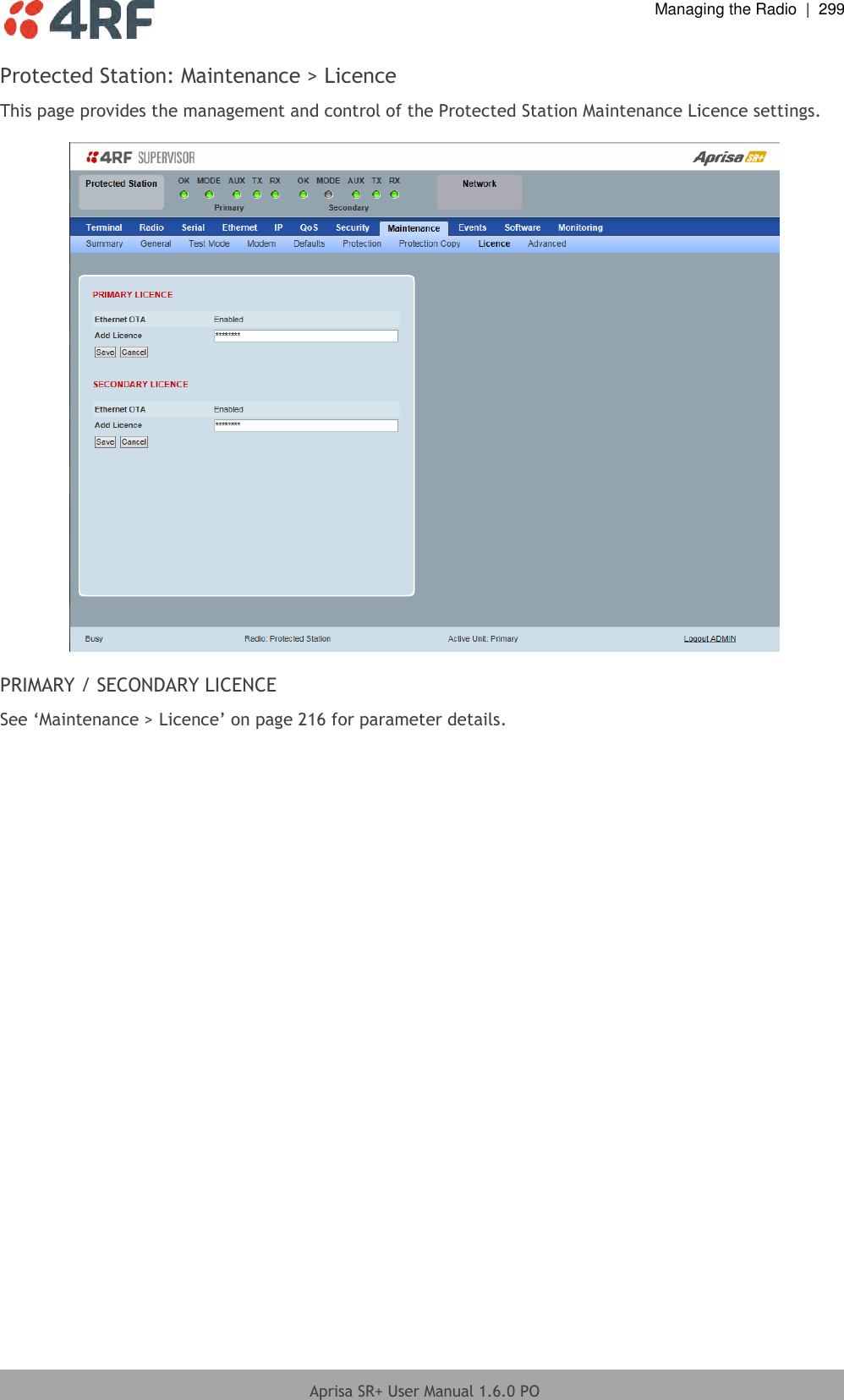
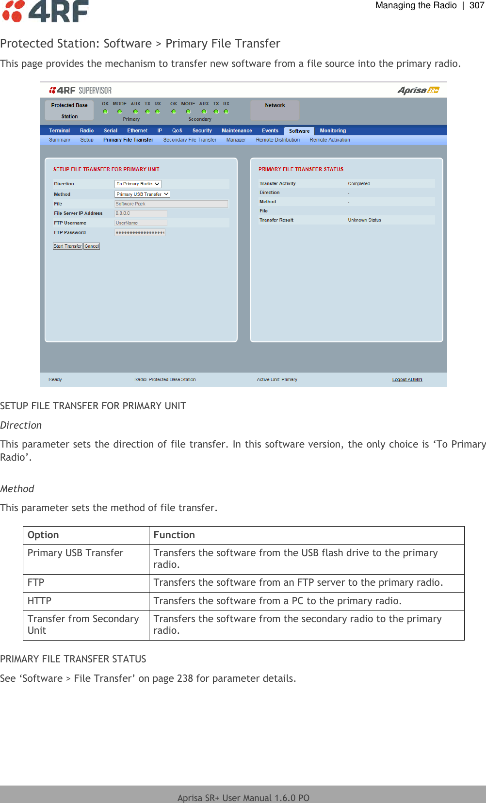
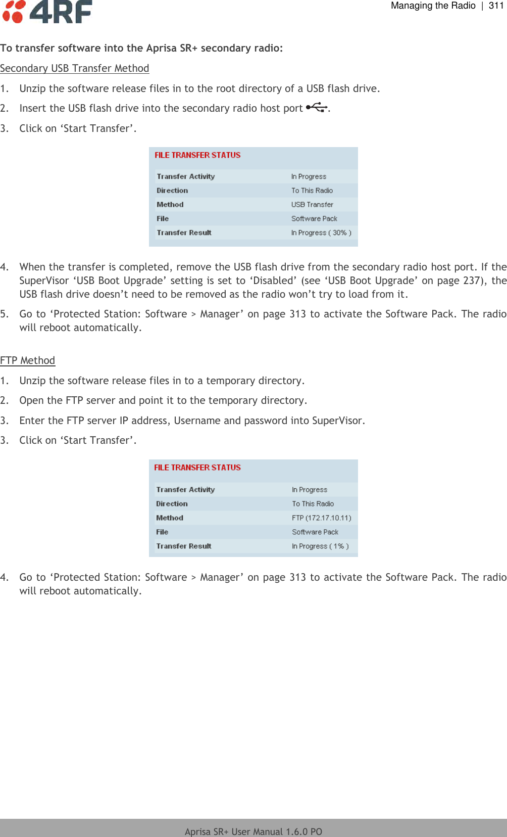
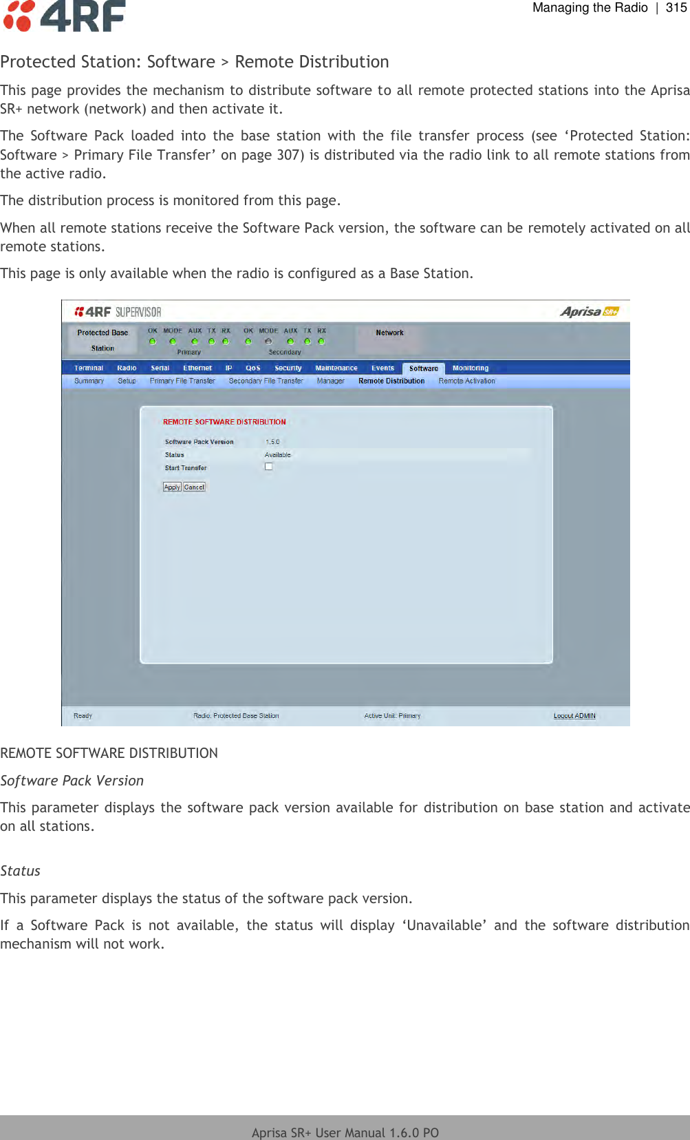
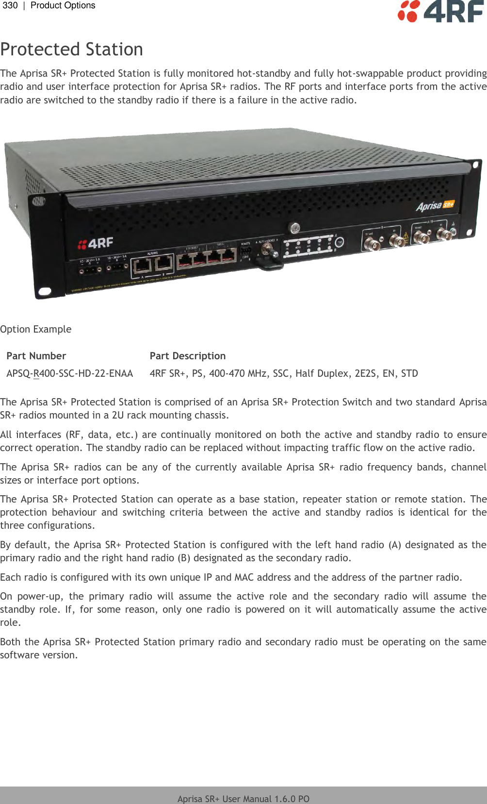
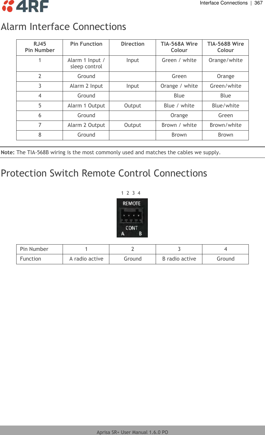
![Managing the Radio | 325 Aprisa SR+ User Manual 1.6.0 PO CLI Commands To enter a CLI command: 1. Type the first few characters of the command and hit Tab. This auto completes the command. 2. Enter the command string and enter. Note: All CLI commands are case sensitive. The top level CLI command list is displayed by typing a ? at the command prompt. The following is a list of the top level CLI commands and their usage: CLI Command Usage adduser adduser [-g <password aging>] [-a <account aging>] [-i <role>] <userName> <userPassword> browser browser <state(STR)> cd cd <changeMode(STR)> clear Clears the screen config config userdefault save restore factorydefault restore debug set subsystem param(INT) level param(INT) get clear subsystem param(INT) level param(INT) help log dump clear deleteuser deleteuser <userName> editpasswd editpasswd <oldpassword> <newpassword> edituser edituser [-p <password>] [-g <password aging>] [-a <account aging>] [-i] get get [-m <mib name>] [-n <module name>] <attribute name> [indexes] list list <tablename> logout Logs out from the CLI ls Displays the next level menu items pwd Displays the current working directory reboot Reboots the radio rohc stats show clear set set [-m <mib name> ] [-n <module name>] <attribute name> <attribute set value> [indexes] who Shows the users currently logged into the radio](https://usermanual.wiki/4RF/SQ757M160.User-Manual-Part-3-of-3/User-Guide-3093781-Page-27.png)