4RF SQ757M160 Digital Transceiver User Manual Part 3 of 3
4RF Limited Digital Transceiver Part 3 of 3
4RF >
Contents
- 1. User Manual - Part 1 of 3
- 2. User Manual - Part 2 of 3
- 3. User Manual - Part 3 of 3
User Manual - Part 3 of 3
Managing the Radio | 299
Aprisa SR+ User Manual 1.6.0 PO
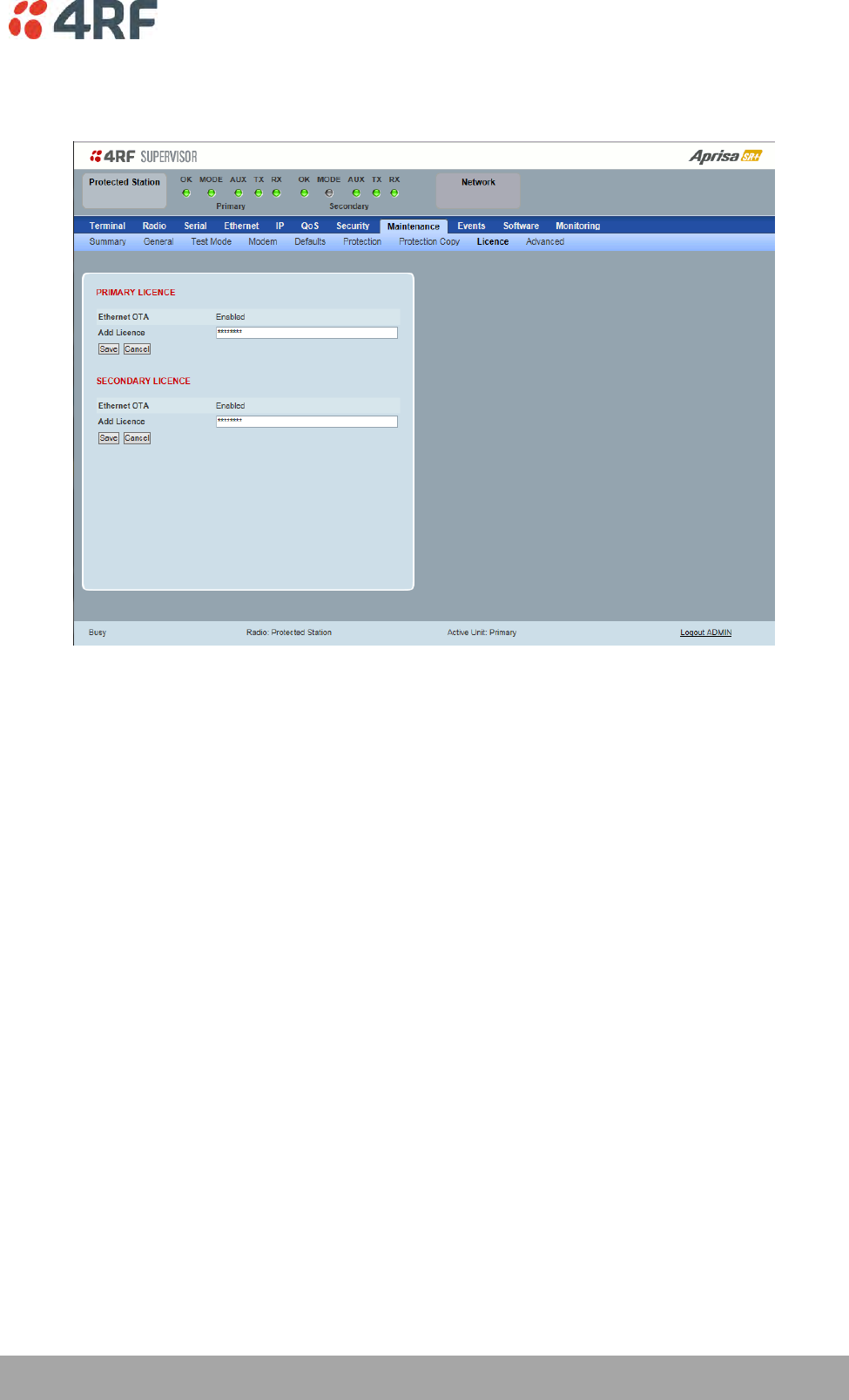
Protected Station: Maintenance > Licence
This page provides the management and control of the Protected Station Maintenance Licence settings.
PRIMARY / SECONDARY LICENCE
See ‘Maintenance > Licence’ on page 216 for parameter details.
300 | Managing the Radio
Aprisa SR+ User Manual 1.6.0 PO
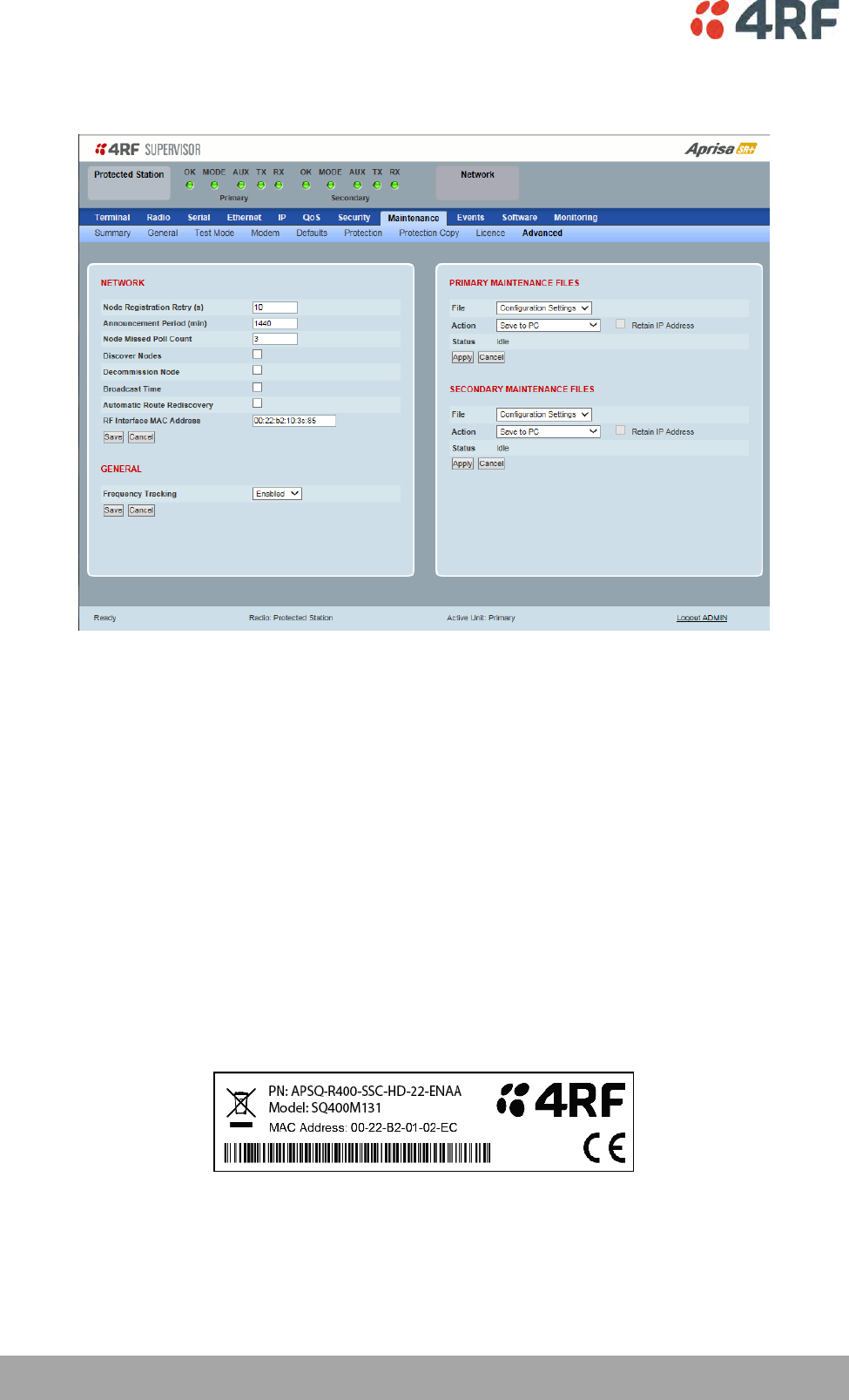
Protected Station: Maintenance > Advanced
This page provides the management and control of the Protected Station Maintenance Advanced settings.
NETWORK
See ‘Maintenance > Advanced’ on page 217 for parameter details.
RF Interface MAC address
This parameter is only applicable when the radio is part of a Protected Station.
This RF Interface MAC address is used to define the MAC address of the Protection Switch. This address is
entered in the factory. Both Protected Station radios read and use this MAC address.
This MAC address entry will only be used by the software if it detects that the factory MAC address set in
the internal EPROM of the protected switch is corrupted for some reason, otherwise the software will
ignore the MAC address entered by the user.
The RF interface MAC address is used for registration process only. For example, in a remote Protected
Station, both radios share the same RF MAC address and a single entry of the remote Protected Station
will be presented in network table (Network Status > Network Table).
The Protection Switch RF Interface MAC address is shown on the Protection Switch label:

Managing the Radio | 301
Aprisa SR+ User Manual 1.6.0 PO
PRIMARY / SECONDARY CONFIGURATION
See ‘Maintenance > Advanced’ on page 217 for parameter details.
PRIMARY / SECONDARY MAINTENANCE FILES
See ‘Maintenance > Advanced’ on page 217 for parameter details.
302 | Managing the Radio
Aprisa SR+ User Manual 1.6.0 PO
Events
The Events menu contains the setup and management of the alarms, alarm events and traps.
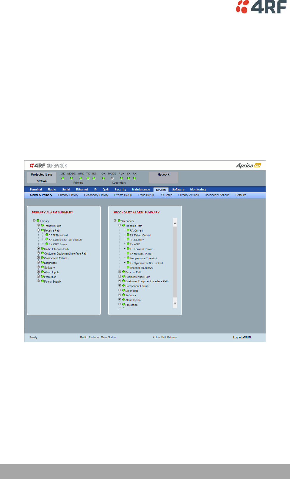
Protected Station: Events > Alarm Summary
There are two types of events that can be generated on the Aprisa SR+ radio. These are:
1. Alarm Events
Alarm Events are generated to indicate a problem on the radio.
2. Informational Events
Informational Events are generated to provide information on key activities that are occurring on the
radio. These events do not indicate an alarm on the radio and are used to provide information only.
See ‘Alarm Types and Sources’ on page 368 for a complete list of events.
PRIMARY / SECONDARY ALARM SUMMARY
See ‘Events > Alarm Summary’ on page 222 for parameter details.
Managing the Radio | 303
Aprisa SR+ User Manual 1.6.0 PO
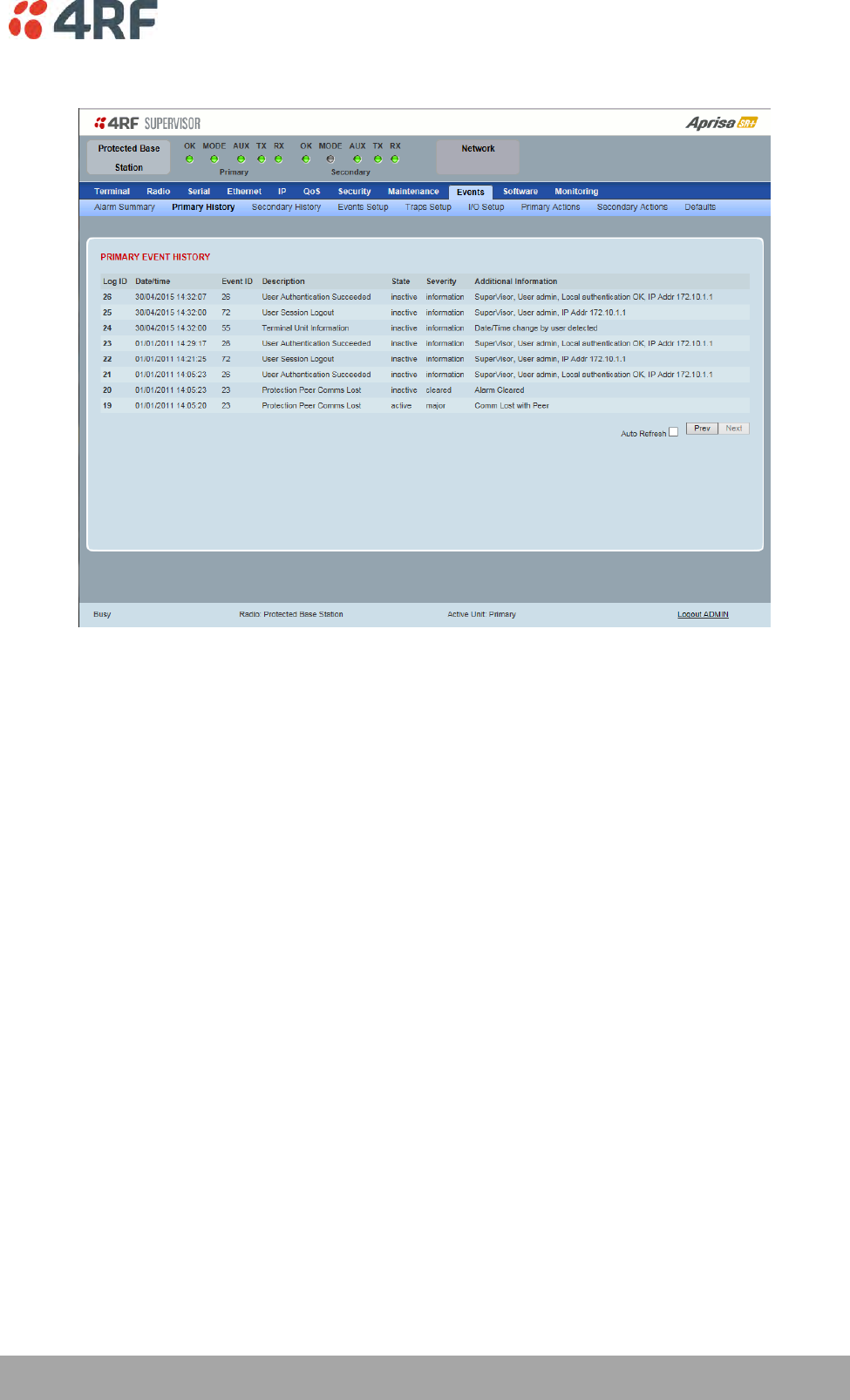
Protected Station: Events > Primary History
PRIMARY EVENT HISTORY
See ‘Events > Event History’ on page 223 for parameter details.
304 | Managing the Radio
Aprisa SR+ User Manual 1.6.0 PO
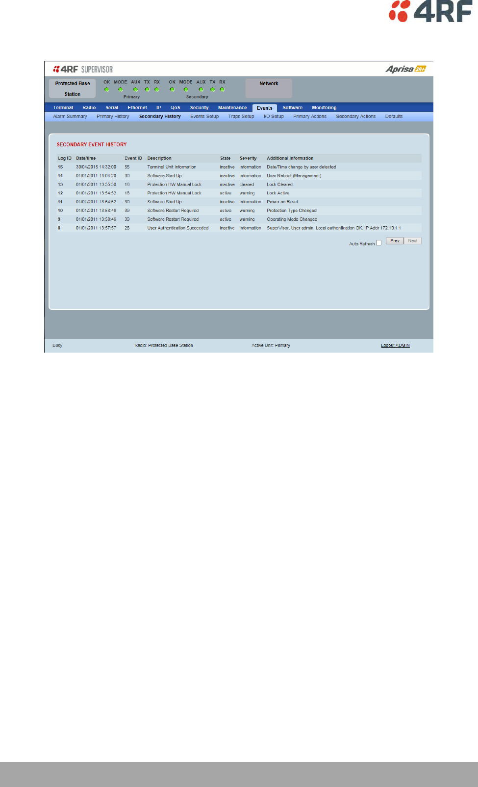
Protected Station: Events > Secondary History
SECONDARY EVENT HISTORY
See ‘Events > Event History’ on page 223 for parameter details.

Managing the Radio | 305
Aprisa SR+ User Manual 1.6.0 PO
Software
The Software menu contains the setup and management of the system software including network
software distribution and activation on a protected station.
Single Radio Software Upgrade
The radio software can be upgraded on a single radio single Aprisa SR+ radio (see ‘Single Radio Software
Upgrade’ on page 362). This process would only be used if the radio was a replacement or a new station in
an existing network.
Network Software Upgrade
The radio software can be upgraded on an entire Aprisa SR+ radio network remotely over the radio link
(see ‘Network Software Upgrade’ on page 358). This process involves the following steps:
1. Transfer the new software to base station primary radio with ‘Protected Station: Software > Primary
File Transfer’.
2. File Transfer the new software to base station secondary radio with ‘Protected Station: Software >
Secondary File Transfer’.
3. Using the Software Manual Lock, manually lock all protected remotes to the currently active radio
(this is necessary to prevent automatic switching during the distribution and activation process).
4. Distribute the new software to all remote stations with ‘Protected Station: Software > Remote
Distribution’. Note: The software pack in the base station active radio is used for distribution.
5. Activate of the new software on remote stations with ‘Protected Station: Software > Remote
Activation’.
6. Finally, activate the new software on the base station primary and secondary radios. Note: activating
the software will reboot the radio which will reset the Software Manual Lock to Automatic.
306 | Managing the Radio
Aprisa SR+ User Manual 1.6.0 PO
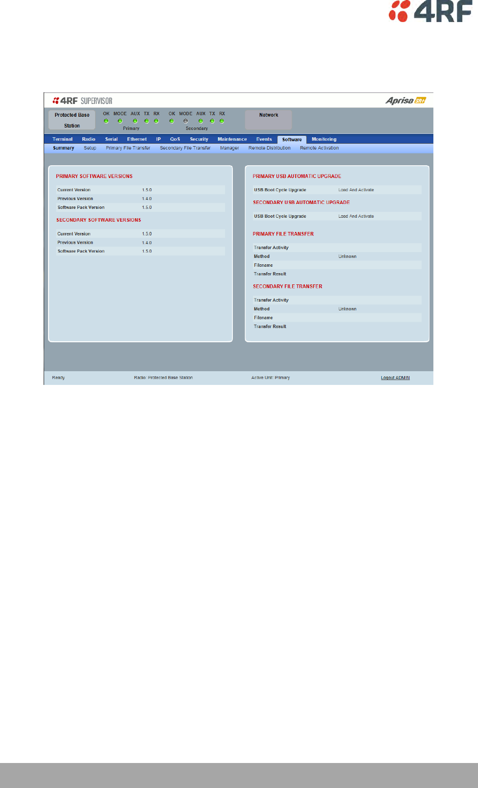
Protected Station: Software > Summary
This page provides a summary of the software versions installed on the radio, the setup options and the
status of the File Transfers.
PRIMARY / SECONDARY SOFTWARE VERSIONS
See ‘Protected Station: Software > Primary File Transfer’ and ‘Protected Station: Software > Secondary
File Transfer’ for parameter details.
Managing the Radio | 307
Aprisa SR+ User Manual 1.6.0 PO
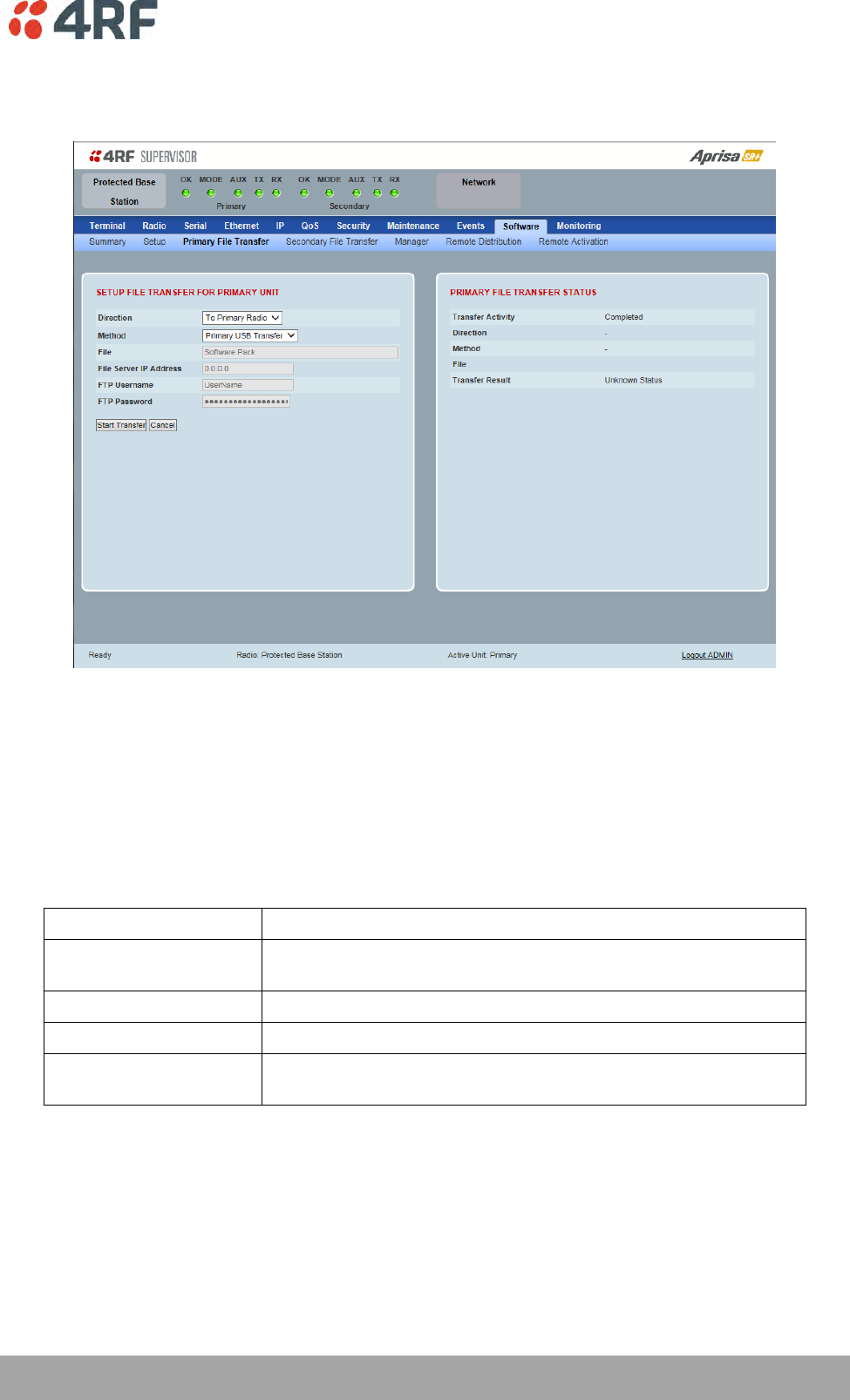
Protected Station: Software > Primary File Transfer
This page provides the mechanism to transfer new software from a file source into the primary radio.
SETUP FILE TRANSFER FOR PRIMARY UNIT
Direction
This parameter sets the direction of file transfer. In this software version, the only choice is ‘To Primary
Radio’.
Method
This parameter sets the method of file transfer.
Option
Function
Primary USB Transfer
Transfers the software from the USB flash drive to the primary
radio.
FTP
Transfers the software from an FTP server to the primary radio.
HTTP
Transfers the software from a PC to the primary radio.
Transfer from Secondary
Unit
Transfers the software from the secondary radio to the primary
radio.
PRIMARY FILE TRANSFER STATUS
See ‘Software > File Transfer’ on page 238 for parameter details.
308 | Managing the Radio
Aprisa SR+ User Manual 1.6.0 PO
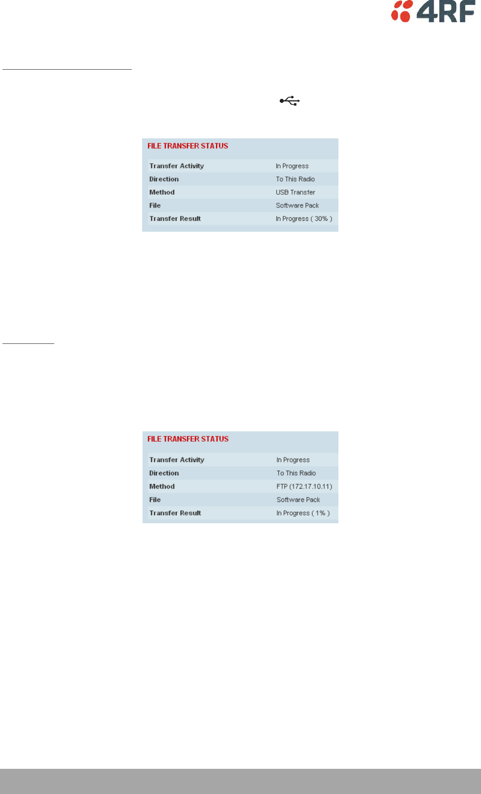
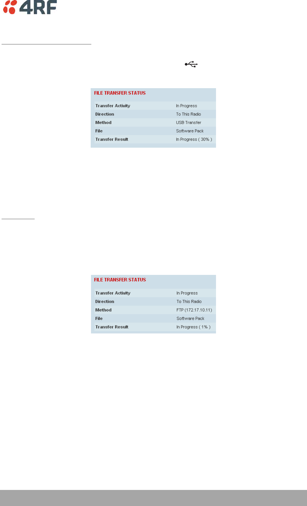
To transfer software into the Aprisa SR+ primary radio:
Primary USB Transfer Method
1. Unzip the software release files in to the root directory of a USB flash drive.
2. Insert the USB flash drive into the primary radio host port .
3. Click on ‘Start Transfer’.
4. When the transfer is completed, remove the USB flash drive from the primary radio host port. If the
SuperVisor ‘USB Boot Upgrade’ setting is set to ‘Disabled’ (see ‘USB Boot Upgrade’ on page 237), the
USB flash drive doesn’t need to be removed as the radio won’t try to load from it.
5. Go to ‘Protected Station: Software > Manager’ on page 313 to activate the Software Pack. The radio
will reboot automatically.
FTP Method
1. Unzip the software release files in to a temporary directory.
2. Open the FTP server and point it to the temporary directory.
3. Enter the FTP server IP address, Username and password into SuperVisor.
4. Click on ‘Start Transfer’.
5. Go to ‘Protected Station: Software > Manager’ on page 313 to activate the Software Pack. The radio
will reboot automatically.

Managing the Radio | 309
Aprisa SR+ User Manual 1.6.0 PO
Transfer from Secondary Unit
1. Select Transfer from Secondary Unit.
2. Click on ‘Start Transfer’.
3. Go to ‘Protected Station: Software > Manager’ on page 313 to activate the Software Pack. The radio
will reboot automatically.
If the file transfer fails, check the Event History page (see ‘Protected Station: Events > Secondary History’
on page 304) for more details of the transfer.
310 | Managing the Radio
Aprisa SR+ User Manual 1.6.0 PO
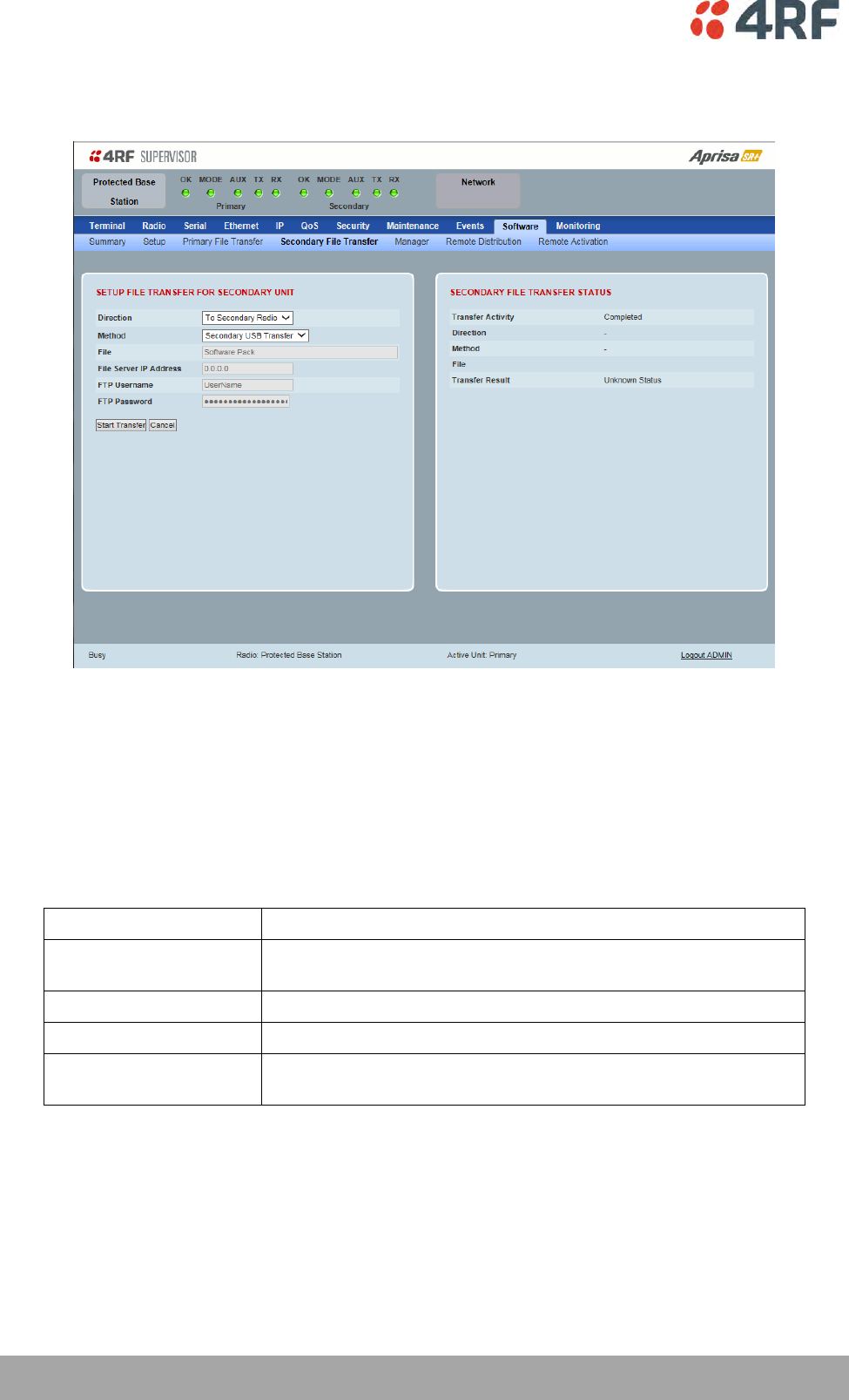
Protected Station: Software > Secondary File Transfer
This page provides the mechanism to transfer new software from a file source into the secondary radio.
SETUP FILE TRANSFER FOR SECONDARY UNIT
Direction
This parameter sets the direction of file transfer. In this software version, the only choice is ‘To Secondary
Radio’.
Method
This parameter sets the method of file transfer.
Option
Function
Secondary USB Transfer
Transfers the software from the USB flash drive to the secondary
radio.
FTP
Transfers the software from an FTP server to the secondary radio.
HTTP
Transfers the software from a PC to the secondary radio.
Transfer from Primary
Unit
Transfers the software from the primary radio to the secondary
radio.
SECONDARY FILE TRANSFER STATUS
See ‘Software > File Transfer’ on page 238 for parameter details.
Managing the Radio | 311
Aprisa SR+ User Manual 1.6.0 PO
To transfer software into the Aprisa SR+ secondary radio:
Secondary USB Transfer Method
1. Unzip the software release files in to the root directory of a USB flash drive.
2. Insert the USB flash drive into the secondary radio host port .
3. Click on ‘Start Transfer’.
4. When the transfer is completed, remove the USB flash drive from the secondary radio host port. If the
SuperVisor ‘USB Boot Upgrade’ setting is set to ‘Disabled’ (see ‘USB Boot Upgrade’ on page 237), the
USB flash drive doesn’t need to be removed as the radio won’t try to load from it.
5. Go to ‘Protected Station: Software > Manager’ on page 313 to activate the Software Pack. The radio
will reboot automatically.
FTP Method
1. Unzip the software release files in to a temporary directory.
2. Open the FTP server and point it to the temporary directory.
3. Enter the FTP server IP address, Username and password into SuperVisor.
3. Click on ‘Start Transfer’.
4. Go to ‘Protected Station: Software > Manager’ on page 313 to activate the Software Pack. The radio
will reboot automatically.

312 | Managing the Radio
Aprisa SR+ User Manual 1.6.0 PO
Transfer from Primary Unit
1. Select Transfer from Primary Unit.
2. Click on ‘Start Transfer’.
3. Go to ‘Protected Station: Software > Manager’ on page 313 to activate the Software Pack. The radio
will reboot automatically.
If the file transfer fails, check the Event History page (see ‘Protected Station: Events > Primary History’ on
page 303) for more details of the transfer.
Managing the Radio | 313
Aprisa SR+ User Manual 1.6.0 PO
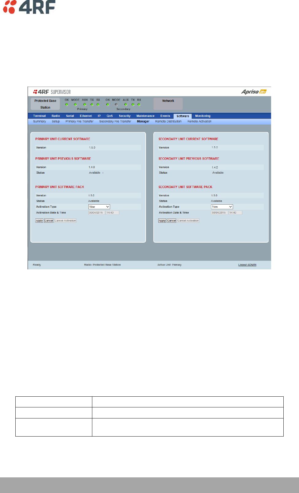
Protected Station: Software > Manager
This page summaries and manages the software versions available in the primary and secondary radios.
The manager is predominantly used to activate new software on single radios. Network activation is
performed with ‘Protected Station: Software > Remote Activation’.
Both the previous software (if available) and Software Pack versions can be activated on each radio from
this page.
PRIMARY / SECONDARY CURRENT SOFTWARE
Version
This parameter displays the software version running on the radio.
PRIMARY / SECONDARY PREVIOUS SOFTWARE
Version
This parameter displays the software version that was running on the radio prior to the current software
being activated.
Status
This parameter displays the status of the software version running on the radio.
Option
Function
Active
The software is operating the radio.
Inactive
The software is not operating the radio but could be re-activated if
required.

314 | Managing the Radio
Aprisa SR+ User Manual 1.6.0 PO
PRIMARY / SECONDARY SOFTWARE PACK
Version
This parameter displays the software pack version available for distribution on base station and activate
on all stations.
Status
This parameter displays the status of the software pack version.
Option
Function
Available
On the base station, the software pack is available for distribution.
On all stations, the software pack is available for activation.
Activating
The software pack is activating in the radio.
Unavailable
There is no software pack loaded into the radio.
Activate
See ‘Software > Manager’ on page 242 for the activation options.
Managing the Radio | 315
Aprisa SR+ User Manual 1.6.0 PO
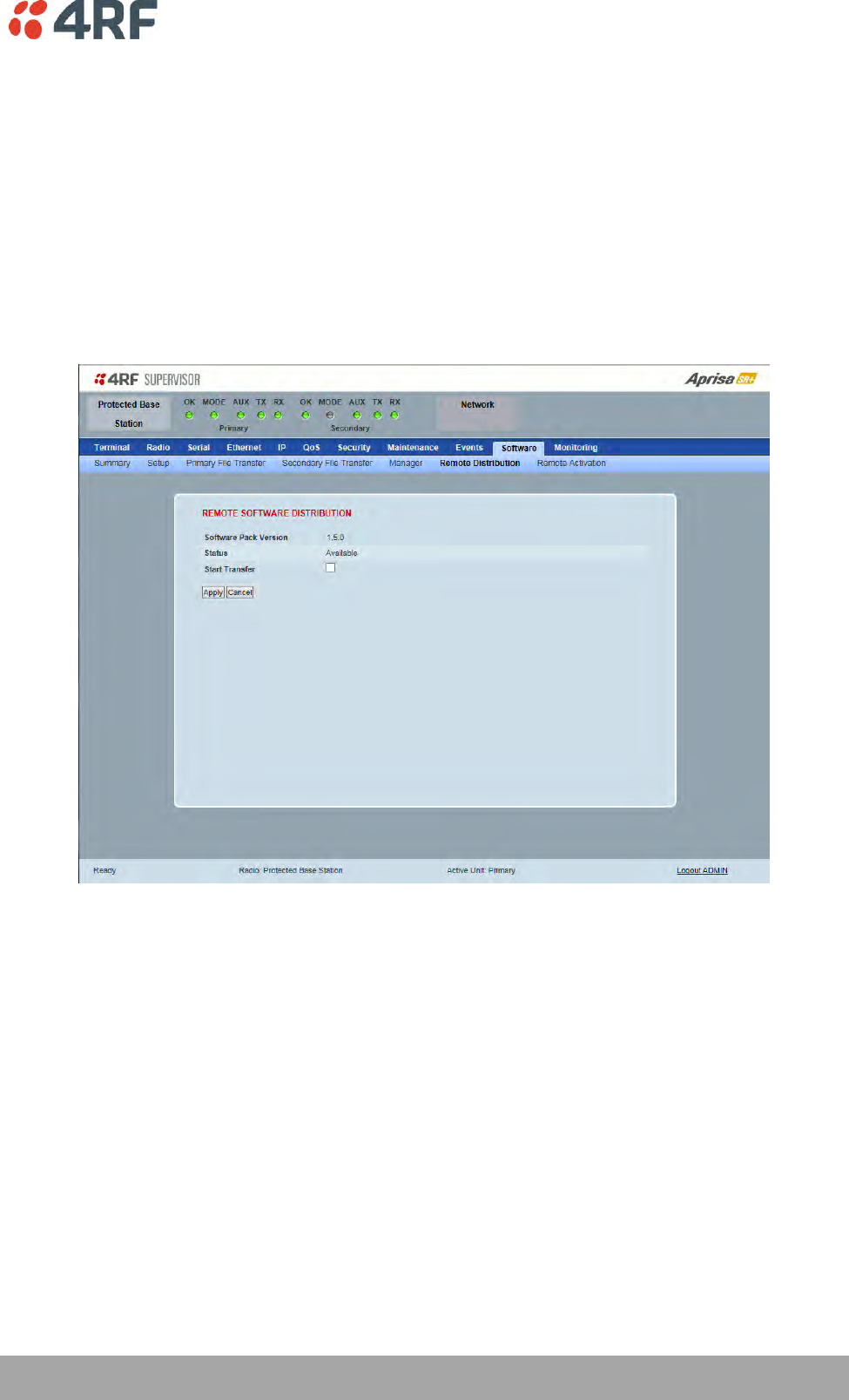
Protected Station: Software > Remote Distribution
This page provides the mechanism to distribute software to all remote protected stations into the Aprisa
SR+ network (network) and then activate it.
The Software Pack loaded into the base station with the file transfer process (see ‘Protected Station:
Software > Primary File Transfer’ on page 307) is distributed via the radio link to all remote stations from
the active radio.
The distribution process is monitored from this page.
When all remote stations receive the Software Pack version, the software can be remotely activated on all
remote stations.
This page is only available when the radio is configured as a Base Station.
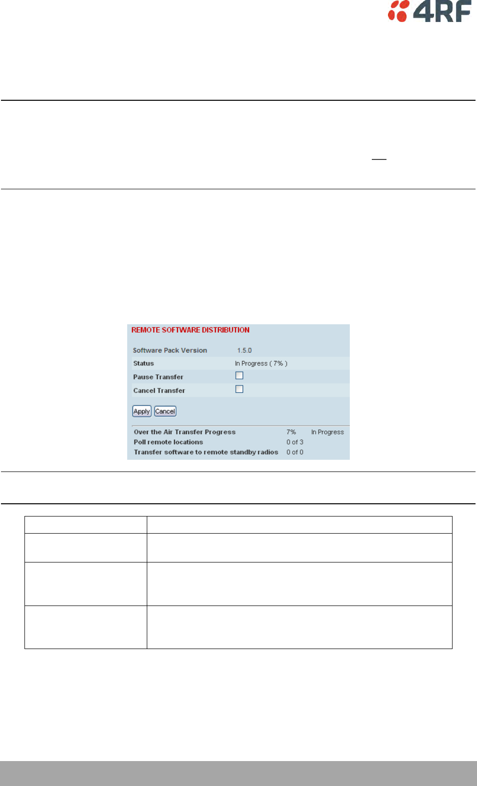
REMOTE SOFTWARE DISTRIBUTION
Software Pack Version
This parameter displays the software pack version available for distribution on base station and activate
on all stations.
Status
This parameter displays the status of the software pack version.
If a Software Pack is not available, the status will display ‘Unavailable’ and the software distribution
mechanism will not work.
316 | Managing the Radio
Aprisa SR+ User Manual 1.6.0 PO
Start Transfer
This parameter when activated distributes (broadcasts) the new Software Pack to all remote stations in
the network.
Note: The distribution of software to remote stations does not stop customer traffic from being
transferred. However, due to the volume of traffic, the software distribution process may affect customer
traffic.
Software distribution traffic is classified as ‘management traffic’ but does not use the Ethernet
management priority setting. Software distribution traffic priority has a fixed priority setting of ‘very
low’.
To distribute software to remote stations:
This process assumes that a Software Pack has been loaded into the base station with the file transfer
process (see ‘Protected Station: Software > Primary File Transfer’ on page 307).
1. To ensure that the Network Table is up to date, it is recommended running the node discover function
(see ‘Discover Nodes’ on page 218).
2. Click on ‘Start Transfer’.
Note: This process could take anywhere between 40 minutes and several hours depending on channel size,
Ethernet Management Priority setting and the amount of customer traffic on the network.
Result
Function
Over the Air Transfer
Progress
The percentage of the software pack that has been broadcast to
the remote radios.
Poll Remote Locations
X is the number of radios polled to determine the number of
standby radios.
Y is the number of remote radios registered with the base station.
Transfer software to
remote standby radios
X is the number of standby radios with the new software version.
Y is the number of standby radios requiring the new software
version.
3. When the distribution is completed, activate the software with the Remote Software Activation.

Managing the Radio | 317
Aprisa SR+ User Manual 1.6.0 PO
Pause Transfer
This parameter when activated, pauses the Over the Air Transfer Process and shows the distribution
status. The distribution process will continue from where it was paused with Resume Transfer.
Cancel Transfer
This parameter when activated, cancels the Over the Air Transfer Process immediately.
During the distribution process, it is possible to navigate away from this page and come back to it to check
progress. The SuperVisor session will not timeout.
318 | Managing the Radio
Aprisa SR+ User Manual 1.6.0 PO
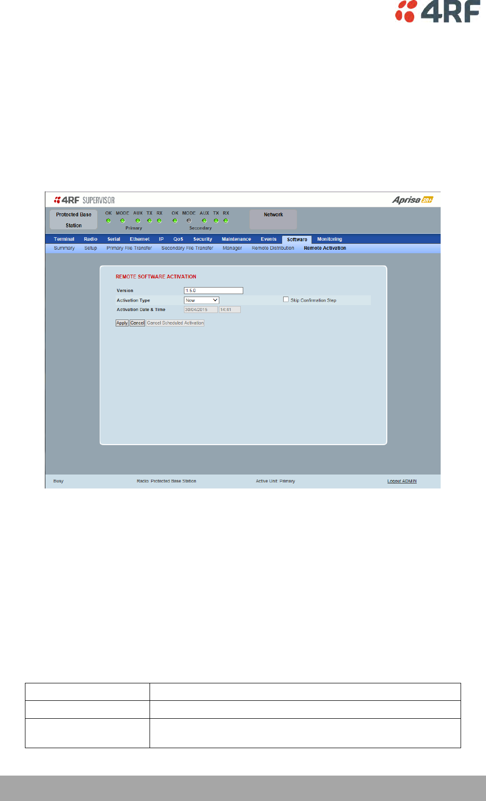
Protected Station: Software > Remote Activation
This page provides the mechanism to activate software on all remote protected stations.
The Software Pack has been loaded into the base station with the file transfer process (see ‘Protected
Station: Software > Primary File Transfer’ on page 307) and distributed via the radio link to all remote
stations from the active radio.
When all remote stations receive the Software Pack version, the software can be remotely activated on all
remote stations.
The activation process is monitored by this page.
This page is only available when the radio is configured as a Base Station.
REMOTE SOFTWARE ACTIVATION
When the software pack version has been distributed to all the remote stations, the software is then
activated in all the remote stations with this command. If successful, then activate the software pack in
the base station to complete the network upgrade.
Version
This parameter displays the software version for activation. The default version is the software pack
version but any valid software version can be entered in the format ‘n.n.n’.
Activation Type
This parameter sets when the software pack activation will occur.
Option
Function
Now
Activates the software pack now.
Date & Time
Activates the software pack at the Date & Time set in the following
parameter.
Managing the Radio | 319
Aprisa SR+ User Manual 1.6.0 PO
Activation Date & Time
This parameter sets the Date & Time when the software pack activation will occur.
This setting can be any future date and 24 hour time.
Skip Confirmation Step
This parameter when enabled skips the confirmation step during the activation process.
Normally, the confirmation step will require use intervention to accept the confirmation which will halt
the activation process. Skipping the confirmation will enable the activation process to continue without
use intervention.
To activate software in remote stations:
This process assumes that a Software Pack has been loaded into the base station with the file transfer
process (see ‘Software > File Transfer’ on page 238) and that distributed to all remote radios in the
network.
Note: Do not navigate SuperVisor away from this page during the activation process (SuperVisor can lose
PC focus).
1. Enter the Software Pack version (if different from displayed version).
2. See ‘Software > Manager’ on page 242 for the activation options.
320 | Managing the Radio
Aprisa SR+ User Manual 1.6.0 PO
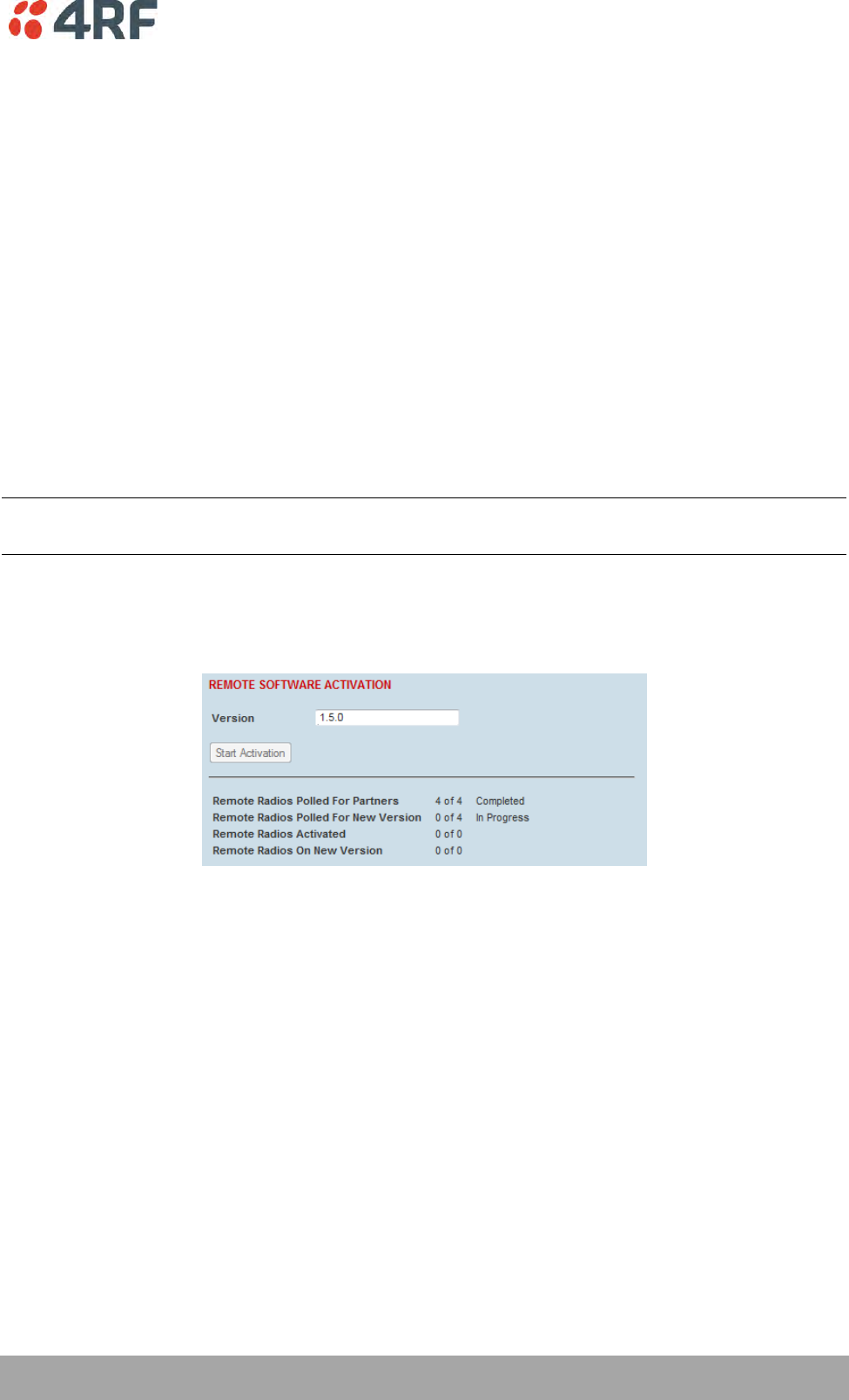
The remote stations will be polled to determine which radios require activation:
Result
Function (X of Y)
Remote Radios Polled for
Partners
X is the number of radios polled to determine the number of
protected stations in the network.
Y is the number of remote radios registered with the base station.
Remote Radios Polled for
New Version
X is the number of radios polled to determine the number of radios
that contain the new software version.
Y is the number of remote radios registered with the base station.
Remote Radios Activated
X is the number of radios that contain the new software version
and have been activated.
Y is the number of radios that contain the new software version
and can be activated.
Remote Radios On New
Version
X is the number of radios that has been successfully activated and
now running the new version of software.
Y is the number of radios that the activation command was
executed on.
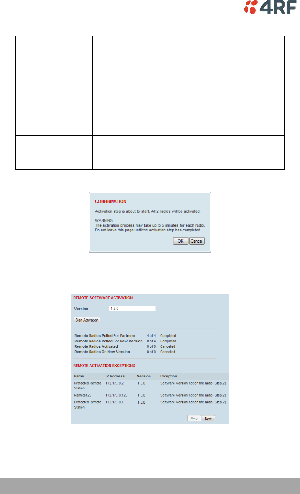
When the activation is ready to start:
3. Click on ‘OK’ to start the activation process or Cancel to quit.
The page will display the progress of the activation.
The example shows that during the activation process there were exceptions that may need to be
investigated.

Managing the Radio | 321
Aprisa SR+ User Manual 1.6.0 PO
When all the remote radios have been activated, the base station radio must now be activated with (see
‘Software > Manager’ on page 242).
4. Click on ‘OK’ to start the activation on the base station.
322 | Managing the Radio
Aprisa SR+ User Manual 1.6.0 PO
Command Line Interface
The Aprisa SR+ has a Command Line Interface (CLI) which provides basic product setup and configuration.
This can be useful if you need to confirm the radio’s IP address, for example.
You can password-protect the Command Line Interface to prevent unauthorized users from modifying
radio settings.
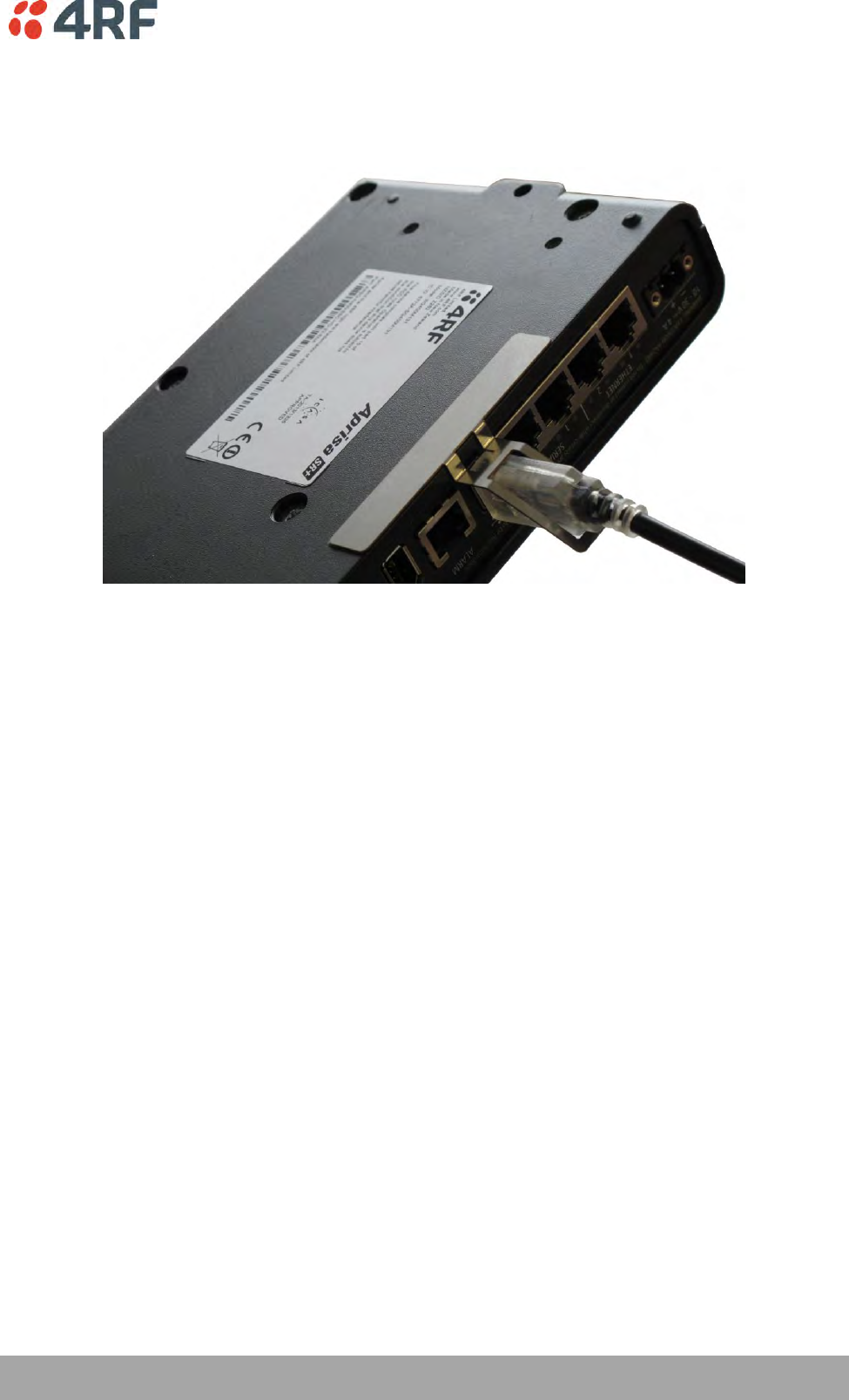
This interface can be accessed via an Ethernet Port (RJ45), the Management Port (USB micro type B) or
the USB host port with a USB converter to RS-232 convertor.
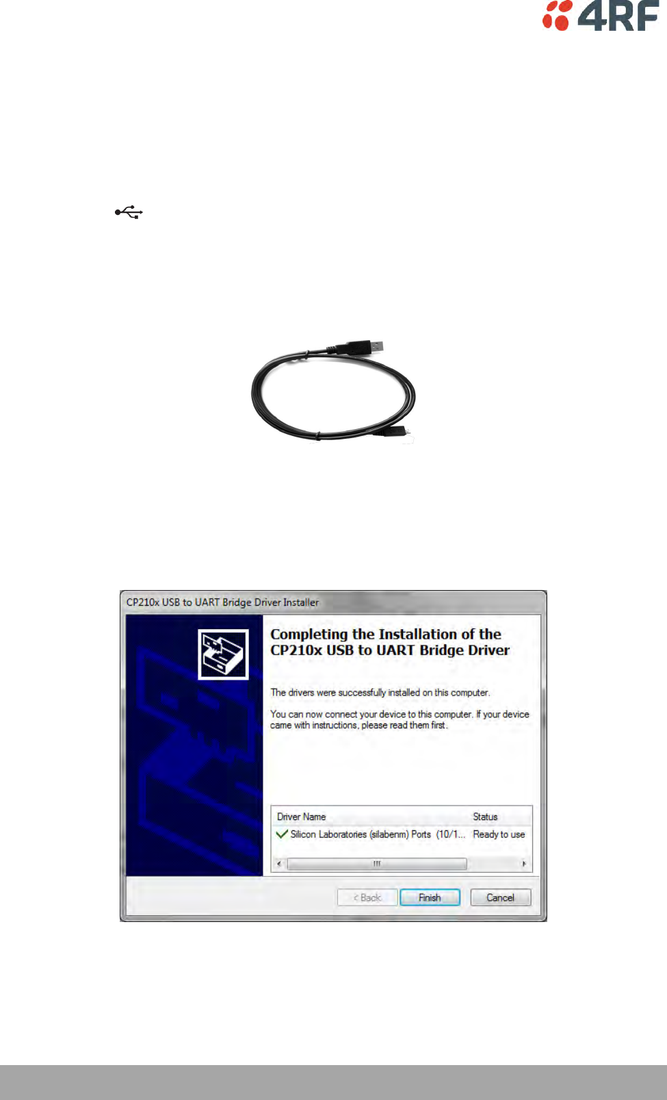
Connecting to the Management Port
A USB Cable USB A to USB micro B, 1m is provided with each radio.
1. Connect the USB A to your computer USB port and the USB micro B to the management port of the
Aprisa SR+ (MGMT).
2. Unzip the file ‘USB Serial Driver CP210x_VCP_Windows.zip’ to a temporary location and install the
appropriate driver on your computer. This file is on the Information and setup CD supplied with the
radio.
Managing the Radio | 323
Aprisa SR+ User Manual 1.6.0 PO
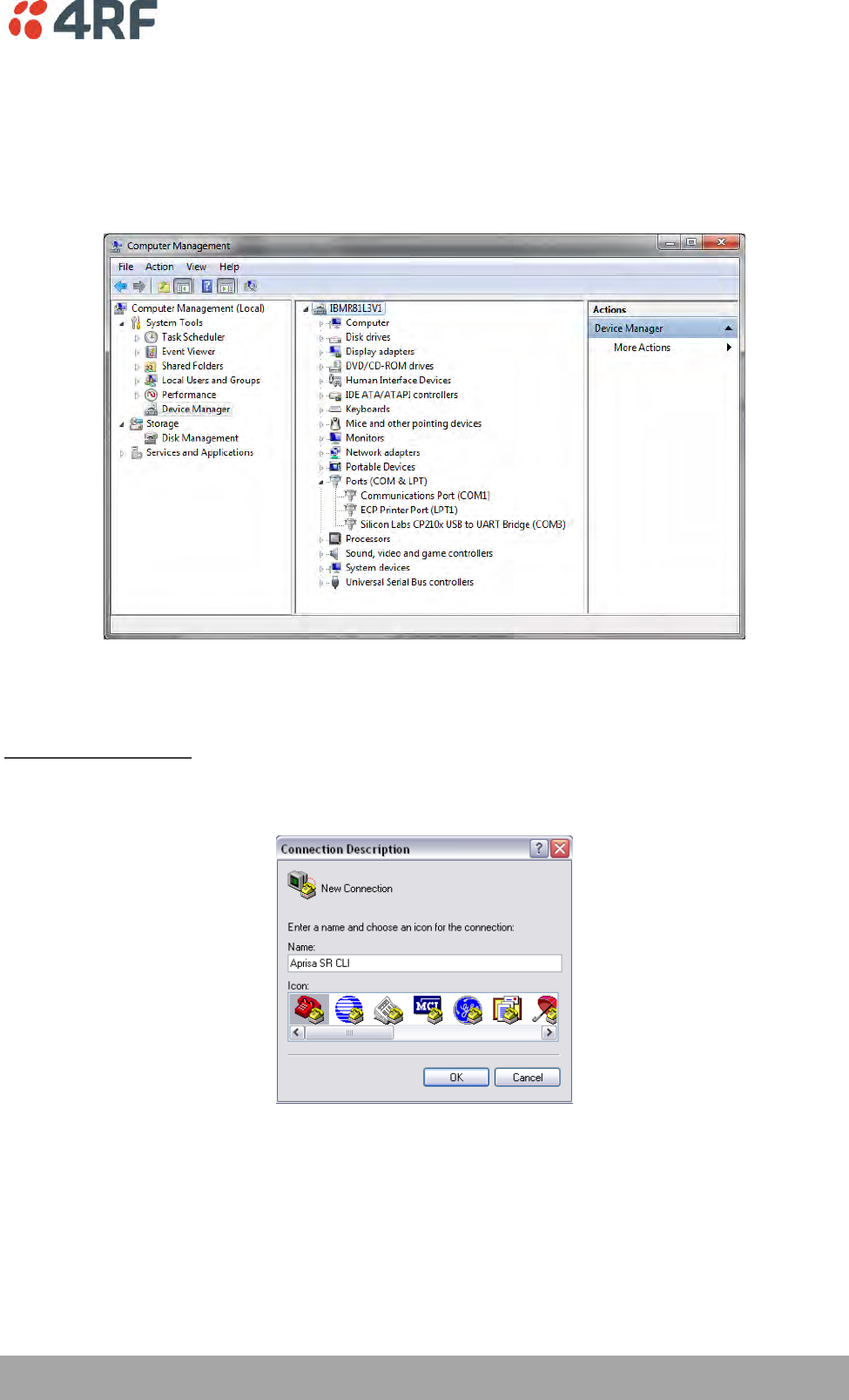
3. Go to your computer device manager (Win 7: Control Panel > Administrative Tools > Computer
Management > Device Manager)
4. Click on ‘Ports (COM & LPT)’
5. Make a note of the COM port which has been allocated to the ‘Silicon Labs CP210x USB to UART
Bridge’ (COM3 in the example below)
6. Open HyperTerminal or an alternative type of terminal Emulator program e.g. TeraTerm or Putty.
HyperTerminal Example
7. Enter a name for the connection (Aprisa SR+ CLI for example) and click OK.
324 | Managing the Radio
Aprisa SR+ User Manual 1.6.0 PO
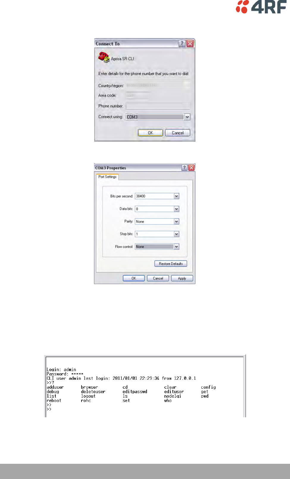
8. Select the COM port from the Connect Using drop-down box that was allocated to the UART USB.
9. Set the COM port settings as follows:
10. Click OK. The HyperTerminal window will open.
11. Press the Enter key to initiate the session.
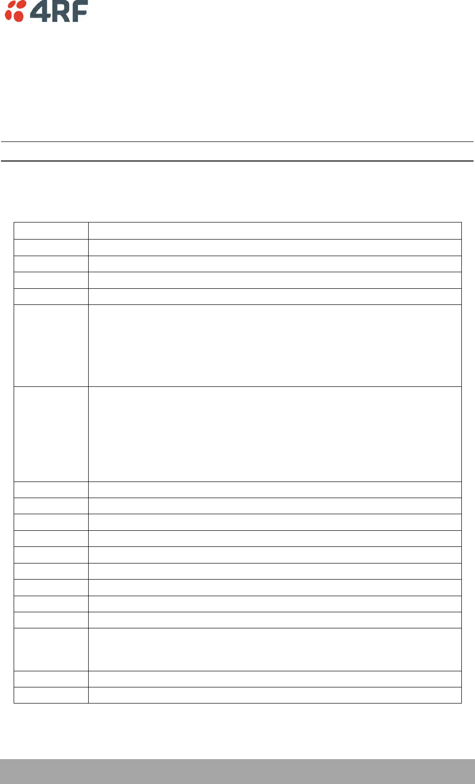
12. Login to the Aprisa SR+ CLI with a default Username ‘admin’ and Password ‘admin’.
The Aprisa SR+ CLI menu is shown:
Managing the Radio | 325
Aprisa SR+ User Manual 1.6.0 PO
CLI Commands
To enter a CLI command:
1. Type the first few characters of the command and hit Tab. This auto completes the command.
2. Enter the command string and enter.
Note: All CLI commands are case sensitive.
The top level CLI command list is displayed by typing a ? at the command prompt.
The following is a list of the top level CLI commands and their usage:
CLI Command
Usage
adduser
adduser [-g <password aging>] [-a <account aging>] [-i <role>] <userName> <userPassword>
browser
browser <state(STR)>
cd
cd <changeMode(STR)>
clear
Clears the screen
config
config
userdefault
save
restore
factorydefault
restore
debug
set subsystem param(INT) level param(INT)
get
clear subsystem param(INT) level param(INT)
help
log
dump
clear
deleteuser
deleteuser <userName>
editpasswd
editpasswd <oldpassword> <newpassword>
edituser
edituser [-p <password>] [-g <password aging>] [-a <account aging>] [-i]
get
get [-m <mib name>] [-n <module name>] <attribute name> [indexes]
list
list <tablename>
logout
Logs out from the CLI
ls
Displays the next level menu items
pwd
Displays the current working directory
reboot
Reboots the radio
rohc
stats
show
clear
set
set [-m <mib name> ] [-n <module name>] <attribute name> <attribute set value> [indexes]
who
Shows the users currently logged into the radio
326 | Managing the Radio
Aprisa SR+ User Manual 1.6.0 PO
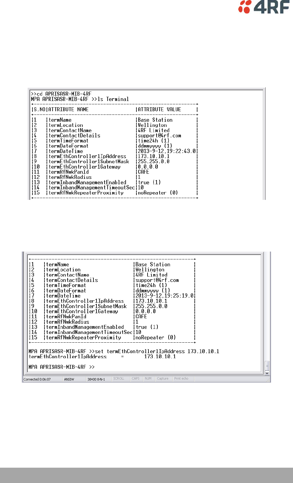
Viewing the CLI Terminal Summary
At the command prompt, type:
cd APRISASR-MIB-4RF
MPA APRISASR-MIB-4RF >>ls Terminal
Changing the Radio IP Address with the CLI
At the command prompt, type ‘set termEthController1IpAddress xxx.xxx.xxx.xxx’

In-Service Commissioning | 327
Aprisa SR+ User Manual 1.6.0 PO
8. In-Service Commissioning
Before You Start
When you have finished installing the hardware, RF and the traffic interface cabling, the system is ready
to be commissioned. Commissioning the radio is a simple process and consists of:
1. Powering up the radios.
2. Configuring all radios in the network using SuperVisor.
3. Aligning the antennas.
4. Testing that the links are operating correctly.
5. Connecting up the client or user interfaces.
What You Will Need
Appropriately qualified commissioning staff at both ends of each link.
Safety equipment appropriate for the antenna location at both ends of each link.
Communication equipment, that is, mobile phones or two-way radios.
SuperVisor software running on an appropriate laptop, computer, or workstation at the base
station radio.
Tools to facilitate loosening and re-tightening the antenna pan and tilt adjusters.
Predicted receiver input levels and fade margin figures from the radio link budget.

328 | In-Service Commissioning
Aprisa SR+ User Manual 1.6.0 PO
Antenna Alignment
A base station omni-directional collinear antenna has a vertical polarization. The remote station yagi
antennas must also have vertical polarization.
Aligning the Antennas
Align the remote station yagi antennas by making small adjustments while monitoring the RSSI. The Aprisa
SR+ has a Test Mode which presents a real time visual display of the RSSI on the front panel LEDs. This can
be used to adjust the antenna for optimum signal strength (see ‘Test Mode’ on page 44).
Note: Low gain antennas need less adjustment in elevation as they are simply aimed at the horizon. They
should always be panned horizontally to find the peak signal.
1. Press and hold the TEST button on the radio LED panel until all the LEDs flash green (about 3 - 5
seconds).
Note: The time for the LEDs to display the RSSI result is variable, depending on the network traffic,
and can be up to 5 seconds. Small antenna adjustments should be made and then wait for the display
to refresh.
The RSSI poll refresh rate can be set with the SuperVisor command ‘Transmit Period’ (see
‘Maintenance > Test Mode’ on page 210).
2. Move the antenna through a complete sweep horizontally (pan). Note down the RSSI reading for all the
peaks in RSSI that you discover in the pan.
3. Move the antenna to the position corresponding to the maximum RSSI value obtained during the pan.
Move the antenna horizontally slightly to each side of this maximum to find the two points where the
RSSI drops slightly.
4. Move the antenna halfway between these two points and tighten the clamp.
5. If the antenna has an elevation adjustment, move the antenna through a complete sweep (tilt)
vertically. Note down the RSSI reading for all the peaks in RSSI that you discover in the tilt.
6. Move the antenna to the position corresponding to the maximum RSSI value obtained during the tilt.
Move the antenna slightly up and then down from the maximum to find the two points where the RSSI
drops slightly.
7. Move the antenna halfway between these two points and tighten the clamp.
8. Recheck the pan (steps 2-4) and tighten all the clamps firmly.
9. To exit Test Mode, press and hold the TEST button until all the LEDs flash red (about 3 – 5 seconds).
Product Options | 329
Aprisa SR+ User Manual 1.6.0 PO
9. Product Options
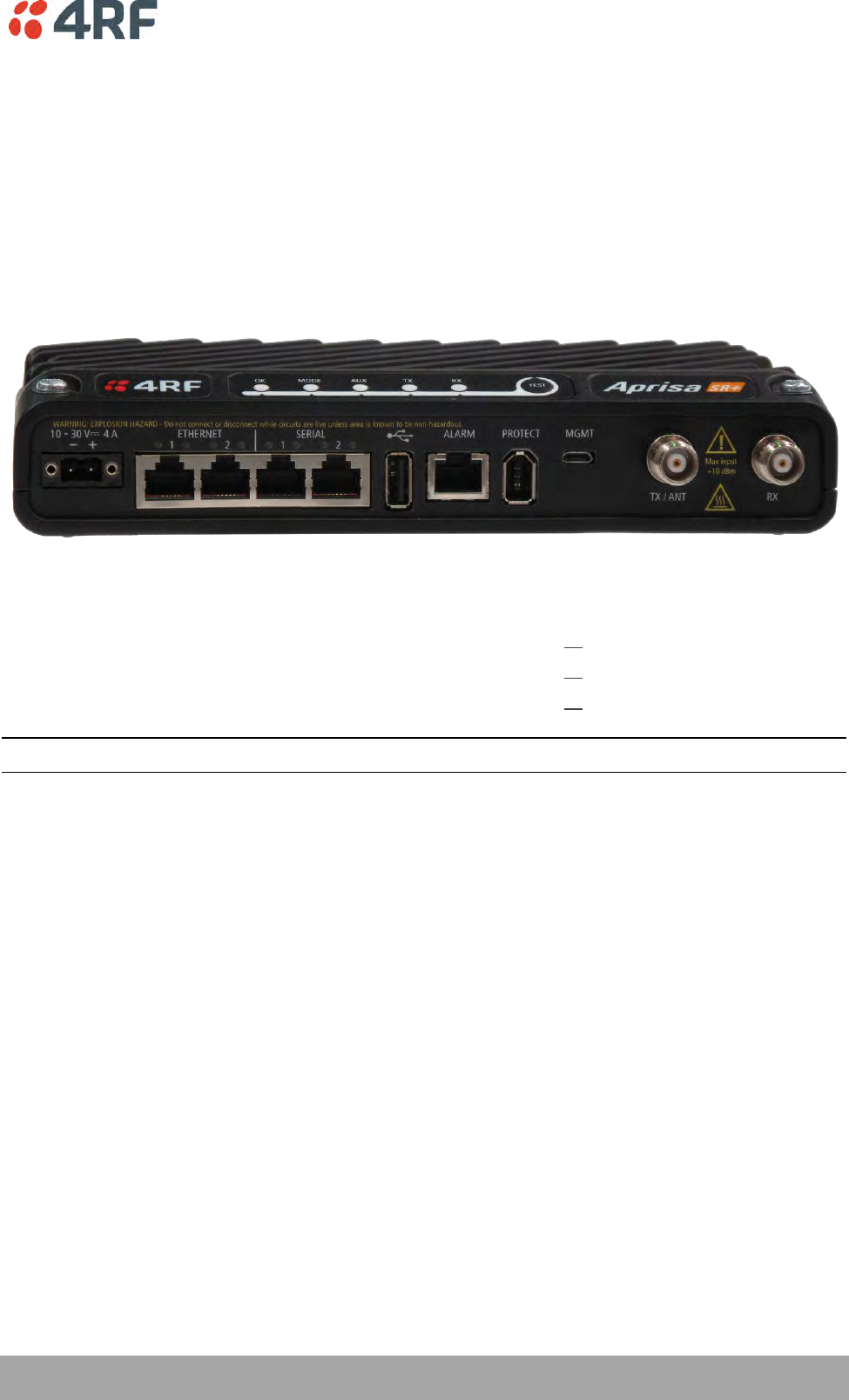
Data Interface Ports
The standard Aprisa SR+ provides multiple interface port options for combinations of Ethernet and RS-232
serial for a total of four interface ports i.e. port options of 2E2S, 3E1S or 4E0S, where E=Ethernet,
S=Serial port.
The product shown below is the two Ethernet ports plus two RS-232 serial ports.
Interface Port Option
Part Number
4 Ethernet ports and no RS-232 serial ports
APSQ-N400-SSC-HD-40-ENAA
3 Ethernet ports and 1 RS-232 serial port
APSQ-N400-SSC-HD-31-ENAA
2 Ethernet ports and 2 RS-232 serial ports
APSQ-N400-SSC-HD-22-ENAA
Note: The optional serial interface is always available via the USB to serial converter.
Full Duplex Base Station
The Aprisa SR+ supports Full Duplex base / master station hardware. This option works with half duplex
repeater / remote radios. The base / master station can transmit while simultaneously receiving from the
repeater /remote radios.
Example of a 400 MHz full duplex Aprisa SR+.
Part Number
Part Description
APSQ-N400-SSC-FD-22-ENAA
4RF SR+, BR, 400-470 MHz, SSC, Full Duplex, 2E2S, EN, STD
330 | Product Options
Aprisa SR+ User Manual 1.6.0 PO
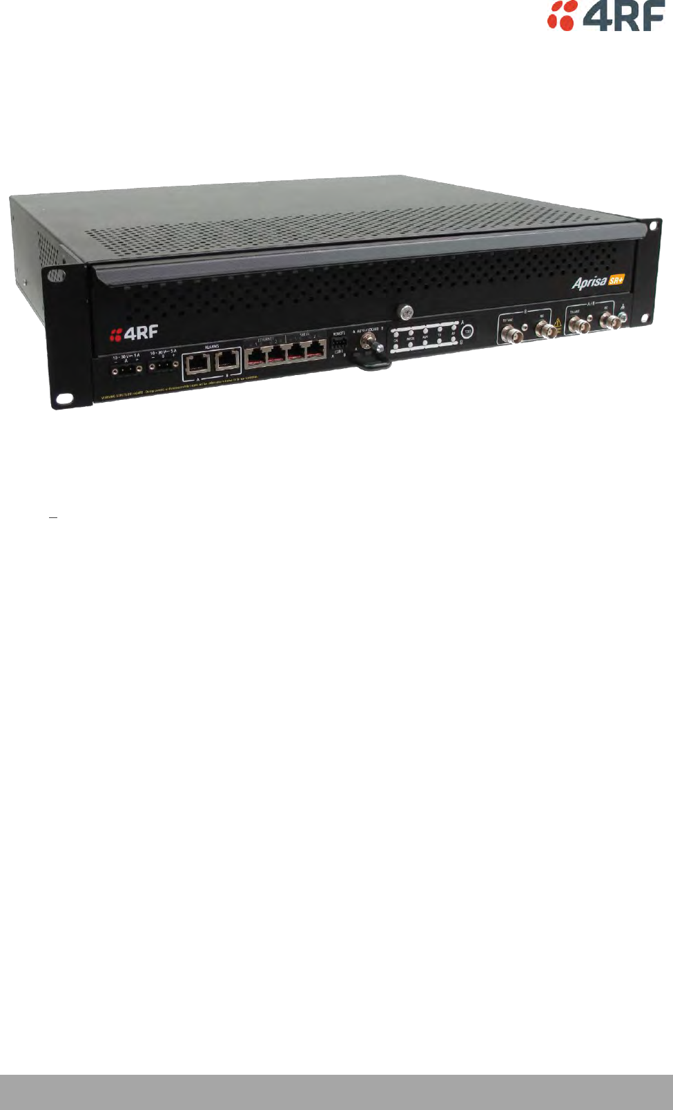
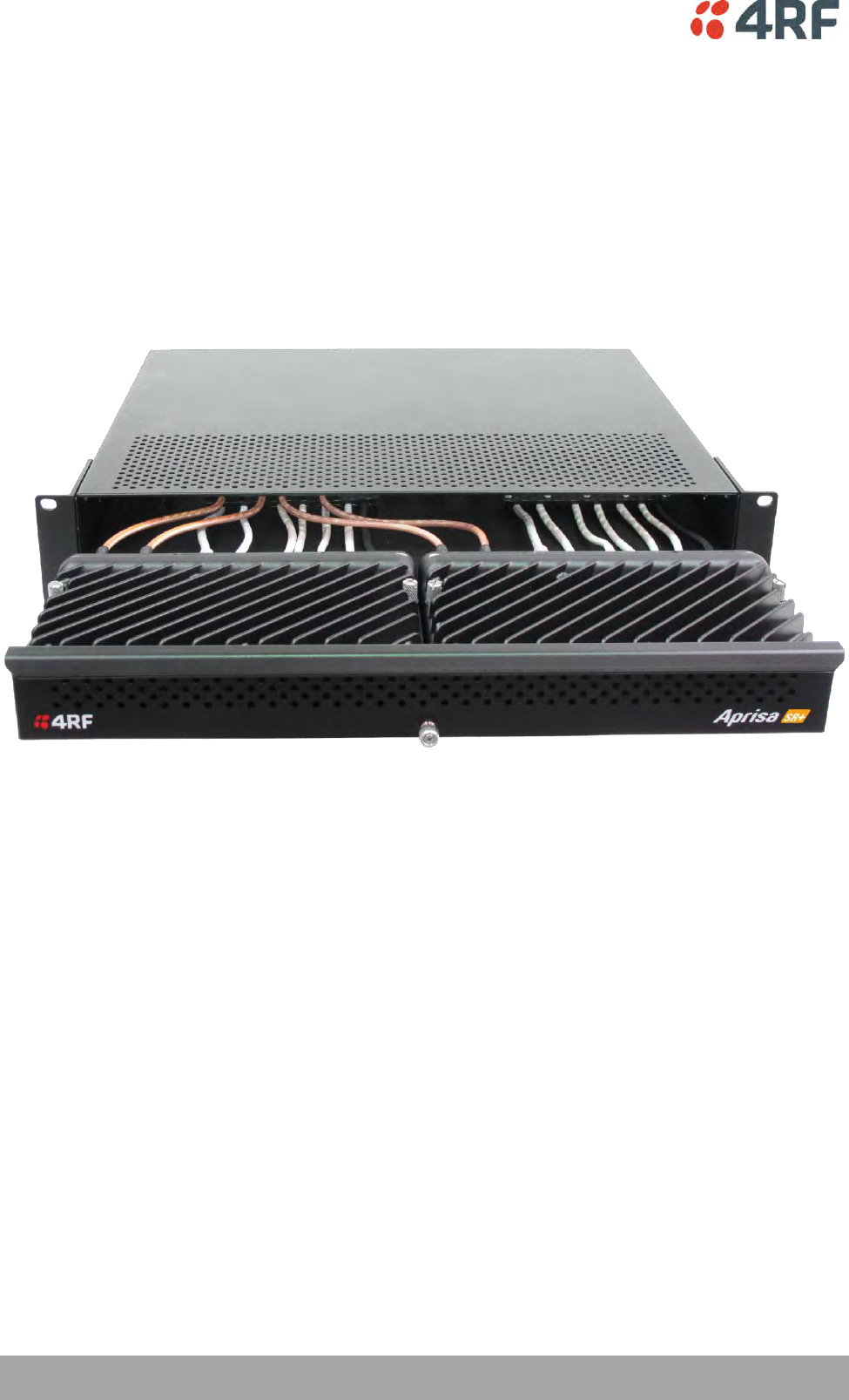
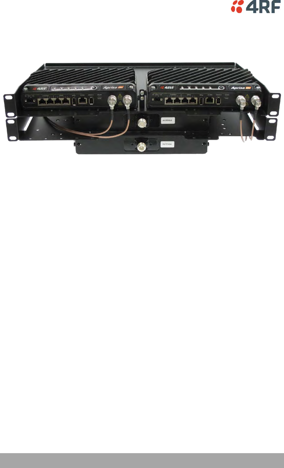
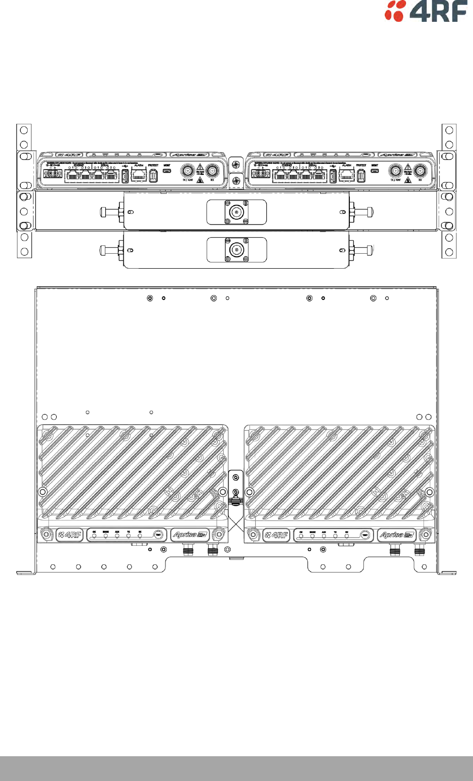
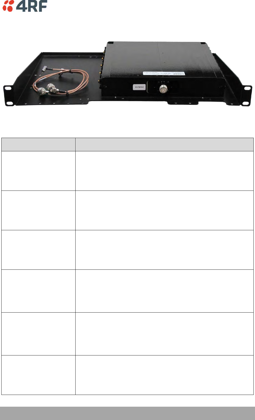
Protected Station
The Aprisa SR+ Protected Station is fully monitored hot-standby and fully hot-swappable product providing
radio and user interface protection for Aprisa SR+ radios. The RF ports and interface ports from the active
radio are switched to the standby radio if there is a failure in the active radio.
Option Example
Part Number
Part Description
APSQ-R400-SSC-HD-22-ENAA
4RF SR+, PS, 400-470 MHz, SSC, Half Duplex, 2E2S, EN, STD
The Aprisa SR+ Protected Station is comprised of an Aprisa SR+ Protection Switch and two standard Aprisa
SR+ radios mounted in a 2U rack mounting chassis.
All interfaces (RF, data, etc.) are continually monitored on both the active and standby radio to ensure
correct operation. The standby radio can be replaced without impacting traffic flow on the active radio.
The Aprisa SR+ radios can be any of the currently available Aprisa SR+ radio frequency bands, channel
sizes or interface port options.
The Aprisa SR+ Protected Station can operate as a base station, repeater station or remote station. The
protection behaviour and switching criteria between the active and standby radios is identical for the
three configurations.
By default, the Aprisa SR+ Protected Station is configured with the left hand radio (A) designated as the
primary radio and the right hand radio (B) designated as the secondary radio.
Each radio is configured with its own unique IP and MAC address and the address of the partner radio.
On power-up, the primary radio will assume the active role and the secondary radio will assume the
standby role. If, for some reason, only one radio is powered on it will automatically assume the active
role.
Both the Aprisa SR+ Protected Station primary radio and secondary radio must be operating on the same
software version.

Product Options | 331
Aprisa SR+ User Manual 1.6.0 PO
Protected Ports
The protected ports are located on the protected station front panel. Switching occurs between the active
radio ports and the standby radio ports based on the switching criteria described below.
The protected ports include:
Antenna ports ANT/TX and RX (if dual antenna ports used)
Ethernet ports (depending on interface port option purchased)
Serial ports (depending on interface port option purchased)
Operation
In hot-standby normal operation, the active radio carries all RS-232 serial and Ethernet traffic over the
radio link and the standby radio transmit is on with its transmitter connected to an internal load. Both
radios are continually monitored for correct operation including the transmitter and receiver and alarms
are raised if an event occurs.
The active radio sends regular ‘keep alive’ messages to the standby radio to indicate it is operating
correctly. In the event of a failure on the active radio, the RF link and user interface traffic is
automatically switched to the standby radio.
The failed radio can then be replaced in the field without interrupting user traffic.
Switch Over
The switch-over to the standby radio can be initiated automatically, on fault detection, or manually via
the Hardware Manual Lock switch on the Protection Switch or the Software Manual Lock from SuperVisor.
Additionally, it is possible to switch-over the radios remotely without visiting the station site, via the
remote control connector on the front of the Protection Switch.
On detection of an alarm fault the switch-over time is less than 0.5 seconds. Some alarms may take up to
30 seconds to be detected depending on the configuration options selected.
The Protection Switch has a switch guard mechanism to prevent protection switch oscillation. If a switch-
over has occurred, subsequent switch-over triggers will be blocked if the guard time has not elapsed.
The guard time starts at 20 seconds and doubles each switch-over to a maximum of 320 seconds and
halves after a period of two times the last guard time with no protection switch-overs.

332 | Product Options
Aprisa SR+ User Manual 1.6.0 PO
Switching Criteria
The Protected Station will switch-over operation from the active to the standby radio if any of the
configurable alarm events occur, or if there is a loss of the ‘keep alive’ signal from the active radio.
It is possible to configure the alarm events which will trigger the switch-over. It is also possible to prevent
an alarm event triggering a switch-over through the configuration of blocking criteria.
Any of the following alarm events can be set to trigger or prevent switching from the active radio to the
standby radio (see ‘Events > Events Setup’ on page 224).
PA current
Tx reverse power
Tx AGC
Temperature threshold
Thermal shutdown
RSSI Threshold
RX Synthesizer Not Locked
Rx CRC errors
RF no receive data
Port 1 Eth no receive data
Port 2 Eth no receive data
Port 1 Eth data receive errors
Port 2 Eth data receive errors
Port 1 Eth data transmit errors
Port 2 Eth data transmit errors
Port 3 Eth no receive data
Port 4 Eth no receive data
Port 3 Eth data receive errors
Port 4 Eth data receive errors
Port 3 Eth data transmit errors
Port 4 Eth data transmit errors
Port 1 Serial Data No RX Data
Port 2 Serial Data RX Data
Port 1 Serial Data RX Errors
Port 2 Serial Data RX Errors
USB Port Serial Data No RX Data
USB Port Serial Data RX Errors
Component failure
Calibration failure
Configuration not supported
Protection Hardware Failure
Alarm Input 1
Alarm Input 2
It will not attempt to switch-over to a standby radio which has power failure.
It will also not switch over to a standby radio with an active alarm event which has been configured as a
‘blocking criteria’.
Switch-over will be initiated once either of these conditions is rectified, i.e. power is restored or the
alarm is cleared.
Product Options | 333
Aprisa SR+ User Manual 1.6.0 PO
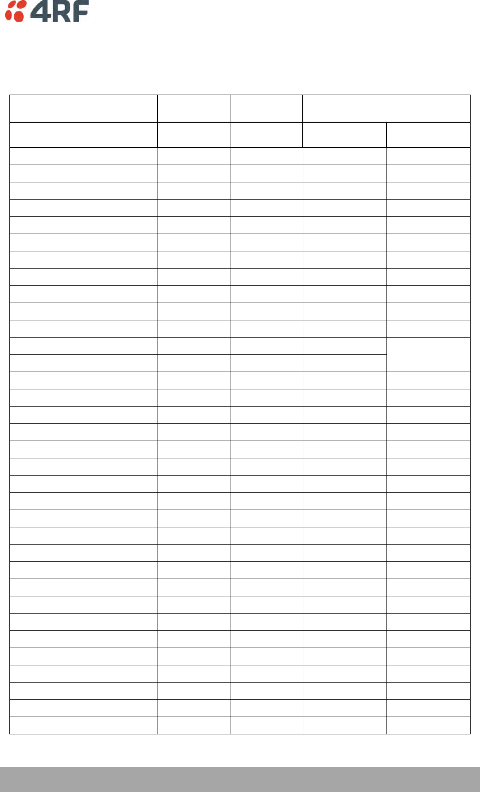
Monitored Alarms
The following alarms are monitored by default on the active / standby radio. The monitored alarms are
dependent on the Protection Type selected.
Protection Type
All Protection
Types
Redundant
Monitored Hot Standby
Alarm Type
Monitored on
Active Radio
Monitored on
Standby Radio
Monitored on
Standby Radio TX
Monitored on
Standby Radio RX
PA Current
PA Driver Current
PA Stability
TX AGC
TX Forward Power
TX Reverse Power
Temperature Threshold
TX Synthesizer Not Locked
Thermal Shutdown
RSSI Threshold
RX Synthesizer Not Locked
RX CRC Errors
RF No Receive Data
Port1 ETH No Receive Data
Port1 ETH Data Receive Errors
Port1 ETH Data Transmit Errors
Port2 ETH No Receive Data
Port2 ETH Data Receive Errors
Port2 ETH Data Transmit Errors
Port3 ETH No Receive Data
Port3 ETH Data Receive Errors
Port3 ETH Data Transmit Errors
Port4 ETH No Receive Data
Port4 ETH Data Receive Errors
Port4 ETH Data Transmit Errors
Port1 Serial Data No RX Data
Port1 Serial Data RX Errors
Port2 Serial Data No RX Data
Port2 Serial Data RX Errors
USB Port Serial Data No RX Data
USB Port Serial Data No RX Errors
Component Failure
Protection SW Manual Lock
Protection HW Manual Lock

334 | Product Options
Aprisa SR+ User Manual 1.6.0 PO
Protection Type
All Protection
Types
Redundant
Monitored Hot Standby
Alarm Type
Monitored on
Active Radio
Monitored on
Standby Radio
Monitored on
Standby Radio TX
Monitored on
Standby Radio RX
Modem FEC Disable
Modem ACM Lock
Alarm Input 1
Alarm Input 2
Protection Peer Comms Lost
Protection Hardware Failure
VDC Power Supply
3.3 Volts Power Supply
5.0 Volts Power Supply
7.2 Volts Power Supply
15.0 Volts Power Supply
Configuration Management
The Primary and Secondary radios are managed with the embedded web-based management tool,
SuperVisor, by using either the Primary or Secondary IP address. Configuration changes in one of the radios
will automatically be reflected in the partner radio.
To ensure all remote stations are registered to the correct (active) base station, changes to the Network
Table are automatically synchronized from the active radio to the standby radio. The Network Table is
only visible on the active radio. This synchronization does not occur if the Hardware Manual Lock is active.
Product Options | 335
Aprisa SR+ User Manual 1.6.0 PO
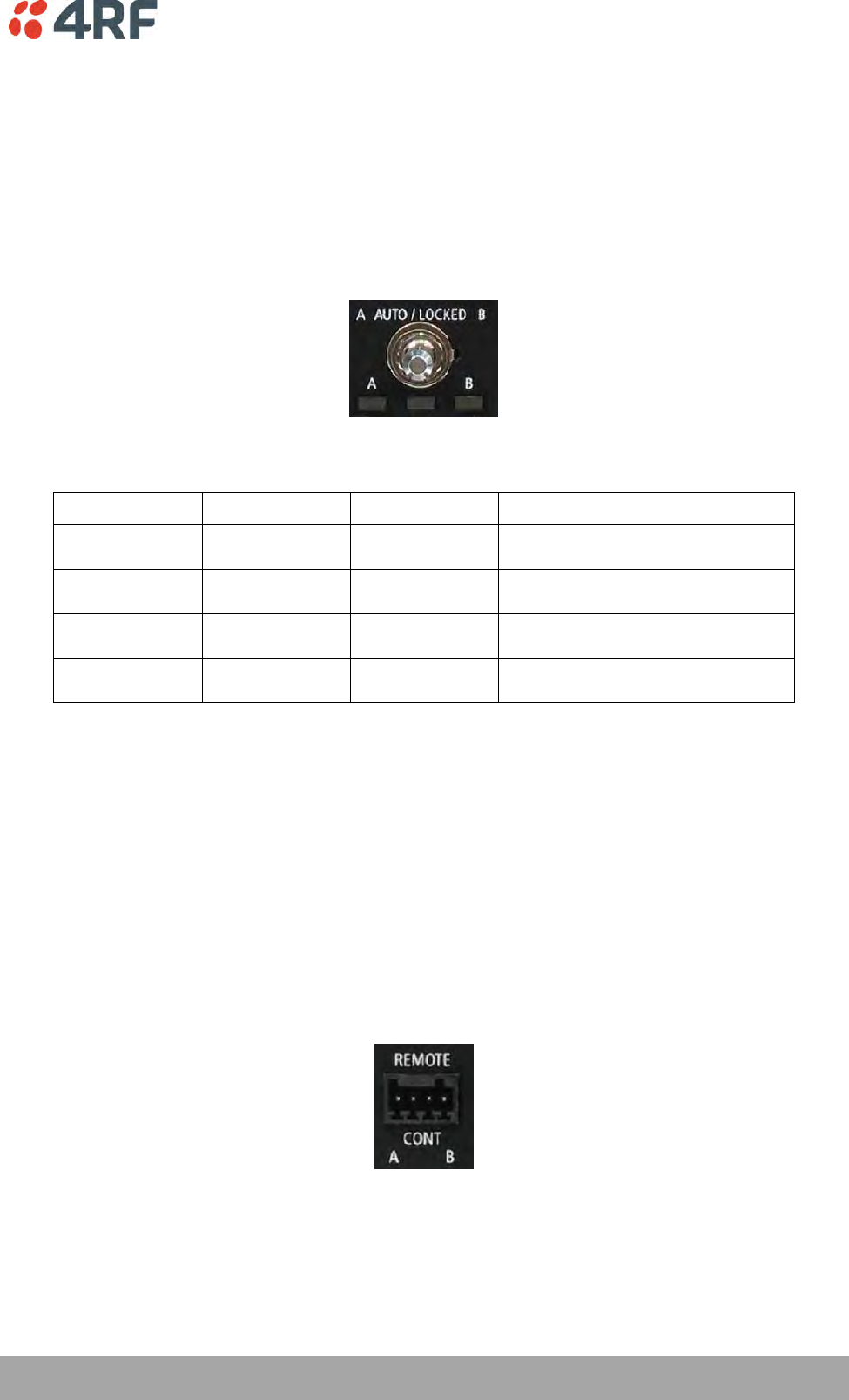
Hardware Manual Lock
The Hardware Manual Lock switch on the Protection Switch provides a manual override of the active /
standby radio.
When this lock is activated, the selected radio (A or B) becomes the active radio regardless of the
Software Manual Lock and the current switching or block criteria.
When the lock is deactivated (set to the Auto position), the protection will become automatic and
switching will be governed by normal switching and blocking criteria.
The state of the switch is indicated by the three LEDs on the Protection Switch:
A LED
B LED
Locked LED
State
Green
Off
Off
Auto - Radio A is active
Off
Green
Off
Auto - Radio B is active
Green
Off
Orange
Manual Lock to radio A
Off
Green
Orange
Manual Lock to radio B
The Protection Switch also has a Software Manual Lock. The Hardware Manual Lock takes precedence over
Software Manual Lock if both diagnostic functions are activated i.e. if the Software Manual Lock is set to
‘Primary’ and the Hardware Manual Lock set to ‘Secondary’, the system will set the Secondary radio to
Active.
When a Hardware Manual Lock is deactivated (set to the Auto position), the Software Manual Lock is re-
evaluated and locks set appropriately.
Remote Control
The switch-over to the standby radio can be initiated via the Remote Control connector on the front of the
Protection Switch. This control will only operate if the Hardware Manual Lock switch is set to the Auto
position.
The inputs are logic inputs with 4700 Ω pullup to +3.3 VDC. They require a pull down to ground to activate
the control. The ground potential is available on the connector (see ‘Protection Switch Remote Control
Connections’ on page 367).
336 | Product Options
Aprisa SR+ User Manual 1.6.0 PO
L2 / L3 Protection Operation
The Aprisa SR+ Protected Station has selectable L2 Bridge or L3 Router modes, with VLAN, QoS and L2/3/4
address filtering attributes. Each Radio is configured with its own unique IP and MAC address and partner
radio address. On switch-over failure, the new active radio sends out a gratuitous ARP to update the MAC
learning tables / ARP tables of upstream bridge/router for appropriate traffic flow.
Hot-Swappable
The two Aprisa SR+ radios are mounted on a pull-out tray to making it possible to replace a failed radio
without interrupting user traffic.
Product Options | 337
Aprisa SR+ User Manual 1.6.0 PO
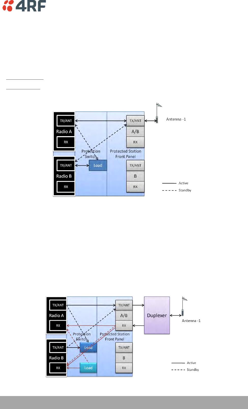
Antenna and Duplexer Options
Option 1 - single antenna without a duplexer
In this configuration, a single antenna is used and connected directly to the Aprisa SR+ Protected Station
TX/ANT (A/B side) TNC port on the front panel. In this option Protected Station can operate in:
Half duplex RF operation only
If single frequency used, standby radio TX is OFF/Mute (as RX/TX on same connector).
If dual frequency used, standby radio TX is ON, transmit to internal load for fault monitoring.
Only the active radio receives the signal (single RX path) from the antenna.
Option 2 - single antenna with a single duplexer
In this configuration, a single antenna is used with a duplexer which is connected to the Aprisa SR+
Protected Station TX/ANT and RX (A/B side) TNC ports on the front panel. In this option, the Protected
Station can operate in:
Half or full duplex RF operation
Only dual frequency supported, where standby radio TX is ON, transmits to internal load for fault
monitoring
When the ‘Protection Type’ is set to ‘monitored hot standby’ (Terminal > Operating Mode), the standby
radio RX/TX can be fault monitored. This mode has a 4 dB loss in RX sensitivity.
When the ‘Protection Type’ is set to ‘redundant’, the standby radio RX/TX will not be fault monitored.
This mode has 1 dB loss in RX sensitivity.
338 | Product Options
Aprisa SR+ User Manual 1.6.0 PO
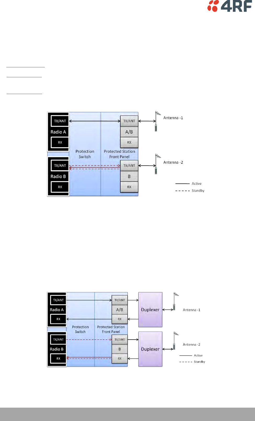
Option 3 - dual antenna without a duplexer
In this configuration, antenna redundancy is supported with dual antennas connected to the Aprisa SR+
Protected Station TX/ANT (A/B side) and TX/ANT (B side) TNC ports on the front panel. In this option, the
Protected Station can operate in:
Half duplex RF operation only
If single frequency used, standby radio RX (TX is off) can’t be monitored as it will receive the active TX.
If dual frequency used, and the ‘Protection Type’ is set to ‘monitored hot standby’ (Terminal > Operating
Mode), the standby radio RX/TX can be fault monitored. This mode has a 1 dB loss in RX sensitivity.
If dual frequency used, and the ‘Protection Type’ is set to ‘redundant’, the standby radio RX/TX will not
be fault monitored.
Option 4 - dual antenna with dual duplexers
In this configuration, antenna redundancy is supported with dual antennas connected via dual duplexers to
the Aprisa SR+ Protected Station TX/ANT and RX (A/B side) TNC ports and TX/ANT and RX (B side) TNC
ports on the front panel. In this option, the Protected Station can operate in:
Half or full duplex RF operation
Only dual frequency
When the ‘Protection Type’ is set to ‘monitored hot standby’ (Terminal > Operating Mode), the standby
radio RX/TX can be fault monitored. This mode has a 1 dB loss in RX sensitivity.
When the ‘Protection Type’ is set to ‘redundant’, the standby radio RX/TX will not be fault monitored.
Product Options | 339
Aprisa SR+ User Manual 1.6.0 PO
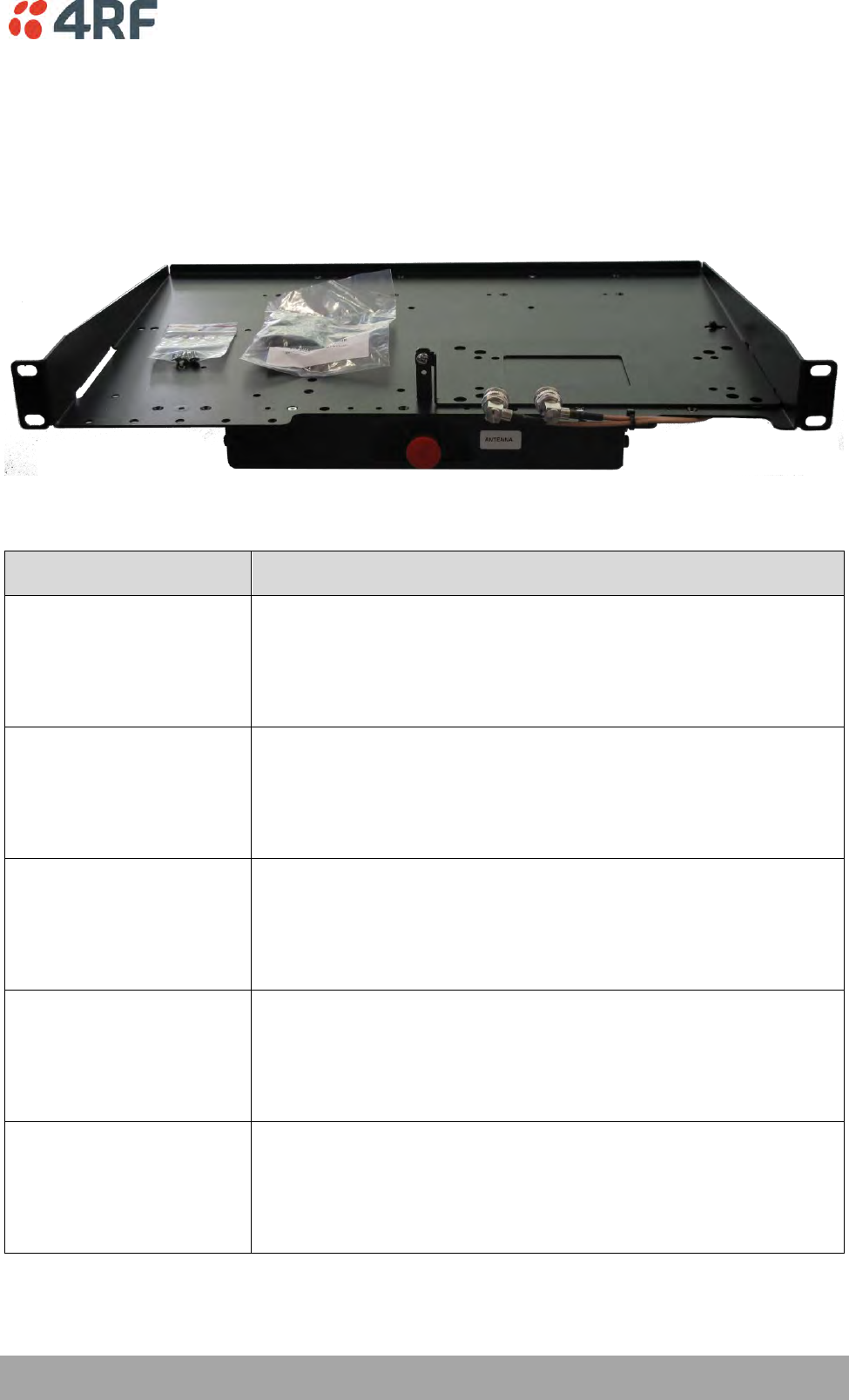
Installation
Mounting
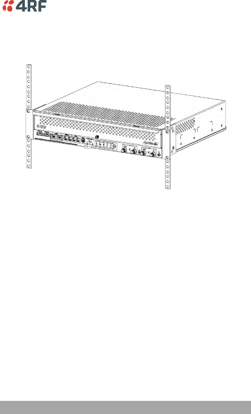
The Aprisa SR+ Protected Station is designed to mount in a standard 19 inch rack.
340 | Product Options
Aprisa SR+ User Manual 1.6.0 PO
Cabling
The Aprisa SR+ Protected Station is delivered pre-cabled with power, interface, management and RF
cables.
There are two options for the pre-cabled Protected Station (see ‘Antenna and Duplexer Options’):
1. Standard Protected Station- suitable for options #1 and #2 (single antenna operation)
Part Number
Part Description
APSQ-R400-SSC-HD-22-ENAA
4RF SR+, PS, 400-470 MHz, SSC, Half Duplex, 2E2S, EN, STD
2. Dual Antenna Protected Station- suitable for options #3 and #4 (dual antenna operation)
Part Number
Part Description
APSQ-R400-SSC-HD-22-ENDA
4RF SR+, PS, 400-470 MHz, SSC, Half Duplex, 2E2S, EN, Dual Ant
Each option (per ordered part number) is pre-cable configured as the following:
Protected Station Wiring
Internal pre-cabled Protected Station wiring setting
Radio / TNC Port
RF Switch Port
Standard Protected Station
(single antenna operation)
Radio A TX/ANT
TX/ANTA
Radio A RX
RXA
Radio B TX/ANT
TX/ANTB
Radio B RX
RXB
Dual Antenna Protected Station
(dual antenna operation)
Radio A TX/ANT
TX/ANTA
Radio A RX
RXA
Radio B TX/ANT
TXB2
Radio B RX
RXB2
Product Options | 341
Aprisa SR+ User Manual 1.6.0 PO
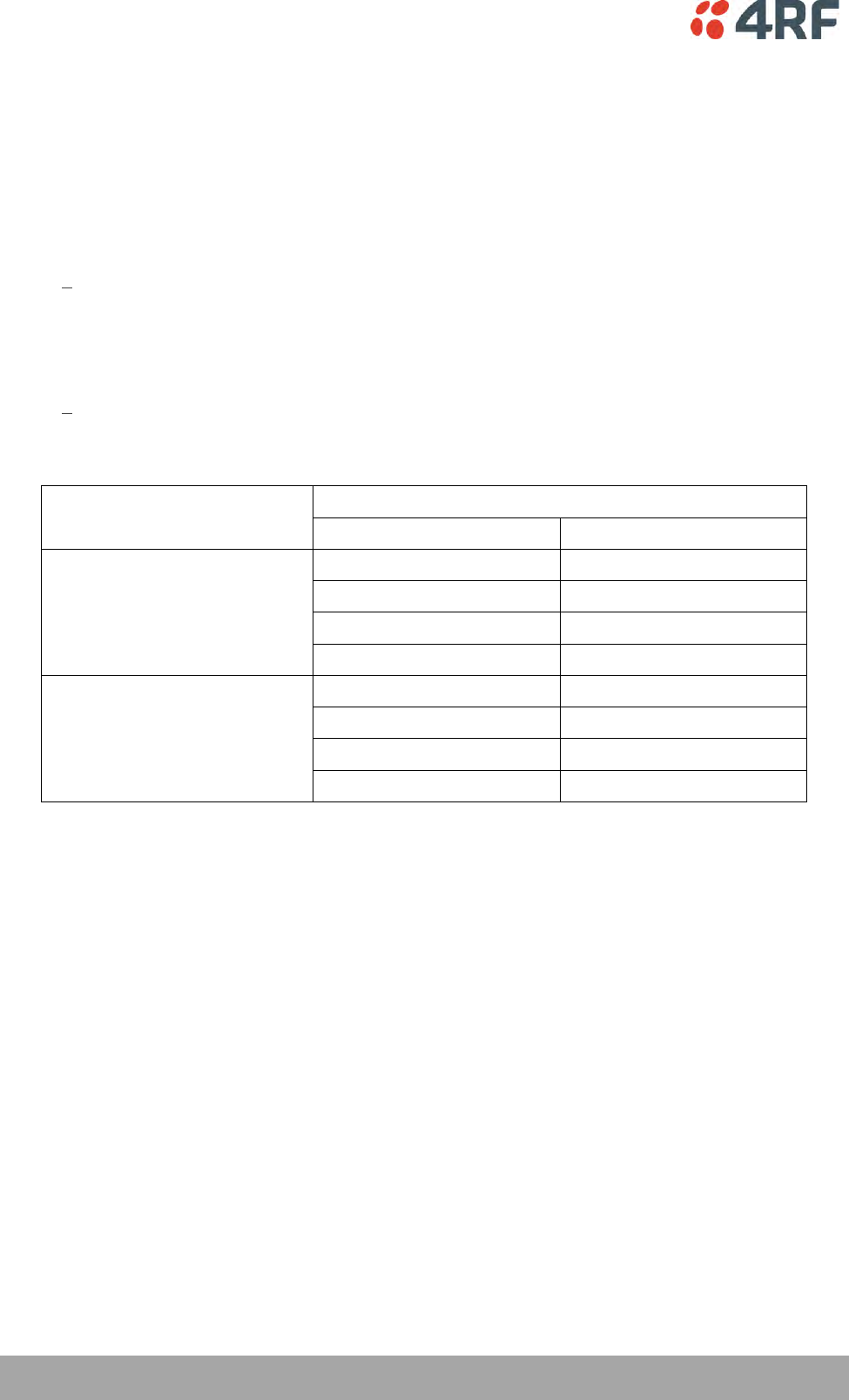
Users can change an existing Protected Station from one option to the other option by following the
procedure:
To change a pre-cabled Protected Station from one option to the other option:
1. Disconnect the power supply, antenna/s, interface cables and any other connections
2. Remove the Protected Station shelf from the rack
3. Turn the Protected Station shelf upside down
4. Remove the securing screws and remove the bottom panel
5. Unscrew the four coaxial cable clamp screws
6. Swap the two cables and position them in the appropriate connector ports
7. Refit the coaxial cable clamp and tighten the four clamp screws
8. Refit the bottom panel and tighten the two screws
9. Replace the shelf in the rack
Single Antenna Operation
Dual Antenna Operation
342 | Product Options
Aprisa SR+ User Manual 1.6.0 PO
Power
The external power source must be connected to both the A and B Molex 2 pin male power connectors
located on the protected station front panel. The A power input powers the A radio and the B power input
powers the B radio.
The protection switch is powered from the A power input or the B power input (whichever is available).
The maximum combined power consumption is 42 Watts for 10 W transmit peak power.
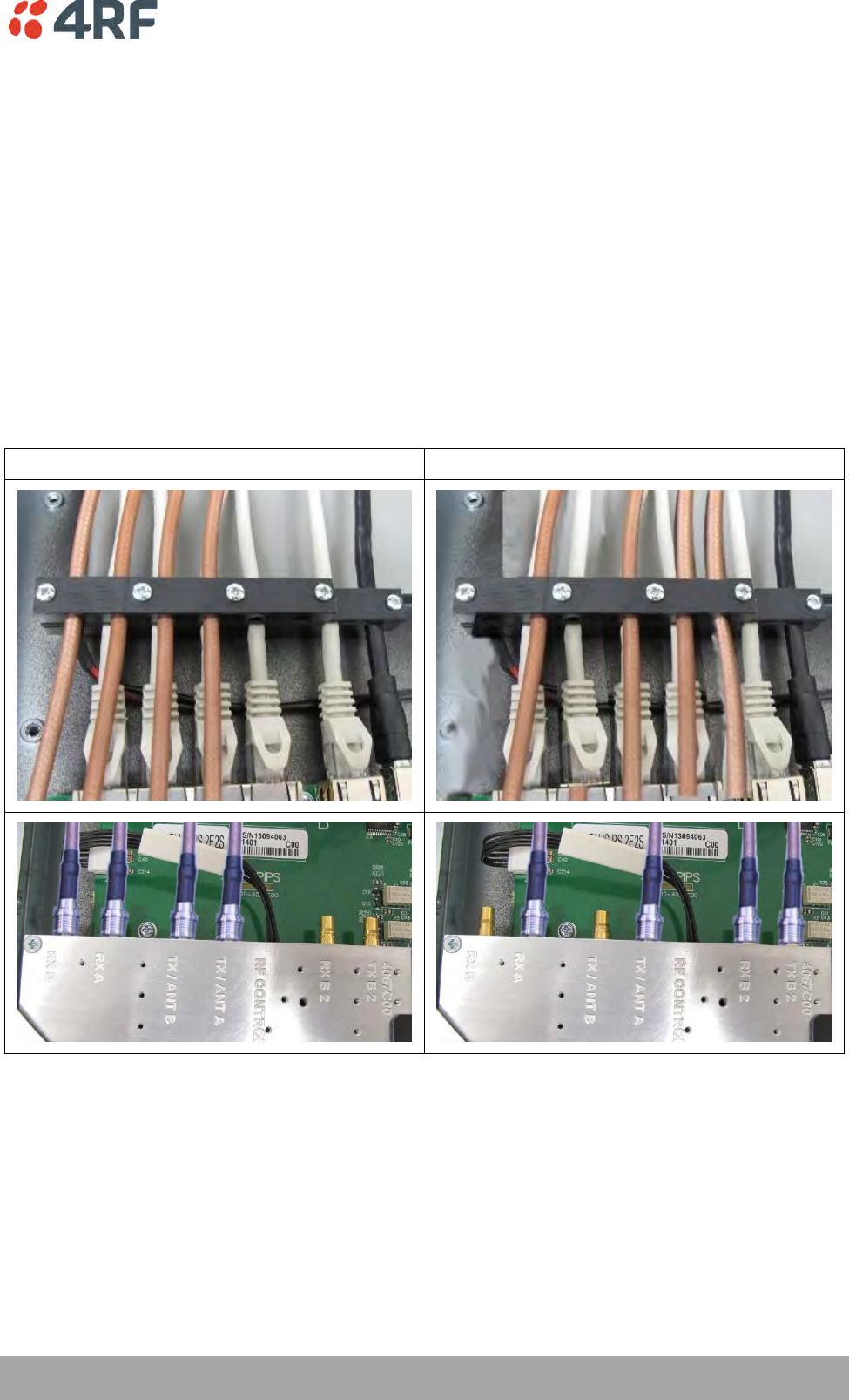
The Aprisa SR+ Protected station has two DC power options, 13.8 VDC and 48 VDC.
13.8 VDC
The 13.8 VDC nominal external power source can operate over the voltage range of +10.5 to +30 V DC
(negative earth).
An example of the 13.8 VDC option part number is:
Part Number
Part Description
APSQ-R400-SSC-HD-22-ENAA
4RF SR+, PS, 400-470 MHz, SSC, Half Duplex, 2E2S, EN, STD
48 VDC
The 48 VDC nominal external power source can operate over the voltage range of 18 to 60 V DC (floating).
An example of the 48 VDC option part number is:
Part Number
Part Description
APSQ-R400-SSC-HD-22-ENAB
4RF SR+, PS, 400-470 MHz, SSC, Half Duplex, 2E2S, EN, 48VDC
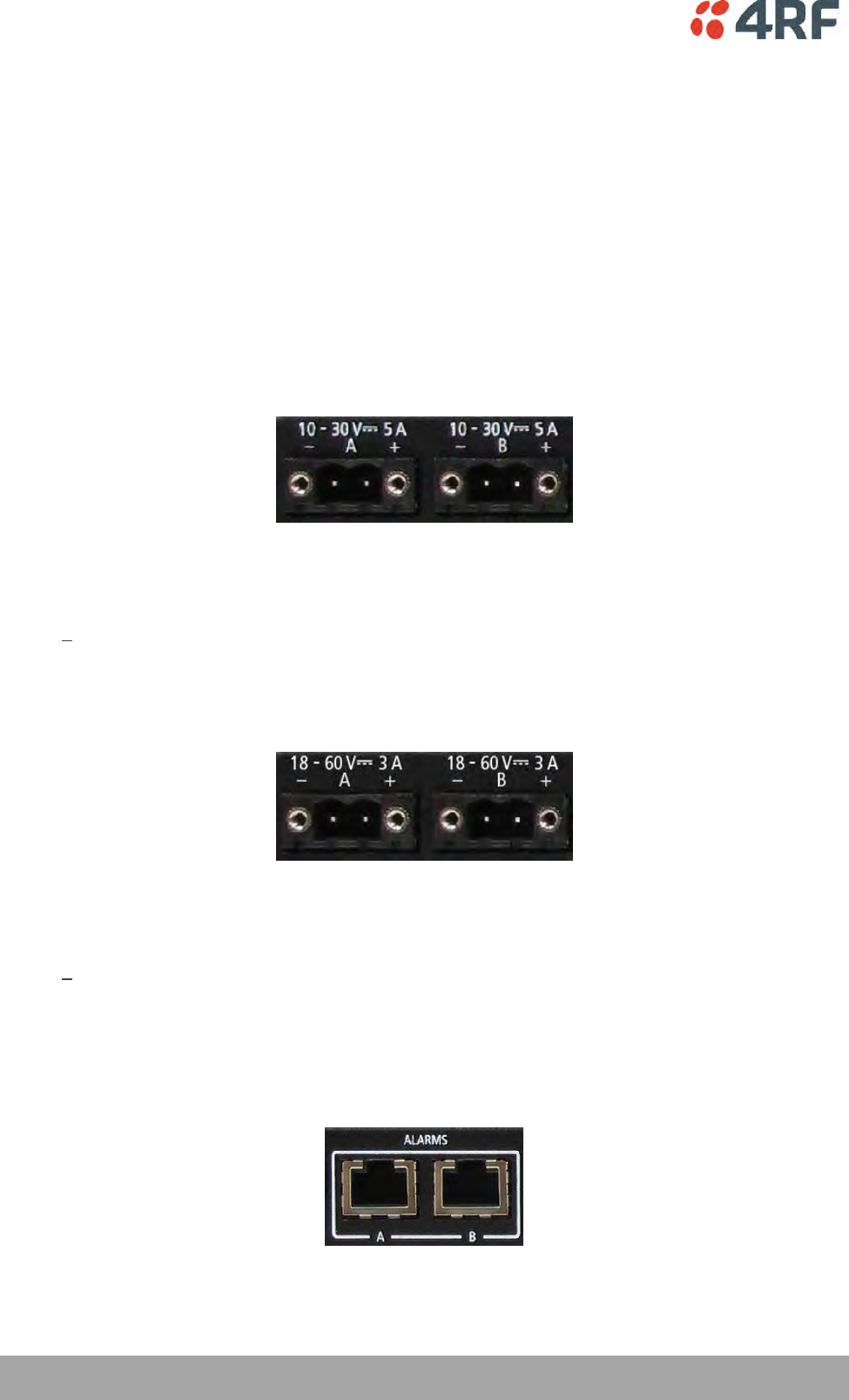
Alarms
The protection switch provides access to both the A radio and B radio Alarm Interfaces (see ‘Alarm
Interface Connections’ on page 366 for the connector pinout).

Product Options | 343
Aprisa SR+ User Manual 1.6.0 PO
Maintenance
Changing the Protected Station IP Addresses
To change the IP address of a Protected Station radio:
1. Change the IP address of either or both the Primary Radio and Secondary radio (see ‘Protected
Station: IP > IP Setup’ on page 289). Changes in these parameters are automatically changed in the
partner radio.

344 | Product Options
Aprisa SR+ User Manual 1.6.0 PO
Creating a Protected Station
When a Protected Station is ordered from 4RF, it will be delivered complete with radios installed, pre-
cabled and pre-configured for Redundant operation. The following process will not be required.
This process is to create a protected station from two individual SR+ radios and a new spare Aprisa SR+
Protection Switch. It assumes that the SR+ radios are currently setup for non-protected operation.
1. Set the protection type and partner IP address of the SR+ radio A with SuperVisor 'Terminal >
Operating Mode'. Set this radio Protection Unit to primary.
2. Set the protection type and partner IP address of the secondary SR+ radio B with SuperVisor Terminal
> Operating Mode'. Set this radio Protection Unit to secondary.
3. Switch off the radios and place the two radios in the new spare Aprisa SR+ Protection Switch.
4. Ensuring that the cables are not crossed over, plug in the interface port cables, the Alarm and Protect
port cables and the power connector to both the radios. Secure the power connectors with the two
screws.
5. Power on the Protected Station.
6. Connect to either one of the radios via SuperVisor. This will start up SuperVisor in Single Session
Management mode.
7. The user can now configure the Protected Station as required.
Replacing a Protected Station Faulty Radio
Replacing a faulty radio in a Protected Station can be achieved without disruption to traffic.
Assuming that the primary radio is active and the secondary radio is faulty and needs replacement:
1. Ensure the replacement radio has the same version of software installed as the primary radio. If
necessary, upgrade the software in the replacement radio.
2. Set the RF Interface MAC Address (see ‘Protected Station: Maintenance > Advanced’ on page 300).
This MAC address is present on chassis label.
3. Using SuperVisor > Maintenance > Advanced ‘Save Configuration to USB’ and ‘Restore Configuration
from USB’ operation, clone the primary radio’s configuration to the replacement radio.
4. Configure the replacement radio as the secondary radio and setup the IP address and other protection
parameters (see ‘Terminal > Operating Mode’ on page 94).
5. Set the Hardware Manual Lock switch to make the primary radio active.
6. Unplug the interface port cables, the Alarm and Protect port cables and the power connector from the
faulty radio being replaced. The two screws securing the power connector will need to be undone.
7. Carefully remove the faulty radio from the protection switch.
8. Install the replacement radio into the protection switch.
9. Ensuring that the cables are not crossed over, plug in the interface port cables, the Alarm and Protect
port cables and the power connector to the replacement radio. Secure the power connector with the
two screws.
10. Power on the replacement radio and wait for it to become standby.
11. Set the Hardware Manual Lock switch to the Auto position.

Product Options | 345
Aprisa SR+ User Manual 1.6.0 PO
Replacing a Faulty Power Supply
Replacing one of the power supplies can be achieved without disruption to traffic.
If a power supply has failed, the associated radio will have failed which will have caused the protection
switch to switch-over to the other radio. It will not have switched back unless the power was restored and
another problem occurred which caused a switch-over.
1. If the A power supply is faulty, ensure that the B radio is active (whether it be the primary or
secondary radio).
If the B power supply is faulty, ensure that the A radio is active (whether it be the primary or
secondary radio).
2. Replace the faulty power supply.
Replacing a Faulty Protection Switch
Note: Replacing a faulty Protection Switch will disrupt traffic.
Move the radios, the interface cables and the power cables to the replacement Protection Switch.
On both Protected Station radios:
1. Power on the radio and wait for it to become ready.
2. Using SuperVisor > Maintenance > Advanced, enter the RF Interface MAC address shown on the
Protection Switch label (see ‘Protected Station: Maintenance > Advanced’ on page 300).
3. Using SuperVisor > Maintenance > Advanced, Decommission the node (see ‘Decommission Node’ on
page 218) and then Discover the Nodes (see ‘Discover Nodes’ on page 218).
Ensure that the Hardware Manual Lock switch is set to the Auto position.
The Aprisa SR+ Protected Station is now ready to operate.
Spares
The Aprisa SR+ Protection Switch is available as spare parts for the three radio interface port options:
Part Number
Part Description
APST-XPSW-X22
4RF SR+ Spare, Protection Switch, 2E2S
APST-XPSW-X31
4RF SR+ Spare, Protection Switch, 3E1S
APST-XPSW-X40
4RF SR+ Spare, Protection Switch, 4E0S
346 | Product Options
Aprisa SR+ User Manual 1.6.0 PO
Data Driven Protected Station
The Aprisa SR+ Data Driven Protected Station provides radio and RS-232 serial port user interface
protection for Aprisa SR+ radios.
Example Part:
Part Number
Part Description
APSQ-D400-SSC-HD-22-ENAA
4RF SR+, PD, 400-470 MHz, SSC, Half Dup, 2E2S, EN, STD
The Aprisa SR+ Data Driven Protected Station shown is comprised of two standard Aprisa SR+ setup as
‘dual antenna port’, ‘half duplex’ radios and two external duplexers mounted on 19" rack mounting
shelves.
The Aprisa SR+ radios can be any of the currently available Aprisa SR+ radio frequency band options.
By default, the Aprisa SR+ Data Driven Protected Station is configured with the left hand radio (A)
designated as the primary radio and the right hand radio (B) designated as the secondary radio.
Each radio is configured with its own unique IP and MAC address and the address of the partner radio.
On power-up, the primary radio will assume the active role and the secondary radio will assume the
standby role. If, for some reason, only one radio is powered on it will automatically assume the active
role.
Operation
The active radio is determined explicitly by which radio receives data on its RS-232 serial port input from
the interface.
The active radio carries all RS-232 serial traffic over its radio link and the standby radio is unused with its
transmitter turned off.
If data is received on the RS-232 serial port interface input of the standby radio, it will immediately
become the active radio and the radio which was active will become the standby radio.
Over The Air Compatibility
If the Aprisa SR+ Data Driven Protected Station is to be used in a network of New Aprisa SR radios, the ‘SR
Compatible’ option must be enabled (see ‘SR Compatible’ on page 95).

Product Options | 347
Aprisa SR+ User Manual 1.6.0 PO
Switch Over
The active radio is determined explicitly by which radio receives data on its RS-232 serial port.
The switching and blocking criteria used for the standard Protected Station do not apply. This means that
events and alarms on the unit are not used as switching criteria.
Configuration Management
The Primary and Secondary radios are managed with the embedded web-based management tool,
SuperVisor (see ‘Managing the Radio’ on page 67) by using either the Primary or Secondary IP address.
Configuration changes in one of the radios will automatically be reflected in the partner radio.
Changes to the Network Table are automatically synchronized from the active radio to the standby radio
but the Network Table is only visible on the active radio.
Power
A +10.5 to +30 V DC external power source must be connected to both the A and B Phoenix Contact 2 pin
male power connectors. The maximum combined power consumption is 42 Watts for 10 W transmit peak
power.
348 | Product Options
Aprisa SR+ User Manual 1.6.0 PO
Installation
Mounting
The Aprisa SR+ Data Driven Protected Station is designed to mount in a standard 19” rack on two 1U rack
mounting shelves (total of 3RU).
Cabling
The Aprisa SR+ Data Driven Protected Station is delivered with the radios, duplexers, rack mounting
shelves and interconnect cables. The set of interconnect cables is available as a spare part.
Part Number
Part Description
APST-XPSC-ST6
4RF SR+ Spare, Protection Switch Cables, Set Of 6
Product Options | 349
Aprisa SR+ User Manual 1.6.0 PO
Duplexer Kits
The Aprisa SR+ product range contains Duplexer Kit accessories for use with Aprisa SR+ radios configured
for Single Antenna Dual Port operation.
Radio Duplexer Kits
Example of part number: APSB-KDUP-400-B1-BR
Part Number
Description
APSB-KDUP-135-N0-BR
Aprisa SR+ Duplexer Kit for a SR+ Radio containing:
1x 1U 19" rack front mount shelf with duplexer mounting brackets and
screws to mount 1x SR+ radio and 1x duplexer
1x N0 Duplexer 135 MHz, s4.6 MHz, p0.5 MHz
2x TNC to SMA right angle 640mm cables
APSB-KDUP-320-A1-BR
Aprisa SR+ Duplexer Kit for a Aprisa SR+ radio containing:
1x 1U 19" rack front mount shelf with duplexer mounting brackets and
screws to mount 1x SR+ radio and 1x duplexer
1x A1 Duplexer 300 MHz, s 5 MHz, p 0.5 MHz
2x TNC to SMA right angle 640mm cables
APSB-KDUP-400-B1-BR
Aprisa SR+ Duplexer Kit for a SR+ Radio containing:
1x 1U 19" rack front mount shelf with duplexer mounting brackets and
screws to mount 1x SR+ radio and 1x duplexer
1x B1 Duplexer 400 MHz, s 5 MHz, p 0.5 MHz
2x TNC to SMA right angle 640mm cables
APSB-KDUP-450-M0-BR
Aprisa SR+ Duplexer Kit for a SR+ radio containing:
1x 1U 19" rack front mount shelf with duplexer mounting brackets and
screws to mount 1x SR+ radio and 1x duplexer
1x M0 Duplexer 450 MHz, s 5 MHz, p 0.5 MHz
2x TNC to SMA right angle 640mm cables
APSB-KDUP-450-P0-BR
Aprisa SR+ Duplexer Kit for a SR+ radio containing:
1x 1U 19" rack front mount shelf with duplexer mounting brackets and
screws to mount 1 or 2 Aprisa SR+ radios and 1 duplexer
1x P0 Duplexer 450 MHz, s 3 MHz, p 0.5 MHz
2x TNC to SMA right angle 640mm cab
350 | Product Options
Aprisa SR+ User Manual 1.6.0 PO
Part Number
Description
APSB-KDUP-928-G0-BR
Aprisa SR+ Duplexer Kit for a SR+ radio containing:
1x 1U 19" rack front mount shelf with duplexer mounting brackets and
screws to mount 1x SR+ radio and 1x duplexer
1x G0 Duplexer 900 MHz, s 40 MHz, p 7 MHz
2x TNC to SMA right angle 640mm cables
APSB-KDUP-928-G2-BR-MM
Aprisa SR+ Duplexer Kit for a SR+ radio containing:
1x 1U 19" rack mid mount shelf with duplexer mounting brackets and
screws to mount 1x SR+ radio and 1x duplexer
1x G2 Duplexer 900 MHz, s 9 MHz, p 1 MHz
2x TNC to SMA right angle 640mm cables
APSB-KDUP-928-G2-BR
Aprisa SR+ Duplexer Kit for a SR+ radio containing:
1x 1U 19" rack front mount shelf with duplexer mounting brackets and
screws to mount 1x SR+ radio and 1x duplexer
1x G2 Duplexer 900 MHz, s 9 MHz, p 1 MHz
2x TNC to SMA right angle 640mm cables
APSB-KDUP-928-G3-BR
Aprisa SR+ Duplexer Kit for a SR+ radio containing:
1x 1U 19" rack front mount shelf with duplexer mounting brackets and
screws to mount 1x SR+ radio and 1x duplexer
1x G3 Duplexer 900 MHz, s5.5 MHz, p0.5 MHz
2x TNC to SMA right angle 640mm cables
APSB-KDUP-928-G3-BR-MM
Aprisa SR+ Duplexer Kit for a SR+ radio containing:
1x 1U 19" rack mid mount shelf with duplexer mounting brackets and
screws to mount 1x SR+ radio and 1x duplexer
1x G3 Duplexer 900 MHz, s5.5 MHz, p0.5 MHz
2x TNC to SMA right angle 640mm cables
Product Options | 351
Aprisa SR+ User Manual 1.6.0 PO
Protected Station Duplexer Kits
Example of part number: APSB-KDUP-928-G2-PS
Part Number
Description
APSB-KDUP-135-N0-PS
Aprisa SR+ Duplexer Kit for a SR+ Protected Station containing:
1x N0 Duplexer 135 MHz, s4.6 MHz, p0.5 MHz
2x right angle TNC to SMA right angle 640mm cables
Rack front mounted
APSB-KDUP-135-N0-PS-DA
Aprisa SR+ Duplexer Kit for a dual antenna SR+ Protected Station
containing:
2x N0 Duplexer 135 MHz, s4.6 MHz, p0.5 MHz
4x right angle TNC to SMA right angle 640mm cables
Rack front mounted
APSB-KDUP-320-A1-PS
Aprisa SR+ Duplexer Kit for a Aprisa SR+ Protected Station containing:
1x 1U 19" rack front mount shelf with duplexer mounting brackets and
screws
1x A1 Duplexer 300 MHz, s 5 MHz, p 0.5 MHz
2x right angle TNC to SMA right angle 640mm cables
APSB-KDUP-320-A1-PS-DA
Aprisa SR+ Duplexer Kit for a dual antenna Aprisa SR+ Protected Station
containing:
1x 1U 19" rack front mount shelf with duplexer mounting brackets and
screws
2x A1 Duplexer 300 MHz, s 5 MHz, p 0.5 MHz
4x right angle TNC to SMA right angle 640mm cables
APSB-KDUP-400-B1-PS-DA
Aprisa SR+ Duplexer Kit for a dual antenna SR+ Protected Station
containing:
1x 1U 19" rack front mount shelf with duplexer mounting brackets and
screws
2x B1 Duplexers 400 MHz, s 5 MHz, p 0.5 MHz
4x right angle TNC to SMA right angle 640mm cables
APSB-KDUP-400-B1-PS
Aprisa SR+ Duplexer Kit for a SR+ Protected Station containing:
1x 1U 19" rack front mount shelf with duplexer mounting brackets and
screws
1x B1 Duplexer 400 MHz, s 5 MHz, p 0.5 MHz
2x right angle TNC to SMA right angle 640mm cables
352 | Product Options
Aprisa SR+ User Manual 1.6.0 PO
Part Number
Description
APSB-KDUP-450-M0-PS
Aprisa SR+ Duplexer Kit for a SR+ Protected Station containing:
1x 1U 19" rack front mount shelf with duplexer mounting brackets and
screws
1x M0 Duplexer 450 MHz, s 5 MHz, p 0.5 MHz
2x right angle TNC to SMA right angle 640mm cables
APSB-KDUP-450-M0-PS-DA
Aprisa SR+ Duplexer Kit for a dual antenna SR+ Protected Station
containing:
1x 1U 19" rack front mount shelf with duplexer mounting brackets and
screws
2x M0 Duplexer 450 MHz, s 5 MHz, p 0.5 MHz
4x right angle TNC to SMA right angle 640mm cables
APSB-KDUP-450-P0-PS
Aprisa SR+ Duplexer Kit for a SR+ Protected Station containing:
1x 1U 19" rack front mount shelf with duplexer mounting brackets and
screws
1x P0 Duplexer 450 MHz, s 3 MHz, p 0.5 MHz
2x right angle TNC to SMA right angle 640mm cables
APSB-KDUP-450-P0-PS-DA
Aprisa SR+ Duplexer Kit for a dual antenna SR+ Protected Station
containing:
1x 1U 19" rack front mount shelf with duplexer mounting brackets and
screws
2x P0 Duplexer 450 MHz, s 3 MHz, p 0.5 MHz
4x right angle TNC to SMA right angle 640mm cables
APSB-KDUP-928-G0-PS
Aprisa SR+ Duplexer Kit for a SR+ Protected Station containing:
1x 1U 19" rack front mount shelf with duplexer mounting brackets and
screws
1x G0 Duplexer 900 MHz, s 40 MHz, p 7 MHz
2x TNC to SMA right angle 590mm cables
APSB-KDUP-928-G2-PS
Aprisa SR+ Duplexer Kit for a SR+ Protected Station containing:
1x 1U 19" rack front mount shelf with duplexer mounting brackets and
screws
1x G2 Duplexer 900 MHz, s 9 MHz, p 1 MHz
2x TNC to SMA right angle 590mm cables
APSB-KDUP-928-G2-PS-MM
Aprisa SR+ Duplexer Kit for a SR+ Protected Station containing:
1x 1U 19" rack mid mount shelf with duplexer mounting brackets and
screws
1x G2 Duplexer 900 MHz, s 9 MHz, p 1 MHz
2x TNC to SMA right angle 590mm cables
APSB-KDUP-928-G3-PS-MM
Aprisa SR+ Duplexer Kit for a SR+ Protected Station containing:
1x 2U 19" rack mid mount shelf with duplexer mounting brackets and
screws
1x G3 Duplexer 900 MHz, s5.5 MHz, p0.5 MHz
2x TNC to SMA right angle 640mm cables
APSB-KDUP-928-G3-PS
Aprisa SR+ Duplexer Kit for a SR+ Protected Station containing:
1x 2U 19" rack front mount shelf with duplexer mounting brackets and
screws
1x G3 Duplexer 900 MHz, s5.5 MHz, p0.5 MHz
2x TNC to SMA right angle 640mm cables
Product Options | 353
Aprisa SR+ User Manual 1.6.0 PO
USB RS-232 / RS-485 Serial Port
The Aprisa SR+ USB host port is predominantly used for software upgrade and diagnostic reporting.
However, it can also be used to provide an additional RS-232 DCE or RS-485 serial port for customer
traffic.
This is accomplished with a USB to RS-232 / RS-485 serial converter cable. This plugs into the USB host
port connector and can be terminated with the required customer connector.
This additional RS-232 / RS-485serial port is enabled with the SuperVisor mode setting in Serial Port
Settings (see ‘Serial > Port Setup’ on page 124).
The Aprisa SR+ USB port has driver support for these USB serial converters. Other USB serial converters
may not operate correctly.
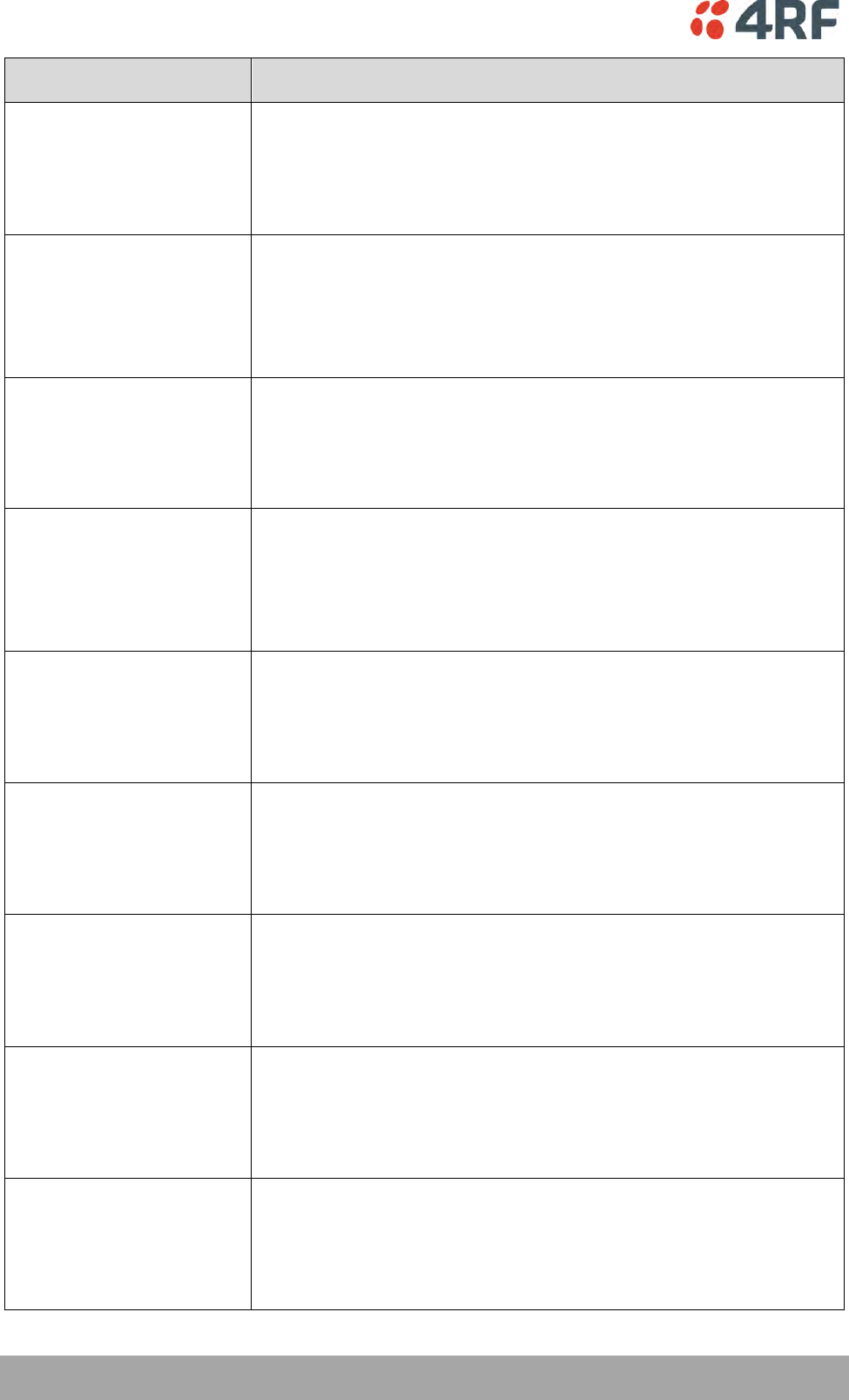
USB RS-232 / RS-485 operation
The USB serial converter buffers the received data frames into 64 byte blocks separated by a small inter-
frame gap.
For the majority of applications, this fragmentation of egress frames is not an issue. However, there are
some applications that may be sensitive to the inter-frame gap, therefore, these applications need
consideration.
A 5 ms inter-frame is recommended for the applications that are sensitive to inter-frame gap timings.
On a USB RS-232 port, Modbus RTU can operate up to 9600 bit/s with all packet sizes and up to 115200
bit/s if the packet size is less than 64 bytes. The standard RS-232 port is fully compatible with Modbus RTU
at all baud rates.
354 | Product Options
Aprisa SR+ User Manual 1.6.0 PO
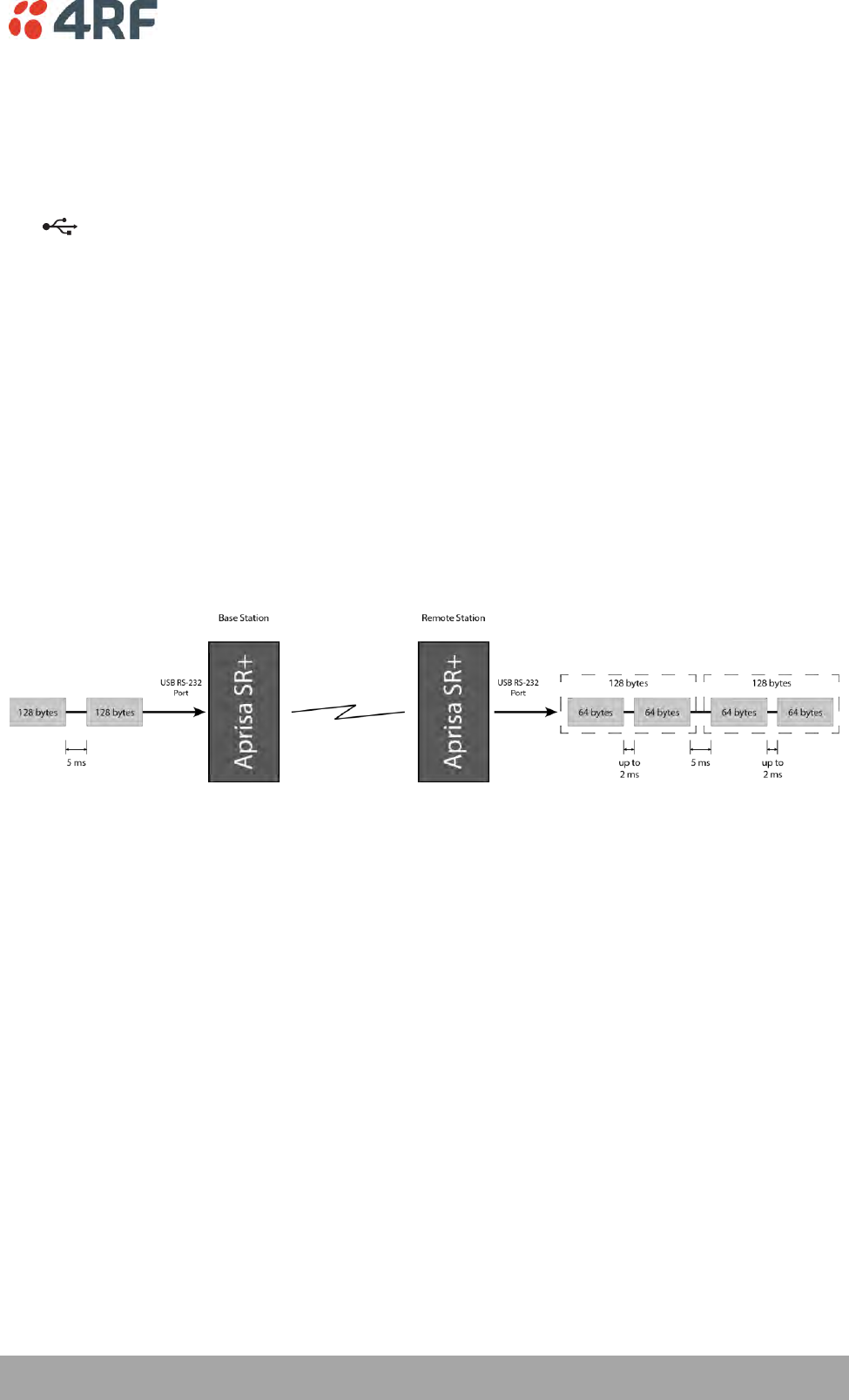
USB RS-232 Cabling Options
The following converter cables are available as Aprisa SR+ accessories to provide the customer interface.
The kit contains a USB connector retention clip (see ‘USB Retention Clip’ on page 355).
1. USB Converter to 1.8 metre multi-strand cable 6 wire for termination of customer connector
Part Number
Part Description
APSB-KFCA-USB-23-MS-18
4RF SR+ Acc, Kit, Interface, USB Conv, RS-232, Multi-strand, 1.8m
2. USB converter to RJ45 female kit for USB to RS-232 DCE conversion.
Part Number
Part Description
APSB-KFCA-USB-23-45-MF18
4RF SR+ Acc, Kit, Interface, USB Conv, RS-232, RJ45, Female, 1.8m
3. USB converter to DB9 female kit for USB to RS-232 DCE conversion.
Part Number
Part Description
APSB-KFCA-USB-23-D9-MF18
4RF SR+ Acc, Kit, Interface, USB Conv, RS-232, DB9, Female, 1.8m
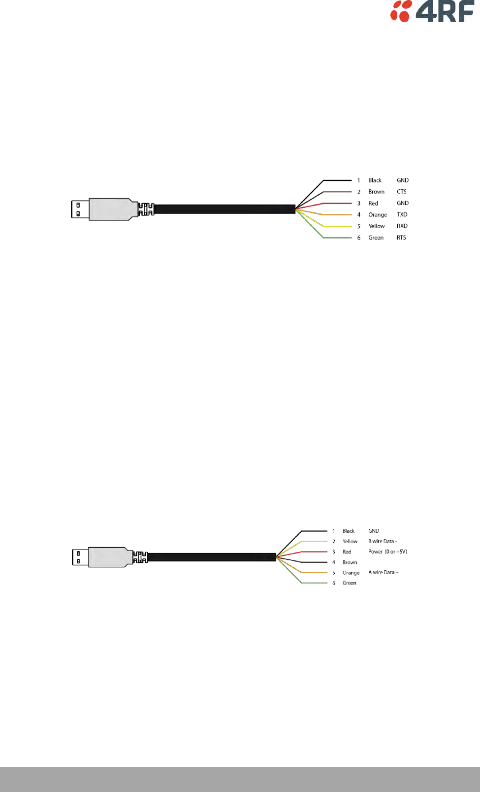
USB RS-485 Cabling Options
The following converter cable is available as an Aprisa SR+ accessory to provide the customer interface RS-
485 2 wire. The kit contains a USB connector retention clip (see ‘USB Retention Clip’ on page 355).
1. USB Converter to 1.8 metre multi-strand cable 6 wire for termination of customer interface
Part Number
Part Description
APSB-KFCA-USB-48-MS-18
4RF SR+ Acc, Kit, Interface, USB Conv, RS-485, Multi-strand, 1.8m
Product Options | 355
Aprisa SR+ User Manual 1.6.0 PO
USB Retention Clip
The USB Retention Clip attaches to the underside of the Aprisa SR+ enclosure adjacent to the USB
connector.
To attach the USB Retention Clip:
1. Clean the enclosure surface where the retention clip will attach with an alcohol based cleaner e.g.
Isopropanol.
2. Peel off the retention clip protective backing.
3. Stick the clip onto the Aprisa SR+ enclosure ensuring that it aligns to the middle of the radio USB
connector.

Maintenance | 357
Aprisa SR+ User Manual 1.6.0 PO
10. Maintenance
No User-Serviceable Components
There are no user-serviceable components within the radio.
All hardware maintenance must be completed by 4RF or an authorized service centre.
Do not attempt to carry out repairs to any boards or parts.
Return all faulty radios to 4RF or an authorized service centre.
For more information on maintenance and training, please contact 4RF Customer Services at
support@4rf.com.
CAUTION: Electro Static Discharge (ESD) can damage or destroy the sensitive electrical components in the
radio.

358 | Maintenance
Aprisa SR+ User Manual 1.6.0 PO
Software Upgrade
A software upgrade can be performed on a single Aprisa SR+ radio or an entire Aprisa SR+ network.
Network Software Upgrade
This process allows customers to upgrade their Aprisa SR+ network from the central base station location
without need for visiting remote sites.
The Software Pack is loaded into the base station with the file transfer process (see ‘Software > File
Transfer’ on page 238) and distributed via the radio link to all remote stations.
When all remote stations receive the Software Pack version, the software can be remotely activated on all
remote stations.
Non-Protected Network Upgrade Process
This upgrade process is for upgrading the software on an entire Aprisa SR+ network from a non-protected
base station. If there are protected remotes in the network, they must be locked to the current active
radio.
To upgrade the entire Aprisa SR+ network software:
1. Using File Transfer, load the software pack into the base station (see ‘Software > File Transfer’ on
page 238). The software can be transferred to the radio via an FTP transfer or from a USB flash drive.
The Aprisa SR+ network file transfer operation is indicated in base station and remote stations by a
flashing orange AUX LED.
2. Distribute the software to the entire network of remote radios (see ‘Software > Remote Distribution’
on page 246). Note that the distribution process over the air will take some time, depending on RF
and Transfer rate settings.
The Aprisa SR+ network software distribution operation is indicated in base station and remote
stations by a flashing orange MODE LED.
Note: The distribution of software to remote stations does not stop customer traffic from being
transferred. However, due to the volume of traffic, the software distribution process may affect
customer traffic.
Software distribution traffic is classified as ‘management traffic’ but does not use the Ethernet
management priority setting. Software distribution traffic priority has a fixed priority setting of ‘very
low’.
3. Activate the software on the entire network of remote radios (see ‘Software > Remote Activation’ on
page 248).
Note: When the new software activates on the remote radios, all link communication from the base
station to the remote will be lost. The base station will attempt to re-establish connectivity to the
remote radios for the new version verification but this will fail. However, when the new software
activates on the remote radios, the remote radio will reboot automatically and link communication
will restore when the base station software is activated.
When the Remote Activation process gets to the ‘Remote Radios On New Version’ step, don’t wait for
this to complete but proceed to step 4.

Maintenance | 359
Aprisa SR+ User Manual 1.6.0 PO
4. Activate the software on the base station radio (see ‘Software > Manager’ on page 242).
5. When the new software has been activated, remote stations will re-register with the base station. The
remote stations software version can verified with ‘Network Status > Network Table’ on page 271.
6. When the base station restarts with the new software, rediscover the nodes (see ‘Discover Nodes’ on
page 218).
7. Check that all remote radios are now running on the new software (see ‘Network Status > Network
Table’ on page 271).
Note: The following steps will only be necessary if for some reason steps 1-7 did not operate correctly
or if software activation is attempted before the distribution process ends or the remote radio was off
during steps 1-7 and turns on later. Thus, the following steps will most likely not be required.
8. If step 7 shows that not all remote radios are running the latest software version, restore the base /
master station to the previous software version (see ‘Software > Manager’ on page 242).
9. Attempt to re-establish connectivity to the remote radios that have failed to upgrade by navigating to
and remotely managing the remote radios individually.
10. Navigate to the remote radio history log and review the logs to determine the reason for the failure to
activate the new software version.
11. Take appropriate actions to address the reported issue. If connectivity restores with the failed
remotes, repeat steps 2-7 if required.

360 | Maintenance
Aprisa SR+ User Manual 1.6.0 PO
Protected Network Upgrade Process
This upgrade process is for upgrading the software on an entire Aprisa SR+ network from a protected base
station. This software upgrade can be achieved without disruption to traffic.
Transferring the new software to the radios
The software can be transferred to the radio via an FTP transfer or from a USB flash drive.
1. Using the Hardware Manual Lock switch (see ‘Hardware Manual Lock’ on page 335), or the Software
Manual Lock (see ‘Lock Active To’ on page 295), force the secondary radio to active
2. Using File Transfer, load the software pack into the secondary radio (see ‘Protected Station: Software
> Secondary File Transfer’ on page 310).
3. Confirm that the transfer is successful (see ‘Protected Station: Software > Manager’ on page 313).
4. Using the Hardware Manual Lock switch (see ‘Hardware Manual Lock’ on page 335), or the Software
Manual Lock (see ‘Lock Active To’ on page 295), force the primary radio to active.
5. Using File Transfer, load the software pack into the primary radio (see ‘Protected Station: Software >
Primary File Transfer’ on page 307).
6. Confirm that the transfer is successful (see ‘Protected Station: Software > Manager’ on page 313).
7. Distribute the software to the entire network of remote radios (see ‘Protected Station: Software >
Remote Distribution’ on page 315). If there are protected remotes in the network, they must be
locked to the current active radio.
Note that the distribution process over the air will take some time, depending on RF and Transfer rate
settings.
Activating the new software on the radios
1. Activate the software on the entire network of remote radios (see ‘Protected Station: Software >
Remote Activation’ on page 318).
2. Monitor the progress of the activation process until the stage where activation of all remote radios has
been confirmed.
When the new software has been activated, remote stations will re-register with the base station. The
remote stations software version can verified with ‘Network Status > Network Table’ on page 271.
3. If the new software version is not over the air compatible with the version currently operating on the
radio, there is no need to wait as all link communication from the base station to the remote will be
lost so the verification of the new version on the remote radio will fail.
4. Activate the new version software pack of the secondary radio (see ‘Protected Station: Software >
Manager’ on page 313).
5. Immediately after that, activate the new version software pack of the primary radio (see ‘Protected
Station: Software > Manager’ on page 313).
Note that the activation process will take a few minutes.

Maintenance | 361
Aprisa SR+ User Manual 1.6.0 PO
Confirm that the new software version is now running on the radios
1. Re-login into the Protection Station and navigate to SuperVisor > Software>Summary.
2. Confirm that the Primary and Secondary radio current software version is now up to date
3. Confirm that the list of remote radios are now running the latest software version with ‘Network
Status > Network Table’ on page 271.
4. When the upgrade process is complete, if the Hardware Manual Lock switch has been used, set it to
the Auto position. The software manual lock will release automatically.

362 | Maintenance
Aprisa SR+ User Manual 1.6.0 PO
Single Radio Software Upgrade
This upgrade process is for upgrading the software on a single Aprisa SR+ radio.
Note: If a radio has been configured for a Protection Type of ‘Redundant’, and that radio is no longer part
of a Protected Station, the Protection Type must be changed to ‘None’ before the radio software upgrade
can be achieved.
File Transfer Method
The Software Pack is loaded into the radio with the file transfer process (see ‘Software > File Transfer’ on
page 238) and activated (see ‘Software > Manager’ on page 242).
The Aprisa SR+ upgrade operation is indicated by a flashing orange AUX LED.
To upgrade the Aprisa SR+ radio software:
1. Unzip the software release files in to the root directory of a USB flash drive.
2. Insert the USB flash drive into the host port .
3. Using File Transfer, load the software pack into the radio (see ‘Software > File Transfer’ on page 238).
4. Remove the USB flash drive from the host port .
5. Activate the software on the radio (see ‘Software > Manager’ on page 242).

Maintenance | 363
Aprisa SR+ User Manual 1.6.0 PO
USB Boot Upgrade Method
A single Aprisa SR+ radio can also be upgraded simply by plugging a USB flash drive containing the new
software into the USB A host port on the Aprisa SR+ front panel and power cycling the radio.
To upgrade the Aprisa SR+ radio software:
1. Unzip the software release files in to the root directory of a USB flash drive.
2. Check that the SuperVisor USB Boot Upgrade setting is set to ‘Load and Activate’ (see ‘Software >
Setup’ on page 237).
3. Power off the Aprisa SR+ and insert the USB flash drive into the host port .
4. Power on the Aprisa SR+.
5. The software upgrade process is complete when the OK LED flashes green. This can take about 2
minutes.
The software will have loaded in to the radio current software version.
6. Remove the USB flash drive from the host port .
7. Power cycle the Aprisa SR.
Login to the radio being upgraded and go to SuperVisor ‘Software > Manager’ on page 242.
The version of the uploaded software will be displayed in the Software Pack ‘Version’ field and the
current software version.
If the upgrade process did not start, the Aprisa SR+ could already be operating on the version of software
on the USB flash drive. This will be indicated by flashing OK LED and then the OK, MODE and AUX will light
steady green.
If the radio is not operating on the new software (after the power cycle), it could be caused by the
SuperVisor ‘USB Boot Upgrade’ setting set to ‘Load Only’ (see ‘Software > Setup’ on page 237).
In this case, go to SuperVisor see ‘Software > Manager’ on page 242 and tick the Software Pack ‘Activate’
checkbox and click ‘Apply’.
If any Display Panel LED flashes red or is steady red during the upgrade process, it indicates that the
upgrade has failed. This could be caused by incorrect files on the USB flash drive or a radio hardware
failure.
Software Downgrade
Radio software can also be downgraded if required. This may be required if a new radio is purchased for
an existing network which is operating on an earlier software release.
The downgrade process is the same as the upgrade process.

364 | Maintenance
Aprisa SR+ User Manual 1.6.0 PO
Protected Station Software Upgrade
This upgrade process is for upgrading the software on a single Aprisa SR+ Protected Station.
USB Boot Upgrade Method
Assuming the Primary radio is active and the Secondary radio is standby
1. Using the Hardware Manual Lock switch, force the primary radio to active.
2. Insert the USB flash drive with the new software release into the secondary radio host port .
3. Power cycle the secondary radio. The radio will be upgraded with the new software.
4. When the secondary radio upgrade is completed, remove the USB flash drive, power cycle the
secondary radio and wait for it to become standby.
5. Using the Hardware Manual Lock switch, force the secondary radio to active.
6. Insert the USB flash drive with the new software release into the primary radio host port .
7. Power cycle the primary radio. The radio will be upgraded with the new software.
8. When the primary radio upgrade is completed, remove the USB flash drive, power cycle the primary
radio and wait for it to become standby.
9. When the upgrade process is complete, set the Hardware Manual Lock switch to the Auto position. The
secondary radio will remain active and the primary radio will remain standby. To set the primary radio
to active, use the hardware lock switch to select the primary radio and wait for it to become active,
then set the hardware manual lock switch to the Auto position.
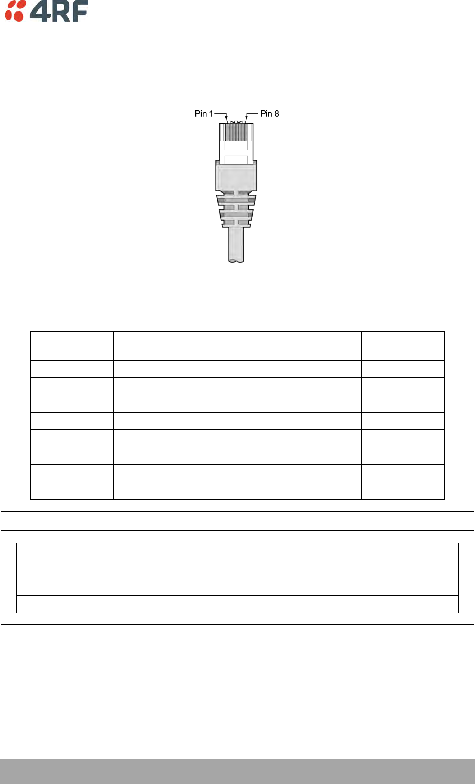
Interface Connections | 365
Aprisa SR+ User Manual 1.6.0 PO
11. Interface Connections
RJ45 Connector Pin Assignments
RJ45 pin numbering
Ethernet Interface Connections
Pin Number
Pin Function
Direction
TIA-568A Wire
Colour
TIA-568B Wire
Colour
1
Transmit
Output
Green/white
Orange/white
2
Transmit
Output
Green
Orange
3
Receive
Input
Orange/white
Green/white
4
Not used
Blue
Blue
5
Not used
Blue/white
Blue/white
6
Receive
Input
Orange
Green
7
Not used
Brown/white
Brown/white
8
Not used
Brown
Brown
Note: The TIA-568B wiring is the most commonly used and matches the cables we supply.
RJ45 connector LED indicators
LED
Status
Explanation
Green
On
Ethernet signal received
Orange
Flashing
Data traffic present on the interface
Note: Do not connect Power over Ethernet (PoE) connections to the Aprisa SR+ Ethernet ports as this will
damage the port.
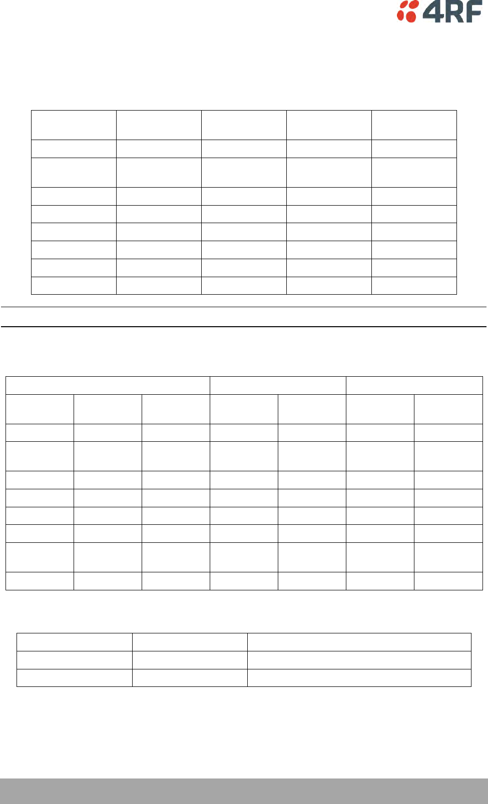
366 | Interface Connections
Aprisa SR+ User Manual 1.6.0 PO
RS-232 Serial Interface Connections
RS-232 Pinout
The Aprisa RS-232 Serial Interface is always configured as a DCE:
RJ45
Pin Number
Pin Function
Direction
TIA-568A Wire
Colour
TIA-568B Wire
Colour
1
RTS
Input
Green / white
Orange/white
2
DTR / Sleep
Mode
Input
Green
Orange
3
TXD
Input
Orange / white
Green/white
4
Ground
Blue
Blue
5
DCD
Output
Blue / white
Blue/white
6
RXD
Output
Orange
Green
7
DSR
Output
Brown / white
Brown/white
8
CTS
Output
Brown
Brown
Note: The TIA-568B wiring is the most commonly used and matches the cables we supply.
RS-232 Customer Cable Wiring
Aprisa RS-232 Interface - DCE
DTE Customer Interface
DCE Customer Interface
RJ45
Pin Number
Pin
Function
Direction
Pin
Function
DB9 Male
Pinout
Pin
Function
DB9 Female
Pinout
1
RTS
Input
RTS
7
CTS
8
2
DTR
Input
DTR / Sleep
Mode
4
DSR
6
3
TXD
Input
TXD
3
RXD
2
4
Ground
Ground
5
Ground
5
5
DCD
Output
DCD
1
6
RXD
Output
RXD
2
TXD
3
7
DSR
Output
DSR
6
DTR / Sleep
Mode
4
8
CTS
Output
CTS
8
RTS
7
RS-232 RJ45 LED Indicators
LED
Status
Explanation
Green
On
RS-232 device connected
Orange
Flashing
Data present on the interface
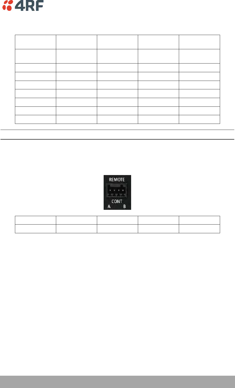
Interface Connections | 367
Aprisa SR+ User Manual 1.6.0 PO
Alarm Interface Connections
RJ45
Pin Number
Pin Function
Direction
TIA-568A Wire
Colour
TIA-568B Wire
Colour
1
Alarm 1 Input /
sleep control
Input
Green / white
Orange/white
2
Ground
Green
Orange
3
Alarm 2 Input
Input
Orange / white
Green/white
4
Ground
Blue
Blue
5
Alarm 1 Output
Output
Blue / white
Blue/white
6
Ground
Orange
Green
7
Alarm 2 Output
Output
Brown / white
Brown/white
8
Ground
Brown
Brown
Note: The TIA-568B wiring is the most commonly used and matches the cables we supply.
Protection Switch Remote Control Connections
1 2 3 4
Pin Number
1
2
3
4
Function
A radio active
Ground
B radio active
Ground

368 | Alarm Types and Sources
Aprisa SR+ User Manual 1.6.0 PO
12. Alarm Types and Sources
Alarm Types
There are three types of alarm event configuration types:
1. Threshold Type
These alarm events have lower and upper limits. An alarm is raised if current reading is outside the limits.
Note: the limits for PA Current, TX AGC, TX Reverse Power and Thermal shutdown are not user
configurable.
2. Error Ratio Type
This is the ratio of bad packets vs total packets in the defined sample duration.
For Serial, it is the ratio of bad characters vs total characters in the duration seconds. An alarm is raised if
current error ratio is greater than the configured ratio. The error ratio is configured in ‘Upper Limit’ field
and accepts value between 0 and 1. Monitoring of these events can be disabled by setting the duration
parameter to 0.
3. Sample Duration Type
Used for No Receive data events type. An alarm is raised if no data is received in the defined sample
duration. Monitoring of these events can be disabled by setting the duration parameter to 0.
See ‘Events > Events Setup’ on page 224 for setup of alarm thresholds / sample durations etc.

Alarm Types and Sources | 369
Aprisa SR+ User Manual 1.6.0 PO
Alarm Events
Transmitter Alarm Events
Event
ID
Event Display
Text
Default
Severity
Configuration
Type
Function
Recommended Actions
1
PA Current
critical(1)
Threshold Type
Alarm to indicate that the
current drawn by the
transmitter power amplifier
is outside defined limits.
Check antenna is not open or
shorted, check duplexer
correctly connected and
tuned, if OK replace radio.
61
PA Driver Current
critical(1)
Threshold Type
Alarm to indicate that the
current drawn by the
transmitter power amplifier
driver is outside defined
limits.
Check antenna is not open or
shorted, check duplexer
correctly connected and
tuned, if OK replace radio.
62
PA Stability
warning(4)
Threshold Type
Alarm to indicate that the
power amplifier is oscillating
which may cause corruption
of the TX signal
Check antenna is not open or
shorted, check duplexer
correctly connected and
tuned, if OK replace radio.
2
TX AGC
critical(1)
Threshold Type
Alarm to indicate that the
variable gain control of the
transmitter is outside
defined limits.
Check antenna is not open or
shorted, check duplexer
correctly connected and
tuned, if OK replace radio.
3
TX Reverse Power
warning(4)
Threshold Type
Alarm to indicate that the
antenna is not connected to
the radio
Check antenna is not open or
shorted, check duplexer
correctly connected and
tuned, and confirm VSWR at
TX port is less than 2:1. If
OK replace radio.
60
TX Forward
Power
warning(4)
Threshold Type
Alarm to indicate that the
transmitter power is outside
the selected TX power
setting.
Check antenna is not open or
shorted, check duplexer
correctly connected and
tuned, and confirm VSWR at
TX port is less than 2:1. If
OK replace radio.
4
Temperature
Threshold
warning(4)
Threshold Type
Alarm to indicate that the
transmitter temperature is
outside defined limits.
Check ambient temperature
and for airflow obstructions.
5
TX Synthesizer
Not Locked
critical(1)
Threshold Type
Alarm to indicate that the
transmitter synthesizer is not
locked.
Power off radio and restart.
If condition persists replace
radio.
31
Thermal
Shutdown
critical(1)
Threshold Type
Alarm to indicate that the
transmitter has shutdown
due to excessively high
temperature.
Check ambient temperature
and for airflow obstructions.
Receiver Alarm Events
Event
ID
Event Display
Text
Default
Severity
Configuration
Type
Function
Recommended Actions
7
RSSI Threshold
warning(4)
Threshold Type
Alarm to indicate that the
receiver RSSI reading taken
on the last packet received is
outside defined limits.
Check antenna is not open or
shorted. If the antenna is
directional check for off-
pointing.
8
RX Synthesizer
Not Locked
critical(1)
Not Configurable
Alarm to indicate that the
receiver Synthesizer is not
locked on the RF received
signal.
Power off radio and restart.
If condition persists replace
radio.
9
RX CRC Errors
warning(4)
Error Ratio Type
Alarm to indicate that the
data received on the RF path
contains errors at a higher
rate than the defined error
rate threshold.
Check antenna is not open or
shorted. Check duplexer is
correctly tuned. If the
antenna is directional check
for off-pointing. Power off
radio and restart. If
condition persists replace
radio.
370 | Alarm Types and Sources
Aprisa SR+ User Manual 1.6.0 PO
Radio Interface Path Alarm Events
Event
ID
Event Display
Text
Default
Severity
Configuration
Type
Function
Recommended Actions
34
RF No Receive
Data
warning(4)
Sample Duration
Type
Alarm to indicate that there
is no data received on the RF
path in the defined duration
period.
Check master is operational.
If new deployment check set-
up, frequencies, and
duplexer (if used). Check
antenna is not open or
shorted. If the antenna is
directional check for off-
pointing. Power off radio
and restart. If condition
persists replace radio.
Modem Alarm Events
Event
ID
Event Display
Text
Default
Severity
Configuration
Type
Function
Recommended Actions
68
Modem FEC
disable
warning(4)
Not Configurable
Alarm to indicate that FEC
has been disabled. This could
be a permanent event or a
timed event.
Alarm to indicate that FEC
has been disabled. This could
be a permanent event or a
timed event.
70
Modem ACM
locked
warning(4)
Not Configurable
Alarm to indicate that the
ACM has been locked to a
fixed coding and modulation.
This could be a permanent
event or a timed event.
Alarm to indicate that the
ACM has been locked to a
fixed coding and modulation.
This could be a permanent
event or a timed event.
Customer Equipment Interface Path Alarm Events
Event
ID
Event Display
Text
Default
Severity
Configuration
Type
Function
Recommended Actions
10
Port 1 Eth No
Receive Data
warning(4)
Sample Duration
Type
Alarm to indicate that
Ethernet port 1 has no
received input signal in the
defined duration period.
Check Ethernet cable and
connector. Check switch
port or RTU is active. Check
IP and VLAN configuration.
11
Port 1 Eth Data
Receive Errors
warning(4)
Error Ratio Type
Alarm to indicate that
Ethernet port 1 received
input signal contains errors
at a higher rate than the
defined error rate threshold.
Check Ethernet cable and
connector. Check switch
port or RTU is active. Check
IP and VLAN configuration.
12
Port 1 Eth Data
Transmit Errors
warning(4)
Error Ratio Type
Alarm to indicate that
Ethernet port 1 transmitted
output signal contains errors
at a higher rate than the
defined error rate threshold.
Check Ethernet cable and
connector. Check switch
port or RTU is active. Check
IP and VLAN configuration.
35
Port 2 Eth No
Receive Data
warning(4)
Sample Duration
Type
Alarm to indicate that
Ethernet port 2 has no
received input signal in the
defined duration period.
Check Ethernet cable and
connector. Check switch
port or RTU is active. Check
IP and VLAN configuration.
36
Port 2 Eth Data
Receive Errors
warning(4)
Error Ratio Type
Alarm to indicate that
Ethernet port 2 received
input signal contains errors
at a higher rate than the
defined error rate threshold.
Check Ethernet cable and
connector. Check switch
port or RTU is active. Check
IP and VLAN configuration.
37
Port 2 Eth Data
Transmit Errors
warning(4)
Error Ratio Type
Alarm to indicate that
Ethernet port 2 transmitted
output signal contains errors
at a higher rate than the
defined error rate threshold.
Check Ethernet cable and
connector. Check switch
port or RTU is active. Check
IP and VLAN configuration.
44
Port 3 Eth No
Receive Data
warning(4)
Sample Duration
Type
Alarm to indicate that
Ethernet port 3 has no
received input signal in the
defined duration period.
Check Ethernet cable and
connector. Check switch
port or RTU is active. Check
IP and VLAN configuration.
Alarm Types and Sources | 371
Aprisa SR+ User Manual 1.6.0 PO
Event
ID
Event Display
Text
Default
Severity
Configuration
Type
Function
Recommended Actions
45
Port 3 Eth Data
Receive Errors
warning(4)
Error Ratio Type
Alarm to indicate that
Ethernet port 3 received
input signal contains errors
at a higher rate than the
defined error rate threshold.
Check Ethernet cable and
connector. Check switch
port or RTU is active. Check
IP and VLAN configuration.
46
Port 3 Eth Data
Transmit Errors
warning(4)
Error Ratio Type
Alarm to indicate that
Ethernet port 3 transmitted
output signal contains errors
at a higher rate than the
defined error rate threshold.
Check Ethernet cable and
connector. Check switch
port or RTU is active. Check
IP and VLAN configuration.
48
Port 4 Eth No
Receive Data
warning(4)
Sample Duration
Type
Alarm to indicate that
Ethernet port 4 has no
received input signal in the
defined duration period.
Check Ethernet cable and
connector. Check switch
port or RTU is active. Check
IP and VLAN configuration.
49
Port 4 Eth Data
Receive Errors
warning(4)
Error Ratio Type
Alarm to indicate that
Ethernet port 4 received
input signal contains errors
at a higher rate than the
defined error rate threshold.
Check Ethernet cable and
connector. Check switch
port or RTU is active. Check
IP and VLAN configuration.
50
Port 4 Eth Data
Transmit Errors
warning(4)
Error Ratio Type
Alarm to indicate that
Ethernet port 4 transmitted
output signal contains errors
at a higher rate than the
defined error rate threshold.
Check Ethernet cable and
connector. Check switch
port or RTU is active. Check
IP and VLAN configuration.
13
Port 1 Serial Data
No Receive Data
warning(4)
Sample Duration
Type
Alarm to indicate that the
RS-232 port 1 has no received
input signal in the defined
duration period.
Check serial ports settings,
check serial cable and
connector.
14
Port 1 Serial Data
Receive Errors
warning(4)
Error Ratio Type
Alarm to indicate that the
RS-232 port 1 received input
signal contains errors at a
higher rate than the defined
error rate threshold.
Check serial ports settings,
check serial cable and
connector.
52
Port 2 Serial Data
No Receive Data
warning(4)
Sample Duration
Type
Alarm to indicate that the
RS-232 port 2 has no received
input signal in the defined
duration period.
Check serial ports settings,
check serial cable and
connector.
53
Port 2 Serial Data
Receive Errors
warning(4)
Error Ratio Type
Alarm to indicate that the
RS-232 port 2 received input
signal contains errors at a
higher rate than the defined
error rate threshold.
Check serial ports settings,
check serial cable and
connector.
63
USB Port Serial
Data No Receive
Data
warning(4)
Sample Duration
Type
Alarm to indicate that the
USB port has no received
input signal in the defined
duration period.
Check serial ports settings,
check USB serial cable and
adapter, check serial
connector.
64
USB Port Serial
Data Receive
Errors
warning(4)
Error Ratio Type
Alarm to indicate that the
USB port received input
signal contains errors at a
higher rate than the defined
error rate threshold.
Check serial ports settings,
check USB serial cable and
adapter, check serial
connector.
Component Failure Alarm Events
Event
ID
Event Display
Text
Default
Severity
Configuration
Type
Function
Recommended Actions
16
Component
Failure
major(2)
Not Configurable
Alarm to indicate that a
hardware component has
failed.
Power off and restart radio.
If fault persists replace
radio.
372 | Alarm Types and Sources
Aprisa SR+ User Manual 1.6.0 PO
Hardware Alarm Events
Event
ID
Event Display
Text
Default
Severity
Configuration
Type
Function
Recommended Actions
56
VDC Power
Supply
warning(4)
Not Configurable
Alarm to indicate that the
input power source is outside
the operating limits of 10 to
30 VDC
Check DC connection to
radio. Replace power supply.
57
3.3 Volts Power
Supply
warning(4)
Not Configurable
Alarm to indicate that the
3.3 volt power rail is outside
defined limits.
Power off and restart radio.
If fault persists replace
radio.
58
5.0 Volts Power
Supply
warning(4)
Not Configurable
Alarm to indicate that the
5.0 volt power rail is outside
defined limits.
Power off and restart radio.
If fault persists replace
radio.
59
7.2 Volts Power
Supply
warning(4)
Not Configurable
Alarm to indicate that the
7.2 volt power rail is outside
defined limits.
Power off and restart radio.
If fault persists replace
radio.
71
15 Volts Power
Supply
warning(4)
Not Configurable
Alarm to indicate that the 15
volt power rail is outside
defined limits.
Power off and restart radio.
If fault persists replace
radio.
Software Alarm Events
Event
ID
Event Display
Text
Default
Severity
Configuration
Type
Function
Recommended Actions
20
Calibration
Failure
major(2)
Not Configurable
Alarm to indicate that the RF
calibration has failed.
Power off and restart radio.
If fault persists replace
radio.
21
Configuration Not
Supported
major(2)
Not Configurable
Alarm to indicate that a
configuration has entered
that is invalid.
Restore previous
configuration, remove out of
range or invalid parameters,
updated software.
32
Network
Configuration
Warning
warning(4)
Not Configurable
Alarm to indicate a network
configuration problem e.g.
remote not registered.
Check for invalid parameters.
Audit network settings.
73
Radio Network
warning(4)
Not Configurable
Alarm to indicate that there
is an alarm in the radio
network e.g. a remote radio
has not registered or
duplicate IP address.
Check for duplicate or invalid
parameters. Audit network
settings.
39
Software Restart
Required
warning(4)
Not Configurable
Alarm to indicate that a
configuration has changed
that requires a software
reboot.
Reboot radio.
Hardware Alarm Input Alarm Events
Event
ID
Event Display
Text
Default
Severity
Configuration
Type
Function
Recommended Actions
24
Alarm Input 1
warning(4)
Not Configurable
Alarm to indicate that there
is an active alarm on
hardware alarm input 1
Action depends on nature of
third-party alarm.
25
Alarm Input 2
warning(4)
Not Configurable
Alarm to indicate that there
is an active alarm on
hardware alarm input 2
Action depends on nature of
third-party alarm.

Alarm Types and Sources | 373
Aprisa SR+ User Manual 1.6.0 PO
Protected Station Alarm Events
Event
ID
Event Display
Text
Default
Severity
Configuration
Type
Function
Recommended Actions
17
Protection Sw
Manual Lock
warning(4)
Not Configurable
Alarm to indicate that the
Protection Switch Software
Manual Lock has been
activated.
Information only.
18
Protection Hw
Manual Lock
warning(4)
Not Configurable
Alarm to indicate that the
Protection Switch Hardware
Manual Lock has been
activated.
Remember to unlock the
Hardware Manual Lock for
normal operation
23
Protection Peer
Comms Lost
major(2)
Not Configurable
Alarm to indicate that the
standby radio has lost
communication with the
active radio.
Check that the partner radio
is powered on and the
‘Protect’ cable is plugged
from the switch to both
radios.
Check that the radios have
been setup for protected
operation.
54
Protection
Hardware Failure
major(2)
Not Configurable
Alarm to indicate that there
is a failure in the protection
switch hardware.
Check that the cables are
connecting the switch to
both radios.
Check that the switch and
both radios are the same
Data interface port options
e.g. 2E2S
374 | Alarm Types and Sources
Aprisa SR+ User Manual 1.6.0 PO
Informational Events
Event
ID
Event Display
Text
Default
Severity
Function
Recommended Actions
26
User
authentication
succeeded
information
(5)
Event to indicate that a user is
successfully authenticated on the radio
during login. The information on the
user that was successfully
authenticated is provided in the
eventHistoryInfo object of the Event
History Log.
Information
No action required unless unexpected
27
User
authentication
failed
information
(5)
Event to indicate that a user has failed
to be authenticated on the radio during
login. The information on the user that
was unsuccessfully authenticated is
provided in the eventHistoryInfo object
of the Event History Log.
Check for possible intrusion attempt.
If unexpected follow cyber incident
report procedure.
28
Protection switch
failed
information
(5)
Event to indicate that a protection
switch-over cannot occur for some
reason. The reason for the failure to
switch is described in the
eventHistoryInfo object of the Event
History Log.
Investigate reason for switch over and
take remedial action.
29
Software System
Check
information
(5)
Event to indicate that the software has
done a system check on the radio. Any
information relevant to the cause of the
event is provided in the
eventHistoryInfo object of the Event
History Log.
Information
No action required unless unexpected
30
Software Start Up
information
(5)
Event to indicate that the radio
software has started. Any information
relevant to the software start up is
provided in the eventHistoryInfo object
of the Event History Log.
Information
No action required unless unexpected
33
Protection Switch
Occurred
information
(5)
Event to indicate that a protection
switch-over occurs for some reason.
The reason for the switch-over is
described in the eventHistoryInfo
object of the Event History Log.
Investigate reason for switch over and
take remedial action.
41
File Transfer
Activity
information
(5)
Event to indicate that a data file is
being transferred to or from the radio.
Information
No action required unless unexpected
42
Software
Management
Activity
information
(5)
Event to indicate that software is being
distributed to remote radios.
Information
No action required unless unexpected
43
Terminal Server
TCP Activity
information
(5)
Event to indicate TCP packets are being
transferred from the terminal server.
Information
No action required unless unexpected
55
Terminal Unit
Information
information
(5)
Event to indicate a miscellaneous
activity occurring on the radio
Information no action required unless
unexpected.
65
Event Action
Activity
information
(5)
Event to indicate an event action
occurring on the radio
Information
No action required unless unexpected
72
User SuperVisor
Session Logout
information
(5)
Event to indicate that a user has logged
out or the user session has timed out
Information
No action required unless unexpected
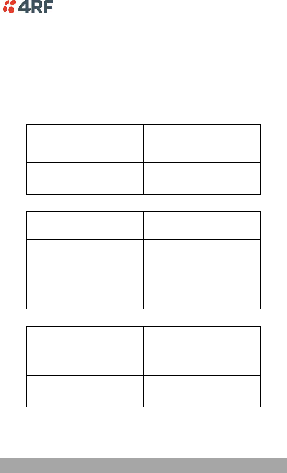
Specifications | 375
Aprisa SR+ User Manual 1.6.0 PO
13. Specifications
RF Specifications
Blocking (desensitization), intermodulation, spurious response rejection, and adjacent channel selectivity
values determined according to the methods introduced in V1.7.1 of ETSI standards EN 300 113-1.
Frequency Bands
ETSI Compliant
Broadcast Band
Frequency Band
Frequency Tuning
Range
Synthesizer Step
Size
VHF
135 MHz
135-175 MHz
0.625 kHz
UHF
220 MHz
215-240 MHz
0.625 kHz
UHF
320 MHz
320-400 MHz
6.250 kHz
UHF
400 MHz
400-470 MHz
6.250 kHz
UHF
450 MHz
450-520 MHz
6.250 kHz
FCC Compliant
Broadcast Band
Frequency Band
Frequency Tuning
Range
Synthesizer Step
Size
VHF
135 MHz
135-175 MHz
0.625 kHz
UHF
220 MHz
215-240 MHz
0.625 kHz
UHF
400 MHz
400-470 MHz
6.250 kHz
UHF
450 MHz
450-520 MHz
6.250 kHz
UHF
700 MHz
757-758 MHz and
787-788 MHz
6.250 kHz
UHF
896 MHz
896-902 MHz (Note 1)
6.250 kHz
UHF
928 MHz
928-960 MHz (Note 1)
6.250 kHz
IC Compliant
Broadcast Band
Frequency Band
Frequency Tuning
Range
Synthesizer Step
Size
VHF
135 MHz
135-175 MHz
0.625 kHz
UHF
220 MHz
215-240 MHz
0.625 kHz
UHF
220 MHz
215-240 MHz
3.125 kHz
UHF
400 MHz
400-470 MHz
6.250 kHz
UHF
896 MHz
896-902 MHz (Note 1)
6.250 kHz
UHF
928 MHz
928-960 MHz (Note 1)
6.250 kHz
The Frequency Tuning Range is not an indication of the exact frequencies approved by FCC / IC.
Note 1: The receive tuning range is specified. The transmit tuning range is 896 - 960 MHz.
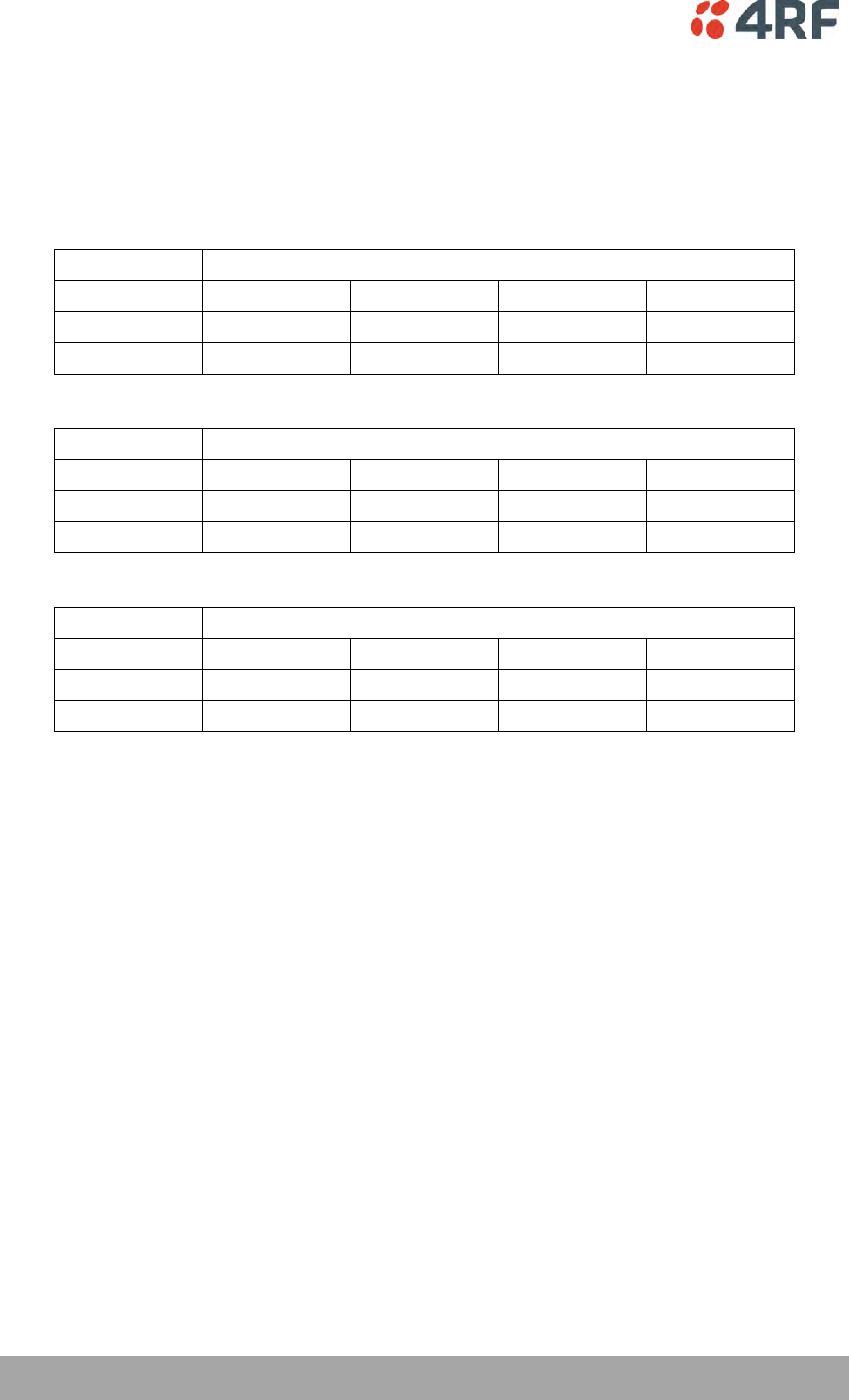
376 | Specifications
Aprisa SR+ User Manual 1.6.0 PO
Channel Sizes
ETSI Compliant
ETSI: 135 MHz Band
No Forward Error Correction
Channel Size
Gross Radio Capacity
64 QAM
16 QAM
QPSK
4-CPFSK
12.5 kHz
60.0 kbit/s
40.0 kbit/s
20.0 kbit/s
9.6 kbit/s
25 kHz
120.0 kbit/s
80.0 kbit/s
40.0 kbit/s
19.2 kbit/s
Minimum Coded Forward Error Correction
Channel Size
Gross Radio Capacity less FEC
64 QAM
16 QAM
QPSK
4-CPFSK
12.5 kHz
52.0 kbit/s
23.1 kbit/s
11.6 kbit/s
8.4 kbit/s
25 kHz
103.9 kbit/s
46.2 kbit/s
23.1 kbit/s
16.7 kbit/s
Maximum Coded Forward Error Correction
Channel Size
Gross Radio Capacity less FEC
64 QAM
16 QAM
QPSK
4-CPFSK
12.5 kHz
45.6 kbit/s
17.3 kbit/s
8.7 kbit/s
4.1 kbit/s
25 kHz
91.2 kbit/s
34.6 kbit/s
17.3 kbit/s
8.3 kbit/s

Specifications | 377
Aprisa SR+ User Manual 1.6.0 PO
ETSI: 220 / 320 / 400 MHz Bands
No Forward Error Correction
Channel Size
Gross Radio Capacity
64 QAM
16 QAM
QPSK
4-CPFSK
12.5 kHz
60.0 kbit/s
40.0 kbit/s
20.0 kbit/s
9.6 kbit/s
20 kHz
84.0 kbit/s
56.0 kbit/s
28.0 kbit/s
9.6 kbit/s
25 kHz
120.0 kbit/s
80.0 kbit/s
40.0 kbit/s
19.2 kbit/s
50 kHz (1)
216.0 kbit/s
144.0 kbit/s
72.0 kbit/s
38.4 kbit/s
Minimum Coded Forward Error Correction
Channel Size
Gross Radio Capacity less FEC
64 QAM
16 QAM
QPSK
4-CPFSK
12.5 kHz
52.0 kbit/s
23.1 kbit/s
11.6 kbit/s
8.4 kbit/s
20 kHz
72.7 kbit/s
32.4 kbit/s
16.2 kbit/s
8.4 kbit/s
25 kHz
103.9 kbit/s
46.2 kbit/s
23.1 kbit/s
16.7 kbit/s
50 kHz (1)
187.1 kbit/s
83.2 kbit/s
41.6 kbit/s
33.4 kbit/s
Maximum Coded Forward Error Correction
Channel Size
Gross Radio Capacity less FEC
64 QAM
16 QAM
QPSK
4-CPFSK
12.5 kHz
45.6 kbit/s
17.3 kbit/s
8.7 kbit/s
4.1 kbit/s
20 kHz
63.8 kbit/s
24.2 kbit/s
12.1 kbit/s
4.1 kbit/s
25 kHz
91.2 kbit/s
34.6 kbit/s
17.3 kbit/s
8.3 kbit/s
50 kHz (1)
164.2 kbit/s
62.4 kbit/s
31.2 kbit/s
16.5 kbit/s
Note 1: It is the responsibility of the user to check for country regulatory of 50 kHz availability in this
frequency band.

378 | Specifications
Aprisa SR+ User Manual 1.6.0 PO
ETSI: 450 MHz Band
No Forward Error Correction
Channel Size
Gross Radio Capacity
64 QAM
16 QAM
QPSK
4-CPFSK
12.5 kHz
60.0 kbit/s
40.0 kbit/s
20.0 kbit/s
9.6 kbit/s
25 kHz
120.0 kbit/s
80.0 kbit/s
40.0 kbit/s
19.2 kbit/s
50 kHz (1)
216.0 kbit/s
144.0 kbit/s
72.0 kbit/s
38.4 kbit/s
Minimum Coded Forward Error Correction
Channel Size
Gross Radio Capacity less FEC
64 QAM
16 QAM
QPSK
4-CPFSK
12.5 kHz
52.0 kbit/s
23.1 kbit/s
11.6 kbit/s
8.4 kbit/s
25 kHz
103.9 kbit/s
46.2 kbit/s
23.1 kbit/s
16.7 kbit/s
50 kHz (1)
187.1 kbit/s
83.2 kbit/s
41.6 kbit/s
33.4 kbit/s
Maximum Coded Forward Error Correction
Channel Size
Gross Radio Capacity less FEC
64 QAM
16 QAM
QPSK
4-CPFSK
12.5 kHz
45.6 kbit/s
17.3 kbit/s
8.7 kbit/s
4.1 kbit/s
25 kHz
91.2 kbit/s
34.6 kbit/s
17.3 kbit/s
8.3 kbit/s
50 kHz (1)
164.2 kbit/s
62.4 kbit/s
31.2 kbit/s
16.5 kbit/s
Note 1: It is the responsibility of the user to check for country regulatory of 50 kHz availability in this
frequency band.

Specifications | 379
Aprisa SR+ User Manual 1.6.0 PO
FCC Compliant
FCC: 135 MHz Band
No Forward Error Correction
Channel Size
Gross Radio Capacity
64 QAM
16 QAM
QPSK
4-CPFSK
15 kHz
54.0 kbit/s
36.0 kbit/s
18.0 kbit/s
9.6 kbit/s
30 kHz
96.0 kbit/s
64.0 kbit/s
32.0 kbit/s
19.2 kbit/s
Minimum Coded Forward Error Correction
Channel Size
Gross Radio Capacity less FEC
64 QAM
16 QAM
QPSK
4-CPFSK
15 kHz
46.8 kbit/s
20.8 kbit/s
10.4 kbit/s
8.4 kbit/s
30 kHz
83.1 kbit/s
37.0 kbit/s
18.5 kbit/s
16.7 kbit/s
Maximum Coded Forward Error Correction
Channel Size
Gross Radio Capacity less FEC
64 QAM
16 QAM
QPSK
4-CPFSK
15 kHz
41.0 kbit/s
15.6 kbit/s
7.8 kbit/s
4.1 kbit/s
30 kHz
73.0 kbit/s
27.7 kbit/s
13.9 kbit/s
8.3 kbit/s
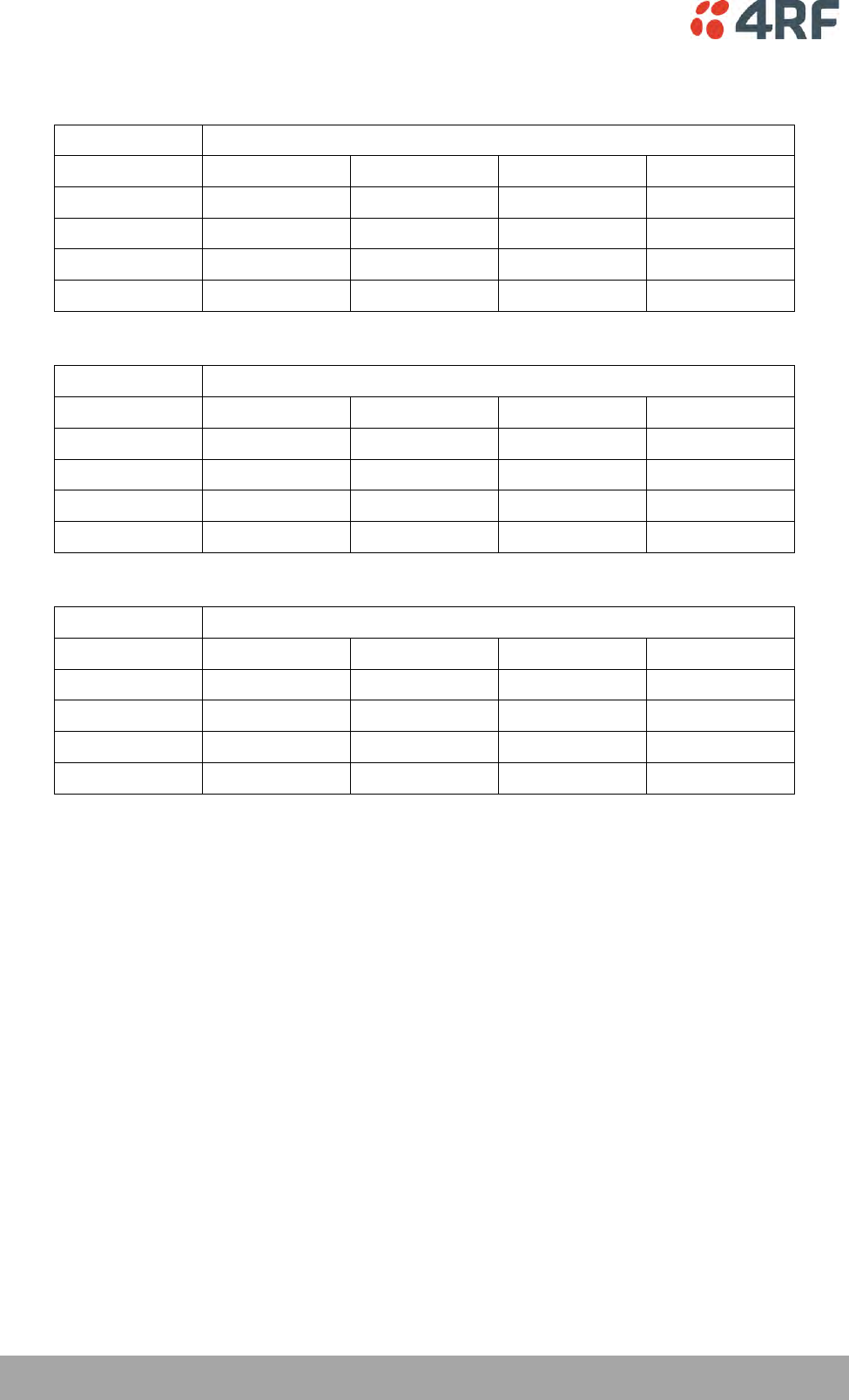
380 | Specifications
Aprisa SR+ User Manual 1.6.0 PO
FCC: 220 MHz Band
No Forward Error Correction
Channel Size
Gross Radio Capacity
64 QAM
16 QAM
QPSK
4-CPFSK
12.5 kHz
54.0 kbit/s
36.0 kbit/s
18.0 kbit/s
9.6 kbit/s
15 kHz
60.0 kbit/s
40.0 kbit/s
20.0 kbit/s
9.6 kbit/s
25 kHz
96.0 kbit/s
64.0 kbit/s
32.0 kbit/s
19.2 kbit/s
50 kHz
216.0 kbit/s
144.0 kbit/s
72.0 kbit/s
38.4 kbit/s
Minimum Coded Forward Error Correction
Channel Size
Gross Radio Capacity less FEC
64 QAM
16 QAM
QPSK
4-CPFSK
12.5 kHz
46.8 kbit/s
20.8 kbit/s
10.4 kbit/s
8.4 kbit/s
15 kHz
52.0 kbit/s
23.1 kbit/s
11.6 kbit/s
8.4 kbit/s
25 kHz
83.1 kbit/s
37.0 kbit/s
18.5 kbit/s
16.7 kbit/s
50 kHz
187.1 kbit/s
83.2 kbit/s
41.6 kbit/s
33.4 kbit/s
Maximum Coded Forward Error Correction
Channel Size
Gross Radio Capacity less FEC
64 QAM
16 QAM
QPSK
4-CPFSK
12.5 kHz
41.0 kbit/s
15.6 kbit/s
7.8 kbit/s
4.1 kbit/s
15 kHz
45.6 kbit/s
17.3 kbit/s
8.7 kbit/s
4.1 kbit/s
25 kHz
73.0 kbit/s
27.7 kbit/s
13.9 kbit/s
8.3 kbit/s
50 kHz
164.2 kbit/s
62.4 kbit/s
31.2 kbit/s
16.5 kbit/s

Specifications | 381
Aprisa SR+ User Manual 1.6.0 PO
FCC: 400 MHz Band
No Forward Error Correction
Channel Size
Gross Radio Capacity
64 QAM
16 QAM
QPSK
4-CPFSK
12.5 kHz
54.0 kbit/s
36.0 kbit/s
18.0 kbit/s
9.6 kbit/s
25 kHz
96.0 kbit/s
64.0 kbit/s
32.0 kbit/s
19.2 kbit/s
50 kHz (1)
216.0 kbit/s
144.0 kbit/s
72.0 kbit/s
38.4 kbit/s
Minimum Coded Forward Error Correction
Channel Size
Gross Radio Capacity less FEC
64 QAM
16 QAM
QPSK
4-CPFSK
12.5 kHz
46.8 kbit/s
20.8 kbit/s
10.4 kbit/s
8.4 kbit/s
25 kHz
83.1 kbit/s
37.0 kbit/s
18.5 kbit/s
16.7 kbit/s
50 kHz (1)
187.1 kbit/s
83.2 kbit/s
41.6 kbit/s
33.4 kbit/s
Maximum Coded Forward Error Correction
Channel Size
Gross Radio Capacity less FEC
64 QAM
16 QAM
QPSK
4-CPFSK
12.5 kHz
41.0 kbit/s
15.6 kbit/s
7.8 kbit/s
4.1 kbit/s
25 kHz
73.0 kbit/s
27.7 kbit/s
13.9 kbit/s
8.3 kbit/s
50 kHz (1)
164.2 kbit/s
62.4 kbit/s
31.2 kbit/s
16.5 kbit/s
Note 1: It is the responsibility of the user to check for country regulatory of 50 kHz availability in this
frequency band.

382 | Specifications
Aprisa SR+ User Manual 1.6.0 PO
FCC: 450 MHz Band
No Forward Error Correction
Channel Size
Gross Radio Capacity
64 QAM
16 QAM
QPSK
4-CPFSK
12.5 kHz
54.0 kbit/s
36.0 kbit/s
18.0 kbit/s
9.6 kbit/s
25 kHz
96.0 kbit/s
64.0 kbit/s
32.0 kbit/s
19.2 kbit/s
Minimum Coded Forward Error Correction
Channel Size
Gross Radio Capacity less FEC
64 QAM
16 QAM
QPSK
4-CPFSK
12.5 kHz
46.8 kbit/s
20.8 kbit/s
10.4 kbit/s
8.4 kbit/s
25 kHz
83.1 kbit/s
37.0 kbit/s
18.5 kbit/s
16.7 kbit/s
Maximum Coded Forward Error Correction
Channel Size
Gross Radio Capacity less FEC
64 QAM
16 QAM
QPSK
4-CPFSK
12.5 kHz
41.0 kbit/s
15.6 kbit/s
7.8 kbit/s
4.1 kbit/s
25 kHz
73.0 kbit/s
27.7 kbit/s
13.9 kbit/s
8.3 kbit/s
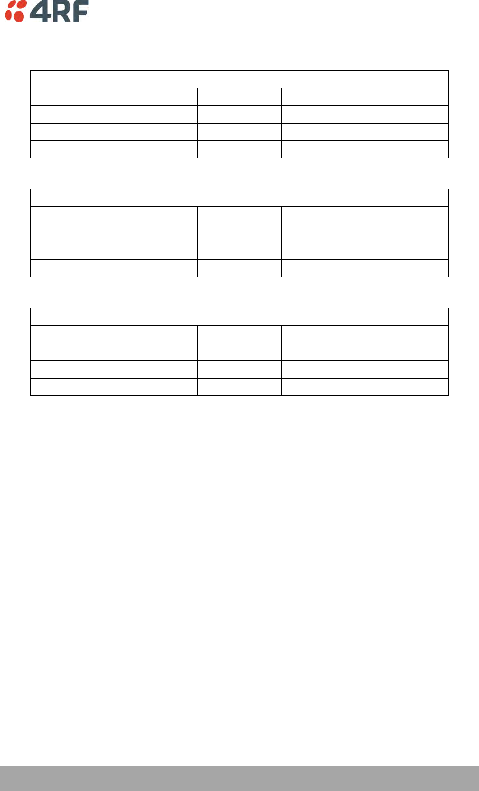
Specifications | 383
Aprisa SR+ User Manual 1.6.0 PO
FCC: 700 MHz Band
No Forward Error Correction
Channel Size
Gross Radio Capacity
64 QAM
16 QAM
QPSK
4-CPFSK (2)
25 kHz
120.0 kbit/s
80.0 kbit/s
40.0 kbit/s
19.2 kbit/s
50 kHz
240.0 kbit/s
160.0 kbit/s
80.0 kbit/s
38.4 kbit/s
75 kHz (1)
360.0 kbit/s
240.0 kbit/s
120.0 kbit/s
57.6 kbit/s
Minimum Coded Forward Error Correction
Channel Size
Gross Radio Capacity less FEC
64 QAM
16 QAM
QPSK
4-CPFSK (2)
25 kHz
103.9 kbit/s
46.2 kbit/s
23.1 kbit/s
16.7 kbit/s
50 kHz
207.8 kbit/s
92.5 kbit/s
46.2 kbit/s
33.4 kbit/s
75 kHz (1)
311.8 kbit/s
138.7 kbit/s
69.4 kbit/s
50.1 kbit/s
Maximum Coded Forward Error Correction
Channel Size
Gross Radio Capacity less FEC
64 QAM
16 QAM
QPSK
4-CPFSK (2)
25 kHz
91.2 kbit/s
34.6 kbit/s
17.3 kbit/s
8.3 kbit/s
50 kHz
182.4 kbit/s
69.3 kbit/s
34.6 kbit/s
16.5 kbit/s
75 kHz (1)
273.6 kbit/s
103.9 kbit/s
52.0 kbit/s
24.8 kbit/s
Note 1: Available in future software release.
Note 2: Please consult 4RF for availability.
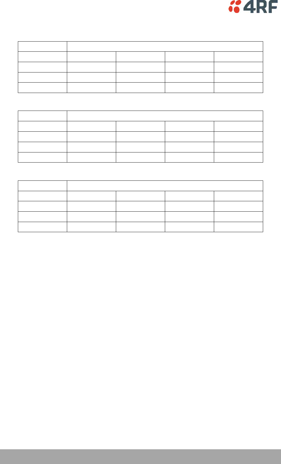
384 | Specifications
Aprisa SR+ User Manual 1.6.0 PO
FCC: 896 / 928 MHz Bands
No Forward Error Correction
Channel Size
Gross Radio Capacity
64 QAM
16 QAM
QPSK
4-CPFSK
12.5 kHz
60.0 kbit/s
40.0 kbit/s
20.0 kbit/s
9.6 kbit/s
25 kHz
96.0 kbit/s
64.0 kbit/s
32.0 kbit/s
19.2 kbit/s
50 kHz
216.0 kbit/s
144.0 kbit/s
72.0 kbit/s
38.4 kbit/s
Minimum Coded Forward Error Correction
Channel Size
Gross Radio Capacity less FEC
64 QAM
16 QAM
QPSK
4-CPFSK
12.5 kHz
52.0 kbit/s
23.1 kbit/s
11.6 kbit/s
8.4 kbit/s
25 kHz
83.1 kbit/s
37.0 kbit/s
18.5 kbit/s
16.7 kbit/s
50 kHz
187.1 kbit/s
83.2 kbit/s
41.6 kbit/s
33.4 kbit/s
Maximum Coded Forward Error Correction
Channel Size
Gross Radio Capacity less FEC
64 QAM
16 QAM
QPSK
4-CPFSK
12.5 kHz
45.6 kbit/s
17.3 kbit/s
8.7 kbit/s
4.1 kbit/s
25 kHz
73.0 kbit/s
27.7 kbit/s
13.9 kbit/s
8.3 kbit/s
50 kHz
164.2 kbit/s
62.4 kbit/s
31.2 kbit/s
16.5 kbit/s

Specifications | 385
Aprisa SR+ User Manual 1.6.0 PO
IC Compliant
IC: 135 MHz Band
No Forward Error Correction
Channel Size
Gross Radio Capacity
64 QAM
16 QAM
QPSK
4-CPFSK
15 kHz
54.0 kbit/s
36.0 kbit/s
18.0 kbit/s
9.6 kbit/s
30 kHz
96.0 kbit/s
64.0 kbit/s
32.0 kbit/s
19.2 kbit/s
Minimum Coded Forward Error Correction
Channel Size
Gross Radio Capacity less FEC
64 QAM
16 QAM
QPSK
4-CPFSK
15 kHz
46.8 kbit/s
20.8 kbit/s
10.4 kbit/s
8.4 kbit/s
30 kHz
83.1 kbit/s
37.0 kbit/s
18.5 kbit/s
16.7 kbit/s
Maximum Coded Forward Error Correction
Channel Size
Gross Radio Capacity less FEC
64 QAM
16 QAM
QPSK
4-CPFSK
15 kHz
41.0 kbit/s
15.6 kbit/s
7.8 kbit/s
4.1 kbit/s
30 kHz
73.0 kbit/s
27.7 kbit/s
13.9 kbit/s
8.3 kbit/s

386 | Specifications
Aprisa SR+ User Manual 1.6.0 PO
IC: 220 MHz Band
No Forward Error Correction
Channel Size
Gross Radio Capacity
64 QAM
16 QAM
QPSK
4-CPFSK
12.5 kHz
54.0 kbit/s
36.0 kbit/s
18.0 kbit/s
9.6 kbit/s
15 kHz
60.0 kbit/s
40.0 kbit/s
20.0 kbit/s
9.6 kbit/s
25 kHz
96.0 kbit/s
64.0 kbit/s
32.0 kbit/s
19.2 kbit/s
50 kHz
216.0 kbit/s
144.0 kbit/s
72.0 kbit/s
38.4 kbit/s
Minimum Coded Forward Error Correction
Channel Size
Gross Radio Capacity less FEC
64 QAM
16 QAM
QPSK
4-CPFSK
12.5 kHz
46.8 kbit/s
20.8 kbit/s
10.4 kbit/s
8.4 kbit/s
15 kHz
52.0 kbit/s
23.1 kbit/s
11.6 kbit/s
8.4 kbit/s
25 kHz
83.1 kbit/s
37.0 kbit/s
18.5 kbit/s
16.7 kbit/s
50 kHz
187.1 kbit/s
83.2 kbit/s
41.6 kbit/s
33.4 kbit/s
Maximum Coded Forward Error Correction
Channel Size
Gross Radio Capacity less FEC
64 QAM
16 QAM
QPSK
4-CPFSK
12.5 kHz
41.0 kbit/s
15.6 kbit/s
7.8 kbit/s
4.1 kbit/s
15 kHz
45.6 kbit/s
17.3 kbit/s
8.7 kbit/s
4.1 kbit/s
25 kHz
73.0 kbit/s
27.7 kbit/s
13.9 kbit/s
8.3 kbit/s
50 kHz
164.2 kbit/s
62.4 kbit/s
31.2 kbit/s
16.5 kbit/s

Specifications | 387
Aprisa SR+ User Manual 1.6.0 PO
IC: 400 MHz Band
No Forward Error Correction
Channel Size
Gross Radio Capacity
64 QAM
16 QAM
QPSK
4-CPFSK
12.5 kHz
54.0 kbit/s
36.0 kbit/s
18.0 kbit/s
9.6 kbit/s
25 kHz
96.0 kbit/s
64.0 kbit/s
32.0 kbit/s
19.2 kbit/s
50 kHz (1)
216.0 kbit/s
144.0 kbit/s
72.0 kbit/s
38.4 kbit/s
Minimum Coded Forward Error Correction
Channel Size
Gross Radio Capacity less FEC
64 QAM
16 QAM
QPSK
4-CPFSK
12.5 kHz
46.8 kbit/s
20.8 kbit/s
10.4 kbit/s
8.4 kbit/s
25 kHz
83.1 kbit/s
37.0 kbit/s
18.5 kbit/s
16.7 kbit/s
50 kHz (1)
187.1 kbit/s
83.2 kbit/s
41.6 kbit/s
33.4 kbit/s
Maximum Coded Forward Error Correction
Channel Size
Gross Radio Capacity less FEC
64 QAM
16 QAM
QPSK
4-CPFSK
12.5 kHz
41.0 kbit/s
15.6 kbit/s
7.8 kbit/s
4.1 kbit/s
25 kHz
73.0 kbit/s
27.7 kbit/s
13.9 kbit/s
8.3 kbit/s
50 kHz (1)
164.2 kbit/s
62.4 kbit/s
31.2 kbit/s
16.5 kbit/s
Note 1: It is the responsibility of the user to check for country regulatory of 50 kHz availability in this
frequency band.

388 | Specifications
Aprisa SR+ User Manual 1.6.0 PO
IC: 896 / 928 MHz Bands
No Forward Error Correction
Channel Size
Gross Radio Capacity
64 QAM
16 QAM
QPSK
4-CPFSK
12.5 kHz
60.0 kbit/s
40.0 kbit/s
20.0 kbit/s
9.6 kbit/s
25 kHz
96.0 kbit/s
64.0 kbit/s
32.0 kbit/s
19.2 kbit/s
50 kHz
216.0 kbit/s
144.0 kbit/s
72.0 kbit/s
38.4 kbit/s
Minimum Coded Forward Error Correction
Channel Size
Gross Radio Capacity less FEC
64 QAM
16 QAM
QPSK
4-CPFSK
12.5 kHz
52.0 kbit/s
23.1 kbit/s
11.6 kbit/s
8.4 kbit/s
25 kHz
83.1 kbit/s
37.0 kbit/s
18.5 kbit/s
16.7 kbit/s
50 kHz
187.1 kbit/s
83.2 kbit/s
41.6 kbit/s
33.4 kbit/s
Maximum Coded Forward Error Correction
Channel Size
Gross Radio Capacity less FEC
64 QAM
16 QAM
QPSK
4-CPFSK
12.5 kHz
45.6 kbit/s
17.3 kbit/s
8.7 kbit/s
4.1 kbit/s
25 kHz
73.0 kbit/s
27.7 kbit/s
13.9 kbit/s
8.3 kbit/s
50 kHz
164.2 kbit/s
62.4 kbit/s
31.2 kbit/s
16.5 kbit/s
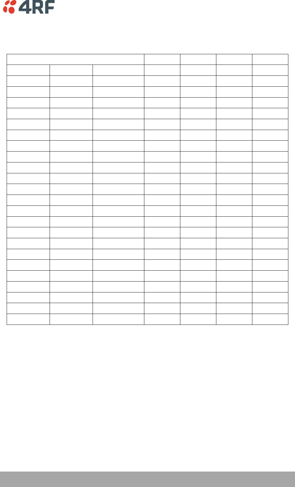
Specifications | 389
Aprisa SR+ User Manual 1.6.0 PO
Receiver
Receiver Sensitivity
12.5 kHz
25 kHz
50 kHz
75 kHz
BER < 10-2
64 QAM
Max coded FEC
-106 dBm
-102 dBm
-99 dBm
-96 dBm
BER < 10-2
64 QAM
Min coded FEC
-105 dBm
-101 dBm
-98 dBm
-95 dBm
BER < 10-2
64 QAM
No FEC
-103 dBm
-99 dBm
-96 dBm
-93 dBm
BER < 10-2
16 QAM
Max coded FEC
-113 dBm
-110 dBm
-107 dBm
-104 dBm
BER < 10-2
16 QAM
Min coded FEC
-112 dBm
-109 dBm
-106 dBm
-103 dBm
BER < 10-2
16 QAM
No FEC
-109 dBm
-106 dBm
-103 dBm
-100 dBm
BER < 10-2
QPSK
Max coded FEC
-118 dBm
-115 dBm
-112 dBm
-109 dBm
BER < 10-2
QPSK
Min coded FEC
-117 dBm
-114 dBm
-111 dBm
-108 dBm
BER < 10-2
QPSK
No FEC
-115 dBm
-112 dBm
-109 dBm
-106 dBm
BER < 10-2
4-CPFSK
Max coded FEC
NA
NA
NA
NA
BER < 10-2
4-CPFSK
Min coded FEC
-117 dBm
-114 dBm
-111 dBm
-108 dBm
BER < 10-2
4-CPFSK
No FEC
-115 dBm
-112 dBm
-109 dBm
-106 dBm
BER < 10-6
64 QAM
Max coded FEC
-103 dBm
-99 dBm
-96 dBm
-93 dBm
BER < 10-6
64 QAM
Min coded FEC
-101 dBm
-97 dBm
-94 dBm
-91 dBm
BER < 10-6
64 QAM
No FEC
-96 dBm
-92 dBm
-89 dBm
-86 dBm
BER < 10-6
16 QAM
Max coded FEC
-110 dBm
-107 dBm
-104 dBm
-101 dBm
BER < 10-6
16 QAM
Min coded FEC
-108 dBm
-105 dBm
-102 dBm
-99 dBm
BER < 10-6
16 QAM
No FEC
-102 dBm
-99 dBm
-96 dBm
-93 dBm
BER < 10-6
QPSK
Max coded FEC
-115 dBm
-112 dBm
-109 dBm
-106 dBm
BER < 10-6
QPSK
Min coded FEC
-113 dBm
-110 dBm
-107 dBm
-104 dBm
BER < 10-6
QPSK
No FEC
-108 dBm
-105 dBm
-102 dBm
-99 dBm
BER < 10-6
4-CPFSK
Max coded FEC
NA
NA
NA
NA
BER < 10-6
4-CPFSK
Min coded FEC
-113 dBm
-110 dBm
-107 dBm
-104 dBm
BER < 10-6
4-CPFSK
No FEC
-108 dBm
-105 dBm
-102 dBm
-99 dBm
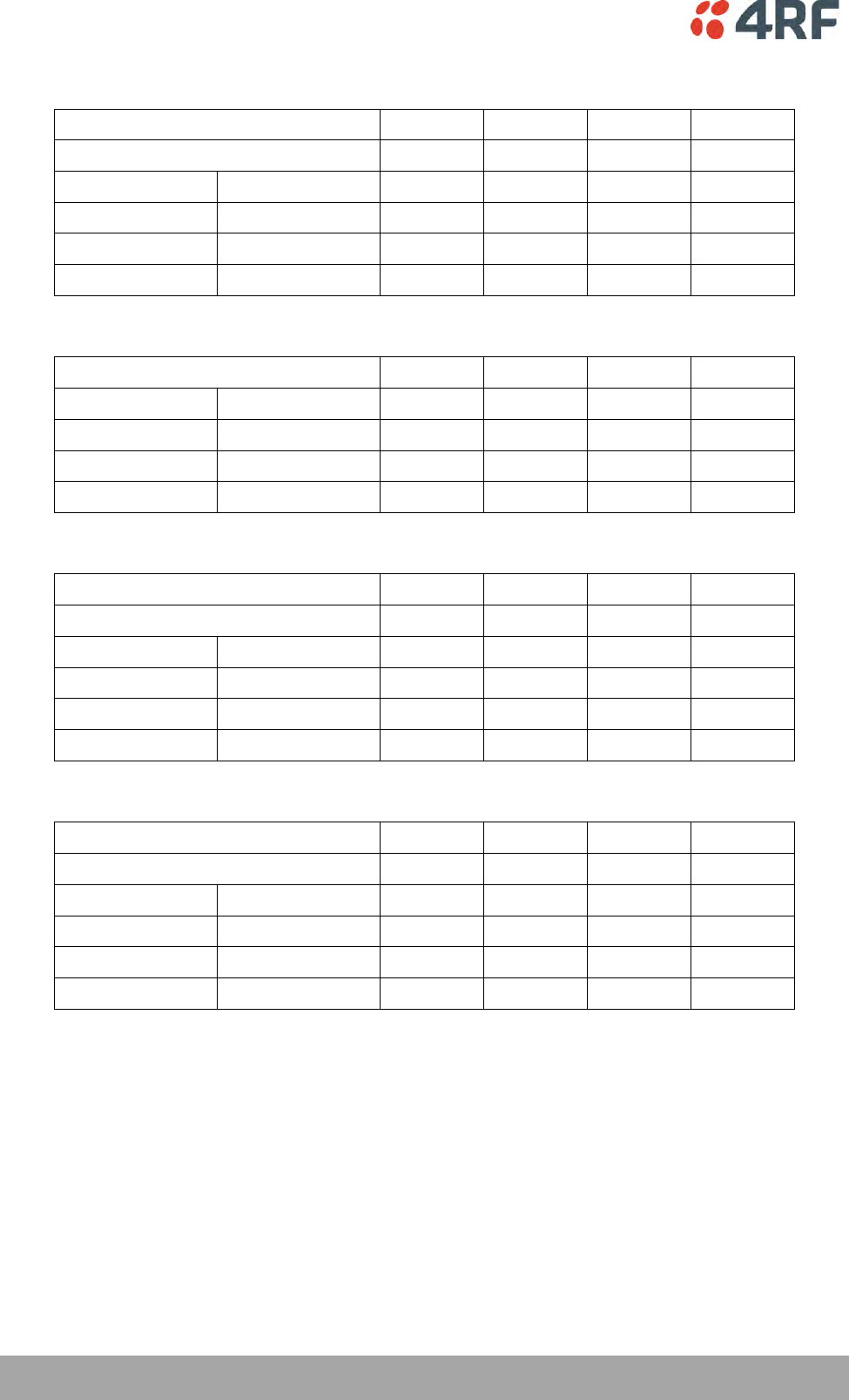
390 | Specifications
Aprisa SR+ User Manual 1.6.0 PO
Adjacent Channel Selectivity
12.5 kHz
25 kHz
50 kHz
75 kHz
Adjacent channel selectivity
> -47 dBm
> -37 dBm
> -37 dBm
> -37 dBm
BER < 10-2
64 QAM
> 43 dB
> 53 dB
> 53 dB
> 53 dB
BER < 10-2
16 QAM
> 43 dB
> 53 dB
> 53 dB
> 53 dB
BER < 10-2
QPSK
> 48 dB
> 58 dB
> 58 dB
> 58 dB
BER < 10-2
4-CPFSK
> 55 dB
> 65 dB
> 65 dB
> 65 dB
Co-Channel Rejection
12.5 kHz
25 kHz
50 kHz
75 kHz
BER < 10-2
64 QAM
> –23 dB
> –23 dB
> –23 dB
> –23 dB
BER < 10-2
16 QAM
> –19 dB
> –19 dB
> –19 dB
> –19 dB
BER < 10-2
QPSK
> –12 dB
> –12 dB
> –12 dB
> –12 dB
BER < 10-2
4-CPFSK
> –17 dB
> –17 dB
> –17 dB
> –17 dB
Intermodulation Response Rejection
12.5 kHz
25 kHz
50 kHz
75 kHz
Intermodulation response rejection
> -35 dBm
> -35 dBm
> -35 dBm
> -35 dBm
BER < 10-2
64 QAM
> 55 dB
> 55 dB
> 55 dB
> 55 dB
BER < 10-2
16 QAM
> 55 dB
> 55 dB
> 55 dB
> 55 dB
BER < 10-2
QPSK
> 60 dB
> 60 dB
> 60 dB
> 60 dB
BER < 10-2
4-CPFSK
> 65 dB
> 65 dB
> 65 dB
> 65 dB
Blocking or Desensitization
12.5 kHz
25 kHz
50 kHz
75 kHz
Blocking or desensitization
> -17 dBm
> -17 dBm
> -17 dBm
> -17 dBm
BER < 10-2
64 QAM
> 73 dB
> 73 dB
> 73 dB
> 73 dB
BER < 10-2
16 QAM
> 73 dB
> 73 dB
> 73 dB
> 73 dB
BER < 10-2
QPSK
> 78 dB
> 78 dB
> 78 dB
> 78 dB
BER < 10-2
4-CPFSK
> 85 dB
> 85 dB
> 85 dB
> 85 dB

Specifications | 391
Aprisa SR+ User Manual 1.6.0 PO
Spurious Response Rejection
12.5 kHz
25 kHz
50 kHz
75 kHz
Spurious response rejection
> -32 dBm
> -32 dBm
> -32 dBm
> -32 dBm
BER < 10-2
64 QAM
> 58 dB
> 58 dB
> 58 dB
> 58 dB
BER < 10-2
16 QAM
> 58 dB
> 58 dB
> 58 dB
> 58 dB
BER < 10-2
QPSK
> 63 dB
> 63 dB
> 63 dB
> 63 dB
BER < 10-2
4-CPFSK
> 70 dB
> 70 dB
> 70 dB
> 70 dB
Receiver Spurious Radiation
12.5 kHz
25 kHz
50 kHz
75 kHz
Receiver spurious radiation
> -57 dBm
> -57 dBm
> -57 dBm
> -57 dBm
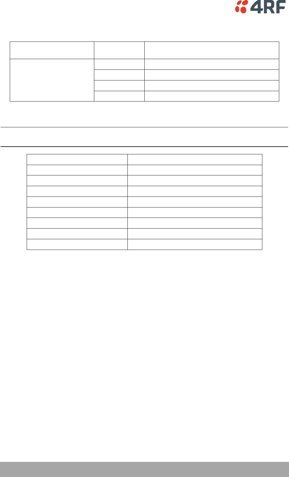
392 | Specifications
Aprisa SR+ User Manual 1.6.0 PO
Transmitter
Max peak envelope power
(PEP)
12.5 W (+41 dBm)
Average Power output
64 QAM
0.01 to 2.5 W (+10 to +34 dBm, in 1 dB steps)
16 QAM
0.01 to 3.2 W (+10 to +35 dBm, in 1 dB steps)
QPSK
0.01 to 5.0 W (+10 to +37 dBm, in 1 dB steps)
4-CPFSK (Note 1)
0.01 to 10.0 W (+10 to +40 dBm, in 1 dB steps)
Note 1: Please consult 4RF for availability
Note: The Aprisa SR+ transmitter contains power amplifier protection which allows the antenna to be
disconnected from the antenna port without product damage.
Adjacent channel power
< - 60 dBc
Transient adjacent channel power
< - 60 dBc
Spurious emissions
< - 37 dBm
Attack time
< 1.5 ms
Release time
< 0.5 ms
Data turnaround time
< 2 ms
Frequency stability
± 1.0 ppm
Frequency aging
< 1 ppm / annum
Emission Designator Suffix
QPSK G1D, QAM D1D

Specifications | 393
Aprisa SR+ User Manual 1.6.0 PO
Modem
Forward Error Correction
Variable length concatenated Reed Solomon
plus convolutional code
Adaptive Burst Support
Adaptive FEC
Adaptive Coding and Modulation
Data Payload Security
Data payload security
CCM* Counter with CBC-MAC
Data encryption
Counter Mode Encryption (CTR) using Advanced
Encryption Standard (AES) 128, 192 or 256
Data authentication
Cipher Block Chaining Message Authentication
Code (CBC-MAC) using Advanced Encryption
Standard (AES) 128, 192 or 256
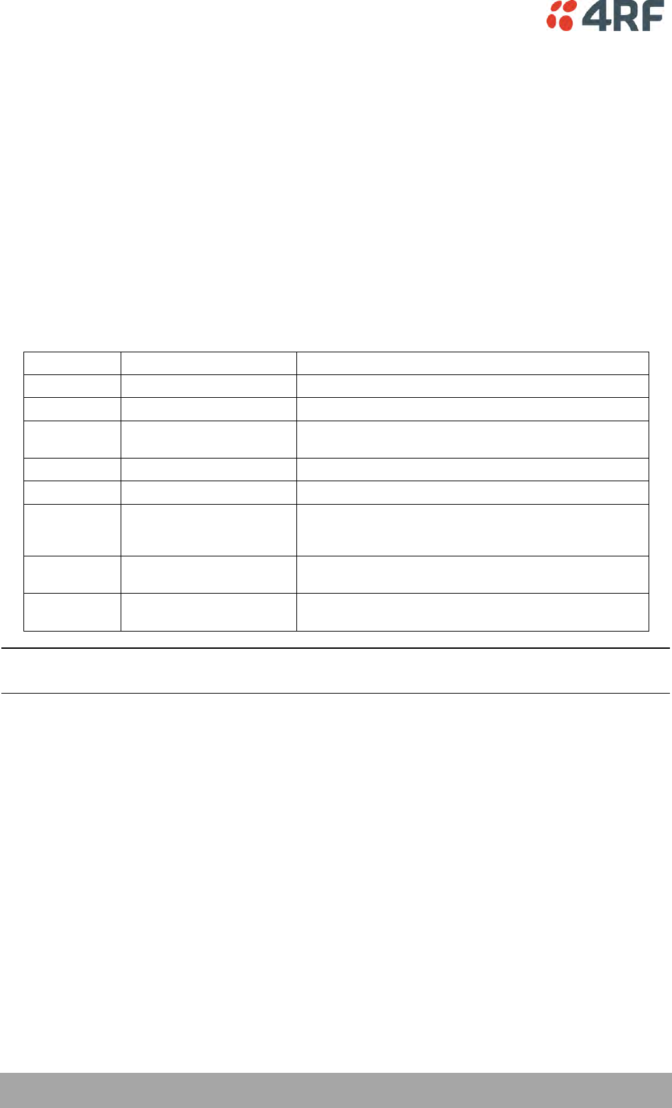
394 | Specifications
Aprisa SR+ User Manual 1.6.0 PO
Interface Specifications
Ethernet Interface
The Aprisa SR+ radio features an integrated 10Base-T/100Base-TX layer-2 Ethernet switch.
To simplify network setup, each port supports auto-negotiation and auto-sensing MDI/MDIX. Operators can
select from the following preset modes:
Auto negotiate
10Base-T half or full duplex
100Base-TX half or full duplex
The Ethernet ports are IEEE 802.3-compatible. The L2 Bridge (Switch) is IEEE 802.1d/q/p compatible, and
supports VLANs and VLAN manipulation of add/remove VLANs.
General
Interface
RJ45 x 2 (Integrated 2-port switch)
Cabling
CAT-5/6 UTP, supports auto MDIX (Standard Ethernet)
Maximum line length
100 metres on cat-5 or better
Bandwidth allocation
The Ethernet capacity maximum is determined by the
available radio link capacity.
Maximum transmission unit
Option setting of 1522 or 1536 octets
Address table size
1024 MAC addresses
Ethernet mode
10Base-T or 100Base-TX
Full duplex or half duplex
(Auto-negotiating and auto-sensing)
Diagnostics
Left Green LED
Off: no Ethernet signal received
On: Ethernet signal received
Right Orange LED
Off: no data present on the interface
Flashing: data present on the interface
Note: Do not connect Power over Ethernet (PoE) connections to the Aprisa SR+ Ethernet ports as this will
damage the port.
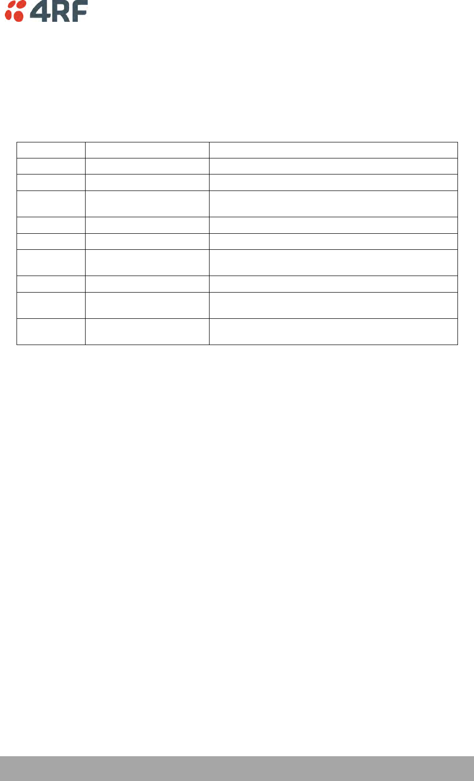
Specifications | 395
Aprisa SR+ User Manual 1.6.0 PO
RS-232 Asynchronous Interface
The Aprisa SR+ radio’s ITU-T V.24 compliant RS-232 interface is configured as a Cisco® pinout DCE. The
interface terminates to a DTE using a straight-through cable or to a DCE with a crossover cable (null
modem).
The interface uses two handshaking control lines between the DTE and the DCE.
General
Interface
ITU-T V.24 / EIA/TIA RS-232E
Interface direction
DCE only
Maximum line length
10 metres (dependent on baud rate)
Async
parameters
Standard mode data bits
7 or 8 bits
Standard mode parity
Configurable for None, Even or Odd
Standard mode stop bits
1 or 2 bits
Interface baud rates
300, 600, 1200, 2400, 4800, 9600, 19200, 38400, 57600 and
115200 bit/s
Control signals
DCE to DTE
CTS, RTS, DSR, DTR
Diagnostics
Left Green LED
Off: no RS-232 device connected
On: RS-232 device connected
Right Orange LED
Off: no data present on the interface
Flashing: data present on the interface
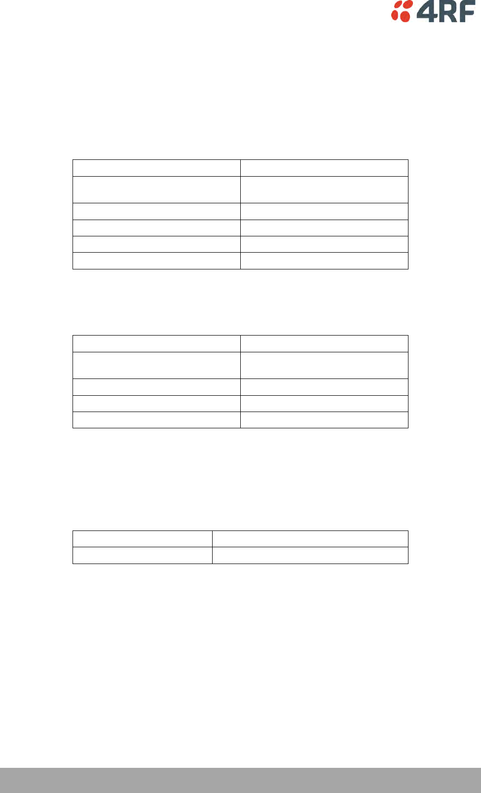
396 | Specifications
Aprisa SR+ User Manual 1.6.0 PO
Hardware Alarms Interface
The hardware alarms interface supports two alarm inputs and two alarms outputs.
Alarm Inputs
The alarm connector provides two hardware alarm inputs for alarm transmission to the other radios in the
network.
Interface
RJ45 connector
Detector type
Non-isolated ground referenced voltage
detector
Detection voltage - on
> +10 VDC
Detection voltage - off
< +4 VDC
Maximum applied input voltage
30 VDC
Maximum input current limit
10 mA
Alarm Outputs
The alarm connector provides two hardware alarm outputs for alarm reception from other radios in the
network.
Interface
RJ45 connector
Output type
Non-isolated ground referenced open
collector output
Maximum applied voltage
30 VDC
Maximum drive current
100 mA
Overload protection
Thermally resettable fuse
Protect Interface
The Protect interface is used to connect the radios to the protection switch within a Protected Station. It
is not a customer interface.
Protection Switch Specifications
RF Insertion Loss
< 0.5 dB (switch and connecting cables)
Remote Control inputs
Logic 4700 ohms pullup to +3.3 VDC

Specifications | 397
Aprisa SR+ User Manual 1.6.0 PO
Power Specifications
Power Supply
Aprisa SR+ Radio
Nominal voltage
+13.8 VDC (negative earth)
Absolute input voltage range
+10 to +30 VDC
Maximum power input
35 W
Connector
Molex 2 pin male screw fitting
39526-4002
Aprisa SR+ Protected Station
Power Input
13.8 VDC
48 VDC
Nominal voltage
+13.8 VDC (negative
earth)
48 VDC (floating)
Absolute input voltage range
+10 to +30 VDC
18 to 60 VDC
Maximum power input
42 W
Connector
2x Molex 2 pin male screw fitting
39526-4002
Aprisa SR+ Migration Master Station
Power Input
13.8 VDC
48 VDC
Nominal voltage
+13.8 VDC (negative
earth)
48 VDC (floating)
Absolute input voltage range
+10 to +30 VDC
18 to 60 VDC
Maximum power input
48 W
Connector
4x Molex 2 pin male screw fitting
39526-4002
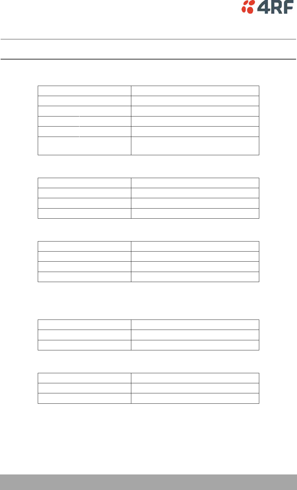
398 | Specifications
Aprisa SR+ User Manual 1.6.0 PO
Power Consumption
Note: The radio power consumption is very dependent on transmitter power, the type of traffic and
network activity.
Aprisa SR+ Radio
Mode
Power Consumption
Transmit / Receive
< 35 W for 10 W transmit peak power
< 25.0 W for 1 W transmit power
Receive only
Standard
< 7 W
Power Optimized
< 3 W in active receive state
< 2 W in idle receive state
< 0.5 W in sleep mode
Aprisa SR+ Protected Station and Aprisa SR+ Data Driven Protected Station
Mode
Power Consumption
Transmit / Receive
< 42 W for 10 W transmit peak power
< 32.0 W for 1 W transmit power
Receive only
< 15 W
Aprisa SR+ Migration Master Station
Mode
Power Consumption
Transmit / Receive
< 48 W for 10 W transmit peak power
< 38.0 W for 1 W transmit power
Receive only
< 21 W
Power Dissipation
Aprisa SR+ Radio
Transmit Power
Power Dissipation
10 W transmit power
< 25 W
1 W transmit power
< 24 W
Aprisa SR+ Protected Station and Aprisa SR+ Data Driven Protected Station
Transmit Power
Power Dissipation
10 W transmit power
< 32 W
1 W transmit power
< 31 W
Specifications | 399
Aprisa SR+ User Manual 1.6.0 PO
General Specifications
Environmental
Operating temperature range
-40 to +70˚ C (-40 to +158˚ F)
Storage temperature range
-40 to +80˚ C (-40 to +176˚ F)
Operating humidity
Maximum 95% non-condensing
Acoustic noise emission
No audible noise emission
Mechanical
Aprisa SR+ Radio
Dimensions
Width 210 mm (8.27”)
Depth 130 mm (5.12”) and 146 mm (5.748”)
with TNC connectors
Height 41.5 mm (1.63”)
Weight
1.25 kg (2.81 lbs)
Colour
Matt black
Mounting
Wall (2 x M5 screws)
Rack shelf (4 x M4 screws)
DIN rail bracket
Aprisa SR+ Protected Station
Dimensions
Width 432.6 mm (17”)
Depth 372 mm (14.6”) and 388 mm (15.276”)
with TNC connectors
Height 2U plus external duplexer (if used)
Weight
9.4 kg (22 lbs) (includes the 2 radios)
Colour
Matt black
Mounting
Rack mount (4 x M6 screws)
Aprisa SR+ Migration Master Station
Dimensions
Width 432.6 mm (17”)
Depth 372 mm (14.6”) and 388 mm (15.276”)
with TNC connectors
Height 3U plus external duplexer (if used)
Weight
13.8 kg (31 lbs) (includes the 2 radios)
Colour
Matt black
Mounting
Rack mount (8 x M6 screws)
400 | Specifications
Aprisa SR+ User Manual 1.6.0 PO
Compliance
ETSI
Radio
EN 300 113-2
EMI / EMC
EN 301 489-1 and 5
Safety
EN 60950-1:2006
Class 1 division 2 for hazardous locations
Environmental
ETS 300 019 Class 3.4
Ingress Protection IP51
FCC
Radio
47CFR part 24, part 27, part 90 and part 101
Private Land Mobile Radio Services
EMC
47CFR part 15 Radio Frequency Devices, EN
301 489-1 and 5
Safety
EN 60950-1:2006
Class 1 division 2 for hazardous locations
Environmental
ETS 300 019 Class 3.4
Ingress Protection IP51
IC
Radio
RSS-119 / RSS-134
EMC
This Class A digital apparatus complies with
Canadian standard ICES-003.
Cet appareil numérique de la classe A est
conforme à la norme NMB-003 du Canada.
Safety
EN 60950-1:2006
Class 1 division 2 for hazardous locations
Environmental
ETS 300 019 Class 3.4
Ingress Protection IP51

Product End Of Life | 401
Aprisa SR+ User Manual 1.6.0 PO
14. Product End Of Life
End-of-Life Recycling Programme (WEEE)
The WEEE Directive concerns the recovery, reuse, and recycling of electronic and electrical equipment.
Under the Directive, used equipment must be marked, collected separately, and disposed of properly.
4RF has implemented an end-of-life recycling programme to manage the reuse, recycling, and recovery of
waste in an environmentally safe manner using processes that comply with the WEEE Directive (EU Waste
Electrical and Electronic Equipment 2002/96/EC).
The WEEE Symbol Explained
This symbol appears on Electrical and Electronic Equipment (EEE) as part of the WEEE (Waste EEE)
directive. It means that the EEE may contain hazardous substances and must not be thrown away with
municipal or other waste.
WEEE Must Be Collected Separately
You must not dispose of electrical and electronic waste with municipal and other waste. You must
separate it from other waste and recycling so that it can be easily collected by the proper regional WEEE
collection system in your area.
YOUR ROLE in the Recovery of WEEE
By separately collecting and properly disposing of WEEE, you are helping to reduce the amount of WEEE
that enters the waste stream.
One of the aims of the WEEE directive is to divert EEE away from landfill and encourage recycling.
Recycling EEE means that valuable resources such as metals and other materials (which require energy to
source and manufacture) are not wasted. Also, the pollution associated with accessing new materials and
manufacturing new products is reduced.
EEE Waste Impacts the Environment and Health
Electrical and electronic equipment (EEE) contains hazardous substances which have potential effects on
the environment and human health. If you want environmental information on the Aprisa SR+ radio,
contact us (on page 15).

402 | Copyrights
Aprisa SR+ User Manual 1.6.0 PO
15. Copyrights
Mirrored Bits® is a registered trademark of Schweitzer Engineering Laboratories, Inc

Abbreviations | 403
Aprisa SR+ User Manual 1.6.0 PO
16. Abbreviations
AES Advanced Encryption Standard
AGC Automatic Gain Control
BER Bit Error Rate
CBC Cipher Block Chaining
CCM Counter with CBC-MAC integrity
DCE Data Communications Equipment
DTE Data Radio Equipment
EMC Electro-Magnetic Compatibility
EMI Electro-Magnetic Interference
ESD Electro-Static Discharge
ETSI European Telecommunications Standards
Institute
FW Firmware
HW Hardware
IF Intermediate Frequency
IP Internet Protocol
I/O Input/Output
ISP Internet Service Provider
kbit/s Kilobits per second
kHz Kilohertz
LAN Local Area Network
LED Light Emitting Diode
mA Milliamps
MAC Media Access Control
MAC Message Authentication Code
Mbit/s Megabits per second
MHz Megahertz
MIB Management Information Base
MTBF Mean Time Between Failures
MTTR Mean Time To Repair
ms milliseconds
NMS Network Management System
PC Personal Computer
PCA Printed Circuit Assembly
PLL Phase Locked Loop
ppm Parts Per Million
PMR Public Mobile Radio
RF Radio Frequency
RoHS Restriction of Hazardous Substances
RSSI Received Signal Strength Indication
RX Receiver
SNMP Simple Network Management Protocol
SNR Signal to Noise Ratio
SWR Standing Wave Ratio
TCP/IP Transmission Control Protocol/Internet
Protocol
TCXO Temperature Compensated Crystal Oscillator
TFTP Trivial File Transfer Protocol
TMR Trunk Mobile Radio
TX Transmitter
UTP Unshielded Twisted Pair
VAC Volts AC
VCO Voltage Controlled Oscillator
VDC Volts DC
WEEE Waste Electrical and Electronic Equipment