4RF SR135M130 VHF POINT TO POINT DIGITAL TRANSCEIVER User Manual Aprisa SR Product Description
4RF Limited VHF POINT TO POINT DIGITAL TRANSCEIVER Aprisa SR Product Description
4RF >
Contents
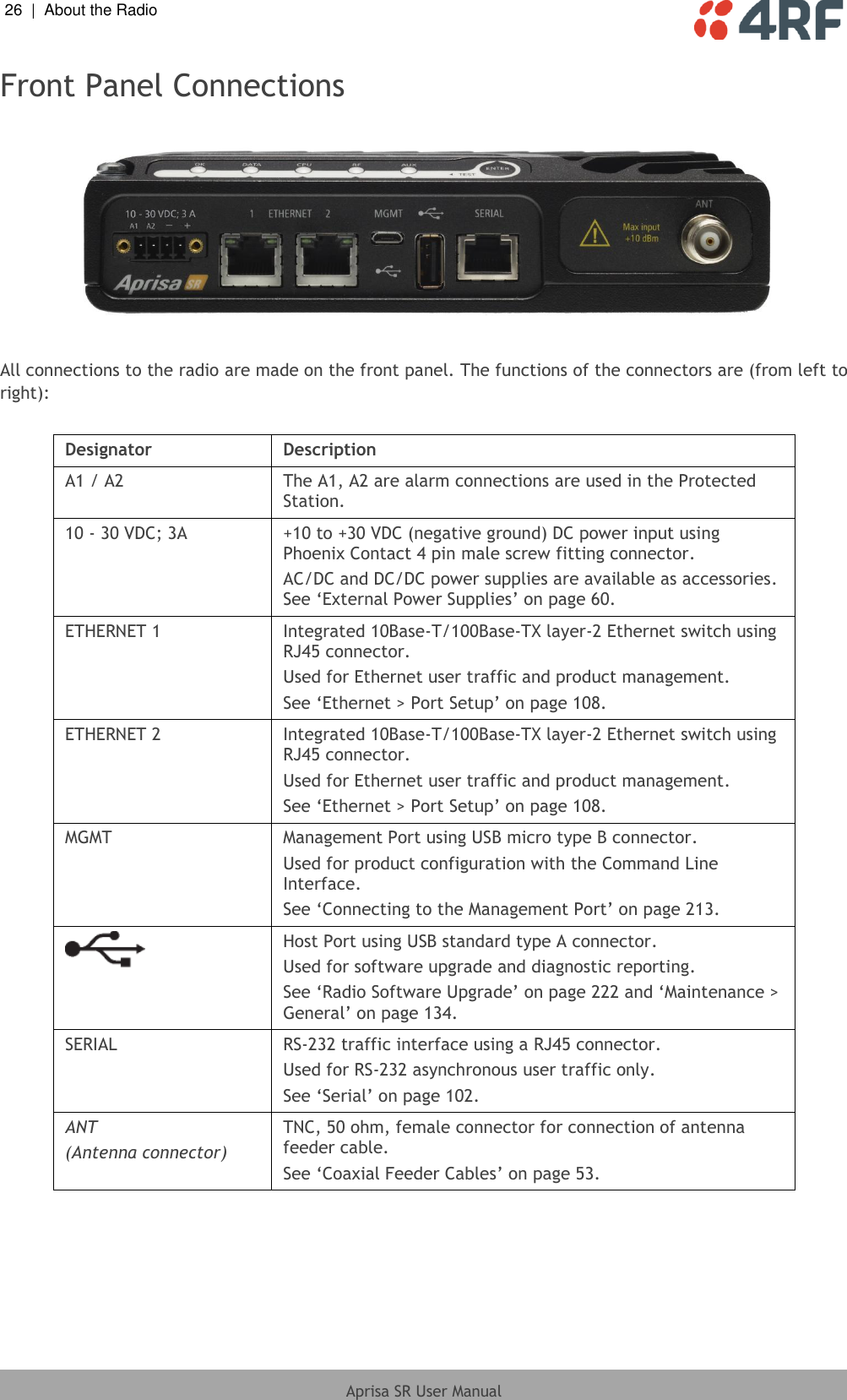
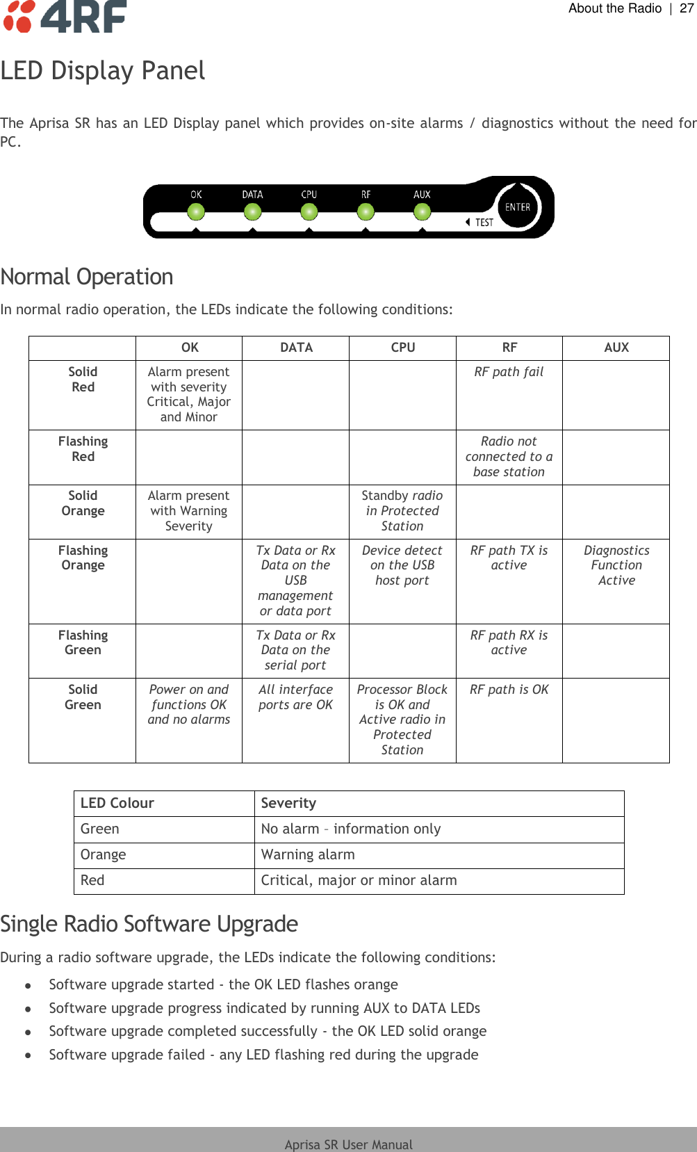
- 1. User Manual 1
- 2. User Manual 2
User Manual 1