4RF SRN0400012A Aprisa SR SRN400-000 User Manual
4RF Limited Aprisa SR SRN400-000
UserManual.wiki
>
4RF
>
SRN0400012A User Manual
User Manual
Navigation menu
Upload a User Manual
Namespaces
Wiki Guide
HTML
PDF
Info
Views
User Manual
Discussion / Help
Navigation
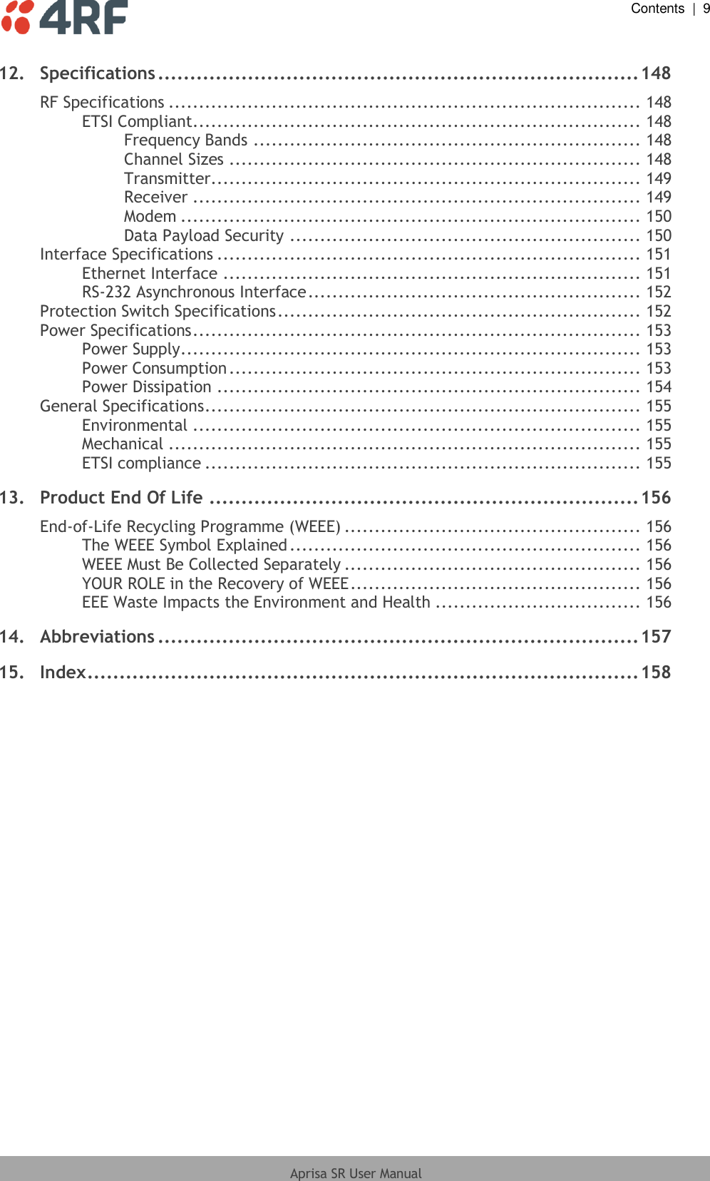

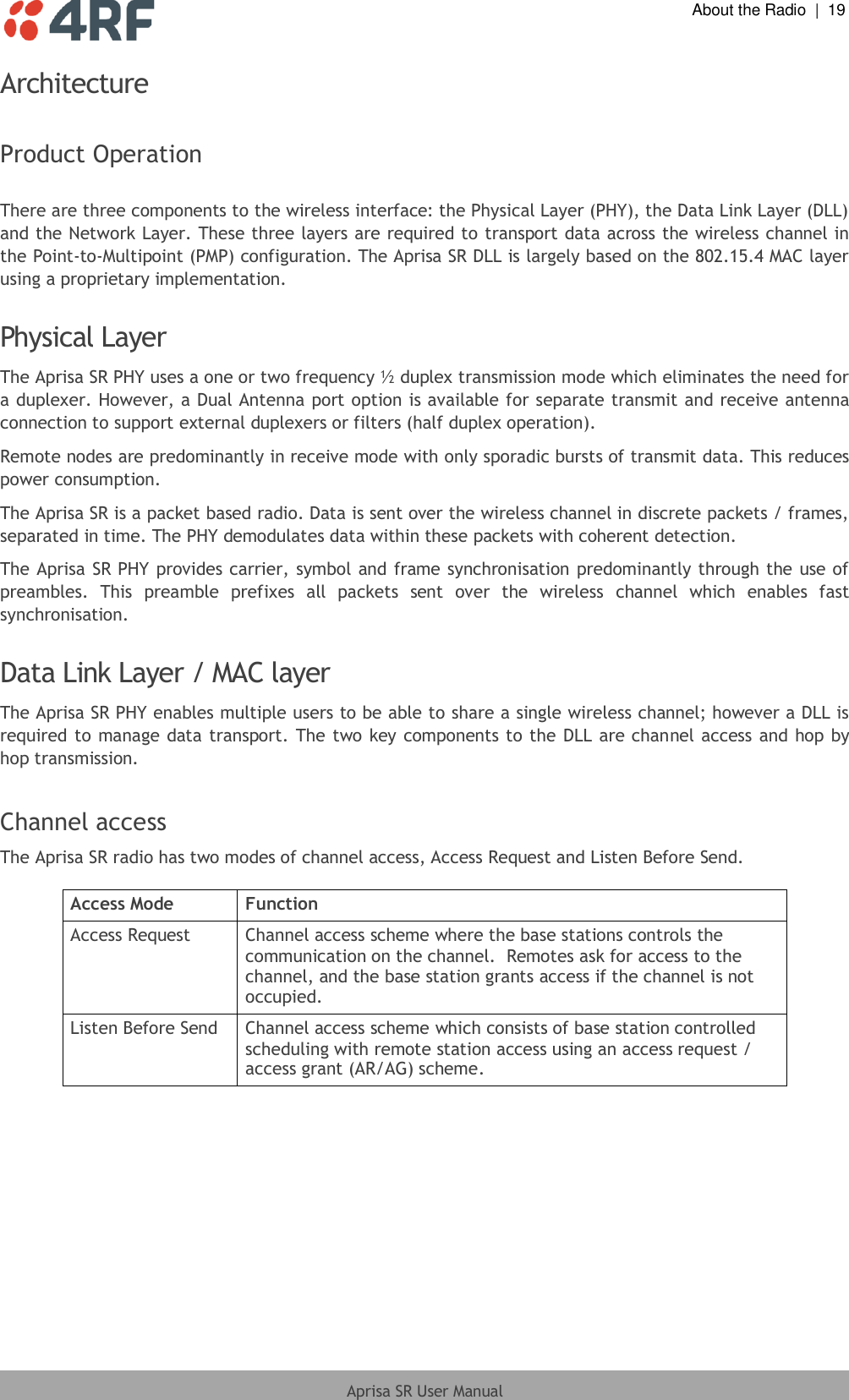
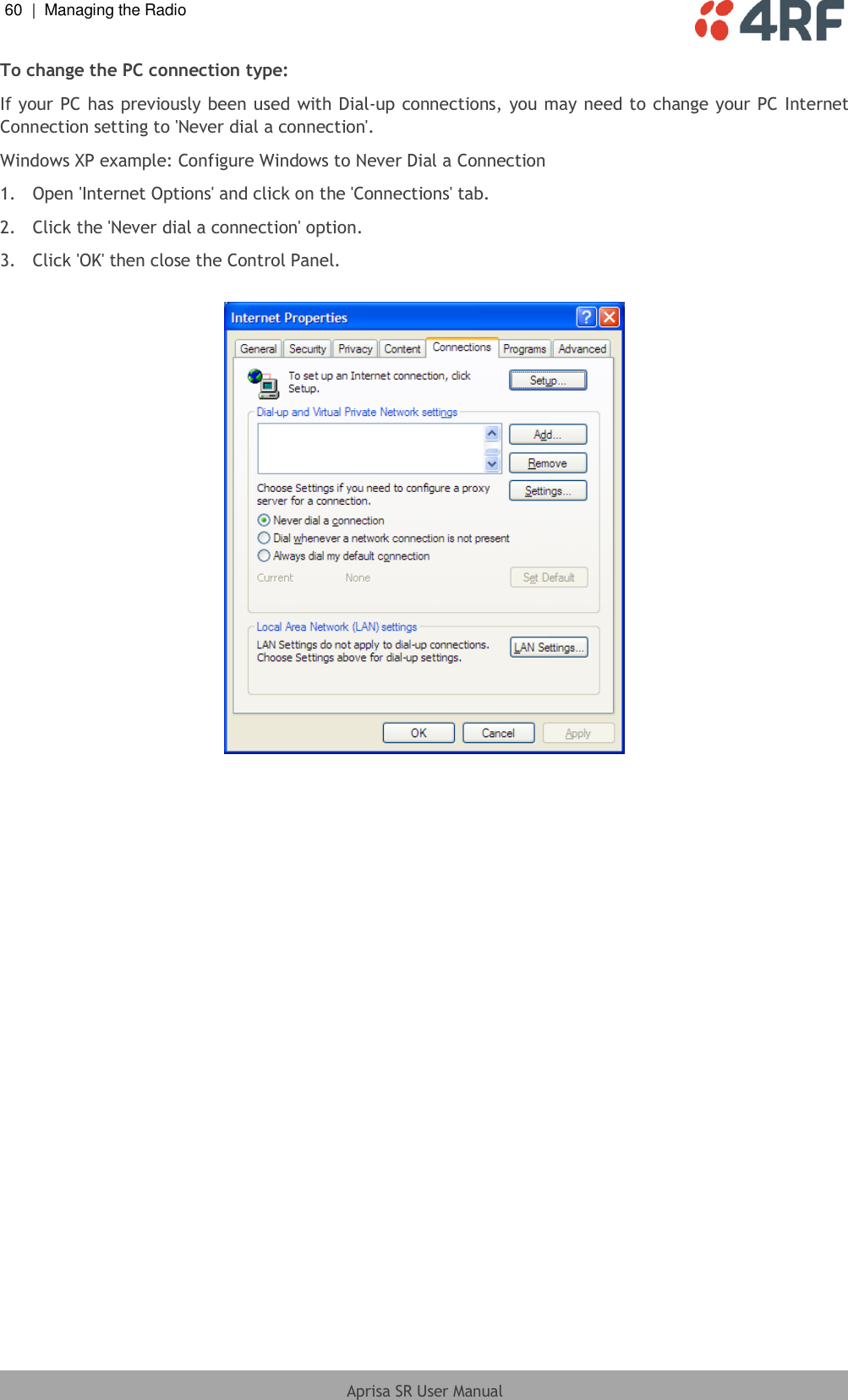
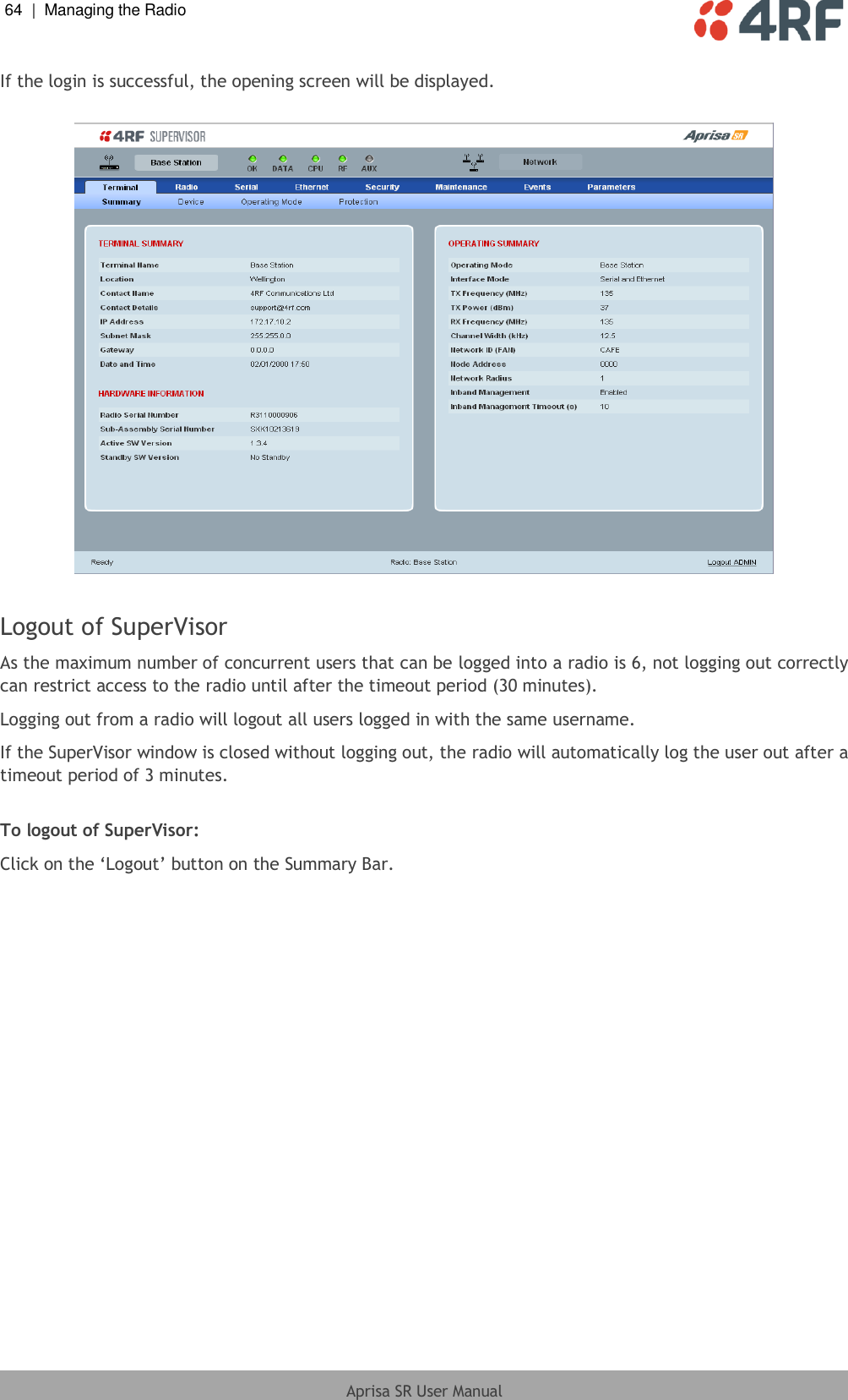
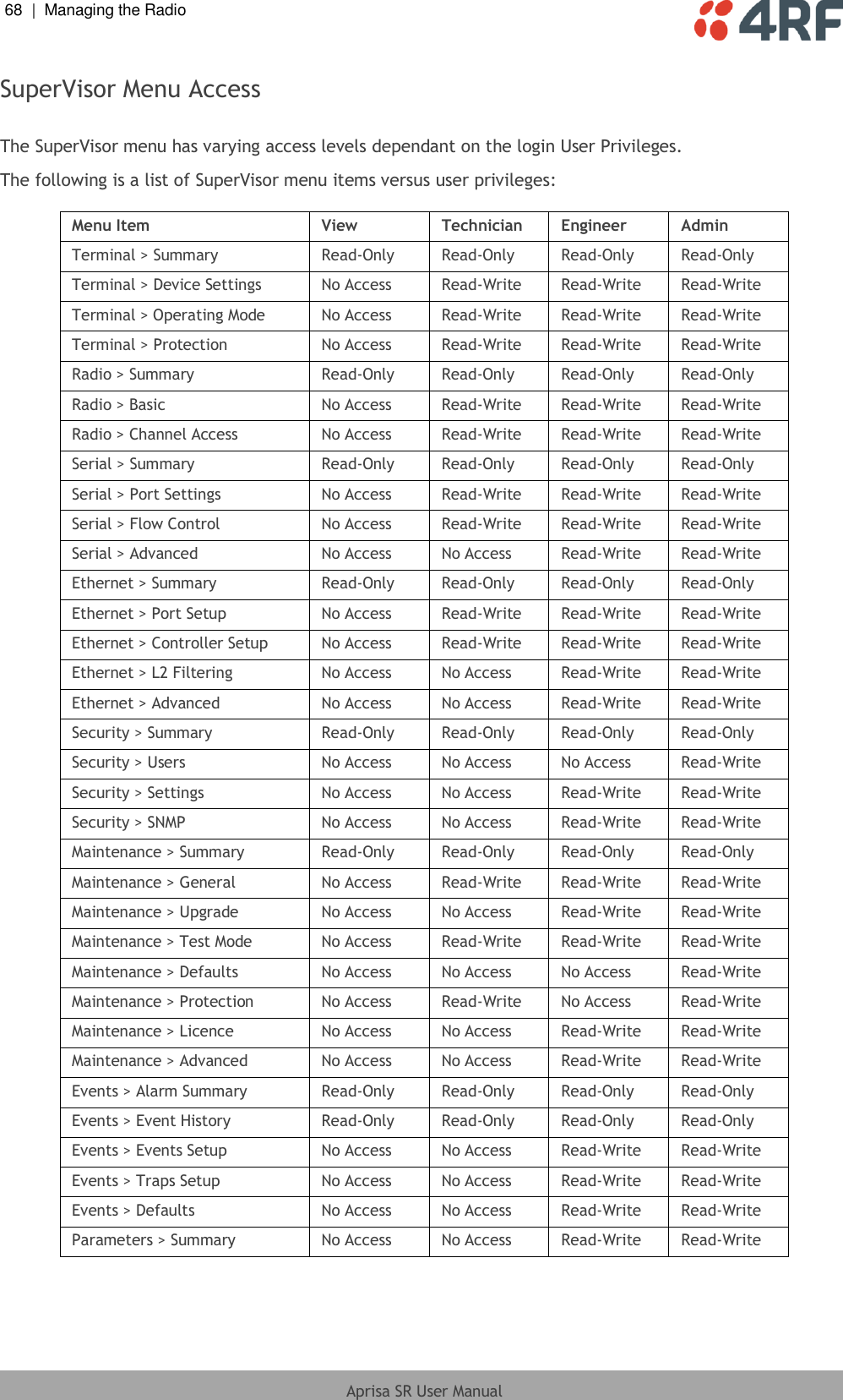
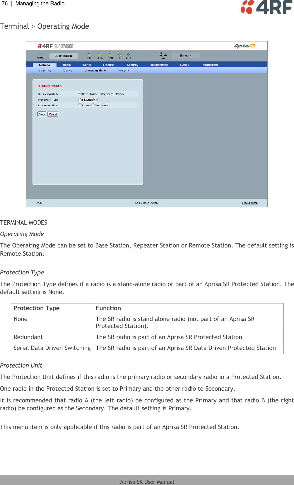
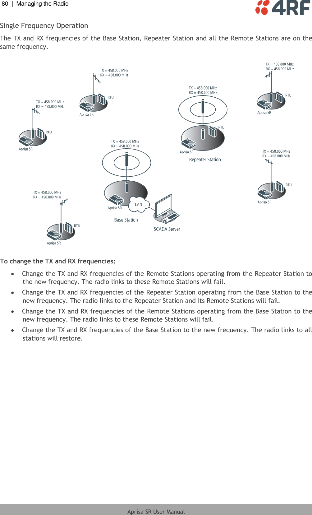
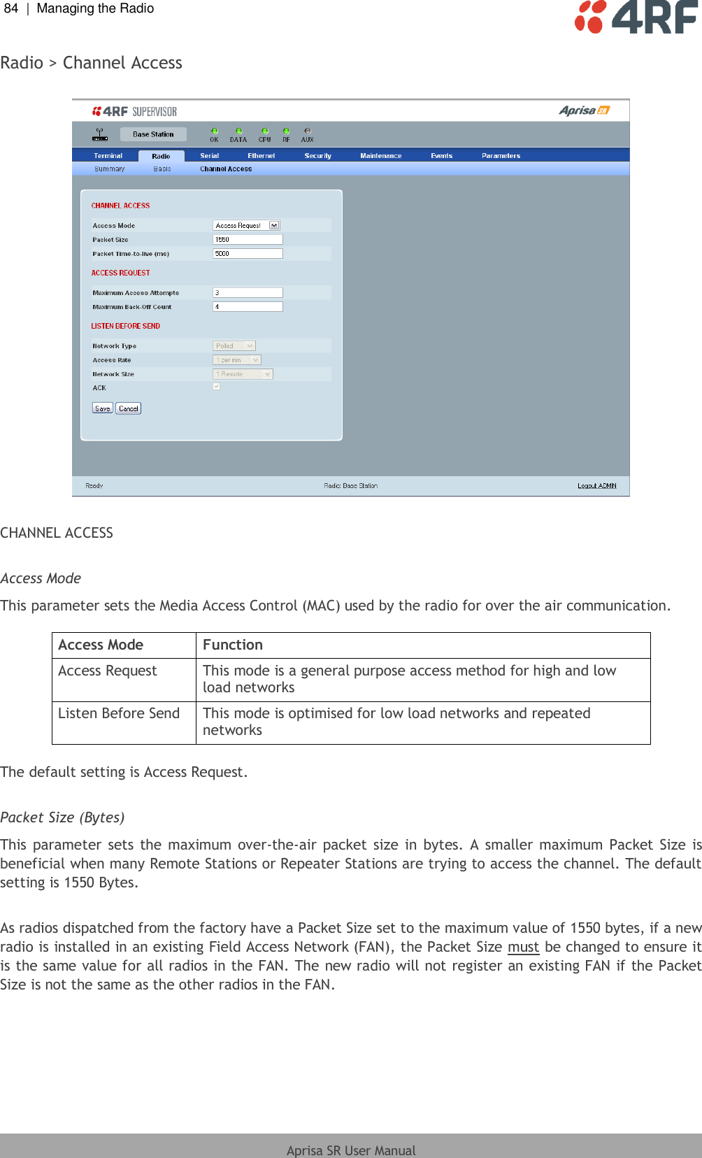
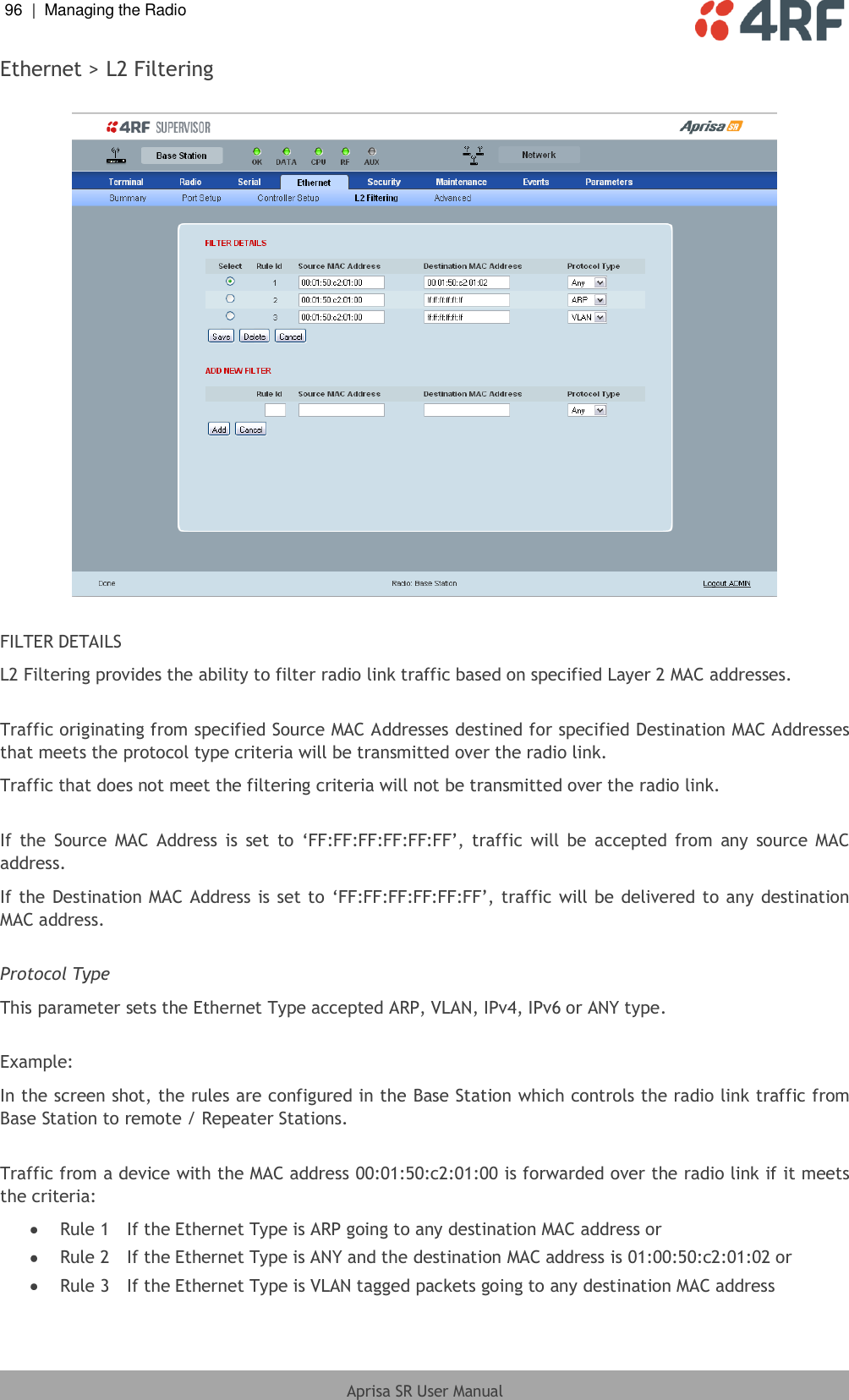
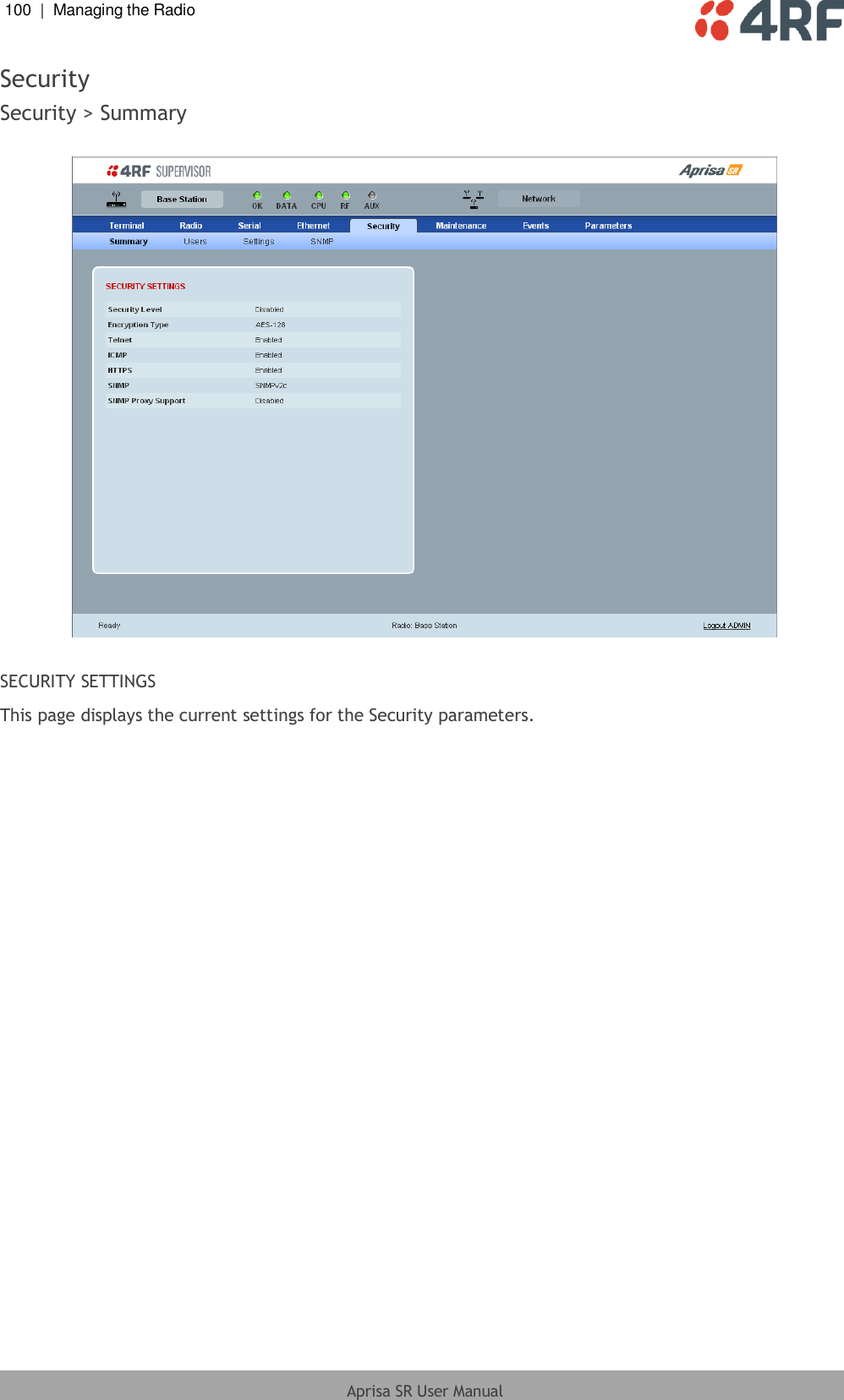
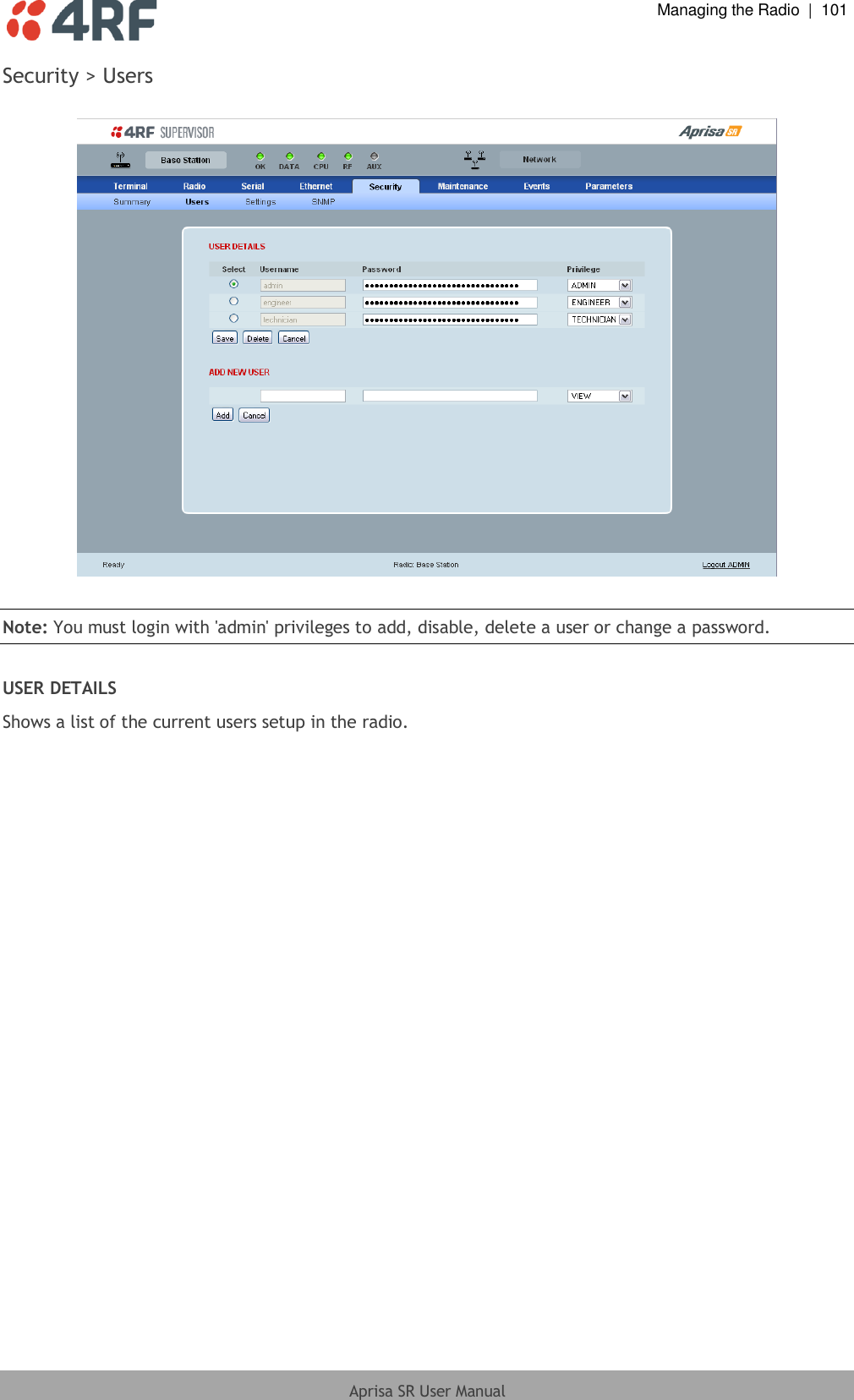
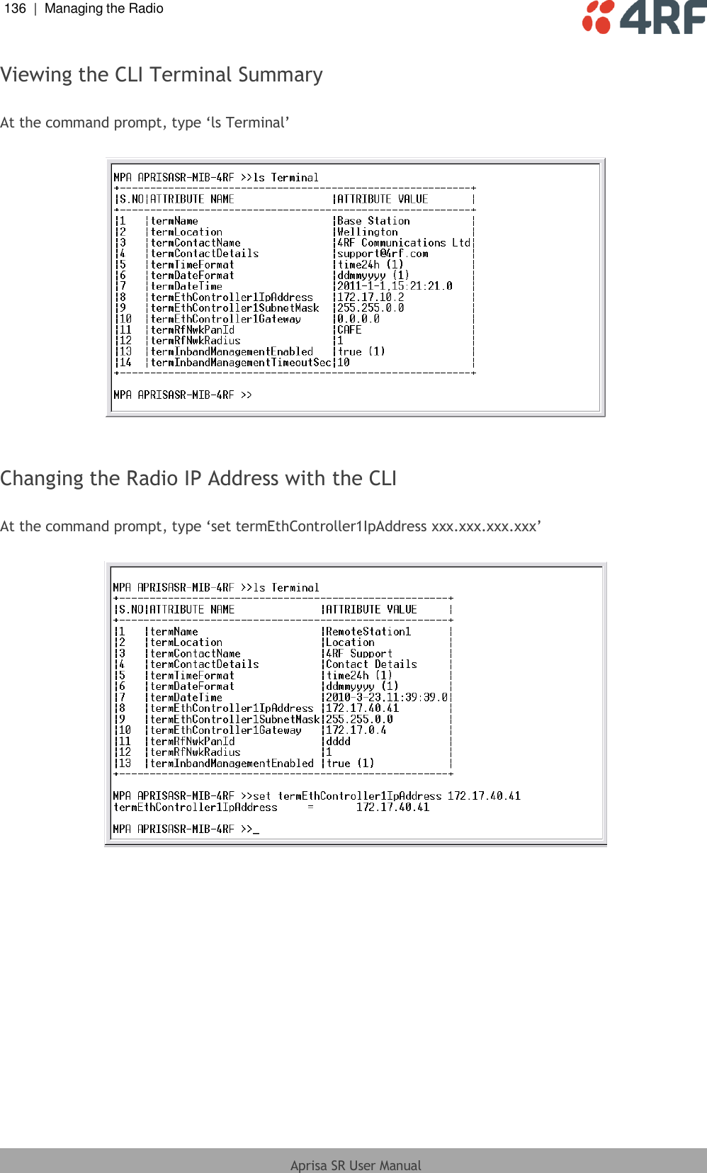
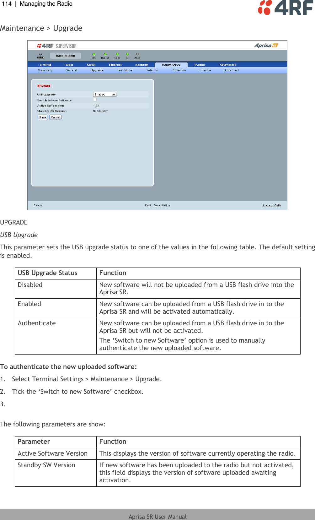
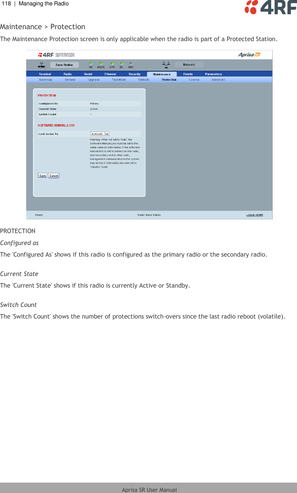
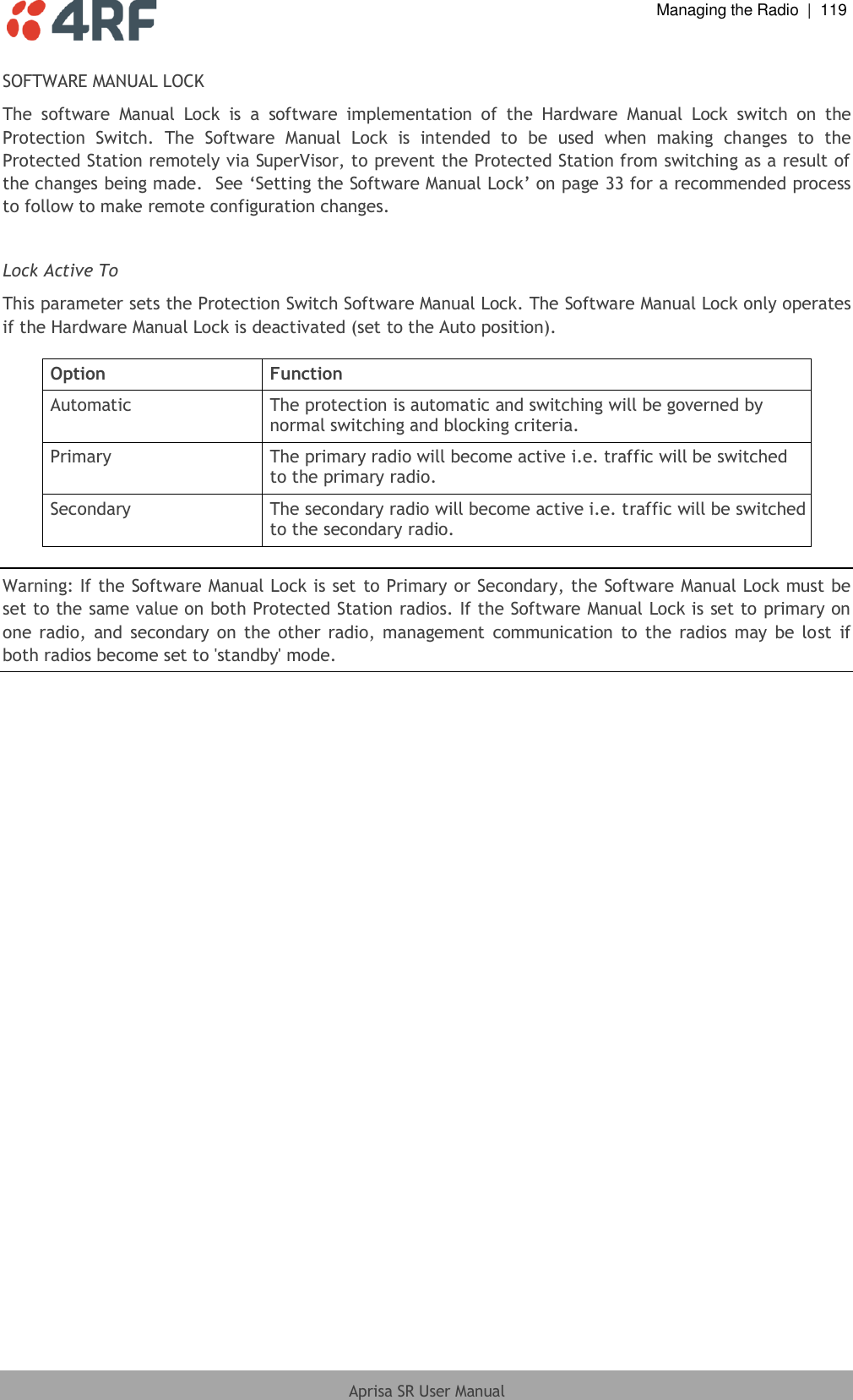
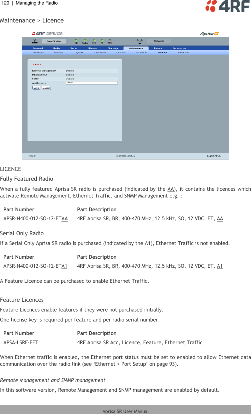
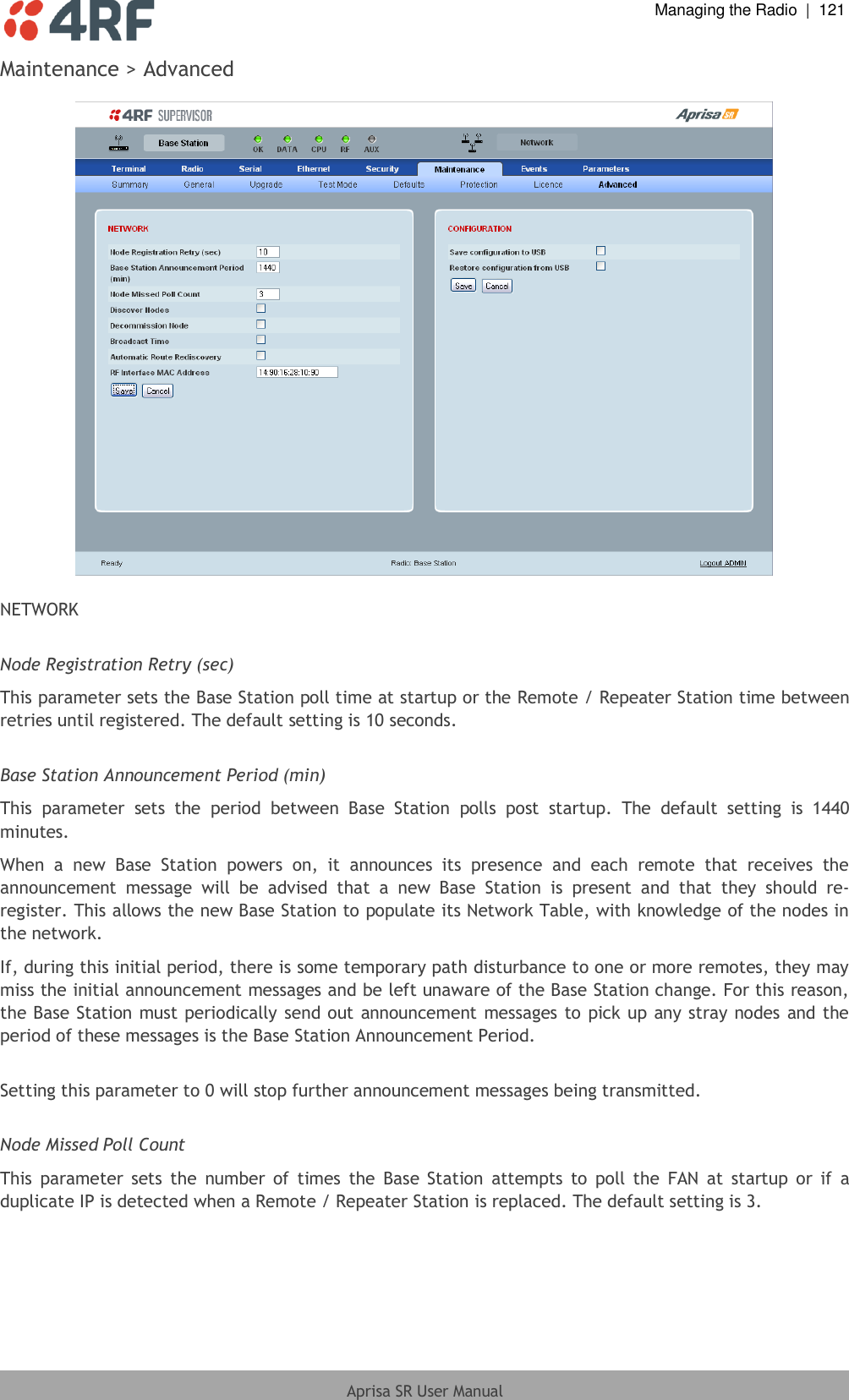
![102 | Managing the Radio Aprisa SR User Manual ADD NEW USER 1. Enter the Username. A username can be up to 32 characters but cannot contain back slashes, forward slashes, spaces, tabs, single or double quotes. Usernames are case sensitive. 2. Enter the Password. A password can be up to 32 characters but cannot contain back slashes, forward slashes, spaces, tabs, single or double quotes. Passwords are case sensitive. Good password policy: contains at least eight characters, and contains at least one upper case letter, and contains at least one lower case letter, and contains at least one digit or another character such as !@#$%^&(){}[]<>... , and is not a term in a familiar language or jargon, and is not identical to or derived from the accompanying account name, from personal characteristics or from information from one’s family/social circle, and is easy to remember, for instance by means of a key sentence, and can be typed in fluently. 3. Select the User Privileges There are four pre-defined User Privilege settings to allocate access rights to users. These user privileges have associated default usernames and passwords of the same name. The default login is ‘admin’. This login has full access to all radio parameters including the ability to add and change users. There can only be a maximum of two usernames with admin privileges and the last username with admin privileges cannot be deleted. User Privilege Default Username Default Password User Privileges View view view Users in this group can only view the summary pages. Technician technician technician Users in this group can view and edit parameters except Security > Users, Security > Settings and Advanced settings. Engineer engineer engineer Users in this group can view and edit parameters except Security > Users. Admin admin admin Users in this group can view and edit all parameters. See ‘SuperVisor Menu Access’ on page 68 for the list of SuperVisor menu items versus user privileges. 4. Click ‘Add’](https://usermanual.wiki/4RF/SRN0400012A/User-Guide-1633555-Page-105.png)
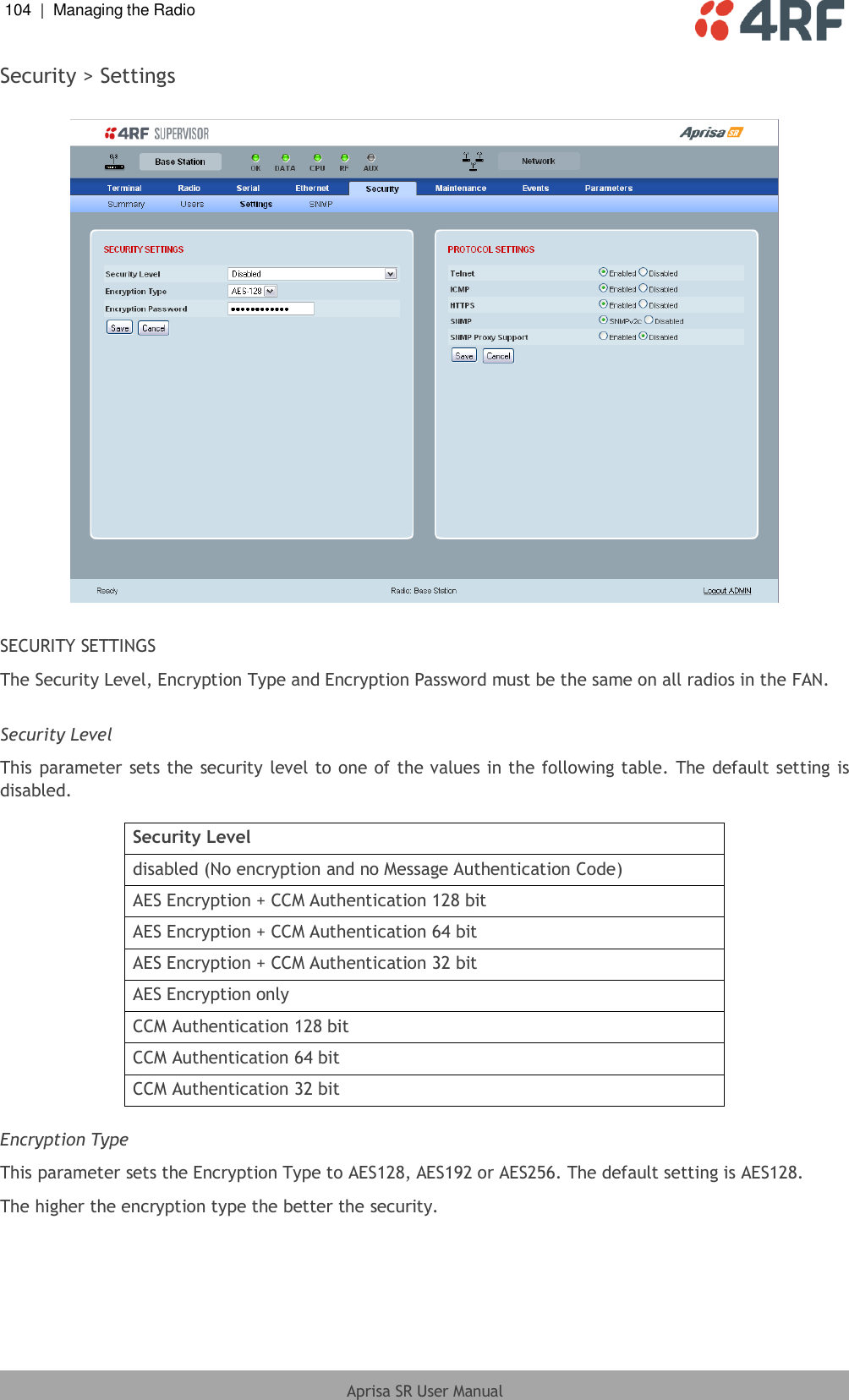
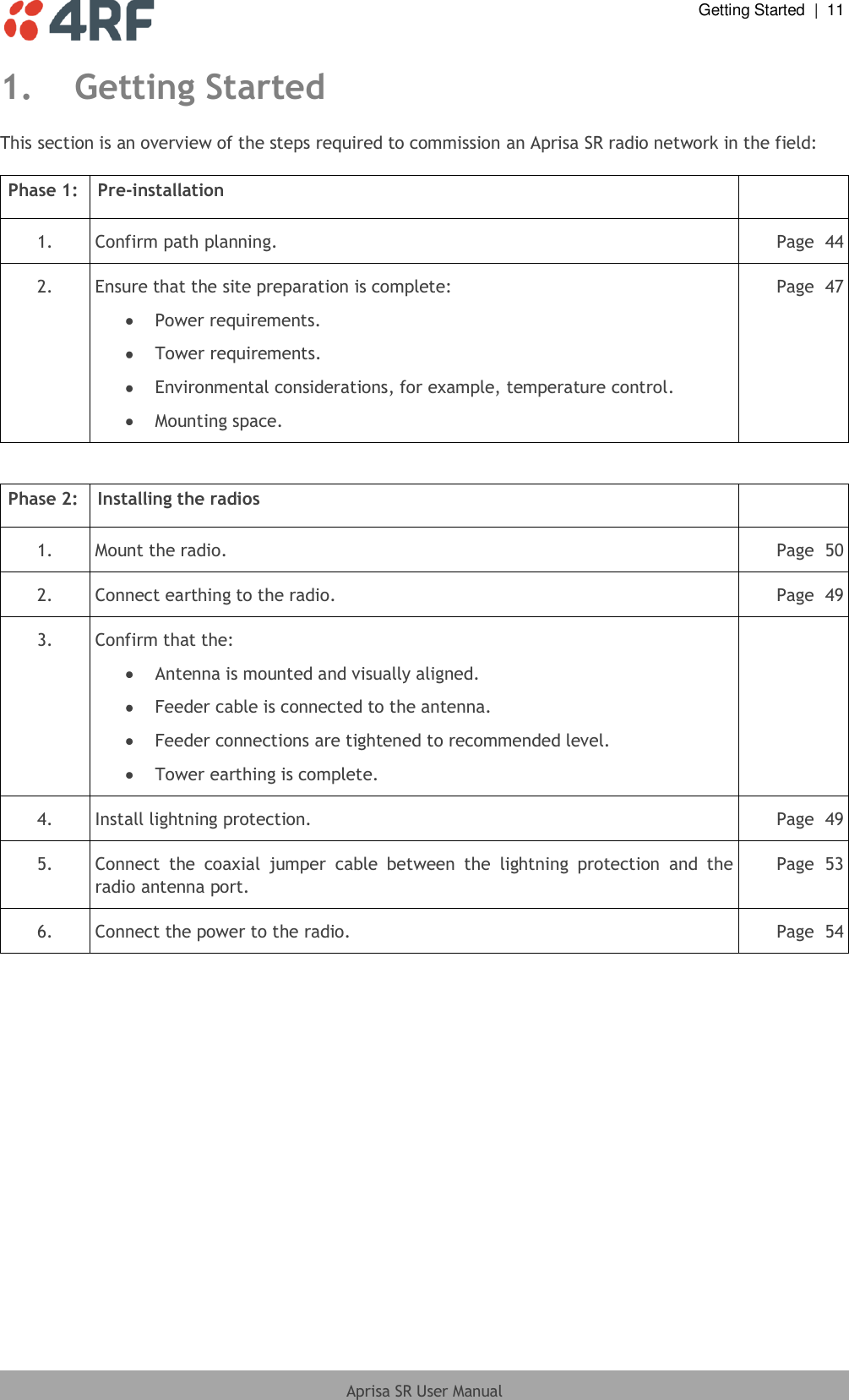
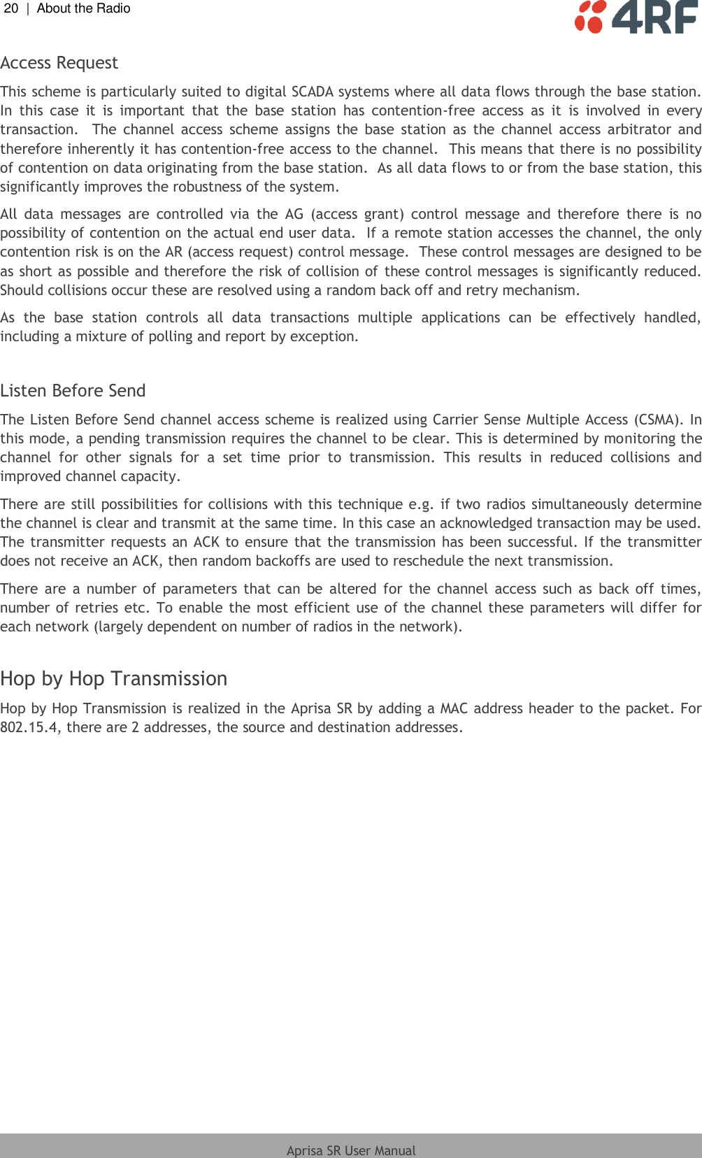
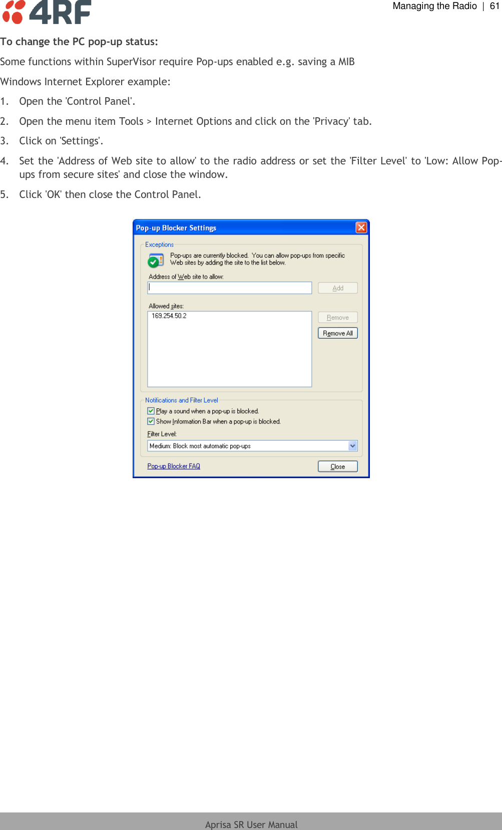
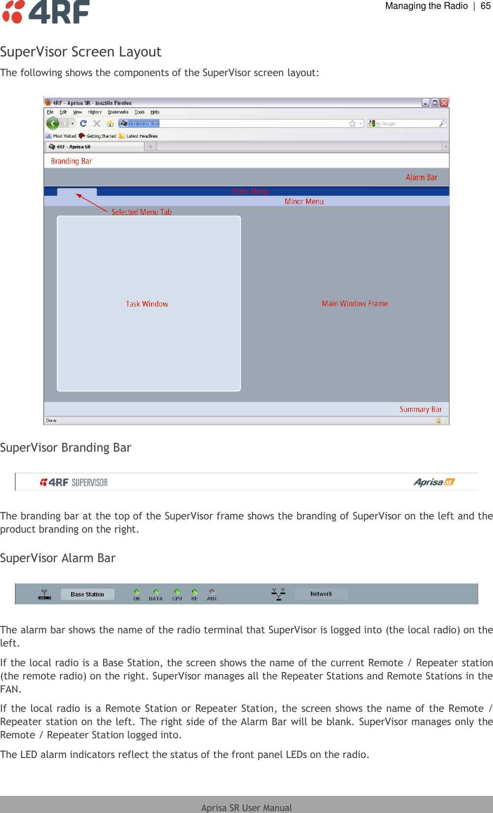
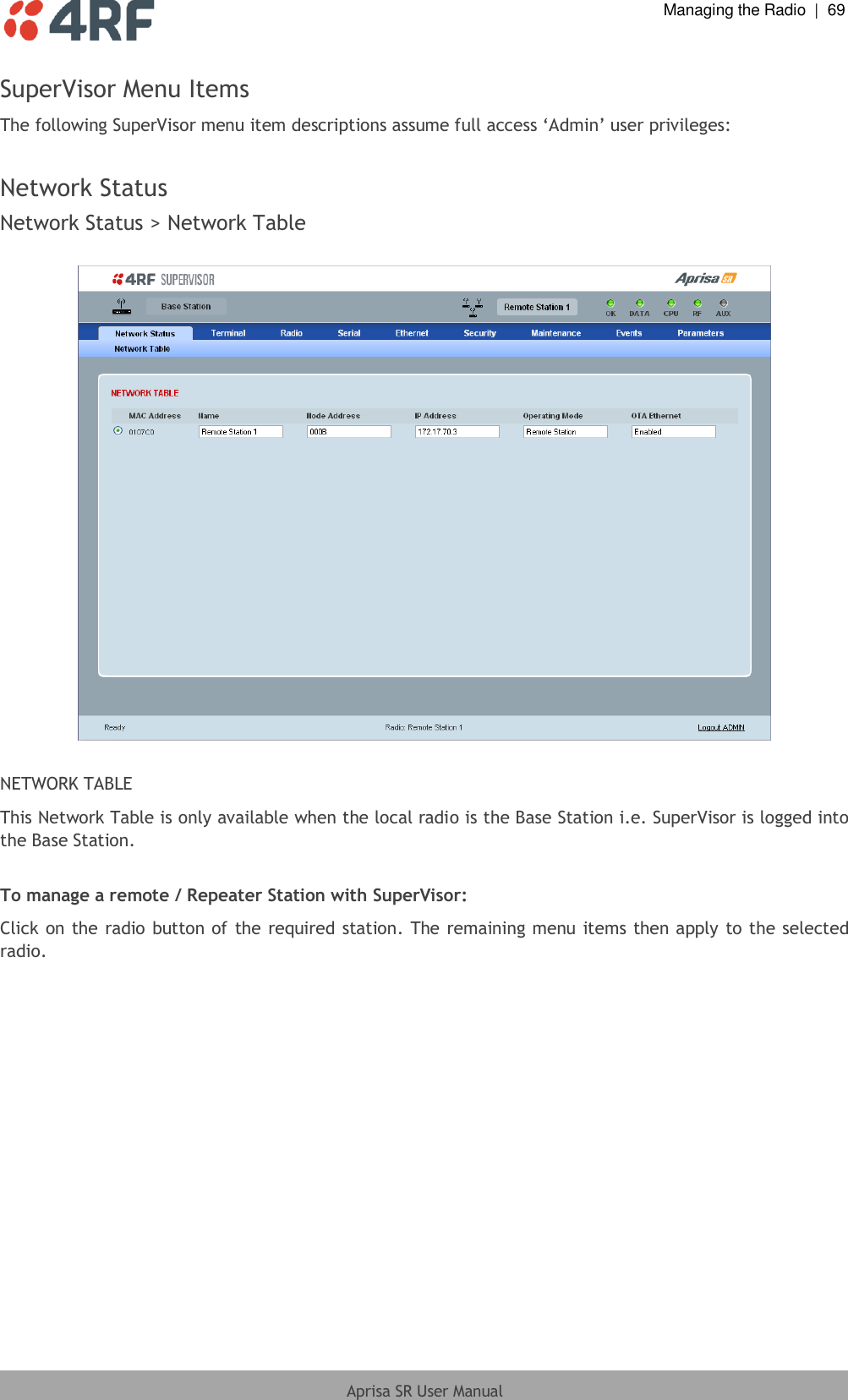
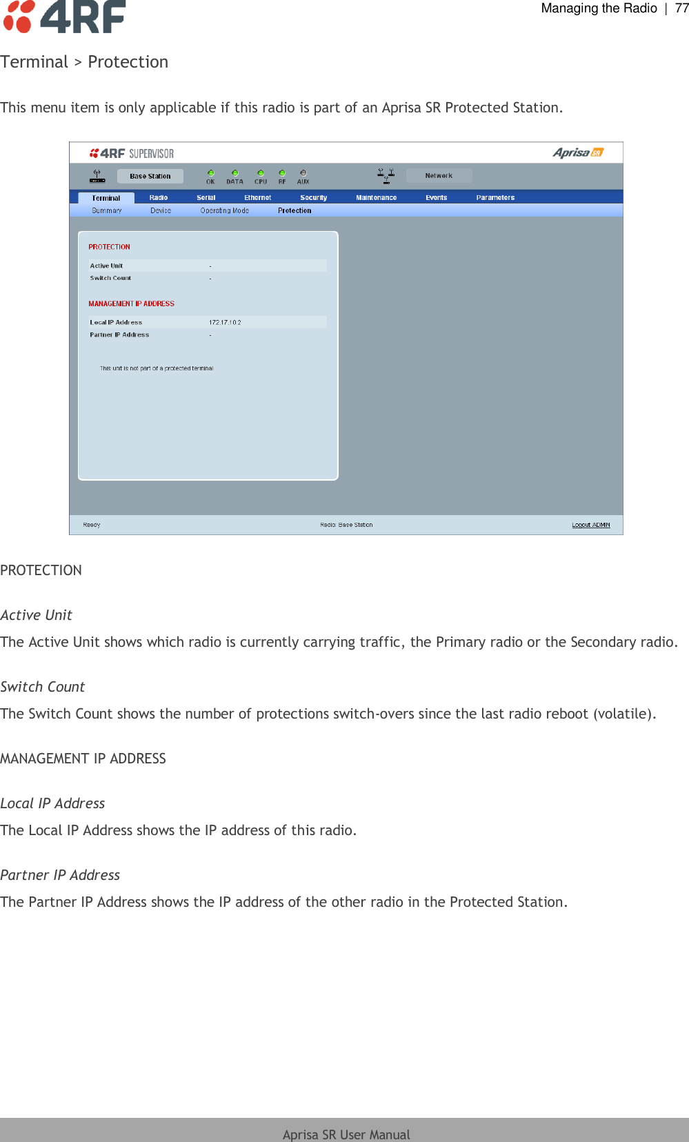
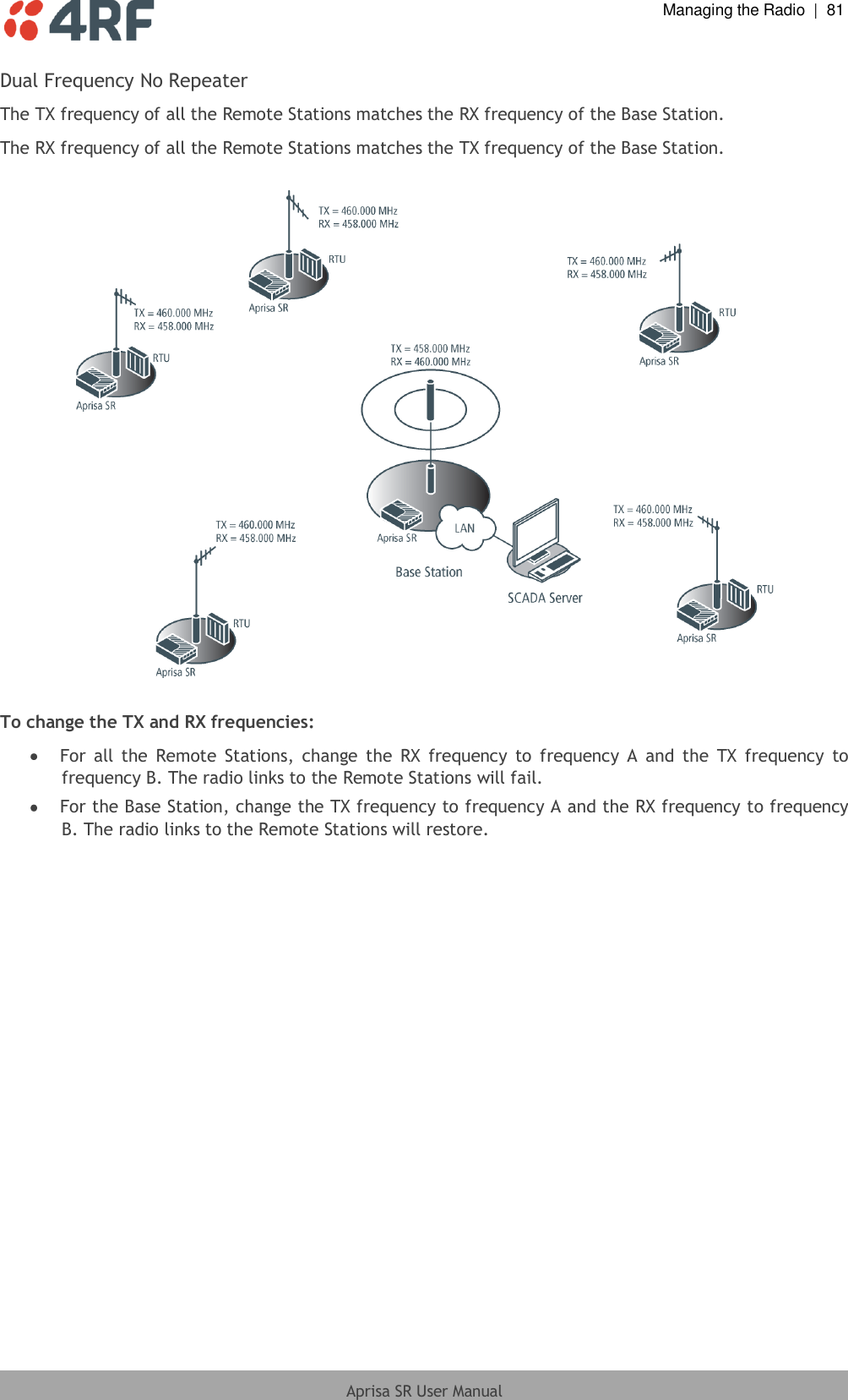
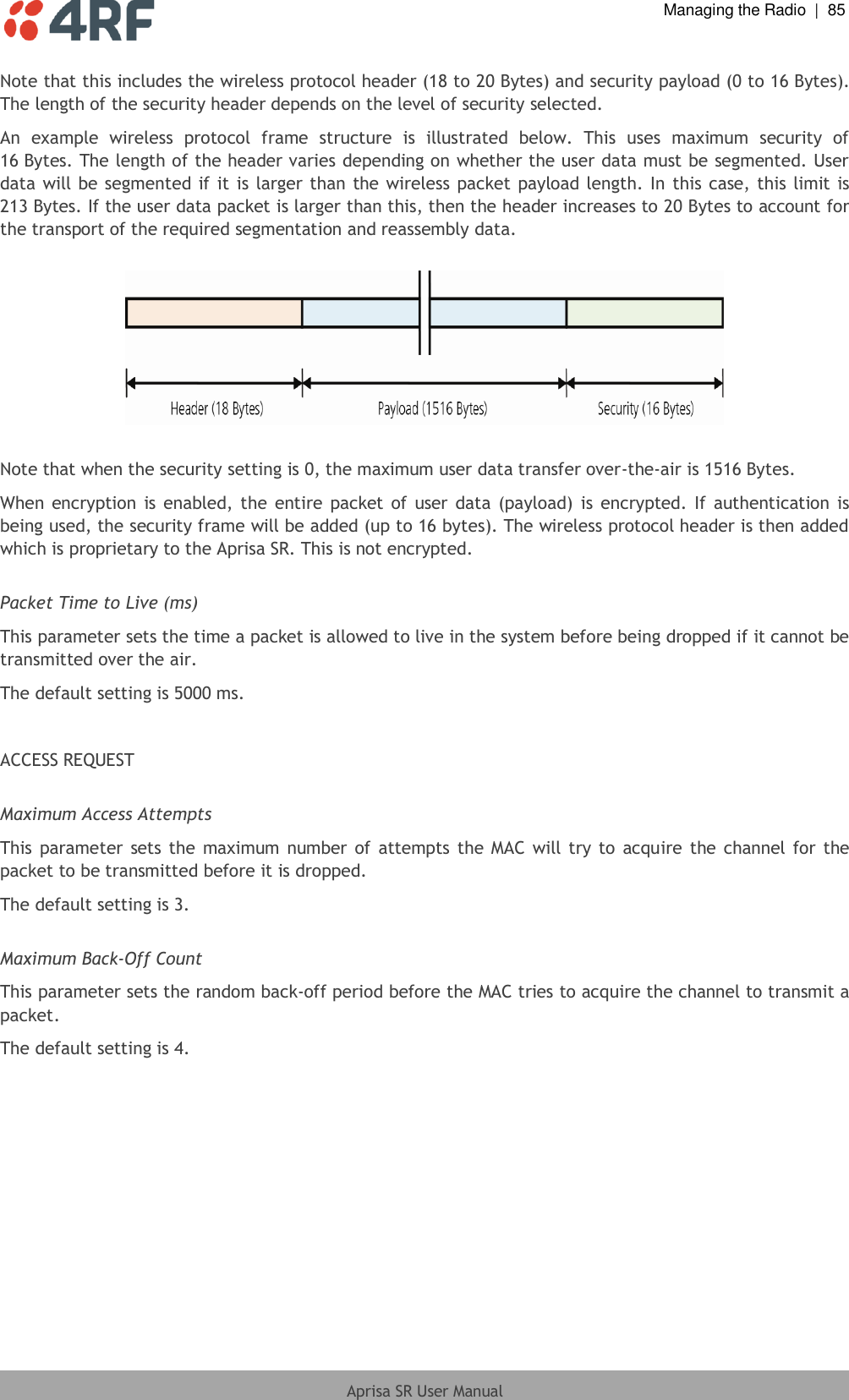
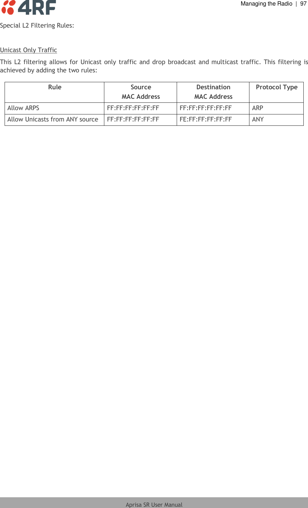
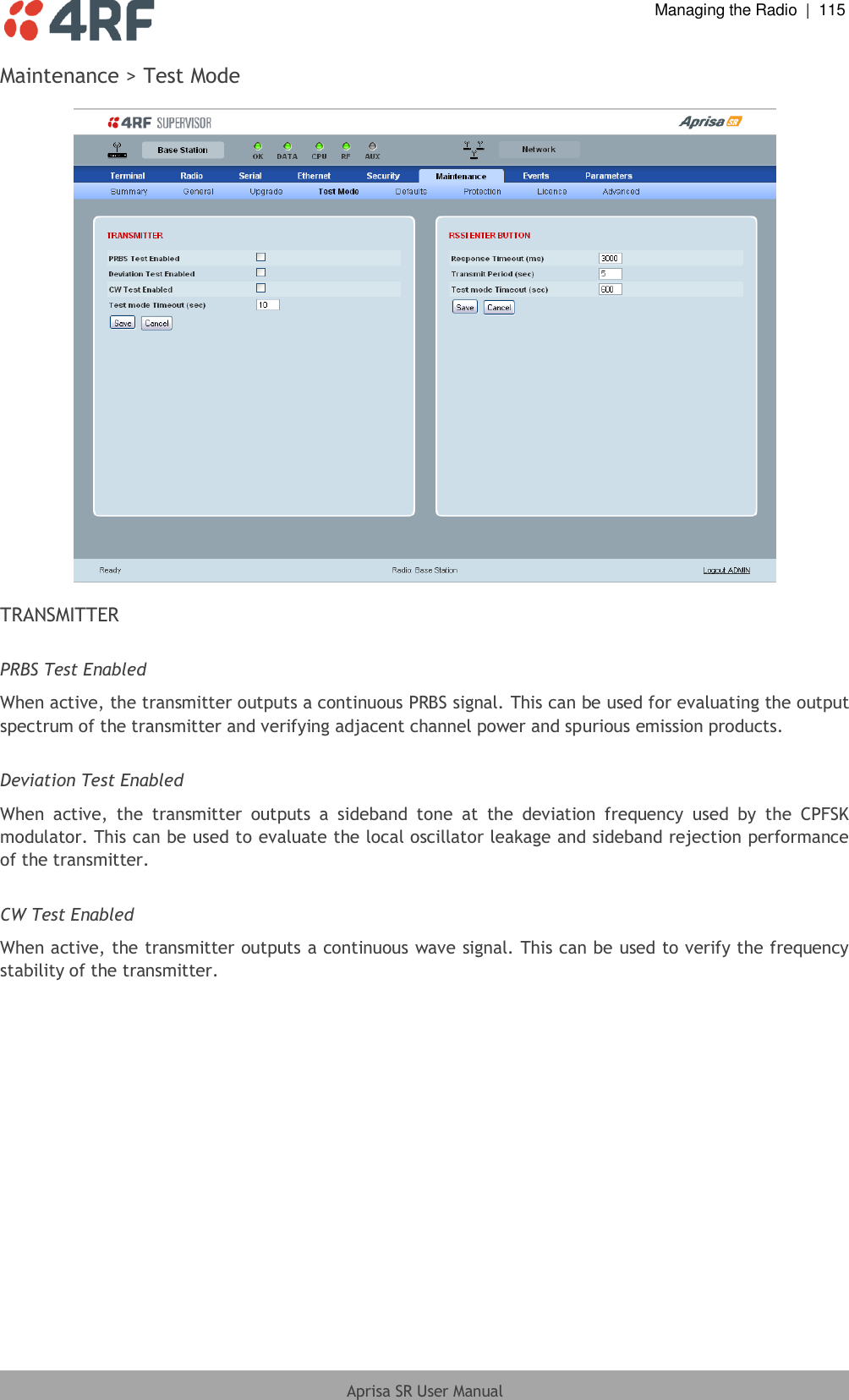
![Managing the Radio | 105 Aprisa SR User Manual Encryption Password This parameter sets the Encryption password. This is used to create the AES encryption key. Good password policy: contains at least eight characters, and contains at least one upper case letter, and contains at least one lower case letter, and contains at least one digit or another character such as !@#$%^&(){}[]<>... , and is not a term in a familiar language or jargon, and is not identical to or derived from the accompanying account name, from personal characteristics or from information from one’s family/social circle, and is easy to remember, for instance by means of a key sentence, and can be typed in fluently. PROTOCOL SETTINGS Telnet option This parameter option determines if you can manage the radio via a Telnet session. The default setting is disabled. ICMP option (Internet Control Message Protocol) This parameter option determines whether the radio will respond to a ping. The default setting is enabled. HTTPS option This parameter option determines if you can manage the radio via a HTTPS session (via a Browser). The default setting is enabled. SNMP option This parameter option determines if you can manage the radio via SNMP. The default setting is SNMPv2c. SNMP Proxy Support This parameter option enables an SNMP proxy server in the Base Station. This proxy server reduces the radio link traffic during SNMP communication to Remote / Repeater Stations. This option applies to the Base Station only. The default setting is disabled. This option can also be used if the radio has Serial Only interfaces.](https://usermanual.wiki/4RF/SRN0400012A/User-Guide-1633555-Page-108.png)
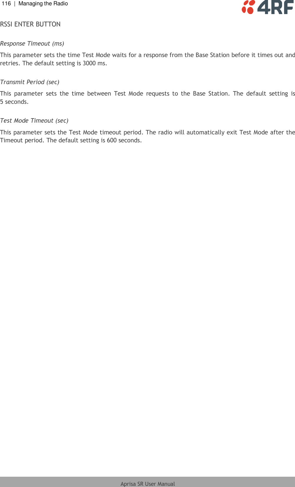
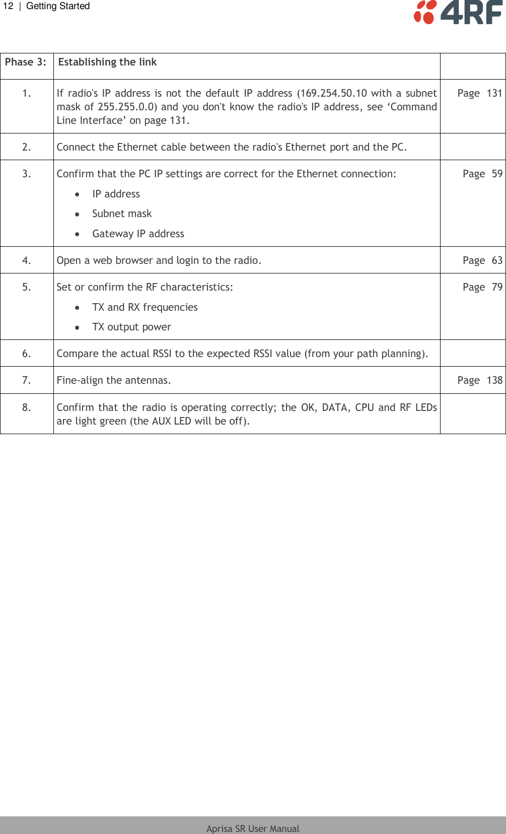
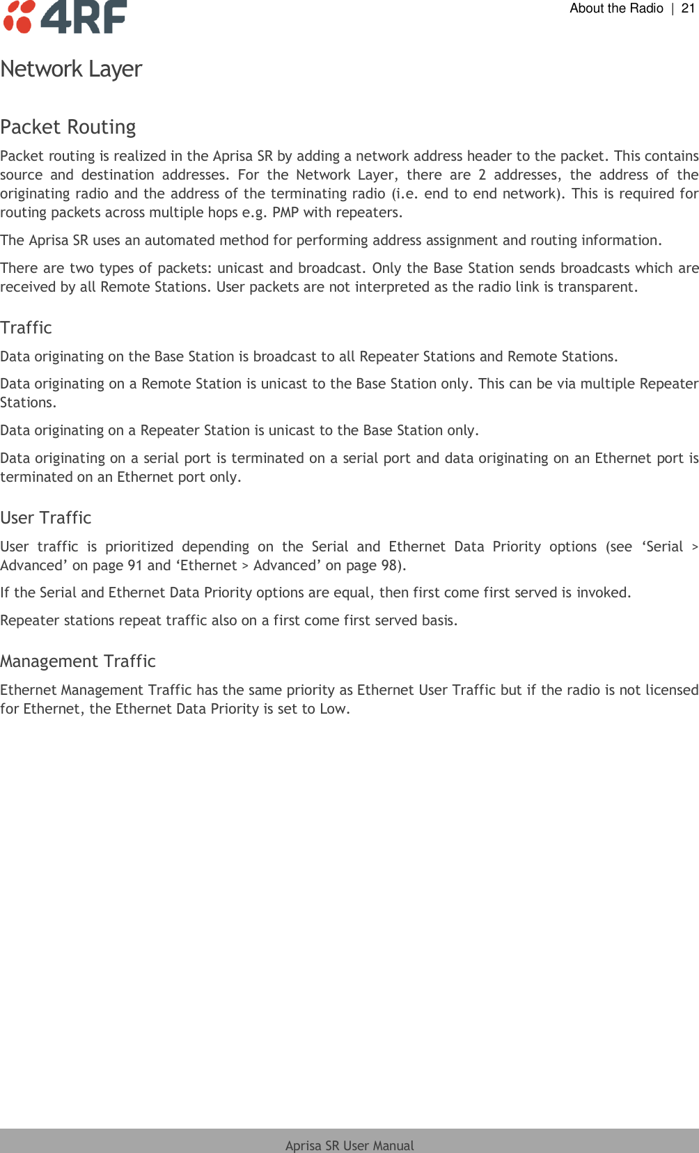
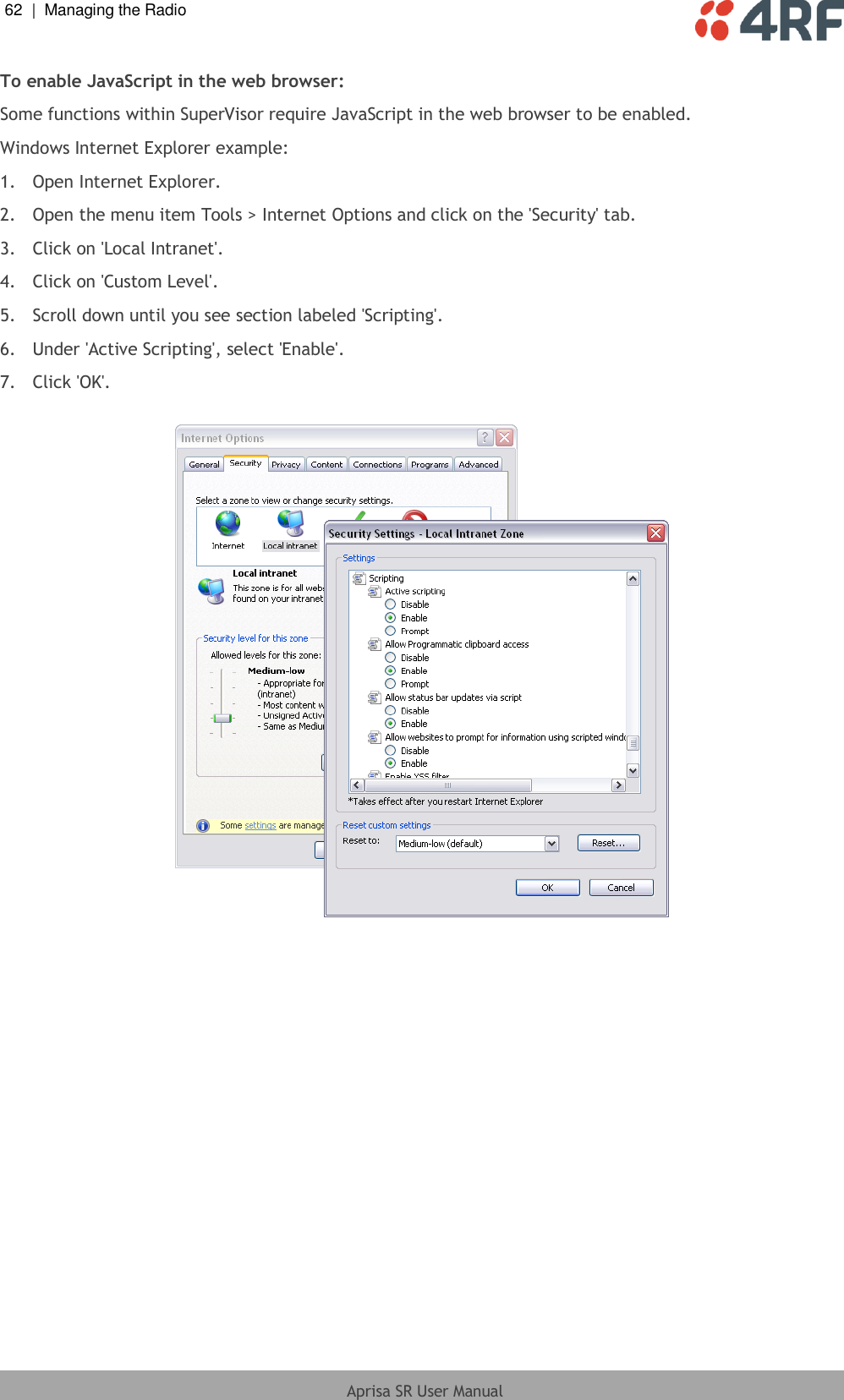
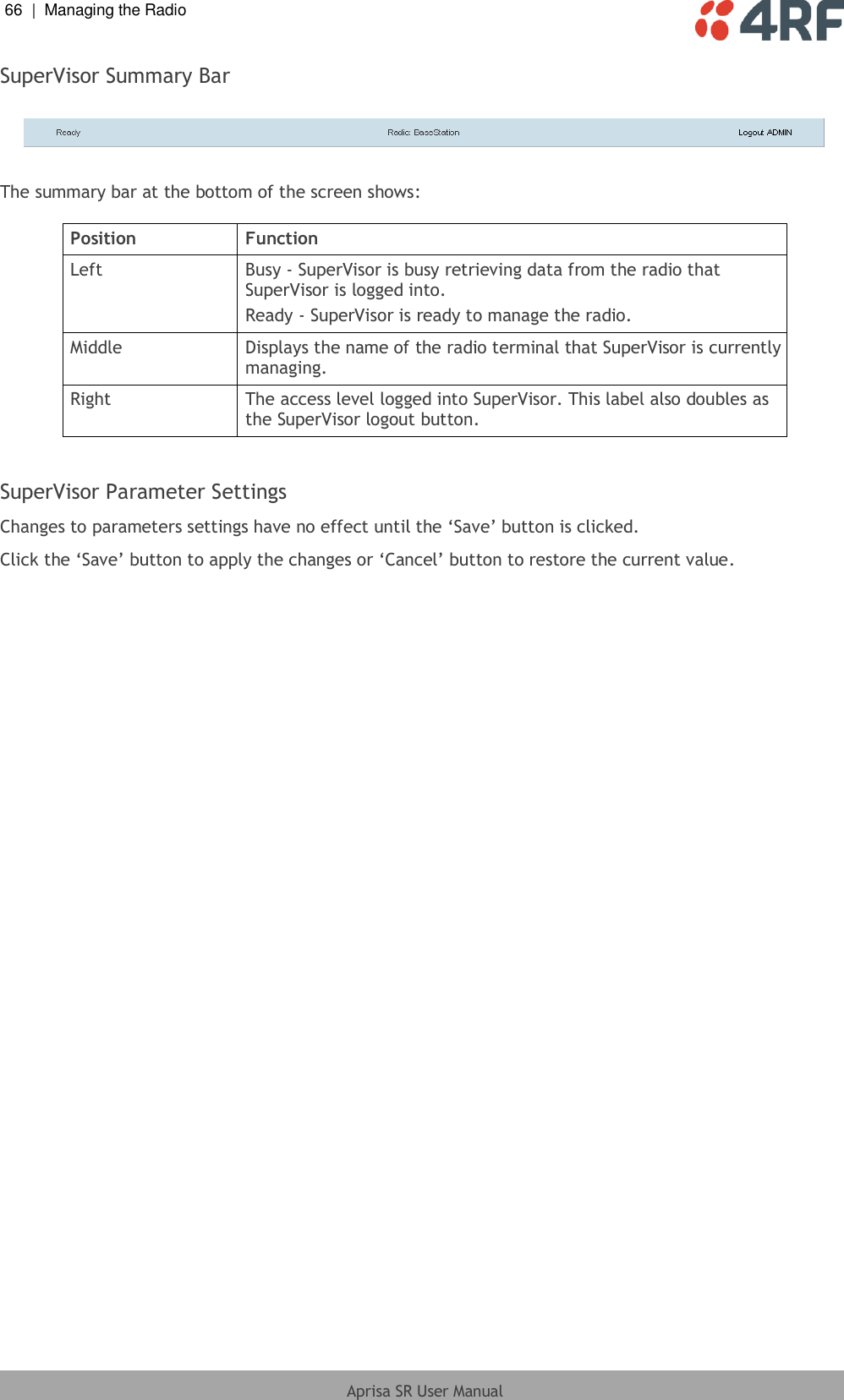
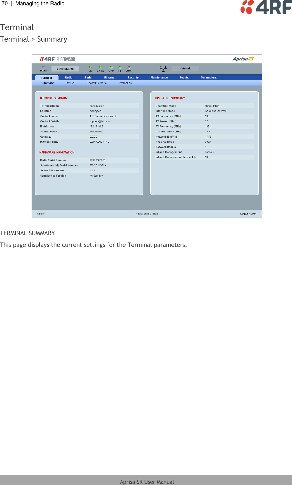
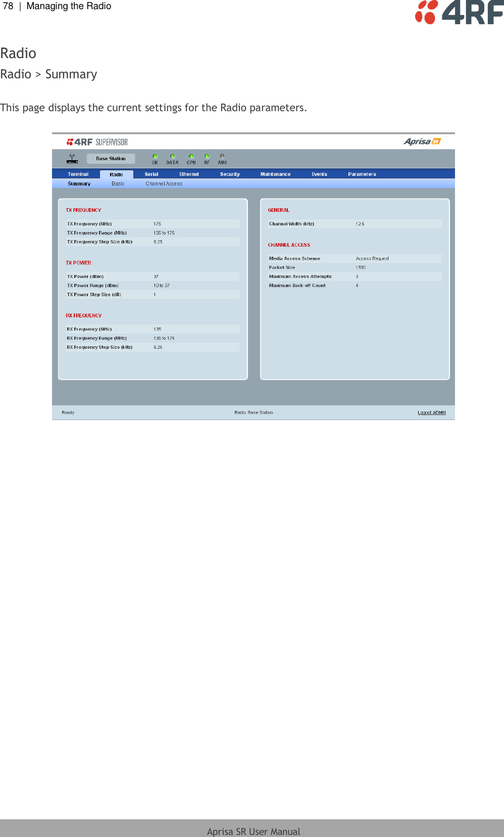
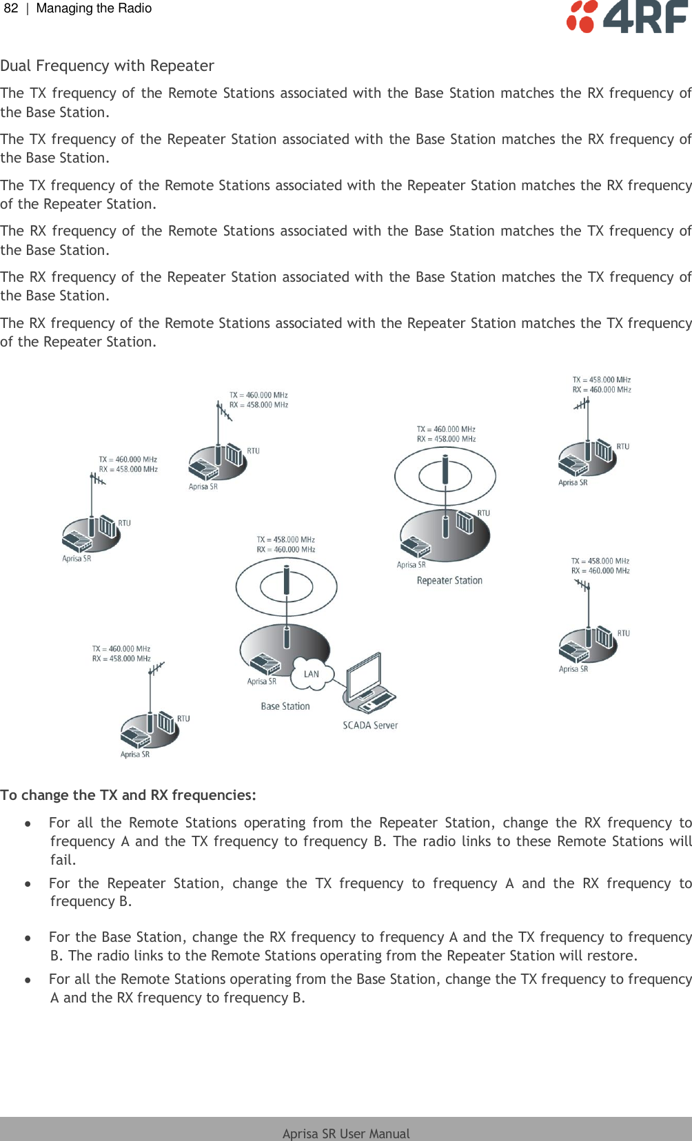
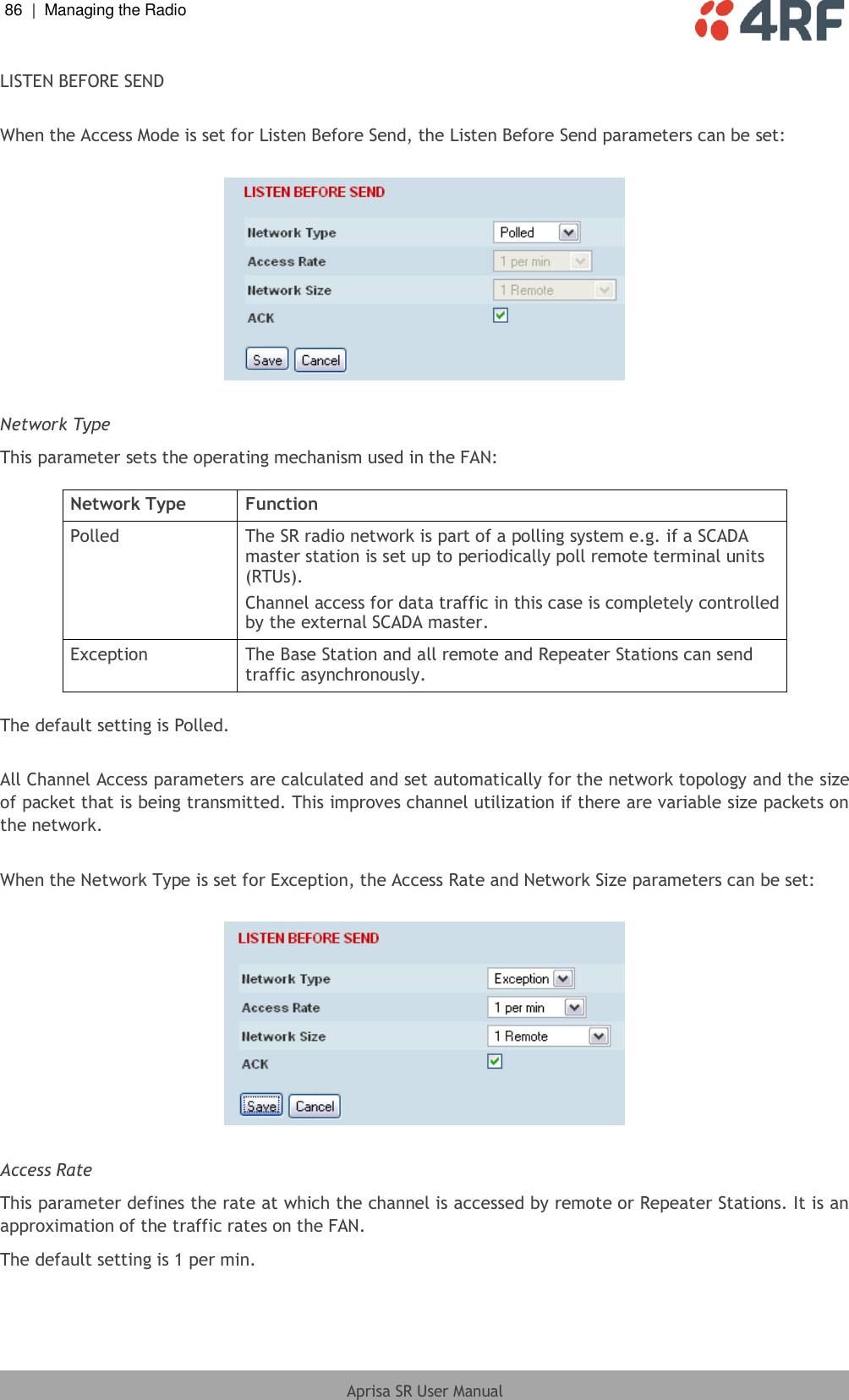
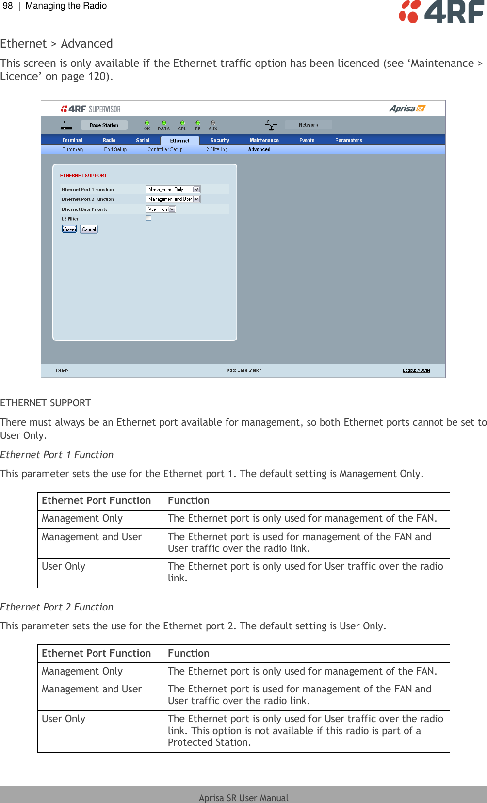
![134 | Managing the Radio Aprisa SR User Manual CLI Commands To enter a CLI command: 1. Type the first few characters of the command and hit Tab. This auto completes the command. 2. Enter the command string and enter. Note: The CLI commands are case sensitive. The top level CLI command list is displayed by typing a ? at the command prompt. The following is a list of the top level CLI commands and their usage: CLI Command Usage adduser adduser [-g <password aging>] [-a <account aging>] [-i <role>] <userName> <userPassword> browser browser <state(STR)> cd cd <changeMode(STR)> clear Clears the screen config config userdefault save restore factorydefault restore deleteuser deleteuser <userName> editpasswd editpasswd <oldpassword> <newpassword> edituser edituser [-p <password>] [-g <password aging>] [-a <account aging>] [-i]](https://usermanual.wiki/4RF/SRN0400012A/User-Guide-1633555-Page-137.png)
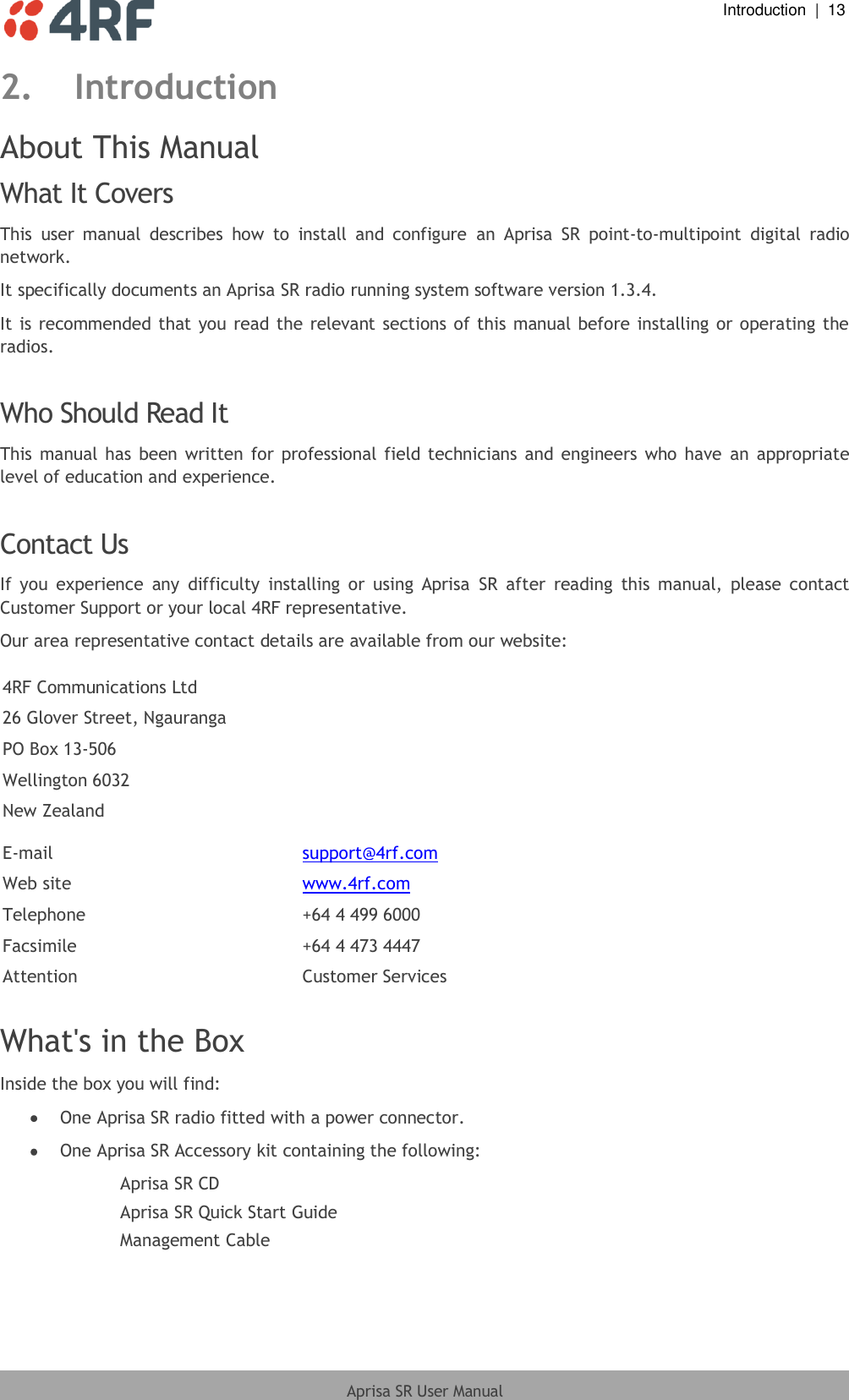
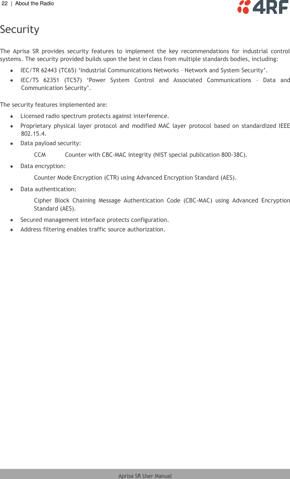
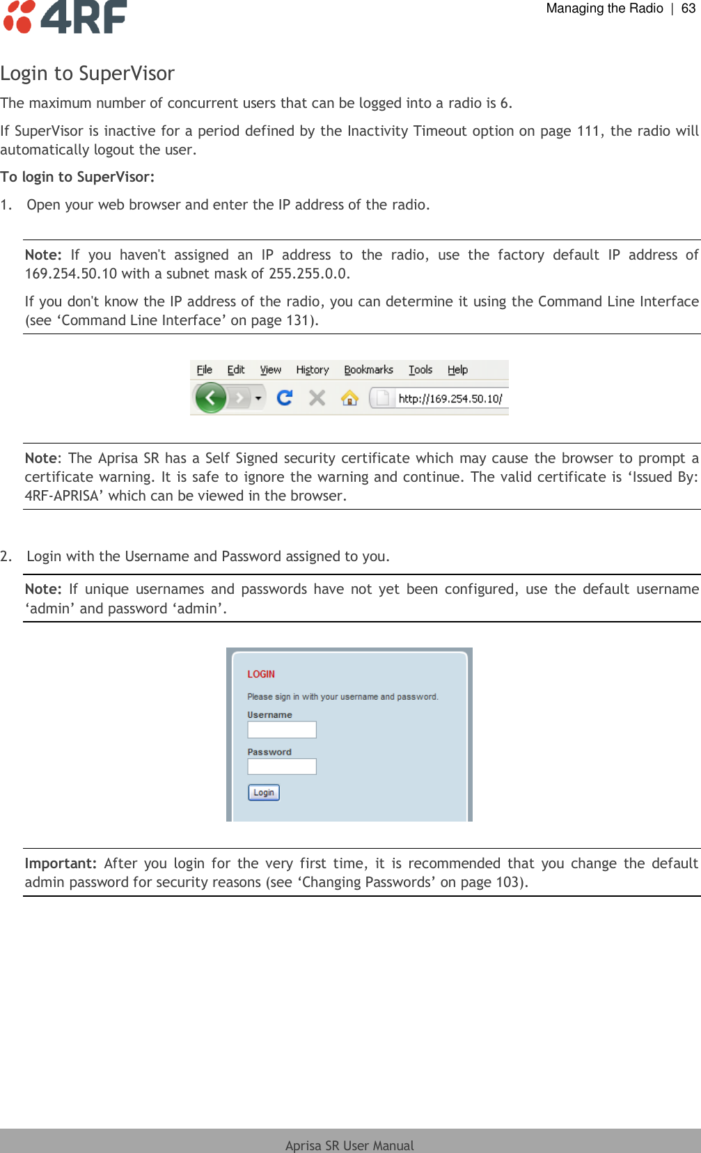
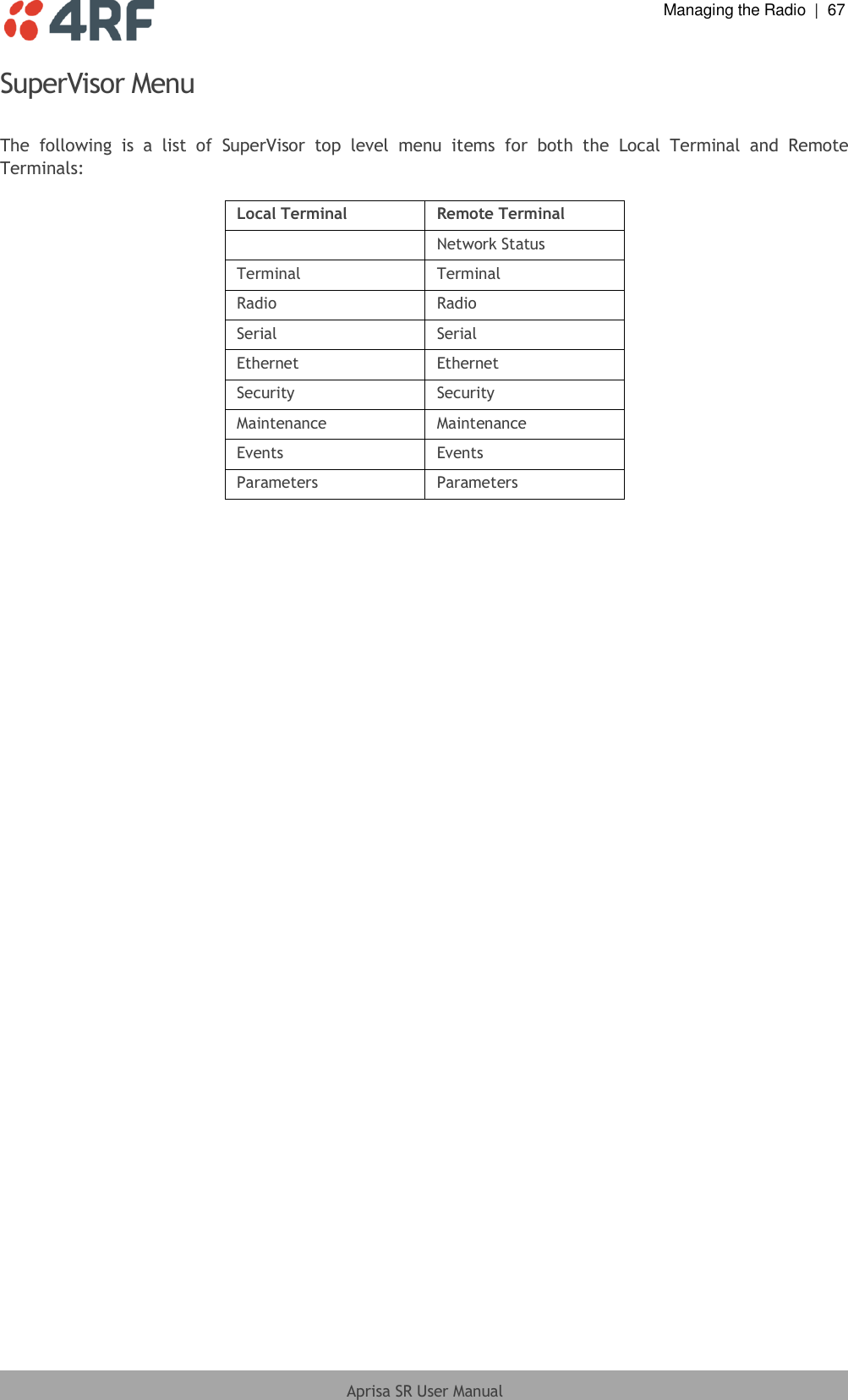
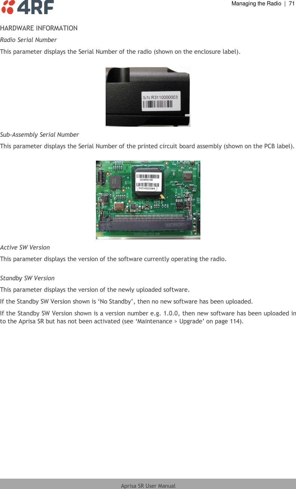
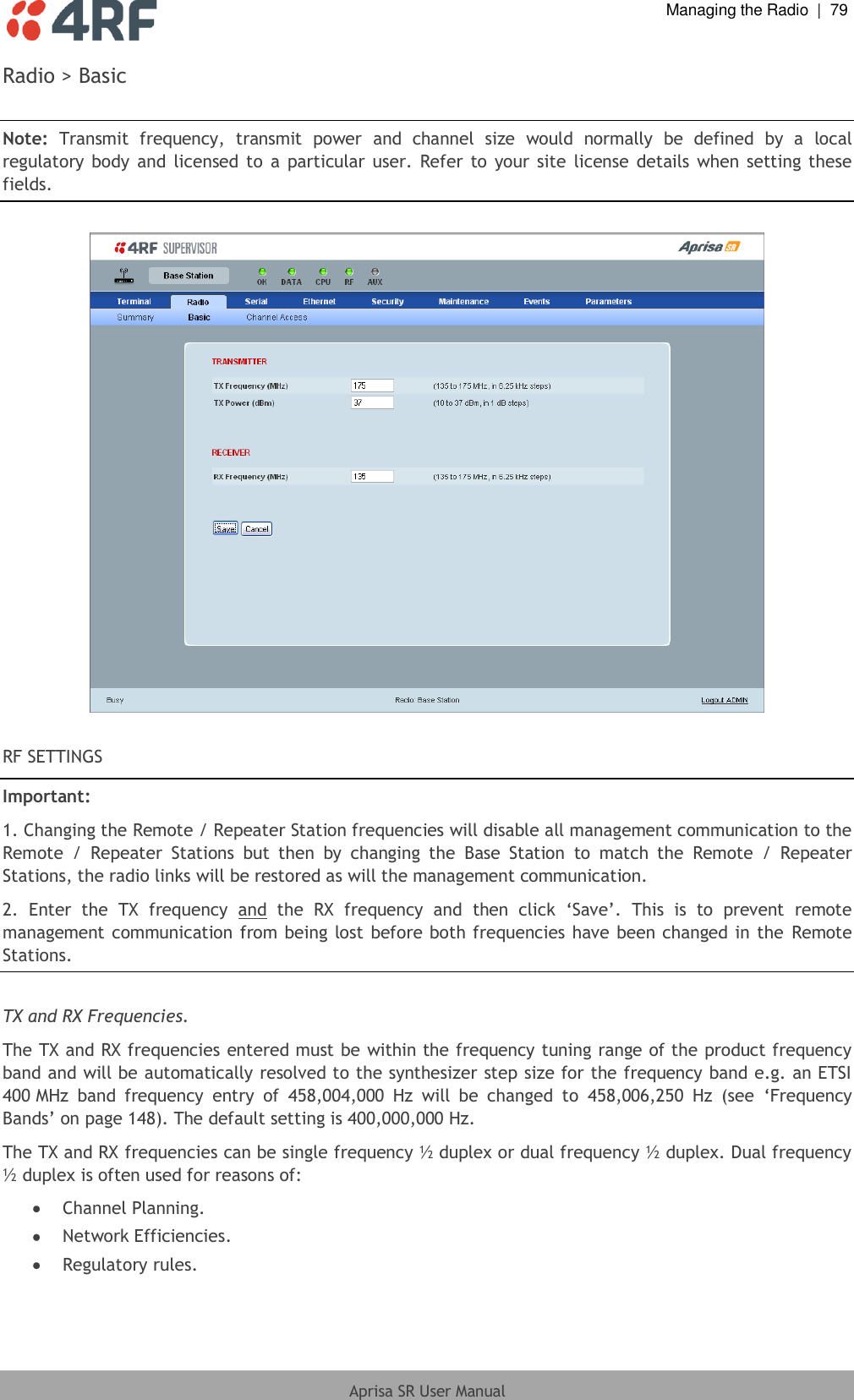
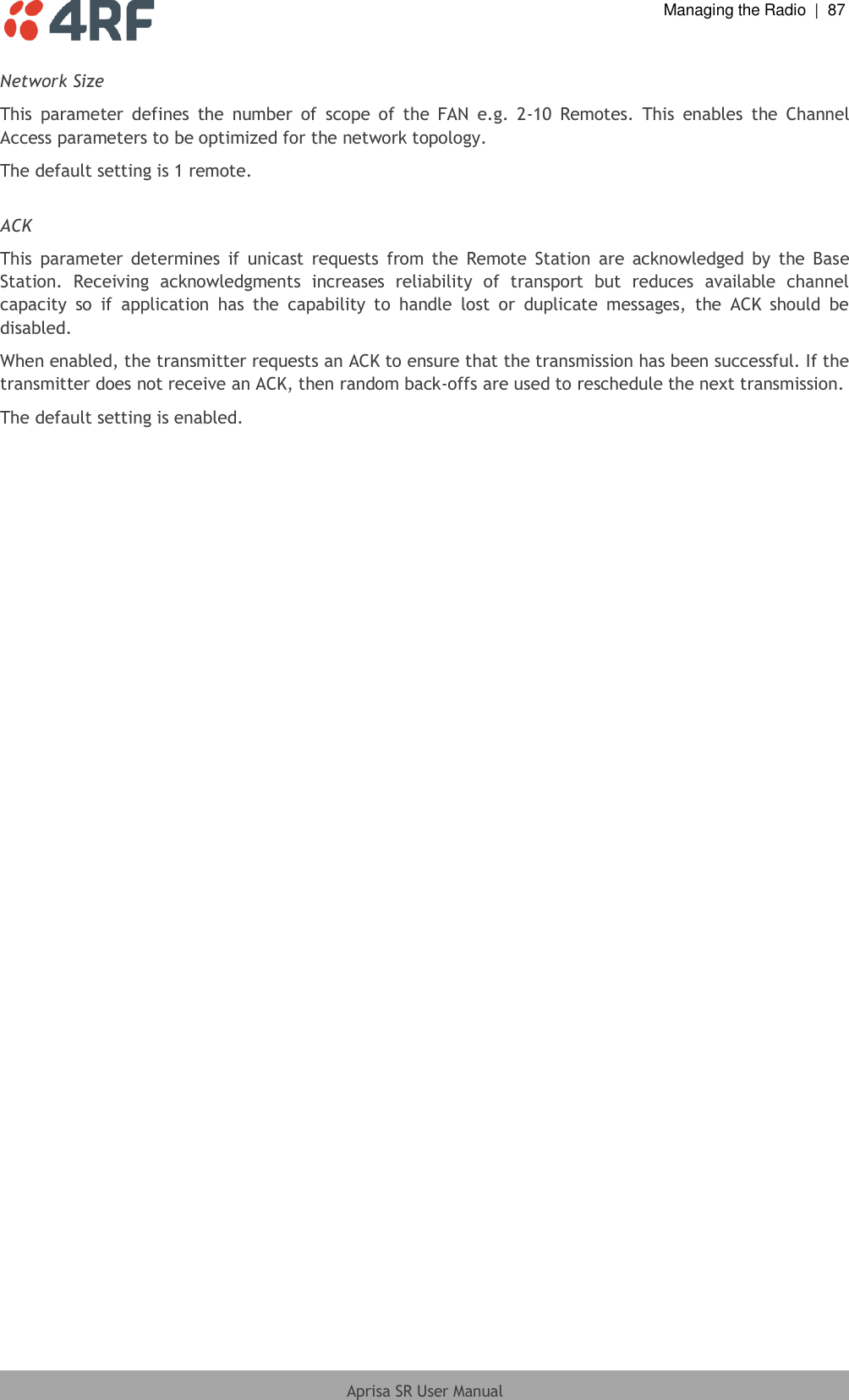
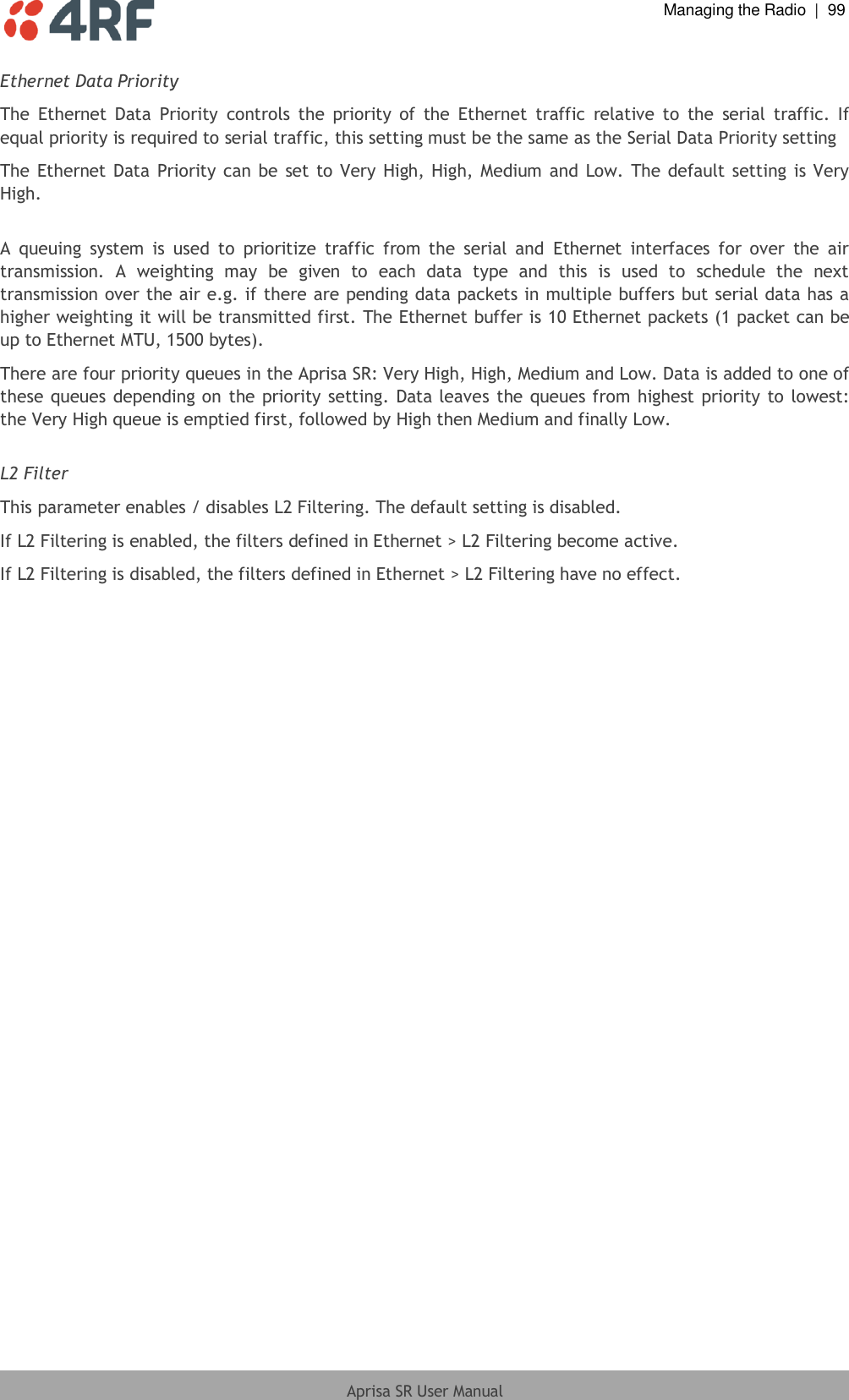
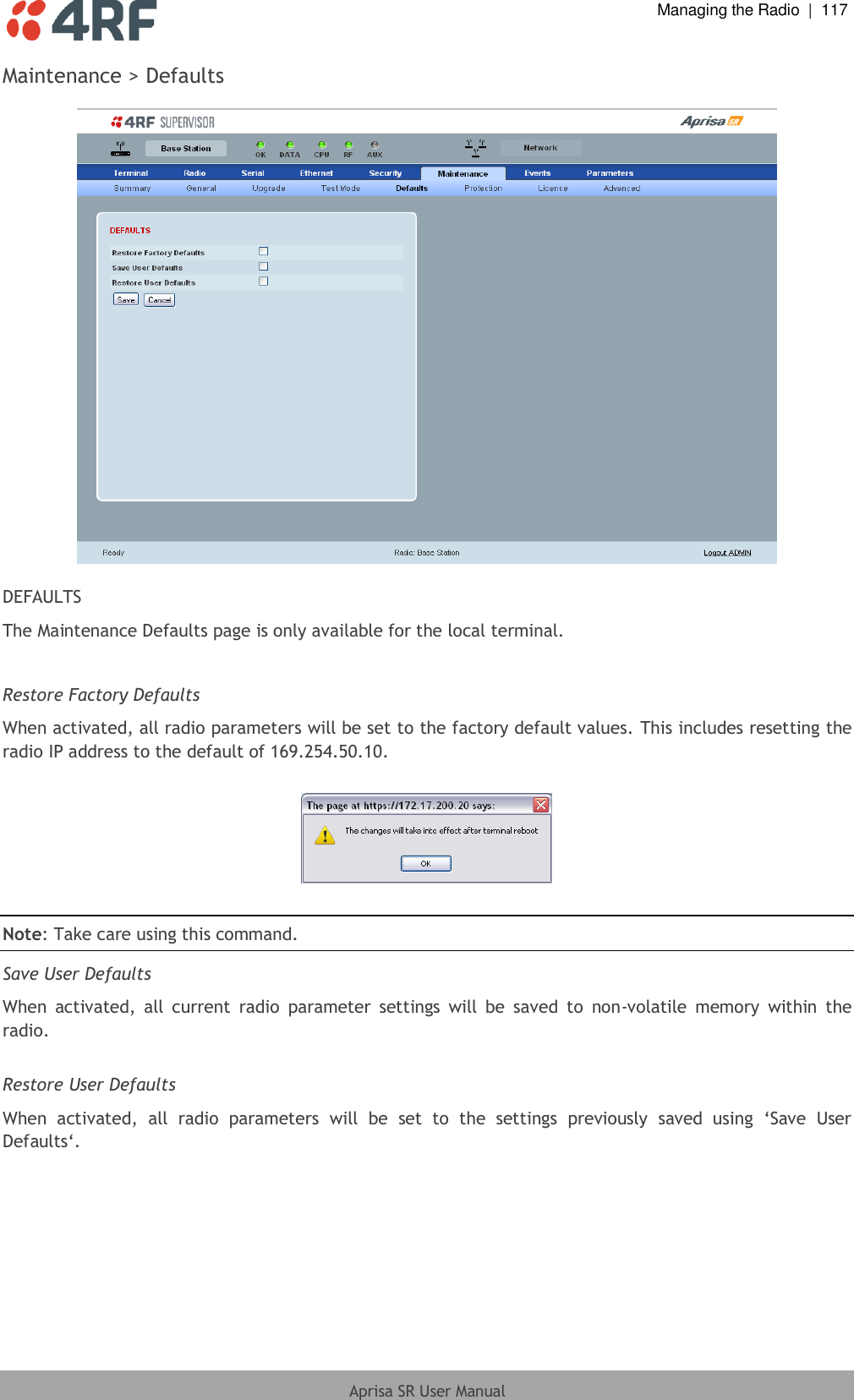
![Managing the Radio | 135 Aprisa SR User Manual get get [-m <mib name>] [-n <module name>] <attribute name> [indexes] list list <tablename> logout Logs out from the CLI ls Lists the settings for: (-) EthernetAdvanced (-) EthernetControllers (-) EthernetPorts (-) EthL2FilterTable (-) MaintenanceAdvanced (-) MaintenanceDefaults (-) MaintenanceGeneral (-) MaintenanceLicence (-) MaintenanceTestmode (-) MaintenanceUpgrade (+) NetworkTable (-) RadioChannelAccess (-) RadioRfSettings (-) SecuritySettings (+) SecurityUserTable (-) SerialAdvanced (-) SerialFlowControl (-) SerialPortSettings (-) TerminalDetails (-) TerminalOperatingMode reboot Reboots the radio set set [-m <mib name> ] [-n <module name>] <attribute name> <attribute set v] who Shows the users currently logged into the radio](https://usermanual.wiki/4RF/SRN0400012A/User-Guide-1633555-Page-138.png)