User Manual

November 2011
Version 1.3.4a

| 1
Aprisa SR User Manual
Copyright
Copyright © 2011 4RF Communications Ltd. All rights reserved.
This document is protected by copyright belonging to 4RF Communications Ltd and may not be reproduced
or republished in whole or part in any form without the prior written permission of 4RF Communications
Ltd.
Trademarks
Aprisa and the 4RF logo are trademarks of 4RF Communications Limited.
Windows is a registered trademark of Microsoft Corporation in the United States and other countries. Java
and all Java-related trademarks are trademarks or registered trademarks of Sun Microsystems, Inc. in the
United States and other countries. All other marks are the property of their respective owners.
Disclaimer
Although every precaution has been taken preparing this information, 4RF Communications Ltd assumes no
liability for errors and omissions, or any damages resulting from use of this information. This document or
the equipment may change, without notice, in the interests of improving the product.
RoHS and WEEE compliance
The Aprisa SR is fully compliant with the European Commission’s RoHS (Restriction of Certain Hazardous
Substances in Electrical and Electronic Equipment) and WEEE (Waste Electrical and Electronic Equipment)
environmental directives.
Restriction of hazardous substances (RoHS)
The RoHS Directive prohibits the sale in the European Union of electronic equipment containing these
hazardous substances: lead, cadmium, mercury, hexavalent chromium, polybrominated biphenyls (PBBs),
and polybrominated diphenyl ethers (PBDEs).
4RF Communications has worked with its component suppliers to ensure compliance with the RoHS
Directive which came into effect on the 1st July 2006.
End-of-life recycling programme (WEEE)
The WEEE Directive concerns the recovery, reuse, and recycling of electronic and electrical equipment.
Under the Directive, used equipment must be marked, collected separately, and disposed of properly.
4RF Communications has instigated a programme to manage the reuse, recycling, and recovery of waste in
an environmentally safe manner using processes that comply with the WEEE Directive (EU Waste Electrical
and Electronic Equipment 2002/96/EC).
4RF Communications invites questions from customers and partners on its environmental programmes and
compliance with the European Commission’s Directives (sales@4RF.com).
2 |
Aprisa SR User Manual
Compliance General
The Aprisa SR digital radio predominantly operates within frequency bands that require a site license be
issued by the radio regulatory authority with jurisdiction over the territory in which the equipment is
being operated.
It is the responsibility of the user, before operating the equipment, to ensure that where required the
appropriate license has been granted and all conditions attendant to that license have been met.
Changes or modifications not approved by the party responsible for compliance could void the user’s
authority to operate the equipment.
Equipment authorizations sought by 4RF Communications are based on the Aprisa SR radio equipment
being installed at a fixed location and operated in point-to-multipoint or point-to-point mode within the
environmental profile defined by EN 300 019, Class 3.4. Operation outside these criteria may invalidate
the authorizations and / or license conditions.
The term ‘Radio’ with reference to the Aprisa SR User Manual, is a generic term for one end station of a
point-to-multipoint Aprisa SR network and does not confer any rights to connect to any public network or
to operate the equipment within any territory.
Compliance ETSI
The Aprisa SR radio is designed to comply with the European Telecommunications Standards Institute
(ETSI) specifications as follows:
Radio performance
EN 300 113-2
EMC
EN 301 489 Parts 1 & 5
Environmental
EN 300 019, Class 3.4
Safety
EN 60950-1:2006
Frequency band
Channel size
Power input
Notified
body
136-174 MHz
12.5 kHz, 25 kHz
12 VDC
400-470 MHz
12.5 kHz, 25 kHz
12 VDC
| 3
Aprisa SR User Manual
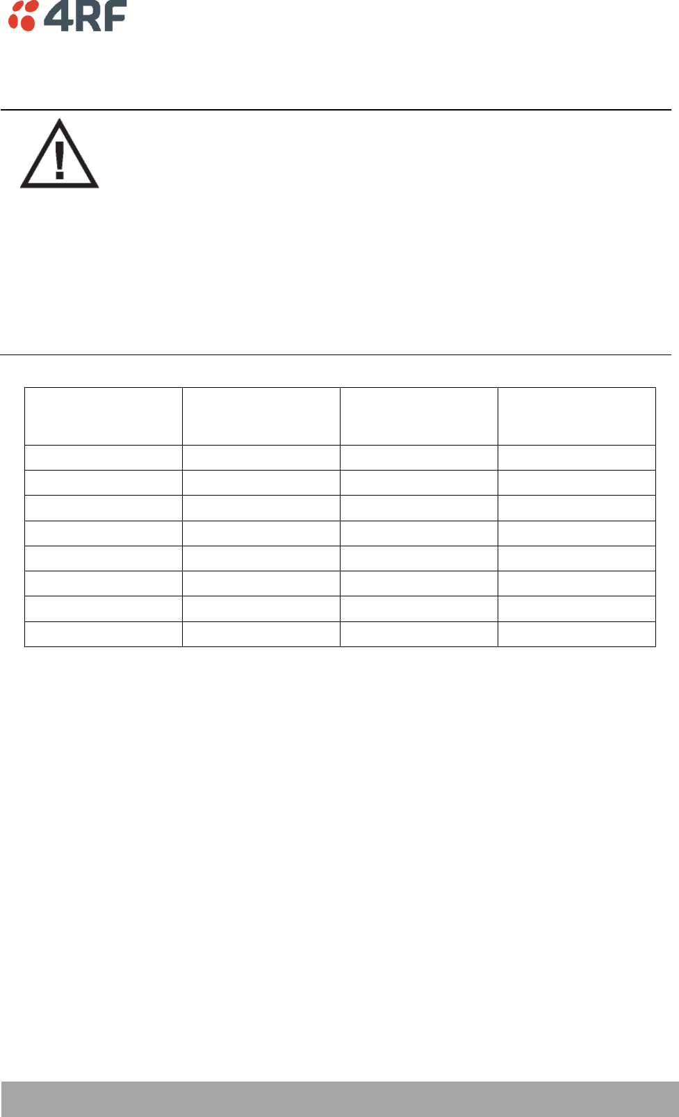
RF Exposure Warning
WARNING:
The installer and / or user of Aprisa SR radios shall ensure that a separation distance
as given in the following table is maintained between the main axis of the terminal’s
antenna and the body of the user or nearby persons.
Minimum separation distances given are based on the maximum values of the
following methodologies:
1. Maximum Permissible Exposure non-occupational limit (B or general public) of
47 CFR 1.1310 and the methodology of FCC’s OST/OET Bulletin number 65.
2. Reference levels as given in Annex III, European Directive on the limitation of
exposure of the general public to electromagnetic fields (0 Hz to 300 GHz)
(1999/519/EC). These distances will ensure indirect compliance with the
requirements of EN 50385:2002.
Frequency (MHz)
Maximum Power
(dBm)
Maximum Antenna
Gain (dBi)
Minimum Separation
Distance
(m)
136
+ 37
15
2.5
174
+ 37
15
2.5
330
+ 37
15
2.5
400
+ 37
15
2.5
470
+ 37
15
2.3
520
+ 37
15
2.2
850
+ 37
28
7.7
960
+ 37
28
7.2

Contents | 5
Aprisa SR User Manual
Contents
1. Getting Started .......................................................................... 11
2. Introduction .............................................................................. 13
About This Manual ............................................................................... 13
What It Covers ............................................................................ 13
Who Should Read It ...................................................................... 13
Contact Us ................................................................................. 13
What's in the Box ................................................................................ 13
Aprisa SR Accessory Kit .................................................................. 14
Aprisa SR CD Contents ................................................................... 14
Software ............................................................................ 14
Documentation .................................................................... 14
3. About the Radio ......................................................................... 15
The 4RF Aprisa SR Radio ........................................................................ 15
Product Overview ............................................................................... 16
Network Coverage and Capacity ....................................................... 16
Remote Messaging ........................................................................ 16
Repeater Messaging ...................................................................... 17
Product Features ................................................................................ 18
Functions .................................................................................. 18
Performance .............................................................................. 18
Usability ................................................................................... 18
Architecture ............................................................................... 19
Product Operation ................................................................. 19
Physical Layer ............................................................................. 19
Data Link Layer / MAC layer ............................................................ 19
Channel access ..................................................................... 19
Hop by Hop Transmission ......................................................... 20
Network Layer ............................................................................ 21
Packet Routing ..................................................................... 21
Security ........................................................................................... 22
Interfaces ......................................................................................... 23
Antenna Interface ........................................................................ 23
Ethernet Interface ....................................................................... 23
USB Interfaces ............................................................................ 23
RS-232 Interface .......................................................................... 23
Front Panel Connections ....................................................................... 24
LED Display Panel ............................................................................... 25
Normal Operation ........................................................................ 25
Software Upgrade ........................................................................ 25
Test Mode ................................................................................. 26

6 | Contents
Aprisa SR User Manual
4. Product Options ......................................................................... 27
Dual Antenna Port ............................................................................... 27
Protected Station ............................................................................... 28
Operation .................................................................................. 28
Configuration Management ...................................................... 29
Switch Over ............................................................................... 29
Switching Criteria ................................................................. 29
Hardware Manual Lock............................................................ 30
Remote Control .................................................................... 30
Installation ................................................................................ 31
Mounting ............................................................................ 31
Cabling .............................................................................. 31
Power ............................................................................... 31
Maintenance .............................................................................. 32
Changing the Protected Station IP Addresses ................................. 32
Protected Station Software Upgrade ........................................... 32
Replacing a Protected Station Faulty Radio ................................... 33
Setting the Software Manual Lock .............................................. 33
Spares ...................................................................................... 34
Replacing a Faulty Protection Switch .......................................... 34
Data Driven Protected Station................................................................. 35
Operation .................................................................................. 35
Switch Over ........................................................................ 36
Configuration Management ...................................................... 36
Installation ................................................................................ 37
Mounting ............................................................................ 37
Cabling .............................................................................. 38
Power ............................................................................... 38
5. Implementing the Network ........................................................... 39
Network Topologies ............................................................................. 39
Point-To-Point Network .......................................................... 39
Point-to-Multipoint Network ..................................................... 39
Point-to-Multipoint with Repeater 1 ............................................ 39
Point-to-Multipoint with Repeater 2 ............................................ 39
Initial Network Deployment ................................................................... 40
Install the Base Station .................................................................. 40
Installing the Remote Stations ......................................................... 40
Install a Repeater Station ............................................................... 40
Network Changes ................................................................................ 41
Adding a Repeater Station .............................................................. 41
Adding a Remote Station ................................................................ 41

Contents | 7
Aprisa SR User Manual
6. Preparation............................................................................... 43
Bench Setup ...................................................................................... 43
Path Planning .................................................................................... 44
Antenna Selection and Siting ........................................................... 44
Base or Repeater Station ......................................................... 44
Remote Station .................................................................... 45
Antenna Siting ..................................................................... 46
Coaxial Feeder Cables ................................................................... 47
Linking System Plan ...................................................................... 47
Site Requirements ............................................................................... 48
Power Supply .............................................................................. 48
Equipment Cooling ....................................................................... 48
Earthing and Lightning Protection ..................................................... 49
Feeder Earthing .................................................................... 49
Radio Earthing ..................................................................... 49
7. Installing the Radio ..................................................................... 50
Mounting .......................................................................................... 50
Required Tools ............................................................................ 50
DIN Rail Mounting ........................................................................ 51
Rack Shelf Mounting ..................................................................... 52
Wall Mounting ............................................................................. 52
Installing the Antenna and Feeder Cable .................................................... 53
Connecting the Power Supply ................................................................. 54
External Power Supplies ................................................................. 54
Spare Fuses ................................................................................ 55
Additional Spare Fuses ............................................................ 56

8 | Contents
Aprisa SR User Manual
8. Managing the Radio ..................................................................... 57
SuperVisor ........................................................................................ 57
Connecting to SuperVisor ............................................................... 57
Management PC Connection ..................................................... 58
PC Settings for SuperVisor ....................................................... 59
Login to SuperVisor................................................................ 63
Logout of SuperVisor .............................................................. 64
SuperVisor Screen Layout ........................................................ 65
SuperVisor Menu .......................................................................... 67
SuperVisor Menu Access .......................................................... 68
SuperVisor Menu Items............................................................ 69
Network Status .................................................................... 69
Terminal ............................................................................ 70
Radio ................................................................................ 78
Ethernet ............................................................................ 92
Security ........................................................................... 100
Maintenance...................................................................... 108
Events ............................................................................. 124
Parameters ....................................................................... 130
Command Line Interface ..................................................................... 131
Connecting to the Management Port ................................................ 131
CLI Commands .......................................................................... 134
Viewing the CLI Terminal Summary ........................................... 136
Changing the Radio IP Address with the CLI ................................. 136
In-Service Commissioning .................................................................... 137
Before You Start ............................................................................... 137
What You Will Need .................................................................... 137
Antenna Alignment ............................................................................ 138
Aligning the Antennas ................................................................. 138
9. Maintenance ............................................................................ 139
Radio Software Upgrade ...................................................................... 140
Upgrade Process ........................................................................ 140
Software Downgrade ................................................................... 141
10. Interface Connections ................................................................ 142
RJ-45 Connector Pin Assignments ........................................................... 142
Ethernet Interface Connections ............................................................. 142
RS-232 Serial Interface Connections ........................................................ 143
Protection Switch Remote Control Connections .......................................... 143
11. Alarm Types and Sources ............................................................ 144
Alarm Types .................................................................................... 144
Alarm Events ............................................................................ 144
Informational Events ................................................................... 147

Contents | 9
Aprisa SR User Manual
12. Specifications ........................................................................... 148
RF Specifications .............................................................................. 148
ETSI Compliant .......................................................................... 148
Frequency Bands ................................................................ 148
Channel Sizes .................................................................... 148
Transmitter ....................................................................... 149
Receiver .......................................................................... 149
Modem ............................................................................ 150
Data Payload Security .......................................................... 150
Interface Specifications ...................................................................... 151
Ethernet Interface ..................................................................... 151
RS-232 Asynchronous Interface ....................................................... 152
Protection Switch Specifications ............................................................ 152
Power Specifications .......................................................................... 153
Power Supply ............................................................................ 153
Power Consumption .................................................................... 153
Power Dissipation ...................................................................... 154
General Specifications ........................................................................ 155
Environmental .......................................................................... 155
Mechanical .............................................................................. 155
ETSI compliance ........................................................................ 155
13. Product End Of Life ................................................................... 156
End-of-Life Recycling Programme (WEEE) ................................................. 156
The WEEE Symbol Explained .......................................................... 156
WEEE Must Be Collected Separately ................................................. 156
YOUR ROLE in the Recovery of WEEE ................................................ 156
EEE Waste Impacts the Environment and Health .................................. 156
14. Abbreviations ........................................................................... 157
15. Index ...................................................................................... 158
Getting Started | 11
Aprisa SR User Manual
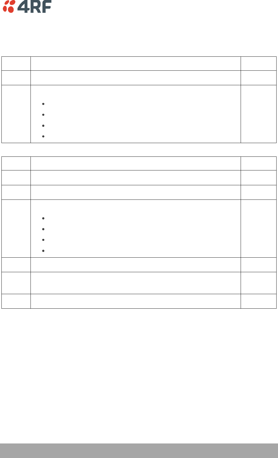
1. Getting Started
This section is an overview of the steps required to commission an Aprisa SR radio network in the field:
Phase 1:
Pre-installation
1.
Confirm path planning.
Page 44
2.
Ensure that the site preparation is complete:
Power requirements.
Tower requirements.
Environmental considerations, for example, temperature control.
Mounting space.
Page 47
Phase 2:
Installing the radios
1.
Mount the radio.
Page 50
2.
Connect earthing to the radio.
Page 49
3.
Confirm that the:
Antenna is mounted and visually aligned.
Feeder cable is connected to the antenna.
Feeder connections are tightened to recommended level.
Tower earthing is complete.
4.
Install lightning protection.
Page 49
5.
Connect the coaxial jumper cable between the lightning protection and the
radio antenna port.
Page 53
6.
Connect the power to the radio.
Page 54
12 | Getting Started
Aprisa SR User Manual
Phase 3:
Establishing the link
1.
If radio's IP address is not the default IP address (169.254.50.10 with a subnet
mask of 255.255.0.0) and you don't know the radio's IP address, see ‘Command
Line Interface’ on page 131.
Page 131
2.
Connect the Ethernet cable between the radio's Ethernet port and the PC.
3.
Confirm that the PC IP settings are correct for the Ethernet connection:
IP address
Subnet mask
Gateway IP address
Page 59
4.
Open a web browser and login to the radio.
Page 63
5.
Set or confirm the RF characteristics:
TX and RX frequencies
TX output power
Page 79
6.
Compare the actual RSSI to the expected RSSI value (from your path planning).
7.
Fine-align the antennas.
Page 138
8.
Confirm that the radio is operating correctly; the OK, DATA, CPU and RF LEDs
are light green (the AUX LED will be off).

Introduction | 13
Aprisa SR User Manual
2. Introduction
About This Manual
What It Covers
This user manual describes how to install and configure an Aprisa SR point-to-multipoint digital radio
network.
It specifically documents an Aprisa SR radio running system software version 1.3.4.
It is recommended that you read the relevant sections of this manual before installing or operating the
radios.
Who Should Read It
This manual has been written for professional field technicians and engineers who have an appropriate
level of education and experience.
Contact Us
If you experience any difficulty installing or using Aprisa SR after reading this manual, please contact
Customer Support or your local 4RF representative.
Our area representative contact details are available from our website:
4RF Communications Ltd
26 Glover Street, Ngauranga
PO Box 13-506
Wellington 6032
New Zealand
E-mail
support@4rf.com
Web site
www.4rf.com
Telephone
+64 4 499 6000
Facsimile
+64 4 473 4447
Attention
Customer Services
What's in the Box
Inside the box you will find:
One Aprisa SR radio fitted with a power connector.
One Aprisa SR Accessory kit containing the following:
Aprisa SR CD
Aprisa SR Quick Start Guide
Management Cable
14 | Introduction
Aprisa SR User Manual
Aprisa SR Accessory Kit
The accessory kit contains the following items:
Aprisa SR Quick Start Guide
Aprisa SR CD
Management Cable
USB Cable USB A to USB micro B, 1m
Aprisa SR CD Contents
The Aprisa SR CD contains the following:
Software
The latest version of the radio software (see ‘Radio Software Upgrade’ on page 140).
USB Serial Driver.
Web browsers - Mozilla Firefox and Internet Explorer are included for your convenience.
Adobe™ Acrobat® Reader® which you need to view the PDF files on the Aprisa SR CD.
Documentation
User manual - an electronic (PDF) version for you to view online or print.
Product collateral - application overviews, product description, quick start guide, case studies,
software release notes and white papers.
About the Radio | 15
Aprisa SR User Manual
3. About the Radio
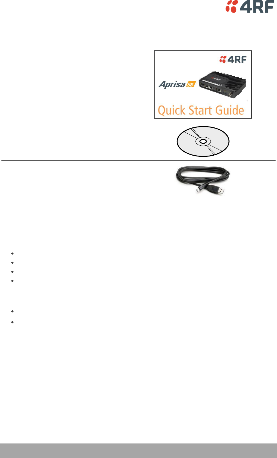
The 4RF Aprisa SR Radio
The 4RF Aprisa SR is a point-to-multipoint digital radio providing secure narrowband wireless data
connectivity for SCADA, infrastructure and telemetry applications.
The radios carry a combination of serial packet data and Ethernet data between the Base Station,
Repeater Stations and Remote Stations.
The Aprisa SR is configurable as a point-to-multipoint Base Station, a Remote Station or a Repeater
Station.

16 | About the Radio
Aprisa SR User Manual
Product Overview
Network Coverage and Capacity
In a simple point-to-multipoint network, an Aprisa SR, configured as a Base Station, will communicate with
multiple remote units in a given coverage area. With a link range of up to 60 km a typical deployment will
have 30 – 50 Remote Stations attached to the Base Station. However, geographic features, such as hills,
mountains, trees and foliage, or other path obstructions, such as buildings, tend to limit radio coverage.
Additionally, geography may reduce network capacity at the edge of the network where errors may occur
and require retransmission. However, the Aprisa SR uses Forward Error Correction (FEC) which greatly
improves the sensitivity performance of the radio resulting in less retries and minimal reduction in
capacity.
Ultimately, the overall performance of any specific network will be defined by a range of factors including
the geographic location, the number of Remote Stations in the Base Station coverage area and the traffic
profile across the network. Effective network design will distribute the total number of Remote Stations
across the available Base Stations to ensure optimal geographic coverage and network capacity.
Remote Messaging
Base Stations are fitted with omni-directional antennas and the Remote Stations use directional Yagi
antennas for higher gain. On start-up the Base Station transmits a registration message which is
recognized by the Remote Stations which respond with their own registration message. This allows the
Base Station to record the details of all the Remote Stations active in the network.
There are two message types in the Aprisa SR network, broadcast messages and unicast messages.
Broadcast messages are transmitted by the Base Station to the Remote Stations and unicast messages are
transmitted by the Remote Station to the Base Station.
All the Remote Stations, within the coverage area, will receive the messages broadcast from the Base
Station, but only the radio the message is intended for will action the message. Only the Base Station can
receive the unicast messages transmitted from the Remote Station. Unicast messages are ignored by other
Remote Stations which may be able to receive them. The Aprisa SR network is not designed for Remote
Stations to communicate with other Remote Stations.

About the Radio | 17
Aprisa SR User Manual
Repeater Messaging
The Aprisa SR uses a routed protocol throughout the network whereby messages contain source and
destination addresses. Upon registration, the radios populate an internal neighbor table to identify the
radios in the network. The Remote Stations will register with a Base Station, or a repeater, and the
repeater registers with a Base Station. In networks with a repeater, the repeater must register with the
Base Station before the remotes can register with the repeater.
Additionally, all messages contain a ‘message type’ field in the header and messages are designated as
either a ‘broadcast’ message, originating from a Base Station, or a ‘unicast’ message, originating from a
Remote Station.
In a network with a repeater, or multiple repeaters, the Base Station broadcasts a message which contains
a message type, a source address and a destination address. The repeater receives the message and
recognizes it is a broadcast message, from the message type and source address and re-broadcasts the
message across the network. All Remote Stations in the coverage area will receive the message but only
the radio with the destination address will act upon the message.
Similarly, the Remote Station will send a unicast message which contains a message type (unicast) a
source address and a destination address (the Base Station). The repeater will receive this message;
recognize the message type and source address and forward it to the destination address.
It is this methodology which prevents repeater-repeater loops. If there is repeater (A) which, in some
circumstances, is able to pick up the RF signal from another repeater (B), it will not forward the message
as it will only forward broadcast messages from the Base Station (recognized by the source address). For
unicast messages the repeater (A) will recognize that the message (from repeater (B)) is not from a
remote with which it has an association and similarly ignore the message.

18 | About the Radio
Aprisa SR User Manual
Product Features
Functions
Point-to-Point (PTP) or Point-to-Multipoint (PMP) operation half duplex.
Licensed frequency bands:
VHF 136-174 MHz
UHF 400-470 MHz
Channel sizes:
12.5 kHz
25 kHz
Typical deployment of 30 Remote Stations from one Base Station with a practical limit of a few
hundred Remote Stations.
Dual antenna port option for external duplexers or filters (half duplex operation)
Ethernet data interface plus RS-232 asynchronous data interface.
Data encryption and authentication.
Radio and user interface redundancy (provided with Aprisa SR Protected Station).
Complies with international standards, including ETSI RF, EMC, safety and environmental
standards.
Performance
Long distance operation.
High transmit power.
Low noise receiver.
Forward Error Correction.
Electronic tuning over the frequency band.
Thermal management for high power over a wide temperature range.
Usability
Configuration / diagnostics via front panel Management Port USB interface, Ethernet interface.
Remote station configuration / diagnostics over the radio link.
LED display for on-site diagnostics.
Firmware upgrade and diagnostic reporting via the Host Port USB flash drive.
Simple installation with integrated mounting holes for wall, DIN rail and rack shelf mounting.

About the Radio | 19
Aprisa SR User Manual
Architecture
Product Operation
There are three components to the wireless interface: the Physical Layer (PHY), the Data Link Layer (DLL)
and the Network Layer. These three layers are required to transport data across the wireless channel in
the Point-to-Multipoint (PMP) configuration. The Aprisa SR DLL is largely based on the 802.15.4 MAC layer
using a proprietary implementation.
Physical Layer
The Aprisa SR PHY uses a one or two frequency ½ duplex transmission mode which eliminates the need for
a duplexer. However, a Dual Antenna port option is available for separate transmit and receive antenna
connection to support external duplexers or filters (half duplex operation).
Remote nodes are predominantly in receive mode with only sporadic bursts of transmit data. This reduces
power consumption.
The Aprisa SR is a packet based radio. Data is sent over the wireless channel in discrete packets / frames,
separated in time. The PHY demodulates data within these packets with coherent detection.
The Aprisa SR PHY provides carrier, symbol and frame synchronisation predominantly through the use of
preambles. This preamble prefixes all packets sent over the wireless channel which enables fast
synchronisation.
Data Link Layer / MAC layer
The Aprisa SR PHY enables multiple users to be able to share a single wireless channel; however a DLL is
required to manage data transport. The two key components to the DLL are channel access and hop by
hop transmission.
Channel access
The Aprisa SR radio has two modes of channel access, Access Request and Listen Before Send.
Access Mode
Function
Access Request
Channel access scheme where the base stations controls the
communication on the channel. Remotes ask for access to the
channel, and the base station grants access if the channel is not
occupied.
Listen Before Send
Channel access scheme which consists of base station controlled
scheduling with remote station access using an access request /
access grant (AR/AG) scheme.

20 | About the Radio
Aprisa SR User Manual
Access Request
This scheme is particularly suited to digital SCADA systems where all data flows through the base station.
In this case it is important that the base station has contention-free access as it is involved in every
transaction. The channel access scheme assigns the base station as the channel access arbitrator and
therefore inherently it has contention-free access to the channel. This means that there is no possibility
of contention on data originating from the base station. As all data flows to or from the base station, this
significantly improves the robustness of the system.
All data messages are controlled via the AG (access grant) control message and therefore there is no
possibility of contention on the actual end user data. If a remote station accesses the channel, the only
contention risk is on the AR (access request) control message. These control messages are designed to be
as short as possible and therefore the risk of collision of these control messages is significantly reduced.
Should collisions occur these are resolved using a random back off and retry mechanism.
As the base station controls all data transactions multiple applications can be effectively handled,
including a mixture of polling and report by exception.
Listen Before Send
The Listen Before Send channel access scheme is realized using Carrier Sense Multiple Access (CSMA). In
this mode, a pending transmission requires the channel to be clear. This is determined by monitoring the
channel for other signals for a set time prior to transmission. This results in reduced collisions and
improved channel capacity.
There are still possibilities for collisions with this technique e.g. if two radios simultaneously determine
the channel is clear and transmit at the same time. In this case an acknowledged transaction may be used.
The transmitter requests an ACK to ensure that the transmission has been successful. If the transmitter
does not receive an ACK, then random backoffs are used to reschedule the next transmission.
There are a number of parameters that can be altered for the channel access such as back off times,
number of retries etc. To enable the most efficient use of the channel these parameters will differ for
each network (largely dependent on number of radios in the network).
Hop by Hop Transmission
Hop by Hop Transmission is realized in the Aprisa SR by adding a MAC address header to the packet. For
802.15.4, there are 2 addresses, the source and destination addresses.

About the Radio | 21
Aprisa SR User Manual
Network Layer
Packet Routing
Packet routing is realized in the Aprisa SR by adding a network address header to the packet. This contains
source and destination addresses. For the Network Layer, there are 2 addresses, the address of the
originating radio and the address of the terminating radio (i.e. end to end network). This is required for
routing packets across multiple hops e.g. PMP with repeaters.
The Aprisa SR uses an automated method for performing address assignment and routing information.
There are two types of packets: unicast and broadcast. Only the Base Station sends broadcasts which are
received by all Remote Stations. User packets are not interpreted as the radio link is transparent.
Traffic
Data originating on the Base Station is broadcast to all Repeater Stations and Remote Stations.
Data originating on a Remote Station is unicast to the Base Station only. This can be via multiple Repeater
Stations.
Data originating on a Repeater Station is unicast to the Base Station only.
Data originating on a serial port is terminated on a serial port and data originating on an Ethernet port is
terminated on an Ethernet port only.
User Traffic
User traffic is prioritized depending on the Serial and Ethernet Data Priority options (see ‘Serial >
Advanced’ on page 91 and ‘Ethernet > Advanced’ on page 98).
If the Serial and Ethernet Data Priority options are equal, then first come first served is invoked.
Repeater stations repeat traffic also on a first come first served basis.
Management Traffic
Ethernet Management Traffic has the same priority as Ethernet User Traffic but if the radio is not licensed
for Ethernet, the Ethernet Data Priority is set to Low.

22 | About the Radio
Aprisa SR User Manual
Security
The Aprisa SR provides security features to implement the key recommendations for industrial control
systems. The security provided builds upon the best in class from multiple standards bodies, including:
IEC/TR 62443 (TC65) ‘Industrial Communications Networks – Network and System Security’.
IEC/TS 62351 (TC57) ‘Power System Control and Associated Communications – Data and
Communication Security’.
The security features implemented are:
Licensed radio spectrum protects against interference.
Proprietary physical layer protocol and modified MAC layer protocol based on standardized IEEE
802.15.4.
Data payload security:
CCM Counter with CBC-MAC integrity (NIST special publication 800-38C).
Data encryption:
Counter Mode Encryption (CTR) using Advanced Encryption Standard (AES).
Data authentication:
Cipher Block Chaining Message Authentication Code (CBC-MAC) using Advanced Encryption
Standard (AES).
Secured management interface protects configuration.
Address filtering enables traffic source authorization.

About the Radio | 23
Aprisa SR User Manual
Interfaces
Antenna Interface
Single Antenna Option
1 x TNC, 50 ohm, female connector
Dual Antenna Port Option
2 x TNC, 50 ohm, female connectors
Ethernet Interface
2 x ports 10/100 base-T Ethernet layer 2 switch using RJ-45.
Used for Ethernet user traffic and product management.
USB Interfaces
1 x Management Port using USB micro type B connector.
Used for product configuration with the Command Line Interface (CLI).
1 x Host Port using USB standard type A connector.
Used for software upgrade and diagnostic reporting.
RS-232 Interface
1x RS-232 asynchronous port using RJ-45 connector.
Used for RS-232 async user traffic only.
24 | About the Radio
Aprisa SR User Manual
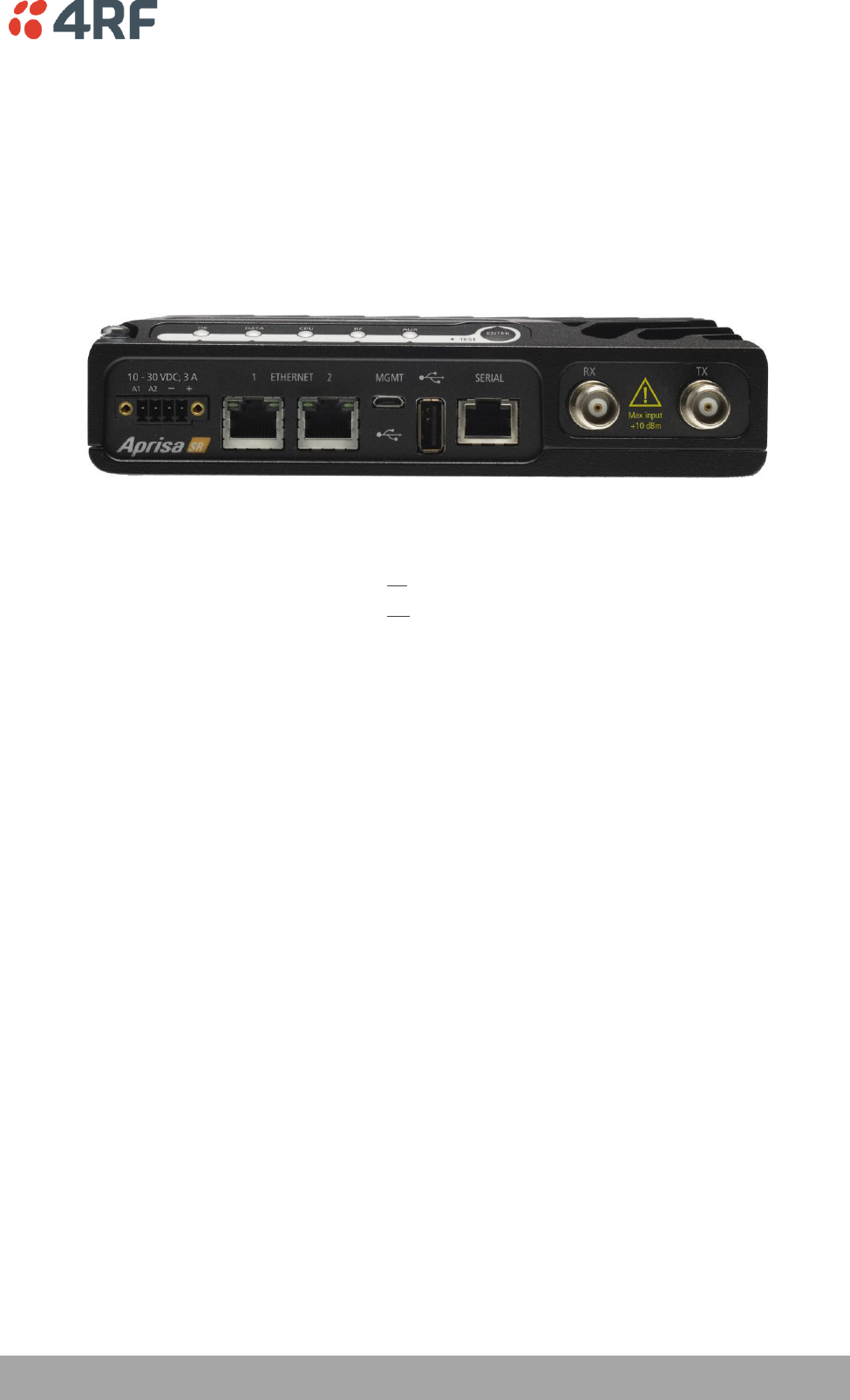
Front Panel Connections
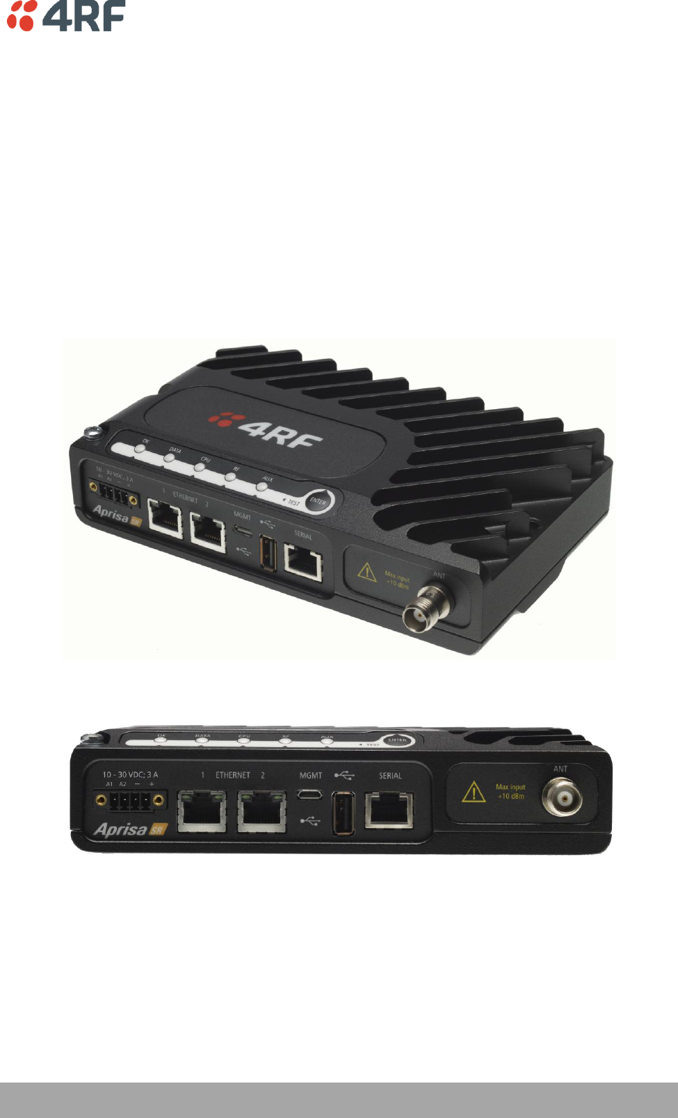
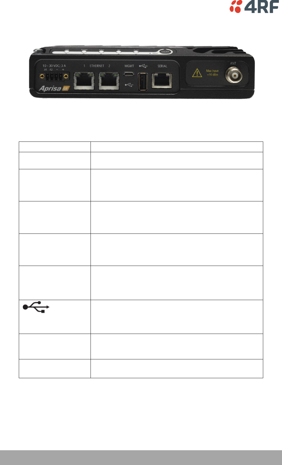
All connections to the radio are made on the front panel.
The functions of the connectors are (from left to right):
Designator
Description
A1 / A2
The A1, A2 are alarm connections are used in the Protected
Station.
10 - 30 VDC; 3A
+10 to +30 VDC (negative ground) DC power input using
Phoenix Contact 4 pin male screw fitting connector.
AC/DC and DC/DC power supplies are available as accessories
(see ‘External Power Supplies’ on page 54).
ETHERNET 1
Integrated 10Base-T/100Base-TX layer-2 Ethernet switch using
RJ-45 connector.
Used for Ethernet user traffic and product management (see
‘Ethernet > Port Setup’ on page 93).
ETHERNET 2
Integrated 10Base-T/100Base-TX layer-2 Ethernet switch using
RJ-45 connector.
Used for Ethernet user traffic and product management (see
‘Ethernet > Port Setup’ on page 93).
MGMT
Management Port using USB micro type B connector.
Used for product configuration with the Command Line
Interface.
(see ‘Connecting to the Management Port’ on page 131).
Host Port using USB standard type A connector.
Used for software upgrade and diagnostic reporting.
(see ‘Radio Software Upgrade’ on page 140 and ‘Maintenance >
General’ on page 111).
SERIAL
RS-232 traffic interface using a RJ-45 connector.
Used for RS-232 async user traffic only (see ‘Serial’ on page
88).
ANT
(Antenna connector)
TNC, 50 ohm, female connector for connection of antenna
feeder cable (see ‘Coaxial Feeder Cables’ on page 47).
About the Radio | 25
Aprisa SR User Manual
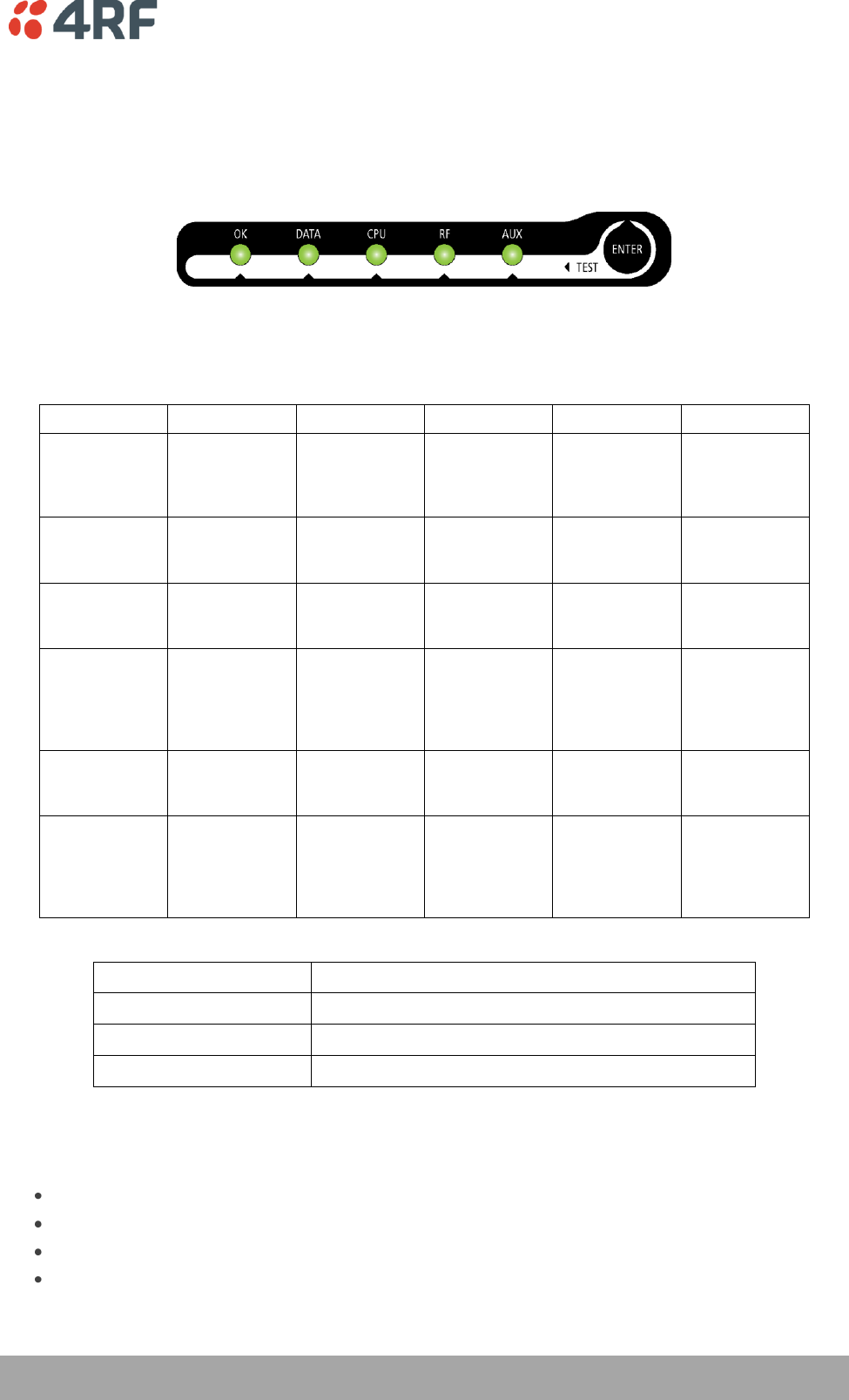
LED Display Panel
The Aprisa SR has an LED Display panel which provides on-site alarms / diagnostics without the need for
PC.
Normal Operation
In normal radio operation, the LEDs indicate the following conditions:
OK
DATA
CPU
RF
AUX
Solid
Red
Alarm present
with severity
Critical, Major
and Minor
RF path fail
Flashing
Red
Radio not
connected to a
Base Station
Solid
Orange
Alarm present
with Warning
Severity
Standby radio
in Protected
Station
Flashing
Orange
Tx Data or Rx
Data on the
USB
management
or data port
Device detect
on the USB
host port
RF path TX is
active
Diagnostics
Function
Active
Flashing
Green
Tx Data or Rx
Data on the
serial port
RF path RX is
active
Solid
Green
Power on and
functions OK
and no alarms
All interface
ports are OK
Processor Block
is OK and
Active radio in
Protected
Station
RF path is OK
LED Colour
Severity
Green
No alarm – information only
Orange
Warning alarm
Red
Critical, major or minor alarm
Software Upgrade
During a software upgrade, the LEDs indicate the following conditions:
Software upgrade started - the OK LED flashes orange.
Software upgrade progress indicated by running AUX to DATA LEDs.
Software upgrade completed successfully - the OK LED solid orange.
Software upgrade failed - any LED flashing red during the upgrade.
26 | About the Radio
Aprisa SR User Manual
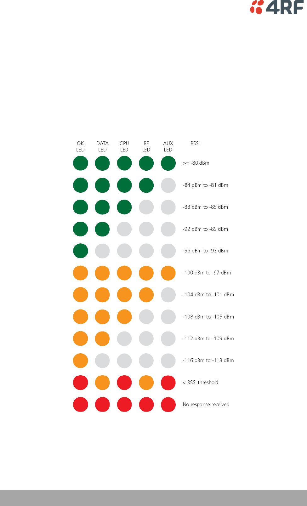
Test Mode
Remote Station and Repeater Station radios have a Test Mode which presents a real time visual display of
the RSSI on the LED Display panel. This can be used to adjust the antenna for optimum signal strength (see
‘Maintenance > Test Mode’ on page 115 for Test Mode options).
To enter Test Mode, press and hold the ENTER button on the radio LED panel until all the LEDs flash green
(about 3 - 5 seconds).
Note: The response time is variable and can be up to 5 seconds.
To exit Test Mode, press and hold the ENTER button until all the LEDs flash red (about 3 – 5 seconds).
The RF LED will be green if the network is operating correctly.
Product Options | 27
Aprisa SR User Manual
4. Product Options
Dual Antenna Port
The standard Aprisa SR uses a one or two frequency ½ duplex transmission mode which eliminates the
need for a duplexer. However, a dual antenna port option is available for separate transmit and receive
antenna connection to support external duplexers or filters. The transmission remains half duplex.
Option Example
Part Number
Single Antenna Port
APSR-N400-012-SO-12-ETAA
Dual Antenna Port
APSR-N400-012-DO-12-ETAA
28 | Product Options
Aprisa SR User Manual
Protected Station
The Aprisa SR Protected Station provides radio and user interface protection for Aprisa SR radios when
configured as a Base Station. The RF ports and interface ports from two standard Aprisa SR Radios are
switched to the standby radio if there is a failure in the active radio.
Option Example
Part Number
Aprisa SR Radio
APSR-N400-012-SO-12-ETAA
Aprisa SR Protected Station
APSR-R400-012-SO-12-ETAA
The Aprisa SR Protected Station is comprised of an Aprisa SR Protection Switch and two standard Aprisa SR
radios. The Aprisa SR radios can be any of the currently available Aprisa SR radio frequency bands, channel
sizes or single / dual antenna port options.
By default, the Aprisa SR Protected Station is configured with the left hand radio (A) designated as the
primary radio and the right hand radio (B) designated as the secondary radio.
Each radio is configured with its own unique IP and MAC address and the address of the partner radio.
On power-up, the primary radio will assume the active role and the secondary radio will assume the
standby role. If, for some reason, only one radio is powered on it will automatically assume the active
role.
Operation
In normal operation, the active radio carries all RS-232 serial and Ethernet traffic over the radio link and
the standby radio is unused with its transmitter turned off. Both radios are continually monitored for
correct operation and alarms are raised if an event occurs.
The active radio sends regular ‘keep alive’ messages to the standby radio to indicate it is operating
correctly. In the event of a failure on the active radio, the RF link and user interface traffic is
automatically switched to the standby radio.
The failed radio can then be replaced in the field without interrupting user traffic (see ‘Replacing a
Protected Station Faulty Radio’ on page 33).

Product Options | 29
Aprisa SR User Manual
Configuration Management
The active and standby radios are separately managed by SuperVisor via the Local and Partner IP
addresses. Changes to the configuration in one radio must be reflected in the partner radio.
Changes to the Network Table are automatically synchronized from the active radio to the standby radio
but the Network Table is only visible on the active radio. This synchronization does not occur if the
Hardware Manual Lock is active.
Switch Over
The switch over to the standby radio can be initiated automatically, on fault detection, or manually via
the Hardware Manual Lock switch on the Protection Switch or the Software Manual Lock from SuperVisor.
Additionally, it is possible to switch over the radios remotely without visiting the station site, via the
remote control connector on the front of the Protection Switch.
On detection of an alarm fault the switch over time is less than 0.5 seconds. Some alarms may take up to
5 seconds to be detected.
The Protection Switch has a switch guard mechanism to prevent protection switch oscillation. This guard
time will block another switch over with 20 seconds of the previous switch over. At the end of the guard
time period, the switching criteria will be evaluated and any protection switch will occur immediately if
necessary.
Switching Criteria
The Protected Station will switch over operation from the active to the standby radio if any of the
configurable alarm events occur or if there is a loss of the ‘keep alive’ signal from the active radio.
It is possible to configure the alarm events which will trigger the switch over. It is also possible to prevent
an alarm event triggering a switch over through the configuration of blocking criteria.
Any of the following alarm events can be set to trigger or prevent switching from the active radio to the
standby radio (see ‘Events > Events Setup’ on page 126).
PA current
Tx AGC
Tx reverse power
Temperature threshold
Thermal shutdown
RSSI threshold
Rx CRC errors
RF no receive data
Ethernet port 1 – no receive data
Ethernet port 1 – data receive errors
Ethernet port 1 - data transmit errors
Ethernet port 2 – no receive data
Ethernet port 2 – data receive errors
Ethernet port 2 - data transmit errors
Serial port – no receive data
Serial port – data receive errors
Component failure
Calibration failure
Configuration not supported
Switch over will not occur if there is a power failure or an active alarm event is detected on the standby
radio which has been configured as a ‘blocking criteria’. Switch over will be initiated once either of these
conditions is rectified, i.e. power is restored or the alarm is cleared.
30 | Product Options
Aprisa SR User Manual
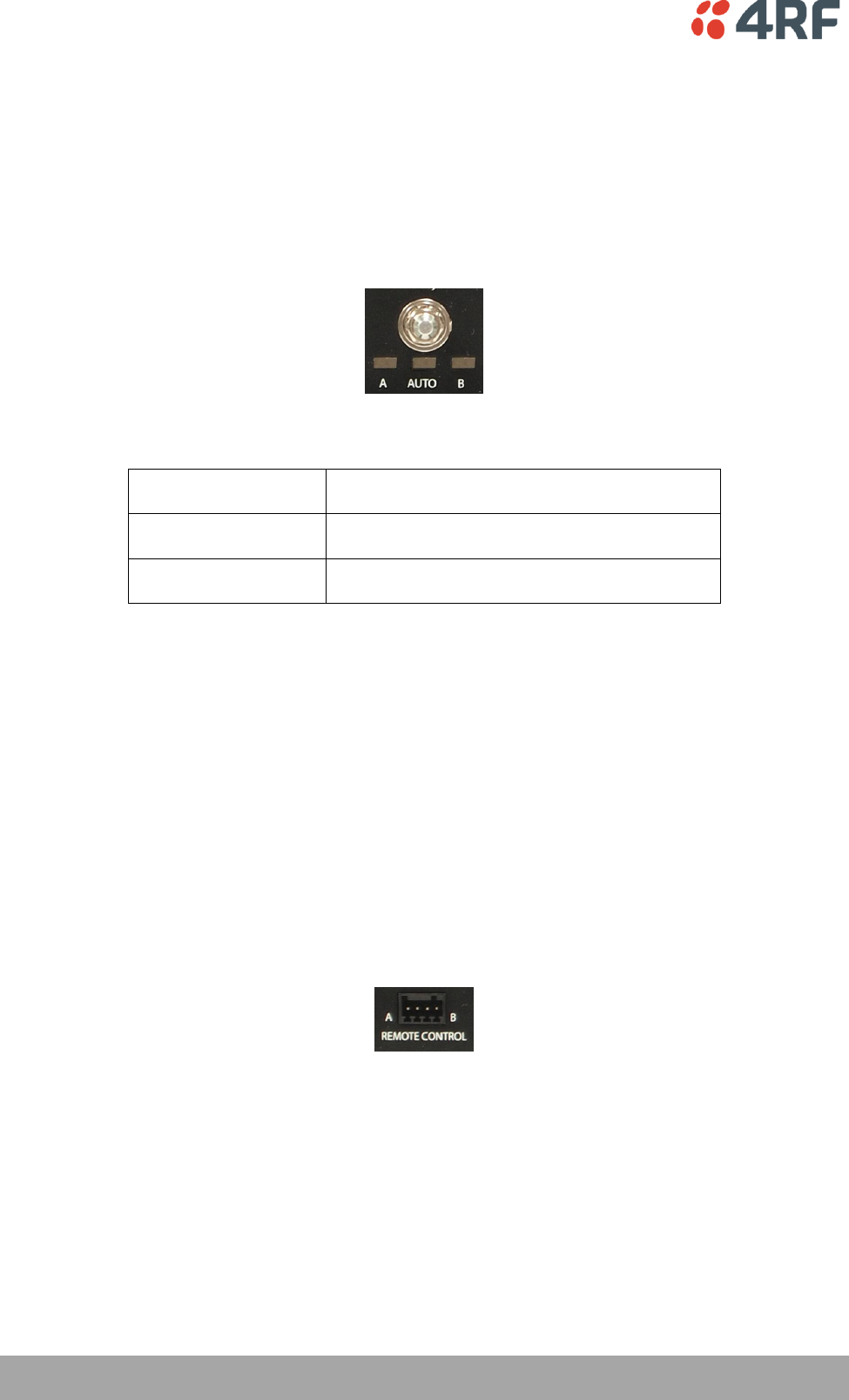
Hardware Manual Lock
The Hardware Manual Lock switch on the Protection Switch provides a manual override of the active /
standby radio.
When this lock is activated, the selected radio (A or B) becomes the active radio regardless of the
Software Manual Lock and the current switching or block criteria.
When the lock is deactivated (set to the Auto position), the protection will become automatic and
switching will be governed by normal switching and blocking criteria.
The state of the lock is indicated by the three LEDs on the Protection Switch:
A LED Orange
Manual Lock asserted and radio A is active
B LED Orange
Manual Lock asserted and radio B is active
Auto LED Green
Manual Lock is in Auto position
Only one of three LEDs will be active at a time.
The Protection Switch also has a Software Manual Lock (see ‘Lock Active’ on page 119). The Hardware
Manual Lock takes precedence over Software Manual Lock if both diagnostic functions are activated i.e. if
the Software Manual Lock is set to ‘Primary’ and the Hardware Manual Lock set to ‘Secondary’, the system
will set the Secondary radio to Active.
When a Hardware Manual Lock is deactivated (set to the Auto position), the Software Manual Lock is re-
evaluated and locks set appropriately.
Remote Control
The switch over to the standby radio can be initiated via the Remote Control connector on the front of the
Protection Switch. This control will only operate if the Hardware Manual Lock switch is set to the Auto
position.
The inputs are logic inputs with 220 Ω pullup to +5 VDC. They require a pull down to ground to activate
the control. The ground potential is available on the connector (see ‘Protection Switch Remote Control
Connections’ on page 143).
Product Options | 31
Aprisa SR User Manual
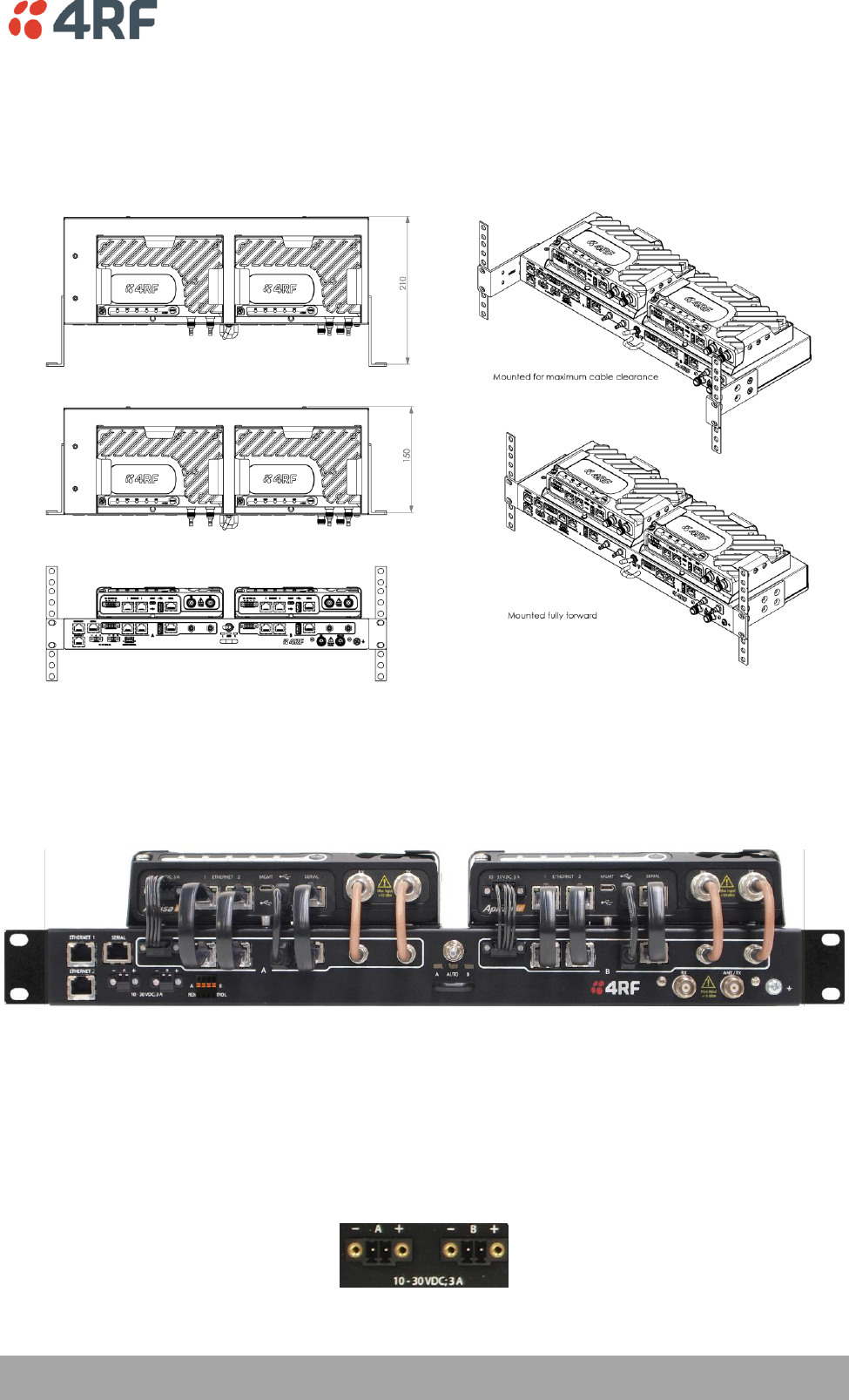
Installation
Mounting
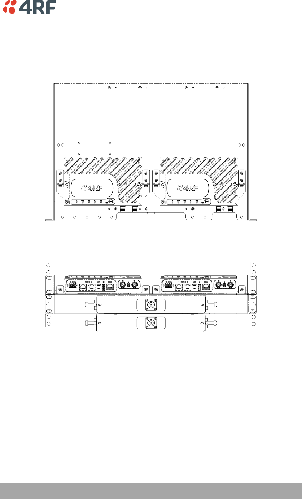
The Aprisa SR Protected Station is designed to mount in a standard 19 inch rack.
Cabling
The Aprisa SR Protected Station is delivered pre-cabled with power, interface, management and RF
cables.
The set of interconnect cables is available as a spare part (see ‘Spares’ on page 34).
Power
A +10.5 to +30 V DC external power source must be connected to both the A and B Phoenix Contact 2 pin
male power connectors. The maximum combined power consumption is 35 Watts.
32 | Product Options
Aprisa SR User Manual
Maintenance
Changing the Protected Station IP Addresses
To change the IP address of a Protected Station radio:
1. Using the Hardware Manual Lock switch, force the primary radio to active.
2. Change the IP address of either or both radios.
3. Change the Partner IP address of either or both radios.
4. Set the Hardware Manual Lock switch to the Auto position.
Protected Station Software Upgrade
The Protected Station software upgrade can be achieved without disruption to traffic.
Assuming the Primary radio is active and the Secondary radio is standby
1. Using the Hardware Manual Lock switch, force the primary radio to active.
2. Carefully remove the Host Port USB cable connecting the secondary radio to the Protection Switch and
insert the USB flash drive with the new software release into the secondary radio Host Port .
3. Power cycle the secondary radio. The radio will be upgraded with the new software.
4. When the secondary radio upgrade is completed, remove the USB flash drive, restore the Host Port
USB cable to Protection Switch, power cycle the secondary radio and wait for it to become standby.
5. Using the Hardware Manual Lock switch, force the secondary radio to active.
6. Carefully remove the Host Port USB cable connecting the primary radio to the Protection Switch and
insert the USB flash drive with the new software release into the primary radio Host Port .
7. Power cycle the primary radio. The radio will be upgraded with the new software.
8. When the primary radio upgrade is completed, remove the USB flash drive, restore the Host Port USB
cable to Protection Switch, power cycle the primary radio and wait for it to become standby.
9. Set the Hardware Manual Lock switch to the Auto position. The secondary radio will remain active and
the primary radio will remain standby. To set the primary radio to active, use the hardware lock
switch to select the primary radio and wait for it to become active, then set the hardware manual
lock switch to the Auto position.

Product Options | 33
Aprisa SR User Manual
Replacing a Protected Station Faulty Radio
Replacing a faulty radio in a Protected Station can be achieved without disruption to traffic.
Assuming that the primary radio is active and the secondary radio is faulty and needs replacement:
1. Ensure the replacement radio has the same version of software installed as the primary radio. If
necessary, upgrade the software in the replacement radio.
2. Set the RF Interface MAC Address (see ‘Maintenance > Advanced’ on page 121). This MAC address is
present on chassis label.
3. Using SuperVisor > Maintenance > Advanced ‘Save Configuration to USB’ and ‘Restore Configuration
from USB’ operation, clone the primary radio’s configuration to the replacement radio.
4. Configure the replacement radio as the secondary radio and setup the other protection parameters
(see ‘Terminal > Operating Mode’ on page 76).
5. Using the Hardware Manual Lock switch, force the primary radio to active.
6. Carefully remove the faulty radio from the protection switch and install the replacement radio.
7. Power on the replacement radio and wait for it to become standby.
8. Set the Hardware Manual Lock switch to the Auto position.
Setting the Software Manual Lock
To make changes remotely to the Protected Station radios, the Software Manual Lock must be set to
prevent switch-over while making the changes (see ‘Lock Active’ on page 119). This procedure should be
followed when making changes that may interrupt traffic or cause a trigger a switch condition.
This procedure assumes that the Hardware Manual Lock is set to the Auto position, and there are no active
switching alarm conditions:
1. Login to the primary radio (left hand radio A by default).
2. Set the Software Manual Lock (Lock Active To) to Primary. The primary radio will become active i.e.
traffic will be switched to the primary radio.
3. Login to the secondary radio (right hand radio B by default).
4. Set the Software Manual Lock (Lock Active To) to Primary. This will prevent the secondary radio from
becoming active.
5. Make the changes to the secondary radio if required.
6. Set the secondary radio Software Manual Lock (Lock Active To) to Automatic.
7. Login to the primary radio (left hand radio A by default).
8. Set the Software Manual Lock (Lock Active To) to Secondary. This will prevent the primary radio from
becoming active.
Note: The Primary radio will become ‘Standby’ and the Secondary radio will become ‘Active’.
9. Make the changes to the primary radio if required.
10. Set the primary radio Software Manual Lock (Lock Active To) to Automatic.

34 | Product Options
Aprisa SR User Manual
Spares
The Aprisa SR Protection Switch is available as a spare part. This spare includes the protection switch and
2 sets of Protection Switch interconnect cables (one set is 7 cables).
Part Number
Part Description
APSP-SPSW
4RF Spare, Aprisa SR, Protection Switch
The set of interconnect cables is available as a spare part (set of 7 cables).
Part Number
Part Description
APSP-SPSC-XS7
4RF Spare, Aprisa SR, Protection Switch Cables, Set Of 7
Replacing a Faulty Protection Switch
Note: Replacing a faulty Protection Switch will disrupt traffic.
Move the radios, the interconnect cables, the interface cables and the power cables to the replacement
Protection Switch.
On both Protected Station radios:
1. Power on the radio and wait for it to become ready.
2. Using SuperVisor > Maintenance > Advanced, enter the RF Interface MAC address shown on the
Protection Switch label (see ‘RF Interface MAC address’ on page 122).
3. Using SuperVisor > Maintenance > Advanced, Decommission the node (see ‘Decommission Node’ on
page 122) and then Discover the Nodes (see ‘Discover Nodes’ on page 122).
Ensure that the Hardware Manual Lock switch is set to the Auto position.
The Aprisa SR Protected Station is now ready to operate.
Product Options | 35
Aprisa SR User Manual
Data Driven Protected Station
The Aprisa SR Data Driven Protected Station provides radio and RS-232 serial port user interface
protection for Aprisa SR radios when configured as a Base Station.
Option Example
Part Number
Aprisa SR Radio (Dual Antenna Port option)
APSR-N400-012-DO-12-ETAA
Aprisa SR Data Driven Protected Station
APSR-D400-012-DO-12-ETAA
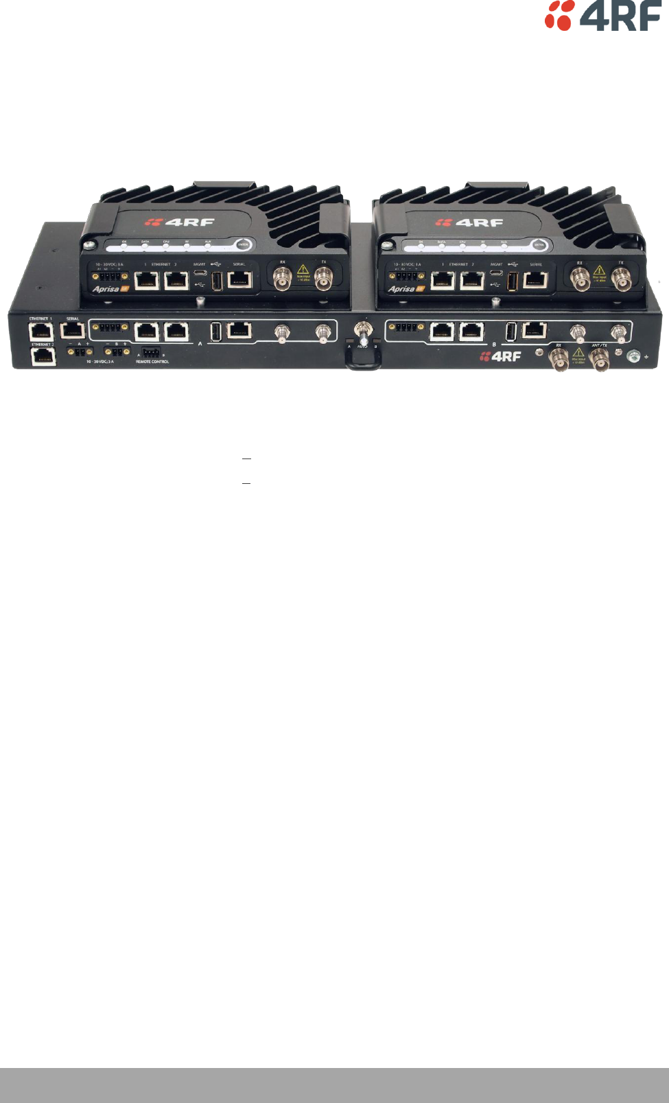
The Aprisa SR Data Driven Protected Station shown is comprised of two standard Aprisa SR dual antenna
port option radios and two external duplexers mounted on 19" rack mounting shelves.
The Aprisa SR radios can be any of the currently available Aprisa SR radio frequency bands, channel sizes
or single / dual antenna port options.
By default, the Aprisa SR Data Driven Protected Station is configured with the left hand radio (A)
designated as the primary radio and the right hand radio (B) designated as the secondary radio.
Each radio is configured with its own unique IP and MAC address and the address of the partner radio.
On power-up, the primary radio will assume the active role and the secondary radio will assume the
standby role. If, for some reason, only one radio is powered on it will automatically assume the active
role.
Operation
The active radio is determined explicitly by which radio receives data on its RS-232 serial port input from
the interface.
The active radio carries all RS-232 serial traffic over its radio link and the standby radio is unused with its
transmitter turned off.
If data is received on the RS-232 serial port interface input of the standby radio, it will immediately
become the active radio and the radio which was active will become the standby radio.

36 | Product Options
Aprisa SR User Manual
Switch Over
The active radio is determined explicitly by which radio receives data on its RS-232 serial port.
The switching and blocking criteria used for the standard Protected Station do not apply. This means that
events and alarms on the unit are not used as switching criteria.
Configuration Management
The active and standby radios are separately managed by SuperVisor via the Local and Partner IP
addresses. Changes to the configuration in one radio must be reflected in the partner radio.
Changes to the Network Table are automatically synchronized from the active radio to the standby radio
but the Network Table is only visible on the active radio.
Product Options | 37
Aprisa SR User Manual
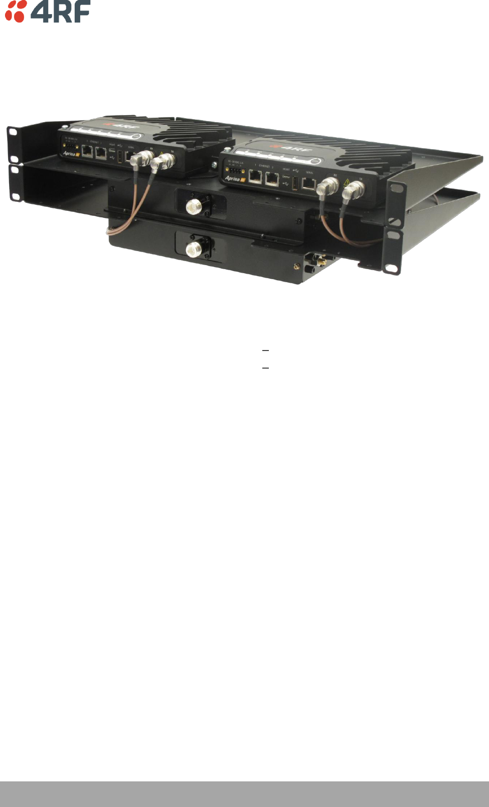
Installation
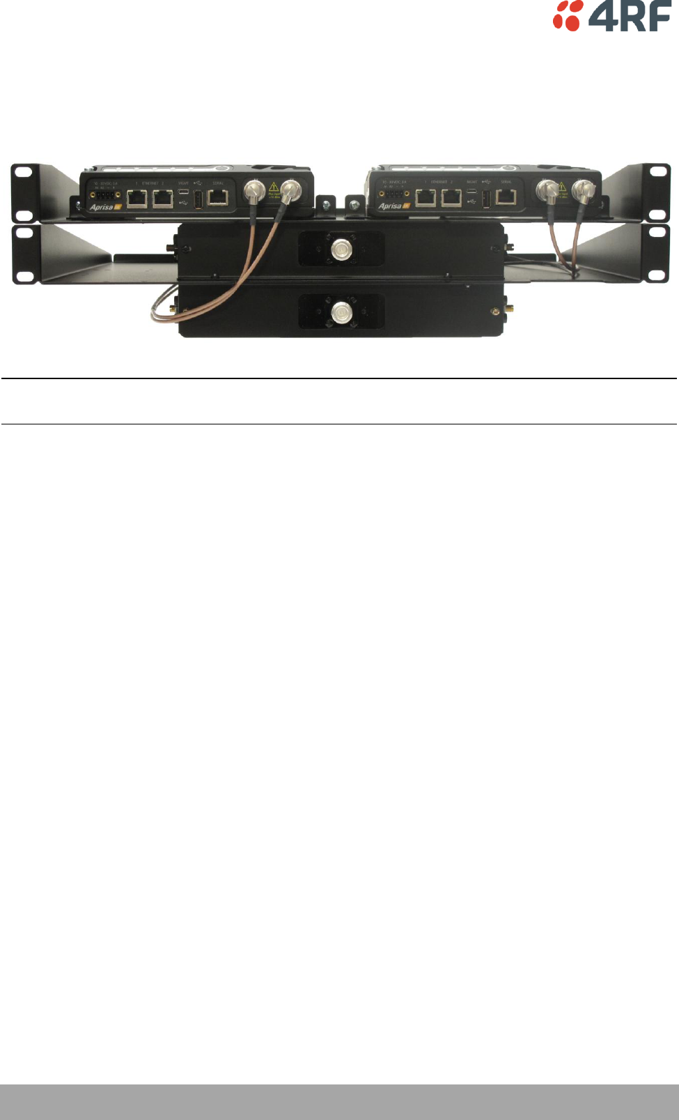
Mounting
The Aprisa SR Data Driven Protected Station is designed to mount in a standard 19” rack on two 1U rack
mounting shelves.
38 | Product Options
Aprisa SR User Manual
Cabling
The Aprisa SR Data Driven Protected Station is delivered with the radios, duplexers, rack mounting shelves
and RF cables.
Note: The picture demonstrates the RF cabling but the product is delivered with the cables separately
packaged.
The set of interconnect cables is available as a spare part.
Power
A +10.5 to +30 V DC external power source must be connected to both the A and B Phoenix Contact 4 pin
male power connectors. The maximum combined power consumption is 35 Watts.
Implementing the Network | 39
Aprisa SR User Manual
5. Implementing the Network
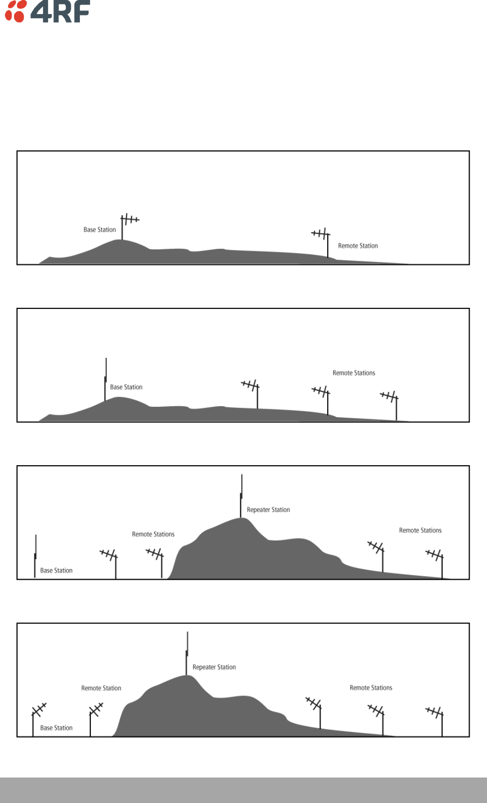
Network Topologies
The following are examples of typical Network Topologies:
Point-To-Point Network
Point-to-Multipoint Network
Point-to-Multipoint with Repeater 1
Point-to-Multipoint with Repeater 2

40 | Implementing the Network
Aprisa SR User Manual
Initial Network Deployment
Install the Base Station
To install the Base Station in your FAN (Field Area Network):
1. Install the Base Station radio (see ‘Installing the Radio’ on page 50).
2. Set the radio Network ID (FAN) to a unique ID in your entire network (see ‘Terminal > Device’ on page
74).
3. Set the radio IP address (see ‘Terminal > Device’ on page 74).
4. Set the radio frequencies to the frequencies you wish to operate from (see ‘Radio > Basic’ on page
79).
5. Set the radio operating mode to ‘Base Station’ (see ‘Terminal > Operating Mode’ on page 76).
6. Set the radio security settings (see ‘Security > Settings’ on page 104).
Installing the Remote Stations
To install the Remote Stations in your FAN:
1. Install the Remote Station radio (see ‘Installing the Radio’ on page 50).
2. Set the radio Network ID (FAN) to the same ID as the other stations in the FAN (see ‘Terminal >
Device’ on page 74).
3. Set the radio IP address (see ‘Terminal > Device’ on page 74).
4. Set the radio frequencies to the Base Station / Repeater Station frequencies you wish to operate from
(see ‘Radio > Basic’ on page 79).
5. Set the radio operating mode to ‘Remote Station’ (see ‘Terminal > Operating Mode’ on page 76).
6. Set the radio security settings to the same as the Base Station (see ‘Security > Settings’ on page 104).
The Base Station will automatically allocate a node address to the new Remote Station.
Install a Repeater Station
To install a Repeater Station in your FAN:
1. Install the Repeater Station radio (see ‘Installing the Radio’ on page 50).
2. Set the radio Network ID (FAN) to the same ID as the other stations in the FAN (see ‘Terminal >
Device’ on page 74).
3. Set the radio IP address (see ‘Terminal > Device’ on page 74).
4. Set the radio frequencies to Base Station frequencies you wish to operate from (see see ‘Radio >
Basic’ on page 79).
5. Set the radio operating mode to ‘Repeater Station’ (see ‘Terminal > Operating Mode’ on page 76).
6. Set the radio security settings to the same as the Base Station (see ‘Security > Settings’ on page 104).
7. Increase the radio network radius by one on all stations in the FAN (see ‘Terminal > Device’ on page
74).
The Base Station will automatically allocate a node address to the new Repeater Station.

Implementing the Network | 41
Aprisa SR User Manual
Network Changes
Adding a Repeater Station
To add a Repeater Station to your FAN:
1. Install the Repeater Station radio (see ‘Installing the Radio’ on page 50).
2. Set the radio Network ID (FAN) to the same ID as the other stations in the FAN (see ‘Terminal >
Device’ on page 74).
3. Set the radio IP address (see ‘Terminal > Device’ on page 74).
4. Set the radio frequencies to the Base Station frequencies you wish to operate from (see ‘Radio >
Basic’ on page 79).
5. Set the radio operating mode to ‘Repeater Station’ (see ‘Terminal > Operating Mode’ on page 76).
6. Increase the radio network radius by one on all stations in the FAN (see ‘Terminal > Device’ on page
74).
The Base Station will automatically allocate a node address to the new Repeater Station.
To remove a Repeater Station from your FAN:
1. Turn the power off on the Remote Station radios operating from the Repeater Station radio you wish
to remove.
2. Turn the power off on the Repeater Station radio you wish to remove.
3. Decrease the network radius by one on all stations in the FAN (see ‘Terminal > Device’ on page 74).
Adding a Remote Station
To add a Remote Station to your FAN:
1. Install the Remote Station radio (see ‘Installing the Radio’ on page 50).
2. Set the radio Network ID (FAN) to the same ID as the other stations in the FAN (see ‘Terminal >
Device’ on page 74).
3. Set the radio IP address (see ‘Terminal > Device’ on page 74).
4. Set the radio frequencies to the Base Station / Repeater Station frequencies you wish to operate from
(see ‘Radio > Basic’ on page 79).
5. Set the radio operating mode to ‘Remote Station’ (see ‘Terminal > Operating Mode’ on page 76).
The Base Station will automatically allocate a node address to the new Remote Station.
To remove a Remote Station from your FAN:
1. Turn the power off on the Remote Station radio you wish to remove. This is the only action that is
required.
Preparation | 43
Aprisa SR User Manual
6. Preparation
Bench Setup
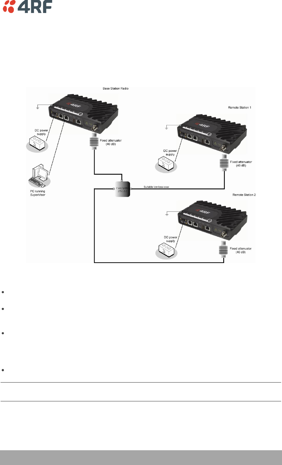
Before installing the links in the field, it is recommended that you bench-test the links. A suggested setup
for basic bench testing is shown below:
When setting up the equipment for bench testing, note the following:
Earthing - each radio should be earthed at all times. The radio earth point should be connected to a
protection earth.
Attenuators - In a bench setup, there should be 60 - 80 dB at up to 1 GHz of 50 ohm coaxial
attenuation, capable of handling the transmit power of +37 dBm (5 W) between the radios’ antenna
connectors.
Splitter – If more than two radios are required in your bench setup, a multi-way splitter is required.
The diagram shows a two way splitter.
This splitter should be 50 ohm coaxial up to 1 GHz and capable of handling the transmit power of +37
dBm (5 W).
Cables - use double-screened coaxial cable that is suitable for use up to 1 GHz at ≈ 1 metre.
CAUTION: Do not apply signals greater than +10 dBm to the antenna connection as they can damage the
receiver.
44 | Preparation
Aprisa SR User Manual
Path Planning
The following factors should be considered to achieve optimum path planning:
Antenna Selection and Siting.
Coaxial Cable Selection.
Linking System Plan.
Antenna Selection and Siting
Selecting and siting antennas are important considerations in your system design.
The antenna choice for the site is determined primarily by the frequency of operation and the gain
required to establish reliable links.
Base or Repeater Station
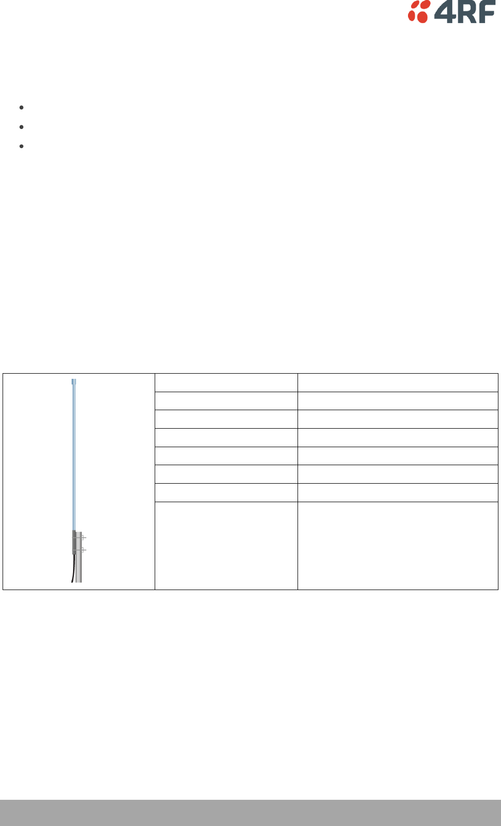
The predominant antenna for a Base Station or a Repeater Station is an omni-directional collinear gain
antenna.
Omni Directional Collinear Antennas
Factor
Explanation
Frequency
Often used in 380-530 MHz bands
Gain
Varies with size (5 dBi to 8 dBi typical)
Wind loading
Minimal
Tower aperture required
Minimal
Size
Range from 2 m to 3 m length
Polarization
Vertical
Preparation | 45
Aprisa SR User Manual
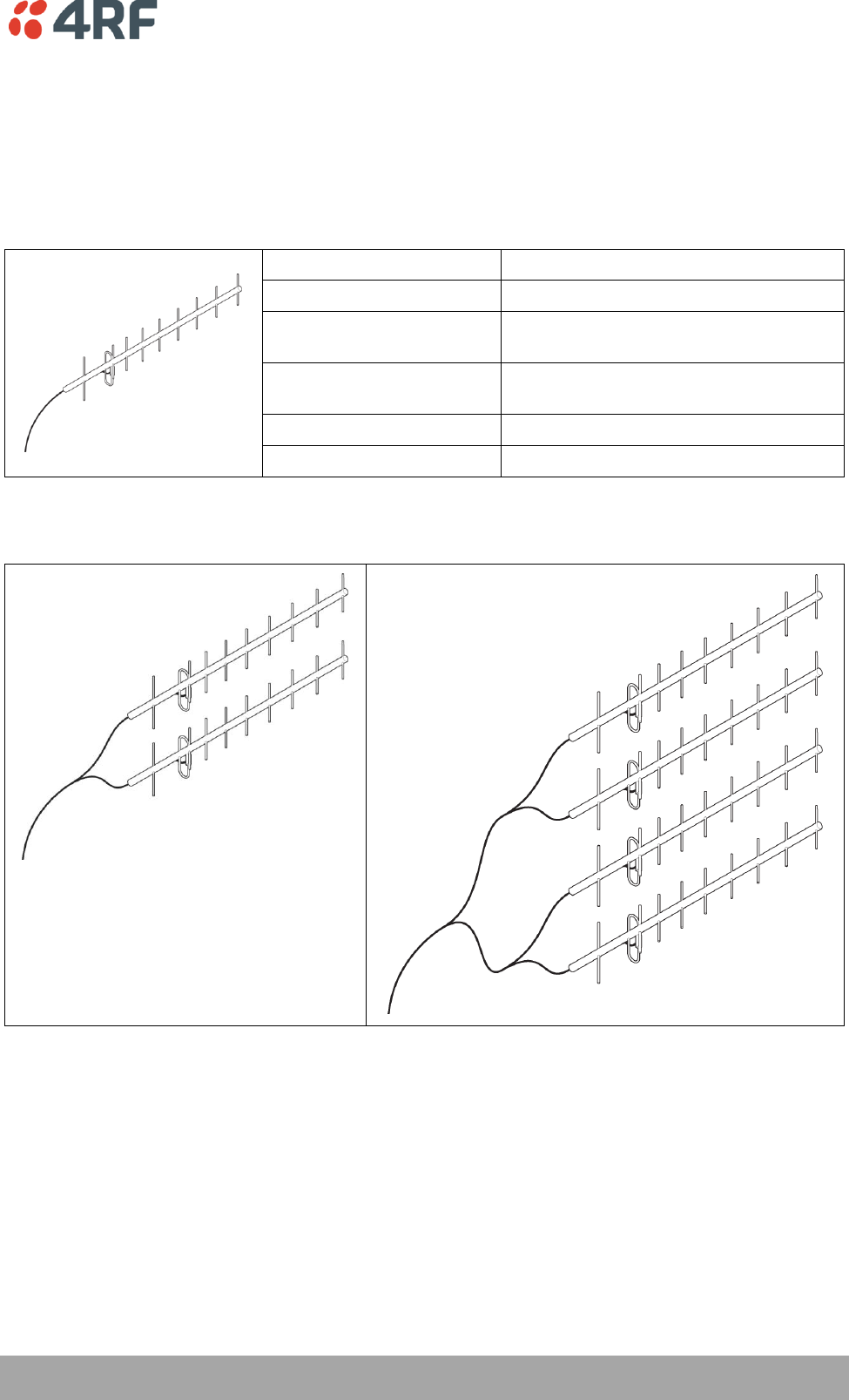
Remote Station
There are two main types of directional antenna that are commonly used for Remote Stations, Yagi and
corner reflector antennas.
Yagi Antennas
Factor
Explanation
Frequency
Often used in 350-600 MHz bands
Gain
Varies with size (typically 11 dBi to 16
dBi)
Stackable gain increase
2 Yagi antennas (+ 2.8 dB)
4 Yagi antennas (+ 5.6 dB)
Size
Range from 0.6 m to 3 m in length
Front to back ratio
Low (typically 18 to 20 dB)
It is possible to increase the gain of a Yagi antenna installation by placing two or more of them in a stack.
The relative position of the antennas is critical.
Example of stacked antennas
46 | Preparation
Aprisa SR User Manual
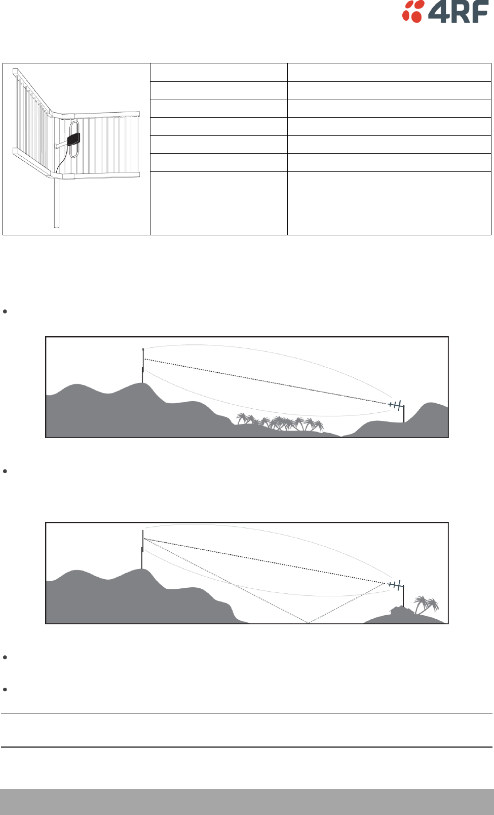
Corner Reflector Antennas
Factor
Explanation
Frequency
Often used in 330-960 MHz bands
Gain
Typically 12 dBi
Size
Range from 0.36 m to 0.75 m in length
Front to back ratio
High (typically 30 dB)
Beamwidth
Broad (up to 60°)
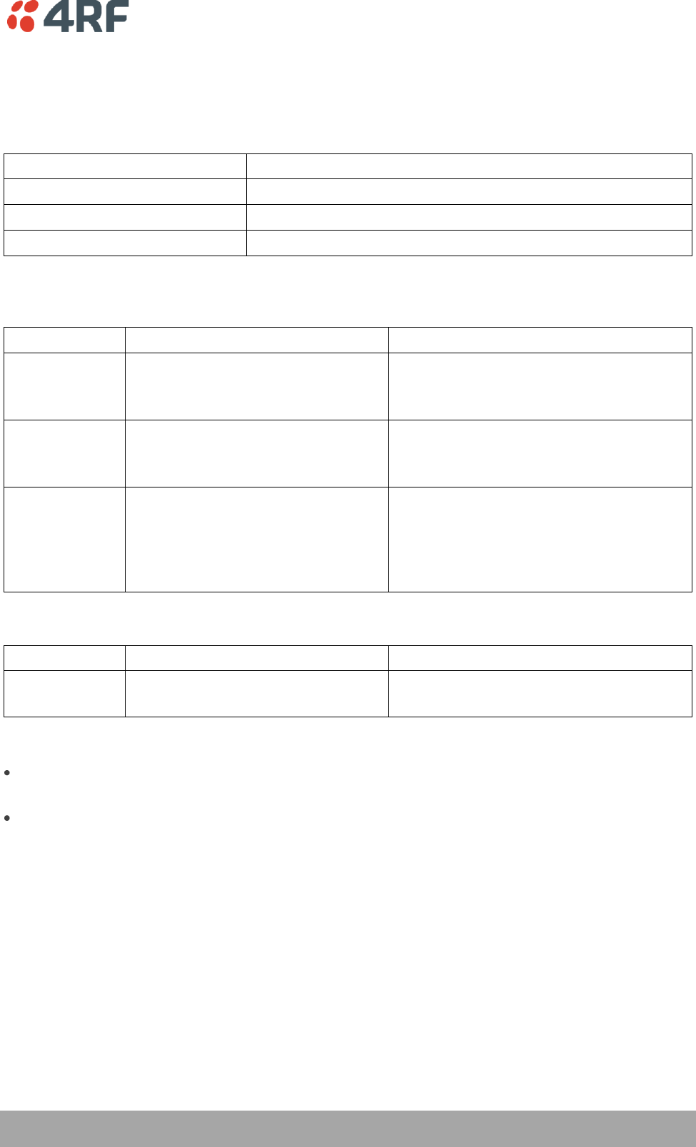
Antenna Siting
When siting antennas, consider the following points:
A site with a clear line of sight to the remote radio is recommended. Pay particular attention to trees,
buildings, and other obstructions close to the antenna site.
Example of a clear line-of-sight path
Any large flat areas that reflect RF energy along the link path, for instance, water, could cause
multipath fading. If the link path crosses a feature that is likely to cause RF reflections, shield the
antenna from the reflected signals by positioning it on the far side of the roof of the equipment
shelter or other structure.
Example of a mid-path reflection path
The antenna site should be as far as possible from other potential sources of RF interference such as
electrical equipment, power lines and roads.
The antenna site should be as close as possible to the equipment shelter.
Note: Wide angle and zoom photographs taken at the proposed antenna location (looking down the
proposed path), can be useful when considering the best mounting positions.
Preparation | 47
Aprisa SR User Manual
Coaxial Feeder Cables
To ensure maximum performance, it is recommended that you use good quality low-loss coaxial cable for
all feeder runs. When selecting a coaxial cable consider the following:
Factor
Effect
Attenuation
Short cables and larger diameter cables have less attenuation
Cost
Smaller diameter cables are cheaper
Ease of installation
Easier with smaller diameter cables or short cables
For installations requiring long feeder cable runs, use the LCF78, LCF12 or CNT-400 feeder cable or
equivalent:
Part Number
Part Description
Specification
RFS LCF78 50JA
Feeder Cable, 7/8’, CELLFLEX, Low
Loss, Std, /m, MOQ 50
Low loss 7/8’ (22.2 mm) feeder cable
Bending radius of 125 mm min
Attenuation of 2.5 dB / 100m @ 450 MHz
RFS LCF12 50J
Feeder Cable, 1/2’, CELLFLEX, Low
Loss, Std, /m, MOQ 50
Low loss 0.5’ (12.7 mm) feeder cable
Bending radius of 125 mm min
Attenuation of 4.7 dB / 100m @ 450 MHz
RFI CNT 400
Feeder, CNT-400, 10.8mm, Double
Shielded Solid Polyethylene
Low loss 0.4’ (10.8 mm) feeder cable
UV protected black Polyethylene, bonded
AL tape outer conductor
Bending radius of 30 mm min
Attenuation of 8.8 dB / 100m @ 450 MHz
For installations requiring short feeder cable runs, use the RFI 8223 feeder cable or equivalent:
Part Number
Part Description
Specification
RFI 8223
Feeder, RG 223 5.4mm d, Double
Shielded Solid Polyethylene
Bending radius of 20 mm min
Attenuation of 30.5 dB / 100m @ 450 MHz
When running cables:
Run coaxial feeder cable from the installation to the antenna, ensuring you leave enough extra cable
at each end to allow drip loops to be formed.
Terminate and ground the feeder cables in accordance with the manufacturers' instructions. Bond the
outer conductor of the coaxial feeder cables to the base of the tower mast.
Linking System Plan
All of the above factors combine in any proposed installation to create a Linking System Plan. The Linking
System Plan predicts how well the radios will perform after it is installed.
Use the outputs of the Linking System Plan during commissioning to confirm the radios have been installed
correctly and that it will provide reliable service.
48 | Preparation
Aprisa SR User Manual
Site Requirements
Power Supply
Ensure a suitable power supply is available for powering the radio.
The nominal input voltage for a radio is +13.8 VDC (negative earth) with an input voltage range of +10 to
+30 VDC. The maximum power input is 30 W.
WARNING:
Before connecting power to the radio, ensure that the radio is grounded via the
negative terminal of the DC power connection.
Equipment Cooling
If the Aprisa SR is operated in an environment where the ambient temperature exceeds 50°C, the Aprisa
SR convection air flow over the heat sinks must be considered.
The environmental operating conditions are as follows:
Operating temperature
-40 to +70˚ C
Storage temperature
-40 to +80˚ C
Humidity
Maximum 95% non-condensing
WARNING:
If the Aprisa SR is operated in an environment where the ambient temperature
exceeds 50°C, the Aprisa SR must be installed within a restricted access location to
prevent human contact with the enclosure heatsink.
Preparation | 49
Aprisa SR User Manual
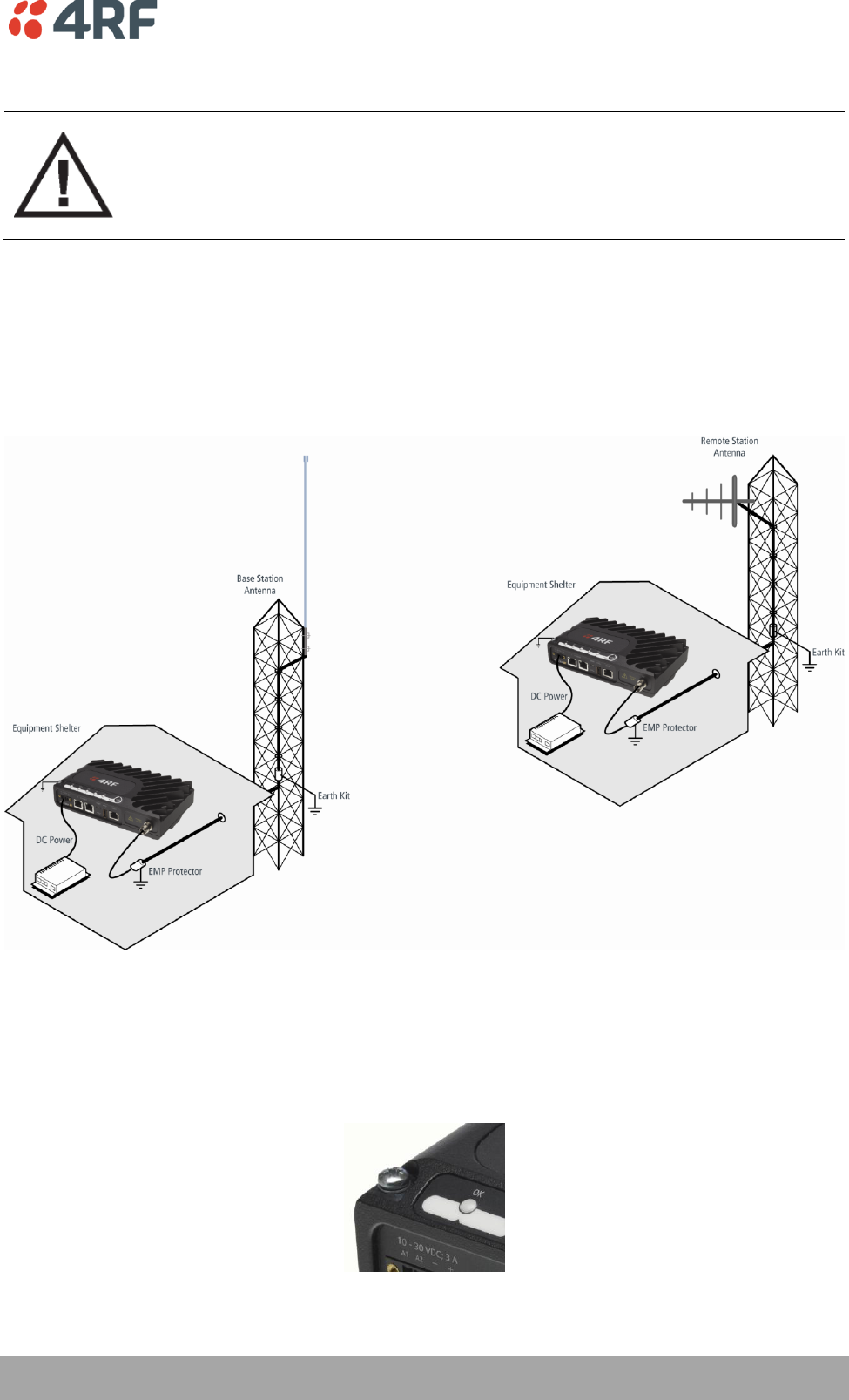
Earthing and Lightning Protection
WARNING:
Lightning can easily damage electronic equipment.
To avoid this risk, install primary lightning protection devices on any interfaces that
are reticulated in the local cable network.
You should also install a coaxial surge suppressor on the radio antenna port.
Feeder Earthing
Earth the antenna tower, feeders and lightning protection devices in accordance with the appropriate
local and national standards. The diagram below shows the minimum requirements.
Use grounding kits as specified or supplied by the coaxial cable manufacturer to properly ground or bond
the cable outer.
Radio Earthing
The Aprisa SR has an earth connection point on the top left of the enclosure. A M4 8mm pan pozi machine
screw and a M4 lock washer is supplied fitted to the radio. This can be used to earth the enclosure to a
protection earth.
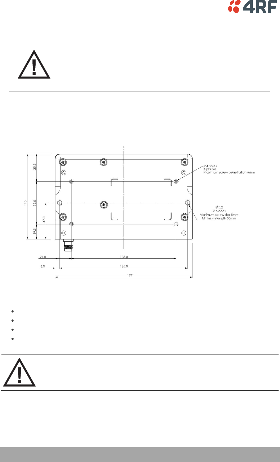
50 | Installing the Radio
Aprisa SR User Manual
7. Installing the Radio
CAUTION:
You must comply with the safety precautions in this manual or on the product
itself.
4RF Communications does not assume any liability for failure to comply with
these precautions.
Mounting
The Aprisa SR has four threaded holes (M4) in the enclosure base and two holes (5.2 mm) through the
enclosure for mounting.
Mounting options include:
DIN rail mounting with the Aprisa SR DIN Rail Mounting Bracket.
Rack shelf mounting.
Wall mounting.
Outdoor enclosure mounting.
WARNING:
If the Aprisa SR is operated in an environment where the ambient temperature
exceeds 50°C, the Aprisa SR must be installed within a restricted access location to
prevent human contact with the enclosure heatsink.
Required Tools
No special tools are needed to install the radio.
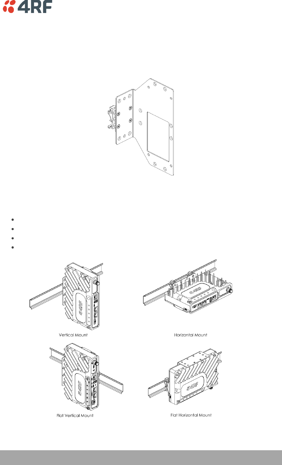
Installing the Radio | 51
Aprisa SR User Manual
DIN Rail Mounting
The Aprisa SR has an optional accessory part to enable the mounting on a standard DIN rail:
Part Number
Part Description
APSA-MBRK-DIN
4RF Aprisa SR Acc, Mounting, Bracket, DIN Rail
The Aprisa SR is mounted into the DIN rail mounting bracket using the four M4 threaded holes in the Aprisa
SR enclosure base. Four 8 mm M4 pan pozi machine screws are supplied with the bracket.
The Aprisa SR DIN rail mounting bracket can be mounted in four positions on a horizontal DIN rail:
Vertical Mount (vertical enclosure perpendicular to the mount).
Horizontal Mount (horizontal enclosure perpendicular to the mount).
Flat Vertical Mount (vertical enclosure parallel to the mount).
Flat Horizontal Mount (horizontal enclosure parallel to the mount).
The DIN rail mounting bracket has two clips which are positioned to allow for the four mounting positions.
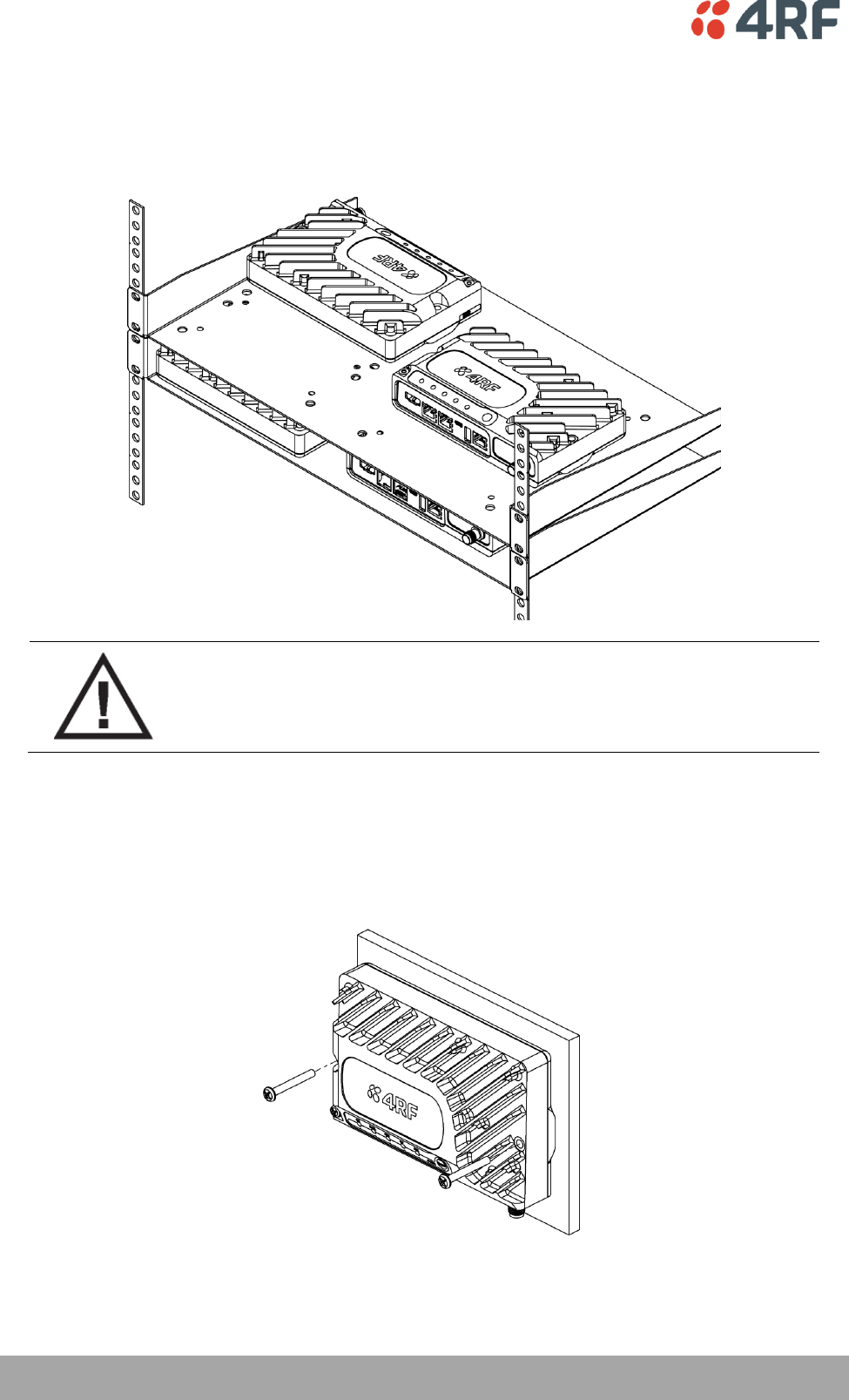
52 | Installing the Radio
Aprisa SR User Manual
Rack Shelf Mounting
The Aprisa SR can be mounted on a rack mount shelf using the four M4 threaded holes in the Aprisa SR
enclosure base. The following picture shows Aprisa SR mounted on 1 RU rack mounted shelves.
WARNING:
If the Aprisa SR is operated in an environment where the ambient temperature
exceeds 50°C, the Aprisa SR convection air flow over the heat sinks must be
considered.
Wall Mounting
The Aprisa SR can be mounted on a wall using the two holes through the enclosure (5.2 mm diameter).
Typically, M5 screws longer than 35 mm would be used.
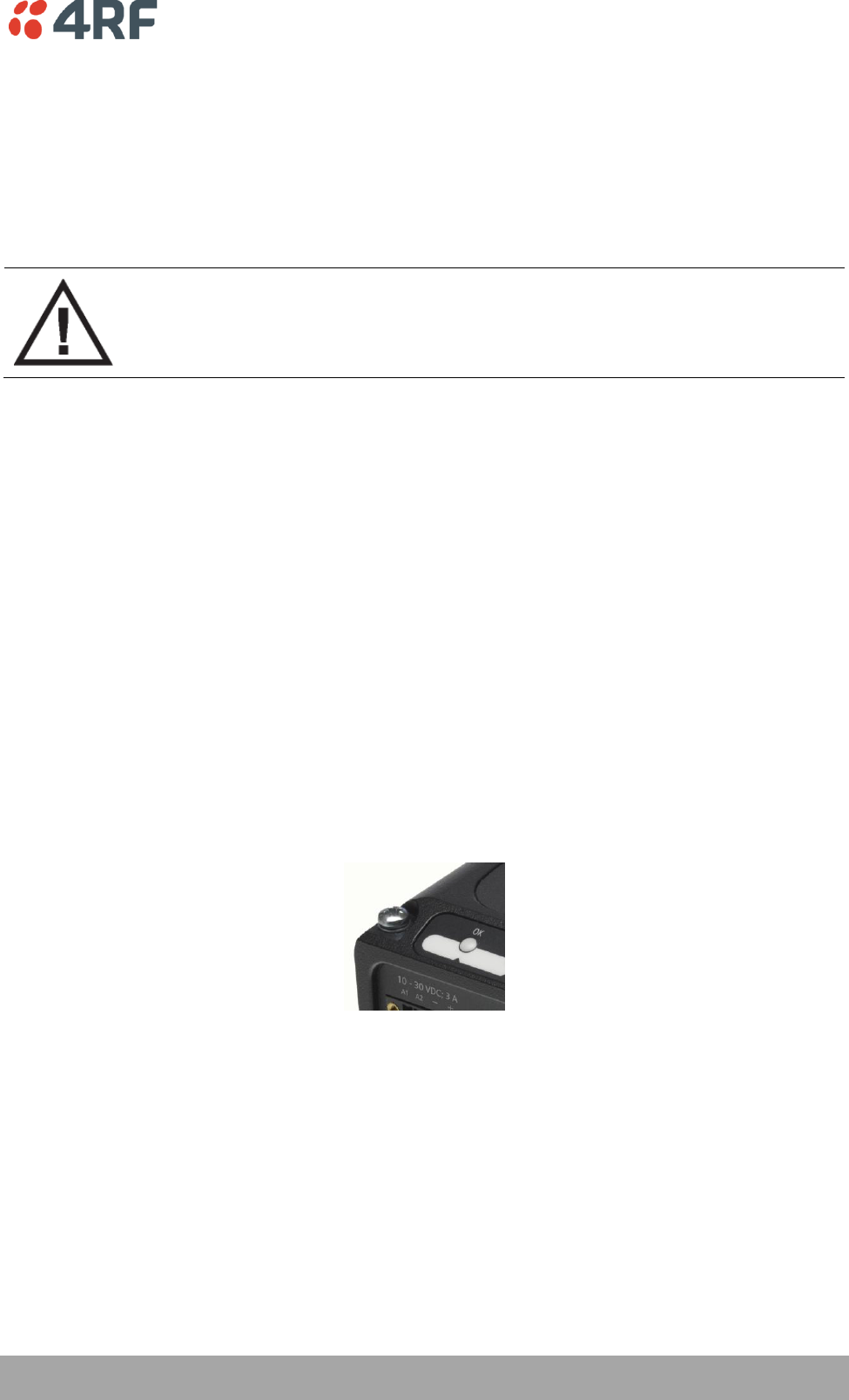
Installing the Radio | 53
Aprisa SR User Manual
Installing the Antenna and Feeder Cable
Carefully mount the antenna following the antenna manufacturers' instructions. Run feeder cable from the
antenna to the radio location.
Lightning protection must be incorporated into the antenna system (see ‘Earthing and Lightning
Protection’ on page 49).
WARNING:
When the link is operating, there is RF energy radiated from the antenna.
Do not stand in front of the antenna while the radio is operating (see the ‘RF
Exposure Warning’ on page 3).
Fit the appropriate male or female connector (usually N-type) to the antenna feeder at the antenna end.
Carefully follow the connector manufacturers' instructions.
Securely attach the feeder cable to the mast and cable trays using cable ties or cable hangers. Follow the
cable manufacturer's recommendations about the use of feeder clips, and their recommended spacing.
Connect the antenna and feeder cable. Weatherproof the connection with a boot, tape or other approved
method.
The Aprisa SR antenna connection is a TNC female connector so the feeder / jumper must be fitted with a
TNC male connector.
If a jumper is used between the feeder and the radio, connect a coaxial surge suppressor or similar
lightning protector between the feeder and jumper cables (or at the point where the cable enters the
equipment shelter). Connect the feeder cable to the antenna port on the radio.
Earth the case of the lightning protector to the site Lightning Protection Earth.
The Aprisa SR has an earth connection point on the top left of the enclosure. A M4 8mm pan pozi machine
screw and a M4 lock washer is supplied fitted to the radio. This can be used to earth the enclosure to a
protection earth.
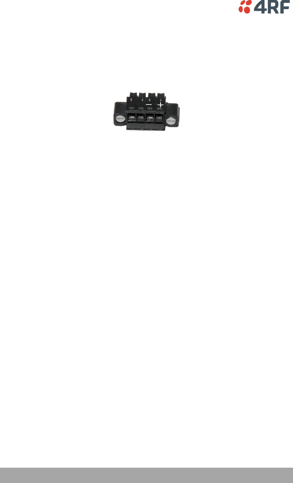
54 | Installing the Radio
Aprisa SR User Manual
Connecting the Power Supply
The nominal input voltage for a radio is +13.8 VDC (negative earth) with an input voltage range of +10 to
+30 VDC. The maximum power input is 30 W.
The power connector required is a Phoenix Contact 4 pin female screw fitting part MC 1.5/ 4-STF-3.5.
This connector is supplied fitted to the radio.
The negative supply of the Aprisa SR power connection is internally connected to the Aprisa SR enclosure.
Power must be supplied from a Negative Earthed power supply.
Wire your power source to power connector and plug the connector into the radio. The connector screws
can be fastened to secure the connector.
Additional Phoenix Contact 4 pin female power connectors can be ordered from 4RF:
Part Number
Part Description
APSA-CPH4-FEM-01
4RF Aprisa SR Acc, Connector, Phoenix 4 pin, Female, 1 item
Turn your power source on.
All the radio LEDs will flash orange for one second and then the OK, DATA and CPU LEDs will light green,
the RF LED will light orange and the AUX LED will be off.
The Aprisa SR radio is ready to operate.
The RF LED will light green when the radio is registered with the FAN.
If the LEDs fail to light, carefully check the supply polarity. If the power supply connections have been
accidentally reversed, internal fuses will have blown to protect the unit.
Spare fuses are contained within the radio, see ‘Spare Fuses’on page 55 for instructions on how to locate
and replace the fuses.
External Power Supplies
The following external power supplies are available from 4RF as accessories:
Part Number
Part Description
APSA-P230-030-24-TS
4RF Aprisa SR Acc, PSU, 230 VAC, 30W, 24 VDC, -10 to +60C
APSA-P230-048-24-TE
4RF Aprisa SR Acc, PSU, 230 VAC, 48W, 24 VDC, -20 to +75C
APSA-P230-060-24-TS
4RF Aprisa SR Acc, PSU, 230 VAC, 60W, 24 VDC, -10 to +60C
APSA-P48D-050-24-TA
4RF Aprisa SR Acc, PSU, 48 VDC, 50W, 24 VDC, 0 to +50C
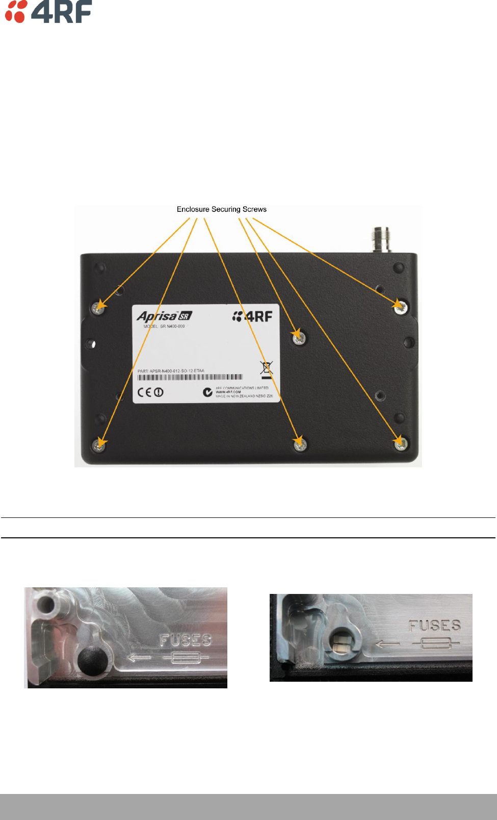
Installing the Radio | 55
Aprisa SR User Manual
Spare Fuses
The Aprisa SR PBA contains two fuses in the power input with designators F2 and F3. Both the positive and
negative power connections are fused. The fuse type is a Littelfuse 0453005 with a rating of 5 A, 125 V,
very fast acting.
To replace the fuses:
1. Remove the input power and antenna cable.
2. Unscrew the enclosure securing screws (posi 2).
2. Separate the enclosure halves.
CAUTION: Antistatic precautions must be taken as the internal components are static sensitive.
3. Access the enclosure spare fuses under the plastic cap.
56 | Installing the Radio
Aprisa SR User Manual
4. Replace the two fuses.
5. Close the enclosure and tighten the screws.
Note: Is it critical that the screws are re-tightened to 1 Nm. The transmitter adjacent channel
performance can be degraded if the screws are not tightened correctly.
Additional Spare Fuses
Additional spare fuses can be ordered from 4RF:
Part Number
Part Description
APSA-FNAN-453-05-02
4RF Aprisa SR Acc, Fuse, Nano SMF, 453 Series, 5A, 2 items

Managing the Radio | 57
Aprisa SR User Manual
8. Managing the Radio
SuperVisor
The Aprisa SR contains an embedded web server application (SuperVisor) to enable element management
with any major web browser (such as Mozilla Firefox, Microsoft® Internet Explorer).
SuperVisor enables operators to configure and manage the Aprisa SR Base Station radio and repeater /
Remote Station radios over the radio link.
The key features of SuperVisor are:
Manage the entire FAN (Field Area Network) from the Base Station connection.
View and set standard radio configuration parameters, including frequencies, transmit power,
channel access, serial, Ethernet and USB port settings.
Set radio operating mode, whether Base Station, Remote Station or Repeater Station.
Set and view security parameters.
Display performance and alarm information, including RSSI, alarm status, time-stamped events,
and alarm parameters.
Connecting to SuperVisor
The predominant management connection to the Aprisa SR radio is with an Ethernet interface using
standard IP networking. There should be only one Ethernet connection from any radio in the FAN to the
management network.
The Aprisa SR has a factory default IP address of 169.254.50.10 with a subnet mask of 255.255.0.0. This is
an IPv4 Link Local (RFC3927) address which simplifies the connection to a PC.
Each radio in the FAN must be set up with a unique IP address on the same subnet.
The Aprisa SR Protected Station radio A (left radio) has a factory default IP address of 169.254.50.10 and
radio B (right radio) has a factory default IP address of 169.254.50.20, both with a subnet mask of
255.255.0.0.
To change the Aprisa SR IP address:
Set up your PC for a compatible IP address e.g. 169.254.50.1 with a subnet mask of 255.255.0.0.
Connect your PC network port to one of the Aprisa SR Ethernet ports.
Open a browser and enter http:// 169.254.50.10.
Login to the radio with the default Username ‘admin’ and Password ‘admin’.
Change the IP address to conform to the network plan in use.
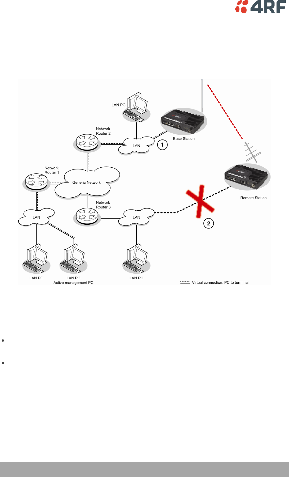
58 | Managing the Radio
Aprisa SR User Manual
Management PC Connection
The active management PC must only have one connection to the FAN as shown by path . There should
not be any alternate path that the active management PC can use via an alternate router or alternate LAN
that would allow the management traffic to be looped as shown by path .
When logging into a FAN, it is important to understand the relationship between the Local Radio and the
Remote Radios.
The Local Radio is the radio that your IP network is physically connected to.
If the Local Radio is a Base Station, SuperVisor manages the Base Station and all the Repeater Stations
and Remote Stations in the FAN.
If the Local Radio is a Remote Station or Repeater Station, SuperVisor only manages the Remote /
Repeater Station radio logged into.

Managing the Radio | 59
Aprisa SR User Manual
PC Settings for SuperVisor
To change the PC IP address:
If your PC has previously been used for other applications, you may need to change the IP address and the
subnet mask settings. You will require Administrator rights on your PC to change these.
Windows XP example: Configure IP settings
1. Open the 'Control Panel'.
2. Open 'Network Connections' and right click on the 'Local Area Connection' and select 'Properties'.
3. Click on the 'General' tab.
4. Click on 'Internet Protocol (TCP/IP)' and click on properties.
5. Enter the IP address and the subnet mask (example as shown).
6. Click 'OK' then close the Control Panel.
If the radio is on a different subnet from the network the PC is on, set the PC default gateway address to
the network gateway address which is the address of the router used to connect the subnets (for details,
consult your network administrator).
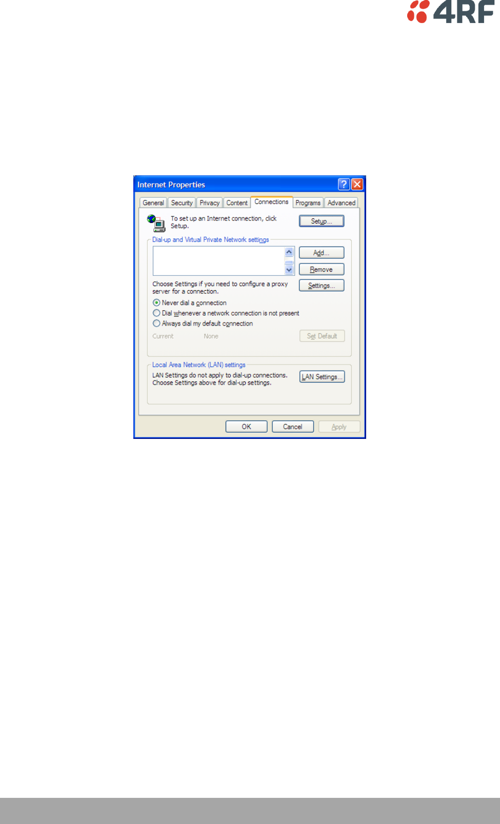
60 | Managing the Radio
Aprisa SR User Manual
To change the PC connection type:
If your PC has previously been used with Dial-up connections, you may need to change your PC Internet
Connection setting to 'Never dial a connection'.
Windows XP example: Configure Windows to Never Dial a Connection
1. Open 'Internet Options' and click on the 'Connections' tab.
2. Click the 'Never dial a connection' option.
3. Click 'OK' then close the Control Panel.
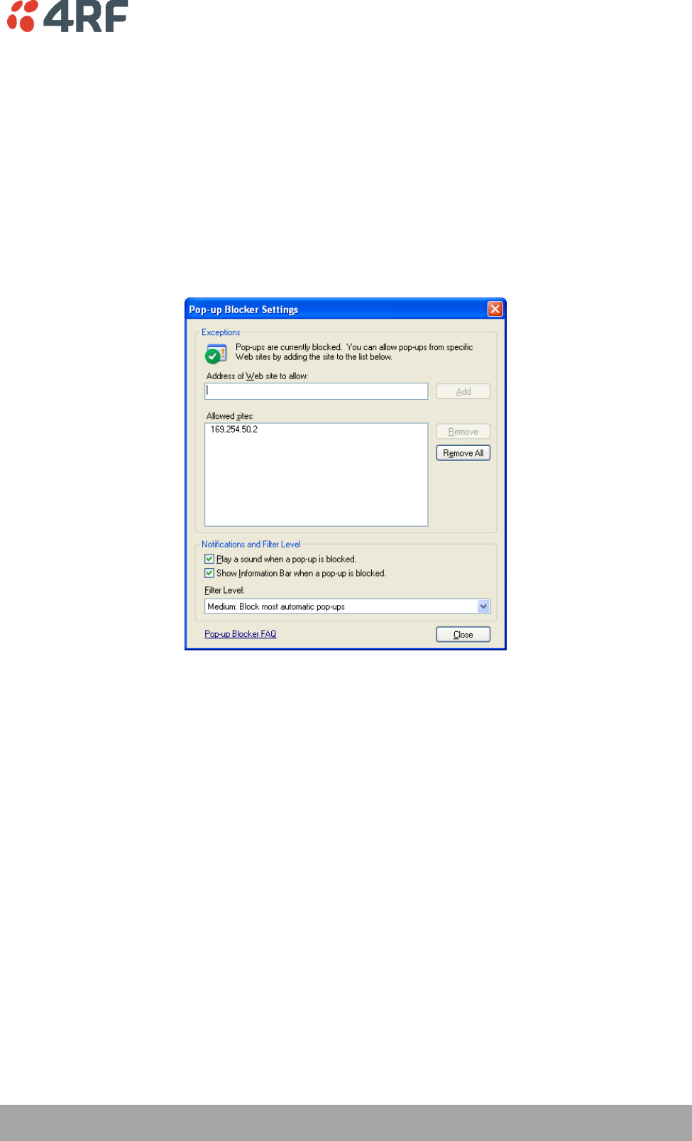
Managing the Radio | 61
Aprisa SR User Manual
To change the PC pop-up status:
Some functions within SuperVisor require Pop-ups enabled e.g. saving a MIB
Windows Internet Explorer example:
1. Open the 'Control Panel'.
2. Open the menu item Tools > Internet Options and click on the 'Privacy' tab.
3. Click on 'Settings'.
4. Set the 'Address of Web site to allow' to the radio address or set the 'Filter Level' to 'Low: Allow Pop-
ups from secure sites' and close the window.
5. Click 'OK' then close the Control Panel.
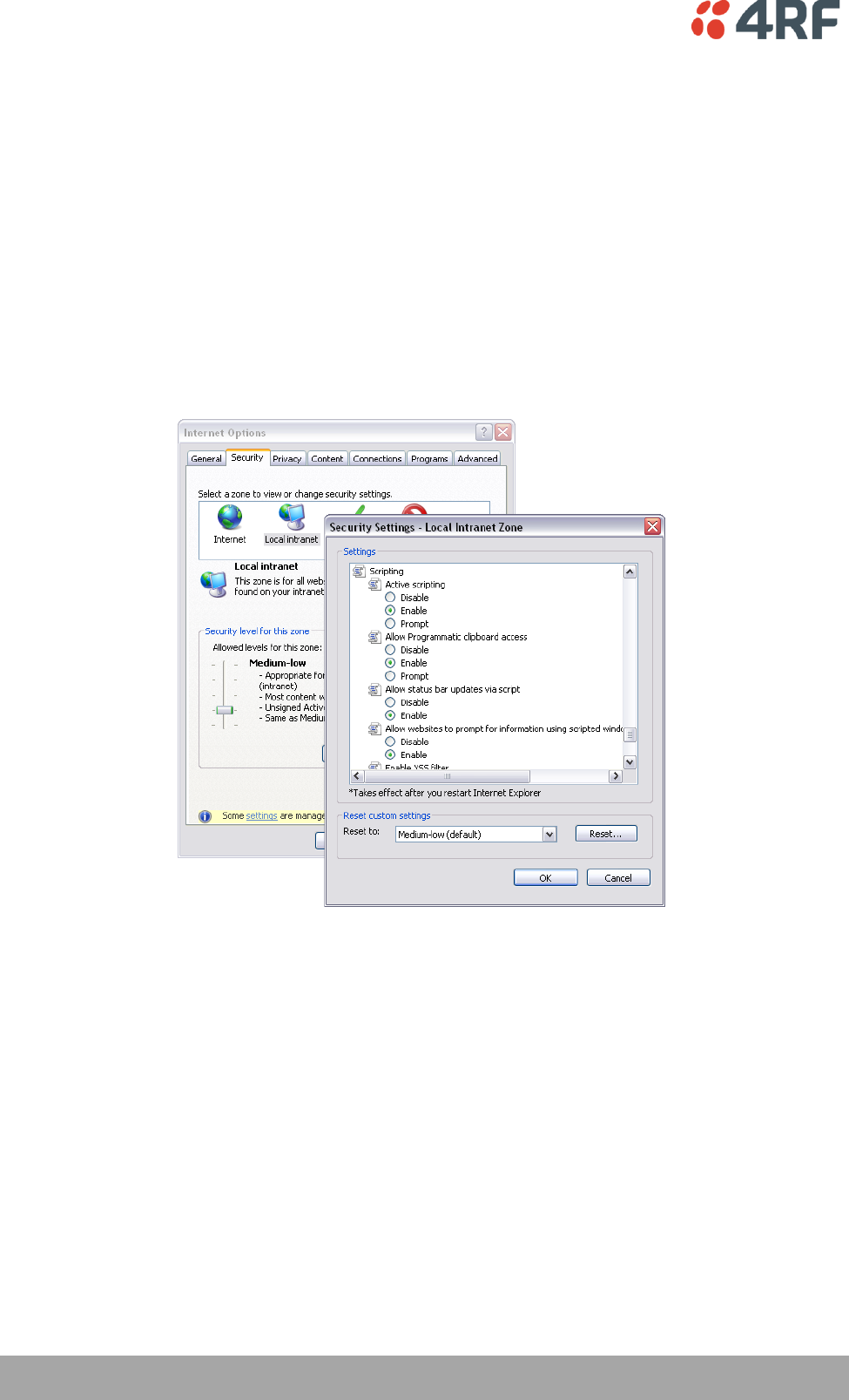
62 | Managing the Radio
Aprisa SR User Manual
To enable JavaScript in the web browser:
Some functions within SuperVisor require JavaScript in the web browser to be enabled.
Windows Internet Explorer example:
1. Open Internet Explorer.
2. Open the menu item Tools > Internet Options and click on the 'Security' tab.
3. Click on 'Local Intranet'.
4. Click on 'Custom Level'.
5. Scroll down until you see section labeled 'Scripting'.
6. Under 'Active Scripting', select 'Enable'.
7. Click 'OK'.
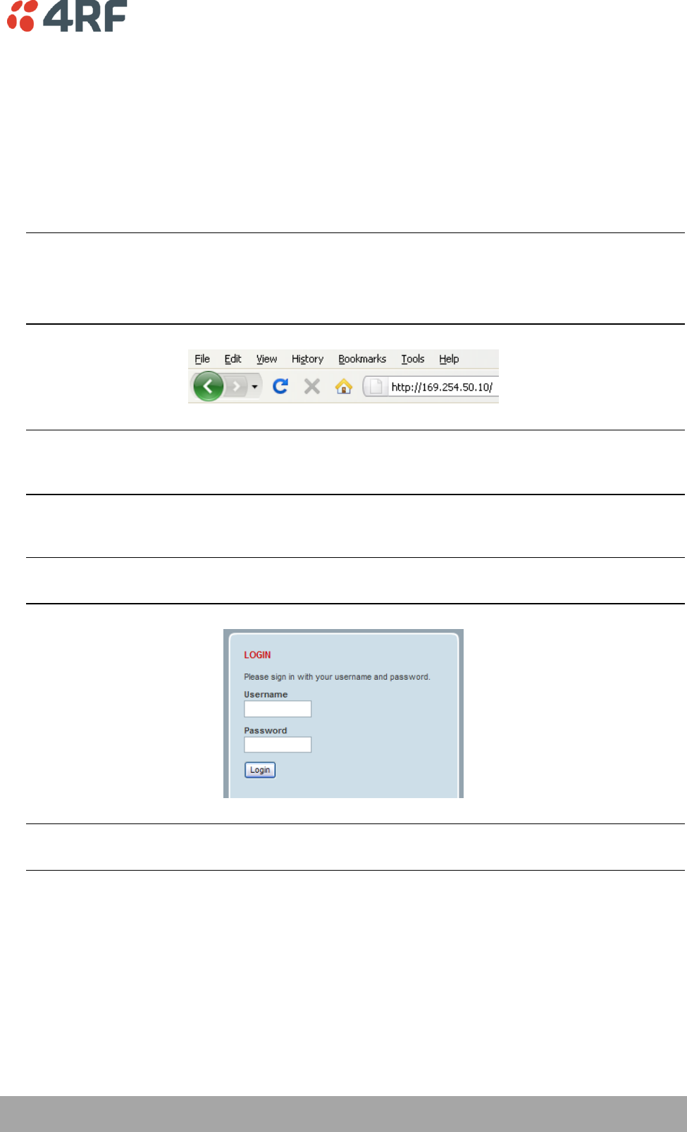
Managing the Radio | 63
Aprisa SR User Manual
Login to SuperVisor
The maximum number of concurrent users that can be logged into a radio is 6.
If SuperVisor is inactive for a period defined by the Inactivity Timeout option on page 111, the radio will
automatically logout the user.
To login to SuperVisor:
1. Open your web browser and enter the IP address of the radio.
Note: If you haven't assigned an IP address to the radio, use the factory default IP address of
169.254.50.10 with a subnet mask of 255.255.0.0.
If you don't know the IP address of the radio, you can determine it using the Command Line Interface
(see ‘Command Line Interface’ on page 131).
Note: The Aprisa SR has a Self Signed security certificate which may cause the browser to prompt a
certificate warning. It is safe to ignore the warning and continue. The valid certificate is ‘Issued By:
4RF-APRISA’ which can be viewed in the browser.
2. Login with the Username and Password assigned to you.
Note: If unique usernames and passwords have not yet been configured, use the default username
‘admin’ and password ‘admin’.
Important: After you login for the very first time, it is recommended that you change the default
admin password for security reasons (see ‘Changing Passwords’ on page 103).
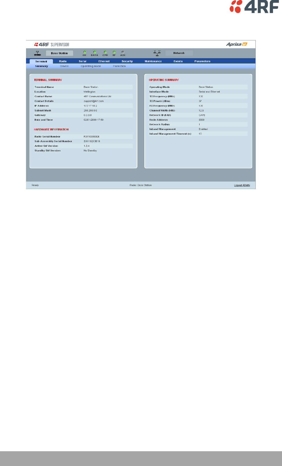
64 | Managing the Radio
Aprisa SR User Manual
If the login is successful, the opening screen will be displayed.
Logout of SuperVisor
As the maximum number of concurrent users that can be logged into a radio is 6, not logging out correctly
can restrict access to the radio until after the timeout period (30 minutes).
Logging out from a radio will logout all users logged in with the same username.
If the SuperVisor window is closed without logging out, the radio will automatically log the user out after a
timeout period of 3 minutes.
To logout of SuperVisor:
Click on the ‘Logout’ button on the Summary Bar.
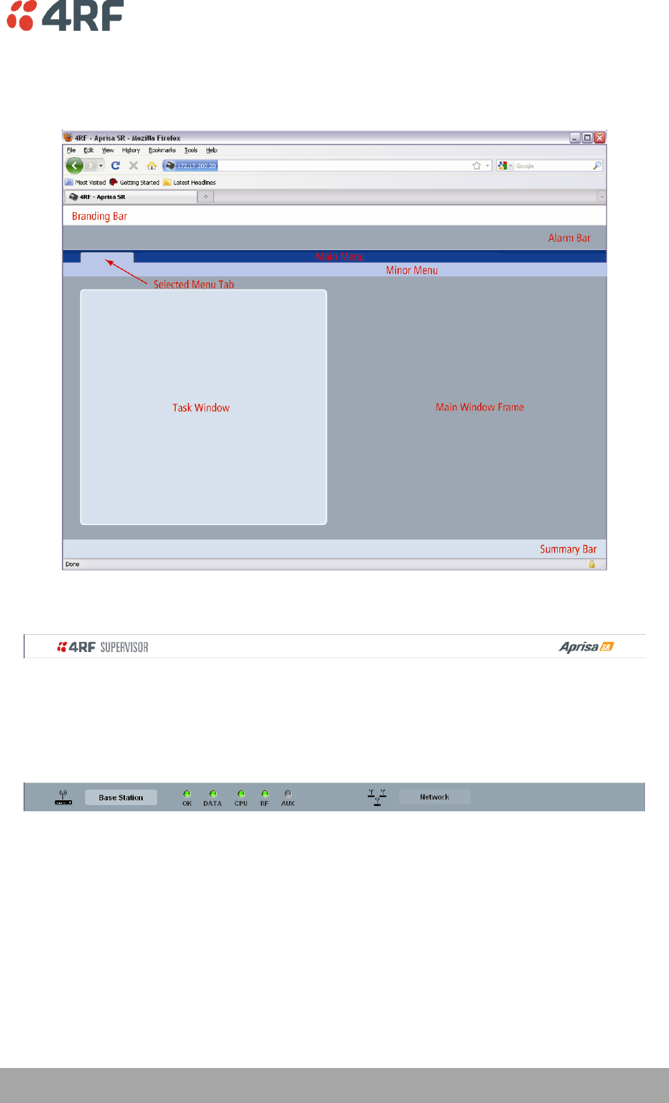
Managing the Radio | 65
Aprisa SR User Manual
SuperVisor Screen Layout
The following shows the components of the SuperVisor screen layout:
SuperVisor Branding Bar
The branding bar at the top of the SuperVisor frame shows the branding of SuperVisor on the left and the
product branding on the right.
SuperVisor Alarm Bar
The alarm bar shows the name of the radio terminal that SuperVisor is logged into (the local radio) on the
left.
If the local radio is a Base Station, the screen shows the name of the current Remote / Repeater station
(the remote radio) on the right. SuperVisor manages all the Repeater Stations and Remote Stations in the
FAN.
If the local radio is a Remote Station or Repeater Station, the screen shows the name of the Remote /
Repeater station on the left. The right side of the Alarm Bar will be blank. SuperVisor manages only the
Remote / Repeater Station logged into.
The LED alarm indicators reflect the status of the front panel LEDs on the radio.
66 | Managing the Radio
Aprisa SR User Manual
SuperVisor Summary Bar
The summary bar at the bottom of the screen shows:
Position
Function
Left
Busy - SuperVisor is busy retrieving data from the radio that
SuperVisor is logged into.
Ready - SuperVisor is ready to manage the radio.
Middle
Displays the name of the radio terminal that SuperVisor is currently
managing.
Right
The access level logged into SuperVisor. This label also doubles as
the SuperVisor logout button.
SuperVisor Parameter Settings
Changes to parameters settings have no effect until the ‘Save’ button is clicked.
Click the ‘Save’ button to apply the changes or ‘Cancel’ button to restore the current value.

Managing the Radio | 67
Aprisa SR User Manual
SuperVisor Menu
The following is a list of SuperVisor top level menu items for both the Local Terminal and Remote
Terminals:
Local Terminal
Remote Terminal
Network Status
Terminal
Terminal
Radio
Radio
Serial
Serial
Ethernet
Ethernet
Security
Security
Maintenance
Maintenance
Events
Events
Parameters
Parameters
68 | Managing the Radio
Aprisa SR User Manual
SuperVisor Menu Access
The SuperVisor menu has varying access levels dependant on the login User Privileges.
The following is a list of SuperVisor menu items versus user privileges:
Menu Item
View
Technician
Engineer
Admin
Terminal > Summary
Read-Only
Read-Only
Read-Only
Read-Only
Terminal > Device Settings
No Access
Read-Write
Read-Write
Read-Write
Terminal > Operating Mode
No Access
Read-Write
Read-Write
Read-Write
Terminal > Protection
No Access
Read-Write
Read-Write
Read-Write
Radio > Summary
Read-Only
Read-Only
Read-Only
Read-Only
Radio > Basic
No Access
Read-Write
Read-Write
Read-Write
Radio > Channel Access
No Access
Read-Write
Read-Write
Read-Write
Serial > Summary
Read-Only
Read-Only
Read-Only
Read-Only
Serial > Port Settings
No Access
Read-Write
Read-Write
Read-Write
Serial > Flow Control
No Access
Read-Write
Read-Write
Read-Write
Serial > Advanced
No Access
No Access
Read-Write
Read-Write
Ethernet > Summary
Read-Only
Read-Only
Read-Only
Read-Only
Ethernet > Port Setup
No Access
Read-Write
Read-Write
Read-Write
Ethernet > Controller Setup
No Access
Read-Write
Read-Write
Read-Write
Ethernet > L2 Filtering
No Access
No Access
Read-Write
Read-Write
Ethernet > Advanced
No Access
No Access
Read-Write
Read-Write
Security > Summary
Read-Only
Read-Only
Read-Only
Read-Only
Security > Users
No Access
No Access
No Access
Read-Write
Security > Settings
No Access
No Access
Read-Write
Read-Write
Security > SNMP
No Access
No Access
Read-Write
Read-Write
Maintenance > Summary
Read-Only
Read-Only
Read-Only
Read-Only
Maintenance > General
No Access
Read-Write
Read-Write
Read-Write
Maintenance > Upgrade
No Access
No Access
Read-Write
Read-Write
Maintenance > Test Mode
No Access
Read-Write
Read-Write
Read-Write
Maintenance > Defaults
No Access
No Access
No Access
Read-Write
Maintenance > Protection
No Access
Read-Write
No Access
Read-Write
Maintenance > Licence
No Access
No Access
Read-Write
Read-Write
Maintenance > Advanced
No Access
No Access
Read-Write
Read-Write
Events > Alarm Summary
Read-Only
Read-Only
Read-Only
Read-Only
Events > Event History
Read-Only
Read-Only
Read-Only
Read-Only
Events > Events Setup
No Access
No Access
Read-Write
Read-Write
Events > Traps Setup
No Access
No Access
Read-Write
Read-Write
Events > Defaults
No Access
No Access
Read-Write
Read-Write
Parameters > Summary
No Access
No Access
Read-Write
Read-Write
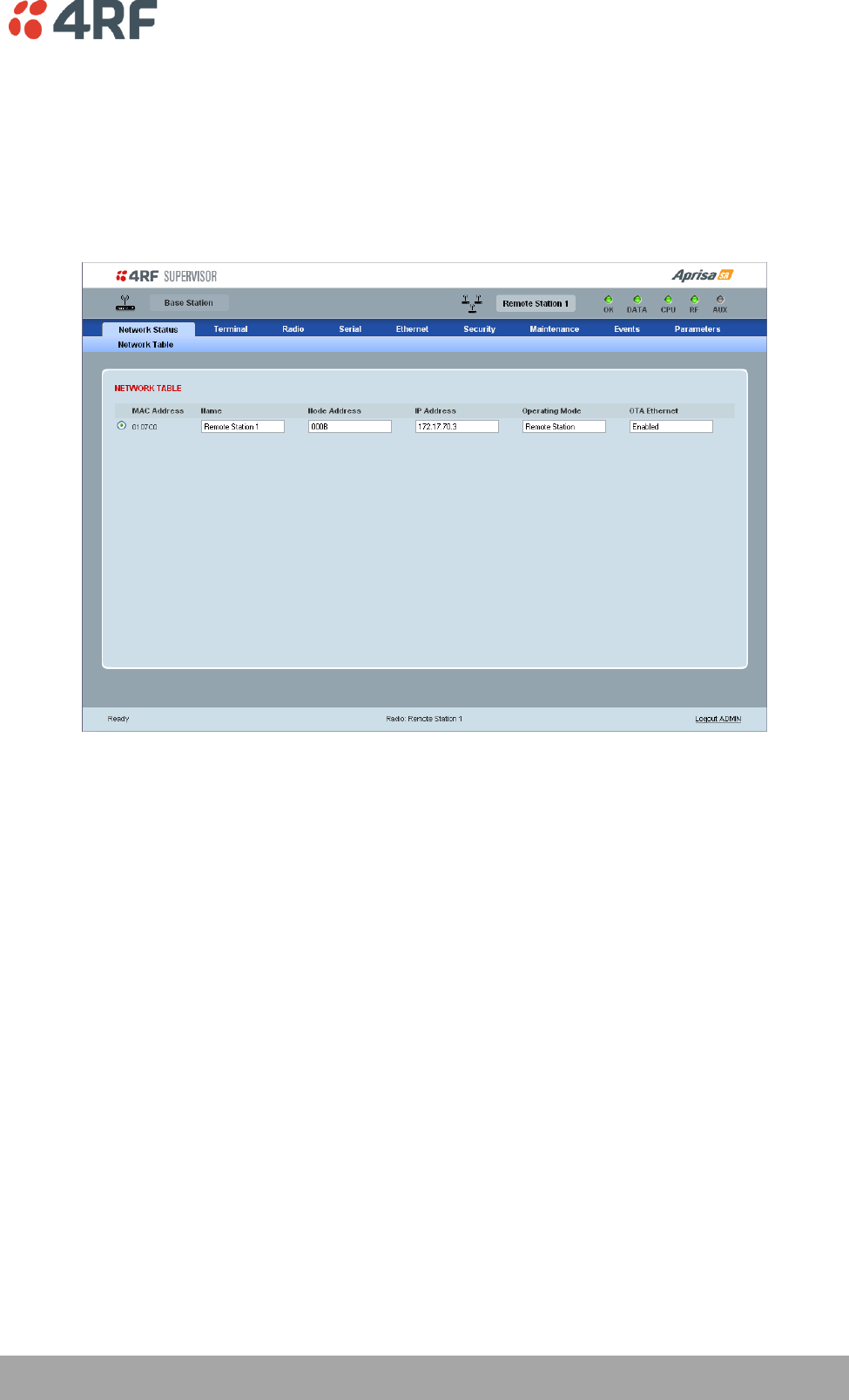
Managing the Radio | 69
Aprisa SR User Manual
SuperVisor Menu Items
The following SuperVisor menu item descriptions assume full access ‘Admin’ user privileges:
Network Status
Network Status > Network Table
NETWORK TABLE
This Network Table is only available when the local radio is the Base Station i.e. SuperVisor is logged into
the Base Station.
To manage a remote / Repeater Station with SuperVisor:
Click on the radio button of the required station. The remaining menu items then apply to the selected
radio.
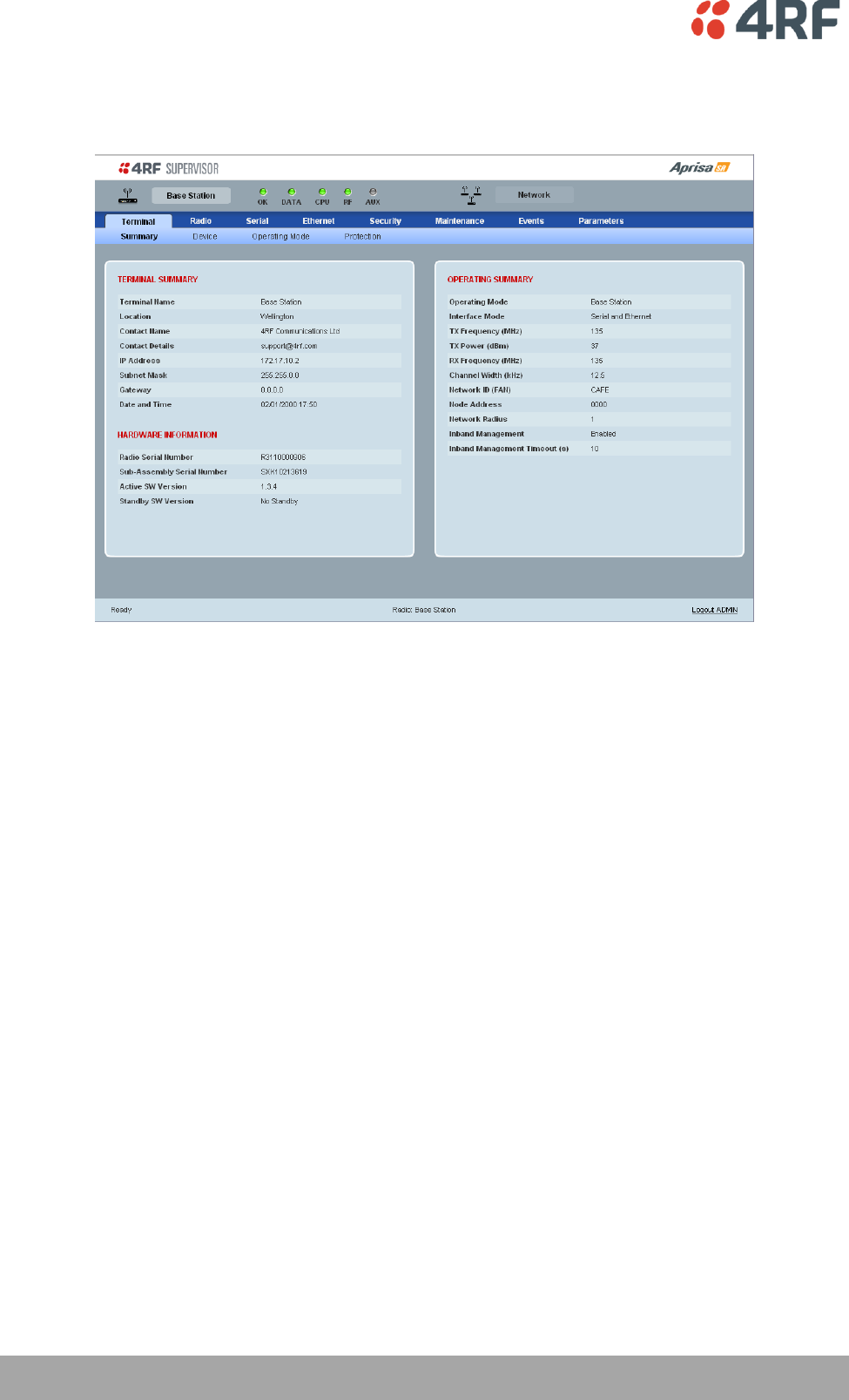
70 | Managing the Radio
Aprisa SR User Manual
Terminal
Terminal > Summary
TERMINAL SUMMARY
This page displays the current settings for the Terminal parameters.
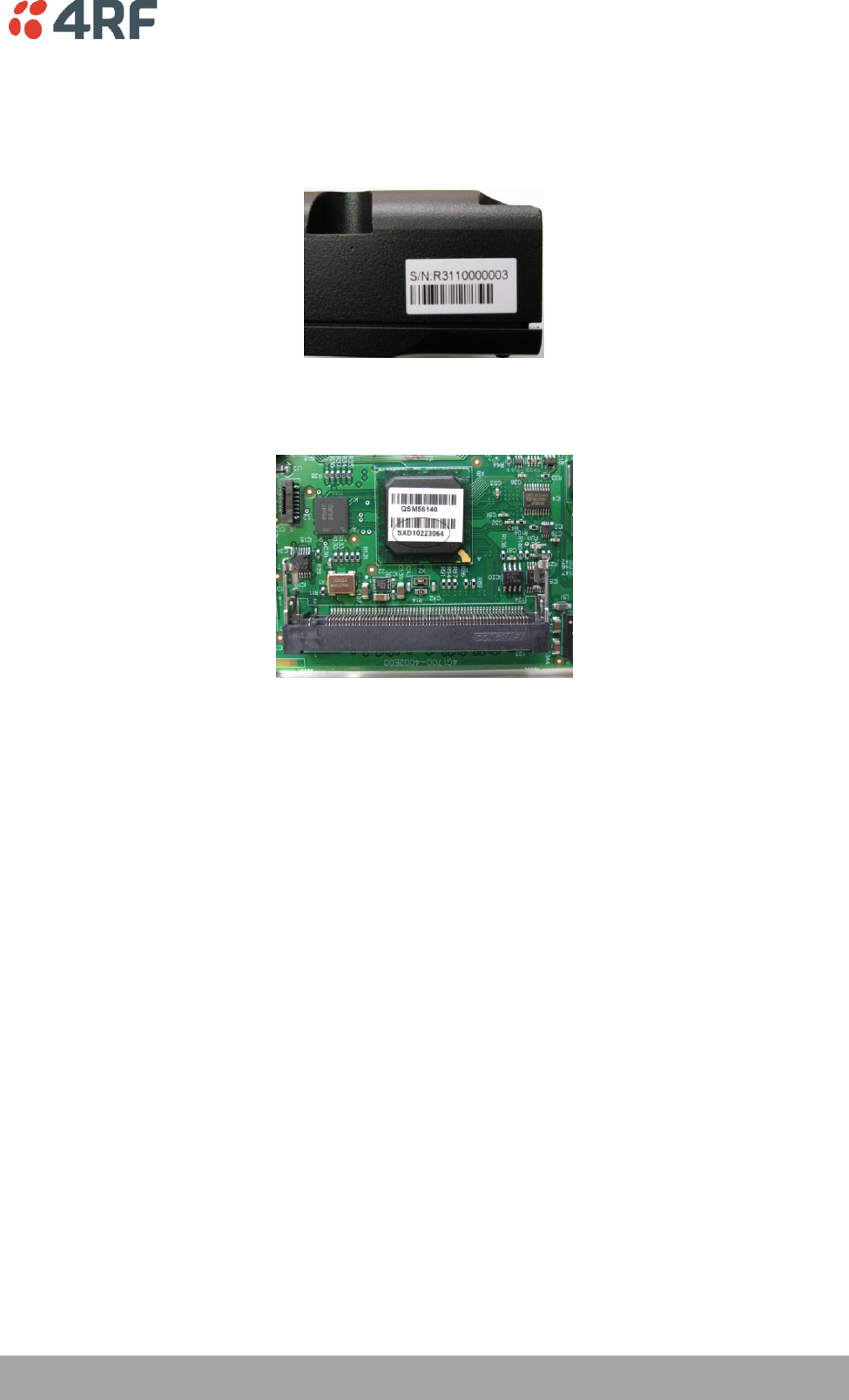
Managing the Radio | 71
Aprisa SR User Manual
HARDWARE INFORMATION
Radio Serial Number
This parameter displays the Serial Number of the radio (shown on the enclosure label).
Sub-Assembly Serial Number
This parameter displays the Serial Number of the printed circuit board assembly (shown on the PCB label).
Active SW Version
This parameter displays the version of the software currently operating the radio.
Standby SW Version
This parameter displays the version of the newly uploaded software.
If the Standby SW Version shown is ‘No Standby’, then no new software has been uploaded.
If the Standby SW Version shown is a version number e.g. 1.0.0, then new software has been uploaded in
to the Aprisa SR but has not been activated (see ‘Maintenance > Upgrade’ on page 114).

72 | Managing the Radio
Aprisa SR User Manual
OPERATING SUMMARY
Operating Mode
This parameter displays the current operating Mode i.e. if the radio is operating as a Base Station,
Repeater Station or Remote Station.
Interface Mode
This parameter displays the Interfaces available for traffic on the radio (see ‘Maintenance > Licence’ on
page 120).
TX Frequency (MHz)
This parameter displays the current Transmit Frequency in MHz.
TX Power (dBm)
This parameter displays the current Transmit Power in dBm.
RX Frequency (MHz)
This parameter displays the current Receive Frequency in MHz.
Channel Width (kHz)
This parameter displays the current Channel Width in kHz.
Network ID (Field Area Network)
This parameter is the network ID of this Base Station node and its Remote / Repeater Stations in the FAN.
The entry is four hex chars (not case sensitive).
Node Address
The Node Address of the Base Station is 0000.
If the Node Address shown is FFFE, this radio is a Remote Station or Repeater Station but has not been
registered with the Base Station.
The Base Station will automatically allocate a Node Address to all its registered Repeater Station and
Remote Station radios. This address can be between 0001 and F000.
Network Radius
This parameter displays the maximum number of hops in this network.
Inband Management
This parameter displays the status of the Inband Management option.
Inband Management Timeout (sec)
This parameter displays the number of seconds that the Base Station waits for a response from a Remote
or Repeater Station before aborting the Inband Management request.

Managing the Radio | 73
Aprisa SR User Manual
OPERATING SUMMARY
Protection Type
The Protection Type shows if this radio is part of an Aprisa SR Protected Station.
Active Unit
The Active Unit shows which radio is currently carrying traffic, the Primary radio or the Secondary radio.
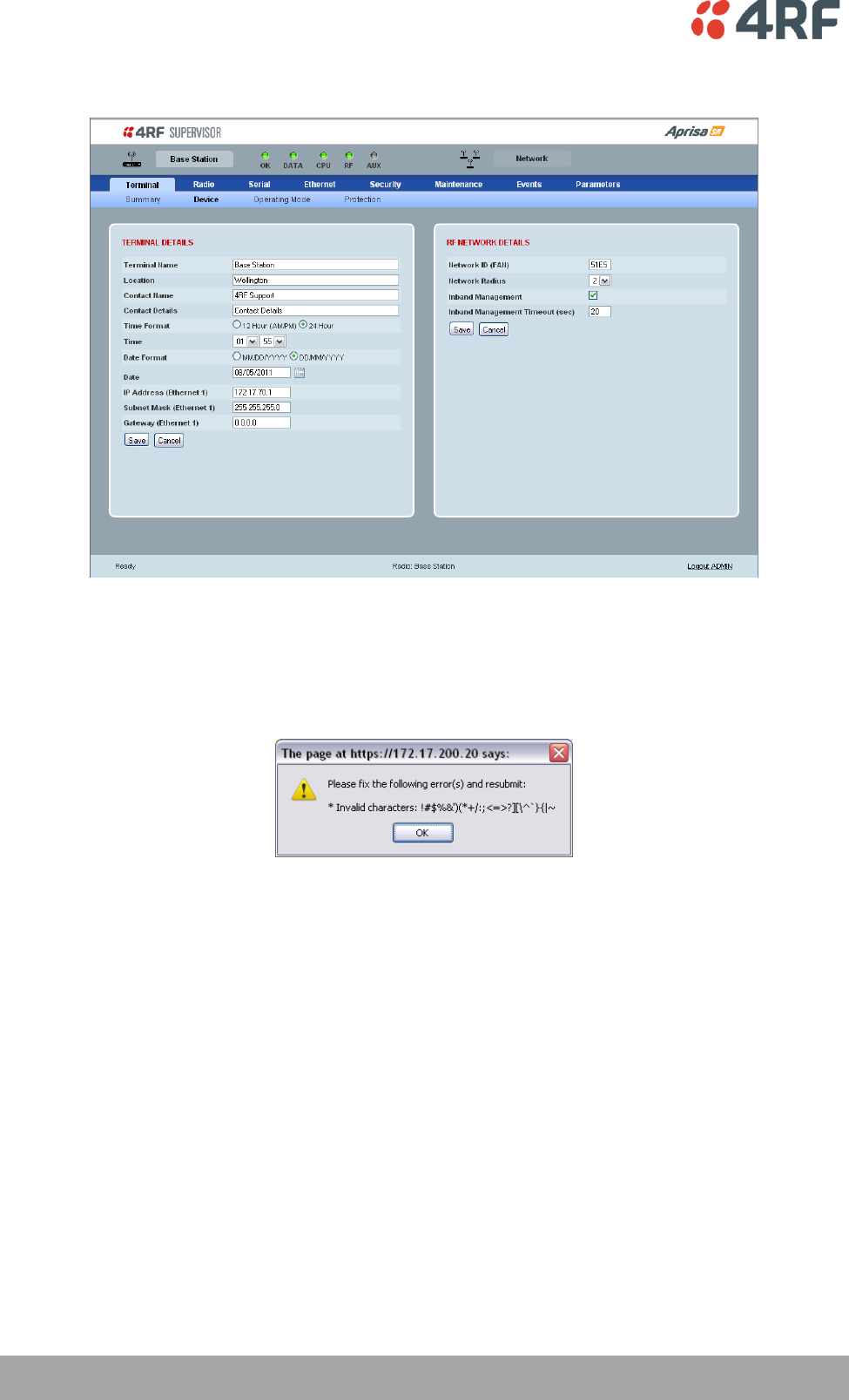
74 | Managing the Radio
Aprisa SR User Manual
Terminal > Device
TERMINAL DETAILS
The data entry in the next four fields can be up to 40 characters but cannot contain invalid characters. A
popup warns of the invalid characters:
1. Enter the Terminal Name.
2. Enter the Location of the radio.
3. Enter a Contact Name. The default value is ‘support@4RF.com’.
4. Enter the Contact Details.
5. Set the Time, Date Format and Date. This information is controlled from a software clock.
6. Set the static IP Address of the radio assigned by your site network administrator using the standard
format xxx.xxx.xxx.xxx. The default IP address is in the range 169.254.50.10.
7. Set the Subnet Mask of the radio using the standard format xxx.xxx.xxx.xxx. The default subnet mask
is 255.255.0.0.
8. Set the Gateway address of the radio, if required, using the standard format xxx.xxx.xxx. The default
Gateway is 0.0.0.0.

Managing the Radio | 75
Aprisa SR User Manual
RF NETWORK DETAILS
Network ID (FAN)
This parameter sets the network ID of this Base Station node and its Remote / Repeater Stations in the
FAN. The entry is four hexadecimal chars (not case sensitive). The default setting is CAFE.
Network Radius
This parameter sets the maximum number of hops in this network e.g. if the Network Radius is set to 2, a
message from that node will only pass 2 hops before it is blocked. The default setting is 1.
All stations in the FAN should be set to the same value.
Inband Management
This parameter sets the Inband Management option.
If the Inband Management option is enabled, SuperVisor operating on a Base Station can also manage all
the Remote / Repeater Stations in the FAN.
Inband Management Timeout (sec)
This parameter sets the Inband Management timeout period. This determines the time the Base Station
waits for a response from a Remote or Repeater Station before aborting the Inband Management request.
The default setting is 10 seconds.
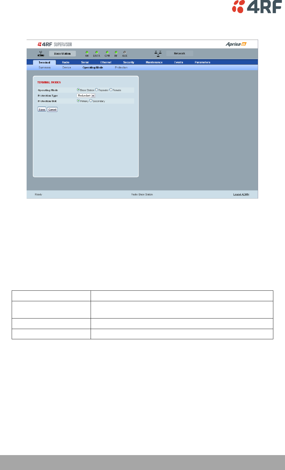
76 | Managing the Radio
Aprisa SR User Manual
Terminal > Operating Mode
TERMINAL MODES
Operating Mode
The Operating Mode can be set to Base Station, Repeater Station or Remote Station. The default setting is
Remote Station.
Protection Type
The Protection Type defines if a radio is a stand-alone radio or part of an Aprisa SR Protected Station. The
default setting is None.
Protection Type
Function
None
The SR radio is stand alone radio (not part of an Aprisa SR
Protected Station).
Redundant
The SR radio is part of an Aprisa SR Protected Station
Serial Data Driven Switching
The SR radio is part of an Aprisa SR Data Driven Protected Station
Protection Unit
The Protection Unit defines if this radio is the primary radio or secondary radio in a Protected Station.
One radio in the Protected Station is set to Primary and the other radio to Secondary.
It is recommended that radio A (the left radio) be configured as the Primary and that radio B (the right
radio) be configured as the Secondary. The default setting is Primary.
This menu item is only applicable if this radio is part of an Aprisa SR Protected Station.
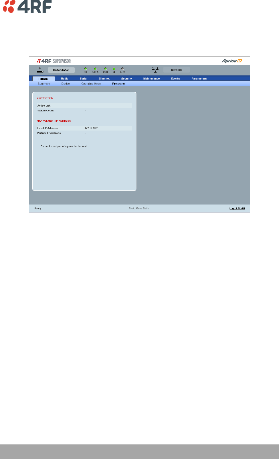
Managing the Radio | 77
Aprisa SR User Manual
Terminal > Protection
This menu item is only applicable if this radio is part of an Aprisa SR Protected Station.
PROTECTION
Active Unit
The Active Unit shows which radio is currently carrying traffic, the Primary radio or the Secondary radio.
Switch Count
The Switch Count shows the number of protections switch-overs since the last radio reboot (volatile).
MANAGEMENT IP ADDRESS
Local IP Address
The Local IP Address shows the IP address of this radio.
Partner IP Address
The Partner IP Address shows the IP address of the other radio in the Protected Station.
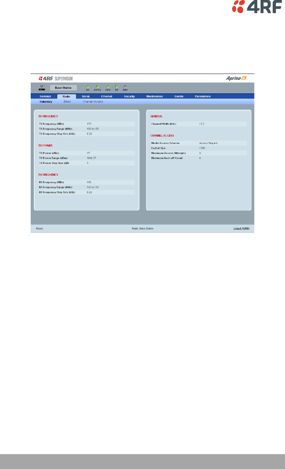
78 | Managing the Radio
Aprisa SR User Manual
Radio
Radio > Summary
This page displays the current settings for the Radio parameters.
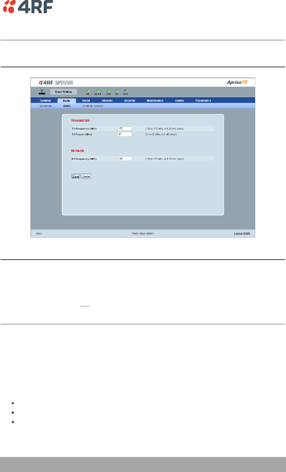
Managing the Radio | 79
Aprisa SR User Manual
Radio > Basic
Note: Transmit frequency, transmit power and channel size would normally be defined by a local
regulatory body and licensed to a particular user. Refer to your site license details when setting these
fields.
RF SETTINGS
Important:
1. Changing the Remote / Repeater Station frequencies will disable all management communication to the
Remote / Repeater Stations but then by changing the Base Station to match the Remote / Repeater
Stations, the radio links will be restored as will the management communication.
2. Enter the TX frequency and the RX frequency and then click ‘Save’. This is to prevent remote
management communication from being lost before both frequencies have been changed in the Remote
Stations.
TX and RX Frequencies.
The TX and RX frequencies entered must be within the frequency tuning range of the product frequency
band and will be automatically resolved to the synthesizer step size for the frequency band e.g. an ETSI
400 MHz band frequency entry of 458,004,000 Hz will be changed to 458,006,250 Hz (see ‘Frequency
Bands’ on page 148). The default setting is 400,000,000 Hz.
The TX and RX frequencies can be single frequency ½ duplex or dual frequency ½ duplex. Dual frequency
½ duplex is often used for reasons of:
Channel Planning.
Network Efficiencies.
Regulatory rules.
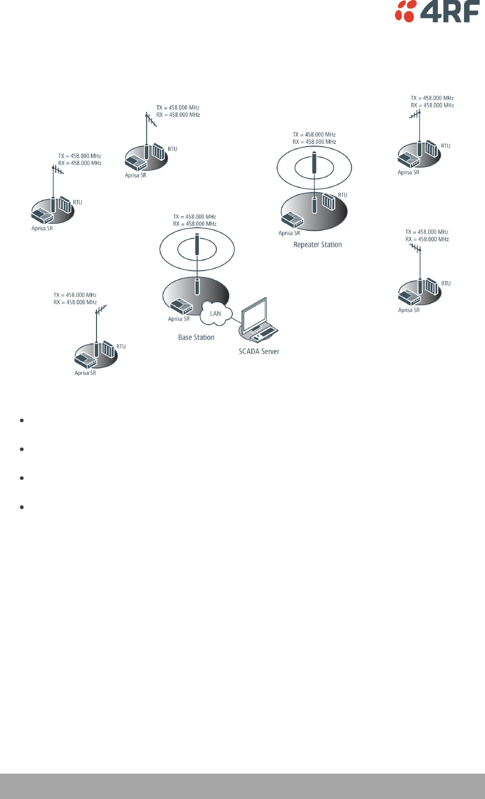
80 | Managing the Radio
Aprisa SR User Manual
Single Frequency Operation
The TX and RX frequencies of the Base Station, Repeater Station and all the Remote Stations are on the
same frequency.
To change the TX and RX frequencies:
Change the TX and RX frequencies of the Remote Stations operating from the Repeater Station to
the new frequency. The radio links to these Remote Stations will fail.
Change the TX and RX frequencies of the Repeater Station operating from the Base Station to the
new frequency. The radio links to the Repeater Station and its Remote Stations will fail.
Change the TX and RX frequencies of the Remote Stations operating from the Base Station to the
new frequency. The radio links to these Remote Stations will fail.
Change the TX and RX frequencies of the Base Station to the new frequency. The radio links to all
stations will restore.
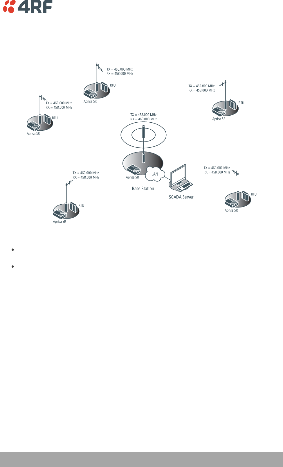
Managing the Radio | 81
Aprisa SR User Manual
Dual Frequency No Repeater
The TX frequency of all the Remote Stations matches the RX frequency of the Base Station.
The RX frequency of all the Remote Stations matches the TX frequency of the Base Station.
To change the TX and RX frequencies:
For all the Remote Stations, change the RX frequency to frequency A and the TX frequency to
frequency B. The radio links to the Remote Stations will fail.
For the Base Station, change the TX frequency to frequency A and the RX frequency to frequency
B. The radio links to the Remote Stations will restore.
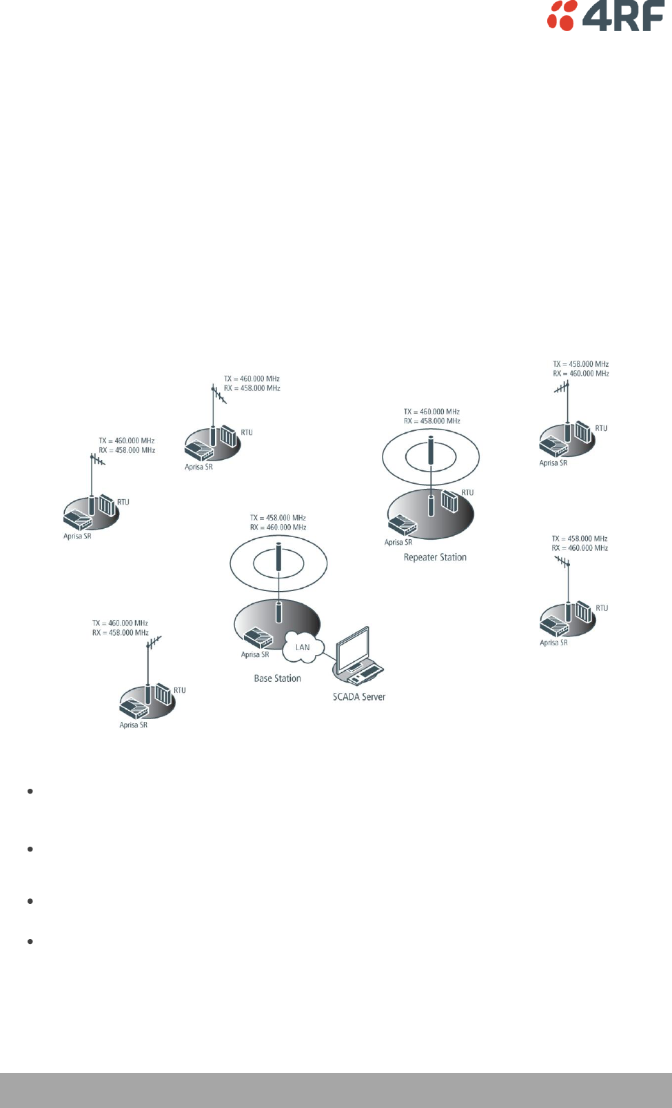
82 | Managing the Radio
Aprisa SR User Manual
Dual Frequency with Repeater
The TX frequency of the Remote Stations associated with the Base Station matches the RX frequency of
the Base Station.
The TX frequency of the Repeater Station associated with the Base Station matches the RX frequency of
the Base Station.
The TX frequency of the Remote Stations associated with the Repeater Station matches the RX frequency
of the Repeater Station.
The RX frequency of the Remote Stations associated with the Base Station matches the TX frequency of
the Base Station.
The RX frequency of the Repeater Station associated with the Base Station matches the TX frequency of
the Base Station.
The RX frequency of the Remote Stations associated with the Repeater Station matches the TX frequency
of the Repeater Station.
To change the TX and RX frequencies:
For all the Remote Stations operating from the Repeater Station, change the RX frequency to
frequency A and the TX frequency to frequency B. The radio links to these Remote Stations will
fail.
For the Repeater Station, change the TX frequency to frequency A and the RX frequency to
frequency B.
For the Base Station, change the RX frequency to frequency A and the TX frequency to frequency
B. The radio links to the Remote Stations operating from the Repeater Station will restore.
For all the Remote Stations operating from the Base Station, change the TX frequency to frequency
A and the RX frequency to frequency B.

Managing the Radio | 83
Aprisa SR User Manual
Transmit power
The transmitter power is the power measured at the antenna output port when transmitting. The
transmitter power has a direct impact on the radio power consumption (see ‘Power Consumption’ on page
153) and ‘Save’ the change.
The default setting is +37 dBm.
Note: The Aprisa SR transmitter contains power amplifier protection which allows the antenna to be
disconnected from the antenna port without product damage.
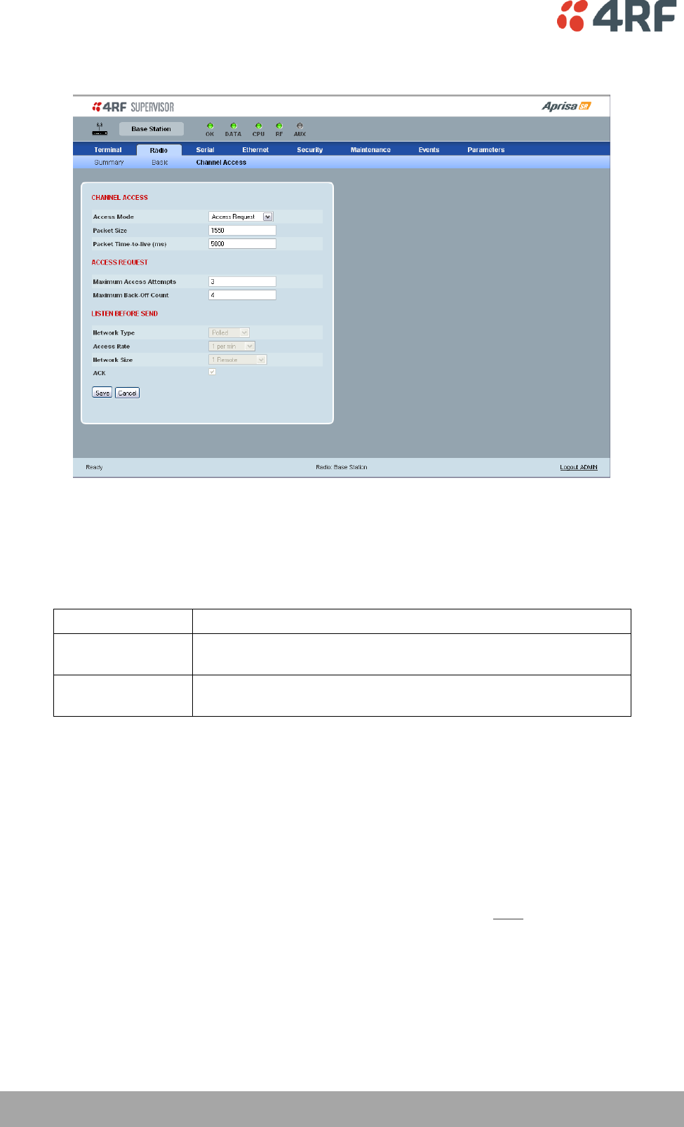
84 | Managing the Radio
Aprisa SR User Manual
Radio > Channel Access
CHANNEL ACCESS
Access Mode
This parameter sets the Media Access Control (MAC) used by the radio for over the air communication.
Access Mode
Function
Access Request
This mode is a general purpose access method for high and low
load networks
Listen Before Send
This mode is optimised for low load networks and repeated
networks
The default setting is Access Request.
Packet Size (Bytes)
This parameter sets the maximum over-the-air packet size in bytes. A smaller maximum Packet Size is
beneficial when many Remote Stations or Repeater Stations are trying to access the channel. The default
setting is 1550 Bytes.
As radios dispatched from the factory have a Packet Size set to the maximum value of 1550 bytes, if a new
radio is installed in an existing Field Access Network (FAN), the Packet Size must be changed to ensure it
is the same value for all radios in the FAN. The new radio will not register an existing FAN if the Packet
Size is not the same as the other radios in the FAN.
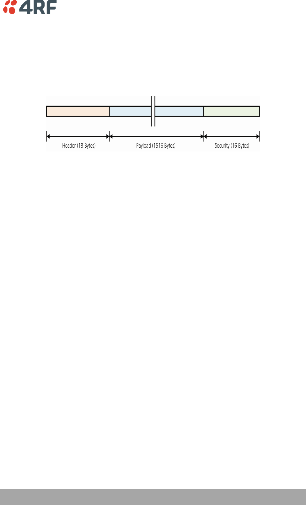
Managing the Radio | 85
Aprisa SR User Manual
Note that this includes the wireless protocol header (18 to 20 Bytes) and security payload (0 to 16 Bytes).
The length of the security header depends on the level of security selected.
An example wireless protocol frame structure is illustrated below. This uses maximum security of
16 Bytes. The length of the header varies depending on whether the user data must be segmented. User
data will be segmented if it is larger than the wireless packet payload length. In this case, this limit is
213 Bytes. If the user data packet is larger than this, then the header increases to 20 Bytes to account for
the transport of the required segmentation and reassembly data.
Note that when the security setting is 0, the maximum user data transfer over-the-air is 1516 Bytes.
When encryption is enabled, the entire packet of user data (payload) is encrypted. If authentication is
being used, the security frame will be added (up to 16 bytes). The wireless protocol header is then added
which is proprietary to the Aprisa SR. This is not encrypted.
Packet Time to Live (ms)
This parameter sets the time a packet is allowed to live in the system before being dropped if it cannot be
transmitted over the air.
The default setting is 5000 ms.
ACCESS REQUEST
Maximum Access Attempts
This parameter sets the maximum number of attempts the MAC will try to acquire the channel for the
packet to be transmitted before it is dropped.
The default setting is 3.
Maximum Back-Off Count
This parameter sets the random back-off period before the MAC tries to acquire the channel to transmit a
packet.
The default setting is 4.
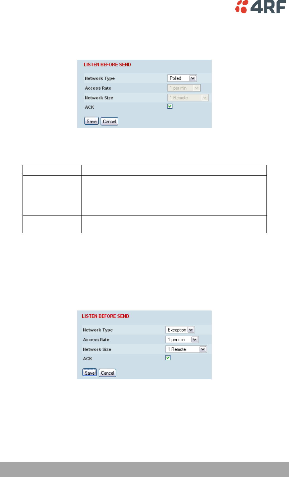
86 | Managing the Radio
Aprisa SR User Manual
LISTEN BEFORE SEND
When the Access Mode is set for Listen Before Send, the Listen Before Send parameters can be set:
Network Type
This parameter sets the operating mechanism used in the FAN:
Network Type
Function
Polled
The SR radio network is part of a polling system e.g. if a SCADA
master station is set up to periodically poll remote terminal units
(RTUs).
Channel access for data traffic in this case is completely controlled
by the external SCADA master.
Exception
The Base Station and all remote and Repeater Stations can send
traffic asynchronously.
The default setting is Polled.
All Channel Access parameters are calculated and set automatically for the network topology and the size
of packet that is being transmitted. This improves channel utilization if there are variable size packets on
the network.
When the Network Type is set for Exception, the Access Rate and Network Size parameters can be set:
Access Rate
This parameter defines the rate at which the channel is accessed by remote or Repeater Stations. It is an
approximation of the traffic rates on the FAN.
The default setting is 1 per min.

Managing the Radio | 87
Aprisa SR User Manual
Network Size
This parameter defines the number of scope of the FAN e.g. 2-10 Remotes. This enables the Channel
Access parameters to be optimized for the network topology.
The default setting is 1 remote.
ACK
This parameter determines if unicast requests from the Remote Station are acknowledged by the Base
Station. Receiving acknowledgments increases reliability of transport but reduces available channel
capacity so if application has the capability to handle lost or duplicate messages, the ACK should be
disabled.
When enabled, the transmitter requests an ACK to ensure that the transmission has been successful. If the
transmitter does not receive an ACK, then random back-offs are used to reschedule the next transmission.
The default setting is enabled.
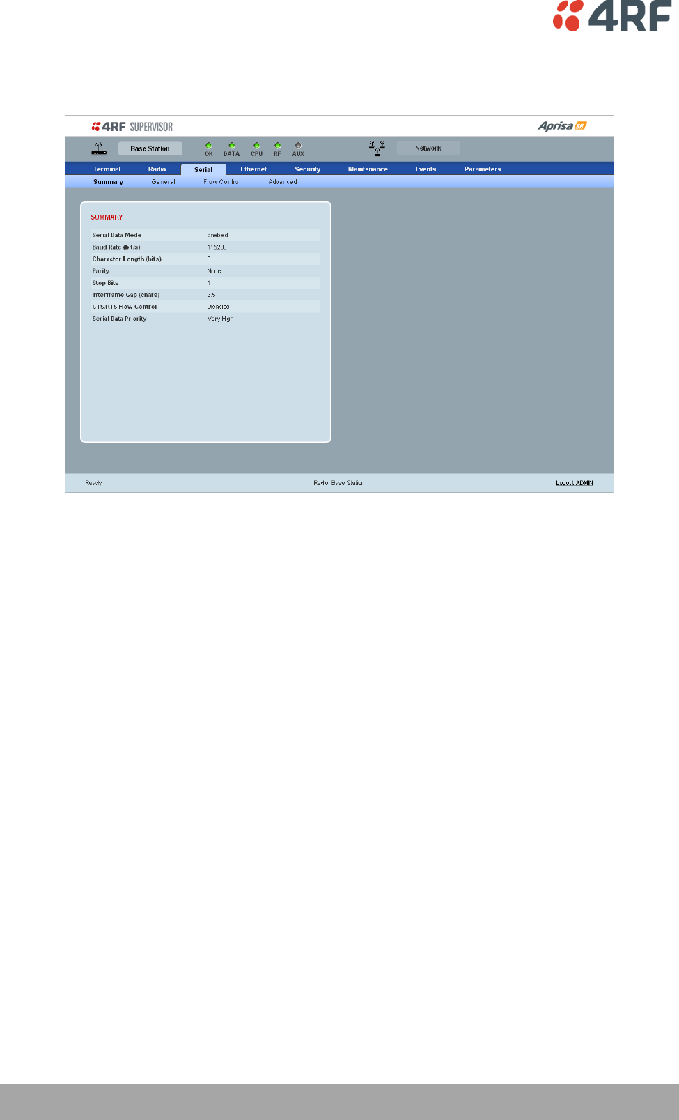
88 | Managing the Radio
Aprisa SR User Manual
Serial
Serial > Summary
SUMMARY
This page displays the current settings for the Serial interface parameters.
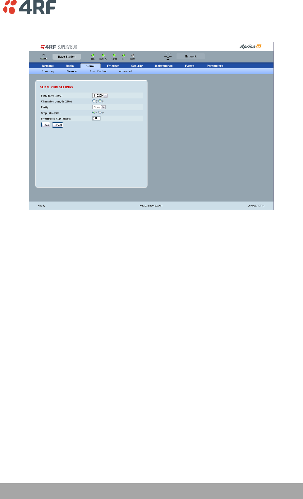
Managing the Radio | 89
Aprisa SR User Manual
Serial > General
SERIAL PORT SETTINGS
Baud Rate (bit/s)
The baud rate can be set to 300, 1200, 2400, 4800, 9600, 19200, 38400, 57600 or 115200 bit/s. The
default setting is 115200 bit/s.
Character Length (bits)
The character length can be set to 7 or 8 bits. The default setting is 8 bits.
Parity
The parity can be set to Even, Odd or None. The default setting is None.
Stop Bits (bits)
The stop bits can be set to 1 or 2 bits. The default setting is 1 bit.
Inter-Frame Gap (chars)
This parameter defines the gap between successive serial data frames. It is used to delimit the serial data
to define the end of a packet. The Inter-Frame Gap limits are 0.5 to 16 chars. The default setting is 3.5
chars.
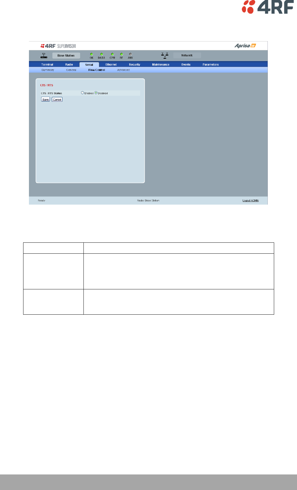
90 | Managing the Radio
Aprisa SR User Manual
Serial > Flow Control
CTS / RTS Status
The CTS / RTS Status can be set to enabled or disabled. The default setting is Disabled.
CTS / RTS Status
Function
Enabled
CTS / RTS hardware flow control between the DTE and the Aprisa
SR radio port (DCE) is enabled.
If the Aprisa SR buffer is full, the CTS goes OFF.
In the case of radio link failure the signal goes to OFF (-ve) state.
Disabled
The Aprisa SR radio port (DCE) CTS is in a permanent ON (+ve)
state.
This does not go to OFF if the radio link fails.
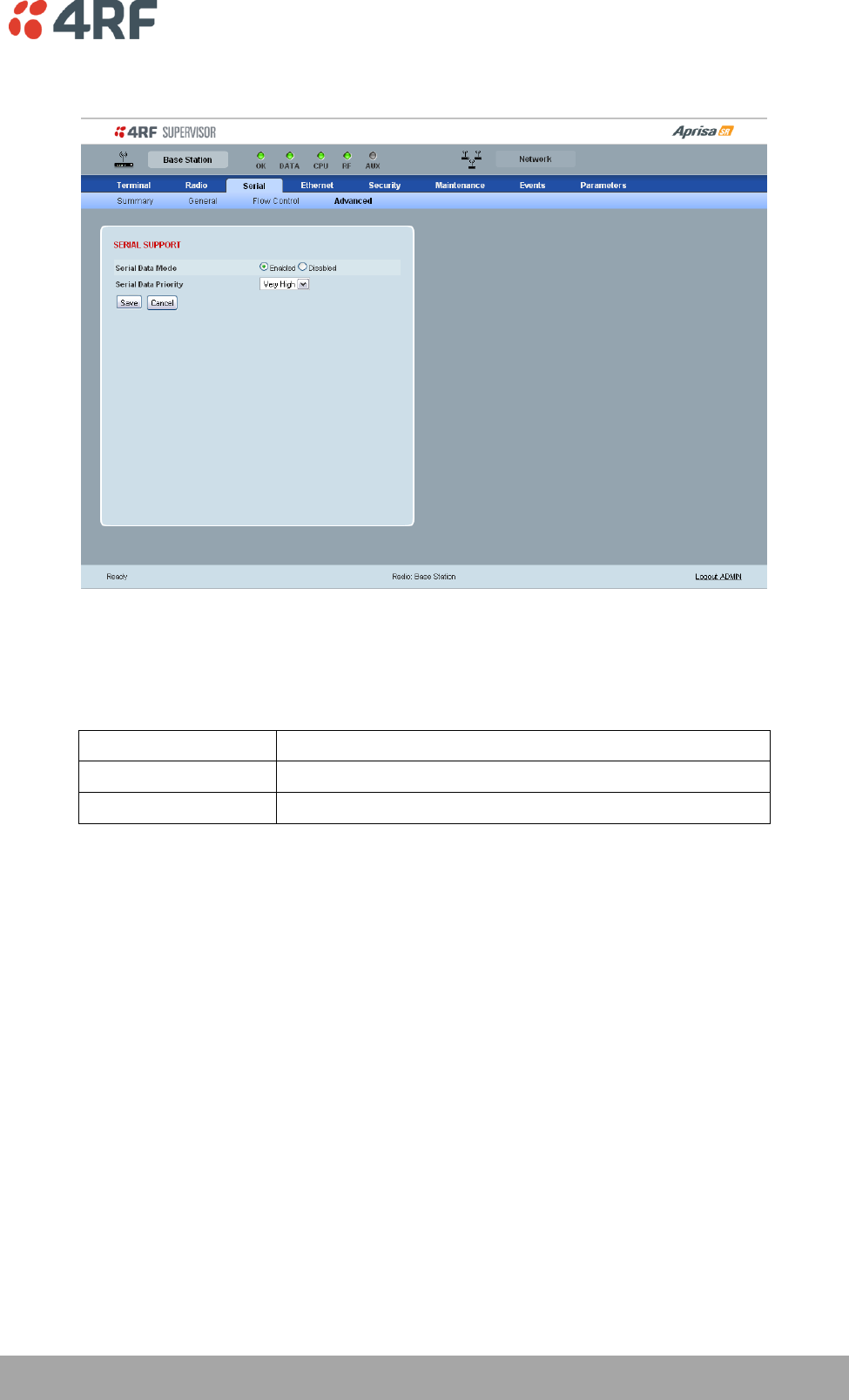
Managing the Radio | 91
Aprisa SR User Manual
Serial > Advanced
SERIAL SUPPORT
Serial Data Mode
The Serial Data Mode can be set to Enabled or Disabled. The default setting is Enabled.
Serial Data Mode
Function
Enabled
Enables serial data communication over the radio link.
Disabled
Disables serial data communication over the radio link.
Serial Data Priority
The Serial Data Priority controls the priority of the serial traffic relative to the Ethernet traffic. If equal
priority is required to Ethernet traffic, this setting must be the same as the Ethernet Data Priority setting.
The serial data priority can be set to Very High, High, Medium and Low. The default setting is Very High.
A queuing system is used to prioritize traffic from the serial and Ethernet interfaces for over the air
transmission. A weighting may be given to each data type and this is used to schedule the next
transmission over the air e.g. if there are pending data packets in multiple buffers but serial data has a
higher weighting it will be transmitted first. The serial buffer is 20 serial packets (1 packet can be up to
512 bytes).
There are four priority queues in the Aprisa SR: Very High, High, Medium and Low. Data is added to one of
these queues depending on the priority setting. Data leaves the queues from highest priority to lowest:
the Very High queue is emptied first, followed by High then Medium and finally Low.
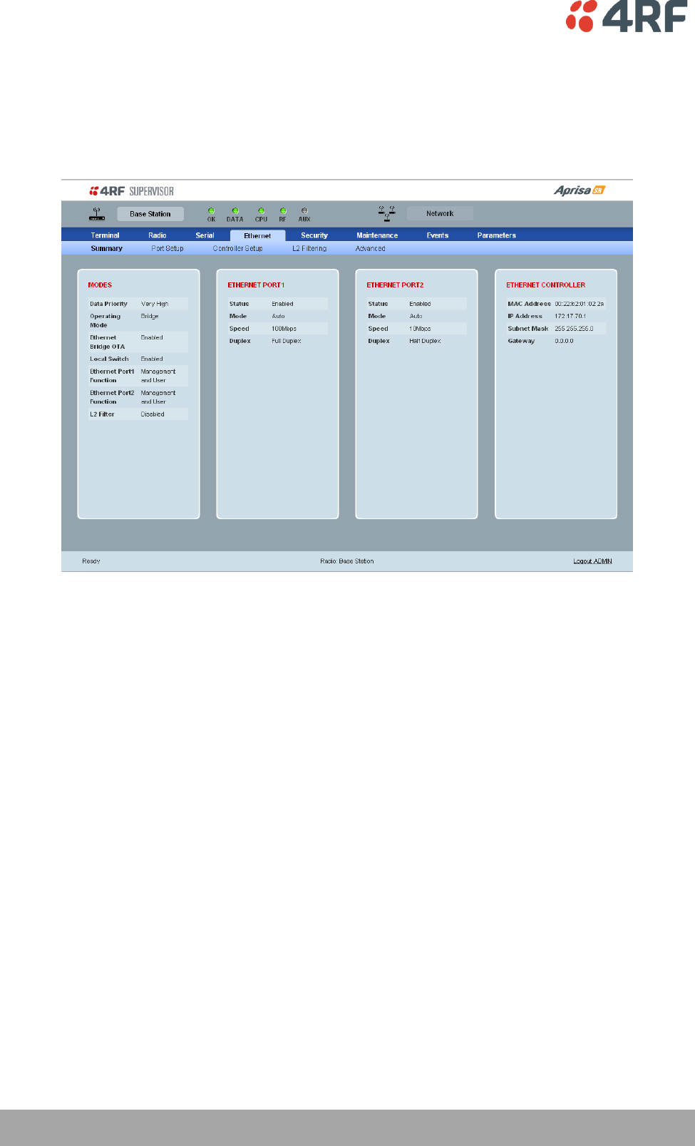
92 | Managing the Radio
Aprisa SR User Manual
Ethernet
Ethernet > Summary
This page displays the current settings for the Ethernet interface parameters.
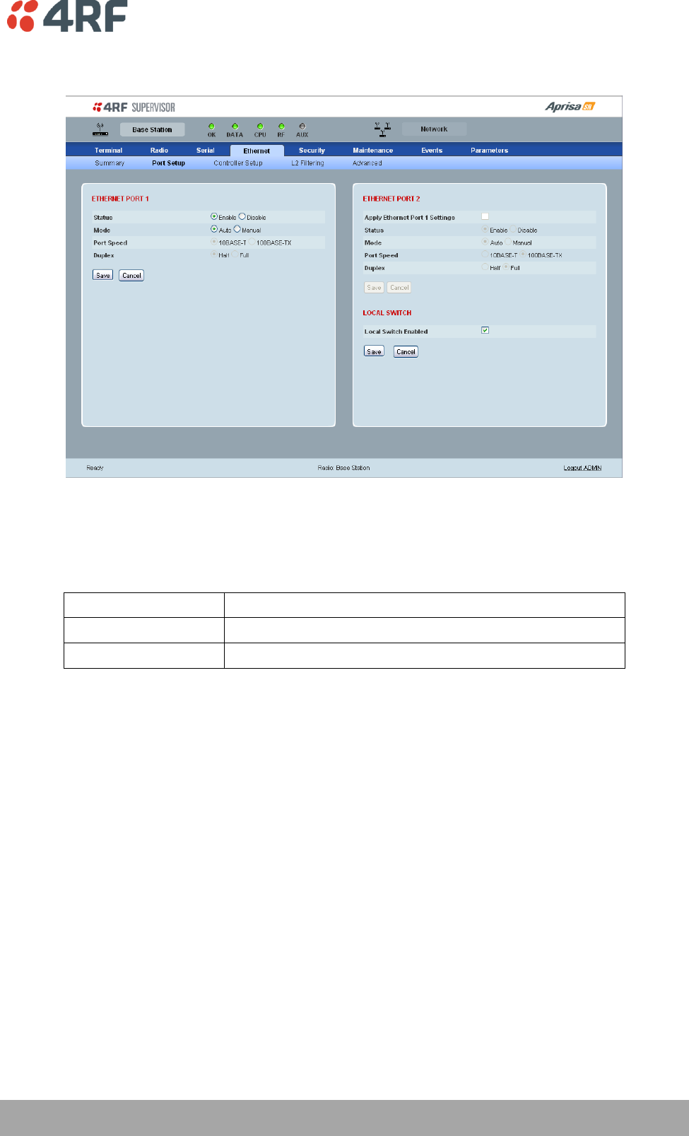
Managing the Radio | 93
Aprisa SR User Manual
Ethernet > Port Setup
ETHERNET PORT 1
Status
The Ethernet port status can be set to enabled or disabled. The default setting is enabled.
Ethernet Data Mode
Function
Enabled
Enables Ethernet data communication over the radio link.
Disabled
Disables Ethernet data communication over the radio link.
Mode
The Ethernet port mode can be set to Auto or Manual. The default setting is Auto.
Auto provides auto selection of Ethernet Port Speed and Ethernet Duplex.
If Ethernet port mode of Manual is selected, the Ethernet Port Speed and Ethernet Duplex can be set.
94 | Managing the Radio
Aprisa SR User Manual
ETHERNET PORT 2
If this radio is part of a Protected Station, these parameters cannot be changed.
Apply Ethernet Port 1 Settings option (Ethernet Port 2 pane only)
If you require Ethernet Port 2 settings to be the same as Ethernet Port 1, tick the checkbox.
LOCAL SWITCH
Local Switch option (Ethernet Port 2 pane only)
This parameter sets the Local Switch option. The default setting is Enabled.
Local Switch
Function
Enabled
Ethernet traffic is switched locally between the two
Ethernet ports and communicated over the radio link.
Disabled
Ethernet traffic is only communicated over the radio link.
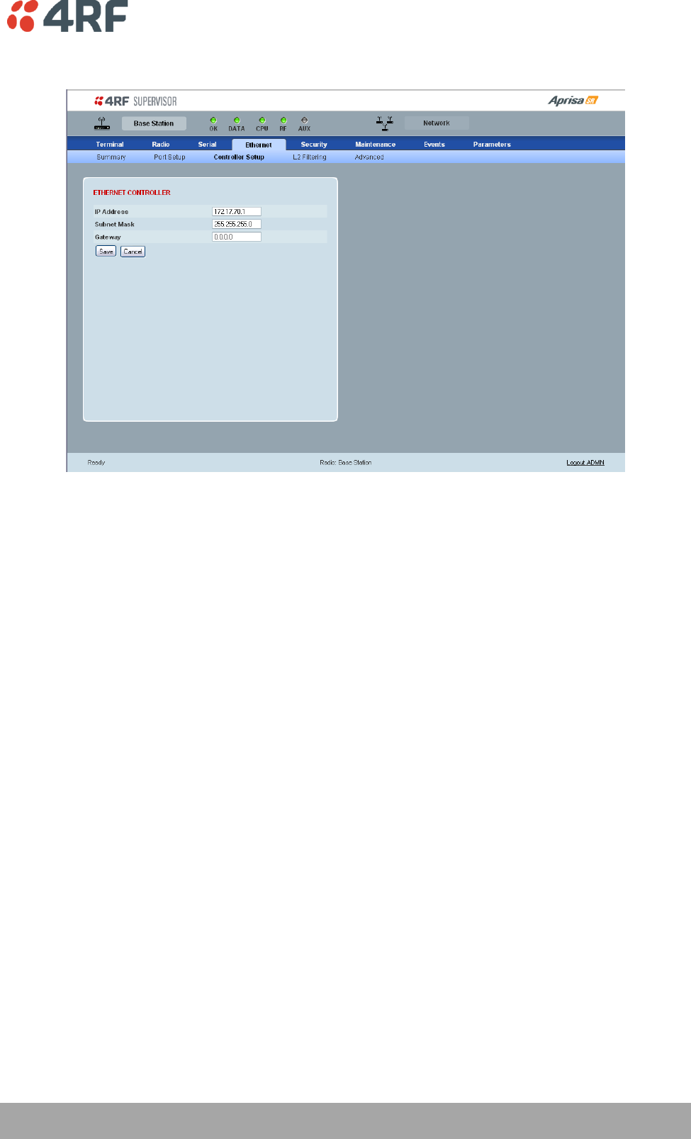
Managing the Radio | 95
Aprisa SR User Manual
Ethernet > Controller Setup
ETHERNET CONTROLLER
IP Address
Set the static IP Address of the radio assigned by your site network administrator using the standard
format xxx.xxx.xxx.xxx. The default IP address is in the range 169.254.50.10.
Subnet Mask
Set the Subnet Mask of the radio using the standard format xxx.xxx.xxx.xxx. The default subnet mask is
255.255.0.0.
Gateway
Set the Gateway address of the radio, if required, using the standard format xxx.xxx.xxx. The default
Gateway is 0.0.0.0.
These settings are the same as setting the parameters in ‘Terminal > Device’ on page 74.
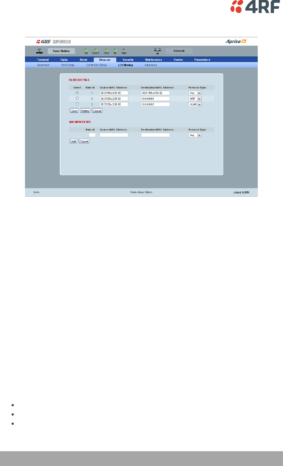
96 | Managing the Radio
Aprisa SR User Manual
Ethernet > L2 Filtering
FILTER DETAILS
L2 Filtering provides the ability to filter radio link traffic based on specified Layer 2 MAC addresses.
Traffic originating from specified Source MAC Addresses destined for specified Destination MAC Addresses
that meets the protocol type criteria will be transmitted over the radio link.
Traffic that does not meet the filtering criteria will not be transmitted over the radio link.
If the Source MAC Address is set to ‘FF:FF:FF:FF:FF:FF’, traffic will be accepted from any source MAC
address.
If the Destination MAC Address is set to ‘FF:FF:FF:FF:FF:FF’, traffic will be delivered to any destination
MAC address.
Protocol Type
This parameter sets the Ethernet Type accepted ARP, VLAN, IPv4, IPv6 or ANY type.
Example:
In the screen shot, the rules are configured in the Base Station which controls the radio link traffic from
Base Station to remote / Repeater Stations.
Traffic from a device with the MAC address 00:01:50:c2:01:00 is forwarded over the radio link if it meets
the criteria:
Rule 1 If the Ethernet Type is ARP going to any destination MAC address or
Rule 2 If the Ethernet Type is ANY and the destination MAC address is 01:00:50:c2:01:02 or
Rule 3 If the Ethernet Type is VLAN tagged packets going to any destination MAC address

Managing the Radio | 97
Aprisa SR User Manual
Special L2 Filtering Rules:
Unicast Only Traffic
This L2 filtering allows for Unicast only traffic and drop broadcast and multicast traffic. This filtering is
achieved by adding the two rules:
Rule
Source
MAC Address
Destination
MAC Address
Protocol Type
Allow ARPS
FF:FF:FF:FF:FF:FF
FF:FF:FF:FF:FF:FF
ARP
Allow Unicasts from ANY source
FF:FF:FF:FF:FF:FF
FE:FF:FF:FF:FF:FF
ANY
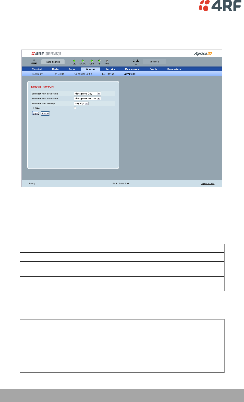
98 | Managing the Radio
Aprisa SR User Manual
Ethernet > Advanced
This screen is only available if the Ethernet traffic option has been licenced (see ‘Maintenance >
Licence’ on page 120).
ETHERNET SUPPORT
There must always be an Ethernet port available for management, so both Ethernet ports cannot be set to
User Only.
Ethernet Port 1 Function
This parameter sets the use for the Ethernet port 1. The default setting is Management Only.
Ethernet Port Function
Function
Management Only
The Ethernet port is only used for management of the FAN.
Management and User
The Ethernet port is used for management of the FAN and
User traffic over the radio link.
User Only
The Ethernet port is only used for User traffic over the radio
link.
Ethernet Port 2 Function
This parameter sets the use for the Ethernet port 2. The default setting is User Only.
Ethernet Port Function
Function
Management Only
The Ethernet port is only used for management of the FAN.
Management and User
The Ethernet port is used for management of the FAN and
User traffic over the radio link.
User Only
The Ethernet port is only used for User traffic over the radio
link. This option is not available if this radio is part of a
Protected Station.

Managing the Radio | 99
Aprisa SR User Manual
Ethernet Data Priority
The Ethernet Data Priority controls the priority of the Ethernet traffic relative to the serial traffic. If
equal priority is required to serial traffic, this setting must be the same as the Serial Data Priority setting
The Ethernet Data Priority can be set to Very High, High, Medium and Low. The default setting is Very
High.
A queuing system is used to prioritize traffic from the serial and Ethernet interfaces for over the air
transmission. A weighting may be given to each data type and this is used to schedule the next
transmission over the air e.g. if there are pending data packets in multiple buffers but serial data has a
higher weighting it will be transmitted first. The Ethernet buffer is 10 Ethernet packets (1 packet can be
up to Ethernet MTU, 1500 bytes).
There are four priority queues in the Aprisa SR: Very High, High, Medium and Low. Data is added to one of
these queues depending on the priority setting. Data leaves the queues from highest priority to lowest:
the Very High queue is emptied first, followed by High then Medium and finally Low.
L2 Filter
This parameter enables / disables L2 Filtering. The default setting is disabled.
If L2 Filtering is enabled, the filters defined in Ethernet > L2 Filtering become active.
If L2 Filtering is disabled, the filters defined in Ethernet > L2 Filtering have no effect.
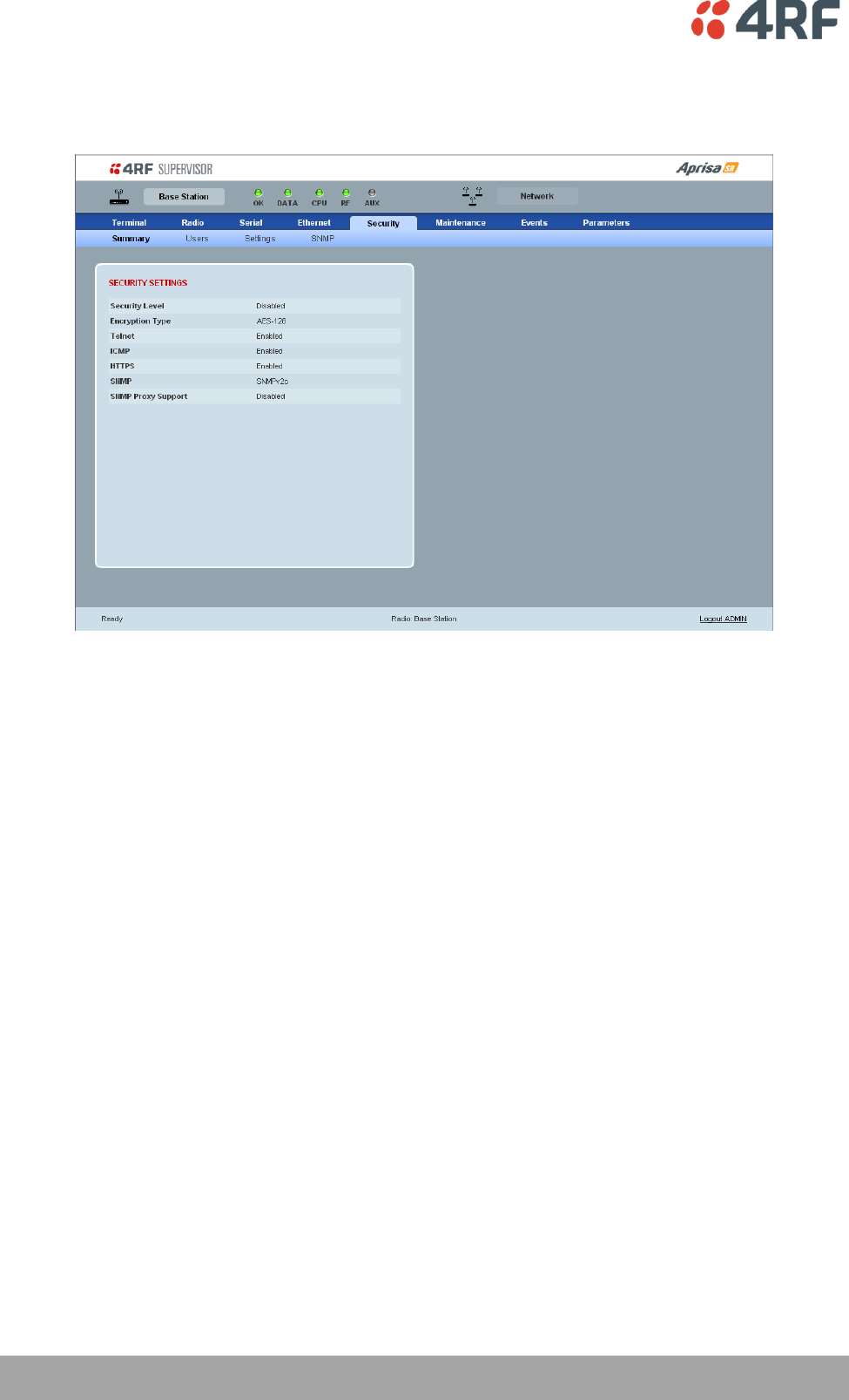
100 | Managing the Radio
Aprisa SR User Manual
Security
Security > Summary
SECURITY SETTINGS
This page displays the current settings for the Security parameters.
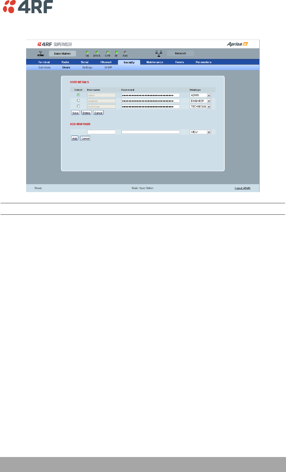
Managing the Radio | 101
Aprisa SR User Manual
Security > Users
Note: You must login with 'admin' privileges to add, disable, delete a user or change a password.
USER DETAILS
Shows a list of the current users setup in the radio.
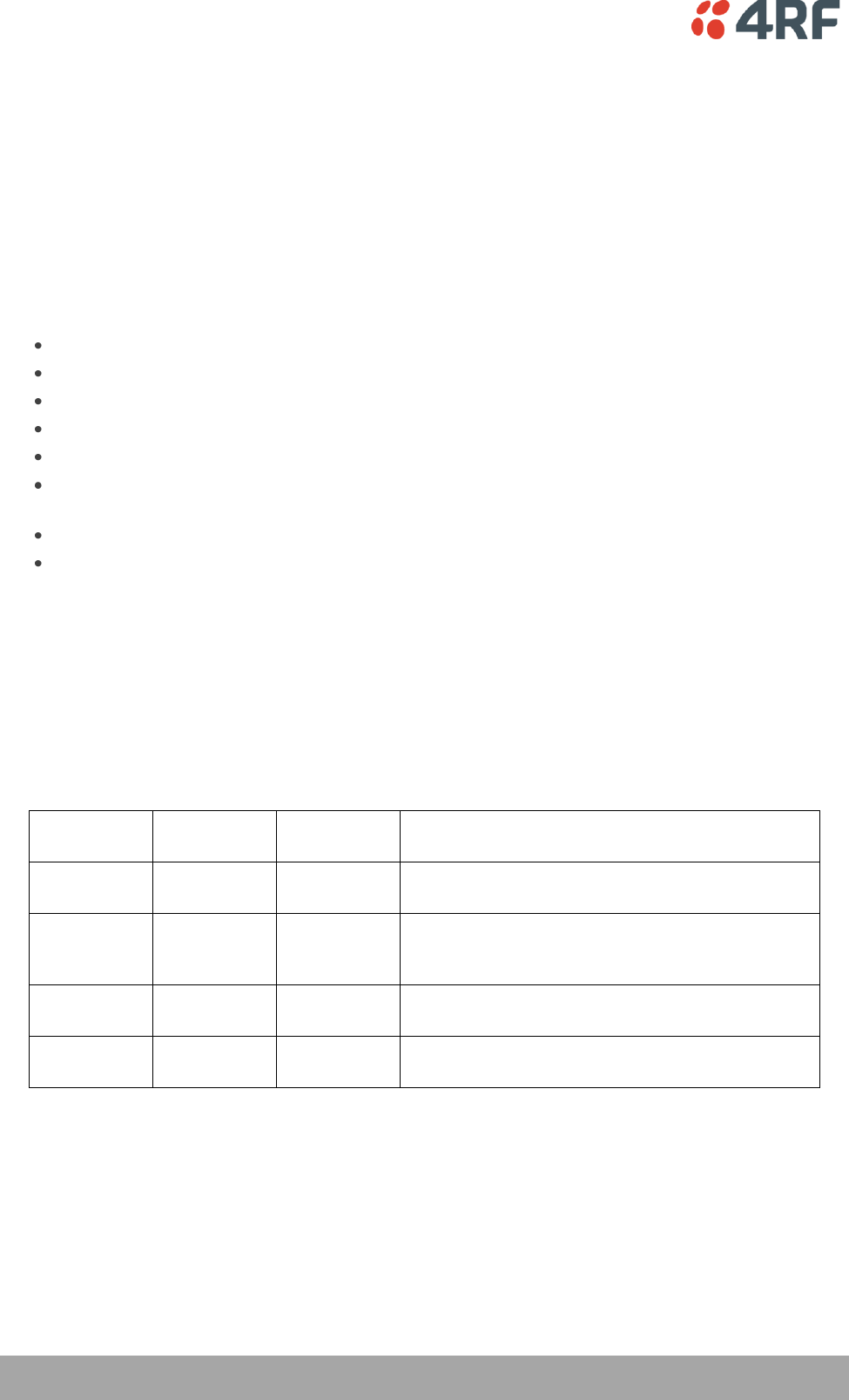
102 | Managing the Radio
Aprisa SR User Manual
ADD NEW USER
1. Enter the Username.
A username can be up to 32 characters but cannot contain back slashes, forward slashes, spaces, tabs,
single or double quotes. Usernames are case sensitive.
2. Enter the Password.
A password can be up to 32 characters but cannot contain back slashes, forward slashes, spaces, tabs,
single or double quotes. Passwords are case sensitive.
Good password policy:
contains at least eight characters, and
contains at least one upper case letter, and
contains at least one lower case letter, and
contains at least one digit or another character such as !@#$%^&(){}[]<>... , and
is not a term in a familiar language or jargon, and
is not identical to or derived from the accompanying account name, from personal characteristics
or from information from one’s family/social circle, and
is easy to remember, for instance by means of a key sentence, and
can be typed in fluently.
3. Select the User Privileges
There are four pre-defined User Privilege settings to allocate access rights to users. These user privileges
have associated default usernames and passwords of the same name.
The default login is ‘admin’.
This login has full access to all radio parameters including the ability to add and change users. There can
only be a maximum of two usernames with admin privileges and the last username with admin privileges
cannot be deleted.
User
Privilege
Default
Username
Default
Password
User Privileges
View
view
view
Users in this group can only view the summary
pages.
Technician
technician
technician
Users in this group can view and edit parameters
except Security > Users, Security > Settings and
Advanced settings.
Engineer
engineer
engineer
Users in this group can view and edit parameters
except Security > Users.
Admin
admin
admin
Users in this group can view and edit all
parameters.
See ‘SuperVisor Menu Access’ on page 68 for the list of SuperVisor menu items versus user privileges.
4. Click ‘Add’

Managing the Radio | 103
Aprisa SR User Manual
To delete a user:
1. Select Terminal Settings > Security > Users
2. Click on the Select button for the user you wish to delete.
3. Click ‘Delete
To change a Password:
1. Select Terminal Settings > Security > Users
2. Click on the Select button for the user you wish to change the Password.
3. Enter the Password.
A password can be up to 32 characters but cannot contain back slashes, forward slashes, spaces, tabs,
single or double quotes.
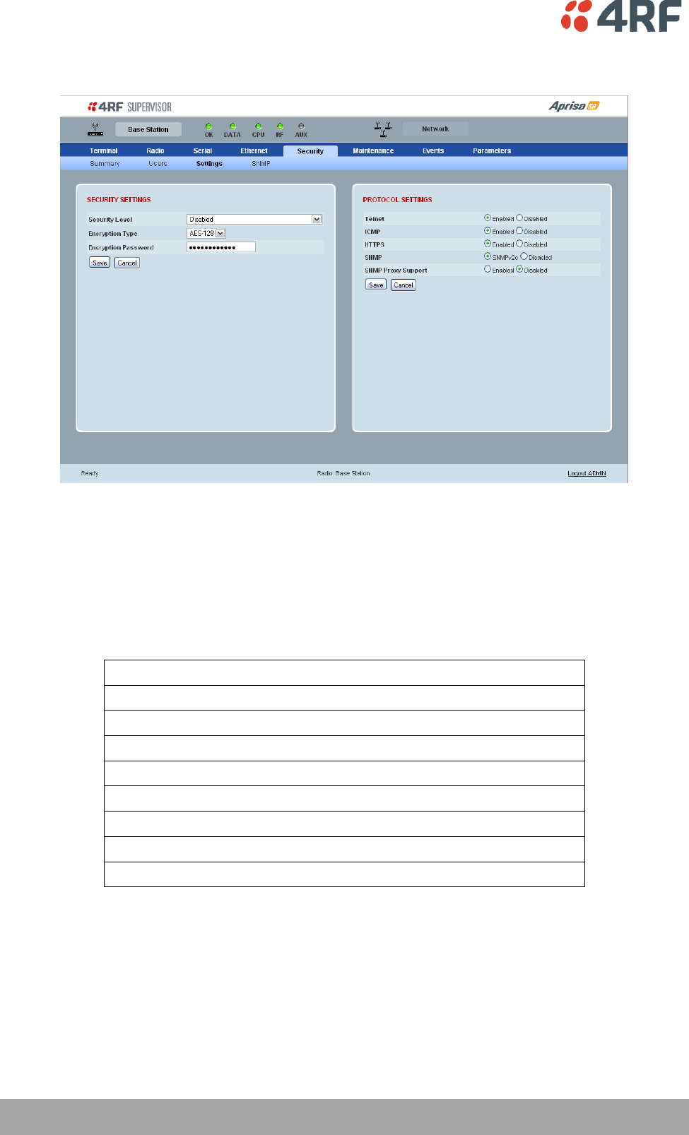
104 | Managing the Radio
Aprisa SR User Manual
Security > Settings
SECURITY SETTINGS
The Security Level, Encryption Type and Encryption Password must be the same on all radios in the FAN.
Security Level
This parameter sets the security level to one of the values in the following table. The default setting is
disabled.
Security Level
disabled (No encryption and no Message Authentication Code)
AES Encryption + CCM Authentication 128 bit
AES Encryption + CCM Authentication 64 bit
AES Encryption + CCM Authentication 32 bit
AES Encryption only
CCM Authentication 128 bit
CCM Authentication 64 bit
CCM Authentication 32 bit
Encryption Type
This parameter sets the Encryption Type to AES128, AES192 or AES256. The default setting is AES128.
The higher the encryption type the better the security.

Managing the Radio | 105
Aprisa SR User Manual
Encryption Password
This parameter sets the Encryption password. This is used to create the AES encryption key.
Good password policy:
contains at least eight characters, and
contains at least one upper case letter, and
contains at least one lower case letter, and
contains at least one digit or another character such as !@#$%^&(){}[]<>... , and
is not a term in a familiar language or jargon, and
is not identical to or derived from the accompanying account name, from personal characteristics
or from information from one’s family/social circle, and
is easy to remember, for instance by means of a key sentence, and
can be typed in fluently.
PROTOCOL SETTINGS
Telnet option
This parameter option determines if you can manage the radio via a Telnet session. The default setting is
disabled.
ICMP option (Internet Control Message Protocol)
This parameter option determines whether the radio will respond to a ping. The default setting is
enabled.
HTTPS option
This parameter option determines if you can manage the radio via a HTTPS session (via a Browser). The
default setting is enabled.
SNMP option
This parameter option determines if you can manage the radio via SNMP. The default setting is SNMPv2c.
SNMP Proxy Support
This parameter option enables an SNMP proxy server in the Base Station. This proxy server reduces the
radio link traffic during SNMP communication to Remote / Repeater Stations. This option applies to the
Base Station only. The default setting is disabled.
This option can also be used if the radio has Serial Only interfaces.

106 | Managing the Radio
Aprisa SR User Manual
SNMP Manager Setup
The SNMP manager community strings must be setup to access the Base Station and Remote / Repeater
Stations.
To access the Base Station, a community string must be setup on the SNMP manager the same as the
community string setup on the radio (see ‘Security > SNMP’ on page 107).
To access the Remote / Repeater Stations, the community strings must be setup on the SNMP manager in
the format:
ccccccccc:bbbbbb
Where:
ccccccccc is the community string of the Base Station
and
bbbbbb is the last 3 bytes of the remote station MAC address (see ‘Network Status > Network Table’
on page 69).
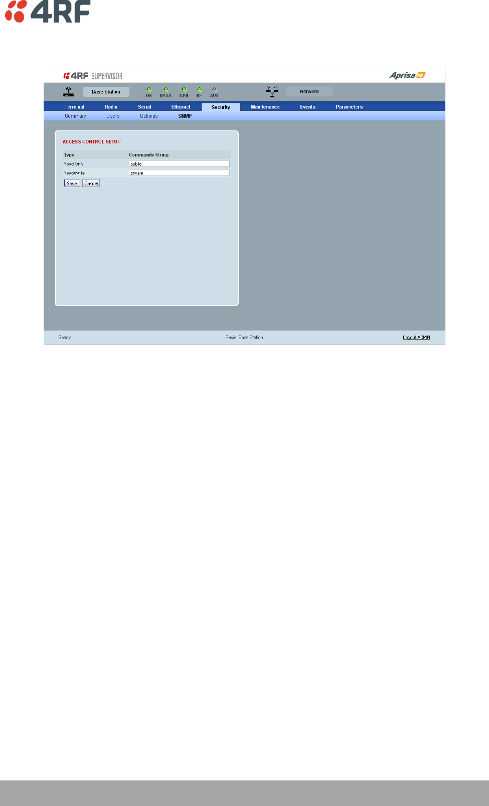
Managing the Radio | 107
Aprisa SR User Manual
Security > SNMP
In addition to web-based management (SuperVisor), the FAN can also be managed using the Simple
Network Management Protocol (SNMP). MIB files are supplied, and these can be used by a dedicated SNMP
Manager, such as Castle Rock's SNMPc, to access most of the radio's configurable parameters.
For communication between the SNMP manager and the radio, Access Controls and Community strings
must be set up as described in the following sections.
A SNMP Community String is used to protect against unauthorized access (similar to a password). The
SNMP agent (radio or SNMP manager) will check the community string before performing the task
requested in the SNMP message.
ACCESS CONTROL SETUP
A SNMP Access Control is the IP address of the radio used by an SNMP manager or any other SNMP device
to access the radio. The Aprisa SR allows access to the radio from any IP address.
Read Only
The default Read Only community string is public.
Read Write
The default ReadWrite community string is private.
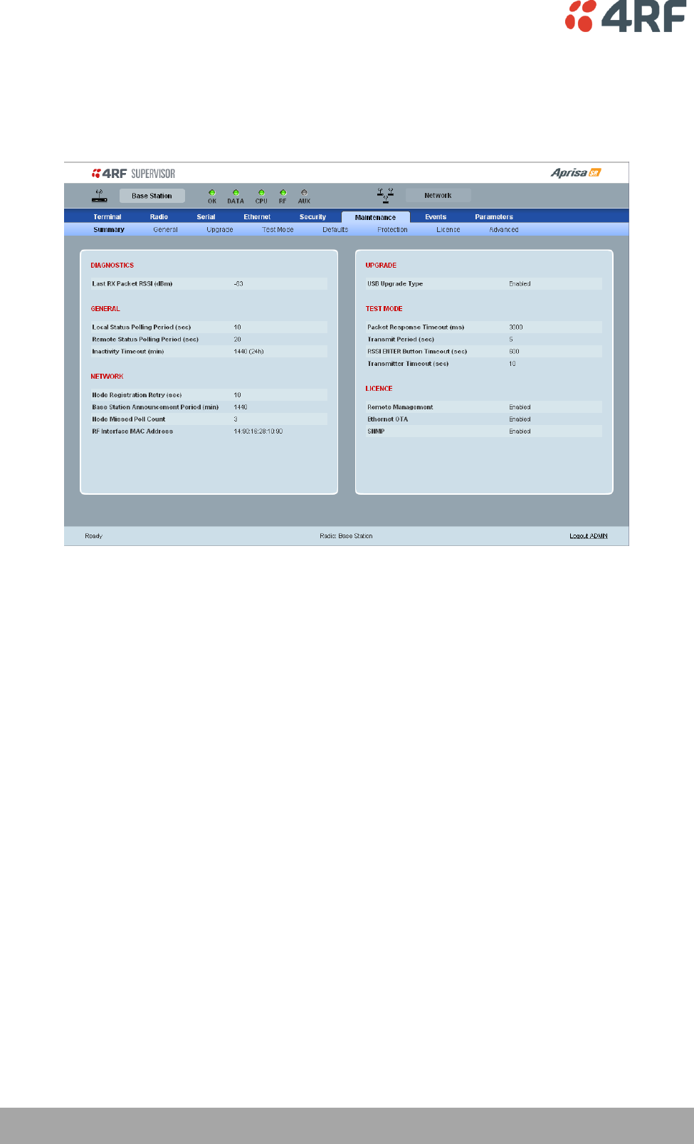
108 | Managing the Radio
Aprisa SR User Manual
Maintenance
Maintenance > Summary
This page displays the current settings for the Maintenance parameters.
DIAGNOSTICS
Last RX Packet RSSI (dBm)
This parameter displays the receiver RSSI reading taken from the last data packet received.
GENERAL
Local Status Polling Period (sec)
This parameter displays the rate at which SuperVisor refreshes the Local Radio alarm LED states and RSSI
value.
Remote Status Polling Period (sec)
This parameter displays the rate at which SuperVisor refreshes the Remote Radio alarm LED states and
RSSI value.
Inactivity Timeout (min)
This parameter displays the period of user inactivity before SuperVisor automatically logs out of the radio.

Managing the Radio | 109
Aprisa SR User Manual
NETWORK
Node Registration Retry (sec)
This parameter displays the Base Station poll time at startup or the Remote / Repeater Station time
between retries until registered.
Base Station Announcement Period (min)
This parameter displays the period between Base Station polls post startup. The default setting is 1440
minutes.
Node Missed Poll Count
This parameter displays the number of times the Base Station attempts to poll the FAN at startup or if a
duplicate IP is detected when a Remote / Repeater Station is replaced.
RF Interface MAC address
This parameter displays the RF Interface MAC address when the radio is part of a Protected Station.
UPGRADE
USB Upgrade
This parameter displays the USB upgrade status.
TEST MODE
Packet Response Timeout (ms)
This parameter displays the time Test Mode waits for a response from the Base Station before it times out
and retries.
Transmit Period (sec)
This parameter displays the time between Test Mode requests to the Base Station.
Response Timeout (ms)
This parameter sets the time Test Mode waits for a response from the Base Station before it times out and
retries. The default setting is 3000 ms.
RSSI Enter Button Timeout (sec)
This parameter displays the Test Mode timeout period. The radio will automatically exit Test Mode after
the Timeout period.
Transmitter Timeout (sec)
This parameter displays the transmitter Test Mode timeout period. The radio will automatically exit the
transmitter Test Mode after the Timeout period.

110 | Managing the Radio
Aprisa SR User Manual
LICENCE
Remote Management
This parameter displays if Remote Management is enabled or disabled.
Ethernet OTA (over the air)
This parameter displays if Ethernet traffic is enabled or disabled.
SNMP Management
This parameter displays if SNMP management is enabled or disabled.
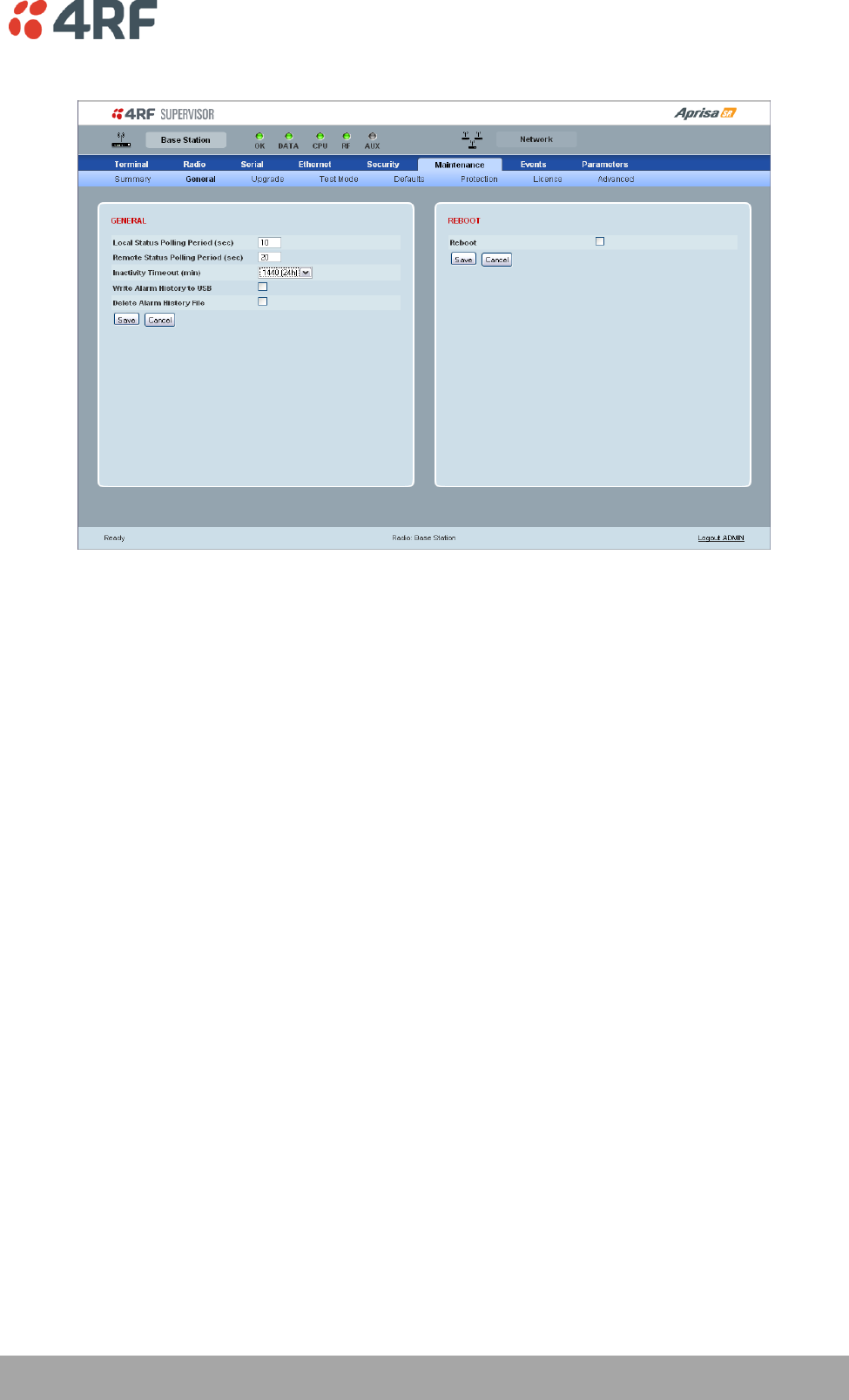
Managing the Radio | 111
Aprisa SR User Manual
Maintenance > General
GENERAL
Local Status Polling Period (sec)
This parameter sets the rate at which SuperVisor refreshes the Local Radio alarm LED states and RSSI
value. The default setting is 10 seconds.
Remote Status Polling Period (sec)
This parameter sets the rate at which SuperVisor refreshes the Remote Radio alarm LED states and RSSI
value. To avoid problems when managing Aprisa SR Networks, ensure that the Remote Polling Period is set
to be longer than the Inband Management Timeout (set on page 74). The default setting is 20 seconds.
Inactivity Timeout (min)
This parameter sets the period of user inactivity before SuperVisor automatically logs out of the radio. The
default setting is 15 minutes.
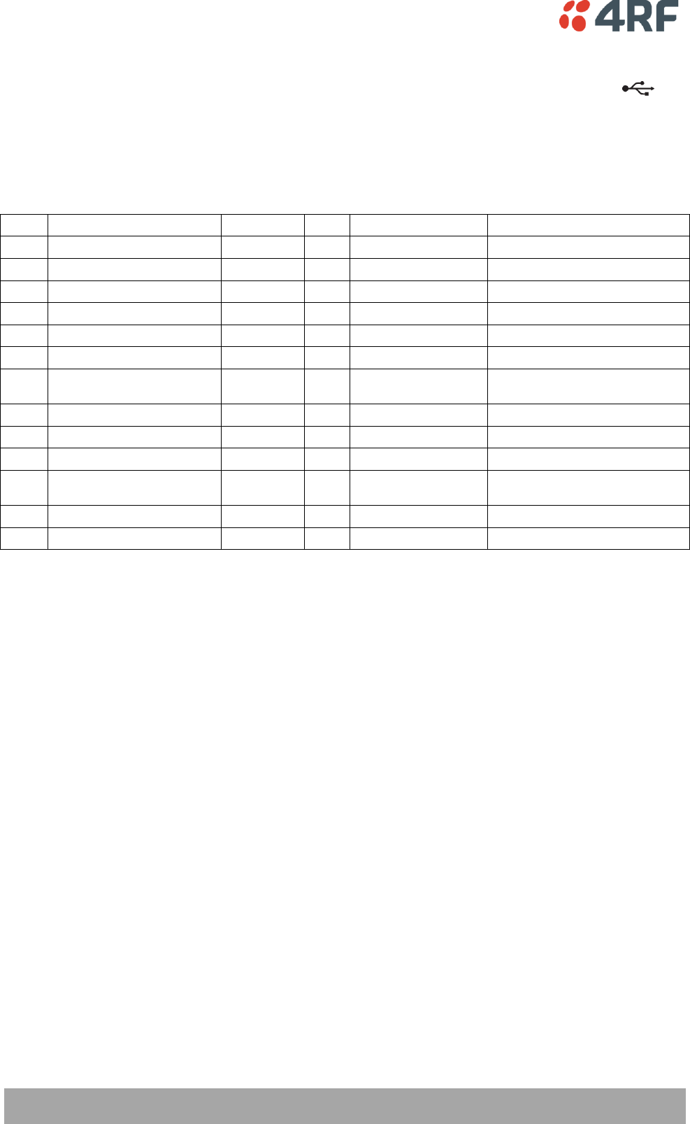
112 | Managing the Radio
Aprisa SR User Manual
Write Alarm History to USB
This parameter when enabled writes the alarm history file to a USB flash drive into the Host Port .
The file is a space delimited text file with a file name in the format ‘alarm_ipaddress_date,time
e.g. ‘alarm_172.17.10.17_2000-01-13,17.13.45.txt’.
The maximum number of event entries that can be stored is 1500 alarms.
The following table is an example of the alarm history file generated:
Index
Event Name
Severity
State
Time
Additional Information
1
softwareStartUp
information
0
2011-05-08,12:26:31.0
Power on Reset
2
softwareStartUp
information
0
2011-05-08,12:56:33.0
Power on Reset
3
protPeerCommunicationsLost
major
1
2011-05-08,12:56:39.0
Ethernet Comm Lost with Peer
4
protSwitchOccurred
information
0
2011-05-08,12:56:39.0
Keepalive missed from Active
5
protPeerCommunicationsLost
cleared
2
2011-05-08,12:56:40.0
Alarm Cleared
6
rfNoReceiveData
warning
1
2011-05-08,12:56:53.0
RF No Rx Data for 6 seconds
7
eth2NoRxData
warning
1
2011-05-08,12:57:03.0
ETH2 has not received data for 21
seconds
8
rfNoReceiveData
cleared
2
2011-05-08,12:57:05.0
9
rfNoReceiveData
warning
3
2011-05-08,12:57:12.0
RF No Rx Data for 6 seconds
10
rfNoReceiveData
cleared
4
2011-05-08,12:57:23.0
11
serialNoRxData
warning
1
2011-05-08,12:57:25.0
Serial has not received data for 44
seconds
12
rfNoReceiveData
warning
5
2011-05-08,12:57:29.0
RF No Rx Data for 6 seconds
13
rfNoReceiveData
cleared
6
2011-05-08,12:57:59.0
State
The State column is an indication of whether the event is active or not. An even number indicates an
inactive state while an odd number indicates an active state.
The AUX LED will flash orange while the file is copying to the USB flash drive.
Delete Alarm History file
This parameter when activated deletes the alarm history file stored in the radio.

Managing the Radio | 113
Aprisa SR User Manual
REBOOT
To reboot the radio:
1. Select Maintenance > General.
2. Tick the ‘Reboot’ checkbox.
3. Click ‘Save’ to apply the changes or ‘Cancel’ to restore the current value.
4. Click ‘OK’ to reboot the radio or ‘Cancel’ to abort.
All the radio LEDS will flash repeatedly for 1 second.
The radio will be operational again in about 10 seconds.
The OK, DATA, and CPU LEDS will light green and the RF LED will be green if the network is operating
correctly.
5. Login to SuperVisor.
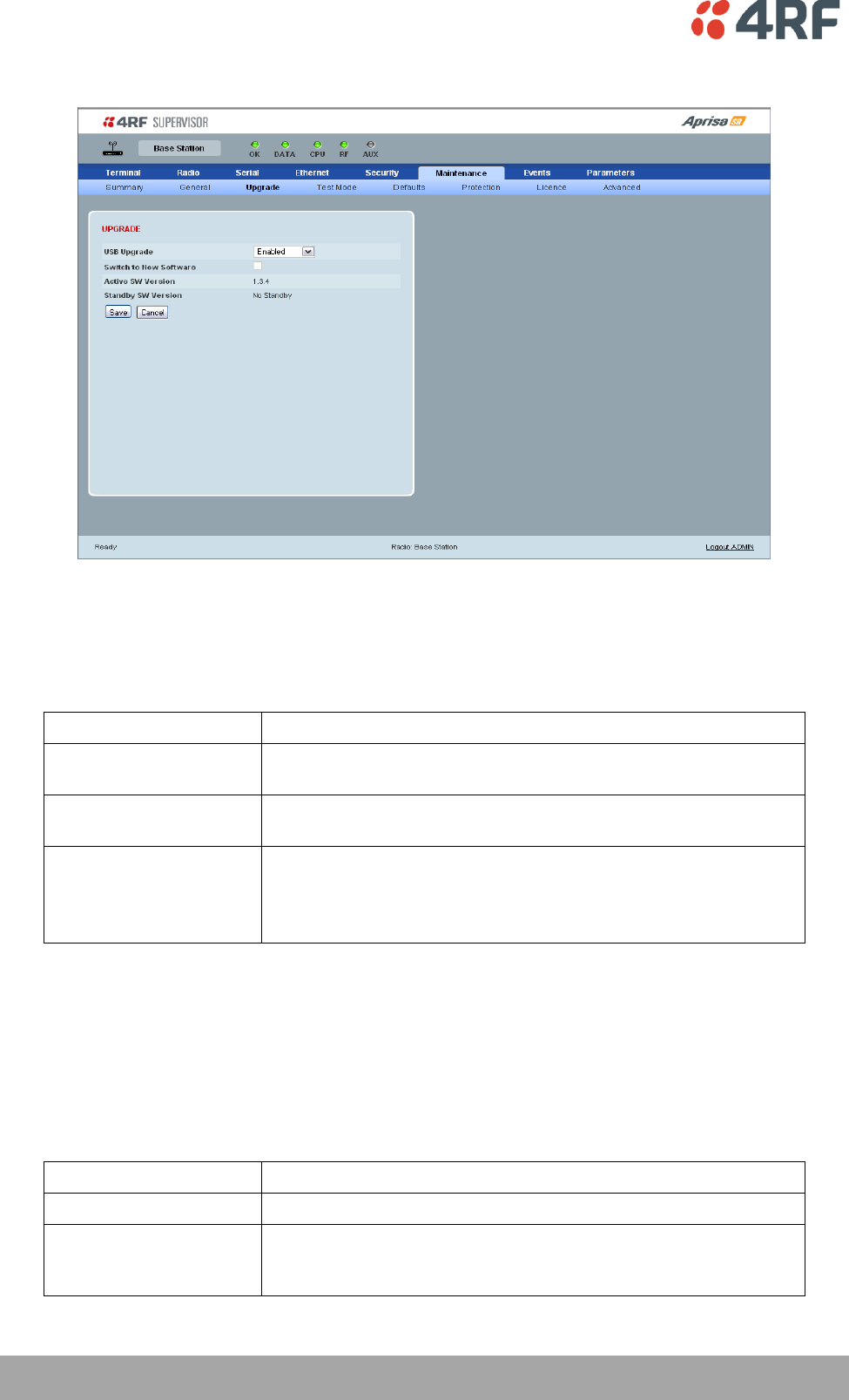
114 | Managing the Radio
Aprisa SR User Manual
Maintenance > Upgrade
UPGRADE
USB Upgrade
This parameter sets the USB upgrade status to one of the values in the following table. The default setting
is enabled.
USB Upgrade Status
Function
Disabled
New software will not be uploaded from a USB flash drive into the
Aprisa SR.
Enabled
New software can be uploaded from a USB flash drive in to the
Aprisa SR and will be activated automatically.
Authenticate
New software can be uploaded from a USB flash drive in to the
Aprisa SR but will not be activated.
The ‘Switch to new Software’ option is used to manually
authenticate the new uploaded software.
To authenticate the new uploaded software:
1. Select Terminal Settings > Maintenance > Upgrade.
2. Tick the ‘Switch to new Software’ checkbox.
3.
The following parameters are show:
Parameter
Function
Active Software Version
This displays the version of software currently operating the radio.
Standby SW Version
If new software has been uploaded to the radio but not activated,
this field displays the version of software uploaded awaiting
activation.
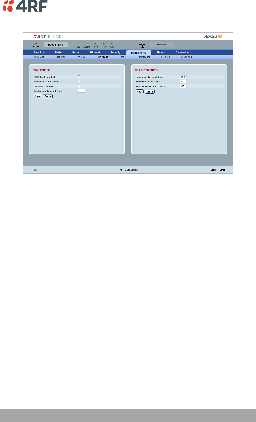
Managing the Radio | 115
Aprisa SR User Manual
Maintenance > Test Mode
TRANSMITTER
PRBS Test Enabled
When active, the transmitter outputs a continuous PRBS signal. This can be used for evaluating the output
spectrum of the transmitter and verifying adjacent channel power and spurious emission products.
Deviation Test Enabled
When active, the transmitter outputs a sideband tone at the deviation frequency used by the CPFSK
modulator. This can be used to evaluate the local oscillator leakage and sideband rejection performance
of the transmitter.
CW Test Enabled
When active, the transmitter outputs a continuous wave signal. This can be used to verify the frequency
stability of the transmitter.

116 | Managing the Radio
Aprisa SR User Manual
RSSI ENTER BUTTON
Response Timeout (ms)
This parameter sets the time Test Mode waits for a response from the Base Station before it times out and
retries. The default setting is 3000 ms.
Transmit Period (sec)
This parameter sets the time between Test Mode requests to the Base Station. The default setting is
5 seconds.
Test Mode Timeout (sec)
This parameter sets the Test Mode timeout period. The radio will automatically exit Test Mode after the
Timeout period. The default setting is 600 seconds.
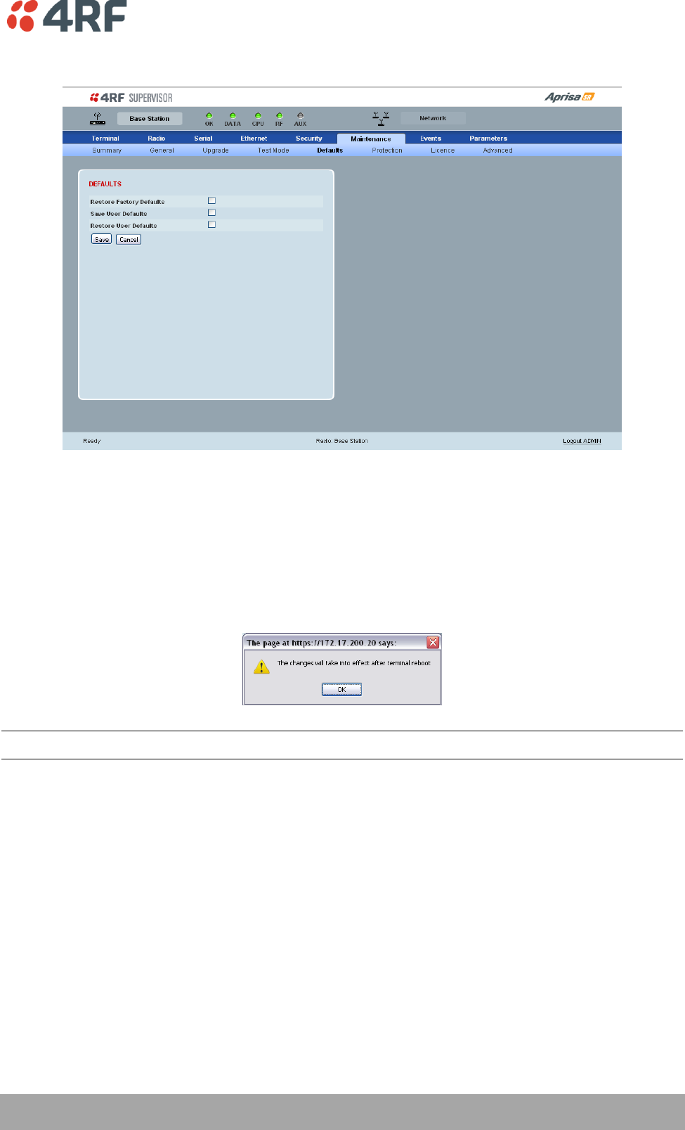
Managing the Radio | 117
Aprisa SR User Manual
Maintenance > Defaults
DEFAULTS
The Maintenance Defaults page is only available for the local terminal.
Restore Factory Defaults
When activated, all radio parameters will be set to the factory default values. This includes resetting the
radio IP address to the default of 169.254.50.10.
Note: Take care using this command.
Save User Defaults
When activated, all current radio parameter settings will be saved to non-volatile memory within the
radio.
Restore User Defaults
When activated, all radio parameters will be set to the settings previously saved using ‘Save User
Defaults‘.

118 | Managing the Radio
Aprisa SR User Manual
Maintenance > Protection
The Maintenance Protection screen is only applicable when the radio is part of a Protected Station.
PROTECTION
Configured as
The 'Configured As' shows if this radio is configured as the primary radio or the secondary radio.
Current State
The 'Current State' shows if this radio is currently Active or Standby.
Switch Count
The 'Switch Count' shows the number of protections switch-overs since the last radio reboot (volatile).
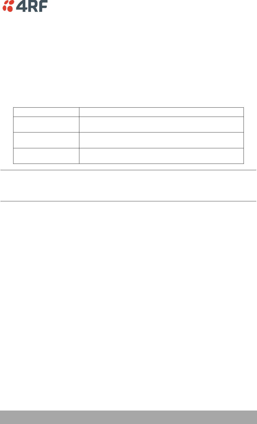
Managing the Radio | 119
Aprisa SR User Manual
SOFTWARE MANUAL LOCK
The software Manual Lock is a software implementation of the Hardware Manual Lock switch on the
Protection Switch. The Software Manual Lock is intended to be used when making changes to the
Protected Station remotely via SuperVisor, to prevent the Protected Station from switching as a result of
the changes being made. See ‘Setting the Software Manual Lock’ on page 33 for a recommended process
to follow to make remote configuration changes.
Lock Active To
This parameter sets the Protection Switch Software Manual Lock. The Software Manual Lock only operates
if the Hardware Manual Lock is deactivated (set to the Auto position).
Option
Function
Automatic
The protection is automatic and switching will be governed by
normal switching and blocking criteria.
Primary
The primary radio will become active i.e. traffic will be switched
to the primary radio.
Secondary
The secondary radio will become active i.e. traffic will be switched
to the secondary radio.
Warning: If the Software Manual Lock is set to Primary or Secondary, the Software Manual Lock must be
set to the same value on both Protected Station radios. If the Software Manual Lock is set to primary on
one radio, and secondary on the other radio, management communication to the radios may be lost if
both radios become set to 'standby' mode.
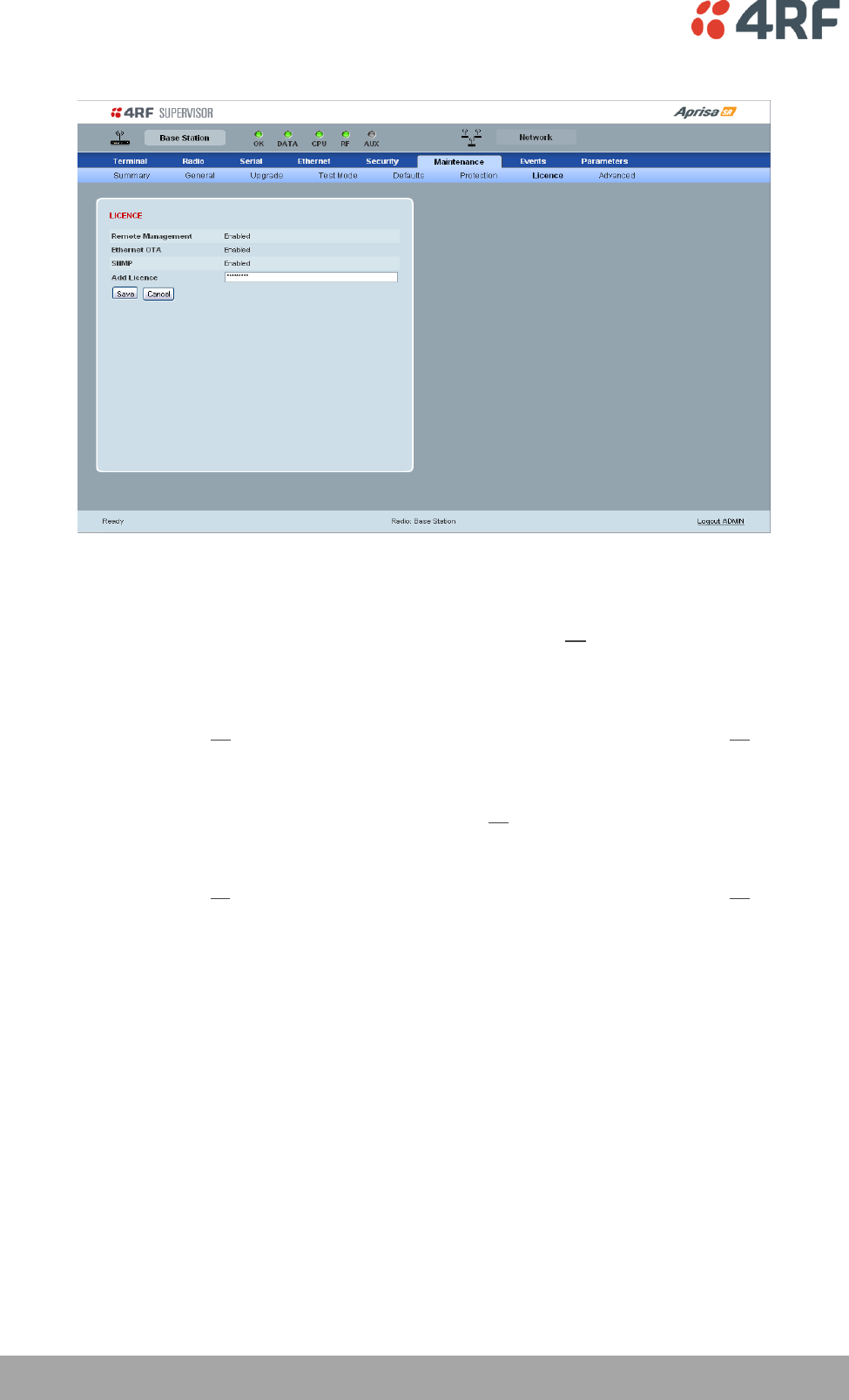
120 | Managing the Radio
Aprisa SR User Manual
Maintenance > Licence
LICENCE
Fully Featured Radio
When a fully featured Aprisa SR radio is purchased (indicated by the AA), it contains the licences which
activate Remote Management, Ethernet Traffic, and SNMP Management e.g. :
Part Number
Part Description
APSR-N400-012-SO-12-ETAA
4RF Aprisa SR, BR, 400-470 MHz, 12.5 kHz, SO, 12 VDC, ET, AA
Serial Only Radio
If a Serial Only Aprisa SR radio is purchased (indicated by the A1), Ethernet Traffic is not enabled.
Part Number
Part Description
APSR-N400-012-SO-12-ETA1
4RF Aprisa SR, BR, 400-470 MHz, 12.5 kHz, SO, 12 VDC, ET, A1
A Feature Licence can be purchased to enable Ethernet Traffic.
Feature Licences
Feature Licences enable features if they were not purchased initially.
One license key is required per feature and per radio serial number.
Part Number
Part Description
APSA-LSRF-FET
4RF Aprisa SR Acc, Licence, Feature, Ethernet Traffic
When Ethernet traffic is enabled, the Ethernet port status must be set to enabled to allow Ethernet data
communication over the radio link (see ‘Ethernet > Port Setup’ on page 93).
Remote Management and SNMP management
In this software version, Remote Management and SNMP management are enabled by default.
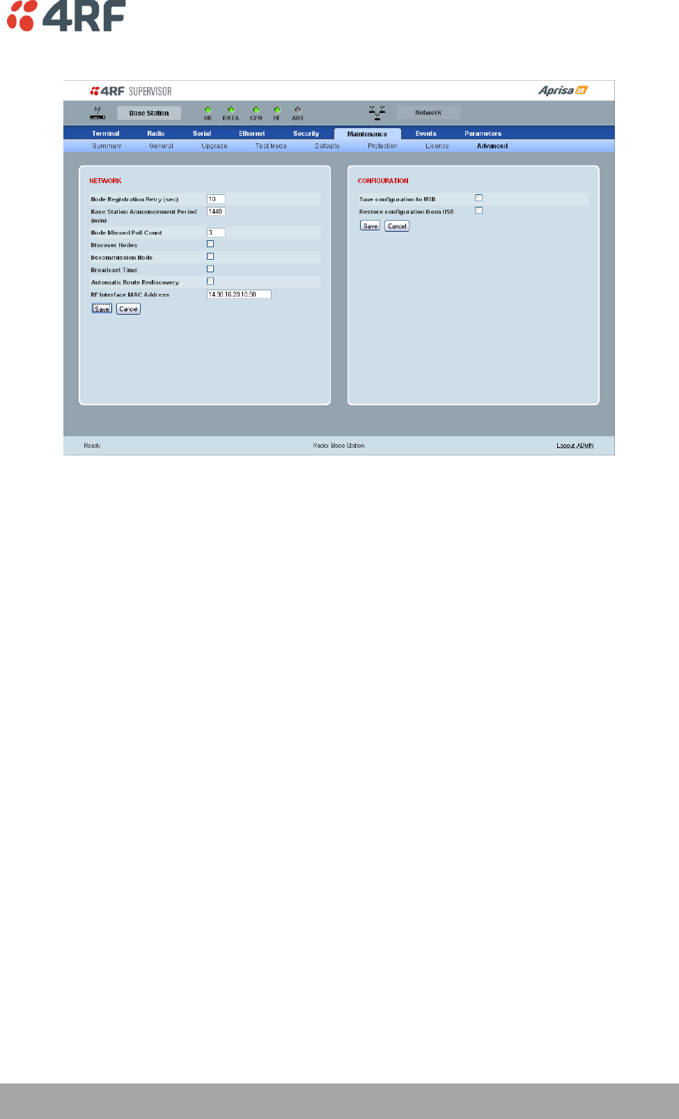
Managing the Radio | 121
Aprisa SR User Manual
Maintenance > Advanced
NETWORK
Node Registration Retry (sec)
This parameter sets the Base Station poll time at startup or the Remote / Repeater Station time between
retries until registered. The default setting is 10 seconds.
Base Station Announcement Period (min)
This parameter sets the period between Base Station polls post startup. The default setting is 1440
minutes.
When a new Base Station powers on, it announces its presence and each remote that receives the
announcement message will be advised that a new Base Station is present and that they should re-
register. This allows the new Base Station to populate its Network Table, with knowledge of the nodes in
the network.
If, during this initial period, there is some temporary path disturbance to one or more remotes, they may
miss the initial announcement messages and be left unaware of the Base Station change. For this reason,
the Base Station must periodically send out announcement messages to pick up any stray nodes and the
period of these messages is the Base Station Announcement Period.
Setting this parameter to 0 will stop further announcement messages being transmitted.
Node Missed Poll Count
This parameter sets the number of times the Base Station attempts to poll the FAN at startup or if a
duplicate IP is detected when a Remote / Repeater Station is replaced. The default setting is 3.
122 | Managing the Radio
Aprisa SR User Manual
Discover Nodes
This parameter when activated triggers the Base Station to poll the FAN with Node Missed Poll Count and
Node Registration Retry values.
Decommission Node
This parameter when activated resets the FAN registrations to remove the entire FAN from service.
Note: Take care using this option.
Broadcast Time
This parameter when activated sends the Base Station Date / Time setting to all the Remote and Repeater
Stations in the FAN and sets their Date / Time. This option applies to the Base Station only.
Automatic Route Rediscovery
This parameter enables the radio to transmit route discovery messages when packets are unacknowledged.
When enabled, unacknowledged unicast packets are converted into uni-broadcast messages and sent
through the network. All nodes see the message and populate their routing tables accordingly.
When the destination node is reached, it sends a route response message via the shortest path. The
intermediate nodes see this message and populate their routing tables in the reverse direction, thus re-
establishing the route.
The default setting is enabled.
RF Interface MAC address
This parameter is only applicable when the radio is part of a Protected Station.
This RF Interface MAC address is used to define the MAC address of the Protection Switch. This address is
entered into both Protected Station radios in the factory.
If a replacement Protection Switch is installed, the replacement unit MAC address must be entered in both
radios (see ‘Replacing a Faulty Protection Switch’ on page 34).
The Protection Switch RF Interface MAC address is shown on the Protection Switch label:

Managing the Radio | 123
Aprisa SR User Manual
CONFIGURATION
Save Configuration to USB
This parameter saves all user configuration settings to a binary encrypted file on the USB root directory
with filename of asrcfg_1.3.4. Some parameters are not saved e.g. security passwords, licence keys etc.
Restore Configuration from USB
This parameter restores all user configuration settings from a binary encrypted file on the USB root
directory with filename of asrcfg_1.3.4.
NOTE: Activating this function will over-write all existing configuration settings in the radio (except for
the non-saved settings e.g. security passwords, licence keys etc).
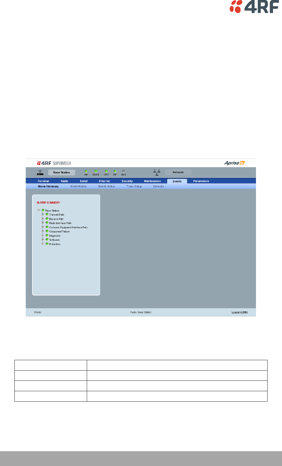
124 | Managing the Radio
Aprisa SR User Manual
Events
There are two types of events that can be generated on the Aprisa SR radio. These are:
1. Alarm Events
Alarm Events are generated to indicate a problem on the radio.
2. Informational Events
Informational Events are generated to provide information on key activities that are occurring on the
radio. These events do not indicate an alarm on the radio and are used to provide information only.
See ‘Alarm Types and Sources’ on page 144 for a complete list of events.
Events > Alarm Summary
ALARM SUMMARY
The Alarm Summary is a display tree that displays the current states of all radio alarms. The alarm states
refresh automatically every 12 seconds.
LED Colour
Severity
Green
No alarm
Orange
Warning alarm
Red
Critical, major or minor alarm
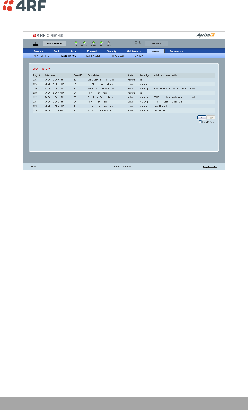
Managing the Radio | 125
Aprisa SR User Manual
Events > Event History
EVENT HISTORY
The last 1500 events are stored in the radio. The complete event list can be downloaded to a USB flash
drive (see ‘Write Alarm History to USB’ on page 112).
The Event History can display the last 50 events stored in the radio in blocks of 8 events.
The Next button will display the next page of 8 events and the Prev button will display the previous page
of 8 events. Using these buttons will disable Auto Refresh to prevent data refresh and page navigation
contention.
The last 50 events stored in the radio are also accessible via an SNMP command.
Auto Refresh
The Event History page selected will refresh automatically every 12 seconds if the Auto Refresh is ticked.
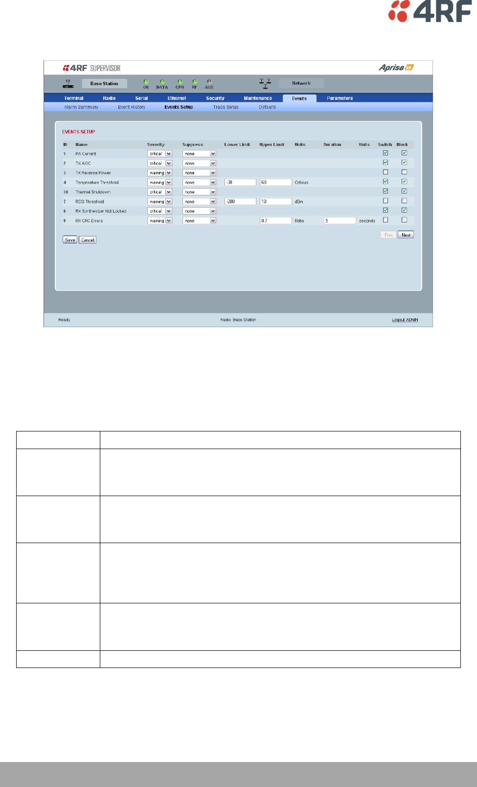
126 | Managing the Radio
Aprisa SR User Manual
Events > Events Setup
EVENTS SETUP
Alarm event parameters can be configured for all alarm events (see ‘Alarm Events’ on page 144).
Severity
The Severity parameter sets the alarm severity.
Severity
Function
Critical
The Critical severity level indicates that a service affecting condition has occurred and
an immediate corrective action is required. Such a severity can be reported, for
example, when a managed object becomes totally out of service and its capability must
be restored.
Major
The Major severity level indicates that a service affecting condition has developed and
an urgent corrective action is required. Such a severity can be reported, for example,
when there is a severe degradation in the capability of the managed object and its full
capability must be restored.
Minor
The Minor severity level indicates the existence of a non-service affecting fault
condition and that corrective action should be taken in order to prevent a more serious
(for example, service affecting) fault.
Such a severity can be reported, for example, when the detected alarm condition is not
currently degrading the capacity of the managed object.
Warning
The Warning severity level indicates the detection of a potential or impending service
affecting fault, before any significant effects have been felt. Action should be taken to
further diagnose (if necessary) and correct the problem in order to prevent it from
becoming a more serious service affecting fault.
Information
No problem indicated – purely information

Managing the Radio | 127
Aprisa SR User Manual
Suppress
The Suppress parameter determines if the action taken by an alarm.
Suppress
Function
None
Alarm triggers an event trap and is logged in the radio
Traps
Alarm is logged in the radio but does not trigger an event trap
Traps and Log
Alarm neither triggers an event trap nor is logged in the radio
Lower Limit / Upper Limit
Threshold alarm events have lower and upper limit settings. The alarm is activated if the current reading
is outside the limits.
Example: 9 RX CRC Errors
The Upper Limit is set to 0.7 and the Duration is set to 5 seconds.
If in any 5 second period, the total number of errored packets divided by the total number of received
packets exceeds 0.7, the alarm will activate.
Units (1)
The Units parameter shows the unit for the Lower Limit and Upper Limit parameters.
Duration
The Duration parameter determines the period to wait before an alarm is raised if no data is received.
Units (2)
The Units parameter shows the unit for the Duration parameters.
Switch
The Switch parameter determines if the alarm when active causes a switch over of the Protection Switch.
This parameter is only applicable when the radio is part of a Protected Station.
Block
The Block parameter determines if the alarm is prevented from causing a switch over of the Protection
Switch.
This parameter is only applicable when the radio is part of a Protected Station.
The Next button will display the next page of 8 alarm events and the Prev button will display the previous
page of 8 alarm events.
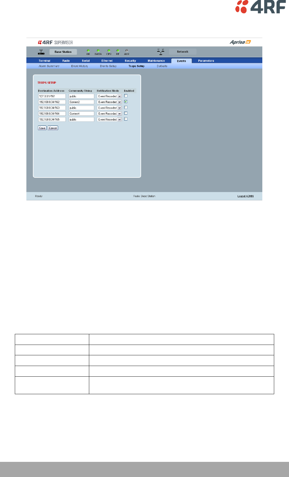
128 | Managing the Radio
Aprisa SR User Manual
Events > Traps Setup
TRAPS SETUP
All events can generate traps. The types of traps that are supported are defined in the ‘Notification
Mode’.
Destination Address
An SNMP Trap Destination is the IP address of a station running an SNMP manager.
Community String
A community string is sent with the IP address for security. The default community string is ‘public’.
Notification Mode
The Notification Mode defines when an event related trap is sent.
Notification Mode
Function
None
No event related traps are sent.
Event Recorded
When an event is recorded in the event history log, a trap is sent.
Event Updated
When an event is updated in the event history log, a trap is sent.
All Events
When an event is recorded or updated in the event history log, a
trap is sent.
Enabled
The Enabled parameter determines if the entry is used.
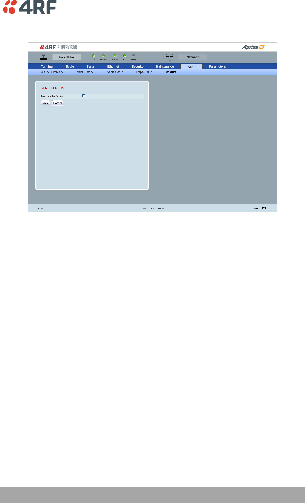
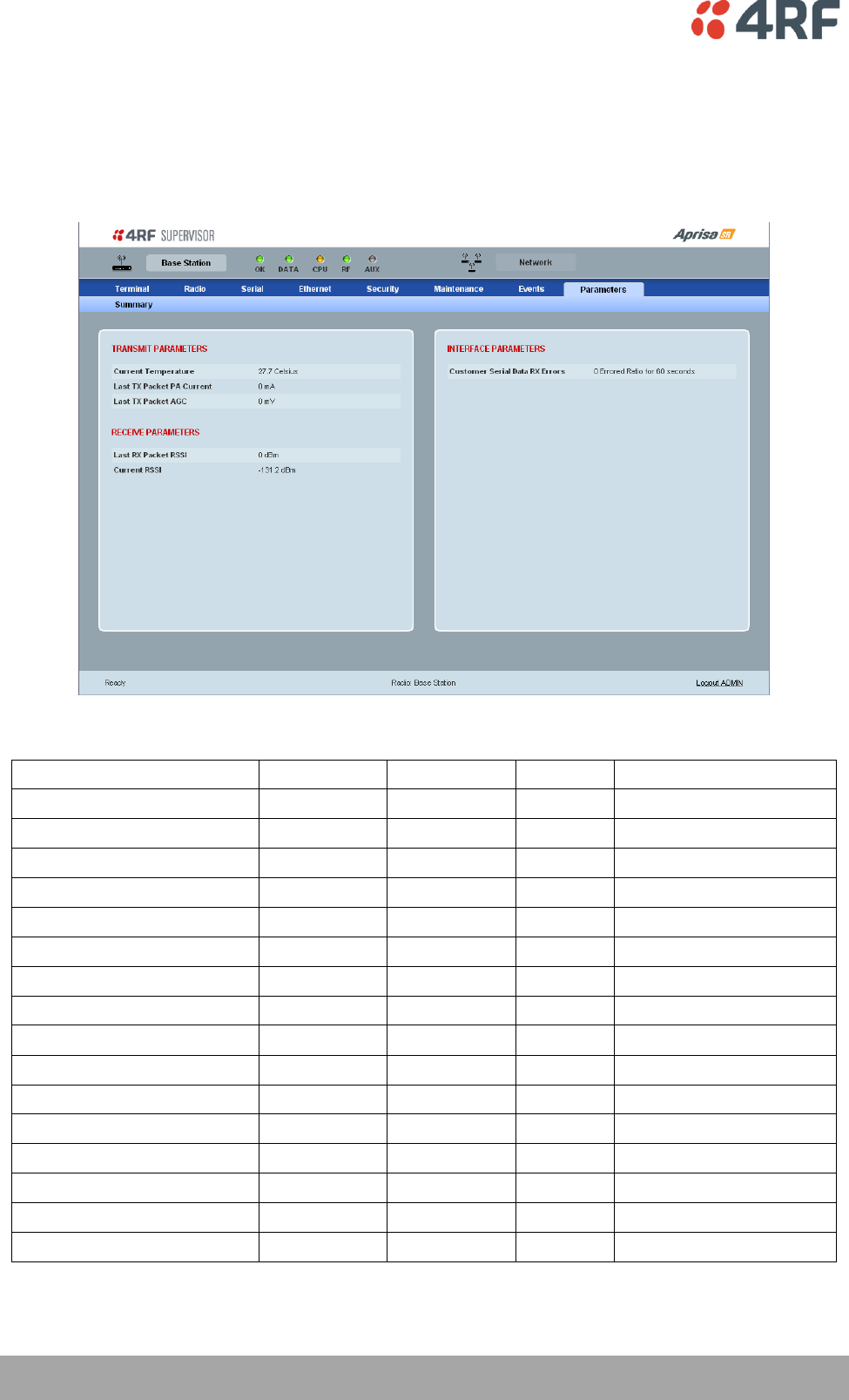
130 | Managing the Radio
Aprisa SR User Manual
Parameters
Parameters > Summary
The Parameters Summary screen is a dynamic page that will display the parameters associated with the
active alarms, set on ‘Events > Events Setup’ on page 126. This screen is an example only showing some
monitored parameters with active alarms.
The following is a list of alarm events that are monitored:
Monitored Parameter
Unit
Scale Factor
Event ID
Event Display Text
Current Temperature
Celsius
10
4
Temperature Threshold
Last RX Packet RSSI
dBm
10
7
RSSI Threshold
Last Sample RX CRC Error
Ratio
100
9
RX CRC Errors
Last Sample RF RX Data
Count
1
34
RF No Receive Data
Last Sample Eth1 RX Data
Count
1
10
Port 1 Eth No Receive Data
Customer Eth1 Data RX Errors
Ratio
100
11
Port 1 Eth Receive Errors
Customer Eth1 Data TX Errors
Ratio
100
12
Port 1 Eth Transmit Errors
Last Sample Eth2 RX Data
Count
1
35
Port 2 Eth No Receive Data
Customer Eth2 Data RX Errors
Ratio
100
36
Port 2 Eth Receive Errors
Customer Eth2 Data TX Errors
Ratio
100
37
Port 2 Eth Transmit Errors
Last Sample Serial RX Data
Count
1
13
Serial Data No Receive Data
Customer Serial Data RX Errors
Ratio
100
14
Serial Data Receive Errors
Last TX Packet PA Current
mA
1
None
Last TX Packet AGC
mV
1
None
Last TX Packet Reverse Power
dB
10
None
Current RSSI
dBm
10
None
If an associated alarm event occurs, the Parameters table will display the current value for that
parameter. The refresh time is 12 seconds.
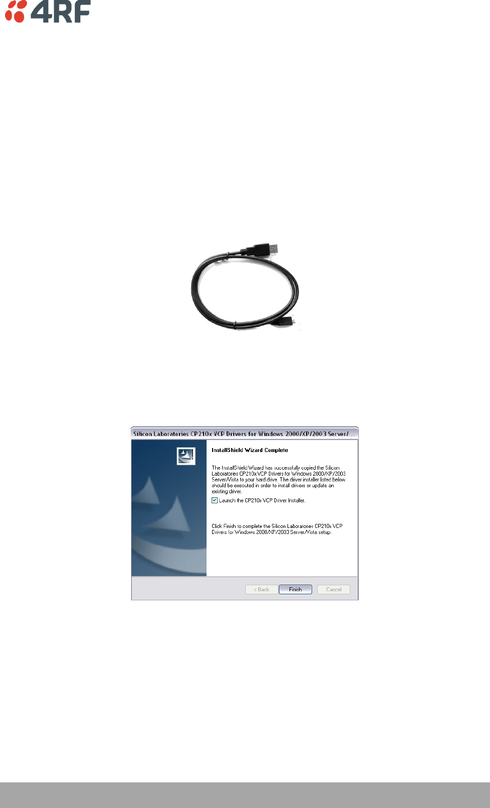
Managing the Radio | 131
Aprisa SR User Manual
Command Line Interface
The Aprisa SR has a Command Line Interface (CLI) which provides basic product setup and configuration.
This can be useful if you need to confirm the radio's IP address, for example.
You can password-protect the Command Line Interface to prevent unauthorized users from modifying
radio settings.
This interface can be accessed via an Ethernet Port (RJ-45) or the Management Port (USB micro type B).
Connecting to the Management Port
A USB Cable USB A to USB micro B, 1m is provided with each radio.
1. Connect the USB A to your computer USB port and the USB micro B to the management port of the
Aprisa SR (MGMT).
2. Unzip and install the USB Serial Driver CP210x_VCP_Win2K_XP_S2K3.zip on your computer. This file is
on the Information and setup CD supplied with the radio.
3. Go to your computer device manager (Control Panel > System > Hardware > Device Manager)
4. Click on ‘Ports (COM & LPT)’
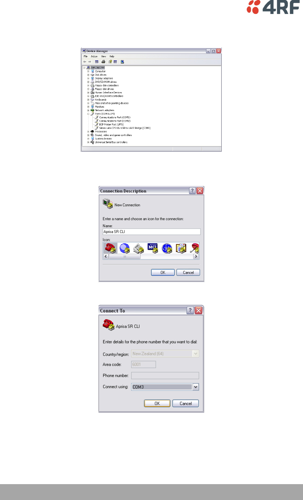
132 | Managing the Radio
Aprisa SR User Manual
5. Make a note of the COM port which has been allocated to the ‘Silicon Labs CP210x USB to UART
Bridge’ (COM3 in the example below)
6. Open HyperTerminal Session (Start > All Programs > Accessories > Communications > HyperTerminal)
7. Enter a name for the connection (Aprisa SR CLI for example) and click OK.
8. Select the COM port from the Connect Using drop-down box that was allocated to the UART USB.
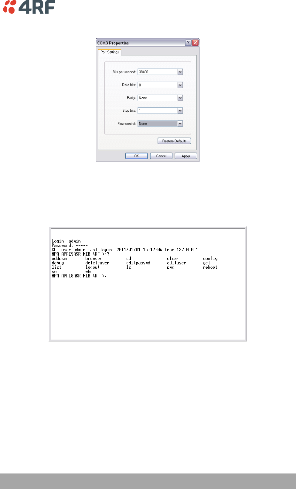
Managing the Radio | 133
Aprisa SR User Manual
9. Set the COM port settings as follows:
10. Click OK. The HyperTerminal window will open.
11. Press the Enter key to initiate the session.
12. Login to the Aprisa SR CLI with a default Username ‘admin’ and Password ‘admin’.
The top level CLI menu is shown:
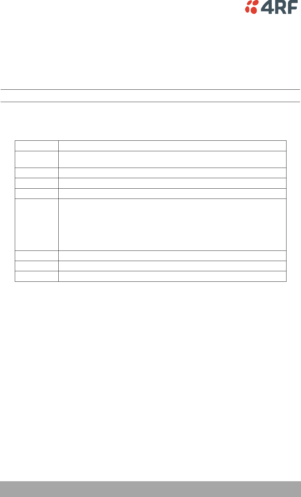
134 | Managing the Radio
Aprisa SR User Manual
CLI Commands
To enter a CLI command:
1. Type the first few characters of the command and hit Tab. This auto completes the command.
2. Enter the command string and enter.
Note: The CLI commands are case sensitive.
The top level CLI command list is displayed by typing a ? at the command prompt.
The following is a list of the top level CLI commands and their usage:
CLI Command
Usage
adduser
adduser [-g <password aging>] [-a <account aging>] [-i <role>] <userName>
<userPassword>
browser
browser <state(STR)>
cd
cd <changeMode(STR)>
clear
Clears the screen
config
config
userdefault
save
restore
factorydefault
restore
deleteuser
deleteuser <userName>
editpasswd
editpasswd <oldpassword> <newpassword>
edituser
edituser [-p <password>] [-g <password aging>] [-a <account aging>] [-i]
Managing the Radio | 135
Aprisa SR User Manual
get
get [-m <mib name>] [-n <module name>] <attribute name> [indexes]
list
list <tablename>
logout
Logs out from the CLI
ls
Lists the settings for:
(-) EthernetAdvanced
(-) EthernetControllers
(-) EthernetPorts
(-) EthL2FilterTable
(-) MaintenanceAdvanced
(-) MaintenanceDefaults
(-) MaintenanceGeneral
(-) MaintenanceLicence
(-) MaintenanceTestmode
(-) MaintenanceUpgrade
(+) NetworkTable
(-) RadioChannelAccess
(-) RadioRfSettings
(-) SecuritySettings
(+) SecurityUserTable
(-) SerialAdvanced
(-) SerialFlowControl
(-) SerialPortSettings
(-) TerminalDetails
(-) TerminalOperatingMode
reboot
Reboots the radio
set
set [-m <mib name> ] [-n <module name>] <attribute name> <attribute set v]
who
Shows the users currently logged into the radio
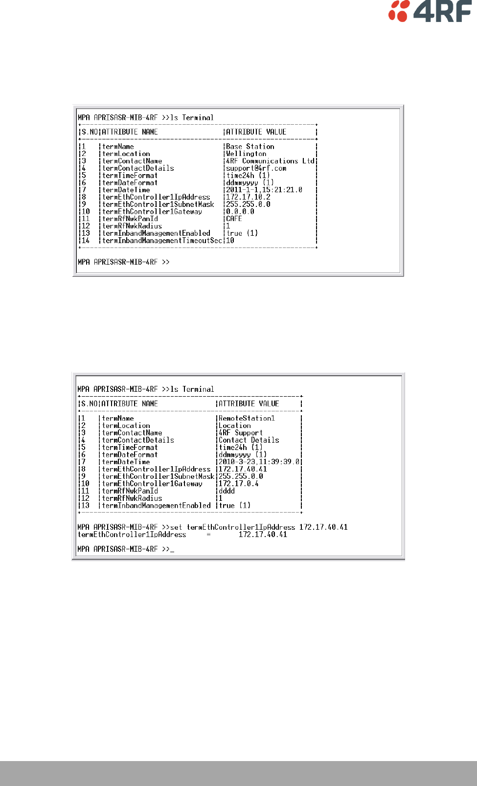
136 | Managing the Radio
Aprisa SR User Manual
Viewing the CLI Terminal Summary
At the command prompt, type ‘ls Terminal’
Changing the Radio IP Address with the CLI
At the command prompt, type ‘set termEthController1IpAddress xxx.xxx.xxx.xxx’

Managing the Radio | 137
Aprisa SR User Manual
In-Service Commissioning
Before You Start
When you have finished installing the hardware, RF and the traffic interface cabling, the system is ready
to be commissioned. Commissioning the radio is a simple process and consists of:
1. Powering up the radios.
2. Configuring all radios in the FAN using SuperVisor.
3. Aligning the antennas.
4. Testing that the links are operating correctly.
5. Connecting up the client or user interfaces.
What You Will Need
Appropriately qualified commissioning staff at both ends of each link.
Safety equipment appropriate for the antenna location at both ends of each link.
Communication equipment, that is, mobile phones or two-way radios.
SuperVisor software running on an appropriate laptop, computer, or workstation at the Base
Station radio.
Tools to facilitate loosening and re-tightening the antenna pan and tilt adjusters.
Predicted receiver input levels and fade margin figures from the radio link budget.

138 | Managing the Radio
Aprisa SR User Manual
Antenna Alignment
A Base Station omni directional collinear antenna has a vertical polarization. The Remote Station yagi
antennas must also have vertical polarization.
Aligning the Antennas
Align the Remote Station yagi antennas by making small adjustments while monitoring the RSSI. The Aprisa
SR has a Test Mode which presents a real time visual display of the RSSI on the front panel LEDs. This can
be used to adjust the antenna for optimum signal strength (see ‘Test Mode’ on page 26).
Note: Low gain antennas need less adjustment in elevation as they are simply aimed at the horizon. They
should always be panned horizontally to find the peak signal.
1. Press and hold the ENTER button on the radio LED panel until all the LEDs flash green (about 3 - 5
seconds).
Note: The time for the LEDs to display the RSSI result is variable, depending on the network traffic,
and can be up to 5 seconds. Small antenna adjustments should be made and then wait for the display
to refresh.
The RSSI poll refresh rate can be set with the SuperVisor command ‘Transmit Period’ (see
‘Maintenance > Test Mode’ on page 115).
2. Move the antenna through a complete sweep horizontally (pan). Note down the RSSI reading for all the
peaks in RSSI that you discover in the pan.
3. Move the antenna to the position corresponding to the maximum RSSI value obtained during the pan.
Move the antenna horizontally slightly to each side of this maximum to find the two points where the
RSSI drops slightly.
4. Move the antenna halfway between these two points and tighten the clamp.
5. If the antenna has an elevation adjustment, move the antenna through a complete sweep (tilt)
vertically. Note down the RSSI reading for all the peaks in RSSI that you discover in the tilt.
6. Move the antenna to the position corresponding to the maximum RSSI value obtained during the tilt.
Move the antenna slightly up and then down from the maximum to find the two points where the RSSI
drops slightly.
7. Move the antenna halfway between these two points and tighten the clamp.
8. Recheck the pan (steps 2-4) and tighten all the clamps firmly.
9. To exit Test Mode, press and hold the ENTER button until all the LEDs flash red (about 3 – 5 seconds).

Maintenance | 139
Aprisa SR User Manual
9. Maintenance
There are no user-serviceable components within the radio.
All hardware maintenance must be completed by 4RF or an authorized service centre.
Do not attempt to carry out repairs to any boards or parts.
Return all faulty radios to 4RF or an authorized service centre.
For more information on maintenance and training, please contact 4RF Customer Services at
support@4rf.com.
CAUTION: Electro Static Discharge (ESD) can damage or destroy the sensitive electrical components in the
radio.
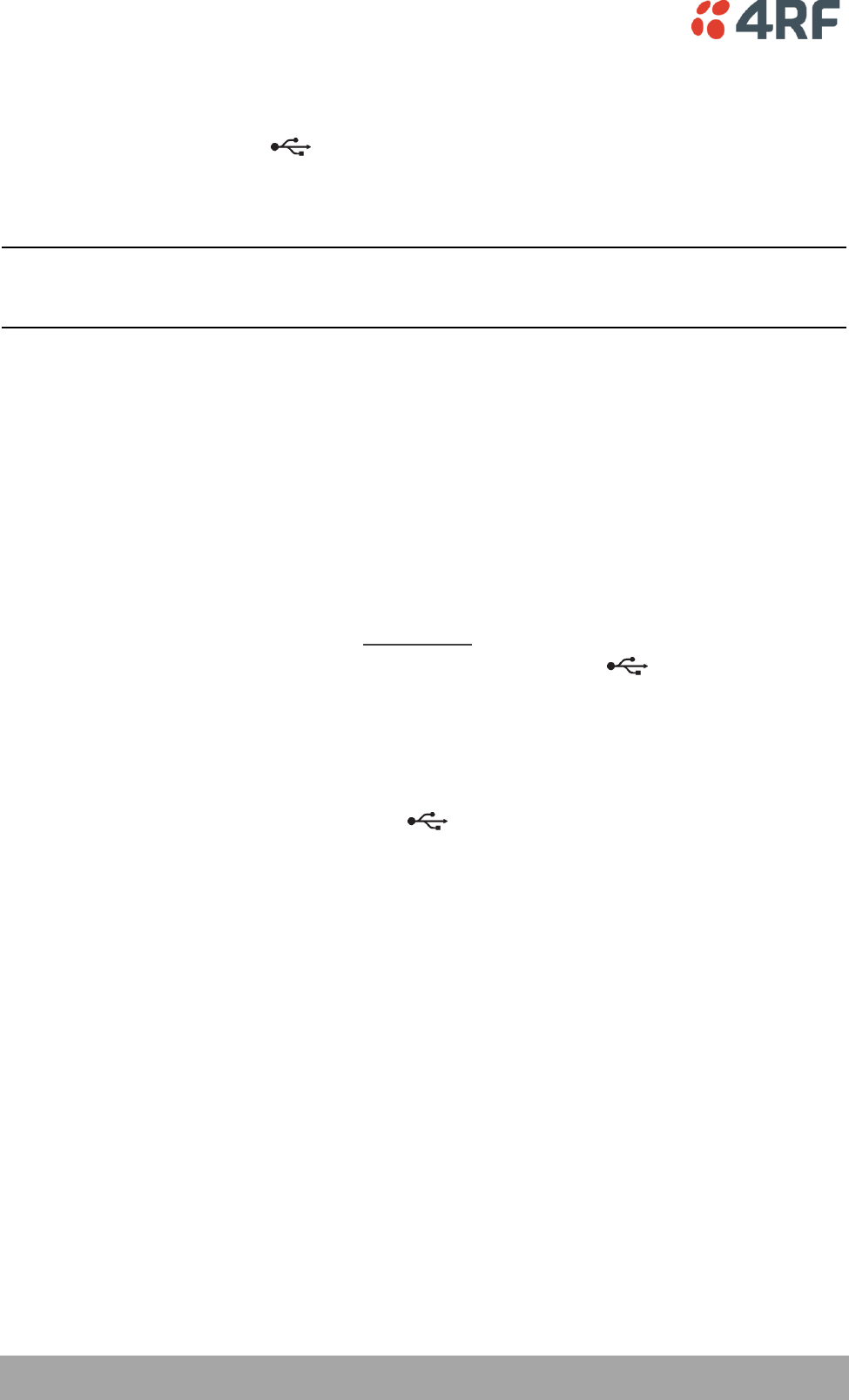
140 | Maintenance
Aprisa SR User Manual
Radio Software Upgrade
The Aprisa SR radio software can be upgraded simply by plugging a USB flash drive containing the new
software into the USB A host port on the Aprisa SR front panel.
The software upgrade procedure is different for an Aprisa SR Protected Station (see ‘Protected Station
Software Upgrade’ on page 32).
Note: If a radio has been configured for a Protection Type of ‘Redundant’ (see ‘Terminal > Protection’ on
page 77), and that radio is no longer part of a Protected Station, the Protection Type must be changed to
‘None’ before the radio software upgrade can be achieved.
Upgrade Process
To minimize disruption of link traffic and prevent your radios from being rendered inoperative, please
follow the procedures described in this section together with any additional information or instructions
supplied with the upgrade package.
The radio software must be identical on all radios in the FAN.
To upgrade the Aprisa SR radio software:
1. Check that the SuperVisor USB Upgrade setting is set to ‘Enabled’ (see ‘Maintenance > Upgrade’ on
page 114).
2. Unzip the software release files in to the root directory of a USB flash drive.
3. Power off the Aprisa SR and insert the USB flash drive into the Host Port .
4. Power on the Aprisa SR.
5. The software upgrade process is complete when the OK LED lights solid orange. This can take about 2
minutes.
The software will have loaded in to the radio Standby SW location.
6. Remove the USB flash drive from the Host Port .
7. Power cycle the Aprisa SR.
Login in to the radio being upgraded and view the Active and Standby SW version (see ‘ Summary’ on page
70).
If the upgrade process was successful, the Active SW Version will show the new software version and the
Standby SW Version will be shown as ‘No Standby’.
If the upgrade process did not start, the Aprisa SR could already be operating on the version of software
on the USB flash drive. This will be indicated by flashing OK LED and then the OK, DATA and CPU will light
steady green.
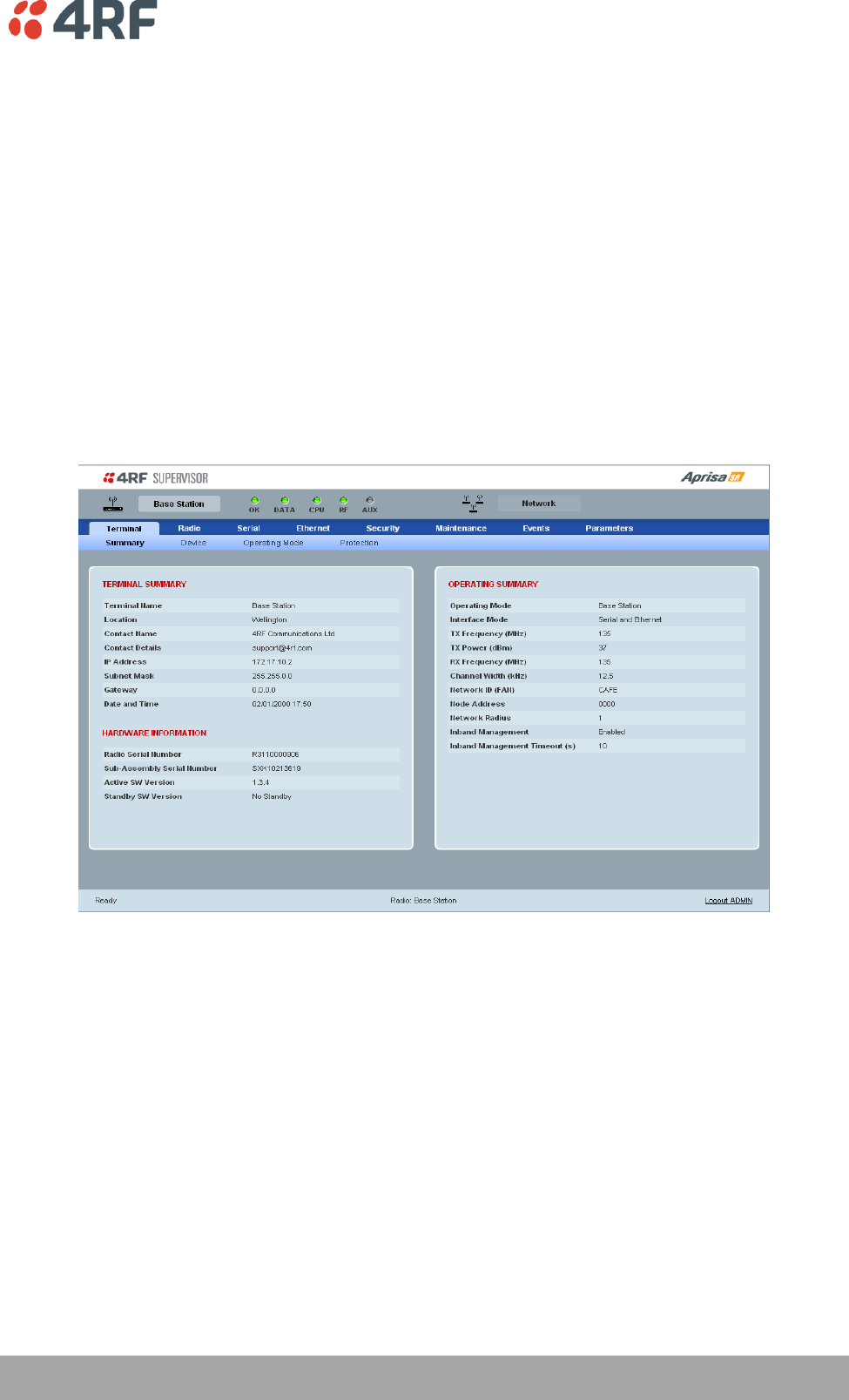
Maintenance | 141
Aprisa SR User Manual
If the radio is not operating on the new software (after the power cycle), it could be caused by the
SuperVisor USB Upgrade setting set to ‘Authenticate’ (see ‘Maintenance > Upgrade’ on page 114).
The new software will have uploaded in to the Aprisa SR but will not have activated. The new software
version will be displayed in the Standby SW version.
In this case, go to SuperVisor ‘Maintenance > Upgrade’ on page 114 and tick the ‘Switch to new Software’
checkbox and click ‘Save’ to apply the changes.
If any Display Panel LED flashes red or is steady red during the upgrade process, it indicates that the
upgrade has failed. This could be caused by incorrect files on the USB flash drive or a radio hardware
failure.
To view the uploaded software version:
Select Terminal Settings > Terminal > Summary
The version of the uploaded software will be displayed in the ‘Standby SW Version field.
Software Downgrade
Radio software can also be downgraded if required. This may be required if a new radio is purchased for
an existing network which is operating on an earlier software release.
The downgrade process is the same as the upgrade process.
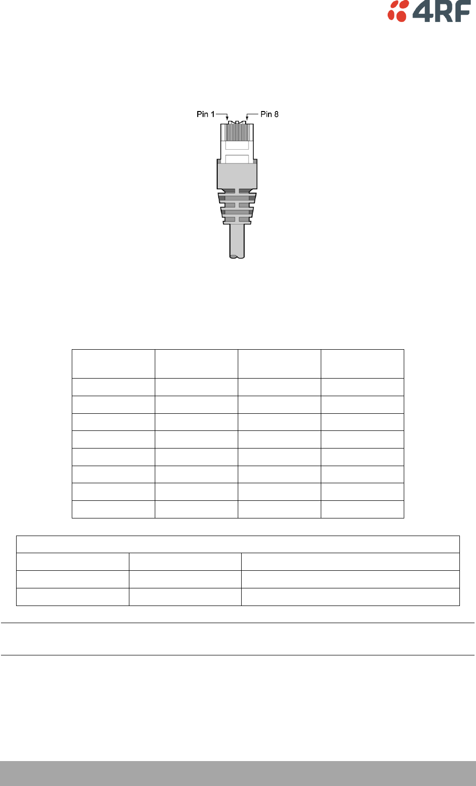
142 | Interface Connections
Aprisa SR User Manual
10. Interface Connections
RJ-45 Connector Pin Assignments
RJ-45 pin numbering
Ethernet Interface Connections
Pin number
Pin function
Direction
TIA-568A wire
colour
1
Transmit
Output
Green/white
2
Transmit
Output
Green
3
Receive
Input
Orange/white
4
Not used
Blue
5
Not used
Blue/white
6
Receive
Input
Orange
7
Not used
Brown/white
8
Not used
Brown
RJ-45 connector LED indicators
LED
Status
Explanation
Green
On
Ethernet signal received
Green
Flashing
Indicates data traffic present on the interface
Note: Do not connect Power over Ethernet (PoE) connections to the Aprisa SR Ethernet ports as this will
damage the port.
Interface Connections | 143
Aprisa SR User Manual
RS-232 Serial Interface Connections
The RS-232 Serial Interface is always configured as a DCE:
RJ45
Pin Number
Pin Function
Direction
TIA-568A Wire
Colour
1
RTS
Input
Green / white
2
DTR
Input
Green
3
TXD
Input
Orange / white
4
Ground
Blue
5
DCD
Output
Blue / white
6
RXD
Output
Orange
7
DSR
Output
Brown / white
8
CTS
Output
Brown
Protection Switch Remote Control Connections
1 2 3 4
Pin Number
1
2
3
4
Function
A radio active
Ground
B radio active
Ground

144 | Alarm Types and Sources
Aprisa SR User Manual
11. Alarm Types and Sources
Alarm Types
There are three types of alarm event configuration types:
1. Threshold Type
These alarm events have lower and upper limits. An alarm is raised if current reading is outside the limits.
Note: the limits for PA Current, TX AGC, TX Reverse Power and Thermal shutdown are not user
configurable.
2. Error Ratio Type
This is the ratio of bad packets vs total packets in the defined sample duration.
For Serial, it is the ratio of bad characters vs total characters in the duration seconds. An alarm is raised if
current error ratio is greater than the configured ratio. The error ratio is configured in ‘Upper Limit’ field
and accepts value between 0 and 1. Monitoring of these events can be disabled by setting the duration
parameter to 0.
3. Sample Duration Type
Used for No Receive data events type. An alarm is raised if no data is received in the defined sample
duration. Monitoring of these events can be disabled by setting the duration parameter to 0.
See ‘Events > Events Setup’ on page 126 for setup of alarm thresholds / sample durations etc.
Alarm Events
Transmitter Alarms
Event ID
Event Display
Text
Default
Severity
Configuration
Type
Function
1
PA Current
critical(1)
Threshold Type
Alarm to indicate that the current drawn
by the transmitter power amplifier is
outside defined limits.
2
TX AGC
critical(1)
Threshold Type
Alarm to indicate that the variable gain
control of the transmitter is outside
defined limits.
3
TX Reverse
Power
warning(4)
Threshold Type
Alarm to indicate that the antenna is not
connected to the radio
4
Temperature
Threshold
warning(4)
Threshold Type
Alarm to indicate that the transmitter
temperature is outside defined limits.
31
Thermal
Shutdown
critical(1)
Threshold Type
Alarm to indicate that the transmitter has
shutdown due to excessively high
temperature.
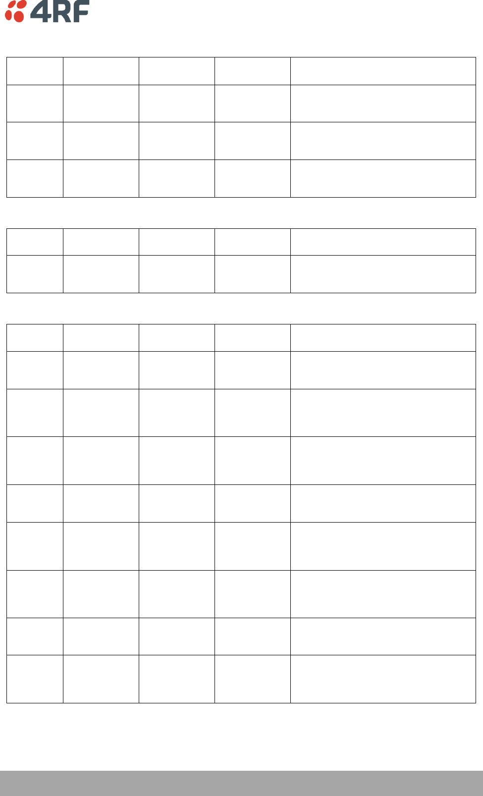
Alarm Types and Sources | 145
Aprisa SR User Manual
Receiver Alarms
Event ID
Event Display
Text
Default
Severity
Configuration
Type
Function
7
RSSI Threshold
warning(4)
Threshold Type
Alarm to indicate that the receiver RSSI
reading taken on the last packet received
is outside defined limits.
8
RX Synthesizer
Not Locked
critical(1)
Not
Configurable
Alarm to indicate that the receiver
Synthesizer is not locked on the RF
received signal.
9
RX CRC Errors
warning(4)
Error Ratio
Type
Alarm to indicate that the data received
on the RF path contains errors at a higher
rate than the defined error rate threshold.
Radio Interface Path Alarms
Event ID
Event Display
Text
Default
Severity
Configuration
Type
Function
34
RF No Receive
Data
warning(4)
Sample
Duration Type
Alarm to indicate that there is no data
received on the RF path in the defined
duration period.
Customer Equipment Interface Path Alarms
Event ID
Event Display
Text
Default
Severity
Configuration
Type
Function
10
Port 1 Eth No
Receive Data
warning(4)
Sample
Duration Type
Alarm to indicate that Ethernet port 1 has
no received input signal in the defined
duration period.
11
Port 1 Eth Data
Receive Errors
warning(4)
Error Ratio
Type
Alarm to indicate that Ethernet port 1
received input signal contains errors at a
higher rate than the defined error rate
threshold.
12
Port 1 Eth Data
Transmit Errors
warning(4)
Error Ratio
Type
Alarm to indicate that Ethernet port 1
transmitted output signal contains errors
at a higher rate than the defined error
rate threshold.
35
Port 2 Eth No
Receive Data
warning(4)
Sample
Duration Type
Alarm to indicate that Ethernet port 2 has
no received input signal in the defined
duration period.
36
Port 2 Eth Data
Receive Errors
warning(4)
Error Ratio
Type
Alarm to indicate that Ethernet port 2
received input signal contains errors at a
higher rate than the defined error rate
threshold.
37
Port 2 Eth Data
Transmit Errors
warning(4)
Error Ratio
Type
Alarm to indicate that Ethernet port 2
transmitted output signal contains errors
at a higher rate than the defined error
rate threshold.
13
Serial Data No
Receive Data
warning(4)
Sample
Duration Type
Alarm to indicate that the RS-232 port has
no received input signal in the defined
duration period.
14
Serial Data
Receive Errors
warning(4)
Error Ratio
Type
Alarm to indicate that the RS-232 port
received input signal contains errors at a
higher rate than the defined error rate
threshold.
146 | Alarm Types and Sources
Aprisa SR User Manual
Component Failure Alarms
Event ID
Event Display
Text
Default
Severity
Configuration
Type
Function
16
Component
Failure
major(2)
Not
Configurable
Alarm to indicate that a hardware
component has failed.
Diagnostic Alarms
Event ID
Event Display
Text
Default
Severity
Configuration
Type
Function
17
Protection Sw
Manual Lock
warning(4)
Not
Configurable
Alarm to indicate that the Protection
Switch Software Manual Lock has been
activated.
18
Protection Hw
Manual Lock
warning(4)
Not
Configurable
Alarm to indicate that the Protection
Switch Hardware Manual Lock has been
activated.
Software Alarms
Event ID
Event Display
Text
Default
Severity
Configuration
Type
Function
20
Calibration
Failure
major(2)
Not
Configurable
Alarm to indicate that the RF calibration
has failed.
21
Configuration
Not Supported
major(2)
Not
Configurable
Alarm to indicate that a configuration has
entered that is invalid.
32
Network
Configuration
Warning
warning(4)
Not
Configurable
Alarm to indicate a network configuration
problem e.g. duplicate IP address.
39
Software
Restart
Required
warning(4)
Not
Configurable
Alarm to indicate that a configuration has
changed that requires a software reboot.
Protection Alarms
Event ID
Event Display
Text
Default
Severity
Configuration
Type
Function
23
Protection Peer
Comms Lost
major(2)
Not
Configurable
Alarm to indicate that the standby radio
has lost communication with the active
radio.
Alarm Types and Sources | 147
Aprisa SR User Manual
Informational Events
Event ID
Event Display
Text
Default
Severity
Function
26
User
authentication
succeeded
information(5)
Event to indicate that a user is successfully authenticated on
the radio during login. The information on the user that was
successfully authenticated is provided in the eventHistoryInfo
object of the Event History Log.
27
User
authentication
failed
information(5)
Event to indicate that a user has failed to be authenticated
on the radio during login. The information on the user that
was unsuccessfully authenticated is provided in the
eventHistoryInfo object of the Event History Log.
28
Protection
switch failed
information(5)
Event to indicate that a protection switch over cannot occur
for some reason. The reason for the failure to switch is
described in the eventHistoryInfo object of the Event History
Log.
29
Software
Watchdog
Expired
information(5)
Event to indicate that a software watchdog occurred on the
radio. Any information relevant to the cause of the watchdog
is provided in the eventHistoryInfo object of the Event
History Log.
30
Software Start
Up
information(5)
Event to indicate that the radio software has started. Any
information relevant to the software start up is provided in
the eventHistoryInfo object of the Event History Log.
33
Protection
Switch
Occurred
information(5)
Event to indicate that a protection switch over occurs for
some reason. The reason for the switch over is described in
the eventHistoryInfo object of the Event History Log.
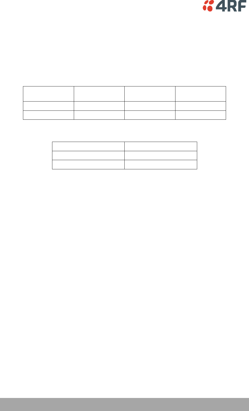
148 | Specifications
Aprisa SR User Manual
12. Specifications
RF Specifications
ETSI Compliant
Frequency Bands
Broadcast Band
Frequency Band
Frequency Tuning
Range
Synthesizer Step
Size
VHF
136 MHz
136-174 MHz
3.125 kHz
UHF
400 MHz
400-470 MHz
6.250 kHz
Channel Sizes
Channel Size
Gross Radio Capacity
12.5 kHz
9.6 kbit/s
25 kHz
19.2 kbit/s
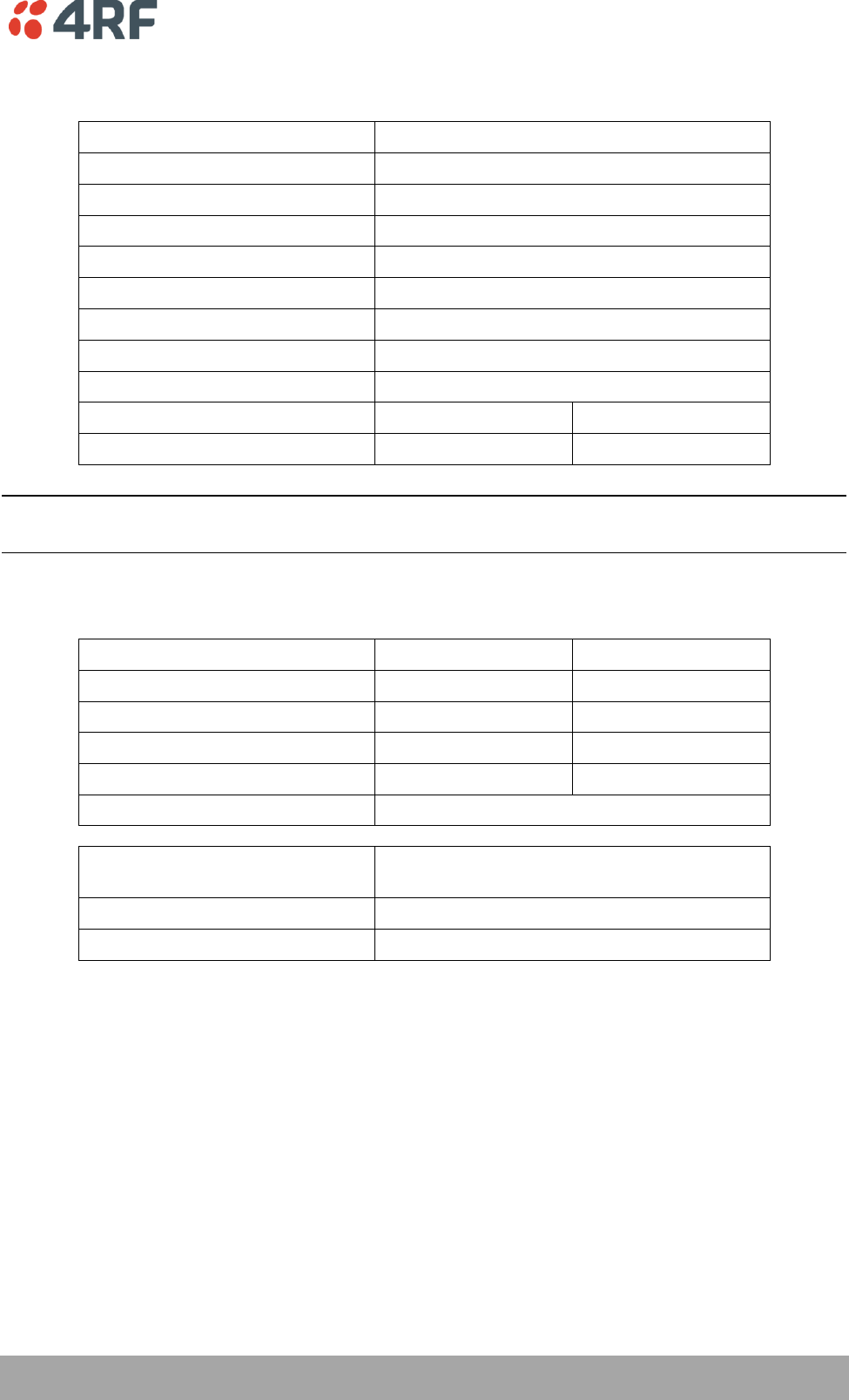
Specifications | 149
Aprisa SR User Manual
Transmitter
Transmit Power output
0.01 to 5.0 W (+10 to +37 dBm, in 1 dB steps)
Transient adjacent channel power
< - 50 dBc
Spurious emissions
< - 37 dBm
Attack time
< 1.5 ms
Release time
< 1.5 ms
Data turnaround time
< 10 ms
Frequency stability
± 1 ppm
Frequency aging
< 1 ppm / annum
Synthesizer lock time
< 1.5 ms (5 MHz step)
12.5 kHz
25 kHz
Adjacent channel power
< - 60 dBc
< - 55 dBc
Note: The Aprisa SR transmitter contains power amplifier protection which allows the antenna to be
disconnected from the antenna port without product damage.
Receiver
12.5 kHz
25 kHz
Receiver sensitivity
BER < 10-2
–117 dBm
–114 dBm
BER < 10-3
–114 dBm
–111 dBm
BER < 10-6
–110 dBm
–107 dBm
Adjacent channel selectivity
> 60 dB
> 45 dB
Co-channel rejection
> –12 dB
Intermodulation response
rejection
> 70 dB
Blocking or desensitization
> 90 dB
Spurious response rejection
> 75 dB
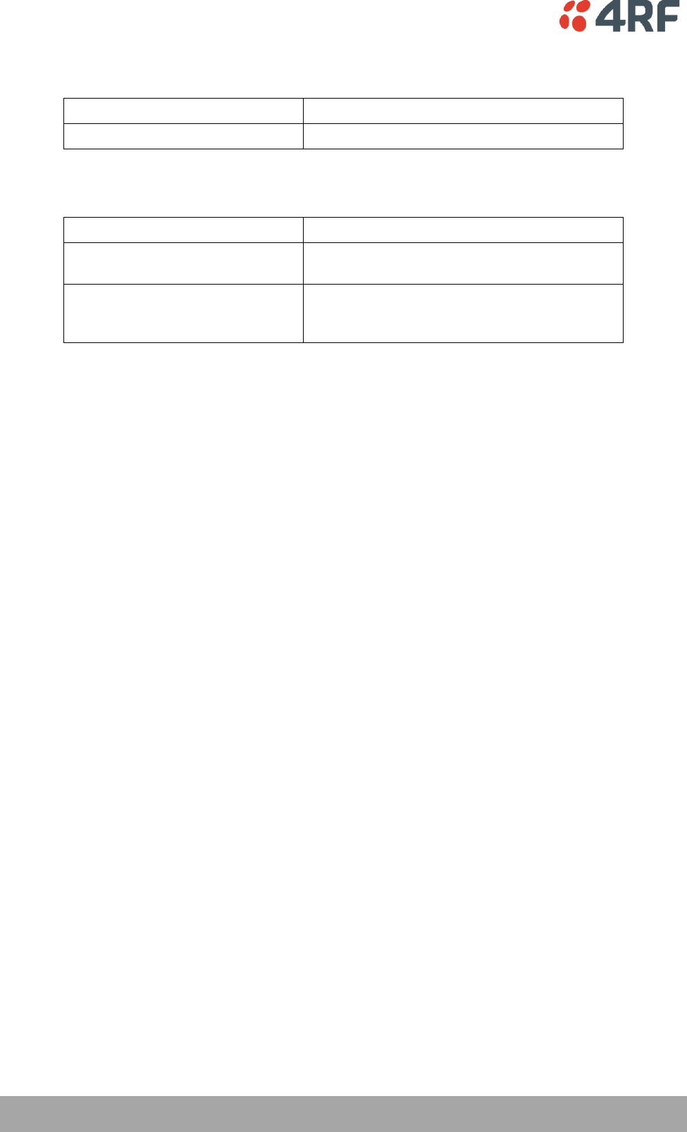
150 | Specifications
Aprisa SR User Manual
Modem
Modulation
4-CPFSK
Forward Error Correction
¾ trellis code
Data Payload Security
Data payload security
CCM* Counter with CBC-MAC
Data encryption
Counter Mode Encryption (CTR) using Advanced
Encryption Standard (AES) 128, 192 or 256
Data authentication
Cipher Block Chaining Message Authentication
Code (CBC-MAC) using Advanced Encryption
Standard (AES) 128, 192 or 256
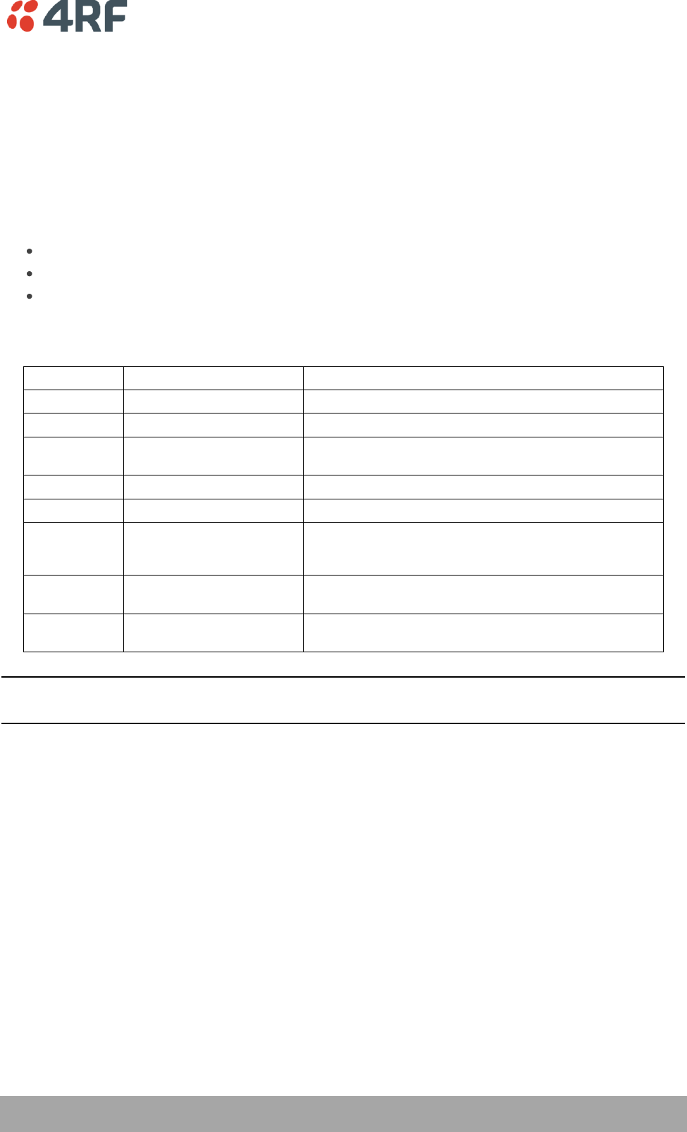
Specifications | 151
Aprisa SR User Manual
Interface Specifications
Ethernet Interface
The Aprisa SR radio features an integrated 10Base-T/100Base-TX layer-2 Ethernet switch.
To simplify network setup, each port supports auto-negotiation and auto-sensing MDI/MDIX. Operators can
select from the following preset modes:
Auto negotiate
10Base-T half or full duplex
100Base-TX half or full duplex
The switch is IEEE 802.3-compatible. It passes VLAN tagged traffic.
General
Interface
RJ-45 x 2 (Integrated 2-port switch)
Cabling
CAT-5 UTP, supports auto MDIX (Standard Ethernet)
Maximum line length
100 metres on cat-5 or better
Bandwidth allocation
The Ethernet capacity maximum is determined by the
available radio link capacity.
Maximum transmission unit
Option setting of 1522 or 1536 octets
Address table size
1024 MAC addresses
Ethernet mode
10Base-T or 100Base-TX
Full duplex or half duplex
(Auto-negotiating and auto-sensing)
Diagnostics
Left Green LED
Off: no Ethernet signal received
On: Ethernet signal received
Right Green LED
Off: Indicates no data traffic present on the interface
Flashing: Indicates data traffic present on the interface
Note: Do not connect Power over Ethernet (PoE) connections to the Aprisa SR Ethernet ports as this will
damage the port.
152 | Specifications
Aprisa SR User Manual
RS-232 Asynchronous Interface
The Aprisa SR radio’s ITU-T V.24 compliant RS-232 interface is configured as a Cisco® pinout DCE. The
interface terminates to a DTE using a straight-through cable or to a DCE with a crossover cable (null
modem).
The interface uses two handshaking control lines between the DTE and the DCE.
General
Interface
ITU-T V.24 / EIA/TIA RS-232E
Interface direction
DCE only
Maximum line length
10 metres
Async
parameters
Standard mode data bits
7 or 8 bits
Standard mode parity
Configurable for None, Even or Odd
Standard mode stop bits
1 or 2 bits
Interface baud rates
300, 1200, 2400, 4800, 9600, 19200, 38400, 57600 and
115200 bit/s
Control signals
DCE to DTE
CTS, RTS, DSR, DTR
Protection Switch Specifications
RF Insertion Loss
< 0.5 dB
Remote Control inputs
Logic 200 ohms pullup to +5 VDC
Specifications | 153
Aprisa SR User Manual
Power Specifications
Power Supply
Aprisa SR Radio
Nominal voltage
+13.8 VDC (negative earth)
Input voltage range
+10 to +30 VDC
Maximum power input
30 W
Connector
Phoenix Contact 4 pin male screw fitting
MC 1.5/ 4-GF-3.5
Aprisa SR Protected Station
Nominal voltage
+13.8 VDC (negative earth)
Input voltage range
+10 to +30 VDC
Maximum power input
35 W
Connector
2x Phoenix Contact 2 pin male screw fitting
MC 1.5/ 2-GF-3.5
Aprisa SR Data Driven Protected Station
Nominal voltage
+13.8 VDC (negative earth)
Input voltage range
+10 to +30 VDC
Maximum power input
35 W
Connector
2x Phoenix Contact 4 pin male screw fitting
MC 1.5/ 2-GF-3.5
Power Consumption
Aprisa SR Radio
Mode
Power Consumption
Transmit / Receive
< 22.5 W for 5W transmit power
< 15.0 W for 1W transmit power
Receive only
< 6 W full Ethernet traffic activity
< 4.5 W no Ethernet traffic activity
Aprisa SR Protected Station and Aprisa SR Data Driven Protected Station
Mode
Power Consumption
Transmit / Receive
< 31 W for 5W transmit power
< 23.5 W for 1W transmit power
Receive only
< 14.5 W full Ethernet traffic activity
< 11.5 W no Ethernet traffic activity
154 | Specifications
Aprisa SR User Manual
Power Dissipation
Aprisa SR Radio
Transmit Power
Power Dissipation
1W transmit power
< 14.0 W
5W transmit power
< 17.5 W
Aprisa SR Protected Station and Aprisa SR Data Driven Protected Station
Transmit Power
Power Dissipation
1W transmit power
< 22.5 W
5W transmit power
< 26.0 W
Specifications | 155
Aprisa SR User Manual
General Specifications
Environmental
Operating temperature range
- 40 to + 70˚ C
Storage temperature range
- 40 to + 80˚ C
Operating humidity
Maximum 95% non-condensing
Acoustic noise emission
No audible noise emission
Mechanical
Aprisa SR Radio
Dimensions
Width 177 mm
Depth 110 mm (126 mm with TNC connector)
Height 41.5 mm
Weight
720 g
Colour
Matt black
Mounting
Wall (2 x M5 screws)
Rack shelf (2 x M4 screws)
DIN rail bracket
Aprisa SR Protected Station
Dimensions
Width 430 mm
Depth 220 mm (incl interconnect cables)
Height 90 mm
Weight
4.46 kg
Colour
Matt black
Mounting
Rack mount (2 x M4 screws)
ETSI compliance
12.5 kHz
25 kHz
Radio
EN 300 113
EN 302 561
EMI / EMC
EN 301 489 Parts 1 & 5
Safety
EN 60950
Environmental
ETS 300 019 Class 3.4

156 | Product End Of Life
Aprisa SR User Manual
13. Product End Of Life
End-of-Life Recycling Programme (WEEE)
The WEEE Directive concerns the recovery, reuse, and recycling of electronic and electrical equipment.
Under the Directive, used equipment must be marked, collected separately, and disposed of properly.
4RF Communications has implemented an end-of-life recycling programme to manage the reuse, recycling,
and recovery of waste in an environmentally safe manner using processes that comply with the WEEE
Directive (EU Waste Electrical and Electronic Equipment 2002/96/EC).
The WEEE Symbol Explained
This symbol appears on Electrical and Electronic Equipment (EEE) as part of the WEEE (Waste EEE)
directive. It means that the EEE may contain hazardous substances and must not be thrown away with
municipal or other waste.
WEEE Must Be Collected Separately
You must not dispose of electrical and electronic waste with municipal and other waste. You must
separate it from other waste and recycling so that it can be easily collected by the proper regional WEEE
collection system in your area.
YOUR ROLE in the Recovery of WEEE
By separately collecting and properly disposing of WEEE, you are helping to reduce the amount of WEEE
that enters the waste stream.
One of the aims of the WEEE directive is to divert EEE away from landfill and encourage recycling.
Recycling EEE means that valuable resources such as metals and other materials (which require energy to
source and manufacture) are not wasted. Also, the pollution associated with accessing new materials and
manufacturing new products is reduced.
EEE Waste Impacts the Environment and Health
Electrical and electronic equipment (EEE) contains hazardous substances which have potential effects on
the environment and human health. If you want environmental information on the Aprisa SR radio, contact
us (on page 13).

Abbreviations | 157
Aprisa SR User Manual
14. Abbreviations
AES Advanced Encryption Standard
AGC Automatic Gain Control
BER Bit Error Rate
CBC Cipher Block Chaining
CCM Counter with CBC-MAC integrity
DCE Data Communications Equipment
DTE Data Radio Equipment
EMC Electro-Magnetic Compatibility
EMI Electro-Magnetic Interference
ESD Electro-Static Discharge
ETSI European Telecommunications Standards
Institute
FW Firmware
HW Hardware
IF Intermediate Frequency
IP Internet Protocol
I/O Input/Output
ISP Internet Service Provider
kbit/s Kilobits per second
kHz Kilohertz
LAN Local Area Network
LED Light Emitting Diode
mA Milliamps
MAC Media Access Control
MAC Message Authentication Code
Mbit/s Megabits per second
MHz Megahertz
MIB Management Information Base
MTBF Mean Time Between Failures
MTTR Mean Time To Repair
ms milliseconds
NMS Network Management System
FAN Field Area Network
PC Personal Computer
PCA Printed Circuit Assembly
PLL Phase Locked Loop
ppm Parts Per Million
PMR Public Mobile Radio
RF Radio Frequency
RoHS Restriction of Hazardous Substances
RSSI Received Signal Strength Indication
RX Receiver
SNMP Simple Network Management Protocol
SNR Signal to Noise Ratio
SWR Standing Wave Ratio
TCP/IP Transmission Control Protocol/Internet
Protocol
TCXO Temperature Compensated Crystal Oscillator
TFTP Trivial File Transfer Protocol
TMR Trunk Mobile Radio
TX Transmitter
UTP Unshielded Twisted Pair
VAC Volts AC
VCO Voltage Controlled Oscillator
VDC Volts DC
WEEE Waste Electrical and Electronic Equipment

158 | Index
Aprisa SR User Manual
15. Index
A
access rights 101
accessory kit 14
antennas
aligning 138
installing 53
selection and siting 44
siting 46
attenuators 43
B
bench setup 43
C
cabling
accessory kit 14
coaxial feeder 43, 47
CD contents 14
E
earthing 43, 47, 49
environmental requirements 48
F
feeder cables 47
front panel
connections 24
test mode 26
H
hardware
accessory kit 14
installing 53
humidity 48
I
in-service commissioning 137
interface connections 142
Ethernet 142
RS-232 Serial 143
J
Java
requirement for 14
L
lightning protection 49
linking system plan 47
logging in
SuperVisor 63
logging out
SuperVisor 64
M
maintenance summary 108
mounting kit 14
O
operating temperature 48
P
passwords
changing 103
path planning 44
path propagation calculator 44
pinouts
Ethernet 142
RS-232 Serial 143
power supply 48
R
radio
earthing 43, 49
logging into 63
logging out 64
operating temperature 48
rebooting 113
storage temperature 48
rebooting the radio 113
RS-232
serial data 89
RS-232 Serial interface 88
interface connections for 143

Index | 159
Aprisa SR User Manual
port settings for 89
RSSI
aligning the antennas 138
test mode 26
S
security
settings 104, 107, 124, 128, 129
summary 100
security users
user privileges 101
SuperVisor
logging into 63
logging out 64
PC settings for 59
T
temperature 48
tools 50
U
users
adding 102
changing passwords 103
deleting 103
user details 101
user privilege 102
W
WEEE 156