8devices JLP Broadband Digital Transmission System User Manual
8devices Broadband Digital Transmission System
UserManual.wiki
>
8devices
>
JLP User Manual
User manual
Navigation menu
Upload a User Manual
Namespaces
Wiki Guide
HTML
PDF
Info
Views
User Manual
Discussion / Help
Navigation

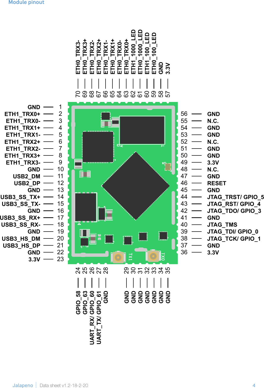
![5 Jalapeno Data sheet v1.2-18-2-20Pin Name GPIO function selectCongurable functionVoltage (V) Type Description1 GND - - - - Ground connection2 ETH1_TRX0+ - - - AI, AO 1000 Base-T output positive3 ETH1_TRX0- - - - AI, AO 1000 Base-T output negative4 ETH1_TRX1+ - - - AI, AO 1000 Base-T output positive5 ETH1_TRX1- - - - AI, AO 1000 Base-T output negative6 ETH1_TRX2+ - - - AI, AO 1000 Base-T output positive7 ETH1_TRX2- - - - AI, AO 1000 Base-T output negative8 ETH1_TRX3+ - - - AI, AO 1000 Base-T output positive9 ETH1_TRX3- - - - AI, AO 1000 Base-T output negative10 GND - - - - Ground connection11 USB2_DM - - - AI, AO USB 2.0 data negative12 USB2_DP - - - AI, AO USB 2.0 data positive13 GND - - - - Ground connection14 USB3_SS_TX+ - - - AO USB 3.0 SuperSpeed transmitter positive15 USB3_SS_TX- - - - AO USB 3.0 SuperSpeed transmitter negative16 GND - - - - Ground connection17 USB3_SS_RX+ - - - AI USB 3.0 SuperSpeed receiver positive18 USB3_SS_RX- - - - AI USB 3.0 SuperSpeed receiver negative19 GND - - - - Ground connection20 USB3_HS_DM - - - AI, AO USB 2.0 data negative21 USB3_HS_DP - - - AI, AO USB 2.0 data positive22 GND - - - - Ground connection23 3.3V - - - PI 3.3V power supply24 GPIO58 0 GPIO 3.3 - -2 LED[2] 3.3 O -5 smart_ant6 3.3 IO -25 GPIO63 0 GPIO 3.3 - -5 Audio_txd[1] 3.3 O Audio transmit data6 Audio_rxd 3.3 I Audio receive data26 UART_RX/GPIO60 0 GPIO 3.3 - -2 blsp_uart0_rxd(1) 3.3 I UART RX4 smart_ant4 3.3 IO -5 LED[0] 3.3 O -6 audio_txbclk 3.3 IO Audio transmit bit block7 audio_rxbclk 3.3 IO Audio receive bit block27 UART_TX/GPIO61 0 GPIO 3.3 - -2 blsp_uart0_txd 3.3 O UART TX4 smart_ant5 3.3 IO -5 audio_txfsync 3.3 IO Audio transmit frame sync6 audio_rxfsync 3.3 IO Audio receiver frame sync7 LED[1] 3.3 O -boot_cong(14) 3.3 I -](https://usermanual.wiki/8devices/JLP/User-Guide-4034275-Page-5.png)