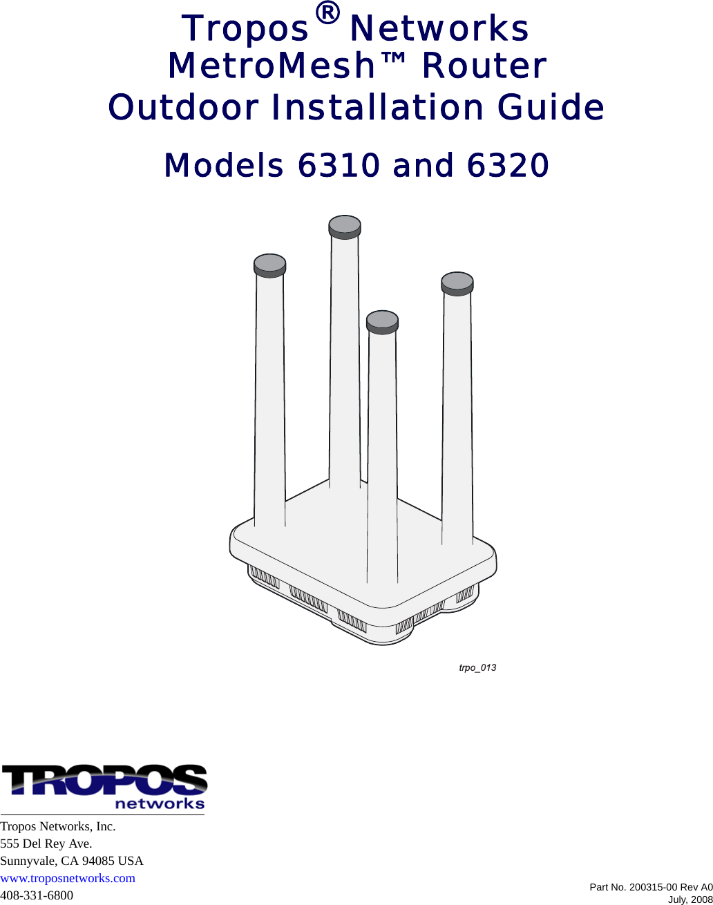
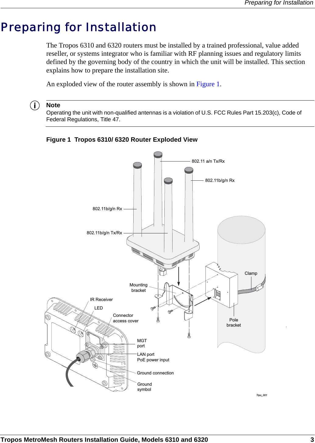
ABB Enterprise Software 2411 2.4 GHz 802.11n High Power Mini-PCI Card User Manual 6310 6320 Guide

Tropos Networks, Inc. 2.4 GHz 802.11n High Power Mini-PCI Card 6310 6320 Guide

Users Manual

Part No. 200315-00 Rev A0July, 2008Tropos® Networks MetroMesh™ RouterOutdoor Installation GuideModels 6310 and 6320trpo_013Tropos Networks, Inc.555 Del Rey Ave.Sunnyvale, CA 94085 USAwww.troposnetworks.com408-331-6800
Tropos MetroMesh Routers Installation Guide, Models 6310 and 6320 iiCopyright Notice©2003-2008 Tropos Networks, Inc. All rights reserved. Tropos and PWRP are registered trademarks of Tropos Networks, Inc. Tropos Networks, MetroMesh, AMCE, TMCX, SABRE, CMDP, MESM and Metro-Scale Mesh Networking Defined are trademarks of Tropos Networks, Inc. Loctite is a registered trademark of Loctite Corporation, USA. All other brand or product names are trademarks or registered trademarks of their respective holder(s).Information contained herein is subject to change without notice. The only warranties for Tropos products and services are set forth in the express warranty statements accompanying such products and services. Nothing herein should be construed as constituting an additional warranty. Tropos shall not be liable for technical or editorial errors or omissions contained herein.This product includes technology protected by U.S. Patents 6,704,301; 6,965,575; 7,016,328; 7,031,293; and 7,058,021.FCC Notice to Users and OperatorsThis device complies with Part 15 of the FCC Rules. Operation is subject to the following two conditions: (1) this device may not cause harmful interference, and (2) this device must accept any interference received, including interference that may cause undesired operation.This equipment has been tested and found to comply with the limits for a Class B digital device, pursuant to Part 15 of the FCC Rules. These limits are designed to provide reasonable protection against harmful interference when the equipment is operated in a commercial environment. This equipment generates, uses, and can radiate radio frequency energy and, if not installed and used in accordance with the instruction manual, may cause harmful interference to radio communications. Operation of this equipment in a residential area is likely to cause harmful interference, in which case the user will be required to correct the interference at his own expense. If this equipment does cause interference to radio or television reception, which can be determined by turning the equipment off and on, the user is encouraged to correct the interference by using one of the following measures:Reorient or relocate the receiving antenna. Increase separation between the equipment and receiver. Connect the equipment to an outlet on a circuit different from that to which the receiver is connected. Consult the dealer or an experienced radio/TV technician.This Part 15 radio device operates on a non-interference basis with other devices operating at this frequency. Any changes or modification to said product not expressly approved by Tropos Networks could void the user's authority to operate this device.Industry CanadaNotice to users and operators:This Class B digital apparatus meets all requirements of the Canadian Interference Causing Equipment Regulations. Operation is subject to the following two conditions: (1) this device may not cause harmful interference, and (2) this device must accept any interference received, including interference that may cause undesired operation.Cet appareillage numérique de la classe B répond à toutes les exigences de l’interférence canadienne causant des réglements d’équipement. L’opération est sujette aux deux conditions suivantes : (1) cet dispositif peut ne pas causer l'interférence nocive, et (2) ce dispositif doit accepter n’importe quelle interférence reçue, y compris l'interférence qui peut causer l’opération peu désirée.WarningIt is illegal to modify the construction of this product. Modifying the operating frequency or enhancing the transmit output power through the use of external amplifiers or other equipment is specifically disallowed by the “Telecommunications Act.”
Tropos MetroMesh Routers Installation Guide, Models 6310 and 6320 iiiWarningThis device is for outdoor or indoor use with conditions that no harmful interference to authorized radio stations results from the operation of this device. This device shall not influence aircraft security and/or interfere with legal communications as defined in the “Telecommunications Act.” If this device is found to cause interference, the operator of this equipment shall cease operating this device immediately until no interference is achieved. European Union WEEE NoticeIt is important for users of this equipment to participate in reuse, recycling, and other forms of recovery. The potential effects on the environment and human health as a result of the presence of hazardous substances in electrical and electronic equipment are a waste of natural resources and cause pollution.For EU member countries, this symbol means: Do not dispose of this equipment as unsorted municipal waste. This equipment must be collected separately. The return and collection of this product has not been defined at this time, please contact Tropos Networks for return and/or collection.
Tropos MetroMesh Routers Installation Guide, Models 6310 and 6320 ivEuropean Community Language Versions of Informal Statement for Inclusion in User Information The following statements are in accordance with Article 6.3 of Directive 1999/5/EC.532053205320532053205320532053205320532053205320532053206320631063206310632063106320631063206310632063106320631063206310632063106320631063206310632063106320631063206310
Tropos MetroMesh Routers Installation Guide, Models 6310 and 6320 vSTOP!! STOP!! STOP!! STOP!!READ THIS FIRST!Important Safety InstructionsThe exclamation point within an equilateral triangle is intended to alert the user to the presence of important operating and maintenance (servicing) instructions in the literature accompanying the product.The lightning flash with an arrowhead symbol within an equilateral triangle is intended to alert the user to the presence of uninsulated “dangerous voltage” within the product’s enclosure that may be of sufficient magnitude to constitute a risk of electric shock to persons.CautionRead these instructions.Keep these instructions.Heed all warnings.Follow all instructions. Do not defeat the safety purpose of the grounding.Only use attachments/accessories specified by the manufacturer.Refer all servicing to qualified service personnel. Servicing is required when the apparatus has been damage in any way, such as power-supply cord or plug is damaged, liquid has been spilled on objects have fallen into the apparatus, the apparatus has been exposed to rain or moisture, does not operate normally, or has been dropped.
Tropos MetroMesh Routers Installation Guide, Models 6310 and 6320 viWarningRisk of personal injury or death when installing this device!There is a risk of personal injury or death if the router antennas come near electric power lines. Carefully read and follow all instructions in this manual. By nature of the installation, you may be exposed to hazardous environments and high voltage. Use caution when installing the outdoor system.This apparatus must be connected to earth ground. Do not open the unit — risk of electric shock inside.Risque d'électrocution. Ne pas ouvrir l'unité.CautionYou are cautioned that any change or modification not expressly approved in this manual could void your authority to operate this equipment.Les changements et modifications, non expressément approuvés dans le présent manuel, peuvent entraîner une interdiction d'utiliser cet appareil pour l'utilisateur.ServiceThere are no user-serviceable parts inside. All service must be performed by qualified personnel.Vous ne devez pas réparer les pièces se trouvant à l'intérieur de l'appareil. Les réparations doivent être effectuées uniquement par du personnel qualifié.The Tropos 6310 and 6320 routers are installed in wet, outdoor locations. Make sure closure caps are installed and all cable connections are securely fastened and waterproofed.Surfaces may become hot. Use caution when accessing the Tropos 6310 and 6320 routers.
Tropos MetroMesh Routers Installation Guide, Models 6310 and 6320 viiContents1 Installing the Router  . . . . . . . . . . . . . . . . . . . . . . . . . . . . . . . . . . . . . . . . . .  1Product Summary. . . . . . . . . . . . . . . . . . . . . . . . . . . . . . . . . . . . . . . . . . . . . .  2Tropos 6310 Router  . . . . . . . . . . . . . . . . . . . . . . . . . . . . . . . . . . . . . . . . . .  2Tropos 6320 Router  . . . . . . . . . . . . . . . . . . . . . . . . . . . . . . . . . . . . . . . . . .  2Preparing for Installation  . . . . . . . . . . . . . . . . . . . . . . . . . . . . . . . . . . . . . . . .  3Installation Hardware and Tools . . . . . . . . . . . . . . . . . . . . . . . . . . . . . . . . .  4Site Planning . . . . . . . . . . . . . . . . . . . . . . . . . . . . . . . . . . . . . . . . . . . . . . . .  4Location Guidelines. . . . . . . . . . . . . . . . . . . . . . . . . . . . . . . . . . . . . . . . . . .  5Site Surveys  . . . . . . . . . . . . . . . . . . . . . . . . . . . . . . . . . . . . . . . . . . . . . . . .  5Power Source . . . . . . . . . . . . . . . . . . . . . . . . . . . . . . . . . . . . . . . . . . . . . . .  6Safety  . . . . . . . . . . . . . . . . . . . . . . . . . . . . . . . . . . . . . . . . . . . . . . . . . . . . .  6Mounting Strategies . . . . . . . . . . . . . . . . . . . . . . . . . . . . . . . . . . . . . . . . . . . .  6Proper Use of Clamps . . . . . . . . . . . . . . . . . . . . . . . . . . . . . . . . . . . . . . . . . .  8Pole, Tower, and Streetlight Mounting Instructions . . . . . . . . . . . . . . . . . . . .  9Metal Pole Mounting . . . . . . . . . . . . . . . . . . . . . . . . . . . . . . . . . . . . . . . . .  10Wood Pole Mounting. . . . . . . . . . . . . . . . . . . . . . . . . . . . . . . . . . . . . . . . .  13Wood Brace Mounting. . . . . . . . . . . . . . . . . . . . . . . . . . . . . . . . . . . . . . . .  15Tower Mounting. . . . . . . . . . . . . . . . . . . . . . . . . . . . . . . . . . . . . . . . . . . . .  16Streetlight Mounting  . . . . . . . . . . . . . . . . . . . . . . . . . . . . . . . . . . . . . . . . .  17Connecting Data Cables  . . . . . . . . . . . . . . . . . . . . . . . . . . . . . . . . . . . . . . .  18Grounding the Router. . . . . . . . . . . . . . . . . . . . . . . . . . . . . . . . . . . . . . . . . .  21Grounding the Data Protection Device . . . . . . . . . . . . . . . . . . . . . . . . . . .  22Safety and Servicing Information . . . . . . . . . . . . . . . . . . . . . . . . . . . . . . . . .  23Safety Guidelines  . . . . . . . . . . . . . . . . . . . . . . . . . . . . . . . . . . . . . . . . . . .  23Servicing the Router . . . . . . . . . . . . . . . . . . . . . . . . . . . . . . . . . . . . . . . . .  232 Power Consumption  . . . . . . . . . . . . . . . . . . . . . . . . . . . . . . . . . . . . . . . . .  243 Product Specifications  . . . . . . . . . . . . . . . . . . . . . . . . . . . . . . . . . . . . . . .  254 Antenna Information  . . . . . . . . . . . . . . . . . . . . . . . . . . . . . . . . . . . . . . . . .  315 Installation Accessories . . . . . . . . . . . . . . . . . . . . . . . . . . . . . . . . . . . . . .  34
Tropos MetroMesh Routers Installation Guide, Models 6310 and 6320 viii6 Wind Loading Considerations  . . . . . . . . . . . . . . . . . . . . . . . . . . . . . . . . .  35Abbreviations   . . . . . . . . . . . . . . . . . . . . . . . . . . . . . . . . . . . . . . . . . . . . . .  36Index . . . . . . . . . . . . . . . . . . . . . . . . . . . . . . . . . . . . . . . . . . . . . . . . . . . . . .  39
Tropos MetroMesh Routers Installation Guide, Models 6310 and 6320 ixList of FiguresTropos 6310/ 6320 Router Exploded View  . . . . . . . . . . . . . . . . . . . . . . .  3Example Mounting Location - Antennas Facing Upward   . . . . . . . . . . . .  7Proper Use of the Clamp . . . . . . . . . . . . . . . . . . . . . . . . . . . . . . . . . . . . .  8Metal Pole Mounting  . . . . . . . . . . . . . . . . . . . . . . . . . . . . . . . . . . . . . . .  10Placing the Router on the Mounting Assembly  . . . . . . . . . . . . . . . . . . .  12Wood Pole Mounting . . . . . . . . . . . . . . . . . . . . . . . . . . . . . . . . . . . . . . .  13Wood Brace Mounting Option  . . . . . . . . . . . . . . . . . . . . . . . . . . . . . . . .  15Tower Mounting . . . . . . . . . . . . . . . . . . . . . . . . . . . . . . . . . . . . . . . . . . .  16Streetlight Mounting   . . . . . . . . . . . . . . . . . . . . . . . . . . . . . . . . . . . . . . .  17Routing the Data/Power Cable to the Router  . . . . . . . . . . . . . . . . . . . .  19Data Port Connection  . . . . . . . . . . . . . . . . . . . . . . . . . . . . . . . . . . . . . .  20Grounding Arrangement  . . . . . . . . . . . . . . . . . . . . . . . . . . . . . . . . . . . .  21Grounding the Indoor Network Protection Unit  . . . . . . . . . . . . . . . . . . .  226310/ 6320 Power Consumption . . . . . . . . . . . . . . . . . . . . . . . . . . . . . .  242.4 GHz Antenna Patterns   . . . . . . . . . . . . . . . . . . . . . . . . . . . . . . . . . .  325 GHz Antenna Patterns  . . . . . . . . . . . . . . . . . . . . . . . . . . . . . . . . . . . .  33
Tropos MetroMesh Routers Installation Guide, Models 6310 and 6320 xList of TablesTropos 6310 Router Models  . . . . . . . . . . . . . . . . . . . . . . . . . . . . . . . . . . . . .  2Tropos 6320 Router Models  . . . . . . . . . . . . . . . . . . . . . . . . . . . . . . . . . . . . .  2Physical Specifications  . . . . . . . . . . . . . . . . . . . . . . . . . . . . . . . . . . . . . . . .  25Interfaces . . . . . . . . . . . . . . . . . . . . . . . . . . . . . . . . . . . . . . . . . . . . . . . . . . .  27Power Options / Consumption . . . . . . . . . . . . . . . . . . . . . . . . . . . . . . . . . . .  30Certifications, Other . . . . . . . . . . . . . . . . . . . . . . . . . . . . . . . . . . . . . . . . . . .  30Installation Accessories . . . . . . . . . . . . . . . . . . . . . . . . . . . . . . . . . . . . . . . .  34Abbreviations . . . . . . . . . . . . . . . . . . . . . . . . . . . . . . . . . . . . . . . . . . . . . . . .  36
Tropos MetroMesh Routers Installation Guide, Models 6310 and 6320 11Installing the RouterThis guide explains how to install the Tropos® 6310 and 6320 MetroMesh™ routers safely and is intended for trained technical professionals. This chapter covers the following topics:“Product Summary” on page 2“Preparing for Installation” on page 3“Mounting Strategies” on page 6“Proper Use of Clamps” on page 8“Pole, Tower, and Streetlight Mounting Instructions” on page 9“Connecting Data Cables” on page 18“Grounding the Router” on page 21“Safety and Servicing Information” on page 23
Product SummaryTropos MetroMesh Routers Installation Guide, Models 6310 and 6320 2Product SummaryThis document contains installation instructions for the following products:Tropos 6310 RouterTropos 6320 RouterTropos 6310 RouterThe Tropos 6310 router has the following characteristics:802.11b/g/n band, 2400-2483 MHzSupport for 802.11b/g/n clientsPoE power input 20-60 Vdc; 100-277 VAC with external accessoryLAN and Management 10/100BaseT Ethernet ports, auto-sensingTable 1 lists the Tropos 6310 router models.Tropos 6320 RouterThe Tropos 6320 router has the following characteristics: 802.11a/b/g/n dual band, 2400-2500 MHz/5470-5825 MHzSupport for 802.11a/b/g/n clientsPoE power input 20-60 Vdc; 100-277 VAC with external accessoryLAN and Management 10/100BaseT Ethernet ports, auto-sensingTable 1 lists the Tropos 6320 router models.Table 1  Tropos 6310 Router ModelsModel Description63103030 6310: 2.4 GHz, PoE power (FCC)63102530 6310: 2.4 GHz, PoE power (ETSI)Table 2  Tropos 6320 Router ModelsModel Description63203030 6320: 2.4 and 5.8 GHz, PoE power (FCC)63202530 6320: 2.4 and 5.4 GHz, PoE power (ETSI)
Preparing for InstallationTropos MetroMesh Routers Installation Guide, Models 6310 and 6320 3Preparing for InstallationThe Tropos 6310 and 6320 routers must be installed by a trained professional, value added reseller, or systems integrator who is familiar with RF planning issues and regulatory limits defined by the governing body of the country in which the unit will be installed. This section explains how to prepare the installation site.An exploded view of the router assembly is shown in Figure 1. NoteOperating the unit with non-qualified antennas is a violation of U.S. FCC Rules Part 15.203(c), Code of Federal Regulations, Title 47. Figure 1  Tropos 6310/ 6320 Router Exploded ViewTrpo_001ClampPolebracketGroundsymbolLAN portPoE power inputMGTport802.11b/g/n Rx802.11 a/n Tx/Rx802.11b/g/n Rx802.11b/g/n Tx/RxIR ReceiverLEDMountingbracketConnectoraccess coverGround connection
Preparing for InstallationTropos MetroMesh Routers Installation Guide, Models 6310 and 6320 4Installation Hardware and ToolsThe following installation accessories are included in the shipping package:One pole bracketOne 4-inch diameter clampOne 6-inch diameter clampFive 5/16-inch #10-32 stainless steel hex head machine screwsYou must supply the following tools:Level5/16-inch nut driver1/4-inch flat blade screwdriverTower mounting only: stainless or galvanized steel channel stock and 1/2-inch or 5/8-inch nuts, bolts, and washers to connect to the tower arm.Wood pole mounting only: one 1/4-inch diameter, 3 1/2-inch long lag boltSite PlanningTo ensure safe and durable wiring, router installation must follow appropriate electrical and building codes. Follow the National Electrical Code (NEC) requirements, unless local codes in your area take precedence over the NEC code. The following distance limits apply to installations that have 10/100 Base-T Category 5 network cables attached to the routers:300 feet maximum between devices for 100BaseT operation500 feet maximum for 10BaseT operation. The Ethernet duplex and speed setting is configurable.NoteNational Electrical Codes (NEC) Article 800 requires the use of Agency Listed (UL/CSA/TUV) Building Entrance Protector for all power and data communications cables entering a building. The NEC intends by Article 800 to protect the building and occupants from fires caused by transient voltage and current surges. NoteEthernet data cable installations having lengths greater than 140 feet in the outdoor environment must use a UL497 approved (UL/CSA/TUV Listed) primary protection device at the building entrance. Ethernet data cable installations having lengths less than 140 feet in the outdoor environment may use a UL497A (UL/CSA/TUV Listed) secondary protection device at the building entrance. Tropos Data Protection Device and Network Protection Units are UL497A secondary protection devices.
Preparing for InstallationTropos MetroMesh Routers Installation Guide, Models 6310 and 6320 5Location GuidelinesTropos routers are radio devices and therefore susceptible to interference that can reduce throughput and range. Follow these guidelines to ensure the best performance:Install the unit in an area where trees, buildings, and large steel structures do not obstruct radio signals to and from the antenna. Direct line-of-sight operation is best. Install the unit away from microwave ovens or other devices operating in the 2.4 GHz, 4.9 GHZ, or 5.8 GHz frequency range. Install the unit away from other possible sources of 802.11a/b/g/n interference, such as cordless phones, home spy cameras, frequency hopping (FHSS) and DSSS LAN transceivers (non-802.11), electronic news gathering video links, radars, amateur radios, land mobile radio services, local government sites (such as law enforcement), fixed microwave services, local TV transmission and private fixed point transmitters.Site SurveysDue to variations in component configuration, placement, and physical environment, each installation is unique. Before installing routers, perform a site survey to determine the optimum placement of units for maximum range, coverage, and network performance. Consider the following factors when performing a site survey:Data rates—Sensitivity and range are inversely proportional to data bit rates. The maximum radio range is achieved at the lowest workable data rate. A decrease in receiver threshold sensitivity occurs as radio data rate increases. Antenna orientation—Proper antenna orientation is a critical factor in maximizing radio range. As a general rule, range increases in proportion to gain and antenna height measured from the ground. Physical environment—Clear or open areas provide better radio range than closed or filled areas. The less cluttered the operating environment, the greater the range. Obstructions—A physical obstruction, such as a building or tree, can block or hinder communication. Avoid locating antennas in a location where there is an obstruction between sending and receiving devices. Building materials—Radio penetration is influenced by the building material used in construction. For example, drywall construction permits greater range than concrete blocks.
Mounting StrategiesTropos MetroMesh Routers Installation Guide, Models 6310 and 6320 6Power SourceThe Tropos 6310 and 6320 routers are powered by power over Ethernet (PoE) input:PoE (20-60Vdc)100-277 VAC with external accessoryCautionTropos 6310 and 6320 routers use proprietary PoE. The routers are not 802.3af compliant.SafetyInstalling the routers can pose a serious hazard. Be sure to take precautions to avoid the following:Exposure to high voltage lines during installationFalls when working at heights or with laddersInjuries from dropping tools and equipmentContact with AC wiring Mounting StrategiesWhen choosing mounting locations, consider the available mounting structures and antenna clearance. The router should always be mounted with the top of the unit horizontal and level and with the antennas facing upward.It is usually best to attach ground and data cables to the router prior to mounting. Before mounting the router, review the wiring instructions in “Grounding the Router” on page 21 and “Connecting Data Cables” on page 18 to determine the best strategy for the selected location.NoteTo eliminate potential interference from the mounting structure, the router should be mounted with at least 4 feet of clearance around the antennas.
Mounting StrategiesTropos MetroMesh Routers Installation Guide, Models 6310 and 6320 7Acceptable options for mounting on a streetlight are shown in Figure 2. In each case the router is mounted to assure clearance for the antennas above the height of the streetlight.Figure 2  Example Mounting Location - Antennas Facing Upwardtrpo_002Antennas clear of obstructionAntennas clearof obstruction
Proper Use of ClampsTropos MetroMesh Routers Installation Guide, Models 6310 and 6320 8Proper Use of ClampsThe mounting assembly contains a clamp to secure the router to the mounting structure. Figure 3 illustrates the proper use of the clamp. The clamp must be routed through a slot in the pole bracket as shown in the figure, and then attached to the pole and tightened.The pole bracket should be leveled before it is secured to the pole.Figure 3  Proper Use of the Clamptrpo_003ClampPolebracketMountingbracketBand goesbehindinner tabs
Pole, Tower, and Streetlight Mounting InstructionsTropos MetroMesh Routers Installation Guide, Models 6310 and 6320 9Pole, Tower, and Streetlight Mounting InstructionsThis section explains how to mount the router on a pole, tower, or streetlight. It is best to mount the router to aluminum or galvanized steel structures. The mounting brackets are designed to pierce any oxidation layers that are on the outside of the pole, thereby assuring good quality connection to the grounded structure.Due to potential antenna obstruction issues, the router is not designed to be directly mounted on a building wall. If it is necessary to mount the router on a wall, follow the instructions for mounting on a wooden pole (“Wood Pole Mounting” on page 13), and attempt to mount the router with maximum possible clearance around the antennas.NoteThe router should always be mounted with the top of the router horizontal and level and with the antennas facing upward.NoteIt is best to attach ground and data cables to the router before sliding the router into the mounting bracket, as explained in this section. Before mounting the router, review the wiring instructions in “Grounding the Router” on page 21 and “Connecting Data Cables” on page 18 to determine the best strategy for the selected location.NoteMounting to wood, concrete, or painted poles may require primary grounding for the unit. Check the national electrical codes in your area for specific rules.
Pole, Tower, and Streetlight Mounting InstructionsTropos MetroMesh Routers Installation Guide, Models 6310 and 6320 10Metal Pole MountingFigure 4 illustrates proper mounting for an outdoor metal pole. NoteAntennas must be clear of obstruction.Figure 4  Metal Pole MountingClampPolebracketWireless router
Pole, Tower, and Streetlight Mounting InstructionsTropos MetroMesh Routers Installation Guide, Models 6310 and 6320 11Mount the router on a metal pole1. Select a mounting location. You can attach the router to any pipe or pole with diameter between 1 inch and 10 inches.2. Slip the flat portion of the clamp under the inner slot of the pole bracket. 3. Use the clamp to attach the pole bracket to the pole, making sure that it is level. Depending upon the diameter of the pole, you may need to use a single small clamp, single large clamp, or pair of large clamps joined together to reach around the pole. 4. Attach the mounting bracket of the router to the pole bracket with two 5/16-inch machine screws (refer to Figure 4 for the correct orientation):Insert one screw through the hole at the top of the mounting bracket to the hole at the top of the pole bracket.Insert the other screw through the curved slot track in the mounting bracket to the hole in the middle of the pole bracket just above the clamp slot.5. Level the mounting bracket by rotating the unit along the curved slot tracks. Tighten the screws.6. Place the upright router onto the top of the mounting bracket, as shown in Figure 5. Secure the mounting bracket to the router by attaching two 5/16-inch machine screws through the holes in the mounting bracket tabs to corresponding holes on the bottom of the router.
Pole, Tower, and Streetlight Mounting InstructionsTropos MetroMesh Routers Installation Guide, Models 6310 and 6320 12Figure 5  Placing the Router on the Mounting AssemblyTo continue installing the router, see “Connecting Data Cables” on page 18.trpo_015
Pole, Tower, and Streetlight Mounting InstructionsTropos MetroMesh Routers Installation Guide, Models 6310 and 6320 13Wood Pole MountingFigure 6 illustrates proper mounting for an outdoor wood pole.NoteAntennas must be clear of obstruction.Figure 6  Wood Pole Mountingtrpo_005PolebracketWireless Router
Pole, Tower, and Streetlight Mounting InstructionsTropos MetroMesh Routers Installation Guide, Models 6310 and 6320 14Mount the router on a wood pole1. Select a mounting location. You can attach the router to any outdoor wood pole of diameter at least 1 inch. 2. Attach the pole bracket to the pole by threading a 1/4-inch bolt through the hole in the clamp slot to the pole. The bolt should be at least 3 1/2 inches in length. Make sure that the bracket is level. 3. Attach the mounting bracket of the router to the pole bracket with two 5/16-inch machine screws (refer to Figure 4 for the correct orientation):Insert one screw through the hole at the top of the mounting bracket to the hole at the top of the pole bracket.Insert the other screw through the curved slot track in the mounting bracket to the hole in the middle of the pole bracket just above the clamp slot.4. Level the mounting bracket by rotating the unit along the curved slot tracks. Tighten the screws.5. Place the upright router onto the top of the mounting bracket, as shown in Figure 5 on page 12. Secure the mounting bracket to the router by attaching two 5/16-inch machine screws through the holes in the mounting bracket tabs to corresponding holes on the bottom of the router.To continue installing the router, see “Connecting Data Cables” on page 18.
Pole, Tower, and Streetlight Mounting InstructionsTropos MetroMesh Routers Installation Guide, Models 6310 and 6320 15Wood Brace MountingYou can mount the pole bracket directly on a wood brace without using clamps, as shown in Figure 7.Figure 7  Wood Brace Mounting OptionMount the router on a wood pole1. Select a mounting location. You can attach the router to any wood brace. 2. Attach the pole bracket to the wood brace with two 1/4-inch lag bolts that are at least 3 1/2 inches in length, making sure that the wood brace is level. 3. Attach the mounting bracket of the router to the pole bracket with two 5/16-inch machine screws (refer to Figure 4 for the correct orientation):Insert one screw through the hole at the top of the mounting bracket to the hole at the top of the pole bracket.Insert the other screw through the curved slot track in the mounting bracket to the hole in the middle of the pole bracket just above the clamp slot.4. Level the mounting bracket by rotating the unit along the curved slot tracks. Tighten the screws.trpo_006Wood brace1/4" lag bolt3-1/2" minimum
Pole, Tower, and Streetlight Mounting InstructionsTropos MetroMesh Routers Installation Guide, Models 6310 and 6320 165. Place the upright router onto the top of the mounting bracket, as shown in Figure 5 on page 12. Secure the mounting bracket to the router by attaching two 5/16-inch machine screws through the holes in the mounting bracket tabs to corresponding holes on the bottom of the router.To continue installing the router, see “Connecting Data Cables” on page 18.Tower MountingYou can mount the router on an outdoor tower. NoteAt the antenna level, the router must be free from metal obstruction within a 4-foot radius (Figure 8).Figure 8  Tower MountingMount the Tropos router on a tower1. Remove the pole bracket from the mounting bracket, if they are attached.2. Make a tower bracket by attaching the mounting bracket directly to any stainless steel or galvanized steel channel stock. 3. Attach the mounting bracket to the tower arm so that the top of the shield is horizontal and level.4. Tighten the mounting bolts.5. Place the upright router onto the top of the mounting bracket, as shown in Figure 5 on page 12. Secure the mounting bracket to the router by attaching two 5/16-inch machine screws through the holes in the mounting bracket tabs to corresponding holes on the bottom of the router.To continue installing the router, see “Connecting Data Cables” on page 18.trp0 0074'Brackets not includedChannel stock
Pole, Tower, and Streetlight Mounting InstructionsTropos MetroMesh Routers Installation Guide, Models 6310 and 6320 17Streetlight MountingYou can mount the router on the horizontal or angled arm of a streetlight. Figure 9 shows a typical streetlight mounting installation.Figure 9  Streetlight MountingMount the router on a streetlight1. Select a mounting location. You can attach the router to any streetlight arm with diameter 1” to 10”. 2. Slip the flat portion of the clamp under the inner slot of the pole bracket. 3. Use the clamp to attach the pole bracket to the arm, making sure that it is level. Depending upon the diameter of the arm, you may need to use a single small clamp, single large clamp, or pair of large clamps joined together. trpo_00PolebracketRouter
Connecting Data CablesTropos MetroMesh Routers Installation Guide, Models 6310 and 6320 184. Attach the mounting bracket of the router to the pole bracket with two 5/16-inch machine screws (refer to Figure 4 for the correct orientation):Insert one screw through the hole at the top of the mounting bracket to the hole at the top of the pole bracket.Insert the other screw through the curved slot track in the mounting bracket to the hole in the middle of the pole bracket just above the clamp slot.5. Level the mounting bracket by rotating the unit along the curved slot tracks. Tighten the screws.6. Place the upright router onto the top of the mounting bracket, as shown in Figure 5 on page 12. Secure the mounting bracket to the router by attaching two 5/16-inch machine screws through the holes in the mounting bracket tabs to corresponding holes on the bottom of the router.To continue installing the router, see the next section, “Connecting Data Cables.”Connecting Data CablesThe router is equipped with two Ethernet ports that support RJ45 connectors. To provide power to the router as well as wired network connectivity, you must connect an Ethernet cable to the LAN port. Cable connection to the MGT port is used for router configuration.This section describes how to connect the Ethernet cables.NoteThe router is shipped pre-configured. For post-installation changes in configuration, you can communicate with the router by way of its wireless connection. For more information, see the Tropos Networks Configuration Guide.NoteOnly use shielded Cat5 cable rated for outdoor use. For protection against risk of fire, electrical hazard and to ensure the reliable operation of this equipment, the shields of the Cat5 cable must be properly terminated and bonded to the unit and to the protective earth (PE) at the building entrance.NoteNational Electrical Codes (NEC) Article 800 requires the use of Agency Listed (UL/CSA) Building Entrance Protector for all power and communications cables entering a building. The NEC intends by Article 800 to protect the building and occupants from fires caused by transient voltage and current surges.WarningDC voltage may be present on RJ-45 pins 4,5 (+) and 7,8 (-)
Connecting Data CablesTropos MetroMesh Routers Installation Guide, Models 6310 and 6320 19AttentionUne tension continue peut être présente sur les broches RJ-45 4, 5 (+) et 7, 8 (-).NoteThis is not a mid-span powered device. Never attempt to daisy-chain Power Over Ethernet devices.Connecting the Ethernet cable1. Have the Ethernet data cable, nut, rubber boots, and cable gland available. 2. Remove the cable gland from the bottom of the router. For power and wired network connectivity, use the LAN port, which is farther from the edge of the router than the MGT port (see Figure 11).3. Press the tab on the RJ45 connector down as you push the cable through the nut. Make sure that the orientation is consistent with Figure 10.4. Separate the rubber boot as needed and slide the connector through the boot. Use the boot with the smaller diameter opening, unless the cable is too wide to permit the boot to close completely.5. Slide the cable through the cable gland, as shown in Figure 10.Figure 10  Routing the Data/Power Cable to the Router trpo_014NutCable glandRubber boot
Connecting Data CablesTropos MetroMesh Routers Installation Guide, Models 6310 and 6320 206. Plug the cable into the appropriate port on the router. For power and wired network connectivity, plug the cable into the LAN port, which is farther from the edge of the router than the MGT port (see Figure 11).7. Screw the cable gland onto the bottom of the router, and then slide the nut over the rubber boot and screw both tightly to the cable gland. Tighten the nut to ensure a positive water seal. Figure 11 shows how the cable assembly is attached to the bottom of the router.Figure 11  Data Port Connection trpo_012Shielded outdoorcat5 cabledrip loopShield terminationCable gland(watertight)Tighten four screws tofasten cable glandAccess areaLAN port(includes power)MGT port
Grounding the RouterTropos MetroMesh Routers Installation Guide, Models 6310 and 6320 21Grounding the RouterCautionYou must install an external grounding wire if the router is installed on a non-metal pole or if the metal installation structure is not properly grounded. You must also ground the outdoor data protection device to a bonded pipe or ground rod. Make sure that grounding is complete before you connect power to the router.The grounding arrangement for the router is shown in Figure 12.Figure 12  Grounding ArrangementGround the router1. Insert the grounding screw into the grounding screw hole on the bottom of the router.2. Connect a length of #10 AWG bare copper wire to the grounding screw and tighten.3. Connect the other end of the grounding wire to a grounding strap that is attached to a grounded surface or other earth ground, such as a grounding rod.trp0_00910 AWG wireto groundGrounding strapon pipe or grounding rodGroundingscrew
Grounding the RouterTropos MetroMesh Routers Installation Guide, Models 6310 and 6320 22Grounding the Data Protection DeviceThe grounding arrangement for an indoor data protection device is shown in Figure 13.Ground an indoor data protection device1. Place the protection device as close to the building entrance as possible. 2. Connect a length of #10 AWG bare copper wire to the ground post on the data protection device.3. Connect the other end of the grounding wire to the ground connection of an electrical outlet or a grounded water pipe.Figure 13  Grounding the Indoor Network Protection Unittrp_14010 AWG wireto groundGrounding wireto elecrtical outlet groundor water pipeIndoor networkprotection unitTo networkData cable entersbuilding wallthrough conduitShielded RJ45 ports
Safety and Servicing InformationTropos MetroMesh Routers Installation Guide, Models 6310 and 6320 23Safety and Servicing Information The Federal Communications Commission (FCC) with its action in ET Docket 96-8 has adopted a safety standard for human exposure to RF electromagnetic energy emitted by FCC certified equipment. The Tropos 6310 and 6320 routers meet the uncontrolled environmental limits found in OET-65 and ANSI C95.1, 1991. Proper operation of this device according to the instructions found in this manual and the hardware and software guides on the router results in user exposure that is substantially below the FCC recommended limits.Safety GuidelinesFollow these guidelines to ensure safe operation of the router:Do not touch or move the antennas while the unit is transmitting or receiving.Do not hold any component containing a radio such that the antenna is very close to or touching any exposed parts of the body, especially the face or eyes, while transmitting. Do not operate the radio or attempt to transmit data unless the antenna is connected; otherwise, the radio may be damaged.Use in specific environments:Do not operate a portable transmitter near unshielded blasting caps or in an explosive environment unless it is a type especially qualified for such use.The use of wireless devices in hazardous locations is limited to the constraints posed by the safety directors of such environments.The use of wireless devices on airplanes is governed by the Federal Aviation Administration (FAA).The use of wireless devices in hospitals is restricted to the limits set forth by each hospital.Servicing the RouterThe router has no user serviceable parts inside. For any service-related issues, contact Tropos Customer Support (support@tropos.com).
Tropos MetroMesh Routers Installation Guide, Models 6310 and 6320 242Power ConsumptionFigure 14 shows router power consumption as a function of traffic load.Figure 14  6310/ 6320 Power Consumption
Tropos MetroMesh Routers Installation Guide, Models 6310 and 6320 253Product SpecificationsThe tables in this chapter contain specifications for the Tropos 6310 and 6320 routers:“Physical Specifications” on page 25“Interfaces” on page 27“Power Options / Consumption” on page 30“Certifications, Other” on page 30Table 3  Physical Specifications  Specification ValuePhysical DimensionsInches  Height: 2.5" (6.4cm) without antennasHeight: 14.25" (36.2cm) with antennasWidth: 8.75" (22.2cm) Depth: 7.25" (18.4cm)Weightlbs - maximum Kg - maximum4 lbs (1.8 kg)5 lbs (2.3 kg) with mounting bracketsMountingMounting Pole Diameter 1” to 10”TemperatureOperating Range Min: -40o CMax: 55o CStorage Range Min: -40o CMax: 85o CWeatherWeather Rating IP67 weathertightWind Survivability > 165 mph
Tropos MetroMesh Routers Installation Guide, Models 6310 and 6320 26Wind Loading (165 mph) < 210 newtonsProjected Area 0.7 sq. ft. (100 sq. in.) Corrosion Resistance ASTM B117 Salt Fog rust resistance compliantColorColor Unpainted metal/White RadomeShock and VibrationOperational: ETSI 300-19-2-4Specification T41.E,class 4M3Transportation: ISTA 2AReliabilityReliability (MTBF) 505,787 hours demonstratedField failure rate 1.73%Status LampIndicators Green/Red/BlueTable 3  Physical Specifications (continued) Specification Value
Tropos MetroMesh Routers Installation Guide, Models 6310 and 6320 27Table 4  InterfacesSpecification ValueLAN InterfaceIEEE 802.3 10/100BaseT •Auto sensing•Maximum Distance (ft): 550 (10BaseT Duplex Setting) 300 (100BaseT Duplex Setting)•RJ45 connectorMGT InterfaceIEEE 802.3 10/100Base T •Auto sensing•Maximum Distance (ft):550 (10BaseT Duplex Setting)300 (100BaseT Duplex Setting)•RJ45 connector802.11b/g/n Wireless InterfaceStandard IEEE 802.11b/g/n Wi-FiFrequency Range •2400 to 2483 MHz ISM Band (CH 1-11) FCC Part 15Models: 63103030, 63203030•2400 to 2500 MHz (CH 1-13) ETSI/EUModels: 63102530, 63202530Modulation 802.11g/n - OFDM (64-QAM, 16-QAM, QPSK, BPSK)802.11b - DSSS (DBPSK, DQPSK, CCK)Rx SensitivityTx Power ETSI/EU 5dBm-20dBm (EIRP) set in 1dB unitsFCC/IC 19dBm-34dBm (EIRP) set in 1dB units-97dBm @ 1 Mbps  -95dBm @ 18 Mbps-94dBm @ 5.5 Mbps -92dBm @ 24 Mbps-92dBm @ 11 Mbps -89dBm @ 36 Mbps-96dBm @ 6 Mbps -85dBm @ 48 Mbps-96dBm @ 12 Mbps -84dBm @ 54 Mbps
Tropos MetroMesh Routers Installation Guide, Models 6310 and 6320 28Rx SaturationMaximum Power at Antenna Port-5dBm (1 Mbps)-5dBm (2 Mbps)-5dBm (5.5 Mbps)-5dBm (11 Mbps)-5dBm (6 Mbps)-5dBm (9 Mbps)-5dBm (12 Mbps)-10dBm (18 Mbps)-30dBm (24 Mbps)-35dBm (36 Mbps)-35dBm (48 Mbps)-35dBm (54 Mbps)Antennas Multi-antenna system: 1-TX x 3-RX6dBi omnidirectional integrated antennasSupport for 802.11n MRC802.11a/n Wireless InterfaceStandard IEEE 802.11a/n Wi-FiFrequency Range 5.725 - 5.850 GHz (FCC/IC)5.470 - 5.725 GHz (ETSI/EU)Modulation OFDM (64-QAM, 16-QAM)Rx SensitivityTx Power ETSI/EU 15dBm-30dBm (EIRP) set in 1dB unitsFCC/IC 18dBm-33dBm (EIRP) set in 1dB unitsTable 4  Interfaces (continued)Specification Value-92dBm @ 6 Mbps -84dBm @ 24 Mbps-91dBm @ 9 Mbps -81dBm @ 36 Mbps-90dBm @ 12 Mbps -77dBm @ 48 Mbps-87dBm @ 18 Mbps -75dBm @ 54 Mbps
Tropos MetroMesh Routers Installation Guide, Models 6310 and 6320 29Rx SaturationMaximum Power at Antenna Port-30dBm (6 Mbps)-30dBm (9 Mbps)-30dBm (12 Mbps)-30dBm (18 Mbps)-30dBm (24 Mbps)-35dBm (36 Mbps)-35dBm (48 Mbps)-35dBm (54 Mbps)Antennas Multi-antenna system: 1-TX x 1-RX8dBi omnidirectional integrated antennasSupport for 802.11nTable 4  Interfaces (continued)Specification Value
Tropos MetroMesh Routers Installation Guide, Models 6310 and 6320 30Table 5  Power Options / ConsumptionSpecification ValueAntenna Protection <= 0.5μJ for 3kA @ 8/20μS WaveformEN61000-4-2 Level 4 ESD ImmunityEN61000-4-5 Level 4 Surge ImmunityData Port Protection EN61000-4-2 Level 4 ESD ImmunityEN61000-4-5 Level 4 Surge ImmunityPowerPower Input Power input: PoE (20-60Vdc)100-277 VAC with external accessoryPower Consumption 10 W typicalTable 6  Certifications, OtherRegulatory Domain SpecificationU.S. CFR 47 FCC Part 90CFR 47 FCC Part 15.C; Class BUL579/IEC 60529 IP67 Rated for Outdoor UseISTA 2AEurope EN60950 cTUVus Listed I.T.E.IEEE/ANSI C62.41 Category C AC Surge ImmunityEN61000-4-5 Level 4 AC Surge ImmunityEN61000-4-2 Level 4 ESD ImmunityEN61000-4-4 Level 4 EFT Burst ImmunityEN61000-4-3 EMC Field ImmunityETSI EN 301 489-17ETSI EN 300 328EN 60950-1, IEC 60950-1CISPR 22 Class BCE Canada Industry Canada RSS210
Tropos MetroMesh Routers Installation Guide, Models 6310 and 6320 314Antenna InformationThis chapter provides information on the integrated Tropos antennas:“2.4 GHz Antennas” on page 32 “5 GHz Antenna” on page 33
Tropos MetroMesh Routers Installation Guide, Models 6310 and 6320 322.4 GHz AntennasSpecifications for the 2.4 GHz antennas:Integrated omni antennaLength: 11.5” (29.2 cm)Average gain azimuth: 5.2dBiPeak gain: 6.0 dBiMaximum efficiency: 73% Antenna Patterns are shown in Figure 15.Figure 15  2.4 GHz Antenna Patterns
Tropos MetroMesh Routers Installation Guide, Models 6310 and 6320 335 GHz AntennaSpecifications for the 5 GHz antenna:Integrated omni antennaLength: 10” (25.4 cm)Average gain azimuth: 7.0dBiPeak gain: 8.0 dBiMaximum efficiency: 68% Antenna Patterns are shown in Figure 16.Figure 16  5 GHz Antenna Patterns
Tropos MetroMesh Routers Installation Guide, Models 6310 and 6320 345Installation AccessoriesThis chapter contains accessory ordering information:Table 7  Installation AccessoriesDescription Manufacturer Part Number Distributor Contact InformationOutdoor CAT5 4-Pair Data CableBeldenBelden7929A7921A (recommended)AnixterAnixterwww.anixter.comwww.anixter.comSuperior EssexBBDG Crossover Distributionwww.crossoverdistribution.comCable, CAT5, 8 Conductor, Harsh EnvironmentMadison Cable08KFK00013 Tyco www.madisoncable.comData Protection Device Polyphaser IX-2H1DC48/W Polyphaser www.polyphaser.comHyperlink HGLN-CAT5-1 Hyperlink www.hyperlinktech.comData and PoE Protection DevicePolyphaser POLNX4-60 Talley Communications, Inc.www.talleycom.comUniversal remote control Universal RemoteMX-500 Amazon www.amazon.comPoE PSE 90-264VACPoE injectorSkynet SNP-POET 48VSNP-POE9 24VPowerGate www.powergatellc.com/EnGenius EBU-101-01 Netgate www.netgate.comPole Power ANSI C136.10 PoE SB Wireless SB-POEAPT-2448 SB Wireless www.sbwireless.com
Tropos MetroMesh Routers Installation Guide, Models 6310 and 6320 356Wind Loading ConsiderationsThe American Association of State Highway and Transportation Officials (AASHTO) standards manual, “Standard Specifications for Structural Supports for Signs, Luminaires and Traffic Signals,” governs most structural support issues related to traffic lighting and controls. Many state and city public works departments site the AASHTO standard as the guide for their requirements. Local municipalities in coastal states, which experience frequent hurricanes, etc., may have exceptions to the AASHTO standard that require higher design limits for wind velocity or dead load. Numerous pole and mast arm assemblies are used for traffic controls and traffic lighting. Each assembly and installation is unique and worthy of an evaluation of the static and dynamic load bearing capabilities; however, in most cases, the assembly will include a pole with a single 6', 9' or 12' mast arm holding a single luminaire. Many of these mast arms are typically designed to hold hundreds of pounds of static load and to carry several square meters of sail area in 80mph winds. The typical mast arm is capable of supporting a single traffic control (typically weighing around 160 lbs) and a single traffic sign (typically presenting a few square meters of sail area). A single luminaire typically weighs about 60 lbs and presents about 3 square feet of sail area. NoteEach assembly and installation is unique and worthy of an evaluation of the static and dynamic load bearing capabilities. It is your responsibility to evaluate the load bearing capabilities of the structure.The router weighs approximately 5 lbs, including all mounting hardware. The router can be mounted to the pole portion of the streetlight or to the mast arm portion. When the router is mounted to the pole or mast arm, most of the unit is hidden by the pole or mast arm and therefore presents minimal additional sail area to the structure. When the router is mounted to the pole portion of the structure, the sail area of the router is approximately 1 square foot. Pole manufacturers have advised Tropos Networks that small communications devices such as Tropos routers do not present any significant static or dynamic load to these structures.
Tropos MetroMesh Routers Installation Guide, Models 6310 and 6320 36AbbreviationsThe following acronyms are used in this document.Table 8  Abbreviations2P Two-Phase or Split Phase2W Two-Wire3W Three-WireAASHTO American Association of State Highway and Transportation Officials AC Alternating CurrentANSI American National Standards InstituteAWG American Wire GaugeC CelsiusCAT CategoryCCK Complementary Code KeyingCE Conformite EuropeeneCFR Code of Federal RegulationsCISPR International Special Committee on Radio InterferenceCSA Canadian Standard AssociationdB DecibelsdBi Decibels Relative to an Isotropic RadiatordBm Decibels Referred to 1 MilliwattDBPSK Differential-Binary Phase-Shift KeyingDC Direct Current
Tropos MetroMesh Routers Installation Guide, Models 6310 and 6320 37DGT Directorate General of Telecommunications (Taiwan)DQPSK Differential-Quadrature Phase-Shift KeyingDSSS Direct-Sequence Spread SpectrumEFT Electrically Fast TransientsEIRP Effective Isotropic Radiated PowerEMC Electromagnetic CompatibilityEN IEC standardESD Electrostatic DischargeETSI European Telecommunications Standards InstituteEU European UnionFCC Federal Communications CommissionFHSS Frequency Hopping Spread SpectrumHFC Hybrid Fiber CoaxHz HertzIEC International Electrotechnical CommissionIEEE Institute of Electrical and Electronics EngineersIP67 Ingress Protection StandardISM Instrumentation, Scientific, and Medical bandISTA International Safe Transit AssociationLAN Local Area NetworkMbps Megabits Per SecondMHz MegahertzMIL-STD Military StandardMPHPT Ministry of Public Management, Home Affairs, Posts and Telecommunications (Japan)MSO Multiple Service OperatorMTBF Mean Time Between FailureN NeutralTable 8  Abbreviations (continued)
Tropos MetroMesh Routers Installation Guide, Models 6310 and 6320 38NEC National Electrical CodesNEMA National Electrical Manufacturers AssociationOFDM Orthogonal Frequency Division MultiplexingP PhasePE Protective EarthPoE Power over EthernetRJ45 Registered Jack 45RSS Received Signal StrengthRx ReceiveRXD Receive DataTUV Technical Inspection Association Tx TransmitTXD Transmit DataUL Underwriters LaboratoriesUPS Uninterruptible Power SupplyVAC Voltage (Alternating Current)VCCI Voluntary Control Council for Interference (Japan)VDC  Voltage (Direct Current)VSWR Voltage Standing Wave RatioWWattsTable 8  Abbreviations (continued)
Tropos MetroMesh Routers Installation Guide, Models 6310 and 6320  39IndexNumerics2.4 GHz antenna 322.4 GHz antennas 325 GHz antenna 336310 router 26320 router 2Aaccessories 34American Association of State Highway and Transportation Officials (AASHTO) 35antennas2.4 GHz 325 GHz 33patterns 32, 33type and placement 5Bbuilding materials 5Ccable gland 19cautions vicertifications 30clamps 8clearance for mounting 6concrete pole mounting 9connecting a data port 18Ddata cablesattaching before mounting 6data portconnecting 18data protection device 22data rate considerations 5distance limits 4diversity 5FFCC antenna rules 3Ggroundingconnecting 22data protection device 22router 21Iinstallation hardware and tools 4installation, site surveys 5installing Tropos router 1interfaces 27LLAN port 18location guidelines 5Mmanagement port 18metal pole mounting 10models 2mountingclearance 6instructions 9large diameter poles 8metal pole 10orientation 6strategies 6streetlight 17streetlight options 7to wood, concrete, painted poles 9tower 16wood brace 15wood pole 13Oobstructions 5order numbers 34
Tropos MetroMesh Routers Installation Guide, Models 6310 and 6320Pphysical environment 5pole mounting 10ports 18powerconsumption 24source 6specifications 30preparing for installation 3product specificationscertifications 30interfaces 27physical 25power 30Rregulatory notices iiRJ45 Ethernet ports 18routerdiagram 3exploded view 3router models 2rubber boot 19Ssafetygeneral considerations 6information 23site planning 4site surveys 5specificationscertifications 30interfaces 27physical 25power 30streetlightmounting instructions 17mounting options 7Ttools for installation 4tower mounting 16Wwarnings, general viwind loading 35wood brace mounting 15wood pole mounting 13

Navigation menu