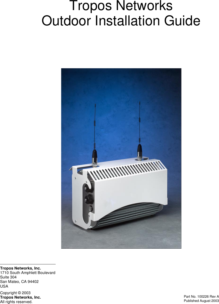
ABB Enterprise Software 51102100 Outdoor Wi-Fi Cell User Manual Outdoor Unit Guide
Tropos Networks, Inc. Outdoor Wi-Fi Cell Outdoor Unit Guide
UserManual.wiki
>
ABB Enterprise Software
>
51102100 User Manual
>
Revised User Manual
Contents
1.
Revised User Manual
2.
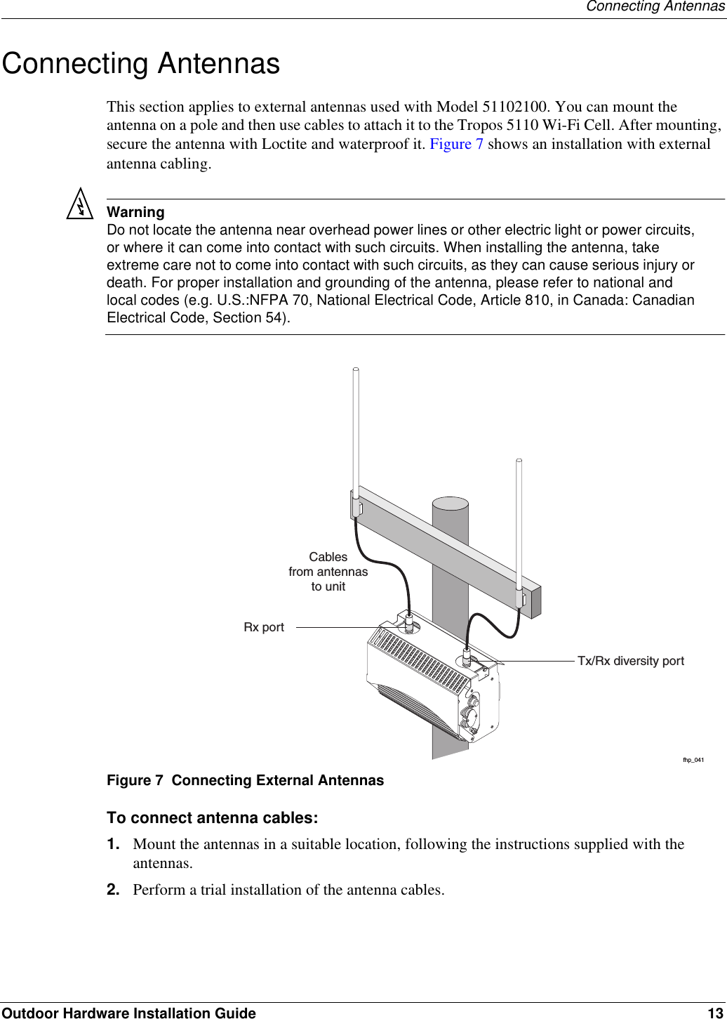
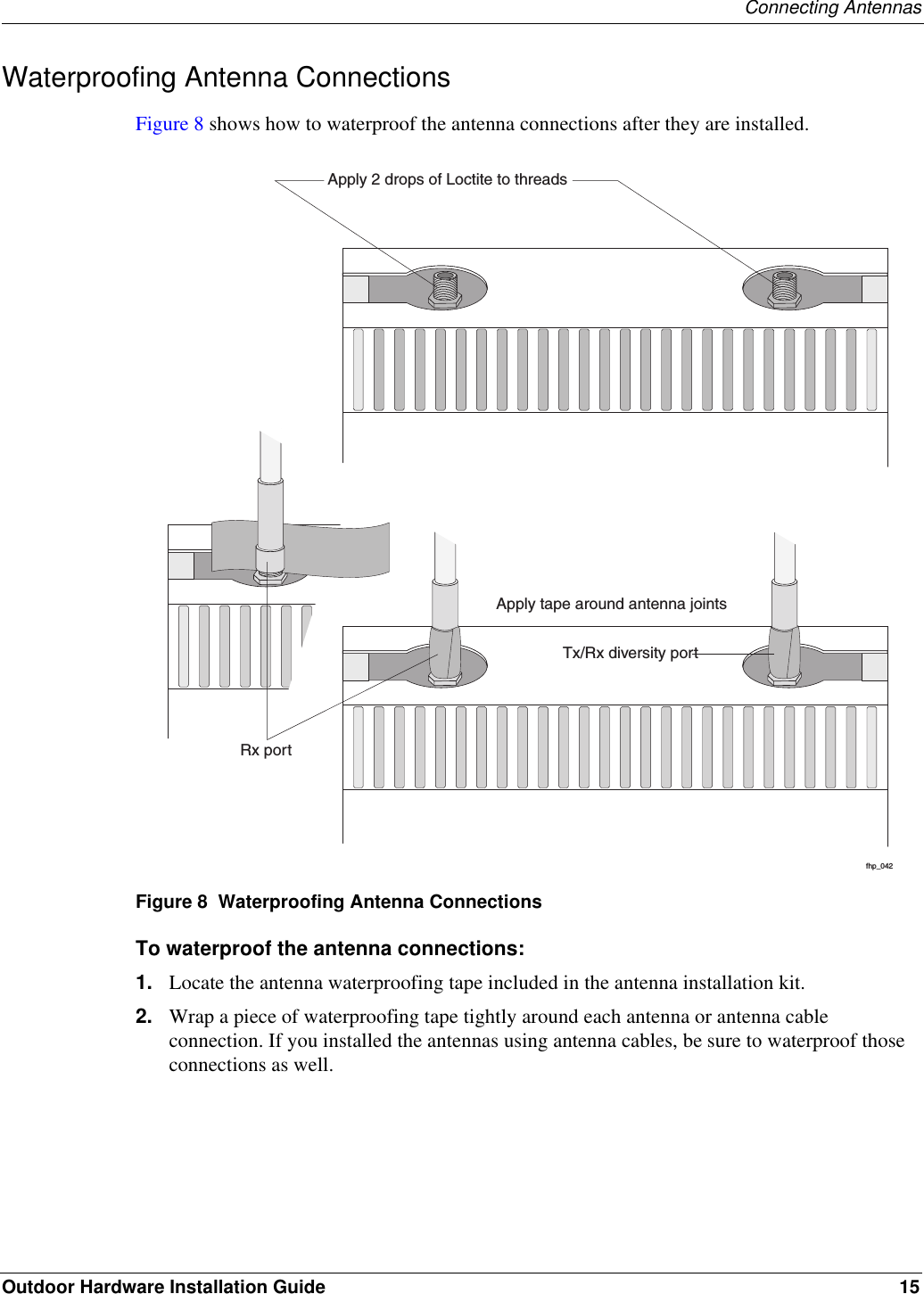
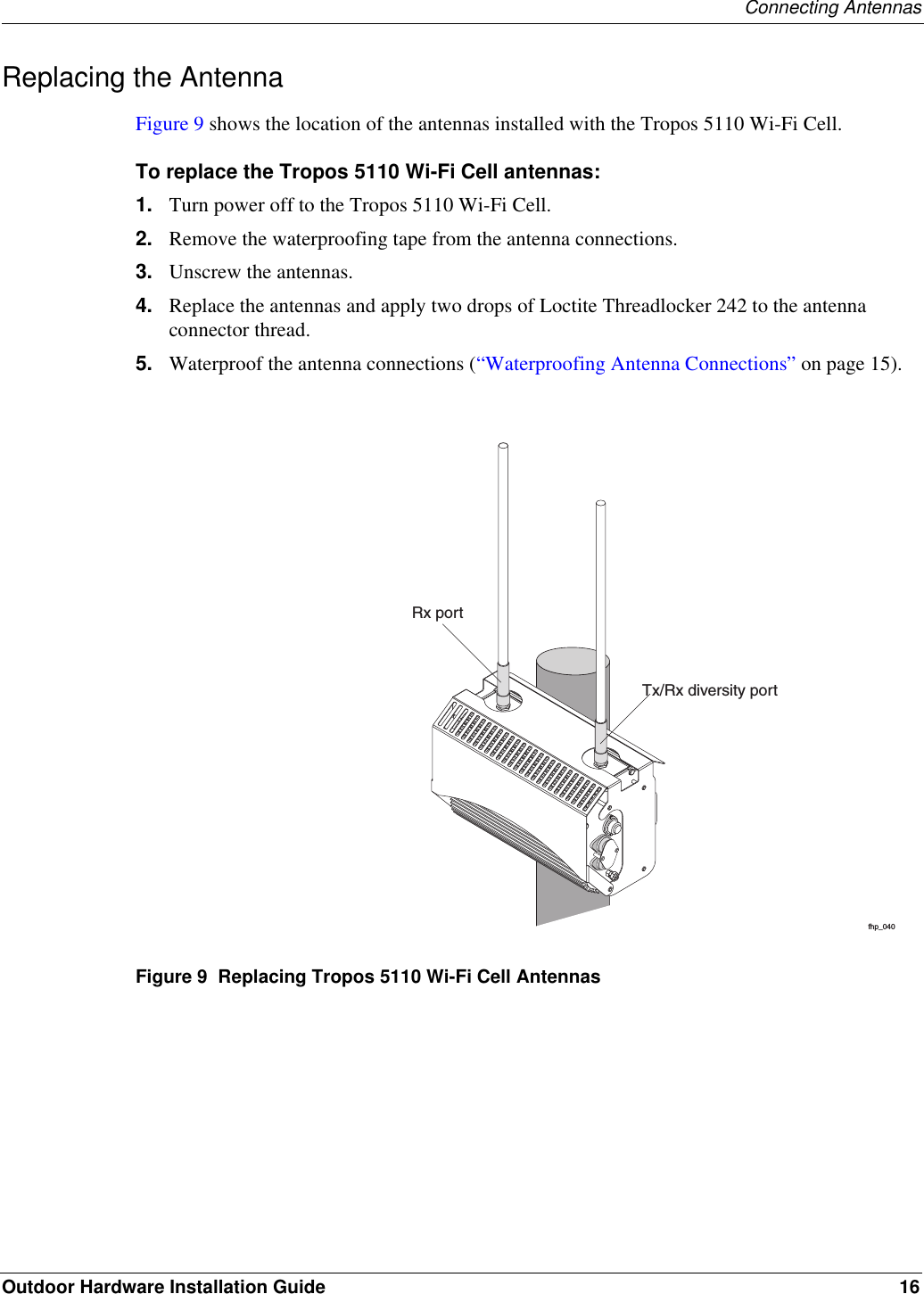
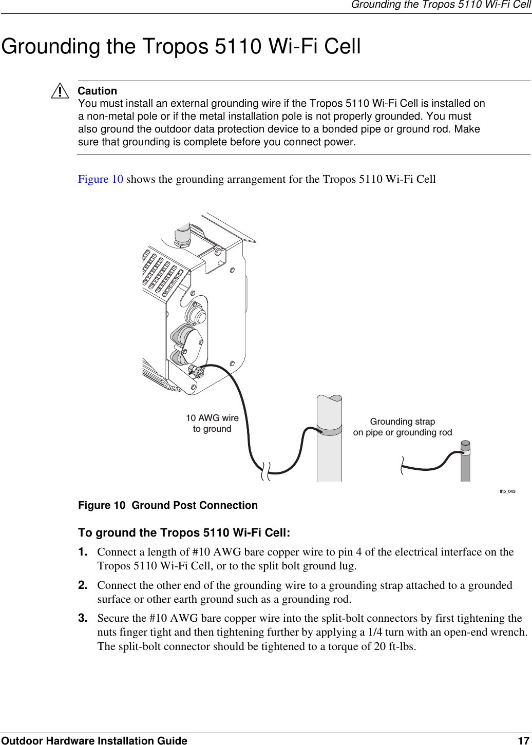
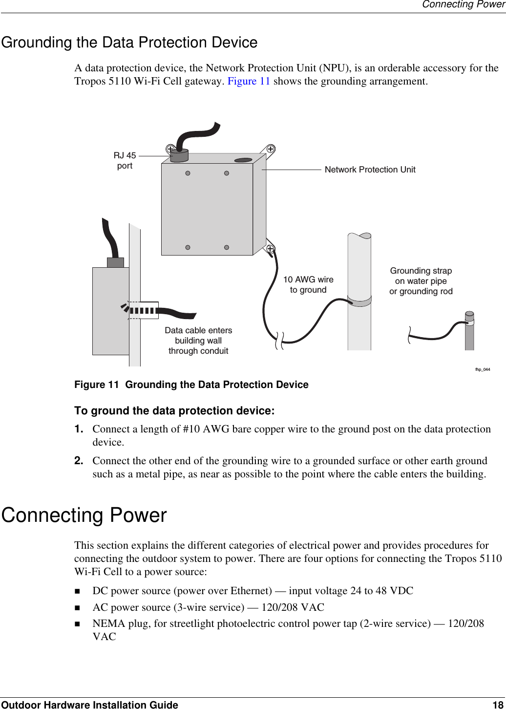
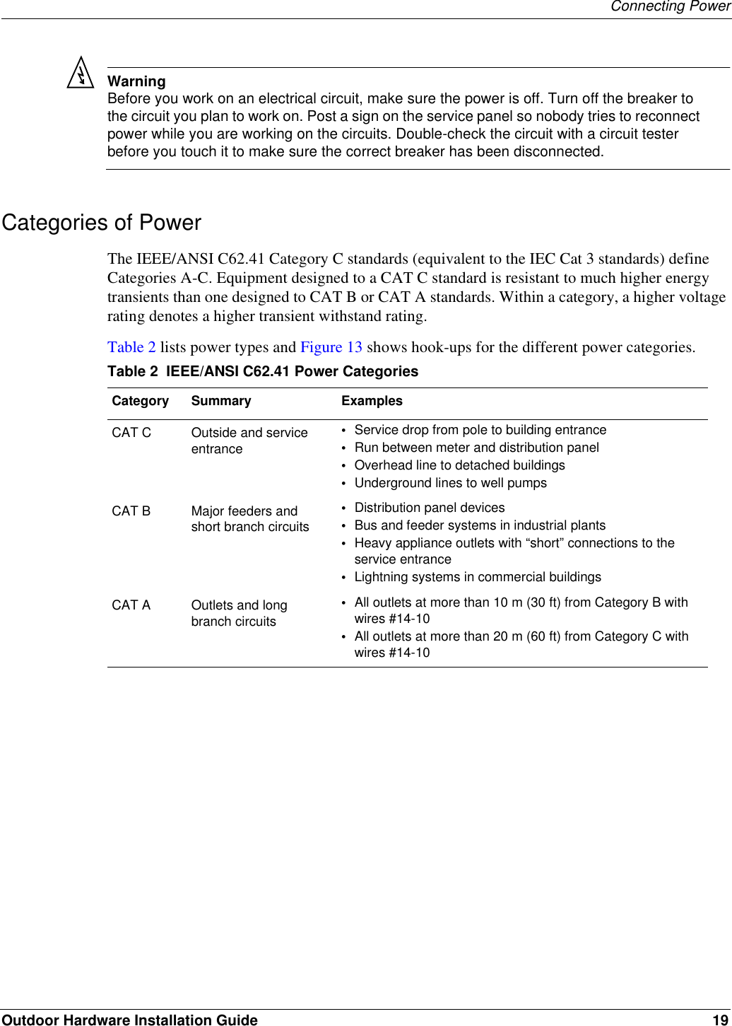
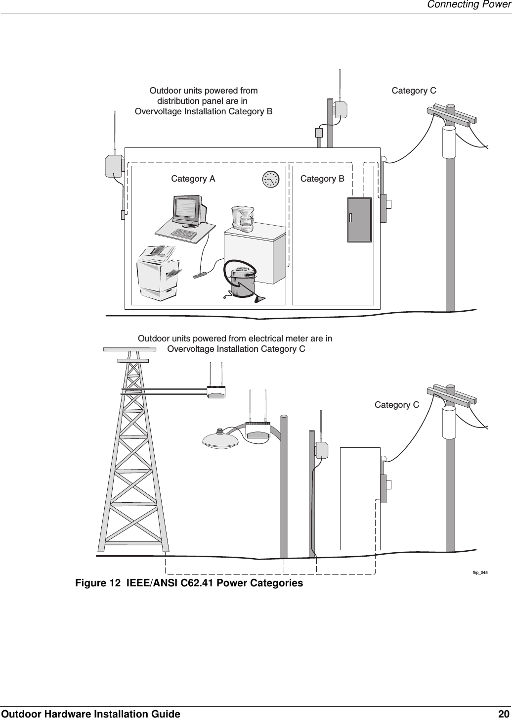
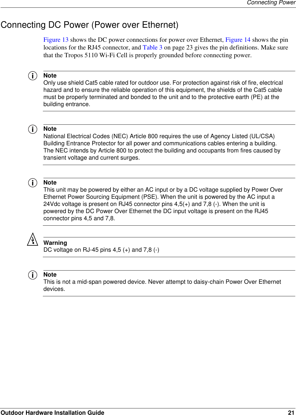
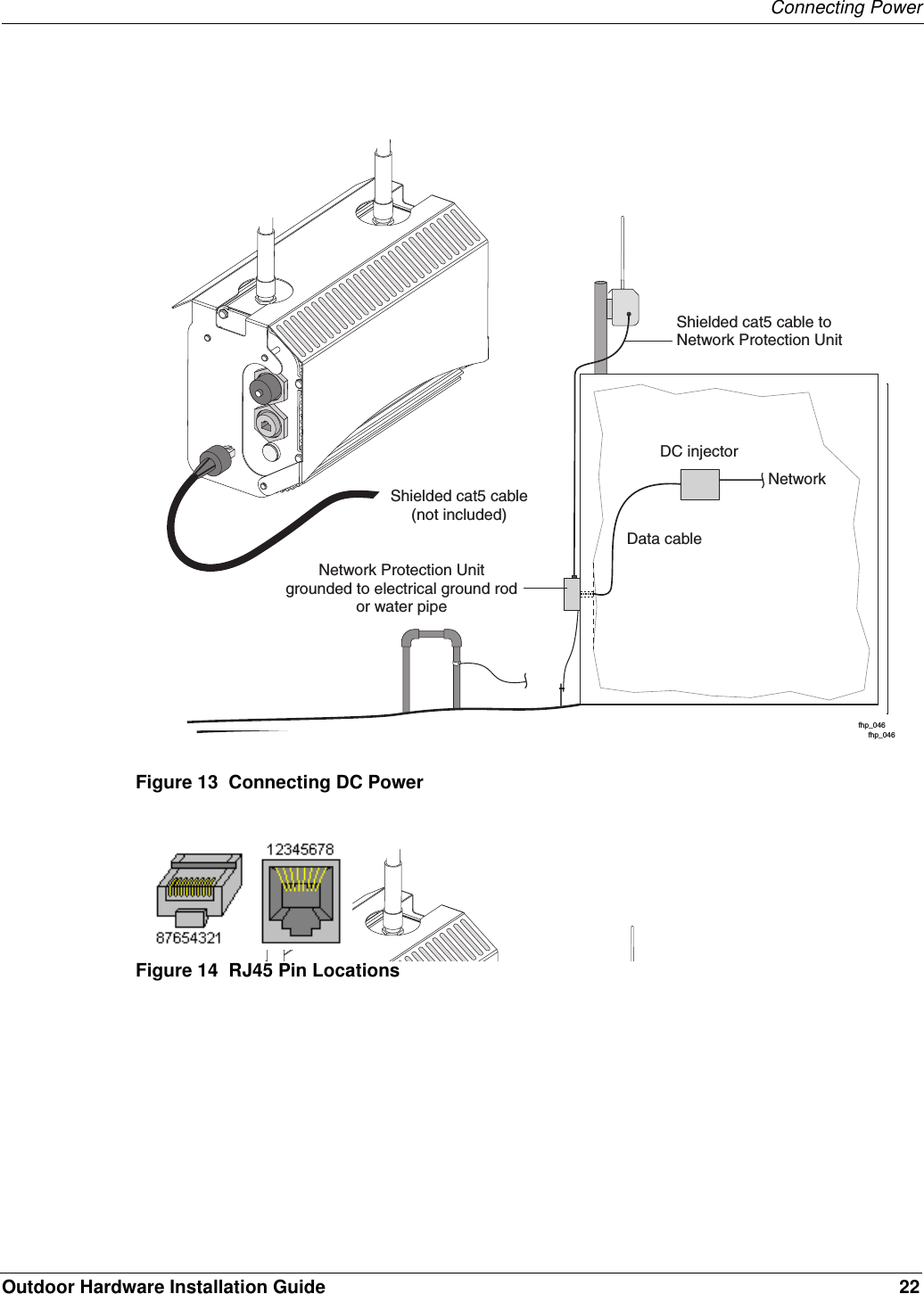
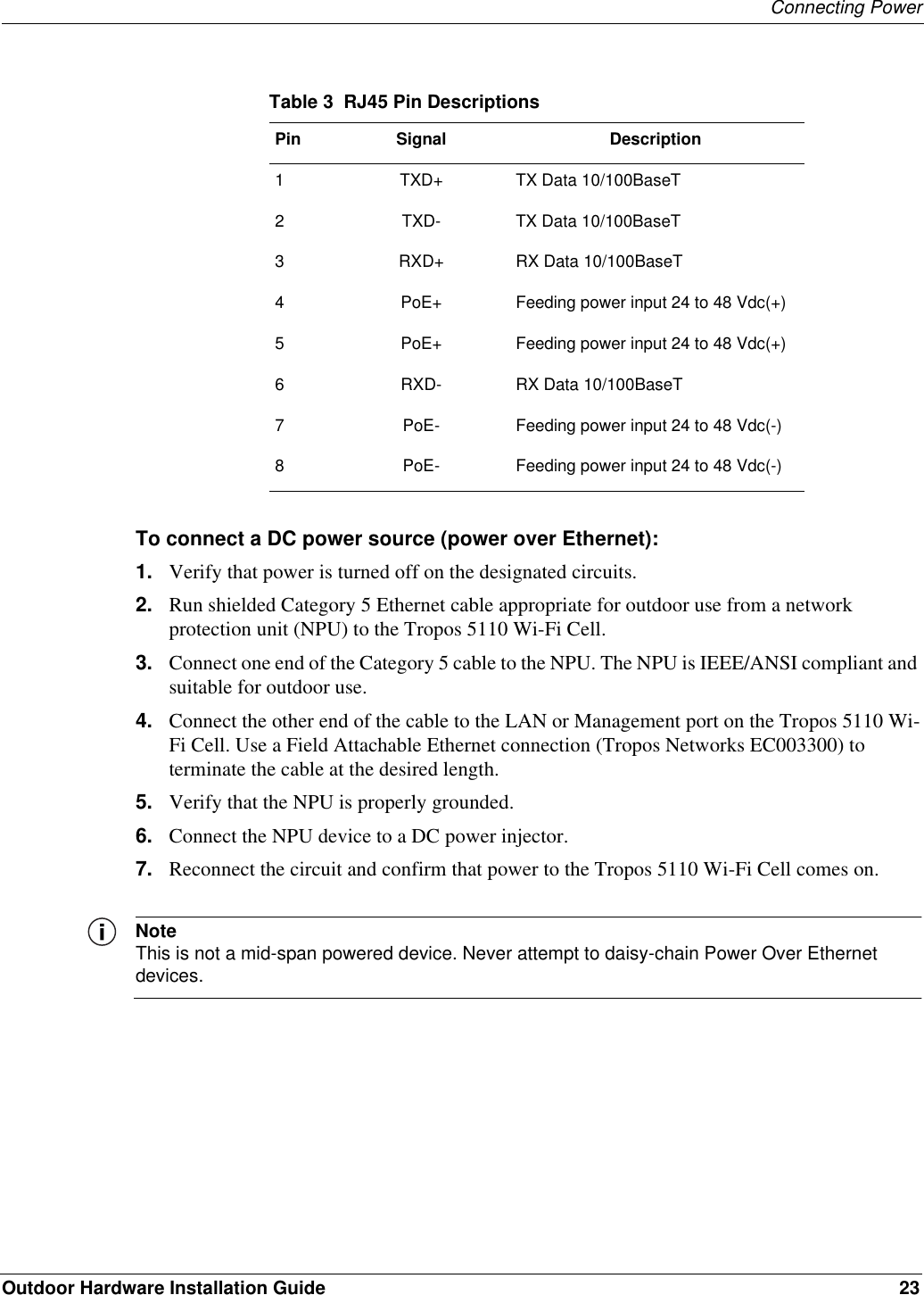
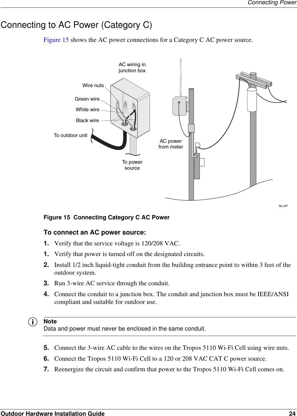
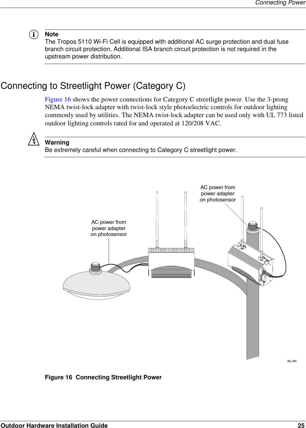
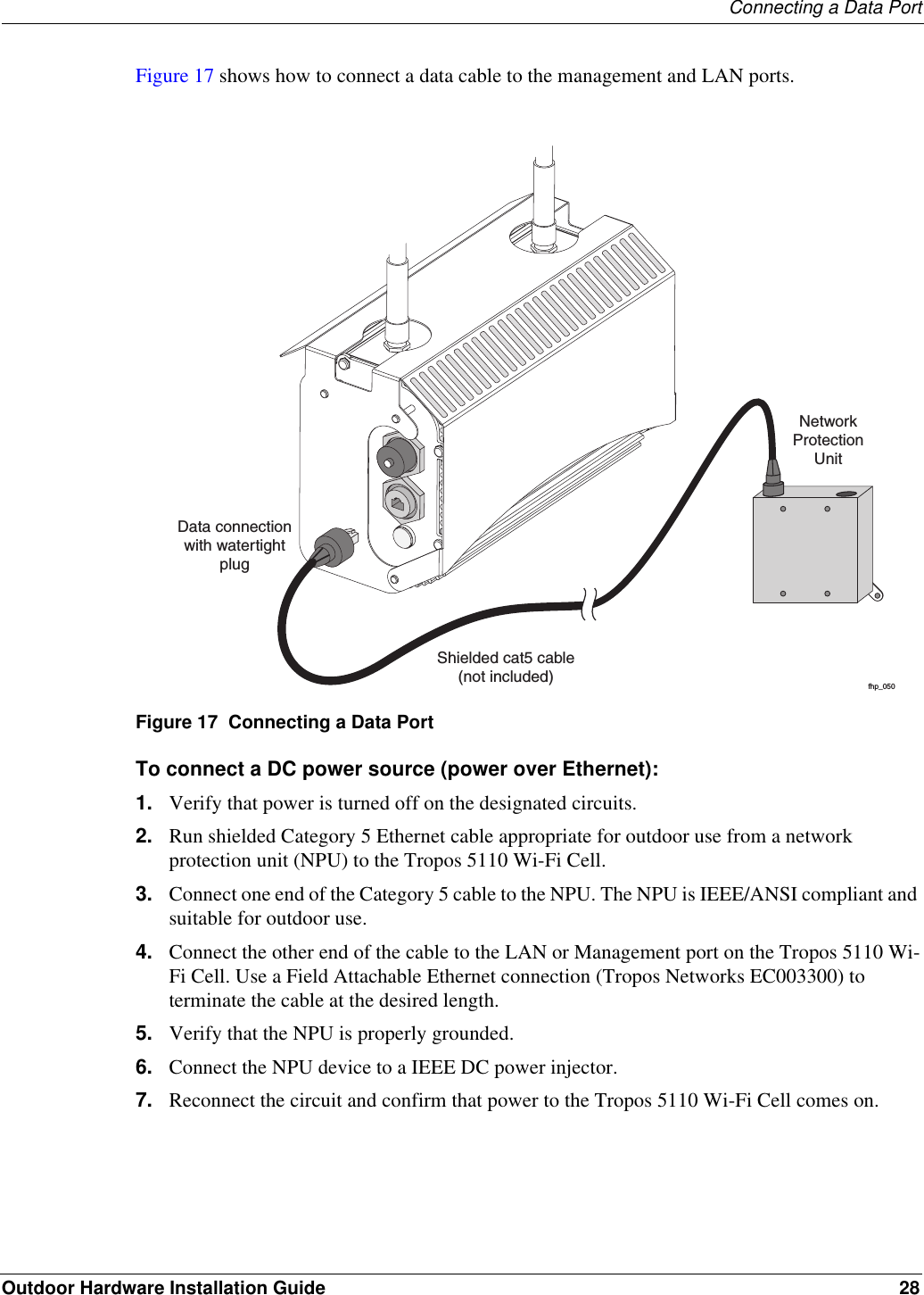
Installation guide addendum
Revised User Manual
Navigation menu
Upload a User Manual
Namespaces
Wiki Guide
HTML
PDF
Info
Views
User Manual
Discussion / Help
Navigation