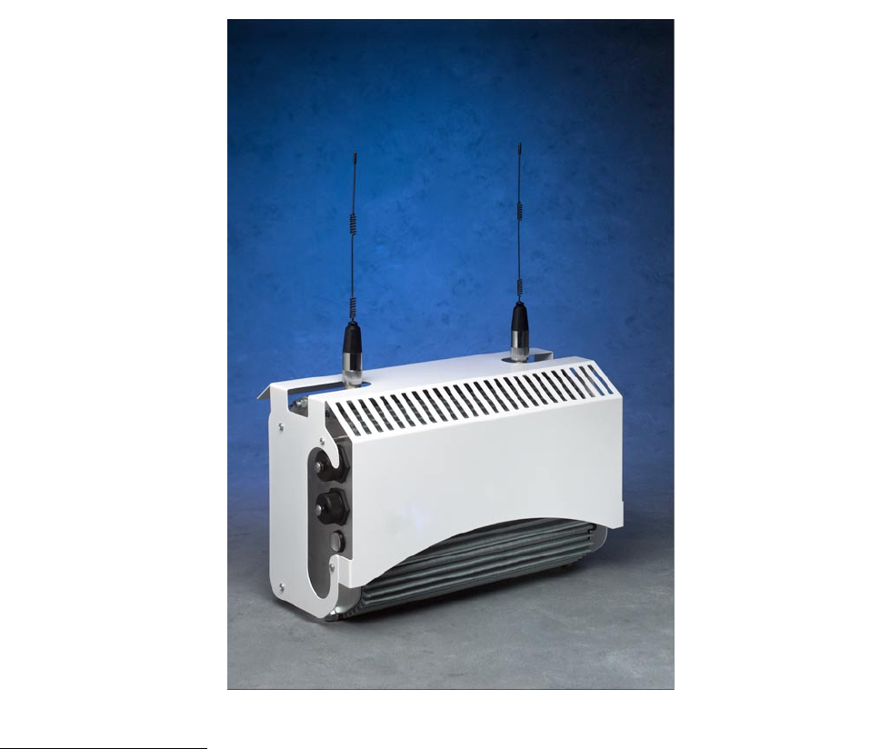
ABB Enterprise Software 51102100 Outdoor Wi-Fi Cell User Manual Outdoor Unit Guide
Tropos Networks, Inc. Outdoor Wi-Fi Cell Outdoor Unit Guide
Contents
- 1. Revised User Manual
- 2. Installation guide addendum
Revised User Manual
Tropos Networks, Inc.
All rights reserved.
Suite 304
San Mateo, CA 94402
USA
1710 South Amphlett Boulevard
Tropos Networks, Inc.
Copyright © 2003 Part No. 100226 Rev A
Published August 2003
Tropos Networks
Outdoor Installation Guide

ii Outdoor Unit Hardware Installation Guide
Copyright Notice
©2003 Tropos Networks, Inc. All rights reserved. Tropos Networks is a registered trademark of
Tropos Networks, Inc. in the United States and certain other jurisdictions. Specifications are
subject to change without notice.
Loctite is a registered trademark of Loctite Corporation, USA.
FCC Notice to Users and Operators
This equipment has been tested and found to comply with the limits for a Class A digital device,
pursuant to Part 15 of the FCC Rules. These limits are designed to provide reasonable protection
against harmful interference when the equipment is operated in a commercial environment. This
equipment generates, uses, and can radiate radio frequency energy and, if not installed and used
in accordance with the instruction manual, may cause harmful interference to radio
communications. Operation of this equipment in a residential area is likely to cause harmful
interference, in which case the user will be required to correct the interference at his own expense.
If this equipment does cause interference to radio or television reception, which can be
determined by turning the equipment off and on, the user is encouraged to correct the interference
by using one of the following measures:
Reorient or relocate the receiving antenna.
Increase separation between the equipment and receiver.
Connect the equipment to an outlet on a circuit different from that to which the receiver is
connected.
Consult the dealer or an experienced radio/TV technician.
This Part 15 radio device operates on a non-interference basis with other devices operating at this
frequency. Any changes or modification to said product not expressly approved by Tropos
Networks could void the user's authority to operate this device.
Warning
You can be killed installing this device!
You can be killed if the 5110 antennas come near electric power lines.
Carefully read and follow all instructions in this manual.
By nature of the installation, you may be exposed to hazardous
environments, and high voltage. Use caution when installing the
outdoor system.

Outdoor Hardware Installation Guide iii
Contents
1 Installing the Tropos 5110 Wi-Fi Cell . . . . . . . . . . . . . . . . . . . . . . . . . . . . . 1
Preparing for Installation . . . . . . . . . . . . . . . . . . . . . . . . . . . . . . . . . . . . . . . . 1
Model Numbers. . . . . . . . . . . . . . . . . . . . . . . . . . . . . . . . . . . . . . . . . . . . . . 1
Installation Hardware and Tools . . . . . . . . . . . . . . . . . . . . . . . . . . . . . . . . . 3
Site Planning . . . . . . . . . . . . . . . . . . . . . . . . . . . . . . . . . . . . . . . . . . . . . . . . 3
Location Guidelines. . . . . . . . . . . . . . . . . . . . . . . . . . . . . . . . . . . . . . . . . . . 3
Antenna Options . . . . . . . . . . . . . . . . . . . . . . . . . . . . . . . . . . . . . . . . . . . . . 4
Site Surveys . . . . . . . . . . . . . . . . . . . . . . . . . . . . . . . . . . . . . . . . . . . . . . . . 4
Power Source . . . . . . . . . . . . . . . . . . . . . . . . . . . . . . . . . . . . . . . . . . . . . . . 4
Safety . . . . . . . . . . . . . . . . . . . . . . . . . . . . . . . . . . . . . . . . . . . . . . . . . . . . . 5
Mounting Instructions . . . . . . . . . . . . . . . . . . . . . . . . . . . . . . . . . . . . . . . . . . . 5
Metal Pole Mounting . . . . . . . . . . . . . . . . . . . . . . . . . . . . . . . . . . . . . . . . . . 6
Wood Pole Mounting. . . . . . . . . . . . . . . . . . . . . . . . . . . . . . . . . . . . . . . . . . 8
Tower Mounting. . . . . . . . . . . . . . . . . . . . . . . . . . . . . . . . . . . . . . . . . . . . . . 9
Streetlight Mounting . . . . . . . . . . . . . . . . . . . . . . . . . . . . . . . . . . . . . . . . . 10
Mounting for Downward Facing Antennas . . . . . . . . . . . . . . . . . . . . . . . . 12
Connecting Antennas. . . . . . . . . . . . . . . . . . . . . . . . . . . . . . . . . . . . . . . . . . 13
Waterproofing Antenna Connections . . . . . . . . . . . . . . . . . . . . . . . . . . . . 15
Replacing the Antenna . . . . . . . . . . . . . . . . . . . . . . . . . . . . . . . . . . . . . . . 16
Grounding the Tropos 5110 Wi-Fi Cell. . . . . . . . . . . . . . . . . . . . . . . . . . . . . 17
Grounding the Data Protection Device . . . . . . . . . . . . . . . . . . . . . . . . . . . 18
Connecting Power . . . . . . . . . . . . . . . . . . . . . . . . . . . . . . . . . . . . . . . . . . . . 18
Categories of Power . . . . . . . . . . . . . . . . . . . . . . . . . . . . . . . . . . . . . . . . . 19
Connecting DC Power (Power over Ethernet). . . . . . . . . . . . . . . . . . . . . . 21
Connecting to AC Power (Category C) . . . . . . . . . . . . . . . . . . . . . . . . . . . 24
Connecting to Streetlight Power (Category C) . . . . . . . . . . . . . . . . . . . . . 25
Connecting a Data Port . . . . . . . . . . . . . . . . . . . . . . . . . . . . . . . . . . . . . . . . 26
Connecting Peripherals . . . . . . . . . . . . . . . . . . . . . . . . . . . . . . . . . . . . . . . . 29
A Safety Information . . . . . . . . . . . . . . . . . . . . . . . . . . . . . . . . . . . . . . . . . . . 30
Safety Information for the Tropos 5110 Wi-Fi Cells . . . . . . . . . . . . . . . . . . . 30
Service Instructions . . . . . . . . . . . . . . . . . . . . . . . . . . . . . . . . . . . . . . . . . . . 31

Outdoor Hardware Installation Guide iv
B Product Specifications . . . . . . . . . . . . . . . . . . . . . . . . . . . . . . . . . . . . . . . 36
C AC Wiring Diagrams . . . . . . . . . . . . . . . . . . . . . . . . . . . . . . . . . . . . . . . . . 40
Index . . . . . . . . . . . . . . . . . . . . . . . . . . . . . . . . . . . . . . . . . . . . . . . . . . . . . . 43

Outdoor Hardware Installation Guide 1
Installing the Tropos 5110 Wi-Fi Cell
This guide explains how to install the Tropos 5110 a Wi-Fi cell safely and is intended for a
trained technical professionals. It covers the following topics:
Preparing for Installation
Mounting Instructions
Connecting Antennas
Grounding the Tropos 5110 Wi-Fi Cell
Connecting Power
Connecting a Data Port
Connecting Peripherals
Preparing for Installation
The Tropos 5110 Wi-Fi Cell must be installed by a trained professional, value added reseller, or
systems integrator who is familiar with RF cell planning issues and regulatory limits defined by
the FCC for RF exposure (sections 1.1307). This section lists the required equipment and model
numbers and explains how to identify and prepare the installation site.
Model Numbers
Table 1 lists the model numbers and ranges for the units discussed in this guide. Figure 1 on
page 2 shows an exploded view of the Tropos 5110 Wi-Fi Cell.
Table 1 Tropos 5110 Wi-Fi Cell Model Numbers
Model Model Number
Tropos 5110 Wi-Fi Cell; -30 deg to 55 deg C; N connectors
(requires external antenna)
51102100
Tropos 5110 Wi-Fi Cell; -30 deg to 55 deg C; 7.4 dBi; Antennas,
bracketry 51103000
Preparing for Installation
Outdoor Hardware Installation Guide 2
Note
The antenna(s) used for this transmitter must be omni directional antennas with a gain of
7.4dBi or less. Antenna(s) must be installed by a trained professional. Operating the unit
with non-qualified antennas is a violation of FCC Rules Part 15.203(c), Code of Federal
Regulations, Title 47.
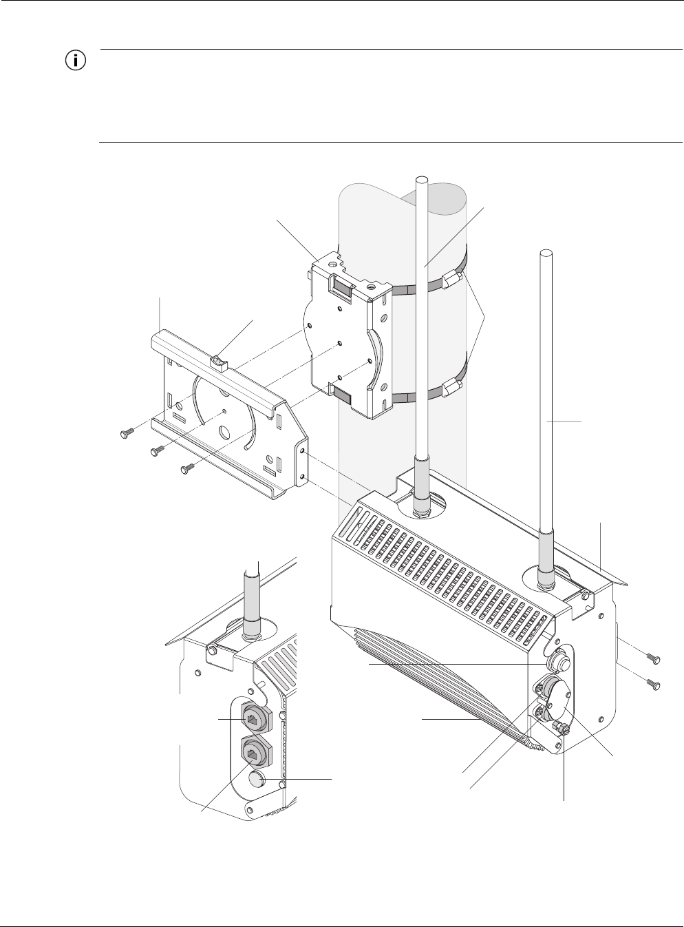
Figure 1 Tropos 5110 Wi-Fi Cell exploded view
fhp_055
10/100 BaseT
LAN port
(PoE input power)
Red/green
status
indicator
Hose
clamps
Rx diversity antenna
Tx/Rx antenna
Sun shield
#10-32 hex head 5/16"
machine screws
x5
Extruded
housing
AC input
power
connector
Split bolt
ground lug
Pole bracket
Bubble
level
Slide bracket
10/100 BaseT
management port
(PoE input power)
Fuse
holders
Fuse
cover guard

Preparing for Installation
Outdoor Hardware Installation Guide 3
Installation Hardware and Tools
Tropos Networks provides the following accessories to install the Tropos 5110 Wi-Fi Cell:
One mounting bracket
Two 4-inch diameter hose clamps
Four 6-inch diameter hose clamps
Five 5/16-inch #10-32 stainless steel hex head machine screws
You must supply the following tools:
5/16 inch nut driver
1/4-inch flat blade screwdriver
Tower mounting only: supply stainless or galvanized steel channel stock and 1/2-inch or
5/8-inch nuts, bolts, and washers to connect to the tower arm.
Wood pole mounting only: two 5/8-inch diameter, 3-inch long lag bolts
Site Planning
To ensure safe and durable wiring, installation of the Tropos 5110 Wi-Fi Cell must follow
appropriate electrical and building codes. Follow the National Electrical Code (NEC)
requirements, unless local codes in your area take precedence over the NEC code.
The following distance limits apply to installations that have 10/100 Base-T Category 5 network
cables attached to the Tropos 5110 Wi-Fi Cell:
100 meters between devices for 100BaseT operation
366 meters for 10BaseT operation.
The Ethernet duplex and speed setting is configurable.
Location Guidelines
The Tropos 5110 Wi-Fi Cell is a radio device and therefore susceptible to interference that can
reduce throughput and range. Follow these guidelines to ensure the best performance:
Install the unit in an area where trees, buildings, and large steel structures do not obstruct
radio signals to and from the antenna. Direct line-of-sight operation is best.
Install the unit away from microwave ovens or other devices operating in the 2.4 GHz
frequency range.
Install the units away from other possible sources of 2.4 GHz WLAN interference, such as
cordless phones, home spy cameras, frequency hopping (FHSS) and DSSS LAN
transceivers (non-802.11b), electronic news gathering video links, radars, amateur radios,
land mobile radio services, local government sites (such as law enforcement), fixed
microwave services, local TV transmission and private fixed point transmitters.

Preparing for Installation
Outdoor Hardware Installation Guide 4
Antenna Options
You can purchase the Tropos 5110 Wi-Fi Cell with an integrated omni-directional antenna
(Model 51103000) or use your own external antenna (Model 51102100). Omni-directional
antennas are best for systems requiring a signal distribution in more than one direction. To
comply with FCC RF exposure limits, locate antennas at a minimum distance of 7.9 inches
(20cm) from people.
Note
The antenna(s) used for this transmitter must be omni directional antennas with a gain of
7.4dBi or less. Antenna(s) must be installed by a trained professional. Operating the unit
with non-qualified antennas is a violation of FCC Rules Part 15.203(c), Code of Federal
Regulations, Title 47.
Site Surveys
Due to; variations in component configuration, placement, and physical environment, each
installation is unique. Before installing the Tropos 5110 Wi-Fi Cell, perform a site survey to
determine the optimum placement of units for maximum range, coverage, and network
performance. Consider the following factors when performing a site survey:
Data rates—Sensitivity and range are inversely proportional to data bit rates. The maximum
radio range is achieved at the lowest workable data rate. A decrease in receiver threshold
sensitivity occurs as radio data increases.
Antenna type and placement—Proper antenna configuration is a critical factor in
maximizing radio range. As a general rule, range increases in proportion to antenna height
and gain.
Physical environment—Clear or open areas provide better radio range than closed or filled
areas. The less cluttered the operating environment, the greater the range.
Obstructions—A physical obstruction, such as a building or tree, can block or hinder
communication. Avoid locating antennas in a location where there is an obstruction between
sending and receiving antennas.
Building materials—Radio penetration is influenced by the building material used in
construction. For example, drywall construction permits greater range than concrete blocks.
Metal or steel construction is a barrier to radio signals.
Diversity—The Tropos 5110 Wi-Fi Cell supports RX diversity, which requires two
antennas.
Power Source
The Tropos 5110 Wi-Fi Cell supports 4 options for connecting to a power source:
DC power source (power over Ethernet) — input voltage 24 to 48 VDC
AC power source (3-wire service) — 120/208 VAC

Mounting Instructions
Outdoor Hardware Installation Guide 5
NEMA plug, for streetlight photoelectric control power tap (2-wire service) — 120/208
VAC
Warning
Connect the AC powered outdoor system only to 120/208V AC power sources. Do not
connect it to a power source of higher voltage.
Safety
Installing the Tropos 5110 Wi-Fi Cell can pose a serious hazard. Be sure to take precautions to
avoid the following:
Exposure to high voltage lines during installation
Falls when working at heights or with ladders
Injuries from dropping tools
Contact with AC wiring
Mounting Instructions
This section explains how to mount the Tropos 5110 Wi-Fi Cell on a pole, tower, or streetlight.
Note
The sun shield for the Tropos 5110 Wi-Fi Cell is designed to accommodate antennas facing
upward. If conditions at the installation site require that the antennas face downward, you
must remove the sun shield and reattach it upside down. See “Mounting for Downward
Facing Antennas” on page 12.
Mounting Instructions
Outdoor Hardware Installation Guide 6
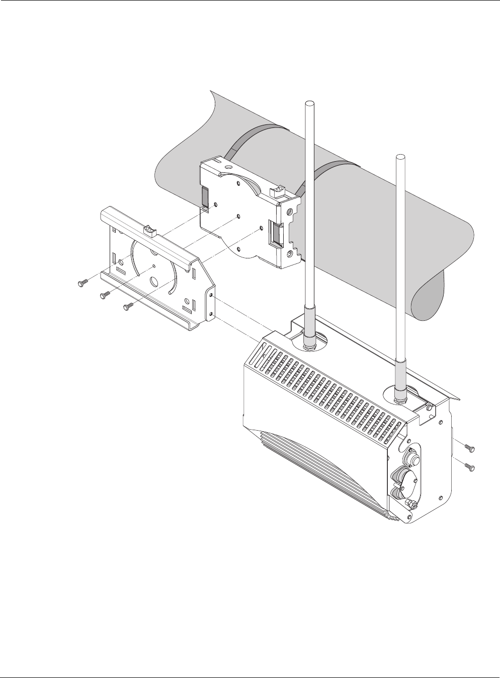
Metal Pole Mounting
Figure 2 shows a typical installation with the Tropos 5110 Wi-Fi Cell mounted on an outdoor
metal pole.
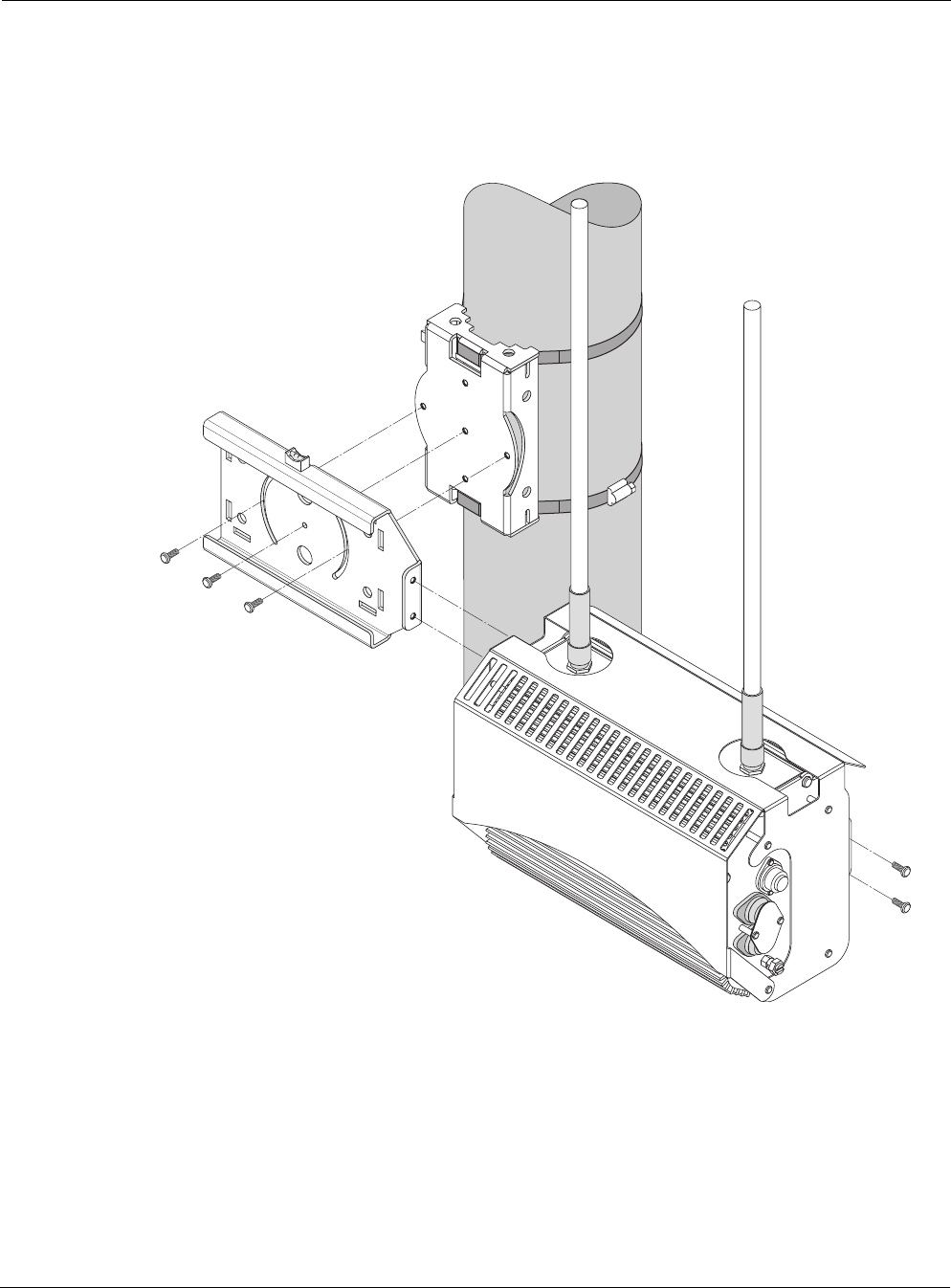
Figure 2 Metal Pole Mounting
To mount the Tropos 5110 Wi-Fi Cell on a metal pole:
1. Select a mounting location. You can attach the Tropos 5110 Wi-Fi Cell to any pipe or pole
with diameter 1.75” to 10”.
2. If the pole is vertical, use a 5/16-inch nut driver to remove the 3 bolts that attach the pole
bracket to the sliding bracket. Rotate the pole bracket 90 degrees and reattach it to the
fhp 037
Sliding bracket
Pole bracket (rotated)
Tropos 5110 Wi-Fi Cell
with sun shield

Mounting Instructions
Outdoor Hardware Installation Guide 7
sliding bracket. Tighten the center bolt, but keep the bolts in the curved grooves slightly
loose to permit rotation.
3. Slip the flat portion of the hose clamps under the inside lips of the pole bracket.
4. Use the hose clamps to attach the pole bracket to the pole. Depending upon the diameter of
the pole, you may need to use a single small clamp, single large clamp, or pair of large
clamps joined together.
5. Level the pole bracket by adjusting the hose clamp and rotating the bracket along the curved
grooves. Use the internal bubble levels for reference.
6. Tighten all the mounting bolts.
7. Slide the Tropos 5110 Wi-Fi Cell into place and secure it at the end with two #10-32 hex
head machine screws.
To continue installing the outdoor system, see “Connecting Antennas” on page 13.
Mounting Instructions
Outdoor Hardware Installation Guide 8
Wood Pole Mounting
Figure 3 shows a typical installation with the Tropos 5110 Wi-Fi Cell mounted on an outdoor
wood pole.
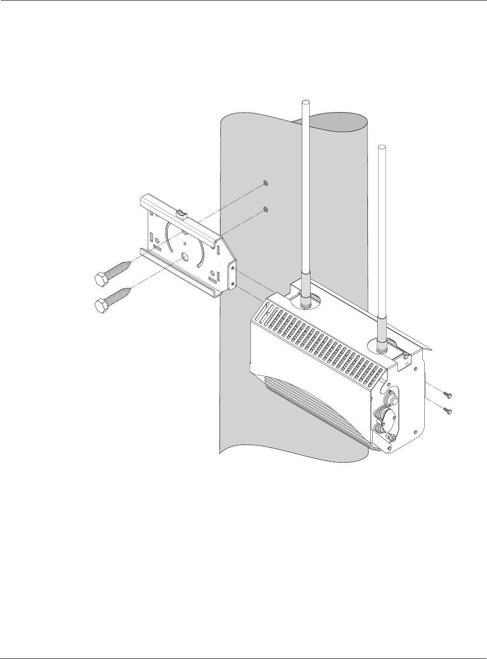
Figure 3 Wood Pole Mounting
To mount the Tropos 5110 Wi-Fi Cell on a wood pole:
1. Select a mounting location. You can attach the Tropos 5110 Wi-Fi Cell to any outdoor wood
pole of diameter at least 1.75 inches.
2. Remove the pole bracket from the sliding bracket.
3. Level the sliding bracket against the pole.
4. Use two 5/8-inch lag bolts to attach the sliding bracket to the pole.
fhp_037w
Mounting Instructions
Outdoor Hardware Installation Guide 9
5. Slide the Tropos 5110 Wi-Fi Cell into place and secure it at the end with two #10-32 hex
head machine screws.
To continue installing the outdoor system, see “Connecting Antennas” on page 13.
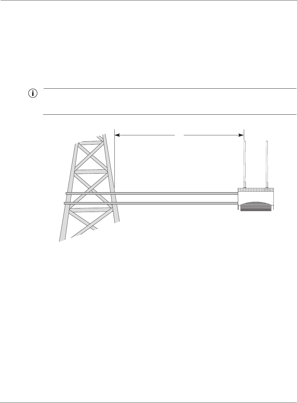
Tower Mounting
You can mount the outdoor system to an outdoor tower.
Note
At the antenna level, the Tropos 5110 Wi-Fi Cell must be free from metal obstruction within
a 4-foot radius (Figure 4 on page 9).
Figure 4 Tower Mounting
To mount the Tropos 5110 Wi-Fi Cell on a tower:
1. Remove the pole bracket from the sliding bracket.
2. Make a tower bracket by attaching the sliding bracket directly to any stainless steel or
galvanized steel channel stock.
3. Attach the bracket assembly to the tower arm so that the slides are horizontal.
4. Level the bracket assembly by rotating the sliding bracket along the curved grooves.
5. Tighten the mounting bolts.
6. Slide the Tropos 5110 Wi-Fi Cell into place and secure it at the end with two #10-32 hex
head machine screws.
To continue installing the outdoor system, see “Connecting Antennas” on page 13.
4'
Brackets not included
Channel stock
Mounting Instructions
Outdoor Hardware Installation Guide 10
Streetlight Mounting
You can mount the Tropos 5110 Wi-Fi Cell on the horizontal or angled arm of a streetlight.
Figure 2shows a typical streetlight mounting installation.
Figure 5 Streetlight Mounting
To mount the Tropos 5110 Wi-Fi Cell on a streetlight:
1. Select a mounting location. You can attach the Tropos 5110 Wi-Fi Cell to any streetlight
arm with diameter 1.75” to 10”.
2. If the angle of the streetlight arm has a vertical orientation, use a 5/16-inch nut driver to
remove the 3 bolts that attach the pole bracket to the sliding bracket. Rotate the pole bracket
fhp_039

Mounting Instructions
Outdoor Hardware Installation Guide 11
90 degrees and reattach it to the sliding bracket. Tighten the center bolt, but keep the bolts in
the curved grooves slightly loose to permit rotation.
3. Slip the flat portion of the hose clamp under the inside lip of the pole bracket.
4. Use the hose clamps to attach the pole bracket to the streetlight. Depending upon the
diameter of the pole, you may need to use a single small clamp, single large clamp, or pair of
large clamps joined together.
5. Level the pole bracket by adjusting the hose clamp and rotating the bracket along the curved
grooves. Use the internal bubble levels for reference.
6. Tighten all the mounting bolts.
7. Slide the Tropos 5110 Wi-Fi Cell into place and secure it at the end with two #10-32 hex
head machine screws.
To continue installing the outdoor system, see “Connecting Antennas” on page 13.
Mounting Instructions
Outdoor Hardware Installation Guide 12
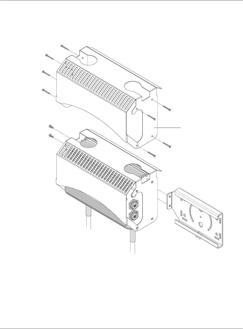
Mounting for Downward Facing Antennas
In areas with significant ice and snow, it may be desirable to mount the Tropos 5110 Wi-Fi Cell
with the antenna facing downward. To do so, you must remove the Tropos 5110 Wi-Fi Cell from
its sun shield and reattach it facing downward (Figure 6).
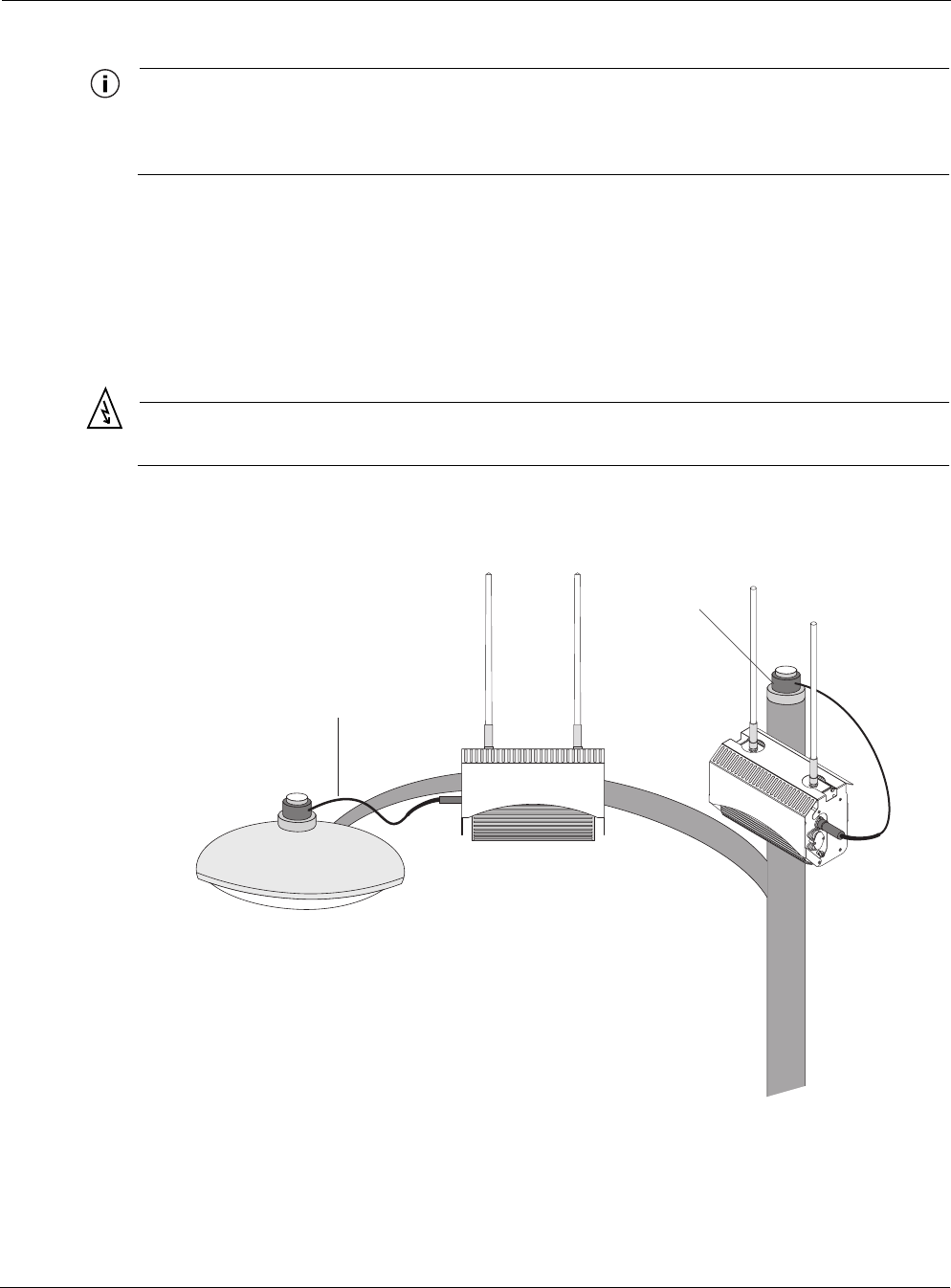
Figure 6 Reattaching sun shield for downward facing antennas
To prepare for downward facing antennas:
1. Remove the 8 screws that connect the Tropos 5110 Wi-Fi Cell to its sun shield.
2. Invert the sun shield so that the Tropos 5110 Wi-Fi Cell antennas face towards the bottom of
the shield.
3. Reattach and tighten the 8 screws to secure the Tropos 5110 Wi-Fi Cell to the sun shield.
Remove and flip sun shield
to reinstall to outdoor unit
with antennas oriented
downward
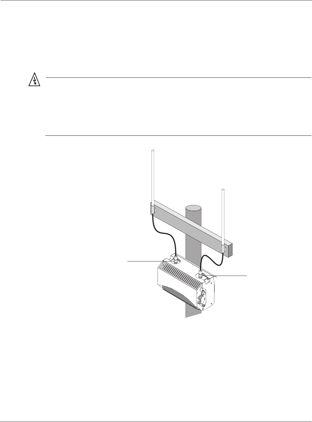
Connecting Antennas
Outdoor Hardware Installation Guide 13
Connecting Antennas
This section applies to external antennas used with Model 51102100. You can mount the
antenna on a pole and then use cables to attach it to the Tropos 5110 Wi-Fi Cell. After mounting,
secure the antenna with Loctite and waterproof it. Figure 7 shows an installation with external
antenna cabling.
Warning
Do not locate the antenna near overhead power lines or other electric light or power circuits,
or where it can come into contact with such circuits. When installing the antenna, take
extreme care not to come into contact with such circuits, as they can cause serious injury or
death. For proper installation and grounding of the antenna, please refer to national and
local codes (e.g. U.S.:NFPA 70, National Electrical Code, Article 810, in Canada: Canadian
Electrical Code, Section 54).
Figure 7 Connecting External Antennas
To connect antenna cables:
1. Mount the antennas in a suitable location, following the instructions supplied with the
antennas.
2. Perform a trial installation of the antenna cables.
fh
p
_041
Tx/Rx diversity port
Cables
from antennas
to unit
Rx port

Connecting Antennas
Outdoor Hardware Installation Guide 14
3. When you are satisfied with the trial placement of the antenna cables, remove the antenna
connections from the Tropos 5110 Wi-Fi Cell and apply two drops of Loctite Threadlocker
242 to the antenna connector thread (Figure 8 on page 15).
4. Install the antenna cables.
Note
To ensure good electrical contact with the antenna, do not get Loctite on the center
conductor pin of the antenna cable or outdoor system connector.
Note
The antenna(s) used for this transmitter must be omni directional antennas with a gain of
7.4dBi or less. Antenna(s) must be installed by a trained professional. Operating the unit
with non-qualified antennas is a violation of FCC Rules Part 15.203(c), Code of Federal
Regulations, Title 47.
Connecting Antennas
Outdoor Hardware Installation Guide 15
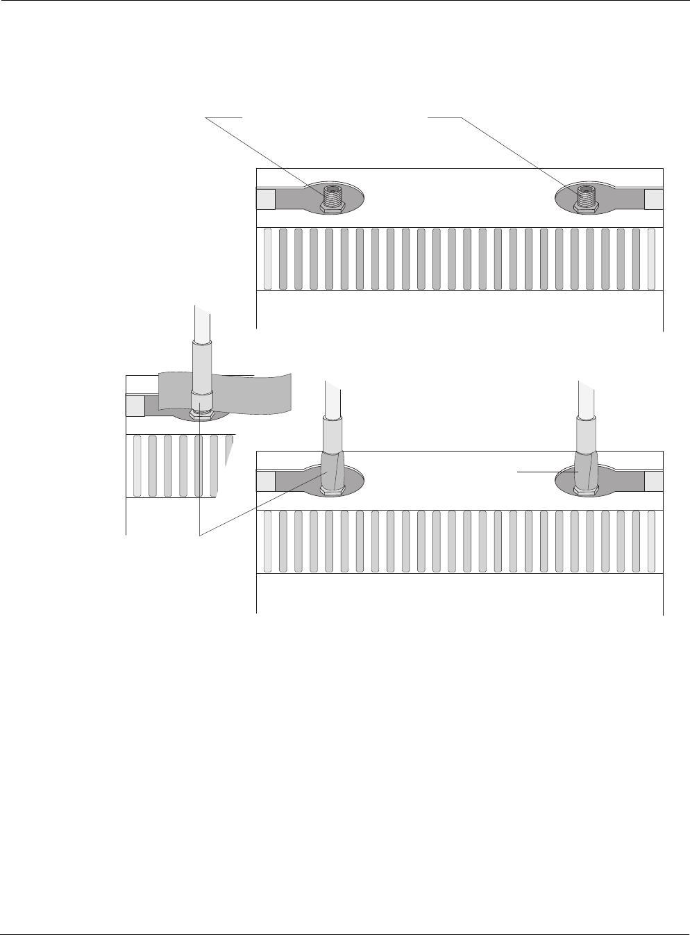
Waterproofing Antenna Connections
Figure 8 shows how to waterproof the antenna connections after they are installed.
Figure 8 Waterproofing Antenna Connections
To waterproof the antenna connections:
1. Locate the antenna waterproofing tape included in the antenna installation kit.
2. Wrap a piece of waterproofing tape tightly around each antenna or antenna cable
connection. If you installed the antennas using antenna cables, be sure to waterproof those
connections as well.
fh
p
_042
Apply tape around antenna joints
Apply 2 drops of Loctite to threads
Rx port
Tx/Rx diversity port
Connecting Antennas
Outdoor Hardware Installation Guide 16
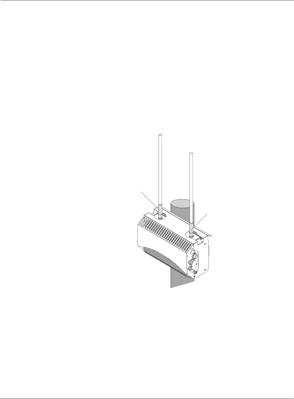
Replacing the Antenna
Figure 9 shows the location of the antennas installed with the Tropos 5110 Wi-Fi Cell.
To replace the Tropos 5110 Wi-Fi Cell antennas:
1. Turn power off to the Tropos 5110 Wi-Fi Cell.
2. Remove the waterproofing tape from the antenna connections.
3. Unscrew the antennas.
4. Replace the antennas and apply two drops of Loctite Threadlocker 242 to the antenna
connector thread.
5. Waterproof the antenna connections (“Waterproofing Antenna Connections” on page 15).
Figure 9 Replacing Tropos 5110 Wi-Fi Cell Antennas
fhp_040
Tx/Rx diversity port
Rx port
Grounding the Tropos 5110 Wi-Fi Cell
Outdoor Hardware Installation Guide 17
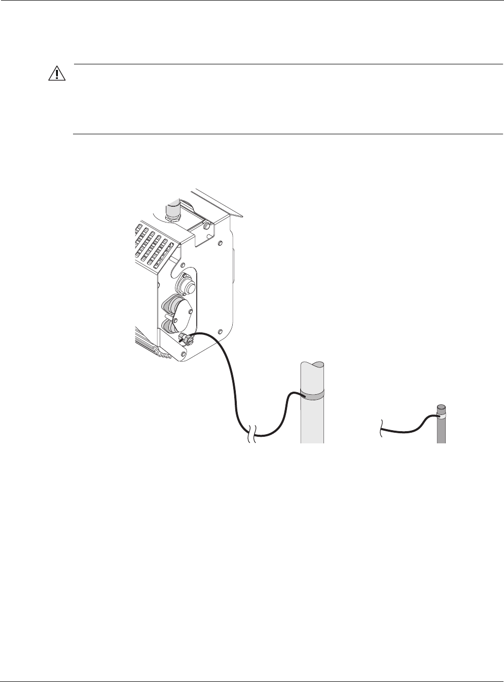
Grounding the Tropos 5110 Wi-Fi Cell
Caution
You must install an external grounding wire if the Tropos 5110 Wi-Fi Cell is installed on
a non-metal pole or if the metal installation pole is not properly grounded. You must
also ground the outdoor data protection device to a bonded pipe or ground rod. Make
sure that grounding is complete before you connect power.
Figure 10 shows the grounding arrangement for the Tropos 5110 Wi-Fi Cell
Figure 10 Ground Post Connection
To ground the Tropos 5110 Wi-Fi Cell:
1. Connect a length of #10 AWG bare copper wire to pin 4 of the electrical interface on the
Tropos 5110 Wi-Fi Cell, or to the split bolt ground lug.
2. Connect the other end of the grounding wire to a grounding strap attached to a grounded
surface or other earth ground such as a grounding rod.
3. Secure the #10 AWG bare copper wire into the split-bolt connectors by first tightening the
nuts finger tight and then tightening further by applying a 1/4 turn with an open-end wrench.
The split-bolt connector should be tightened to a torque of 20 ft-lbs.
fhp_043
10 AWG wire
to ground Grounding strap
on pipe or grounding rod
Connecting Power
Outdoor Hardware Installation Guide 18
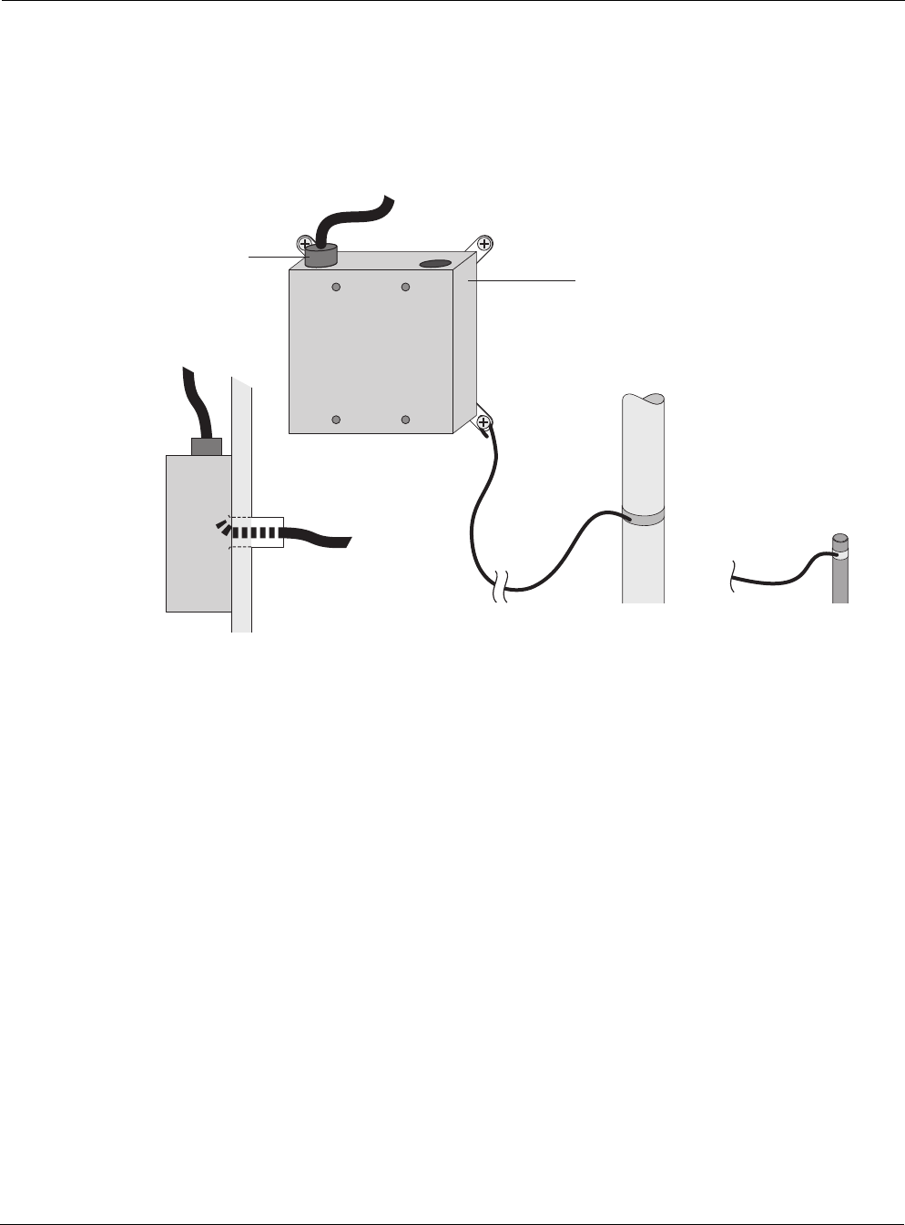
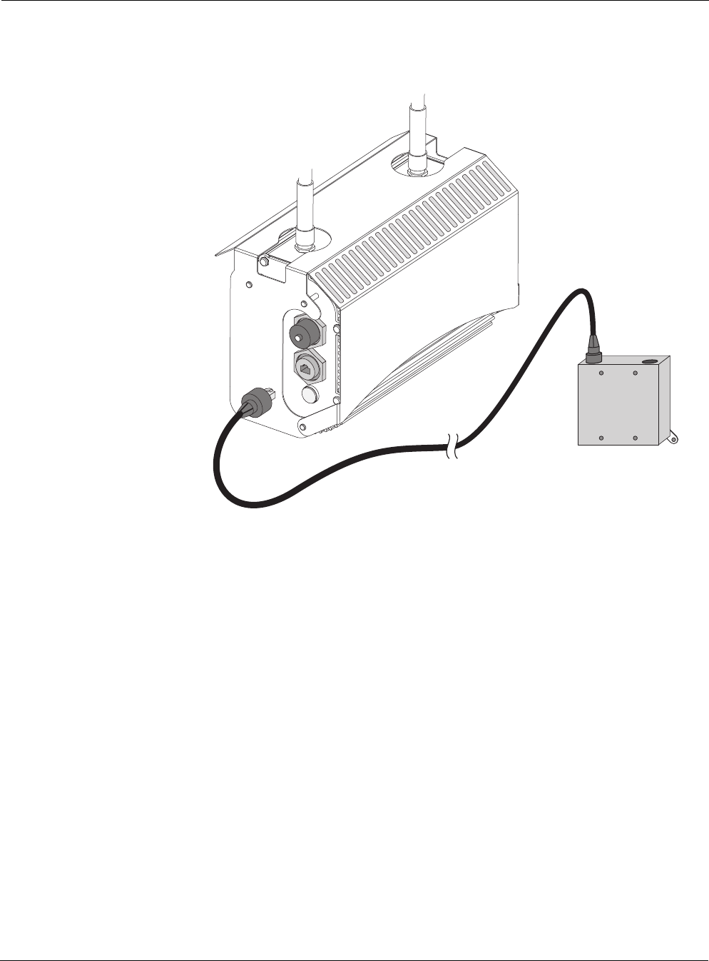
Grounding the Data Protection Device
A data protection device, the Network Protection Unit (NPU), is an orderable accessory for the
Tropos 5110 Wi-Fi Cell gateway. Figure 11 shows the grounding arrangement.
Figure 11 Grounding the Data Protection Device
To ground the data protection device:
1. Connect a length of #10 AWG bare copper wire to the ground post on the data protection
device.
2. Connect the other end of the grounding wire to a grounded surface or other earth ground
such as a metal pipe, as near as possible to the point where the cable enters the building.
Connecting Power
This section explains the different categories of electrical power and provides procedures for
connecting the outdoor system to power. There are four options for connecting the Tropos 5110
Wi-Fi Cell to a power source:
DC power source (power over Ethernet) — input voltage 24 to 48 VDC
AC power source (3-wire service) — 120/208 VAC
NEMA plug, for streetlight photoelectric control power tap (2-wire service) — 120/208
VAC
fhp_044
10 AWG wire
to ground
Grounding strap
on water pipe
or grounding rod
Network Protection Unit
RJ 45
port
Data cable enters
building wall
through conduit
fhp_044
10 AWG wire
to ground
Grounding strap
on water pipe
or grounding rod
Network Protection Unit
RJ 45
port
Data cable enters
building wall
through conduit

Connecting Power
Outdoor Hardware Installation Guide 19
Warning
Before you work on an electrical circuit, make sure the power is off. Turn off the breaker to
the circuit you plan to work on. Post a sign on the service panel so nobody tries to reconnect
power while you are working on the circuits. Double-check the circuit with a circuit tester
before you touch it to make sure the correct breaker has been disconnected.
Categories of Power
The IEEE/ANSI C62.41 Category C standards (equivalent to the IEC Cat 3 standards) define
Categories A-C. Equipment designed to a CAT C standard is resistant to much higher energy
transients than one designed to CAT B or CAT A standards. Within a category, a higher voltage
rating denotes a higher transient withstand rating.
Table 2 lists power types and Figure 13 shows hook-ups for the different power categories.
Table 2 IEEE/ANSI C62.41 Power Categories
Category Summary Examples
CAT C Outside and service
entrance
•Service drop from pole to building entrance
•Run between meter and distribution panel
•Overhead line to detached buildings
•Underground lines to well pumps
CAT B Major feeders and
short branch circuits
•Distribution panel devices
•Bus and feeder systems in industrial plants
•Heavy appliance outlets with “short” connections to the
service entrance
•Lightning systems in commercial buildings
CAT A Outlets and long
branch circuits
•All outlets at more than 10 m (30 ft) from Category B with
wires #14-10
•All outlets at more than 20 m (60 ft) from Category C with
wires #14-10
Connecting Power
Outdoor Hardware Installation Guide 20
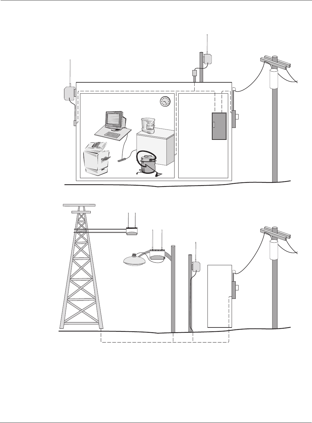
Figure 12 IEEE/ANSI C62.41 Power Categories
fh
p
_045
Category A Category B
Outdoor units powered from
distribution panel are in
Overvoltage Installation Category B
Category C
Outdoor units powered from electrical meter are in
Overvoltage Installation Category C
Category C

Connecting Power
Outdoor Hardware Installation Guide 21
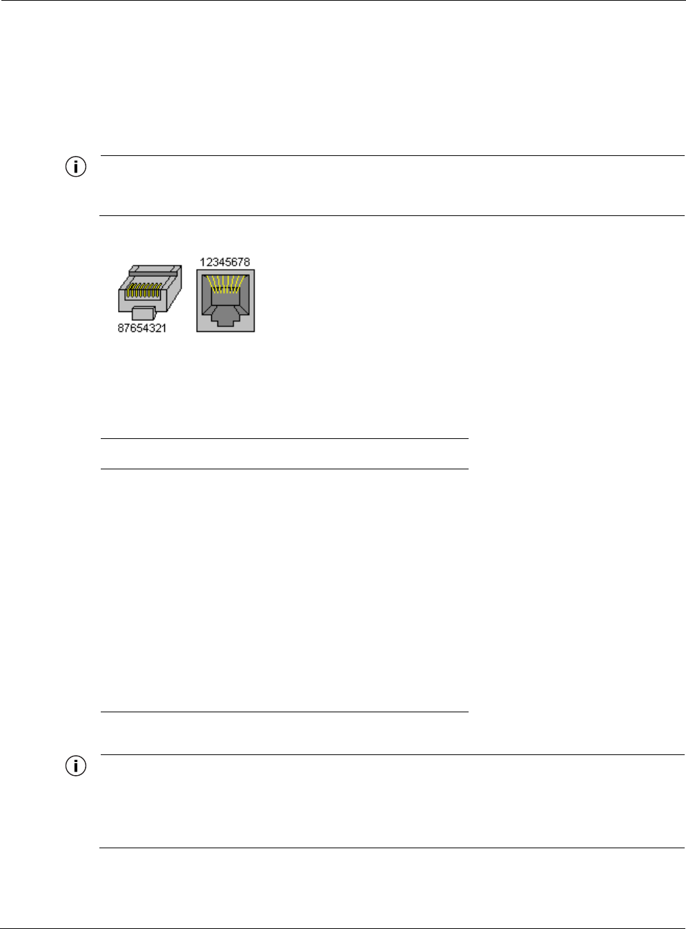
Connecting DC Power (Power over Ethernet)
Figure 13 shows the DC power connections for power over Ethernet, Figure 14 shows the pin
locations for the RJ45 connector, and Table 3 on page 23 gives the pin definitions. Make sure
that the Tropos 5110 Wi-Fi Cell is properly grounded before connecting power.
Note
Only use shield Cat5 cable rated for outdoor use. For protection against risk of fire, electrical
hazard and to ensure the reliable operation of this equipment, the shields of the Cat5 cable
must be properly terminated and bonded to the unit and to the protective earth (PE) at the
building entrance.
Note
National Electrical Codes (NEC) Article 800 requires the use of Agency Listed (UL/CSA)
Building Entrance Protector for all power and communications cables entering a building.
The NEC intends by Article 800 to protect the building and occupants from fires caused by
transient voltage and current surges.
Note
This unit may be powered by either an AC input or by a DC voltage supplied by Power Over
Ethernet Power Sourcing Equipment (PSE). When the unit is powered by the AC input a
24Vdc voltage is present on RJ45 connector pins 4,5(+) and 7,8 (-). When the unit is
powered by the DC Power Over Ethernet the DC input voltage is present on the RJ45
connector pins 4,5 and 7,8.
Warning
DC voltage on RJ-45 pins 4,5 (+) and 7,8 (-)
Note
This is not a mid-span powered device. Never attempt to daisy-chain Power Over Ethernet
devices.
Connecting Power
Outdoor Hardware Installation Guide 22
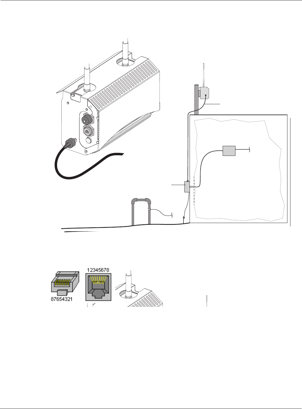
Figure 13 Connecting DC Power
Figure 14 RJ45 Pin Locations
fh
p
_046
Network Protection Unit
grounded to electrical ground rod
or water pipe
Data cable
Shielded cat5 cable to
Network Protection Unit
DC injector
Network
Shielded cat5 cable
(not included)
fh
p
_046
Network Protection Unit
grounded to electrical ground rod
or water pipe
Data cable
Shielded cat5 cable to
Network Protection Unit
DC injector
Network
Shielded cat5 cable
(not included)

Connecting Power
Outdoor Hardware Installation Guide 23
To connect a DC power source (power over Ethernet):
1. Verify that power is turned off on the designated circuits.
2. Run shielded Category 5 Ethernet cable appropriate for outdoor use from a network
protection unit (NPU) to the Tropos 5110 Wi-Fi Cell.
3. Connect one end of the Category 5 cable to the NPU. The NPU is IEEE/ANSI compliant and
suitable for outdoor use.
4. Connect the other end of the cable to the LAN or Management port on the Tropos 5110 Wi-
Fi Cell. Use a Field Attachable Ethernet connection (Tropos Networks EC003300) to
terminate the cable at the desired length.
5. Verify that the NPU is properly grounded.
6. Connect the NPU device to a DC power injector.
7. Reconnect the circuit and confirm that power to the Tropos 5110 Wi-Fi Cell comes on.
Note
This is not a mid-span powered device. Never attempt to daisy-chain Power Over Ethernet
devices.
Table 3 RJ45 Pin Descriptions
Pin Signal Description
1 TXD+ TX Data 10/100BaseT
2 TXD- TX Data 10/100BaseT
3 RXD+ RX Data 10/100BaseT
4 PoE+ Feeding power input 24 to 48 Vdc(+)
5 PoE+ Feeding power input 24 to 48 Vdc(+)
6 RXD- RX Data 10/100BaseT
7 PoE- Feeding power input 24 to 48 Vdc(-)
8 PoE- Feeding power input 24 to 48 Vdc(-)
Connecting Power
Outdoor Hardware Installation Guide 24
Connecting to AC Power (Category C)
Figure 15 shows the AC power connections for a Category C AC power source.
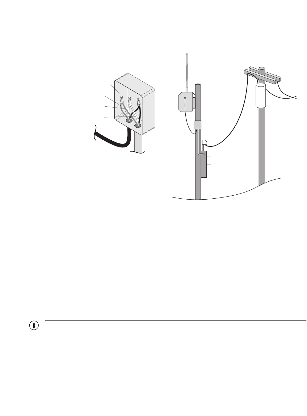
Figure 15 Connecting Category C AC Power
To connect an AC power source:
1. Verify that the service voltage is 120/208 VAC.
1. Verify that power is turned off on the designated circuits.
2. Install 1/2 inch liquid-tight conduit from the building entrance point to within 3 feet of the
outdoor system.
3. Run 3-wire AC service through the conduit.
4. Connect the conduit to a junction box. The conduit and junction box must be IEEE/ANSI
compliant and suitable for outdoor use.
Note
Data and power must never be enclosed in the same conduit.
5. Connect the 3-wire AC cable to the wires on the Tropos 5110 Wi-Fi Cell using wire nuts.
6. Connect the Tropos 5110 Wi-Fi Cell to a 120 or 208 VAC CAT C power source.
7. Reenergize the circuit and confirm that power to the Tropos 5110 Wi-Fi Cell comes on.
fhp_047
AC power
from meter
AC wiring in
junction box
To power
source
Green wire
Wire nuts
White wire
Black wire
To outdoor unit
Connecting Power
Outdoor Hardware Installation Guide 25
Note
The Tropos 5110 Wi-Fi Cell is equipped with additional AC surge protection and dual fuse
branch circuit protection. Additional ISA branch circuit protection is not required in the
upstream power distribution.
Connecting to Streetlight Power (Category C)
Figure 16 shows the power connections for Category C streetlight power. Use the 3-prong
NEMA twist-lock adapter with twist-lock style photoelectric controls for outdoor lighting
commonly used by utilities. The NEMA twist-lock adapter can be used only with UL 773 listed
outdoor lighting controls rated for and operated at 120/208 VAC.
Warning
Be extremely careful when connecting to Category C streetlight power.
Figure 16 Connecting Streetlight Power
fhp_049
AC power from
power adapter
on photosensor
AC power from
power adapter
on photosensor

Connecting a Data Port
Outdoor Hardware Installation Guide 26
Warning
Connect the outdoor system only to a twist-lock style outdoor lighting control powered by
120/208 VAC. Do not connect it to twist-lock style outdoor lighting controls powered by
higher voltage.
To connect a streetlight power source:
1. Verify that the service voltage is 120/208 VAC.
2. Verify that power is turned off on the designated circuits.
3. Remove the photosensor from the streetlight.
4. Connect the NEMA 3 prong plug from the Tropos 5110 Wi-Fi Cell to the photosensor
connector on the street light.
5. Connect the photosensor to the top of the NEMA 3 prong plug.
6. Connect the AC plug to the Tropos 5110 Wi-Fi Cell.
7. Reenergize the circuit and confirm that power to the Tropos 5110 Wi-Fi Cell comes on.
Note
The Tropos 5110 Wi-Fi Cell is equipped with additional AC surge protection and dual fuse
branch circuit protection. Additional ISA branch circuit protection is not required in the
upstream power distribution.
Note
Do not leave connectors open to the environment. Connectors should be covered with
closure caps when not in use. Closure caps should be tightened to be snug.
Connecting a Data Port
The Tropos 5110 Wi-Fi Cell is equipped with two RJ45 Ethernet ports. Use either port for the
wired connection to the Tropos 5110 Wi-Fi Cell gateway and to run DC power over Ethernet
(page 21). Use the Management port as the wired configuration interface. Use either port to
attach wired peripherals such as a traffic camera or IP networking device.
Note
The Tropos 5110 Wi-Fi Cell node comes pre-configured. For post-installation changes in
configuration, you can communicate with the node by way of its wireless connection. For
more information, see the Tropos Networks Configuration Guide.

Connecting a Data Port
Outdoor Hardware Installation Guide 27
Note
Only use shield Cat5 cable rated for outdoor use. For protection against risk of fire, electrical
hazard and to ensure the reliable operation of this equipment, the shields of the Cat5 cable
must be properly terminated and bonded to the unit and to the protective earth (PE) at the
building entrance.
Note
National Electrical Codes (NEC) Article 800 requires the use of Agency Listed (UL/CSA)
Building Entrance Protector for all power and communications cables entering a building.
The NEC intends by Article 800 to protect the building and occupants from fires caused by
transient voltage and current surges.
Note
This unit may be powered by either an AC input or by a DC voltage supplied by Power Over
Ethernet Power Sourcing Equipment (PSE). When the unit is powered by the AC input a
24Vdc voltage is present on RJ45 connector pins 4,5(+) and 7,8 (-). When the unit is
powered by the DC Power Over Ethernet the DC input voltage is present on the RJ45
connector pins 4,5 and 7,8.
Warning
DC voltage on RJ-45 pins 4,5 (+) and 7,8 (-)
Note
This is not a mid-span powered device. Never attempt to daisy-chain Power Over Ethernet
devices.
Connecting a Data Port
Outdoor Hardware Installation Guide 28
Figure 17 shows how to connect a data cable to the management and LAN ports.
Figure 17 Connecting a Data Port
To connect a DC power source (power over Ethernet):
1. Verify that power is turned off on the designated circuits.
2. Run shielded Category 5 Ethernet cable appropriate for outdoor use from a network
protection unit (NPU) to the Tropos 5110 Wi-Fi Cell.
3. Connect one end of the Category 5 cable to the NPU. The NPU is IEEE/ANSI compliant and
suitable for outdoor use.
4. Connect the other end of the cable to the LAN or Management port on the Tropos 5110 Wi-
Fi Cell. Use a Field Attachable Ethernet connection (Tropos Networks EC003300) to
terminate the cable at the desired length.
5. Verify that the NPU is properly grounded.
6. Connect the NPU device to a IEEE DC power injector.
7. Reconnect the circuit and confirm that power to the Tropos 5110 Wi-Fi Cell comes on.
fhp_050
Shielded cat5 cable
(not included)
Data connection
with watertight
plug
Network
Protection
Unit
fhp_050
Shielded cat5 cable
(not included)
Data connection
with watertight
plug
Network
Protection
Unit
Connecting Peripherals
Outdoor Hardware Installation Guide 29
Connecting Peripherals
If your Tropos 5110 Wi-Fi Cell is AC-powered, you can connect a peripheral to either of its
ports. 24V power is available on the unused electrical pair (rating 10 watts). Figure 18 shows the
pin locations for the RJ45 connector, and Table 4 shows the associated pin descriptions.
Note
Since peripheral connections require AC power, this configuration is not compatible with
power over Ethernet.
Figure 18 RJ45 Pin Locations
Note
Only use shield Cat5 cable rated for outdoor use. For protection against risk of fire, electrical
hazard and to ensure the reliable operation of this equipment, the shields of the Cat5 cable
must be properly terminated and bonded to the unit and to the protective earth (PE) at the
building entrance.
Table 4 RJ45 Pin Descriptions for Data Connection
Pin Signal Description
1 TXD+ TX Data 10/100BaseT
2 TXD- TX Data 10/100BaseT
3 RXD+ RX Data 10/100BaseT
4 PoE+ Feeding power output, 24 Vdc (+)
5 PoE+ Feeding power output, 24 Vdc (+)
6 RXD- RX Data 10/100BaseT
7 PoE- Feeding power output, 24 Vdc (-)
8 PoE- Feeding power output, 24 Vdc (-)

Outdoor Hardware Installation Guide 30
ASafety Information
This chapter describes important safety and service information for the outdoor system and
contains the following sections:
Safety Information for the Tropos 5110 Wi-Fi Cells
Service Instructions
Safety Information for the Tropos 5110 Wi-Fi Cells
The Federal Communications Commission (FCC) with its action in ET Docket 96-8 has adopted
a safety standard for human exposure to RF electromagnetic energy emitted by FCC certified
equipment. The Tropos 5110 products meet the uncontrolled environmental limits found in
OET-65 and ANSI C95.1, 1991. Proper operation of this radio according to the instructions
found in this manual and the hardware and software guides on the Tropos 5110 Wi-Fi Cells
result in user exposure that is substantially below the FCC recommended limits.
The following are guidelines to insure safe operation of the Tropos 5110 Wi-Fi Cells:
Do not touch or move the antenna(s) while the unit is transmitting or receiving.
Do not hold any component containing a radio such that the antenna is very close to or
touching any exposed parts of the body, especially the face or eyes, while transmitting.
Do not operate the radio or attempt to transmit data unless the antenna is connected;
otherwise, the radio may be damaged.
Use in specific environments:
Do not operate a portable transmitter near unshielded blasting caps or in an explosive
environment unless it is a type especially qualified for such use.
The use of wireless devices in hazardous locations is limited to the constraints posed by
the safety directors of such environments.
The use of wireless devices on airplanes is governed by the Federal Aviation
Administration (FAA).
The use of wireless devices in hospitals is restricted to the limits set forth by each
hospital.
Antenna use:
The Tropos 5110 Wi-Fi Cells must only be used with Tropos-approved components and
antennas.

Service Instructions
Outdoor Hardware Installation Guide 31
In order to comply with FCC RF exposure limits, dipole antennas should be located at a
minimum distance of 7.9 inches (20 cm) or more from the body of all persons.
High-gain, wall-mount or mast-mount antennas are designed to be professionally
installed and should be located at a minimum distance of 12 inches (30 cm) or more from
the body of all persons. Please contact your professional installer, VAR, or antenna
manufacturer for proper installation requirements.
Service Instructions
This section contains service information for the Tropos 5110 Wi-Fi Cells.
Note
The Tropos 5110 Wi-Fi Cells have no user serviceable parts inside. The following
information is intended for trained service personnel only.
Clock Battery
The Tropos 5110 Wi-Fi Cells have a real-time clock which is powered by a small lithium
rechargeable battery. If the real-time clock fails, return the unit to Tropos Networks for
servicing.
Caution
There is a danger of explosion if the battery is incorrectly replaced. Replace the battery
with only the same or equivalent type recommended by the manufacturer. Dispose of
used batteries according to the manufacturer’s instructions.
Fuses
The Tropos 5110 Wi-Fi cell uses two 20A, 250V, time delay type CC fuses.
To replace a fuse:
1. Turn off power to the Tropos 5110 Wi-Fi cell and remove the AC power plug.
2. Remove the screws that hold the metal fuse guard in place.
3. Unscrew the fuse cap, and replace the fuse.
4. Tightly fasten the screw cap.
5. Replace the power plug. Make sure that it is screwed in tightly.
6. Power on the Tropos 5110 Wi-Fi cell and confirm that the power light comes on.
7. Replace the metal fuse guard.

Service Instructions
Outdoor Hardware Installation Guide 32
Caution
For continued protection against risk of fire, replace only with the same type and rating
of fuse.
Caution
The Tropos 5110 Wi-Fi cell has dual fusing.
Warning
DC voltage on RJ-45 pins 4,5 (+) and 7,8 (-)

Outdoor Hardware Installation Guide 36
BProduct Specifications
Table B-1 Physical Specifications
Physical Dimensions Height Width Depth
Inches 8.5 13.0 7
Centimeters 21.59 33.02 17.78
Weight
lbs - maximum 19
Kg - maximum 7.1
Mounting Pole Diameter 1.75” to 10”
Temperature Min Max
Operating Range -35C 55C
Storage Range -40C 85C
Weather Rating Rainproof per UL50
Color Gloss white

Outdoor Hardware Installation Guide 37
Table B-2 Interfaces
Data Interface Distance (km) Connector
IEEE 802.3 10/100BaseT 0.37 (10BaseT Duplex
Setting) Weathertight
RJ45
Management Interface Distance (km) Connector
IEEE 802.3 10/100Base T 0.37 (10BaseT Duplex
Setting) Weathertight
RJ45
Wireless Interface
Standard IEEE 802.11b Wi-Fi
Frequency Range 2400 to 2485 MHz ISM Band
Modulation DSSS; DBPSK @ 1 Mbps,
DQPSK @ 2 Mbps,
CCK @ 5.5 and 11 Mbps
TX Power 28dBm
EIRP 36 dBm (7.4dBi omni
antennas)
RX Sensitivity (1Mbps) -94dBm
Antennas External
Antenna Pattern 7.4 dBi omni
Antenna Diversity Receive
Impedance 50 ohms
VSWR 1.5 : 1
Connector N (female)
Indicator - Status Lamp Red/Green

Outdoor Hardware Installation Guide 38
Table B-3Power Options / Consumption
Power Over Ethernet (POE) 24 to 48 Vdc/1A maximum 14W/19W typical/max
Single Phase VAC IEEE/ANSI
C62.41 CAT C Power 120, 208 VAC 28W/238W typical/max
Protection Circuits
Antenna Protection <= 0.5µJ for 3kA @ 8/20µS
Waveform
EN61000-4-5 Level 4 Surge
Immunity
VAC Surge Protection IEEE/ANSI C62.41 Category C
10kA @ 8/20uS Waveform; 36kA
per phase L-L, L-N, L-PE
EN61000-4-5 Level 5 Surge
Immunity
UL1449 2nd Edition Recognized
Integrated Branch Circuit
Protection Class CC-Fuse Protection:
Littlefuse KLDR Time-Delay 20A
Data Port Protection EN61000-4-2 Level 4 ESD
Immunity
EN61000-4-5 Level 4 Surge
Immunity

Outdoor Hardware Installation Guide 39
Table B-4 Certifications, Other
Certifications CFR 47 FCC Part 15.C; Class A
UL 60950 Listed I.T.E.
CAN/CSA-C22.2 60950-00
UL 50 IEC 60664-1 Rated for Outdoor Use
CAN/CSA-C22.2 60950-00
UL 1449 IEC 60529
EN61000-4-5 Level 4 AC Surge Immunity
EN61000-4-2 Level 4 ESD Immunity
EN61000-4-4 Level 4 EFT Burst Immunity
EN61000-4-3 EMC Field Immunity
Wind
Survivability > 160 mph
Wind Loading
(160 mph) < 1024 newtons

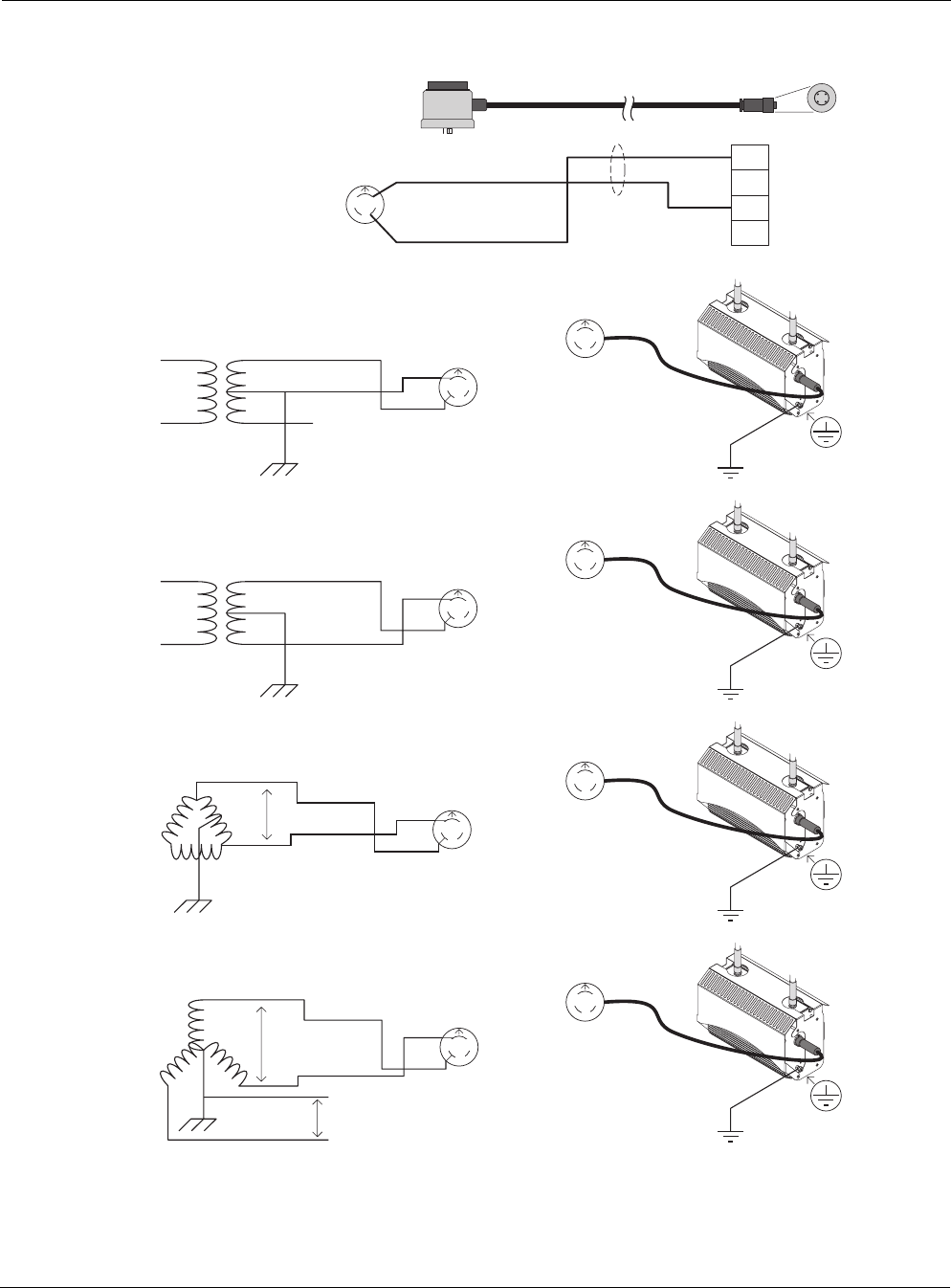
Outdoor Hardware Installation Guide 41
Figure 19 AC Wiring — Photoelectric Power Tap
PE
White Length: 4' or 20'
PT020004 (4') or PT020020 (20')
Photoelectric Power-Tap
Power Input Cable
2Wire - 120/208/240Vac
NEMA Plug - UL Standard 773
Plug-in locking type for
photocontrols in use with
area lighting
Carol P-7K-123033 MSHA
Amphenol
T3109-001
16/2 SOOW
North
Black
L2 / N
L1
3
2
1
240Vac three phase; two wire service (Delta)
L1
Black
White
Protective Earth
L2
240Vac
NEMA Photoelectric
Control / UL773
(female)
NEMA Photoelectric
Control / UL773
Power-Tap Adapter
(male)
Input Power Cable
PT020004 or
PT020020
North
L1
L2
North
Tropos
Outdoor Unit
fhp_052
Power-Tap 120Vac single phase; two wire service
L1 Black
White
Protective Earth
L2 NEMA Photoelectric
Control / UL773
(female)
NEMA Photoelectric
Control / UL773
Power-Tap Adapter
(male)
Input Power Cable
PT020004 or
PT020020
North
White
N
White
L2
Black
L1
Black
L1
L1
N
North
Tropos
Outdoor Unit
Power-Tap 240Vac single phase; two wire service
L1 Black
Red
Protective Earth
L2
NEMA Photoelectric
Control / UL773
(female)
NEMA Photoelectric
Control / UL773
Power-Tap Adapter
(male)
Input Power Cable
PT020004 or
PT020020
North
White
L2
Black
L1
L1
L2
North
Tropos
Outdoor Unit
208Vac three phase; two wire service (grounded-Wye)
L1
Black
Red
Protective Earth
L2
208Vac
NEMA Photoelectric
Control / UL773
(female)
NEMA Photoelectric
Control / UL773
Power-Tap Adapter
(male)
Input Power Cable
PT020004 or
PT020020
North
L1
L2
120Vac
North
Tropos
Outdoor Unit
White
L2
Black
L1
N
L3
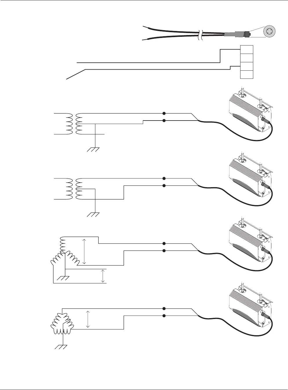
Outdoor Hardware Installation Guide 42
Figure 20 AC Wiring Category C
PE
PT230025 Overvoltage Category 3 or
IEEE/ANSI C62.41 Category C
Power Electrical Service Cable
2Wire - 120/208/240Vac
For Aerial, Duct, Raceway or Direct Burial Secondary Power Supply
Rome Cable Series 2150
XLPE 10 AWG 7 strand 600V
Amphenol
T3109-001
L1
Black
L2 / N
White
3
2
1
fhp_054
120Vac single phase; two wire service
L1
Neutral
Black
White
Black (L1)
Black (L2)
Protective Earth
L2
Input Power Cable
PT230025
Tropos
Outdoor Unit
240Vac single phase; two wire service
L1 Black
Red
Black (L1)
Black (L2)
Protective Earth
L2
Input Power Cable
PT230025
Tropos
Outdoor Unit
208Vac three phase; two wire service (grounded-Wye)
Black
White
Black (L1)
Black (L2)
Input Power Cable
PT230025
Tropos
Outdoor Unit
L1
Protective Earth
L2
208Vac
120Vac
N
L3
240Vac three phase; two wire service (Delta)
Black
Red
Black (L1)
Black (L2)
Input Power Cable
PT230025
Tropos
Outdoor Unit
L1
Protective Earth
L2
240Vac
Length: 25'

Outdoor Hardware Installation Guide 43
Index
A
AC wiring diagrams 40
antenna options 4
antenna type and placement 4
antennas
cable-attached 13
connecting 13
waterproofing 15
B
building materials 4
C
cable-attached antennas 13
categories of power 19
connecting
AC power 20
antennas 13
category III AC power 24
DC power 21
power 18
connecting a data port 26
connecting peripherals 29
D
data port
connecting 26
data rate considerations 4
DC power 21
distance limits 3
distance lmits 3
diversity 4
E
Ethernet 21
F
fuses 31
G
ground
connecting 17, 18
I
installation considerations
antenna options 4
site surveys 4
installation hardware and tools 3
L
location guidelines 3
M
model numbers 1
mounting
to a pole 6, 8
to a streetlight pole 10
mounting instructions 5
O
obstructions 4
P
peripherals
connecting 29
physical environment 4
pole mounting 6
power
categories 19
connecting 18
connecting category III AC power 24
connecting DC power 21
connecting streetlight power 25
power over Ethernet 21
power sources
overview 4
preparing for installation 1
product specifications 36
S
safety
general considerations 5
safety information for the wireless router 30
service instructions 31
site planning 3
site surveys 4
