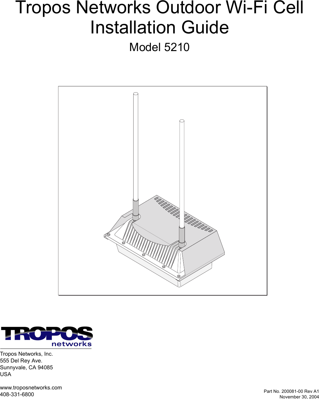
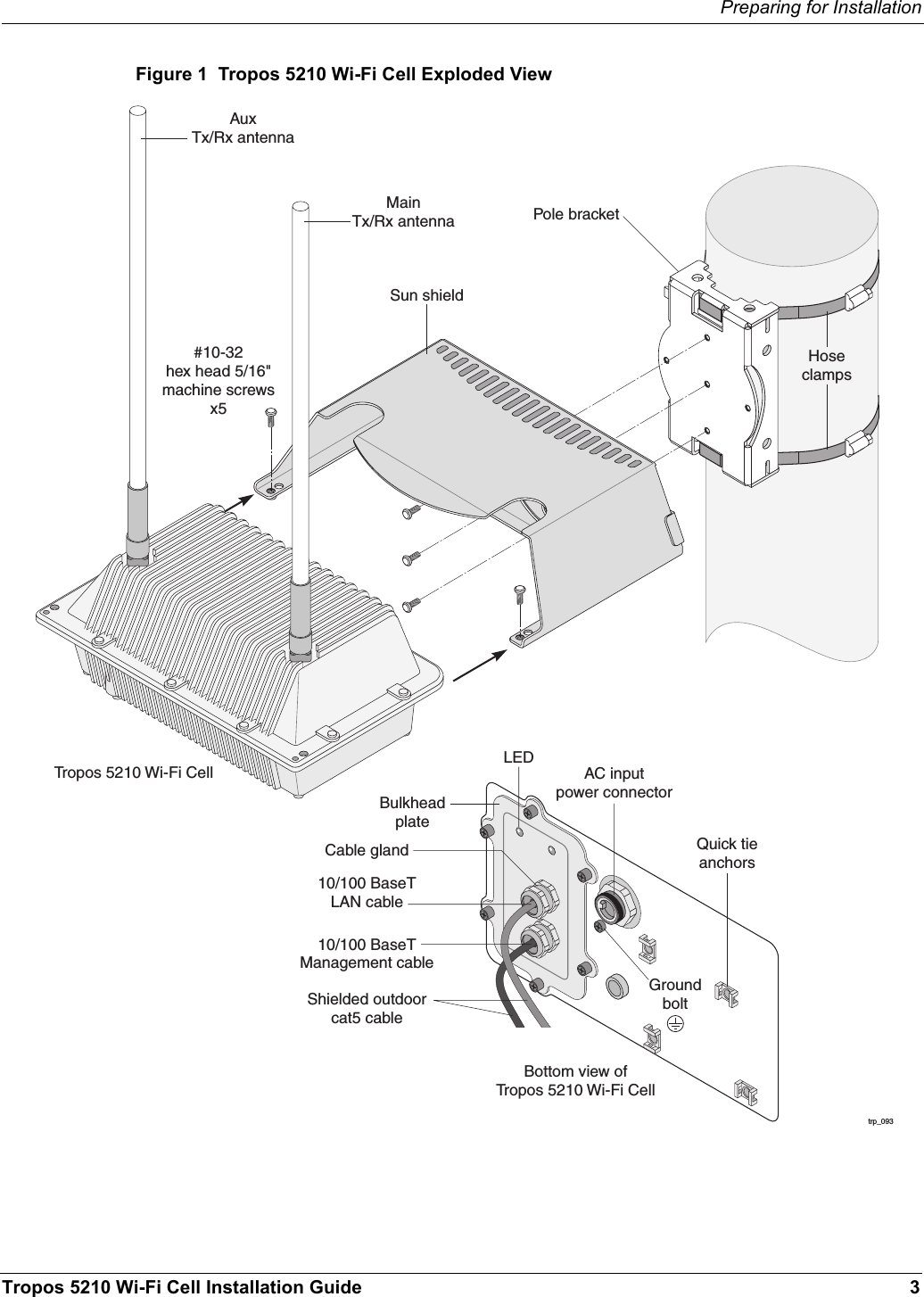
ABB Enterprise Software 52101000 802.11b/g Outdoor Wi-Fi Cellular Base Station User Manual Outdoor Unit Guide

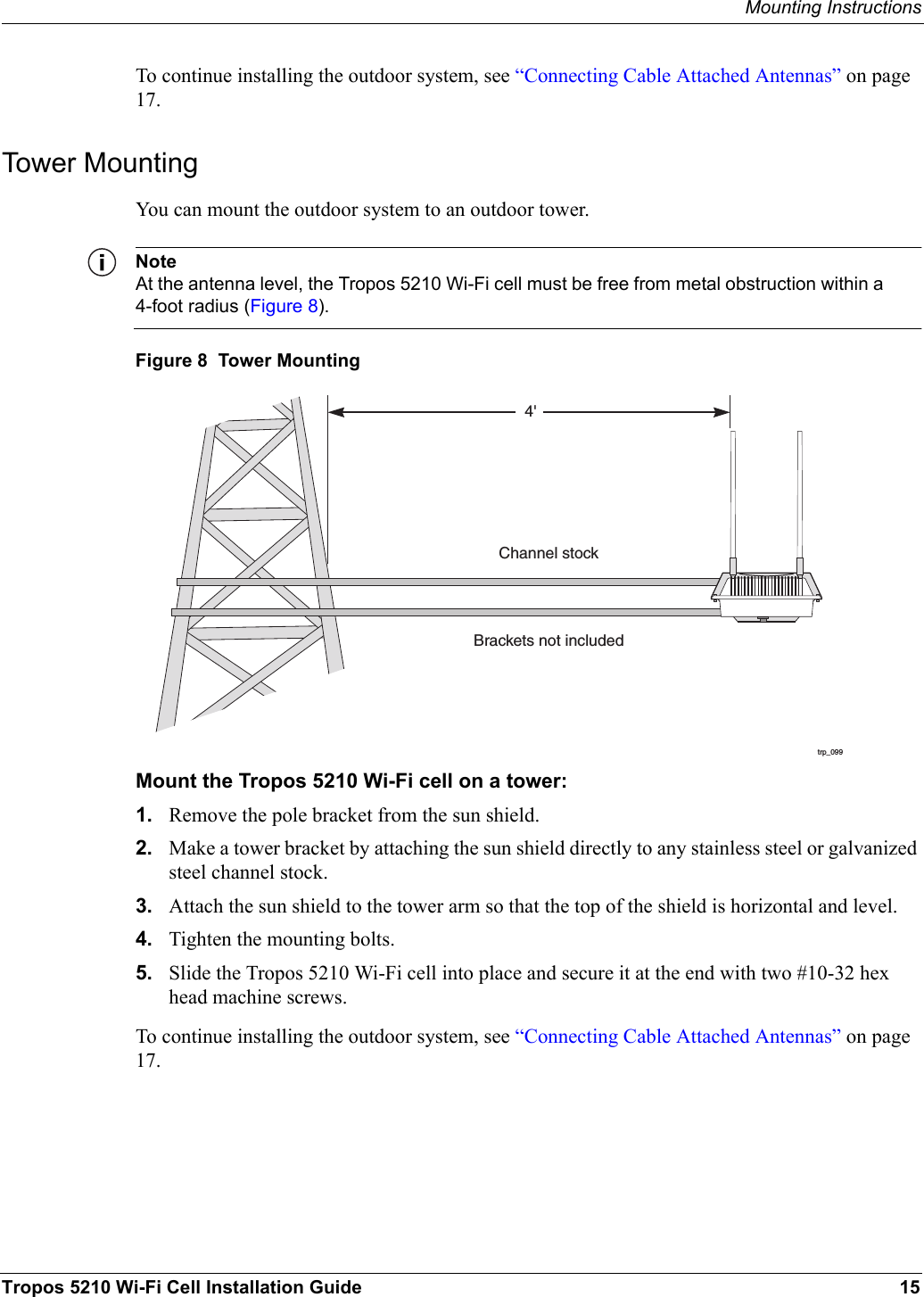
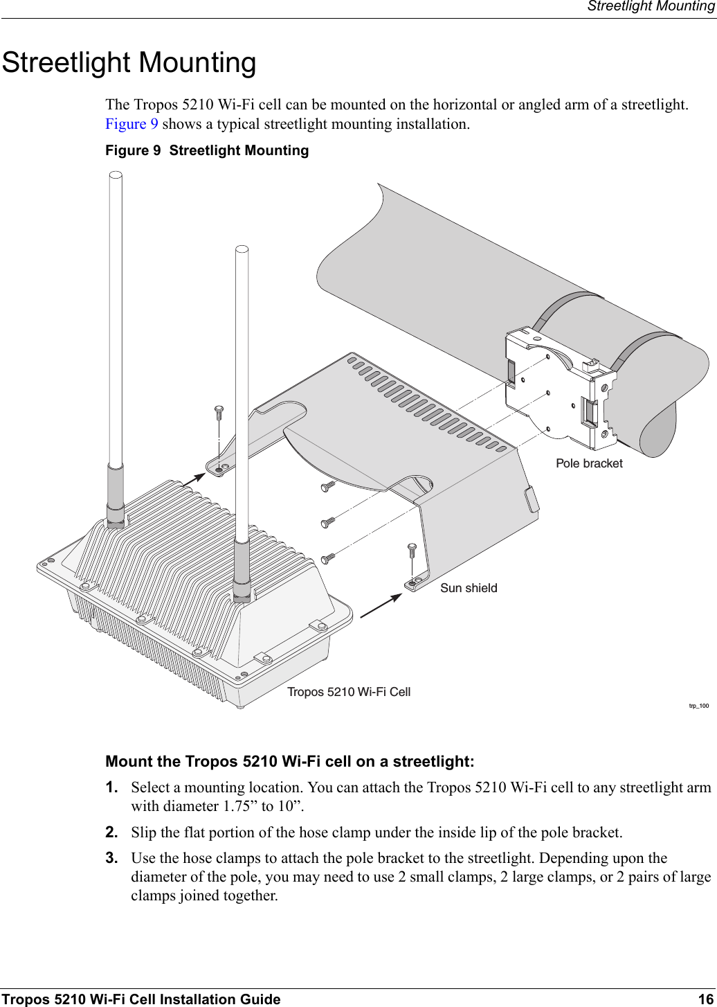
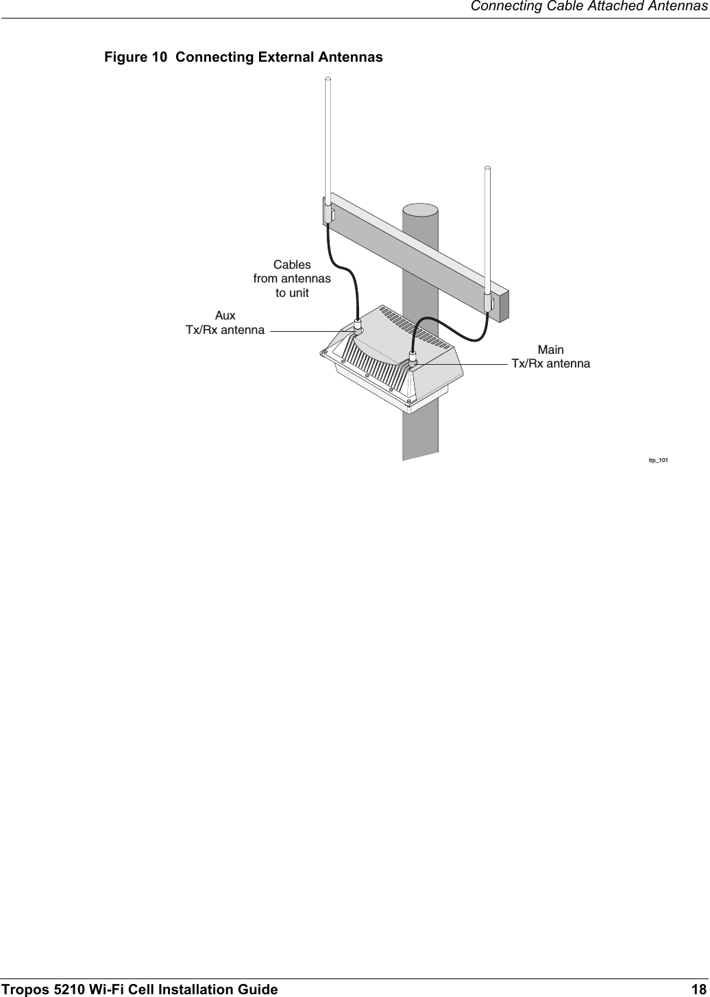
Tropos Networks, Inc. 802.11b/g Outdoor Wi-Fi Cellular Base Station Outdoor Unit Guide

User Manual

Part No. 200081-00 Rev A1November 30, 2004Tropos Networks Outdoor Wi-Fi CellInstallation GuideModel 5210Tropos Networks, Inc.555 Del Rey Ave.Sunnyvale, CA 94085USAwww.troposnetworks.com408-331-6800
Tropos 5210 Wi-Fi Cell Installation Guide iiCopyright Notice©2004 Tropos Networks, Inc. All rights reserved. Tropos Networks is a registered trademark of Tropos Networks, Inc. in the United States and certain other jurisdictions. Specifications are subject to change without notice.Loctite is a registered trademark of Loctite Corporation, USA.FCC Notice to Users and OperatorsThis equipment has been tested and found to comply with the limits for a Class B digital device, pursuant to Part 15 of the FCC Rules. These limits are designed to provide reasonable protection against harmful interference when the equipment is operated in a commercial environment. This equipment generates, uses, and can radiate radio frequency energy and, if not installed and used in accordance with the instruction manual, may cause harmful interference to radio communications. Operation of this equipment in a residential area is likely to cause harmful interference, in which case the user will be required to correct the interference at his own expense. If this equipment does cause interference to radio or television reception, which can be determined by turning the equipment off and on, the user is encouraged to correct the interference by using one of the following measures:Reorient or relocate the receiving antenna. Increase separation between the equipment and receiver. Connect the equipment to an outlet on a circuit different from that to which the receiver is connected. Consult the dealer or an experienced radio/TV technician.This Part 15 radio device operates on a non-interference basis with other devices operating at this frequency. Any changes or modification to said product not expressly approved by Tropos Networks could void the user's authority to operate this device.VCCI Notice to Users and OperatorsTranslation: This is a Class B product based on the standard of the Voluntary Control Council for Interference by Information Technology Equipment (VCCI). If this equipment is used in a Japanese domestic environment, radio disturbance may arise. When such trouble occurs, the user may be required to take corrective actions.
Tropos 5210 Wi-Fi Cell Installation Guide iiiTaiwan DGT Telecommunications Act Notice to Users and OperatorsWarningIt is illegal to modify the construction of this product. Modifying the operating frequency or enhancing the transmit output power through the use of external amplifiers or other equipment is specifically disallowed by the “Telecommunications Act.”WarningThis device is for outdoor or indoor use with conditions that no harmful interference to authorized radio stations results from the operation of this device. This device shall not influence aircraft security and/or interfere with legal communications as defined in the “Telecommunications Act.” If this device is found to cause interference, the operator of this equipment shall cease operating this device immediately until no interference is achieved. NoteThis device must be installed by trained professional, value added reseller or systems integrator who is familiar with RF cell planning issues and the regulatory limits defined by the Taiwan government “Telecommunications Act” for RF exposure, specifically those limits outlined in Telecom Technical Regulations RTTE01 and LP002.低功率電波輻性電機管理辦法第十四條經型式認證合格之低功率射頻電機,非經許可,公司、商號或使 用者均不得擅自變更頻率、加大功率或變更原設計之特性及功能。 第十七條低功率射頻電機之使用不得影響飛航安全及干擾合法通信;經發 現有干擾現象時,應立即停用,並改善至無干擾時方得繼續使用。 前項合法通信,指依電信規定作業之無線電信。低功率射頻電機須忍受合法通信 或工業、科學及醫療用電波輻射性電機設備之干擾。
Tropos 5210 Wi-Fi Cell Installation Guide ivSTOP!! STOP!! STOP!! STOP!!READ THIS FIRST!WarningYou can be killed installing this device!You can be killed if the cell antennas come near electric power lines. Carefully read and follow all instructions in this manual. By nature of the installation, you may be exposed to hazardous environments and high voltage. Use caution when installing the outdoor system.CautionThe Tropos 5210 Outdoor Wi-Fi cell may contain a lithium-ion battery. To avoid the possibility of an explosion, the Tropos 5210 Wi-Fi cell should NOT be exposed to any temperatures higher than 85 degrees C. The RJ45 connectors of your Tropos 5210 Outdoor Wi-Fi cell may source DC power on pins 4,5 and 7,8. The IEEE 802.3 standards allow for pins 4,5 and 7,8 to be used for Power Over Ethernet. Some products may be incompatible with the Tropos Power Over Ethernet capability. If such problems occur, make sure that the unit is configured with the Power Over Ethernet capability set to Off (default setting). If problems persist, use Ethernet cables that have no connections to the unused pins 4,5 and 7,8.The Tropos 5210 Outdoor Wi-Fi cell is installed in wet, outdoor locations. Make sure closure caps are installed and all cable connections are securely fastened and waterproofed.The Tropos 5210 Outdoor Wi-Fi cell can only be used with approved antennas. See Appendix C, “Approved Antenna Configurations”  for further information.
Tropos 5210 Wi-Fi Cell Installation Guide vContentsInstalling the Tropos 5210 Wi-Fi Cell . . . . . . . . . . . . . . . . . . . . . . . . . . . . .  1Preparing for Installation  . . . . . . . . . . . . . . . . . . . . . . . . . . . . . . . . . . . . .  2Model Numbers. . . . . . . . . . . . . . . . . . . . . . . . . . . . . . . . . . . . . . . . . . .  2Installation Hardware and Tools . . . . . . . . . . . . . . . . . . . . . . . . . . . . . .  4Site Planning. . . . . . . . . . . . . . . . . . . . . . . . . . . . . . . . . . . . . . . . . . . . .  4Location Guidelines  . . . . . . . . . . . . . . . . . . . . . . . . . . . . . . . . . . . . . . .  5Antenna Options . . . . . . . . . . . . . . . . . . . . . . . . . . . . . . . . . . . . . . . . . .  5Site Surveys . . . . . . . . . . . . . . . . . . . . . . . . . . . . . . . . . . . . . . . . . . . . .  6Power Source . . . . . . . . . . . . . . . . . . . . . . . . . . . . . . . . . . . . . . . . . . . .  7Safety . . . . . . . . . . . . . . . . . . . . . . . . . . . . . . . . . . . . . . . . . . . . . . . . . .  7Mounting Strategies . . . . . . . . . . . . . . . . . . . . . . . . . . . . . . . . . . . . . . . . .  8Proper Use of Hose Clamps. . . . . . . . . . . . . . . . . . . . . . . . . . . . . . . . . . .  9Mounting Instructions . . . . . . . . . . . . . . . . . . . . . . . . . . . . . . . . . . . . . . .  11Metal Pole Mounting . . . . . . . . . . . . . . . . . . . . . . . . . . . . . . . . . . . . . .  12Wood Pole Mounting. . . . . . . . . . . . . . . . . . . . . . . . . . . . . . . . . . . . . .  14Tower Mounting  . . . . . . . . . . . . . . . . . . . . . . . . . . . . . . . . . . . . . . . . .  15Streetlight Mounting . . . . . . . . . . . . . . . . . . . . . . . . . . . . . . . . . . . . . . . .  16Connecting Cable Attached Antennas . . . . . . . . . . . . . . . . . . . . . . . . . .  17Waterproofing Antenna Connections . . . . . . . . . . . . . . . . . . . . . . . . .  19Installing Customer-Provided Antenna . . . . . . . . . . . . . . . . . . . . . . . .  20Grounding the Tropos 5210 Wi-Fi cell . . . . . . . . . . . . . . . . . . . . . . . . . .  22Grounding the Data Protection Device . . . . . . . . . . . . . . . . . . . . . . . .  23Connecting Power  . . . . . . . . . . . . . . . . . . . . . . . . . . . . . . . . . . . . . . . . .  24Categories of Power . . . . . . . . . . . . . . . . . . . . . . . . . . . . . . . . . . . . . .  24Connecting to AC Power (Category C). . . . . . . . . . . . . . . . . . . . . . . .  27Connecting to Streetlight Power (Category C) . . . . . . . . . . . . . . . . . .  28Connecting a Data Port  . . . . . . . . . . . . . . . . . . . . . . . . . . . . . . . . . . . . .  30Resetting the Cell . . . . . . . . . . . . . . . . . . . . . . . . . . . . . . . . . . . . . . . . . .  34Connecting Peripherals  . . . . . . . . . . . . . . . . . . . . . . . . . . . . . . . . . . . . .  35Battery Backup Operation  . . . . . . . . . . . . . . . . . . . . . . . . . . . . . . . . . . .  38Safety Information for the Tropos 5210 Wi-Fi Cells . . . . . . . . . . . . . . . .  38Service Instructions  . . . . . . . . . . . . . . . . . . . . . . . . . . . . . . . . . . . . . . . .  39A Power Consumption  ............................................................................ 41B Product Specifications  ........................................................................ 42
Tropos 5210 Wi-Fi Cell Installation Guide viC Approved Antenna Configurations ..................................................... 47U.S. Antenna Configurations and Ordering Information. . . . . . . . . . . . .  47Japanese Antenna Configurations and Ordering Information  . . . . . . . .  49D Installation Accessories  ...................................................................... 50E AC Wiring Diagrams.............................................................................. 52F Wind Loading Considerations  ............................................................ 55Index ......................................................................................................  56
Tropos 5210 Wi-Fi Cell Installation Guide 1Installing the Tropos 5210 Wi-Fi CellThis guide explains how to install the Tropos 5210 Wi-Fi cell safely and is intended for trained technical professionals. It covers the following topics:Preparing for InstallationMounting StrategiesProper Use of Hose ClampsMounting InstructionsConnecting Cable Attached AntennasGrounding the Tropos 5210 Wi-Fi cellConnecting PowerConnecting a Data PortConnecting PeripheralsSafety Information for the Tropos 5210 Wi-Fi CellsService Instructions
Preparing for InstallationTropos 5210 Wi-Fi Cell Installation Guide 2Preparing for InstallationThe Tropos 5210 Wi-Fi cell must be installed by a trained professional, value added reseller, or systems integrator who is familiar with RF cell planning issues and regulatory limits defined by the governing body of the country in which the unit will be installed. This section lists the required equipment and model numbers and explains how to prepare the installation site.Model NumbersAn exploded view of the Tropos 5210 Wi-Fi cell assembly is shown in the next figure. NoteAntenna(s) must be installed by a trained professional. Operating the unit with non-qualified antennas is a violation of U.S. FCC Rules Part 15.203(c), Code of Federal Regulations, Title 47. See Appendix C, “Approved Antenna Configurations,” for a listing of antenna options.WarningIt is illegal to modify the construction of this product. Modifying the operating frequency or enhancing the transmit output power through the use of external amplifiers or other equipment is specifically disallowed by the Taiwan DGT “Telecommunications Act.”WarningThis device is for outdoor or indoor use with conditions that no harmful interference to authorized radio stations results from the operation of this device. This device shall not influence aircraft security and/or interfere with legal communications as defined in the Taiwan DGT “Telecommunications Act.” If this device is found to cause interference, the operator of this equipment shall cease operating this device immediately until no interference is achieved.
Preparing for InstallationTropos 5210 Wi-Fi Cell Installation Guide 3Figure 1  Tropos 5210 Wi-Fi Cell Exploded Viewtrp_09310/100 BaseTLAN cable#10-32hex head 5/16"machine screwsx5AC inputpower connectorPole bracket10/100 BaseTManagement cableShielded outdoorcat5 cableCable glandAuxTx/Rx antennaTropos 5210 Wi-Fi CellSun shieldMainTx/Rx antennaHoseclampsGroundboltLEDBulkheadplateBottom view ofTropos 5210 Wi-Fi CellQuick tieanchors
Preparing for InstallationTropos 5210 Wi-Fi Cell Installation Guide 4Installation Hardware and ToolsTropos Networks provides the following accessories to install the Tropos 5210 Wi-Fi cell:One pole bracketOne sun shieldTwo 4-inch diameter hose clampsFour 6-inch diameter hose clampsFive 5/16-inch #10-32 stainless steel hex head machine screwsYou must supply the following tools:5/16-inch nut driver1/4-inch flat blade screwdriverTower mounting only: supply stainless or galvanized steel channel stock and 1/2-inch or 5/8-inch nuts, bolts, and washers to connect to the tower arm.Wood pole mounting only: two 5/8-inch diameter, 3-inch long lag boltsSite PlanningTo ensure safe and durable wiring, installation of the Tropos 5210 Wi-Fi cell must follow appropriate electrical and building codes. Follow the National Electrical Code (NEC) requirements, unless local codes in your area take precedence over the NEC code. The following distance limits apply to installations that have 10/100 Base-T Category 5 network cables attached to the Tropos 5210 Wi-Fi cell:300 feet between devices for 100BaseT operation1300 feet for 10BaseT operation. The Ethernet duplex and speed setting is configurable.NoteNational Electrical Codes (NEC) Article 800 requires the use of Agency Listed (UL/CSA/TUV) Building Entrance Protector for all power and data communications cables entering a building. The NEC intends by Article 800 to protect the building and occupants from fires caused by transient voltage and current surges. NoteEthernet data cable installations having lengths greater than 140 feet in the outdoor environment must use a UL497 approved (UL/CSA/TUV Listed) primary protection device at the building entrance. Ethernet data cable installations having lengths less than 140 feet in the outdoor environment may use a UL497A (UL/CSA/TUV Listed) secondary protection device at the building entrance. Tropos Data Protection Device and Network Protection Units are UL497A secondary protection devices.
Preparing for InstallationTropos 5210 Wi-Fi Cell Installation Guide 5Location GuidelinesThe Tropos 5210 Wi-Fi cell is a radio device and therefore susceptible to interference that can reduce throughput and range. Follow these guidelines to ensure the best performance:Install the unit in an area where trees, buildings, and large steel structures do not obstruct radio signals to and from the antenna. Direct line-of-sight operation is best. Install the unit away from microwave ovens or other devices operating in the 2.4 GHz frequency range. Install the units away from other possible sources of 2.4 GHz WLAN interference, such as cordless phones, home spy cameras, frequency hopping (FHSS) and DSSS LAN transceivers (non-802.11b), electronic news gathering video links, radars, amateur radios, land mobile radio services, local government sites (such as law enforcement), fixed microwave services, local TV transmission and private fixed point transmitters.Antenna OptionsYou can purchase the Tropos 5210 Wi-Fi cell with an integrated omni-directional antenna, or use an approved external antenna. Omni-directional antennas are best for systems requiring a signal distribution in more than one direction. To comply with regulatory RF exposure limits, locate antennas a minimum distance of 7.9 inches (20cm) from people. For antenna model numbers, refer to Appendix B, “Product Specifications.”NoteAntenna(s) must be installed by a trained professional. Operating the unit with non-qualified antennas is a violation of U.S. FCC Rules Part 15.203(c), Code of Federal Regulations, Title 47. See Appendix C, “Approved Antenna Configurations,” for a listing of antenna options.WarningIt is illegal to modify the construction of this product. Modifying the operating frequency or enhancing the transmit output power through the use of external amplifiers or other equipment is specifically disallowed by the Taiwan DGT “Telecommunications Act.”WarningThis device is for outdoor or indoor use with conditions that no harmful interference to authorized radio stations results from the operation of this device. This device shall not influence aircraft security and/or interfere with legal communications as defined in the Taiwan DGT “Telecommunications Act.” If this device is found to cause interference, the operator of this equipment shall cease operating this device immediately until no interference is achieved.
Preparing for InstallationTropos 5210 Wi-Fi Cell Installation Guide 6Site SurveysDue to variations in component configuration, placement, and physical environment, each installation is unique. Before installing the Tropos 5210 Wi-Fi cell, perform a site survey to determine the optimum placement of units for maximum range, coverage, and network performance. Consider the following factors when performing a site survey:Data rates—Sensitivity and range are inversely proportional to data bit rates. The maximum radio range is achieved at the lowest workable data rate. A decrease in receiver threshold sensitivity occurs as radio data rate increases. Antenna type and placement—Proper antenna configuration is a critical factor in maximizing radio range. As a general rule, range increases in proportion to antenna height and gain. Physical environment—Clear or open areas provide better radio range than closed or filled areas. The less cluttered the operating environment, the greater the range. Obstructions—A physical obstruction, such as a building or tree, can block or hinder communication. Avoid locating antennas in a location where there is an obstruction between sending and receiving devices. Building materials—Radio penetration is influenced by the building material used in construction. For example, drywall construction permits greater range than concrete blocks. Diversity—The Tropos 5210 Wi-Fi cell supports transmit and receive diversity, which requires two antennas.
Preparing for InstallationTropos 5210 Wi-Fi Cell Installation Guide 7Power SourceThe Tropos 5210 Wi-Fi cell supports two options for connecting to a power source:AC power source (3-wire service) — 3W(P+N+PE) or 3W(2P+PE); 90-480 VAC, 50/60 Hz NEMA plug, for streetlight photoelectric control power tap (2-wire service) —2W(2P) or 2W(P+N); 90-480 VAC 50/60 HzWarningConnect the AC powered outdoor system only to 90-480 VAC power sources. Do not connect it to a power source of higher voltage.CautionYou must install an external grounding wire if the Tropos 5210 Wi-Fi cell is installed on a non-metal pole or if the metal installation structure is not properly grounded. You must also ground the outdoor data protection device to a bonded pipe or ground rod. Make sure that grounding is complete before you connect power to the Tropos 5210 Wi-Fi cell.SafetyInstalling the Tropos 5210 Wi-Fi cell can pose a serious hazard. Be sure to take precautions to avoid the following:Exposure to high voltage lines during installationFalls when working at heights or with laddersInjuries from dropping tools and equipmentContact with AC wiring
Mounting StrategiesTropos 5210 Wi-Fi Cell Installation Guide 8Mounting StrategiesWhen choosing mounting locations, consider the available mounting structures and antenna clearance. The Tropos 5210 Wi-Fi cell should always be mounted with the top of the cell horizontal and level and with the antennas facing upward.It is usually best to attach ground and data cables to the cell prior to mounting. Before mounting the cell, review the wiring instructions in “Grounding the Tropos 5210 Wi-Fi cell” on page 22 and “Connecting a Data Port” on page 30 to determine the best strategy for the selected location.NoteSince the mounting structure itself is a potential obstruction, the cell should be mounted with at least 4 feet of clearance between the antennas and the mounting structure.Acceptable options for mounting on a streetlight are shown in Figure 2. In each case the cell is mounted to assure clearance for the antennas above the height of the streetlight.Figure 2  Example Mounting Location - Antennas Facing Upwardtrp_094Antennas clear of obstructionAntennas clearof obstruction
Proper Use of Hose ClampsTropos 5210 Wi-Fi Cell Installation Guide 9Proper Use of Hose ClampsThe mounting assembly for the Tropos 5210 Wi-Fi cell contains hose clamps to secure the cell to the mounting structure. Figure 3 illustrates the proper use of the hose clamps when mounting on large poles (≥ 8 inches). The clamps are routed through holes in the pole bracket as shown in the figure, and then attached to the pole and tightened.Figure 3  Proper Use of Hose Clamps - Large Poles (>= 8 Inches)trp_095Band goesthrough slotsHose clampor steel bandingplacementfor larger polesSun shield >= 8 inches
Proper Use of Hose ClampsTropos 5210 Wi-Fi Cell Installation Guide 10The proper use of the hose clamps for small poles (< 8 inches) is shown in Figure 4. The clamps are routed behind the inner tabs in the pole bracket, and then attached to the pole and tightened.Figure 4  Proper Use of Hose Clamps - Small Poles (< 8 Inches)trp_096Hose clampplacementfor smaller polesBand goesbehindinner tabsSun shield
Mounting InstructionsTropos 5210 Wi-Fi Cell Installation Guide 11Mounting InstructionsThis section explains how to mount the Tropos 5210 Wi-Fi cell on a pole, tower, or streetlight. It is best to mount the Tropos 5210 Wi-Fi cell to aluminum or galvanized steel structures. The mounting brackets are designed to pierce any oxidation layers that are on the outside of the pole, thereby assuring good quality connection to the grounded structure.NoteThe Tropos 5210 Wi-Fi cell should always be mounted with the top of the cell horizontal and level and with the antennas facing upward.NoteIt is best to attach ground and data cables to the cell before sliding the cell into the mounted sun shield, as explained in this section. Before mounting the cell, review the wiring instructions in “Grounding the Tropos 5210 Wi-Fi cell” on page 22 and “Connecting a Data Port” on page 30 to determine the best strategy for the selected location.NoteMounting to wood, concrete, or painted poles may require primary grounding for the unit. Check the national electrical codes in your area for specific rules.
Mounting InstructionsTropos 5210 Wi-Fi Cell Installation Guide 12Metal Pole MountingFigure 5 illustrates the proper method of mounting the Tropos 5210 Wi-Fi cell on an outdoor metal pole. Figure 5  Metal Pole MountingMount the Tropos 5210 Wi-Fi cell on a metal pole:1. Select a mounting location. You can attach the Tropos 5210 Wi-Fi cell to any pipe or pole with diameter between 1.7 inches and 10 inches.2. Slip the flat portion of the hose clamps under the inside lips of the pole bracket. 3. Use the hose clamps to attach the pole bracket to the pole. Depending upon the diameter of the pole, you may need to use a single small clamp, single large clamp, or pair of large clamps joined together.trp_097Pole bracket(rotated)Tropos 5210 Wi-Fi CellSun shield
Mounting InstructionsTropos 5210 Wi-Fi Cell Installation Guide 134. Attach the sun shield of the cell to the pole bracket with three 5/16-inch machine screws. Insert one screw through the hole in the center back of the sun shield and the other two screws through the curved slot tracks. Figure 6 shows the proper screw locations on the back of the sun shield.5. Level the sun shield by rotating the unit along the curved slot tracks. A built-in level is located on the left side of the shield. Tighten the screws.6. Slide the Tropos 5210 Wi-Fi cell into place with the antennas on top and secure it at the end with two #10-32 hex head machine screws.To continue installing the outdoor system, see “Connecting Cable Attached Antennas” on page 17.Figure 6  Sun Shield Connectionstrp_115BubblelevelUse lag boltsto attach sun shieldto wooden poleScrews to attach 5210 cell to sun shieldUse machine screwsto attach sun shieldto pole bracket
Mounting InstructionsTropos 5210 Wi-Fi Cell Installation Guide 14Wood Pole MountingFigure 7 shows a typical installation with the Tropos 5210 Wi-Fi cell mounted on an outdoor wood pole.Figure 7  Wood Pole MountingMount the Tropos 5210 Wi-Fi cell on a wood pole:1. Select a mounting location. You can attach the Tropos 5210 Wi-Fi cell to any outdoor wood pole of diameter at least 1.75 inches.2. Attach the sun shield of the cell to the pole with two 5/8-inch bolts, making sure that the shield is level. Figure 6 on page 13 shows the proper bolt locations on the back of the sun shield.3. Slide the Tropos 5210 Wi-Fi cell into place and secure it at the end with two #10-32 hex head machine screws.trp 098Tropos 5210 Wi-Fi CellSun shield
Mounting InstructionsTropos 5210 Wi-Fi Cell Installation Guide 15To continue installing the outdoor system, see “Connecting Cable Attached Antennas” on page 17.Tower MountingYou can mount the outdoor system to an outdoor tower. NoteAt the antenna level, the Tropos 5210 Wi-Fi cell must be free from metal obstruction within a 4-foot radius (Figure 8).Figure 8  Tower MountingMount the Tropos 5210 Wi-Fi cell on a tower:1. Remove the pole bracket from the sun shield.2. Make a tower bracket by attaching the sun shield directly to any stainless steel or galvanized steel channel stock. 3. Attach the sun shield to the tower arm so that the top of the shield is horizontal and level.4. Tighten the mounting bolts.5. Slide the Tropos 5210 Wi-Fi cell into place and secure it at the end with two #10-32 hex head machine screws.To continue installing the outdoor system, see “Connecting Cable Attached Antennas” on page 17.trp_0994'Brackets not includedChannel stock
Streetlight MountingTropos 5210 Wi-Fi Cell Installation Guide 16Streetlight MountingThe Tropos 5210 Wi-Fi cell can be mounted on the horizontal or angled arm of a streetlight. Figure 9 shows a typical streetlight mounting installation.Figure 9  Streetlight MountingMount the Tropos 5210 Wi-Fi cell on a streetlight:1. Select a mounting location. You can attach the Tropos 5210 Wi-Fi cell to any streetlight arm with diameter 1.75” to 10”.2. Slip the flat portion of the hose clamp under the inside lip of the pole bracket. 3. Use the hose clamps to attach the pole bracket to the streetlight. Depending upon the diameter of the pole, you may need to use 2 small clamps, 2 large clamps, or 2 pairs of large clamps joined together.trp_100Pole bracketTropos 5210 Wi-Fi CellSun shield
Connecting Cable Attached AntennasTropos 5210 Wi-Fi Cell Installation Guide 174. Attach the sun shield of the cell to the structure with three 5/16-inch machine screws. Insert one screw through the hole in the center back of the sun shield and the other two screws through the curved slot tracks. 5. Level the sun shield by rotating the unit along the curved slot tracks. A built-in level is located on the left side of the shield. Tighten the screws.6. Slide the Tropos 5210 Wi-Fi cell into place and secure it at the end with two #10-32 hex head machine screws.To continue installing the outdoor system, see “Connecting Cable Attached Antennas” on page 17.Connecting Cable Attached AntennasThis section applies to external antennas used with Tropos 5210 Wi-Fi cell. You can mount the antenna on a structure and then use cables to attach it to the cell. After mounting, secure the antennas with ThreadLocker Loctite 242 and waterproof them using self-fusing EPR tape. (See Appendix D, “Installation Accessories”  for part number.) Figure 10 shows an installation with external antenna cabling. The unit-attached antennas are sealed at the factory and must be resealed if they are removed.WarningDo not locate the antenna near overhead power lines or other electric light or power circuits, or where it can come into contact with such circuits. When installing the antenna, take extreme care not to come into contact with such circuits, as they can cause serious injury or death. For proper installation and grounding of the antenna, please refer to national and local codes (e.g. U.S.:NFPA 70, National Electrical Code, Article 810, in Canada: Canadian Electrical Code, Section 54).
Connecting Cable Attached AntennasTropos 5210 Wi-Fi Cell Installation Guide 18Figure 10  Connecting External Antennastrp_101Cablesfrom antennasto unitAuxTx/Rx antennaMainTx/Rx antenna
Connecting Cable Attached AntennasTropos 5210 Wi-Fi Cell Installation Guide 19Connect antenna cables:1. Mount the antennas in a suitable location, following the instructions supplied with the antennas.2. Perform a trial installation of the antenna cables.3. When you are satisfied with the trial placement of the antenna cables, remove the antenna connections from the Tropos 5210 Wi-Fi cell and apply two drops of ThreadLocker Loctite 242 to the antenna connector thread (Figure 11 on page 20).4. Install the antenna cables. Be sure to provide a drip loop to divert water away from the connector.NoteTo ensure good electrical contact with the antenna, do not get Loctite on the center conductor pin of the antenna cable or outdoor system connector.NoteAntenna(s) must be installed by a trained professional. Operating the unit with non-qualified antennas is a violation of U.S. FCC Rules Part 15.203(c), Code of Federal Regulations, Title 47. See Appendix C, “Approved Antenna Configurations,” for a listing of antenna options.WarningIt is illegal to modify the construction of this product. Modifying the operating frequency or enhancing the transmit output power through the use of external amplifiers or other equipment is specifically disallowed by the Taiwan DGT “Telecommunications Act.”WarningThis device is for outdoor or indoor use with conditions that no harmful interference to authorized radio stations results from the operation of this device. This device shall not influence aircraft security and/or interfere with legal communications as defined in the Taiwan DGT “Telecommunications Act.” If this device is found to cause interference, the operator of this equipment shall cease operating this device immediately until no interference is achieved. Waterproofing Antenna ConnectionsFigure 11 illustrates how to waterproof the antenna connections after they are installed.Waterproof the antenna connections:1. Locate the self-fusing EPR waterproofing tape included in the antenna installation kit.2. Separate the liner from the tape.
Connecting Cable Attached AntennasTropos 5210 Wi-Fi Cell Installation Guide 203. Pre-stretch the tape and wrap it tightly around the connector.If you installed the antennas using antenna cables, be sure to waterproof those connections as well.Figure 11  Waterproofing Antenna ConnectionsInstalling Customer-Provided AntennasFigure 12 shows the location of the antennas installed with the Tropos 5210 Wi-Fi cell. The following steps explain how to install replace customer-provided antennas; factory-installed antennas should not be removed.Replace the Tropos 5210 Wi-Fi cell antennas:1. Turn power off to the Tropos 5210 Wi-Fi cell.2. Remove the self-fusing EPR waterproofing tape from the antenna connections.3. Unscrew the antennas.4. Replace the antennas.Apply 2 drops of Loctite to threadstrp_102Apply tape aroundantenna joints
Connecting Cable Attached AntennasTropos 5210 Wi-Fi Cell Installation Guide 215. Apply two drops of Loctite Threadlocker 242 to the antenna connector thread.6. Locate the self-fusing EPR waterproofing tape included in the antenna installation kit.7. Separate the liner from the tape.8. Pre-stretch the tape and wrap it tightly around the connector.Figure 12  Replacing Tropos 5210 Wi-Fi cell Antennastrp_103AuxTx/Rx antennaMainTx/Rx antenna
Grounding the Tropos 5210 Wi-Fi cellTropos 5210 Wi-Fi Cell Installation Guide 22Grounding the Tropos 5210 Wi-Fi cellCautionYou must install an external grounding wire if the Tropos 5210 Wi-Fi cell is installed on a non-metal pole or if the metal installation structure is not properly grounded. You must also ground the outdoor data protection device to a bonded pipe or ground rod. Make sure that grounding is complete before you connect power to the Tropos 5210 Wi-Fi cell.The grounding arrangement for the Tropos 5210 Wi-Fi cell is shown in Figure 13.Figure 13  Ground ArrangementGround the Tropos 5210 Wi-Fi cell:1. Insert the grounding screw into the grounding screw hole on the bottom of the cell.2. Connect a length of #10 AWG bare copper wire to the grounding screw and tighten.3. Connect the other end of the grounding wire to a grounding strap that is attached to a grounded surface or other earth ground such as a grounding rod.4. Secure the #10 AWG bare copper wire into the split-bolt connectors by first tightening the nuts finger tight and then tightening further by applying a 1/4 turn with an open-end wrench. ground stud and ground nut should be tightened to a torque of 20 ft-lbs.trp_10410 AWG wireto groundGrounding strapon pipe or grounding rod
Grounding the Tropos 5210 Wi-Fi cellTropos 5210 Wi-Fi Cell Installation Guide 23Grounding the Data Protection DeviceThe grounding arrangement for an indoor data protection device is shown in Figure 14.Ground an indoor data protection device:1. Place the protection device as close to the building entrance as possible. 2. Connect a length of #10 AWG bare copper wire to the ground post on the data protection device.3. Connect the other end of the grounding wire to the ground connection of an electrical outlet or a grounded water pipe.Figure 14  Grounding the Indoor Network Protection Unittrp_06910 AWG wireto groundGrounding wireto elecrtical outlet groundor water pipeRJ 45portIndoor networkprotection unitData cable entersbuilding wallthrough conduitTo network
Connecting PowerTropos 5210 Wi-Fi Cell Installation Guide 24Connecting PowerThis section explains the different categories of electrical power and provides procedures for connecting the outdoor system to power. There are two options for connecting the Tropos 5210 Wi-Fi cell to a power source: AC power source (3-wire service) — 3W(P+N+PE) or 3W(2P+PE); 90-480 VAC, 50/60 Hz NEMA plug, for streetlight photoelectric control power tap (2-wire service) —2W(2P) or 2W(P+N); 90-480 VAC 50/60 HzWarningBefore you work on an electrical circuit, make sure the power is off. Turn off the breaker to the circuit you plan to work on. Post a sign on the service panel so nobody tries to reconnect power while you are working on the circuits. Double-check the circuit with a circuit tester before you touch it to make sure the correct breaker has been disconnected. CautionYou must install an external grounding wire if the Tropos 5210 Wi-Fi cell is installed on a non-metal pole or if the metal installation structure is not properly grounded. You must also ground the outdoor data protection device to a bonded pipe or ground rod. Make sure that grounding is complete before you connect power to the Tropos 5210 Wi-Fi cell.Categories of PowerThe IEEE/ANSI C62.41 standards (equivalent to the IEC Category IV standards) define Categories A-C. Equipment designed to a CAT C standard is resistant to much higher energy transients than one designed to CAT B or CAT A standards. Within a category, a higher voltage rating denotes a higher transient withstand rating.Table 1 lists power types and Figure 15 shows hook-ups for the different power categories.Table 1  IEEE/ANSI C62.41 Power CategoriesCategory Summary ExamplesCAT C Outside and service entrance•Service drop from pole to building entrance•Run between meter and distribution panel•Overhead line to detached buildings•Underground lines to well pumps
Connecting PowerTropos 5210 Wi-Fi Cell Installation Guide 25CAT B Major feeders and short branch circuits•Distribution panel devices•Bus and feeder systems in industrial plants•Heavy appliance outlets with “short” connections to the service entrance•Lightning systems in commercial buildingsCAT A Outlets and long branch circuits•All outlets at more than 10 m (30 ft) from Category B with wires #14-10•All outlets at more than 20 m (60 ft) from Category C with wires #14-10Table 1  IEEE/ANSI C62.41 Power CategoriesCategory Summary Examples
Connecting PowerTropos 5210 Wi-Fi Cell Installation Guide 26Figure 15  IEEE/ANSI C62.41 Power Categoriestrp_105Category A Category BOutdoor units powered fromdistribution panel are in Overvoltage Installation Category BCategory COutdoor units powered from electrical meter are in Overvoltage Installation Category CCategory C
Connecting PowerTropos 5210 Wi-Fi Cell Installation Guide 27Connecting to AC Power (Category C)The AC power connections for a Category C AC power source are shown in Figure 16. Figure 16  Connecting Category C AC PowerConnect an AC power source:1. Verify that the service voltage is 90-480 VAC 50/60 Hz.2. Verify that power is turned off on the designated circuits.3. Install 1/2 inch liquid-tight conduit from the building entrance point to within 3 feet of the outdoor system.4. Run 3-wire AC service through the conduit.5. Connect the conduit to a junction box. The conduit and junction box must be IEEE/ANSI compliant and suitable for outdoor use. NoteData and power must never be enclosed in the same conduit.6. Connect the AC cable to the cell and tighten the nut hand-tight. See Figure 17 on page 28.7. Connect the Tropos 5210 Wi-Fi cell to a 90-480 VAC 50/60 Hz CAT C power source.8. Reenergize the circuit and confirm that power to the Tropos 5210 Wi-Fi cell comes on.trp_106AC powerfrom meterAC wiring injunction boxTo powersourceGreen wireWire nutsWhite wireBlack wireTo outdoor unit
Connecting PowerTropos 5210 Wi-Fi Cell Installation Guide 28NoteThe Tropos 5210 Wi-Fi cell is equipped with additional AC surge protection and dual fuse branch circuit protection. Additional ISA branch circuit protection is not required in the upstream power distribution.Figure 17  Connecting the AC Power Cable to the CellConnecting to Streetlight Power (Category C)The power connections for Category C streetlight power are shown in Figure 18. Use the 3-prong NEMA twist-lock adapter with twist-lock style photoelectric controls for outdoor lighting commonly used by utilities. The NEMA twist-lock adapter can be used only with UL 773 listed outdoor lighting controls rated for and operated at 90 to 480 VAC 50/60 Hz.trp_107Tighten nut to securepower connection
Connecting PowerTropos 5210 Wi-Fi Cell Installation Guide 29WarningBe extremely careful when connecting to Category C streetlight power. Figure 18  Connecting Streetlight PowerWarningConnect the outdoor system only to a twist-lock style outdoor lighting control powered by 90-480 VAC 50/60 Hz. Do not connect it to twist-lock style outdoor lighting controls powered by higher voltage.Connect a streetlight power source:1. Verify that the service voltage is 90-480 VAC 50/60 Hz.2. Verify that power is turned off on the designated circuits.3. Remove the photosensor from the streetlight.4. Connect the NEMA 3 prong plug from the Tropos 5210 Wi-Fi cell to the photosensor connector on the street light.5. Connect the photosensor to the top of the NEMA 3 prong plug.trp_108AC power frompower adapteron photosensorAC power frompower adapteron photosensor
Connecting a Data PortTropos 5210 Wi-Fi Cell Installation Guide 306. Connect the AC plug to the Tropos 5210 Wi-Fi cell and tighten hand-tight.7. Reenergize the circuit and confirm that power to the Tropos 5210 Wi-Fi cell comes on.NoteThe Tropos 5210 Wi-Fi cell is equipped with additional AC surge protection and dual fuse branch circuit protection. Additional ISA branch circuit protection is not required in the upstream power distribution.NoteDo not leave connectors open to the environment. Connectors should be covered with closure caps when not in use. Closure caps should be tightened to be snug.Connecting a Data PortThe Tropos 5210 Wi-Fi cell is equipped with two Ethernet ports that support RJ45 and punch down block termination options. Use either port for the wired connection to the Tropos 5210 Wi-Fi cell gateway. Use the Management port as the wired configuration interface. Use the Management or LAN port to attach wired peripherals such as a traffic camera or IP networking device.NoteThe Tropos 5210 Wi-Fi cell node comes pre-configured. For post-installation changes in configuration, you can communicate with the node by way of its wireless connection. For more information, see the Tropos Networks Configuration Guide.NoteOnly use shielded Cat5 cable rated for outdoor use. For protection against risk of fire, electrical hazard and to ensure the reliable operation of this equipment, the shields of the Cat5 cable must be properly terminated and bonded to the unit and to the protective earth (PE) at the building entrance.NoteNational Electrical Codes (NEC) Article 800 requires the use of Agency Listed (UL/CSA) Building Entrance Protector for all power and communications cables entering a building. The NEC intends by Article 800 to protect the building and occupants from fires caused by transient voltage and current surges.
Connecting a Data PortTropos 5210 Wi-Fi Cell Installation Guide 31WarningDC voltage may be present on RJ-45 pins 4,5 (+) and 7,8 (-)NoteThis is not a mid-span powered device. Never attempt to daisy-chain Power Over Ethernet devices.Figure 19 illustrates the options for routing cables for connection to the Tropos 5210 Wi-Fi cell. You can attached cable with exposed wires to punch down blocks or terminate the cables with an
Connecting a Data PortTropos 5210 Wi-Fi Cell Installation Guide 32RJ45 jack for port connection. Figure 20 shows the layered shield and jacket for the data cable, which must be removed to expose the inner cable and twisted pairs.Figure 19  Options for Connecting a Data PortFigure 20  Data Cable Detailtrp_111Watertight bulkheadcable glandsWires exposed forpunch-down blockCable terminated withRJ45 jack for portconnectionO-ringShieldterminationtrp_117Watertight bulkheadcable glandsCableOuterjacketTwistedpairsSecurely tighten glandfor weathertight sealConductiveshieldBelfoilshieldTerminate cable shieldat cable gland
Connecting a Data PortTropos 5210 Wi-Fi Cell Installation Guide 33NoteAttach ground and data cables to the cell before sliding the cell into the sun shield.Connect to the data port1. Verify that power is turned off on the designated circuits.2. Run shielded Category 5 Ethernet cable appropriate for outdoor use from a data protection unit to the Tropos 5210 Wi-Fi cell.3. Connect one end of the Category 5 cable to the protection unit. 4. Remove the connector access cover on the bottom of the cell.5. Run raw cables for the Management or LAN port, or both, through the bulk head openings, allowing sufficient length to terminate the cables without causing crowding in the connection area. See Figure 21.Figure 21  Data Port Connection6. Connect the cable ends that were routed through the connector access cover to the LAN and Management ports on the cell. Attach the cables directly to the punch down block, or use an appropriate RJ45 8-pin modular plug to terminate the cables at the desired lengths. The outer jacket and conductive shield must be stripped to expose the twisted pairs for attachment, as trp_112O-ringAC powerconnectorCable guidesGround boltBulkhead plateTighten six screws tofasten bulkhead plate
Resetting the CellTropos 5210 Wi-Fi Cell Installation Guide 34shown in Figure 20. The proper location of the connections on the cell circuit board is shown in Figure 22.Figure 22  Circuit Board Connection Locations7. Verify that the protection unit is properly grounded.8. Reconnect the circuit and confirm that power to the Tropos 5210 Wi-Fi cell comes on.9. If you are using external antennas, install the antenna cables. Be sure to provide a drip loop to divert water away from the connector.10. Separate the liner from the self-fusing EPR waterproofing tape.11. Pre-stretch the tape and wrap it tightly around the connector.Resetting the CellYou can use the Reset button on the circuit board to reset the hardware and software and to turn the cell off if it is operating on battery power.Perform a hardware resetPress the reset button for one second.Turn the battery-powered cell off Press and hold the Reset button for 3-5 seconds.trp_110AC powerconnectorManagementportResetBrownManagementpunch-down blockLAN punch-down blockScrew holes for bulkhead plateLEDLEDThreaded hole forgrounding boltO-ring gasketLANport
Connecting PeripheralsTropos 5210 Wi-Fi Cell Installation Guide 35Connecting PeripheralsThe Tropos 5210 Wi-Fi cell can be configured to source DC power on the Ethernet connector pins 4,5 and 7,8, This capability allows the cell to power remote peripherals such as backhaul point-to-point radios, video cameras, or fiber optic transceivers. The Tropos PoE power sourcing capability DC output is a fully isolated supply and may be used to power either positive or negative polarity peripherals.The Tropos PoE power sourcing capability is not compliant with the IEEE 802.3af standard; however, many IEEE 802.3af-compliant power devices (PDs) will operate using the power sourcing equipment capabilities of the Tropos 5210 Wi-Fi cell.The Tropos 5210 Wi-Fi cell can supply up to a total of 14W of DC power distributed to the LAN port, Management port, or both. Each port must be configured for the same voltage. To configure the voltage, use the Tropos Configuration Utility (see Tropos Networks User Guide) or an element management system such as Tropos Control EMS (see the Tropos Control EMS Installation and User Guide). The DC output voltage can be configured to 12Vdc, 24Vdc, 48Vdc, or to the Off state (0Vdc). Table 2 lists the maximum power output as a function of voltage.In the event of an over-current or short-circuit fault event, the Tropos 5210 Wi-Fi cell will remove PoE output for three to five seconds before attempting to resume sourcing power to the peripheral device. The power sourcing feature is covered by battery backup (“Battery Backup Operation” on page 38). If the battery backup capability is installed, PoE output power is unaffected by the temporary loss of AC power.Table 2  PoE Power Sourcing Power OutputVoltage Max Power Output12Vdc 14W24Vdc 12W48Vdc 10W
Connecting PeripheralsTropos 5210 Wi-Fi Cell Installation Guide 36Figure 23 shows the pin locations for the RJ45 connector, and Table 3 shows the associated pin descriptions. Figure 23  RJ45 Pin LocationsTable 3  RJ45 Pin Descriptions for Data ConnectionPin T/R Signal Color Description1 T TXD+ Orange-White TX Data 10/100BaseT2 R TXD- Orange TX Data 10/100BaseT3 T RXD+ Green-White RX Data 10/100BaseT4 R PoE+ Blue Power output, 0, 12, 24, 48 Vdc (+)5 T PoE+ Blue-White Power output, 0, 12, 24, 48 Vdc (+)6 R RXD- Green RX Data 10/100BaseT7 T PoE- Brown-White Power output, 0, 12, 24, 48 Vdc (-)8 R PoE- Brown Power output, 0, 12, 24, 48 Vdc (-)trp_10918765432 76854321trp_11618765432Category 5cablePunch down blockBlueOrangeGreenBrownTRTRTRTR
Connecting PeripheralsTropos 5210 Wi-Fi Cell Installation Guide 37NoteOnly use shielded Cat5 cable rated for outdoor use. For protection against risk of fire, electrical hazard and to ensure the reliable operation of this equipment, the shields of the Cat5 cable must be properly terminated and bonded to the unit and to the protective earth (PE) at the building entrance.NoteSince peripheral connections require AC power, this configuration is not compatible with Power over Ethernet.
Battery Backup OperationTropos 5210 Wi-Fi Cell Installation Guide 38Battery Backup OperationThe Tropos 5210 Wi-Fi cell may contain an automatically recharging battery, which provides an integrated uninterruptible power supply (UPS). The available backup time depends upon the level of network traffic serviced by the cell and the ambient temperature. Figure 24 shows the relationship between average throughput and battery uptime.NoteThe internal battery is not field replaceable.Figure 24  Average Battery Backup TimeSafety Information for the Tropos 5210 Wi-Fi CellsThe Federal Communications Commission (FCC) with its action in ET Docket 96-8 has adopted a safety standard for human exposure to RF electromagnetic energy emitted by FCC certified equipment. The Tropos 5210 products meet the uncontrolled environmental limits found in OET-65 and ANSI C95.1, 1991. Proper operation of this radio according to the instructions found in this manual and the hardware and software guides on the Tropos 5210 Wi-Fi cells result in user exposure that is substantially below the FCC recommended limits.The following are guidelines to insure safe operation of the Tropos 5210 Wi-Fi cells:Do not touch or move the antenna(s) while the unit is transmitting or receiving.Do not hold any component containing a radio such that the antenna is very close to or touching any exposed parts of the body, especially the face or eyes, while transmitting. Battery Uptime vs. Average Throughput0:002:004:006:008:0010:0012:0014:000 600 1200 1800 2400 3000 3600 4200Throughput (kb/s)Battery Uptime (HH:MM)-20° C ambient 25°C ambient 55°C ambient
Service InstructionsTropos 5210 Wi-Fi Cell Installation Guide 39Do not operate the radio or attempt to transmit data unless the antenna is connected; otherwise, the radio may be damaged.Use in specific environments:Do not operate a portable transmitter near unshielded blasting caps or in an explosive environment unless it is a type especially qualified for such use.The use of wireless devices in hazardous locations is limited to the constraints posed by the safety directors of such environments.The use of wireless devices on airplanes is governed by the Federal Aviation Administration (FAA).The use of wireless devices in hospitals is restricted to the limits set forth by each hospital.Antenna use:The Tropos 5210 Wi-Fi cells must only be used with Tropos-approved components and antennas. See Appendix B, “Product Specifications,” for details.In order to comply with FCC RF exposure limits, dipole antennas should be located at a minimum distance of 7.9 inches (20 cm) or more from the body of all persons.High-gain, wall-mount or mast-mount antennas are designed to be professionally installed and should be located at a minimum distance of 12 inches (30 cm) or more from the body of all persons. Please contact your professional installer, VAR, or antenna manufacturer for proper installation requirements.Battery backup:The Tropos 5210 Wi-Fi cell may contain a lithium-ion battery. To avoid the possibility of an explosion, the Tropos 5210 Wi-Fi cell should not be exposed to any temperatures higher than 85 degrees C. Service InstructionsThis section contains service information for the Tropos 5210 Wi-Fi cells.NoteThe Tropos 5210 Wi-Fi cells have no user serviceable parts inside. The following information is intended for trained service personnel only.Clock BatteryThe Tropos 5210 Wi-Fi cells have a real-time clock which is powered by a small lithium rechargeable battery. If the real-time clock fails, return the unit to Tropos Networks for servicing.
Service InstructionsTropos 5210 Wi-Fi Cell Installation Guide 40CautionThere is a danger of explosion if the battery is incorrectly replaced. Replace the battery with only the same or equivalent type recommended by the manufacturer. Dispose of used batteries according to the manufacturer’s instructions.CautionThere is a risk of explosion if the battery is replaced by an incorrect type. CautionDispose of batteries according to the manufacturer’s instructions.
Tropos 5210 Wi-Fi Cell Installation Guide 41APower ConsumptionSeveral factors influence the power consumption at any given time, including the level of network traffic, temperature, and whether a powered peripheral device is connected to the LAN or Management port of the Tropos 5210 Wi-Fi Cell. Temperature influences power consumption due to the internal freeze protection capability of the Tropos 5210 Wi-Fi Cell. Figure 25 shows the relationship between throughput and AC power consumption.Figure 25  AC Power ConsumptionPower Consumption vs. Average Throughput01020304050600 600 1200 1800 2400 3000 3600 4200Throughput (kb/s)Power Consumption (W)120V AC (rms), 60 Hz, no POE output 208V AC (rms), 60 Hz, no POE output 240V AC (rms), 50 Hz, no POE output120V AC (rms), 60 Hz, 8.5W POE output 208V AC (rms), 60 Hz, 8.5W POE output 240V AC (rms), 50 Hz, 8.5W POE output
Tropos 5210 Wi-Fi Cell Installation Guide 42BProduct SpecificationsThis appendix contains the product specifications for the Tropos 5210 Wi-Fi Cell:“Physical Specifications” on page 42“Interfaces” on page 43“Power Options / Consumption” on page 45“Power Over Ethernet - Power Sourcing” on page 45“Certifications, Other” on page 46Table 4  Physical Specifications Physical Dimensions Height Width DepthInches 5.3 13.2 7.9Centimeters 13.5 33.5 20.1Weightlbs - maximum 14 Includes all brackets and sun shieldsKg - maximum 6.35Mounting Pole Diameter 1.75” to 10”Temperature Min MaxAC Powered Operating Range -40C 55CStorage Range -45C 85CWeather Rating UL579/IEC 60529 IP67Corrosion Resistance MIL-STD-810F 509.4 Salt FogColor Gloss whiteShock and VibrationOperational: ETSI 300-19-2-4Specification T41.E,class 4M3Transportation: ISTA 2ARandom BounceRandom Vibration6 Corner Drop Test
Tropos 5210 Wi-Fi Cell Installation Guide 43Table 5  InterfacesData Interface Distance (ft) ConnectorIEEE 802.3 10/100BaseT 1300 (10BaseT Duplex Setting)300 (100BaseT Duplex Setting) RJ45, type 110 punch down blockManagement Interface Distance (ft) ConnectorIEEE 802.3 10/100Base T 1300 (10BaseT Duplex Setting)300 (100BaseT Duplex Setting) RJ45, type 110 punch down blockWireless InterfaceStandard IEEE 802.11b/g Wi-FiFrequency Range 2400 to 2485 MHz ISM BandModulation DSSS; DBPSK @ 1 Mbps,DQPSK @ 2 Mbps,CCK @ 5.5 and 11 MbpsOFDM @ 54, 48, 36, 24, 18, 12, 6FCC/RSS210Models 5210XXX0Rx Sensitivity -98dBm (1 Mbps)-96dBm (2 Mbps)-95dBm (5.5 Mbps)-91dBm (11 Mbps)-93dBm (6 Mbps)-92dBm (9 Mbps)-90dBm (12 Mbps)-88dBm (18 Mbps)-85dBm (24 Mbps)-82dBm (36 Mbps)-77dBm (48 Mbps)-74dBm (54 Mbps)
Tropos 5210 Wi-Fi Cell Installation Guide 44FCC/RSS210Models 5210XXX0Rx SaturationMaximum Power at Antenna Port-5dBm (1 Mbps)-5dBm (2 Mbps)-5dBm (5.5 Mbps)-5dBm (11 Mbps)-5dBm (6 Mbps)-5dBm (9 Mbps)-5dBm (12 Mbps)-10dBm (18 Mbps)-30dBm (24 Mbps)-35dBm (36 Mbps)-35dBm (48 Mbps)-35dBm (54 Mbps)Antennas ExternalAntenna Diversity Transmit/ReceiveImpedance 50 ohmsVSWR 1.5 : 1Connectors (two) N (female)Indicator - Status Lamp Red/GreenTable 5  Interfaces (continued)
Tropos 5210 Wi-Fi Cell Installation Guide 45Table 6  Power Options / ConsumptionSingle Phase VAC IEEE/ANSI C62.41 CAT C Power Source IEC Category IV Power Source90-480 VAC 50/60 Hz 23W/60W typical/maxProtection CircuitsAntenna Protection <= 0.5µJ for 3kA @ 8/20µS WaveformEN61000-4-2 Level 4 ESD ImmunityEN61000-4-5 Level 4 Surge ImmunityAC Input Protection IEEE/ANSI C62.41 Category C 10kA @ 8/20uS Waveform; 36kA per phase L-L, L-N, L-PEEN61000-4-2 Level 4 ESD ImmunityEN61000-4-5 Level 4 Surge ImmunityEN61000-4-4 Level 4 EFT ImmunityIntegrated Branch Circuit ProtectionClass CC-Fuse: Littlefuse KLDR Time-Delay 20AData Port Protection EN61000-4-2 Level 4 ESD ImmunityEN61000-4-5 Level 4 Surge ImmunityTable 7  Power Over Ethernet - Power SourcingLAN or Management Port + on pins 4,5; - on pins 7,8DC Output Voltages 0 (Off), 12, 24, 48 VdcOutput Power Total power on LAN and Management portsVoltage 12Vdc24Vdc48VdcMax Power Output14W12W10WOver-Current Protection 1.6A Resettable dual fusingOver-Voltage Protection 90Vdc surgeOutput isolation 1500Vdc
Tropos 5210 Wi-Fi Cell Installation Guide 46Table 8  Certifications, OtherCertifications CFR 47 FCC Part 15.C; Class Industry Canada RSS210EN60950 cTUVus Listed I.T.E.UL579/IEC 60529 IP67 Rated for Outdoor UseIEEE/ANSI C62.41 Category C AC Surge ImmunityEN61000-4-5 Level 4 AC Surge ImmunityEN61000-4-2 Level 4 ESD ImmunityEN61000-4-4 Level 4 EFT Burst ImmunityEN61000-4-3 EMC Field ImmunityISTA 2AVCCI Class BWind Survivability > 165 mphWind Loading (165 mph) < 500 newtonsEffective Projected Area .59 sq. ft. (85.4 sq. in.)
Tropos 5210 Wi-Fi Cell Installation Guide 47CApproved Antenna ConfigurationsThis appendix lists approved antenna configurations and ordering information for the U.S., Canada, and Taiwan regulatory domains and the Japan regulatory domain.U.S. Antenna Configurations and Ordering InformationTable 9 lists approved antenna configurations for the U.S., Canada, and Taiwan, and Table 10 lists the Tropos ordering numbers for the antennas. Table 9  U.S., Canada, and Taiwan Antenna ConfigurationsOrder Number Product DescriptionCertified Antenna ConfigurationsUSA FCC CFR 47 Part 15Canada RSS - 210Taiwan DGTPeak Conducted Tx Output PowerUnit-Mounted 7.4dBi Omni: AN074077Mast-Mounted Cable Attached 7.4dBi Omni: AN07408852102100 Tropos 5210 (-40 to 55 deg C)N connectors, bracketry28dBm 35.4dBmEIRP52103000 Tropos 5210 (-40 to 55 deg C)7.4 dBi omni unit attached antennas28dBm 35.4dBmEIRP52102200 Tropos 5210 (-40 to 55 deg C)Battery backup, N connectors28dBm 35.4dBmEIRP52103100 Tropos 5210 (-40 to 55 deg C)Battery backup, 7.4 dBi omni unit attached antennas28dBm 35.4dBmEIRP
U.S. Antenna Configurations and Ordering InformationTropos 5210 Wi-Fi Cell Installation Guide 48Attenuation with External AntennasIf external antennas are used, it is necessary to adjust the transmit power attenuation to provide the correct power level for the Tropos 5110 Wi-Fi cell. Use the following formula to compute the required attenuation level:Antenna gain (dBi) - 7.4 dBi - Cable loss = Attenuation settingThe attenuation setting cannot be negative; therefore, a positive attenuation setting is only required if the antenna gain is greater than 7.4dBi. Table 11 shows the proper attenuation settings for the AN120022, AN100022, and AN120044 antennas, assuming that low-loss cable is used (1dBi). The attenuation should be rounded to the nearest half-integer value.Table 10  Tropos Antenna Ordering Numbers for U.S., Canada, TaiwanPart Number DescriptionAN074077 One outdoor 7.4dBi omni unit-mounted antenna; N connectorAN074088 One outdoor 7.4dBi omni mast-mounted antenna; N connector; bracketryAN120022 One outdoor 12.0dBi 90° sector; N connector with pole-mount bracketry; Sealing Materials (RF cable not included)AN100022 One outdoor 9.9dBi omni mast-mounted antenna; N connector; Mounting Bracket; Sealing MaterialsAN120044 One outdoor 12.0dBi omni mast-mounted antenna; N connector; Mounting Bracket; Sealing MaterialsTable 11  Antenna Gain and Attenuation SettingsModel Number Antenna GainAttenuation Setting (1dBi):Antenna gain - 7.4 - 1 (rounded)Peak Conducted Power EIRPAN120022 12.0dBi, directional 4 24dBm 36.0dBmAN100022 9.9dBi, omni 2 26dBm 35.9dBmAN120044 12.0dBi, omni 4 24dBm 36.0dBmAN70488 7.4dBi, omni 0 28dBm 35.4dBm
Japanese Antenna Configurations and Ordering InformationTropos 5210 Wi-Fi Cell Installation Guide 49Japanese Antenna Configurations and Ordering InformationTable 12 lists the approved antenna configurations for Japan, and Table 13 lists the Tropos ordering numbers for the antennas Table 12  Japanese TELEC Certified Antenna ConfigurationsOrder Number Product Description TELEC Certified Antenna ConfigurationsJapan TELEC (Tx Power 16 dBmAverage Conducted Tx Output PowerUnit-Mounted 7.4dBi Omni: AN074077Mass Mounted Cable Attached 7.4dBi Omni: AN074088Mass Mounted Cable Attached Sector Antenna up to 12dBi: AN12002252102501 Tropos 5210 (-40 to 55 deg C)7.4 dBi omni unit attached antennas, bracketry16dBm4.1dBm/MHz23.4dBm11.5dBm/MHzEIRP52102701 Tropos 5210 (-40 to 55 deg C)N connectors, bracketry; for use with directional antennas16dBm4.1dBm/MHz23.4dBm11.5dBm/MHzEIRP28dBm16.1dBm/MHzEIRP52102601 Tropos 5210 (-40 to 55 deg C)Battery backup, 7.4 dBi omni unit attached antennas, bracketry16dBm4.1dBm/MHz23.4dBm11.5dBm/MHzEIRP52102801 Tropos 5210 (-40 to 55 deg C)Battery backup, N connectors, bracketry; for use with directional antennas16dBm4.1dBm/MHz23.4dBm11.5dBm/MHzEIRP28dBm16.1dBm/MHzEIRPTable 13  Tropos Antenna Ordering Numbers for JapanPart Number DescriptionAN074077 One outdoor 7.4dBi omni unit-mounted antenna; N connectorAN074088 One outdoor 7.4dBi omni mast-mounted antenna; N connector; bracketryAN120022 One outdoor 12.0dBi 90° sector; N connector with pole-mount bracketry; Sealing Materials (RF cable not included)
Tropos 5210 Wi-Fi Cell Installation Guide 50DInstallation AccessoriesTable 14 contains accessory ordering information for the Tropos 5210 Wi-Fi cell and Table 15 lists cable and related accessory ordering information.Table 14  Installation AccessoriesDescription Manufacturer Part Number Distributor Contact InformationOrder NumberOutdoor CAT5 4-Pair Data CableBelden 7929A Anixter www.anixter.comSuperior Essex BBDG Anixter www.anixter.comSelf-Fusing EPR Tape 3M Scotch 23 Rubber Splicing TapeMcMaster CarrAlameda Electric Distributorswww.mcmaster.comwww.alamedaelectric.com7682A65ThreadLocker LocTite 242 0.5 ml (0.017oz)LocTite 242 McMaster Carr  www.mcmaster.com 91458A243 pin AC Male Plug (cord end) - 115 VAC 15ALeviton 14W47-B Alameda Electric Distributorswww.alamedaelectric.com3 pin AC Female Receptacle 115 VAC 15ALeviton 15W47 Alameda Electric Distributorswww.alamedaelectric.com3 pin AC Plug Female (cord end) - Tropos 5210 cellRemke 50982 DSC Technical Saleswww.dsctechnicalsales.comData Protection Device Polyphase IX-2H1DC48/W Electro-Comm www.electro-comm.comCylix MTJ-POE
Tropos 5210 Wi-Fi Cell Installation Guide 51Table 15  Tropos Cable and Accessory Ordering NumbersPart Number DescriptionRC003400 3' N (male) to N (male) cable - LMR 400 DBRC006400 6' N (male) to N (male) cable - LMR 400 DBRC010400 10' N (male) to N (male) cable - LMR 400 DBRC005000 50 ohm Terminator - N (male); Sealing MaterialsRC008000 Sealing Kit - Loctite242, EPR Rubber Splicing TapeRC009000 N adapter for 7.4dBi mast-mounted antenna to N (male) cable
Tropos 5210 Wi-Fi Cell Installation Guide 52EAC Wiring DiagramsThis appendix contains wiring diagrams for AC power:Figure 26 — Photoelectric Power TapFigure 27 — AC Wiring Power Cable 120Vac 15A Plug
Tropos 5210 Wi-Fi Cell Installation Guide 53Figure 26  AC Wiring — Photoelectric Power Tap2WhiteLength: 4' or 20'PT021004 (4') or PT021020 (20')Photoelectric Power-TapPower Input Cable2Wire - 90-480VacNEMA Plug - UL Standard 773Plug-in locking type forphotocontrols in use witharea lightingCarol P-7K-123033 MSHA or equal1 - Green2 - Black3 - White16/2 SOOWNorthBlackL2 / NL1Three phase; two wire service (Delta)L1BlackWhiteProtective EarthL2NEMA PhotoelectricControl / UL773(female)NEMA PhotoelectricControl / UL773Power-Tap Adapter(male)NorthL1L2Northtrp_113Power-Tap single phase; two wire serviceL1 BlackWhiteProtective EarthL2 NEMA PhotoelectricControl / UL773(female)NEMA PhotoelectricControl / UL773Power-Tap Adapter(male)NorthWhiteNWhiteL2BlackL1BlackL1L1NNorthPower-Tap single phase; two wire serviceL1 BlackRedProtective EarthL2NEMA PhotoelectricControl / UL773(female)NEMA PhotoelectricControl / UL773Power-Tap Adapter(male)NorthWhiteL2BlackL1L1L2North208Vac three phase; two wire service (grounded-Wye)L1BlackRedProtective EarthL2 NEMA PhotoelectricControl / UL773(female)NEMA PhotoelectricControl / UL773Power-Tap Adapter(male)NorthL1L2120VacNorthWhiteL2BlackL1NL3TroposOutdoor UnitTroposOutdoor UnitTroposOutdoor UnitTroposOutdoor Unit13
Tropos 5210 Wi-Fi Cell Installation Guide 54Figure 27  AC Wiring Power Cable 120VAC, 15A Plug1 - Green2 - Black3 - WhiteLength: 3' to 30'16/3 SOOWL1 BlackBlackBlackWhiteWhiteL2 / NWhiteProtective EarthGreen or Green/YellowGreen or Green/YellowGreentrp_114120Vac single phase; three wire serviceL1NeutralBlackWhiteGreenBlack (L1)White (N)GreenProtective EarthL2Input Power CablePT031006 (6’) or PT031030 (30’)Overvoltage Category 2 orIEEE/ANSI C62.41 Category BPower Electrical Service Cable3Wire - 120VacTroposOutdoor Unit12 3
Tropos 5210 Wi-Fi Cell Installation Guide 55FWind Loading ConsiderationsThe American Association of State Highway and Transportation Officials (AASHTO) standards manual, “Standard Specifications for Structural Supports for Signs, Luminaires and Traffic Signals,” governs most structural support issues related to traffic lighting and controls. Many state and city public works departments site the AASHTO standard as the guide for their requirements. Local municipalities in coastal states, which experience frequent hurricanes, etc., may have exceptions to the AASHTO standard that require higher design limits for wind velocity or dead load. Numerous pole and mast arm assemblies are used for traffic controls and traffic lighting. Each assembly and installation is unique and worthy of an evaluation of the static and dynamic load bearing capabilities; however, in most cases, the assembly will include a pole with a single 6', 9' or 12' mast arm holding a single luminaire. Many of these mast arms are typically designed to hold hundreds of pounds of static load and to carry several square meters of sail area in 80mph winds. The typical mast arm is capable of supporting a single traffic control (typically weighing around 160 lbs) and a single traffic sign (typically presenting a few square meters of sail area). A single luminaire typically weighs about 60 lbs and presents about 3 square feet of sail area. NoteEach assembly and installation is unique and worthy of an evaluation of the static and dynamic load bearing capabilities. It is your responsibility to evaluate the load bearing capabilities of the structure.The Tropos 5210 Wi-Fi cell weighs <14 lbs, including all mounting hardware. The Tropos 5210 Wi-Fi cell may be mounted to either the pole portion of the streetlight or to the mast arm portion. Many municipalities find mounting the Tropos 5210 Wi-Fi cell to the pole portion to provide better aesthetics in the public space. When the Tropos 5210 Wi-Fi cell is mounted to the pole or mast arm, most of the unit is hidden by the pole or mast arm and therefore presents minimal additional sail area to the structure. When the Tropos 5210 Wi-Fi cell is mounted to the pole portion of the structure, the sail area of the cell is approximately 1 square foot. Pole manufacturers have advised Tropos Networks that small communications devices such as the Tropos 5210 Wi-Fi cell do not present any significant static or dynamic load to these structures.
Tropos 5210 Wi-Fi Cell Installation Guide 56IndexAACpower source 7AC power consumption chart 41AC wiring diagrams 52American Association of State Highway and Transpor-tation Officials (AASHTO) 55antenna type and placement 6antennasapproved configurations 47attenuation 48connecting 17distances from people 5external 18omni-directional 5options 5replacing 20waterproofing 19attenuation 48Bbatterybackup 38turning cell off 34battery backup vs. throughput chart 38building materials 6Ccable loss 48Canada antenna configurations 47categories of power 24category A power 24category B power 24category C power 24celldiagram 3exploded view 3grounding 22resetting 34circuit board connection locations 34clearance for mounting 8clock battery 39concrete pole mounting 11connectingantennas 17category III AC power 27power 24connecting a data port 30connecting data ports 33connecting peripherals 35connectionscircuit board 34connector access cover 33Ddata cables 32attaching before mounting 8data portconnecting 30data port connection 33data port connection options 32data protection device 23data rate considerations 6DC voltage warning 31DGT warning 2distance limits 4diversity 6EEEE/ANSI C62.41 standards 24external antennas 18FFCC antenna rules 2Ggeneral warnings ivgroundconnecting 22, 23grounding the cell 22grounding the data protection device 23Hhardware reset 34hose clamps 9IIEC Category IV standards 24
Tropos 5210 Wi-Fi Cell Installation Guide 57indoor usewarning 2installationaccessories 50installation considerationsantenna options 5site surveys 6installation hardware and tools 4JJapan antenna configurations 49LLAN port 30LED 34location guidelines 5Mmanagement port 30metal pole mounting 12mountingclearance 8metal pole 12orientation 8poles greater than 8 inches diameter 9poles less than 8 inches diameter 10strategies 8streetlight 16streetlight options 8to wood, concrete, painted poles 11tower 15wood pole 14mounting instructions 11Oobstructions 6omni-directional antenna 5Pperipheralsconnecting 35physical environment 6pole mounting 12ports 30powercategories 24connecting 24connecting category III AC power 27connecting streetlight power 28consumption 41EEE/ANSI C62.41 standards 24output 35power lines 17power over Ethernet (PoE) 35power sourcesoverview 7preparing for installation 2product modification warning 19product specifications 42punch down block 33Rreplacing antennas 20resetting the cell 34RJ45 Ethernet ports 30RJ45 pin descriptions 36RJ45 pin locations 36Ssafetygeneral considerations 7safety information 38service instructions 39shielded CAT5 cable 37site planning 4site surveys 6specifications 42streetlightmounting options 8streetlight mounting 16streetlight power 28sun shield 13TTaiwan antenna configurations 47tools for installation 4tower mounting 15transmit power attenuation 48UU.S. antenna configurations 47Vvoltage 7
Tropos 5210 Wi-Fi Cell Installation Guide 58WwarningAC power voltage 7antennas near power lines 17DC voltage 31DGT 2indoor use 2outdoor lighting voltage 29product modification 19warnings ivwaterproofing antenna connections 19wind loading 55wiring diagrams 52wood pole mounting 14

Navigation menu