ABB Enterprise Software 52101000 802.11b/g Outdoor Wi-Fi Cellular Base Station User Manual Outdoor Unit Guide
Tropos Networks, Inc. 802.11b/g Outdoor Wi-Fi Cellular Base Station Outdoor Unit Guide
User Manual
Part No. 200081-00 Rev A1
November 30, 2004
Tropos Networks Outdoor Wi-Fi Cell
Installation Guide
Model 5210
Tropos Networks, Inc.
555 Del Rey Ave.
Sunnyvale, CA 94085
USA
www.troposnetworks.com
408-331-6800
Tropos 5210 Wi-Fi Cell Installation Guide ii
Copyright Notice
©2004 Tropos Networks, Inc. All rights reserved. Tropos Networks is a registered trademark of
Tropos Networks, Inc. in the United States and certain other jurisdictions. Specifications are
subject to change without notice.
Loctite is a registered trademark of Loctite Corporation, USA.
FCC Notice to Users and Operators
This equipment has been tested and found to comply with the limits for a Class B digital device,
pursuant to Part 15 of the FCC Rules. These limits are designed to provide reasonable protection
against harmful interference when the equipment is operated in a commercial environment. This
equipment generates, uses, and can radiate radio frequency energy and, if not installed and used
in accordance with the instruction manual, may cause harmful interference to radio
communications. Operation of this equipment in a residential area is likely to cause harmful
interference, in which case the user will be required to correct the interference at his own
expense. If this equipment does cause interference to radio or television reception, which can be
determined by turning the equipment off and on, the user is encouraged to correct the
interference by using one of the following measures:
Reorient or relocate the receiving antenna.
Increase separation between the equipment and receiver.
Connect the equipment to an outlet on a circuit different from that to which the receiver is
connected.
Consult the dealer or an experienced radio/TV technician.
This Part 15 radio device operates on a non-interference basis with other devices operating at
this frequency. Any changes or modification to said product not expressly approved by Tropos
Networks could void the user's authority to operate this device.
VCCI Notice to Users and Operators
Translation: This is a Class B product based on the standard of the Voluntary Control Council
for Interference by Information Technology Equipment (VCCI). If this equipment is used in a
Japanese domestic environment, radio disturbance may arise. When such trouble occurs, the user
may be required to take corrective actions.

Tropos 5210 Wi-Fi Cell Installation Guide iii
Taiwan DGT Telecommunications Act Notice to
Users and Operators
Warning
It is illegal to modify the construction of this product. Modifying the operating frequency or
enhancing the transmit output power through the use of external amplifiers or other
equipment is specifically disallowed by the “Telecommunications Act.”
Warning
This device is for outdoor or indoor use with conditions that no harmful interference to
authorized radio stations results from the operation of this device. This device shall not
influence aircraft security and/or interfere with legal communications as defined in the
“Telecommunications Act.” If this device is found to cause interference, the operator of this
equipment shall cease operating this device immediately until no interference is achieved.
Note
This device must be installed by trained professional, value added reseller or systems
integrator who is familiar with RF cell planning issues and the regulatory limits defined by the
Taiwan government “Telecommunications Act” for RF exposure, specifically those limits
outlined in Telecom Technical Regulations RTTE01 and LP002.
低功率電波輻性電機管理辦法
第十四條經型式認證合格之低功率射頻電機,非經許可,公司、商號或使
用者均不得擅自變更頻率、加大功率或變更原設計之特性及功能。
第十七條低功率射頻電機之使用不得影響飛航安全及干擾合法通信;經發
現有干擾現象時,應立即停用,並改善至無干擾時方得繼續使用。
前項合法通信,指依電信規定作業之無線電信。低功率射頻電機須忍受合法通信
或工業、科學及醫療用電波輻射性電機設備之干擾。
Tropos 5210 Wi-Fi Cell Installation Guide iv
STOP!! STOP!! STOP!! STOP!!
READ THIS FIRST!
Warning
You can be killed installing this device!
You can be killed if the cell antennas come near electric power lines. Carefully
read and follow all instructions in this manual. By nature of the installation, you
may be exposed to hazardous environments and high voltage. Use caution when
installing the outdoor system.
Caution
The Tropos 5210 Outdoor Wi-Fi cell may contain a lithium-ion battery. To avoid
the possibility of an explosion, the Tropos 5210 Wi-Fi cell should NOT be
exposed to any temperatures higher than 85 degrees C.
The RJ45 connectors of your Tropos 5210 Outdoor Wi-Fi cell may source DC
power on pins 4,5 and 7,8. The IEEE 802.3 standards allow for pins 4,5 and 7,8
to be used for Power Over Ethernet. Some products may be incompatible with the
Tropos Power Over Ethernet capability. If such problems occur, make sure that
the unit is configured with the Power Over Ethernet capability set to Off (default
setting). If problems persist, use Ethernet cables that have no connections to the
unused pins 4,5 and 7,8.
The Tropos 5210 Outdoor Wi-Fi cell is installed in wet, outdoor locations. Make
sure closure caps are installed and all cable connections are securely fastened and
waterproofed.
The Tropos 5210 Outdoor Wi-Fi cell can only be used with approved antennas.
See Appendix C, “Approved Antenna Configurations” for further information.

Tropos 5210 Wi-Fi Cell Installation Guide v
Contents
Installing the Tropos 5210 Wi-Fi Cell . . . . . . . . . . . . . . . . . . . . . . . . . . . . . 1
Preparing for Installation . . . . . . . . . . . . . . . . . . . . . . . . . . . . . . . . . . . . . 2
Model Numbers. . . . . . . . . . . . . . . . . . . . . . . . . . . . . . . . . . . . . . . . . . . 2
Installation Hardware and Tools . . . . . . . . . . . . . . . . . . . . . . . . . . . . . . 4
Site Planning. . . . . . . . . . . . . . . . . . . . . . . . . . . . . . . . . . . . . . . . . . . . . 4
Location Guidelines . . . . . . . . . . . . . . . . . . . . . . . . . . . . . . . . . . . . . . . 5
Antenna Options . . . . . . . . . . . . . . . . . . . . . . . . . . . . . . . . . . . . . . . . . . 5
Site Surveys . . . . . . . . . . . . . . . . . . . . . . . . . . . . . . . . . . . . . . . . . . . . . 6
Power Source . . . . . . . . . . . . . . . . . . . . . . . . . . . . . . . . . . . . . . . . . . . . 7
Safety . . . . . . . . . . . . . . . . . . . . . . . . . . . . . . . . . . . . . . . . . . . . . . . . . . 7
Mounting Strategies . . . . . . . . . . . . . . . . . . . . . . . . . . . . . . . . . . . . . . . . . 8
Proper Use of Hose Clamps. . . . . . . . . . . . . . . . . . . . . . . . . . . . . . . . . . . 9
Mounting Instructions . . . . . . . . . . . . . . . . . . . . . . . . . . . . . . . . . . . . . . . 11
Metal Pole Mounting . . . . . . . . . . . . . . . . . . . . . . . . . . . . . . . . . . . . . . 12
Wood Pole Mounting. . . . . . . . . . . . . . . . . . . . . . . . . . . . . . . . . . . . . . 14
Tower Mounting . . . . . . . . . . . . . . . . . . . . . . . . . . . . . . . . . . . . . . . . . 15
Streetlight Mounting . . . . . . . . . . . . . . . . . . . . . . . . . . . . . . . . . . . . . . . . 16
Connecting Cable Attached Antennas . . . . . . . . . . . . . . . . . . . . . . . . . . 17
Waterproofing Antenna Connections . . . . . . . . . . . . . . . . . . . . . . . . . 19
Installing Customer-Provided Antenna . . . . . . . . . . . . . . . . . . . . . . . . 20
Grounding the Tropos 5210 Wi-Fi cell . . . . . . . . . . . . . . . . . . . . . . . . . . 22
Grounding the Data Protection Device . . . . . . . . . . . . . . . . . . . . . . . . 23
Connecting Power . . . . . . . . . . . . . . . . . . . . . . . . . . . . . . . . . . . . . . . . . 24
Categories of Power . . . . . . . . . . . . . . . . . . . . . . . . . . . . . . . . . . . . . . 24
Connecting to AC Power (Category C). . . . . . . . . . . . . . . . . . . . . . . . 27
Connecting to Streetlight Power (Category C) . . . . . . . . . . . . . . . . . . 28
Connecting a Data Port . . . . . . . . . . . . . . . . . . . . . . . . . . . . . . . . . . . . . 30
Resetting the Cell . . . . . . . . . . . . . . . . . . . . . . . . . . . . . . . . . . . . . . . . . . 34
Connecting Peripherals . . . . . . . . . . . . . . . . . . . . . . . . . . . . . . . . . . . . . 35
Battery Backup Operation . . . . . . . . . . . . . . . . . . . . . . . . . . . . . . . . . . . 38
Safety Information for the Tropos 5210 Wi-Fi Cells . . . . . . . . . . . . . . . . 38
Service Instructions . . . . . . . . . . . . . . . . . . . . . . . . . . . . . . . . . . . . . . . . 39
A Power Consumption ............................................................................ 41
B Product Specifications ........................................................................ 42

Tropos 5210 Wi-Fi Cell Installation Guide vi
C Approved Antenna Configurations ..................................................... 47
U.S. Antenna Configurations and Ordering Information. . . . . . . . . . . . . 47
Japanese Antenna Configurations and Ordering Information . . . . . . . . 49
D Installation Accessories ...................................................................... 50
E AC Wiring Diagrams.............................................................................. 52
F Wind Loading Considerations ............................................................ 55
Index ...................................................................................................... 56

Tropos 5210 Wi-Fi Cell Installation Guide 1
Installing the Tropos 5210 Wi-Fi Cell
This guide explains how to install the Tropos 5210 Wi-Fi cell safely and is intended for trained
technical professionals. It covers the following topics:
Preparing for Installation
Mounting Strategies
Proper Use of Hose Clamps
Mounting Instructions
Connecting Cable Attached Antennas
Grounding the Tropos 5210 Wi-Fi cell
Connecting Power
Connecting a Data Port
Connecting Peripherals
Safety Information for the Tropos 5210 Wi-Fi Cells
Service Instructions
Preparing for Installation
Tropos 5210 Wi-Fi Cell Installation Guide 2
Preparing for Installation
The Tropos 5210 Wi-Fi cell must be installed by a trained professional, value added reseller, or
systems integrator who is familiar with RF cell planning issues and regulatory limits defined by
the governing body of the country in which the unit will be installed. This section lists the
required equipment and model numbers and explains how to prepare the installation site.
Model Numbers
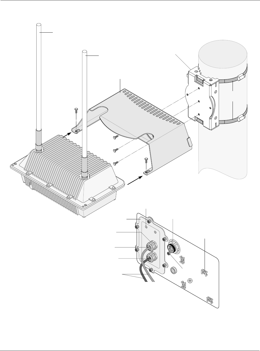
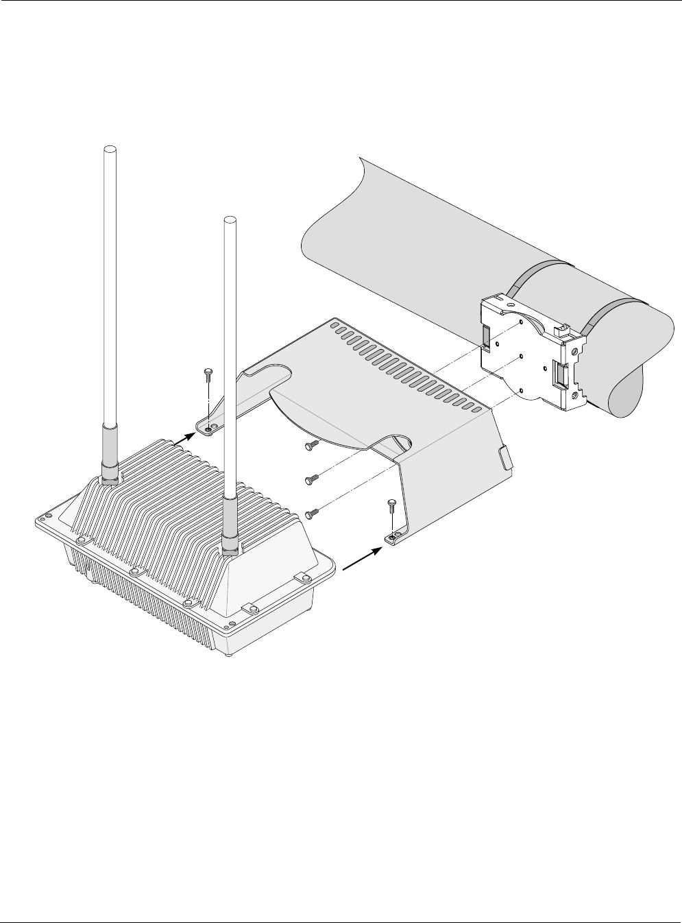
An exploded view of the Tropos 5210 Wi-Fi cell assembly is shown in the next figure.
Note
Antenna(s) must be installed by a trained professional. Operating the unit with non-qualified
antennas is a violation of U.S. FCC Rules Part 15.203(c), Code of Federal Regulations, Title
47. See Appendix C, “Approved Antenna Configurations,” for a listing of antenna options.
Warning
It is illegal to modify the construction of this product. Modifying the operating frequency or
enhancing the transmit output power through the use of external amplifiers or other
equipment is specifically disallowed by the Taiwan DGT “Telecommunications Act.”
Warning
This device is for outdoor or indoor use with conditions that no harmful interference to
authorized radio stations results from the operation of this device. This device shall not
influence aircraft security and/or interfere with legal communications as defined in the
Taiwan DGT “Telecommunications Act.” If this device is found to cause interference, the
operator of this equipment shall cease operating this device immediately until no
interference is achieved.
Preparing for Installation
Tropos 5210 Wi-Fi Cell Installation Guide 3
Figure 1 Tropos 5210 Wi-Fi Cell Exploded View
trp_093
10/100 BaseT
LAN cable
#10-32
hex head 5/16"
machine screws
x5
AC input
power connector
Pole bracket
10/100 BaseT
Management cable
Shielded outdoor
cat5 cable
Cable gland
Aux
Tx/Rx antenna
Tropos 5210 Wi-Fi Cell
Sun shield
Main
Tx/Rx antenna
Hose
clamps
Ground
bolt
LED
Bulkhead
plate
Bottom view of
Tropos 5210 Wi-Fi Cell
Quick tie
anchors

Preparing for Installation
Tropos 5210 Wi-Fi Cell Installation Guide 4
Installation Hardware and Tools
Tropos Networks provides the following accessories to install the Tropos 5210 Wi-Fi cell:
One pole bracket
One sun shield
Two 4-inch diameter hose clamps
Four 6-inch diameter hose clamps
Five 5/16-inch #10-32 stainless steel hex head machine screws
You must supply the following tools:
5/16-inch nut driver
1/4-inch flat blade screwdriver
Tower mounting only: supply stainless or galvanized steel channel stock and 1/2-inch or
5/8-inch nuts, bolts, and washers to connect to the tower arm.
Wood pole mounting only: two 5/8-inch diameter, 3-inch long lag bolts
Site Planning
To ensure safe and durable wiring, installation of the Tropos 5210 Wi-Fi cell must follow
appropriate electrical and building codes. Follow the National Electrical Code (NEC)
requirements, unless local codes in your area take precedence over the NEC code.
The following distance limits apply to installations that have 10/100 Base-T Category 5 network
cables attached to the Tropos 5210 Wi-Fi cell:
300 feet between devices for 100BaseT operation
1300 feet for 10BaseT operation.
The Ethernet duplex and speed setting is configurable.
Note
National Electrical Codes (NEC) Article 800 requires the use of Agency Listed (UL/CSA/
TUV) Building Entrance Protector for all power and data communications cables entering a
building. The NEC intends by Article 800 to protect the building and occupants from fires
caused by transient voltage and current surges.
Note
Ethernet data cable installations having lengths greater than 140 feet in the outdoor
environment must use a UL497 approved (UL/CSA/TUV Listed) primary protection device at
the building entrance. Ethernet data cable installations having lengths less than 140 feet in
the outdoor environment may use a UL497A (UL/CSA/TUV Listed) secondary protection
device at the building entrance. Tropos Data Protection Device and Network Protection
Units are UL497A secondary protection devices.

Preparing for Installation
Tropos 5210 Wi-Fi Cell Installation Guide 5
Location Guidelines
The Tropos 5210 Wi-Fi cell is a radio device and therefore susceptible to interference that can
reduce throughput and range. Follow these guidelines to ensure the best performance:
Install the unit in an area where trees, buildings, and large steel structures do not obstruct
radio signals to and from the antenna. Direct line-of-sight operation is best.
Install the unit away from microwave ovens or other devices operating in the 2.4 GHz
frequency range.
Install the units away from other possible sources of 2.4 GHz WLAN interference, such as
cordless phones, home spy cameras, frequency hopping (FHSS) and DSSS LAN
transceivers (non-802.11b), electronic news gathering video links, radars, amateur radios,
land mobile radio services, local government sites (such as law enforcement), fixed
microwave services, local TV transmission and private fixed point transmitters.
Antenna Options
You can purchase the Tropos 5210 Wi-Fi cell with an integrated omni-directional antenna, or
use an approved external antenna. Omni-directional antennas are best for systems requiring a
signal distribution in more than one direction. To comply with regulatory RF exposure limits,
locate antennas a minimum distance of 7.9 inches (20cm) from people. For antenna model
numbers, refer to Appendix B, “Product Specifications.”
Note
Antenna(s) must be installed by a trained professional. Operating the unit with non-qualified
antennas is a violation of U.S. FCC Rules Part 15.203(c), Code of Federal Regulations, Title
47. See Appendix C, “Approved Antenna Configurations,” for a listing of antenna options.
Warning
It is illegal to modify the construction of this product. Modifying the operating frequency or
enhancing the transmit output power through the use of external amplifiers or other
equipment is specifically disallowed by the Taiwan DGT “Telecommunications Act.”
Warning
This device is for outdoor or indoor use with conditions that no harmful interference to
authorized radio stations results from the operation of this device. This device shall not
influence aircraft security and/or interfere with legal communications as defined in the
Taiwan DGT “Telecommunications Act.” If this device is found to cause interference, the
operator of this equipment shall cease operating this device immediately until no
interference is achieved.

Preparing for Installation
Tropos 5210 Wi-Fi Cell Installation Guide 6
Site Surveys
Due to variations in component configuration, placement, and physical environment, each
installation is unique. Before installing the Tropos 5210 Wi-Fi cell, perform a site survey to
determine the optimum placement of units for maximum range, coverage, and network
performance. Consider the following factors when performing a site survey:
Data rates—Sensitivity and range are inversely proportional to data bit rates. The maximum
radio range is achieved at the lowest workable data rate. A decrease in receiver threshold
sensitivity occurs as radio data rate increases.
Antenna type and placement—Proper antenna configuration is a critical factor in
maximizing radio range. As a general rule, range increases in proportion to antenna height
and gain.
Physical environment—Clear or open areas provide better radio range than closed or filled
areas. The less cluttered the operating environment, the greater the range.
Obstructions—A physical obstruction, such as a building or tree, can block or hinder
communication. Avoid locating antennas in a location where there is an obstruction between
sending and receiving devices.
Building materials—Radio penetration is influenced by the building material used in
construction. For example, drywall construction permits greater range than concrete blocks.
Diversity—The Tropos 5210 Wi-Fi cell supports transmit and receive diversity, which
requires two antennas.

Preparing for Installation
Tropos 5210 Wi-Fi Cell Installation Guide 7
Power Source
The Tropos 5210 Wi-Fi cell supports two options for connecting to a power source:
AC power source (3-wire service) — 3W(P+N+PE) or 3W(2P+PE); 90-480 VAC, 50/60 Hz
NEMA plug, for streetlight photoelectric control power tap (2-wire service) —2W(2P) or
2W(P+N); 90-480 VAC 50/60 Hz
Warning
Connect the AC powered outdoor system only to 90-480 VAC power sources. Do not
connect it to a power source of higher voltage.
Caution
You must install an external grounding wire if the Tropos 5210 Wi-Fi cell is installed on
a non-metal pole or if the metal installation structure is not properly grounded. You
must also ground the outdoor data protection device to a bonded pipe or ground rod.
Make sure that grounding is complete before you connect power to the Tropos 5210
Wi-Fi cell.
Safety
Installing the Tropos 5210 Wi-Fi cell can pose a serious hazard. Be sure to take precautions to
avoid the following:
Exposure to high voltage lines during installation
Falls when working at heights or with ladders
Injuries from dropping tools and equipment
Contact with AC wiring
Mounting Strategies
Tropos 5210 Wi-Fi Cell Installation Guide 8
Mounting Strategies
When choosing mounting locations, consider the available mounting structures and antenna
clearance. The Tropos 5210 Wi-Fi cell should always be mounted with the top of the cell
horizontal and level and with the antennas facing upward.
It is usually best to attach ground and data cables to the cell prior to mounting. Before mounting
the cell, review the wiring instructions in “Grounding the Tropos 5210 Wi-Fi cell” on page 22
and “Connecting a Data Port” on page 30 to determine the best strategy for the selected location.
Note
Since the mounting structure itself is a potential obstruction, the cell should be mounted with
at least 4 feet of clearance between the antennas and the mounting structure.
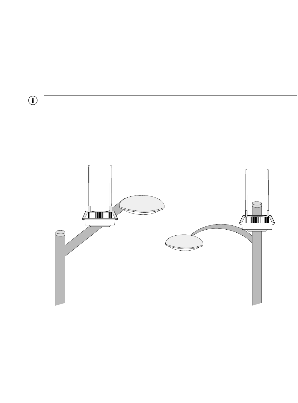
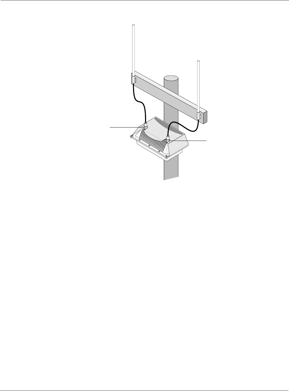
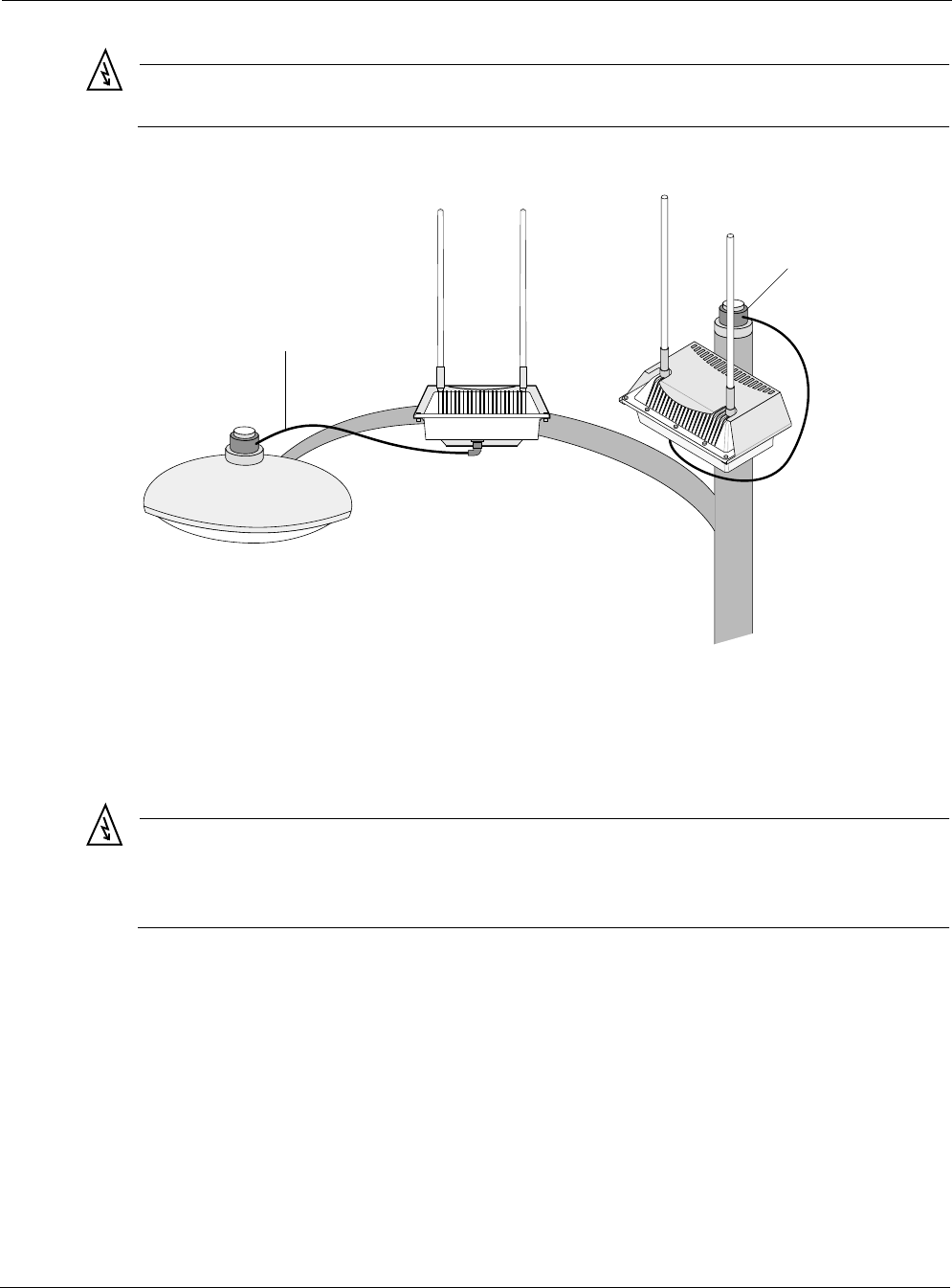
Acceptable options for mounting on a streetlight are shown in Figure 2. In each case the cell is
mounted to assure clearance for the antennas above the height of the streetlight.
Figure 2 Example Mounting Location - Antennas Facing Upward
trp_094
Antennas clear of obstruction
Antennas clear
of obstruction
Proper Use of Hose Clamps
Tropos 5210 Wi-Fi Cell Installation Guide 9
Proper Use of Hose Clamps
The mounting assembly for the Tropos 5210 Wi-Fi cell contains hose clamps to secure the cell
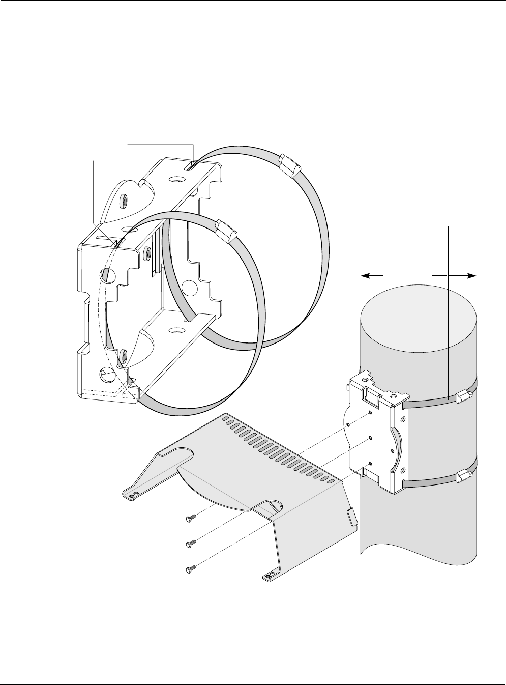
to the mounting structure. Figure 3 illustrates the proper use of the hose clamps when mounting
on large poles (≥ 8 inches). The clamps are routed through holes in the pole bracket as shown in
the figure, and then attached to the pole and tightened.
Figure 3 Proper Use of Hose Clamps - Large Poles (>= 8 Inches)
tr
p
_095
Band goes
through slots
Hose clamp
or steel banding
placement
for larger poles
Sun shield
>= 8 inches
Proper Use of Hose Clamps
Tropos 5210 Wi-Fi Cell Installation Guide 10
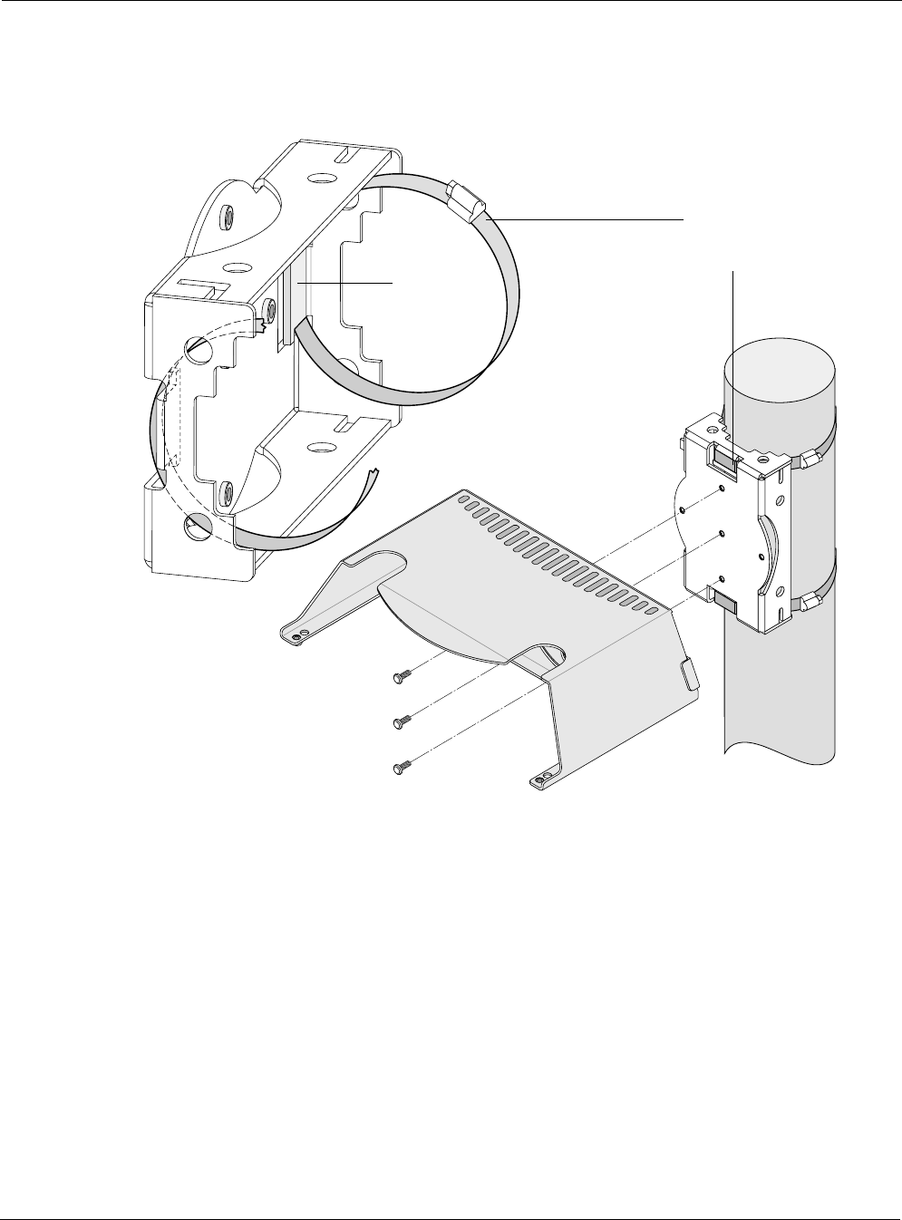
The proper use of the hose clamps for small poles (< 8 inches) is shown in Figure 4. The clamps
are routed behind the inner tabs in the pole bracket, and then attached to the pole and tightened.
Figure 4 Proper Use of Hose Clamps - Small Poles (< 8 Inches)
trp_096
Hose clamp
placement
for smaller poles
Band goes
behind
inner tabs
Sun shield

Mounting Instructions
Tropos 5210 Wi-Fi Cell Installation Guide 11
Mounting Instructions
This section explains how to mount the Tropos 5210 Wi-Fi cell on a pole, tower, or streetlight. It
is best to mount the Tropos 5210 Wi-Fi cell to aluminum or galvanized steel structures. The
mounting brackets are designed to pierce any oxidation layers that are on the outside of the pole,
thereby assuring good quality connection to the grounded structure.
Note
The Tropos 5210 Wi-Fi cell should always be mounted with the top of the cell horizontal and
level and with the antennas facing upward.
Note
It is best to attach ground and data cables to the cell before sliding the cell into the mounted
sun shield, as explained in this section. Before mounting the cell, review the wiring
instructions in “Grounding the Tropos 5210 Wi-Fi cell” on page 22 and “Connecting a Data
Port” on page 30 to determine the best strategy for the selected location.
Note
Mounting to wood, concrete, or painted poles may require primary grounding for the unit.
Check the national electrical codes in your area for specific rules.
Mounting Instructions
Tropos 5210 Wi-Fi Cell Installation Guide 12
Metal Pole Mounting
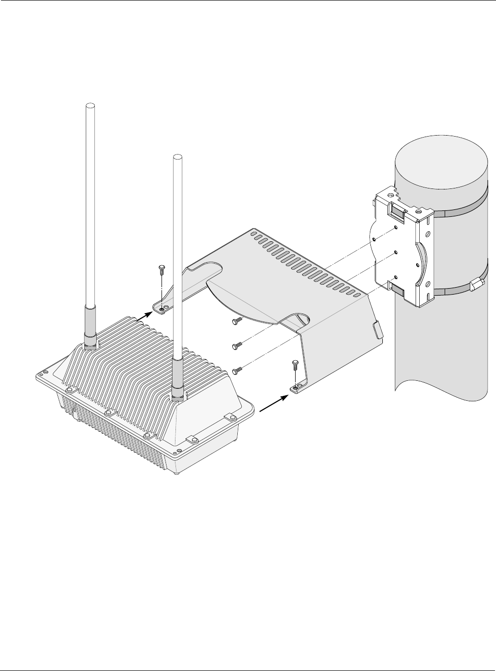
Figure 5 illustrates the proper method of mounting the Tropos 5210 Wi-Fi cell on an outdoor
metal pole.
Figure 5 Metal Pole Mounting
Mount the Tropos 5210 Wi-Fi cell on a metal pole:
1. Select a mounting location. You can attach the Tropos 5210 Wi-Fi cell to any pipe or pole
with diameter between 1.7 inches and 10 inches.
2. Slip the flat portion of the hose clamps under the inside lips of the pole bracket.
3. Use the hose clamps to attach the pole bracket to the pole. Depending upon the diameter of
the pole, you may need to use a single small clamp, single large clamp, or pair of large
clamps joined together.
trp_097
Pole bracket
(rotated)
Tropos 5210 Wi-Fi Cell
Sun shield
Mounting Instructions
Tropos 5210 Wi-Fi Cell Installation Guide 13
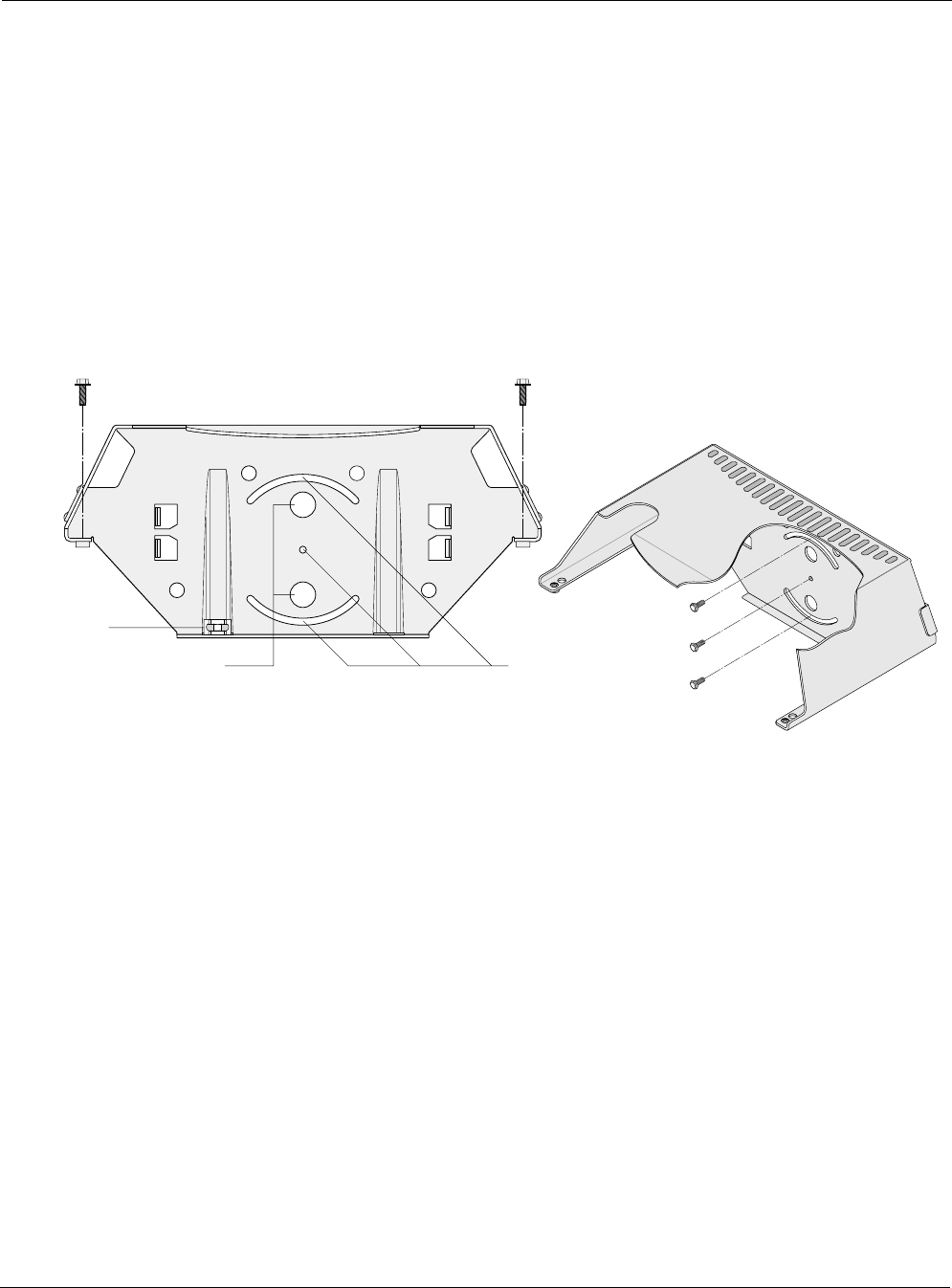
4. Attach the sun shield of the cell to the pole bracket with three 5/16-inch machine screws.
Insert one screw through the hole in the center back of the sun shield and the other two
screws through the curved slot tracks. Figure 6 shows the proper screw locations on the back
of the sun shield.
5. Level the sun shield by rotating the unit along the curved slot tracks. A built-in level is
located on the left side of the shield. Tighten the screws.
6. Slide the Tropos 5210 Wi-Fi cell into place with the antennas on top and secure it at the end
with two #10-32 hex head machine screws.
To continue installing the outdoor system, see “Connecting Cable Attached Antennas” on page
17.
Figure 6 Sun Shield Connections
trp_115
Bubble
level
Use lag bolts
to attach sun shield
to wooden pole
Screws to attach 5210 cell to sun shield
Use machine screws
to attach sun shield
to pole bracket
Mounting Instructions
Tropos 5210 Wi-Fi Cell Installation Guide 14
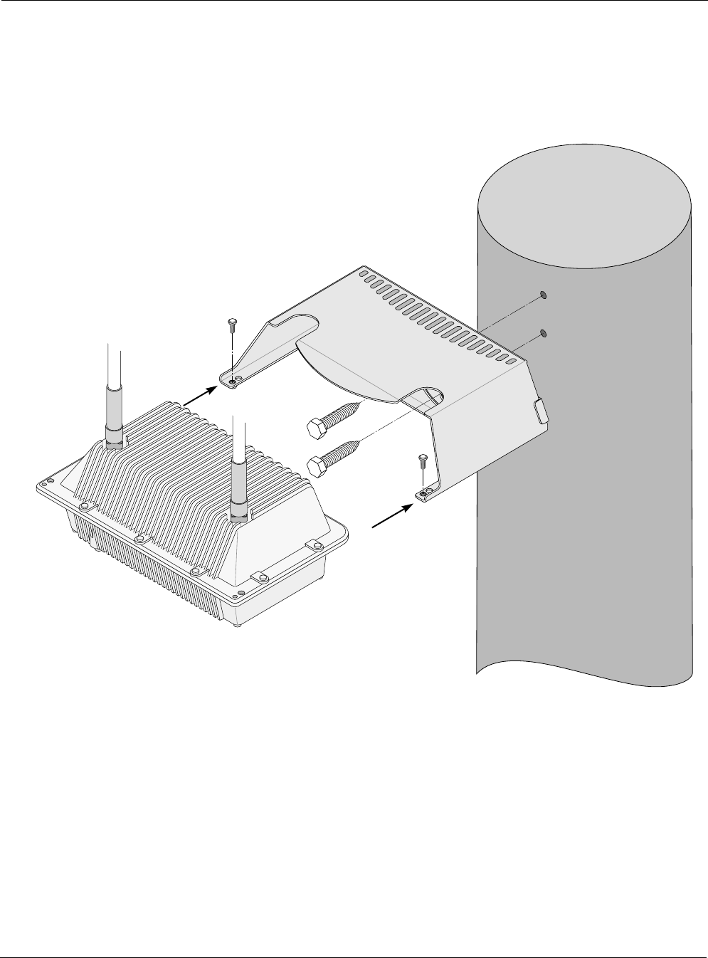
Wood Pole Mounting
Figure 7 shows a typical installation with the Tropos 5210 Wi-Fi cell mounted on an outdoor
wood pole.
Figure 7 Wood Pole Mounting
Mount the Tropos 5210 Wi-Fi cell on a wood pole:
1. Select a mounting location. You can attach the Tropos 5210 Wi-Fi cell to any outdoor wood
pole of diameter at least 1.75 inches.
2. Attach the sun shield of the cell to the pole with two 5/8-inch bolts, making sure that the
shield is level. Figure 6 on page 13 shows the proper bolt locations on the back of the sun
shield.
3. Slide the Tropos 5210 Wi-Fi cell into place and secure it at the end with two #10-32 hex
head machine screws.
trp 098
Tropos 5210 Wi-Fi Cell
Sun shield
Mounting Instructions
Tropos 5210 Wi-Fi Cell Installation Guide 15
To continue installing the outdoor system, see “Connecting Cable Attached Antennas” on page
17.
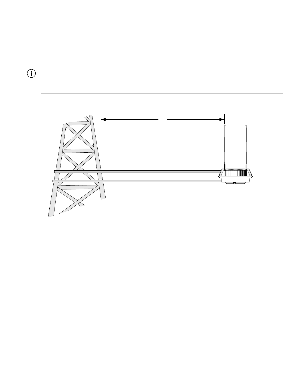
Tower Mounting
You can mount the outdoor system to an outdoor tower.
Note
At the antenna level, the Tropos 5210 Wi-Fi cell must be free from metal obstruction within a
4-foot radius (Figure 8).
Figure 8 Tower Mounting
Mount the Tropos 5210 Wi-Fi cell on a tower:
1. Remove the pole bracket from the sun shield.
2. Make a tower bracket by attaching the sun shield directly to any stainless steel or galvanized
steel channel stock.
3. Attach the sun shield to the tower arm so that the top of the shield is horizontal and level.
4. Tighten the mounting bolts.
5. Slide the Tropos 5210 Wi-Fi cell into place and secure it at the end with two #10-32 hex
head machine screws.
To continue installing the outdoor system, see “Connecting Cable Attached Antennas” on page
17.
trp_099
4'
Brackets not included
Channel stock
Streetlight Mounting
Tropos 5210 Wi-Fi Cell Installation Guide 16
Streetlight Mounting
The Tropos 5210 Wi-Fi cell can be mounted on the horizontal or angled arm of a streetlight.
Figure 9 shows a typical streetlight mounting installation.
Figure 9 Streetlight Mounting
Mount the Tropos 5210 Wi-Fi cell on a streetlight:
1. Select a mounting location. You can attach the Tropos 5210 Wi-Fi cell to any streetlight arm
with diameter 1.75” to 10”.
2. Slip the flat portion of the hose clamp under the inside lip of the pole bracket.
3. Use the hose clamps to attach the pole bracket to the streetlight. Depending upon the
diameter of the pole, you may need to use 2 small clamps, 2 large clamps, or 2 pairs of large
clamps joined together.
trp_100
Pole bracket
Tropos 5210 Wi-Fi Cell
Sun shield

Connecting Cable Attached Antennas
Tropos 5210 Wi-Fi Cell Installation Guide 17
4. Attach the sun shield of the cell to the structure with three 5/16-inch machine screws. Insert
one screw through the hole in the center back of the sun shield and the other two screws
through the curved slot tracks.
5. Level the sun shield by rotating the unit along the curved slot tracks. A built-in level is
located on the left side of the shield. Tighten the screws.
6. Slide the Tropos 5210 Wi-Fi cell into place and secure it at the end with two #10-32 hex
head machine screws.
To continue installing the outdoor system, see “Connecting Cable Attached Antennas” on page
17.
Connecting Cable Attached Antennas
This section applies to external antennas used with Tropos 5210 Wi-Fi cell. You can mount the
antenna on a structure and then use cables to attach it to the cell. After mounting, secure the
antennas with ThreadLocker Loctite 242 and waterproof them using self-fusing EPR tape. (See
Appendix D, “Installation Accessories” for part number.) Figure 10 shows an installation with
external antenna cabling. The unit-attached antennas are sealed at the factory and must be
resealed if they are removed.
Warning
Do not locate the antenna near overhead power lines or other electric light or power circuits,
or where it can come into contact with such circuits. When installing the antenna, take
extreme care not to come into contact with such circuits, as they can cause serious injury or
death. For proper installation and grounding of the antenna, please refer to national and
local codes (e.g. U.S.:NFPA 70, National Electrical Code, Article 810, in Canada: Canadian
Electrical Code, Section 54).
Connecting Cable Attached Antennas
Tropos 5210 Wi-Fi Cell Installation Guide 18
Figure 10 Connecting External Antennas
tr
p
_101
Cables
from antennas
to unit
Aux
Tx/Rx antenna
Main
Tx/Rx antenna
Connecting Cable Attached Antennas
Tropos 5210 Wi-Fi Cell Installation Guide 19
Connect antenna cables:
1. Mount the antennas in a suitable location, following the instructions supplied with the
antennas.
2. Perform a trial installation of the antenna cables.
3. When you are satisfied with the trial placement of the antenna cables, remove the antenna
connections from the Tropos 5210 Wi-Fi cell and apply two drops of ThreadLocker Loctite
242 to the antenna connector thread (Figure 11 on page 20).
4. Install the antenna cables. Be sure to provide a drip loop to divert water away from the
connector.
Note
To ensure good electrical contact with the antenna, do not get Loctite on the center
conductor pin of the antenna cable or outdoor system connector.
Note
Antenna(s) must be installed by a trained professional. Operating the unit with non-qualified
antennas is a violation of U.S. FCC Rules Part 15.203(c), Code of Federal Regulations, Title
47. See Appendix C, “Approved Antenna Configurations,” for a listing of antenna options.
Warning
It is illegal to modify the construction of this product. Modifying the operating frequency or
enhancing the transmit output power through the use of external amplifiers or other
equipment is specifically disallowed by the Taiwan DGT “Telecommunications Act.”
Warning
This device is for outdoor or indoor use with conditions that no harmful interference to
authorized radio stations results from the operation of this device. This device shall not
influence aircraft security and/or interfere with legal communications as defined in the
Taiwan DGT “Telecommunications Act.” If this device is found to cause interference, the
operator of this equipment shall cease operating this device immediately until no
interference is achieved.
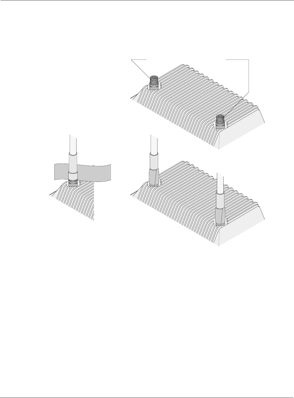
Waterproofing Antenna Connections
Figure 11 illustrates how to waterproof the antenna connections after they are installed.
Waterproof the antenna connections:
1. Locate the self-fusing EPR waterproofing tape included in the antenna installation kit.
2. Separate the liner from the tape.
Connecting Cable Attached Antennas
Tropos 5210 Wi-Fi Cell Installation Guide 20
3. Pre-stretch the tape and wrap it tightly around the connector.
If you installed the antennas using antenna cables, be sure to waterproof those connections as
well.
Figure 11 Waterproofing Antenna Connections
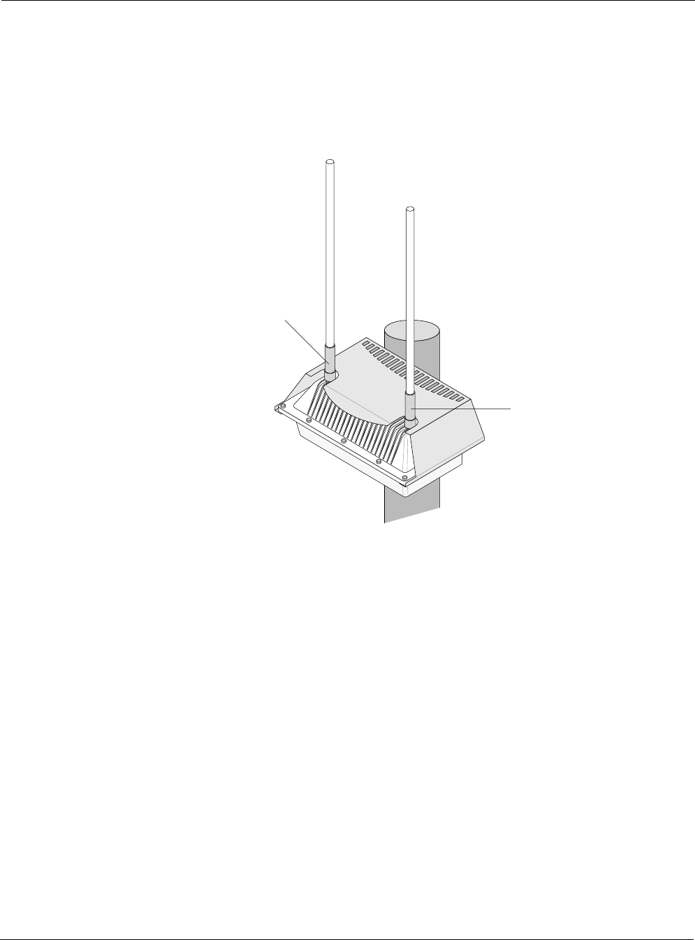
Installing Customer-Provided Antennas
Figure 12 shows the location of the antennas installed with the Tropos 5210 Wi-Fi cell. The
following steps explain how to install replace customer-provided antennas; factory-installed
antennas should not be removed.
Replace the Tropos 5210 Wi-Fi cell antennas:
1. Turn power off to the Tropos 5210 Wi-Fi cell.
2. Remove the self-fusing EPR waterproofing tape from the antenna connections.
3. Unscrew the antennas.
4. Replace the antennas.
Apply 2 drops of Loctite to threads
trp_102
Apply tape around
antenna joints
Connecting Cable Attached Antennas
Tropos 5210 Wi-Fi Cell Installation Guide 21
5. Apply two drops of Loctite Threadlocker 242 to the antenna connector thread.
6. Locate the self-fusing EPR waterproofing tape included in the antenna installation kit.
7. Separate the liner from the tape.
8. Pre-stretch the tape and wrap it tightly around the connector.
Figure 12 Replacing Tropos 5210 Wi-Fi cell Antennas
trp_103
Aux
Tx/Rx antenna
Main
Tx/Rx antenna
Grounding the Tropos 5210 Wi-Fi cell
Tropos 5210 Wi-Fi Cell Installation Guide 22
Grounding the Tropos 5210 Wi-Fi cell
Caution
You must install an external grounding wire if the Tropos 5210 Wi-Fi cell is installed on
a non-metal pole or if the metal installation structure is not properly grounded. You
must also ground the outdoor data protection device to a bonded pipe or ground rod.
Make sure that grounding is complete before you connect power to the Tropos 5210
Wi-Fi cell.
The grounding arrangement for the Tropos 5210 Wi-Fi cell is shown in Figure 13.
Figure 13 Ground Arrangement
Ground the Tropos 5210 Wi-Fi cell:
1. Insert the grounding screw into the grounding screw hole on the bottom of the cell.
2. Connect a length of #10 AWG bare copper wire to the grounding screw and tighten.
3. Connect the other end of the grounding wire to a grounding strap that is attached to a
grounded surface or other earth ground such as a grounding rod.
4. Secure the #10 AWG bare copper wire into the split-bolt connectors by first tightening the
nuts finger tight and then tightening further by applying a 1/4 turn with an open-end wrench.
ground stud and ground nut should be tightened to a torque of 20 ft-lbs.
trp_104
10 AWG wire
to ground
Grounding strap
on pipe or grounding rod
Grounding the Tropos 5210 Wi-Fi cell
Tropos 5210 Wi-Fi Cell Installation Guide 23
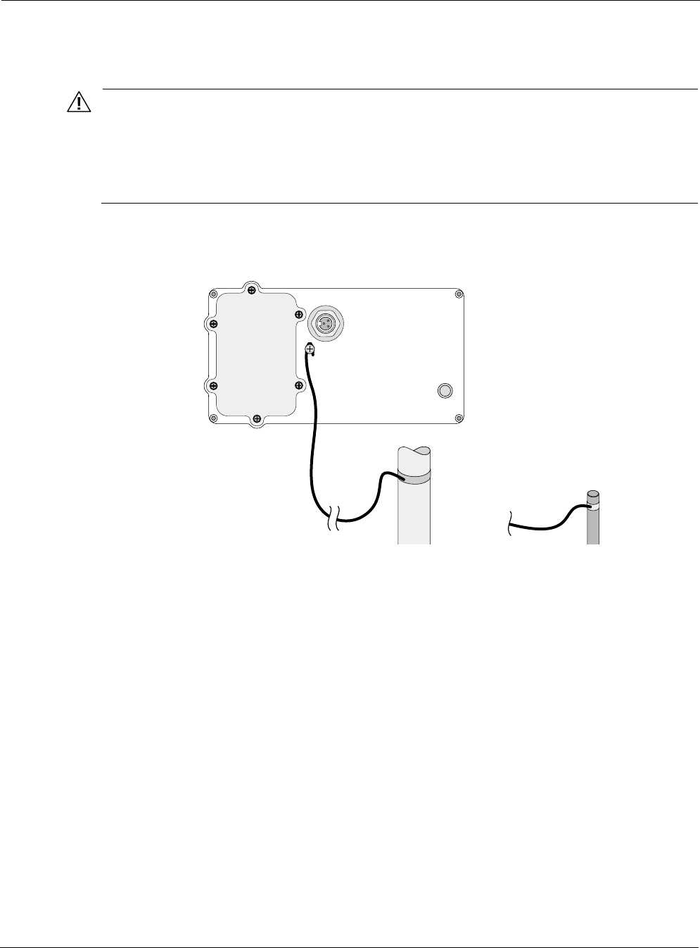
Grounding the Data Protection Device
The grounding arrangement for an indoor data protection device is shown in Figure 14.
Ground an indoor data protection device:
1. Place the protection device as close to the building entrance as possible.
2. Connect a length of #10 AWG bare copper wire to the ground post on the data protection
device.
3. Connect the other end of the grounding wire to the ground connection of an electrical outlet
or a grounded water pipe.
Figure 14 Grounding the Indoor Network Protection Unit
trp_069
10 AWG wire
to ground
Grounding wire
to elecrtical outlet ground
or water pipe
RJ 45
port
Indoor network
protection unit
Data cable enters
building wall
through conduit
To network

Connecting Power
Tropos 5210 Wi-Fi Cell Installation Guide 24
Connecting Power
This section explains the different categories of electrical power and provides procedures for
connecting the outdoor system to power. There are two options for connecting the Tropos 5210
Wi-Fi cell to a power source:
AC power source (3-wire service) — 3W(P+N+PE) or 3W(2P+PE); 90-480 VAC, 50/60 Hz
NEMA plug, for streetlight photoelectric control power tap (2-wire service) —2W(2P) or
2W(P+N); 90-480 VAC 50/60 Hz
Warning
Before you work on an electrical circuit, make sure the power is off. Turn off the breaker to
the circuit you plan to work on. Post a sign on the service panel so nobody tries to reconnect
power while you are working on the circuits. Double-check the circuit with a circuit tester
before you touch it to make sure the correct breaker has been disconnected.
Caution
You must install an external grounding wire if the Tropos 5210 Wi-Fi cell is installed on
a non-metal pole or if the metal installation structure is not properly grounded. You
must also ground the outdoor data protection device to a bonded pipe or ground rod.
Make sure that grounding is complete before you connect power to the Tropos 5210
Wi-Fi cell.
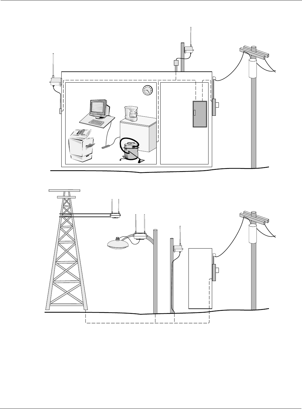
Categories of Power
The IEEE/ANSI C62.41 standards (equivalent to the IEC Category IV standards) define
Categories A-C. Equipment designed to a CAT C standard is resistant to much higher energy
transients than one designed to CAT B or CAT A standards. Within a category, a higher voltage
rating denotes a higher transient withstand rating.
Table 1 lists power types and Figure 15 shows hook-ups for the different power categories.
Table 1 IEEE/ANSI C62.41 Power Categories
Category Summary Examples
CAT C Outside and service
entrance
•Service drop from pole to building entrance
•Run between meter and distribution panel
•Overhead line to detached buildings
•Underground lines to well pumps

Connecting Power
Tropos 5210 Wi-Fi Cell Installation Guide 25
CAT B Major feeders and
short branch circuits
•Distribution panel devices
•Bus and feeder systems in industrial plants
•Heavy appliance outlets with “short” connections to the
service entrance
•Lightning systems in commercial buildings
CAT A Outlets and long
branch circuits
•All outlets at more than 10 m (30 ft) from Category B with
wires #14-10
•All outlets at more than 20 m (60 ft) from Category C with
wires #14-10
Table 1 IEEE/ANSI C62.41 Power Categories
Category Summary Examples
Connecting Power
Tropos 5210 Wi-Fi Cell Installation Guide 26
Figure 15 IEEE/ANSI C62.41 Power Categories
trp_105
Category A Category B
Outdoor units powered from
distribution panel are in
Overvoltage Installation Category B
Category C
Outdoor units powered from electrical meter are in
Overvoltage Installation Category C
Category C
Connecting Power
Tropos 5210 Wi-Fi Cell Installation Guide 27
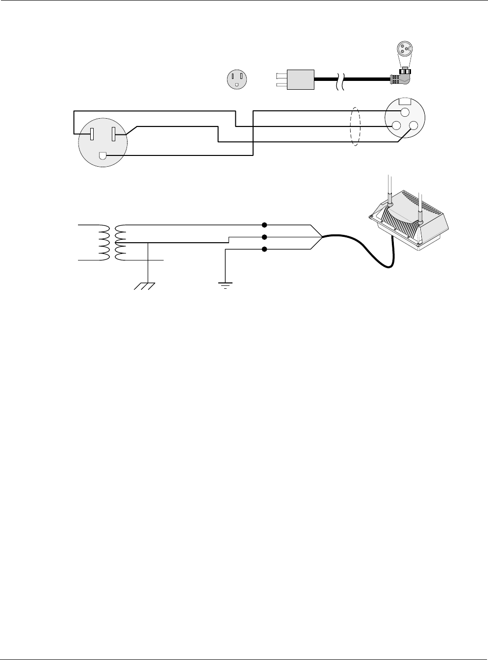
Connecting to AC Power (Category C)
The AC power connections for a Category C AC power source are shown in Figure 16.
Figure 16 Connecting Category C AC Power
Connect an AC power source:
1. Verify that the service voltage is 90-480 VAC 50/60 Hz.
2. Verify that power is turned off on the designated circuits.
3. Install 1/2 inch liquid-tight conduit from the building entrance point to within 3 feet of the
outdoor system.
4. Run 3-wire AC service through the conduit.
5. Connect the conduit to a junction box. The conduit and junction box must be IEEE/ANSI
compliant and suitable for outdoor use.
Note
Data and power must never be enclosed in the same conduit.
6. Connect the AC cable to the cell and tighten the nut hand-tight. See Figure 17 on page 28.
7. Connect the Tropos 5210 Wi-Fi cell to a 90-480 VAC 50/60 Hz CAT C power source.
8. Reenergize the circuit and confirm that power to the Tropos 5210 Wi-Fi cell comes on.
trp_106
AC power
from meter
AC wiring in
junction box
To power
source
Green wire
Wire nuts
White wire
Black wire
To outdoor unit
Connecting Power
Tropos 5210 Wi-Fi Cell Installation Guide 28
Note
The Tropos 5210 Wi-Fi cell is equipped with additional AC surge protection and dual fuse
branch circuit protection. Additional ISA branch circuit protection is not required in the
upstream power distribution.
Figure 17 Connecting the AC Power Cable to the Cell
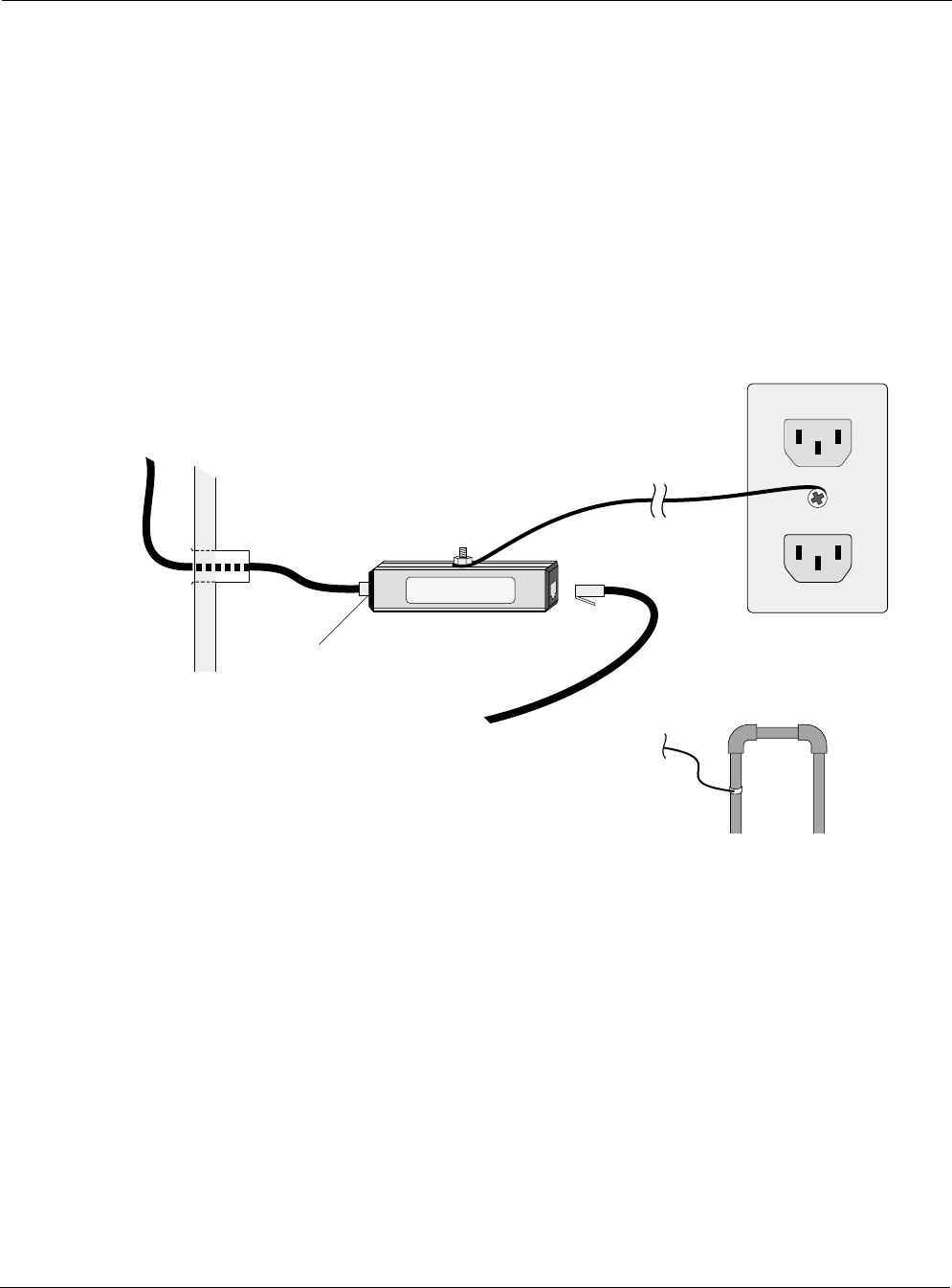
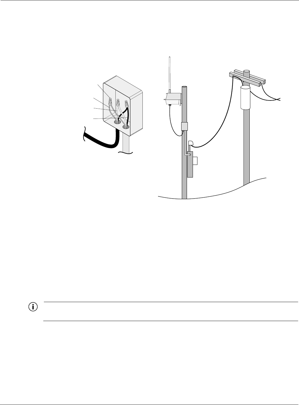
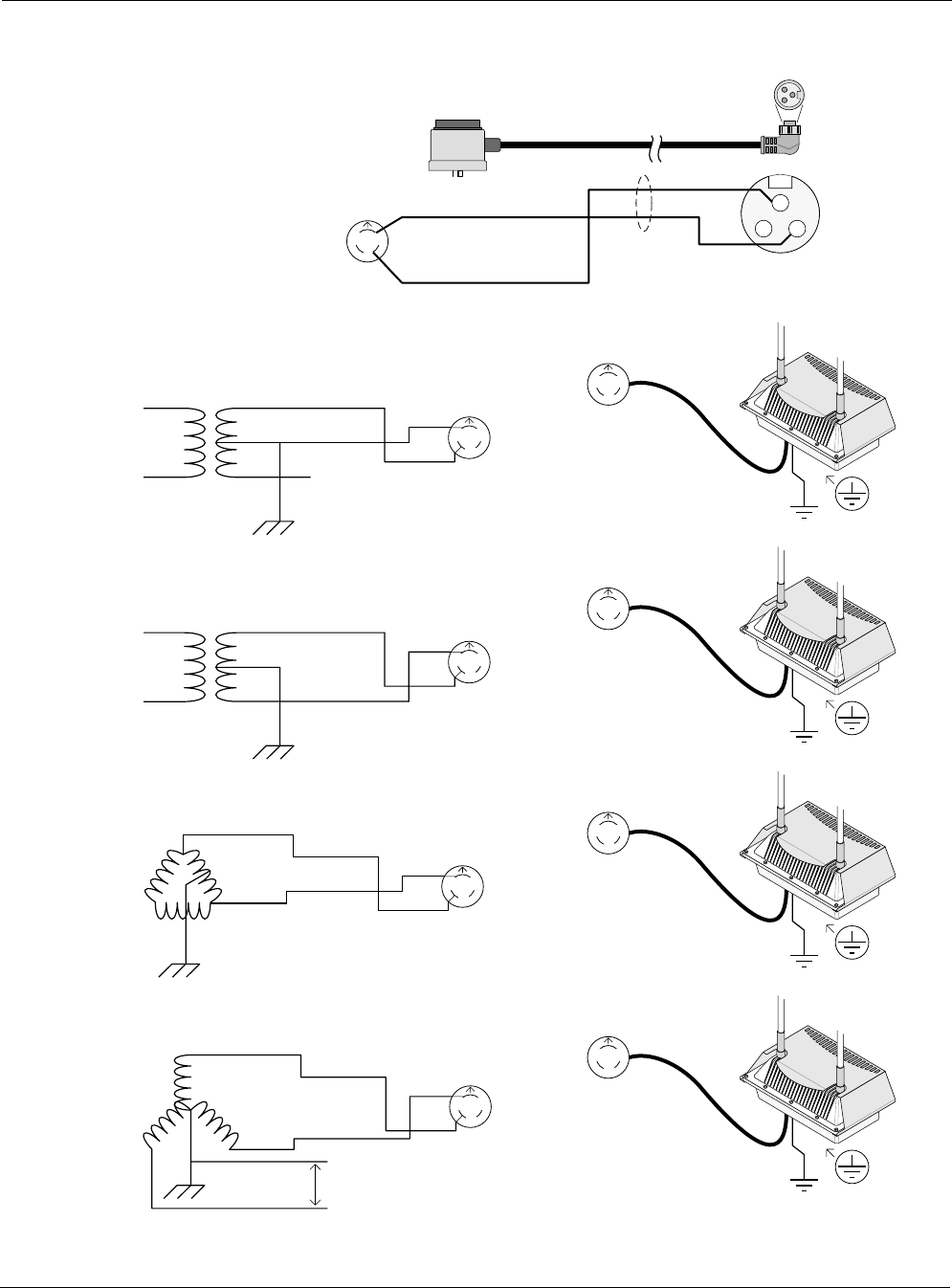
Connecting to Streetlight Power (Category C)
The power connections for Category C streetlight power are shown in Figure 18. Use the 3-
prong NEMA twist-lock adapter with twist-lock style photoelectric controls for outdoor lighting
commonly used by utilities. The NEMA twist-lock adapter can be used only with UL 773 listed
outdoor lighting controls rated for and operated at 90 to 480 VAC 50/60 Hz.
trp_107
Tighten nut to secure
power connection
Connecting Power
Tropos 5210 Wi-Fi Cell Installation Guide 29
Warning
Be extremely careful when connecting to Category C streetlight power.
Figure 18 Connecting Streetlight Power
Warning
Connect the outdoor system only to a twist-lock style outdoor lighting control powered by 90-
480 VAC 50/60 Hz. Do not connect it to twist-lock style outdoor lighting controls powered by
higher voltage.
Connect a streetlight power source:
1. Verify that the service voltage is 90-480 VAC 50/60 Hz.
2. Verify that power is turned off on the designated circuits.
3. Remove the photosensor from the streetlight.
4. Connect the NEMA 3 prong plug from the Tropos 5210 Wi-Fi cell to the photosensor
connector on the street light.
5. Connect the photosensor to the top of the NEMA 3 prong plug.
trp_108
AC power from
power adapter
on photosensor
AC power from
power adapter
on photosensor

Connecting a Data Port
Tropos 5210 Wi-Fi Cell Installation Guide 30
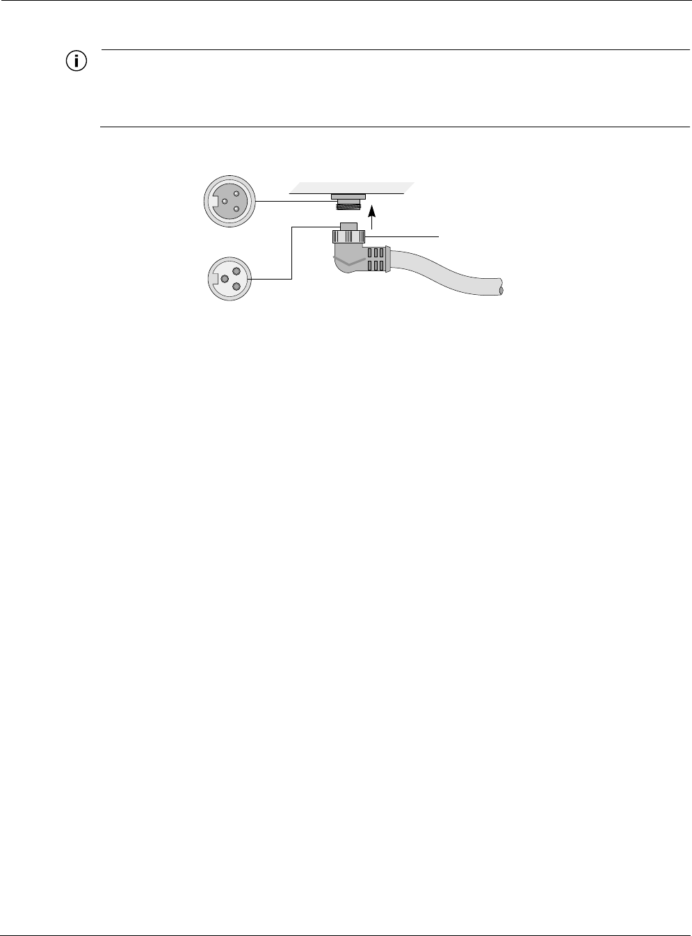
6. Connect the AC plug to the Tropos 5210 Wi-Fi cell and tighten hand-tight.
7. Reenergize the circuit and confirm that power to the Tropos 5210 Wi-Fi cell comes on.
Note
The Tropos 5210 Wi-Fi cell is equipped with additional AC surge protection and dual fuse
branch circuit protection. Additional ISA branch circuit protection is not required in the
upstream power distribution.
Note
Do not leave connectors open to the environment. Connectors should be covered with
closure caps when not in use. Closure caps should be tightened to be snug.
Connecting a Data Port
The Tropos 5210 Wi-Fi cell is equipped with two Ethernet ports that support RJ45 and punch
down block termination options. Use either port for the wired connection to the Tropos 5210
Wi-Fi cell gateway. Use the Management port as the wired configuration interface. Use the
Management or LAN port to attach wired peripherals such as a traffic camera or IP networking
device.
Note
The Tropos 5210 Wi-Fi cell node comes pre-configured. For post-installation changes in
configuration, you can communicate with the node by way of its wireless connection. For
more information, see the Tropos Networks Configuration Guide.
Note
Only use shielded Cat5 cable rated for outdoor use. For protection against risk of fire,
electrical hazard and to ensure the reliable operation of this equipment, the shields of the
Cat5 cable must be properly terminated and bonded to the unit and to the protective earth
(PE) at the building entrance.
Note
National Electrical Codes (NEC) Article 800 requires the use of Agency Listed (UL/CSA)
Building Entrance Protector for all power and communications cables entering a building.
The NEC intends by Article 800 to protect the building and occupants from fires caused by
transient voltage and current surges.

Connecting a Data Port
Tropos 5210 Wi-Fi Cell Installation Guide 31
Warning
DC voltage may be present on RJ-45 pins 4,5 (+) and 7,8 (-)
Note
This is not a mid-span powered device. Never attempt to daisy-chain Power Over Ethernet
devices.
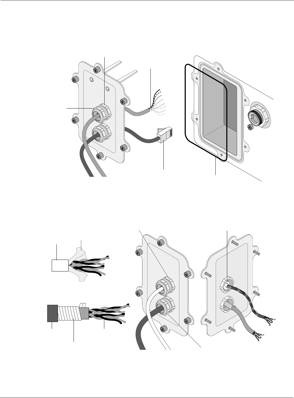
Figure 19 illustrates the options for routing cables for connection to the Tropos 5210 Wi-Fi cell.
You can attached cable with exposed wires to punch down blocks or terminate the cables with an
Connecting a Data Port
Tropos 5210 Wi-Fi Cell Installation Guide 32
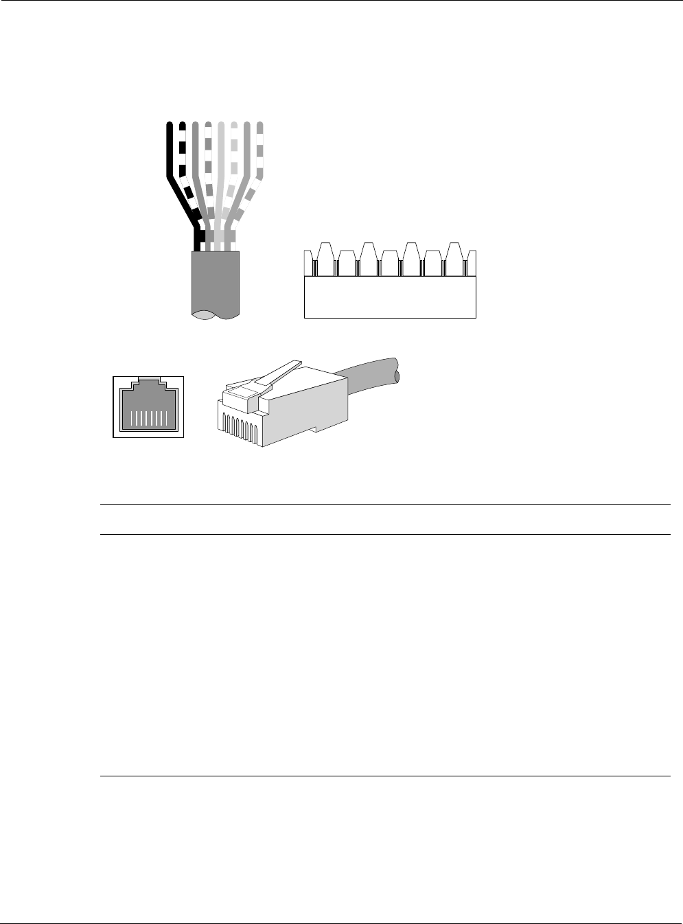
RJ45 jack for port connection. Figure 20 shows the layered shield and jacket for the data cable,
which must be removed to expose the inner cable and twisted pairs.
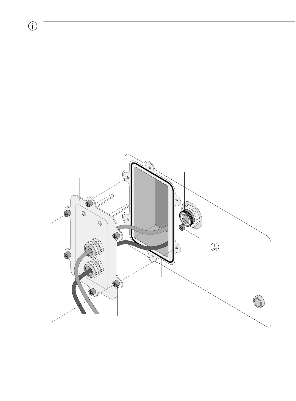
Figure 19 Options for Connecting a Data Port
Figure 20 Data Cable Detail
trp_111
Watertight bulkhead
cable glands
Wires exposed for
punch-down block
Cable terminated with
RJ45 jack for port
connection
O-ring
Shield
termination
trp_117
Watertight bulkhead
cable glands
Cable
Outer
jacket
Twisted
pairs
Securely tighten gland
for weathertight seal
Conductive
shield
Belfoil
shield
Terminate cable shield
at cable gland
Connecting a Data Port
Tropos 5210 Wi-Fi Cell Installation Guide 33
Note
Attach ground and data cables to the cell before sliding the cell into the sun shield.
Connect to the data port
1. Verify that power is turned off on the designated circuits.
2. Run shielded Category 5 Ethernet cable appropriate for outdoor use from a data protection
unit to the Tropos 5210 Wi-Fi cell.
3. Connect one end of the Category 5 cable to the protection unit.
4. Remove the connector access cover on the bottom of the cell.
5. Run raw cables for the Management or LAN port, or both, through the bulk head openings,
allowing sufficient length to terminate the cables without causing crowding in the
connection area. See Figure 21.
Figure 21 Data Port Connection
6. Connect the cable ends that were routed through the connector access cover to the LAN and
Management ports on the cell. Attach the cables directly to the punch down block, or use an
appropriate RJ45 8-pin modular plug to terminate the cables at the desired lengths. The outer
jacket and conductive shield must be stripped to expose the twisted pairs for attachment, as
tr
p
_112
O-ring
AC power
connector
Cable guides
Ground bolt
Bulkhead plate
Tighten six screws to
fasten bulkhead plate
Resetting the Cell
Tropos 5210 Wi-Fi Cell Installation Guide 34
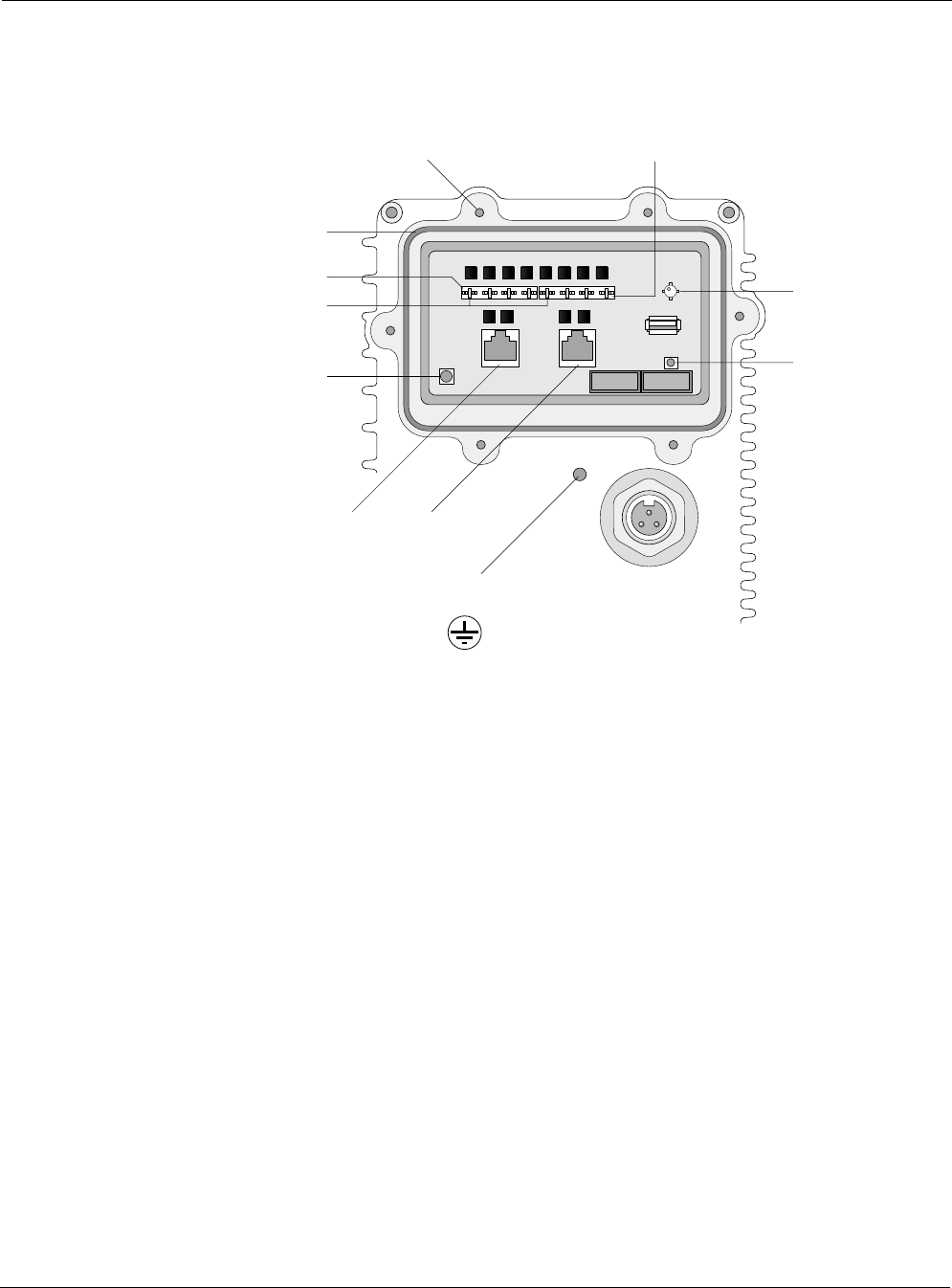
shown in Figure 20. The proper location of the connections on the cell circuit board is shown
in Figure 22.
Figure 22 Circuit Board Connection Locations
7. Verify that the protection unit is properly grounded.
8. Reconnect the circuit and confirm that power to the Tropos 5210 Wi-Fi cell comes on.
9. If you are using external antennas, install the antenna cables. Be sure to provide a drip loop
to divert water away from the connector.
10. Separate the liner from the self-fusing EPR waterproofing tape.
11. Pre-stretch the tape and wrap it tightly around the connector.
Resetting the Cell
You can use the Reset button on the circuit board to reset the hardware and software and to turn
the cell off if it is operating on battery power.
Perform a hardware reset
Press the reset button for one second.
Turn the battery-powered cell off
Press and hold the Reset button for 3-5 seconds.
trp_110
AC power
connector
Management
port
Reset
Brown
Management
punch-down block
LAN punch-down blockScrew holes for bulkhead plate
LED
LED
Threaded hole for
grounding bolt
O-ring gasket
LAN
port

Connecting Peripherals
Tropos 5210 Wi-Fi Cell Installation Guide 35
Connecting Peripherals
The Tropos 5210 Wi-Fi cell can be configured to source DC power on the Ethernet connector
pins 4,5 and 7,8, This capability allows the cell to power remote peripherals such as backhaul
point-to-point radios, video cameras, or fiber optic transceivers. The Tropos PoE power sourcing
capability DC output is a fully isolated supply and may be used to power either positive or
negative polarity peripherals.
The Tropos PoE power sourcing capability is not compliant with the IEEE 802.3af standard;
however, many IEEE 802.3af-compliant power devices (PDs) will operate using the power
sourcing equipment capabilities of the Tropos 5210 Wi-Fi cell.
The Tropos 5210 Wi-Fi cell can supply up to a total of 14W of DC power distributed to the LAN
port, Management port, or both. Each port must be configured for the same voltage. To
configure the voltage, use the Tropos Configuration Utility (see Tropos Networks User Guide)
or an element management system such as Tropos Control EMS (see the Tropos Control EMS
Installation and User Guide). The DC output voltage can be configured to 12Vdc, 24Vdc,
48Vdc, or to the Off state (0Vdc). Table 2 lists the maximum power output as a function of
voltage.
In the event of an over-current or short-circuit fault event, the Tropos 5210 Wi-Fi cell will
remove PoE output for three to five seconds before attempting to resume sourcing power to the
peripheral device.
The power sourcing feature is covered by battery backup (“Battery Backup Operation” on page
38). If the battery backup capability is installed, PoE output power is unaffected by the
temporary loss of AC power.
Table 2 PoE Power Sourcing Power Output
Voltage Max Power Output
12Vdc 14W
24Vdc 12W
48Vdc 10W
Connecting Peripherals
Tropos 5210 Wi-Fi Cell Installation Guide 36
Figure 23 shows the pin locations for the RJ45 connector, and Table 3 shows the associated pin
descriptions.
Figure 23 RJ45 Pin Locations
Table 3 RJ45 Pin Descriptions for Data Connection
Pin T/R Signal Color Description
1 T TXD+ Orange-White TX Data 10/100BaseT
2 R TXD- Orange TX Data 10/100BaseT
3 T RXD+ Green-White RX Data 10/100BaseT
4 R PoE+ Blue Power output, 0, 12, 24, 48 Vdc (+)
5 T PoE+ Blue-White Power output, 0, 12, 24, 48 Vdc (+)
6 R RXD- Green RX Data 10/100BaseT
7 T PoE- Brown-White Power output, 0, 12, 24, 48 Vdc (-)
8 R PoE- Brown Power output, 0, 12, 24, 48 Vdc (-)
trp_109
18765432 7
68
5
4
3
2
1
trp_116
18765432
Category 5
cable
Punch down block
Blue
Orange
Green
Brown
TRTRTRTR

Connecting Peripherals
Tropos 5210 Wi-Fi Cell Installation Guide 37
Note
Only use shielded Cat5 cable rated for outdoor use. For protection against risk of fire,
electrical hazard and to ensure the reliable operation of this equipment, the shields of the
Cat5 cable must be properly terminated and bonded to the unit and to the protective earth
(PE) at the building entrance.
Note
Since peripheral connections require AC power, this configuration is not compatible with
Power over Ethernet.
Battery Backup Operation
Tropos 5210 Wi-Fi Cell Installation Guide 38
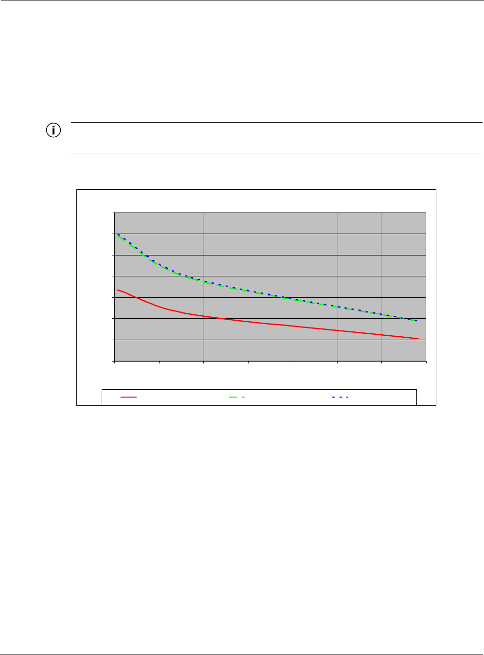
Battery Backup Operation
The Tropos 5210 Wi-Fi cell may contain an automatically recharging battery, which provides an
integrated uninterruptible power supply (UPS). The available backup time depends upon the
level of network traffic serviced by the cell and the ambient temperature. Figure 24 shows the
relationship between average throughput and battery uptime.
Note
The internal battery is not field replaceable.
Figure 24 Average Battery Backup Time
Safety Information for the Tropos 5210 Wi-Fi Cells
The Federal Communications Commission (FCC) with its action in ET Docket 96-8 has adopted
a safety standard for human exposure to RF electromagnetic energy emitted by FCC certified
equipment. The Tropos 5210 products meet the uncontrolled environmental limits found in
OET-65 and ANSI C95.1, 1991. Proper operation of this radio according to the instructions
found in this manual and the hardware and software guides on the Tropos 5210 Wi-Fi cells result
in user exposure that is substantially below the FCC recommended limits.
The following are guidelines to insure safe operation of the Tropos 5210 Wi-Fi cells:
Do not touch or move the antenna(s) while the unit is transmitting or receiving.
Do not hold any component containing a radio such that the antenna is very close to or
touching any exposed parts of the body, especially the face or eyes, while transmitting.
Battery Uptime vs. Average Throughput
0:00
2:00
4:00
6:00
8:00
10:00
12:00
14:00
0 600 1200 1800 2400 3000 3600 4200
Throughput (kb/s)
Battery Uptime (HH:MM)
-20° C ambient 25°C ambient 55°C ambient

Service Instructions
Tropos 5210 Wi-Fi Cell Installation Guide 39
Do not operate the radio or attempt to transmit data unless the antenna is connected;
otherwise, the radio may be damaged.
Use in specific environments:
Do not operate a portable transmitter near unshielded blasting caps or in an explosive
environment unless it is a type especially qualified for such use.
The use of wireless devices in hazardous locations is limited to the constraints posed by
the safety directors of such environments.
The use of wireless devices on airplanes is governed by the Federal Aviation
Administration (FAA).
The use of wireless devices in hospitals is restricted to the limits set forth by each
hospital.
Antenna use:
The Tropos 5210 Wi-Fi cells must only be used with Tropos-approved components and
antennas. See Appendix B, “Product Specifications,” for details.
In order to comply with FCC RF exposure limits, dipole antennas should be located at a
minimum distance of 7.9 inches (20 cm) or more from the body of all persons.
High-gain, wall-mount or mast-mount antennas are designed to be professionally
installed and should be located at a minimum distance of 12 inches (30 cm) or more from
the body of all persons. Please contact your professional installer, VAR, or antenna
manufacturer for proper installation requirements.
Battery backup:
The Tropos 5210 Wi-Fi cell may contain a lithium-ion battery. To avoid the possibility
of an explosion, the Tropos 5210 Wi-Fi cell should not be exposed to any temperatures
higher than 85 degrees C.
Service Instructions
This section contains service information for the Tropos 5210 Wi-Fi cells.
Note
The Tropos 5210 Wi-Fi cells have no user serviceable parts inside. The following
information is intended for trained service personnel only.
Clock Battery
The Tropos 5210 Wi-Fi cells have a real-time clock which is powered by a small lithium
rechargeable battery. If the real-time clock fails, return the unit to Tropos Networks for
servicing.

Service Instructions
Tropos 5210 Wi-Fi Cell Installation Guide 40
Caution
There is a danger of explosion if the battery is incorrectly replaced. Replace the battery
with only the same or equivalent type recommended by the manufacturer. Dispose of
used batteries according to the manufacturer’s instructions.
Caution
There is a risk of explosion if the battery is replaced by an incorrect type.
Caution
Dispose of batteries according to the manufacturer’s instructions.
Tropos 5210 Wi-Fi Cell Installation Guide 41
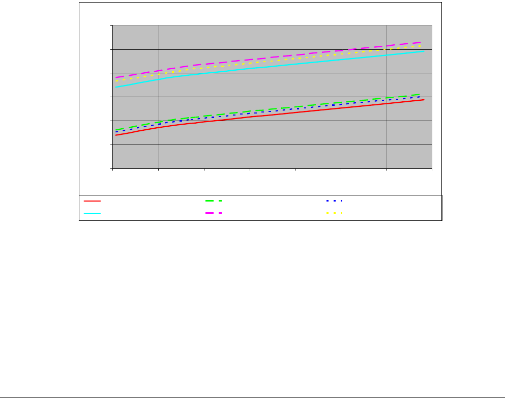
APower Consumption
Several factors influence the power consumption at any given time, including the level of
network traffic, temperature, and whether a powered peripheral device is connected to the LAN
or Management port of the Tropos 5210 Wi-Fi Cell. Temperature influences power consumption
due to the internal freeze protection capability of the Tropos 5210 Wi-Fi Cell.
Figure 25 shows the relationship between throughput and AC power consumption.
Figure 25 AC Power Consumption
Power Consumption vs. Average Throughput
0
10
20
30
40
50
60
0 600 1200 1800 2400 3000 3600 4200
Throughput (kb/s)
Power Consumption (W)
120V AC (rms), 60 Hz, no POE output 208V AC (rms), 60 Hz, no POE output 240V AC (rms), 50 Hz, no POE output
120V AC (rms), 60 Hz, 8.5W POE output 208V AC (rms), 60 Hz, 8.5W POE output 240V AC (rms), 50 Hz, 8.5W POE output

Tropos 5210 Wi-Fi Cell Installation Guide 42
BProduct Specifications
This appendix contains the product specifications for the Tropos 5210 Wi-Fi Cell:
“Physical Specifications” on page 42
“Interfaces” on page 43
“Power Options / Consumption” on page 45
“Power Over Ethernet - Power Sourcing” on page 45
“Certifications, Other” on page 46
Table 4 Physical Specifications
Physical Dimensions Height Width Depth
Inches 5.3 13.2 7.9
Centimeters 13.5 33.5 20.1
Weight
lbs - maximum 14 Includes all brackets
and sun shields
Kg - maximum 6.35
Mounting Pole Diameter 1.75” to 10”
Temperature Min Max
AC Powered Operating Range -40C 55C
Storage Range -45C 85C
Weather Rating UL579/IEC 60529 IP67
Corrosion Resistance MIL-STD-810F 509.4 Salt Fog
Color Gloss white
Shock and Vibration
Operational: ETSI 300-19-2-4
Specification T41.E,
class 4M3
Transportation: ISTA 2A
Random Bounce
Random Vibration
6 Corner Drop Test

Tropos 5210 Wi-Fi Cell Installation Guide 43
Table 5 Interfaces
Data Interface Distance (ft) Connector
IEEE 802.3 10/100BaseT 1300 (10BaseT Duplex Setting)
300 (100BaseT Duplex Setting)
RJ45, type 110 punch
down block
Management Interface Distance (ft) Connector
IEEE 802.3 10/100Base T 1300 (10BaseT Duplex Setting)
300 (100BaseT Duplex Setting)
RJ45, type 110 punch
down block
Wireless Interface
Standard IEEE 802.11b/g Wi-Fi
Frequency Range 2400 to 2485 MHz ISM Band
Modulation DSSS; DBPSK @ 1 Mbps,
DQPSK @ 2 Mbps,
CCK @ 5.5 and 11 Mbps
OFDM @ 54, 48, 36, 24, 18, 12, 6
FCC/RSS210
Models 5210XXX0
Rx Sensitivity -98dBm (1 Mbps)
-96dBm (2 Mbps)
-95dBm (5.5 Mbps)
-91dBm (11 Mbps)
-93dBm (6 Mbps)
-92dBm (9 Mbps)
-90dBm (12 Mbps)
-88dBm (18 Mbps)
-85dBm (24 Mbps)
-82dBm (36 Mbps)
-77dBm (48 Mbps)
-74dBm (54 Mbps)

Tropos 5210 Wi-Fi Cell Installation Guide 44
FCC/RSS210
Models 5210XXX0
Rx Saturation
Maximum Power at Antenna Port
-5dBm (1 Mbps)
-5dBm (2 Mbps)
-5dBm (5.5 Mbps)
-5dBm (11 Mbps)
-5dBm (6 Mbps)
-5dBm (9 Mbps)
-5dBm (12 Mbps)
-10dBm (18 Mbps)
-30dBm (24 Mbps)
-35dBm (36 Mbps)
-35dBm (48 Mbps)
-35dBm (54 Mbps)
Antennas External
Antenna Diversity Transmit/Receive
Impedance 50 ohms
VSWR 1.5 : 1
Connectors (two) N (female)
Indicator - Status Lamp Red/Green
Table 5 Interfaces (continued)

Tropos 5210 Wi-Fi Cell Installation Guide 45
Table 6 Power Options / Consumption
Single Phase VAC
IEEE/ANSI C62.41 CAT C Power Source
IEC Category IV Power Source
90-480 VAC 50/60 Hz 23W/60W typical/max
Protection Circuits
Antenna Protection <= 0.5µJ for 3kA @ 8/20µS
Waveform
EN61000-4-2 Level 4 ESD
Immunity
EN61000-4-5 Level 4 Surge
Immunity
AC Input Protection IEEE/ANSI C62.41 Category C
10kA @ 8/20uS Waveform;
36kA per phase L-L, L-N, L-PE
EN61000-4-2 Level 4 ESD
Immunity
EN61000-4-5 Level 4 Surge
Immunity
EN61000-4-4 Level 4 EFT
Immunity
Integrated Branch Circuit
Protection
Class CC-Fuse: Littlefuse
KLDR Time-Delay 20A
Data Port Protection EN61000-4-2 Level 4 ESD
Immunity
EN61000-4-5 Level 4 Surge
Immunity
Table 7 Power Over Ethernet - Power Sourcing
LAN or Management Port + on pins 4,5; - on pins 7,8
DC Output Voltages 0 (Off), 12, 24, 48 Vdc
Output Power Total power on LAN and
Management ports
Voltage
12Vdc
24Vdc
48Vdc
Max Power
Output
14W
12W
10W
Over-Current Protection 1.6A Resettable dual fusing
Over-Voltage Protection 90Vdc surge
Output isolation 1500Vdc

Tropos 5210 Wi-Fi Cell Installation Guide 46
Table 8 Certifications, Other
Certifications CFR 47 FCC Part 15.C; Class
Industry Canada RSS210
EN60950 cTUVus Listed I.T.E.
UL579/IEC 60529 IP67 Rated for Outdoor Use
IEEE/ANSI C62.41 Category C AC Surge Immunity
EN61000-4-5 Level 4 AC Surge Immunity
EN61000-4-2 Level 4 ESD Immunity
EN61000-4-4 Level 4 EFT Burst Immunity
EN61000-4-3 EMC Field Immunity
ISTA 2A
VCCI Class B
Wind Survivability > 165 mph
Wind Loading (165 mph) < 500 newtons
Effective Projected Area .59 sq. ft. (85.4 sq. in.)

Tropos 5210 Wi-Fi Cell Installation Guide 47
CApproved Antenna Configurations
This appendix lists approved antenna configurations and ordering information for the U.S.,
Canada, and Taiwan regulatory domains and the Japan regulatory domain.
U.S. Antenna Configurations and Ordering Information
Table 9 lists approved antenna configurations for the U.S., Canada, and Taiwan, and Table 10
lists the Tropos ordering numbers for the antennas.
Table 9 U.S., Canada, and Taiwan Antenna Configurations
Order Number Product Description
Certified Antenna
Configurations
USA FCC CFR 47 Part 15
Canada RSS - 210
Taiwan DGT
Peak
Conducted
Tx Output
Power
Unit-
Mounted
7.4dBi
Omni:
AN074077
Mast-
Mounted
Cable
Attached
7.4dBi
Omni:
AN074088
52102100 Tropos 5210 (-40 to 55 deg C)
N connectors, bracketry
28dBm 35.4dBm
EIRP
52103000 Tropos 5210 (-40 to 55 deg C)
7.4 dBi omni unit attached antennas
28dBm 35.4dBm
EIRP
52102200 Tropos 5210 (-40 to 55 deg C)
Battery backup, N connectors
28dBm 35.4dBm
EIRP
52103100 Tropos 5210 (-40 to 55 deg C)
Battery backup, 7.4 dBi omni unit attached antennas
28dBm 35.4dBm
EIRP

U.S. Antenna Configurations and Ordering Information
Tropos 5210 Wi-Fi Cell Installation Guide 48
Attenuation with External Antennas
If external antennas are used, it is necessary to adjust the transmit power attenuation to provide
the correct power level for the Tropos 5110 Wi-Fi cell. Use the following formula to compute
the required attenuation level:
Antenna gain (dBi) - 7.4 dBi - Cable loss = Attenuation setting
The attenuation setting cannot be negative; therefore, a positive attenuation setting is only
required if the antenna gain is greater than 7.4dBi. Table 11 shows the proper attenuation
settings for the AN120022, AN100022, and AN120044 antennas, assuming that low-loss cable
is used (1dBi). The attenuation should be rounded to the nearest half-integer value.
Table 10 Tropos Antenna Ordering Numbers for U.S., Canada, Taiwan
Part Number Description
AN074077 One outdoor 7.4dBi omni unit-mounted antenna; N connector
AN074088 One outdoor 7.4dBi omni mast-mounted antenna; N connector; bracketry
AN120022 One outdoor 12.0dBi 90° sector; N connector with pole-mount bracketry;
Sealing Materials (RF cable not included)
AN100022 One outdoor 9.9dBi omni mast-mounted antenna; N connector; Mounting
Bracket; Sealing Materials
AN120044 One outdoor 12.0dBi omni mast-mounted antenna; N connector; Mounting
Bracket; Sealing Materials
Table 11 Antenna Gain and Attenuation Settings
Model Number Antenna Gain
Attenuation
Setting (1dBi):
Antenna gain - 7.4 - 1
(rounded)
Peak
Conducted
Power EIRP
AN120022 12.0dBi, directional 4 24dBm 36.0dBm
AN100022 9.9dBi, omni 2 26dBm 35.9dBm
AN120044 12.0dBi, omni 4 24dBm 36.0dBm
AN70488 7.4dBi, omni 0 28dBm 35.4dBm

Japanese Antenna Configurations and Ordering Information
Tropos 5210 Wi-Fi Cell Installation Guide 49
Japanese Antenna Configurations and Ordering
Information
Table 12 lists the approved antenna configurations for Japan, and Table 13 lists the Tropos
ordering numbers for the antennas
Table 12 Japanese TELEC Certified Antenna Configurations
Order
Number Product Description TELEC Certified Antenna Configurations
Japan TELEC (Tx Power 16 dBm
Average
Conducted Tx
Output Power
Unit-Mounted
7.4dBi Omni:
AN074077
Mass Mounted
Cable Attached
7.4dBi Omni:
AN074088
Mass Mounted
Cable Attached
Sector
Antenna up to
12dBi:
AN120022
52102501 Tropos 5210 (-40 to 55 deg C)
7.4 dBi omni unit attached
antennas, bracketry
16dBm
4.1dBm/MHz
23.4dBm
11.5dBm/MHz
EIRP
52102701 Tropos 5210 (-40 to 55 deg C)
N connectors, bracketry; for use
with directional antennas
16dBm
4.1dBm/MHz
23.4dBm
11.5dBm/MHz
EIRP
28dBm
16.1dBm/MHz
EIRP
52102601 Tropos 5210 (-40 to 55 deg C)
Battery backup, 7.4 dBi omni
unit attached antennas,
bracketry
16dBm
4.1dBm/MHz
23.4dBm
11.5dBm/MHz
EIRP
52102801 Tropos 5210 (-40 to 55 deg C)
Battery backup, N connectors,
bracketry; for use with
directional antennas
16dBm
4.1dBm/MHz
23.4dBm
11.5dBm/MHz
EIRP
28dBm
16.1dBm/MHz
EIRP
Table 13 Tropos Antenna Ordering Numbers for Japan
Part Number Description
AN074077 One outdoor 7.4dBi omni unit-mounted antenna; N connector
AN074088 One outdoor 7.4dBi omni mast-mounted antenna; N connector; bracketry
AN120022 One outdoor 12.0dBi 90° sector; N connector with pole-mount bracketry;
Sealing Materials (RF cable not included)

Tropos 5210 Wi-Fi Cell Installation Guide 50
DInstallation Accessories
Table 14 contains accessory ordering information for the Tropos 5210 Wi-Fi cell and Table 15
lists cable and related accessory ordering information.
Table 14 Installation Accessories
Description Manufacturer Part Number Distributor Contact Information
Order
Number
Outdoor CAT5 4-Pair Data
Cable
Belden 7929A Anixter www.anixter.com
Superior Essex BBDG Anixter www.anixter.com
Self-Fusing EPR Tape 3M Scotch 23
Rubber Splicing
Tape
McMaster Carr
Alameda Electric
Distributors
www.mcmaster.com
www.alamedaelectric.com
7682A65
ThreadLocker LocTite 242
0.5 ml (0.017oz)
LocTite 242 McMaster Carr www.mcmaster.com 91458A24
3 pin AC Male Plug (cord
end) - 115 VAC 15A
Leviton 14W47-B Alameda Electric
Distributors
www.alamedaelectric.com
3 pin AC Female
Receptacle 115 VAC 15A
Leviton 15W47 Alameda Electric
Distributors
www.alamedaelectric.com
3 pin AC Plug Female (cord
end) - Tropos 5210 cell
Remke 50982 DSC Technical
Sales
www.dsctechnicalsales.com
Data Protection Device Polyphase IX-2H1DC48/W Electro-Comm www.electro-comm.com
Cylix MTJ-POE

Tropos 5210 Wi-Fi Cell Installation Guide 51
Table 15 Tropos Cable and Accessory Ordering Numbers
Part Number Description
RC003400 3' N (male) to N (male) cable - LMR 400 DB
RC006400 6' N (male) to N (male) cable - LMR 400 DB
RC010400 10' N (male) to N (male) cable - LMR 400 DB
RC005000 50 ohm Terminator - N (male); Sealing Materials
RC008000 Sealing Kit - Loctite242, EPR Rubber Splicing Tape
RC009000 N adapter for 7.4dBi mast-mounted antenna to N (male) cable

Tropos 5210 Wi-Fi Cell Installation Guide 53
Figure 26 AC Wiring — Photoelectric Power Tap
2
White
Length: 4' or 20'
PT021004 (4') or PT021020 (20')
Photoelectric Power-Tap
Power Input Cable
2Wire - 90-480Vac
NEMA Plug - UL Standard 773
Plug-in locking type for
photocontrols in use with
area lighting
Carol P-7K-123033 MSHA or equal
1 - Green
2 - Black
3 - White
16/2 SOOW
North
Black
L2 / N
L1
Three phase; two wire service (Delta)
L1
Black
White
Protective Earth
L2
NEMA Photoelectric
Control / UL773
(female)
NEMA Photoelectric
Control / UL773
Power-Tap Adapter
(male)
North
L1
L2
North
trp_113
Power-Tap single phase; two wire service
L1 Black
White
Protective Earth
L2 NEMA Photoelectric
Control / UL773
(female)
NEMA Photoelectric
Control / UL773
Power-Tap Adapter
(male)
North
White
N
White
L2
Black
L1
Black
L1
L1
N
North
Power-Tap single phase; two wire service
L1 Black
Red
Protective Earth
L2
NEMA Photoelectric
Control / UL773
(female)
NEMA Photoelectric
Control / UL773
Power-Tap Adapter
(male)
North
White
L2
Black
L1
L1
L2
North
208Vac three phase; two wire service (grounded-Wye)
L1
Black
Red
Protective Earth
L2 NEMA Photoelectric
Control / UL773
(female)
NEMA Photoelectric
Control / UL773
Power-Tap Adapter
(male)
North
L1
L2
120Vac
North
White
L2
Black
L1
N
L3
Tropos
Outdoor Unit
Tropos
Outdoor Unit
Tropos
Outdoor Unit
Tropos
Outdoor Unit
1
3
Tropos 5210 Wi-Fi Cell Installation Guide 54
Figure 27 AC Wiring Power Cable 120VAC, 15A Plug
1 - Green
2 - Black
3 - White
Length: 3' to 30'
16/3 SOOW
L1 Black
Black
Black
White
White
L2 / N
White
Protective Earth
Green or Green/Yellow
Green or Green/Yellow
Green
trp_114
120Vac single phase; three wire service
L1
Neutral
Black
White
Green
Black (L1)
White (N)
Green
Protective Earth
L2
Input Power Cable
PT031006 (6’) or PT031030 (30’)
Overvoltage Category 2 or
IEEE/ANSI C62.41 Category B
Power Electrical Service Cable
3Wire - 120Vac
Tropos
Outdoor Unit
1
2 3

Tropos 5210 Wi-Fi Cell Installation Guide 55
FWind Loading Considerations
The American Association of State Highway and Transportation Officials (AASHTO) standards
manual, “Standard Specifications for Structural Supports for Signs, Luminaires and Traffic
Signals,” governs most structural support issues related to traffic lighting and controls. Many
state and city public works departments site the AASHTO standard as the guide for their
requirements. Local municipalities in coastal states, which experience frequent hurricanes, etc.,
may have exceptions to the AASHTO standard that require higher design limits for wind
velocity or dead load.
Numerous pole and mast arm assemblies are used for traffic controls and traffic lighting. Each
assembly and installation is unique and worthy of an evaluation of the static and dynamic load
bearing capabilities; however, in most cases, the assembly will include a pole with a single 6', 9'
or 12' mast arm holding a single luminaire. Many of these mast arms are typically designed to
hold hundreds of pounds of static load and to carry several square meters of sail area in 80mph
winds. The typical mast arm is capable of supporting a single traffic control (typically weighing
around 160 lbs) and a single traffic sign (typically presenting a few square meters of sail area). A
single luminaire typically weighs about 60 lbs and presents about 3 square feet of sail area.
Note
Each assembly and installation is unique and worthy of an evaluation of the static and
dynamic load bearing capabilities. It is your responsibility to evaluate the load bearing
capabilities of the structure.
The Tropos 5210 Wi-Fi cell weighs <14 lbs, including all mounting hardware. The Tropos 5210
Wi-Fi cell may be mounted to either the pole portion of the streetlight or to the mast arm portion.
Many municipalities find mounting the Tropos 5210 Wi-Fi cell to the pole portion to provide
better aesthetics in the public space.
When the Tropos 5210 Wi-Fi cell is mounted to the pole or mast arm, most of the unit is hidden
by the pole or mast arm and therefore presents minimal additional sail area to the structure.
When the Tropos 5210 Wi-Fi cell is mounted to the pole portion of the structure, the sail area of
the cell is approximately 1 square foot. Pole manufacturers have advised Tropos Networks that
small communications devices such as the Tropos 5210 Wi-Fi cell do not present any significant
static or dynamic load to these structures.

Tropos 5210 Wi-Fi Cell Installation Guide 56
Index
A
AC
power source 7
AC power consumption chart 41
AC wiring diagrams 52
American Association of State Highway and Transpor-
tation Officials (AASHTO) 55
antenna type and placement 6
antennas
approved configurations 47
attenuation 48
connecting 17
distances from people 5
external 18
omni-directional 5
options 5
replacing 20
waterproofing 19
attenuation 48
B
battery
backup 38
turning cell off 34
battery backup vs. throughput chart 38
building materials 6
C
cable loss 48
Canada antenna configurations 47
categories of power 24
category A power 24
category B power 24
category C power 24
cell
diagram 3
exploded view 3
grounding 22
resetting 34
circuit board connection locations 34
clearance for mounting 8
clock battery 39
concrete pole mounting 11
connecting
antennas 17
category III AC power 27
power 24
connecting a data port 30
connecting data ports 33
connecting peripherals 35
connections
circuit board 34
connector access cover 33
D
data cables 32
attaching before mounting 8
data port
connecting 30
data port connection 33
data port connection options 32
data protection device 23
data rate considerations 6
DC voltage warning 31
DGT warning 2
distance limits 4
diversity 6
E
EEE/ANSI C62.41 standards 24
external antennas 18
F
FCC antenna rules 2
G
general warnings iv
ground
connecting 22, 23
grounding the cell 22
grounding the data protection device 23
H
hardware reset 34
hose clamps 9
I
IEC Category IV standards 24

Tropos 5210 Wi-Fi Cell Installation Guide 57
indoor use
warning 2
installation
accessories 50
installation considerations
antenna options 5
site surveys 6
installation hardware and tools 4
J
Japan antenna configurations 49
L
LAN port 30
LED 34
location guidelines 5
M
management port 30
metal pole mounting 12
mounting
clearance 8
metal pole 12
orientation 8
poles greater than 8 inches diameter 9
poles less than 8 inches diameter 10
strategies 8
streetlight 16
streetlight options 8
to wood, concrete, painted poles 11
tower 15
wood pole 14
mounting instructions 11
O
obstructions 6
omni-directional antenna 5
P
peripherals
connecting 35
physical environment 6
pole mounting 12
ports 30
power
categories 24
connecting 24
connecting category III AC power 27
connecting streetlight power 28
consumption 41
EEE/ANSI C62.41 standards 24
output 35
power lines 17
power over Ethernet (PoE) 35
power sources
overview 7
preparing for installation 2
product modification warning 19
product specifications 42
punch down block 33
R
replacing antennas 20
resetting the cell 34
RJ45 Ethernet ports 30
RJ45 pin descriptions 36
RJ45 pin locations 36
S
safety
general considerations 7
safety information 38
service instructions 39
shielded CAT5 cable 37
site planning 4
site surveys 6
specifications 42
streetlight
mounting options 8
streetlight mounting 16
streetlight power 28
sun shield 13
T
Taiwan antenna configurations 47
tools for installation 4
tower mounting 15
transmit power attenuation 48
U
U.S. antenna configurations 47
V
voltage 7
