ABB Enterprise Software 642401 Bluefin 2.4G User Manual 64xx Guide
Tropos Networks, Inc. Bluefin 2.4G 64xx Guide
Contents
- 1. Manual (Host)
- 2. Users Manual
Manual (Host)
Tropos® Networks Mesh Router
Outdoor Installation Guide
Models 6410 and 6420
Part No. 200566-00 Rev A0
2014_11-06
ABB
555 Del Rey Ave.
Sunnyvale, CA 94085 USA
www.abb.com/tropos
408-331-6800

Tropos Routers Installation Guide, Models 6410 and 6420 2
Copyright Notice
©2003-2014 ABB Tropos Wireless Research Center. All rights reserved. Tropos, Tropos Networks, PWRP,
MetroMesh, and GridCom are registered trademarks of ABB Tropos Wireless Research Center. All other brand
names, company names, product names, trademarks, and registered trademarks are the property of their respective
holder(s). Information contained herein is subject to change without notice. The only warranties for Tropos products
and services are set forth in the express warranty statements accompanying such products and services. Nothing
herein should be construed as constituting an additional warranty. Tropos shall not be liable for technical or editorial
errors or omissions contained herein.
This product includes technology protected by U.S. Patents 6,704,301; 6,965,575; 7,016,328; 7,031,293; 7,058,021;
7,362,737; 7,376,087; 7,382,778; 7,397,789; 7,450,552; 7,460,489; 7,489,932; 7,499,409; 7,505,426; 7,542,421;
7,551,562; 7,564,781; 7,564,862; 7,580,393, 7,580,705; 7,586,879; 7,649,866; 7,668,137; 7,688,808; 7,689,224;
7,697,504; 7,706,285; 7,720,499; 7,729,278; 7,769,040; 7,843,891; 7,924,749; 7,929,975; 7,957,337; 7,970,394;
7,983,225; 8,031,615; 8,036,130; 8,036,186; 8,054,784; 8,055,759; 8,064,404
FCC Notice to Users and Operators
This device complies with Part 15 of the FCC Rules. Operation is subject to the following two conditions: (1) this
device may not cause harmful interference, and (2) this device must accept any interference received, including
interference that may cause undesired operation.
This equipment has been tested and found to comply with the limits for a Class B digital device, pursuant to Part 15 of
the FCC Rules. These limits are designed to provide reasonable protection against harmful interference when the
equipment is operated in a commercial environment. This equipment generates, uses, and can radiate radio frequency
energy and, if not installed and used in accordance with the instruction manual, may cause harmful interference to
radio communications. Operation of this equipment in a residential area is likely to cause harmful interference, in
which case the user will be required to correct the interference at his own expense. If this equipment does cause
interference to radio or television reception, which can be determined by turning the equipment off and on, the user is
encouraged to correct the interference by using one of the following measures:
Reorient or relocate the receiving antenna.
Increase separation between the equipment and receiver.
Connect the equipment to an outlet on a circuit different from that to which the receiver is connected.
Consult the dealer or an experienced radio/TV technician.
This Part 15 radio device operates on a non-interference basis with other devices operating at this frequency. Any
changes or modification to said product not expressly approved by Tropos Networks could void the user's authority to
operate this device.
5.8 GHz Point-to-Point and Point-to-Multipoint Systems
Operation of this device in point-to-multipoint systems is limited by federal regulation to
36 dBm EIRP. Unit conducted power in the 5.8 GHz band should be adjusted such that the sum of
conducted power and antenna gain does not exceed 36 dBm EIRP.
The maximum antenna gain for point-to-point operation is 19 dBi. The effective EIRP limit for point-to-
point system is 45 dBm EIRP.
Industry Canada
Notice to users and operators:
This Class B digital apparatus meets all requirements of the Canadian Interference Causing Equipment Regulations.
Operation is subject to the following two conditions: (1) this device may not cause harmful interference, and (2) this
device must accept any interference received, including interference that may cause undesired operation.

Tropos Routers Installation Guide, Models 6410 and 6420 3
Cet appareillage numérique de la classe B répond à toutes les exigences de l’interférence canadienne causant des
réglements d’équipement. L’opération est sujette aux deux conditions suivantes : (1) cet dispositif peut ne pas causer
l'interférence nocive, et (2) ce dispositif doit accepter n’importe quelle interférence reçue, y compris l'interférence qui
peut causer l’opération peu désirée.
This device has been designed to operate with the antennas listed in Chapter 6, “Antenna Information.”
Antennas not included in the chapter or having a gain greater than 12 dBi in the 2.4 GHz band and 19 dBi
in the 5.8 GHz band are strictly prohibited for use with this device. The required antenna impedance is 50
ohms.
Operation is subject to the following two conditions:
1. This device may not cause interference, and
2. This device must accept any interference, including interference that may cause undesired operation of the
device.
To reduce potential radio interference to other users, the antenna type and its gain should be so chosen that
the equivalent isotropically radiated power (EIRP) is not more than that permitted for successful
communication.
European Union WEEE Notice
For EU member countries, this symbol means: Do not dispose of this equipment as unsorted
municipal waste. This equipment must be collected separately.
The return and collection of this product has not been defined at this time, please contact Tropos
Networks for return and/or collection.
It is important for users of this equipment to participate in reuse, recycling, and other forms of
recovery. The potential effects on the environment and human health as a result of the presence of
hazardous substances in electrical and electronic equipment are a waste of natural resources and
cause pollution.

Tropos Routers Installation Guide, Models 6410 and 6420 4
European Community Language Versions of Informal Statement for Inclusion
in User Information
The following statements are in accordance with Article 6.3 of Directive 1999/5/EC.
6410
6420
6410
6420
6410
6420
6410
6420
6410
6420
6410
6420
6410
6420
6410
6420
6410
6420
6410
6420
6410
6420
6410
6420
6410
6420
6410
6420
.
Tropos Routers Installation Guide, Models 6410 and 6420 5
STOP!! STOP!! STOP!! STOP!!
READ THIS FIRST!
Important Safety Instructions
The exclamation point within an equilateral triangle is intended to alert the user
to the presence of important operating and maintenance (servicing) instructions
in the literature accompanying the product.
The lightning flash with an arrowhead symbol within an equilateral triangle is intended
to alert the user to the presence of uninsulated “dangerous voltage” within the product’s
enclosure that may be of sufficient magnitude to constitute a risk of electric shock to
persons.
Caution
Read these instructions.
Keep these instructions.
Heed all warnings.
Follow all instructions.
Do not defeat the safety purpose of the grounding.
Only use attachments/accessories specified by the manufacturer.
Refer all servicing to qualified service personnel. Servicing is required when the
apparatus has been damage in any way, such as power-supply cord or plug is damaged,
liquid has been spilled on objects have fallen into the apparatus, the apparatus has been
exposed to rain or moisture, does not operate normally, or has been dropped.
Warning
Risk of personal injury or death when installing this device!
There is a risk of personal injury or death if the router antennas come near electric power
lines. Carefully read and follow all instructions in this manual. By nature of the
Tropos Routers Installation Guide, Models 6410 and 6420 6
installation, you may be exposed to hazardous environments and high voltage. Use caution when
installing the outdoor system.
This apparatus must be connected to earth ground.
Do not open the unit — risk of electric shock inside.
Risque d'électrocution. Ne pas ouvrir l'unité.
Caution
You are cautioned that any change or modification not expressly approved in this
manual could void your authority to operate this equipment.
Les changements et modifications, non expressément approuvés dans le présent manuel,
peuvent entraîner une interdiction d'utiliser cet appareil pour l'utilisateur.
Service
There are no user-serviceable parts inside. All service must be performed by qualified
personnel.
Vous ne devez pas réparer les pièces se trouvant à l'intérieur de l'appareil. Les réparations
doivent être effectuées uniquement par du personnel qualifié.
The Tropos 6410 and 6420 routers are installed in wet, outdoor locations. Make sure
closure caps are installed and all cable connections are securely fastened and
waterproofed.
Surfaces may become hot. Use caution when accessing the Tropos 6410 and 6420
routers.

Tropos Routers Installation Guide, Models 6410 and 6420 7
Contents
1 Introduction . . . . . . . . . . . . . . . . . . . . . . . . . . . . . . . . . . . . . . . . . . . . . . . . . 11
Tropos 6410 Router Product Summary . . . . . . . . . . . . . . . . . . . . . . 11
Tropos 6420 Router Product Summary . . . . . . . . . . . . . . . . . . . . . . 12
2 Installing the Router . . . . . . . . . . . . . . . . . . . . . . . . . . . . . . . . . . . . . . . . . . 14
Preparing for Installation . . . . . . . . . . . . . . . . . . . . . . . . . . . . . . . . . 14
Installation Hardware and Tools . . . . . . . . . . . . . . . . . . . . . . . . . . 16
Site Planning . . . . . . . . . . . . . . . . . . . . . . . . . . . . . . . . . . . . . . . . . 16
Location Guidelines . . . . . . . . . . . . . . . . . . . . . . . . . . . . . . . . . . . 17
Site Surveys . . . . . . . . . . . . . . . . . . . . . . . . . . . . . . . . . . . . . . . . . 17
Safety . . . . . . . . . . . . . . . . . . . . . . . . . . . . . . . . . . . . . . . . . . . . . . 17
Mounting Strategies . . . . . . . . . . . . . . . . . . . . . . . . . . . . . . . . . . . . . 18
Proper Use of Clamps . . . . . . . . . . . . . . . . . . . . . . . . . . . . . . . . . . . 19
Pole, Tower, and Streetlight Mounting Instructions . . . . . . . . . . . . . 20
Metal Pole Mounting . . . . . . . . . . . . . . . . . . . . . . . . . . . . . . . . . . . 21
Wood Pole Mounting . . . . . . . . . . . . . . . . . . . . . . . . . . . . . . . . . . 24
Wood Brace Mounting . . . . . . . . . . . . . . . . . . . . . . . . . . . . . . . . . 26
Tower Mounting . . . . . . . . . . . . . . . . . . . . . . . . . . . . . . . . . . . . . . 27
Streetlight Mounting . . . . . . . . . . . . . . . . . . . . . . . . . . . . . . . . . . . 28
Connecting Data and Power Cables . . . . . . . . . . . . . . . . . . . . . . . . 29
Ethernet Ports . . . . . . . . . . . . . . . . . . . . . . . . . . . . . . . . . . . . . . . . 32
Serial Ports . . . . . . . . . . . . . . . . . . . . . . . . . . . . . . . . . . . . . . . . . . 32
Grounding the Router . . . . . . . . . . . . . . . . . . . . . . . . . . . . . . . . . . . 34
Grounding the Data Protection Device . . . . . . . . . . . . . . . . . . . . . 35
Safety and Servicing Information . . . . . . . . . . . . . . . . . . . . . . . . . . . 36
RF Exposure Information . . . . . . . . . . . . . . . . . . . . . . . . . . . . . . . 36
Safety Guidelines . . . . . . . . . . . . . . . . . . . . . . . . . . . . . . . . . . . . . 36
Servicing the Router . . . . . . . . . . . . . . . . . . . . . . . . . . . . . . . . . . . 37
3 Installing Battery and Power Backup Accessories . . . . . . . . . . . . . . . . . 38
Introduction . . . . . . . . . . . . . . . . . . . . . . . . . . . . . . . . . . . . . . . . . . . 38
Installing the PS079001 . . . . . . . . . . . . . . . . . . . . . . . . . . . . . . . . . . 40
Installing the Battery Backup Unit . . . . . . . . . . . . . . . . . . . . . . . . . . 44

Tropos Routers Installation Guide, Models 6410 and 6420 8
4 Power Consumption . . . . . . . . . . . . . . . . . . . . . . . . . . . . . . . . . . . . . . . . . . 48
5 Product Specifications . . . . . . . . . . . . . . . . . . . . . . . . . . . . . . . . . . . . . . . . 50
6 Antenna Information . . . . . . . . . . . . . . . . . . . . . . . . . . . . . . . . . . . . . . . . . . 57
2.4 GHz Antennas . . . . . . . . . . . . . . . . . . . . . . . . . . . . . . . . . . . . . . 58
5 GHz Antenna . . . . . . . . . . . . . . . . . . . . . . . . . . . . . . . . . . . . . . . . 59
Abbreviations . . . . . . . . . . . . . . . . . . . . . . . . . . . . . . . . . . . . . . . . . . . . . . . . 60
Index . . . . . . . . . . . . . . . . . . . . . . . . . . . . . . . . . . . . . . . . . . . . . . . . . . . . . . . 63

Tropos Routers Installation Guide, Models 6410 and 6420 9
List of Figures
FIGURE 1 Tropos 6410/ 6420 Router Exploded View . . . . . . . . . . . . . . . . . . . 15
FIGURE 2 Example Mounting Location - Antennas Facing Upward . . . . . . . . . 18
FIGURE 3 Proper Use of the Clamps . . . . . . . . . . . . . . . . . . . . . . . . . . . . . . . . 19
FIGURE 4 Metal Pole Mounting . . . . . . . . . . . . . . . . . . . . . . . . . . . . . . . . . . . . 21
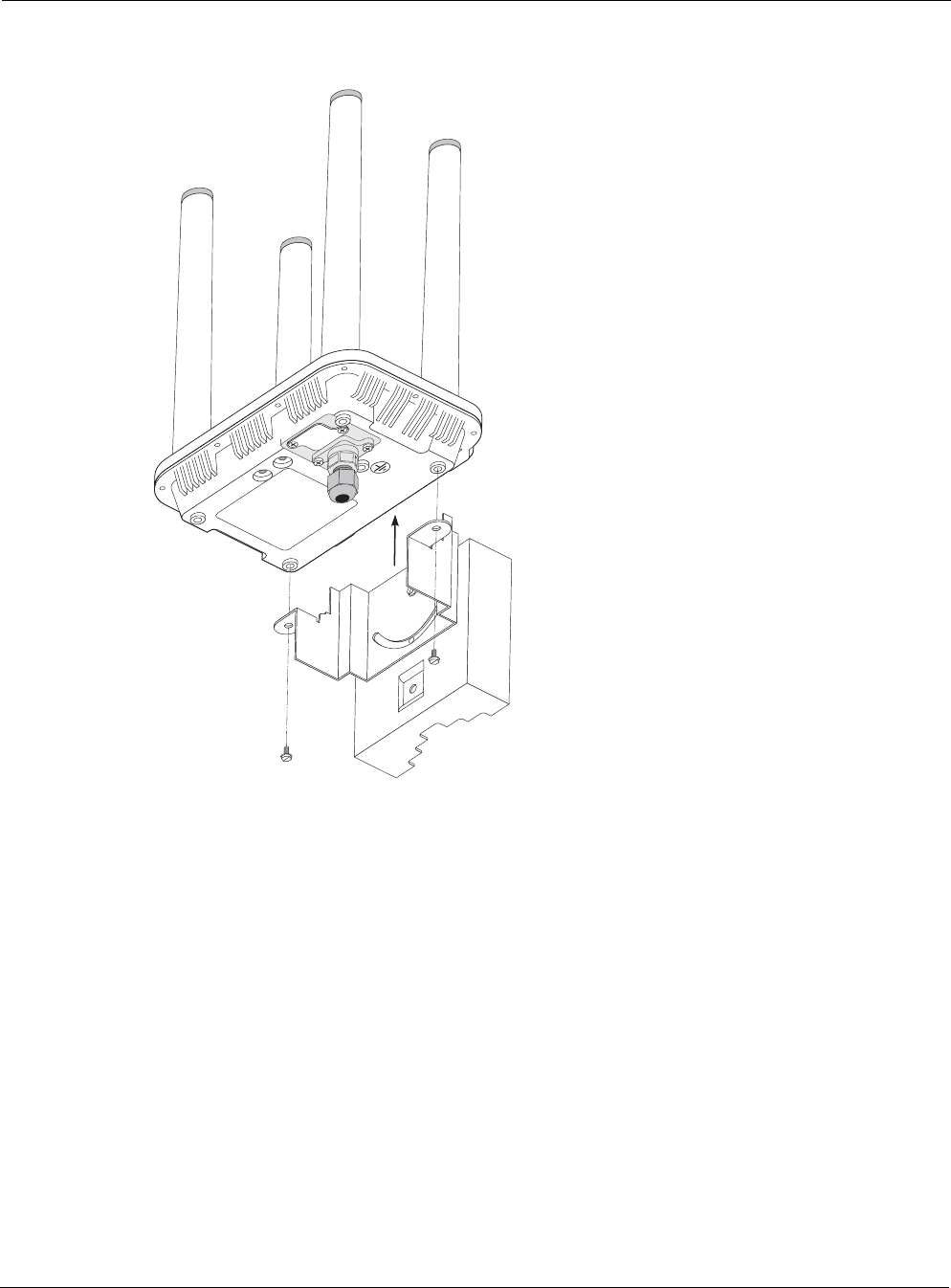
FIGURE 5 Placing the Router on the Mounting Assembly . . . . . . . . . . . . . . . . 23
FIGURE 6 Wood Pole Mounting . . . . . . . . . . . . . . . . . . . . . . . . . . . . . . . . . . . . 24
FIGURE 7 Wood Brace Mounting Option . . . . . . . . . . . . . . . . . . . . . . . . . . . . . 26
FIGURE 8 Tower Mounting . . . . . . . . . . . . . . . . . . . . . . . . . . . . . . . . . . . . . . . . 27
FIGURE 9 Streetlight Mounting . . . . . . . . . . . . . . . . . . . . . . . . . . . . . . . . . . . . . 28
FIGURE 10 Routing the Data/Power Cable to the Router . . . . . . . . . . . . . . . . . 31
FIGURE 11 Data Port Connection . . . . . . . . . . . . . . . . . . . . . . . . . . . . . . . . . . . 31
FIGURE 12 Grounding Arrangement . . . . . . . . . . . . . . . . . . . . . . . . . . . . . . . . . 34
FIGURE 13 Grounding the Indoor Network Protection Unit . . . . . . . . . . . . . . . . 35
FIGURE 14 Deployment Scenarios . . . . . . . . . . . . . . . . . . . . . . . . . . . . . . . . . . . 39
FIGURE 15 Co-Mounting the PS079001 with the Router . . . . . . . . . . . . . . . . . . 41
FIGURE 16 Mounting the PS079001 on a Metal Pole . . . . . . . . . . . . . . . . . . . . 42
FIGURE 17 Mounting the PS079001 on a Wood Pole . . . . . . . . . . . . . . . . . . . . 43
FIGURE 18 Co-Mounting the BBU with the Router . . . . . . . . . . . . . . . . . . . . . . . 45
FIGURE 19 Remote Mounting the BBU on a Metal Pole . . . . . . . . . . . . . . . . . . 46
FIGURE 20 Mounting the BBU on a Wood Pole . . . . . . . . . . . . . . . . . . . . . . . . . 47
FIGURE 21 6410 Power Consumption . . . . . . . . . . . . . . . . . . . . . . . . . . . . . . . . 48
FIGURE 22 6420 Power Consumption . . . . . . . . . . . . . . . . . . . . . . . . . . . . . . . . 49
FIGURE 23 2.4 GHz Antenna Patterns . . . . . . . . . . . . . . . . . . . . . . . . . . . . . . . . 58
FIGURE 24 5 GHz Antenna Patterns . . . . . . . . . . . . . . . . . . . . . . . . . . . . . . . . . 59

Tropos Routers Installation Guide, Models 6410 and 6420 10
List of Tables
TABLE 1 6410 Router Models . . . . . . . . . . . . . . . . . . . . . . . . . . . . . . . . . . . . 11
TABLE 2 6420 Router Models . . . . . . . . . . . . . . . . . . . . . . . . . . . . . . . . . . . . 13
TABLE 3 Ethernet Port Pin Assignments . . . . . . . . . . . . . . . . . . . . . . . . . . . . 32
TABLE 4 Serial Client Scenarios . . . . . . . . . . . . . . . . . . . . . . . . . . . . . . . . . . 32
TABLE 5 Pin Assignments for RJ-45 MGT Port - Serial Clients . . . . . . . . . . . 33
TABLE 6 RF Exposure Information . . . . . . . . . . . . . . . . . . . . . . . . . . . . . . . . . 36
TABLE 7 Ordering Information . . . . . . . . . . . . . . . . . . . . . . . . . . . . . . . . . . . . 39
TABLE 8 6410 Power Consumption (Watts) at Specified Input Voltage . . . . . 48
TABLE 9 6420 Power Consumption (Watts) at Specified Input Voltage . . . . . 49
TABLE 10 Physical Specifications . . . . . . . . . . . . . . . . . . . . . . . . . . . . . . . . . . 50
TABLE 11 Interfaces . . . . . . . . . . . . . . . . . . . . . . . . . . . . . . . . . . . . . . . . . . . . . 52
TABLE 12 Power Options / Consumption . . . . . . . . . . . . . . . . . . . . . . . . . . . . . 54
TABLE 13 Certifications, Other . . . . . . . . . . . . . . . . . . . . . . . . . . . . . . . . . . . . . 54
TABLE 14 PS079001 - Outdoor PoE Injector, non-photocell . . . . . . . . . . . . . . 55
TABLE 15 BB063001 - External Battery Backup Unit . . . . . . . . . . . . . . . . . . . . 55
TABLE 16 Abbreviations . . . . . . . . . . . . . . . . . . . . . . . . . . . . . . . . . . . . . . . . . . 60

Tropos Routers Installation Guide, Models 6410 and 6420 11
1Introduction
This guide explains how to install the Tropos® 6410 and 6420 Mesh routers safely and is
intended for trained technical professionals.
This chapter covers the following topics:
“Tropos 6410 Router Product Summary” on page 11
“Tropos 6420 Router Product Summary” on page 12
Tropos 6410 Router Product Summary
The Tropos 6410 router has the following characteristics:
802.11b/g/n band, 2400-2483 MHz
Support for 802.11b/g/n clients
PoE power input: The Tropos 6410 and 6420 routers are DC powered. There are a number of
methods for connecting power that are described in detail later in this installation manual.
Tropos 6410 and 6420 routers can be powered using:
— 802.3at compliant power applied to the 10/100/1000Base-T (LAN) port
— 11-55VDC power applied to the 10/100Base-T (MGT) port
2 Ethernet ports
— One LAN port for network backhaul communications; this port is a 10/100/1000Base-T
Ethernet port.
— One MGT port for connecting a wired client device; this is either a 10/100BaseT
Ethernet port or a serial port depending on the product. See the model numbers in the
following table. The serial or Ethernet port is factory-installed and cannot be changed in
the field.
Table 1 lists the Tropos 6410 router models.
TABLE 1 6410 Router Models
Model Description
64103000 6410: 2.4GHz; 10/100/1000Base-T + 10/100Base-T; FCC markets
64103000G 6410: 2.4GHz; 10/100/1000Base-T + 10/100Base-T; FCC markets; GPS
64103060 6410: 2.4GHz; 10/100/1000Base-T + serial; FCC markets
64103060G 6410: 2.4GHz; 10/100/1000Base-T + serial; FCC markets; GPS
64103002 6410: 2.4GHz; 10/100/1000Base-T + 10/100Base-T; ETSI markets

Chapter 1
Tropos Routers Installation Guide, Models 6410 and 6420 12
Tropos 6420 Router Product Summary
The Tropos 6420 router has the following characteristics:
802.11a/b/g/n dual band, 2400-2483 MHz/5470-5850 MHz
Support for 802.11a/b/g/n clients
PoE power input: The Tropos 6410 and 6420 routers are DC powered. There are a number of
methods for connecting power that are described in detail later in this installation manual.
Tropos 6410 and 6420 routers can be powered using:
— 802.3at compliant power applied to the 10/100/1000Base-T (LAN) port
— 11-55VDC power applied to the 10/100Base-T (MGT) port
2 Ethernet ports
— One LAN port for network backhaul communications; this port is a 10/100/1000Base-T
Ethernet port (Gigabit Ethernet).
— One MGT port for connecting a wired client device; this is either a 10/100BaseT
Ethernet port or a serial port depending on the product. See the model numbers in the
following table. The serial or Ethernet port is factory-installed and cannot be changed in
the field.
64103002G 6410: 2.4GHz; 10/100/1000Base-T + 10/100Base-T; ETSI markets; GPS
64103062 6410: 2.4GHz; 10/100/1000Base-T + serial; ETSI markets
64103062G 6410: 2.4GHz; 10/100/1000Base-T + serial; ETSI markets; GPS
64103003 6410: 2.4GHz; 10/100/1000Base-T + 10/100Base-T; Global-A markets
64103003G 6410: 2.4GHz; 10/100/1000Base-T + 10/100Base-T; Global-A markets; GPS
64103063 6410: 2.4GHz; 10/100/1000Base-T + serial; Global-A markets
64103063G 6410: 2.4GHz; 10/100/1000Base-T + serial; Global-A markets; GPS
64103004 6410: 2.4GHz; 10/100/1000Base-T + 10/100Base-T; Global-B markets
64103004G 6410: 2.4GHz; 10/100/1000Base-T + 10/100Base-T; Global-B markets; GPS
64103064 6410: 2.4GHz; 10/100/1000Base-T + serial; Global-B markets
64103064G 6410: 2.4GHz; 10/100/1000Base-T + serial; Global-B markets; GPS
TABLE 1 6410 Router Models (continued)
Model Description

Chapter 1
Tropos Routers Installation Guide, Models 6410 and 6420 13
Table 2 lists the Tropos 6420 router models.
TABLE 2 6420 Router Models
Model Description
64203000 6420: 2.4GHz + 5GHz; 10/100/1000Base-T + 10/100Base-T; FCC markets
64203000G 6420: 2.4GHz + 5GHz; 10/100/1000Base-T + 10/100Base-T; FCC markets; GPS
64203060 6420: 2.4GHz + 5GHz; 10/100/1000Base-T + serial; FCC markets
64203060G 6420: 2.4GHz + 5GHz; 10/100/1000Base-T + serial; FCC markets; GPS
64203002 6420: 2.4GHz + 5GHz; 10/100/1000Base-T + 10/100Base-T; ETSI markets
64203002G 6420: 2.4GHz + 5GHz; 10/100/1000Base-T + 10/100Base-T; ETSI markets; GPS
64203062 6420: 2.4GHz + 5GHz; 10/100/1000Base-T + serial; ETSI markets
64203062G 6420: 2.4GHz + 5GHz; 10/100/1000Base-T + serial; ETSI markets; GPS
64203003 6420: 2.4GHz + 5GHz; 10/100/1000Base-T + 10/100Base-T; Global-A markets
64203003G 6420: 2.4GHz + 5GHz; 10/100/1000Base-T + 10/100Base-T; Global-A markets;
GPS
64203063 6420: 2.4GHz + 5GHz; 10/100/1000Base-T + serial; Global-A markets
64203063G 6420: 2.4GHz + 5GHz; 10/100/1000Base-T + serial; Global-A markets; GPS
64203004 6420: 2.4GHz + 5GHz; 10/100/1000Base-T + 10/100Base-T; Global-B markets
64203004G 6420: 2.4GHz + 5GHz; 10/100/1000Base-T + 10/100Base-T; Global-B markets;
GPS
64203064 6420: 2.4GHz + 5GHz; 10/100/1000Base-T + serial; Global-B markets
64203064G 6420: 2.4GHz + 5GHz; 10/100/1000Base-T + serial; Global-B markets; GPS

Tropos Routers Installation Guide, Models 6410 and 6420 14
2Installing the Router
This chapter covers the following topics:
“Preparing for Installation” on page 14
“Mounting Strategies” on page 18
“Proper Use of Clamps” on page 19
“Pole, Tower, and Streetlight Mounting Instructions” on page 20
“Connecting Data and Power Cables” on page 29
“Grounding the Router” on page 34
“Safety and Servicing Information” on page 36
Preparing for Installation
The Tropos 6410 and 6420 routers must be installed by a trained professional, value added
reseller, or systems integrator who is familiar with RF planning issues and regulatory limits
defined by the governing body of the country in which the unit will be installed. This section
explains how to prepare the installation site.
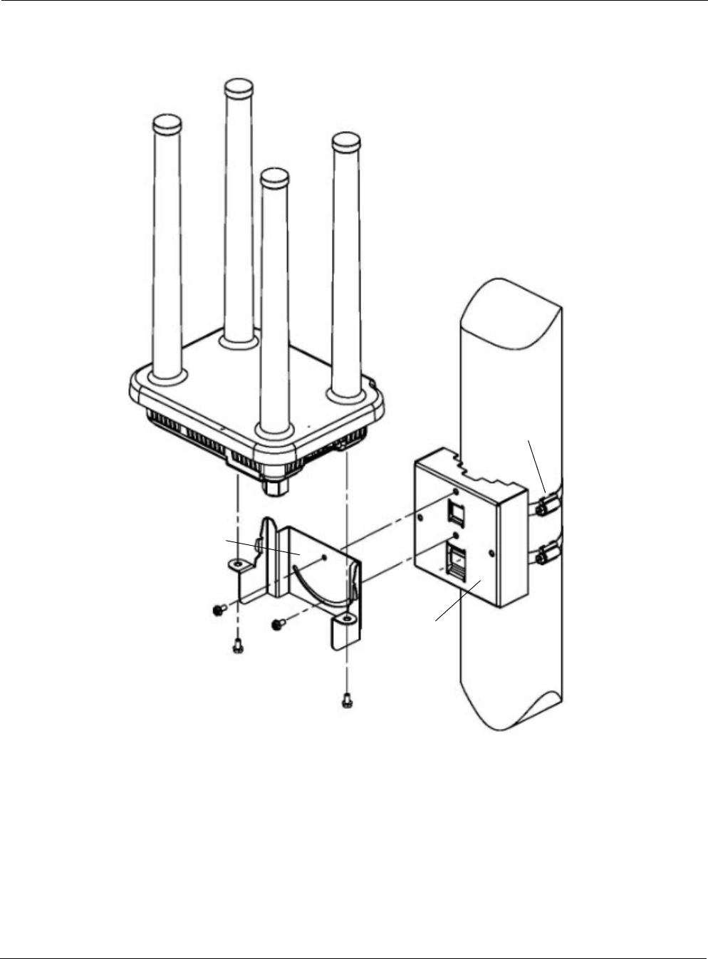
An exploded view of the router assembly is shown in Figure 1.
Note
Operating the unit with non-qualified antennas is a violation of U.S. FCC Rules Part 15.203(c), Code of
Federal Regulations, Title 47.
Chapter 2
Tropos Routers Installation Guide, Models 6410 and 6420 15
FIGURE 1 Tropos 6410/ 6420 Router Exploded View
2.4 GHz Tx/Rx
2.4 GHz Tx/Rx
5 GHz Tx/Rx
5 GHz
Clamps
Pole
Mounting bracket
Tx/Rx
bracket
Router

Chapter 2
Tropos Routers Installation Guide, Models 6410 and 6420 16
Installation Hardware and Tools
The following installation accessories are included in the shipping package:
One pole bracket
Two 4-inch diameter clamps
Two 6-inch diameter clamps
Five 5/16-inch #10-32 stainless steel hex head machine screws
You must supply the following tools:
Level
5/16-inch nut driver
1/4-inch flat blade screwdriver
Tower mounting only: stainless or galvanized steel pipe and 1/2-inch or
5/8-inch nuts, bolts, and washers to connect to the tower arm.
Wood pole mounting only: one 1/4-inch diameter, 3 1/2-inch long lag bolt
Site Planning
To ensure safe and durable wiring, router installation must follow appropriate electrical and
building codes. Follow all local codes and regulations. For example in the U.S., follow the
National Electrical Code (NEC) requirements, unless local codes in your area take precedence
over the NEC code.
The maximum length of Cat 5 cable for 10BaseT, 10/100BaseT, and 10/100/1000BaseT Ethernet
connections is 300 feet (90 meters).
The Ethernet duplex and speed setting is configurable.
Note
The U.S. National Electrical Codes (NEC) Article 800 requires the use of Agency Listed (UL/CSA/TUV)
Building Entrance Protector for all power and data communications cables entering a building. The NEC
intends by Article 800 to protect the building and occupants from fires caused by transient voltage and
current surges.
Note
Ethernet data cable installations having lengths greater than 140 feet in the outdoor environment must use
a UL497 approved (UL/CSA/TUV Listed) primary protection device at the building entrance. Ethernet data
cable installations having lengths less than 140 feet in the outdoor environment may use a UL497A (UL/
CSA/TUV Listed) secondary protection device at the building entrance. Tropos Data Protection Device and
Network Protection Units are UL497A secondary protection devices.

Chapter 2
Tropos Routers Installation Guide, Models 6410 and 6420 17
Location Guidelines
Tropos routers are radio devices and therefore susceptible to interference that can reduce
throughput and range. Follow these guidelines to ensure the best performance:
Install the unit in an area where trees, buildings, and large steel structures do not obstruct
radio signals to and from the antenna. Direct line-of-sight operation is best.
Install the unit away from possible sources of 2.4 GHz and 5 GHz interference, such as
cordless phones, wireless cameras, frequency hopping (FHSS) and DSSS LAN transceivers
(non-802.11), electronic news gathering video links, radars, amateur radios, land mobile
radio services, local government sites (such as law enforcement), fixed microwave services,
local TV transmission, and private fixed point transmitters.
Site Surveys
Due to variations in component configuration, placement, and physical environment, each
installation is unique. Before installing routers, perform a site survey to determine the optimum
placement of units for maximum range, coverage, and network performance. Consider the
following factors when performing a site survey:
Data rates—Sensitivity and range are inversely proportional to data bit rates. The maximum
radio range is achieved at the lowest workable data rate. A decrease in receiver threshold
sensitivity occurs as radio data rate increases.
Antenna orientation—Proper antenna orientation is a critical factor in maximizing radio
range. As a general rule, range increases in proportion to gain and antenna height measured
from the ground. The Tropos 6410 and 6420 routers have integrated antennas; therefore,
antenna location and orientation depend on the location of the unit.
Physical environment—Clear or open areas provide better radio range than closed or filled
areas. The less cluttered the operating environment, the greater the range.
Obstructions—A physical obstruction, such as a building or tree, can block or hinder
communication. Avoid locating antennas in a location where there is an obstruction between
sending and receiving devices.
Building materials—Radio penetration is influenced by the building material used in
construction. For example, drywall construction permits greater range than concrete blocks.
Safety
Installing the routers can pose a serious hazard. Be sure to take precautions to avoid the
following:
Exposure to high voltage lines during installation
Falls when working at heights or with ladders
Injuries from dropping tools and equipment
Contact with AC power wiring
Chapter 2
Tropos Routers Installation Guide, Models 6410 and 6420 18
Mounting Strategies
When choosing mounting locations, consider the available mounting structures and antenna
clearance. The router should always be mounted with the top of the unit horizontal and level and
with the antennas facing upward.
It is usually best to attach ground and data cables to the router prior to mounting. Before
mounting the router, review the wiring instructions in “Grounding the Router” on page 34 and
“Connecting Data and Power Cables” on page 29 to determine the best strategy for the selected
location.
Note
To eliminate potential interference from the mounting structure, the router should be mounted
with at least 4 feet of clearance around the antennas.
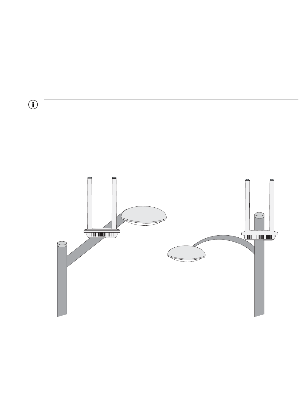
Acceptable options for mounting on a streetlight are shown in Figure 2. In each case the router is
mounted to assure clearance for the antennas above the height of the streetlight.
FIGURE 2 Example Mounting Location - Antennas Facing Upward
Antennas clear of obstruction
Antennas clear
of obstruction
Chapter 2
Tropos Routers Installation Guide, Models 6410 and 6420 19
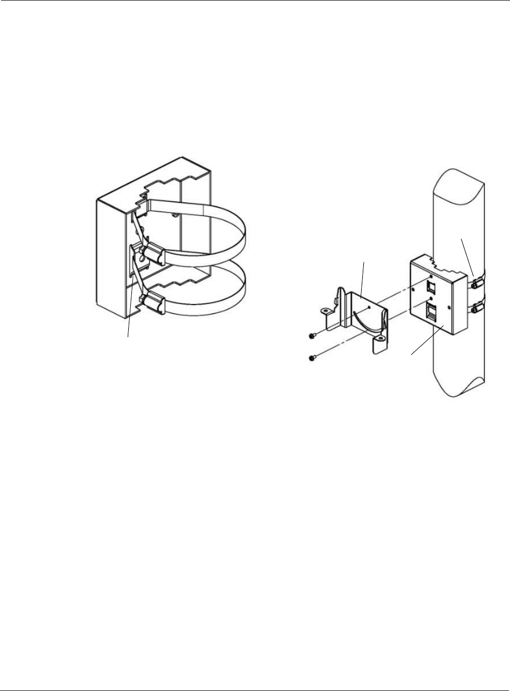
Proper Use of Clamps
The mounting assembly contains two clamps to secure the router to the mounting structure.
Figure 3 illustrates the proper use of the clamps. The clamps must be routed through slots in the
pole bracket as shown in the figure, and then attached to the pole and tightened.
The pole bracket should be leveled before it is secured to the pole.
FIGURE 3 Proper Use of the Clamps
Band goes
behind inner tabs
Clamps
Pole
Mounting bracket
bracket

Chapter 2
Tropos Routers Installation Guide, Models 6410 and 6420 20
Pole, Tower, and Streetlight Mounting Instructions
This section explains how to mount the router on a pole, tower, or streetlight. It is best to mount
the router to aluminum or galvanized steel structures. The mounting brackets are designed to
pierce any oxidation layers that are on the outside of the pole, thereby assuring good quality
connection to the grounded structure.
Due to potential antenna obstruction issues, the router is not designed to be directly mounted on
a building wall. If it is necessary to mount the router on a wall, follow the instructions for
mounting on a wooden pole (“Wood Pole Mounting” on page 24), and attempt to mount the
router with maximum possible clearance around the antennas.
Note
The router should always be mounted with the top of the router horizontal and level and with the antennas
facing upward.
Note
It is best to attach ground and data cables to the router before sliding the router into the mounting bracket,
as explained in this section. Before mounting the router, review the wiring instructions in “Grounding the
Router” on page 34 and “Connecting Data and Power Cables” on page 29 to determine the best strategy
for the selected location.
Note
Mounting to wood, concrete, or painted poles may require primary grounding for the unit. Check the
national electrical codes in your area for specific rules.

Chapter 2
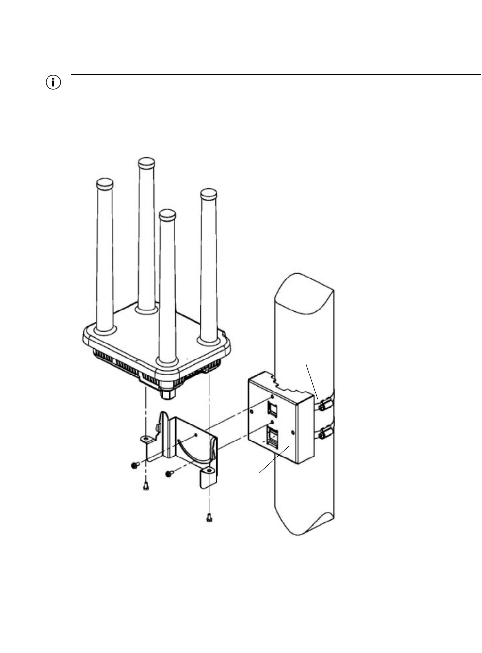
Tropos Routers Installation Guide, Models 6410 and 6420 22
Mount the router on a metal pole
1. Select a mounting location. You can attach the router to any pipe or pole with diameter
between 1 inch and 10 inches.
2. Slip the flat portion of each clamp under the inner slot of the pole bracket.
3. Use the clamps to attach the pole bracket to the pole, making sure that they are level.
Depending upon the diameter of the pole, you may need to use small clamps, large clamps,
or pairs of large clamps joined together to reach around the pole.
4. Attach the mounting bracket of the router to the pole bracket with two 5/16-inch machine
screws (refer to Figure 4 for the correct orientation):
— Insert one screw through the hole at the top of the mounting bracket to the hole at the top
of the pole bracket.
— Insert the other screw through the curved slot track in the mounting bracket to the hole in
the middle of the pole bracket just above the clamp slots.
5. Level the mounting bracket by rotating the unit along the curved slot tracks. Tighten the
screws.
6. Place the upright router onto the top of the mounting bracket, as shown in Figure 5. Secure
the mounting bracket to the router by attaching two 5/16-inch machine screws through the
holes in the mounting bracket tabs to corresponding holes on the bottom of the router.

Chapter 2
Tropos Routers Installation Guide, Models 6410 and 6420 25
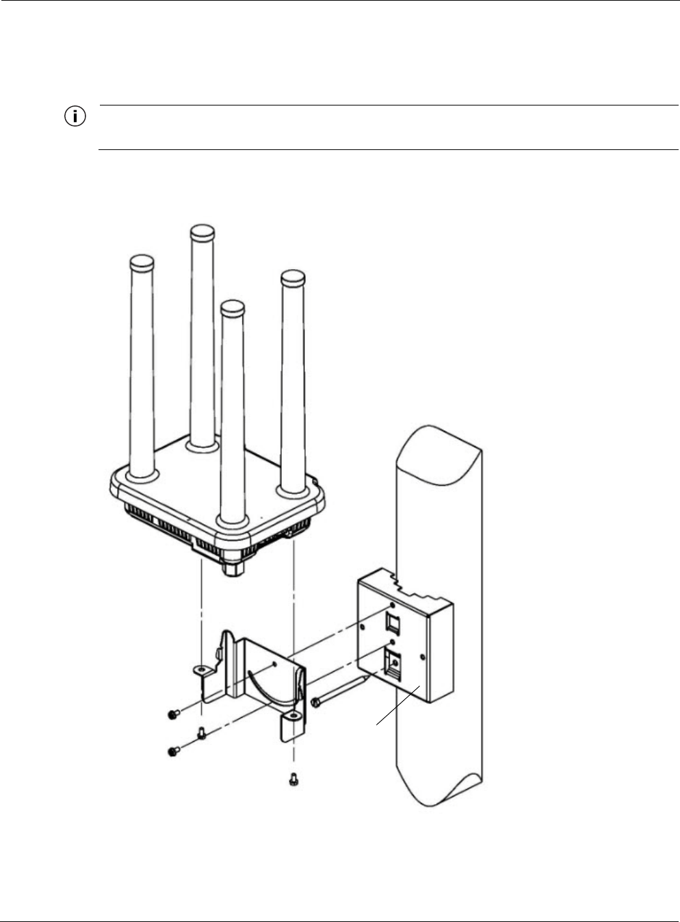
Mount the router on a wood pole
1. Select a mounting location. You can attach the router to any outdoor wood pole of diameter
at least 1 inch.
2. Attach the pole bracket to the pole by threading a 1/4-inch bolt through the hole in the lower
clamp slot to the pole. The bolt should be at least 3 1/2 inches in length. Make sure that the
bracket is level.
3. Attach the mounting bracket of the router to the pole bracket with two 5/16-inch machine
screws (refer to Figure 4 for the correct orientation):
— Insert one screw through the hole at the top of the mounting bracket to the hole at the top
of the pole bracket.
— Insert the other screw through the curved slot track in the mounting bracket to the hole in
the middle of the pole bracket just above the clamp slot.
4. Level the mounting bracket by rotating the unit along the curved slot tracks. Tighten the
screws.
5. Place the upright router onto the top of the mounting bracket, as shown in Figure 5 on page
23. Secure the mounting bracket to the router by attaching two 5/16-inch machine screws
through the holes in the mounting bracket tabs to corresponding holes on the bottom of the
router.
To continue installing the router, see “Connecting Data and Power Cables” on page 29.
Chapter 2
Tropos Routers Installation Guide, Models 6410 and 6420 26
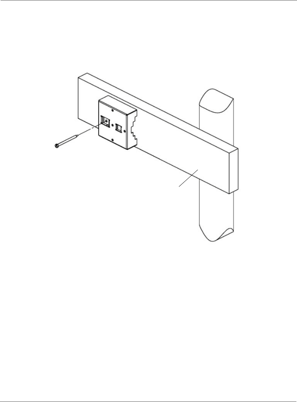
Wood Brace Mounting
You can mount the pole bracket directly on a wood brace without using clamps, as shown in
Figure 7.
FIGURE 7 Wood Brace Mounting Option
Mount the router on a wood pole
1. Select a mounting location. You can attach the router to any wood brace.
2. Attach the pole bracket to the wood brace with two 1/4-inch lag bolts that are at least 3 1/2
inches in length, making sure that the wood brace is level.
3. Attach the mounting bracket of the router to the pole bracket with two 5/16-inch machine
screws (refer to Figure 4 for the correct orientation):
— Insert one screw through the hole at the top of the mounting bracket to the hole at the top
of the pole bracket.
— Insert the other screw through the curved slot track in the mounting bracket to the hole in
the middle of the pole bracket just above the clamp slot.
4. Level the mounting bracket by rotating the unit along the curved slot tracks. Tighten the
screws.
Wood
brace
1/4” lag bolt
3-1/2” minimum
Chapter 2
Tropos Routers Installation Guide, Models 6410 and 6420 27
5. Place the upright router onto the top of the mounting bracket, as shown in Figure 5 on page
23. Secure the mounting bracket to the router by attaching two 5/16-inch machine screws
through the holes in the mounting bracket tabs to corresponding holes on the bottom of the
router.
To continue installing the router, see “Connecting Data and Power Cables” on page 29.
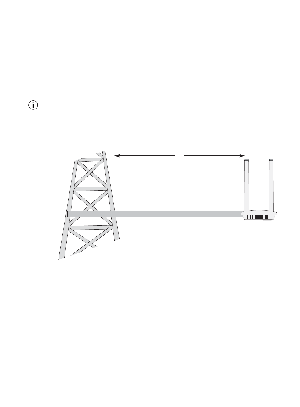
Tower Mounting
You can mount the router on an outdoor tower.
Note
At the antenna level, the router must be free from metal obstruction within a 4-foot radius (Figure 8).
FIGURE 8 Tower Mounting
Mount the Tropos router on a tower
1. Remove the pole bracket from the mounting bracket, if they are attached.
2. Make a tower bracket by attaching the mounting bracket directly to any stainless steel or
galvanized steel pipe.
3. Attach the mounting bracket to the tower arm so that the top of the shield is horizontal and
level.
4. Tighten the mounting bolts.
5. Place the upright router onto the top of the mounting bracket, as shown in Figure 5 on page
23. Secure the mounting bracket to the router by attaching two 5/16-inch machine screws
through the holes in the mounting bracket tabs to corresponding holes on the bottom of the
router.
To continue installing the router, see “Connecting Data and Power Cables” on page 29.
4'
Brackets not included
1 1/2'' minimum diameter pipe
Chapter 2
Tropos Routers Installation Guide, Models 6410 and 6420 28
Streetlight Mounting
You can mount the router on the horizontal or angled arm of a streetlight. Figure 9 shows a
typical streetlight mounting installation.
FIGURE 9 Streetlight Mounting
Mount the router on a streetlight
1. Select a mounting location. You can attach the router to any streetlight arm with diameter 1”
to 10”.
2. Slip the flat portion of each clamp under the inner slot of the pole bracket.
3. Use the clamps to attach the pole bracket to the arm, making sure that they are level.
Depending upon the diameter of the arm, you may need to use small clamps, large clamps,
or pairs of large clamps joined together.
Pole
bracket
Router

Chapter 2
Tropos Routers Installation Guide, Models 6410 and 6420 29
4. Attach the mounting bracket of the router to the pole bracket with two 5/16-inch machine
screws (refer to Figure 4 for the correct orientation):
— Insert one screw through the hole at the top of the mounting bracket to the hole at the top
of the pole bracket.
— Insert the other screw through the curved slot track in the mounting bracket to the hole in
the middle of the pole bracket just above the clamp slot.
5. Level the mounting bracket by rotating the unit along the curved slot tracks. Tighten the
screws.
6. Place the upright router onto the top of the mounting bracket, as shown in Figure 5 on page
23. Secure the mounting bracket to the router by attaching two 5/16-inch machine screws
through the holes in the mounting bracket tabs to corresponding holes on the bottom of the
router.
To continue installing the router, see the next section, “Connecting Data and Power Cables.”
Connecting Data and Power Cables
The router is equipped with two RJ45 ports.
LAN. The port labeled LAN is a 10/100/1000Base-T Ethernet port normally used for a
network backhaul connection. The router can be powered over this port using industry-
standard 802.3at PoE (Power over Ethernet) power (do not use any other form of PoE power
on this port). This port can also be used to configure the router.
MGT. The port labeled MGT is one of two types, depending on the specific Tropos 6410 or
6420 model. See the model number descriptions in “Tropos 6410 Router Product Summary”
on page 11 and “Tropos 6420 Router Product Summary” on page 12. If you have any
questions about models or configuration, contact Tropos Customer Support
(tropos.support@nam.abb.com).
— On some models the MGT port is a 10/100/1000Base-T Ethernet port used for
configuration and for connecting a wired Ethernet client to the router.
— On some models the MGT port is a serial port that is capable of supporting RS-232 or
RS-485 serial clients.
The router can be powered over the MGT port using DC power in the range 11-55VDC (see
pin assignments on the RJ-45 connector in Table 3).
This section describes how to connect the Ethernet cables.
Note
The router is shipped pre-configured. For post-installation changes in configuration, you can communicate
with the router by way of its wireless connection. For more information, see the Tropos Networks User
Guide.
Chapter 2
Tropos Routers Installation Guide, Models 6410 and 6420 30
Note
Only use shielded Cat5, Cat5e, or Cat6 cable rated for outdoor use. For protection against risk of fire,
electrical hazard and to ensure the reliable operation of this equipment, the shields of the Cat5 cable must
be properly terminated and bonded to the unit and to the protective earth (PE) at the building entrance.
Note
National Electrical Codes (NEC) Article 800 requires the use of Agency Listed (UL/CSA) Building Entrance
Protector for all power and communications cables entering a building. The NEC intends by Article 800 to
protect the building and occupants from fires caused by transient voltage and current surges.
Warning
DC voltage may be present on RJ45 pins 4,5 (+) and 7,8 (-).
Attention
Une tension continue peut être présente sur les broches RJ45 4, 5 (+) et 7, 8 (-).
Note
This is not a mid-span powered device. Never attempt to daisy-chain Power Over Ethernet devices.
Connecting the Ethernet cable through the watertight gland
Use the following procedure to connect an Ethernet cable and RJ-45 connector to either the LAN
or MGT port. Use the pin assignments in Table 3.
1. Have the Ethernet data cable, nut, rubber boots, and cable gland available.
2. Remove the cable gland from the bottom of the router. Determine the port to use (see
Figure 11).
3. Press the tab on the RJ45 connector down as you push the cable through the nut. Make sure
that the orientation is consistent with Figure 10.
4. Separate the rubber boot as needed and slide the connector through the boot. Use the boot
with the smaller diameter opening, unless the cable is too wide to permit the boot to close
completely.
5. Slide the cable through the cable gland, as shown in Figure 10.
Chapter 2
Tropos Routers Installation Guide, Models 6410 and 6420 31
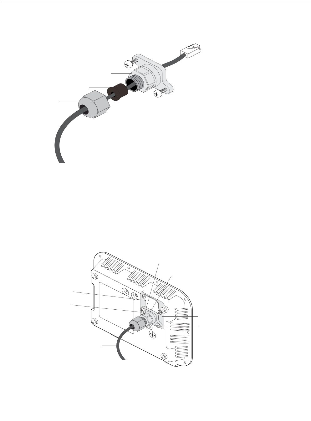
FIGURE 10 Routing the Data/Power Cable to the Router
6. Plug the cable into the appropriate port on the router.
7. Screw the cable gland onto the bottom of the router, and then slide the nut over the rubber
boot and screw both tightly to the cable gland. Tighten the nut to ensure a positive water
seal. Figure 11 shows how the cable assembly is attached to the bottom of the router.
FIGURE 11 Data Port Connection
Nut
Cable gland
Rubber boot
Shielded outdoor
cat5 cable
drip loop
Shield termination
Cable gland
(watertight)
Tighten two screws to
fasten cable gland
Access area
LAN port
(includes power)
MGT port
Chapter 2
Tropos Routers Installation Guide, Models 6410 and 6420 32
Ethernet Ports
The pin assignments on the Ethernet ports (the LAN port on all models and the MGT port on
models where the MGT port is an Ethernet port) are industry-standard. They are shown in the
following table.
Note
Use Cat6 cable for Gigabit Ethernet.
Serial Ports
Tropos 6410 and 6420 routers that are equipped with serial ports can support serial clients on
RS-232 or RS-485 interfaces. The serial port can also be used to power the router.
The router can support the following serial client scenarios. Before installation determine the
installation scenario and the appropriate powering option for that scenario.
TABLE 3 Ethernet Port Pin Assignments
Pin LAN Port
10/100/1000Base-T MGT Port
10/100Base-T
1 TxRx_A+ Tx +
2 TxRx_A- Tx -
3 TxRx_B+ Rx +
4 TxRx_C+ Power +
5 TxRx_C- Power +
6 TxRx_B- Rx -
7 TxRx_D+ Power -
8 TxRx_D- Power -
TABLE 4 Serial Client Scenarios
Wired Serial Client Scenario Recommended Wiring
one RS-232 serial client • Connect the wired client to the MGT port on the router
according to the pin assignments in Table 5.
• Provide power to the router on the MGT port according to
the pin assignments in Table 5.

Chapter 2
Tropos Routers Installation Guide, Models 6410 and 6420 33
The following are the pin assignments for the RJ-45 MGT port when used for serial clients.
two RS-232 serial clients • Connect the RS-232 serial clients to the MGT port on the
router according to the pin assignments in Table 5.
• Provide power to the 1410 on the LAN port (note: in this sce-
nario the power applied to the LAN port must be from a stan-
dard 802.3at power supply)
one RS-485 client • Connect the RS-485 client to the MGT port on the router
according to the pin assignments in Table 5.
one RS-232 serial client
one RS-485 serial client • Connect the RS-232 and RS-485 clients to the MGT port on
the router according to the pin assignments in Table 5.
• Provide power to the 1410 on the LAN port (note: in this sce-
nario the power applied to the LAN port must be from a stan-
dard 802.3at power supply)
TABLE 5 Pin Assignments for RJ-45 MGT Port - Serial Clients
Pin Option 1 (one serial port) Option 2 (two serial ports)
1 RS232 TX or RS485 TXRX + RS232 (port 1) TX or RS485 TXRX +
2GND GND
3 RS232 RX or RS485 TXRX - RS232 (port 1) RX or RS485 TXRX -
4 Power + not used
5 Power + RS-232 (port 2) RX
6 not used RS-232 (port 2) TX
7 Power - not used
8 Power - not used
TABLE 4 Serial Client Scenarios (continued)
Wired Serial Client Scenario Recommended Wiring
Chapter 2
Tropos Routers Installation Guide, Models 6410 and 6420 34
Grounding the Router
Caution
You must install an external grounding wire if the router is installed on a non-metal pole or if the
metal installation structure is not properly grounded. You must also ground the outdoor data
protection device to a bonded pipe or ground rod. Make sure that grounding is complete before
you connect power to the router.
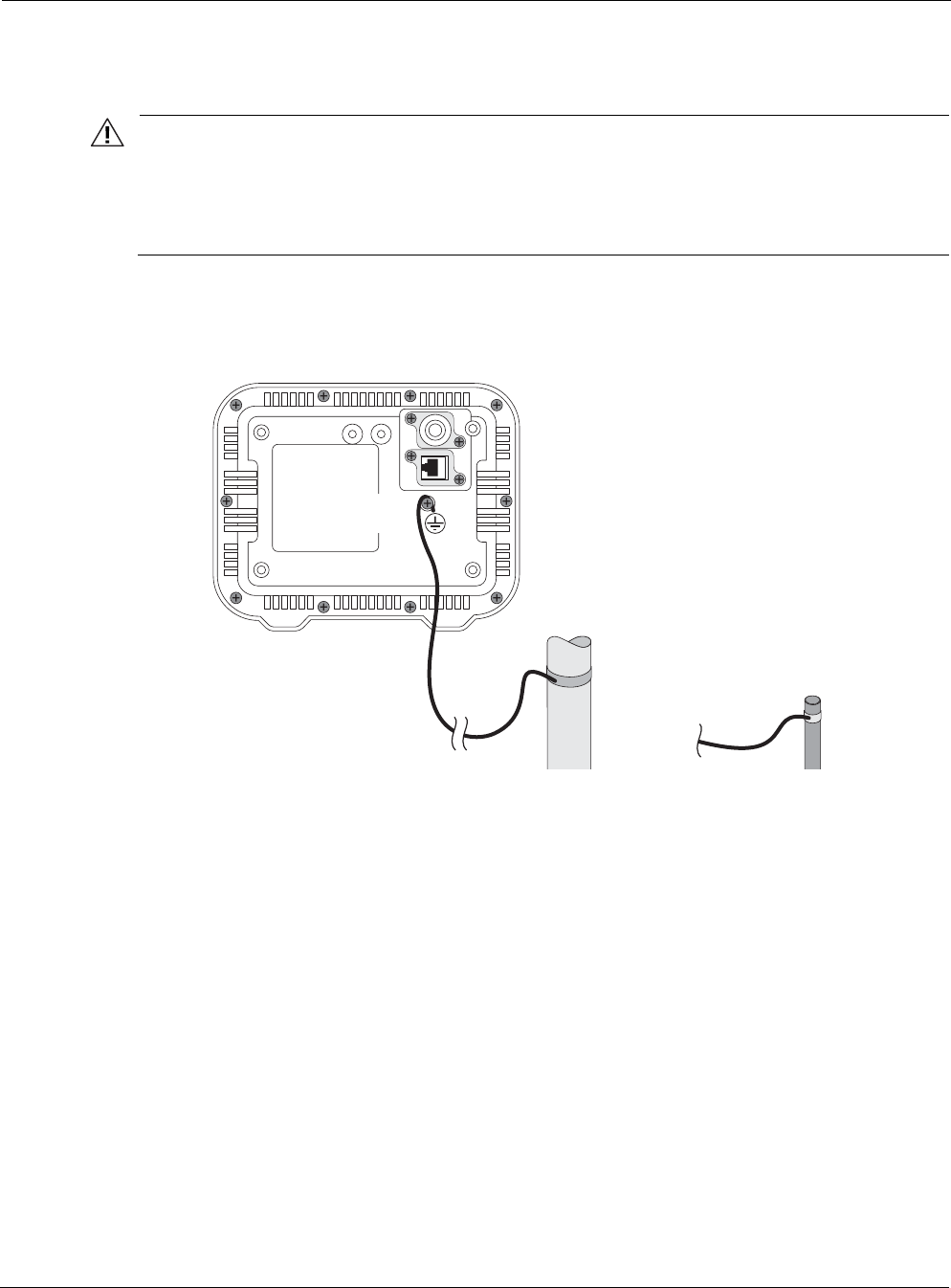
The grounding arrangement for the router is shown in Figure 12.
FIGURE 12 Grounding Arrangement
Ground the router
1. Insert the grounding screw into the grounding screw hole on the bottom of the router.
2. Connect a length of #10 AWG bare copper wire to the grounding screw and tighten.
3. Connect the other end of the grounding wire to a grounding strap that is attached to a
grounded surface or other earth ground, such as a grounding rod.
10 AWG wire
to ground
Grounding strap
on pipe or grounding rod
Grounding
screw

Chapter 2
Tropos Routers Installation Guide, Models 6410 and 6420 35
Grounding the Data Protection Device
The grounding arrangement for an indoor data protection device is shown in Figure 13.
Ground an indoor data protection device
1. Place the protection device as close to the building entrance as possible.
2. Connect a length of #10 AWG bare copper wire to the ground post on the data protection
device.
3. Connect the other end of the grounding wire to the ground connection of an electrical outlet
or a grounded water pipe.
FIGURE 13 Grounding the Indoor Network Protection Unit
10 AWG wire
to ground
Grounding wire
to elecrtical outlet ground
or water pipe
Indoor network
protection unit
To network
Data cable enters
building wall
through conduit
Shielded RJ45 ports
Chapter 2
Tropos Routers Installation Guide, Models 6410 and 6420 36
Safety and Servicing Information
This section contains safety and servicing information.
RF Exposure Information
The Federal Communications Commission (FCC) with its action in ET Docket 96-8 has adopted
a safety standard for human exposure to RF electromagnetic energy emitted by FCC certified
equipment. The Tropos 6410 and 6420 routers meet the uncontrolled environmental limits found
in OET-65 and ANSI C95.1, 1991. Proper operation of this device according to the instructions
found in this manual and the hardware and software guides on the router results in user exposure
that is substantially below the FCC recommended limits.
In order to meet the human RF exposure limits required by FCC and Industry Canada, the
installer shall insure separation between transmitter antennas. All persons should maintain a
minimum distance from the router as specified in Table 6.
Warning
It is illegal to modify the construction of this product. Modifying the operating frequency or enhancing the transmit output
power through the use of external amplifiers or other equipment is specifically disallowed by the “Telecommunications Act.”
Warning
This device is for outdoor or indoor use with conditions that no harmful interference to authorized radio stations results from
the operation of this device. This device shall not influence aircraft security and/or interfere with legal communications as
defined in the “Telecommunications Act.” If this device is found to cause interference, the operator of this equipment shall
cease operating this device immediately until no interference is achieved.
Safety Guidelines
Follow these guidelines to ensure safe operation of the router:
Do not touch or move the antennas while the unit is transmitting or receiving.
Do not hold any component containing a radio such that the antenna is very close to or
touching any exposed parts of the body, especially the face or eyes, while transmitting.
Do not operate the radio or attempt to transmit data unless the antenna is connected;
otherwise, the radio may be damaged.
TABLE 6 RF Exposure Information
Model Radios, RF Band Antennas Maximum EIRP Minimum Distance
6410 Single 2.4 GHz Internal 2.4 GHz EIRP, 34.5 dBm 20 cm (8 in)
6420 Dual 2.4 GHz/5.8
GHz
Internal 2.4 GHz EIRP, 34.5 dBm
5.8 GHz EIRP, 34 dBm
22 cm (9 in)

Chapter 2
Tropos Routers Installation Guide, Models 6410 and 6420 37
Use in specific environments:
— Do not operate a portable transmitter near unshielded blasting caps or in an explosive
environment unless it is a type especially qualified for such use.
— The use of wireless devices in hazardous locations is limited to the constraints posed by
the safety directors of such environments.
— The use of wireless devices on airplanes is governed by the Federal Aviation
Administration (FAA).
— The use of wireless devices in hospitals is restricted to the limits set forth by each
hospital.
Servicing the Router
The router has no user serviceable parts inside. For any service-related issues, contact Tropos
Customer Support (support@tropos.com).

Tropos Routers Installation Guide, Models 6410 and 6420 38
3Installing Battery and Power Backup
Accessories
This chapter describes how to install battery and power backup accessories:
“Introduction” on page 38
“Installing the PS079001” on page 40
“Installing the Battery Backup Unit” on page 44
Introduction
The Tropos 6410 and 6420 routers are designed to operate from DC power sources. If DC
power is not available, Tropos offers power solutions for the 6410 and 6420 for photocell and
non-photocell applications and a battery backup unit that provides backup power for the routers.
The following products are available.
PS079001 - Outdoor PoE Injector, non-photocell
The PS079001 is used for all non-streetlight applications. AC power is provided to the
PS079001 using a PT031006 (6 feet) or PT031030 (30 feet) Tropos power cable. For streetlight
installations where a photocell can be used as the AC power source, Tropos offers the PT021004
(4 feet) and PT021020 (20 feet) power cables. These cables have a photocell tap at one end and
a connector on the other end to plug into the PS079001.
The PS079001 can be mounted on the mounting bracket of the router or can be remotely
mounted.
The PS079001 provides an Ethernet port that connects to the MGT port on the router, allowing
the router to function as a gateway.
BB063001 - External Battery Backup Unit
The BB063001 Battery Backup Unit (BBU) provides backup power for a Tropos 6410 or 6420
fixed router. The BB063001 requires the use of one of the two Tropos power supplies described
above.
The BB063001 can be mounted on the mounting bracket of the router (when a TLP4820 or
PS079001 is used) or can be remotely mounted.
The PS079001 provides an Ethernet port that connects to the MGT port on the router allowing
the router to function as a gateway.
Chapter 3
Tropos Routers Installation Guide, Models 6410 and 6420 39
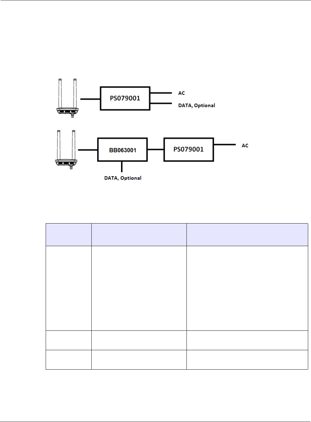
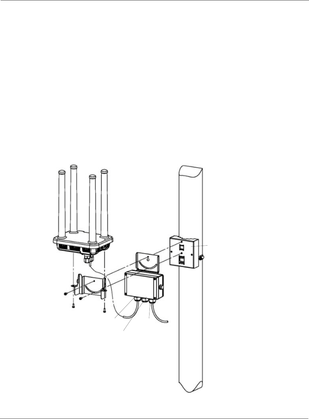
The deployment scenarios are shown in Figure 14. When using the BB063001 BBU, it should be
mounted on the mounting bracket of the 6420/6410 router. When using the PS079001 PoE
injector without the BB063011, it can be mounted on the mounting bracket of the
6420/6410 router. The PS079001must be remote mounted when used with the BB063001.
FIGURE 14 Deployment Scenarios
Table 7 lists ordering information.
TABLE 7 Ordering Information
Part Number Description Required Components
Ordered Separately
PS079001 Outdoor PoE Injector, non-photocell Power cable, one of the following:
• PT021004 power cable, 4 feet, 2-wire, pho-
tocell
• PT021020 power cable, 20 feet, 2-wire,
photocell
• PT031006 power cable, 6ft, 3-wire, water-
tight plug
• PT031030 power cable, 30ft, 3-wire, water-
tight plug,
MB008003 mounting bracket kit (if required)
BB063001 External Battery Backup Unit • Outdoor rated Ethernet cables
• PS079001 power supply
MB008003 Kit, mounting bracket, PS079001/
BBU063001

Chapter 3
Tropos Routers Installation Guide, Models 6410 and 6420 40
Installing the PS079001
Follow the guidelines in this section when installing the PS079001:
“Tools Required” on page 44
“Installation Procedures” on page 45
Tools Required
Wrench, 1/2 inch or 13mm
5/16 nut driver
Wrench, 9/16 inch but only when using 3/8" lag
Chapter 3
Tropos Routers Installation Guide, Models 6410 and 6420 41
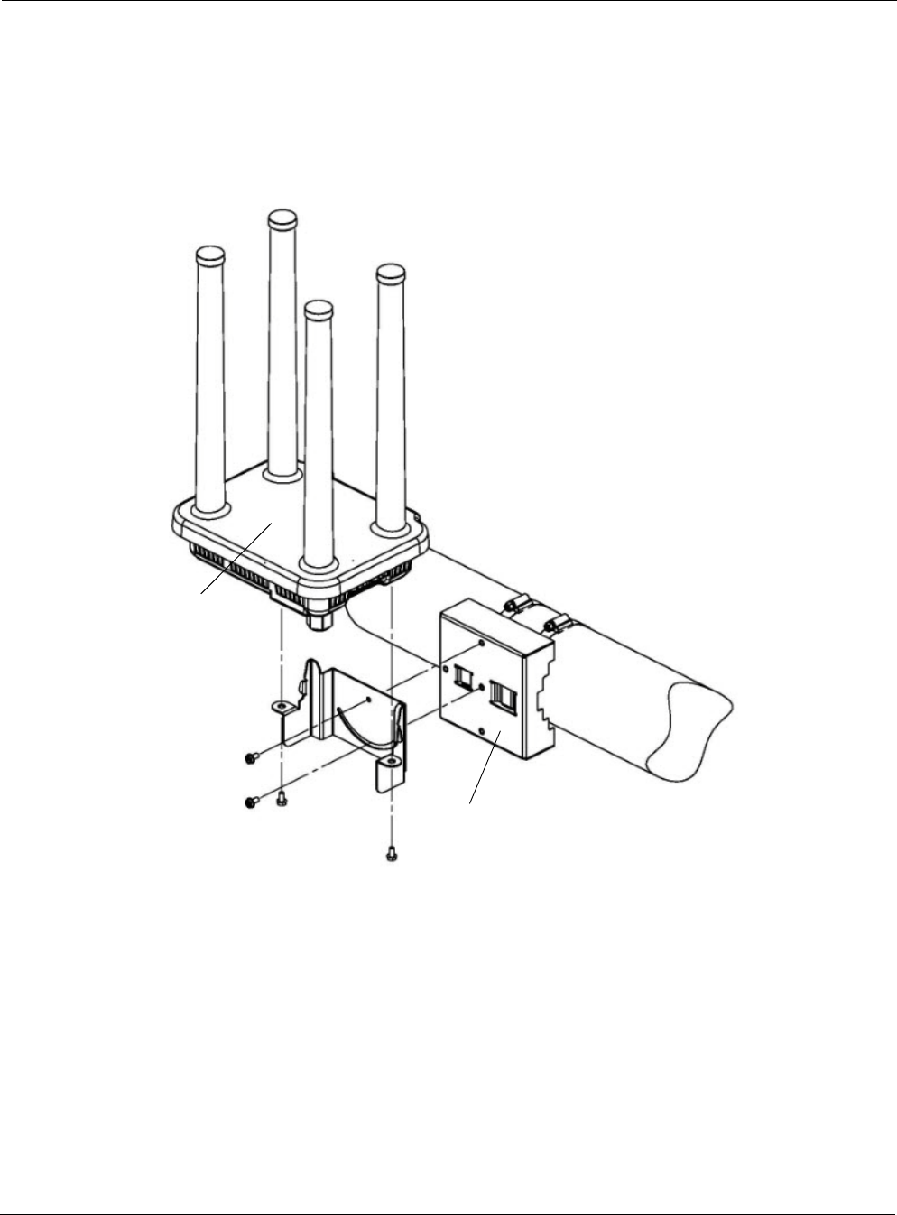
Installation Procedures
You can co-mount the PS079001 with the router or mount the PS079001 separately on a metal or
wood pole. When used with the BB063001 Battery Backup Unit (BBU), the PS079001 should
be mounted remotely.
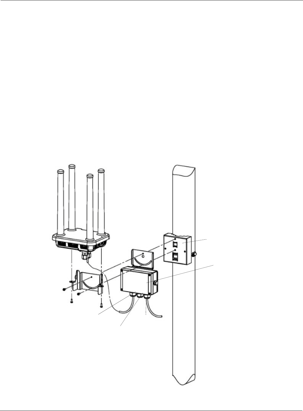
Co-mount the PS079001 with the router
1. Follow the instructions in Chapter 2, “Installing the Router,” to secure the pole bracket to the
pole.
2. Place the PS079001 mounting bracket between the pole bracket and the router mounting
bracket. Secure with two each 10-32 screws (Figure 15).
3. Mount and secure the router to the mounting bracket with two each 10-32 screws.
4. Connect the PoE + LAN output cable to the BBU LAN output port.
5. Attach the PoE input cable to the PoE input port.
FIGURE 15 Co-Mounting the PS079001 with the Router
PS079001
Data and AC power
MGT port
Router
plate
PS079001
input
mounting
Data in
power out
(to 6420
or BB 063001)
Pole bracket
(supplied with the router)
Chapter 3
Tropos Routers Installation Guide, Models 6410 and 6420 42
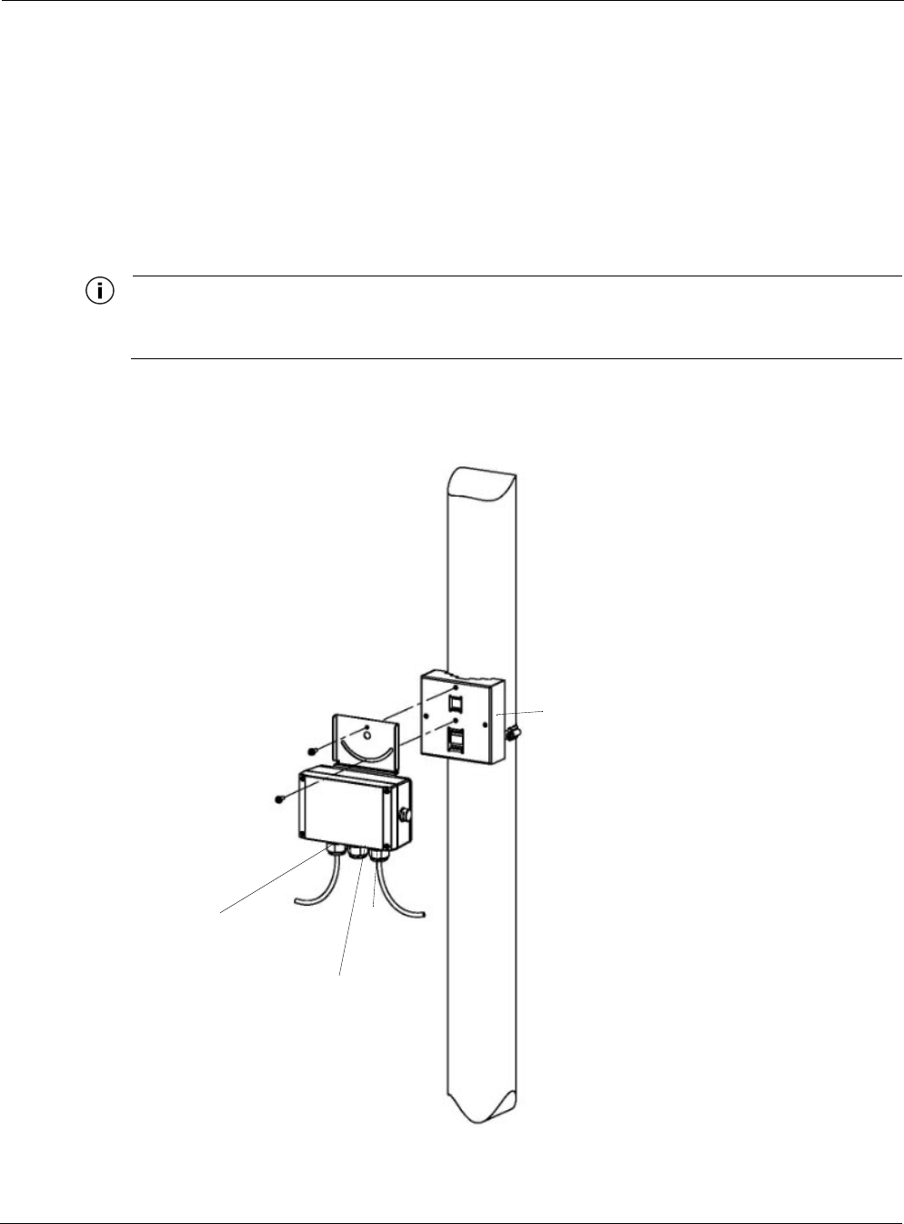
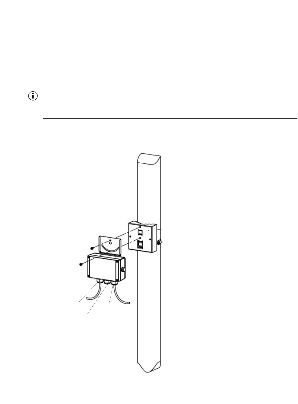
Remote mount the PS079001 on a metal pole
1. Use the hose clamp to secure the pole bracket to the pole, as shown in Figure 4 on page 21.
2. Secure the PS079001 mounting bracket to the pole bracket. Secure with two each 10-32
screws (Figure 16).
3. Connect the PoE + LAN output cable from the PS079001 LAN output port to the MGT port
on the router.
4. Attach the PoE input cable to the PoE input port.
Note
When the PS079001 is remotely mounted, the data and power out cable supplied with the unit must be
replaced with an outdoor-rated Ethernet cable of sufficient length.
FIGURE 16 Mounting the PS079001 on a Metal Pole
PS079001 mounting
plate
BBU
Data and AC power
input
Data in
power out
(to 6420
or BB 063001)
Pole bracket
(requires pole mount kit)

Chapter 3
Tropos Routers Installation Guide, Models 6410 and 6420 43
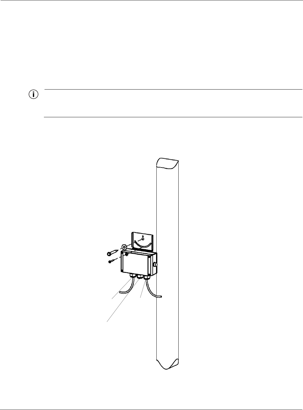
Remote mount the PS079001 on a wood pole
1. Secure the PS079001 mounting plate to the pole by threading a 1/4-inch bolt through the
hole in the clamp slot to the pole. The bolt should be at least 3 1/2 inches in length. Make
sure that the bracket is level (Figure 17).
2. Connect the PoE + LAN output cable from the PS079001 LAN output port to the MGT port
on the router.
3. Attach the PoE input cable to the PoE input port.
Note
When the PS079001 is remotely mounted, the data and power out cable supplied with the unit must be
replaced with an outdoor-rated Ethernet cable of sufficient length.
FIGURE 17 Mounting the PS079001 on a Wood Pole
PS079001 mounting
plate
PS079001
Data and
AC power
input
Data in
power out
(to 6420
or BB 063001)

Chapter 3
Tropos Routers Installation Guide, Models 6410 and 6420 44
Installing the Battery Backup Unit
Follow the guidelines in this section when installing the battery backup unit (BBU):
“Tools Required” on page 44
“Installation Procedures” on page 45
Tools Required
Wrench, 1/2 inch or 13mm
5/16 nut driver
Wrench, 9/16 inch but only when using 3/8" lag
Chapter 3
Tropos Routers Installation Guide, Models 6410 and 6420 45
Installation Procedures
You can co-mount the BBU with the router (preferred) or mount the BBU separately on a metal
or wood pole. When using both the BBU063001 and the PS079001, the BBU must be co-
mounted with the 6420 router and the PS079001 mounted on the pole or other surface.
Co-mount the BBU with the router
1. Follow the instructions in Chapter 2, “Installing the Router,” to secure the pole bracket to the
pole.
2. Place the BBU mounting bracket between the pole bracket and the router mounting bracket.
Secure with two each 10-32 screws (Figure 18).
3. Mount and secure the router to the mounting bracket with two each 10-32 screws.
4. Connect the PoE + LAN output cable to the BBU LAN output port.
5. Attach the PoE input cable to the PoE input port.
FIGURE 18 Co-Mounting the BBU with the Router
BBU mounting
PoE Input
MGT port
Router
plate
BBU
from
PS079001
Data and power
Data in
out (to 6420)
Pole bracket
Chapter 3
Tropos Routers Installation Guide, Models 6410 and 6420 46
Remote mount the BBU on a metal pole
1. Use the hose clamp to secure the pole bracket to the pole, as shown in Figure 4 on page 21.
2. Secure the BBU mounting bracket to the pole bracket. Secure with two each 10-32 screws
(Figure 19).
3. Connect the PoE + LAN output cable from the BBU LAN output port to the MGT port on
the router.
4. Attach the PoE input cable to the PoE input port.
Note
When the PS079001 is remotely mounted, the data and power out cable supplied with the unit must be
replaced with an outdoor-rated Ethernet cable of sufficient length.
FIGURE 19 Remote Mounting the BBU on a Metal Pole
BBU mounting
plate
BBU
PoE Input
from
Data and power
Data in
out (to 6420)
Pole bracket
PS079001
Chapter 3
Tropos Routers Installation Guide, Models 6410 and 6420 47
Mount the BBU on a wood pole
1. Secure the BBU mounting plate to the pole by threading a 1/4-inch bolt through the hole in
the clamp slot to the pole. The bolt should be at least 3 1/2 inches in length. Make sure that
the bracket is level (Figure 20).
2. Connect the PoE + LAN output cable from the BBU LAN output port to the MGT port on
the router.
3. Attach the PoE input cable to the PoE input port.
Note
When the PS079001 is remotely mounted, the data and power out cable supplied with the unit must be
replaced with an outdoor-rated Ethernet cable of sufficient length.
FIGURE 20 Mounting the BBU on a Wood Pole
BBU mounting
plate
BBU
PoE input
from
PS079001
Data and power
Data in
out (to 6420)
Tropos Routers Installation Guide, Models 6410 and 6420 48
4Power Consumption
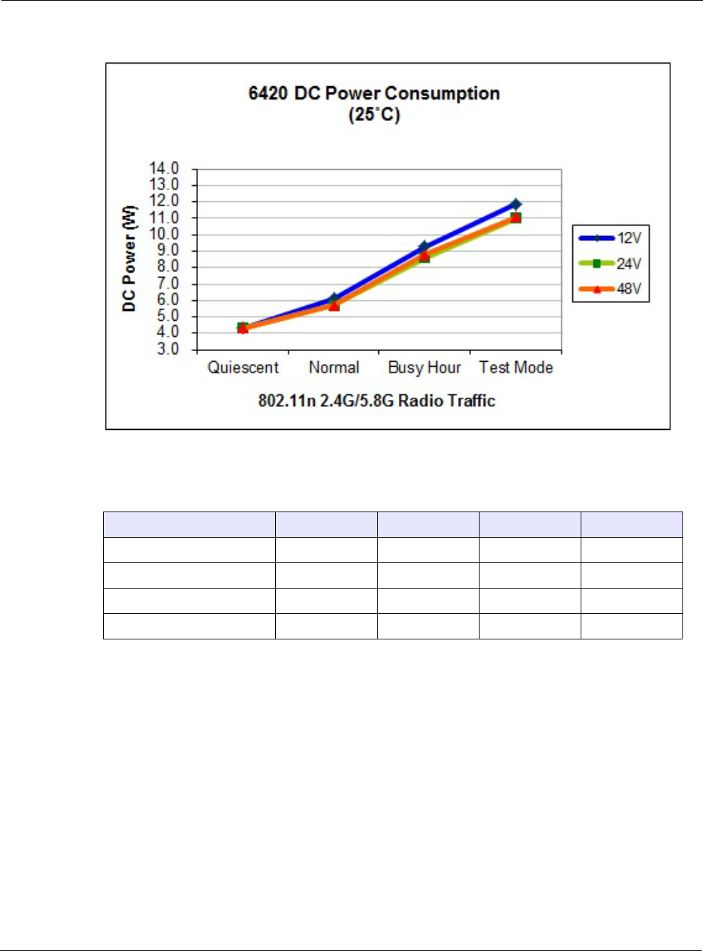
The figures and tables in this chapter show router power consumption as a function of traffic
load.
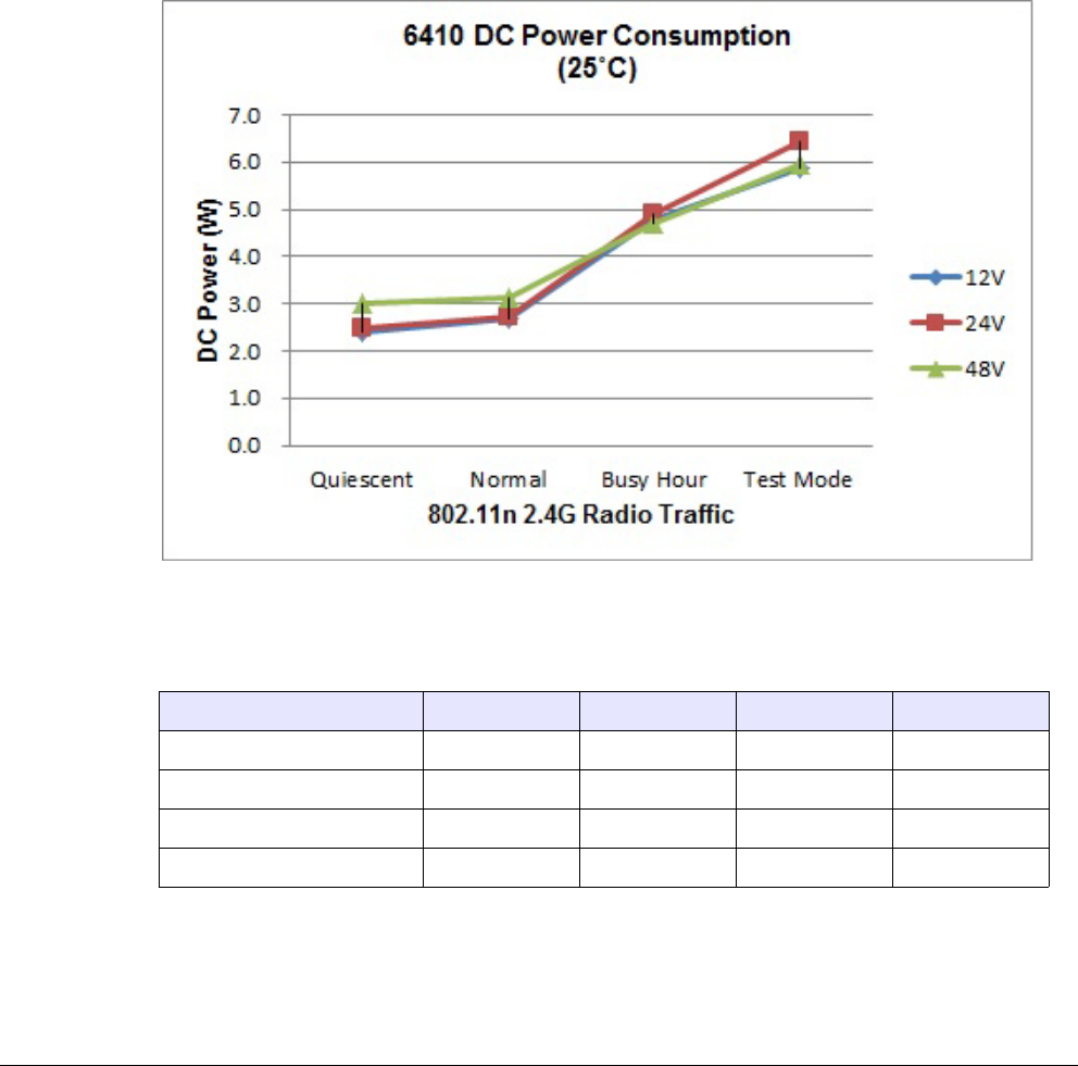
FIGURE 21 6410 Power Consumption
TABLE 8 6410 Power Consumption (Watts) at Specified Input Voltage
Traffic level Duty cycle 12V 24V 48V
Quiescent (beacon only) 0% 2.4 2.5 3.0
Normal 10% 2.7 2.7 3.1
Busy hour 30% 4.8 4.9 4.7
Maximum 50% 5.9 6.5 6.0
Chapter 4
Tropos Routers Installation Guide, Models 6410 and 6420 49
FIGURE 22 6420 Power Consumption
TABLE 9 6420 Power Consumption (Watts) at Specified Input Voltage
Traffic level Duty cycle 12V 24V 48V
Quiescent (beacon only) 0% 4.3 4.3 4.3
Normal 10% 6.1 5.7 5.7
Busy hour 30% 9.3 8.6 8.8
Maximum 50% 11.9 11.0 11.1

Tropos Routers Installation Guide, Models 6410 and 6420 50
5Product Specifications
The tables in this chapter contain specifications for the Tropos 6410 and 6420 routers:
“Physical Specifications” on page 50
“Interfaces” on page 52
“Power Options / Consumption” on page 54
“Certifications, Other” on page 54
“PS079001 - Outdoor PoE Injector, non-photocell” on page 55
“BB063001 - External Battery Backup Unit” on page 55
TABLE 10 Physical Specifications
Specification Value
Physical Dimensions
Inches Height: 2.5" (6.4cm) without antennas
Height: 14.25" (36.2cm) with antennas
Width: 8.75" (22.2cm)
Depth: 7.25" (18.4cm)
Weight
lbs - maximum
kg - maximum
4 lbs (1.8 kg)
5 lbs (2.3 kg) with mounting brackets
Mounting
Mounting Pole Diameter 1” to 10”
Mounting Hole Dimensions 6 1/8” by 4”
Temperature
Operating Range Min: -40o C
Max: 55o C
Storage Range Min: -40o C
Max: 85o C
Weather
Weather Rating IP67 weathertight
Wind Survivability > 165 mph

Chapter 5
Tropos Routers Installation Guide, Models 6410 and 6420 51
Wind Loading (165 mph) < 210 newtons
Projected Area 0.7 sq. ft. (100 sq. in.)
Corrosion Resistance ASTM B117 salt fog rust resistance compliant
Color
Color Unpainted metal/gray radome
Shock and Vibration
Operational: ETSI 300-19-2-4 specification T4.1E, class 4M3
Transportation: ISTA 2A
Status Lamp
Indicators Green/Red/Blue
TABLE 10 Physical Specifications (continued)
Specification Value

Chapter 5
Tropos Routers Installation Guide, Models 6410 and 6420 52
TABLE 11 Interfaces
Specification Value
LAN Interface
IEEE 802.3
10/100/1000 BaseT
•Auto sensing
•Maximum Distance (ft):
330 (10BaseT Duplex Setting)
330 (100BaseT Duplex Setting)
330 (1000BaseT Duplex Setting)
•RJ45 connector
MGT Interface
IEEE 802.3 10/100Base T •Auto sensing
•Maximum Distance (ft):
330 (10BaseT Duplex Setting)
330 (100BaseT Duplex Setting)
•RJ45 connector
802.11b/g/n Wireless Interface
Standard IEEE 802.11b/g/n Wi-Fi
Frequency Range •2400 to 2483 MHz ISM Band (CH 1-11) FCC Part 15
Models: 641030X0, 642030X0
•2400 to 2500 MHz (CH 1-13) ETSI/EU
Models: 641030X2, 642030X2
Modulation 802.11g/n - OFDM (64-QAM, 16-QAM, QPSK, BPSK)
802.11b - DSSS (DBPSK, DQPSK, CCK)
Rx Sensitivity
Tx Power ETSI/EU 5dBm-20dBm (EIRP) set in 1dB units
FCC/IC 20dBm-36dBm (EIRP) set in 1dB units
-97dBm @ 1 Mbps -95dBm @ 18 Mbps
-94dBm @ 5.5 Mbps -92dBm @ 24 Mbps
-92dBm @ 11 Mbps -89dBm @ 36 Mbps
-96dBm @ 6 Mbps -85dBm @ 48 Mbps
-96dBm @ 12 Mbps -84dBm @ 54 Mbps

Chapter 5
Tropos Routers Installation Guide, Models 6410 and 6420 53
Rx Saturation
Maximum Power at Antenna
Port
-5dBm (1 Mbps)
-5dBm (2 Mbps)
-5dBm (5.5 Mbps)
-5dBm (11 Mbps)
-5dBm (6 Mbps)
-5dBm (9 Mbps)
-5dBm (12 Mbps)
-10dBm (18 Mbps)
-30dBm (24 Mbps)
-35dBm (36 Mbps)
-35dBm (48 Mbps)
-35dBm (54 Mbps)
Antennas Multi-antenna system: 2 TX x 2 RX (2x2 MIMO)
7.5dBi omnidirectional integrated antennas
802.11a/n Wireless Interface
Standard IEEE 802.11a/n Wi-Fi
Frequency Range 5.725 - 5.850 GHz (FCC/IC)
5.470 - 5.725 GHz (ETSI/EU)
Modulation OFDM (64-QAM, 16-QAM)
Rx Sensitivity
Tx Power ETSI/EU 15dBm-30dBm (EIRP) set in 1dB units
FCC/IC 19dBm-36dBm (EIRP) set in 1dB units
Rx Saturation
Maximum Power at Antenna
Port
-30dBm (6 Mbps)
-30dBm (9 Mbps)
-30dBm (12 Mbps)
-30dBm (18 Mbps)
-30dBm (24 Mbps)
-35dBm (36 Mbps)
-35dBm (48 Mbps)
-35dBm (54 Mbps)
Antennas Multi-antenna system: 2 TX x 2 RX (2x2 MIMO)
8dBi omnidirectional integrated antennas
TABLE 11 Interfaces (continued)
Specification Value
-92dBm @ 6 Mbps -84dBm @ 24 Mbps
-91dBm @ 9 Mbps -81dBm @ 36 Mbps
-90dBm @ 12 Mbps -77dBm @ 48 Mbps
-87dBm @ 18 Mbps -75dBm @ 54 Mbps
Chapter 5
Tropos Routers Installation Guide, Models 6410 and 6420 54
TABLE 12 Power Options / Consumption
Specification Value
Antenna Protection <= 0.5μJ for 3kA @ 8/20μS Waveform
EN61000-4-2 Level 4 ESD Immunity
EN61000-4-5 Level 4 Surge Immunity
Data Port Protection EN61000-4-2 Level 4 ESD Immunity
EN61000-4-5 Level 4 Surge Immunity
Power Input 802.3at (LAN port)
11-55 VDC (MGT Port)
Power Consumption 10 W typical
TABLE 13 Certifications, Other
Regulatory Domain Specification
U.S. CFR 47 FCC Part 15.C; Class B
UL579/IEC 60529 IP67 Rated for Outdoor Use
ISTA 2A
Europe EN60950 cTUVus Listed I.T.E.
IEEE/ANSI C62.41 Category C AC Surge Immunity
EN61000-4-5 Level 4 AC Surge Immunity
EN61000-4-2 Level 4 ESD Immunity
EN61000-4-4 Level 4 EFT Burst Immunity
EN61000-4-3 EMC Field Immunity
ETSI EN 301 489-17
ETSI EN 300 328
EN 60950-1, IEC 60950-1
CISPR 22 Class B
CE
Canada Industry Canada RSS210

Chapter 5
Tropos Routers Installation Guide, Models 6410 and 6420 55
TABLE 14 PS079001 - Outdoor PoE Injector, non-photocell
Specification Value
Input voltage 120-240VAC 50/60Hz
Output voltage 48VDC
Data input / output 10/100Base-T
Connector 3 x RJ45
Dimensions height: 4.92" / 125mm
width: 6.77" / 172mm
depth: 2.36" / 60mm
Weight 2.5 lbs. / 1.1 kg
Operating temperature -40oF to +158oF /
-40oC to +70oC
Storage temperature -40oF to +185oF /
-40oC to +85oC
Weather rating IP54 / NEMA4x
Wind loading <300 Newtons @ 165MPH / 264kmph
Wind survivability 165MPH / 264kmph
TABLE 15 BB063001 - External Battery Backup Unit
Specification Value
Input voltage 48VDC
Output voltage 24VDC
Data input / output 10/100Base-T
Connector 3 x RJ45
Dimensions height: 4.92" / 125mm
width: 6.77" / 172mm
depth: 2.36" / 60mm
Weight 2.5 lbs. / 1.1 kg
Battery type Lithium ion
Battery voltage 24VDC
Battery capacity 62.4 Watt-hours (2.6A-hour)

Chapter 5
Tropos Routers Installation Guide, Models 6410 and 6420 56
6410/6420 operation on
battery backup 4 to 6 hours at 20oC
Operating temperature -40oF to +140oF / -40oC to +60oC
Storage temperature -40oF to +185oF / -40oC to +85oC
Charging temperature -40oF to +113oF / -40oC to +45oC
Weather loading IP54 / NEMA4x
Wind loading <300 Newtons @ 165MPH / 264kmph
Wind survivability 165MPH / 264kmph
TABLE 15 BB063001 - External Battery Backup Unit (continued)
Specification Value

Chapter 6
Tropos Routers Installation Guide, Models 6410 and 6420 58
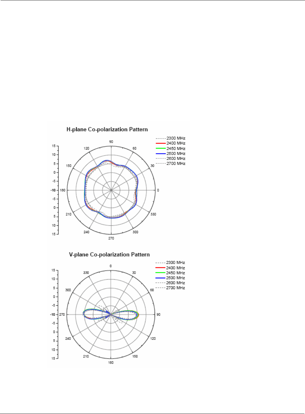
2.4 GHz Antennas
Specifications for the 2.4 GHz antennas:
Integrated omni antenna
Length: 11.5” (29.2 cm)
Average gain azimuth: 5.2dBi
Gain: 7.5 dBi
Maximum efficiency: 79%
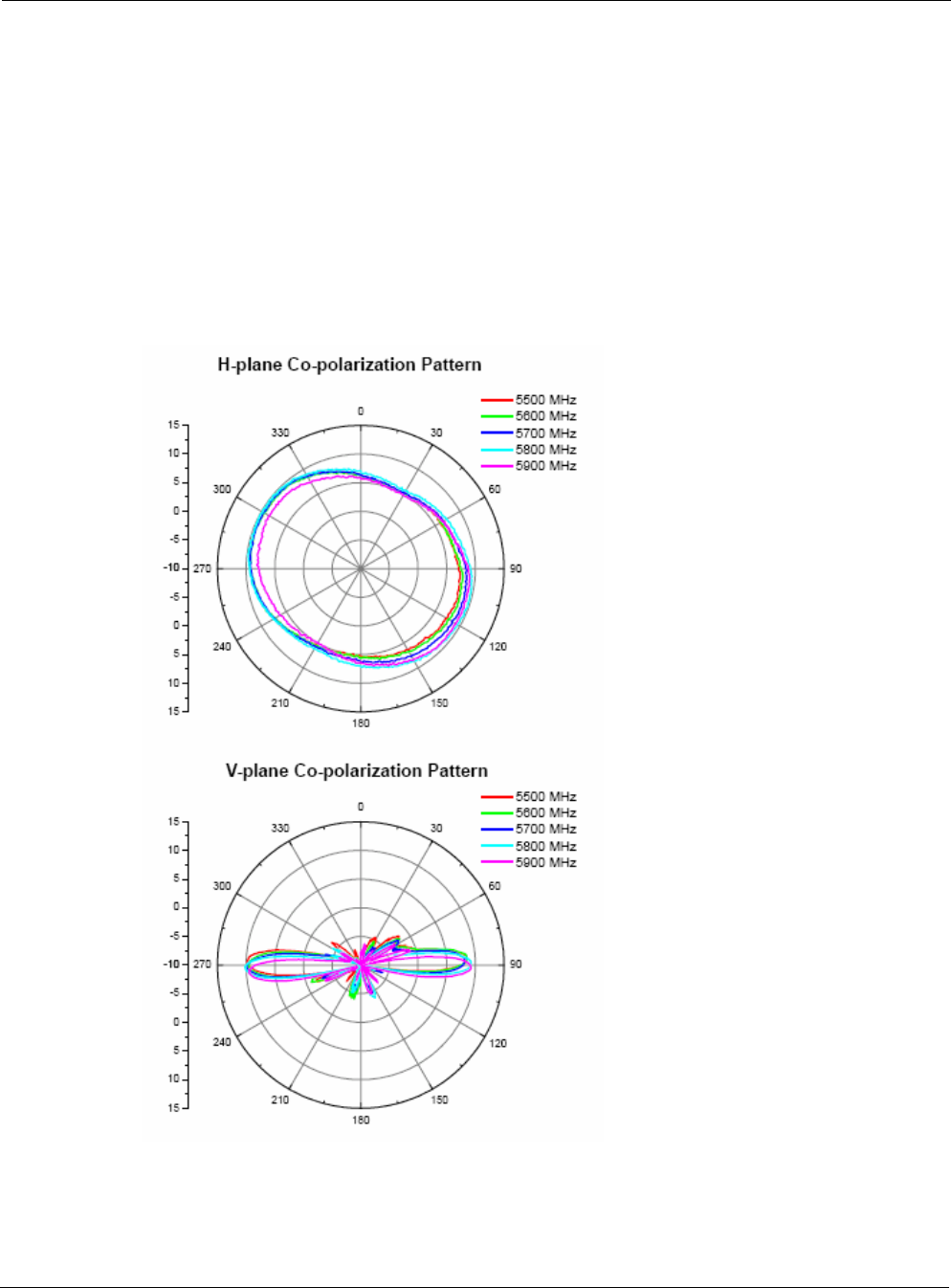
Antenna Patterns are shown in Figure 23.
FIGURE 23 2.4 GHz Antenna Patterns

Tropos Routers Installation Guide, Models 6410 and 6420 60
Abbreviations
The following abbreviations are used in this document.
TABLE 16 Abbreviations
2P Two-Phase or Split Phase
2W Two-Wire
3W Three-Wire
AASHTO American Association of State Highway and Transportation Officials
AC Alternating Current
ANSI American National Standards Institute
AWG American Wire Gauge
BBU Battery Backup Unit
C Celsius
CAT Category
CCK Complementary Code Keying
CE Conformite Europeene
CFR Code of Federal Regulations
CISPR International Special Committee on Radio Interference
CSA Canadian Standard Association
dB Decibels
dBi Decibels Relative to an Isotropic Radiator
dBm Decibels Referred to 1 Milliwatt
DBPSK Differential-Binary Phase-Shift Keying

Tropos Routers Installation Guide, Models 6410 and 6420 61
DC Direct Current
DGT Directorate General of Telecommunications (Taiwan)
DQPSK Differential-Quadrature Phase-Shift Keying
DSSS Direct-Sequence Spread Spectrum
EFT Electrically Fast Transients
EIRP Effective Isotropic Radiated Power
EMC Electromagnetic Compatibility
EN IEC standard
ESD Electrostatic Discharge
ETSI European Telecommunications Standards Institute
EU European Union
FCC Federal Communications Commission
FHSS Frequency Hopping Spread Spectrum
HFC Hybrid Fiber Coax
Hz Hertz
IEC International Electrotechnical Commission
IEEE Institute of Electrical and Electronics Engineers
IP67 Ingress Protection Standard
ISM Instrumentation, Scientific, and Medical band
ISTA International Safe Transit Association
LAN Local Area Network
Mbps Megabits Per Second
MHz Megahertz
MIL-STD Military Standard
MPHPT Ministry of Public Management, Home Affairs, Posts and Telecommunications (Japan)
MSO Multiple Service Operator
MTBF Mean Time Between Failure
TABLE 16 Abbreviations (continued)

Tropos Routers Installation Guide, Models 6410 and 6420 62
N Neutral
NEC National Electrical Codes
NEMA National Electrical Manufacturers Association
OFDM Orthogonal Frequency Division Multiplexing
P Phase
PE Protective Earth
PoE Power over Ethernet
RJ45 Registered Jack 45
RSS Received Signal Strength
Rx Receive
RXD Receive Data
TUV Technical Inspection Association
Tx Transmit
TXD Transmit Data
UL Underwriters Laboratories
UPS Uninterruptible Power Supply
VAC Voltage (Alternating Current)
VCCI Voluntary Control Council for Interference (Japan)
VDC Voltage (Direct Current)
VSWR Voltage Standing Wave Ratio
WWatts
TABLE 16 Abbreviations (continued)

Tropos Routers Installation Guide, Models 6410 and 6420 63
Index
Numerics
2.4 GHz antenna 58
2.4 GHz antennas 58
5 GHz antenna 59
6410 router 11
6420 router 12
A
AC
wiring diagrams 44
antennas
2.4 GHz 58
5 GHz 59
general information and restrictions 3
patterns 58, 59
type and placement 17
B
battery backup unit (BBU) 38
building materials 17
C
cable gland 30
cautions 6
clamps 19
clearance for mounting 18
concrete pole mounting 20
connecting a data port 29
D
data cables
attaching before mounting 18
data port
connecting 29
data protection device 35
data rate considerations 17
distance limits 16
E
external battery backup Unit BB063001 38
F
FCC antenna rules 14
G
grounding
connecting 35
data protection device 35
router 34
I
installation hardware and tools 16
installation, site surveys 17
installing Tropos router 11, 14
interfaces 52
L
location guidelines 17
M
metal pole mounting 21
models 11
mounting
clearance 18
instructions 20
large diameter poles 19
metal pole 21
orientation 18
strategies 18
streetlight 28
streetlight options 18
to wood, concrete, painted poles 20
tower 27
wood brace 26
wood pole 24
O
obstructions 17
Outdoor PoE Injector, non-photocell PS079001 38
P
physical environment 17
PoE injector
non-photocell (PS079001) 38
pole mounting 21
power
consumption 48
specifications 54
preparing for installation 14
product specifications
interfaces 52
physical 50
power 54
R
regulatory notices 2
router
diagram 15

Tropos Routers Installation Guide, Models 6410 and 6420 64
exploded view 15
router models 11
rubber boot 30
S
safety
general considerations 17
information 36
site planning 16
site surveys 17
specifications
interfaces 52
physical 50
power 54
streetlight
mounting instructions 28
mounting options 18
T
tools for installation 16
tower mounting 27
W
warnings, general 5
wood brace mounting 26
wood pole mounting 24