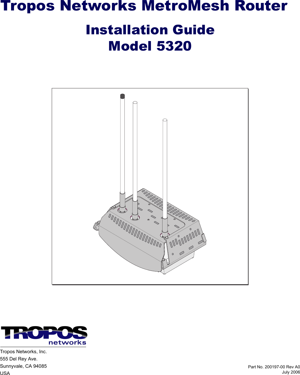
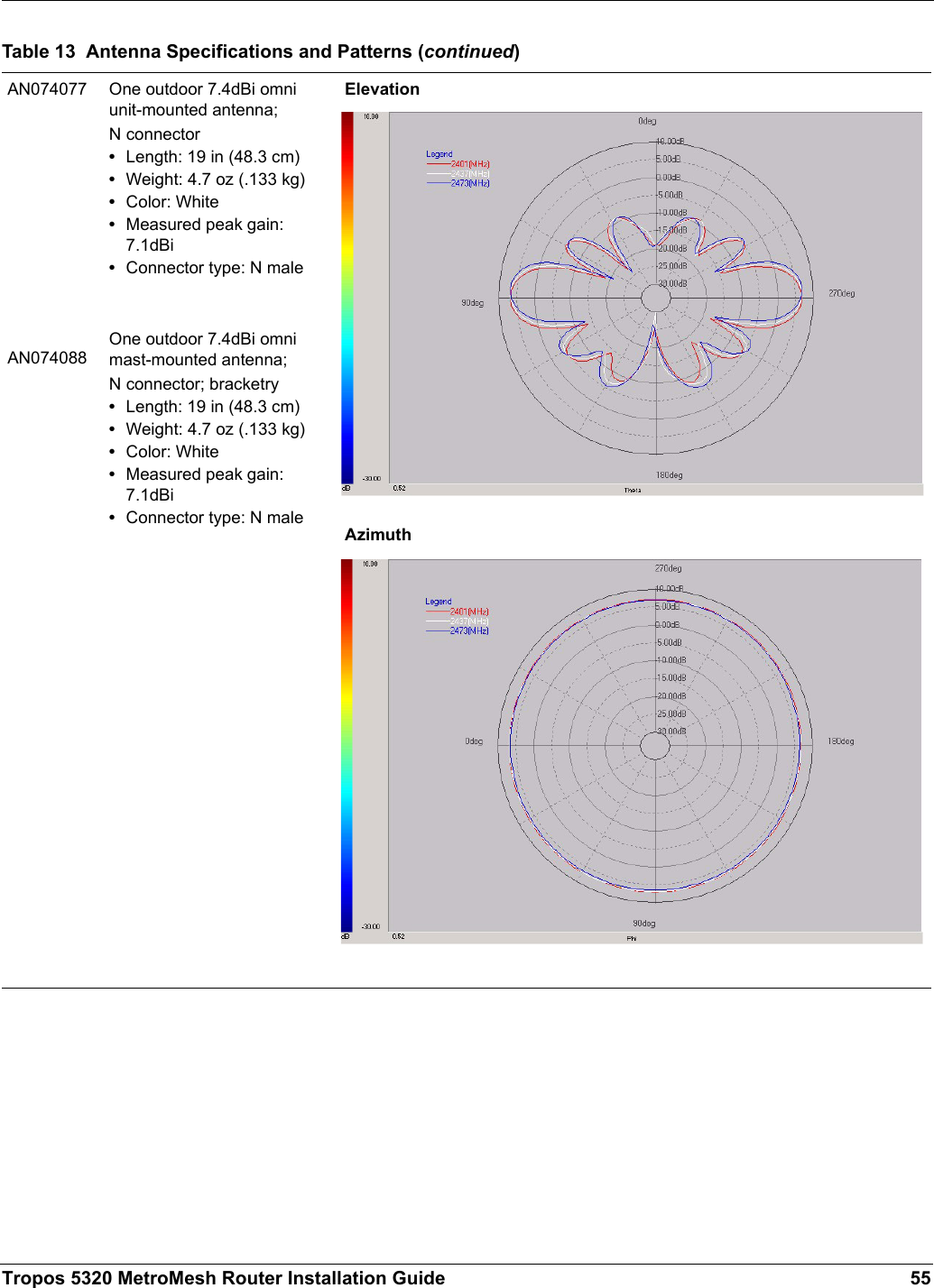
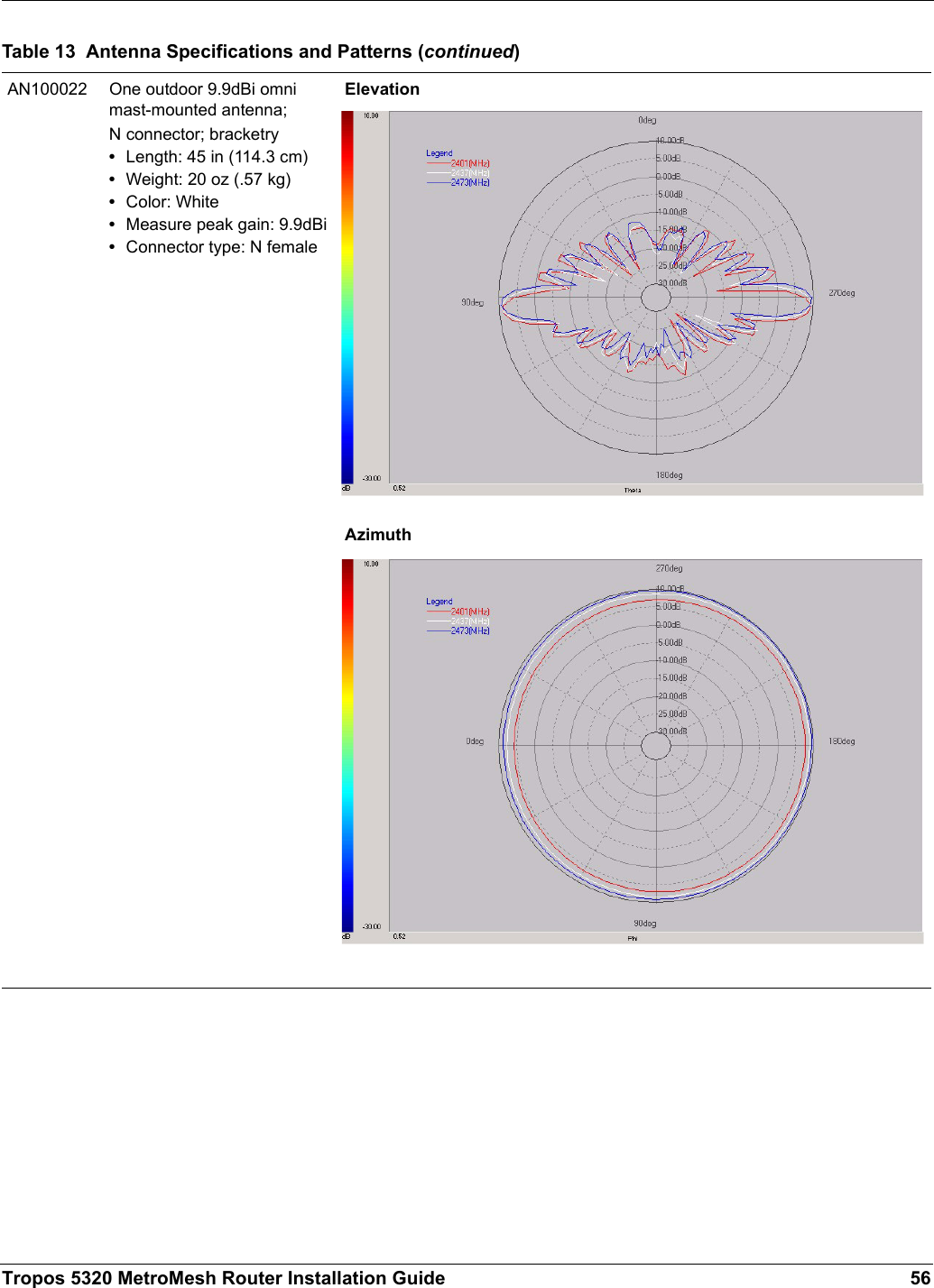
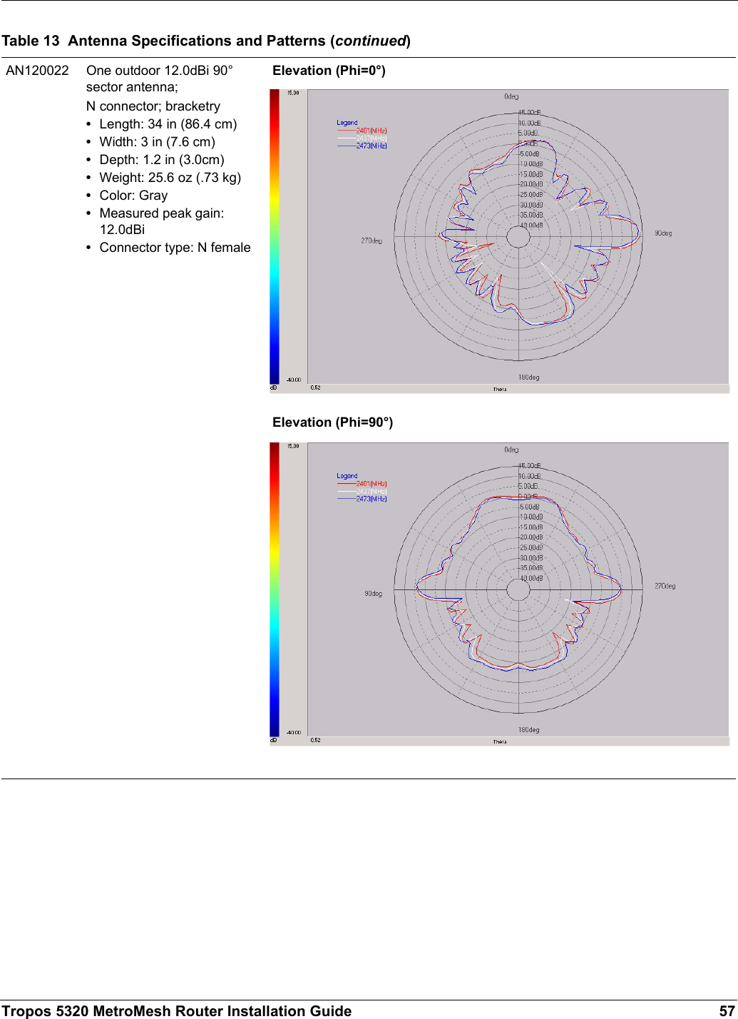
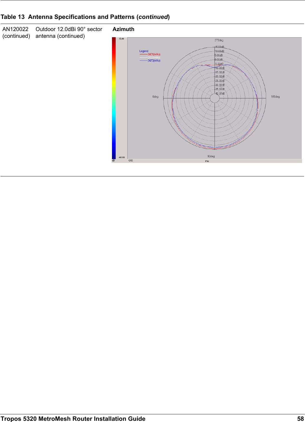
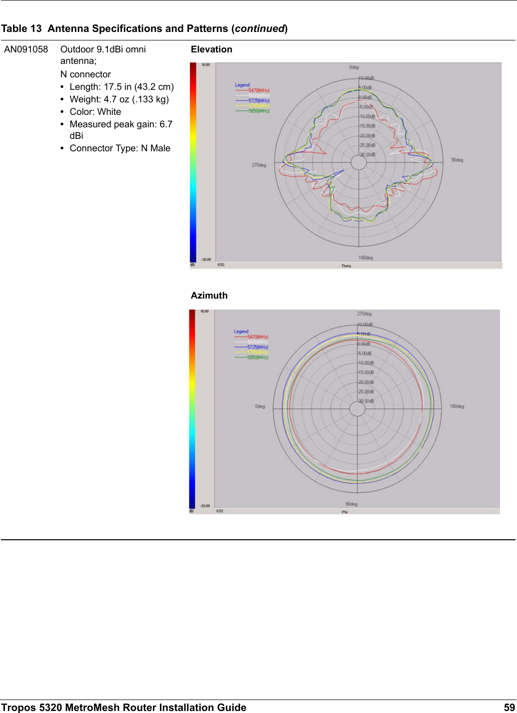
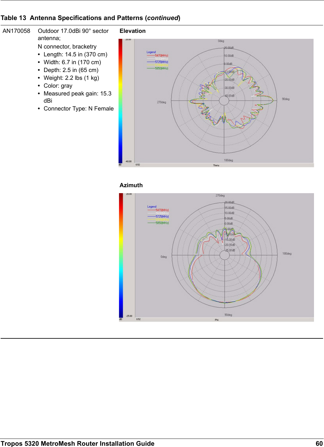
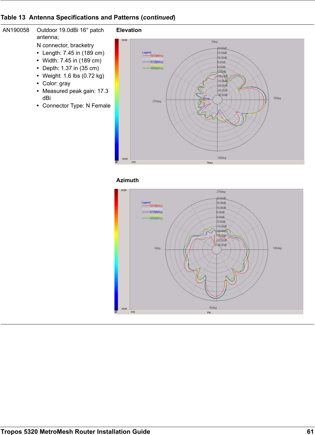
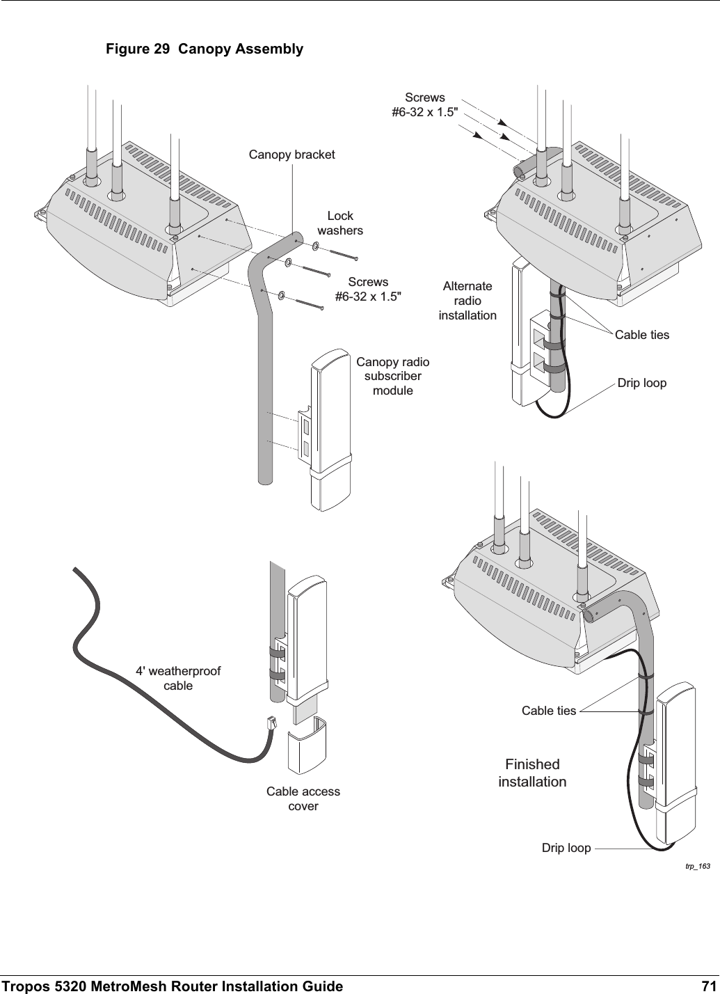
ABB Enterprise Software BFD 802.11 a/b/g Module User Manual 5320 Guide
Tropos Networks, Inc. 802.11 a/b/g Module 5320 Guide
UserManual.wiki
>
ABB Enterprise Software
>
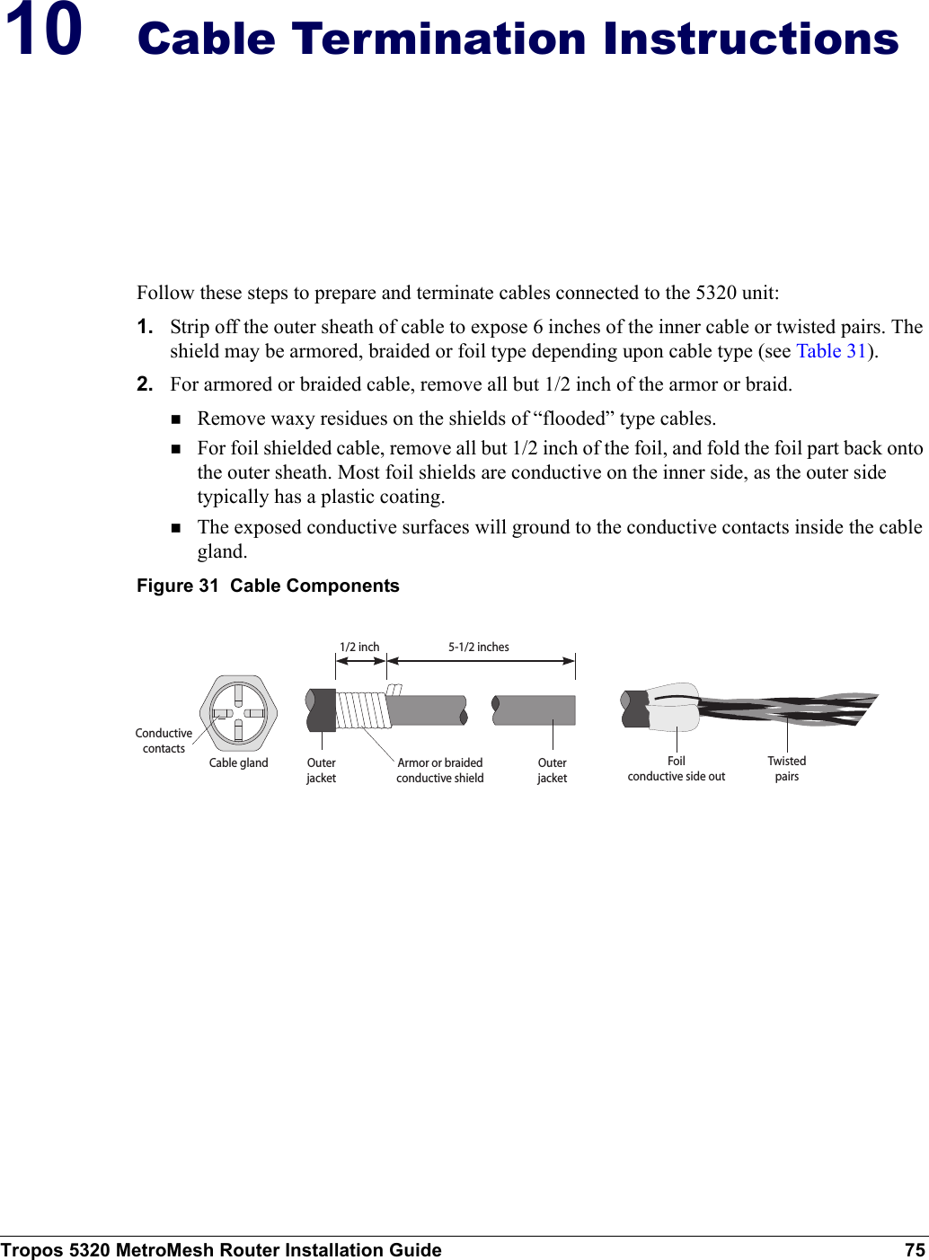
BFD User Manual
Users Manual
Navigation menu
Upload a User Manual
Namespaces
Wiki Guide
HTML
PDF
Info
Views
User Manual
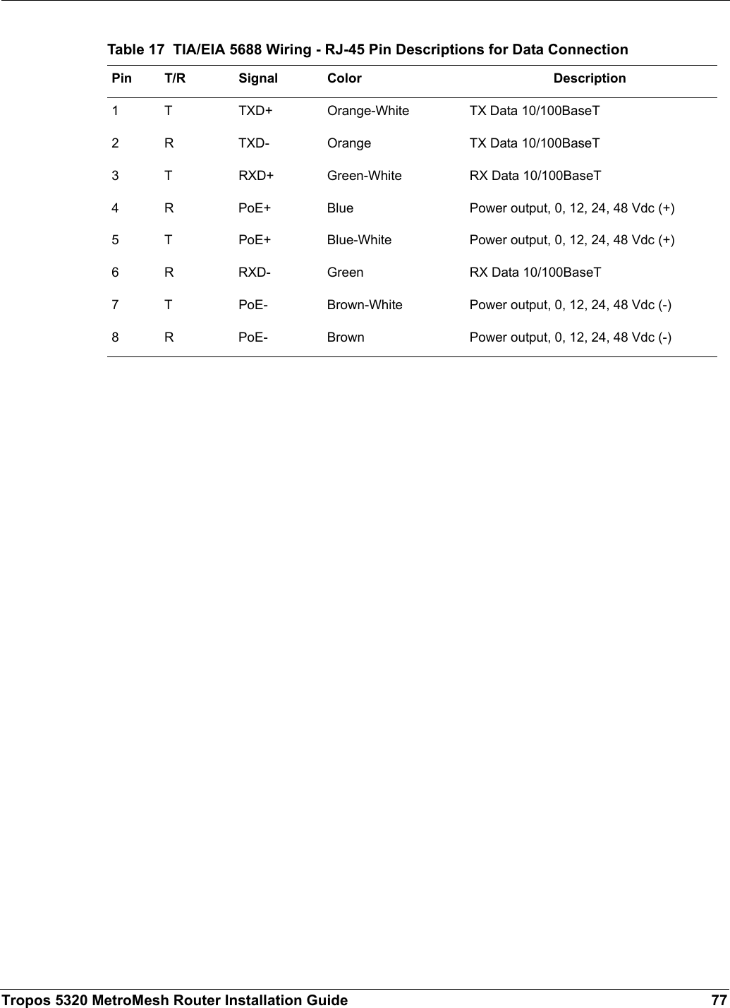
Discussion / Help
Navigation