ABB Enterprise Software BFD 802.11 a/b/g Module User Manual 5320 Guide
Tropos Networks, Inc. 802.11 a/b/g Module 5320 Guide
Users Manual
Part No. 200197-00 Rev A0
July 2006
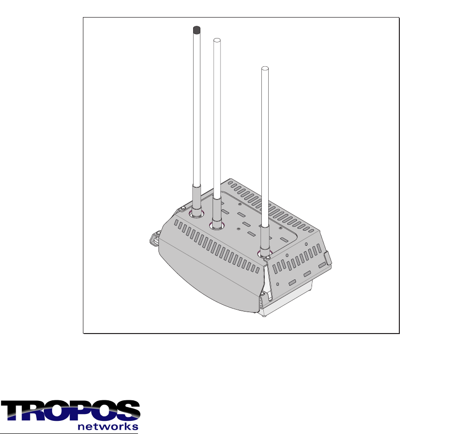
Tropos Networks MetroMesh Router
Installation Guide
Model 5320
Tropos Networks, Inc.
555 Del Rey Ave.
Sunnyvale, CA 94085
USA

Tropos 5320 MetroMesh Router Installation Guide ii
Copyright Notice
©2006 Tropos Networks, Inc. All rights reserved. Tropos Networks is a registered trademark of
Tropos Networks, Inc. in the United States and certain other jurisdictions. Specifications are
subject to change without notice.
Loctite is a registered trademark of Loctite Corporation, USA.
This product includes technology protected by U.S. Patents 6,704,301; 6,965,575; 7,016,328,
and 7,031,293.
FCC Notice to Users and Operators
This device complies with Part 15 of the FCC Rules. Operation is subject to the following two
conditions: (1) this device may not cause harmful interference, and (2) this device must accept
any interference received, including interference that may cause undesired operation.
This equipment has been tested and found to comply with the limits for a Class B digital device,
pursuant to Part 15 of the FCC Rules. These limits are designed to provide reasonable protection
against harmful interference when the equipment is operated in a commercial environment. This
equipment generates, uses, and can radiate radio frequency energy and, if not installed and used
in accordance with the instruction manual, may cause harmful interference to radio
communications. Operation of this equipment in a residential area is likely to cause harmful
interference, in which case the user will be required to correct the interference at his own
expense. If this equipment does cause interference to radio or television reception, which can be
determined by turning the equipment off and on, the user is encouraged to correct the
interference by using one of the following measures:
Reorient or relocate the receiving antenna.
Increase separation between the equipment and receiver.
Connect the equipment to an outlet on a circuit different from that to which the receiver is
connected.
Consult the dealer or an experienced radio/TV technician.
This Part 15 radio device operates on a non-interference basis with other devices operating at
this frequency. Any changes or modification to said product not expressly approved by Tropos
Networks could void the user's authority to operate this device.
Industry Canada
Notice to users and operators:
This Class B digital apparatus meets all requirements of the Canadian Interference Causing
Equipment Regulations. Operation is subject to the following two conditions: (1) this device
may not cause harmful interference, and (2) this device must accept any interference received,
including interference that may cause undesired operation.
Tropos 5320 MetroMesh Router Installation Guide iii
Cet appareillage numérique de la classe B répond à toutes les exigences de l’interférence
canadienne causant des réglements d’équipement. L’opération est sujette aux deux conditions
suivantes : (1) cet dispositif peut ne pas causer l'interférence nocive, et (2) ce dispositif doit
accepter n’importe quelle interférence reçue, y compris l'interférence qui peut causer l’opération
peu désirée.
Warning
It is illegal to modify the construction of this product. Modifying the operating frequency or
enhancing the transmit output power through the use of external amplifiers or other
equipment is specifically disallowed by the “Telecommunications Act.”
Warning
This device is for outdoor or indoor use with conditions that no harmful interference to
authorized radio stations results from the operation of this device. This device shall not
influence aircraft security and/or interfere with legal communications as defined in the
“Telecommunications Act.” If this device is found to cause interference, the operator of this
equipment shall cease operating this device immediately until no interference is achieved.
European Union WEEE Notice
It is important for users of this equipment to participate in reuse, recycling, and other forms of
recovery. The potential effects on the environment and human health as a result of the presence
of hazardous substances in electrical and electronic equipment are a waste of natural resources
and cause pollution.
For EU member countries, this symbol means: Do not dispose of this equipment
as unsorted municipal waste. This equipment must be collected separately.
The return and collection of this product has not been defined at this time, please
contact Tropos Networks for return and/or collection.
Tropos 5320 MetroMesh Router Installation Guide iv
European Community Language Versions of Informal
Statement for Inclusion in User Information
The following statements are in accordance with Article 6.3 of Directive 1999/5/EC.
Tropos 5320 MetroMesh Router Installation Guide v
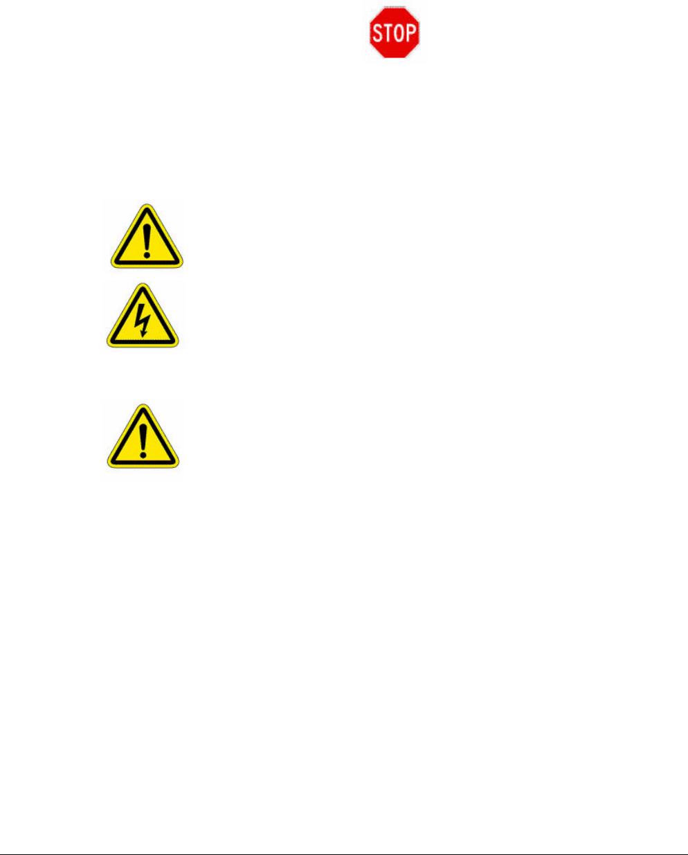
STOP!! STOP!! STOP!! STOP!!
READ THIS FIRST!
Important Safety Instructions
The exclamation point within an equilateral triangle is intended to alert the user
to the presence of important operating and maintenance (servicing) instructions
in the literature accompanying the product.
The lightning flash with an arrowhead symbol within an equilateral triangle is
intended to alert the user to the presence of uninsulated “dangerous voltage”
within the product’s enclosure that may be of sufficient magnitude to constitute a
risk of electric shock to persons.
Caution
Read these instructions.
Keep these instructions.
Heed all warnings.
Follow all instructions.
Do not defeat the safety purpose of the grounding.
Only use attachments/accessories specified by the manufacturer.
Refer all servicing to qualified service personnel. Servicing is required when the
apparatus has been damage in any way, such as power-supply cord or plug is
damaged, liquid has been spilled on objects have fallen into the apparatus, the
apparatus has been exposed to rain or moisture, does not operate normally, or has
been dropped.
Tropos 5320 MetroMesh Router Installation Guide vi
Warning
Risk of personal injury or death when installing this device!
There is a risk of personal injury or death if the router antennas come near
electric power lines. Carefully read and follow all instructions in this manual. By
nature of the installation, you may be exposed to hazardous environments and
high voltage. Use caution when installing the outdoor system.
This apparatus must be connected to earth ground.
Do not open the unit — risk of electric shock inside.
Risque d'électrocution. Ne pas ouvrir l'unité.
Caution
You are cautioned that any change or modification not expressly approved in this
manual could void your authority to operate this equipment.
Les changements et modifications, non expressément approuvés dans le présent
manuel, peuvent entraîner une interdiction d'utiliser cet appareil pour l'utilisateur.
Service
There are no user-serviceable parts inside. All service must be performed by
qualified personnel.
Vous ne devez pas réparer les pièces se trouvant à l'intérieur de l'appareil. Les
réparations doivent être effectuées uniquement par du personnel qualifié.
The Tropos 5320 MetroMesh Router may contain a lithium-ion battery. To avoid
the possibility of an explosion, the Tropos 5320 MetroMesh Router should NOT
be exposed to any temperatures higher than 85 degrees C.
The RJ45 connectors of your Tropos 5320 MetroMesh Router may source DC
power on pins 4,5 and 7,8. The IEEE 802.3 standards allow for pins 4,5 and 7,8
to be used for Power Over Ethernet. Some products may be incompatible with the
Tropos Power Over Ethernet capability. If such problems occur, make sure that
the unit is configured with the Power Over Ethernet capability set to Off (default
setting). If problems persist, use Ethernet cables that have no connections to the
unused pins 4,5 and 7,8.
Tropos 5320 MetroMesh Router Installation Guide vii
The Tropos 5320 MetroMesh Router is installed in wet, outdoor locations. Make
sure closure caps are installed and all cable connections are securely fastened and
waterproofed.
The Tropos 5320 MetroMesh Router can only be used with approved antennas.
See Appendix C, “Approved Antenna Configurations and Attenuation Settings”
for further information.
Surfaces may become hot. Use caution when accessing the Tropos 5320
MetroMesh router.

Tropos 5320 MetroMesh Router Installation Guide viii
Contents
1 Installing the Tropos MetroMesh Router . . . . . . . . . . . . . . . . . . . . . . . . . 1
Preparing for Installation . . . . . . . . . . . . . . . . . . . . . . . . . . . . . . . . . . . . . 2
Model Numbers . . . . . . . . . . . . . . . . . . . . . . . . . . . . . . . . . . . . . . . . . 2
Installation Hardware and Tools . . . . . . . . . . . . . . . . . . . . . . . . . . . . . 4
Site Planning . . . . . . . . . . . . . . . . . . . . . . . . . . . . . . . . . . . . . . . . . . . . 4
Location Guidelines . . . . . . . . . . . . . . . . . . . . . . . . . . . . . . . . . . . . . . 5
Antenna Options . . . . . . . . . . . . . . . . . . . . . . . . . . . . . . . . . . . . . . . . . 5
Site Surveys . . . . . . . . . . . . . . . . . . . . . . . . . . . . . . . . . . . . . . . . . . . . 5
Power Source . . . . . . . . . . . . . . . . . . . . . . . . . . . . . . . . . . . . . . . . . . . 6
Safety . . . . . . . . . . . . . . . . . . . . . . . . . . . . . . . . . . . . . . . . . . . . . . . . . 6
Mounting Strategies . . . . . . . . . . . . . . . . . . . . . . . . . . . . . . . . . . . . . . . . . 7
Proper Use of Hose Clamps. . . . . . . . . . . . . . . . . . . . . . . . . . . . . . . . . . . 8
Pole, Tower, and Streetlight Mounting Instructions . . . . . . . . . . . . . . . . . 9
Metal Pole Mounting . . . . . . . . . . . . . . . . . . . . . . . . . . . . . . . . . . . . . 10
Wood Pole Mounting . . . . . . . . . . . . . . . . . . . . . . . . . . . . . . . . . . . . 13
Wood Brace Mounting . . . . . . . . . . . . . . . . . . . . . . . . . . . . . . . . . . . 14
Tower Mounting . . . . . . . . . . . . . . . . . . . . . . . . . . . . . . . . . . . . . . . . 16
Streetlight Mounting . . . . . . . . . . . . . . . . . . . . . . . . . . . . . . . . . . . . . 17
Connecting Cable Attached Antennas . . . . . . . . . . . . . . . . . . . . . . . . . . 18
Waterproofing Antenna Connections . . . . . . . . . . . . . . . . . . . . . . . . 20
Installing Attached Antennas . . . . . . . . . . . . . . . . . . . . . . . . . . . . . . 21
Grounding the Tropos 5320 Router . . . . . . . . . . . . . . . . . . . . . . . . . . . . 21
Grounding the Data Protection Device . . . . . . . . . . . . . . . . . . . . . . . 23
Connecting Power . . . . . . . . . . . . . . . . . . . . . . . . . . . . . . . . . . . . . . . . . 24
Categories of Power . . . . . . . . . . . . . . . . . . . . . . . . . . . . . . . . . . . . . 24
Connecting to AC Power (Category C) . . . . . . . . . . . . . . . . . . . . . . . 27
Connecting to Streetlight Power (Category C) . . . . . . . . . . . . . . . . . 28
Connecting a Data Port . . . . . . . . . . . . . . . . . . . . . . . . . . . . . . . . . . . . . 29
Resetting the Router . . . . . . . . . . . . . . . . . . . . . . . . . . . . . . . . . . . . . . . 34
Connecting Peripherals . . . . . . . . . . . . . . . . . . . . . . . . . . . . . . . . . . . . . 35
Battery Backup Operation . . . . . . . . . . . . . . . . . . . . . . . . . . . . . . . . . . . 37
Safety Information for the Tropos MetroMesh Router . . . . . . . . . . . . . . 38

Tropos 5320 MetroMesh Router Installation Guide ix
2 Power Consumption . . . . . . . . . . . . . . . . . . . . . . . . . . . . . . . . . . . . . . . . . 40
3 Product Specifications . . . . . . . . . . . . . . . . . . . . . . . . . . . . . . . . . . . . . . . 42
4 Approved Antenna Configurations and Attenuation Settings . . . . . . . 48
High Power Product Antennas . . . . . . . . . . . . . . . . . . . . . . . . . . . . . . . . 49
U.S. and Canada . . . . . . . . . . . . . . . . . . . . . . . . . . . . . . . . . . . . . . . 49
Standard Power Product Antennas . . . . . . . . . . . . . . . . . . . . . . . . . . . . 50
Europe . . . . . . . . . . . . . . . . . . . . . . . . . . . . . . . . . . . . . . . . . . . . . . . 50
5 Antenna Specifications and Patterns . . . . . . . . . . . . . . . . . . . . . . . . . . . 53
6 Installation Accessories . . . . . . . . . . . . . . . . . . . . . . . . . . . . . . . . . . . . . . 63
7 AC Wiring Diagrams . . . . . . . . . . . . . . . . . . . . . . . . . . . . . . . . . . . . . . . . . 66
8 Wind Loading Considerations . . . . . . . . . . . . . . . . . . . . . . . . . . . . . . . . . 69
9 Canopy Installation Instructions . . . . . . . . . . . . . . . . . . . . . . . . . . . . . . . 70
10 Cable Termination Instructions . . . . . . . . . . . . . . . . . . . . . . . . . . . . . . . . 75
Abbreviations . . . . . . . . . . . . . . . . . . . . . . . . . . . . . . . . . . . . . . . . . . . . . . 78
Index . . . . . . . . . . . . . . . . . . . . . . . . . . . . . . . . . . . . . . . . . . . . . . . . . . . . . . 81

Tropos 5320 MetroMesh Router Installation Guide x
List of Figures
Tropos MetroMesh Router Exploded View . . . . . . . . . . . . . . . . . . . . . . . 3
Example Mounting Location - Antennas Facing Upward . . . . . . . . . . . . 7
Proper Use of Hose Clamps . . . . . . . . . . . . . . . . . . . . . . . . . . . . . . . . . . 8
Metal Pole Mounting . . . . . . . . . . . . . . . . . . . . . . . . . . . . . . . . . . . . . . . 10
Sun Shield Connections . . . . . . . . . . . . . . . . . . . . . . . . . . . . . . . . . . . . 12
Wood Pole Mounting . . . . . . . . . . . . . . . . . . . . . . . . . . . . . . . . . . . . . . . 13
Wood Brace Mounting Option . . . . . . . . . . . . . . . . . . . . . . . . . . . . . . . . 14
Tower Mounting . . . . . . . . . . . . . . . . . . . . . . . . . . . . . . . . . . . . . . . . . . . 16
Streetlight Mounting . . . . . . . . . . . . . . . . . . . . . . . . . . . . . . . . . . . . . . . 17
Connecting External Antennas . . . . . . . . . . . . . . . . . . . . . . . . . . . . . . . 19
Waterproofing Antenna Connections . . . . . . . . . . . . . . . . . . . . . . . . . . 20
Grounding Arrangement . . . . . . . . . . . . . . . . . . . . . . . . . . . . . . . . . . . . 22
Grounding the Indoor Network Protection Unit . . . . . . . . . . . . . . . . . . . 23
IEEE/ANSI C62.41 Power Categories . . . . . . . . . . . . . . . . . . . . . . . . . . 26
Connecting Category C AC Power . . . . . . . . . . . . . . . . . . . . . . . . . . . . 27
Connecting the AC Power Cable . . . . . . . . . . . . . . . . . . . . . . . . . . . . . . 28
Connecting Streetlight Power . . . . . . . . . . . . . . . . . . . . . . . . . . . . . . . . 28
Options for Connecting a Data Port . . . . . . . . . . . . . . . . . . . . . . . . . . . 31
Data Cable Detail . . . . . . . . . . . . . . . . . . . . . . . . . . . . . . . . . . . . . . . . . 32
Data Port Connection . . . . . . . . . . . . . . . . . . . . . . . . . . . . . . . . . . . . . . 33
Circuit Board Connection Locations . . . . . . . . . . . . . . . . . . . . . . . . . . . 34
RJ45 Pin Locations . . . . . . . . . . . . . . . . . . . . . . . . . . . . . . . . . . . . . . . . 36
Average Battery Backup Time . . . . . . . . . . . . . . . . . . . . . . . . . . . . . . . . 37
Average Battery Backup Time vs. Temperature . . . . . . . . . . . . . . . . . . 38
AC Power Consumption vs. Throughput with PoE Output Disabled . . . 40
AC Power Consumption vs. Throughput (Battery Backup, -40o C) . . . . 41
AC Wiring — Photoelectric Power Tap . . . . . . . . . . . . . . . . . . . . . . . . . 67
AC Wiring Power Cable 120VAC, 15A Plug . . . . . . . . . . . . . . . . . . . . . 68
Canopy Assembly . . . . . . . . . . . . . . . . . . . . . . . . . . . . . . . . . . . . . . . . . 71
Cable Connections . . . . . . . . . . . . . . . . . . . . . . . . . . . . . . . . . . . . . . . . 73
Cable Components . . . . . . . . . . . . . . . . . . . . . . . . . . . . . . . . . . . . . . . . 75
Cable Gland Assembly . . . . . . . . . . . . . . . . . . . . . . . . . . . . . . . . . . . . . 76
Cable Preparation and Termination . . . . . . . . . . . . . . . . . . . . . . . . . . . 76

Tropos 5320 MetroMesh Router Installation Guide xi
List of Tables
IEEE/ANSI C62.41 Power Categories . . . . . . . . . . . . . . . . . . . . . . . . . . . . . 25
PoE Power Sourcing Power Output . . . . . . . . . . . . . . . . . . . . . . . . . . . . . . 35
RJ45 Pin Descriptions for Data Connection . . . . . . . . . . . . . . . . . . . . . . . . 36
Physical Specifications - Tropos 5320 Router . . . . . . . . . . . . . . . . . . . . . . . 42
Interfaces . . . . . . . . . . . . . . . . . . . . . . . . . . . . . . . . . . . . . . . . . . . . . . . . . . . 44
Power Options / Consumption . . . . . . . . . . . . . . . . . . . . . . . . . . . . . . . . . . . 46
Power Over Ethernet - Power Sourcing . . . . . . . . . . . . . . . . . . . . . . . . . . . 47
Certifications, Other . . . . . . . . . . . . . . . . . . . . . . . . . . . . . . . . . . . . . . . . . . . 47
802.11b/g Antenna Configurations . . . . . . . . . . . . . . . . . . . . . . . . . . . . . . . 49
802.11a Radio (5.725-5.850 GHz) - Antenna Configurations . . . . . . . . . . . 50
802.11b/g Antenna Configurations . . . . . . . . . . . . . . . . . . . . . . . . . . . . . . . 51
802.11a Radio (5.470-5.725 GHz) - Antenna Configurations . . . . . . . . . . . 51
Antenna Specifications and Patterns . . . . . . . . . . . . . . . . . . . . . . . . . . . . . 54
Installation Accessories . . . . . . . . . . . . . . . . . . . . . . . . . . . . . . . . . . . . . . . . 63
Tropos Antennas, Cables, and Related Ordering Numbers . . . . . . . . . . . . 64
Canopy Cable Wiring . . . . . . . . . . . . . . . . . . . . . . . . . . . . . . . . . . . . . . . . . 74
TIA/EIA 5688 Wiring - RJ-45 Pin Descriptions for Data Connection . . . . . . 77
Acronyms . . . . . . . . . . . . . . . . . . . . . . . . . . . . . . . . . . . . . . . . . . . . . . . . . . 78

Tropos 5320 MetroMesh Router Installation Guide 1
1Installing the Tropos MetroMesh
Router
This guide explains how to install the Tropos 5320 MetroMesh router safely and is intended for
trained technical professionals. This chapter covers the following topics:
“Preparing for Installation” on page 2
“Mounting Strategies” on page 7
“Proper Use of Hose Clamps” on page 8
“Pole, Tower, and Streetlight Mounting Instructions” on page 9
“Connecting Cable Attached Antennas” on page 18
“Connecting Cable Attached Antennas” on page 18
“Grounding the Tropos 5320 Router” on page 21
“Connecting Power” on page 24
“Connecting a Data Port” on page 29
“Resetting the Router” on page 34
“Connecting Peripherals” on page 35
“Battery Backup Operation” on page 37
“Safety Information for the Tropos MetroMesh Router” on page 38

Preparing for Installation
Tropos 5320 MetroMesh Router Installation Guide 2
Preparing for Installation
The Tropos 5320 MetroMesh router must be installed by a trained professional, value added
reseller, or systems integrator who is familiar with RF planning issues and regulatory limits
defined by the governing body of the country in which the unit will be installed. This section
lists the required equipment and model numbers and explains how to prepare the installation
site.
Model Numbers
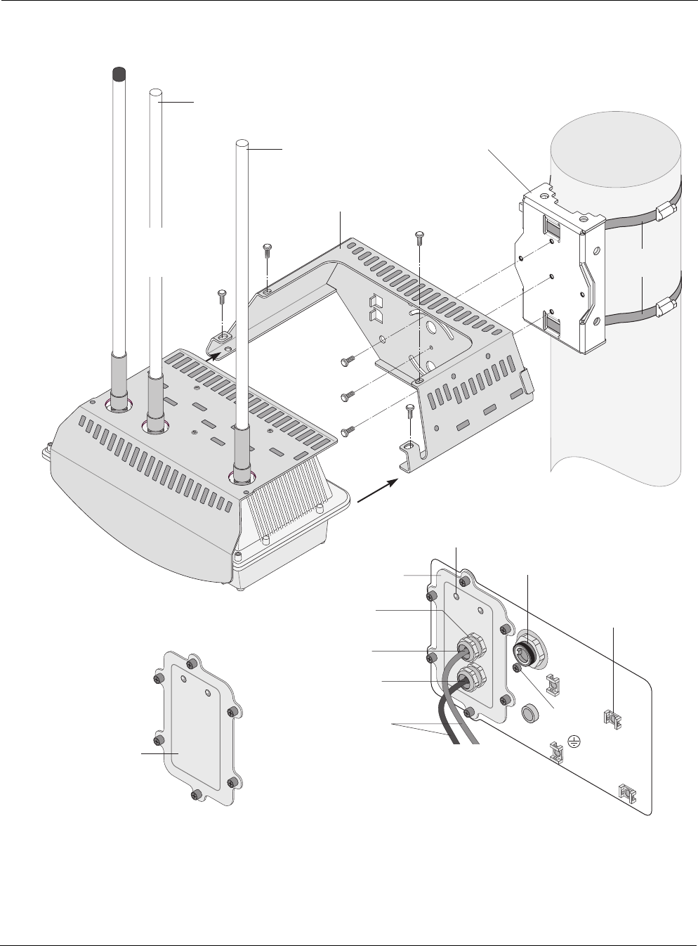
An exploded view of the Tropos 5320 MetroMesh router assembly is shown in Figure 1.
Note
Antenna(s) must be installed by a trained professional. Operating the unit with non-qualified antennas
is a violation of U.S. FCC Rules Part 15.203(c), Code of Federal Regulations, Title 47. See “Approved
Antenna Configurations and Attenuation Settings” on page 48 for a listing of antenna options.
Preparing for Installation
Tropos 5320 MetroMesh Router Installation Guide 3
Figure 1 Tropos MetroMesh Router Exploded View
trp_150
10/100 BaseT
LAN cable
#10-32
hex head 5/16"
machine screws
x5
Pole bracket
10/100 BaseT
Management cable
Shielded outdoor
cat5 cable
Cable gland
802.11b/g
Aux
Tx/Rx antenna
802.11a
Router
Sun shield
802.11b/g
Main
Tx/Rx antenna
Hose
clamps
Ground
bolt
Bottom view of Router
Connector
access cover
Connector
access cover
without
cable glands
AC input
power connector
LED
Quick tie
anchors

Preparing for Installation
Tropos 5320 MetroMesh Router Installation Guide 4
Installation Hardware and Tools
Tropos Networks provides the following accessories to install the Tropos 5320 MetroMesh
router:
One pole bracket
One sun shield
Two 4-inch diameter hose clamps
Four 6-inch diameter hose clamps
Seven 5/16-inch #10-32 stainless steel hex head machine screws
You must supply the following tools:
5/16-inch nut driver
1/4-inch flat blade screwdriver
Tower mounting only: supply stainless or galvanized steel channel stock and 1/2-inch or
5/8-inch nuts, bolts, and washers to connect to the tower arm.
Wood pole mounting only: two 5/8-inch diameter, 3-inch long lag bolts
Site Planning
To ensure safe and durable wiring, installation of the Tropos 5320 MetroMesh router must
follow appropriate electrical and building codes. Follow the National Electrical Code (NEC)
requirements, unless local codes in your area take precedence over the NEC code.
The following distance limits apply to installations that have 10/100 Base-T Category 5 network
cables attached to the Tropos 5320 MetroMesh router:
300 feet maximum between devices for 100BaseT operation
600 feet maximum for 10BaseT operation.
The Ethernet duplex and speed setting is configurable.
Note
National Electrical Codes (NEC) Article 800 requires the use of Agency Listed (UL/CSA/TUV) Building
Entrance Protector for all power and data communications cables entering a building. The NEC
intends by Article 800 to protect the building and occupants from fires caused by transient voltage and
current surges.
Note
Ethernet data cable installations having lengths greater than 140 feet in the outdoor environment must
use a UL497 approved (UL/CSA/TUV Listed) primary protection device at the building entrance.
Ethernet data cable installations having lengths less than 140 feet in the outdoor environment may use

Preparing for Installation
Tropos 5320 MetroMesh Router Installation Guide 5
a UL497A (UL/CSA/TUV Listed) secondary protection device at the building entrance. Tropos Data
Protection Device and Network Protection Units are UL497A secondary protection devices.
Location Guidelines
The Tropos 5320 MetroMesh router is a radio device and therefore susceptible to interference
that can reduce throughput and range. Follow these guidelines to ensure the best performance:
Install the unit in an area where trees, buildings, and large steel structures do not obstruct
radio signals to and from the antenna. Direct line-of-sight operation is best.
Install the unit away from microwave ovens or other devices operating in the 2.4 GHz or 5
GHz frequency range.
Install the unit away from other possible sources of 802.11a or 802.11b/g interference, such
as cordless phones, home spy cameras, frequency hopping (FHSS) and DSSS LAN
transceivers (non-802.11), electronic news gathering video links, radars, amateur radios,
land mobile radio services, local government sites (such as law enforcement), fixed
microwave services, local TV transmission and private fixed point transmitters.
Antenna Options
You can purchase the Tropos 5320 MetroMesh router with an integrated omni-directional
antenna, or use an approved external antenna. Omni-directional antennas are best for systems
requiring a signal distribution in more than one direction. To comply with regulatory RF
exposure limits, locate antennas a minimum distance of 7.9 inches (20cm) from people. For
antenna model numbers, refer to “Approved Antenna Configurations and Attenuation Settings”
on page 48.
Note
Antenna(s) must be installed by a trained professional. Operating the unit with non-qualified antennas
is a violation of U.S. FCC Rules Part 15.203(c), Code of Federal Regulations, Title 47. See “Approved
Antenna Configurations and Attenuation Settings” on page 48 for a listing of antenna options.
Site Surveys
Due to variations in component configuration, placement, and physical environment, each
installation is unique. Before installing the Tropos 5320 MetroMesh router, perform a site
survey to determine the optimum placement of units for maximum range, coverage, and network
performance. Consider the following factors when performing a site survey:
Data rates—Sensitivity and range are inversely proportional to data bit rates. The maximum
radio range is achieved at the lowest workable data rate. A decrease in receiver threshold
sensitivity occurs as radio data rate increases.
Preparing for Installation
Tropos 5320 MetroMesh Router Installation Guide 6
Antenna type and placement—Proper antenna configuration is a critical factor in
maximizing radio range. As a general rule, range increases in proportion to gain and antenna
height measured from the ground.
Physical environment—Clear or open areas provide better radio range than closed or filled
areas. The less cluttered the operating environment, the greater the range.
Obstructions—A physical obstruction, such as a building or tree, can block or hinder
communication. Avoid locating antennas in a location where there is an obstruction between
sending and receiving devices.
Building materials—Radio penetration is influenced by the building material used in
construction. For example, drywall construction permits greater range than concrete blocks.
Diversity—The Tropos 5320 MetroMesh router supports transmit and receive diversity for
802.11b/g. Diversity requires two antennas.
Power Source
The Tropos 5320 MetroMesh router supports the following options for connecting to a power
source:
AC power source (3-wire service) — 3W(P+N+PE) or 3W(2P+PE); 100-480 VAC, 50/60
Hz
NEMA plug, for streetlight photoelectric control power tap (2-wire service) —2W(2P) or
2W(P+N); 100-480 VAC 50/60 Hz
In Europe, a suitably rated plug provided by the installer
Warning
Connect the AC powered outdoor system only to a rated power source. Do not connect to a
power source of other voltage.
Caution
You must install an external grounding wire if the Tropos 5320 MetroMesh router is
installed on a non-metal pole or if the metal installation structure is not properly
grounded. You must also ground the outdoor data protection device to a bonded pipe
or ground rod. Make sure that grounding is complete before you connect power to the
Tropos 5320 MetroMesh router.
Safety
Installing the Tropos 5320 MetroMesh router can pose a serious hazard. Be sure to take
precautions to avoid the following:
Exposure to high voltage lines during installation
Falls when working at heights or with ladders
Injuries from dropping tools and equipment
Mounting Strategies
Tropos 5320 MetroMesh Router Installation Guide 7
Contact with AC wiring
Mounting Strategies
When choosing mounting locations, consider the available mounting structures and antenna
clearance. The Tropos 5320 MetroMesh router should always be mounted with the top of the
unit horizontal and level and with the antennas facing upward.
It is usually best to attach ground and data cables to the router prior to mounting. Before
mounting the router, review the wiring instructions in “Grounding the Tropos 5320 Router” on
page 21 and “Connecting a Data Port” on page 29 to determine the best strategy for the selected
location.
Note
To eliminate potential interference from the mounting structure, the router should be
mounted with at least 4 feet of clearance around the antennas.
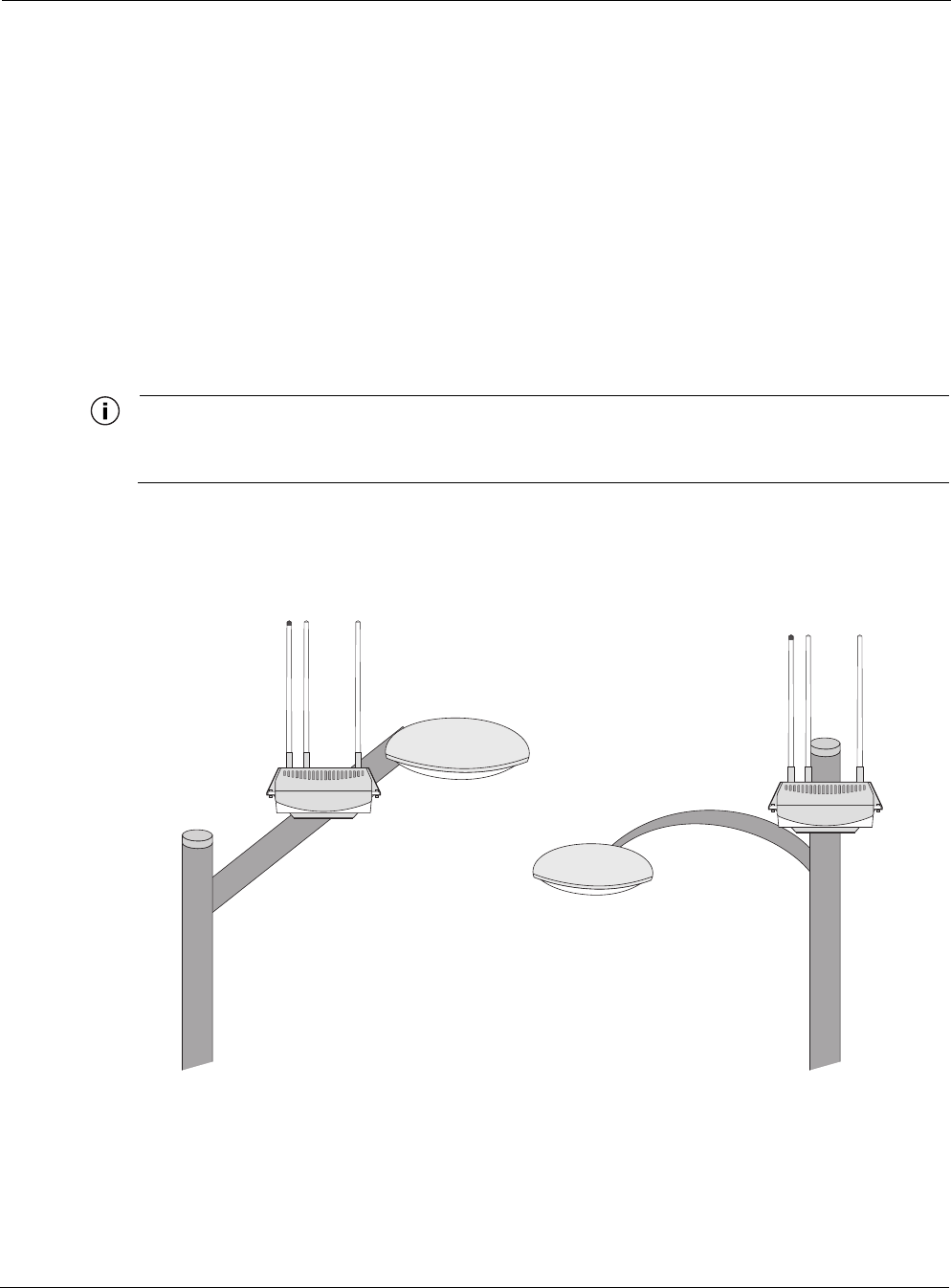
Acceptable options for mounting on a streetlight are shown in Figure 2. In each case the router is
mounted to assure clearance for the antennas above the height of the streetlight.
Figure 2 Example Mounting Location - Antennas Facing Upward
trp_151
Antennas clear of obstruction
Antennas clear
of obstruction
Proper Use of Hose Clamps
Tropos 5320 MetroMesh Router Installation Guide 8
Proper Use of Hose Clamps
The mounting assembly for the Tropos 5320 MetroMesh router contains hose clamps to secure
the router to the mounting structure. Figure 3 illustrates the proper use of the hose clamps. The
clamps must be routed through slots in the pole bracket as shown in the figure, and then attached
to the pole and tightened.
Figure 3 Proper Use of Hose Clamps
trp_096
Hose clamp
band
Band goes
behind
inner tabs
Sun shield

Pole, Tower, and Streetlight Mounting Instructions
Tropos 5320 MetroMesh Router Installation Guide 9
Pole, Tower, and Streetlight Mounting Instructions
This section explains how to mount the Tropos 5320 MetroMesh router on a pole, tower, or
streetlight. It is best to mount the router to aluminum or galvanized steel structures. The
mounting brackets are designed to pierce any oxidation layers that are on the outside of the pole,
thereby assuring good quality connection to the grounded structure.
Due to potential antenna obstruction issues, the router is not designed to be directly mounted on
a building wall. If it is necessary to mount the router on a wall, follow the instructions for
mounting on a wooden pole (“Wood Pole Mounting” on page 13), and attempt to mount the
router with maximum possible clearance around the antennas.
Note
The Tropos 5320 MetroMesh router should always be mounted with the top of the router horizontal
and level and with the antennas facing upward.
Note
It is best to attach ground and data cables to the router before sliding the router into the mounted sun
shield, as explained in this section. Before mounting the router, review the wiring instructions in
“Grounding the Tropos 5320 Router” on page 21 and “Connecting a Data Port” on page 29 to
determine the best strategy for the selected location.
Note
Mounting to wood, concrete, or painted poles may require primary grounding for the unit. Check the
national electrical codes in your area for specific rules.
Pole, Tower, and Streetlight Mounting Instructions
Tropos 5320 MetroMesh Router Installation Guide 10
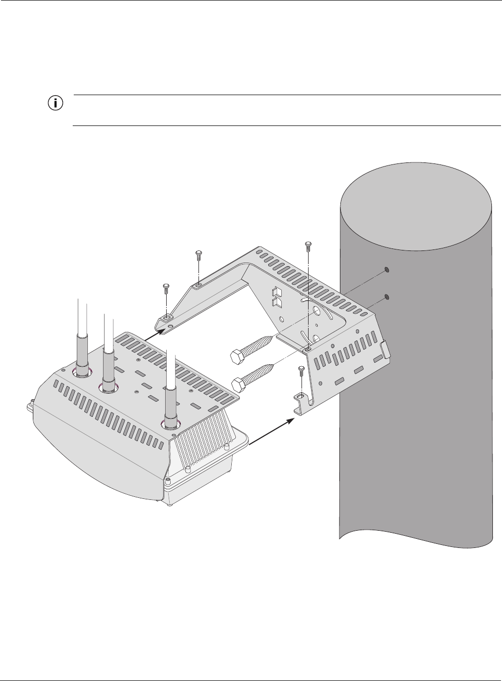
Metal Pole Mounting
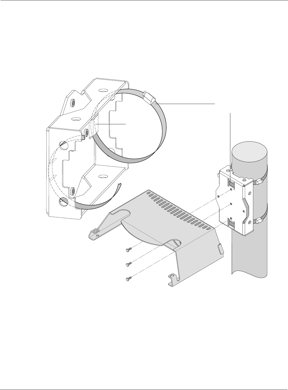
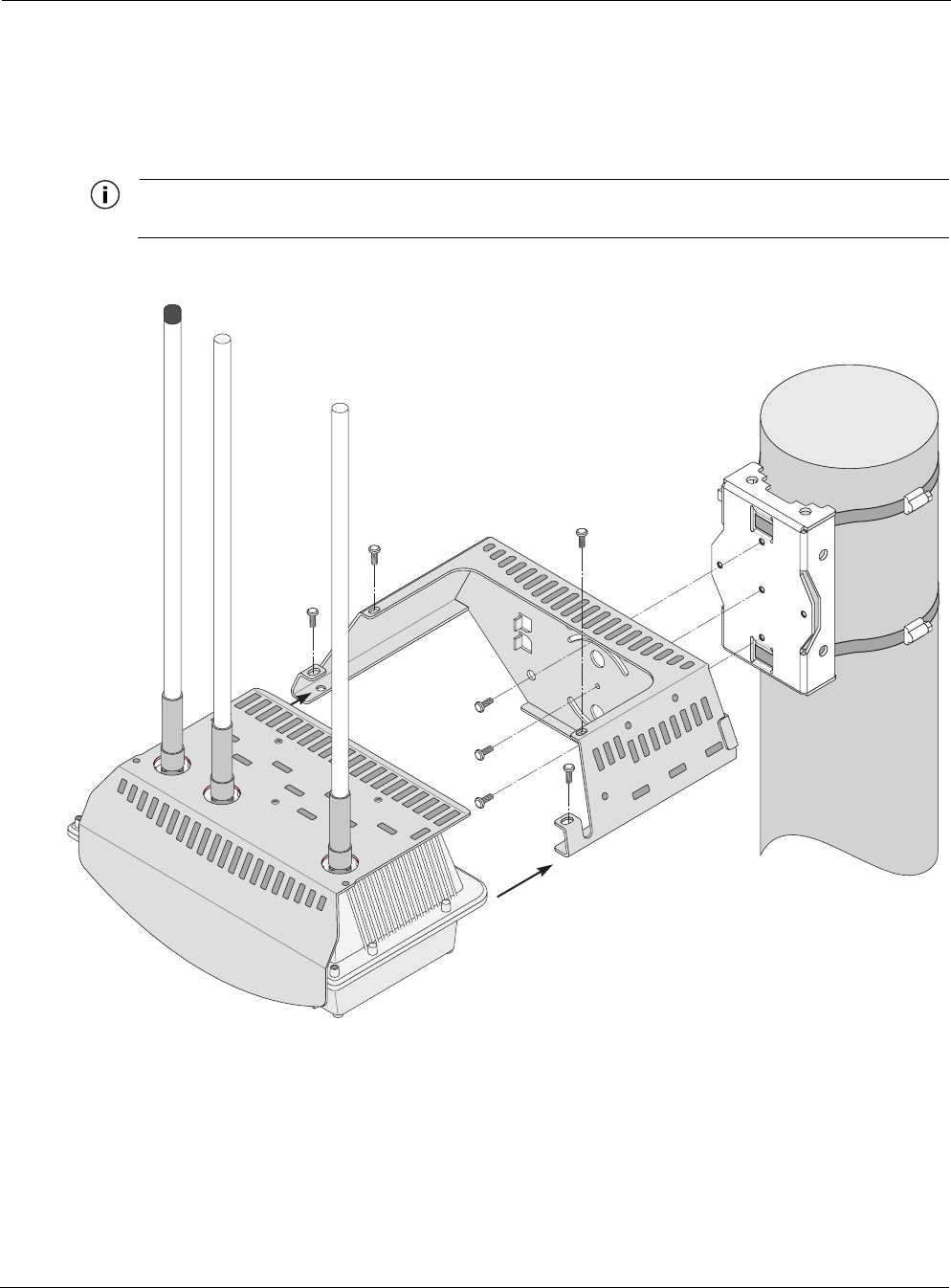
Figure 4 illustrates the proper method of mounting the Tropos 5320 MetroMesh router on an
outdoor metal pole.
Note
Antennas must be clear of obstruction.
Figure 4 Metal Pole Mounting
trp_097
trp_153
Pole bracket
(rotated)
Router
Sun shield

Pole, Tower, and Streetlight Mounting Instructions
Tropos 5320 MetroMesh Router Installation Guide 11
Mount the Tropos 5320 MetroMesh router on a metal pole
1. Select a mounting location. You can attach the router to any pipe or pole with diameter
between 1 inch and 10 inches.
2. Slip the flat portion of the hose clamps under the inner tabs or slots of the pole bracket.
3. Use the hose clamps to attach the pole bracket to the pole. Depending upon the diameter of
the pole, you may need to use a single small clamp, single large clamp, or pair of large
clamps joined together to reach around the pole.
4. Attach the sun shield of the router to the pole bracket with three 5/16-inch machine screws.
Insert one screw through the hole in the center back of the sun shield and the other two
screws through the curved slot tracks. Figure 5 shows the proper screw locations on the back
of the sun shield.
Note
Use anti-seize lubricant, such as Loctite 37230, when screwing the router into the sun shield.
5. Level the sun shield by rotating the unit along the curved slot tracks. A built-in level is
located on the left side of the shield. Tighten the screws.
6. Slide the router into place with the antennas on top and secure it at the end with four #10-32
hex head machine screws.
To continue installing the router, see “Connecting Cable Attached Antennas” on page 18.
Pole, Tower, and Streetlight Mounting Instructions
Tropos 5320 MetroMesh Router Installation Guide 12
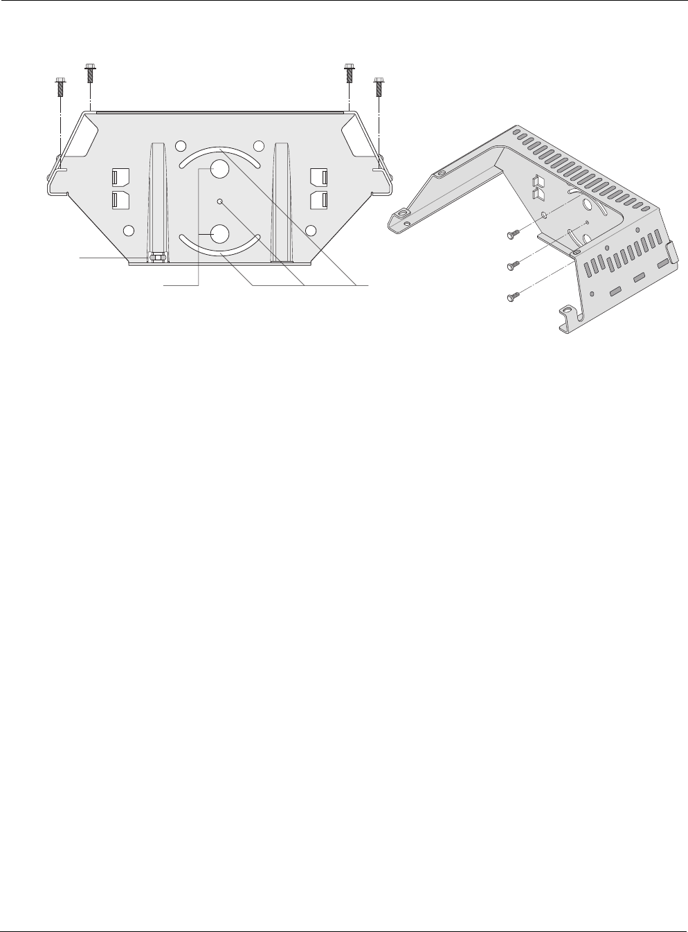
Figure 5 Sun Shield Connections
trp_154
Bubble
level
Use lag bolts
to attach sun shield
to wooden pole
Screws to attach router to sun shield
Use machine screws
to attach sun shield
to pole bracket
Pole, Tower, and Streetlight Mounting Instructions
Tropos 5320 MetroMesh Router Installation Guide 13
Wood Pole Mounting
Figure 6 shows a typical installation with the Tropos 5320 MetroMesh router mounted on an
outdoor wood pole.
Note
Antennas must be clear of obstruction.
Figure 6 Wood Pole Mounting
trp_155
Router
Sun shield
Pole, Tower, and Streetlight Mounting Instructions
Tropos 5320 MetroMesh Router Installation Guide 14
Mount the Tropos 5320 MetroMesh router on a wood pole
1. Select a mounting location. You can attach the router to any outdoor wood pole of diameter
at least 1 inch.
2. Attach the sun shield of the router to the pole with two 5/8-inch bolts, making sure that the
shield is level. Figure 5 on page 12 shows the proper bolt locations on the back of the sun
shield. The bolts should be at least 3 inches in length.
3. Slide the router into place and secure it at the end with four #10-32 hex head machine
screws.
To continue installing the router, see “Connecting Cable Attached Antennas” on page 18.
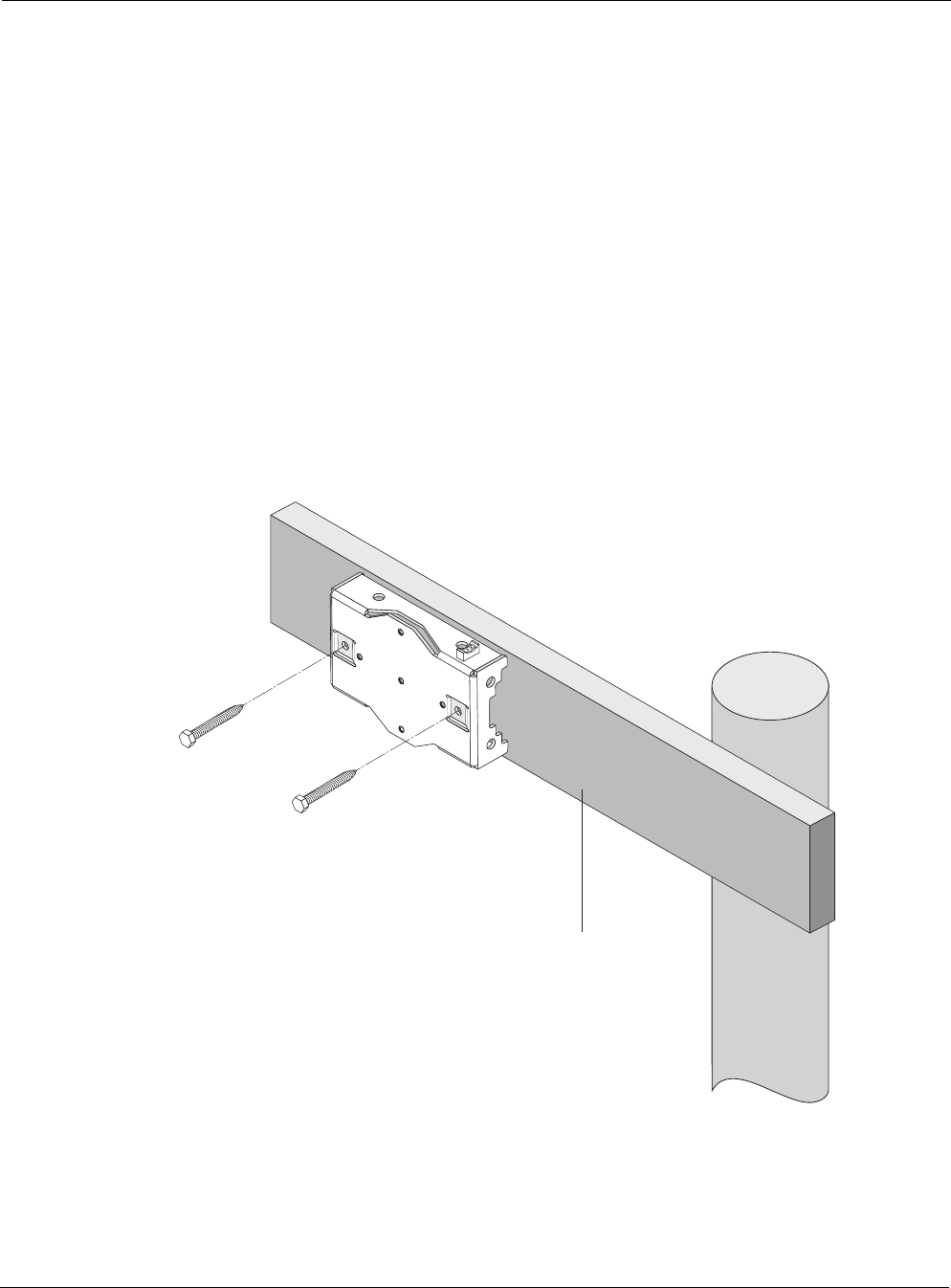
Wood Brace Mounting
You can mount the pole bracket directly on a wood brace without using pole hose clamps, as
shown in Figure 7.
Figure 7 Wood Brace Mounting Option
trp_141
Wood brace
1/4" lag bolts
2-1/2" minimum

Pole, Tower, and Streetlight Mounting Instructions
Tropos 5320 MetroMesh Router Installation Guide 15
Mount the Tropos 5320 MetroMesh router on a wood pole
1. Select a mounting location. You can attach the router to any wood brace.
2. Attach the pole bracket to the wood brace with two 1/4-inch lag bolts that are at least 2 1/2
inches in length, making sure that the wood brace is level.
3. Attach the sun shield of the router to the pole bracket with three 5/16-inch machine screws.
Insert one screw through the hole in the center back of the sun shield and the other two
screws through the curved slot tracks. Figure 5 on page 12 shows the proper screw locations
on the back of the sun shield.
Note
Use thread lubricant, such as Loctite 37230, when screwing the router into the sun shield.
4. Level the sun shield by rotating the unit along the curved slot tracks. A built-in level is
located on the left side of the shield. Tighten the screws.
5. Slide the router into place with the antennas on top and secure it at the end with four #10-32
hex head machine screws.
To continue installing the router, see “Connecting Cable Attached Antennas” on page 18.
Pole, Tower, and Streetlight Mounting Instructions
Tropos 5320 MetroMesh Router Installation Guide 16
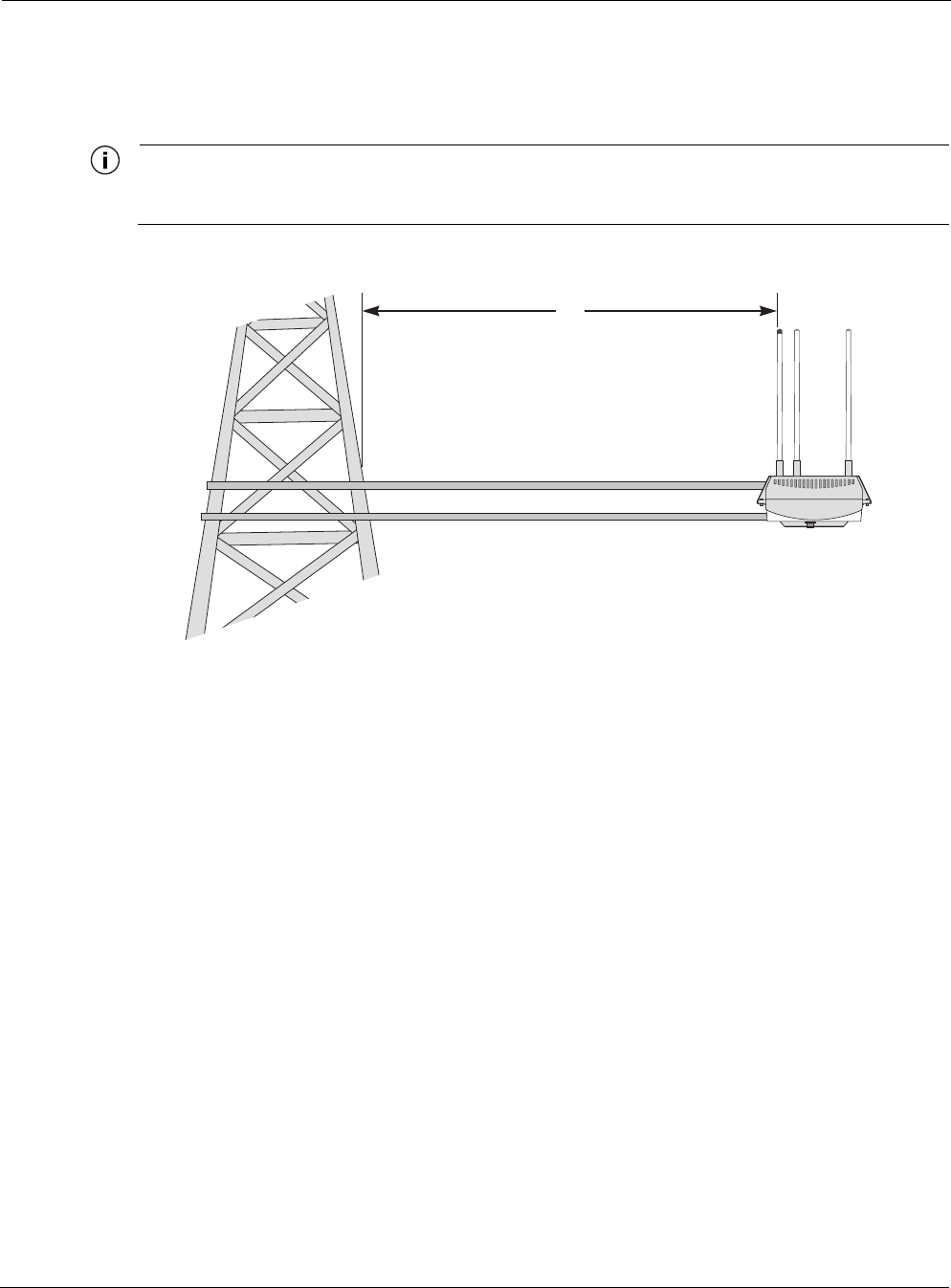
Tower Mounting
You can mount the Tropos 5320 MetroMesh router to an outdoor tower.
Note
At the antenna level, the Tropos 5320 MetroMesh router must be free from metal obstruction within a
4-foot radius (Figure 8).
Figure 8 Tower Mounting
Mount the Tropos 5320 MetroMesh router on a tower
1. Remove the pole bracket from the sun shield.
2. Make a tower bracket by attaching the sun shield directly to any stainless steel or galvanized
steel channel stock.
3. Attach the sun shield to the tower arm so that the top of the shield is horizontal and level.
4. Tighten the mounting bolts.
5. Slide the router into place and secure it at the end with four #10-32 hex head machine
screws.
To continue installing the router, see “Connecting Cable Attached Antennas” on page 18.
trp_156
4'
Brackets not included
Channel stock
Pole, Tower, and Streetlight Mounting Instructions
Tropos 5320 MetroMesh Router Installation Guide 17
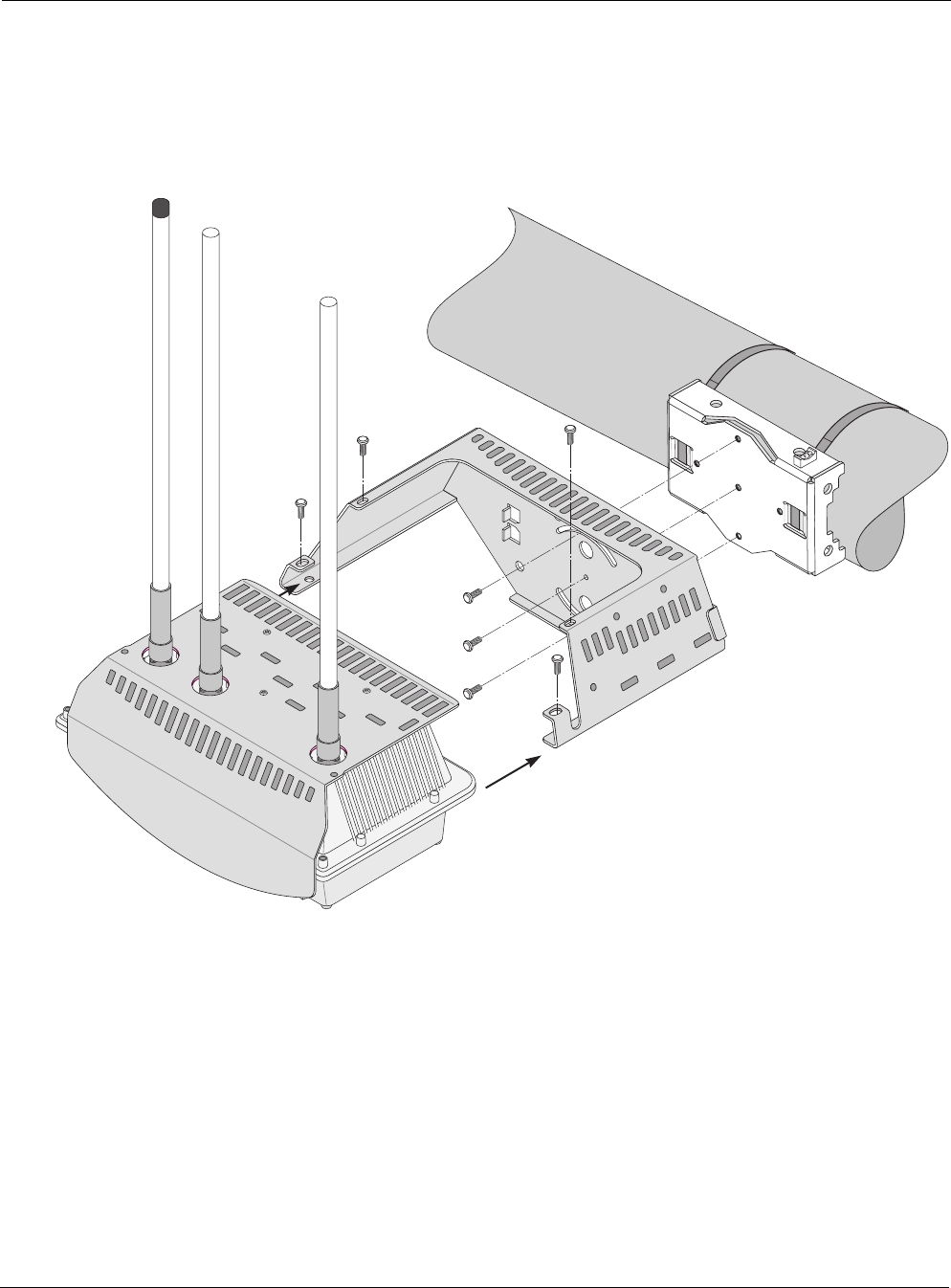
Streetlight Mounting
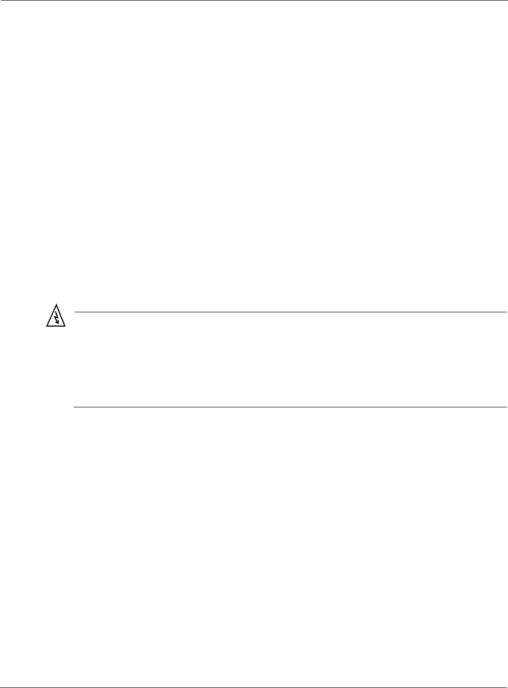
You can mount the Tropos 5320 MetroMesh router on the horizontal or angled arm of a
streetlight. Figure 9 shows a typical streetlight mounting installation.
Figure 9 Streetlight Mounting
Mount the Tropos 5320 MetroMesh router on a streetlight
1. Select a mounting location. You can attach the router to any streetlight arm with diameter 1”
to 10”.
2. Slip the flat portion of the hose clamp under the inside lip of the pole bracket.
3. Use the hose clamps to attach the pole bracket to the streetlight. Depending upon the
diameter of the pole, you may need to use 2 small clamps, 2 large clamps, or 2 pairs of large
clamps joined together to reach around the pole.
trp_157
Pole bracket
Router
Sun shield
Connecting Cable Attached Antennas
Tropos 5320 MetroMesh Router Installation Guide 18
4. Attach the sun shield of the router to the structure with three 5/16-inch machine screws.
Insert one screw through the hole in the center back of the sun shield and the other two
screws through the curved slot tracks.
5. To level the assembly, slide the router loosely into the sun shield, but do not secure it. Level
the sun shield by rotating the unit along the curved slot tracks. A built-in level is located on
the left side of the shield. Maintain the level orientation while you slide the router out of the
sun shield. Tighten the sun shield screws.
6. Slide the router into place and secure it at the end with four #10-32 hex head machine
screws.
To continue installing the router, see “Connecting Cable Attached Antennas” on page 18.
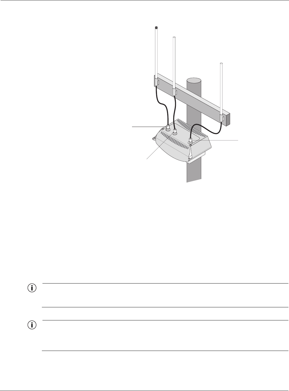
Connecting Cable Attached Antennas
This section applies to external antennas used with the Tropos 5320 router. You can mount the
antenna on a structure and then use cables to attach it to the router. After mounting, secure the
antennas with ThreadLocker Loctite 242 and waterproof them using self-fusing EPR tape. (See
“Installation Accessories” on page 63 for the correct part number.) Figure 10 shows an
installation with external antenna cabling.
Warning
Do not locate the antenna near overhead power lines or other electric light or power circuits,
or where it can come into contact with such circuits. When installing the antenna, take
extreme care not to come into contact with such circuits, as they can cause serious injury or
death. For proper installation and grounding of the antenna, please refer to national and
local codes (e.g. U.S.:NFPA 70, National Electrical Code, Article 810, in Canada: Canadian
Electrical Code, Section 54).
Connecting Cable Attached Antennas
Tropos 5320 MetroMesh Router Installation Guide 19
Figure 10 Connecting External Antennas
Connect antenna cables
1. Mount the antennas in a suitable location, following the instructions supplied with the
antennas.
2. Perform a trial installation of the antenna cables.
3. When you are satisfied with the trial placement of the antenna cables, remove the antenna
connections from the Tropos 5320 MetroMesh router and apply two drops of ThreadLocker
Loctite 242 to the antenna connector thread (Figure 11).
4. Install the antenna cables. Be sure to provide a drip loop to divert water away from the
connector.
Note
To ensure good electrical contact with the antenna, do not get Loctite on the center conductor pin of
the antenna cable or outdoor system connector.
Note
Antenna(s) must be installed by a trained professional. Operating the unit with non-qualified antennas
is a violation of U.S. FCC Rules Part 15.203(c), Code of Federal Regulations, Title 47. See “Approved
Antenna Configurations and Attenuation Settings” on page 48 for a listing of antenna options.
trp_158
trp_101
Cables
from antennas
to unit
802.11a
antenna
802.11b/g Main
antenna
802.11b/g Aux
antenna
Connecting Cable Attached Antennas
Tropos 5320 MetroMesh Router Installation Guide 20
Waterproofing Antenna Connections
Figure 11 illustrates how to waterproof the antenna connections after they are installed. Make
sure that you waterproof the connections at both ends (cable-to-antenna and cable-to-router).
Waterproof the antenna connections
1. Locate the self-fusing EPR waterproofing tape included in the antenna installation kit.
2. Separate the liner from the tape.
3. Pre-stretch the tape and wrap it tightly around the connector.
Figure 11 Waterproofing Antenna Connections
trp_159
Apply tape around
RF cable joints
Apply 2 drops of
Loctite to threads
Grounding the Tropos 5320 Router
Tropos 5320 MetroMesh Router Installation Guide 21
Installing Attached Antennas
The following steps explain how to install antennas that are attached directly to the Tropos 5320
MetroMesh router.
Replace the Tropos 5320 MetroMesh router antennas
1. Turn power off to the router.
2. Remove the screws that secure the router to the sun shield, and slide the router out from the
sun shield.
3. Apply two drops of Loctite Threadlocker 242 to the antenna connector thread.
4. Screw the antennas onto the router, making the connection hand-tight.
5. Locate the self-fusing EPR waterproofing tape included in the antenna installation kit.
6. Separate the liner from the tape.
7. Pre-stretch the tape and wrap it tightly around the connector.
8. Slide the router back into the sun shield and secure it with screws.
Grounding the Tropos 5320 Router
Caution
You must install an external grounding wire if the Tropos 5320 MetroMesh router is
installed on a non-metal pole or if the metal installation structure is not properly
grounded. You must also ground the outdoor data protection device to a bonded pipe
or ground rod. Make sure that grounding is complete before you connect power to the
router.
The grounding arrangement for the Tropos 5320 router is shown in Figure 12.
Grounding the Tropos 5320 Router
Tropos 5320 MetroMesh Router Installation Guide 22
Figure 12 Grounding Arrangement
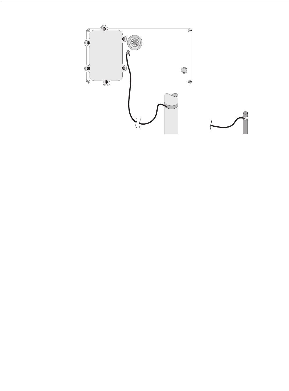
Ground the Tropos 5320 MetroMesh router
1. Insert the grounding screw into the grounding screw hole on the bottom of the router.
2. Connect a length of #10 AWG bare copper wire to the grounding screw and tighten.
3. Connect the other end of the grounding wire to a grounding strap that is attached to a
grounded surface or other earth ground, such as a grounding rod.
trp_104
10 AWG wire
to ground
Grounding strap
on pipe or grounding rod
Grounding
screw
Grounding the Tropos 5320 Router
Tropos 5320 MetroMesh Router Installation Guide 23
Grounding the Data Protection Device
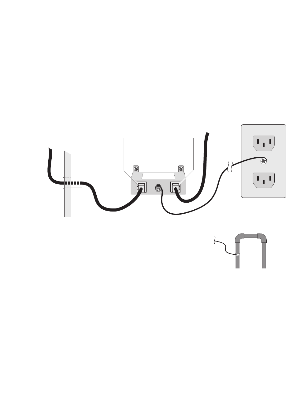
The grounding arrangement for an indoor data protection device is shown in Figure 13.
Ground an indoor data protection device
1. Place the protection device as close to the building entrance as possible.
2. Connect a length of #10 AWG bare copper wire to the ground post on the data protection
device.
3. Connect the other end of the grounding wire to the ground connection of an electrical outlet
or a grounded water pipe.
Figure 13 Grounding the Indoor Network Protection Unit
trp_140
10 AWG wire
to ground
Grounding wire
to elecrtical outlet ground
or water pipe
Indoor network
protection unit
To network
Data cable enters
building wall
through conduit
Shielded RJ45 ports
Connecting Power
Tropos 5320 MetroMesh Router Installation Guide 24
Connecting Power
This section explains the different categories of electrical power and provides procedures for
connecting the outdoor system to power. There are two options for connecting the Tropos 5320
MetroMesh router to a power source:
AC power source (3-wire service) — 3W(P+N+PE) or 3W(2P+PE); 100-480 VAC, 50/60
Hz
NEMA plug, for streetlight photoelectric control power tap (2-wire service) —2W(2P) or
2W(P+N); 100-480 VAC 50/60 Hz
Warning
Before you work on an electrical circuit, make sure the power is off. Turn off the breaker to
the circuit you plan to work on. Post a sign on the service panel so nobody tries to reconnect
power while you are working on the circuits. Double-check the circuit with a circuit tester
before you touch it to make sure the correct breaker has been disconnected.
Caution
You must install an external grounding wire if the Tropos 5320 MetroMesh router is
installed on a non-metal pole or if the metal installation structure is not properly
grounded. You must also ground the outdoor data protection device to a bonded pipe
or ground rod. Make sure that grounding is complete before you connect power to the
router.
Categories of Power
The IEEE/ANSI C62.41 standards (equivalent to the IEC Category IV standards) define
Categories A-C. Equipment designed to a CAT C standard is resistant to much higher energy
transients than one designed to CAT B or CAT A standards. Within a category, a higher voltage
rating denotes a higher transient withstand rating.
Table 1 lists power types and Figure 14 shows hook-ups for the IEEE/ANSI C62.41 Power
Categories power categories.

Connecting Power
Tropos 5320 MetroMesh Router Installation Guide 25
Table 1 IEEE/ANSI C62.41 Power Categories
Category Summary Examples
CAT C Outside and service
entrance
•Service drop from pole to building entrance
•Run between meter and distribution panel
•Overhead line to detached buildings
•Underground lines to well pumps
CAT B Major feeders and
short branch circuits
•Distribution panel devices
•Bus and feeder systems in industrial plants
•Heavy appliance outlets with “short” connections to the
service entrance
•Lightning systems in commercial buildings
CAT A Outlets and long
branch circuits
•All outlets at more than 10 m (30 ft) from Category B with
wires #14-10
•All outlets at more than 20 m (60 ft) from Category C with
wires #14-10
Connecting Power
Tropos 5320 MetroMesh Router Installation Guide 26
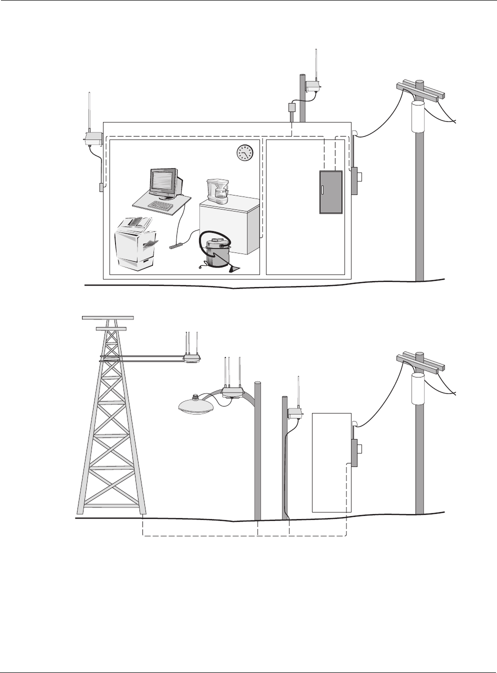
Figure 14 IEEE/ANSI C62.41 Power Categories
trp_105
trp_164
Category A Category B
Outdoor units powered from
distribution panel are in
Overvoltage Installation Category B
Category C
Outdoor units powered from electrical meter are in
Overvoltage Installation Category C
Category C
Connecting Power
Tropos 5320 MetroMesh Router Installation Guide 27
Connecting to AC Power (Category C)
The AC power connections for a Category C AC power source are shown in Figure 15.
Figure 15 Connecting Category C AC Power
Connect an AC power source
1. Verify that the service voltage is 100-480 VAC 50/60 Hz.
2. Verify that power is turned off on the designated circuits.
3. Install 1/2-inch liquid-tight conduit from the building entrance point to within 3 feet of the
outdoor system.
4. Run 3-wire AC service through the conduit.
5. Connect the conduit to a junction box. The conduit and junction box must be IEEE/ANSI
compliant and suitable for outdoor use.
Note
Data and power must never be enclosed in the same conduit.
6. Connect the AC cable to the router and tighten the nut hand-tight. See Figure 16.
7. Connect the Tropos 5320 MetroMesh router to a 100-480 VAC 50/60 Hz CAT C power
source.
8. Reenergize the circuit and confirm that power to the router comes on.
trp_106
AC power
from meter
AC wiring in
junction box
To power
source
Green wire
Wire nuts
White wire
Black wire
To outdoor unit
Connecting Power
Tropos 5320 MetroMesh Router Installation Guide 28
Note
The Tropos 5320 MetroMesh router is equipped with additional AC surge protection and dual fuse
branch circuit protection. Additional ISA branch circuit protection is not required in the upstream power
distribution.
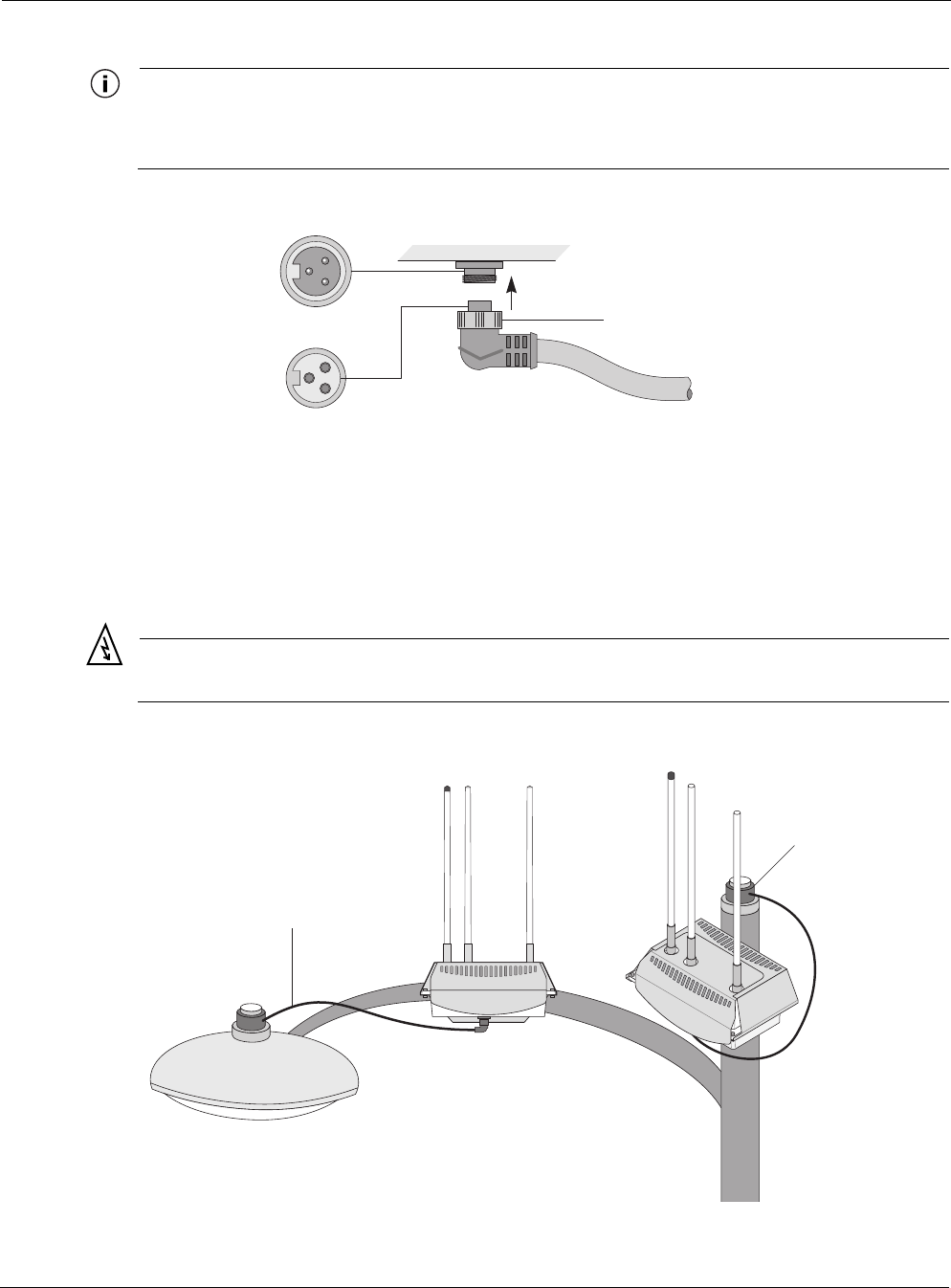
Figure 16 Connecting the AC Power Cable
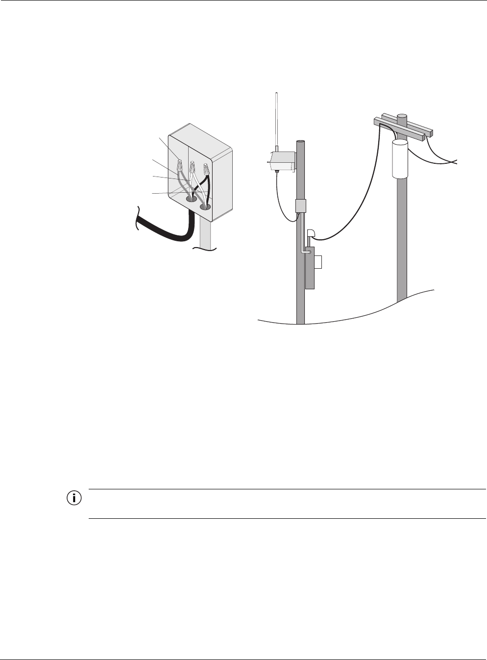
Connecting to Streetlight Power (Category C)
The power connections for Category C streetlight power are shown in Figure 17. Use the 3-
prong NEMA twist-lock adapter with twist-lock style photoelectric controls for outdoor lighting
commonly used by utilities. The NEMA twist-lock adapter can be used only with UL 773 listed
outdoor lighting controls rated for and operated at 100-480 VAC 50/60 Hz.
Warning
Be extremely careful when connecting to Category C streetlight power.
Figure 17 Connecting Streetlight Power
trp_107
Tighten nut to secure
power connection
AC power from
power adapter
on photosensor
AC power from
power adapter
on photosensor

Connecting a Data Port
Tropos 5320 MetroMesh Router Installation Guide 29
Warning
Connect the outdoor system only to a twist-lock style outdoor lighting control powered by
100-480 VAC 50/60 Hz. Do not connect it to twist-lock style outdoor lighting controls
powered by higher voltage.
Connect a streetlight power source
1. Verify that the service voltage is 100-480 VAC 50/60 Hz.
2. Verify that power is turned off on the designated circuits.
3. Remove the photosensor from the streetlight.
4. Connect the NEMA 3 prong plug from the Tropos 5320 MetroMesh router to the
photosensor connector on the street light.
5. Connect the photosensor to the top of the NEMA 3 prong plug.
6. Connect the AC plug to the router and tighten hand-tight.
7. Reenergize the circuit and confirm that power to the router comes on.
Note
The Tropos 5320 MetroMesh router is equipped with additional AC surge protection and dual fuse
branch circuit protection. Additional ISA branch circuit protection is not required in the upstream power
distribution.
Note
Do not leave connectors open to the environment. Connectors should be covered with closure caps
when not in use. Closure caps should be tightened to be snug.
Connecting a Data Port
The Tropos 5320 MetroMesh router is equipped with two Ethernet ports that support RJ45
connectors.
Note
The Tropos 5320 MetroMesh router is shipped pre-configured. For post-installation changes in
configuration, you can communicate with the router by way of its wireless connection. For more
information, see the Tropos Networks Configuration Guide.
Connecting a Data Port
Tropos 5320 MetroMesh Router Installation Guide 30
Note
Only use shielded Cat5 cable rated for outdoor use. For protection against risk of fire, electrical hazard
and to ensure the reliable operation of this equipment, the shields of the Cat5 cable must be properly
terminated and bonded to the unit and to the protective earth (PE) at the building entrance.
Note
National Electrical Codes (NEC) Article 800 requires the use of Agency Listed (UL/CSA) Building
Entrance Protector for all power and communications cables entering a building. The NEC intends by
Article 800 to protect the building and occupants from fires caused by transient voltage and current
surges.
Warning
DC voltage may be present on RJ-45 pins 4,5 (+) and 7,8 (-)
Attention
Une tension continue peut être présente sur les broches RJ-45 4, 5 (+) et 7, 8 (-).
Note
This is not a mid-span powered device. Never attempt to daisy-chain Power Over Ethernet devices.
Connecting a Data Port
Tropos 5320 MetroMesh Router Installation Guide 31
Figure 18 illustrates the method for routing cables to the Tropos 5320 MetroMesh router. Use
the RJ45 jacks for port connection.
Figure 18 Options for Connecting a Data Port
trp_111
Watertight access cover
cable glands
Cable terminated with
RJ45 jack for port
connection
Shield
termination
Connecting a Data Port
Tropos 5320 MetroMesh Router Installation Guide 32
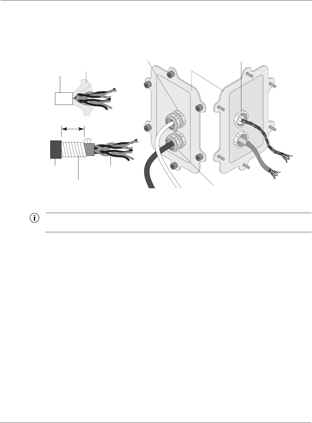
Figure 19 shows the layered shield and jacket for the data cable, which must be removed to
expose the inner cable and twisted pairs.
Figure 19 Data Cable Detail
Note
Attach ground and data cables to the router before sliding it into the sun shield.
Connect to the data port
1. Verify that power is turned off on the designated circuits.
2. Run shielded Category 5 Ethernet cable appropriate for outdoor use from a data protection
unit to the Tropos 5320 MetroMesh router.
3. Connect one end of the Category 5 cable to the protection unit.
4. Remove the connector access cover on the bottom of the router.
5. Run raw cables for the Management or LAN port, or both, through the bulk head openings,
allowing sufficient length to terminate the cables without causing crowding in the
connection area. See Figure 20.
trp_117
Watertight bulkhead
cable glands
Cable
Outer
jacket
Tw i s t e d
pairs
Securely tighten gland
for weathertight seal
Conductive
shield
Belfoil
shield
Terminate cable shield
at cable gland
1/2 inch
Connector access
cover
Connecting a Data Port
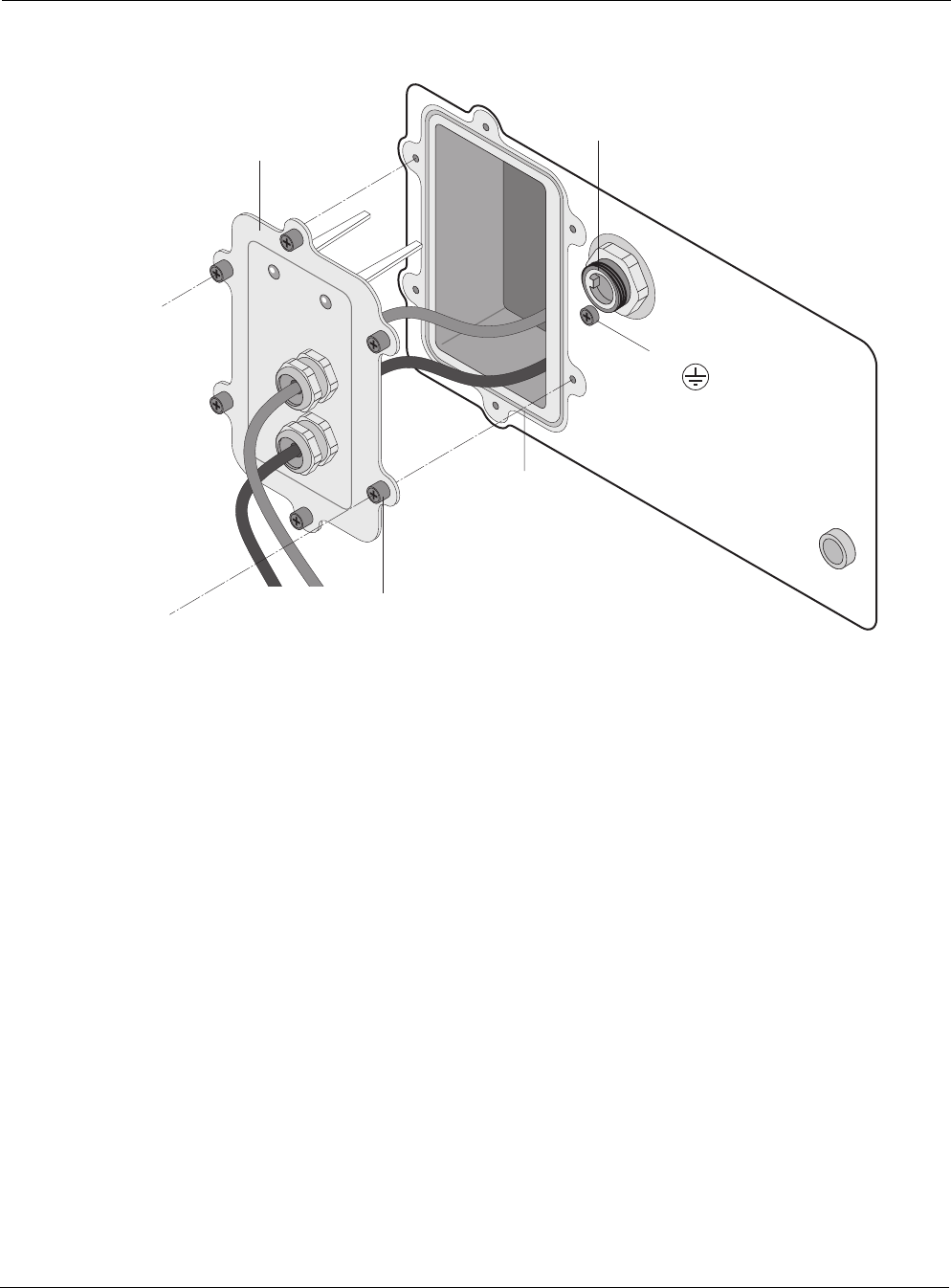
Tropos 5320 MetroMesh Router Installation Guide 33
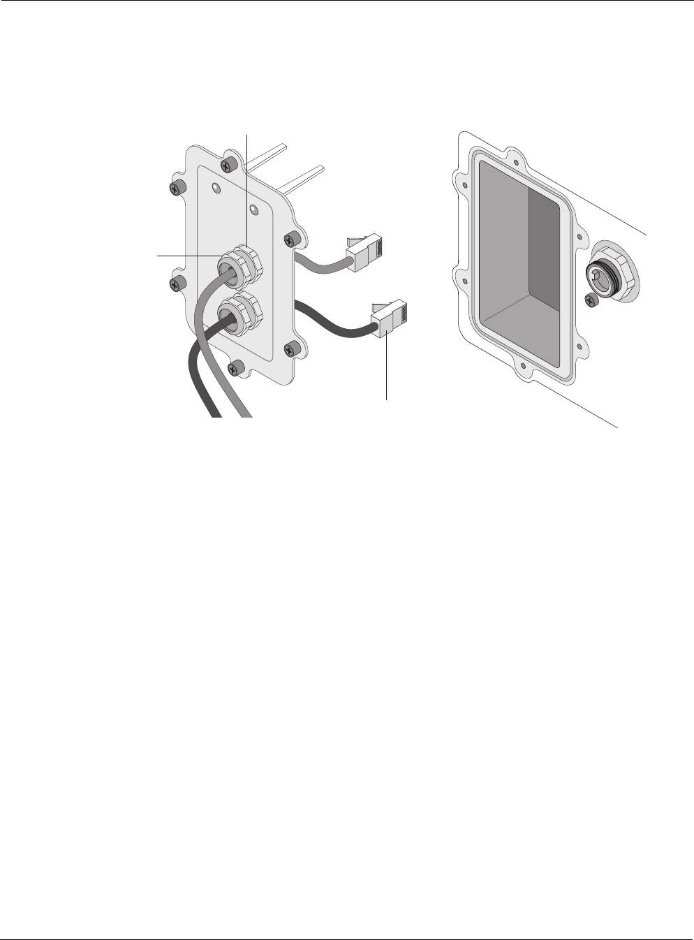
Figure 20 Data Port Connection
6. Connect the cable ends that were routed through the connector access cover to the LAN and
Management ports on the router. Use an appropriate RJ45 8-pin modular plug to terminate
the cables at the desired lengths. The outer jacket and conductive shield must be stripped to
expose the twisted pairs for attachment, as shown in Figure 19. The proper location of the
connections on the circuit board is shown in Figure 21.
7. Verify that the protection unit is properly grounded.
tr
p
_112
O-ring
AC power
connector
Cable guides
Ground bolt
Connector access cover
Tighten six screws to
fasten bulkhead plate
Resetting the Router
Tropos 5320 MetroMesh Router Installation Guide 34
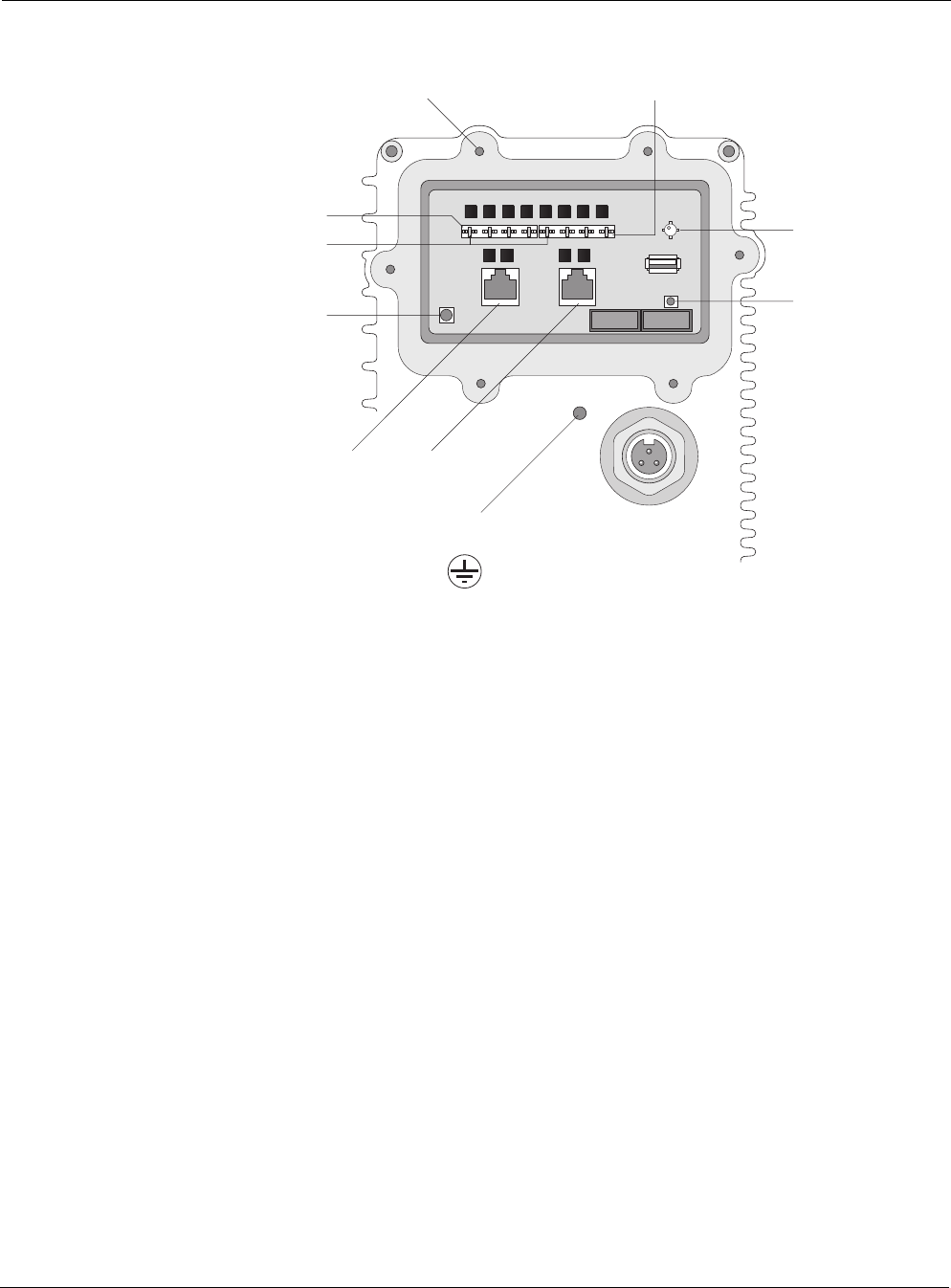
Figure 21 Circuit Board Connection Locations
Resetting the Router
You can use the Reset button on the circuit board to reset the hardware and software and to turn
the router off if it is operating on battery power.
Perform a hardware reset
1. Remove the connector access cover on the bottom of the router.
2. Press the Reset button for one second.
Turn the battery-powered router off
Follow these steps if AC power is off and the router is running on battery power:
1. Remove the connector access cover on the bottom of the router.
2. Press and hold the Reset button for 3-5 seconds.
trp_110
AC power
connector
Management
port
Reset
Brown
Management
punch-down block
LAN punch-down blockScrew holes for access cover
LED
LED
Threaded hole for
grounding bolt
LAN
port

Connecting Peripherals
Tropos 5320 MetroMesh Router Installation Guide 35
Connecting Peripherals
The Tropos 5320 MetroMesh router can be configured to source DC power on the Ethernet
connector pins 4,5 and 7,8, This capability allows the router to power remote peripherals such as
backhaul point-to-point radios, video cameras, or fiber optic transceivers. The Tropos Power
over Ethernet (PoE) power sourcing capability is a fully isolated supply and can be used to
power either positive or negative polarity peripherals.
The Tropos PoE power sourcing capability differs from the IEEE 802.3af standard in the
following ways:
Tropos PoE includes support for multiple voltages; the 802.3af standard supports only 48V
operation.
Tropos PoE does not include support for auto-discovery.
Many IEEE 802.3af-compliant power devices (PDs) will operate using the Tropos power
sourcing equipment capabilities.
The Tropos 5320 MetroMesh router can supply up to a total of 30W of DC power distributed to
the LAN port, Management port, or both. Each port must be configured for the same voltage. To
configure the voltage, use the Tropos Configuration Utility (see the Tropos Networks User
Guide) or an element management system such as Tropos Control (see the Tropos Control EMS
Installation and User Guide). The DC output voltage can be configured to 12Vdc, 24Vdc,
48Vdc, or to the Off state (0Vdc). Table 2 lists the maximum power output as a function of
voltage.
In the event of an over-current or short-circuit fault event, the Tropos 5320 MetroMesh router
will remove PoE output for three to five seconds before attempting to resume sourcing power to
the peripheral device.
Note
When the software restarts following a software upgrade, the PoE output will experience a disruption
for the period of the restart.
If the battery backup capability is installed, PoE output power is unaffected by the temporary
loss of AC power. The power sourcing feature continues to function during battery backup
operation (see “Battery Backup Operation” on page 37).
Table 2 PoE Power Sourcing Power Output
Voltage Max PoE Power Output
12Vdc 30W
24Vdc 30W
48Vdc 30W
Connecting Peripherals
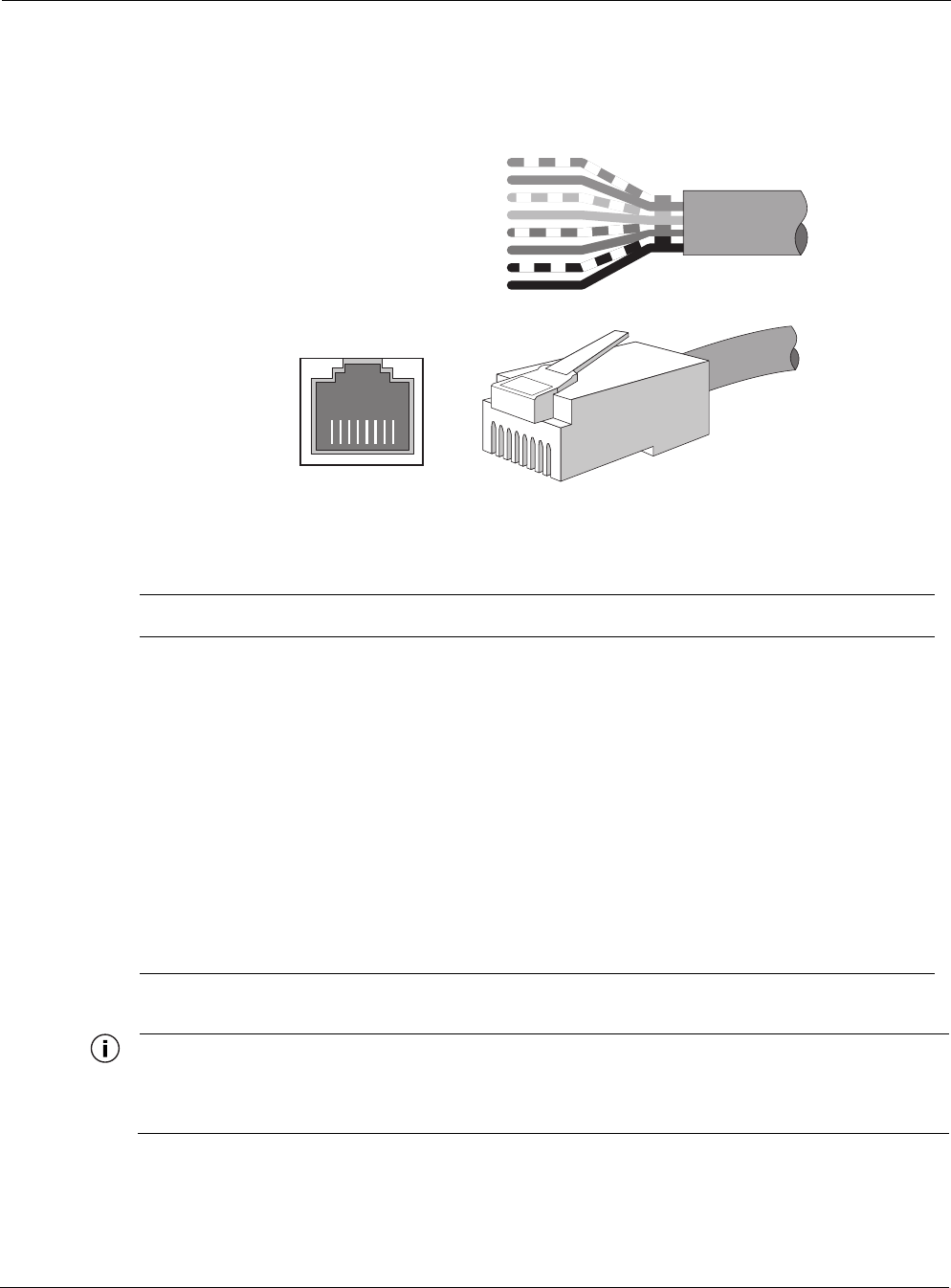
Tropos 5320 MetroMesh Router Installation Guide 36
Figure 22 shows the pin locations for the RJ45 connector, and Table 3 shows the associated pin
descriptions.
Figure 22 RJ45 Pin Locations
Note
Only use shielded Cat5 cable rated for outdoor use. For protection against risk of fire, electrical hazard
and to ensure the reliable operation of this equipment, the shields of the Cat5 cable must be properly
terminated and bonded to the unit and to the protective earth (PE) at the building entrance.
Table 3 RJ45 Pin Descriptions for Data Connection
Pin T/R Signal Color Description
1 T TXD+ Orange-White TX Data 10/100BaseT
2 R TXD- Orange TX Data 10/100BaseT
3 T RXD+ Green-White RX Data 10/100BaseT
4 R PoE+ Blue Power output, 0, 12, 24, 48 Vdc (+)
5 T PoE+ Blue-White Power output, 0, 12, 24, 48 Vdc (+)
6 R RXD- Green RX Data 10/100BaseT
7 T PoE- Brown-White Power output, 0, 12, 24, 48 Vdc (-)
8 R PoE- Brown Power output, 0, 12, 24, 48 Vdc (-)
trp_109
Category 5 cable
RJ45 port
RJ45 jack
8
1
2
3
4
5
6
7
Brown
Orange/white
Orange
Green/white
Blue
Blue/white
Green
Brown/white
18765432 7
68
5
4
3
2
1
Battery Backup Operation
Tropos 5320 MetroMesh Router Installation Guide 37
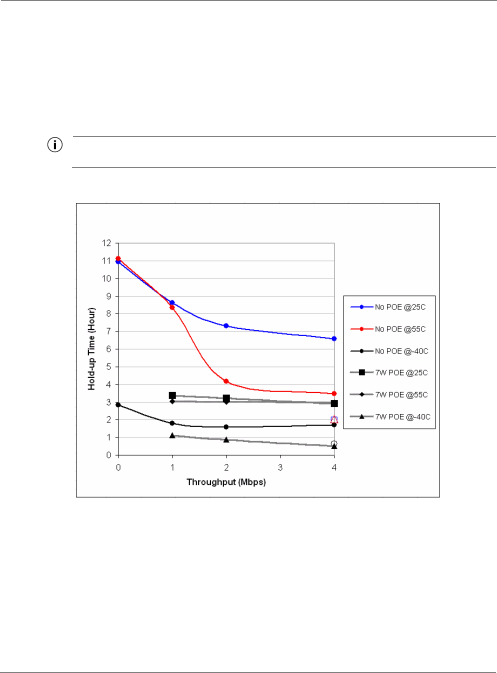
Battery Backup Operation
The Tropos 5320 MetroMesh router may contain an automatically recharging battery, which
provides an integrated uninterruptible power supply (UPS). The available backup time depends
upon the level of network traffic serviced by the router and the ambient temperature. Figure 24
shows the relationship between average throughput and battery uptime. The Tropos 5320 router
will typically recharge the UPS in approximately 10 hours.
Note
The internal battery is not field replaceable.
Figure 23 Average Battery Backup Time
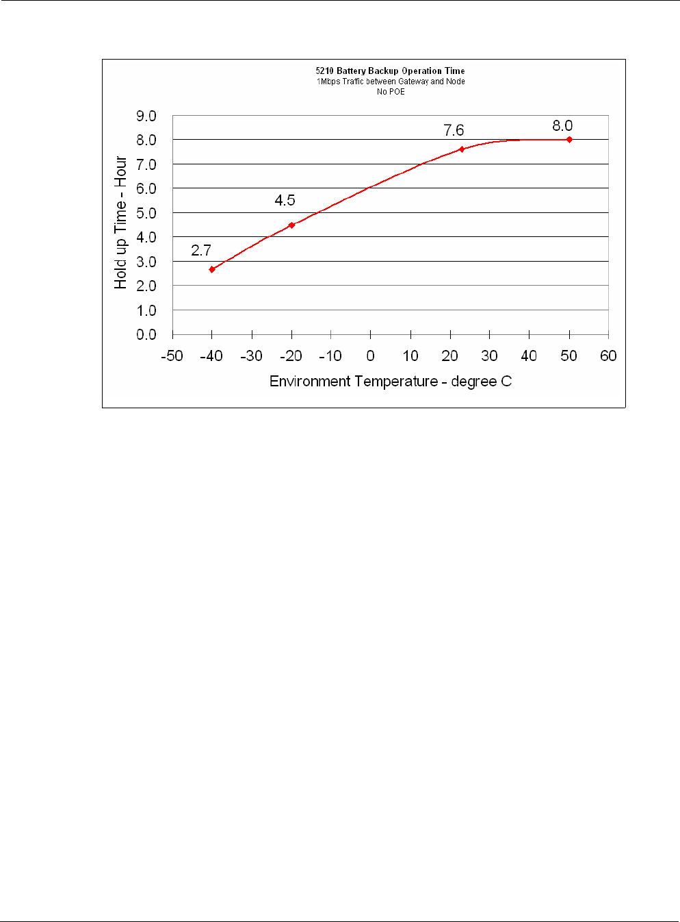
The battery is equipped with a small internal heater that enhances battery life in very cold
operating conditions. When the ambient temperature of the unit approaches -12 degrees C, the
internal heater is activated. An active internal battery heater consumes power; therefore, the
average power consumption of the Tropos 5320 MetroMesh router increases slightly in
extremely cold weather conditions. Figure 24 shows the battery discharge hold time as a
function of ambient temperature.
Safety Information for the Tropos MetroMesh Router
Tropos 5320 MetroMesh Router Installation Guide 38
Figure 24 Average Battery Backup Time vs. Temperature
Safety Information for the Tropos MetroMesh
Router
The Federal Communications Commission (FCC) with its action in ET Docket 96-8 has adopted
a safety standard for human exposure to RF electromagnetic energy emitted by FCC certified
equipment. The Tropos 5320 products meet the uncontrolled environmental limits found in
OET-65 and ANSI C95.1, 1991. Proper operation of this radio according to the instructions
found in this manual and the hardware and software guides on the Tropos 5320 MetroMesh
routers result in user exposure that is substantially below the FCC recommended limits.
Follow these guidelines to ensure safe operation of the Tropos 5320 MetroMesh routers:
Do not touch or move the antenna(s) while the unit is transmitting or receiving.
Do not hold any component containing a radio such that the antenna is very close to or
touching any exposed parts of the body, especially the face or eyes, while transmitting.
Do not operate the radio or attempt to transmit data unless the antenna is connected;
otherwise, the radio may be damaged.
Use in specific environments:
Do not operate a portable transmitter near unshielded blasting caps or in an explosive
environment unless it is a type especially qualified for such use.
The use of wireless devices in hazardous locations is limited to the constraints posed by
the safety directors of such environments.

Safety Information for the Tropos MetroMesh Router
Tropos 5320 MetroMesh Router Installation Guide 39
The use of wireless devices on airplanes is governed by the Federal Aviation
Administration (FAA).
The use of wireless devices in hospitals is restricted to the limits set forth by each
hospital.
Antenna use:
The Tropos 5320 MetroMesh routers must be used only with Tropos-approved
components and antennas. See “Approved Antenna Configurations and Attenuation
Settings” on page 48 for details.
In order to comply with FCC RF exposure limits, dipole antennas should be located at a
minimum distance of 7.9 inches (20 cm) or more from the body of all persons.
High-gain, wall-mount or mast-mount antennas are designed to be professionally
installed and should be located at a minimum distance of 24 inches (60 cm) or more from
the body of all persons. Please contact your professional installer, VAR, or antenna
manufacturer for proper installation requirements.
Battery backup:
The Tropos 5320 MetroMesh router may contain a lithium-ion battery. To avoid the
possibility of an explosion, the Tropos 5320 MetroMesh router should not be exposed to
any temperatures higher than 85 degrees C.
Tropos 5320 MetroMesh Router Installation Guide 40
2Power Consumption
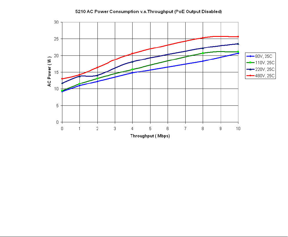
Several factors influence the power consumption at any given time, including the level of
network traffic and whether a powered peripheral device is connected to the LAN or
Management port of the Tropos 5320 MetroMesh Router. Temperature may also influence the
power consumption for units configured with battery backup, due to the internal freeze
protection capability associated with the internal battery module. Figure 25 shows the basic
relationship between throughput and AC power consumption at normal temperatures.
Figure 25 AC Power Consumption vs. Throughput with PoE Output Disabled
Tropos 5320 MetroMesh Router Installation Guide 41
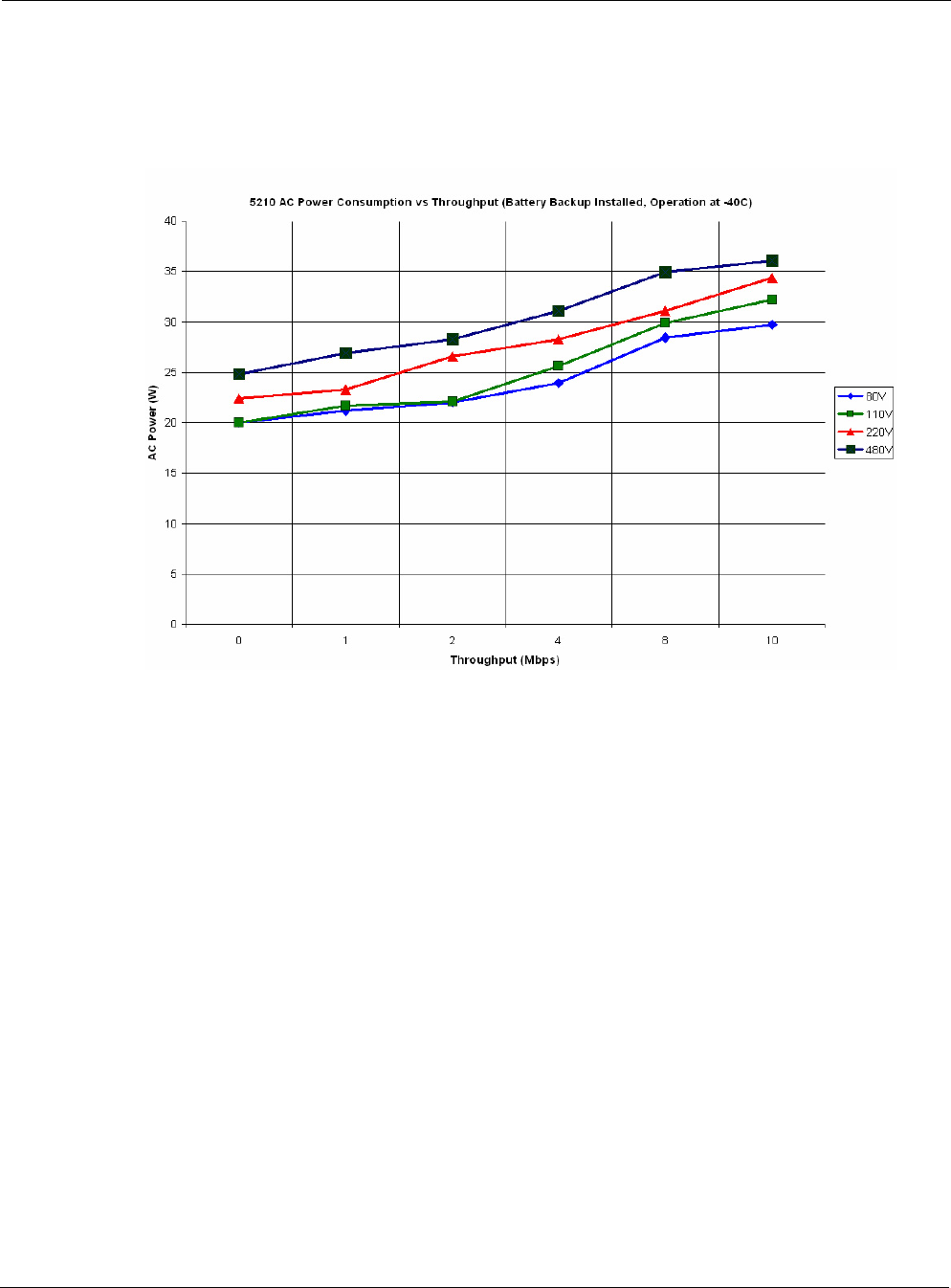
When a Tropos 5320 MetroMesh Router is equipped with a battery and the router is exposed to
cold temperatures (below -12 degrees C), the internal heater associated with the battery is
activated. This causes the router to draw additional AC power, as shown in Figure 26.
Figure 26 AC Power Consumption vs. Throughput (Battery Backup, -40o C)

Tropos 5320 MetroMesh Router Installation Guide 42
3Product Specifications
The tables in this chapter contain specifications for the Tropos 5320 MetroMesh routers:
“Physical Specifications - Tropos 5320 Router” on page 42
“Interfaces” on page 44
“Power Options / Consumption” on page 46
“Power Over Ethernet - Power Sourcing” on page 47
“Certifications, Other” on page 47
Table 4 Physical Specifications - Tropos 5320 Router
Physical Dimensions Height Width Depth
Inches 5.3 13.2 7.9
Centimeters 13.5 33.5 20.1
Weight
lbs - maximum 14 Includes all brackets
and sun shields
Kg - maximum 6.35
Mounting Pole Diameter 1” to 10”
Temperature Min Max
AC Powered Operating Range -40o C55C
Storage Range -45o C85C
Weather
Weather Rating UL579/IEC 60529 IP67
Wind Survivability > 165 mph
Wind Loading (165 mph) < 300 newtons
Projected Area 0.7 sq. ft. (101 sq. in.)
Corrosion Resistance MIL-STD-810F 509.4 Salt Fog
Color
Color Gloss white
Shock and Vibration
Operational: ETSI 300-19-2-4
Specification T41.E,
class 4M3

Tropos 5320 MetroMesh Router Installation Guide 43
Transportation: ISTA 2A
Random Bounce
Random Vibration
6 Corner Drop Test
Reliability
Reliability (MTBF): 505,787 hours demonstrated
Field failure rate 1.73%
Table 4 Physical Specifications - Tropos 5320 Router (continued)

Tropos 5320 MetroMesh Router Installation Guide 44
Table 5 Interfaces
Data Interface Maximum Distance (ft) Connector
IEEE 802.3 10/100BaseT 600 (10BaseT Duplex Setting)
300 (100BaseT Duplex Setting)
RJ45
Management Interface Maximum Distance (ft) Connector
IEEE 802.3 10/100Base T 600 (10BaseT Duplex Setting)
300 (100BaseT Duplex Setting)
RJ45
802.11b/g Wireless Interface
Standard IEEE 802.11b/g Wi-Fi
Frequency Range 2400 to 2485 MHz ISM Band
Modulation DSSS; DBPSK @ 1 Mbps,
DQPSK @ 2 Mbps,
CCK @ 5.5 and 11 Mbps
OFDM @ 54, 48, 36, 24, 18, 12, 6
Rx Sensitivity -100dBm (1 Mbps)
-95dBm (2 Mbps)
-93dBm (5.5 Mbps)
-91dBm (11 Mbps)
-94dBm (6 Mbps)
-93dBm (9 Mbps)
-92dBm (12 Mbps)
-89dBm (18 Mbps)
-86dBm (24 Mbps)
-83dBm (36 Mbps)
-78dBm (48 Mbps)
-76dBm (54 Mbps)
Rx Saturation
Maximum Power at Antenna Port
-5dBm (1 Mbps)
-5dBm (2 Mbps)
-5dBm (5.5 Mbps)
-5dBm (11 Mbps)
-5dBm (6 Mbps)
-5dBm (9 Mbps)
-5dBm (12 Mbps)
-10dBm (18 Mbps)
-30dBm (24 Mbps)
-35dBm (36 Mbps)
-35dBm (48 Mbps)
-35dBm (54 Mbps)

Tropos 5320 MetroMesh Router Installation Guide 45
802.11a Wireless Interface
Standard IEEE 802.11a Wi-Fi
Frequency Range 2400 to 2485 MHz ISM Band
Modulation OFDM @ 54, 48, 36, 24, 18, 12, 6
Rx Sensitivity -94dBm (6 Mbps)
-93dBm (9 Mbps)
-92dBm (12 Mbps)
-89dBm (18 Mbps)
-86dBm (24 Mbps)
-83dBm (36 Mbps)
-78dBm (48 Mbps)
-76dBm (54 Mbps)
Rx Saturation
Maximum Power at Antenna Port
-30dBm (6 Mbps)
-30dBm (9 Mbps)
-30dBm (12 Mbps)
-30dBm (18 Mbps)
-30dBm (24 Mbps)
-35dBm (36 Mbps)
-35dBm (48 Mbps)
-35dBm (54 Mbps)
Antennas
Antennas External
Antenna Diversity 802.11b/g: Transmit/Receive
802.11a: No diversity
Impedance 50 ohms
VSWR 1.5 : 1
Connectors (three) N (female)
Indicator - Status Lamp Red/Green
Table 5 Interfaces (continued)

Tropos 5320 MetroMesh Router Installation Guide 46
Table 6 Power Options / Consumption
Single Phase VAC 100-480 VAC 50/60 Hz
IEEE/ANSI C62.41 CAT C Power Source
IEC Category IV Power Source
23W/60W typical/max
Protection Circuits
Antenna Protection <= 0.5µJ for 3kA @ 8/20µS Waveform
EN61000-4-2 Level 4 ESD Immunity
EN61000-4-5 Level 4 Surge Immunity
AC Input Protection IEEE/ANSI C62.41 Category C 10kA @
8/20uS Waveform; 36kA per phase L-L,
L-N, L-PEWh
EN61000-4-2 Level 4 ESD Immunity
EN61000-4-5 Level 4 Surge Immunity
EN61000-4-4 Level 4 EFT Immunity
Integrated Branch Circuit Protection
Class CC-Fuse: Littlefuse KLDR Time-
Delay 20A
Data Port Protection EN61000-4-2 Level 4 ESD Immunity
EN61000-4-5 Level 4 Surge Immunity

Tropos 5320 MetroMesh Router Installation Guide 47
Table 7 Power Over Ethernet - Power Sourcing
LAN and/or Management Port + on pins 4,5; - on pins 7,8
DC Output Voltages 0 (Off), 12, 24, 48 Vdc
Output Power Total power on LAN and/or
Management ports
Voltage
12Vdc
24Vdc
48Vdc
Max Power
Output
30W
30W
30W
Over-Current Protection Hi Cup mode
Over-Voltage Protection 90Vdc surge
Output Isolation 2000Vdc
Table 8 Certifications, Other
U.S. CFR 47 FCC Part 15.C; Class B
UL579/IEC 60529 IP67 Rated for Outdoor Use
ISTA 2A
Europe EN60950 cTUVus Listed I.T.E.
IEEE/ANSI C62.41 Category C AC Surge Immunity
EN61000-4-5 Level 4 AC Surge Immunity
EN61000-4-2 Level 4 ESD Immunity
EN61000-4-4 Level 4 EFT Burst Immunity
EN61000-4-3 EMC Field Immunity
ETSI EN 301 489-17
ETSI EN 300 328
EN 60950-1, IEC 60950-1
CISPR 22 Class B
CE
Canada Industry Canada RSS210


High Power Product Antennas
Tropos 5320 MetroMesh Router Installation Guide 49
High Power Product Antennas
U.S. and Canada
The information in this section applies to the following Tropos router models:
53201000—Dual mode outdoor Tropos router for FCC markets (802.11b/g and 802.11a,
5.8 GHz)
53201100—Dual mode outdoor Tropos router for FCC markets (802.11b/g and 802.11a,
5.8 GHz), with battery backup
Table 9 lists antenna configurations for the 802.11b/g antennas, and Table 10 lists antenna
configurations for the 802.11a antennas.
Table 9 802.11b/g Antenna Configurations
Antenna Ordering Number
Mode
(b or g)
Measured
Cond. Avg.
Power (dBm)
Tx
Attenuation
Software
Setting (dB)
Approximate
EIRP (dBm)
7.4dBi omni, unit mounted AN074077 b 28.6 0 36.0
7.4dBi omni, unit mounted AN074077 g 28.6 0 36.0
10.0dBi omni, unit mounted AN100022 b 26.0 3 36.0
10.0dBi omni, external
bracket mounteda
a. All external antennas include pole mounting bracketry and sealing materials. RF cables are not included.
AN100022 g 26.0 3 36.0
12.0dBi sector, external
bracket mounted
AN120044 b 24.0 5 36.0
12.0dBi sector, external
bracket mounted
AN120044 g 24.0 5 36.0

Standard Power Product Antennas
Tropos 5320 MetroMesh Router Installation Guide 50
Attenuation with Antennas
If external antennas are used, it is necessary to adjust the transmit power attenuation to provide
the correct power level for the router. Use the following formulas to compute the required
attenuation levels:
802.11b/g:
Attenuation setting = Antenna gain (dBi) - 7.4 dBi - Cable loss
802.11a:
Attenuation setting point-to-multipoint links = Antenna gain (dBi) - 9.1 dBi -
Cable loss
The attenuation setting cannot be negative; therefore, a positive attenuation setting is only
required if the antenna gain is greater than 7.4dBi. Table 9 and Table 10 show the proper
attenuation settings, assuming that low-loss cable is used (1dB). The attenuation should be
rounded to the nearest half-integer value.
When using a directional antenna in a point-to-multipoint application, the maximum allowed
EIRP is 36.0dBm. The conducted power should be reduced accordingly.
Standard Power Product Antennas
Europe
The approved European countries are Austria, Belgium, Cyprus, Czech Republic, Denmark,
Estonia, Finland, France, Germany, Greece, Hungary, Iceland, Ireland, Italy, Latvia, Lithuania,
Table 10 802.11a Radio (5.725-5.850 GHz) - Antenna Configurations
Description
Part
Number
Measured Cond.
Avg. Power
(dBm)
Tx Attenuation
Software
Setting (dB)
Approximate
EIRP (dBm)
9.1dBi omni, unit mounted, point-to-
multi point operation
AN091058 26.9 0 36.0
17dBi 90° sector, external bracket
mounted, point-to-point operationa
a. All external antennas include pole mounting bracketry and sealing materials. RF cables are not included.
AN170058 26.9 0 43.9
17dBi 90° sector, external bracket
mounted, point-to-multipoint
operationa
AN170058 18.9 8 35.9
19dBi patch antenna, external
bracket mounted, point-to-point
operationa
AN190058 26.9 0 45.9

Standard Power Product Antennas
Tropos 5320 MetroMesh Router Installation Guide 51
Malta, Netherlands, Norway, Poland, Portugal, Slovak Republic, Slovenia, Spain, Sweden,
Switzerland, and the United Kingdom.
The information in this section applies to the following Tropos router models:
53200000—Dual mode outdoor Tropos router for ETSI markets (802.11b/g and 802.11a,
5.4 GHz)
53200100—Dual mode outdoor Tropos router for ETSI markets (802.11b/g and 802.11a,
5.4 GHz), with battery backup
Table 11 lists antenna configurations for the 802.11b/g antennas, and Table 12 lists antenna
configurations for the 802.11a antennas.
Table 11 802.11b/g Antenna Configurations
Antenna Ordering Number
Mode
(b or g)
Measured
Cond. Avg.
Power (dBm)
Tx
Attenuation
Software
Setting (dB)
Approximate
EIRP
6.0dBi omni, unit mounted AN060077 b 13.6 4 19.6
6.0dBi omni, unit mounted AN060077 g 13.0 4 19.0
7.4dBi omni, unit mounted AN074077 b 11.4 6 18.8
7.4dBi omni, unit mounted AN074077 g 11.6 5 19.0
10.0dBi omni, unit mounted AN100022 b 9.2 8 19.2
10.0dBi omni, external
bracket mounteda
a. All external antennas include pole mounting bracketry and sealing materials. RF cables are not included.
AN100022 g 9.1 8 19.1
12.0dBi sector, external
bracket mounted
AN120044 b 7.3 10 19.3
12.0dBi sector, external
bracket mounted
AN120044 g 7.2 9 19.2
Table 12 802.11a Radio (5.470-5.725 GHz) - Antenna Configurations
Description
Part
Number
Measured Cond.
Avg. Power
(dBm)
Tx Attenuation
Software
Setting (dB)
Approximate
EIRP
9dBi omni, unit mounted AN091058 19.3 2 28.4
17dBi 90° sector, external bracket
mounteda
AN170054 12.0 10 29.0
19dBi patch antenna, external
bracket mounted
AN190054 9.8 12 28.8

Standard Power Product Antennas
Tropos 5320 MetroMesh Router Installation Guide 52
a. All external antennas include pole mounting bracketry and sealing materials. RF cables are not included.

Tropos 5320 MetroMesh Router Installation Guide 54
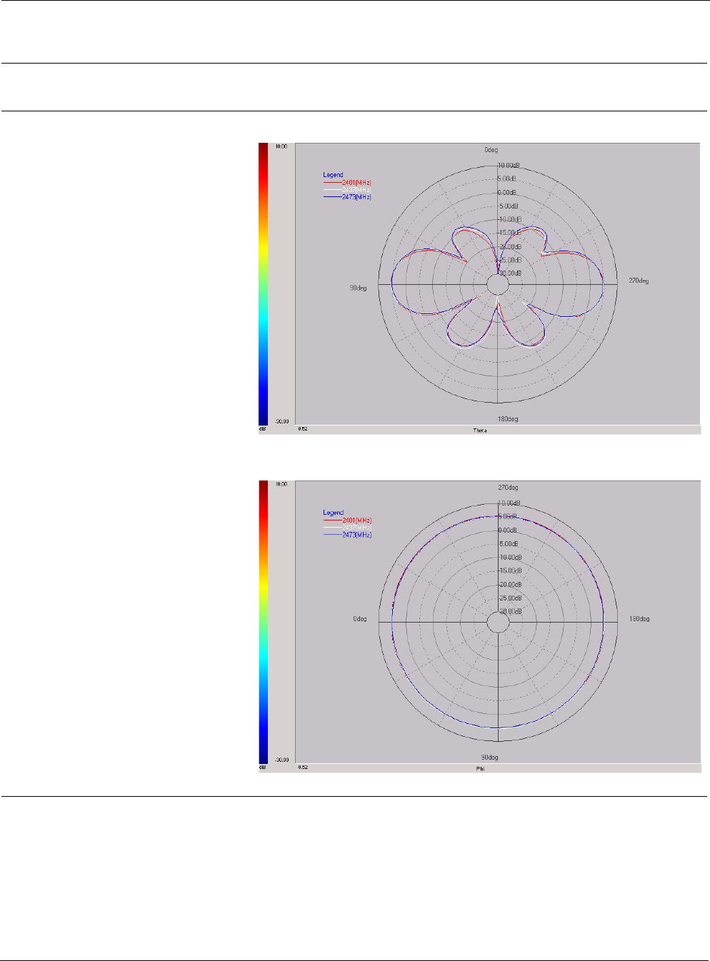
Table 13 Antenna Specifications and Patterns
Part
Number Specifications Pattern
AN060077 One outdoor 6.0dBi
omni unit-mounted antenna;
N connector
•Length: 11.9 in (30.3 cm)
•Weight: 4.4 oz (.125 kg)
•Color: White
•Measured peak gain:
5.3dBi
•Connector type: N male
Elevation
Azimuth
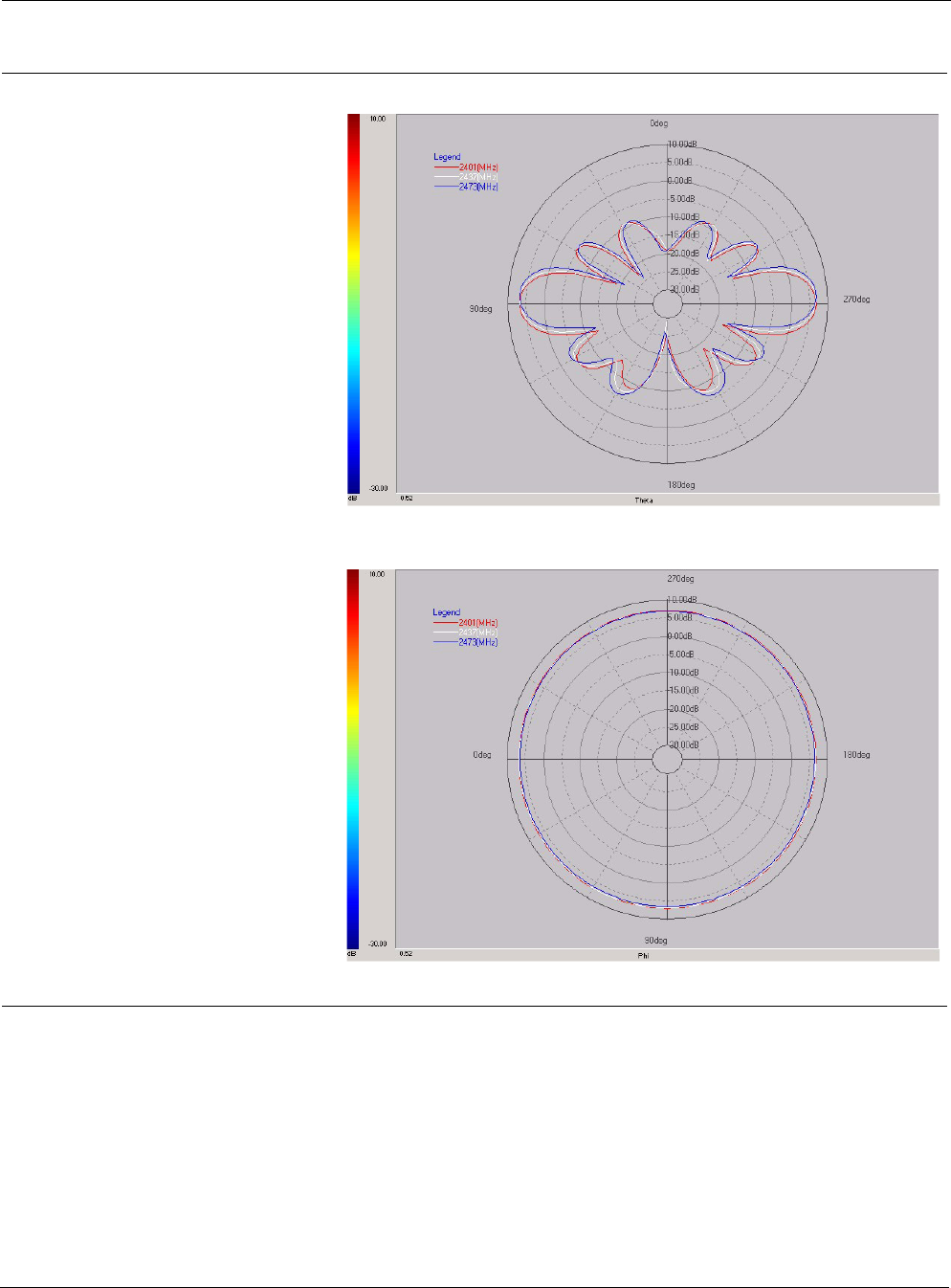
Tropos 5320 MetroMesh Router Installation Guide 55
AN074077
AN074088
One outdoor 7.4dBi omni
unit-mounted antenna;
N connector
•Length: 19 in (48.3 cm)
•Weight: 4.7 oz (.133 kg)
•Color: White
•Measured peak gain:
7.1dBi
•Connector type: N male
One outdoor 7.4dBi omni
mast-mounted antenna;
N connector; bracketry
•Length: 19 in (48.3 cm)
•Weight: 4.7 oz (.133 kg)
•Color: White
•Measured peak gain:
7.1dBi
•Connector type: N male
Elevation
Azimuth
Table 13 Antenna Specifications and Patterns (continued)
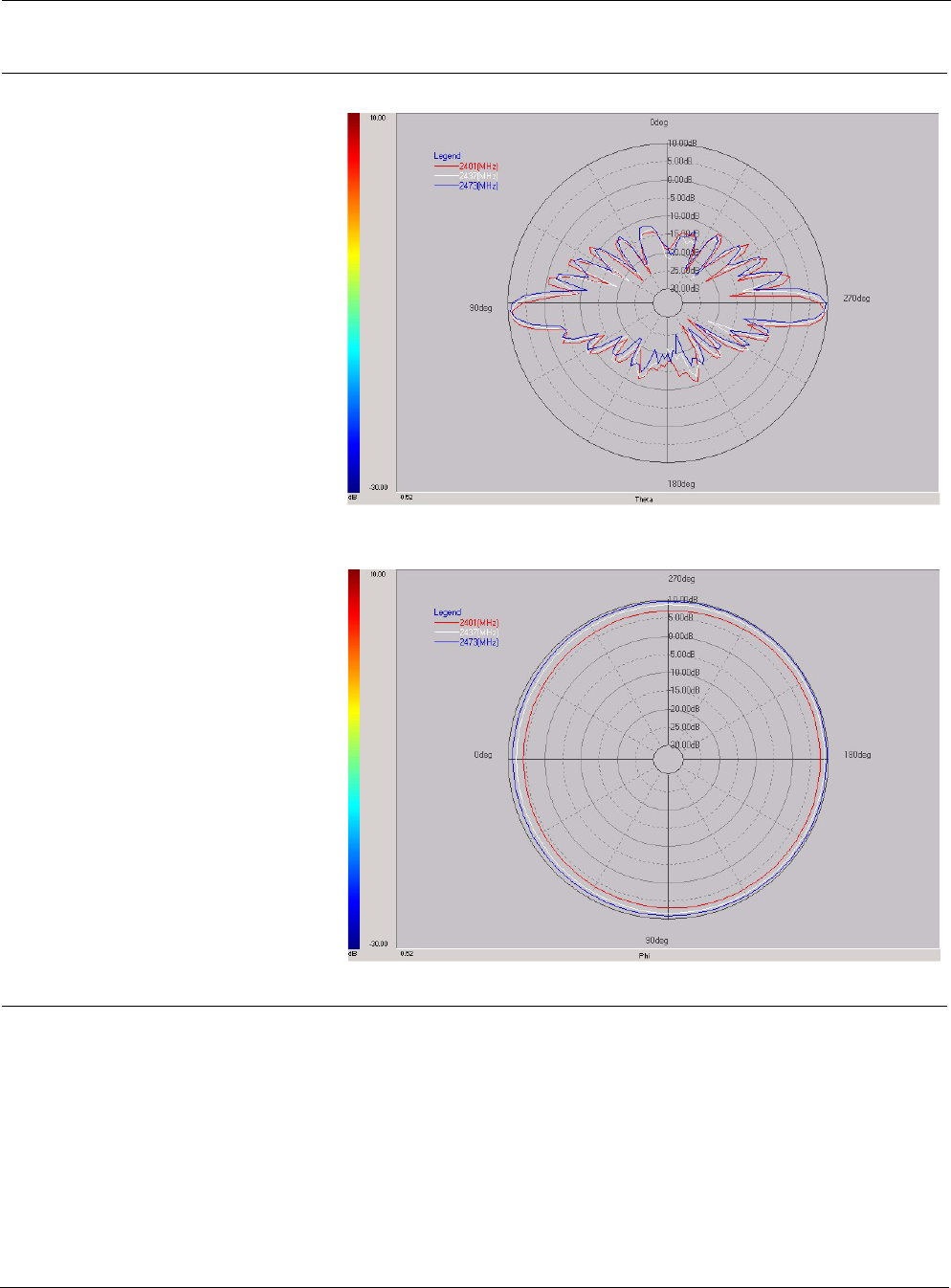
Tropos 5320 MetroMesh Router Installation Guide 56
AN100022 One outdoor 9.9dBi omni
mast-mounted antenna;
N connector; bracketry
•Length: 45 in (114.3 cm)
•Weight: 20 oz (.57 kg)
•Color: White
•Measure peak gain: 9.9dBi
•Connector type: N female
Elevation
Azimuth
Table 13 Antenna Specifications and Patterns (continued)
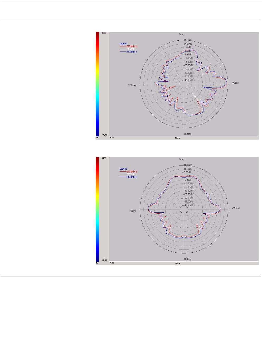
Tropos 5320 MetroMesh Router Installation Guide 57
AN120022 One outdoor 12.0dBi 90°
sector antenna;
N connector; bracketry
•Length: 34 in (86.4 cm)
•Width: 3 in (7.6 cm)
•Depth: 1.2 in (3.0cm)
•Weight: 25.6 oz (.73 kg)
•Color: Gray
•Measured peak gain:
12.0dBi
•Connector type: N female
Elevation (Phi=0°)
Elevation (Phi=90°)
Table 13 Antenna Specifications and Patterns (continued)
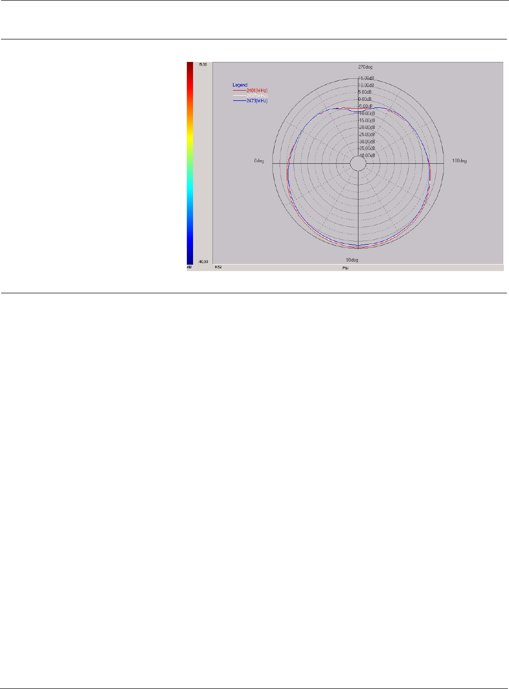
Tropos 5320 MetroMesh Router Installation Guide 58
AN120022
(continued)
Outdoor 12.0dBi 90° sector
antenna (continued)
Azimuth
Table 13 Antenna Specifications and Patterns (continued)
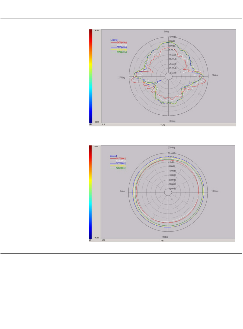
Tropos 5320 MetroMesh Router Installation Guide 59
AN091058 Outdoor 9.1dBi omni
antenna;
N connector
•Length: 17.5 in (43.2 cm)
•Weight: 4.7 oz (.133 kg)
•Color: White
•Measured peak gain: 6.7
dBi
•Connector Type: N Male
Elevation
Azimuth
Table 13 Antenna Specifications and Patterns (continued)
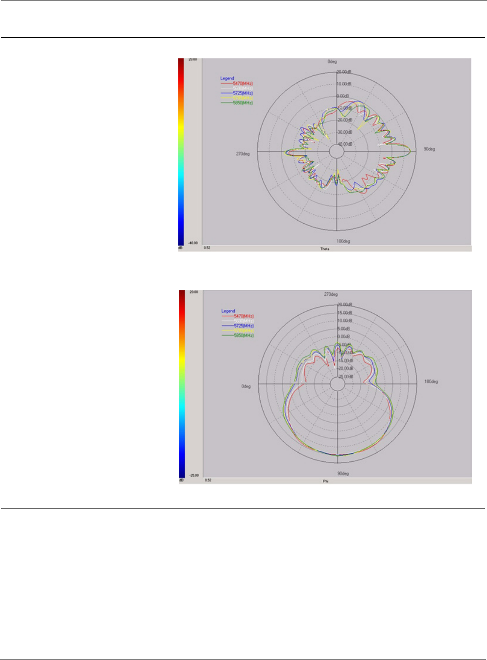
Tropos 5320 MetroMesh Router Installation Guide 60
AN170058 Outdoor 17.0dBi 90° sector
antenna;
N connector, bracketry
•Length: 14.5 in (370 cm)
•Width: 6.7 in (170 cm)
•Depth: 2.5 in (65 cm)
•Weight: 2.2 lbs (1 kg)
•Color: gray
•Measured peak gain: 15.3
dBi
•Connector Type: N Female
Elevation
Azimuth
Table 13 Antenna Specifications and Patterns (continued)
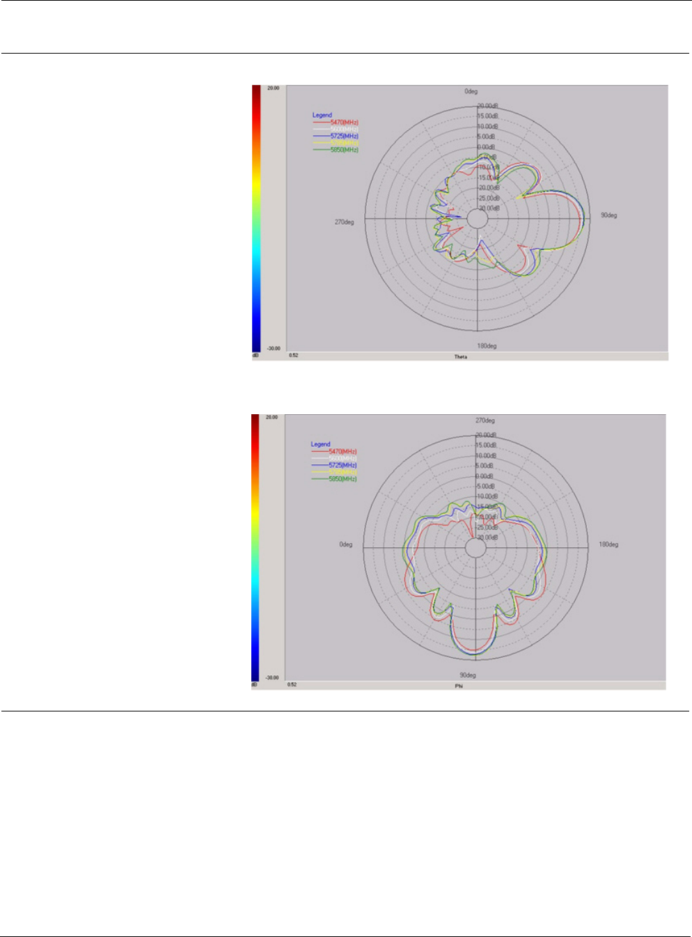
Tropos 5320 MetroMesh Router Installation Guide 61
AN190058 Outdoor 19.0dBi 16° patch
antenna;
N connector, bracketry
•Length: 7.45 in (189 cm)
•Width: 7.45 in (189 cm)
•Depth: 1.37 in (35 cm)
•Weight: 1.6 lbs (0.72 kg)
•Color: gray
•Measured peak gain: 17.3
dBi
•Connector Type: N Female
Elevation
Azimuth
Table 13 Antenna Specifications and Patterns (continued)

Tropos 5320 MetroMesh Router Installation Guide 62
AN170054 One outdoor 17.0dBi 90°
sector antenna;
N connector; bracketry
•Length: 14.5 in (370 cm)
•Width: 6.7 in (170 cm)
•Depth: 2.5 in (65 cm)
•Weight: 2.2 lbs (1 kg)
•Color: gray
•Measured peak gain:
•Connector Type: N Female
Patterns not available
AN190054 One outdoor 19.0dBi 16°
patch antenna;
N connector; bracketry
•Length: 7.45 in (189 cm)
•Width: 7.45 in (189 cm)
•Depth: 1.37 in (35 cm)
•Weight: 1.6 lbs (0.72 kg)
•Color: gray
•Measured peak gain:
•Connector Type: N Female
Patterns not available
Table 13 Antenna Specifications and Patterns (continued)

Tropos 5320 MetroMesh Router Installation Guide 63
6Installation Accessories
This chapter contains accessory ordering information:
“Installation Accessories” on page 63
“Tropos Antennas, Cables, and Related Ordering Numbers” on page 64
Table 14 Installation Accessories
Description Manufacturer Part Number Distributor Contact Information
Order
Number
Outdoor CAT5 4-Pair Data
Cable
Belden
Belden
7929A
7921A
(recommended)
Anixter
Anixter
www.anixter.com
www.anixter.com
Superior Essex BBDG Anixter www.anixter.com
Cable, CAT5, 8 Conductor,
Harsh Environment
Madison Cable 08KFK00013 Tyco www.xgsgroup.com
Self-Fusing EPR Tape 3M Scotch 23
Rubber Splicing
Tape
McMaster Carr
Alameda Electric
Distributors
www.mcmaster.com
www.alamedaelectric.com
7682A65
ThreadLocker LocTite 242 0.5
ml (0.017oz)
LocTite 242 McMaster Carr www.mcmaster.com 91458A24
3 pin AC Male Plug (cord end)
- 115 VAC 15A
Leviton 14W47-B Alameda Electric
Distributors
www.alamedaelectric.com
3 pin AC Female Receptacle
115 VAC 15A
Leviton 15W47 Alameda Electric
Distributors
www.alamedaelectric.com
3 pin AC Plug Female (cord
end) - Tropos 5320 router
Remke 50982 DSC Technical
Sales
www.dsctechnicalsales.com
Data Protection Device Polyphase IX-2H1DC48/W Electro-Comm www.electro-comm.com
Hyperlink HGLN-CAT5-1 www.hyperlinktech.com

Tropos 5320 MetroMesh Router Installation Guide 64
Yellow 3-Pin Mini-Link AC Plug
Female Pig Tail Unterminated
12 ft.
McMaster-Carr 321K16 www.mcmastercarr.com
Anti-seize lubricant Loctite 37230 McMaster Carr www.mcmaster.com
Universal remote control Universal
Remote
MX-500 www.universalremote.com
Table 14 Installation Accessories
Description Manufacturer Part Number Distributor Contact Information
Order
Number
Table 15 Tropos Antennas, Cables, and Related Ordering Numbers
Part Number Description
AN060077 One outdoor 6.0dBi omni unit-mounted antenna; N connector
AN074077 One outdoor 7.4dBi omni unit-mounted antenna; N connector
AN074088 One outdoor 7.4dBi omni mast-mounted antenna; N connector; bracketry
AN100022 One outdoor 9.9dBi omni mast-mounted antenna; N connector; Mounting Bracket;
Sealing Materials
AN120022 One outdoor 12.0dBi 90° sector antenna; N connector with pole-mount bracketry;
Sealing Materials (RF cable not included)
RC003400 3' N (male) to N (male) cable - LMR 400 DB
RC006400 6' N (male) to N (male) cable - LMR 400 DB
RC005000 50 ohm terminator - N (male); Sealing Materials
RC008000 Sealing Kit - Loctite242, EPR Rubber Splicing Tape
RC008100 N connector cover/cap, outdoor, water tight
RC009000 N adapter for 7.4dBi Mast-mounted antenna to N (male) cable
SA006801 Indoor Cat 5 data cable surge protector
SA006802 Indoor Cat5 data cable surge protector for shielded cable
PT021004 5320 input power cable - photo-electric cell adaptor; 2-wire; 4 ft.
PT021020 5320 input power cable - photo-electric cell adaptor; 2-wire; 20 ft.
PT031006 5320 input power cable - watertight plug; 3-wire; 6 ft.
PT031030 5320 input power cable - watertight plug; 3-wire; 30 ft.

Tropos 5320 MetroMesh Router Installation Guide 65
PT032030 5320 input power cable - pigtail, 3-wire, 30 ft., for EU markets
EC003500 5320 weathertight gateway connector kit
EC003600 5320 weathertight field-installable cable gland
EC003704 5320 weathertight RJ45 data cable, crossover, 4 ft (requires EC003500 gateway
connector kit)
EC003708 5320 weathertight RJ45 data cable, crossover, 8 ft (requires EC003500 gateway
connector kit)
MB0044300 5320 unit-attached mounting pole for Canopy SM; bracket and cable
MB005320 Pole mounting kit, 5320 HFC
Table 15 Tropos Antennas, Cables, and Related Ordering Numbers
Part Number Description

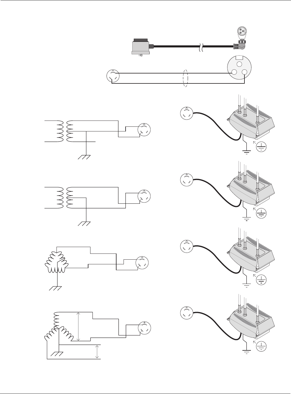
Tropos 5320 MetroMesh Router Installation Guide 67
Figure 27 AC Wiring — Photoelectric Power Tap
trp_161
White
Length: 4' or 20'
PT021004 (4') or PT021020 (20')
Photoelectric Power-Tap
Power Input Cable
2Wire - 90-480Vac
NEMA Plug - UL Standard 773
Plug-in locking type for
photocontrols in use with
area lighting
Carol P-7K-123033 MSHA or equal
1 - Green
2 - Black
3 - White
16/2 SOOW
North
Black
L2 / N
L1
Three phase; two wire service (Delta)
L1
Black
White
Protective Earth
L2
NEMA Photoelectric
Control / UL773
(female)
NEMA Photoelectric
Control / UL773
Power-Tap Adapter
(male)
North
L1
L2
North
Power-Tap single phase; two wire service
L1 Black
White
Protective Earth
L2 NEMA Photoelectric
Control / UL773
(female)
NEMA Photoelectric
Control / UL773
Power-Tap Adapter
(male)
North
White
N
White
L2
Black
L1
Black
L1
L1
N
North
Power-Tap single phase; two wire service
L1 Black
Red
Protective Earth
L2
NEMA Photoelectric
Control / UL773
(female)
NEMA Photoelectric
Control / UL773
Power-Tap Adapter
(male)
North
White
L2
Black
L1
L1
L2
North
208Vac three phase; two wire service (grounded-Wye)
L1
Black
Red
Protective Earth
L2 NEMA Photoelectric
Control / UL773
(female)
NEMA Photoelectric
Control / UL773
Power-Tap Adapter
(male)
North
L1
L2
277Vac
480Vac
North
White
L2
Black
L1
N
L3
1
23
Router
Router
Router
Router
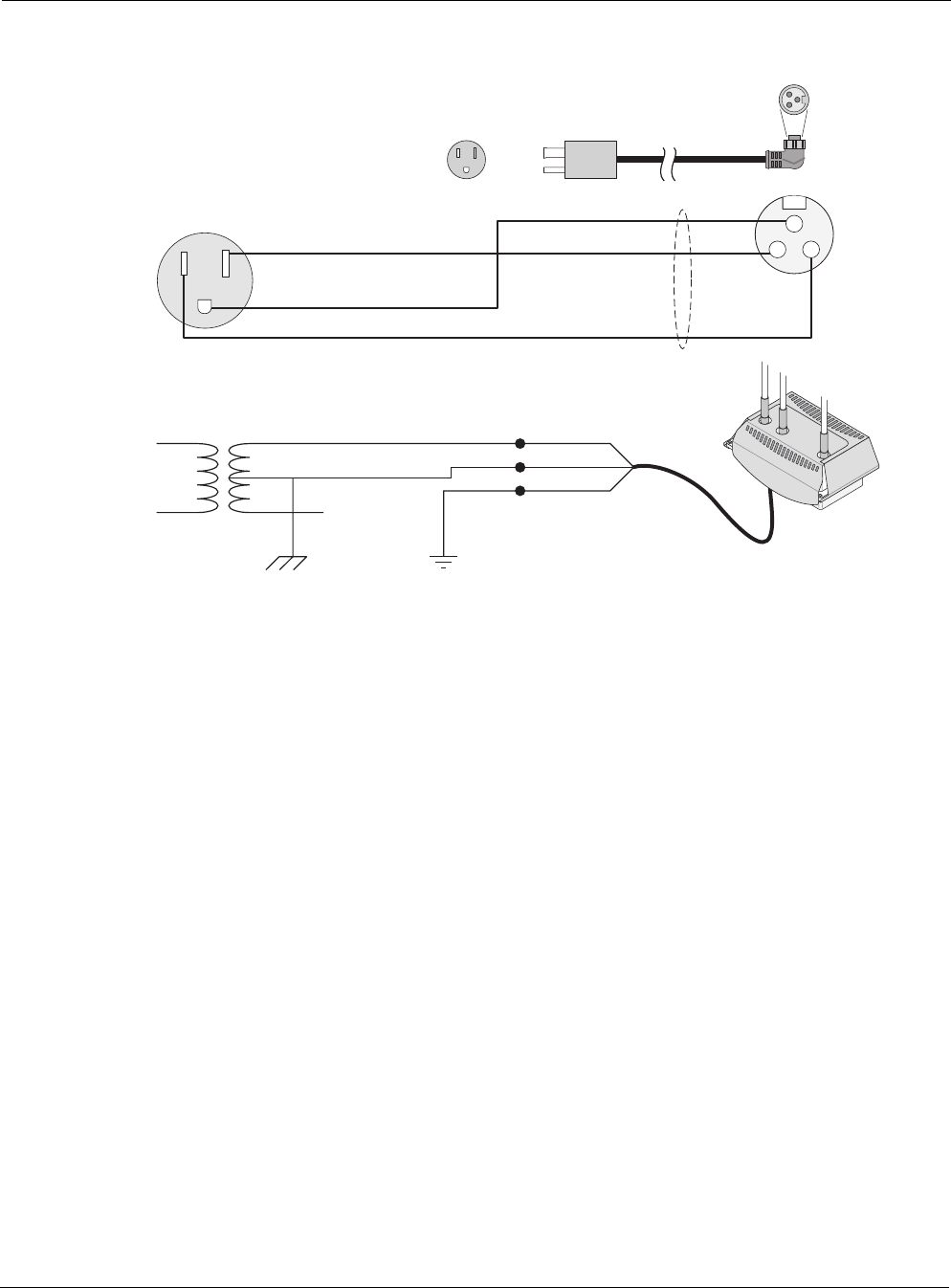
Tropos 5320 MetroMesh Router Installation Guide 68
Figure 28 AC Wiring Power Cable 120VAC, 15A Plug
trp_162
1 - Green
2 - Black
3 - White
Length: 3' to 30'
16/3 SOOW
L1 Black
White
Black
Black
White
White
Protective Earth
Green or Green/Yellow
Green or Green/Yellow
Green
120Vac single phase; three wire service
L1
Neutral
Black
White
Green
Black (L1)
White (N)
Green
Protective Earth
L2
Input Power
Cable
PT031006 (6’) or PT031030 (30’)
Overvoltage Category 2 or
IEEE/ANSI C62.41 Category B
Power Electrical Service Cable
3Wire - 120Vac
1
L2/N 3 2
Router

Tropos 5320 MetroMesh Router Installation Guide 69
8Wind Loading Considerations
The American Association of State Highway and Transportation Officials (AASHTO) standards
manual, “Standard Specifications for Structural Supports for Signs, Luminaires and Traffic
Signals,” governs most structural support issues related to traffic lighting and controls. Many
state and city public works departments site the AASHTO standard as the guide for their
requirements. Local municipalities in coastal states, which experience frequent hurricanes, etc.,
may have exceptions to the AASHTO standard that require higher design limits for wind
velocity or dead load.
Numerous pole and mast arm assemblies are used for traffic controls and traffic lighting. Each
assembly and installation is unique and worthy of an evaluation of the static and dynamic load
bearing capabilities; however, in most cases, the assembly will include a pole with a single 6', 9'
or 12' mast arm holding a single luminaire. Many of these mast arms are typically designed to
hold hundreds of pounds of static load and to carry several square meters of sail area in 80mph
winds. The typical mast arm is capable of supporting a single traffic control (typically weighing
around 160 lbs) and a single traffic sign (typically presenting a few square meters of sail area). A
single luminaire typically weighs about 60 lbs and presents about 3 square feet of sail area.
Note
Each assembly and installation is unique and worthy of an evaluation of the static and
dynamic load bearing capabilities. It is your responsibility to evaluate the load bearing
capabilities of the structure.
The Tropos 5320 MetroMesh Router weighs approximately 14 lbs, including all mounting
hardware. The Tropos 5320 MetroMesh Router may be mounted to either the pole portion of the
streetlight or to the mast arm portion.
When the Tropos 5320 MetroMesh Router is mounted to the pole or mast arm, most of the unit
is hidden by the pole or mast arm and therefore presents minimal additional sail area to the
structure. When the Tropos 5320 MetroMesh Router is mounted to the pole portion of the
structure, the sail area of the router is approximately 1 square foot. Pole manufacturers have
advised Tropos Networks that small communications devices such as the Tropos 5320
MetroMesh Router do not present any significant static or dynamic load to these structures.

Tropos 5320 MetroMesh Router Installation Guide 70
9Canopy Installation Instructions
The 5320 Canopy Subscriber Module and Bracket kit allows you to attach a third-party radio,
the Motorola Canopy Subscriber Module, to the Tropos 5320 MetroMesh Router.
The kit includes the following items:
Outdoor CAT5 weatherproof cable
Bracket (metal pole)
Screws #6-32 x 1.5"
Lockwashers
Cable ties
Follow these steps to install the canopy (refer to Figure 29):
1. Align the bracket and attach it using the three screws included in the kit.
2. Attach your radio subscriber module to the end of the bracket. Direct the Canopy Subscriber
Module toward the canopy base station.
3. Remove the cable access cover on the Canopy Subscriber Module so that you can attach the
RJ45 end of the data cable to the module. (The cover slides off.) Put the cable access cover
back in place.
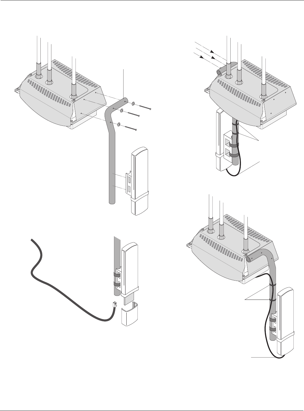
Tropos 5320 MetroMesh Router Installation Guide 71
Figure 29 Canopy Assembly
trp_163
Cable access
cover
Screws
#6-32 x 1.5"
Canopy radio
subscriber
module
4' weatherproof
cable
Screws
#6-32 x 1.5"
Lock
washers
Alternate
radio
installation
Cable ties
Finished
installation
Canopy bracket
Cable ties
Drip loop
Drip loop

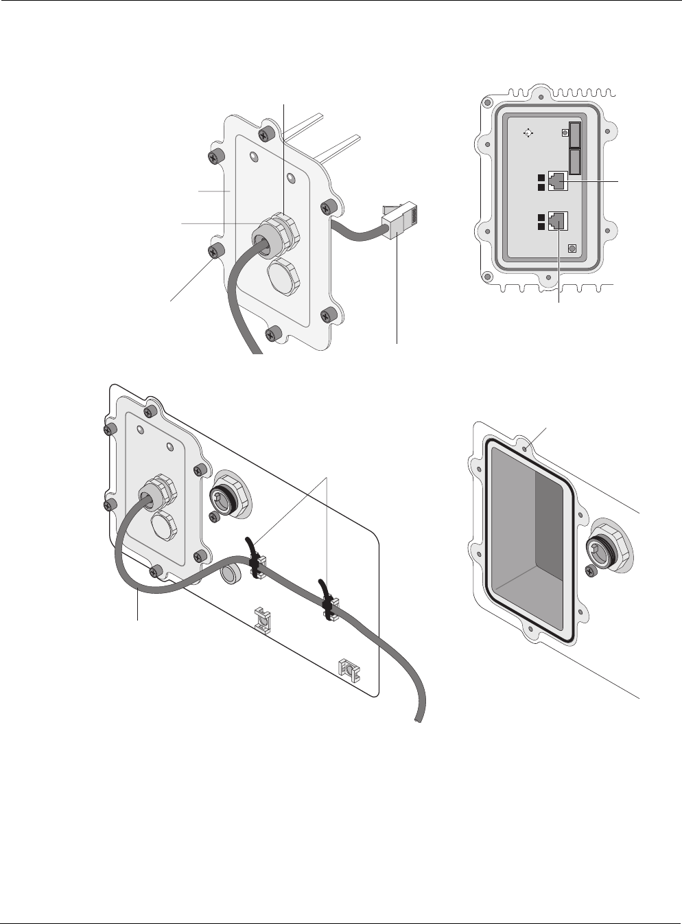
Tropos 5320 MetroMesh Router Installation Guide 73
Figure 30 Cable Connections
6. Attach the access cover by tightening the 6 screws. Check that the cable gland is securely
tightened.
7. Secure the weatherproof cable to the canopy bracket with two cable ties (Figure 29). Use
two additional cable ties to anchor the cable to the bottom of the 5320 unit (Figure 30). Refer
to Table 16 for canopy cable wiring information.
trp_122a
Connector
access cover
Tighten six screws to
fasten access cover
Watertight access cover
cable glands
Cable terminated
with RJ45 jack
for port connection
Shield
termination
Cable from radio
Management
port
LAN
port
Screw holes
for access cover
Cable ties
Drip loop

Tropos 5320 MetroMesh Router Installation Guide 74
Table 16 Canopy Cable Wiring
Canopy SM
(RJ45) Color
Tropos 5320
MetroMesh
Router Signal
3 Orange 1 TXD+
6 Orange-White 2 TXD-
1 Blue 3 RXD+
7 Green 4 24Vdc+
8 Green-White 5 24Vdc+
2 Blue-White 6 RXD-
4 Brown 7 24Vdc_RTN
5 Brown-White 8 24Vdc_RTN
Shield Drain wire Shield Shield
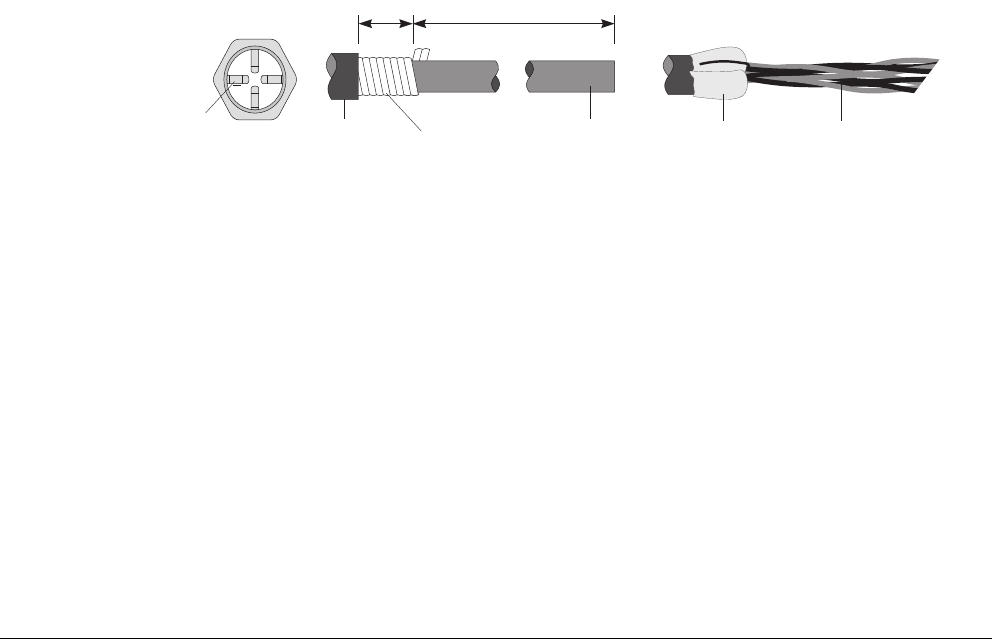
Tropos 5320 MetroMesh Router Installation Guide 75
10 Cable Termination Instructions
Follow these steps to prepare and terminate cables connected to the 5320 unit:
1. Strip off the outer sheath of cable to expose 6 inches of the inner cable or twisted pairs. The
shield may be armored, braided or foil type depending upon cable type (see Table 31).
2. For armored or braided cable, remove all but 1/2 inch of the armor or braid.
Remove waxy residues on the shields of “flooded” type cables.
For foil shielded cable, remove all but 1/2 inch of the foil, and fold the foil part back onto
the outer sheath. Most foil shields are conductive on the inner side, as the outer side
typically has a plastic coating.
The exposed conductive surfaces will ground to the conductive contacts inside the cable
gland.
Figure 31 Cable Components
Outer
jacket
Twisted
pairs
Armor or braided
conductive shield
1/2 inch 5-1/2 inches
Outer
jacket
Foil
conductive side out
Cable gland
Conductive
contacts
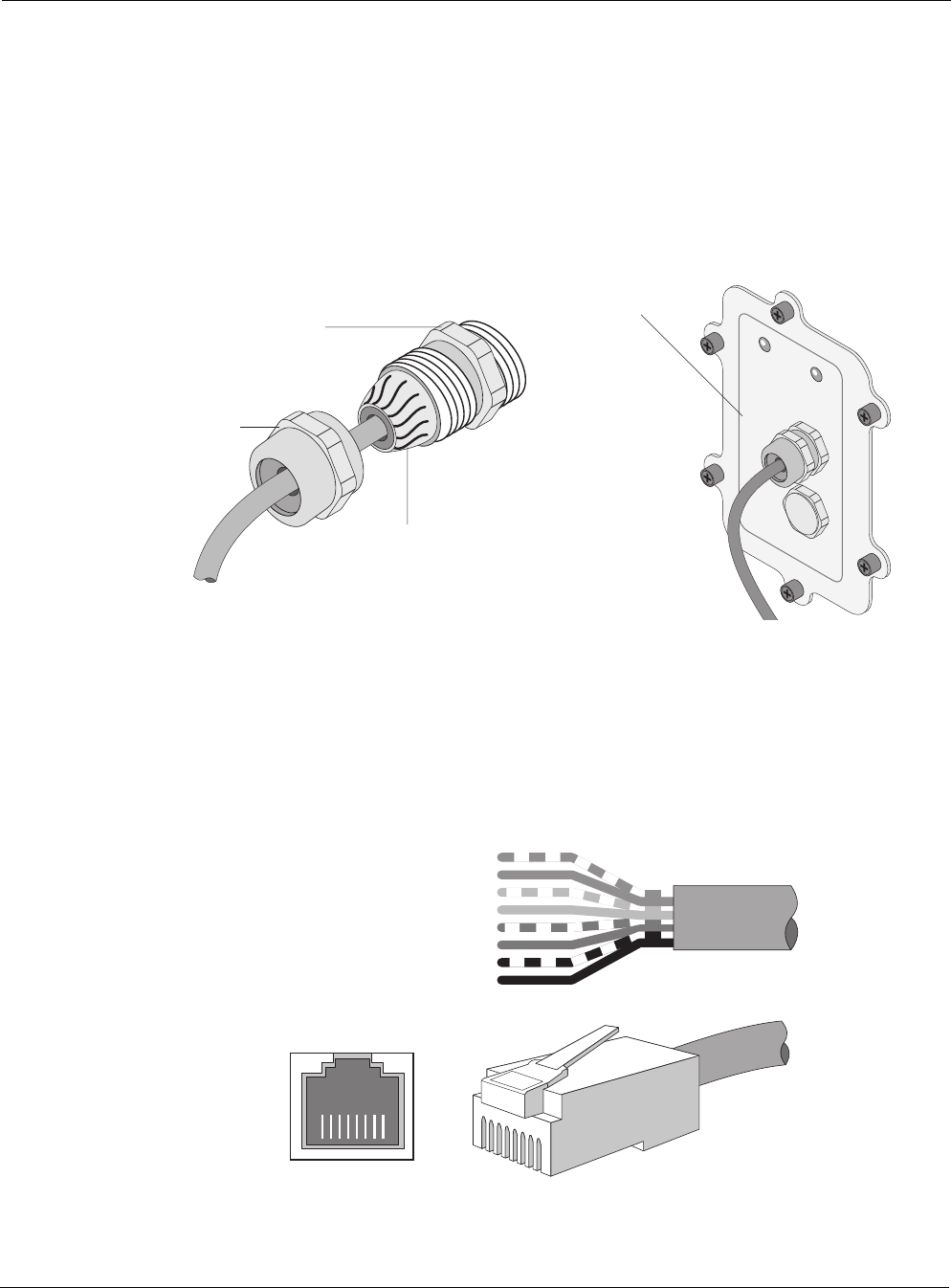
Tropos 5320 MetroMesh Router Installation Guide 76
3. Run the stripped part of the cable through the cable gland (Figure 32). Make sure that the
braided conductive shield of the cable makes contact with the conductive contacts of the
cable gland (Figure 32).
4. Attach the cable gland by first tightening the gland base into the access cover. Then tighten
the gland cover to constrict the weather-tight grommet around the outer jacket of the cable,
thereby creating a weather-tight fitting.
Figure 32 Cable Gland Assembly
5. Apply a RJ45 modular jack and connect to the LAN or Management port. Figure 32 shows
the termination options, and Table 17 provides pin descriptions.
Figure 33 Cable Preparation and Termination
trp_123a
Accessory connector
access cover
Finished installation
Gland cover
then tightened
over cable
Cable gland
base tightened first
to cover
Weather-tight
grommet
trp_109
Category 5 cable
RJ45 port
RJ45 jack
8
1
2
3
4
5
6
7
Brown
Orange/white
Orange
Green/white
Blue
Blue/white
Green
Brown/white
18765432 7
68
5
4
3
2
1

Tropos 5320 MetroMesh Router Installation Guide 77
Table 17 TIA/EIA 5688 Wiring - RJ-45 Pin Descriptions for Data Connection
Pin T/R Signal Color Description
1 T TXD+ Orange-White TX Data 10/100BaseT
2 R TXD- Orange TX Data 10/100BaseT
3 T RXD+ Green-White RX Data 10/100BaseT
4 R PoE+ Blue Power output, 0, 12, 24, 48 Vdc (+)
5 T PoE+ Blue-White Power output, 0, 12, 24, 48 Vdc (+)
6 R RXD- Green RX Data 10/100BaseT
7 T PoE- Brown-White Power output, 0, 12, 24, 48 Vdc (-)
8 R PoE- Brown Power output, 0, 12, 24, 48 Vdc (-)

Tropos 5320 MetroMesh Router Installation Guide 78
Abbreviations
The following acronyms are used in this document.
Table 18 Acronyms
2P Two-Phase or Split Phase
2W Two-Wire
3W Three-Wire
AASHTO American Association of State Highway and Transportation Officials
AC Alternating Current
ANSI American National Standards Institute
AWG American Wire Gauge
C Celsius
CAT Category
CCK Complementary Code Keying
CE Conformite Europeene
CFR Code of Federal Regulations
CISPR International Special Committee on Radio Interference
CSA Canadian Standard Association
dB Decibels
dBi Decibels Relative to an Isotropic Radiator
dBm Decibels Referred to 1 Milliwatt
DBPSK Differential-Binary Phase-Shift Keying
DC Direct Current

Tropos 5320 MetroMesh Router Installation Guide 79
DGT Directorate General of Telecommunications (Taiwan)
DQPSK Differential-Quadrature Phase-Shift Keying
DSSS Direct-Sequence Spread Spectrum
EFT Electrically Fast Transients
EIRP Effective Isotropic Radiated Power
EMC Electromagnetic Compatibility
EN IEC standard
ESD Electrostatic Discharge
ETSI European Telecommunications Standards Institute
FCC Federal Communications Commission
FHSS Frequency Hopping Spread Spectrum
HFC Hybrid Fiber Coax
Hz Hertz
IEC International Electrotechnical Commission
IEEE Institute of Electrical and Electronics Engineers
IP67 Ingress Protection Standard
ISM Instrumentation, Scientific, and Medical band
ISTA International Safe Transit Association
LAN Local Area Network
Mbps Megabits Per Second
MHz Megahertz
MIL-STD Military Standard
MPHPT Ministry of Public Management, Home Affairs, Posts and Telecommunications (Japan)
MSO Multiple Service Operator
MTBF Mean Time Between Failure
N Neutral
NEC National Electrical Codes
Table 18 Acronyms (continued)

Tropos 5320 MetroMesh Router Installation Guide 80
NEMA National Electrical Manufacturers Association
OFDM Orthogonal Frequency Division Multiplexing
P Phase
PE Protective Earth
PoE Power over Ethernet
RJ45 Registered Jack 45
RSS Received Signal Strength
Rx Receive
RXD Receive Data
TUV Technical Inspection Association
Tx Transmit
TXD Transmit Data
UL Underwriters Laboratories
UPS Uninterruptible Power Supply
VAC Voltage (Alternating Current)
VCCI Voluntary Control Council for Interference (Japan)
VDC Voltage (Direct Current)
VSWR Voltage Standing Wave Ratio
WWatts
Table 18 Acronyms (continued)

Tropos 5320 MetroMesh Router Installation Guide
Index
A
AC
power source 6
wiring diagrams 66
American Association of State High-
way and Transportation Officials
(AASHTO) 69
antenna type and placement 5
antennas
approved configurations 48
connecting 18
distances from people 5
external 19
omni-directional 5
options 5
waterproofing 20
attenuation 50
B
battery
backup 37
turning router off 34
battery backup vs. throughput chart
37, 38
building materials 5
C
cable
gland 76
termination 75
canopy installation 70
canopy subscriber module and bracket
kit 70
categories of power 24
category A power 25
category B power 25
category C power 25
cautions vi
circuit board connection locations 34
clearance for mounting 7
concrete pole mounting 9
connecting
antennas 18
category III AC power 27
power 24
connecting a data port 29
connecting data ports 32
connecting peripherals 35
D
data cables 31
attaching before mounting 7
data port
connecting 29
connection options 31
data protection device 23
data rate considerations 5
distance limits 4
diversity 5
E
external antennas 19
F
FCC antenna rules 2
G
grounding
connecting 23
data protection device 23
router 21
H
hardware reset 34
hose clamps 8
I
installation considerations
antenna options 5
site surveys 5
installation hardware and tools 4
installing Tropos router 1
L
LAN port 29
LED 34
location guidelines 5
M
management port 29
metal pole mounting 10
mounting
clearance 7
instructions 9
metal pole 10
orientation 7
poles greater than 8 inches diameter
8
strategies 7
streetlight 17
streetlight options 7
to wood, concrete, painted poles 9
tower 16
wood brace 14
wood pole 13
O
obstructions 5
omni-directional antenna 5
P
peripherals
connecting 35
physical environment 5
pole mounting 10
ports 29
power
categories 24
connecting 24
connecting category III AC power 27
connecting streetlight 28
consumption 40
output 35
power over Ethernet (PoE) 35
power sources
overview 6
preparing for installation 2
product specifications 42
R
regulatory notices ii
resetting the router 34
RJ45 Ethernet ports 29
RJ45 pin descriptions 77
RJ45 pin locations and descriptions 36
router
diagram 3
exploded view 3
resetting 34
S
safety
general considerations 6
information 38
site planning 4

Tropos 5320 MetroMesh Router Installation Guide
site surveys 5
specifications 42
streetlight
mounting instructions 17
mounting options 7
power 28
sun shield 12
T
terminating cables 75
tools for installation 4
tower mounting 16
V
voltage 6
W
warnings, general vi
waterproofing antenna connections 20
wind loading 69
wiring diagrams 66
wood brace mounting 14
wood pole mounting 13